Embed Size (px)
Citation preview
Quick Start Guide00825-0300-4728, Rev CA
September 2016
Rosemount™ 644H Temperature Transmitters with PROFIBUS® PA
00825-0300-4728_RevCA.fm Page 1 Tuesday, September 13, 2016 4:22 PM
September 2016Quick Start Guide
00825-0300-4728_RevCA.fm Page 2 Tuesday, September 13, 2016 4:22 PM
NOTICEThis guide provides basic guidelines for the Rosemount 644. It does not provide instructions for detailed configuration, diagnostics, maintenance, service, troubleshooting, or installation. Refer to the Rosemount 644 Reference Manual for more instruction. The manual and this guide are also available electronically on EmersonProcess/Rosemount.
Explosions could result in death or serious injury.
Installation of this transmitter in an explosive environment must be in accordance with the appropriate local, national, and international standards, codes, and practices. Review the approvals section of the Rosemount 644 Reference Manual for any restrictions associated with a safe installation.
In an Explosion-proof/Flameproof installation, do not remove the transmitter covers when power is applied to the unit.
Process leaks may cause harm or result in death. Install and tighten thermowells or sensors before applying pressure.Do not remove the thermowell while in operation.
Electrical shock can result in death or serious injury.Avoid contact with the leads and terminals. High voltage that may be present on leads can cause electrical
shock.
ContentsMount the transmitter . . . . . . . . . . . . . . . . . . . . 3Wire and apply power . . . . . . . . . . . . . . . . . . . . . 4Verify tagging . . . . . . . . . . . . . . . . . . . . . . . . . . . . 8
Transmitter configuration . . . . . . . . . . . . . . . . . 8Product Certifications . . . . . . . . . . . . . . . . . . . 11
2
Quick Start GuideSeptember 2016
00825-0300-4728_RevCA.fm Page 3 Tuesday, September 13, 2016 4:22 PM
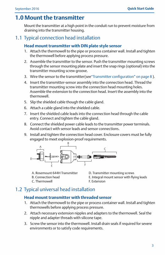
1.0 Mount the transmitterMount the transmitter at a high point in the conduit run to prevent moisture from draining into the transmitter housing.
1.1 Typical connection head installation
Head mount transmitter with DIN plate style sensor1. Attach the thermowell to the pipe or process container wall. Install and tighten
the thermowell before applying process pressure.
2. Assemble the transmitter to the sensor. Push the transmitter mounting screws through the sensor mounting plate and insert the snap rings (optional) into the transmitter mounting screw groove.
3. Wire the sensor to the transmitter (see“Transmitter configuration” on page 8 ).
4. Insert the transmitter-sensor assembly into the connection head. Thread the transmitter mounting screw into the connection head mounting holes. Assemble the extension to the connection head. Insert the assembly into the thermowell.
5. Slip the shielded cable though the cable gland.
6. Attach a cable gland into the shielded cable.
7. Insert the shielded cable leads into the connection head through the cable entry. Connect and tighten the cable gland.
8. Connect the shielded power cable leads to the transmitter power terminals. Avoid contact with sensor leads and sensor connections.
9. Install and tighten the connection head cover. Enclosure covers must be fully engaged to meet explosion-proof requirements.
1.2 Typical universal head installation
Head mount transmitter with threaded sensor1. Attach the thermowell to the pipe or process container wall. Install and tighten
thermowells before applying process pressure.
2. Attach necessary extension nipples and adapters to the thermowell. Seal the nipple and adapter threads with silicone tape.
3. Screw the sensor into the thermowell. Install drain seals if required for severe environments or to satisfy code requirements.
A. Rosemount 644H TransmitterB. Connection headC. Thermowell
D. Transmitter mounting screwsE. Integral mount sensor with flying leadsF. Extension
D
A
E
B
F
C
3
September 2016Quick Start Guide
00825-0300-4728_RevCA.fm Page 4 Tuesday, September 13, 2016 4:22 PM
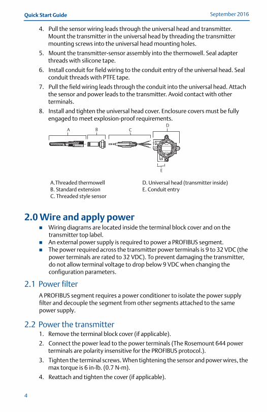
4. Pull the sensor wiring leads through the universal head and transmitter. Mount the transmitter in the universal head by threading the transmitter mounting screws into the universal head mounting holes.
5. Mount the transmitter-sensor assembly into the thermowell. Seal adapter threads with silicone tape.
6. Install conduit for field wiring to the conduit entry of the universal head. Seal conduit threads with PTFE tape.
7. Pull the field wiring leads through the conduit into the universal head. Attach the sensor and power leads to the transmitter. Avoid contact with other terminals.
8. Install and tighten the universal head cover. Enclosure covers must be fully engaged to meet explosion-proof requirements.
2.0 Wire and apply power Wiring diagrams are located inside the terminal block cover and on the
transmitter top label. An external power supply is required to power a PROFIBUS segment. The power required across the transmitter power terminals is 9 to 32 VDC (the
power terminals are rated to 32 VDC). To prevent damaging the transmitter, do not allow terminal voltage to drop below 9 VDC when changing the configuration parameters.
2.1 Power filterA PROFIBUS segment requires a power conditioner to isolate the power supply filter and decouple the segment from other segments attached to the same power supply.
2.2 Power the transmitter1. Remove the terminal block cover (if applicable).
2. Connect the power lead to the power terminals (The Rosemount 644 power terminals are polarity insensitive for the PROFIBUS protocol.).
3. Tighten the terminal screws. When tightening the sensor and power wires, the max torque is 6 in-lb. (0.7 N-m).
4. Reattach and tighten the cover (if applicable).
A.Threaded thermowellB. Standard extensionC. Threaded style sensor
D. Universal head (transmitter inside)E. Conduit entry
A B CD
E
4
Quick Start GuideSeptember 2016
00825-0300-4728_RevCA.fm Page 5 Tuesday, September 13, 2016 4:22 PM
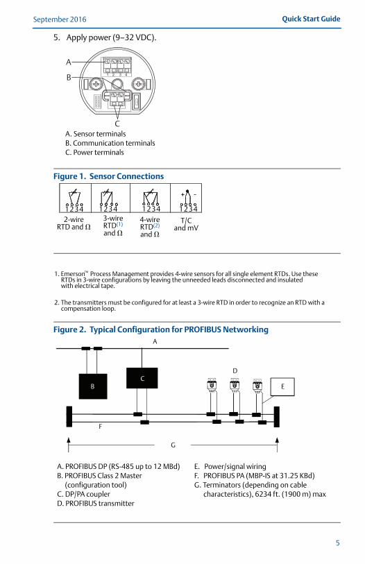
5. Apply power (9–32 VDC).
A. Sensor terminalsB. Communication terminalsC. Power terminals
Figure 1. Sensor Connections
1. Emerson ™ Process Management provides 4-wire sensors for all single element RTDs. Use these RTDs in 3-wire configurations by leaving the unneeded leads disconnected and insulated with electrical tape.
2. The transmitters must be configured for at least a 3-wire RTD in order to recognize an RTD with a compensation loop.
Figure 2. Typical Configuration for PROFIBUS Networking
A. PROFIBUS DP (RS-485 up to 12 MBd)B. PROFIBUS Class 2 Master
(configuration tool)C. DP/PA couplerD. PROFIBUS transmitter
E. Power/signal wiringF. PROFIBUS PA (MBP-IS at 31.25 KBd)G. Terminators (depending on cable
characteristics), 6234 ft. (1900 m) max
1 2 3 4
A
B
C
2-wire RTD and �
3-wireRTD(1) and �
4-wire RTD(2)
and �
T/C and mV
1234 1234 1234 1234
A
D
E
G
F
CB
5
September 2016Quick Start Guide
00825-0300-4728_RevCA.fm Page 6 Tuesday, September 13, 2016 4:22 PM
Note Each segment in a PROFIBUS trunk must be terminated at both ends. Some DP/PA couplers contain the power supply, one terminator, and the
power conditioner within the coupling device. The configuration tool is typically located in the control room.
2.3 Ground the transmitter
Ungrounded thermocouple, mV, and RTD/ohm inputs
Each process installation has different requirements for grounding. Use the grounding options recommended by the facility for the specific sensor type, or begin with grounding Option 1 (the most common).
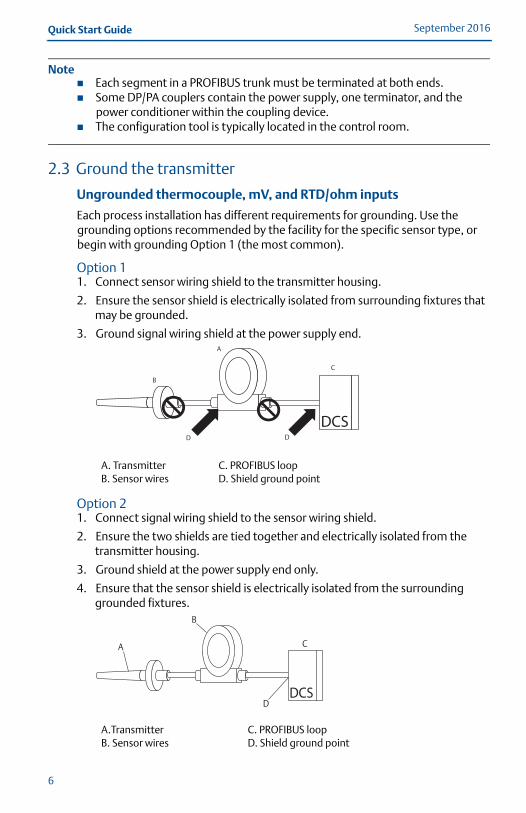
Option 11. Connect sensor wiring shield to the transmitter housing.
2. Ensure the sensor shield is electrically isolated from surrounding fixtures that may be grounded.
3. Ground signal wiring shield at the power supply end.
Option 21. Connect signal wiring shield to the sensor wiring shield.
2. Ensure the two shields are tied together and electrically isolated from the transmitter housing.
3. Ground shield at the power supply end only.
4. Ensure that the sensor shield is electrically isolated from the surrounding grounded fixtures.
A. TransmitterB. Sensor wires
C. PROFIBUS loopD. Shield ground point
A.TransmitterB. Sensor wires
C. PROFIBUS loopD. Shield ground point
A
B
C
D D
D
B
A C
6
Quick Start GuideSeptember 2016
00825-0300-4728_RevCA.fm Page 7 Tuesday, September 13, 2016 4:22 PM
NoteConnect shields together, electrically isolated from the transmitter
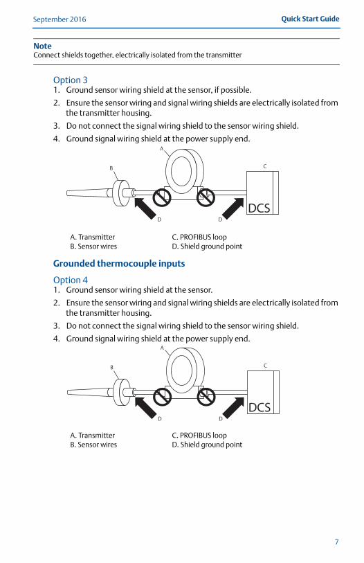
Option 3 1. Ground sensor wiring shield at the sensor, if possible.
2. Ensure the sensor wiring and signal wiring shields are electrically isolated from the transmitter housing.
3. Do not connect the signal wiring shield to the sensor wiring shield.
4. Ground signal wiring shield at the power supply end.
Grounded thermocouple inputs
Option 41. Ground sensor wiring shield at the sensor.
2. Ensure the sensor wiring and signal wiring shields are electrically isolated from the transmitter housing.
3. Do not connect the signal wiring shield to the sensor wiring shield.
4. Ground signal wiring shield at the power supply end.
A. TransmitterB. Sensor wires
C. PROFIBUS loopD. Shield ground point
A. TransmitterB. Sensor wires
C. PROFIBUS loopD. Shield ground point
A
B
D D
C
A
B
D D
C
7
September 2016Quick Start Guide
00825-0300-4728_RevCA.fm Page 8 Tuesday, September 13, 2016 4:22 PM
3.0 Verify tagging
4.0 Transmitter configurationEach PROFIBUS capable host or configuration tool has a different way of displaying and performing configurations. Some use Device Descriptions (DD) or DD methods for configuration and to display data consistently across platforms. There is no requirement that a host or configuration tool support these features. The following is the minimum configuration requirement for a temperature measurement. This guide is designed for systems not using DD methods. For a complete list of parameters and configuration information refer to the Rosemount 644 Head and Rail Mount Temperature Transmitter Reference Manual.
The Rosemount 644 must be configured via a Class 2 master (DD or DTM based). The basic configuration tasks for the PROFIBUS PA Temperature Transmitter include: Assign address Set sensor type and connection. Configure engineering units.
4.1 Assign addressThe Rosemount 644 is shipped with a temporary address of 126. This must be changed to a unique value between 0 and 125 in order to establish communication with the host. Usually, addresses 0-2 are reserved for masters or couplers, therefore transmitter addresses between 3 and 125 are recommended.
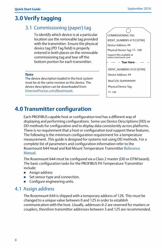
3.1 Commissioning (paper) tag To identify which device is at a particular location use the removable tag provided with the transmitter. Ensure the physical device tag (PD Tag field) is properly entered in both places on the removable commissioning tag and tear off the bottom portion for each transmitter.
NoteThe device description loaded in the host system must be at the same revision as this device. The device description can be downloaded from EmersonProcess.com/Rosemount.
COMMISSIONING TAG
IDENT_NUMBERS 4153 [9700]
Device Address: ##
Physical Device Tag: TT- 100
Support files available at www.rosemount.com
IDENT_NUMBERS 4153 [9700]
Device Address: ##
Mod S/N: 0x########
Physical Device Tag:
TT- 100
Tear Here
8
Quick Start GuideSeptember 2016
00825-0300-4728_RevCA.fm Page 9 Tuesday, September 13, 2016 4:22 PM
NoteWhen shipped from the factory Rosemount 644 PROFIBUS Profile 3.02 devices are defaulted in Identification Number ADAPTATION MODE. This mode allows the transmitter to communicate with any Profibus control host with either the generic Profile GSD file (9700) or the Rosemount 644 specific GSD (4153) loaded in the host; therefore, if is not required to change the transmitter identification number at startup.
Transducer function block
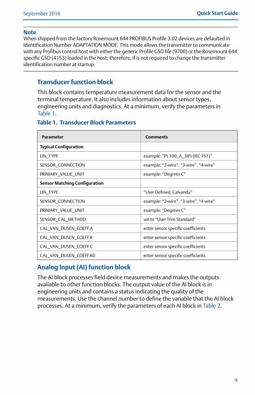
This block contains temperature measurement data for the sensor and the terminal temperature. It also includes information about sensor types, engineering units and diagnostics. At a minimum, verify the parameters in Table 1.
Analog Input (AI) function block
The AI block processes field device measurements and makes the outputs available to other function blocks. The output value of the AI block is in engineering units and contains a status indicating the quality of the measurements. Use the channel number to define the variable that the AI block processes. At a minimum, verify the parameters of each AI block in Table 2.
Table 1. Transducer Block Parameters
Parameter Comments
Typical Configuration
LIN_TYPE example: “Pt 100_A_385 (IEC 751)”
SENSOR_CONNECTION example: “2-wire”, “3-wire”, “4-wire”
PRIMARY_VALUE_UNIT example: “Degrees C”
Sensor Matching Configuration
LIN_TYPE “User Defined, Calvandu”
SENSOR_CONNECTION example: “2-wire”, “3-wire”, “4-wire”
PRIMARY_VALUE_UNIT example: “Degrees C”
SENSOR_CAL_METHOD set to “User Trim Standard”
CAL_VAN_DUSEN_COEFF.A enter sensor specific coefficients
CAL_VAN_DUSEN_COEFF.B enter sensor specific coefficients
CAL_VAN_DUSEN_COEFF.C enter sensor specific coefficients
CAL_VAN_DUSEN_COEFF.R0 enter sensor specific coefficients
9
September 2016Quick Start Guide
00825-0300-4728_RevCA.fm Page 10 Tuesday, September 13, 2016 4:22 PM
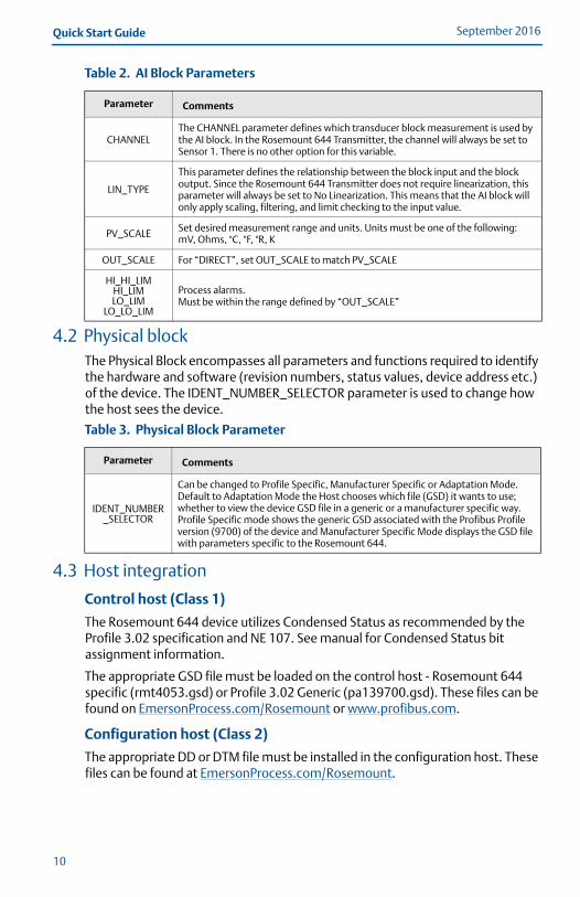
4.2 Physical blockThe Physical Block encompasses all parameters and functions required to identify the hardware and software (revision numbers, status values, device address etc.) of the device. The IDENT_NUMBER_SELECTOR parameter is used to change how the host sees the device.
4.3 Host integration
Control host (Class 1)
The Rosemount 644 device utilizes Condensed Status as recommended by the Profile 3.02 specification and NE 107. See manual for Condensed Status bit assignment information.
The appropriate GSD file must be loaded on the control host - Rosemount 644 specific (rmt4053.gsd) or Profile 3.02 Generic (pa139700.gsd). These files can be found on EmersonProcess.com/Rosemount or www.profibus.com.
Configuration host (Class 2)
The appropriate DD or DTM file must be installed in the configuration host. These files can be found at EmersonProcess.com/Rosemount.
Table 2. AI Block Parameters
Parameter Comments
CHANNELThe CHANNEL parameter defines which transducer block measurement is used by the AI block. In the Rosemount 644 Transmitter, the channel will always be set to Sensor 1. There is no other option for this variable.
LIN_TYPE
This parameter defines the relationship between the block input and the block output. Since the Rosemount 644 Transmitter does not require linearization, this parameter will always be set to No Linearization. This means that the AI block will only apply scaling, filtering, and limit checking to the input value.
PV_SCALE Set desired measurement range and units. Units must be one of the following:mV, Ohms, °C, °F, °R, K
OUT_SCALE For “DIRECT”, set OUT_SCALE to match PV_SCALE
HI_HI_LIMHI_LIMLO_LIM
LO_LO_LIM
Process alarms. Must be within the range defined by “OUT_SCALE”
Table 3. Physical Block Parameter
Parameter Comments
IDENT_NUMBER_SELECTOR
Can be changed to Profile Specific, Manufacturer Specific or Adaptation Mode.Default to Adaptation Mode the Host chooses which file (GSD) it wants to use; whether to view the device GSD file in a generic or a manufacturer specific way.Profile Specific mode shows the generic GSD associated with the Profibus Profile version (9700) of the device and Manufacturer Specific Mode displays the GSD file with parameters specific to the Rosemount 644.
10
Quick Start GuideSeptember 2016
00825-0300-4728_RevCA.fm Page 11 Tuesday, September 13, 2016 4:22 PM
5.0 Product CertificationsRev 1.14
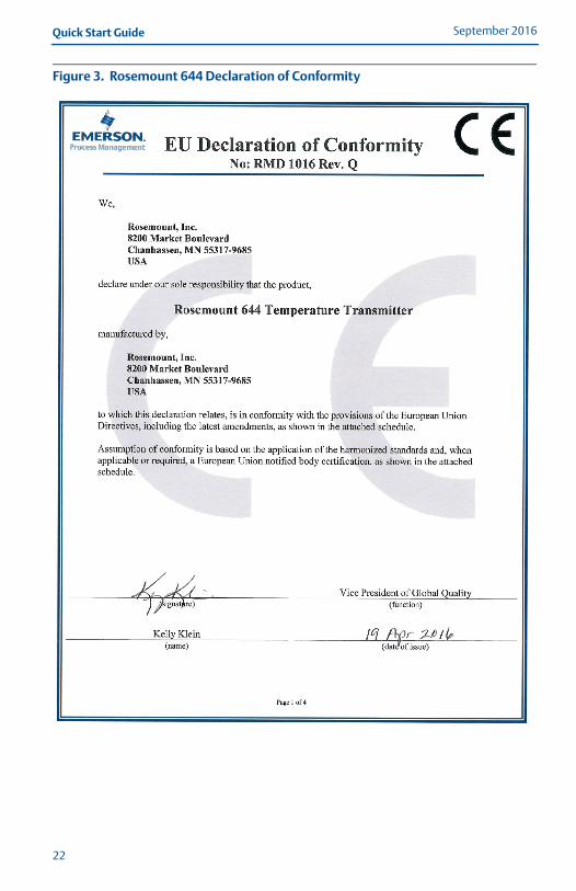
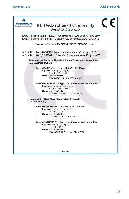
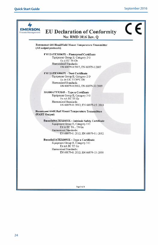
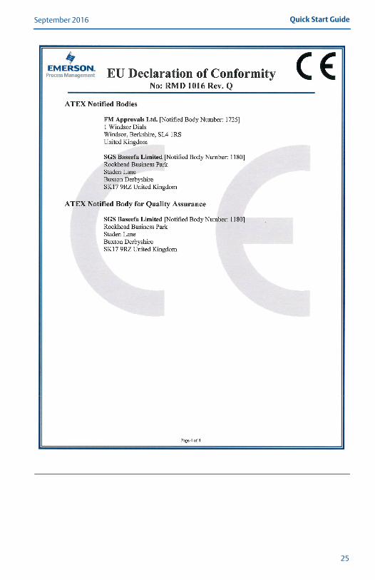
5.1 European Directive InformationA copy of the EU Declaration of Conformity can be found at the end of the Quick Start Guide. The most recent revision of the EU Declaration of Conformity can be found at EmersonProcess.com/Rosemount.
5.2 Ordinary Location Certification As standard, the transmitter has been examined and tested to determine that the design meets the basic electrical, mechanical, and fire protection requirements by a nationally recognized test laboratory (NRTL) as accredited by the Federal Occupational Safety and Health Administration (OSHA).
5.3 Installing Equipment in North AmericaThe US National Electrical Code® (NEC) and the Canadian Electrical Code (CEC) permit the use of Division marked equipment in Zones and Zone marked equipment in Divisions.The markings must be suitable for the area classification, gas, and temperature class.This information is clearly defined in the respective codes.
USAE5 USA Explosionproof, Non-Incendive, Dust-Ignitionproof
Certificate: [XP & DIP]: 3006278; [NI]: 3008880 & 3044581Standards: FM Class 3600: 2011, FM Class 3615: 2006, FM Class 3616: 2011, FM Class
3810: 2005, NEMA®-250: 250: 2003, ANSI/IEC 60529: 2004Markings: XP CL I, DIV 1, GP B, C, D; DIP CL II / III, GP E, F, G; (–50 °C ≤ Ta ≤ +85 °C); Type
4X; See I5 description for Non-Incendive markings
I5 USA Intrinsic Safety and Non-IncendiveCertificate: 3008880 [Headmount Fieldbus/PROFIBUS, Railmount HART®]Standards: FM Class 3600: 2011, FM Class 3610: 2010, FM Class 3611: 2004, FM Class
3810: 2005, NEMA – 250: 1991Markings: IS CL I/II/III, DIV I, GP A, B, C, D, E, F, G; NI CL I, DIV 2, GP A, B, C, D
Special Conditions for Safe Use (X):1. When no enclosure option is selected, the Rosemount 644 Temperature Transmitter
shall be installed in an enclosure meeting the requirements of ANSI/ISA S82.01 and S82.03 or other applicable ordinary location standards.
2. Option code K5 is only applicable with Rosemount J5 Universal Head (M20 � 1.5) or Rosemount J6 Universal Head (1/2–14 NPT) enclosure.
3. An enclosure option must be selected to maintain a Type 4X rating.
Certificate: 3044581 [Headmount HART]Standards: FM Class 3600: 2011, FM Class 3610: 2010, FM Class 3611: 2004, FM Class
3810: 2005, ANSI/NEMA – 250: 1991, ANSI/IEC 60529: 2004; ANSI/ISA 60079-0: 2009; ANSI/ISA 60079-11: 2009
Markings: [No Enclosure]: IS CL I, DIV I, GP A, B, C, D T4; CL I ZONE 0 AEx ia IIC T4 Ga; NI CL I, DIV 2, GP A, B, C, D T5[With Enclosure]: IS CL I/II/III, DIV 1, GP A, B, C, D, E, F, G; NI CL I, DIV 2, GP A, B, C, D
11
September 2016Quick Start Guide
00825-0300-4728_RevCA.fm Page 12 Tuesday, September 13, 2016 4:22 PM
Special Conditions for Safe Use (X):1. When no enclosure option is selected, the Rosemount 644 Temperature Transmitter
shall be installed in a final enclosure meeting type of protection IP20 and meeting the requirements of ANSI/ISA 61010-1 and ANSI/ISA 60079-0.
2. The Rosemount 644 optional housings may contain aluminum and is considered a potential risk of ignition by impact or friction. Care must be taken during installation and use to prevent impact and friction.
CanadaI6 Canada Intrinsic Safety and Division 2
Certificate: 1091070Standards: CAN/CSA C22.2 No. 0-10, CSA Std C22.2 No. 25-1966, CAN/CSA-C22.2 No.
94-M91, CSA Std C22.2 No. 142-M1987, CAN/CSA-C22.2 No. 157-92, CSA Std C22.2 No. 213-M1987, C22.2 No 60529-05
Markings: [HART] IS CL I GP A, B, C, D T4/T6; CL I, ZONE 0 IIC; CL I, DIV 2, GP A, B, C, D[Fieldbus/PROFIBUS] IS CL I GP A, B, C, D T4; CL I, ZONE 0 IIC; CL I, DIV 2,GP A, B, C, D
K6 Canada Explosionproof, Dust-Ignitionproof, Intrinsic Safety and Division 2Certificate: 1091070Standards: CAN/CSA C22.2 No. 0-10, CSA Std C22.2 No. 25-1966, CSA Std. C22.2 No.
30-M1986, CAN/CSA-C22.2 No. 94-M91, CSA Std C22.2 No. 142-M1987, CAN/CSA-C22.2 No. 157-92, CSA Std C22.2 No. 213-M1987, C22.2 No 60529-05
Markings: CL I/II/III, DIV 1, GP B, C, D, E, F, GSee I6 description for Intrinsic Safety and Division 2 markings
EuropeE1 ATEX Flameproof
Certificate: FM12ATEX0065XStandards: EN 60079-0: 2012, EN 60079-1: 2007, EN 60529:1991 +A1:2000Markings: II 2 G Ex d IIC T6…T1 Gb, T6(–50 °C ≤ Ta ≤ +40 °C), T5…T1(–50 °C ≤ Ta ≤
+60 °C)See Table 4 for process temperatures.
Special Conditions for Safe Use (X):1. See certificate for ambient temperature range.2. The non-metallic label may store an electrostatic charge and become a source of
ignition in Group III environments.3. Guard the LCD display cover against impact energies greater than 4 joules.4. Flameproof joints are not intended for repair.5. A suitable certified Ex d or Ex tb enclosure is required to be connected to temperature
probes with Enclosure option “N”.6. Care shall be taken by the end user to ensure that the external surface temperature on
the equipment and the neck of DIN Style Sensor probe does not exceed 130 °C.7. Non-Standard Paint options may cause risk from electrostatic discharge. Avoid
installations that cause electrostatic build-up on painted surfaces, and only clean the painted surfaces with a damp cloth. If paint is ordered through a special option code, contact the manufacturer for more information.
12
Quick Start GuideSeptember 2016
00825-0300-4728_RevCA.fm Page 13 Tuesday, September 13, 2016 4:22 PM
I1 ATEX Intrinsic SafetyCertificate: [Headmount HART]: Baseefa12ATEX0101X
[Headmount Fieldbus/PROFIBUS]: Baseefa03ATEX0499X[Railmount HART]: BAS00ATEX1033X
Standards: EN 60079-0: 2012, EN 60079-11: 2012Markings: [HART]: II 1 G Ex ia IIC T6…T4 Ga; [Fieldbus/PROFIBUS]: II 1 G Ex ia IIC
T4 Ga See Table 5 for Entity Parameters and Temperature Classifications.
Special Conditions for Safe Use (X):1. The equipment must be installed in an enclosure which affords it a degree of protection
of at least IP20 in accordance with the requirements of IEC 60529. Non-metallic enclosures must have a surface resistance of less than 1GΩ; light alloy or zirconium enclosures must be protected from impact and friction when installed in a Zone 0 environment.
2. When fitted with the Transient Protector Assembly, the equipment is not capable of withstanding the 500 V test as defined in Clause 6.3.13 of EN 60079-11:2012. This must be taken into account during installation.
N1 ATEX Type n – with enclosureCertificate: BAS00ATEX3145Standards: EN 60079-0: 2012, EN 60079-15: 2010Markings: II 3 G Ex nA IIC T5 Gc (–40 °C ≤ Ta ≤ +70 °C)
NC ATEX Type n – without enclosureCertificate: [Headmount Fieldbus/PROFIBUS, Railmount HART]: Baseefa13ATEX0093X
[Headmount HART]: Baseefa12ATEX0102UStandards: EN 60079-0: 2012, EN 60079-15: 2010Markings: [Headmount Fieldbus/PROFIBUS, Railmount HART]: II 3 G Ex nA IIC T5 Gc
(–40 °C ≤ Ta ≤ +70 °C) [Headmount HART]: II 3 G Ex nA IIC T6…T5 Gc; T6(–60 °C ≤ Ta ≤ +40 °C); T5(–60 °C ≤ Ta ≤ +85 °C)
Special Conditions for Safe Use (X):1. The Rosemount 644 Temperature Transmitter must be installed in a suitably certified
enclosure such that it is afforded a degree of protection of at least IP54 in accordance with IEC 60529 and EN 60079-15.
2. When fitted with the Transient Protector Assembly, the equipment is not capable of withstanding the 500 V test. This must be taken into account during installation.
ND ATEX DustCertificate: FM12ATEX0065XStandards: EN 60079-0: 2012, EN 60079-31: 2009, EN 60529:1991 +A1:2000Markings: II 2 D Ex tb IIIC T130 °C Db, (–40 °C ≤ Ta ≤ +70 °C); IP66See Table 4 for process temperatures.
Special Conditions for Safe Use (X):1. See certificate for ambient temperature range.2. The non-metallic label may store an electrostatic charge and become a source of
ignition in Group III environments.3. Guard the LCD display cover against impact energies greater than 4 joules.4. Flameproof joints are not intended for repair.
13
September 2016Quick Start Guide
00825-0300-4728_RevCA.fm Page 14 Tuesday, September 13, 2016 4:22 PM
14
5. A suitable certified Ex d or Ex tb enclosure is required to be connected to temperature probes with Enclosure option "N".
6. Care shall be taken by the end user to ensure that the external surface temperature on the equipment and the neck of DIN Style Sensor probe does not exceed 130 °C.
7. Non-Standard Paint options may cause risk from electrostatic discharge. Avoid installations that cause electrostatic build-up on painted surfaces, and only clean the painted surfaces with a damp cloth. If paint is ordered through a special option code, contact the manufacturer for more information
InternationalE7 IECEx Flameproof
Certificate: IECEx FMG 12.0022XStandards: IEC 60079-0: 2011, IEC 60079-1: 2007Markings: Ex d IIC T6…T1 Gb, T6(–50 °C ≤ Ta ≤ +40 °C), T5…T1(–50 °C ≤ Ta ≤ +60 °C)See Table 4 for process temperatures.
Special Conditions of Certification (X):1. See certificate for ambient temperature range.2. The non-metallic label may store an electrostatic charge and become a source of
ignition in Group III environments.3. Guard the LCD display cover against impact energies greater than 4 joules.4. Flameproof joints are not intended for repair.5. A suitable certified Ex d or Ex tb enclosure is required to be connected to temperature
probes with Enclosure option “N”.6. Care shall be taken by the end user to ensure that the external surface temperature on
the equipment and the neck of DIN Style Sensor probe does not exceed 130 °C.7. Non-Standard Paint options may cause risk from electrostatic discharge. Avoid
installations that cause electrostatic build-up on painted surfaces, and only clean the painted surfaces with a damp cloth. If paint is ordered through a special option code, contact the manufacturer for more information.
I7 IECEx Intrinsic SafetyCertificate: [Headmount HART]: IECEx BAS 12.0069X
[Headmount Fieldbus/PROFIBUS, Railmount HART]: IECEx BAS 07.0053XStandards: IEC 60079-0: 2011, IEC 60079-11: 2011Markings: Ex ia IIC T6…T4 GaSee Table 5 for Entity Parameters and Temperature Classifications.
Special Conditions of Certification (X):1. The equipment must be installed in an enclosure which affords it a degree of protection
of at least IP20 in accordance with the requirements of IEC 60529. Non-metallic enclosures must have a surface resistance of less than 1GΩ; light alloy or zirconium enclosures must be protected from impact and friction when installed in a Zone 0 environment.
2. When fitted with the Transient Protector Assembly, the equipment is not capable of withstanding the 500 V test as defined in Clause 6.3.13 of IEC 60079-11:2011. This must be taken into account during installation.
N7 IECEx Type n – with enclosureCertificate: IECEx BAS 07.0055Standards: IEC 60079-0: 2011, IEC 60079-15: 2010Markings: Ex nA IIC T5 Gc (–40 °C ≤ Ta ≤ +70 °C)
Quick Start GuideSeptember 2016
00825-0300-4728_RevCA.fm Page 15 Tuesday, September 13, 2016 4:22 PM
NG IECEx Type n – without enclosureCertificate: [Headmount Fieldbus/PROFIBUS, Railmount HART]: IECEx BAS 13.0053X
[Headmount HART]: IECEx BAS 12.0070UStandards: IEC 60079-0: 2011, IEC 60079-15: 2010Markings: [Headmount Fieldbus/PROFIBUS, Railmount HART]: Ex nA IIC T5 Gc (–40 °C ≤
Ta ≤ +70 °C)[Headmount HART]: Ex nA IIC T6…T5 Gc; T6(–60 °C ≤ Ta ≤ +40 °C); T5(–60 °C ≤ Ta ≤ +85 °C)
Special Conditions of Certification (X):1. The Rosemount 644 Temperature Transmitter must be installed in a suitably certified
enclosure such tat it is afforded a degree of protection of at least IP54 in accordance with IEC 60529 and IEC 60079-15.
2. When fitted with the Transient Protector Assembly, the equipment is not capable of withstanding the 500 V test. This must be taken into account during installation.
NK IECEx DustCertificate: IECEx FMG 12.0022XStandards: IEC 60079-0: 2011, IEC 60079-31: 2008Markings: Ex tb IIIC T130 °C Db, (–40 °C ≤ Ta ≤ +70 °C); IP66See Table 4 for process temperatures
Special Conditions of Certification (X):1. See certificate for ambient temperature range.2. The non-metallic label may store an electrostatic charge and become a source of
ignition in Group III environments.3. Guard the LCD display cover against impact energies greater than 4 joules.4. Flameproof joints are not intended for repair.5. A suitable certified Ex d or Ex tb enclosure is required to be connected to temperature
probes with Enclosure option “N”.6. Care shall be taken by the end user to ensure that the external surface temperature on
the equipment and the neck of DIN Style Sensor probe does not exceed 130 °C.7. Non-Standard Paint options may cause risk from electrostatic discharge. Avoid
installations that cause electrostatic build-up on painted surfaces, and only clean the painted surfaces with a damp cloth. If paint is ordered through a special option code, contact the manufacturer for more information.
BrazilE2 INMETRO Flameproof and Dust
Certificate: UL-BR 13.0535XStandards: ABNT NBR IEC 60079-0:2008 + Corrigendum 1:2011, ABNT NBR IEC
60079-1:2009 + Corrigendum 1:2011, ABNT NBR IEC 60079-31:2011Markings: Ex d IIC T6…T1* Gb; T6…T1*: (–50 °C ≤ Ta ≤ +40 °C), T5…T1*: (–50 °C ≤ Ta ≤
+60 °C) Ex tb IIIC T130 °C; IP66; (-40 °C ≤ Ta ≤ +70 °C)
Special Conditions for Safe Use (X):1. See product description for ambient temperature limits and process temperature limits.2. The non-metallic label may store an electrostatic charge and become a source of
ignition in Group III environments. 3. Guard the LCD display cover against impact energies greater than 4 joules. 4. Consult the manufacturer if dimensional information on the flameproof joints is
necessary.
15
September 2016Quick Start Guide
00825-0300-4728_RevCA.fm Page 16 Tuesday, September 13, 2016 4:22 PM
I2 INMETRO Intrinsic SafetyCertificate: [Fieldbus]: UL-BR 15.0264X
[HART]: UL-BR 14.0670XStandards: ABNT NBR IEC 60079-0:2008 + Corrigendum 1:2011, ABNT NBR IEC
60079-11:2011Markings: [Fieldbus]: Ex ia IIC T* Ga (–60 °C ≤ Ta ≤ +** °C)
[HART]: Ex ia IIC T* Ga (–60 °C ≤ Ta ≤ +** °C)See Table 5 for Entity Parameters and Temperature Classifications.
Special Conditions for Safe Use (X):1. The apparatus must be installed in an enclosure which affords it a degree of protection
of at least IP20.2. Non-metallic enclosures must have a surface resistance of less than 1 GΩ; light alloy or
zirconium enclosures must be protected from impact and friction when installed in a zone 0 environment.
3. When fitted with the Transient Protector Assembly, the equipment is not capable of withstanding the 500 V test as defined on ABNT NBR IEC 60079-11. This must be taken into account during installation.
4. When fitted with the Transient Protector Assembly, the equipment is not capable of withstanding the 500 V test as defined on ABNT NBR IEC 60079-11. This must be taken into account during installation.
ChinaE3 China Flameproof
Certificate: GYJ16.1192XStandards: GB3836.1-2010, GB3836.2-2010, GB12476.1-2013, GB12476.5-2013Markings: Ex d IIC T6…T1; Ex tD A21 T130 °C; IP66
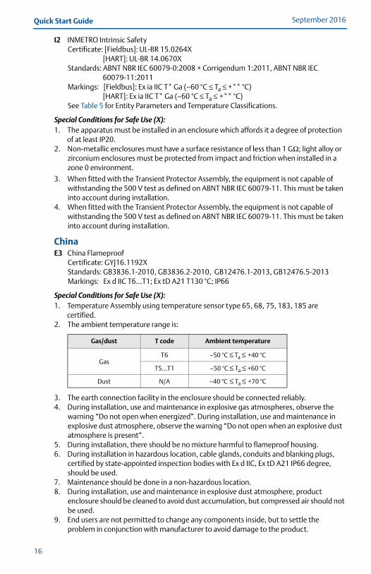
Special Conditions for Safe Use (X):1. Temperature Assembly using temperature sensor type 65, 68, 75, 183, 185 are
certified.2. The ambient temperature range is:
3. The earth connection facility in the enclosure should be connected reliably.4. During installation, use and maintenance in explosive gas atmospheres, observe the
warning “Do not open when energized”. During installation, use and maintenance in explosive dust atmosphere, observe the warning “Do not open when an explosive dust atmosphere is present”.
5. During installation, there should be no mixture harmful to flameproof housing.6. During installation in hazardous location, cable glands, conduits and blanking plugs,
certified by state-appointed inspection bodies with Ex d IIC, Ex tD A21 IP66 degree, should be used.
7. Maintenance should be done in a non-hazardous location.8. During installation, use and maintenance in explosive dust atmosphere, product
enclosure should be cleaned to avoid dust accumulation, but compressed air should not be used.
9. End users are not permitted to change any components inside, but to settle the problem in conjunction with manufacturer to avoid damage to the product.
Gas/dust T code Ambient temperature
GasT6 –50 °C ≤ Ta ≤ +40 °C
T5…T1 –50 °C ≤ Ta ≤ +60 °C
Dust N/A –40 °C ≤ Ta ≤ +70 °C
16
Quick Start GuideSeptember 2016
00825-0300-4728_RevCA.fm Page 17 Tuesday, September 13, 2016 4:22 PM
10. During installation, use and maintenance of this product, observe the following standards:GB3836.13-2013 “Electrical apparatus for explosive gas atmospheres Part 13: Repair and overhaul for apparatus used in explosive gas atmospheres”GB3836.15-2000 “Electrical apparatus for explosive gas atmospheres Part 15: Electrical installations in hazardous area (other than mines)”GB3836.16-2006 “Electrical apparatus for explosive gas atmospheres Part 16: Inspection and maintenance of electrical installation (other than mines)”GB50257-2014 “Code for construction and acceptance of electric device for explosion atmospheres and fire hazard electrical equipment installation engineering”.GB15577-2007 “Safe regulation for explosive dust atmospheres”GB12476.2-2010 “Electrical apparatus for use in the presence of combustible dust Part 1-2: Electrical apparatus protected by enclosures and surface temperature limitation-Selection, installation and maintenance”
I3 China Intrinsic SafetyCertificate: GYJ16.1191XStandards: GB3836.1-2010, GB3836.4-2010, GB3836.20-1010Markings: Ex ia IIC T4~T6 Ga
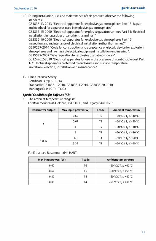
Special Conditions for Safe Use (X):1. The ambient temperature range is:
For Rosemount 644 Fieldbus, PROFIBUS, and Legacy 644 HART:
For Enhanced Rosemount 644 HART:
Transmitter output Max input power: (W) T code Ambient temperature
A
0.67 T6 –60 °C ≤ Ta ≤ +40 °C
0.67 T5 –60 °C ≤ Ta ≤ +50 °C
1 T5 –60 °C ≤ Ta ≤ +40 °C
1 T4 –60 °C ≤ Ta ≤ +80 °C
F or W1.3 T4 –50 °C ≤ Ta ≤ +60 °C
5.32 T4 –50 °C ≤ Ta ≤ +60 °C
Max input power: (W) T code Ambient temperature
0.67 T6 –60 °C ≤ Ta ≤ +40 °C
0.67 T5 –60 °C ≤ Ta ≤ +50 °C
0.80 T5 –60 °C ≤ Ta ≤ +40 °C
0.80 T4 –60 °C ≤ Ta ≤ +80 °C
17
September 2016Quick Start Guide
00825-0300-4728_RevCA.fm Page 18 Tuesday, September 13, 2016 4:22 PM
18
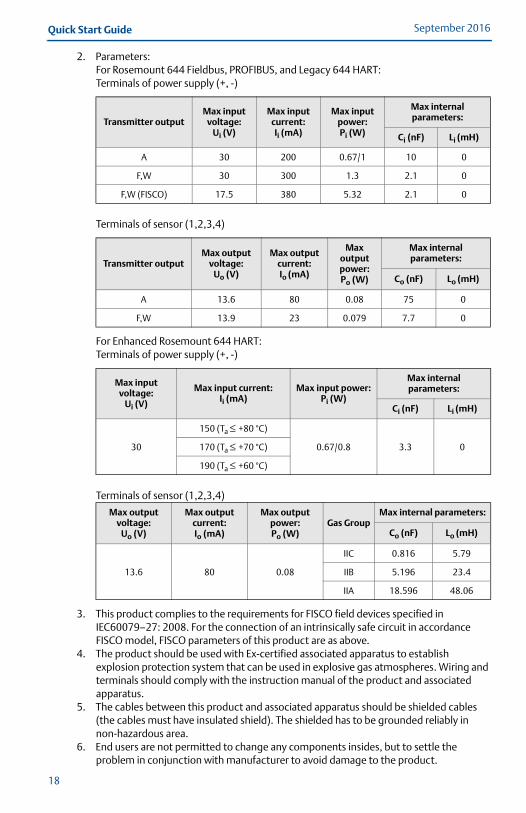
2. Parameters:For Rosemount 644 Fieldbus, PROFIBUS, and Legacy 644 HART: Terminals of power supply (+, -)
Terminals of sensor (1,2,3,4)
For Enhanced Rosemount 644 HART:Terminals of power supply (+, -)
Terminals of sensor (1,2,3,4)
3. This product complies to the requirements for FISCO field devices specified in IEC60079–27: 2008. For the connection of an intrinsically safe circuit in accordance FISCO model, FISCO parameters of this product are as above.
4. The product should be used with Ex-certified associated apparatus to establish explosion protection system that can be used in explosive gas atmospheres. Wiring and terminals should comply with the instruction manual of the product and associated apparatus.
5. The cables between this product and associated apparatus should be shielded cables (the cables must have insulated shield). The shielded has to be grounded reliably in non-hazardous area.
6. End users are not permitted to change any components insides, but to settle the problem in conjunction with manufacturer to avoid damage to the product.
Transmitter outputMax input
voltage:Ui (V)
Max input current:Ii (mA)
Max input power:Pi (W)
Max internal parameters:
Ci (nF) Li (mH)
A 30 200 0.67/1 10 0
F,W 30 300 1.3 2.1 0
F,W (FISCO) 17.5 380 5.32 2.1 0
Transmitter outputMax output
voltage:Uo (V)
Max output current:Io (mA)
Max output power:Po (W)
Max internal parameters:
Co (nF) Lo (mH)
A 13.6 80 0.08 75 0
F,W 13.9 23 0.079 7.7 0
Max input voltage:
Ui (V)
Max input current:Ii (mA)
Max input power:Pi (W)
Max internal parameters:
Ci (nF) Li (mH)
30
150 (Ta ≤ +80 °C)
0.67/0.8 3.3 0170 (Ta ≤ +70 °C)
190 (Ta ≤ +60 °C)
Max output voltage:
Uo (V)
Max output current:Io (mA)
Max output power:Po (W)
Gas GroupMax internal parameters:
Co (nF) Lo (mH)
13.6 80 0.08
IIC 0.816 5.79
IIB 5.196 23.4
IIA 18.596 48.06
Quick Start GuideSeptember 2016
00825-0300-4728_RevCA.fm Page 19 Tuesday, September 13, 2016 4:22 PM
7. During installation, use and maintenance of this product, observe the following standards:GB3836.13-2013 “Electrical apparatus for explosive gas atmospheres Part 13: Repair and overhaul for apparatus used in explosive gas atmospheres”GB3836.15-2000 “Electrical apparatus for explosive gas atmospheres Part 15: Electrical installations in hazardous area (other than mines)”GB3836.16-2006 “Electrical apparatus for explosive gas atmospheres Part 16: Inspection and maintenance of electrical installation (other than mines)”GB3836.18-2010 “Explosive Atmospheres” Part 18: Intrinsically safe systemsGB50257-2014 “Code for construction and acceptance of electric device for explosion atmospheres and fire hazard electrical equipment installation engineering”.
N3 China Type nCertificate: GYJ15.1502Standards: GB3836.1-2000, GB3836.8-2003Markings: Ex nA IIC T5/T6 Gc
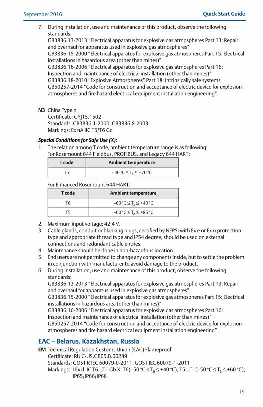
Special Conditions for Safe Use (X):1. The relation among T code, ambient temperature range is as following:
For Rosemount 644 Fieldbus, PROFIBUS, and Legacy 644 HART:
For Enhanced Rosemount 644 HART:
2. Maximum input voltage: 42.4 V.3. Cable glands, conduit or blanking plugs, certified by NEPSI with Ex e or Ex n protection
type and appropriate thread type and IP54 degree, should be used on external connections and redundant cable entries.
4. Maintenance should be done in non-hazardous location.5. End users are not permitted to change any components inside, but to settle the problem
in conjunction with manufacturer to avoid damage to the product.6. During installation, use and maintenance of this product, observe the following
standards:GB3836.13-2013 “Electrical apparatus for explosive gas atmospheres Part 13: Repair and overhaul for apparatus used in explosive gas atmospheres”GB3836.15-2000 “Electrical apparatus for explosive gas atmospheres Part 15: Electrical installations in hazardous area (other than mines)”GB3836.16-2006 “Electrical apparatus for explosive gas atmospheres Part 16: Inspection and maintenance of electrical installation (other than mines)”GB50257-2014 “Code for construction and acceptance of electric device for explosion atmospheres and fire hazard electrical equipment installation engineering”
EAC – Belarus, Kazakhstan, RussiaEM Technical Regulation Customs Union (EAC) Flameproof
Certificate: RU C-US.GB05.B.00289Standards: GOST R IEC 60079-0-2011, GOST IEC 60079-1-2011Markings: 1Ex d IIC T6…T1 Gb X, T6(–50 °C ≤ Ta ≤ +40 °C), T5…T1(–50 °C ≤ Ta ≤ +60 °C);
IP65/IP66/IP68
T code Ambient temperature
T5 –40 °C ≤ Ta ≤ +70 °C
T code Ambient temperature
T6 –60 °C ≤ Ta ≤ +40 °C
T5 –60 °C ≤ Ta ≤ +85 °C
19
September 2016Quick Start Guide
00825-0300-4728_RevCA.fm Page 20 Tuesday, September 13, 2016 4:22 PM
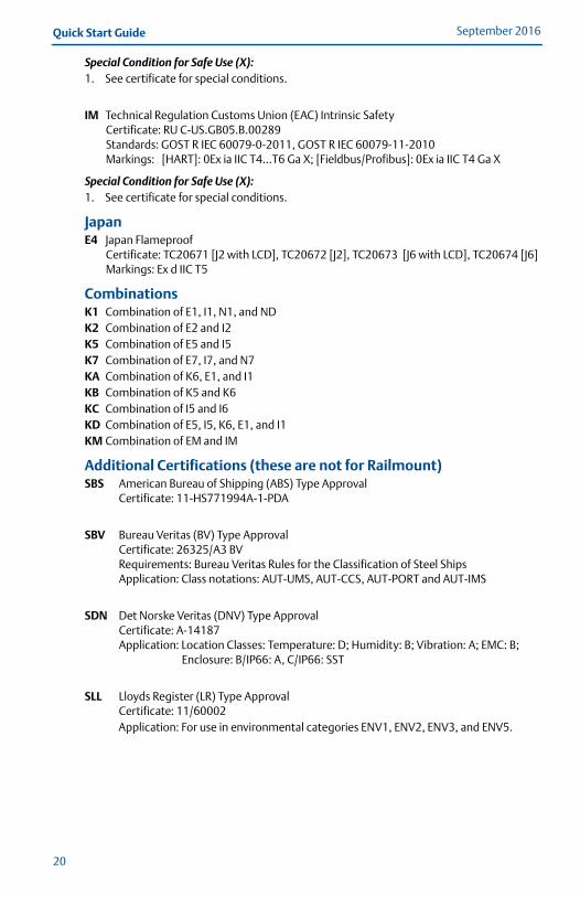
Special Condition for Safe Use (X):1. See certificate for special conditions.
IM Technical Regulation Customs Union (EAC) Intrinsic SafetyCertificate: RU C-US.GB05.B.00289Standards: GOST R IEC 60079-0-2011, GOST R IEC 60079-11-2010Markings: [HART]: 0Ex ia IIC T4…T6 Ga X; [Fieldbus/Profibus]: 0Ex ia IIC T4 Ga X
Special Condition for Safe Use (X):1. See certificate for special conditions.
JapanE4 Japan Flameproof
Certificate: TC20671 [J2 with LCD], TC20672 [J2], TC20673 [J6 with LCD], TC20674 [J6]Markings: Ex d IIC T5
CombinationsK1 Combination of E1, I1, N1, and NDK2 Combination of E2 and I2K5 Combination of E5 and I5K7 Combination of E7, I7, and N7KA Combination of K6, E1, and I1KB Combination of K5 and K6KC Combination of I5 and I6KD Combination of E5, I5, K6, E1, and I1KM Combination of EM and IM
Additional Certifications (these are not for Railmount)SBS American Bureau of Shipping (ABS) Type Approval
Certificate: 11-HS771994A-1-PDA
SBV Bureau Veritas (BV) Type ApprovalCertificate: 26325/A3 BVRequirements: Bureau Veritas Rules for the Classification of Steel ShipsApplication: Class notations: AUT-UMS, AUT-CCS, AUT-PORT and AUT-IMS
SDN Det Norske Veritas (DNV) Type ApprovalCertificate: A-14187Application: Location Classes: Temperature: D; Humidity: B; Vibration: A; EMC: B;
Enclosure: B/IP66: A, C/IP66: SST
SLL Lloyds Register (LR) Type ApprovalCertificate: 11/60002Application: For use in environmental categories ENV1, ENV2, ENV3, and ENV5.
20
Quick Start GuideSeptember 2016
00825-0300-4728_RevCA.fm Page 21 Tuesday, September 13, 2016 4:22 PM
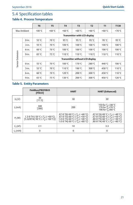
5.4 Specification tablesTable 4. Process Temperature
T6 T5 T4 T3 T2 T1 T130
Max Ambient +40 °C +60 °C +60 °C +60 °C +60 °C +60 °C +70 °C
Transmitter with LCD display
Sens
or E
xten
sion
0-in. 55 °C 70 °C 95 °C 95 °C 95 °C 95 °C 95 °C
3-in. 55 °C 70 °C 100 °C 100 °C 100 °C 100 °C 100 °C
6-in. 60 °C 70 °C 100 °C 100 °C 100 °C 100 °C 100 °C
9-in. 65 °C 75 °C 110 °C 110 °C 110 °C 110 °C 110 °C
Transmitter without LCD display
0-in. 55 °C 70 °C 100 °C 170 °C 280 °C 440 °C 100 °C
3-in. 55 °C 70 °C 110 °C 190 °C 300 °C 450 °C 110 °C
6-in. 60 °C 70 °C 120 °C 200 °C 300 °C 450 °C 110 °C
9-in. 65 °C 75 °C 130 °C 200 °C 300 °C 450 °C 120 °C
Table 5. Entity Parameters
Fieldbus/PROFIBUS[FISCO] HART HART (Enhanced)
Ui (V) 30[17.5] 30 30
Ii (mA) 300[380] 200
150 for Ta ≤ 80 °C170 for Ta ≤70 °C190 for Ta ≤60 °C
Pi (W) 1.3 @ T4 (-50 °C ≤ Ta ≤ +60 °C)[5.32@T4(-50 °C ≤ Ta ≤ +60 °C)]
.67 @ T6(-60 °C ≤ Ta ≤ +40 °C)
.67 @ T5(-60 °C ≤ Ta ≤ +50 °C)1.0 @ T5(-60 °C ≤ Ta ≤ +40 °C)1.0 @ T4(-60 °C ≤ Ta ≤ +80 °C)
.67 @ T6(-60 °C ≤ Ta ≤ +40 °C)
.67 @ T5(-60 °C ≤ Ta ≤ +50 °C)
.80 @ T5(-60 °C ≤ Ta ≤ +40 °C)
.80 @ T4(-60 °C ≤ Ta ≤ +80 °C)
Ci (nF) 2.1 10 3.3
Li (mH) 0 0 0
21
September 2016Quick Start Guide
00825-0300-4728_RevCA.fm Page 22 Tuesday, September 13, 2016 4:22 PM
Figure 3. Rosemount 644 Declaration of Conformity
22
Quick Start GuideSeptember 2016
00825-0300-4728_RevCA.fm Page 23 Tuesday, September 13, 2016 4:22 PM
23
September 2016Quick Start Guide
00825-0300-4728_RevCA.fm Page 24 Tuesday, September 13, 2016 4:22 PM
24
Quick Start GuideSeptember 2016
00825-0300-4728_RevCA.fm Page 25 Tuesday, September 13, 2016 4:22 PM
25
September 2016Quick Start Guide
00825-0300-4728_RevCA.fm Page 26 Tuesday, September 13, 2016 4:22 PM
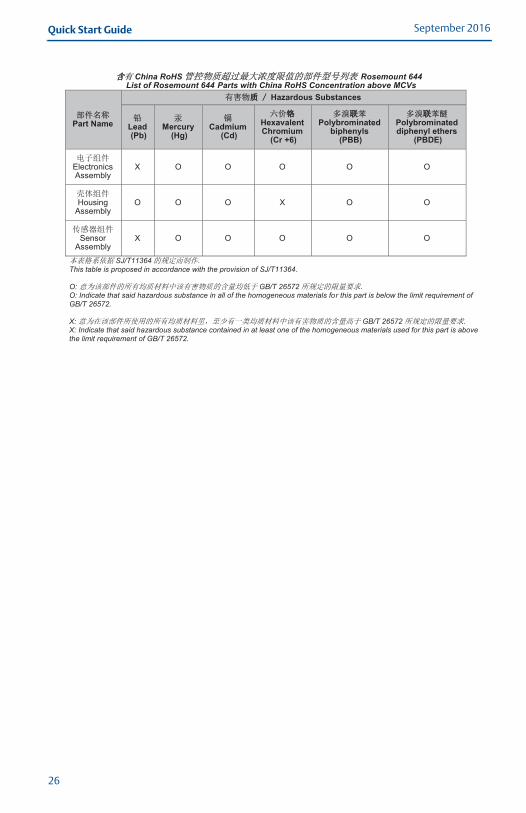
China RoHS Rosemount 644
List of Rosemount 644 Parts with China RoHS Concentration above MCVs
Part Name
Hazardous Substances
Lead (Pb)
Mercury (Hg)
Cadmium (Cd)
Hexavalent Chromium
(Cr +6)
Polybrominated biphenyls
(PBB)
Polybrominated diphenyl ethers
(PBDE)
Electronics Assembly
X O O O O O
Housing Assembly
O O O X O O
Sensor Assembly
X O O O O O
SJ/T11364This table is proposed in accordance with the provision of SJ/T11364. O: GB/T 26572 O: Indicate that said hazardous substance in all of the homogeneous materials for this part is below the limit requirement of GB/T 26572. X: GB/T 26572 X: Indicate that said hazardous substance contained in at least one of the homogeneous materials used for this part is above the limit requirement of GB/T 26572.
26

Quick Start GuideSeptember 2016
00825-0300-4728_RevCA.fm Page 27 Tuesday, September 13, 2016 4:22 PM
27

00825-0300-4728_RevCA.fm Page 28 Tuesday, September 13, 2016 4:22 PM
Global HeadquartersEmerson Process Management 6021 Innovation Blvd.Shakopee, MN 55379, USA
+1 800 999 9307 or +1 952 906 8888+1 952 949 7001 [email protected]
North America Regional OfficeEmerson Process Management 8200 Market Blvd.Chanhassen, MN 55317, USA
+1 800 999 9307 or +1 952 906 8888
+1 952 949 7001
Latin America Regional OfficeEmerson Process Management 1300 Concord Terrace, Suite 400Sunrise, FL 33323, USA
+1 954 846 5030
+1 954 846 5121
Linkedin.com/company/Emerson-Process-Management
Twitter.com/Rosemount_News
Facebook.com/Rosemount
Youtube.com/user/RosemountMeasurement
Google.com/+RosemountMeasurement
Standard Terms and Conditions of Sale can be found at www.Emerson.com/en-us/pages/Terms-of-Use.aspxThe Emerson logo is a trademark and service mark of Emerson Electric Co.Rosemount and Rosemount logotype are trademarks of Emerson Process Management.HART is a registered trademark of FieldComm Group.PROFIBUS is a registered trademark of PROFINET International (PI).NEMA is a registered trademark and service mark of the National Electrical Manufacturers Association.National Electrical Code is a registered trademark of National Fire Protection Association, Inc.All other marks are the property of their respective owners.© 2016 Emerson Process Management. All rights reserved.
Europe Regional OfficeEmerson Process Management Europe GmbHNeuhofstrasse 19a P.O. Box 1046CH 6340 BaarSwitzerland
+41 (0) 41 768 6111
+41 (0) 41 768 6300
Asia Pacific Regional OfficeEmerson Process Management Asia Pacific Pte Ltd1 Pandan CrescentSingapore 128461
+65 6777 8211
+65 6777 0947 [email protected]
Middle East and Africa Regional OfficeEmerson Process Management Emerson FZE P.O. Box 17033,Jebel Ali Free Zone - South 2Dubai, United Arab Emirates
+971 4 8118100
+971 4 [email protected]
Quick Start Guide00825-0300-4728, Rev CA
September 2016
*00825-0300-4728*