Embed Size (px)
Citation preview
Product Data Sheet00813-0100-4016, Rev JAApril 2010 Rosemount DP Level
Rosemount DP Level Transmitters and Remote Seals
FOR ROSEMOUNT 3051S, 3051, AND 2051 TRANSMITTERSAPPLICATIONS
• Level, Flow, Pressure, Interface, Density
• Extreme hot and cold temperatures
• Corrosive, clogging, or viscous processes
• Hygienic requirements
• Special process connections
ContentsProven, Reliable, and Innovative DP Level Technologies . . . . . . . . . . . . . . . . . . . . . page 2
Ordering Information
Rosemount 3051S Liquid Level Transmitter . . . . . . . . . . . . . . . . . . . . . . . . . . page 4
Rosemount 3051L Liquid Level Transmitter . . . . . . . . . . . . . . . . . . . . . . . . . page 11
www.ro
Rosemount 2051L Liquid Level Transmitter . . . . . . . . . . . . . . . . . . . . . . . . . page 16
Rosemount 1199 Direct Mount Seal Systems. . . . . . . . . . . . . . . . . . . . . . . . page 21
Rosemount 1199 Remote Mount Seal Systems . . . . . . . . . . . . . . . . . . . . . . page 26
Flanged Seal Assemblies . . . . . . . . . . . . . . . . . . . . . . . . . . . . . . . . . . . . . . . page 32
Threaded Seal Assemblies . . . . . . . . . . . . . . . . . . . . . . . . . . . . . . . . . . . . . . page 47
Hygienic Seal Assemblies . . . . . . . . . . . . . . . . . . . . . . . . . . . . . . . . . . . . . . . page 51
Specialty Seal Assemblies . . . . . . . . . . . . . . . . . . . . . . . . . . . . . . . . . . . . . . page 59
Specifications . . . . . . . . . . . . . . . . . . . . . . . . . . . . . . . . . . . . . . . . . . . . . . . . . . . . . page 64
Product Certifications . . . . . . . . . . . . . . . . . . . . . . . . . . . . . . . . . . . . . . . . . . . . . . . page 74
Dimensional Drawings. . . . . . . . . . . . . . . . . . . . . . . . . . . . . . . . . . . . . . . . . . . . . . . page 87
semount.com
Product Data Sheet00813-0100-4016, Rev JA
April 2010Rosemount DP Level
2
Proven, Reliable, and Innovative DP Level Technologies
To meet your application requirements, the combination of Rosemount level transmitters and remote seals deliver an unsurpassed product offering that is easy to specify, order, and install. The Rosemount 1199 offering defined in this product data sheet highlights the wide variety of process connections, direct mount or capillary connections, and materials of construction to address almost any application. If you don’t see what you need listed here, ask us. We can create a custom engineered solution to meet your needs.
WHAT IS A SEAL SYSTEM?
A diaphragm seal system consists of a pressure transmitter, one or two diaphragm seals, a fill fluid, and either a direct mount or capillary style connection.
During operation, the thin, flexible diaphragm and fill fluid separate the pressure sensing element of the transmitter from the process medium. The capillary tubing or direct mount flange connects the diaphragm to the transmitter.
When process pressure is applied, the diaphragm is displaced, transferring the measured pressure through the filled system, through the capillary tubing, to the transmitter element. This transferred pressure displaces the sensing diaphragm of the pressure transmitter. This displacement is proportional to the process pressure and is converted electronically to an appropriate 4-20 mA, digital HART, or FOUNDATION fieldbus output signal.
WHY USE DIAPHRAGM SEALS?
Seal systems provide a reliable process pressure measurement and prevent the process medium from contacting the transmitter diaphragm.
Transmitter/diaphragm seal systems should be considered when:
• The process temperature is outside of the normal operating ranges of the transmitter and cannot be brought into those limits with impulse piping.
• The process is corrosive and would require frequent transmitter replacement or specific exotic materials of construction.
• The process contains suspended solids or is viscous and may plug the impulse piping.
• The application requires the use of Hygienic connections.
• There is a need for easier cleaning of the process from the connections to avoid contamination between batches.
• There is a need to replace wet/ dry legs to reduce maintenance on applications where the reference leg is not stable or often needs to be refilled/drained.
• There is a need to make density or interface measurements.
• The process medium may freeze or solidify in the transmitter or impulse piping.
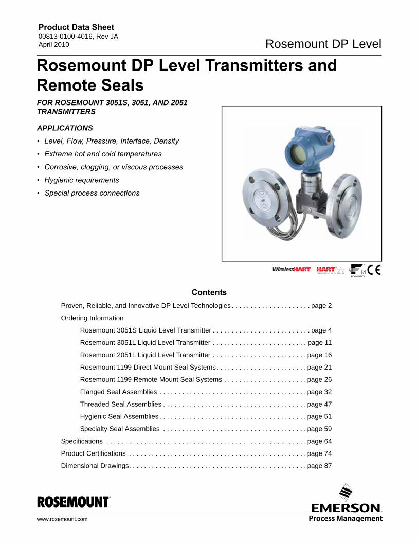
Proven Best Practices Deliver Tuned-System™ Assemblies for DP-Level Installations• Reduced installed cost by 20% by eliminating excess capillary and
transmitter mounting hardware
• Reduced risk with up-front quantified performance reports
• Improved performance by 30%
• Time response improved by over 80%
Balanced System Tuned-System Assemblies
Product Data Sheet00813-0100-4016, Rev JAApril 2010 Rosemount DP Level
3
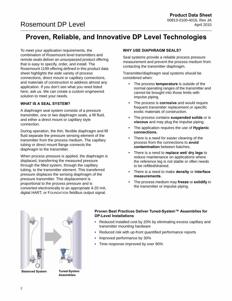
Rosemount 3051S_L, 3051L, and 2051L Liquid Level Transmitters
• Welded system provides best-in-class system reliability
• Flush, 2-in. (50 mm), 4-in. (100 mm), and 6-in. (150 mm) extended diaphragms
• Multiple fill fluids and wetted materials available
• Level and volume units, process alerts
Reliable System Construction that is 100% Helium Leak Tested
• Most flexible offering with Tuned-System Assemblies, Balanced System Assemblies, direct mount, capillary, and Thermal Optimizer construction
• Capillary ID sizes: 0.03–in. (0.7 mm), 0.04–in. (1.1 mm), and 0.07–in. (1.75 mm)
• Welded-repairable construction is the industry leading, robust design for most applications.
• All Welded construction designed for high temperature and high vacuum (below 6 psi-a or 414 mbar-a) applications.
• Thermal Optimizer designed for high process temperature and cold ambient temperature applications
• Most variety of fill fluids that meets industry and hygienic applications
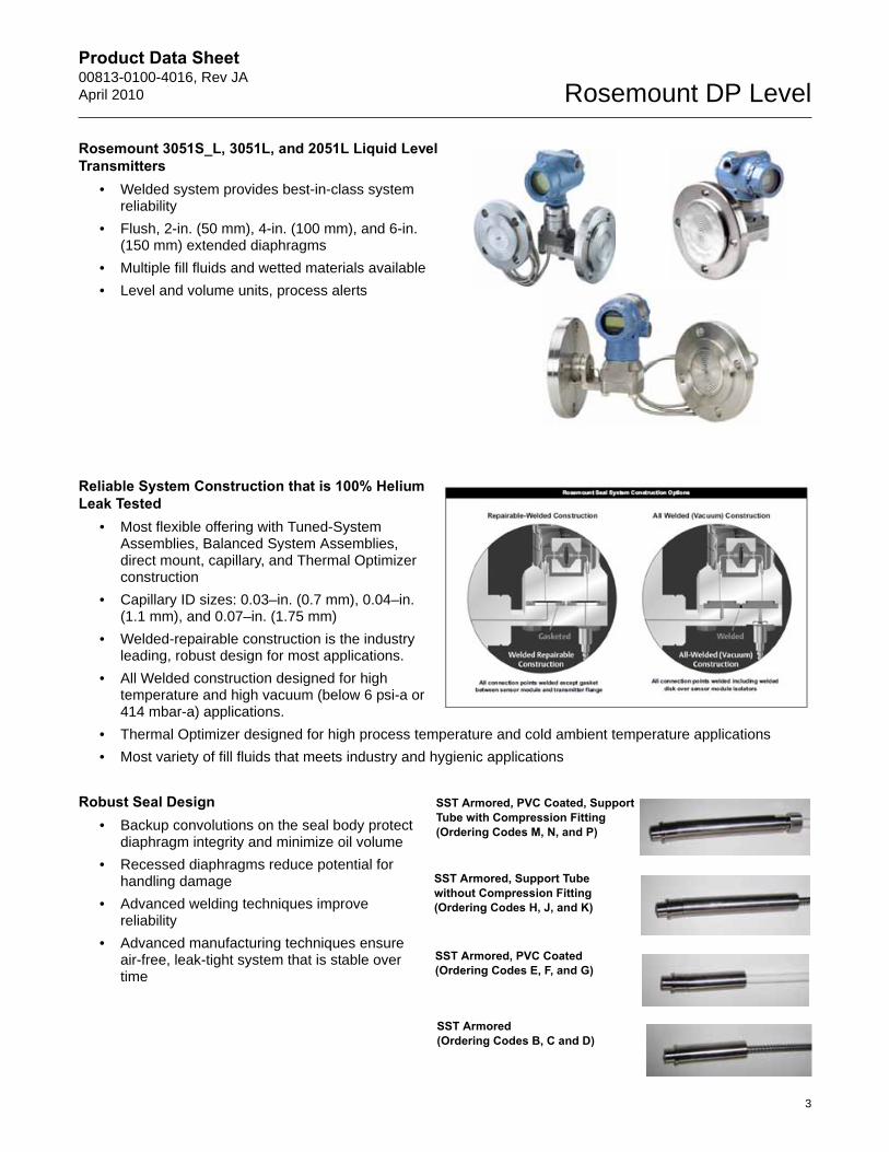
Robust Seal Design• Backup convolutions on the seal body protect
diaphragm integrity and minimize oil volume
• Recessed diaphragms reduce potential for handling damage
• Advanced welding techniques improve reliability
• Advanced manufacturing techniques ensure air-free, leak-tight system that is stable over time
SST Armored, PVC Coated, Support Tube with Compression Fitting (Ordering Codes M, N, and P)
SST Armored, Support Tube without Compression Fitting (Ordering Codes H, J, and K)
SST Armored, PVC Coated (Ordering Codes E, F, and G)
SST Armored (Ordering Codes B, C and D)

Product Data Sheet00813-0100-4016, Rev JA
April 2010Rosemount DP Level
Rosemount 3051S Liquid Level Transmitter
Rosemount 3051S Liquid Level transmitters combine the scalable features and benefits of a high-performance 3051S transmitter with the durability and reliability of a direct mount seal all in a single model number.
Level transmitters can also be ordered with an additional 1199 remote seal to form a Tuned-System Assembly that offers improved performance and reduced costs compared to traditional symmetrical (balanced) assemblies.
Product features and capabilities include:
• Variety of process connections
• Quantified performance for the entire transmitter / seal assembly (QZ option)
• 4-20 mA HART®, FOUNDATION™ fieldbus, and WirelessHART™ protocols
Additional InformationSpecifications: page 64Certifications: page 74Dimensional Drawings: page 87
3051S Liquid Level Transmitter
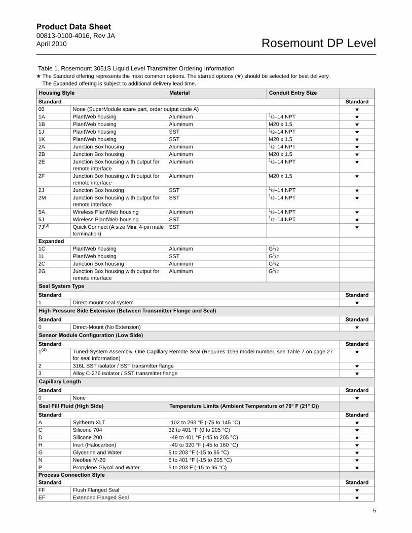
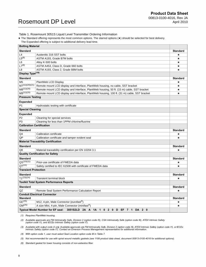
Table 1. Rosemount 3051S Liquid Level Transmitter Ordering Information★ The Standard offering represents the most common options. The starred options (★) should be selected for best delivery.__The Expanded offering is subject to additional delivery lead time.
Model Transmitter Type3051S Liquid Level Transmitter
Performance ClassStandard Standard1 Ultra: 0.065% span accuracy, 100:1 rangedown, 12-year limited warranty ★
2 Classic: 0.065% span accuracy, 100:1 rangedown ★
Connection TypeStandard StandardL Level ★
Measurement TypeStandard StandardD Differential ★
G Gage ★
A Absolute ★
Pressure Range
Differential (LD) Gage (LG) Absolute (LA)Standard Standard2A -250 to 250 inH2O (-623 to 623 mbar) -250 to 250 inH2O (-623 to 623 mbar) 0 to 150 psia (10 bar) ★
3A -1000 to 1000 inH2O (-2,5 to 2,5 bar) -393 to 1000 inH2O (-0,98 to 2,5 bar) 0 to 800 psia (55 bar) ★
4A -300 to 300 psi (-20,7 to 20,7 bar) -14.2 to 300 psig (-0,98 to 21 bar) 0 to 4000 psia (276 bar) ★
5A -2000 to 2000 psi (-137,9 to 137,9 bar) -14.2 to 2000 psig (-0,98 to 137,9 bar) N/A ★
Transmitter OutputStandard StandardA 4-20 mA with digital signal based on HART protocol ★
F(1) FOUNDATION fieldbus protocol ★
X(2) Wireless (Requires wireless options and wireless PlantWeb housing) ★
4
Product Data Sheet00813-0100-4016, Rev JAApril 2010 Rosemount DP Level
Housing Style Material Conduit Entry SizeStandard Standard00 None (SuperModule spare part, order output code A) ★
1A PlantWeb housing Aluminum 1/2–14 NPT ★
1B PlantWeb housing Aluminum M20 x 1.5 ★
1J PlantWeb housing SST 1/2–14 NPT ★
1K PlantWeb housing SST M20 x 1.5 ★
2A Junction Box housing Aluminum 1/2–14 NPT ★
2B Junction Box housing Aluminum M20 x 1.5 ★
2E Junction Box housing with output for remote interface
Aluminum 1/2–14 NPT ★
2F Junction Box housing with output for remote interface
Aluminum M20 x 1.5 ★
2J Junction Box housing SST 1/2–14 NPT ★
2M Junction Box housing with output for remote interface
SST 1/2–14 NPT ★
5A Wireless PlantWeb housing Aluminum 1/2–14 NPT ★
5J Wireless PlantWeb housing SST 1/2–14 NPT ★
7J(3) Quick Connect (A size Mini, 4-pin male termination)
SST ★
Expanded1C PlantWeb housing Aluminum G1/2
1L PlantWeb housing SST G1/2
2C Junction Box housing Aluminum G1/2
2G Junction Box housing with output for remote interface
Aluminum G1/2
Seal System TypeStandard Standard1 Direct-mount seal system ★
High Pressure Side Extension (Between Transmitter Flange and Seal)Standard Standard0 Direct-Mount (No Extension) ★
Sensor Module Configuration (Low Side)Standard Standard1(4) Tuned-System Assembly, One Capillary Remote Seal (Requires 1199 model number, see Table 7 on page 27
for seal information)★
2 316L SST isolator / SST transmitter flange ★
3 Alloy C-276 isolator / SST transmitter flange ★
Capillary LengthStandard Standard0 None ★
Seal Fill Fluid (High Side) Temperature Limits (Ambient Temperature of 70° F (21° C))Standard StandardA Syltherm XLT -102 to 293 °F (-75 to 145 °C) ★
C Silicone 704 32 to 401 °F (0 to 205 °C) ★
D Silicone 200 -49 to 401 °F (-45 to 205 °C) ★
H Inert (Halocarbon) -49 to 320 °F (-45 to 160 °C) ★
G Glycerine and Water 5 to 203 °F (-15 to 95 °C) ★
N Neobee M-20 5 to 401 °F (-15 to 205 °C) ★
P Propylene Glycol and Water 5 to 203 F (-15 to 95 °C) ★
Process Connection StyleStandard StandardFF Flush Flanged Seal ★
EF Extended Flanged Seal ★
Table 1. Rosemount 3051S Liquid Level Transmitter Ordering Information★ The Standard offering represents the most common options. The starred options (★) should be selected for best delivery.__The Expanded offering is subject to additional delivery lead time.
5
Product Data Sheet00813-0100-4016, Rev JAApril 2010 Rosemount DP Level
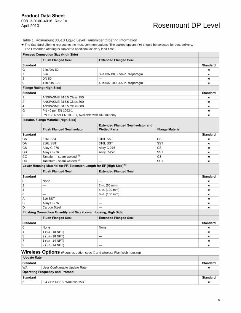
Process Connection Size (High Side)
Flush Flanged Seal Extended Flanged SealStandard StandardG 2-in./DN 50 — ★
7 3-in. 3-in./DN 80, 2.58-in. diaphragm ★
J DN 80 — ★
9 4-in./DN 100 4-in./DN 100, 3.5-in. diaphragm ★
Flange Rating (High Side)Standard Standard1 ANSI/ASME B16.5 Class 150 ★
2 ANSI/ASME B16.5 Class 300 ★
4 ANSI/ASME B16.5 Class 600 ★
G PN 40 per EN 1092-1 ★
E PN 10/16 per EN 1092-1, Available with DN 100 only ★
Isolator, Flange Material (High Side)
Flush Flanged Seal Isolator Extended Flanged Seal Isolator and Wetted Parts Flange Material
Standard StandardCA 316L SST 316L SST CS ★
DA 316L SST 316L SST SST ★
CB Alloy C-276 Alloy C-276 CS ★
DB Alloy C-276 Alloy C-276 SST ★
CC Tantalum - seam welded(5) — CS ★
DC Tantalum - seam welded(5) — SST ★
Lower Housing Material for FF, Extension Length for EF (High Side)(6)
Flush Flanged Seal Extended Flanged SealStandard Standard0 None — ★
2 — 2-in. (50 mm) ★
4 — 4-in. (100 mm) ★
6 — 6-in. (150 mm) ★
A 316 SST — ★
B Alloy C-276 — ★
D Carbon Steel — ★
Flushing Connection Quantity and Size (Lower Housing, High Side)
Flush Flanged Seal Extended Flanged SealStandard Standard0 None None ★
1 1 (1/4 - 18 NPT) — ★
3 2 (1/4 - 18 NPT) — ★
7 1 (1/2 - 14 NPT) — ★
9 2 (1/2 - 14 NPT) — ★
Wireless Options (Requires option code X and wireless PlantWeb housing)
Update Rate
Standard StandardWA User Configurable Update Rate ★
Operating Frequency and Protocol
Standard Standard3 2.4 GHz DSSS, WirelessHART ★
Table 1. Rosemount 3051S Liquid Level Transmitter Ordering Information★ The Standard offering represents the most common options. The starred options (★) should be selected for best delivery.__The Expanded offering is subject to additional delivery lead time.
6
Product Data Sheet00813-0100-4016, Rev JA
April 2010Rosemount DP Level
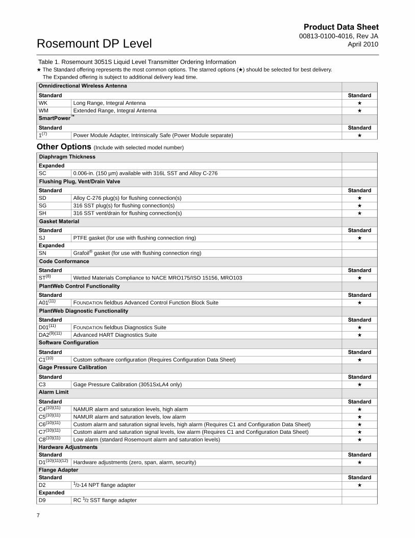
Omnidirectional Wireless Antenna
Standard StandardWK Long Range, Integral Antenna ★
WM Extended Range, Integral Antenna ★
SmartPower™
Standard Standard1(7) Power Module Adapter, Intrinsically Safe (Power Module separate) ★
Other Options (Include with selected model number)
Diaphragm ThicknessExpandedSC 0.006-in. (150 µm) available with 316L SST and Alloy C-276
Flushing Plug, Vent/Drain ValveStandard StandardSD Alloy C-276 plug(s) for flushing connection(s) ★
SG 316 SST plug(s) for flushing connection(s) ★
SH 316 SST vent/drain for flushing connection(s) ★
Gasket MaterialStandard StandardSJ PTFE gasket (for use with flushing connection ring) ★
ExpandedSN Grafoil® gasket (for use with flushing connection ring)
Code ConformanceStandard StandardST(8) Wetted Materials Compliance to NACE MRO175/ISO 15156, MRO103 ★
PlantWeb Control FunctionalityStandard StandardA01(11) FOUNDATION fieldbus Advanced Control Function Block Suite ★
PlantWeb Diagnostic FunctionalityStandard StandardD01(11) FOUNDATION fieldbus Diagnostics Suite ★
DA2(9)(11) Advanced HART Diagnostics Suite ★
Software Configuration
Standard StandardC1(10) Custom software configuration (Requires Configuration Data Sheet) ★
Gage Pressure Calibration
Standard StandardC3 Gage Pressure Calibration (3051SxLA4 only) ★
Alarm Limit
Standard StandardC4(10)(11) NAMUR alarm and saturation levels, high alarm ★
C5(10)(11) NAMUR alarm and saturation levels, low alarm ★
C6(10)(11) Custom alarm and saturation signal levels, high alarm (Requires C1 and Configuration Data Sheet) ★
C7(10)(11) Custom alarm and saturation signal levels, low alarm (Requires C1 and Configuration Data Sheet) ★
C8(10)(11) Low alarm (standard Rosemount alarm and saturation levels) ★
Hardware AdjustmentsStandard StandardD1(10)(11)(12) Hardware adjustments (zero, span, alarm, security) ★
Flange AdapterStandard StandardD2 1/2-14 NPT flange adapter ★
ExpandedD9 RC 1/2 SST flange adapter
Table 1. Rosemount 3051S Liquid Level Transmitter Ordering Information★ The Standard offering represents the most common options. The starred options (★) should be selected for best delivery.__The Expanded offering is subject to additional delivery lead time.
7
Product Data Sheet00813-0100-4016, Rev JAApril 2010 Rosemount DP Level
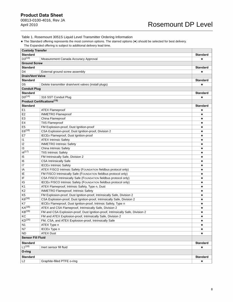
Custody TransferStandard StandardD3(13) Measurement Canada Accuracy Approval ★
Ground Screw Standard StandardD4 External ground screw assembly ★
Drain/Vent ValveStandard StandardD5 Delete transmitter drain/vent valves (install plugs) ★
Conduit PlugStandard StandardD0(14) 316 SST Conduit Plug ★
Product Certifications(15)
Standard StandardE1 ATEX Flameproof ★
E2 INMETRO Flameproof ★
E3 China Flameproof ★
E4 TIIS Flameproof ★
E5 FM Explosion-proof, Dust Ignition-proof ★
E6(16) CSA Explosion-proof, Dust Ignition-proof, Division 2 ★
E7 IECEx Flameproof, Dust Ignition-proof ★
I1 ATEX Intrinsic Safety ★
I2 INMETRO Intrinsic Safety ★
I3 China Intrinsic Safety ★
I4(17) TIIS Intrinsic Safety ★
I5 FM Intrinsically Safe, Division 2 ★
I6 CSA Intrinsically Safe ★
I7 IECEx Intrinsic Safety ★
IA ATEX FISCO Intrinsic Safety (FOUNDATION fieldbus protocol only) ★
IE FM FISCO Intrinsically Safe (FOUNDATION fieldbus protocol only) ★
IF CSA FISCO Intrinsically Safe (FOUNDATION fieldbus protocol only) ★
IG IECEx FISCO Intrinsic Safety (FOUNDATION fieldbus protocol only) ★
K1 ATEX Flameproof, Intrinsic Safety, Type n, Dust ★
K2 INMETRO Flameproof, Intrinsic Safety ★
K5 FM Explosion-proof, Dust Ignition-proof, Intrinsically Safe, Division 2 ★
K6(16) CSA Explosion-proof, Dust Ignition-proof, Intrinsically Safe, Division 2 ★
K7 IECEx Flameproof, Dust Ignition-proof, Intrinsic Safety, Type n ★
KA(16) ATEX and CSA Flameproof, Intrinsically Safe, Division 2 ★
KB(16) FM and CSA Explosion-proof, Dust Ignition-proof, Intrinsically Safe, Division 2 ★
KC FM and ATEX Explosion-proof, Intrinsically Safe, Division 2 ★
KD(16) FM, CSA, and ATEX Explosion-proof, Intrinsically Safe ★
N1 ATEX Type n ★
N7 IECEx Type n ★
ND ATEX Dust ★
Sensor Fill Fluid
Standard StandardL1(18) Inert sensor fill fluid ★
O-ring
Standard StandardL2 Graphite-filled PTFE o-ring ★
Table 1. Rosemount 3051S Liquid Level Transmitter Ordering Information★ The Standard offering represents the most common options. The starred options (★) should be selected for best delivery.__The Expanded offering is subject to additional delivery lead time.
8
Product Data Sheet00813-0100-4016, Rev JA
April 2010Rosemount DP Level
Bolting Material
Standard StandardL4 Austenitic 316 SST bolts ★
L5(8) ASTM A193, Grade B7M bolts ★
L6 Alloy K-500 bolts ★
L7(8) ASTM A453, Class D, Grade 660 bolts ★
L8 ASTM A193, Class 2, Grade B8M bolts ★
Display Type(19)
Standard StandardM5 PlantWeb LCD Display ★
M7(11)(20)(21) Remote mount LCD display and interface, PlantWeb housing, no cable, SST bracket ★
M8(11)(20) Remote mount LCD display and interface, PlantWeb housing, 50 ft. (15 m) cable, SST bracket ★
M9(11)(20) Remote mount LCD display and interface, PlantWeb housing, 100 ft. (31 m) cable, SST bracket ★
Pressure Testing
ExpandedP1 Hydrostatic testing with certificate
Special Cleaning
ExpandedP2 Cleaning for special servicesP3 Cleaning for less than 1PPM chlorine/fluorine
Calibration Certification
Standard StandardQ4 Calibration certificate ★
QP Calibration certificate and tamper evident seal ★
Material Traceability Certification
Standard StandardQ8 Material traceability certification per EN 10204 3.1 ★
Quality Certification for Safety
Standard StandardQS(10)(11) Prior-use certificate of FMEDA data ★
QT(22) Safety certified to IEC 61508 with certificate of FMEDA data ★
Transient Protection
Standard StandardT1(23)(24) Transient terminal block ★
Toolkit Total System Performance Reports
Standard StandardQZ Remote Seal System Performance Calculation Report ★
Conduit Electrical ConnectorStandard StandardGE(25) M12, 4-pin, Male Connector (eurofast®) ★
GM(25) A size Mini, 4-pin, Male Connector (minifast®) ★
Typical Model Number for EF seal: 3051S2LD 2A A 1A 1 0 2 0 D EF 7 1 DA 2 0
(1) Requires PlantWeb housing.
(2) Available approvals are FM Intrinsically Safe, Division 2 (option code I5), CSA Intrinsically Safe (option code I6), ATEX Intrinsic Safety (option code I1), and IECEx Intrinsic Safety (option code I7).
(3) Available with output code A only. Available approvals are FM Intrinsically Safe, Division 2 (option code I5), ATEX Intrinsic Safety (option code I1), or IECEx Intrinsic Safety (option code I7). Contact an Emerson Process Management representative for additional information.
(4) With option code 1, user must select Seal Location option code M in Table 7.
(5) Not recommended for use with spiral wound metallic gaskets (see 1199 product data sheet, document 00813-0100-4016 for additional options).
(6) Standard gasket for lower housing consists of non-asbestos fiber.
Table 1. Rosemount 3051S Liquid Level Transmitter Ordering Information★ The Standard offering represents the most common options. The starred options (★) should be selected for best delivery.__The Expanded offering is subject to additional delivery lead time.
9
Product Data Sheet00813-0100-4016, Rev JAApril 2010 Rosemount DP Level
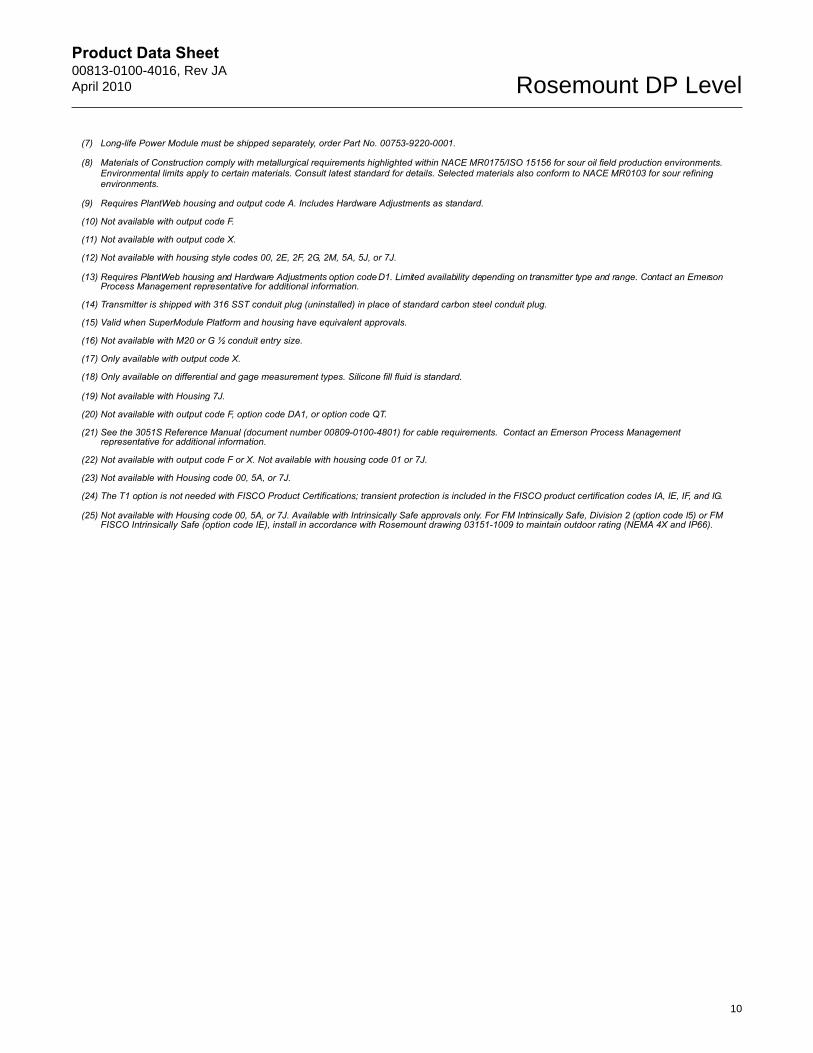
(7) Long-life Power Module must be shipped separately, order Part No. 00753-9220-0001.
(8) Materials of Construction comply with metallurgical requirements highlighted within NACE MR0175/ISO 15156 for sour oil field production environments. Environmental limits apply to certain materials. Consult latest standard for details. Selected materials also conform to NACE MR0103 for sour refining environments.
(9) Requires PlantWeb housing and output code A. Includes Hardware Adjustments as standard.
(10) Not available with output code F.
(11) Not available with output code X.
(12) Not available with housing style codes 00, 2E, 2F, 2G, 2M, 5A, 5J, or 7J.
(13) Requires PlantWeb housing and Hardware Adjustments option code D1. Limited availability depending on transmitter type and range. Contact an Emerson Process Management representative for additional information.
(14) Transmitter is shipped with 316 SST conduit plug (uninstalled) in place of standard carbon steel conduit plug.
(15) Valid when SuperModule Platform and housing have equivalent approvals.
(16) Not available with M20 or G ½ conduit entry size.
(17) Only available with output code X.
(18) Only available on differential and gage measurement types. Silicone fill fluid is standard.
(19) Not available with Housing 7J.
(20) Not available with output code F, option code DA1, or option code QT.
(21) See the 3051S Reference Manual (document number 00809-0100-4801) for cable requirements. Contact an Emerson Process Management representative for additional information.
(22) Not available with output code F or X. Not available with housing code 01 or 7J.
(23) Not available with Housing code 00, 5A, or 7J.
(24) The T1 option is not needed with FISCO Product Certifications; transient protection is included in the FISCO product certification codes IA, IE, IF, and IG.
(25) Not available with Housing code 00, 5A, or 7J. Available with Intrinsically Safe approvals only. For FM Intrinsically Safe, Division 2 (option code I5) or FM FISCO Intrinsically Safe (option code IE), install in accordance with Rosemount drawing 03151-1009 to maintain outdoor rating (NEMA 4X and IP66).
10
Product Data Sheet00813-0100-4016, Rev JA
April 2010Rosemount DP Level
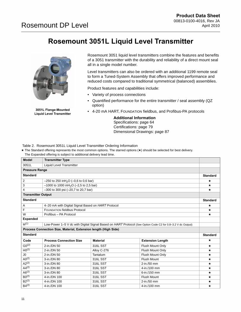
Rosemount 3051L Liquid Level Transmitter
Rosemount 3051 liquid level transmitters combine the features and benefits of a 3051 transmitter with the durability and reliability of a direct mount seal all in a single model number.
Level transmitters can also be ordered with an additional 1199 remote seal to form a Tuned-System Assembly that offers improved performance and reduced costs compared to traditional symmetrical (balanced) assemblies.
Product features and capabilities include:
• Variety of process connections
• Quantified performance for the entire transmitter / seal assembly (QZ option)
• 4-20 mA HART, FOUNDATION fieldbus, and Profibus-PA protocols
Additional InformationSpecifications: page 64Certifications: page 79Dimensional Drawings: page 87
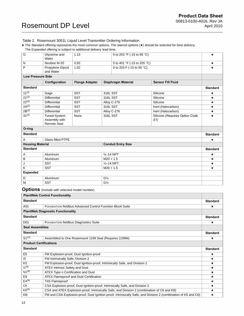
Table 2. Rosemount 3051L Liquid Level Transmitter Ordering Information★ The Standard offering represents the most common options. The starred options (★) should be selected for best delivery.__The Expanded offering is subject to additional delivery lead time.
Model Transmitter Type3051L Liquid Level Transmitter
Pressure RangeStandard Standard2 –250 to 250 inH2O (–0,6 to 0,6 bar) ★
3 –1000 to 1000 inH2O (–2,5 to 2,5 bar) ★
4 –300 to 300 psi (–20,7 to 20,7 bar) ★
Transmitter OutputStandard StandardA 4–20 mA with Digital Signal Based on HART Protocol ★
F FOUNDATION fieldbus Protocol ★
W Profibus – PA Protocol ★
Expanded
M(1) Low-Power 1–5 V dc with Digital Signal Based on HART Protocol (See Option Code C2 for 0.8–3.2 V dc Output)
Process Connection Size, Material, Extension length (High Side)Standard Standard
Code Process Connection Size Material Extension Length ★
G0(2) 2-in./DN 50 316L SST Flush Mount Only ★
H0(2) 2-in./DN 50 Alloy C-276 Flush Mount Only ★
J0 2-in./DN 50 Tantalum Flush Mount Only ★
A0(2) 3-in./DN 80 316L SST Flush Mount ★
A2(2) 3-in./DN 80 316L SST 2-in./50 mm ★
A4(2) 3-in./DN 80 316L SST 4-in./100 mm ★
A6(2) 3-in./DN 80 316L SST 6-in./150 mm ★
B0(2) 4-in./DN 100 316L SST Flush Mount ★
B2(2) 4-in./DN 100 316L SST 2-in./50 mm ★
B4(2) 4-in./DN 100 316L SST 4-in./100 mm ★
3051L Flange-Mounted Liquid Level Transmitter
11
Product Data Sheet00813-0100-4016, Rev JAApril 2010 Rosemount DP Level
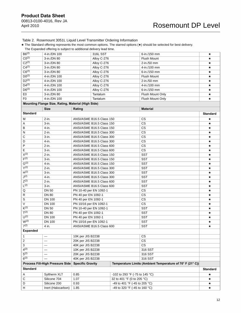
B6(2) 4-in./DN 100 316L SST 6-in./150 mm ★
C0(2) 3-in./DN 80 Alloy C-276 Flush Mount ★
C2(2) 3-in./DN 80 Alloy C-276 2-in./50 mm ★
C4(2) 3-in./DN 80 Alloy C-276 4-in./100 mm ★
C6(2) 3-in./DN 80 Alloy C-276 6-in./150 mm ★
D0(2) 4-in./DN 100 Alloy C-276 Flush Mount ★
D2(2) 4-in./DN 100 Alloy C-276 2-in./50 mm ★
D4(2) 4-in./DN 100 Alloy C-276 4-in./100 mm ★
D6(2) 4-in./DN 100 Alloy C-276 6-in./150 mm ★
E0 3-in./DN 80 Tantalum Flush Mount Only ★
F0 4-in./DN 100 Tantalum Flush Mount Only ★
Mounting Flange Size, Rating, Material (High Side)Size Rating Material
Standard StandardM 2-in. ANSI/ASME B16.5 Class 150 CS ★
A 3-in. ANSI/ASME B16.5 Class 150 CS ★
B 4-in. ANSI/ASME B16.5 Class 150 CS ★
N 2-in. ANSI/ASME B16.5 Class 300 CS ★
C 3-in. ANSI/ASME B16.5 Class 300 CS ★
D 4-in. ANSI/ASME B16.5 Class 300 CS ★
P 2-in. ANSI/ASME B16.5 Class 600 CS ★
E 3-in. ANSI/ASME B16.5 Class 600 CS ★
X(2) 2-in. ANSI/ASME B16.5 Class 150 SST ★
F(2) 3-in. ANSI/ASME B16.5 Class 150 SST ★
G(2) 4-in. ANSI/ASME B16.5 Class 150 SST ★
Y(2) 2-in. ANSI/ASME B16.5 Class 300 SST ★
H(2) 3-in. ANSI/ASME B16.5 Class 300 SST ★
J(2) 4-in. ANSI/ASME B16.5 Class 300 SST ★
Z(2) 2-in. ANSI/ASME B16.5 Class 600 SST ★
L(2) 3-in. ANSI/ASME B16.5 Class 600 SST ★
Q DN 50 PN 10-40 per EN 1092-1 CS ★
R DN 80 PN 40 per EN 1092-1 CS ★
S DN 100 PN 40 per EN 1092-1 CS ★
V DN 100 PN 10/16 per EN 1092-1 CS ★
K(2) DN 50 PN 10-40 per EN 1092-1 SST ★
T(2) DN 80 PN 40 per EN 1092-1 SST ★
U(2) DN 100 PN 40 per EN 1092-1 SST ★
W(2) DN 100 PN 10/16 per EN 1092-1 SST ★
7(2) 4 in. ANSI/ASME B16.5 Class 600 SST ★
Expanded
1 — 10K per JIS B2238 CS
2 — 20K per JIS B2238 CS
3 — 40K per JIS B2238 CS
4(2) — 10K per JIS B2238 316 SST
5(2) — 20K per JIS B2238 316 SST
6(2) — 40K per JIS B2238 316 SST
Process Fill-High Pressure Side Specific Gravity Temperature Limits (Ambient Temperature of 70° F (21° C))Standard StandardA Syltherm XLT 0.85 -102 to 293 °F (-75 to 145 °C) ★
C Silicone 704 1.07 32 to 401 °F (0 to 205 °C) ★
D Silicone 200 0.93 -49 to 401 °F (-45 to 205 °C) ★
H Inert (Halocarbon) 1.85 -49 to 320 °F (-45 to 160 °C) ★
Table 2. Rosemount 3051L Liquid Level Transmitter Ordering Information★ The Standard offering represents the most common options. The starred options (★) should be selected for best delivery.__The Expanded offering is subject to additional delivery lead time.
12
Product Data Sheet00813-0100-4016, Rev JA
April 2010Rosemount DP Level
G Glycerine and Water
1.13 5 to 203 °F (-15 to 95 °C) ★
N Neobee M-20 0.92 5 to 401 °F (-15 to 205 °C) ★
P Propylene Glycol and Water
1.02 5 to 203 F (-15 to 95 °C) ★
Low Pressure Side
Configuration Flange Adapter Diaphragm Material Sensor Fill FluidStandard Standard11(2) Gage SST 316L SST Silicone ★
21(2) Differential SST 316L SST Silicone ★
22(2) Differential SST Alloy C-276 Silicone ★
2A(2) Differential SST 316L SST Inert (Halocarbon) ★
2B(2) Differential SST Alloy C-276 Inert (Halocarbon) ★
31(2) Tuned-System Assembly with Remote Seal
None 316L SST Silicone (Requires Option Code S1)
★
O-ringStandard StandardA Glass-filled PTFE ★
Housing Material Conduit Entry SizeStandard StandardA Aluminum ½–14 NPT ★
B Aluminum M20 × 1.5 ★
J SST ½–14 NPT ★
K SST M20 × 1.5 ★
Expanded
D Aluminum G½
M SST G½
Options (Include with selected model number)
PlantWeb Control FunctionalityStandard StandardA01 FOUNDATION fieldbus Advanced Control Function Block Suite ★
PlantWeb Diagnostic FunctionalityStandard StandardD01 FOUNDATION fieldbus Diagnostics Suite ★
Seal AssembliesStandard StandardS1(3) Assembled to One Rosemount 1199 Seal (Requires 1199M) ★
Product CertificationsStandard StandardE5 FM Explosion-proof, Dust Ignition-proof ★
I5 FM Intrinsically Safe, Division 2 ★
K5 FM Explosion-proof, Dust Ignition-proof, Intrinsically Safe, and Division 2 ★
I1(4) ATEX Intrinsic Safety and Dust ★
N1(4) ATEX Type n Certification and Dust ★
E8 ATEX Flameproof and Dust Certification ★
E4(4) TIIS Flameproof ★
C6 CSA Explosion-proof, Dust Ignition-proof, Intrinsically Safe, and Division 2 ★
K6(4) CSA and ATEX Explosion-proof, Intrinsically Safe, and Division 2 (combination of C6 and K8) ★
KB FM and CSA Explosion-proof, Dust Ignition-proof, Intrinsically Safe, and Division 2 (combination of K5 and C6) ★
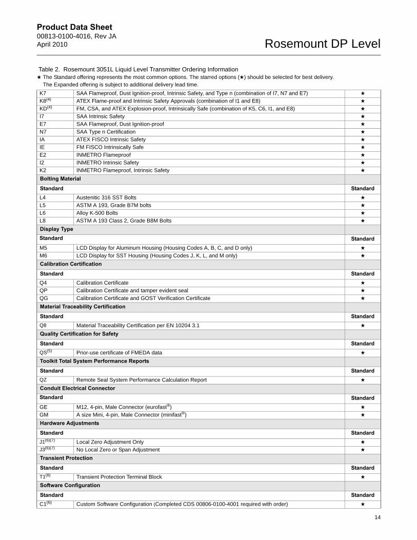
Table 2. Rosemount 3051L Liquid Level Transmitter Ordering Information★ The Standard offering represents the most common options. The starred options (★) should be selected for best delivery.__The Expanded offering is subject to additional delivery lead time.
13
Product Data Sheet00813-0100-4016, Rev JAApril 2010 Rosemount DP Level
K7 SAA Flameproof, Dust Ignition-proof, Intrinsic Safety, and Type n (combination of I7, N7 and E7) ★
K8(4) ATEX Flame-proof and Intrinsic Safety Approvals (combination of I1 and E8) ★
KD(4) FM, CSA, and ATEX Explosion-proof, Intrinsically Safe (combination of K5, C6, I1, and E8) ★
I7 SAA Intrinsic Safety ★
E7 SAA Flameproof, Dust Ignition-proof ★
N7 SAA Type n Certification ★
IA ATEX FISCO Intrinsic Safety ★
IE FM FISCO Intrinsically Safe ★
E2 INMETRO Flameproof ★
I2 INMETRO Intrinsic Safety ★
K2 INMETRO Flameproof, Intrinsic Safety ★
Bolting Material
Standard StandardL4 Austenitic 316 SST Bolts ★
L5 ASTM A 193, Grade B7M bolts ★
L6 Alloy K-500 Bolts ★
L8 ASTM A 193 Class 2, Grade B8M Bolts ★
Display TypeStandard StandardM5 LCD Display for Aluminum Housing (Housing Codes A, B, C, and D only) ★
M6 LCD Display for SST Housing (Housing Codes J, K, L, and M only) ★
Calibration Certification
Standard StandardQ4 Calibration Certificate ★
QP Calibration Certificate and tamper evident seal ★
QG Calibration Certificate and GOST Verification Certificate ★
Material Traceability Certification
Standard StandardQ8 Material Traceability Certification per EN 10204 3.1 ★
Quality Certification for Safety
Standard StandardQS(5) Prior-use certificate of FMEDA data ★
Toolkit Total System Performance Reports
Standard StandardQZ Remote Seal System Performance Calculation Report ★
Conduit Electrical ConnectorStandard StandardGE M12, 4-pin, Male Connector (eurofast®) ★
GM A size Mini, 4-pin, Male Connector (minifast®) ★
Hardware Adjustments
Standard StandardJ1(6)(7) Local Zero Adjustment Only ★
J3(6)(7) No Local Zero or Span Adjustment ★
Transient Protection
Standard StandardT1(8) Transient Protection Terminal Block ★
Software Configuration
Standard StandardC1(6) Custom Software Configuration (Completed CDS 00806-0100-4001 required with order) ★
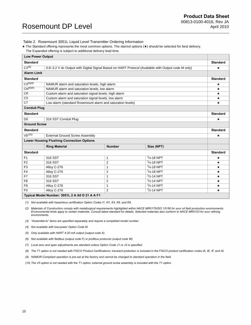
Table 2. Rosemount 3051L Liquid Level Transmitter Ordering Information★ The Standard offering represents the most common options. The starred options (★) should be selected for best delivery.__The Expanded offering is subject to additional delivery lead time.
14
Product Data Sheet00813-0100-4016, Rev JA
April 2010Rosemount DP Level
Low Power Output
Standard StandardC2(6) 0.8–3.2 V dc Output with Digital Signal Based on HART Protocol (Available with Output code M only) ★
Alarm Limit
Standard StandardC4(6)(9) NAMUR alarm and saturation levels, high alarm ★
CN(6)(9) NAMUR alarm and saturation levels, low alarm ★
CR Custom alarm and saturation signal levels, high alarm ★
CS Custom alarm and saturation signal levels, low alarm ★
CT Low alarm (standard Rosemount alarm and saturation levels) ★
Conduit Plug
Standard StandardD0 316 SST Conduit Plug ★
Ground Screw
Standard StandardV5(10) External Ground Screw Assembly ★
Lower Housing Flushing Connection Options
Ring Material Number Size (NPT)
Standard StandardF1 316 SST 1 1/4-18 NPT ★
F2 316 SST 2 1/4-18 NPT ★
F3 Alloy C-276 1 1/4-18 NPT ★
F4 Alloy C-276 2 1/4-18 NPT ★
F7 316 SST 1 1/2-14 NPT ★
F8 316 SST 2 1/2-14 NPT ★
F9 Alloy C-276 1 1/2-14 NPT ★
F0 Alloy C-276 2 1/2-14 NPT ★
Typical Model Number: 3051L 2 A A0 D 21 A A F1
(1) Not available with hazardous certification Option Codes I1, N1, E4, K6, and K8.
(2) Materials of Construction comply with metallurgical requirements highlighted within NACE MR0175/ISO 15156 for sour oil field production environments. Environmental limits apply to certain materials. Consult latest standard for details. Selected materials also conform to NACE MR0103 for sour refining environments.
(3) “Assemble-to” items are specified separately and require a completed model number.
(4) Not available with low-power Option Code M
(5) Only available with HART 4-20 mA output (output code A).
(6) Not available with fieldbus (output code F) or profibus protocols (output code W).
(7) Local zero and span adjustments are standard unless Option Code J1 or J3 is specified.
(8) The T1 option is not needed with FISCO Product Certifications; transient protection is included in the FISCO product certification codes IA, IE, IF, and IG.
(9) NAMUR-Compliant operation is pre-set at the factory and cannot be changed to standard operation in the field.
(10) The V5 option is not needed with the T1 option; external ground screw assembly is included with the T1 option.
Table 2. Rosemount 3051L Liquid Level Transmitter Ordering Information★ The Standard offering represents the most common options. The starred options (★) should be selected for best delivery.__The Expanded offering is subject to additional delivery lead time.
15
Product Data Sheet00813-0100-4016, Rev JAApril 2010 Rosemount DP Level
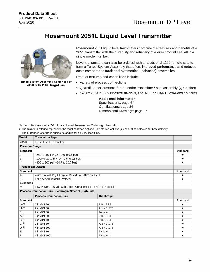
Rosemount 2051L Liquid Level Transmitter
Rosemount 2051 liquid level transmitters combine the features and benefits of a 2051 transmitter with the durability and reliability of a direct mount seal all in a single model number.
Level transmitters can also be ordered with an additional 1199 remote seal to form a Tuned-System Assembly that offers improved performance and reduced costs compared to traditional symmetrical (balanced) assemblies.
Product features and capabilities include:
• Variety of process connections
• Quantified performance for the entire transmitter / seal assembly (QZ option)
• 4-20 mA HART, FOUNDATION fieldbus, and 1-5 Vdc HART Low-Power outputs
Additional InformationSpecifications: page 64Certifications: page 84Dimensional Drawings: page 87
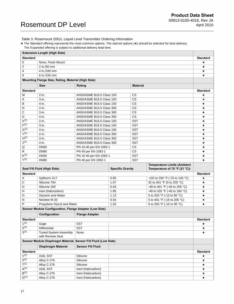
Table 3. Rosemount 2051L Liquid Level Transmitter Ordering Information★ The Standard offering represents the most common options. The starred options (★) should be selected for best delivery.__The Expanded offering is subject to additional delivery lead time.
Model Transmitter Type2051L Liquid Level Transmitter
Pressure RangeStandard Standard2 –250 to 250 inH2O (–0,6 to 0,6 bar) ★
3 –1000 to 1000 inH2O (–2,5 to 2,5 bar) ★
4 –300 to 300 psi (–20,7 to 20,7 bar) ★
Transmitter OutputStandard StandardA 4–20 mA with Digital Signal Based on HART Protocol ★
F FOUNDATION fieldbus Protocol ★
ExpandedM Low-Power, 1–5 Vdc with Digital Signal Based on HART Protocol
Process Connection Size, Diaphragm Material (High Side)
Process Connection Size DiaphragmStandard StandardG(1) 2 in./DN 50 316L SST ★
H(1) 2 in./DN 50 Alloy C-276 ★
J 2 in./DN 50 Tantalum ★
A(1) 3 in./DN 80 316L SST ★
B(1) 4 in./DN 100 316L SST ★
C(1) 3 in./DN 80 Alloy C-276 ★
D(1) 4 in./DN 100 Alloy C-276 ★
E 3 in./DN 80 Tantalum ★
F 4 in./DN 100 Tantalum ★
Tuned-System Assembly Comprised of 2051L with 1199 Flanged Seal
16
Product Data Sheet00813-0100-4016, Rev JA
April 2010Rosemount DP Level
Extension Length (High Side)Standard Standard0 None, Flush Mount ★
2 2 in./50 mm ★
4 4 in./100 mm ★
6 6 in./150 mm ★
Mounting Flange Size, Rating, Material (High Side)
Size Rating MaterialStandard StandardM 2-in. ANSI/ASME B16.5 Class 150 CS ★
A 3-in. ANSI/ASME B16.5 Class 150 CS ★
B 4-in. ANSI/ASME B16.5 Class 150 CS ★
N 2-in. ANSI/ASME B16.5 Class 300 CS ★
C 3-in. ANSI/ASME B16.5 Class 300 CS ★
D 4-in. ANSI/ASME B16.5 Class 300 CS ★
X(1) 2-in. ANSI/ASME B16.5 Class 150 SST ★
F(1) 3-in. ANSI/ASME B16.5 Class 150 SST ★
G(1) 4-in. ANSI/ASME B16.5 Class 150 SST ★
Y(1) 2-in. ANSI/ASME B16.5 Class 300 SST ★
H(1) 3-in. ANSI/ASME B16.5 Class 300 SST ★
J(1) 4-in. ANSI/ASME B16.5 Class 300 SST ★
Q DN50 PN 10-40 per EN 1092-1 CS ★
R DN80 PN 40 per EN 1092-1 CS ★
K(1) DN50 PN 10-40 per EN 1092-1 SST ★
T(1) DN80 PN 40 per EN 1092-1 SST ★
Seal Fill Fluid (High Side) Specific GravityTemperature Limits (Ambient Temperature of 70 °F (21 °C))
Standard StandardA Syltherm XLT 0.85 -102 to 293 °F (-75 to 145 °C) ★
C Silicone 704 1.07 32 to 401 °F (0 to 205 °C) ★
D Silicone 200 0.93 -49 to 401 °F (-45 to 205 °C) ★
H Inert (Halocarbon) 1.85 -49 to 320 °F (-45 to 160 °C) ★
G Glycerin and Water 1.13 5 to 203 °F (-15 to 95 °C) ★
N Neobee M-20 0.92 5 to 401 °F (-15 to 205 °C) ★
P Propylene Glycol and Water 1.02 5 to 203 °F (-15 to 95 °C) ★
Sensor Module Configuration, Flange Adapter (Low Side)
Configuration Flange AdapterStandard Standard1(1) Gage SST ★
2(1) Differential SST ★
3(1) Tuned-System Assembly with Remote Seal
None ★
Sensor Module Diaphragm Material, Sensor Fill Fluid (Low Side)
Diaphragm Material Sensor Fill FluidStandard Standard1(1) 316L SST Silicone ★
2(1) Alloy C-276 Silicone ★
7(1) Alloy C-276 Silicone ★
A(1) 316L SST Inert (Halocarbon) ★
B(1) Alloy C-276 Inert (Halocarbon) ★
G(1) Alloy C-276 Inert (Halocarbon) ★
Table 3. Rosemount 2051L Liquid Level Transmitter Ordering Information★ The Standard offering represents the most common options. The starred options (★) should be selected for best delivery.__The Expanded offering is subject to additional delivery lead time.
17
Product Data Sheet00813-0100-4016, Rev JAApril 2010 Rosemount DP Level
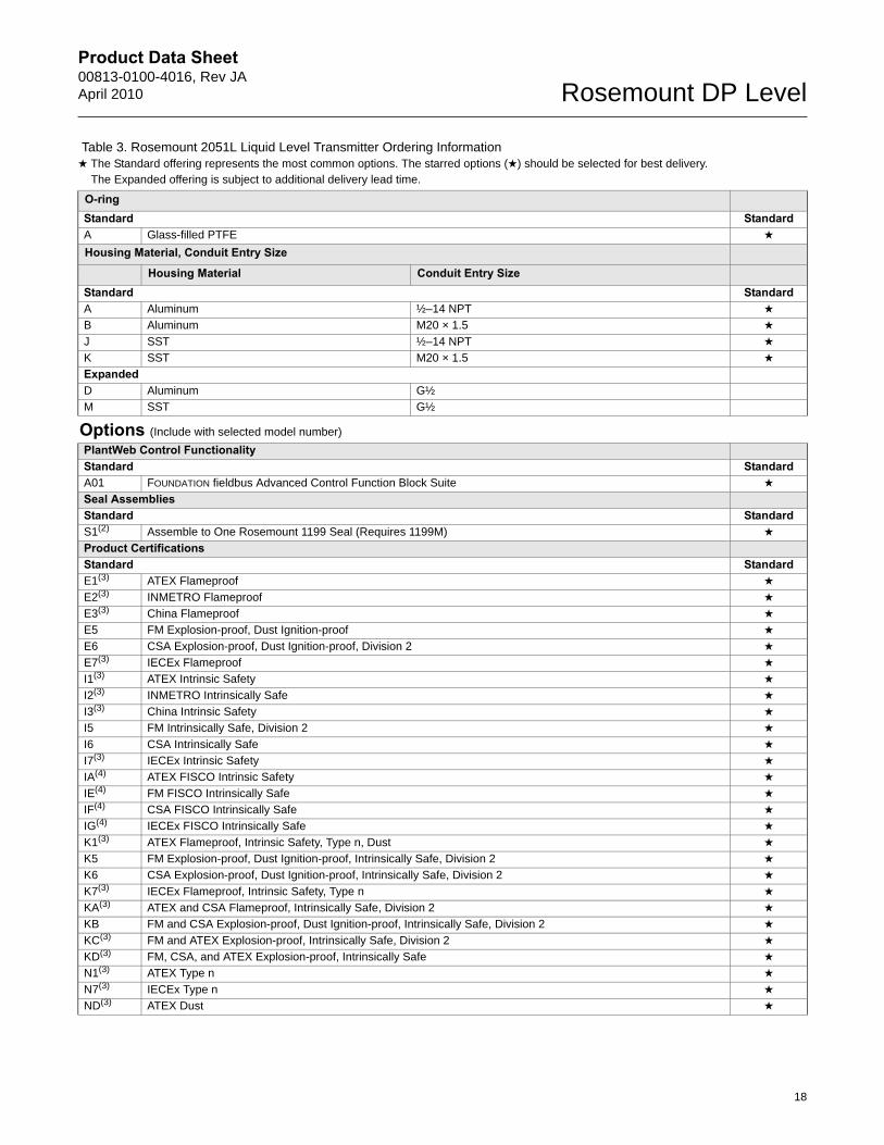
O-ringStandard StandardA Glass-filled PTFE ★
Housing Material, Conduit Entry Size
Housing Material Conduit Entry SizeStandard StandardA Aluminum ½–14 NPT ★
B Aluminum M20 × 1.5 ★
J SST ½–14 NPT ★
K SST M20 × 1.5 ★
ExpandedD Aluminum G½
M SST G½
Options (Include with selected model number)
PlantWeb Control FunctionalityStandard StandardA01 FOUNDATION fieldbus Advanced Control Function Block Suite ★
Seal AssembliesStandard StandardS1(2) Assemble to One Rosemount 1199 Seal (Requires 1199M) ★
Product CertificationsStandard StandardE1(3) ATEX Flameproof ★
E2(3) INMETRO Flameproof ★
E3(3) China Flameproof ★
E5 FM Explosion-proof, Dust Ignition-proof ★
E6 CSA Explosion-proof, Dust Ignition-proof, Division 2 ★
E7(3) IECEx Flameproof ★
I1(3) ATEX Intrinsic Safety ★
I2(3) INMETRO Intrinsically Safe ★
I3(3) China Intrinsic Safety ★
I5 FM Intrinsically Safe, Division 2 ★
I6 CSA Intrinsically Safe ★
I7(3) IECEx Intrinsic Safety ★
IA(4) ATEX FISCO Intrinsic Safety ★
IE(4) FM FISCO Intrinsically Safe ★
IF(4) CSA FISCO Intrinsically Safe ★
IG(4) IECEx FISCO Intrinsically Safe ★
K1(3) ATEX Flameproof, Intrinsic Safety, Type n, Dust ★
K5 FM Explosion-proof, Dust Ignition-proof, Intrinsically Safe, Division 2 ★
K6 CSA Explosion-proof, Dust Ignition-proof, Intrinsically Safe, Division 2 ★
K7(3) IECEx Flameproof, Intrinsic Safety, Type n ★
KA(3) ATEX and CSA Flameproof, Intrinsically Safe, Division 2 ★
KB FM and CSA Explosion-proof, Dust Ignition-proof, Intrinsically Safe, Division 2 ★
KC(3) FM and ATEX Explosion-proof, Intrinsically Safe, Division 2 ★
KD(3) FM, CSA, and ATEX Explosion-proof, Intrinsically Safe ★
N1(3) ATEX Type n ★
N7(3) IECEx Type n ★
ND(3) ATEX Dust ★
Table 3. Rosemount 2051L Liquid Level Transmitter Ordering Information★ The Standard offering represents the most common options. The starred options (★) should be selected for best delivery.__The Expanded offering is subject to additional delivery lead time.
18
Product Data Sheet00813-0100-4016, Rev JA
April 2010Rosemount DP Level
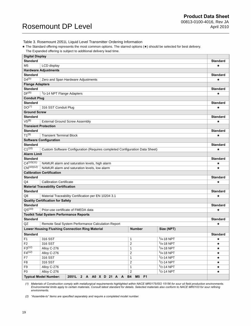
Digital DisplayStandard StandardM5 LCD display ★
Hardware AdjustmentsStandard StandardD4(5) Zero and Span Hardware Adjustments ★
Flange AdaptersStandard StandardDF(6) 1/2-14 NPT Flange Adapters ★
Conduit PlugStandard StandardDO(7) 316 SST Conduit Plug ★
Ground ScrewStandard StandardV5(8) External Ground Screw Assembly ★
Transient ProtectionStandard StandardT1(9) Transient Terminal Block ★
Software ConfigurationStandard StandardC1(10) Custom Software Configuration (Requires completed Configuration Data Sheet) ★
Alarm LimitStandard StandardC4(10)(11) NAMUR alarm and saturation levels, high alarm ★
CN(10)(12) NAMUR alarm and saturation levels, low alarm ★
Calibration CertificationStandard StandardQ4 Calibration Certificate ★
Material Traceability CertificationStandard StandardQ8 Material Traceability Certification per EN 10204 3.1 ★
Quality Certification for SafetyStandard StandardQS(10) Prior-use certificate of FMEDA data ★
Toolkit Total System Performance ReportsStandard StandardQZ Remote Seal System Performance Calculation Report ★
Lower Housing Flushing Connection Ring Material Number Size (NPT)Standard StandardF1 316 SST 1 1/4-18 NPT ★
F2 316 SST 2 1/4-18 NPT ★
F3(12) Alloy C-276 1 1/4-18 NPT ★
F4(12) Alloy C-276 2 1/4-18 NPT ★
F7 316 SST 1 1/2-14 NPT ★
F8 316 SST 2 1/2-14 NPT ★
F9 Alloy C-276 1 1/2-14 NPT ★
F0 Alloy C-276 2 1/2-14 NPT ★
Typical Model Number: 2051L 2 A A0 X D 21 A A B4 M5 F1
(1) Materials of Construction comply with metallurgical requirements highlighted within NACE MR0175/ISO 15156 for sour oil field production environments. Environmental limits apply to certain materials. Consult latest standard for details. Selected materials also conform to NACE MR0103 for sour refining environments.
(2) “Assemble-to” items are specified separately and require a completed model number.
Table 3. Rosemount 2051L Liquid Level Transmitter Ordering Information★ The Standard offering represents the most common options. The starred options (★) should be selected for best delivery.__The Expanded offering is subject to additional delivery lead time.
19

Product Data Sheet00813-0100-4016, Rev JAApril 2010 Rosemount DP Level
(3) Not available with Low Power output code M.
(4) Only valid with FOUNDATION fieldbus output code F.
(5) Not valid with FOUNDATION fieldbus output code F.
(6) Not available with Remote Mount Seal Assembly option S1.
(7) Transmitter is shipped with 316 SST conduit plug (uninstalled) in place of standard carbon steel conduit plug
(8) The V5 option is not needed with the T1 option; external ground screw assembly is included with the T1 option.
(9) The T1 option is not needed with FISCO Product Certifications; transient protection is included in the FISCO product certification codes IA, IE, IF, and IG.
(10) Only available with HART 4-20 mA output (output code A).
(11) NAMUR-Compliant operation is pre-set at the factory and cannot be changed to standard operation in the field.
(12) Not available with Option Codes A0, B0, and G0.
20
Product Data Sheet00813-0100-4016, Rev JA
April 2010Rosemount DP Level
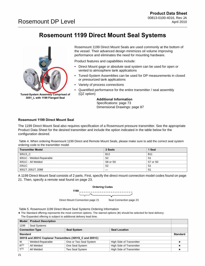
Rosemount 1199 Direct Mount Seal Systems
Rosemount 1199 Direct Mount Seals are used commonly at the bottom of the vessel. Their advanced design minimizes oil volume improving performance and eliminates the need for mounting hardware.
Product features and capabilities include:
• Direct Mount gage or absolute seal system can be used for open or vented to atmosphere tank applications
• Tuned-System Assemblies can be used for DP measurements in closed or pressurized tank applications
• Variety of process connections
• Quantified performance for the entire transmitter / seal assembly (QZ option)
Additional InformationSpecifications: page 73Dimensional Drawings: page 87
Rosemount 1199 Direct Mount Seal
The 1199 Direct Mount Seal also requires specification of a Rosemount pressure transmitter. See the appropriate Product Data Sheet for the desired transmitter and include the option indicated in the table below for the configuration desired.
A 1199 Direct Mount Seal consists of 2 parts. First, specify the direct mount connection model codes found on page 21. Then, specify a remote seal found on page 23.
Table 4. When ordering Rosemount 1199 Direct and Remote Mount Seals, please make sure to add the correct seal system ordering code to the transmitter model
Transmitter Model 2 Seals 1 Seal3051S_C B12 B11
3051C - Welded-Repairable S2 S1
3051C - All Welded S8 or S9 S7 or S0
2051C S2 S1
3051T, 2051T, 2088 — S1
Ordering Codes1199 _ _ _ _ _ _ _ _ _ _ _ _ _ _ _ _ _ _ _ _ _ _ _ _
Tuned-System Assembly Comprised of 3051_L with 1199 Flanged Seal
Direct Mount Connection page 21 Seal Connection page 23
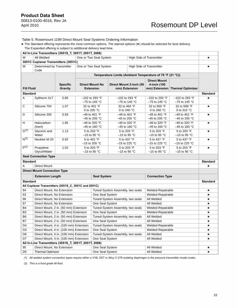
Table 5. Rosemount 1199 Direct Mount Seal Systems Ordering Information★ The Standard offering represents the most common options. The starred options (★) should be selected for best delivery.__The Expanded offering is subject to additional delivery lead time.
Model Product Description1199 Seal Systems
Connection Type Seal System Seal LocationStandard Standard3051S and 2051C Coplanar Transmitters (3051S_C and 2051C)W Welded-Repairable One or Two Seal System High Side of Transmitter ★
R(1) All Welded One Seal System High Side of Transmitter ★
T(1) All Welded Two Seal System High Side of Transmitter ★
21
Product Data Sheet00813-0100-4016, Rev JAApril 2010 Rosemount DP Level
22
All In-Line Transmitters (3051S_T, 3051T, 2051T, 2088)W All Welded One or Two Seal System High Side of Transmitter ★
3051C Coplanar Transmitters (3051C)W Determined by Transmitter
CodeOne or Two Seal System High Side of Transmitter ★
Fill FluidSpecific Gravity
Temperature Limits (Ambient Temperature of 70 °F (21 °C))
Direct Mount No Extension
Direct Mount 2-inch (50 mm) Extension
Direct Mount 4-inch (100
mm) Extension Thermal OptimizerStandard StandardA Syltherm XLT 0.85 –102 to 293 °F
–75 to 145 °C –102 to 293 °F –75 to 145 °C
–102 to 293 °F –75 to 145 °C
–102 to 293 °F –75 to 145 °C
★
C Silicone 704 1.07 32 to 401 °F0 to 205 °C
32 to 464 °F0 to 240 °C
32 to 500 °F 0 to 260 °C
32 to 599 °F 0 to 315 °C
★
D Silicone 200 0.93 –49 to 401 °F –45 to 205 °C
–49 to 401 °F–45 to 205 °C
–49 to 401 °F –45 to 205 °C
–49 to 401 °F –45 to 205 °C
★
H Halocarbon (Inert)
1.85 –49 to 320 °F –45 to 160 °C
–49 to 320 °F –45 to 160 °C
–49 to 320 °F –45 to 160 °C
–49 to 320 °F –45 to 160 °C
★
G(2) Glycerin and Water
1.13 5 to 203 °F–15 to 95 °C
5 to 203 °F–15 to 95 °C
5 to 203 °F–15 to 95 °C
5 to 203 °F–15 to 95 °C
★
N(2) Neobee M-20 0.92 5 to 401 °F–15 to 205 °C
5 to 437 °F–15 to 225 °C
5 to 437 °F–15 to 225 °C
5 to 437 °F–15 to 225 °C
★
P(2) Propylene Glycol/Water
1.02 5 to 203 °F–15 to 95 °C
5 to 203 °F–15 to 95 °C
5 to 203 °F–15 to 95 °C
5 to 203 °F–15 to 95 °C
★
Seal Connection Type Standard StandardA Direct Mount ★
Direct Mount Connection Type
Extension Length Seal System Connection TypeStandard StandardAll Coplanar Transmitters (3051S_C, 3051C and 2051C)94 Direct Mount, No Extension Tuned-System Assembly, two seals Welded-Repairable ★
93 Direct Mount, No Extension One Seal System Welded-Repairable ★
96 Direct Mount, No Extension Tuned-System Assembly, two seals All Welded ★
97 Direct Mount, No Extension One Seal System All Welded ★
B4 Direct Mount, 2 in. (50 mm) Extension Tuned-System Assembly, two seals Welded-Repairable ★
B3 Direct Mount, 2 in. (50 mm) Extension One Seal System Welded-Repairable ★
B6 Direct Mount, 2 in. (50 mm) Extension Tuned-System Assembly, two seals All Welded ★
B7 Direct Mount, 2 in. (50 mm) Extension One Seal System All Welded ★
D4 Direct Mount, 4 in. (100 mm) Extension Tuned-System Assembly, two seals Welded-Repairable ★
D3 Direct Mount, 4 in. (100 mm) Extension One Seal System Welded-Repairable ★
D6 Direct Mount, 4 in. (100 mm) Extension Tuned-System Assembly, two seals All Welded ★
D7 Direct Mount, 4 in. (100 mm) Extension One Seal System All Welded ★
All In-Line Transmitters (3051S_T, 3051T, 2051T, 2088)95 Direct Mount, No Extension One Seal System All Welded ★
D5 Thermal Optimizer One Seal System All Welded ★
(1) All welded system connection types require either a 316L SST or Alloy C-276 isolating diaphragm in the pressure transmitter model codes.
(2) This is a food grade fill fluid.
Table 5. Rosemount 1199 Direct Mount Seal Systems Ordering Information★ The Standard offering represents the most common options. The starred options (★) should be selected for best delivery.__The Expanded offering is subject to additional delivery lead time.
Product Data Sheet00813-0100-4016, Rev JA
April 2010Rosemount DP Level
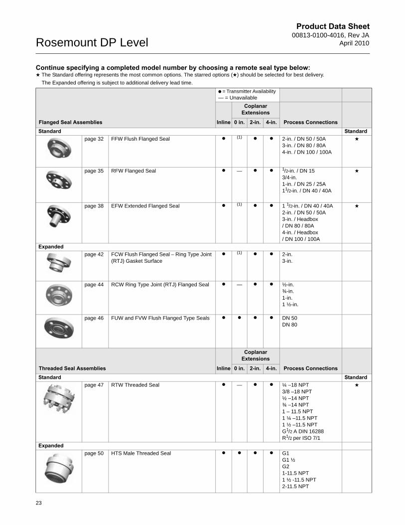
Continue specifying a completed model number by choosing a remote seal type below:★ The Standard offering represents the most common options. The starred options (★) should be selected for best delivery.
__The Expanded offering is subject to additional delivery lead time.
Flanged Seal Assemblies
● = Transmitter Availability — = Unavailable
Inline
Coplanar Extensions
Process Connections0 in. 2-in. 4-in.Standard Standard
page 32 FFW Flush Flanged Seal ● (1) ● ● 2-in. / DN 50 / 50A3-in. / DN 80 / 80A4-in. / DN 100 / 100A
★
page 35 RFW Flanged Seal ● — ● ● 1/2-in. / DN 153/4-in.1-in. / DN 25 / 25A11/2-in. / DN 40 / 40A
★
page 38 EFW Extended Flanged Seal ● (1) ● ● 1 1/2-in. / DN 40 / 40A2-in. / DN 50 / 50A3-in. / Headbox/ DN 80 / 80A4-in. / Headbox/ DN 100 / 100A
★
Expandedpage 42 FCW Flush Flanged Seal – Ring Type Joint
(RTJ) Gasket Surface
● (1) ● ● 2-in.3-in.
page 44 RCW Ring Type Joint (RTJ) Flanged Seal ● — ● ● ½-in.¾-in.1-in.1 ½-in.
page 46 FUW and FVW Flush Flanged Type Seals ● ● ● ● DN 50DN 80
Threaded Seal Assemblies Inline
Coplanar Extensions
Process Connections0 in. 2-in. 4-in.Standard Standard
page 47 RTW Threaded Seal ● — ● ● ¼ –18 NPT3/8 –18 NPT½ –14 NPT¾ –14 NPT1 – 11.5 NPT1 ¼ –11.5 NPT1 ½ –11.5 NPTG1/2 A DIN 16288R1/2 per ISO 7/1
★
Expandedpage 50 HTS Male Threaded Seal ● ● ● ● G1
G1 ½ G21-11.5 NPT1 ½ -11.5 NPT2-11.5 NPT
23
Product Data Sheet00813-0100-4016, Rev JAApril 2010 Rosemount DP Level
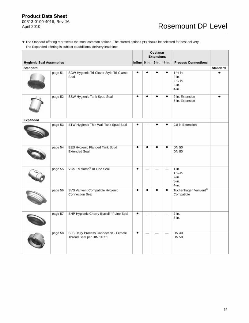
Hygienic Seal Assemblies Inline
Coplanar Extensions
Process Connections0 in. 2-in. 4-in.Standard Standard
page 51 SCW Hygienic Tri-Clover Style Tri-Clamp Seal
● ● ● ● 1 ½-in.2-in.2 ½-in.3-in.4-in.
★
page 52 SSW Hygienic Tank Spud Seal ● ● ● ● 2-in. Extension6-in. Extension
★
Expandedpage 53 STW Hygienic Thin Wall Tank Spud Seal ● — ● ● 0.8 in Extension
page 54 EES Hygienic Flanged Tank Spud Extended Seal
● ● ● ● DN 50DN 80
page 55 VCS Tri-clamp® In-Line Seal ● — — — 1-in.1 ½-in.2-in.3-in.4-in.
page 56 SVS Varivent Compatible Hygienic Connection Seal
● ● ● ● Tuchenhagen Varivent® Compatible
page 57 SHP Hygienic Cherry-Burrell “I” Line Seal ● — — — 2-in.3-in.
page 58 SLS Dairy Process Connection - Female Thread Seal per DIN 11851
● — — — DN 40DN 50
★ The Standard offering represents the most common options. The starred options (★) should be selected for best delivery.
__The Expanded offering is subject to additional delivery lead time.
24
Product Data Sheet00813-0100-4016, Rev JA
April 2010Rosemount DP Level
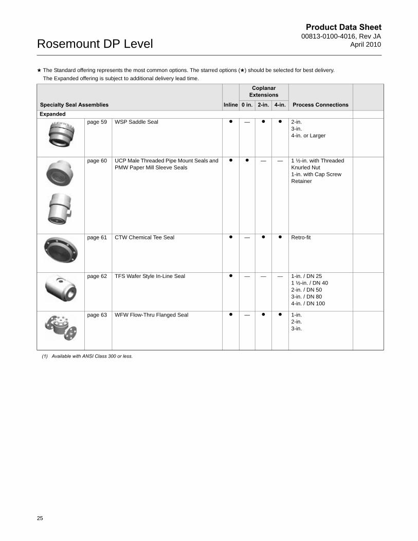
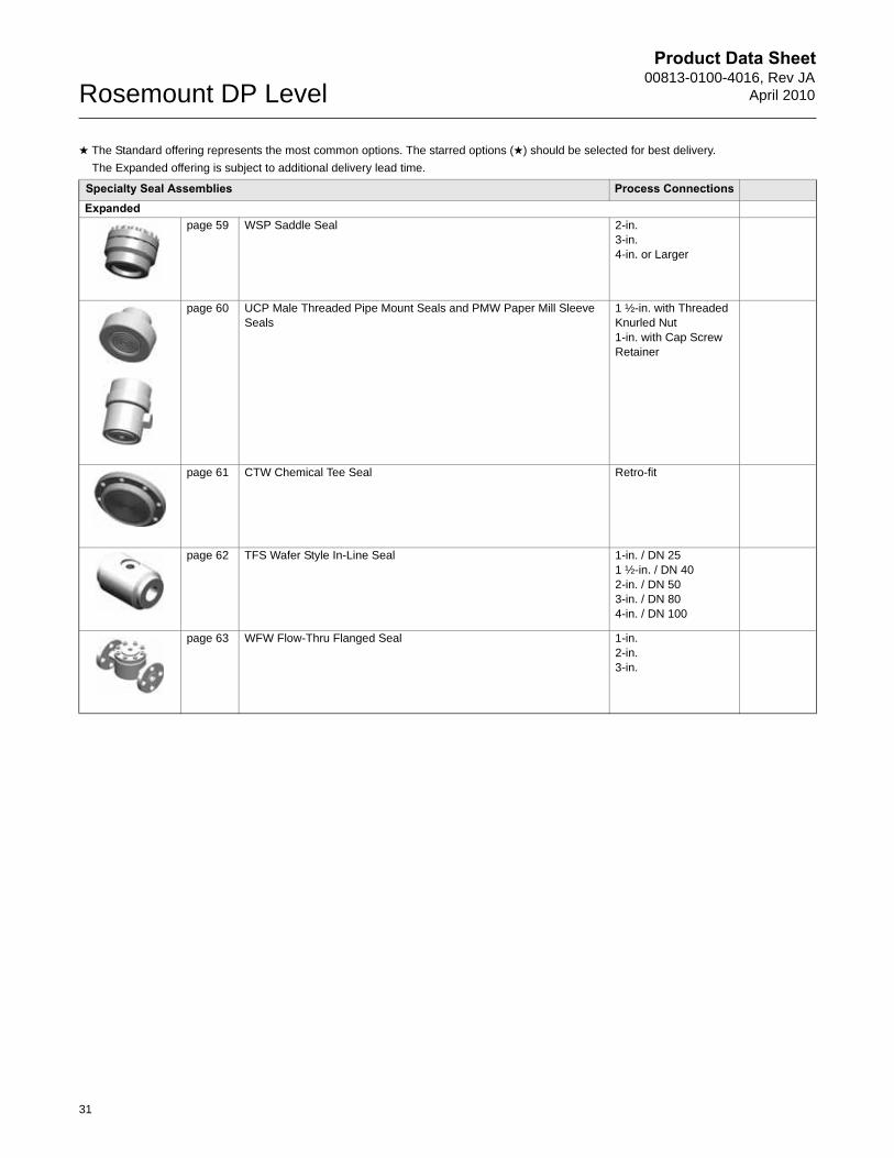
Specialty Seal Assemblies Inline
Coplanar Extensions
Process Connections0 in. 2-in. 4-in.Expanded
page 59 WSP Saddle Seal ● — ● ● 2-in.3-in.4-in. or Larger
page 60 UCP Male Threaded Pipe Mount Seals and PMW Paper Mill Sleeve Seals
● ● — — 1 ½-in. with Threaded Knurled Nut1-in. with Cap Screw Retainer
page 61 CTW Chemical Tee Seal ● — ● ● Retro-fit
page 62 TFS Wafer Style In-Line Seal ● — — — 1-in. / DN 251 ½-in. / DN 402-in. / DN 503-in. / DN 804-in. / DN 100
page 63 WFW Flow-Thru Flanged Seal ● — ● ● 1-in.2-in.3-in.
(1) Available with ANSI Class 300 or less.
★ The Standard offering represents the most common options. The starred options (★) should be selected for best delivery.
__The Expanded offering is subject to additional delivery lead time.
25
Product Data Sheet00813-0100-4016, Rev JAApril 2010 Rosemount DP Level
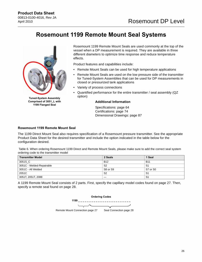
Rosemount 1199 Remote Mount Seal Systems
Rosemount 1199 Remote Mount Seals are used commonly at the top of the vessel when a DP measurement is required. They are available in three different diameters to optimize time response and reduce temperature effects.
Product features and capabilities include:
• Remote Mount Seals can be used for high temperature applications
• Remote Mount Seals are used on the low pressure side of the transmitter for Tuned-System Assemblies that can be used for DP measurements in closed or pressurized tank applications
• Variety of process connections
• Quantified performance for the entire transmitter / seal assembly (QZ option)
Additional InformationSpecifications: page 64Certifications: page 74Dimensional Drawings: page 87
Rosemount 1199 Remote Mount Seal
The 1199 Direct Mount Seal also requires specification of a Rosemount pressure transmitter. See the appropriate Product Data Sheet for the desired transmitter and include the option indicated in the table below for the configuration desired.
A 1199 Remote Mount Seal consists of 2 parts. First, specify the capillary model codes found on page 27. Then, specify a remote seal found on page 28.
Table 6. When ordering Rosemount 1199 Direct and Remote Mount Seals, please make sure to add the correct seal system ordering code to the transmitter model
Transmitter Model 2 Seals 1 Seal3051S_C B12 B11
3051C - Welded-Repairable S2 S1
3051C - All Welded S8 or S9 S7 or S0
2051C S2 S1
3051T, 2051T, 2088 — S1
Ordering Codes1199 _ _ _ _ _ _ _ _ _ _ _ _ _ _ _ _ _ _ _ _ _ _ _ _
Remote Mount Connection page 27 Seal Connection page 28
Tuned-System Assembly Comprised of 3051_L with
1199 Flanged Seal
26
Product Data Sheet00813-0100-4016, Rev JA
April 2010Rosemount DP Level
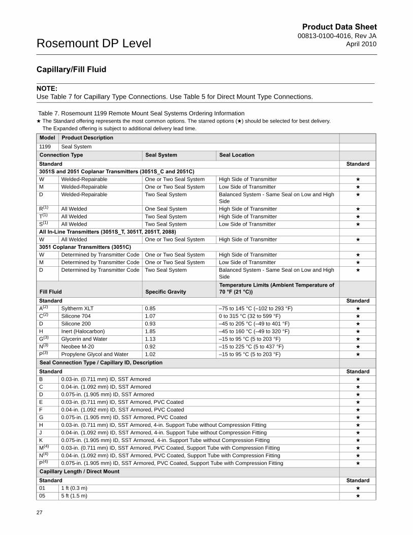
Capillary/Fill Fluid
NOTE: Use Table 7 for Capillary Type Connections. Use Table 5 for Direct Mount Type Connections.
Table 7. Rosemount 1199 Remote Mount Seal Systems Ordering Information★ The Standard offering represents the most common options. The starred options (★) should be selected for best delivery.__The Expanded offering is subject to additional delivery lead time.
Model Product Description1199 Seal System
Connection Type Seal System Seal LocationStandard Standard3051S and 2051 Coplanar Transmitters (3051S_C and 2051C)W Welded-Repairable One or Two Seal System High Side of Transmitter ★
M Welded-Repairable One or Two Seal System Low Side of Transmitter ★
D Welded-Repairable Two Seal System Balanced System - Same Seal on Low and High Side
★
R(1) All Welded One Seal System High Side of Transmitter ★
T(1) All Welded Two Seal System High Side of Transmitter ★
S(1) All Welded Two Seal System Low Side of Transmitter ★
All In-Line Transmitters (3051S_T, 3051T, 2051T, 2088)W All Welded One or Two Seal System High Side of Transmitter ★
3051 Coplanar Transmitters (3051C)W Determined by Transmitter Code One or Two Seal System High Side of Transmitter ★
M Determined by Transmitter Code One or Two Seal System Low Side of Transmitter ★
D Determined by Transmitter Code Two Seal System Balanced System - Same Seal on Low and High Side
★
Fill Fluid Specific GravityTemperature Limits (Ambient Temperature of 70 °F (21 °C))
Standard StandardA(2) Syltherm XLT 0.85 –75 to 145 °C (–102 to 293 °F) ★
C(2) Silicone 704 1.07 0 to 315 °C (32 to 599 °F) ★
D Silicone 200 0.93 –45 to 205 °C (–49 to 401 °F) ★
H Inert (Halocarbon) 1.85 –45 to 160 °C (–49 to 320 °F) ★
G(3) Glycerin and Water 1.13 –15 to 95 °C (5 to 203 °F) ★
N(3) Neobee M-20 0.92 –15 to 225 °C (5 to 437 °F) ★
P(3) Propylene Glycol and Water 1.02 –15 to 95 °C (5 to 203 °F) ★
Seal Connection Type / Capillary ID, DescriptionStandard StandardB 0.03-in. (0.711 mm) ID, SST Armored ★
C 0.04-in. (1.092 mm) ID, SST Armored ★
D 0.075-in. (1.905 mm) ID, SST Armored ★
E 0.03-in. (0.711 mm) ID, SST Armored, PVC Coated ★
F 0.04-in. (1.092 mm) ID, SST Armored, PVC Coated ★
G 0.075-in. (1.905 mm) ID, SST Armored, PVC Coated ★
H 0.03-in. (0.711 mm) ID, SST Armored, 4-in. Support Tube without Compression Fitting ★
J 0.04-in. (1.092 mm) ID, SST Armored, 4-in. Support Tube without Compression Fitting ★
K 0.075-in. (1.905 mm) ID, SST Armored, 4-in. Support Tube without Compression Fitting ★
M(4) 0.03-in. (0.711 mm) ID, SST Armored, PVC Coated, Support Tube with Compression Fitting ★
N(4) 0.04-in. (1.092 mm) ID, SST Armored, PVC Coated, Support Tube with Compression Fitting ★
P(4) 0.075-in. (1.905 mm) ID, SST Armored, PVC Coated, Support Tube with Compression Fitting ★
Capillary Length / Direct MountStandard Standard01 1 ft (0.3 m) ★
05 5 ft (1.5 m) ★
27
Product Data Sheet00813-0100-4016, Rev JAApril 2010 Rosemount DP Level
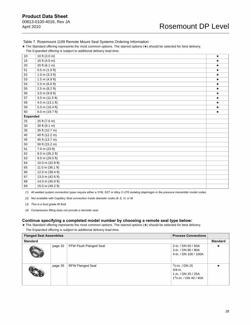
Continue specifying a completed model number by choosing a remote seal type below:
10 10 ft (3.0 m) ★
15 15 ft (4.5 m) ★
20 20 ft (6.1 m) ★
51 0.5 m (1.6 ft) ★
52 1.0 m (3.3 ft) ★
53 1.5 m (4.9 ft) ★
54 2.0 m (6.6 ft) ★
55 2.5 m (8.2 ft) ★
56 3.0 m (9.8 ft) ★
57 3.5 m (11.5 ft) ★
58 4.0 m (13.1 ft) ★
59 5.0 m (16.4 ft) ★
60 6.0 m (19.7 ft) ★
Expanded25 25 ft (7.6 m)
30 30 ft (9.1 m)
35 35 ft (10.7 m)
40 40 ft (12.2 m)
45 45 ft (13.7 m)
50 50 ft (15.2 m)
61 7.0 m (23 ft)
62 8.0 m (26.2 ft)
63 9.0 m (29.5 ft)
64 10.0 m (32.8 ft)
65 11.0 m (36.1 ft)
66 12.0 m (39.4 ft)
67 13.0 m (42.6 ft)
68 14.0 m (45.9 ft)
69 15.0 m (49.2 ft)
(1) All welded system connection types require either a 316L SST or Alloy C-276 isolating diaphragm in the pressure transmitter model codes.
(2) Not available with Capillary Seal connection inside diameter codes B, E, H, or M.
(3) This is a food grade fill fluid.
(4) Compression fitting does not provide a hermetic seal.
★ The Standard offering represents the most common options. The starred options (★) should be selected for best delivery.
__The Expanded offering is subject to additional delivery lead time.
Flanged Seal Assemblies Process ConnectionsStandard Standard
page 32 FFW Flush Flanged Seal 2-in. / DN 50 / 50A3-in. / DN 80 / 80A4-in. / DN 100 / 100A
★
page 35 RFW Flanged Seal 1/2-in. / DN 153/4-in.1-in. / DN 25 / 25A11/2-in. / DN 40 / 40A
★
Table 7. Rosemount 1199 Remote Mount Seal Systems Ordering Information★ The Standard offering represents the most common options. The starred options (★) should be selected for best delivery.__The Expanded offering is subject to additional delivery lead time.
28

Product Data Sheet00813-0100-4016, Rev JA
April 2010Rosemount DP Level
page 38 EFW Extended Flanged Seal 1 1/2-in. / DN 40 / 40A2-in. / DN 50 / 50A3-in. / Headbox/ DN 80 / 80A4-in. / Headbox/ DN 100 / 100A
★
page 40 PFW Pancake Seal 2-in. / DN503-in. / DN 80
★
Expandedpage 42 FCW Flush Flanged Seal – Ring Type Joint (RTJ) Gasket Surface 2-in.
3-in.
page 44 RCW Ring Type Joint (RTJ) Flanged Seal ½-in.¾-in.1-in.1 ½-in.
page 46 FUW and FVW Flush Flanged Type Seals DN 50DN 80
Threaded Seal Assemblies Process ConnectionsStandard Standard
page 47 RTW Threaded Seal ¼ –18 NPT3/8 –18 NPT½ –14 NPT¾ –14 NPT1 – 11.5 NPT1 ¼ –11.5 NPT1 ½ –11.5 NPTG1/2 A DIN 16288R1/2 per ISO 7/1
★
Expandedpage 50 HTS Male Threaded Seal G1
G1 ½ G21-11.5 NPT1 ½ -11.5 NPT2-11.5 NPT
★ The Standard offering represents the most common options. The starred options (★) should be selected for best delivery.
__The Expanded offering is subject to additional delivery lead time.
29
Product Data Sheet00813-0100-4016, Rev JAApril 2010 Rosemount DP Level
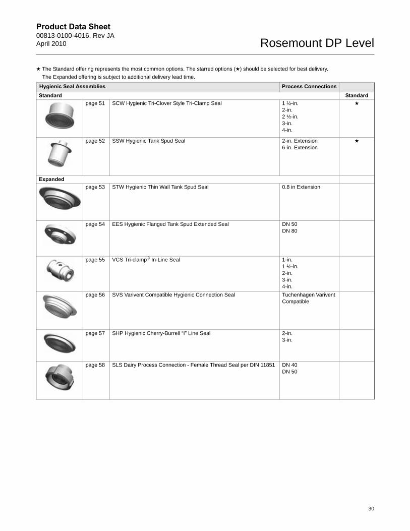
Hygienic Seal Assemblies Process ConnectionsStandard Standard
page 51 SCW Hygienic Tri-Clover Style Tri-Clamp Seal 1 ½-in.2-in.2 ½-in.3-in.4-in.
★
page 52 SSW Hygienic Tank Spud Seal 2-in. Extension6-in. Extension
★
Expandedpage 53 STW Hygienic Thin Wall Tank Spud Seal 0.8 in Extension
page 54 EES Hygienic Flanged Tank Spud Extended Seal DN 50DN 80
page 55 VCS Tri-clamp® In-Line Seal 1-in.1 ½-in.2-in.3-in.4-in.
page 56 SVS Varivent Compatible Hygienic Connection Seal Tuchenhagen Varivent Compatible
page 57 SHP Hygienic Cherry-Burrell “I” Line Seal 2-in.3-in.
page 58 SLS Dairy Process Connection - Female Thread Seal per DIN 11851 DN 40DN 50
★ The Standard offering represents the most common options. The starred options (★) should be selected for best delivery.
__The Expanded offering is subject to additional delivery lead time.
30
Product Data Sheet00813-0100-4016, Rev JA
April 2010Rosemount DP Level
Specialty Seal Assemblies Process ConnectionsExpanded
page 59 WSP Saddle Seal 2-in.3-in.4-in. or Larger
page 60 UCP Male Threaded Pipe Mount Seals and PMW Paper Mill Sleeve Seals
1 ½-in. with Threaded Knurled Nut1-in. with Cap Screw Retainer
page 61 CTW Chemical Tee Seal Retro-fit
page 62 TFS Wafer Style In-Line Seal 1-in. / DN 251 ½-in. / DN 402-in. / DN 503-in. / DN 804-in. / DN 100
page 63 WFW Flow-Thru Flanged Seal 1-in.2-in.3-in.
★ The Standard offering represents the most common options. The starred options (★) should be selected for best delivery.
__The Expanded offering is subject to additional delivery lead time.
31
Product Data Sheet00813-0100-4016, Rev JAApril 2010 Rosemount DP Level
Flanged Seal Assemblies
FFW FLUSH FLANGED SEAL
Table 8. FFW Flush Flanged Seal – Ordering Information★ The Standard offering represents the most common options. The starred options (★) should be selected for best delivery.__The Expanded offering is subject to additional delivery lead time.
Code Industry StandardsStandard StandardA ANSI/ASME B16.5 (American National Standards Institute/American Society of Mechanical Engineers) ★
D EN 1092-1 (European Standard) ★
ExpandedJ JIS B2238 (Japanese Industrial Standard)
Process Connection StyleStandard StandardFFW Flush Flanged Seal ★
Process Connection Size
ANSI/ASME B16.5 EN 1092-1 JIS B2238
Standard StandardG 2-in. DN 50 50 A ★
7 3-in. — 80 A ★
J — DN 80 — ★
9 4-in. DN 100 100 A ★
Flange / Pressure Rating
ANSI/ASME B16.5 EN 1092-1 JIS B2238
Standard Standard1 Class 150 — 10K ★
2 Class 300 — 20K ★
4 Class 600 — 40K ★
G — PN 40 — ★
ExpandedE — PN 10 / 16 (DN 100 only) —
5 Class 900 — —
6 Class 1500 — —
7 Class 2500 — —
H — PN 63 —
J — PN 100 —
K — PN 160 —
Diaphragm and Wetted, Upper Housing, Flange Material
Diaphragm and Wetted Upper Housing FlangeStandard StandardCA(1)(2) 316L SST 316L SST CS ★
DA(2) 316L SST 316L SST 316 SST ★
CB(1)(3) Alloy C-276, seam welded 316L SST CS ★
DB(3) Alloy C-276, seam welded 316L SST 316 SST ★
CC(1) Tantalum, seam welded 316L SST CS ★
DC Tantalum, seam welded 316L SST 316 SST ★
C3(1)(2)(3)(4) Tantalum, brazed 316L SST CS ★
D3(1)(2)(3)(4) Tantalum, brazed 316L SST 316 SST ★
ExpandedMB(1)(2) Alloy C-276, solid faceplate Alloy C-276 / 316L SST CS
32
Product Data Sheet00813-0100-4016, Rev JA
April 2010Rosemount DP Level
KB(1)(2) Alloy C-276, solid faceplate Alloy C-276 / 316L SST 316 SST
DJ Alloy B 316L SST 316 SST
DF 304L SST 316L SST 316 SST
DV Alloy 400 316L SST 316 SST
RH(2) Titanium Grade 4 Titanium GR.4 316 SST
DH(5) Titanium Grade 4 316L SST 316 SST
DE Alloy 600 316L SST 316 SST
DP Nickel 201 316L SST 316 SST
WW(2)(6) 316Ti SST (WNr 1.4571) 316Ti SST (WNr 1.4571) 316Ti SST (WNr 1.4571)
DZ(5) Zirconium 702 316L SST 316 SST
D4 Alloy C-22 316L SST 316 SST
D5 Duplex 2507 SST 316L SST 316 SST
Flushing Connection Ring Material (Lower Housing)(7)
Standard Standard0 None ★
A 316L SST ★
B Alloy C-276 ★
Expanded2 Duplex 2205 SST
H Titanium Grade 4
6 Nickel 201
V Alloy 400
Flushing Connection Options, Quantity (Size)Standard Standard0 None ★
1 1 (1/4-18 NPT) ★
3 2 (1/4-18 NPT) ★
7 1 (1/2-14 NPT) ★
9 2 (1/2-14 NPT) ★
Options (Include with selected model number)
Gasket MaterialStandard StandardJ PTFE gasket (for use with flushing connection ring) ★
ExpandedN Grafoil gasket (for use with flushing connection ring)
K Barium Sulfate filled PTFE gasket (for use with flushing connection ring)
Flushing Plug, Vent/Drain ValveStandard StandardD Alloy C-276 plug(s) for flushing connection(s) ★
G 316 SST plug(s) for flushing connection(s) ★
H 316 SST vent/drain for flushing connection(s) ★
Diaphragm ThicknessExpandedC 0.006-in. (150 µm) available with 316L SST, Alloy C-276, and Duplex 2507 SST for abrasive applications
7 0.002-in. (50 µm) available with 316L SST and Alloy C-276
Mounting Flange Expanded4 Flat face, flush flanged
Code ConformanceStandard StandardT(8) Wetted Materials Compliance to NACE MRO175/ISO 15156, MRO103 ★
Table 8. FFW Flush Flanged Seal – Ordering Information★ The Standard offering represents the most common options. The starred options (★) should be selected for best delivery.__The Expanded offering is subject to additional delivery lead time.
33
Product Data Sheet00813-0100-4016, Rev JAApril 2010 Rosemount DP Level
Cold Temp ApplicationStandard StandardB Extra Fill For Cold Temp Application ★
Diaphragm Coating ExpandedU(9) 0.001-in. (25 µm) gold plated Diaphragm
V(10) PTFE coated diaphragm for nonstick purposes only
Capillary ChangeExpanded2 Radial capillary connection
Alternate DesignExpandedE(11) One Piece Design
Typical Model Number: 1199 W DC 1 0 A FFW 7 1 DA 0 0
(1) Only available with two piece design.
(2) For use with spiral wound metallic gaskets.
(3) Not available with option code C.
(4) Only available in Process Connection Size code G, 7, and J.
(5) Operating temperature limited to 150 °C (302 °F).
(6) Only available with one-piece design, option code E.
(7) Supplied standard with ThermoTork TN9000.
(8) Materials of Construction comply with metallurgical requirements highlighted within NACE MR0175/ISO 15156 for sour oil field production environments. Environmental limits apply to certain materials. Consult latest standard for details. Selected materials also conform to NACE MR0103 for sour refining environments.
(9) Only available on 316LSS, Alloy 400 and Alloy C-276.
(10) Not available with transmitter option code Q8, for Material Traceability per EN 10204 3.1 of the transmitter / seal assembly.
(11) The mounting flange and upper housing are a single item for the one-piece design. Only available with diaphragm and wetted part material codes DA, DB, DJ, DF, DV, DH, DE, DP, WW, DZ, D4, and D5.
Table 8. FFW Flush Flanged Seal – Ordering Information★ The Standard offering represents the most common options. The starred options (★) should be selected for best delivery.__The Expanded offering is subject to additional delivery lead time.
34
Product Data Sheet00813-0100-4016, Rev JA
April 2010Rosemount DP Level
RFW FLANGED SEAL
Table 9. RFW Flanged Seal Ordering Information★ The Standard offering represents the most common options. The starred options (★) should be selected for best delivery.__The Expanded offering is subject to additional delivery lead time.
Code Industry StandardStandard StandardA ANSI/ASME B16.5 (American National Standards Institute/American Society of Mechanical Engineers) ★
D EN 1092-1 (European Standard) ★
ExpandedJ JIS B2238 (Japanese Industrial Standard)
Process Connection StyleStandard StandardRFW Flanged Seal ★
Process Connection SizeStandard Standard
ANSI/ASME B16.5 EN 1092-1 JIS B2238
2 1-in. — 25A ★
4 11/2-in. — 40A ★
D — DN 25 — ★
F — DN 40 — ★
Expanded1 1/2-in. — —
A 3/4-in. — —
B — DN 15 —
Flange/Pressure Rating
ANSI/ASME B16.5 EN 1092-1 JIS B2238Standard Standard1 Class 150 — 10K ★
2 Class 300 — 20K ★
4 Class 600 — 40K ★
G — PN 40 — ★
Expanded5 Class 900 — —
6 Class 1500 — —
7 Class 2500 — —
H — PN 63 —
J — PN 100 —
K — PN 160 —
Diaphragm, Upper Housing, Flange Material
Diaphragm Upper Housing FlangeStandard StandardCA 316L SST 316L SST CS ★
DA 316L SST 316L SST 316 SST ★
CB Alloy C-276 316L SST CS ★
DB Alloy C-276 316L SST 316 SST ★
CC Tantalum 316L SST CS ★
DC Tantalum 316L SST 316 SST ★
ExpandedDF 304L SST 316L SST 316 SST
DJ Alloy B 316L SST 316 SST
35
Product Data Sheet00813-0100-4016, Rev JAApril 2010 Rosemount DP Level
DE Alloy 600 316L SST 316 SST
DV Alloy 400 316L SST 316 SST
DP Nickel 201 316L SST 316 SST
DK Alloy 20 316L SST 316 SST
RH Titanium Grade 4 Titanium Grade 4 316 SST
DH Titanium Grade 4 316L SST 316 SST
D4 Alloy C-22 316L SST 316 SST
D5 Duplex 2507 SST 316L SST 316 SST
DZ Zirconium 702 316L SST 316 SST
Flushing Connection Ring Material (Lower Housing)(1)
Standard StandardA 316L SST ★
B Alloy C-276 ★
D Plated CS ★
Expanded2 Duplex 2205
F 304L SST
H Titanium Grade 4
V Alloy 400
C Tantalum lined 316L SST (no flushing connection allowed)
Flushing Connection Options, Quantity SizeStandard Standard5 None ★
1 1 (1/4-18 NPT) ★
3 2 (1/4-18 NPT) ★
Expanded7 1 (1/2-14 NPT)
9 2 (1/2-14 NPT)
Options (Include with selected model number)
Gasket MaterialStandard StandardJ PTFE gasket ★
ExpandedN Grafoil® gasket
K Barium Sulfate filled PTFE gasket
R Ethylene Propylene gasket
Flushing Plug, Vent/Drain ValveStandard StandardD Alloy C-276 plug(s) for flushing connection(s) ★
G 316 SST plug(s) for flushing connection(s) ★
H 316 SST vent/drain for flushing connection(s) ★
Diaphragm ThicknessExpandedC 0.006-in. (150 µm) available with 316L SST, Alloy C-276, and Duplex 2507 SST for abrasive applications
Bolt Material Expanded3 304 SST Bolts (Only available for Stud Bolt Design)
Code ConformanceStandard StandardT(2) Wetted Materials Compliance to NACE MRO175/ISO 15156, MRO103 ★
Table 9. RFW Flanged Seal Ordering Information★ The Standard offering represents the most common options. The starred options (★) should be selected for best delivery.__The Expanded offering is subject to additional delivery lead time.
36

Product Data Sheet00813-0100-4016, Rev JA
April 2010Rosemount DP Level
Gasket Surface Finish Expanded1 Gasket Surface Ra 125 Max.
Cold Temperature ApplicationStandard StandardB Extra Fill For Cold Temp Application ★
Diaphragm CoatingExpandedU(3) 0.001-in. (25 µm) Gold plated diaphragm
V(4) PTFE coated diaphragm for nonstick purposes only
Large Diaphragm SizeExpanded9 4.1-in. (104 mm) Diaphragm Diameter
Typical Model Number: 1199 W DC 1 0 A RFW 2 1 DA A 5
(1) Supplied with C4401 Aramid fiber gasket.
(2) Materials of Construction comply with metallurgical requirements highlighted within NACE MR0175/ISO 15156 for sour oil field production environments. Environmental limits apply to certain materials. Consult latest standard for details. Selected materials also conform to NACE MR0103 for sour refining environments.
(3) Only available on 316LSS, Alloy 400 and Alloy C-276.
(4) Not available with transmitter option code Q8, for Material Traceability per EN 10204 3.1 of the transmitter / seal assembly.
Table 9. RFW Flanged Seal Ordering Information★ The Standard offering represents the most common options. The starred options (★) should be selected for best delivery.__The Expanded offering is subject to additional delivery lead time.
37
Product Data Sheet00813-0100-4016, Rev JAApril 2010 Rosemount DP Level
EFW EXTENDED FLANGED SEAL
Table 10. EFW Extended Flanged Seal Ordering Information★ The Standard offering represents the most common options. The starred options (★) should be selected for best delivery.__The Expanded offering is subject to additional delivery lead time.
Code Industry Standard● = Available— = Unavailable
Standard StandardA ANSI/ASME B16.5 (American National Standards Institute/American Society of Mechanical Engineers) ★
D EN 1092-1 (European Standard) ★
ExpandedJ JIS B2238 (Japanese Industrial Standards)
Process Connection StyleStandard StandardEFW Extended Flanged Seal ★
Process Connection Size
ANSI/ASME B16.5 EN 1092-1 JIS B2238 Extension DiametersStandard Standard7 3-in. DN 80 80A 2.58-in. (66 mm) ★
9 4-in. DN 100 100A 3.50-in. (89 mm) ★
Expanded4 11/2-in. DN 40 40A 1.45-in. (37 mm)
G 2-in. DN 50 50A 1.90-in. (49 mm)
H 3-in. (Headbox) DN 80 (Headbox) — 2.875-in. (74 mm)
K 4-in. (Headbox) DN 100 (Headbox) 3.780-in. (97 mm)
Flange/Pressure Rating
ANSI/ASME B16.5 EN 1092-1 JIS B2238Standard Standard1 Class 150 — 10K ★
2 Class 300 — 20K ★
4 Class 600 — 40K ★
G — PN 40 — ★
ExpandedE — PN 10/16 (DN 100 only) —
5 Class 900 — —
6 Class 1500 — —
7 Class 2500 — —
H — PN 63 —
J — PN 100 —
K — PN 160 —
Diaphragm, Extension and Gasket Surface, Upper Housing, Flange MaterialAvailable with Process
Connection Code
Code DiaphragmExtension/Gasket Surface
Upper Housing
Mounting Flange 7 9 4 G H K
Standard StandardDA 316L SST 316L SST 316L SST 316 SST ● ● ● ● ● ● ★
CA 316L SST 316L SST 316L SST CS ● ● ● ● ● ● ★
DB Alloy C-276 Alloy C-276 316L SST 316 SST ● ● ● ● ● ● ★
CB Alloy C-276 Alloy C-276 316L SST CS ● ● ● ● ● ● ★
38
Product Data Sheet00813-0100-4016, Rev JA
April 2010Rosemount DP Level
ExpandedDM Alloy C-276 316L SST 316L SST 316 SST ● ● ● ● ● ●
DD Tantalum 316L SST 316L SST 316 SST ● ● — — — —
DC Tantalum Tantalum Lined 316L SST 316 SST ● ● — ● — —
D5 Duplex 2507 SST Duplex 2205 SST 316L SST 316 SST ● ● ● ● ● ●
D9 Duplex 2507 SST 316L SST 316L SST 316 SST ● ● ● ● ● ●
Extension Length
ANSI/ASME B16.5 EN 1092-1 / JIS B2238Standard Standard0 0-in. 0 mm ★
2 2-in. 50 mm ★
4 4-in. 100 mm ★
6 6-in. 150 mm ★
Expanded8 8-in. 200 mm
1 1-in. 25 mm
3 3-in. 75 mm
5 5-in. 125 mm
7 7-in. 175 mm
9 9-in. 225 mm
Fractional Extension Length
ANSI/ASME B16.5 EN 1092-1 / JIS B2238Standard Standard0 0-in. 0 mm ★
Options (Include with selected model number)
Diaphragm ThicknessExpandedC 0.006-in. (150 µm) available with 316L SST, Alloy C-276, and Duplex 2507 SST for abrasive applications
Code ConformanceStandard StandardT(1) Wetted Materials Compliance to NACE MRO175/ISO 15156, MRO103 ★
Gasket Surface Finish Expanded1 Gasket Surface Ra 125 Max.
Cold Temperature ApplicationStandard StandardB Extra Fill For Cold Temperature Application ★
Diaphragm Coating ExpandedU(2) 0.001-in. (25 µm) Gold plated diaphragm
V(3) PTFE coated diaphragm for nonstick purposes only
Typical Model Number: 1199 W DC 1 0 A EFW 7 1 DA 2 0
(1) Materials of Construction comply with metallurgical requirements highlighted within NACE MR0175/ISO 15156 for sour oil field production environments. Environmental limits apply to certain materials. Consult latest standard for details. Selected materials also conform to NACE MR0103 for sour refining environments.
(2) Only available on 316LSS, Alloy 400 and Alloy C-276.
(3) Not available with transmitter option code Q8, for Material Traceability per EN 10204 3.1 of the transmitter / seal assembly.
Table 10. EFW Extended Flanged Seal Ordering Information★ The Standard offering represents the most common options. The starred options (★) should be selected for best delivery.__The Expanded offering is subject to additional delivery lead time.
39
Product Data Sheet00813-0100-4016, Rev JAApril 2010 Rosemount DP Level
PFW PANCAKE SEAL
Table 11. PFW Pancake Seal Ordering Information★ The Standard offering represents the most common options. The starred options (★) should be selected for best delivery.__The Expanded offering is subject to additional delivery lead time.
Code Industry StandardStandard StandardA ANSI/ASME B16.5 (American National Standards Institute/American Society of Mechanical Engineers) ★
D EN 1092-1 (European Standard) ★
Process Connection StyleStandard StandardPFW Pancake Seal ★
Process Connection SizeANSI EN 1092-1
Standard StandardG 2-in. DN 50 ★
7 3-in. — ★
J — DN 80 ★
Flange/Pressure RatingANSI EN 1092-1
Standard Standard0 None, Seal Rated to 6,250 psi or Flange Rating ★
1 Class 150 — ★
2 Class 300 — ★
4 Class 600 — ★
G — — ★
Expanded5 Class 900 —6 Class 1500 —7 Class 2500 —H — PN 63J — PN 100
Diaphragm and Wetted, Upper Housing, Flange Material
Diaphragm and Wetted Upper Housing FlangeStandard StandardLA(1) 316L SST 316L SST None ★
CA(1) 316L SST 316L SST CS ★
DA(1) 316L SST 316L SST 316 SST ★
LB Alloy C-276, Seam Welded 316L SST None ★
CB Alloy C-276, Seam Welded 316L SST CS ★
DB Alloy C-276, Seam Welded 316L SST 316 SST ★
LC Tantalum, Seam Welded 316L SST None ★
CC Tantalum, Seam Welded 316L SST CS ★
DC Tantalum, Seam Welded 316L SST 316 SST ★
Flushing Connection Ring Material (Lower Housing)(2)
Standard Standard0 None ★
A 316L SST ★
B Alloy C-276 ★
40
Product Data Sheet00813-0100-4016, Rev JA
April 2010Rosemount DP Level
Flushing Connection Options, Quantity (Size)Standard Standard0 None ★
1 1 (1/4-18 NPT) ★
3 2 (1/4-18 NPT) ★
7 1 (1/2-14 NPT) ★
9 2 (1/2-14 NPT) ★
Options (Include with selected model number)
Gasket MaterialStandard StandardJ PTFE gasket ★
ExpandedN Grafoil® gasketK Barium Sulfate filled PTFE gasket
Flushing Plug, Vent/Drain ValveStandard StandardD Alloy C-276 plug(s) for flushing connection(s) ★
G 316 SST plug(s) for flushing connection(s) ★
H 316 SST vent/drain for flushing connection(s) ★
Diaphragm ThicknessExpandedC 0.006-in. (150 µm) available with 316L SST, Alloy C-276, and Duplex 2507 SST for abrasive applications
Code ConformanceStandard StandardT(3) Wetted Materials Compliance to NACE MRO175/ISO 15156, MRO103 ★
Gasket Surface Finish Expanded 1 Gasket Surface Ra 125 Max.
Cold Temperature ApplicationStandard StandardB Extra Fill For Cold Temp Application ★
Diaphragm Coating Expanded U(4) 0.001-in. (25 µm) Gold plated diaphragmV(5) PTFE coated diaphragm for nonstick purposes onlyTypical Model Number: 1199 W DC 1 0 A PFW 7 1 DA 0 0
(1) For use with customer supplied spiral wound metallic gaskets.
(2) Supplied standard with Thermo Torque TN9000 gasket.
(3) Materials of Construction comply with metallurgical requirements highlighted within NACE MR0175/ISO 15156 for sour oil field production environments. Environmental limits apply to certain materials. Consult latest standard for details. Selected materials also conform to NACE MR0103 for sour refining environments.
(4) Only available on 316LSS, Alloy 400 and Alloy C-276.
(5) Not available with transmitter option code Q8, for Material Traceability per EN 10204 3.1 of the transmitter / seal assembly.
Table 11. PFW Pancake Seal Ordering Information★ The Standard offering represents the most common options. The starred options (★) should be selected for best delivery.__The Expanded offering is subject to additional delivery lead time.
41
Product Data Sheet00813-0100-4016, Rev JAApril 2010 Rosemount DP Level
FCW FLUSH FLANGED SEAL – RING TYPE JOINT (RTJ) GASKET SURFACE
Table 12. FCW Flush Flanged Seal – Ring Type Joint (RTJ) Gasket Surface Ordering InformationThis seal is part of the Expanded offering and is subject to additional delivery lead time.
Code Industry StandardsExpandedA ANSI/ASME B16.5 (American National Standards Institute/American Society of Mechanical Engineers)
Process Connection StyleExpandedFCW Flush Flanged Seal - Ring Type Joint Gasket Surface
Process Connection SizeExpandedG 2-in.
7 3-in.
Flange/Pressure RatingExpanded1 Class 150
2 Class 300
4 Class 600
5 Class 900
6 Class 1500
7 Class 2500
Diaphragm and Wetted, Upper Housing, Flange Material
Diaphragm and Wetted Upper Housing FlangeExpandedDA 316L SST 316L SST 316 SST
KB Alloy C-276 316L SST 316 SST
K5 Duplex 2507 SST/Duplex 2205 316L SST 316 SST
Flushing Connection Ring Material (Lower Housing)Expanded0 None
A 316L SST
B Alloy C-276
2 Duplex 2205 SST
Flushing Connection OptionsExpanded0 None
1 1 (1/4-18 NPT)
3 2 (1/4-18 NPT)
7 1 (1/2-14 NPT)
9 2 (1/2-14 NPT)
Options (Include with selected model number)
Flushing Plug, Vent/Drain ValveExpandedD Alloy C-276 plug(s) for flushing connection(s)
G 316 SST plug(s) for flushing connection(s)
H 316 SST vent/drain for flushing connection(s)
Diaphragm ThicknessExpandedC 0.006-in. (150 µm) available with 316L SST, Alloy C-276, and Duplex 2507 SST for abrasive applications
7 0.002-in. (50 µm) available with 316L SST and Alloy C-276
42
Product Data Sheet00813-0100-4016, Rev JA
April 2010Rosemount DP Level
Code ConformanceExpandedT(1) Wetted Materials Compliance to NACE MRO175/ISO 15156, MRO103
Cold Temp ApplicationExpandedB Extra Fill For Cold Temp Application
Diaphragm Coating ExpandedU(2) 0.001-in. (25 µm) Gold plated diaphragm
V(3) PTFE coated diaphragm for nonstick purposes only
Alternate Design ExpandedE One Piece Design
Typical Model Number: 1199 W DC 1 0 A FCW 7 1 DA 0 0
(1) Materials of Construction comply with metallurgical requirements highlighted within NACE MR0175/ISO 15156 for sour oil field production environments. Environmental limits apply to certain materials. Consult latest standard for details. Selected materials also conform to NACE MR0103 for sour refining environments.
(2) Only available on 316LSS and Alloy C-276.
(3) Not available with transmitter option code Q8, for Material Traceability per EN 10204 3.1 of the transmitter / seal assembly.
Table 12. FCW Flush Flanged Seal – Ring Type Joint (RTJ) Gasket Surface Ordering InformationThis seal is part of the Expanded offering and is subject to additional delivery lead time.
43
Product Data Sheet00813-0100-4016, Rev JAApril 2010 Rosemount DP Level
RCW RING TYPE JOINT (RTJ) FLANGED SEAL
Table 13. RCW Ring Type Joint Flanged Seal Ordering InformationThis seal is part of the Expanded offering and is subject to additional delivery lead time.
Code Industry StandardExpandedA ANSI/ASME B16.5 (American National Standards Institute/American Society of Mechanical Engineers)
Process Connection StyleExpandedRCW Flanged Seal - Ring Type Joint Gasket Surface
Process Connection SizeExpanded1 1/2-in.
A 3/4-in.
2 1-in.
4 11/2-in.
Flange/Pressure RatingExpanded1 Class 150
2 Class 300
4 Class 600
5 Class 900
6 Class 1500
7 Class 2500
Diaphragm, Upper Housing, Flange Material
Diaphragm Upper Housing FlangeExpandedDA 316L SST 316L SST 316 SST
DB Alloy C-276 316L SST 316 SST
DC Tantalum 316L SST 316 SST
DE Alloy 600 316L SST 316 SST
DF 304L SST 316L SST 316 SST
DJ Alloy B316L SST 316L SST 316 SST
DV Alloy 400 316L SST 316 SST
DP Nickel 201 316L SST 316 SST
RH Titanium Grade 4 Titanium Grade 4 316 SST
DH(1) Titanium Grade 4 316L SST 316 SST
D4 Alloy 22 316L SST 316 SST
D5 Duplex 2507 SST 316L SST 316 SST
DZ(1) Zirconium 702 316L SST 316 SST
DK Alloy 20 316L SST 316 SST
Flushing Connection Ring Material (Lower Housing)ExpandedA 316L SST
B Alloy C-276
F 304L SST
H Titanium Grade 4
2 Duplex 2205 SST
V Alloy 400
44
Product Data Sheet00813-0100-4016, Rev JA
April 2010Rosemount DP Level
Flushing Connection OptionsExpanded5 None
1 1 (1/4-18 NPT)
3 2 (1/4-18 NPT)
7 1 (1/2-14 NPT)
9 2 (1/2-14 NPT)
Options (Include with selected model number)
Gasket MaterialExpandedJ PTFE gasket
N Grafoil® gasket
K Barium Sulfate filled PTFE gasket
R Ethylene Propylene gasket
Flushing Plug, Vent/Drain ValveExpandedD Alloy C-276 plug(s) for flushing connection(s)
G 316 SST plug(s) for flushing connection(s)
H 316 SST vent/drain for flushing connection(s)
Diaphragm ThicknessExpandedC 0.006-in. (150 µm) available with 316L SST, Alloy C-276, and Duplex 2507 SST for abrasive applications
Bolt Material (Optional)Expanded3 304 SST Bolts (Only available for Stud Bolt Design)
Code ConformanceExpandedT(2) Wetted Materials Compliance to NACE MRO175/ISO 15156, MRO103
Cold Temperature ApplicationExpandedB Extra Fill For Cold Temp Application
Diaphragm Coating ExpandedU(3) 0.001-in. (25 µm) Gold plated diaphragm
V(4) PTFE coated diaphragm for nonstick purposes only
Large Diaphragm Size Expanded9 4.1-in. (104 mm) Diaphragm Diameter
Typical Model Number: 1199 W DC 1 0 A RCW 2 1 DA A 5
(1) Operating temperature is limited to 150 °C (302 °F).
(2) Materials of Construction comply with metallurgical requirements highlighted within NACE MR0175/ISO 15156 for sour oil field production environments. Environmental limits apply to certain materials. Consult latest standard for details. Selected materials also conform to NACE MR0103 for sour refining environments.
(3) Only available on 316LSS, Alloy 400 and Alloy C-276.
(4) Not available with transmitter option code Q8, for Material Traceability per EN 10204 3.1 of the transmitter / seal assembly.
Table 13. RCW Ring Type Joint Flanged Seal Ordering InformationThis seal is part of the Expanded offering and is subject to additional delivery lead time.
45
Product Data Sheet00813-0100-4016, Rev JAApril 2010 Rosemount DP Level
FUW AND FVW FLUSH FLANGED TYPE SEALS
Table 14. FUW and FVW Flush Flanged Type Seals – EN Ordering InformationThis seal is part of the Expanded offering is subject to additional delivery lead time.
Code Industry StandardExpandedD EN 1092-1 (European Standard)
Process Connection StyleExpandedFUW Flush Flanged, EN 1092-1 Type D (Groove)
FVW Flush Flanged, EN 1092-1 Type C (Tongue)
Process Connection SizeExpandedG DN50
J DN 80
Flange/Pressure RatingExpandedG PN 40
Diaphragm and Wetted, Upper Housing, Flange Material
Diaphragm and Wetted Upper Housing FlangeExpandedDA(1) 316L SST 316L SST 316 SST
KB(2) Alloy C-276 316L SST 316 SST
DC(1) Tantalum 316L SST 316 SST
Flushing Connection Ring Material (Lower Housing)Expanded0 None
Flushing Connection Options, Quantity (Size)Expanded0 None
Options (Include with selected model number)
Cold Temperature ApplicationExpandedB Extra Fill For Cold Temperature Application
Alternate Design ExpandedE One Piece Design
Typical Model Number: 1199 W DC 1 0 A FUW J G DA 0 0
(1) Only available with one piece design, option code E.
(2) Only available with two-piece design.
46
Product Data Sheet00813-0100-4016, Rev JA
April 2010Rosemount DP Level
Threaded Seal Assemblies
RTW THREADED SEAL
Table 15. RTW Threaded Seal Ordering Information★ The Standard offering represents the most common options. The starred options (★) should be selected for best delivery.__The Expanded offering is subject to additional delivery lead time.
Code Industry StandardStandard StandardA ANSI/ASME B1.20.1 (American National Standards Institute/American Society of Mechanical Engineers) ★
D EN 10226-1 (European Standard) ★
Process Connection StyleStandard StandardRTW Threaded (standard thread is female, for male select Option code 9) ★
Process Connection Size
ANSI/ASME B1.20.1 EN 10226-1Standard Standard3 1/2-14 NPT — ★
4 3/4-14 NPT — ★
5 1-11.5 NPT — ★
7(1) 11/2-11.5 NPT — ★
Expanded1 1/4-18 NPT —
C — Parallel thread: G1/2A DIN 16288
2 3/8-18 NPT —
6(1) 11/4-11.5 NPT —
N — Tapered thread: R1/2 per ISO 7/1
Pressure Rating
ANSI/ASME B1.20.1 EN 10226-1Standard Standard0 2500 psi 172 bar ★
Expanded2(2) 5000 psi 344 bar
3(2)(3) 10000 psi —
Diaphragm, Upper Housing, Flange Material
Diaphragm Upper Housing FlangeStandard StandardCA 316L SST 316L SST CS ★
DA 316L SST 316L SST 316 SST ★
CB Alloy C-276 316L SST CS ★
DB Alloy C-276 316L SST 316 SST ★
CC Tantalum 316L SST CS ★
DC Tantalum 316L SST 316 SST ★
ExpandedDJ Alloy B 316L SST 316 SST
DF 304L SST 316L SST 316 SST
DP Nickel 201 316L SST 316 SST
47
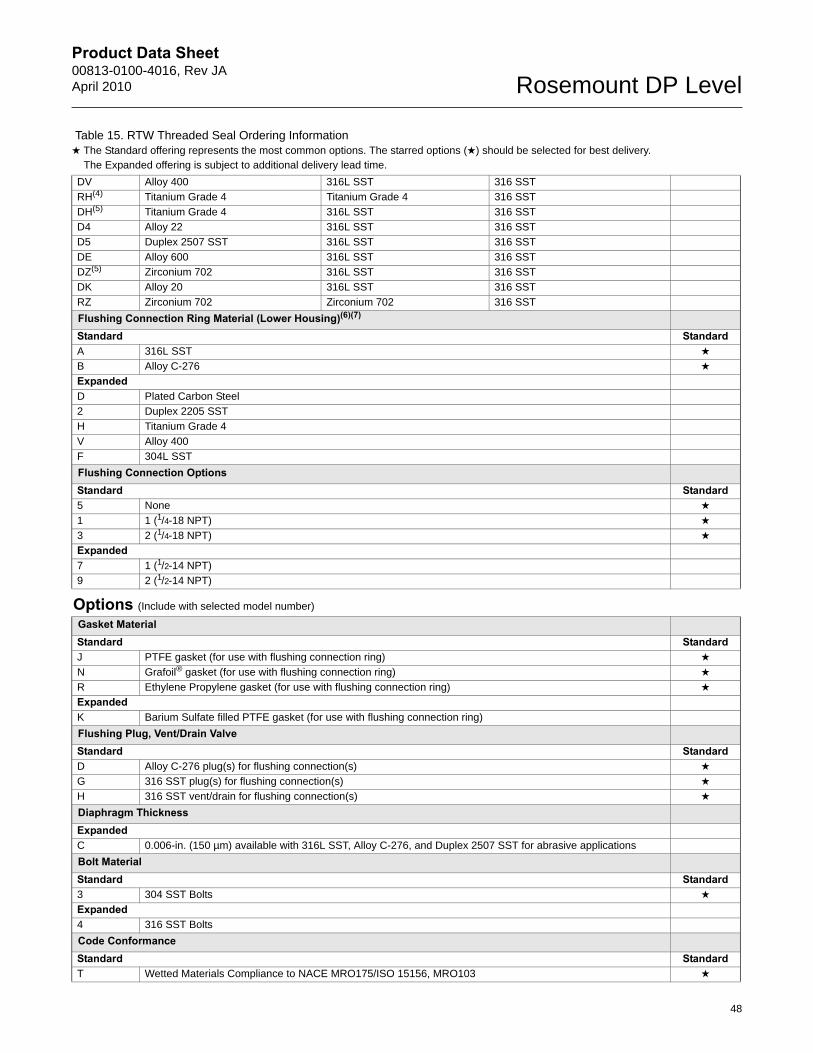
Product Data Sheet00813-0100-4016, Rev JAApril 2010 Rosemount DP Level
DV Alloy 400 316L SST 316 SST
RH(4) Titanium Grade 4 Titanium Grade 4 316 SST
DH(5) Titanium Grade 4 316L SST 316 SST
D4 Alloy 22 316L SST 316 SST
D5 Duplex 2507 SST 316L SST 316 SST
DE Alloy 600 316L SST 316 SST
DZ(5) Zirconium 702 316L SST 316 SST
DK Alloy 20 316L SST 316 SST
RZ Zirconium 702 Zirconium 702 316 SST
Flushing Connection Ring Material (Lower Housing)(6)(7)
Standard StandardA 316L SST ★
B Alloy C-276 ★
ExpandedD Plated Carbon Steel
2 Duplex 2205 SST
H Titanium Grade 4
V Alloy 400
F 304L SST
Flushing Connection OptionsStandard Standard5 None ★
1 1 (1/4-18 NPT) ★
3 2 (1/4-18 NPT) ★
Expanded7 1 (1/2-14 NPT)
9 2 (1/2-14 NPT)
Options (Include with selected model number)
Gasket MaterialStandard StandardJ PTFE gasket (for use with flushing connection ring) ★
N Grafoil® gasket (for use with flushing connection ring) ★
R Ethylene Propylene gasket (for use with flushing connection ring) ★
ExpandedK Barium Sulfate filled PTFE gasket (for use with flushing connection ring)
Flushing Plug, Vent/Drain ValveStandard StandardD Alloy C-276 plug(s) for flushing connection(s) ★
G 316 SST plug(s) for flushing connection(s) ★
H 316 SST vent/drain for flushing connection(s) ★
Diaphragm ThicknessExpandedC 0.006-in. (150 µm) available with 316L SST, Alloy C-276, and Duplex 2507 SST for abrasive applications
Bolt MaterialStandard Standard3 304 SST Bolts ★
Expanded4 316 SST Bolts
Code ConformanceStandard StandardT Wetted Materials Compliance to NACE MRO175/ISO 15156, MRO103 ★
Table 15. RTW Threaded Seal Ordering Information★ The Standard offering represents the most common options. The starred options (★) should be selected for best delivery.__The Expanded offering is subject to additional delivery lead time.
48
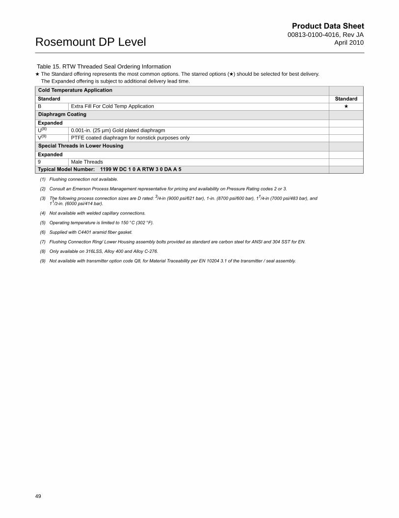
Product Data Sheet00813-0100-4016, Rev JA
April 2010Rosemount DP Level
Cold Temperature ApplicationStandard StandardB Extra Fill For Cold Temp Application ★
Diaphragm CoatingExpandedU(8) 0.001-in. (25 µm) Gold plated diaphragm
V(9) PTFE coated diaphragm for nonstick purposes only
Special Threads in Lower HousingExpanded9 Male Threads
Typical Model Number: 1199 W DC 1 0 A RTW 3 0 DA A 5
(1) Flushing connection not available.
(2) Consult an Emerson Process Management representative for pricing and availability on Pressure Rating codes 2 or 3.
(3) The following process connection sizes are D rated: 3/4-in (9000 psi/621 bar), 1-in. (8700 psi/600 bar), 11/4-in (7000 psi/483 bar), and 11/2-in. (6000 psi/414 bar).
(4) Not available with welded capillary connections.
(5) Operating temperature is limited to 150 °C (302 °F).
(6) Supplied with C4401 aramid fiber gasket.
(7) Flushing Connection Ring/ Lower Housing assembly bolts provided as standard are carbon steel for ANSI and 304 SST for EN.
(8) Only available on 316LSS, Alloy 400 and Alloy C-276.
(9) Not available with transmitter option code Q8, for Material Traceability per EN 10204 3.1 of the transmitter / seal assembly.
Table 15. RTW Threaded Seal Ordering Information★ The Standard offering represents the most common options. The starred options (★) should be selected for best delivery.__The Expanded offering is subject to additional delivery lead time.
49
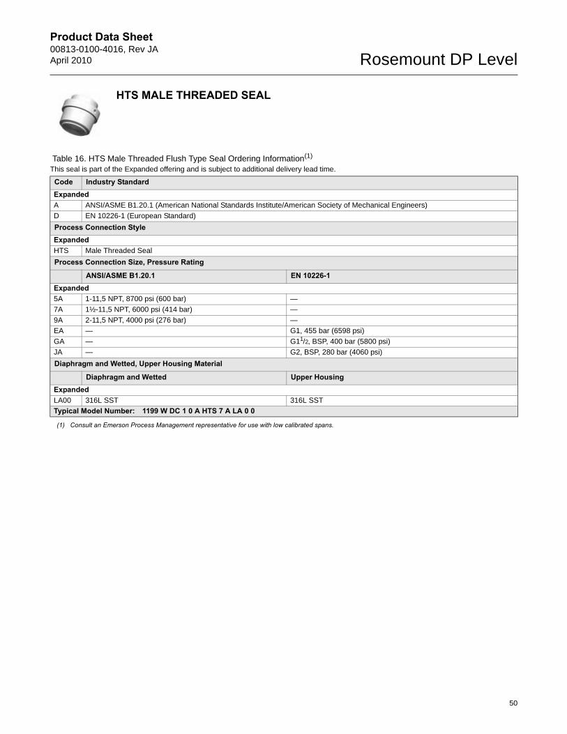
Product Data Sheet00813-0100-4016, Rev JAApril 2010 Rosemount DP Level
50
HTS MALE THREADED SEAL
Table 16. HTS Male Threaded Flush Type Seal Ordering Information(1)
This seal is part of the Expanded offering and is subject to additional delivery lead time.
Code Industry Standard ExpandedA ANSI/ASME B1.20.1 (American National Standards Institute/American Society of Mechanical Engineers)
D EN 10226-1 (European Standard)
Process Connection Style ExpandedHTS Male Threaded Seal
Process Connection Size, Pressure Rating
ANSI/ASME B1.20.1 EN 10226-1Expanded5A 1-11,5 NPT, 8700 psi (600 bar) —
7A 1½-11,5 NPT, 6000 psi (414 bar) —
9A 2-11,5 NPT, 4000 psi (276 bar) —
EA — G1, 455 bar (6598 psi)
GA — G11/2, BSP, 400 bar (5800 psi)
JA — G2, BSP, 280 bar (4060 psi)
Diaphragm and Wetted, Upper Housing Material
Diaphragm and Wetted Upper HousingExpandedLA00 316L SST 316L SST
Typical Model Number: 1199 W DC 1 0 A HTS 7 A LA 0 0
(1) Consult an Emerson Process Management representative for use with low calibrated spans.
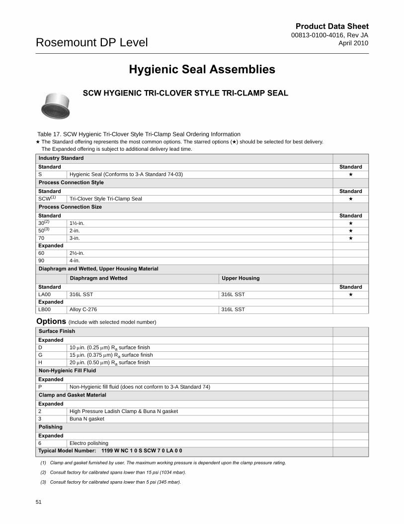
Product Data Sheet00813-0100-4016, Rev JA
April 2010Rosemount DP Level
51
Hygienic Seal Assemblies
SCW HYGIENIC TRI-CLOVER STYLE TRI-CLAMP SEAL
Table 17. SCW Hygienic Tri-Clover Style Tri-Clamp Seal Ordering Information★ The Standard offering represents the most common options. The starred options (★) should be selected for best delivery.__The Expanded offering is subject to additional delivery lead time.
Industry StandardStandard StandardS Hygienic Seal (Conforms to 3-A Standard 74-03) ★
Process Connection StyleStandard StandardSCW(1) Tri-Clover Style Tri-Clamp Seal ★
Process Connection Size Standard Standard30(2) 1½-in. ★
50(3) 2-in. ★
70 3-in. ★
Expanded60 2½-in.
90 4-in.
Diaphragm and Wetted, Upper Housing Material
Diaphragm and Wetted Upper HousingStandard StandardLA00 316L SST 316L SST ★
ExpandedLB00 Alloy C-276 316L SST
Options (Include with selected model number)
Surface FinishExpandedD 10 in. (0.25 m) Ra surface finish
G 15 in. (0.375 m) Ra surface finish
H 20 in. (0.50 m) Ra surface finish
Non-Hygienic Fill FluidExpandedP Non-Hygienic fill fluid (does not conform to 3-A Standard 74)
Clamp and Gasket MaterialExpanded2 High Pressure Ladish Clamp & Buna N gasket
3 Buna N gasket
PolishingExpanded6 Electro polishing
Typical Model Number: 1199 W NC 1 0 S SCW 7 0 LA 0 0
(1) Clamp and gasket furnished by user. The maximum working pressure is dependent upon the clamp pressure rating.
(2) Consult factory for calibrated spans lower than 15 psi (1034 mbar).
(3) Consult factory for calibrated spans lower than 5 psi (345 mbar).
Product Data Sheet00813-0100-4016, Rev JAApril 2010 Rosemount DP Level
52
SSW HYGIENIC TANK SPUD SEAL
Table 18. SSW Hygienic Tank Spud Seal Ordering Information★ The Standard offering represents the most common options. The starred options (★) should be selected for best delivery.__The Expanded offering is subject to additional delivery lead time.
Code Industry StandardStandard StandardS Hygienic Seal (Conforms to 3-A Standard 74-03) ★
Process Connection StyleStandard StandardSSW(1)
(1) Clamp and Ethylene Propylene o-ring (conforms to 3-A standard 74 and USP class VI) supplied.
Tank Spud Seal ★
Process Connection Size, Pressure RatingStandard StandardA0 4-in. Sch. 5 Tri-Clamp, 600 psi (41 bar) ★
Upper HousingStandard StandardA 316L SST ★
Diaphragm and Wetted, Extension MaterialDiaphragm and Wetted Extension
Standard StandardAL 316L SST(2)
(2) Diaphragm brazed and TIG-welded to extension.
316L SST(2) ★
ExpandedBB Alloy C-276 316L SST ★
Extension LengthStandard Standard2 2-in. ★
6 6-in. ★
Options (Include with selected model number)
Surface FinishExpandedG(3)
(3) Requires Option code 6, Electro polishing.
15 in. (0.375 m) diaphragm surface finishH 20 in(0.5 m) diaphragm surface finish
Diaphragm ThicknessExpandedC 0.006-in. (150 m)
Tanks SpudStandard Standard1 Tank Spud Included with Shipment ★
Non-Hygienic Fill FluidExpandedP Non-Hygienic fill fluid (Does not conform to 3-A Standard 74)
Non-Hygienic Fill FluidExpanded3 Buna N O-ring instead of Standard Ethylene Propylene O-ring (Conforms to 3-A Standard 74)4 Viton® O-ring, instead of Standard Ethylene Propylene O-ring (Conforms to 3-A Standard 74)
Non-Hygienic Fill FluidExpanded6 Electro polishingTypical Model Number: 1199 W NC 1 0 S SSW A 0 AA L 2
Product Data Sheet00813-0100-4016, Rev JA
April 2010Rosemount DP Level
STW HYGIENIC THIN WALL TANK SPUD SEAL
Table 19. STW Hygienic Thin Wall Tank Spud Seal Ordering InformationThis seal is part of the Expanded offering and is subject to additional delivery lead time.
Code Industry StandardExpandedS Hygienic Seal (Conforms to 3-A Standard 74-03)
Process Connection StyleExpandedSTW(1) Thin Wall Tank Spud Seal
Process Connection Size, Pressure RatingExpandedB0 4-in. Tri-Clamp, 600 psi (41 bar)
Diaphragm and Wetted, Extension Material
Diaphragm and Wetted ExtensionExpandedLA00 316L SST 316L SST
BB00 Alloy C-276 Alloy C-276
Options (Include with selected model number)
Surface FinishExpandedG(2) 15 in. (0.375 m) diaphragm surface finish
H 20 in(0.5 m) diaphragm surface finish
Non-Hygienic Fill FluidExpandedP Non-Hygienic fill fluid (Does not conform to 3-A Standard 74)
Non-Hygienic Fill FluidExpanded6 Electro polishing
Typical Model Number: 1199 W NC 1 0 S STW B 0 LA 0 0
(1) For tank walls up to 3/16-in. thick. Clamp and Ethylene Propylene o-ring supplied.
(2) Requires Option code 6, Electro polishing.
53
Product Data Sheet00813-0100-4016, Rev JAApril 2010 Rosemount DP Level
EES HYGIENIC FLANGED TANK SPUD EXTENDED SEAL
Table 20. EES Hygienic Flanged Tank Spud Extended Seal Ordering InformationThis seal is part of the Expanded offering and is subject to additional delivery lead time.
Code Industry StandardExpandedS Hygienic Seal (Conforms to 3-A Standard 74-03)
Process Connection Style ExpandedEES Flanged Tank Spud Seal
Process Connection Size, Pressure RatingExpandedGG DN 50, PN 40JG DN 80, PN 40
Diaphragm and Wetted, Extension MaterialDiaphragm and Wetted Extension
ExpandedLA 316L SST 316L SSTLB Alloy C-276 316L SST
Extension Length(1)
Expanded10 25 mm (1-in.)
Options (Include with selected model number)
Surface FinishExpandedG(2) 15 µ-in. (0.375 µm) Ra surface finishH 20 µ-in. (0.50 µm) Ra surface finish
Gasket MaterialExpanded1 Viton O-ring, instead of Standard Ethylene Propylene O-ring (Conforms to 3-A Standard 74)
Cold Temperature ApplicationExpandedB Extra Fill For Cold Temperature Application
Cold Temperature ApplicationExpanded6 Electro polishing Typical Model Number: 1199 W NC 1 0 S EES J G LA 1 0
(1) Other extension lengths are available upon request.
(2) Requires Option code 6, Electro polishing
54

Product Data Sheet00813-0100-4016, Rev JA
April 2010Rosemount DP Level
VCS TRI-CLAMP® IN-LINE SEAL
Table 21. VCS Tri-Clamp In-Line Seal Ordering InformationThis seal is part of the Expanded offering and is subject to additional delivery lead time.
Code Industry StandardExpandedS Hygienic Seal (Conforms to 3-A Standard 74-03)
Process Connection Style ExpandedVCS(1) In-Line Tri-Clover Style Tri-Clamp Seal
Process Connection SizeExpanded20(2) 1-in.30(3) 1½-in.50 2-in.70 3-in.90 4-in.
Diaphragm and Wetted, Upper Housing Material
Diaphragm and Wetted Upper HousingExpandedLA00 316L SST 316L SST
Options (Include with selected model number)
Surface FinishExpandedG(4) 15 in. (0.375 m) Ra surface finishH 20 µ-in. (0.50 µm) Ra surface finish
Non-Hygienic Fill FluidExpandedP Non-Hygienic fill fluid (does not conform to 3-A Standard 74)
PolishingExpanded6 Electro polishing Typical Model Number: 1199 W NC 1 0 S VCS 7 0 LA 0 0
(1) Gasket and clamp are furnished by the user. The maximum working pressure is dependent upon the clamp pressure rating.
(2) Consult factory for calibrated spans lower than 15 psi (1034 mbar).
(3) Consult factory for calibrated spans lower than 5 psi (345 mbar).
(4) Requires Option code 6, Electro polishing.
55
Product Data Sheet00813-0100-4016, Rev JAApril 2010 Rosemount DP Level
56
SVS VARIVENT COMPATIBLE HYGIENIC CONNECTION SEAL
Table 22. SVS Varivent® Compatible Hygienic Connection Seal Ordering InformationThis seal is part of the Expanded offering and is subject to additional delivery lead time.
Code Industry StandardExpandedS Hygienic Seal (Conforms to 3-A Standard 74-03)
Process Connection StyleExpandedSVS Tuchenhagen Varivent Compatible Seal
Process Connection Size ExpandedV0(1) Varivent® Type N DN 40-162
Diaphragm and Wetted, Upper Housing Material
Diaphragm and Wetted Upper HousingExpandedLA00 316L SST 316L SST
Options (Include with selected model number)
Non-Hygienic Fill FluidExpandedP Non-Hygienic fill fluid (does not conform to 3-A Standard 74)
Cold Temperature ApplicationExpandedB Extra Fill For Cold Temperature Application
PolishingExpanded6 Electro polishing
Typical Model Number: 1199 W NC 1 0 S SVS V 0 LA 0 0
(1) Consult factory for calibrated spans lower than 15 psi (1034 mbar).
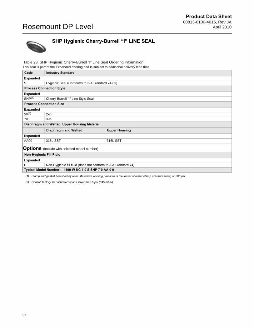
Product Data Sheet00813-0100-4016, Rev JA
April 2010Rosemount DP Level
57
SHP Hygienic Cherry-Burrell “I” LINE SEAL
Table 23. SHP Hygienic Cherry-Burrell “I” Line Seal Ordering InformationThis seal is part of the Expanded offering and is subject to additional delivery lead time.
Code Industry StandardExpandedS Hygienic Seal (Conforms to 3-A Standard 74-03)
Process Connection StyleExpandedSHP(1) Cherry-Burrell “I” Line Style Seal
Process Connection SizeExpanded50(2) 2-in.
70 3-in.
Diaphragm and Wetted, Upper Housing Material
Diaphragm and Wetted Upper HousingExpandedAA00 316L SST 316L SST
Options (Include with selected model number)
Non-Hygienic Fill FluidExpandedP Non-Hygienic fill fluid (does not conform to 3-A Standard 74)
Typical Model Number: 1199 W NC 1 0 S SHP 7 0 AA 0 0
(1) Clamp and gasket furnished by user. Maximum working pressure is the lesser of either clamp pressure rating or 500 psi.
(2) Consult factory for calibrated spans lower than 5 psi (345 mbar).
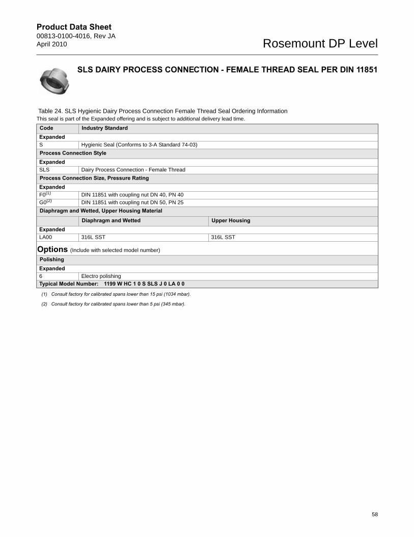
Product Data Sheet00813-0100-4016, Rev JAApril 2010 Rosemount DP Level
SLS DAIRY PROCESS CONNECTION - FEMALE THREAD SEAL PER DIN 11851
Table 24. SLS Hygienic Dairy Process Connection Female Thread Seal Ordering InformationThis seal is part of the Expanded offering and is subject to additional delivery lead time.
Code Industry StandardExpandedS Hygienic Seal (Conforms to 3-A Standard 74-03)
Process Connection StyleExpandedSLS Dairy Process Connection - Female Thread
Process Connection Size, Pressure RatingExpandedF0(1)
(1) Consult factory for calibrated spans lower than 15 psi (1034 mbar).
DIN 11851 with coupling nut DN 40, PN 40
G0(2)
(2) Consult factory for calibrated spans lower than 5 psi (345 mbar).
DIN 11851 with coupling nut DN 50, PN 25
Diaphragm and Wetted, Upper Housing Material
Diaphragm and Wetted Upper HousingExpandedLA00 316L SST 316L SST
Options (Include with selected model number)
PolishingExpanded6 Electro polishing
Typical Model Number: 1199 W HC 1 0 S SLS J 0 LA 0 0
58
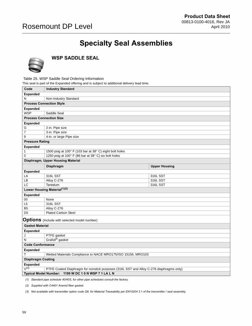
Product Data Sheet00813-0100-4016, Rev JA
April 2010Rosemount DP Level
Specialty Seal Assemblies
WSP SADDLE SEAL
Table 25. WSP Saddle Seal Ordering InformationThis seal is part of the Expanded offering and is subject to additional delivery lead time.
Code Industry StandardExpandedN Non-Industry Standard
Process Connection StyleExpandedWSP Saddle Seal
Process Connection SizeExpandedG 2-in. Pipe size7 3-in. Pipe size9 4-in. or large Pipe size
Pressure RatingExpanded1 1500 psig at 100° F (103 bar at 38° C) eight bolt holes0 1250 psig at 100° F (86 bar at 38° C) six bolt holes
Diaphragm, Upper Housing MaterialDiaphragm Upper Housing
ExpandedLA 316L SST 316L SSTLB Alloy C-276 316L SSTLC Tantalum 316L SST
Lower Housing Material(1)(2)
Expanded00 NoneL5 316L SSTB5 Alloy C-276D5 Plated Carbon Steel
Options (Include with selected model number)
Gasket Material ExpandedJ PTFE gasketN Grafoil® gasket
Code ConformanceExpandedT Wetted Materials Compliance to NACE MRO175/ISO 15156, MRO103
Diaphragm Coating ExpandedV(3) PTFE Coated Diaphragm for nonstick purposes (316L SST and Alloy C-276 diaphragms only)Typical Model Number: 1199 W DC 1 0 N WSP 7 1 LA L N
(1) Standard pipe schedule 40/40S, for other pipe schedules consult the factory.
(2) Supplied with C4401 Aramid fiber gasket.
(3) Not available with transmitter option code Q8, for Material Traceability per EN10204 3.1 of the transmitter / seal assembly.
59
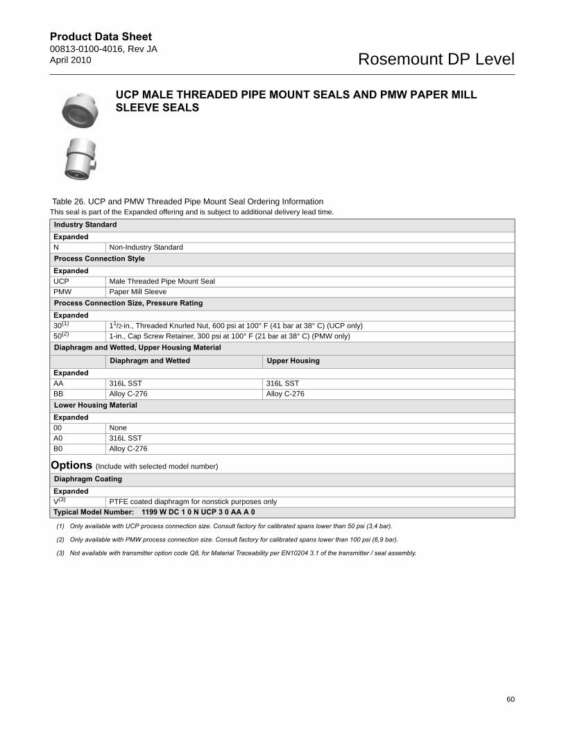
Product Data Sheet00813-0100-4016, Rev JAApril 2010 Rosemount DP Level
UCP MALE THREADED PIPE MOUNT SEALS AND PMW PAPER MILL SLEEVE SEALS
Table 26. UCP and PMW Threaded Pipe Mount Seal Ordering InformationThis seal is part of the Expanded offering and is subject to additional delivery lead time.
Industry StandardExpandedN Non-Industry Standard
Process Connection StyleExpandedUCP Male Threaded Pipe Mount Seal
PMW Paper Mill Sleeve
Process Connection Size, Pressure RatingExpanded30(1) 11/2-in., Threaded Knurled Nut, 600 psi at 100° F (41 bar at 38° C) (UCP only)
50(2) 1-in., Cap Screw Retainer, 300 psi at 100° F (21 bar at 38° C) (PMW only)
Diaphragm and Wetted, Upper Housing Material
Diaphragm and Wetted Upper HousingExpandedAA 316L SST 316L SST
BB Alloy C-276 Alloy C-276
Lower Housing MaterialExpanded00 None
A0 316L SST
B0 Alloy C-276
Options (Include with selected model number)
Diaphragm CoatingExpandedV(3) PTFE coated diaphragm for nonstick purposes only
Typical Model Number: 1199 W DC 1 0 N UCP 3 0 AA A 0
(1) Only available with UCP process connection size. Consult factory for calibrated spans lower than 50 psi (3,4 bar).
(2) Only available with PMW process connection size. Consult factory for calibrated spans lower than 100 psi (6,9 bar).
(3) Not available with transmitter option code Q8, for Material Traceability per EN10204 3.1 of the transmitter / seal assembly.
60
Product Data Sheet00813-0100-4016, Rev JA
April 2010Rosemount DP Level
CTW CHEMICAL TEE SEAL
Table 27. CTW Chemical Tee Seal Ordering InformationThis seal is part of the Expanded offering and is subject to additional delivery lead time.
Code Industry StandardExpandedN Non-Industry Standard
Process Connection StyleExpandedCTW Chemical Tee Seal
Maximum Working Pressure (Flange Rating)Expanded20 300 psi (21 bar)
Diaphragm and Wetted, Upper Housing Material
Diaphragm and Wetted Upper HousingExpandedAA 316L SST 316L SST
BB Alloy C-276 Alloy C-276
Lower Housing Expanded00 None
Options (Include with selected model number)
Code ConformanceExpandedT Wetted Materials Compliance to NACE MRO175/ISO 15156, MRO103
Diaphragm Coating ExpandedV(1) PTFE coated diaphragm for nonstick purposes only
Typical Model Number: 1199 W NC 1 0 N CTW 2 0 AA 0 0
(1) Not available with transmitter option code Q8, for Material Traceability per EN10204 3.1 of the transmitter / seal assembly.
61
Product Data Sheet00813-0100-4016, Rev JAApril 2010 Rosemount DP Level
TFS WAFER STYLE IN-LINE SEAL
Table 28. TFS Wafer Style In-Line Seal Ordering InformationThis seal is part of the Expanded offering and is subject to additional delivery lead time.
Code Industry Standard ExpandedA ANSI/ASME B16.5 (American National Standards Institute/American Society of Mechanical Engineers)D EN 1092-1 (European Standard)
Process Connection StyleExpandedTFS Wafer Style In-Line Seal
Process Connection Size
ANSI/ASME B16.5 EN 1092-1ExpandedG 2-in. DN 507 3-in. —J — DN 809 4-in. —2(1) 1-in. —4(2) 1½-in. —D(1) — DN 25F(2) — DN 40K — DN 100
Pressure Rating Expanded0 Flange not supplied, seal rated to carbon steel Class 2500, PN 160
Diaphragm and Wetted, Upper Housing Material
Diaphragm and Wetted Upper HousingExpandedLA 316L SST 316L SSTLB Alloy C-276 316L SST
Housing Body LengthExpanded00 3.54-in. (90 mm)Typical Model Number: 1199 W DC 1 0 A TFS 7 0 LA 0 0
(1) Consult factory for calibrated spans lower than 15 psi (1034 mbar).
(2) Consult factory for calibrated spans lower than 5 psi (345 mbar).
62
Product Data Sheet00813-0100-4016, Rev JA
April 2010Rosemount DP Level
WFW FLOW-THRU FLANGED SEAL
Table 29. WFW Flow-Thru Flanged Seal Ordering InformationThis seal is part of the Expanded offering and is subject to additional delivery lead time.
Code Industry StandardExpandedA ANSI/ASME B16.5 (American National Standards Institute/American Society of Mechanical Engineers)
Process Connection StyleExpandedWFW(1) Flow-Thru Flanged Seal
Process Connection Size(2)
ExpandedG 2-in.
7 3-in.
2 1-in.
Flange Rating(2)
Expanded1 Class 150(2)
Diaphragm, Upper Housing Material
Diaphragm Upper Housing(2)
ExpandedLA 316L SST 316L SST
Lower Housing Material(1)
ExpandedL 316L SST
Pipe Schedule(2)
ExpandedN 40/40S
Options (Include with selected model number)
Gasket MaterialExpandedJ PTFE O-ring
K Barium Sulfate filled PTFE gasket
N Grafoil® gasket
R Ethylene Propylene gasket
Bolt MaterialExpanded3 304 SST bolts
Code ConformanceExpandedT Wetted Materials Compliance to NACE MRO175/ISO 15156, MRO103
Cold Temperature ApplicationExpandedB Extra Fill For Cold Temperature Application
Typical Model Number: 1199 W DC 1 0 A TFS 7 0 LA 0 0
(1) Supplied with C4401 Aramid fiber gasket.
(2) Consult factory for special process connection sizes, flange pressure ratings, diaphragm/lower housing materials, and pipe schedules.
63
Product Data Sheet00813-0100-4016, Rev JAApril 2010 Rosemount DP Level
Specifications
LIQUID LEVEL TRANSMITTER SPECIFICATIONS
Performance SpecificationsFor zero-based spans, reference conditions, silicone oil fill, glass-filled PTFE o-rings, SST materials, Coplanar flange (3051SMV, 3051S_C) or 1/2-in.- 14 NPT (3051S_T) process connections, digital trim values set to equal range points.
Conformance to Specification (±3 (Sigma))Technology leadership, advanced manufacturing techniques, and statistical process control ensure measurement specification conformance to ±3or better.
Warranty(1)
Dynamic PerformanceSee Instrument Toolkit®.
Ambient Temperature EffectSee Instrument Toolkit.
Reference Accuracy(1)
Stated reference accuracy equations include terminal based linearity, hysteresis, and repeatability, but does not include analog output reference accuracy of ±0.005% of span.
For FOUNDATION™ fieldbus and wireless devices, use calibrated range in place of span.
(1) Stated reference accuracy equations include terminal based linearity, hysteresis, and repeatability, but does not include analog only reference accuracy of ±0.005% of span.
3051S_L ±0.065% of span;For spans less than 10:1,
3051LAll Ranges ±0.075% of span
For spans less than 10:1, accuracy =
2051LRanges 2-4 ±0.075% of span
For spans less than 10:1, accuracy =
0.015 0.005+URLspan-------------- % of span
0.025 0.005+URLSpan--------------- % of Span
0.025 0.005+URLSpan--------------- % of Span
Models(1) Ultra Classic3051S_L 12-year limited warranty(2) 1-year limited warranty(3)
(1) Warranty details can be found in Emerson Process Management Terms & Conditions of Sale, Document 63445, Rev G (10/06).
(2) Rosemount Ultra and Ultra for Flow transmitters have a limited warranty of twelve (12) years from date of shipment. All other provisions of Emerson Process Management standard limited warranty remain the same.
(3) Goods are warranted for twelve (12) months from the date of initial installation or eighteen (18) months from the date of shipment by seller, whichever period expires first.
64
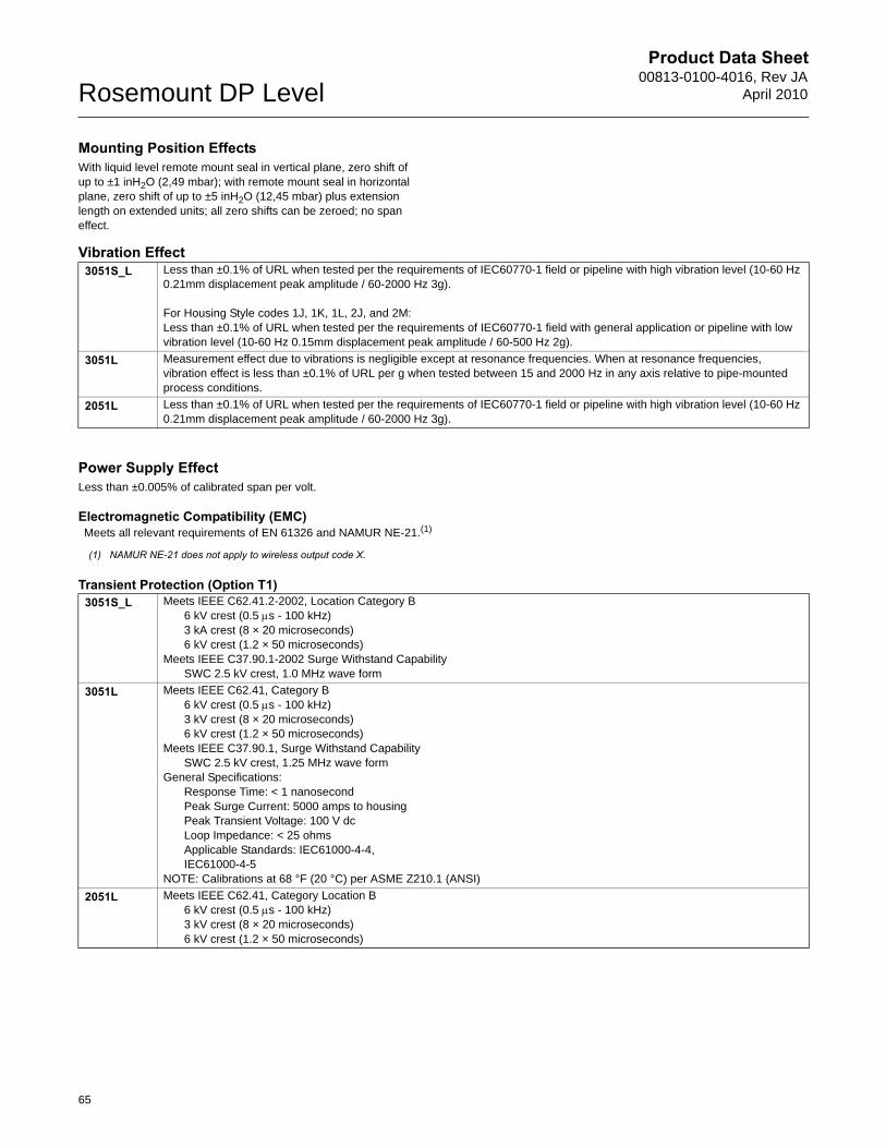
Product Data Sheet00813-0100-4016, Rev JA
April 2010Rosemount DP Level
Mounting Position EffectsWith liquid level remote mount seal in vertical plane, zero shift of up to ±1 inH2O (2,49 mbar); with remote mount seal in horizontal plane, zero shift of up to ±5 inH2O (12,45 mbar) plus extension length on extended units; all zero shifts can be zeroed; no span effect.
Vibration Effect
Power Supply EffectLess than ±0.005% of calibrated span per volt.
Electromagnetic Compatibility (EMC)
Transient Protection (Option T1)
3051S_L Less than ±0.1% of URL when tested per the requirements of IEC60770-1 field or pipeline with high vibration level (10-60 Hz 0.21mm displacement peak amplitude / 60-2000 Hz 3g).
For Housing Style codes 1J, 1K, 1L, 2J, and 2M:Less than ±0.1% of URL when tested per the requirements of IEC60770-1 field with general application or pipeline with low vibration level (10-60 Hz 0.15mm displacement peak amplitude / 60-500 Hz 2g).
3051L Measurement effect due to vibrations is negligible except at resonance frequencies. When at resonance frequencies, vibration effect is less than ±0.1% of URL per g when tested between 15 and 2000 Hz in any axis relative to pipe-mounted process conditions.
2051L Less than ±0.1% of URL when tested per the requirements of IEC60770-1 field or pipeline with high vibration level (10-60 Hz 0.21mm displacement peak amplitude / 60-2000 Hz 3g).
Meets all relevant requirements of EN 61326 and NAMUR NE-21.(1)
(1) NAMUR NE-21 does not apply to wireless output code X.
3051S_L Meets IEEE C62.41.2-2002, Location Category B6 kV crest (0.5 s - 100 kHz)3 kA crest (8 × 20 microseconds)6 kV crest (1.2 × 50 microseconds)
Meets IEEE C37.90.1-2002 Surge Withstand CapabilitySWC 2.5 kV crest, 1.0 MHz wave form
3051L Meets IEEE C62.41, Category B6 kV crest (0.5 s - 100 kHz)3 kV crest (8 × 20 microseconds)6 kV crest (1.2 × 50 microseconds)
Meets IEEE C37.90.1, Surge Withstand CapabilitySWC 2.5 kV crest, 1.25 MHz wave form
General Specifications:Response Time: < 1 nanosecondPeak Surge Current: 5000 amps to housingPeak Transient Voltage: 100 V dcLoop Impedance: < 25 ohmsApplicable Standards: IEC61000-4-4,IEC61000-4-5
NOTE: Calibrations at 68 °F (20 °C) per ASME Z210.1 (ANSI)
2051L Meets IEEE C62.41, Category Location B6 kV crest (0.5 s - 100 kHz)3 kV crest (8 × 20 microseconds)6 kV crest (1.2 × 50 microseconds)
65
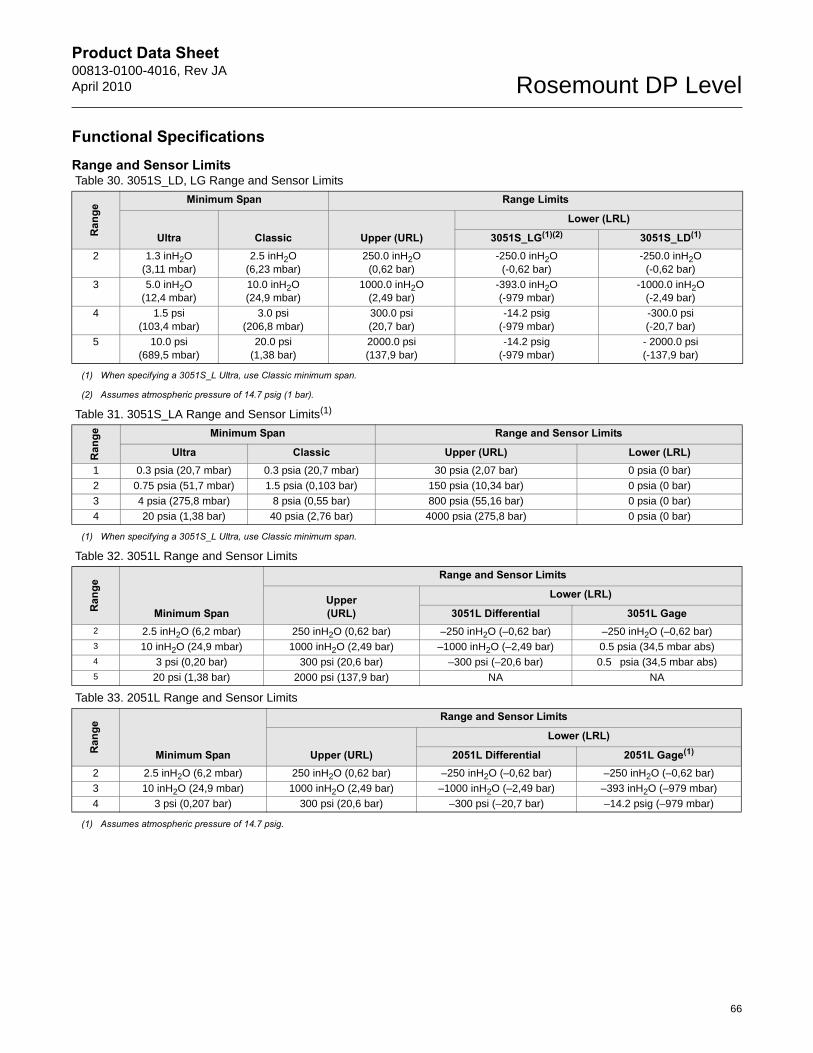
Product Data Sheet00813-0100-4016, Rev JAApril 2010 Rosemount DP Level
66
Functional SpecificationsRange and Sensor Limits Table 30. 3051S_LD, LG Range and Sensor Limits
Ran
ge
Minimum Span Range Limits
Ultra Classic Upper (URL)
Lower (LRL)
3051S_LG(1)(2) 3051S_LD(1)
2 1.3 inH2O (3,11 mbar)
2.5 inH2O (6,23 mbar)
250.0 inH2O(0,62 bar)
-250.0 inH2O(-0,62 bar)
-250.0 inH2O(-0,62 bar)
3 5.0 inH2O(12,4 mbar)
10.0 inH2O (24,9 mbar)
1000.0 inH2O (2,49 bar)
-393.0 inH2O(-979 mbar)
-1000.0 inH2O (-2,49 bar)
4 1.5 psi(103,4 mbar)
3.0 psi (206,8 mbar)
300.0 psi (20,7 bar)
-14.2 psig(-979 mbar)
-300.0 psi(-20,7 bar)
5 10.0 psi(689,5 mbar)
20.0 psi (1,38 bar)
2000.0 psi (137,9 bar)
-14.2 psig(-979 mbar)
- 2000.0 psi(-137,9 bar)
(1) When specifying a 3051S_L Ultra, use Classic minimum span.
(2) Assumes atmospheric pressure of 14.7 psig (1 bar).
Table 31. 3051S_LA Range and Sensor Limits(1)
Ran
ge Minimum Span Range and Sensor Limits
Upper (URL) Lower (LRL)Ultra Classic1 0.3 psia (20,7 mbar) 0.3 psia (20,7 mbar) 30 psia (2,07 bar) 0 psia (0 bar)
2 0.75 psia (51,7 mbar) 1.5 psia (0,103 bar) 150 psia (10,34 bar) 0 psia (0 bar)
3 4 psia (275,8 mbar) 8 psia (0,55 bar) 800 psia (55,16 bar) 0 psia (0 bar)
4 20 psia (1,38 bar) 40 psia (2,76 bar) 4000 psia (275,8 bar) 0 psia (0 bar)
(1) When specifying a 3051S_L Ultra, use Classic minimum span.
Table 32. 3051L Range and Sensor Limits
Ran
ge
Minimum Span
Range and Sensor Limits
Upper (URL)
Lower (LRL)
3051L Differential 3051L Gage2 2.5 inH2O (6,2 mbar) 250 inH2O (0,62 bar) –250 inH2O (–0,62 bar) –250 inH2O (–0,62 bar)3 10 inH2O (24,9 mbar) 1000 inH2O (2,49 bar) –1000 inH2O (–2,49 bar) 0.5 psia (34,5 mbar abs)4 3 psi (0,20 bar) 300 psi (20,6 bar) –300 psi (–20,6 bar) 0.5 psia (34,5 mbar abs)5 20 psi (1,38 bar) 2000 psi (137,9 bar) NA NA
Table 33. 2051L Range and Sensor Limits
Ran
ge
Minimum Span
Range and Sensor Limits
Upper (URL)
Lower (LRL)
2051L Differential 2051L Gage(1)
2 2.5 inH2O (6,2 mbar) 250 inH2O (0,62 bar) –250 inH2O (–0,62 bar) –250 inH2O (–0,62 bar)
3 10 inH2O (24,9 mbar) 1000 inH2O (2,49 bar) –1000 inH2O (–2,49 bar) –393 inH2O (–979 mbar)
4 3 psi (0,207 bar) 300 psi (20,6 bar) –300 psi (–20,7 bar) –14.2 psig (–979 mbar)
(1) Assumes atmospheric pressure of 14.7 psig.
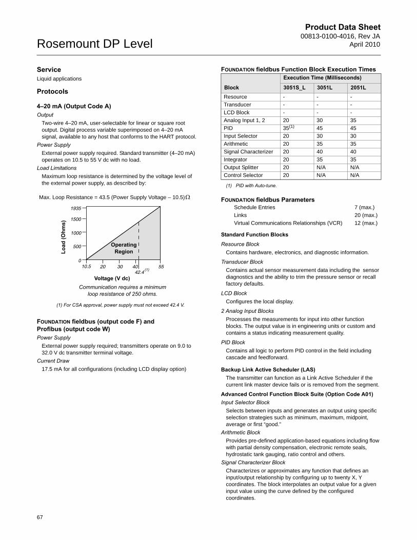
Product Data Sheet00813-0100-4016, Rev JA
April 2010Rosemount DP Level
ServiceLiquid applications
Protocols
4–20 mA (Output Code A)Output
Two-wire 4–20 mA, user-selectable for linear or square root output. Digital process variable superimposed on 4–20 mA signal, available to any host that conforms to the HART protocol.
Power SupplyExternal power supply required. Standard transmitter (4–20 mA) operates on 10.5 to 55 V dc with no load.
Load Limitations Maximum loop resistance is determined by the voltage level of the external power supply, as described by:
FOUNDATION fieldbus (output code F) and Profibus (output code W)Power Supply
External power supply required; transmitters operate on 9.0 to 32.0 V dc transmitter terminal voltage.
Current Draw17.5 mA for all configurations (including LCD display option)
FOUNDATION fieldbus Function Block Execution Times
FOUNDATION fieldbus Parameters
Standard Function Blocks
Resource BlockContains hardware, electronics, and diagnostic information.
Transducer BlockContains actual sensor measurement data including the sensor diagnostics and the ability to trim the pressure sensor or recall factory defaults.
LCD BlockConfigures the local display.
2 Analog Input BlocksProcesses the measurements for input into other function blocks. The output value is in engineering units or custom and contains a status indicating measurement quality.
PID Block Contains all logic to perform PID control in the field including cascade and feedforward.
Backup Link Active Scheduler (LAS)The transmitter can function as a Link Active Scheduler if the current link master device fails or is removed from the segment.
Advanced Control Function Block Suite (Option Code A01)Input Selector Block
Selects between inputs and generates an output using specific selection strategies such as minimum, maximum, midpoint, average or first “good.”
Arithmetic BlockProvides pre-defined application-based equations including flow with partial density compensation, electronic remote seals, hydrostatic tank gauging, ratio control and others.
Signal Characterizer BlockCharacterizes or approximates any function that defines an input/output relationship by configuring up to twenty X, Y coordinates. The block interpolates an output value for a given input value using the curve defined by the configured coordinates.
Voltage (V dc)
Load
(Ohm
s)
Communication requires a minimum loop resistance of 250 ohms.
(1) For CSA approval, power supply must not exceed 42.4 V.
Max. Loop Resistance = 43.5 (Power Supply Voltage – 10.5)
OperatingRegion
Block
Execution Time (Milliseconds)
3051S_L 3051L 2051LResource - - -
Transducer - - -
LCD Block - - -
Analog Input 1, 2 20 30 35
PID 35(1)
(1) PID with Auto-tune.
45 45
Input Selector 20 30 30
Arithmetic 20 35 35
Signal Characterizer 20 40 40
Integrator 20 35 35
Output Splitter 20 N/A N/A
Control Selector 20 N/A N/A
Schedule Entries 7 (max.)
Links 20 (max.)
Virtual Communications Relationships (VCR) 12 (max.)
67

Product Data Sheet00813-0100-4016, Rev JAApril 2010 Rosemount DP Level
Integrator BlockCompares the integrated or accumulated value from one or two variables to pre-trip and trip limits and generates discrete output signals when the limits are reached. This block is useful for calculating total flow, total mass, or volume over time.
FOUNDATION fieldbus Diagnostics Suite (Option Code D01)The FOUNDATION fieldbus Diagnostics provide Abnormal Situation Prevention (ASP) indication. The integral statistical process monitoring (SPM) technology calculates the mean and standard deviation of the process variable 22 times per second. The 3051S_L and 3051L use these values and highly flexible configuration options for customization to detect many user-defined or application specific abnormal situations (e.g. detecting plugged impulse lines and fluid composition change).
3051S_L Wireless Self-Organizing NetworksOutputWirelessHART, 2.4 GHz DSSS. Wireless, 2.4 GHz DSSS or 900 MHz FHSS.
Local Display (WirelessHART only)The optional five-digit LCD can display user-selectable information such as primary variable in engineering units, percent of range, sensor module temperature, and electronics temperature. Display updates at up to once per minute.
Local DisplayThe optional five-digit LCD can display primary variable in engineering units. Display updates at update rate up to once per minute.
Update RateWirelessHART, user selectable 8 sec. to 60 min.Wireless, user selectable 15 sec. to 60 min.
Power Module (WirelessHART only)
Power Module
Overpressure LimitsLimit is 0 psia to the flange rating or sensor rating, whichever is lower.
Temperature Limits
Ambient
Storage
Field replaceable, keyed connection eliminates the risk of incorrect installation, Intrinsically Safe Lithium-thionyl chloride Power Module with polybutadine terephthalate (PBT) enclosure. Ten-year life at one minute update rate.(1)
(1) Reference conditions are 70 °F (21 °C), and routing data for three additional network devices.NOTE: Continuous exposure to ambient temperature limits of -40 °F or 185 °F (-40 °C or 85 °C) may reduce specified life by less than 20 percent.
Field replaceable, keyed connection eliminates the risk of incorrect installation, Intrinsically Safe Lithium-thionyl chloride Power Module with polybutadine terephthalate (PBT) enclosure. Five-year life at one minute update rate, ten-year life at ten minute update rate.(1)
(1) Reference conditions are 70 °F (21 °C), and routing data for three additional network devices.NOTE: Continuous exposure to ambient temperature limits of -40 °F or 185 °F (-40 °C or 85 °C) may reduce specified life by less than 20 percent.
TABLE 34. 3051L and Level Flange Rating Limits
Standard Type CS Rating SST RatingANSI/ASME Class 150 285 psig 275 psigANSI/ASME Class 300 740 psig 720 psigANSI/ASME Class 600 1480 psig 1440 psig
At 100 °F (38 °C), the rating decreaseswith increasing temperature, per ANSI/ASME B16.5.DIN PN 10–40 40 bar 40 barDIN PN 10/16 16 bar 16 barDIN PN 25/40 40 bar 40 bar
At 248 °F (120 °C), the rating decreases with increasing temperature, per DIN 2401.
-40 to 185 °F (-40 to 85 °C)With LCD display(1): -40 to 175 °F (-40 to 80 °C)With option code P0: -20 to 185 °F (-29 to 85 °C)
(1) LCD display may not be readable and LCD updates will be slower at temperatures below -4 °F (-20 °C).
-50 to 185 °F (-46 to 85 °C)With LCD display: -40 to 185 °F (-40 to 85 °C)With Wireless Output: -40 to 185 °F (-40 to 85 °C)
68
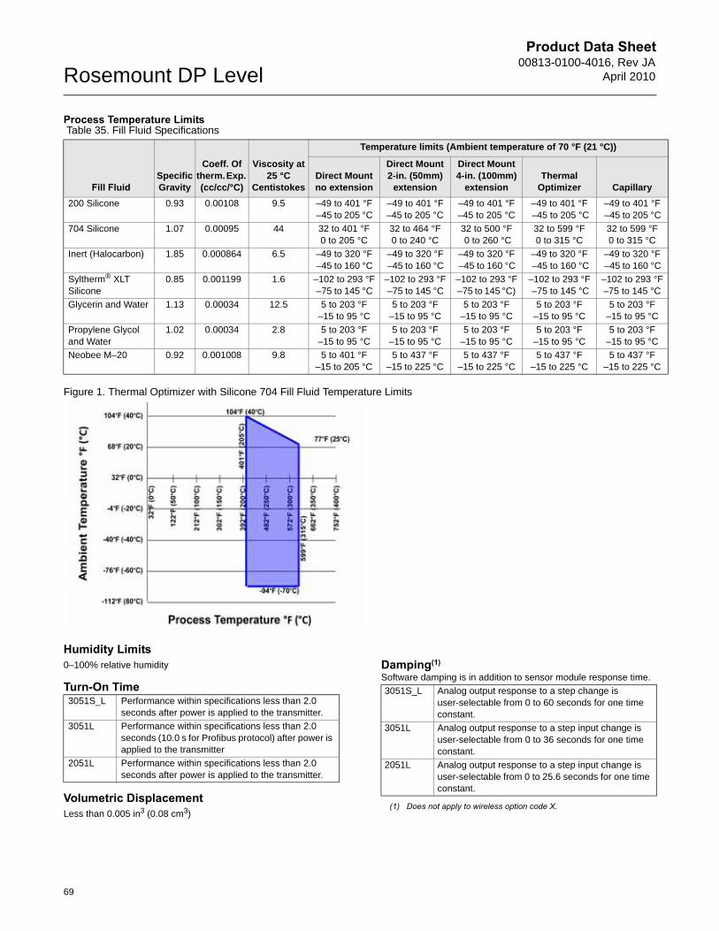
Product Data Sheet00813-0100-4016, Rev JA
April 2010Rosemount DP Level
Process Temperature Limits
Figure 1. Thermal Optimizer with Silicone 704 Fill Fluid Temperature Limits
Humidity Limits0–100% relative humidity
Turn-On Time
Volumetric DisplacementLess than 0.005 in3 (0.08 cm3)
Table 35. Fill Fluid Specifications
Fill FluidSpecific Gravity
Coeff. Of therm. Exp. (cc/cc/°C)
Viscosity at 25 °C
Centistokes
Temperature limits (Ambient temperature of 70 °F (21 °C))
Direct Mount no extension
Direct Mount 2-in. (50mm)
extension
Direct Mount 4-in. (100mm)
extensionThermal
Optimizer Capillary
200 Silicone 0.93 0.00108 9.5 –49 to 401 °F –45 to 205 °C
–49 to 401 °F–45 to 205 °C
–49 to 401 °F –45 to 205 °C
–49 to 401 °F –45 to 205 °C
–49 to 401 °F –45 to 205 °C
704 Silicone 1.07 0.00095 44 32 to 401 °F0 to 205 °C
32 to 464 °F0 to 240 °C
32 to 500 °F 0 to 260 °C
32 to 599 °F 0 to 315 °C
32 to 599 °F0 to 315 °C
Inert (Halocarbon) 1.85 0.000864 6.5 –49 to 320 °F –45 to 160 °C
–49 to 320 °F –45 to 160 °C
–49 to 320 °F –45 to 160 °C
–49 to 320 °F –45 to 160 °C
–49 to 320 °F –45 to 160 °C
Syltherm® XLT Silicone
0.85 0.001199 1.6 –102 to 293 °F –75 to 145 °C
–102 to 293 °F –75 to 145 °C
–102 to 293 °F –75 to 145 °C)
–102 to 293 °F –75 to 145 °C
–102 to 293 °F–75 to 145 °C
Glycerin and Water 1.13 0.00034 12.5 5 to 203 °F–15 to 95 °C
5 to 203 °F–15 to 95 °C
5 to 203 °F–15 to 95 °C
5 to 203 °F–15 to 95 °C
5 to 203 °F–15 to 95 °C
Propylene Glycol and Water
1.02 0.00034 2.8 5 to 203 °F–15 to 95 °C
5 to 203 °F–15 to 95 °C
5 to 203 °F–15 to 95 °C
5 to 203 °F–15 to 95 °C
5 to 203 °F–15 to 95 °C
Neobee M–20 0.92 0.001008 9.8 5 to 401 °F–15 to 205 °C
5 to 437 °F–15 to 225 °C
5 to 437 °F–15 to 225 °C
5 to 437 °F–15 to 225 °C
5 to 437 °F–15 to 225 °C
3051S_L Performance within specifications less than 2.0 seconds after power is applied to the transmitter.
3051L Performance within specifications less than 2.0 seconds (10.0 s for Profibus protocol) after power is applied to the transmitter
2051L Performance within specifications less than 2.0 seconds after power is applied to the transmitter.
Damping(1)
Software damping is in addition to sensor module response time.
(1) Does not apply to wireless option code X.
3051S_L Analog output response to a step change is user-selectable from 0 to 60 seconds for one time constant.
3051L Analog output response to a step input change is user-selectable from 0 to 36 seconds for one time constant.
2051L Analog output response to a step input change is user-selectable from 0 to 25.6 seconds for one time constant.
69
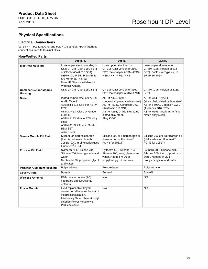
Product Data Sheet00813-0100-4016, Rev JAApril 2010 Rosemount DP Level
70
Physical SpecificationsElectrical Connections1/2–14 NPT, PG 13.5, G1/2, and M20 × 1.5 conduit. HART interface connections fixed to terminal block.
Non-Wetted Parts3051S_L 3051L 2051L
Electrical Housing Low-copper aluminum alloy or SST: CF-3M (Cast 316L SST) or CF-8M (Cast 316 SST) NEMA 4X, IP 66, IP 68 (66 ft (20 m) for 168 hours)Note: IP 68 not available with Wireless Output.
Low-copper aluminum or CF-3M (Cast version of 316L SST, material per ASTM-A743). NEMA 4X, IP 65, IP 66
Low-copper aluminum or CF-8M (Cast version of 316 SST). Enclosure Type 4X, IP 65, IP 66, IP68
Coplanar Sensor Module Housing
SST: CF-3M (Cast 316L SST) CF-3M (Cast version of 316L SST, material per ASTM-A743)
CF-3M (Cast version of 316L SST)
Bolts Plated carbon steel per ASTM A449, Type 1Austenitic 316 SST per ASTM F593ASTM A453, Class D, Grade 660 SSTASTM A193, Grade B7M alloy steelASTM A193, Class 2, Grade B8M SSTAlloy K-500
ASTM A449, Type 1 (zinc-cobalt plated carbon steel)ASTM F593G, Condition CW1 (Austenitic 316 SST)ASTM A193, Grade B7M (zinc plated alloy steel)Alloy K-500
ASTM A449, Type 1 (zinc-cobalt plated carbon steel)ASTM F593G, Condition CW1 (Austenitic 316 SST)ASTM A193, Grade B7M (zinc plated alloy steel)
Sensor Module Fill Fluid Silicone or inert halocarbon (Inert is not available with 3051S_CA). In-Line series uses Fluorinert® FC-43.
Silicone 200 or Fluorocarbon oil (Halocarbon or Fluorinert® FC-43 for 3051T)
Silicone 200 or Fluorocarbon oil (Halocarbon or Fluorinert® FC-43 for 2051T)
Process Fill Fluid Syltherm XLT, Silicone 704, Silicone 200, inert, glycerin and water, Neobee M-20, propylene glycol and water.
Syltherm XLT, Silicone 704, Silicone 200, inert, glycerin and water, Neobee M-20 or propylene glycol and water
Syltherm XLT, Silicone 704, Silicone 200, inert, glycerin and water, Neobee M-20 or propylene glycol and water
Paint for Aluminum Housing Polyurethane Polyurethane Polyurethane
Cover O-ring Buna-N Buna-N Buna-N
Wireless Antenna PBT/ polycarbonate (PC) integrated omnidirectional antenna
N/A N/A
Power Module Field replaceable, keyed connection eliminates the risk of incorrect installation, Intrinsically Safe Lithium-thionyl chloride Power Module with PBT enclosure
N/A N/A
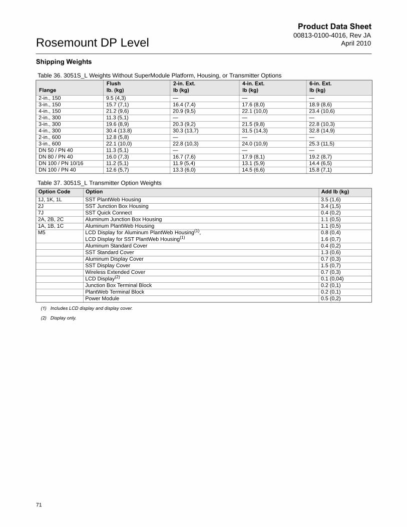
Product Data Sheet00813-0100-4016, Rev JA
April 2010Rosemount DP Level
71
Shipping Weights
Table 36. 3051S_L Weights Without SuperModule Platform, Housing, or Transmitter Options
Table 37. 3051S_L Transmitter Option Weights
FlangeFlushlb. (kg)
2-in. Ext.lb (kg)
4-in. Ext.lb (kg)
6-in. Ext.lb (kg)
2-in., 150 9.5 (4,3) — — —3-in., 150 15.7 (7,1) 16.4 (7,4) 17.6 (8,0) 18.9 (8,6)4-in., 150 21.2 (9,6) 20.9 (9,5) 22.1 (10,0) 23.4 (10,6)2-in., 300 11.3 (5,1) — — —3-in., 300 19.6 (8,9) 20.3 (9,2) 21.5 (9,8) 22.8 (10,3)4-in., 300 30.4 (13.8) 30.3 (13,7) 31.5 (14,3) 32.8 (14,9)2-in., 600 12.8 (5,8) — — —3-in., 600 22.1 (10,0) 22.8 (10,3) 24.0 (10,9) 25.3 (11,5)DN 50 / PN 40 11.3 (5,1) — — —DN 80 / PN 40 16.0 (7,3) 16.7 (7,6) 17.9 (8,1) 19.2 (8,7)DN 100 / PN 10/16 11.2 (5,1) 11.9 (5,4) 13.1 (5,9) 14.4 (6,5)DN 100 / PN 40 12.6 (5,7) 13.3 (6,0) 14.5 (6,6) 15.8 (7,1)
Option Code Option Add lb (kg)1J, 1K, 1L SST PlantWeb Housing 3.5 (1,6)2J SST Junction Box Housing 3.4 (1,5)7J SST Quick Connect 0.4 (0,2)2A, 2B, 2C Aluminum Junction Box Housing 1.1 (0,5)1A, 1B, 1C Aluminum PlantWeb Housing 1.1 (0,5)M5 LCD Display for Aluminum PlantWeb Housing(1),
LCD Display for SST PlantWeb Housing(1)0.8 (0,4)1.6 (0,7)
Aluminum Standard Cover 0.4 (0,2)SST Standard Cover 1.3 (0,6)Aluminum Display Cover 0.7 (0,3)SST Display Cover 1.5 (0,7)Wireless Extended Cover 0.7 (0,3)LCD Display(2) 0.1 (0,04)Junction Box Terminal Block 0.2 (0,1)PlantWeb Terminal Block 0.2 (0,1)Power Module 0.5 (0,2)
(1) Includes LCD display and display cover.
(2) Display only.
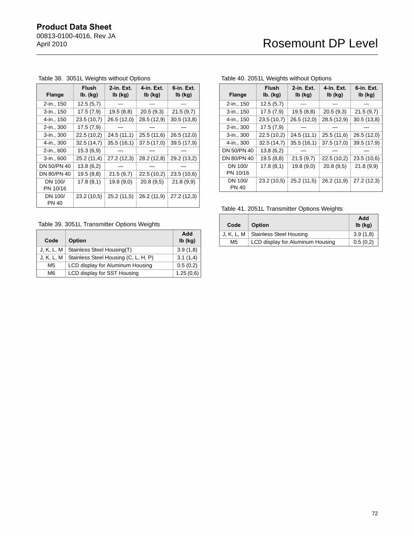
Product Data Sheet00813-0100-4016, Rev JAApril 2010 Rosemount DP Level
72
Table 38. 3051L Weights without Options
FlangeFlush
lb. (kg)2-in. Ext.
lb (kg)4-in. Ext.
lb (kg)6-in. Ext.
lb (kg)2-in., 150 12.5 (5,7) — — —
3-in., 150 17.5 (7,9) 19.5 (8,8) 20.5 (9,3) 21.5 (9,7)
4-in., 150 23.5 (10,7) 26.5 (12,0) 28.5 (12,9) 30.5 (13,8)
2-in., 300 17.5 (7,9) — — —
3-in., 300 22.5 (10,2) 24.5 (11,1) 25.5 (11,6) 26.5 (12,0)
4-in., 300 32.5 (14,7) 35.5 (16,1) 37.5 (17,0) 39.5 (17,9)
2-in., 600 15.3 (6,9) — — —
3-in., 600 25.2 (11,4) 27.2 (12,3) 28.2 (12,8) 29.2 (13,2)
DN 50/PN 40 13.8 (6,2) — — —
DN 80/PN 40 19.5 (8,8) 21.5 (9,7) 22.5 (10,2) 23.5 (10,6)
DN 100/PN 10/16
17.8 (8,1) 19.8 (9,0) 20.8 (9,5) 21.8 (9,9)
DN 100/PN 40
23.2 (10,5) 25.2 (11,5) 26.2 (11,9) 27.2 (12,3)
Table 39. 3051L Transmitter Options Weights
Code OptionAdd
lb (kg)J, K, L, M Stainless Steel Housing(T) 3.9 (1,8)
J, K, L, M Stainless Steel Housing (C, L, H, P) 3.1 (1,4)
M5 LCD display for Aluminum Housing 0.5 (0,2)
M6 LCD display for SST Housing 1.25 (0,6)
Table 40. 2051L Weights without Options
FlangeFlush
lb. (kg)2-in. Ext.
lb (kg)4-in. Ext.
lb (kg)6-in. Ext.
lb (kg)2-in., 150 12.5 (5,7) — — —
3-in., 150 17.5 (7,9) 19.5 (8,8) 20.5 (9,3) 21.5 (9,7)
4-in., 150 23.5 (10,7) 26.5 (12,0) 28.5 (12,9) 30.5 (13,8)
2-in., 300 17.5 (7,9) — — —
3-in., 300 22.5 (10,2) 24.5 (11,1) 25.5 (11,6) 26.5 (12,0)
4-in., 300 32.5 (14,7) 35.5 (16,1) 37.5 (17,0) 39.5 (17,9)
DN 50/PN 40 13.8 (6,2) — — —
DN 80/PN 40 19.5 (8,8) 21.5 (9,7) 22.5 (10,2) 23.5 (10,6)
DN 100/PN 10/16
17.8 (8,1) 19.8 (9,0) 20.8 (9,5) 21.8 (9,9)
DN 100/PN 40
23.2 (10,5) 25.2 (11,5) 26.2 (11,9) 27.2 (12,3)
Table 41. 2051L Transmitter Options Weights
Code OptionAdd
lb (kg)J, K, L, M Stainless Steel Housing 3.9 (1,8)
M5 LCD display for Aluminum Housing 0.5 (0,2)
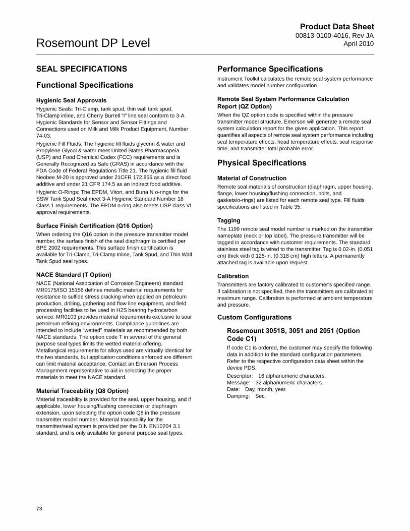
Product Data Sheet00813-0100-4016, Rev JA
April 2010Rosemount DP Level
SEAL SPECIFICATIONS
Functional Specifications
Hygienic Seal ApprovalsHygienic Seals: Tri-Clamp, tank spud, thin wall tank spud, Tri-Clamp inline, and Cherry Burrell “I” line seal conform to 3-A Hygienic Standards for Sensor and Sensor Fittings and Connections used on Milk and Milk Product Equipment, Number 74-03.
Hygienic Fill Fluids: The hygienic fill fluids glycerin & water and Propylene Glycol & water meet United States Pharmacopeia (USP) and Food Chemical Codex (FCC) requirements and is Generally Recognized as Safe (GRAS) in accordance with the FDA Code of Federal Regulations Title 21. The hygienic fill fluid Neobee M-20 is approved under 21CFR 172.856 as a direct food additive and under 21 CFR 174.5 as an indirect food additive.
Hygienic O-Rings: The EPDM, Viton, and Buna N o-rings for the SSW Tank Spud Seal meet 3-A Hygienic Standard Number 18 Class 1 requirements. The EPDM o-ring also meets USP class VI approval requirements.
Surface Finish Certification (Q16 Option)When ordering the Q16 option in the pressure transmitter model number, the surface finish of the seal diaphragm is certified per BPE 2002 requirements. This surface finish certification is available for Tri-Clamp, Tri-Clamp Inline, Tank Spud, and Thin Wall Tank Spud seal types.
NACE Standard (T Option)NACE (National Association of Corrosion Engineers) standard MR0175/ISO 15156 defines metallic material requirements for resistance to sulfide stress cracking when applied on petroleum production, drilling, gathering and flow line equipment, and field processing facilities to be used in H2S bearing hydrocarbon service. MR0103 provides material requirements exclusive to sour petroleum refining environments. Compliance guidelines are intended to include “wetted” materials as recommended by both NACE standards. The option code T in several of the general purpose seal types limits the wetted material offering. Metallurgical requirements for alloys used are virtually identical for the two standards, but application conditions enforced are different can limit material acceptance. Contact an Emerson Process Management representative to aid in selecting the proper materials to meet the NACE standard.
Material Traceability (Q8 Option)Material traceability is provided for the seal, upper housing, and if applicable, lower housing/flushing connection or diaphragm extension, upon selecting the option code Q8 in the pressure transmitter model number. Material traceability for the transmitter/seal system is provided per the DIN EN10204 3.1 standard, and is only available for general purpose seal types.
Performance SpecificationsInstrument Toolkit calculates the remote seal system performance and validates model number configuration.
Remote Seal System Performance Calculation Report (QZ Option)When the QZ option code is specified within the pressure transmitter model structure, Emerson will generate a remote seal system calculation report for the given application. This report quantifies all aspects of remote seal system performance including seal temperature effects, head temperature effects, seal response time, and transmitter total probable error.
Physical Specifications
Material of ConstructionRemote seal materials of construction (diaphragm, upper housing, flange, lower housing/flushing connection, bolts, and gaskets/o-rings) are listed for each remote seal type. Fill fluids specifications are listed in Table 35.
Tagging The 1199 remote seal model number is marked on the transmitter nameplate (neck or top label). The pressure transmitter will be tagged in accordance with customer requirements. The standard stainless steel tag is wired to the transmitter. Tag is 0.02-in. (0.051 cm) thick with 0.125-in. (0.318 cm) high letters. A permanently attached tag is available upon request.
Calibration Transmitters are factory calibrated to customer’s specified range. If calibration is not specified, then the transmitters are calibrated at maximum range. Calibration is performed at ambient temperature and pressure.
Custom Configurations
Rosemount 3051S, 3051 and 2051 (Option Code C1) If code C1 is ordered, the customer may specify the following data in addition to the standard configuration parameters. Refer to the respective configuration data sheet within the device PDS.
Descriptor: 16 alphanumeric characters.Message: 32 alphanumeric characters.Date: Day, month, year.Damping: Sec.
73
Product Data Sheet00813-0100-4016, Rev JAApril 2010 Rosemount DP Level
Rosemount 3051S_L CertificationsApproved Manufacturing LocationsRosemount Inc. — Chanhassen, Minnesota USA
Emerson Process Management GmbH & Co. — Wessling, Germany
Emerson Process Management Asia Pacific Private Limited — Singapore
Beijing Rosemount Far East Instrument Co., LTD — Beijing, China
Emerson Process Management LTDA — Sorocaba, Brazil
Emerson Process Management (India) Pvt. Ltd. — Daman, India
Ordinary Location Certification for FMAs standard, the transmitter has been examined and tested to determine that the design meets basic electrical, mechanical, and fire protection requirements by FM, a nationally recognized testing laboratory (NRTL) as accredited by the Federal Occupational Safety and Health Administration (OSHA).
European Directive InformationThe EC declaration of conformity for all applicable European directives for this product can be found at www.rosemount.com. A hard copy may be obtained by contacting an Emerson Process Management representative.
ATEX Directive (94/9/EC)Emerson Process Management complies with the ATEX Directive.
European Pressure Equipment Directive (PED) (97/23/EC)Models 3051S_CA4; 3051S_CD2, 3, 4, 5; (also with P9 option) Pressure Transmitters — QS Certificate of Assessment - EC No. PED-H-100, Module H Conformity Assessment
All other Model 3051S Pressure Transmitters— Sound Engineering Practice
Transmitter Attachments: Diaphragm Seal - Process Flange - Manifold — Sound Engineering Practice
Primary Elements, Flowmeter— See appropriate Primary Element QIG
Electro Magnetic Compatibility (EMC) (2004/108/EC)EN 61326-1:1997 + A1, A2, and A3 – Industrial
Radio and Telecommunications Terminal Equipment Directive (R&TTE)(1999/5/EC)
Emerson Process Management complies with the R&TTE Directive.
HART & FOUNDATION Fieldbus Hazardous Locations CertificationsNorth American CertificationsFM ApprovalsE5 Explosion-proof for Class I, Division 1, Groups B, C, and D,
T5 (Ta = 85 °C); Dust Ignition-proof for Class II and Class III, Division 1, Groups E, F, and G, T5 (Ta = 85 °C); hazardous locations; enclosure Type 4X, conduit seal not required when installed according to Rosemount drawing 03151-1003.
I5/IE Intrinsically Safe for use in Class I, Division 1, Groups A, B, C, and D, T4 (Ta = 70 °C for output options A or X; Ta = 60 °C for output option F); Class II, Division 1, Groups E, F, and G; Class III, Division 1; Class I, Zone 0 AEx ia IIC T4 (Ta = 70 °C for output options A or X; Ta = 60 °C for output option F) when connected in accordance with Rosemount drawing 03151-1006; Non-Incendive for Class I, Division 2, Groups A, B, C, and D; T4 (Ta = 70 °C for output options A or X; Ta = 60 °C for output option F) Enclosure Type 4X For entity parameters see control drawing 03151-1006.
Canadian Standards Association (CSA) All CSA hazardous approved transmitters are certified per ANSI/ISA 12.27.01-2003.
E6 Explosion-proof for Class I, Division 1, Groups B, C, and D; Dust Ignition-proof for Class II and Class III, Division 1, Groups E, F, and G; suitable for Class I, Division 2, Groups A, B, C, and D, when installed per Rosemount drawing 03151-1013, CSA Enclosure Type 4X; conduit seal not required; Dual Seal.
I6/IF Intrinsically Safe for Class I, Division 1, Groups A, B, C, and D when connected in accordance with Rosemount drawings 03151-1016; Dual Seal.For entity parameters see control drawing 03151-1016.
European CertificationsI1/IA ATEX Intrinsic Safety
Certificate No.: BAS01ATEX1303X II 1GEx ia IIC T4 (Ta = -60 °C to 70 °C) -HART/Remote Display/Quick Connect/HART DiagnosticsEx ia IIC T4 (Ta = -60 °C to 70 °C) -FOUNDATION fieldbusEx ia IIC T4 (Ta = -60 °C to 40 °C) -FISCO
1180
Input ParametersLoop / Power GroupsUi = 30 V HART / FOUNDATION fieldbus/ Remote Display /
Quick Connect / HART DiagnosticsUi = 17.5 V FISCOIi = 300 mA HART / FOUNDATION fieldbus/ Remote Display /
Quick Connect / HART DiagnosticsIi = 380 mA FISCOPi = 1.0 W HART / Remote Display / Quick Connect /
HART DiagnosticsPi = 1.3 W FOUNDATION fieldbusPi = 5.32 W FISCOCi = 30 nF SuperModule PlatformCi = 11.4 nF HART / HART Diagnostics / Quick ConnectCi = 0 FOUNDATION fieldbus / Remote Display / FISCOLi = 0 HART / FOUNDATION fieldbus/ FISCO / Quick
Connect / HART DiagnosticsLi = 60 µH Remote Display
RTD Assembly (3051SFx Option T or R)Ui = 5 VdcIi = 500 mAPi = 0.63W
74
Product Data Sheet00813-0100-4016, Rev JA
April 2010Rosemount DP Level
Special conditions for safe use (x)1. The apparatus, excluding the Types 3051 S-T and 3051
S-C (In-line and Coplanar SuperModule Platforms respectively), is not capable of withstanding the 500V test as defined in Clause 6.3.12 of EN 60079-11. This must be considered during installation.
2. The terminal pins of the Types 3051 S-T and 3051 S-C must be protected to IP20 minimum.
N1 ATEX Type nCertificate No.: BAS01ATEX3304X II 3 GEx nL IIC T5 (Ta = -40 °C TO 70 °C)Ui = 45 Vdc maxCi = 11.4 nFLi = 0For remote display, Ci = 0, Li = 60 μHIP66
Special conditions for safe use (x)The apparatus is not capable of withstanding the 500V insulation test required by Clause 6.8.1 of EN 60079-15.This must be taken into account when installing the apparatus.
NOTERTD Assembly is not included with the 3051SFx Type n Approval.
ND ATEX Dust Certificate No.: BAS01ATEX1374X II 1 DEx tD A20 T105°C (-20 °C Tamb 85 °C)Vmax = 42.4 volts maxA = 22 mAIP66
1180
Special conditions for safe use (x)1. Cable entries must be used which maintain the ingress
protection of the enclosure to at least IP66.2. Unused cable entries must be filled with suitable blanking
plugs which maintain the ingress protection of the enclosure to at least IP66.
3. Cable entries and blanking plugs must be suitable for the ambient range of the apparatus and capable of withstanding a 7J impact test.
4. The 3051S must be securely screwed in place to maintain the ingress protection of the enclosure. (The 3051S SuperModule must be properly assembled to the 3051S housing to maintain ingress protection.)
E1 ATEX Flameproof Certificate No.: KEMA00ATEX2143X II 1/2 GEx d IIC T6 (-50 °C Tamb 65 °C)Ex d IIC T5 (-50 °C Tamb 80 °C)Vmax = 42.4V
1180
Special conditions for safe use (x)
1. Appropriate ex d blanking plugs, cable glands, and wiring needs to be suitable for a temperature of 90 °C.
2. This device contains a thin wall diaphragm. Installation, maintenance and use shall take into account the environmental conditions to which the diaphragm will be subjected. The manufacturer’s instructions for maintenance shall be followed in detail to assure safety during its expected lifetime.
3. The 3051S does not comply with the requirements of EN 60079-1 Clause 5.2, Table 2 for all joints. Contact Emerson Process Management for information on the dimensions of flameproof joints.
Japanese Certifications E4 TIIS Flameproof
Ex d IIC T6
Certificate DescriptionTC15682 Coplanar with Junction Box HousingTC15683 Coplanar with PlantWeb HousingTC15684 Coplanar with PlantWeb Housing
and LCD DisplayTC15685 In-Line SST with Junction Box HousingTC15686 In-Line Alloy C-276 with Junction Box HousingTC15687 In-Line SST with PlantWeb HousingTC15688 In-Line Alloy C-276 with PlantWeb HousingTC15689 In-Line SST with PlantWeb Housing
and LCD DisplayTC15690 In-Line Alloy C-276 with PlantWeb Housing
and LCD DisplayTC17102 Remote DisplayTC17099 3051SFA/C/P SST/Alloy C-276 with
PlantWeb Housing and LCD DisplayTC17100 3051SFA/C/P SST/Alloy C-276 with
PlantWeb Housing and Remote DisplayTC17101 3051SFA/C/P SST/Alloy C-276 with
Junction Box Housing
75
Product Data Sheet00813-0100-4016, Rev JAApril 2010 Rosemount DP Level
China (NEPSI) CertificationsI3 China Intrinsic Safety, Dust Ignition-proof
Certificate No. (manufactured in Chanhassen, MN): GYJ081078 Certificate No. (manufactured in Beijing, China): GYJ06367 Certificate No. (manufactured in Singapore): GYJ06365Certificate No. (3051SFx RTC, BMMC, SMMC): GYJ071293Ex ia IIC T4DIP A21 TA T4 IP66
NOTERefer to Appendix B of the 3051S Reference Manual (document number 00809-0100-4801) for Special Conditions for Safe Use.
E3 China Flameproof, Dust Ignition-proofCertificate No. (manufactured in Chanhassen, MN): GYJ091035Certificate No. (manufactured in Beijing, China): GYJ06366Certificate No. (manufactured in Singapore): GYJ06364Certificate No. (3051SFx RTC, BMMC, SMMC): GYJ071086Ex d IIB+H2 T3~T5DIP A21 TA T3~T5 IP66
NOTERefer to Appendix B of the 3051S Reference Manual (document number 00809-0100-4801) for Special Conditions for Safe Use.
INMETRO Certifications I2 Brazilian Approval (INMETRO Approval) - Intrinsic Safety
Certificate number: CEPEL-EX-0722/05X (manufacturing in Chanhassen, MN and Singapore)Certificate number: CEPEL-EX-1414/07X (manufacturing in Brazil)INMETRO Marking: BR-Ex ia IIC T4 IP66W
Special conditions for safe use (x)The apparatus, excluding the Types 3051S-T and 3051S-C (In-line and Coplanar SuperModule Platforms respectively), is not capable of withstanding the 500V test as defined in Clause 6.3.12 of IEC60079-11. This must be considered during installation.
E2 Brazilian Approval (INMETRO Approval) - FlameproofCertificate number: CEPEL-EX-140/2003X (manufacturing in Chanhassen, MN and Singapore)Certificate number: CEPEL-EX-1413/07X (manufacturing in Brazil)INMETRO Marking: BR-Ex d IIC T5/T6 IP66W
Special conditions for safe use (x)
1. This device contains a thin wall diaphragm. Installation, maintenance,and use shall take into account the environmental conditions to which the diaphragm will be subjected. The manufacturer’s instructions for installation and maintenance shall be followed in detail to assure safety during its expected lifetime.
2. For ambient temperature above 60 ºC, cable wiring must have minimum isolation temperature of 90 ºC, to be in accordance to equipment operation temperature.
3. The accessory of cable entries or conduit must be certified as flameproof and needs to be suitable for use conditions.
4. Where electrical entry is via conduit, the required sealing device must be assembled immediately close to enclosure.
Input ParametersLoop / Power GroupsUi = 30 V HART / FOUNDATION fieldbus/ Remote Display /
Quick Connect / HART DiagnosticsIi = 300 mA HART / FOUNDATION fieldbus/ Remote Display /
Quick Connect / HART DiagnosticsPi = 1.0 W HART / Remote Display / Quick Connect /
HART DiagnosticsPi = 1.3 W FOUNDATION fieldbusCi = 38 nF SuperModule PlatformCi = 11.4 nF HART / HART Diagnostics / Quick ConnectCi = 0 FOUNDATION fieldbus / Remote DisplayLi = 0 HART / FOUNDATION fieldbus / Quick Connect /
HART DiagnosticsLi = 60 µH Remote Display
RTD Assembly (3051SFx Option T or R)Ui = 5 VdcIi = 500 mAPi = 0.63W
76
Product Data Sheet00813-0100-4016, Rev JA
April 2010Rosemount DP Level
IECEx CertificationsE7 IECEx Flameproof and Dust (each listed separately)
IECEx FlameproofCertificate No.: IECExKEM08.0010XEx d IIC T6 (-50 °C Tamb 65 °C)Ex d IIC T5 (-50 °C Tamb 80 °C)Vmax = 42.4V
Special conditions for safe use (x)
1. Appropriate ex d blanking plugs, cable glands, and wiring needs to be suitable for a temperature of 90 °C.
2. This device contains a thin wall diaphragm. Installation, maintenance and use shall take into account the environmental conditions to which the diaphragm will be subjected. The manufacturer’s instructions for maintenance shall be followed in detail to assure safety during its expected lifetime.
3. The 3051S does not comply with the requirements of IEC 60079-1 Clause 5.2, Table 2 for all joints. Contact Emerson Process Management for information on the dimensions of flameproof joints.
IECEx DustCertificate No. IECExBAS09.0014XEx tD A20 T105°C (-20°C ≤ Tamb ≤ 85°C)Vmax = 42.4 VA = 22 mAIP66Special conditions for safe use (x)
1. Cable entries must be used which maintain the ingress protection of the enclosure to at least IP66.
2. Unused cable entries must be filled with suitable blanking plugs which maintain the ingress protection of the enclosure to at least IP66.
3. Cable entries and blanking plugs must be suitable for the ambient range of the apparatus and capable of withstanding a 7J impact test.
4. The 3051S must be securely screwed in place to maintain the ingress protection of the enclosure. (The 3051S SuperModule must be properly assembled to the 3051S housing to maintain ingress protection.)
I7/IG IECEx Intrinsic SafetyCertificate No.: IECExBAS04.0017XEx ia IIC T4 (Ta = -60 °C to 70 °C) -HART/Remote Display/Quick Connect/HART Diagnostics Ex ia IIC T4 (Ta = -60 °C to 70 °C) -FOUNDATION fieldbusEx ia IIC T4 (Ta = -60 °C to 40 °C) -FISCOIP66
Special conditions for safe use (x)1. The 3051S HART 4-20 mA, 3051S FOUNDATION fieldbus,
3051S Profibus and 3051S FISCO are not capable of withstanding the 500V test as defined in clause 6.3.12 of IEC 60079-11. This must be taken into account during installation.
2. The terminal pins of the Types 3051S-T and 3051S-C must be protected to IP20 minimum.
N7 IECEx Type nCertificate No.: IECExBAS04.0018XEx nC IIC T4 (Ta = -40 °C to 70 °C)Ui = 45 Vdc MAXIP66Special conditions for safe use (x)The apparatus is not capable of withstanding the 500 V insulation test required by Clause 8 of IEC 60079-15.
Input ParametersLoop / Power GroupsUi = 30 V HART / FOUNDATION fieldbus/ Remote
Display / Quick Connect / HART Diagnostics
Ui = 17.5 V FISCOIi = 300 mA HART / FOUNDATION fieldbus/ Remote
Display / Quick Connect / HART Diagnostics
Ii = 380 mA FISCOPi = 1.0 W HART / Remote Display / Quick
Connect / HART DiagnosticsPi = 1.3 W FOUNDATION fieldbusPi = 5.32 W FISCOCi = 30 nF SuperModule PlatformCi = 11.4 nF HART / HART Diagnostics / Quick
ConnectCi = 0 FOUNDATION fieldbus / Remote Display /
FISCOLi = 0 HART / FOUNDATION fieldbus/ FISCO /
Quick Connect / HART DiagnosticsLi = 60 H Remote Display
RTD Assembly (3051SFx Option T or R)Ui = 5 VdcIi = 500 mAPi = 0.63 W
77
Product Data Sheet00813-0100-4016, Rev JAApril 2010 Rosemount DP Level
Combinations of CertificationsStainless steel certification tag is provided when optional approval is specified. Once a device labeled with multiple approval types is installed, it should not be reinstalled using any other approval types. Permanently mark the approval label to distinguish it from unused approval types.
K1 Combination of E1, I1, N1, and ND
K2 Combination of E2 and I2
K5 Combination of E5 and I5
K6 Combination of E6 and I6
K7 Combination of E7, I7, and N7
KA Combination of E1, I1, E6, and I6
KB Combination of E5, I5, I6 and E6
KC Combination of E5, E1, I5 and I1
KD Combination of E5, I5, E6, I6, E1, and I1
78
Product Data Sheet00813-0100-4016, Rev JA
April 2010Rosemount DP Level
3051L Product CertificationsApproved Manufacturing LocationsRosemount Inc. — Chanhassen, Minnesota USAEmerson Process Management GmbH & Co. — Wessling, GermanyEmerson Process Management Asia Pacific Private Limited — SingaporeBeijing Rosemount Far East Instrument Co., LTD — Beijing, China
European Directive InformationThe EC declaration of conformity for all applicable European directives for this product can be found on the Rosemount website at www.rosemount.com. A hard copy may be obtained by contacting an Emerson Process Management representative.
ATEX Directive (94/9/EC)All 3051 transmitters comply with the ATEX Directive.
European Pressure Equipment Directive (PED) (97/23/EC)3051CA4; 3051CG2, 3, 4, 5; 3051CD2, 3, 4, 5 (also with P9 option); 3051HD2, 3, 4, 5; 3051HG2, 3, 4, 5; 3051PD2, 3; and 3051PG2, 3, 4, 5 Pressure Transmitters — QS Certificate of Assessment - EC No. PED-H-100
Module H Conformity Assessment
All other 3051/3001 Pressure Transmitters— Sound Engineering Practice
Transmitter Attachments: Diaphragm Seal - Process Flange - Manifold
— Sound Engineering Practice
Electro Magnetic Compatibility (EMC) (2004/108/EC)All 3051 Pressure Transmitters meet all of the requirements of EN61326: 1997 - A1, A2, and A3 and NAMUR NE-21
Ordinary Location Certification for Factory MutualAs standard, the transmitter has been examined and tested to determine that the design meets basic electrical, mechanical, and fire protection requirements by FM, a nationally recognized testing laboratory (NRTL) as accredited by the Federal Occupational Safety and Health Administration (OSHA).
HART PROTOCOL
Hazardous Locations CertificationsNorth American Certifications
FM Approvals
E5 Explosion-Proof for Class I, Division 1, Groups B, C, and D. Dust-Ignition-Proof for Class II, Division 1, Groups E, F, and G. Dust-Ignition-Proof for Class III, Division 1. Factory Sealed, Enclosure Type 4X
I5 Intrinsically Safe for use in Class I, Division 1, Groups A, B, C, and D; Class II, Division 1, Groups E, F, and G; Class III, Division 1 when connected per Rosemount drawing 03031-1019; Non-incendive for Class I, Division 2, Groups A, B, C, and D.Temperature Code:T4 (Ta = 40 °C), T3 (Ta = 85 °C), Enclosure Type 4XFor input parameters see control drawing 03031-1019.
Canadian Standards Association (CSA)All CSA hazardous approved transmitters are certified per ANSI/ISA 12.27.01-2003.
E6 Explosion-Proof for Class I, Division 1, Groups B, C, and D. Dust-Ignition-Proof for Class II and Class III, Division 1, Groups E, F, and G. Suitable for Class I, Division 2 Groups A, B, C, and D for indoor and outdoor hazardous locations. Enclosure type 4X, factory sealed
C6 Explosion-Proof and intrinsically safe approval. Intrinsically safe for Class I, Division 1, Groups A, B, C, and D when connected in accordance with Rosemount drawings 03031-1024. Temperature Code T3C.Explosion-Proof for Class I, Division 1, Groups B, C, and D. Dust-Ignition-Proof for Class II and Class III, Division 1, Groups E, F, and G. Suitable for Class I, Division 2 Groups A, B, C, and D hazardous locations. Enclosure type 4X, factory sealedFor input parameters see control drawing 03031-1024.
79
Product Data Sheet00813-0100-4016, Rev JAApril 2010 Rosemount DP Level
European CertificationsI1 ATEX Intrinsic Safety and Dust
Certification No.: BAS 97ATEX1089X II 1 GD Ex ia IIC T4 (–60 Ta +70 °C)Dust Rating: Ex tD A20 T80 °C (–20 Ta 40 °C) IP66
1180
Special Conditions for Safe Use (X): When the optional transient protection terminal block is installed, the apparatus is not capable of withstanding the 500V insulation test required by Clause 6.3.12 of EN60079-11. This must be taken into account when installing the apparatus.The enclosure may be made of aluminium alloy and given a protective polyurethane paint finish; however, care should be taken to protect it from impact or abrasion if located in Zone 0.
N1 ATEX Type n and Dust Certification No.: BAS 00ATEX3105X II 3 GD Ui = 55 Vdc maxEx nA nL T5 (–40°C Tamb 70 °C)Dust rating: Ex tD A22 T80 °C (–20 Ta 40 °C) IP66
Special Conditions for Safe Use (X): When the optional transient protection terminal block is installed, the apparatus is not capable of withstanding a 500V r.m.s. test to case. This must be taken into account on any installation in which it is used, for example, by assuring that the supply to the apparatus is galvanically isolated.
E8 ATEX Flame-Proof and Dust Certification No.: KEMA 00ATEX2013X II 1/2 GD Ex d IIC T6 (–50 Ta 65 °C)
T5 (–50 Ta 80 °C)Dust rating: Ex tD A20/A21 T90 °C, IP66
1180Vmax = 55 V dc
Special Conditions for Safe Use (X): This device contains a thin wall diaphragm. Installation, maintenance, and use shall take into account the environmental conditions to which the diaphragm will be subjected. The manufacturer’s instructions for installation and maintenance shall be followed in detail to assure safety during its expected lifetime.In case of repair, contact Rosemount for dimensions of the flameproof joints.
Japanese CertificationsE4 TIIS Flame-Proof
Ex d IIC T6
Australian CertificationsI7 SAA Intrinsic Safety
Certification No.: AUS Ex 1249XEx ia IIC T4 (Tamb = 70 °C)IP66When connected per Rosemount drawing 03031-1026
Special Conditions for Safe Use (X): The apparatus may only be used with a passive current limited power source Intrinsic Safety application. The power source must be such that Po (Uo * Io) / 4. Modules using transient protection in the terminal assembly (T1 transient protection models) with the apparatus enclosure is to be electrically bonded to the protective earth. The conductor used for the connection shall be equivalent to a copper conductor of 4 mm2, minimum cross-sectional area.
E7 SAA Explosion-Proof (Flame-Proof) Certification No.: AUS Ex 03.1347XEx d IIC T6 (Tamb = 40 °C)
T5 (Tamb = 80 °C) DIP A21 T6 (Tamb = 40 °C)
T5 (Tamb = 80°C) IP66
Special Conditions for Safe Use (X): It is a condition of safe use for transmitter enclosures having cable entry thread other than metric conduit thread that the equipment be utilized with an appropriate certified thread adaptor.
TABLE 42. Input Parameters
Ui = 30V
Ii = 200 mA
Pi = 0.9W
Ci = 0.012 µF
TABLE 43. RTD Assembly (3051CFx Option T or R)
Ui = 5 Vdc
Ii = 500 mA
Pi = 0.63W
Certificate DescriptionC15850 3051C/D/1 4–20 mA HART
— no display
C15851 3051C/D/1 4–20 mA HART — with display
TABLE 44. Input Parameters
Ui = 30V
Ii = 200 mA
Ii = 160 mA (output code A with T1)
Pi = 0.9W
Ci = 0.01 µF
Ci = 0.042 µF (output code M)
Li = 10 µH
Li = 1.05 mH (output code A with T1)
Li = 0.75 mH (output code M with T1)
TABLE 45. RTD Assembly (3051CFx Option T or R)
Ui = 5 Vdc
Ii = 500 mA
Pi = 0.63W
80
Product Data Sheet00813-0100-4016, Rev JA
April 2010Rosemount DP Level
81
N7 SAA Type n (Non-sparking) Certification No.: AUS Ex 1249XEx n IIC T4 (Tamb = 70 °C)IP66
Special Conditions for Safe Use (X): Where the equipment is installed such that there is an unused conduit entry, it must be sealed with a suitable blanking plug to maintain the IP66 degree of protection. Any blanking plug used with the equipment shall be of a type which requires the use of a tool to effect its removal. Voltage source shall not exceed 55V dc.
Combinations of CertificationsStainless steel certification tag is provided when optional approval is specified. Once a device labeled with multiple approval types is installed, it should not be reinstalled using any other approval types. Permanently mark the approval label to distinguish it from unused approval types.
K5 E5 and I5 combination
KB K5 and C6 combination
KD K5, C6, I1, and E8 combination
K6 C6, I1, and E8 combination
K8 E8 and I1 combination
K7 E7, I7, and N7 combination
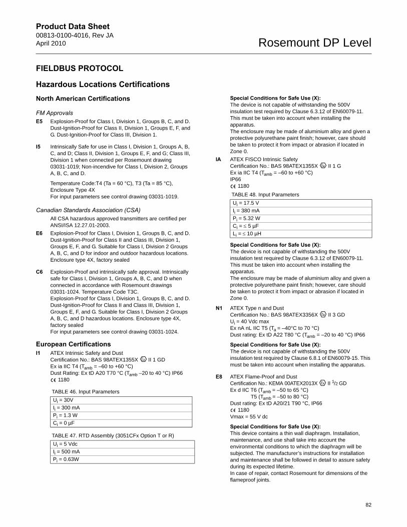
Product Data Sheet00813-0100-4016, Rev JAApril 2010 Rosemount DP Level
82
FIELDBUS PROTOCOL
Hazardous Locations CertificationsNorth American Certifications
FM ApprovalsE5 Explosion-Proof for Class I, Division 1, Groups B, C, and D.
Dust-Ignition-Proof for Class II, Division 1, Groups E, F, and G. Dust-Ignition-Proof for Class III, Division 1.
I5 Intrinsically Safe for use in Class I, Division 1, Groups A, B, C, and D; Class II, Division 1, Groups E, F, and G; Class III, Division 1 when connected per Rosemount drawing 03031-1019; Non-incendive for Class I, Division 2, Groups A, B, C, and D.
Temperature Code:T4 (Ta = 60 °C), T3 (Ta = 85 °C), Enclosure Type 4XFor input parameters see control drawing 03031-1019.
Canadian Standards Association (CSA)All CSA hazardous approved transmitters are certified per ANSI/ISA 12.27.01-2003.
E6 Explosion-Proof for Class I, Division 1, Groups B, C, and D. Dust-Ignition-Proof for Class II and Class III, Division 1, Groups E, F, and G. Suitable for Class I, Division 2 Groups A, B, C, and D for indoor and outdoor hazardous locations. Enclosure type 4X, factory sealed
C6 Explosion-Proof and intrinsically safe approval. Intrinsically safe for Class I, Division 1, Groups A, B, C, and D when connected in accordance with Rosemount drawings 03031-1024. Temperature Code T3C.Explosion-Proof for Class I, Division 1, Groups B, C, and D. Dust-Ignition-Proof for Class II and Class III, Division 1, Groups E, F, and G. Suitable for Class I, Division 2 Groups A, B, C, and D hazardous locations. Enclosure type 4X, factory sealedFor input parameters see control drawing 03031-1024.
European CertificationsI1 ATEX Intrinsic Safety and Dust
Certification No.: BAS 98ATEX1355X II 1 GD Ex ia IIC T4 (Tamb = –60 to +60 °C)Dust Rating: Ex tD A20 T70 °C (Tamb –20 to 40 °C) IP66
1180
Special Conditions for Safe Use (X): The device is not capable of withstanding the 500V insulation test required by Clause 6.3.12 of EN60079-11. This must be taken into account when installing the apparatus.The enclosure may be made of aluminium alloy and given a protective polyurethane paint finish; however, care should be taken to protect it from impact or abrasion if located in Zone 0.
IA ATEX FISCO Intrinsic Safety Certification No.: BAS 98ATEX1355X II 1 G Ex ia IIC T4 (Tamb = –60 to +60 °C)IP66
1180
Special Conditions for Safe Use (X): The device is not capable of withstanding the 500V insulation test required by Clause 6.3.12 of EN60079-11. This must be taken into account when installing the apparatus.The enclosure may be made of aluminium alloy and given a protective polyurethane paint finish; however, care should be taken to protect it from impact or abrasion if located in Zone 0.
N1 ATEX Type n and Dust Certification No.: BAS 98ATEX3356X II 3 GD Ui = 40 Vdc maxEx nA nL IIC T5 (Ta = –40°C to 70 °C)Dust rating: Ex tD A22 T80 °C (Tamb = –20 to 40 °C) IP66
Special Conditions for Safe Use (X): The device is not capable of withstanding the 500V insulation test required by Clause 6.8.1 of EN60079-15. This must be taken into account when installing the apparatus.
E8 ATEX Flame-Proof and Dust Certification No.: KEMA 00ATEX2013X II 1/2 GD Ex d IIC T6 (Tamb = –50 to 65 °C)
T5 (Tamb = –50 to 80 °C)Dust rating: Ex tD A20/21 T90 °C, IP66
1180Vmax = 55 V dc
Special Conditions for Safe Use (X): This device contains a thin wall diaphragm. Installation, maintenance, and use shall take into account the environmental conditions to which the diaphragm will be subjected. The manufacturer’s instructions for installation and maintenance shall be followed in detail to assure safety during its expected lifetime.In case of repair, contact Rosemount for dimensions of the flameproof joints.
TABLE 46. Input Parameters
Ui = 30V
Ii = 300 mA
Pi = 1.3 W
Ci = 0 µF
TABLE 47. RTD Assembly (3051CFx Option T or R)
Ui = 5 Vdc
Ii = 500 mA
Pi = 0.63W
TABLE 48. Input Parameters
Ui = 17.5 V
Ii = 380 mA
Pi = 5.32 W
Ci = 5 µF
Li = 10 µH
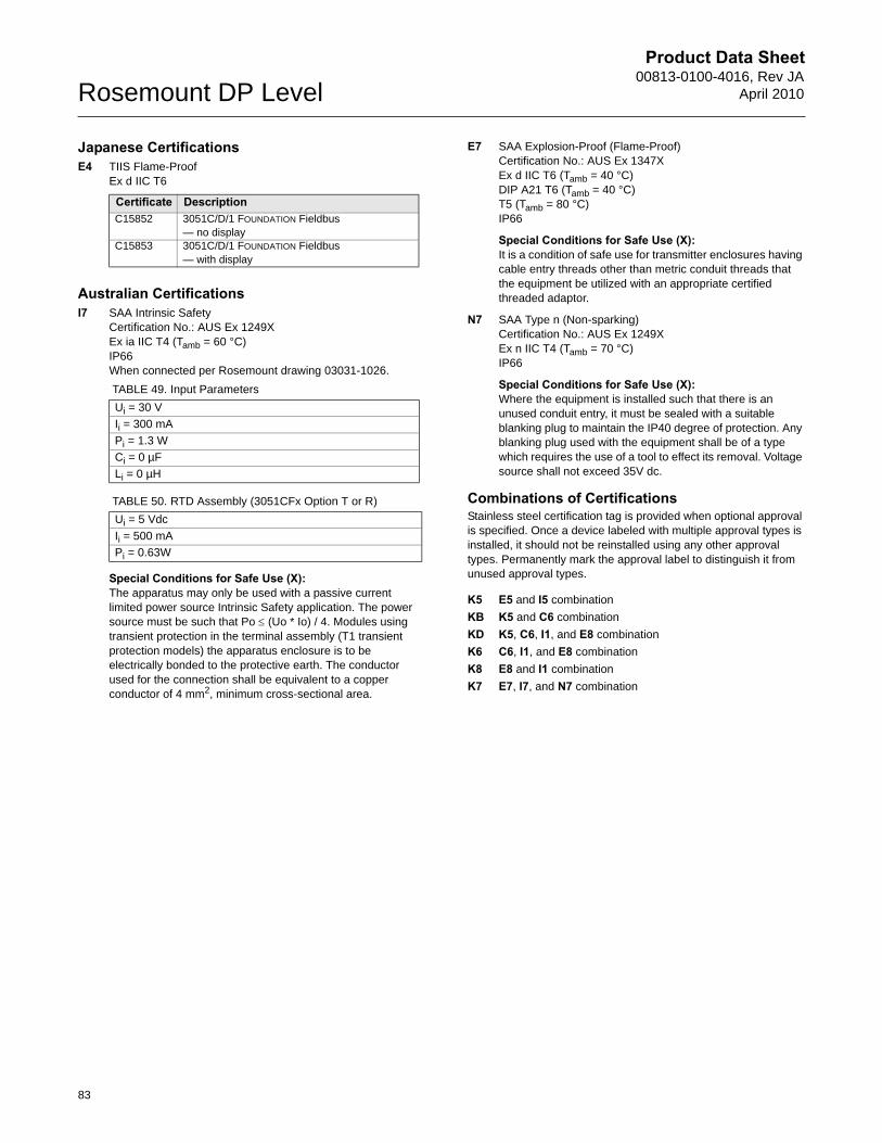
Product Data Sheet00813-0100-4016, Rev JA
April 2010Rosemount DP Level
Japanese CertificationsE4 TIIS Flame-Proof
Ex d IIC T6
Australian CertificationsI7 SAA Intrinsic Safety
Certification No.: AUS Ex 1249XEx ia IIC T4 (Tamb = 60 °C)IP66When connected per Rosemount drawing 03031-1026.
Special Conditions for Safe Use (X): The apparatus may only be used with a passive current limited power source Intrinsic Safety application. The power source must be such that Po (Uo * Io) / 4. Modules using transient protection in the terminal assembly (T1 transient protection models) the apparatus enclosure is to be electrically bonded to the protective earth. The conductor used for the connection shall be equivalent to a copper conductor of 4 mm2, minimum cross-sectional area.
E7 SAA Explosion-Proof (Flame-Proof) Certification No.: AUS Ex 1347XEx d IIC T6 (Tamb = 40 °C) DIP A21 T6 (Tamb = 40 °C)T5 (Tamb = 80 °C)IP66
Special Conditions for Safe Use (X): It is a condition of safe use for transmitter enclosures having cable entry threads other than metric conduit threads that the equipment be utilized with an appropriate certified threaded adaptor.
N7 SAA Type n (Non-sparking) Certification No.: AUS Ex 1249XEx n IIC T4 (Tamb = 70 °C)IP66
Special Conditions for Safe Use (X): Where the equipment is installed such that there is an unused conduit entry, it must be sealed with a suitable blanking plug to maintain the IP40 degree of protection. Any blanking plug used with the equipment shall be of a type which requires the use of a tool to effect its removal. Voltage source shall not exceed 35V dc.
Combinations of CertificationsStainless steel certification tag is provided when optional approval is specified. Once a device labeled with multiple approval types is installed, it should not be reinstalled using any other approval types. Permanently mark the approval label to distinguish it from unused approval types.
K5 E5 and I5 combination
KB K5 and C6 combination
KD K5, C6, I1, and E8 combination
K6 C6, I1, and E8 combination
K8 E8 and I1 combination
K7 E7, I7, and N7 combination
Certificate DescriptionC15852 3051C/D/1 FOUNDATION Fieldbus
— no displayC15853 3051C/D/1 FOUNDATION Fieldbus
— with display
TABLE 49. Input Parameters
Ui = 30 V
Ii = 300 mA
Pi = 1.3 W
Ci = 0 µF
Li = 0 µH
TABLE 50. RTD Assembly (3051CFx Option T or R)
Ui = 5 Vdc
Ii = 500 mA
Pi = 0.63W
83
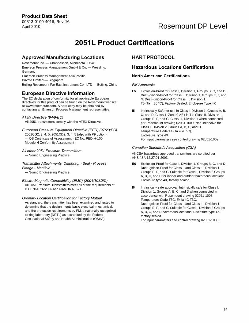
Product Data Sheet00813-0100-4016, Rev JAApril 2010 Rosemount DP Level
2051L Product Certifications
Approved Manufacturing LocationsRosemount Inc. — Chanhassen, Minnesota USAEmerson Process Management GmbH & Co. — Wessling, GermanyEmerson Process Management Asia Pacific Private Limited — SingaporeBeijing Rosemount Far East Instrument Co., LTD — Beijing, China
European Directive InformationThe EC declaration of conformity for all applicable European directives for this product can be found on the Rosemount website at www.rosemount.com. A hard copy may be obtained by contacting an Emerson Process Management representative.
ATEX Directive (94/9/EC)All 2051 transmitters comply with the ATEX Directive.
European Pressure Equipment Directive (PED) (97/23/EC)2051CG2, 3, 4, 5; 2051CD2, 3, 4, 5 (also with P9 option) — QS Certificate of Assessment - EC No. PED-H-100Module H Conformity Assessment
All other 2051 Pressure Transmitters— Sound Engineering Practice
Transmitter Attachments: Diaphragm Seal - Process Flange - Manifold
— Sound Engineering Practice
Electro Magnetic Compatibility (EMC) (2004/108/EC)All 2051 Pressure Transmitters meet all of the requirements of IECEN61326:2006 and NAMUR NE-21.
Ordinary Location Certification for Factory MutualAs standard, the transmitter has been examined and tested to determine that the design meets basic electrical, mechanical, and fire protection requirements by FM, a nationally recognized testing laboratory (NRTL) as accredited by the Federal Occupational Safety and Health Administration (OSHA).
HART PROTOCOL
Hazardous Locations CertificationsNorth American Certifications
FM Approvals
E5 Explosion-Proof for Class I, Division 1, Groups B, C, and D. Dust-Ignition-Proof for Class II, Division 1, Groups E, F, and G. Dust-Ignition-Proof for Class III, Division 1. T5 (Ta = 85 °C), Factory Sealed, Enclosure Type 4X
I5 Intrinsically Safe for use in Class I, Division 1, Groups A, B, C, and D; Class 1, Zone 0 AEx ia T4; Class II, Division 1, Groups E, F, and G; Class III, Division 1 when connected per Rosemount drawing 02051-1009; Non-incendive for Class I, Division 2, Groups A, B, C, and D.Temperature Code:T4 (Ta = 70 °C), Enclosure Type 4XFor input parameters see control drawing 02051-1009.
Canadian Standards Association (CSA)All CSA hazardous approved transmitters are certified per ANSI/ISA 12.27.01-2003.
E6 Explosion-Proof for Class I, Division 1, Groups B, C, and D. Dust-Ignition-Proof for Class II and Class III, Division 1, Groups E, F, and G. Suitable for Class I, Division 2 Groups A, B, C, and D for indoor and outdoor hazardous locations. Enclosure type 4X, factory sealed
I6 Intrinsically safe approval. Intrinsically safe for Class I, Division 1, Groups A, B, C, and D when connected in accordance with Rosemount drawing 02051-1008. Temperature Code T3C; Ex ia IIC T3C.Dust-Ignition-Proof for Class II and Class III, Division 1, Groups E, F, and G. Suitable for Class I, Division 2 Groups A, B, C, and D hazardous locations. Enclosure type 4X, factory sealedFor input parameters see control drawing 02051-1008.
84
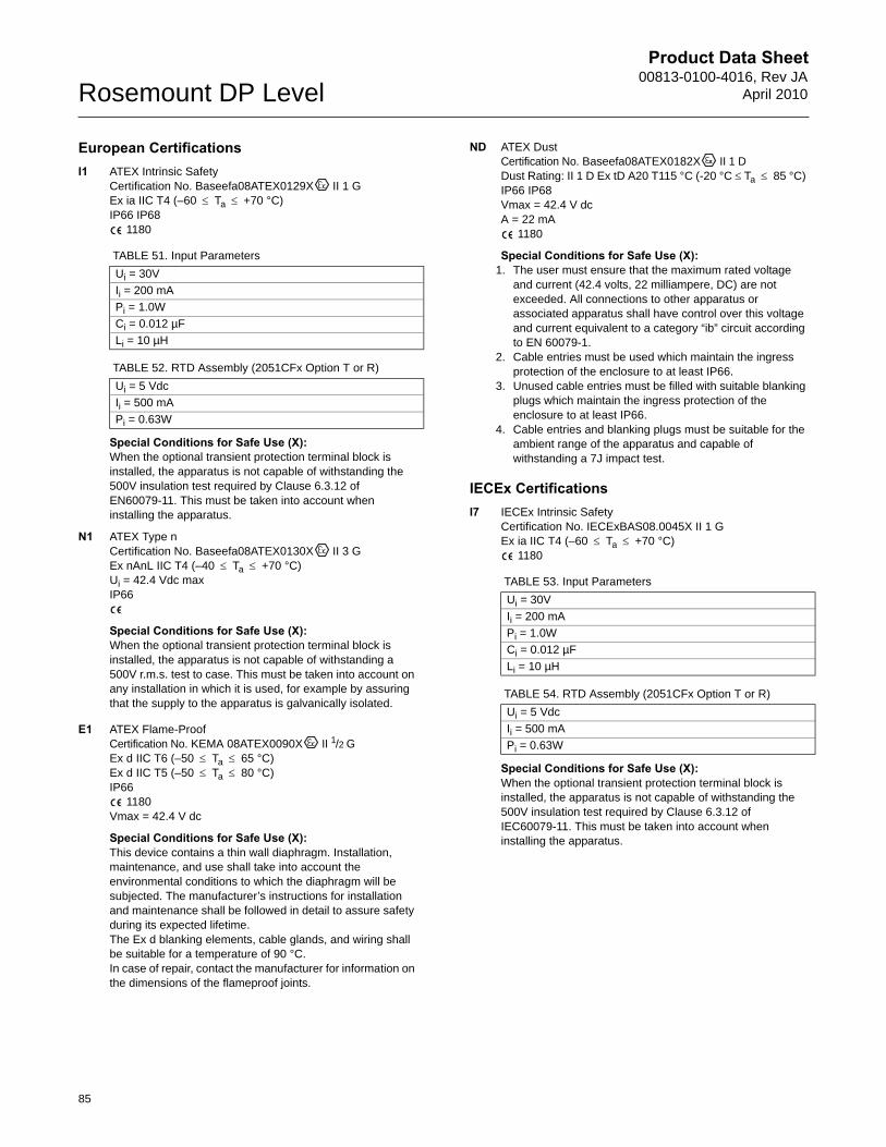
Product Data Sheet00813-0100-4016, Rev JA
April 2010Rosemount DP Level
85
European CertificationsI1 ATEX Intrinsic Safety
Certification No. Baseefa08ATEX0129X II 1 G Ex ia IIC T4 (–60 Ta +70 °C)IP66 IP68
1180
Special Conditions for Safe Use (X): When the optional transient protection terminal block is installed, the apparatus is not capable of withstanding the 500V insulation test required by Clause 6.3.12 of EN60079-11. This must be taken into account when installing the apparatus.
N1 ATEX Type nCertification No. Baseefa08ATEX0130X II 3 GEx nAnL IIC T4 (–40 Ta +70 °C)Ui = 42.4 Vdc maxIP66
Special Conditions for Safe Use (X): When the optional transient protection terminal block is installed, the apparatus is not capable of withstanding a 500V r.m.s. test to case. This must be taken into account on any installation in which it is used, for example by assuring that the supply to the apparatus is galvanically isolated.
E1 ATEX Flame-ProofCertification No. KEMA 08ATEX0090X II 1/2 G Ex d IIC T6 (–50 Ta 65 °C)Ex d IIC T5 (–50 Ta 80 °C)IP66
1180Vmax = 42.4 V dc
Special Conditions for Safe Use (X): This device contains a thin wall diaphragm. Installation, maintenance, and use shall take into account the environmental conditions to which the diaphragm will be subjected. The manufacturer’s instructions for installation and maintenance shall be followed in detail to assure safety during its expected lifetime.The Ex d blanking elements, cable glands, and wiring shall be suitable for a temperature of 90 °C.In case of repair, contact the manufacturer for information on the dimensions of the flameproof joints.
ND ATEX DustCertification No. Baseefa08ATEX0182X II 1 D Dust Rating: II 1 D Ex tD A20 T115 °C (-20 °C Ta 85 °C) IP66 IP68Vmax = 42.4 V dcA = 22 mA
1180
Special Conditions for Safe Use (X): 1. The user must ensure that the maximum rated voltage
and current (42.4 volts, 22 milliampere, DC) are not exceeded. All connections to other apparatus or associated apparatus shall have control over this voltage and current equivalent to a category “ib” circuit according to EN 60079-1.
2. Cable entries must be used which maintain the ingress protection of the enclosure to at least IP66.
3. Unused cable entries must be filled with suitable blanking plugs which maintain the ingress protection of the enclosure to at least IP66.
4. Cable entries and blanking plugs must be suitable for the ambient range of the apparatus and capable of withstanding a 7J impact test.
IECEx CertificationsI7 IECEx Intrinsic Safety
Certification No. IECExBAS08.0045X II 1 G Ex ia IIC T4 (–60 Ta +70 °C)
1180
Special Conditions for Safe Use (X): When the optional transient protection terminal block is installed, the apparatus is not capable of withstanding the 500V insulation test required by Clause 6.3.12 of IEC60079-11. This must be taken into account when installing the apparatus.
TABLE 51. Input Parameters
Ui = 30V
Ii = 200 mA
Pi = 1.0W
Ci = 0.012 µF
Li = 10 µH
TABLE 52. RTD Assembly (2051CFx Option T or R)
Ui = 5 Vdc
Ii = 500 mA
Pi = 0.63W
TABLE 53. Input Parameters
Ui = 30V
Ii = 200 mA
Pi = 1.0W
Ci = 0.012 µF
Li = 10 µH
TABLE 54. RTD Assembly (2051CFx Option T or R)
Ui = 5 Vdc
Ii = 500 mA
Pi = 0.63W
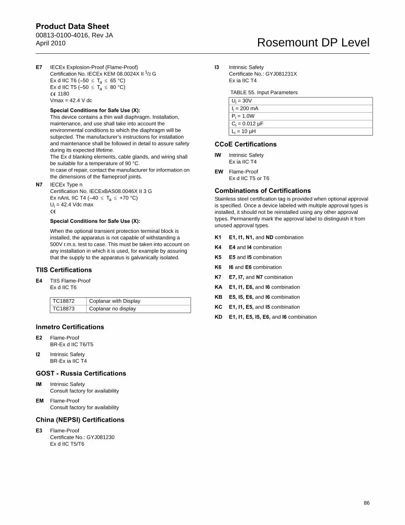
Product Data Sheet00813-0100-4016, Rev JAApril 2010 Rosemount DP Level
86
E7 IECEx Explosion-Proof (Flame-Proof) Certification No. IECEx KEM 08.0024X II 1/2 G Ex d IIC T6 (–50 Ta 65 °C)Ex d IIC T5 (–50 Ta 80 °C)
1180Vmax = 42.4 V dc
Special Conditions for Safe Use (X): This device contains a thin wall diaphragm. Installation, maintenance, and use shall take into account the environmental conditions to which the diaphragm will be subjected. The manufacturer’s instructions for installation and maintenance shall be followed in detail to assure safety during its expected lifetime.The Ex d blanking elements, cable glands, and wiring shall be suitable for a temperature of 90 °C.In case of repair, contact the manufacturer for information on the dimensions of the flameproof joints.
N7 IECEx Type nCertification No. IECExBAS08.0046X II 3 G Ex nAnL IIC T4 (–40 Ta +70 °C)Ui = 42.4 Vdc max
Special Conditions for Safe Use (X):
When the optional transient protection terminal block is installed, the apparatus is not capable of withstanding a 500V r.m.s. test to case. This must be taken into account on any installation in which it is used, for example by assuring that the supply to the apparatus is galvanically isolated.
TIIS Certifications E4 TIIS Flame-Proof
Ex d IIC T6
Inmetro Certifications E2 Flame-Proof
BR-Ex d IIC T6/T5
I2 Intrinsic SafetyBR-Ex ia IIC T4
GOST - Russia CertificationsIM Intrinsic Safety
Consult factory for availability
EM Flame-ProofConsult factory for availability
China (NEPSI) CertificationsE3 Flame-Proof
Certificate No.: GYJ081230Ex d IIC T5/T6
I3 Intrinsic SafetyCertificate No.: GYJ081231XEx ia IIC T4
CCoE CertificationsIW Intrinsic Safety
Ex ia IIC T4
EW Flame-ProofEx d IIC T5 or T6
Combinations of CertificationsStainless steel certification tag is provided when optional approval is specified. Once a device labeled with multiple approval types is installed, it should not be reinstalled using any other approval types. Permanently mark the approval label to distinguish it from unused approval types.
K1 E1, I1, N1, and ND combination
K4 E4 and I4 combination
K5 E5 and I5 combination
K6 I6 and E6 combination
K7 E7, I7, and N7 combination
KA E1, I1, E6, and I6 combination
KB E5, I5, E6, and I6 combination
KC E1, I1, E5, and I5 combination
KD E1, I1, E5, I5, E6, and I6 combination
TC18872 Coplanar with Display
TC18873 Coplanar no display
TABLE 55. Input Parameters
Ui = 30V
Ii = 200 mA
Pi = 1.0W
Ci = 0.012 µF
Li = 10 µH
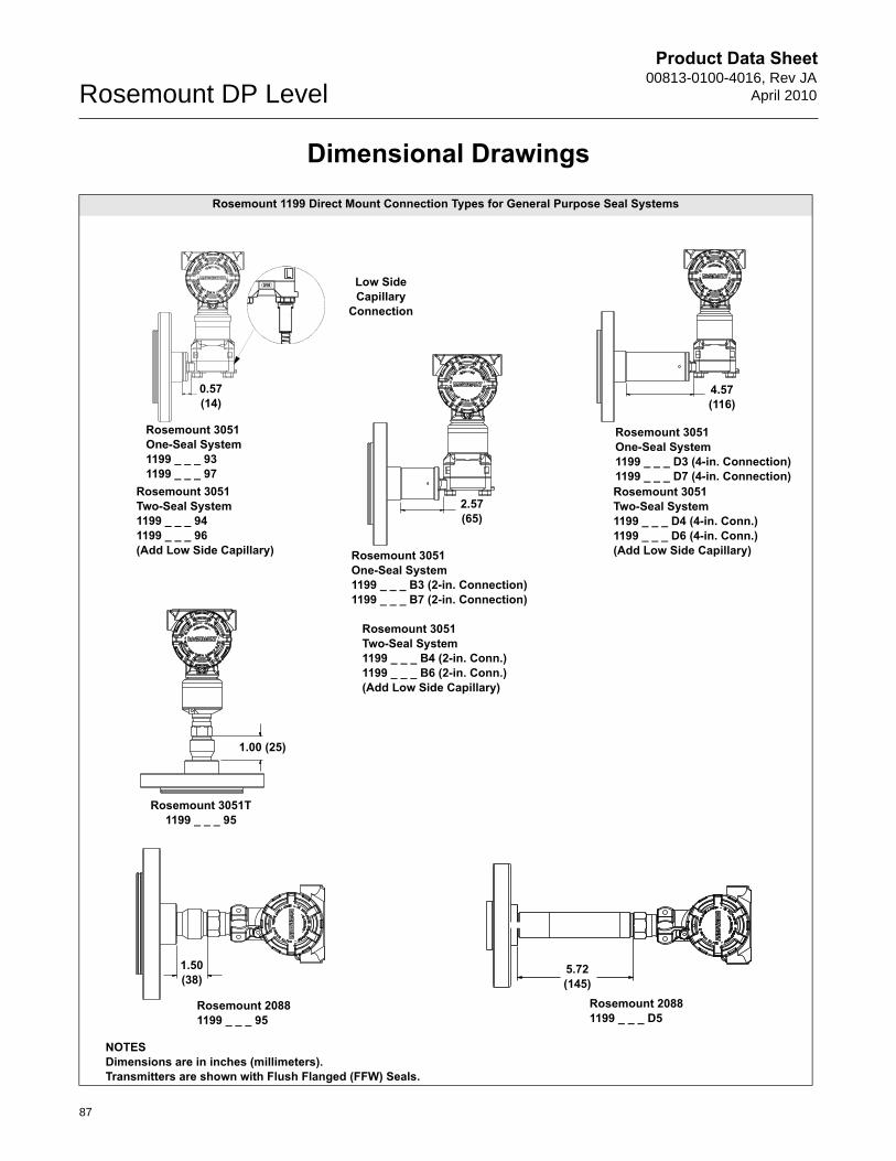
Product Data Sheet00813-0100-4016, Rev JA
April 2010Rosemount DP Level
Dimensional DrawingsRosemount 1199 Direct Mount Connection Types for General Purpose Seal Systems
2.57(65)
Rosemount 3051Two-Seal System1199 _ _ _ 94 1199 _ _ _ 96(Add Low Side Capillary)
Rosemount 20881199 _ _ _ 95
Rosemount 3051One-Seal System1199 _ _ _ 93 1199 _ _ _ 97
Rosemount 3051T1199 _ _ _ 95
1.00 (25)
Rosemount 3051One-Seal System1199 _ _ _ D3 (4-in. Connection)1199 _ _ _ D7 (4-in. Connection)Rosemount 3051Two-Seal System1199 _ _ _ D4 (4-in. Conn.)1199 _ _ _ D6 (4-in. Conn.)(Add Low Side Capillary)Rosemount 3051
One-Seal System1199 _ _ _ B3 (2-in. Connection)1199 _ _ _ B7 (2-in. Connection)
Rosemount 3051Two-Seal System1199 _ _ _ B4 (2-in. Conn.)1199 _ _ _ B6 (2-in. Conn.)(Add Low Side Capillary)
4.57(116)
1.50(38)
Low Side Capillary
Connection
NOTESDimensions are in inches (millimeters). Transmitters are shown with Flush Flanged (FFW) Seals.
0.57(14)
5.72(145)
Rosemount 20881199 _ _ _ D5
87
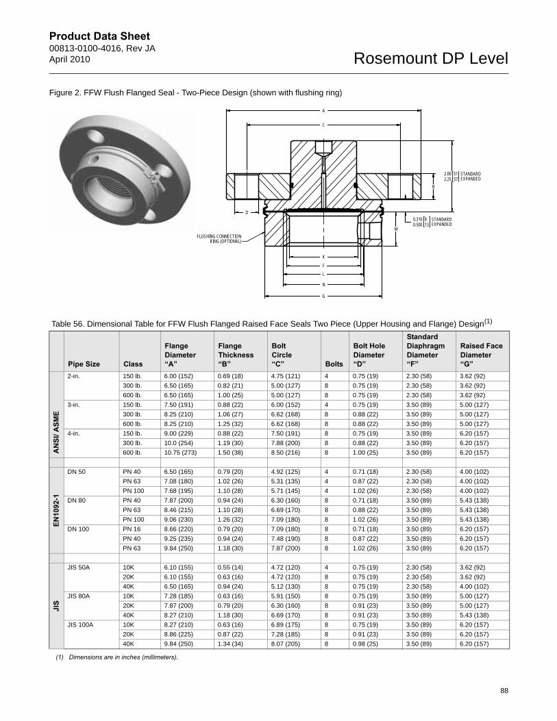
Product Data Sheet00813-0100-4016, Rev JAApril 2010 Rosemount DP Level
88
Figure 2. FFW Flush Flanged Seal - Two-Piece Design (shown with flushing ring)
B
A
G
F
D
2.002.25
5157
0.3100.500
813
M
L
K
N
C
FLUSHING CONNECTIONRING (OPTIONAL)
STANDARDEXPANDED
STANDARDEXPANDED
Table 56. Dimensional Table for FFW Flush Flanged Raised Face Seals Two Piece (Upper Housing and Flange) Design(1)
Pipe Size Class
Flange Diameter“A”
Flange Thickness“B”
Bolt Circle“C” Bolts
Bolt Hole Diameter“D”
Standard Diaphragm Diameter“F”
Raised Face Diameter“G”
AN
SI/ A
SME
2-in. 150 lb. 6.00 (152) 0.69 (18) 4.75 (121) 4 0.75 (19) 2.30 (58) 3.62 (92)
300 lb. 6.50 (165) 0.82 (21) 5.00 (127) 8 0.75 (19) 2.30 (58) 3.62 (92)
600 lb. 6.50 (165) 1.00 (25) 5.00 (127) 8 0.75 (19) 2.30 (58) 3.62 (92)
3-in. 150 lb. 7.50 (191) 0.88 (22) 6.00 (152) 4 0.75 (19) 3.50 (89) 5.00 (127)
300 lb. 8.25 (210) 1.06 (27) 6.62 (168) 8 0.88 (22) 3.50 (89) 5.00 (127)
600 lb. 8.25 (210) 1.25 (32) 6.62 (168) 8 0.88 (22) 3.50 (89) 5.00 (127)
4-in. 150 lb. 9.00 (229) 0.88 (22) 7.50 (191) 8 0.75 (19) 3.50 (89) 6.20 (157)
300 lb. 10.0 (254) 1.19 (30) 7.88 (200) 8 0.88 (22) 3.50 (89) 6.20 (157)
600 lb. 10.75 (273) 1.50 (38) 8.50 (216) 8 1.00 (25) 3.50 (89) 6.20 (157)
EN10
92-1
DN 50 PN 40 6.50 (165) 0.79 (20) 4.92 (125) 4 0.71 (18) 2.30 (58) 4.00 (102)
PN 63 7.08 (180) 1.02 (26) 5.31 (135) 4 0.87 (22) 2.30 (58) 4.00 (102)
PN 100 7.68 (195) 1.10 (28) 5.71 (145) 4 1.02 (26) 2.30 (58) 4.00 (102)
DN 80 PN 40 7.87 (200) 0.94 (24) 6.30 (160) 8 0.71 (18) 3.50 (89) 5.43 (138)
PN 63 8.46 (215) 1.10 (28) 6.69 (170) 8 0.88 (22) 3.50 (89) 5.43 (138)
PN 100 9.06 (230) 1.26 (32) 7.09 (180) 8 1.02 (26) 3.50 (89) 5.43 (138)
DN 100 PN 16 8.66 (220) 0.79 (20) 7.09 (180) 8 0.71 (18) 3.50 (89) 6.20 (157)
PN 40 9.25 (235) 0.94 (24) 7.48 (190) 8 0.87 (22) 3.50 (89) 6.20 (157)
PN 63 9.84 (250) 1.18 (30) 7.87 (200) 8 1.02 (26) 3.50 (89) 6.20 (157)
JIS
JIS 50A 10K 6.10 (155) 0.55 (14) 4.72 (120) 4 0.75 (19) 2.30 (58) 3.62 (92)
20K 6.10 (155) 0.63 (16) 4.72 (120) 8 0.75 (19) 2.30 (58) 3.62 (92)
40K 6.50 (165) 0.94 (24) 5.12 (130) 8 0.75 (19) 2.30 (58) 4.00 (102)
JIS 80A 10K 7.28 (185) 0.63 (16) 5.91 (150) 8 0.75 (19) 3.50 (89) 5.00 (127)
20K 7.87 (200) 0.79 (20) 6.30 (160) 8 0.91 (23) 3.50 (89) 5.00 (127)
40K 8.27 (210) 1.18 (30) 6.69 (170) 8 0.91 (23) 3.50 (89) 5.43 (138)
JIS 100A 10K 8.27 (210) 0.63 (16) 6.89 (175) 8 0.75 (19) 3.50 (89) 6.20 (157)
20K 8.86 (225) 0.87 (22) 7.28 (185) 8 0.91 (23) 3.50 (89) 6.20 (157)
40K 9.84 (250) 1.34 (34) 8.07 (205) 8 0.98 (25) 3.50 (89) 6.20 (157)
(1) Dimensions are in inches (millimeters).
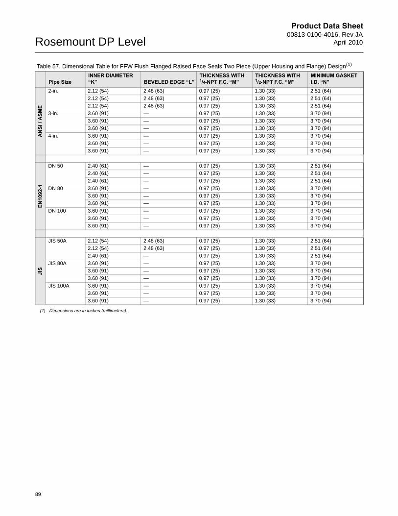
Product Data Sheet00813-0100-4016, Rev JA
April 2010Rosemount DP Level
Table 57. Dimensional Table for FFW Flush Flanged Raised Face Seals Two Piece (Upper Housing and Flange) Design(1)
Pipe SizeINNER DIAMETER “K” BEVELED EDGE “L”
THICKNESS WITH 1/4-NPT F.C. “M”
THICKNESS WITH 1/2-NPT F.C. “M”
MINIMUM GASKET I.D. “N”
AN
SI /
ASM
E
2-in. 2.12 (54) 2.48 (63) 0.97 (25) 1.30 (33) 2.51 (64)
2.12 (54) 2.48 (63) 0.97 (25) 1.30 (33) 2.51 (64)
2.12 (54) 2.48 (63) 0.97 (25) 1.30 (33) 2.51 (64)
3-in. 3.60 (91) — 0.97 (25) 1.30 (33) 3.70 (94)
3.60 (91) — 0.97 (25) 1.30 (33) 3.70 (94)
3.60 (91) — 0.97 (25) 1.30 (33) 3.70 (94)
4-in. 3.60 (91) — 0.97 (25) 1.30 (33) 3.70 (94)
3.60 (91) — 0.97 (25) 1.30 (33) 3.70 (94)
3.60 (91) — 0.97 (25) 1.30 (33) 3.70 (94)
EN10
92-1
DN 50 2.40 (61) — 0.97 (25) 1.30 (33) 2.51 (64)
2.40 (61) — 0.97 (25) 1.30 (33) 2.51 (64)
2.40 (61) — 0.97 (25) 1.30 (33) 2.51 (64)
DN 80 3.60 (91) — 0.97 (25) 1.30 (33) 3.70 (94)
3.60 (91) — 0.97 (25) 1.30 (33) 3.70 (94)
3.60 (91) — 0.97 (25) 1.30 (33) 3.70 (94)
DN 100 3.60 (91) — 0.97 (25) 1.30 (33) 3.70 (94)
3.60 (91) — 0.97 (25) 1.30 (33) 3.70 (94)
3.60 (91) — 0.97 (25) 1.30 (33) 3.70 (94)
JIS
JIS 50A 2.12 (54) 2.48 (63) 0.97 (25) 1.30 (33) 2.51 (64)
2.12 (54) 2.48 (63) 0.97 (25) 1.30 (33) 2.51 (64)
2.40 (61) — 0.97 (25) 1.30 (33) 2.51 (64)
JIS 80A 3.60 (91) — 0.97 (25) 1.30 (33) 3.70 (94)
3.60 (91) — 0.97 (25) 1.30 (33) 3.70 (94)
3.60 (91) — 0.97 (25) 1.30 (33) 3.70 (94)
JIS 100A 3.60 (91) — 0.97 (25) 1.30 (33) 3.70 (94)
3.60 (91) — 0.97 (25) 1.30 (33) 3.70 (94)
3.60 (91) — 0.97 (25) 1.30 (33) 3.70 (94)
(1) Dimensions are in inches (millimeters).
89
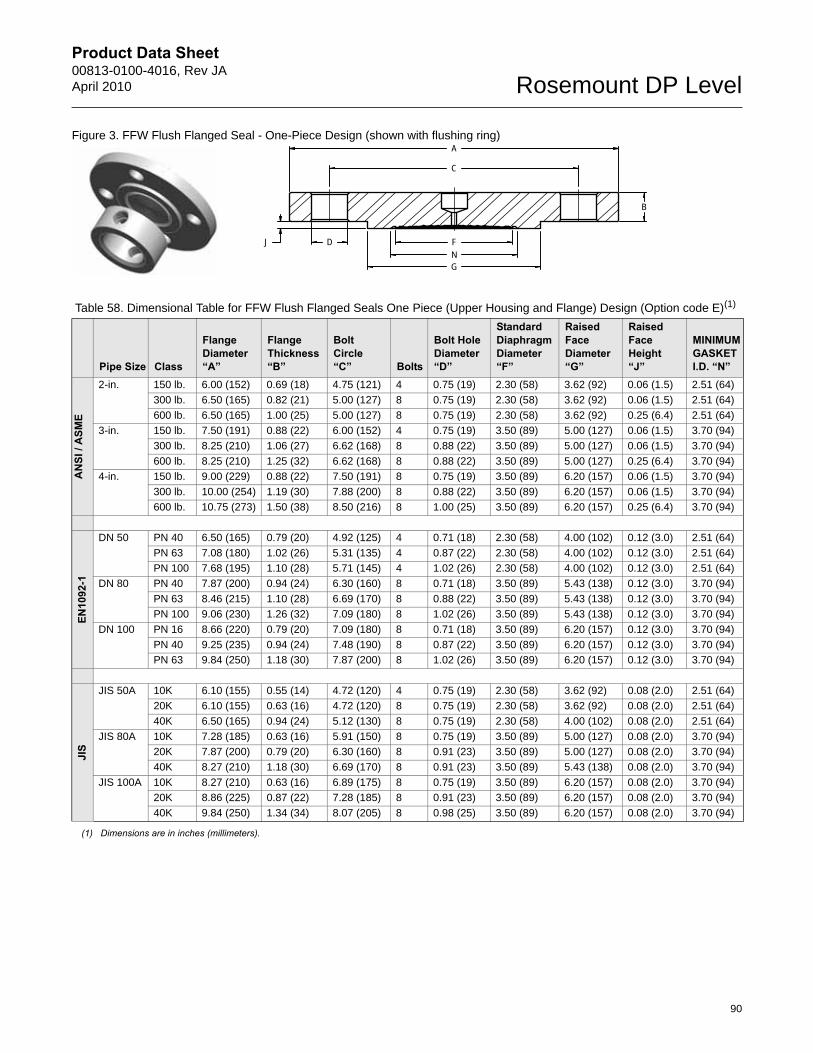
Product Data Sheet00813-0100-4016, Rev JAApril 2010 Rosemount DP Level
Figure 3. FFW Flush Flanged Seal - One-Piece Design (shown with flushing ring) A
G
FN
DJ
B
C
Table 58. Dimensional Table for FFW Flush Flanged Seals One Piece (Upper Housing and Flange) Design (Option code E)(1)
Pipe Size Class
Flange Diameter“A”
Flange Thickness“B”
Bolt Circle“C” Bolts
Bolt Hole Diameter“D”
Standard Diaphragm Diameter“F”
Raised Face Diameter“G”
Raised Face Height“J”
MINIMUM GASKET I.D. “N”
AN
SI /
ASM
E
2-in. 150 lb. 6.00 (152) 0.69 (18) 4.75 (121) 4 0.75 (19) 2.30 (58) 3.62 (92) 0.06 (1.5) 2.51 (64)
300 lb. 6.50 (165) 0.82 (21) 5.00 (127) 8 0.75 (19) 2.30 (58) 3.62 (92) 0.06 (1.5) 2.51 (64)
600 lb. 6.50 (165) 1.00 (25) 5.00 (127) 8 0.75 (19) 2.30 (58) 3.62 (92) 0.25 (6.4) 2.51 (64)
3-in. 150 lb. 7.50 (191) 0.88 (22) 6.00 (152) 4 0.75 (19) 3.50 (89) 5.00 (127) 0.06 (1.5) 3.70 (94)
300 lb. 8.25 (210) 1.06 (27) 6.62 (168) 8 0.88 (22) 3.50 (89) 5.00 (127) 0.06 (1.5) 3.70 (94)
600 lb. 8.25 (210) 1.25 (32) 6.62 (168) 8 0.88 (22) 3.50 (89) 5.00 (127) 0.25 (6.4) 3.70 (94)
4-in. 150 lb. 9.00 (229) 0.88 (22) 7.50 (191) 8 0.75 (19) 3.50 (89) 6.20 (157) 0.06 (1.5) 3.70 (94)
300 lb. 10.00 (254) 1.19 (30) 7.88 (200) 8 0.88 (22) 3.50 (89) 6.20 (157) 0.06 (1.5) 3.70 (94)
600 lb. 10.75 (273) 1.50 (38) 8.50 (216) 8 1.00 (25) 3.50 (89) 6.20 (157) 0.25 (6.4) 3.70 (94)
EN10
92-1
DN 50 PN 40 6.50 (165) 0.79 (20) 4.92 (125) 4 0.71 (18) 2.30 (58) 4.00 (102) 0.12 (3.0) 2.51 (64)
PN 63 7.08 (180) 1.02 (26) 5.31 (135) 4 0.87 (22) 2.30 (58) 4.00 (102) 0.12 (3.0) 2.51 (64)
PN 100 7.68 (195) 1.10 (28) 5.71 (145) 4 1.02 (26) 2.30 (58) 4.00 (102) 0.12 (3.0) 2.51 (64)
DN 80 PN 40 7.87 (200) 0.94 (24) 6.30 (160) 8 0.71 (18) 3.50 (89) 5.43 (138) 0.12 (3.0) 3.70 (94)
PN 63 8.46 (215) 1.10 (28) 6.69 (170) 8 0.88 (22) 3.50 (89) 5.43 (138) 0.12 (3.0) 3.70 (94)
PN 100 9.06 (230) 1.26 (32) 7.09 (180) 8 1.02 (26) 3.50 (89) 5.43 (138) 0.12 (3.0) 3.70 (94)
DN 100 PN 16 8.66 (220) 0.79 (20) 7.09 (180) 8 0.71 (18) 3.50 (89) 6.20 (157) 0.12 (3.0) 3.70 (94)
PN 40 9.25 (235) 0.94 (24) 7.48 (190) 8 0.87 (22) 3.50 (89) 6.20 (157) 0.12 (3.0) 3.70 (94)
PN 63 9.84 (250) 1.18 (30) 7.87 (200) 8 1.02 (26) 3.50 (89) 6.20 (157) 0.12 (3.0) 3.70 (94)
JIS
JIS 50A 10K 6.10 (155) 0.55 (14) 4.72 (120) 4 0.75 (19) 2.30 (58) 3.62 (92) 0.08 (2.0) 2.51 (64)
20K 6.10 (155) 0.63 (16) 4.72 (120) 8 0.75 (19) 2.30 (58) 3.62 (92) 0.08 (2.0) 2.51 (64)
40K 6.50 (165) 0.94 (24) 5.12 (130) 8 0.75 (19) 2.30 (58) 4.00 (102) 0.08 (2.0) 2.51 (64)
JIS 80A 10K 7.28 (185) 0.63 (16) 5.91 (150) 8 0.75 (19) 3.50 (89) 5.00 (127) 0.08 (2.0) 3.70 (94)
20K 7.87 (200) 0.79 (20) 6.30 (160) 8 0.91 (23) 3.50 (89) 5.00 (127) 0.08 (2.0) 3.70 (94)
40K 8.27 (210) 1.18 (30) 6.69 (170) 8 0.91 (23) 3.50 (89) 5.43 (138) 0.08 (2.0) 3.70 (94)
JIS 100A 10K 8.27 (210) 0.63 (16) 6.89 (175) 8 0.75 (19) 3.50 (89) 6.20 (157) 0.08 (2.0) 3.70 (94)
20K 8.86 (225) 0.87 (22) 7.28 (185) 8 0.91 (23) 3.50 (89) 6.20 (157) 0.08 (2.0) 3.70 (94)
40K 9.84 (250) 1.34 (34) 8.07 (205) 8 0.98 (25) 3.50 (89) 6.20 (157) 0.08 (2.0) 3.70 (94)
(1) Dimensions are in inches (millimeters).
90
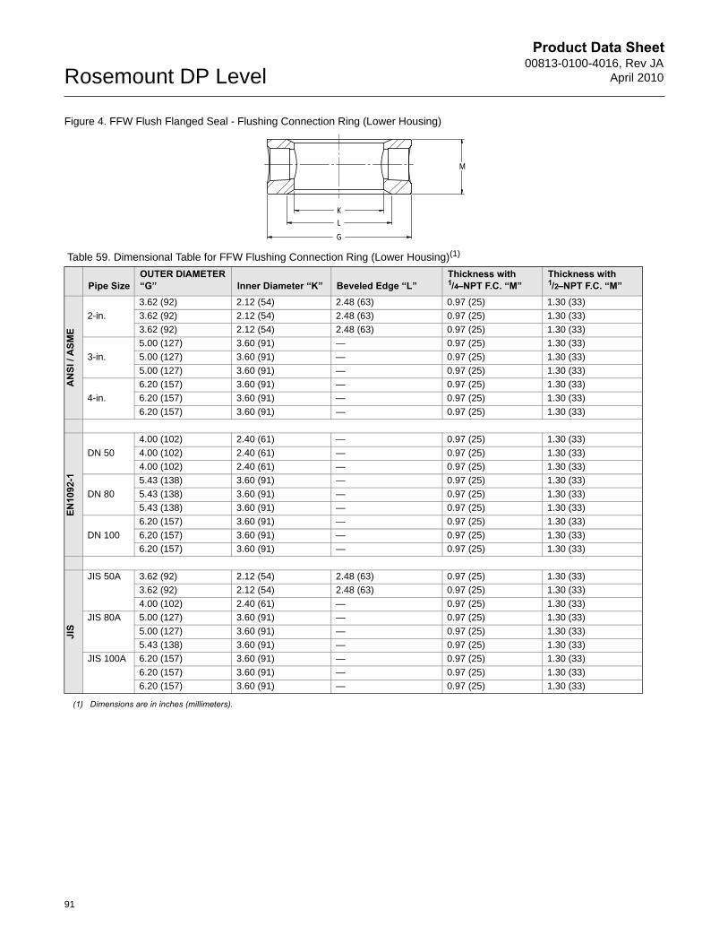
Product Data Sheet00813-0100-4016, Rev JA
April 2010Rosemount DP Level
Figure 4. FFW Flush Flanged Seal - Flushing Connection Ring (Lower Housing)
Table 59. Dimensional Table for FFW Flushing Connection Ring (Lower Housing)(1)
(1) Dimensions are in inches (millimeters).
Pipe SizeOUTER DIAMETER “G” Inner Diameter “K” Beveled Edge “L”
Thickness with 1/4–NPT F.C. “M”
Thickness with 1/2–NPT F.C. “M”
AN
SI /
ASM
E
2-in.
3.62 (92) 2.12 (54) 2.48 (63) 0.97 (25) 1.30 (33)
3.62 (92) 2.12 (54) 2.48 (63) 0.97 (25) 1.30 (33)
3.62 (92) 2.12 (54) 2.48 (63) 0.97 (25) 1.30 (33)
3-in.
5.00 (127) 3.60 (91) — 0.97 (25) 1.30 (33)
5.00 (127) 3.60 (91) — 0.97 (25) 1.30 (33)
5.00 (127) 3.60 (91) — 0.97 (25) 1.30 (33)
4-in.
6.20 (157) 3.60 (91) — 0.97 (25) 1.30 (33)
6.20 (157) 3.60 (91) — 0.97 (25) 1.30 (33)
6.20 (157) 3.60 (91) — 0.97 (25) 1.30 (33)
EN10
92-1
DN 50
4.00 (102) 2.40 (61) — 0.97 (25) 1.30 (33)
4.00 (102) 2.40 (61) — 0.97 (25) 1.30 (33)
4.00 (102) 2.40 (61) — 0.97 (25) 1.30 (33)
DN 80
5.43 (138) 3.60 (91) — 0.97 (25) 1.30 (33)
5.43 (138) 3.60 (91) — 0.97 (25) 1.30 (33)
5.43 (138) 3.60 (91) — 0.97 (25) 1.30 (33)
DN 100
6.20 (157) 3.60 (91) — 0.97 (25) 1.30 (33)
6.20 (157) 3.60 (91) — 0.97 (25) 1.30 (33)
6.20 (157) 3.60 (91) — 0.97 (25) 1.30 (33)
JIS
JIS 50A 3.62 (92) 2.12 (54) 2.48 (63) 0.97 (25) 1.30 (33)
3.62 (92) 2.12 (54) 2.48 (63) 0.97 (25) 1.30 (33)
4.00 (102) 2.40 (61) — 0.97 (25) 1.30 (33)
JIS 80A 5.00 (127) 3.60 (91) — 0.97 (25) 1.30 (33)
5.00 (127) 3.60 (91) — 0.97 (25) 1.30 (33)
5.43 (138) 3.60 (91) — 0.97 (25) 1.30 (33)
JIS 100A 6.20 (157) 3.60 (91) — 0.97 (25) 1.30 (33)
6.20 (157) 3.60 (91) — 0.97 (25) 1.30 (33)
6.20 (157) 3.60 (91) — 0.97 (25) 1.30 (33)
M
LK
G
91
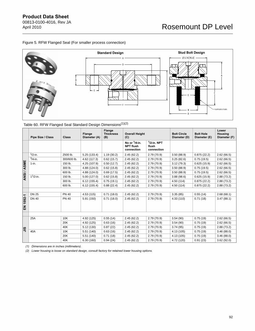
Product Data Sheet00813-0100-4016, Rev JAApril 2010 Rosemount DP Level
Figure 5. RFW Flanged Seal (For smaller process connection)
Table 60. RFW Flanged Seal Standard Design Dimensions(1)(2)
(1) Dimensions are in inches (millimeters).(2) Lower housing is loose on standard design, consult factory for retained lower housing options.
Pipe Size / Class ClassFlange Diameter (A)
Flange Thickness (B)
Overall Height (C)
Bolt Circle Diameter (D)
Bolt Hole Diameter (E)
Lower Housing Diameter (F)
No or 1/4-in. NPT flush connection
1/2-in. NPT flush connection
AN
SI /
ASM
E
1/2-in. 2500 lb. 5.25 (133.4) 1.19 (30.2) 2.45 (62.2) 2.79 (70.9) 3.50 (88.9) 0.875 (22.2) 2.62 (66.5)3/4-in. 300/600 lb. 4.62 (117.3) 0.62 (15.7) 2.45 (62.2) 2.79 (70.9) 3.25 (82.6) 0.75 (19.5) 2.62 (66.5)
1-in. 150 lb. 4.25 (107.9) 0.50 (12.7) 2.45 (62.2) 2.79 (70.9) 3.12 (79.3) 0.625 (15.9) 2.62 (66.5)
300 lb. 4.88 (124.0) 0.62 (15.8) 2.45 (62.2) 2.79 (70.9) 3.50 (88.9) 0.75 (19.5) 2.62 (66.5)
600 lb. 4.88 (124.0) 0.69 (17.5) 2.45 (62.2) 2.79 (70.9) 3.50 (88.9) 0.75 (19.5) 2.62 (66.5)
11/2-in. 150 lb. 5.00 (127.0) 0.62 (15.8) 2.45 (62.2) 2.79 (70.9) 3.88 (98.6) 0.625 (15.9) 2.88 (73.2)
300 lb. 6.12 (155.4) 0.75 (19.1) 2.45 (62.2) 2.79 (70.9) 4.50 (114) 0.875 (22.2) 2.88 (73.2)
600 lb. 6.12 (155.4) 0.88 (22.4) 2.45 (62.2) 2.79 (70.9) 4.50 (114) 0.875 (22.2) 2.88 (73.2)
EN 1
092-
1 DN 25 PN 40 4.53 (115) 0.71 (18.0) 2.45 (62.2) 2.79 (70.9) 3.35 (85) 0.55 (14) 2.68 (68.1)
DN 40 PN 40 5.91 (150) 0.71 (18.0) 2.45 (62.2) 2.79 (70.9) 4.33 (110) 0.71 (18) 3.47 (88.1)
JIS
25A 10K 4.92 (125) 0.55 (14) 2.45 (62.2) 2.79 (70.9) 3.54 (90) 0.75 (19) 2.62 (66.5)
20K 4.92 (125) 0.63 (16) 2.45 (62.2) 2.79 (70.9) 3.54 (90) 0.75 (19) 2.62 (66.5)
40K 5.12 (130) 0.87 (22) 2.45 (62.2) 2.79 (70.9) 3.74 (95) 0.75 (19) 2.88 (73.2)
40A 10K 5.51 (140) 0.63 (16) 2.45 (62.2) 2.79 (70.9) 4.13 (105) 0.75 (19) 3.46 (88.0)
20K 5.51 (140) 0.71 (18) 2.45 (62.2) 2.79 (70.9) 4.13 (105) 0.75 (19) 3.46 (88.0)
40K 6.30 (160) 0.94 (24) 2.45 (62.2) 2.79 (70.9) 4.72 (120) 0.91 (23) 3.62 (92.0)
A
C
E
F
B
D
A
3.74 95.0
D
EC
B SUPPLIED STUDS
Standard Design Stud Bolt Design
92
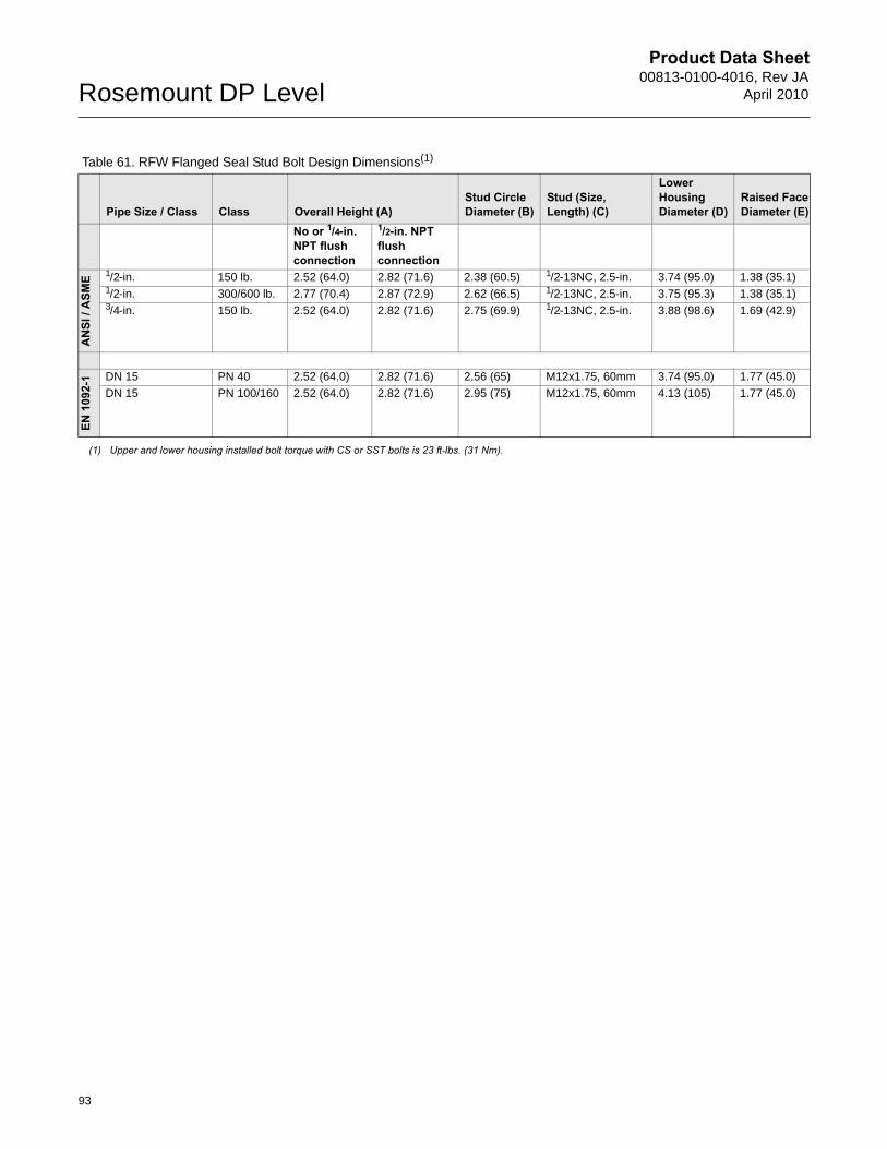
Product Data Sheet00813-0100-4016, Rev JA
April 2010Rosemount DP Level
Table 61. RFW Flanged Seal Stud Bolt Design Dimensions(1)
Pipe Size / Class Class Overall Height (A)Stud Circle Diameter (B)
Stud (Size, Length) (C)
Lower Housing Diameter (D)
Raised Face Diameter (E)
No or 1/4-in. NPT flush connection
1/2-in. NPT flush connection
AN
SI /
ASM
E 1/2-in. 150 lb. 2.52 (64.0) 2.82 (71.6) 2.38 (60.5) 1/2-13NC, 2.5-in. 3.74 (95.0) 1.38 (35.1)1/2-in. 300/600 lb. 2.77 (70.4) 2.87 (72.9) 2.62 (66.5) 1/2-13NC, 2.5-in. 3.75 (95.3) 1.38 (35.1)3/4-in. 150 lb. 2.52 (64.0) 2.82 (71.6) 2.75 (69.9) 1/2-13NC, 2.5-in. 3.88 (98.6) 1.69 (42.9)
EN 1
092-
1 DN 15 PN 40 2.52 (64.0) 2.82 (71.6) 2.56 (65) M12x1.75, 60mm 3.74 (95.0) 1.77 (45.0)
DN 15 PN 100/160 2.52 (64.0) 2.82 (71.6) 2.95 (75) M12x1.75, 60mm 4.13 (105) 1.77 (45.0)
(1) Upper and lower housing installed bolt torque with CS or SST bolts is 23 ft-lbs. (31 Nm).
93
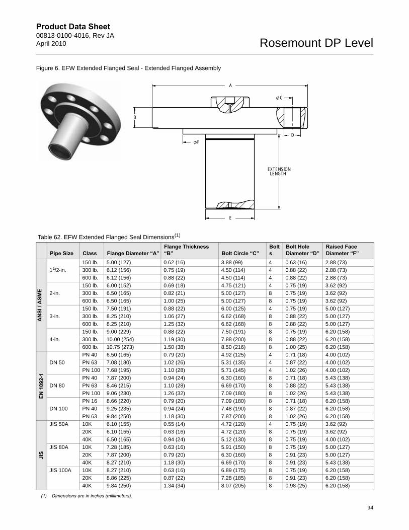
Product Data Sheet00813-0100-4016, Rev JAApril 2010 Rosemount DP Level
Figure 6. EFW Extended Flanged Seal - Extended Flanged Assembly
Table 62. EFW Extended Flanged Seal Dimensions(1)
(1) Dimensions are in inches (millimeters).
Pipe Size Class Flange Diameter “A”Flange Thickness “B” Bolt Circle “C”
Bolts
Bolt Hole Diameter “D”
Raised Face Diameter “F”
AN
SI /
ASM
E
11/2-in.
150 lb. 5.00 (127) 0.62 (16) 3.88 (99) 4 0.63 (16) 2.88 (73)
300 lb. 6.12 (156) 0.75 (19) 4.50 (114) 4 0.88 (22) 2.88 (73)
600 lb. 6.12 (156) 0.88 (22) 4.50 (114) 4 0.88 (22) 2.88 (73)
2-in.
150 lb. 6.00 (152) 0.69 (18) 4.75 (121) 4 0.75 (19) 3.62 (92)
300 lb. 6.50 (165) 0.82 (21) 5.00 (127) 8 0.75 (19) 3.62 (92)
600 lb. 6.50 (165) 1.00 (25) 5.00 (127) 8 0.75 (19) 3.62 (92)
3-in.
150 lb. 7.50 (191) 0.88 (22) 6.00 (125) 4 0.75 (19) 5.00 (127)
300 lb. 8.25 (210) 1.06 (27) 6.62 (168) 8 0.88 (22) 5.00 (127)
600 lb. 8.25 (210) 1.25 (32) 6.62 (168) 8 0.88 (22) 5.00 (127)
4-in.
150 lb. 9.00 (229) 0.88 (22) 7.50 (191) 8 0.75 (19) 6.20 (158)
300 lb. 10.00 (254) 1.19 (30) 7.88 (200) 8 0.88 (22) 6.20 (158)
600 lb. 10.75 (273) 1.50 (38) 8.50 (216) 8 1.00 (25) 6.20 (158)
EN 1
092-
1
DN 50
PN 40 6.50 (165) 0.79 (20) 4.92 (125) 4 0.71 (18) 4.00 (102)
PN 63 7.08 (180) 1.02 (26) 5.31 (135) 4 0.87 (22) 4.00 (102)
PN 100 7.68 (195) 1.10 (28) 5.71 (145) 4 1.02 (26) 4.00 (102)
DN 80
PN 40 7.87 (200) 0.94 (24) 6.30 (160) 8 0.71 (18) 5.43 (138)
PN 63 8.46 (215) 1.10 (28) 6.69 (170) 8 0.88 (22) 5.43 (138)
PN 100 9.06 (230) 1.26 (32) 7.09 (180) 8 1.02 (26) 5.43 (138)
DN 100
PN 16 8.66 (220) 0.79 (20) 7.09 (180) 8 0.71 (18) 6.20 (158)
PN 40 9.25 (235) 0.94 (24) 7.48 (190) 8 0.87 (22) 6.20 (158)
PN 63 9.84 (250) 1.18 (30) 7.87 (200) 8 1.02 (26) 6.20 (158)
JIS
JIS 50A 10K 6.10 (155) 0.55 (14) 4.72 (120) 4 0.75 (19) 3.62 (92)
20K 6.10 (155) 0.63 (16) 4.72 (120) 8 0.75 (19) 3.62 (92)
40K 6.50 (165) 0.94 (24) 5.12 (130) 8 0.75 (19) 4.00 (102)
JIS 80A 10K 7.28 (185) 0.63 (16) 5.91 (150) 8 0.75 (19) 5.00 (127)
20K 7.87 (200) 0.79 (20) 6.30 (160) 8 0.91 (23) 5.00 (127)
40K 8.27 (210) 1.18 (30) 6.69 (170) 8 0.91 (23) 5.43 (138)
JIS 100A 10K 8.27 (210) 0.63 (16) 6.89 (175) 8 0.75 (19) 6.20 (158)
20K 8.86 (225) 0.87 (22) 7.28 (185) 8 0.91 (23) 6.20 (158)
40K 9.84 (250) 1.34 (34) 8.07 (205) 8 0.98 (25) 6.20 (158)
C
A
F
LENGTHEXTENSION
E
D
B
94
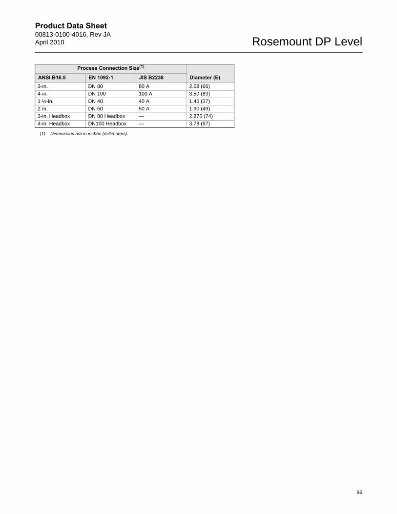
Product Data Sheet00813-0100-4016, Rev JAApril 2010 Rosemount DP Level
Process Connection Size(1)
Diameter (E)ANSI B16.5 EN 1092-1 JIS B22383-in. DN 80 80 A 2.58 (66)
4-in. DN 100 100 A 3.50 (89)
1 ½-in. DN 40 40 A 1.45 (37)
2-in. DN 50 50 A 1.90 (49)
3-in. Headbox DN 80 Headbox — 2.875 (74)
4-in. Headbox DN100 Headbox — 3.78 (97)
(1) Dimensions are in inches (millimeters).
95
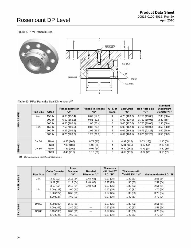
Product Data Sheet00813-0100-4016, Rev JA
April 2010Rosemount DP Level
Figure 7. PFW Pancake Seal
Table 63. PFW Pancake Seal Dimensions(1)
(1) Dimensions are in inches (millimeters).
AN
SI /
ASM
E Pipe Size ClassFlange Diameter
“A”Flange Thickness
“B”QTY. of Bolts
Bolt Circle“C”
Bolt Hole Size “D”
Standard Diaphragm
Diameter “F”2-in. 150 lb. 6.00 (152.4) 0.69 (17.5) 4 4.75 (120.7) 0.750 (19.05) 2.30 (58.4)
300 lb. 6.50 (165.1) 0.81 (20.6) 8 5.00 (127.0) 0.750 (19.05) 2.30 (58.4)
600 lb. 6.50 (165.1) 1.00 (25.4) 8 5.00 (127.0) 0.750 (19.05) 2.30 (58.4)
3-in. 150 lb. 7.50 (190.5) 0.88 (22.4) 4 6.00 (152.4) 0.750 (19.05) 3.50 (88.9)
300 lb. 8.25 (209.6) 1.06 (26.9) 8 6.62 (168.1) 0.875 (22.23) 3.50 (88.9)
600 lb. 8.25 (209.6) 1.25 (31.8) 8 6.62 (168.1) 0.875 (22.23) 3.50 (88.9)
EN10
92-1 DN 50 PN40 6.50 (165) 0.79 (20) 4 4.92 (125) 0.71 (18)) 2.30 (58)
PN63 7.09 (180) 1.02 (26) 4 5.31 (135) 0.87 (22) 2.30 (58)
DN 80 PN40 7.87 (200) 0.94 (24) 8 6.30 (160) 0.71 (18) 3.50 (89)
PN63 8.46 (215) 1.10 (28) 8 6.69 (170) 0.87 (22) 3.50 (89)
B
A
D
M
1.00 (25.4)
K
G
F
NL
C
SOCKET HEADCAP SCREW
FLUSH RING
GASKETDIAPHRAGM
AN
SI /
ASM
E Pipe SizeOuter Diameter
“G”
Inner Diameter
“K”Beveled
Diameter “L”
Thickness with 1/4-NPT
F.C. “M”Thickness with 1/2-NPT F.C. “M” Minimum Gasket I.D. “N”
2-in. 3.62 (92) 2.12 (54) 2.48 (63) 0.97 (25) 1.30 (33) 2.51 (64)
3.62 (92) 2.12 (54) 2.48 (63) 0.97 (25) 1.30 (33) 2.51 (64)
3.62 (92) 2.12 (54) 2.48 (63) 0.97 (25) 1.30 (33) 2.51 (64)
3-in. 5.00 (127) 3.60 (91) — 0.97 (25) 1.30 (33) 3.70 (94)
5.00 (127) 3.60 (91) — 0.97 (25) 1.30 (33) 3.70 (94)
5.00 (127) 3.60 (91) — 0.97 (25) 1.30 (33) 3.70 (94)
EN10
92-1 DN 50 4.00 (102) 2.40 (61) — 0.97 (25) 1.30 (33) 2.51 (64)
4.00 (102) 2.40 (61) — 0.97 (25) 1.30 (33) 2.51 (64)
DN 80 5.43 (138) 3.60 (91) — 0.97 (25) 1.30 (33) 3.70 (94)
5.43 (138) 3.60 (91) — 0.97 (25) 1.30 (33) 3.70 (94)
96
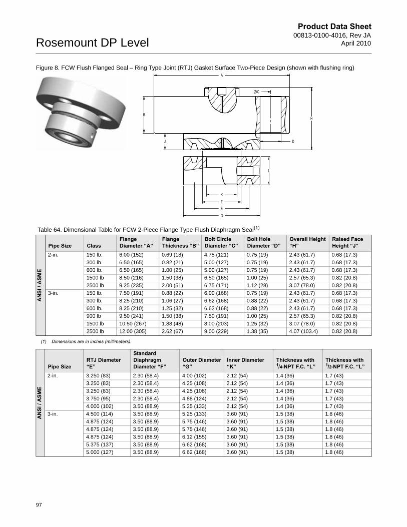
Product Data Sheet00813-0100-4016, Rev JA
April 2010Rosemount DP Level
Figure 8. FCW Flush Flanged Seal – Ring Type Joint (RTJ) Gasket Surface Two-Piece Design (shown with flushing ring)
Table 64. Dimensional Table for FCW 2-Piece Flange Type Flush Diaphragm Seal(1)
AN
SI /
ASM
E
Pipe Size ClassFlange Diameter “A”
Flange Thickness “B”
Bolt Circle Diameter “C”
Bolt Hole Diameter “D”
Overall Height “H”
Raised Face Height “J”
2-in. 150 lb. 6.00 (152) 0.69 (18) 4.75 (121) 0.75 (19) 2.43 (61.7) 0.68 (17.3)
300 lb. 6.50 (165) 0.82 (21) 5.00 (127) 0.75 (19) 2.43 (61.7) 0.68 (17.3)
600 lb. 6.50 (165) 1.00 (25) 5.00 (127) 0.75 (19) 2.43 (61.7) 0.68 (17.3)
1500 lb 8.50 (216) 1.50 (38) 6.50 (165) 1.00 (25) 2.57 (65.3) 0.82 (20.8)
2500 lb 9.25 (235) 2.00 (51) 6.75 (171) 1.12 (28) 3.07 (78.0) 0.82 (20.8)
3-in. 150 lb. 7.50 (191) 0.88 (22) 6.00 (168) 0.75 (19) 2.43 (61.7) 0.68 (17.3)
300 lb. 8.25 (210) 1.06 (27) 6.62 (168) 0.88 (22) 2.43 (61.7) 0.68 (17.3)
600 lb. 8.25 (210) 1.25 (32) 6.62 (168) 0.88 (22) 2.43 (61.7) 0.68 (17.3)
900 lb 9.50 (241) 1.50 (38) 7.50 (191) 1.00 (25) 2.57 (65.3) 0.82 (20.8)
1500 lb 10.50 (267) 1.88 (48) 8.00 (203) 1.25 (32) 3.07 (78.0) 0.82 (20.8)
2500 lb 12.00 (305) 2.62 (67) 9.00 (229) 1.38 (35) 4.07 (103.4) 0.82 (20.8)
(1) Dimensions are in inches (millimeters).
AN
SI /
ASM
E
Pipe SizeRTJ Diameter “E”
Standard Diaphragm Diameter “F”
Outer Diameter “G”
Inner Diameter “K”
Thickness with 1/4-NPT F.C. “L”
Thickness with 1/2-NPT F.C. “L”
2-in. 3.250 (83) 2.30 (58.4) 4.00 (102) 2.12 (54) 1.4 (36) 1.7 (43)
3.250 (83) 2.30 (58.4) 4.25 (108) 2.12 (54) 1.4 (36) 1.7 (43)
3.250 (83) 2.30 (58.4) 4.25 (108) 2.12 (54) 1.4 (36) 1.7 (43)
3.750 (95) 2.30 (58.4) 4.88 (124) 2.12 (54) 1.4 (36) 1.7 (43)
4.000 (102) 3.50 (88.9) 5.25 (133) 2.12 (54) 1.4 (36) 1.7 (43)
3-in. 4.500 (114) 3.50 (88.9) 5.25 (133) 3.60 (91) 1.5 (38) 1.8 (46)
4.875 (124) 3.50 (88.9) 5.75 (146) 3.60 (91) 1.5 (38) 1.8 (46)
4.875 (124) 3.50 (88.9) 5.75 (146) 3.60 (91) 1.5 (38) 1.8 (46)
4.875 (124) 3.50 (88.9) 6.12 (155) 3.60 (91) 1.5 (38) 1.8 (46)
5.375 (137) 3.50 (88.9) 6.62 (168) 3.60 (91) 1.5 (38) 1.8 (46)
5.000 (127) 3.50 (88.9) 6.62 (168) 3.60 (91) 1.5 (38) 1.8 (46)
97
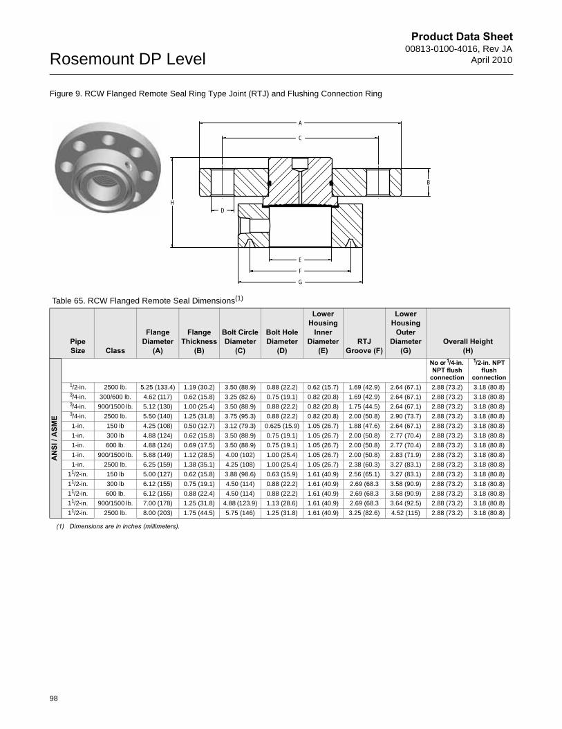
Product Data Sheet00813-0100-4016, Rev JA
April 2010Rosemount DP Level
Figure 9. RCW Flanged Remote Seal Ring Type Joint (RTJ) and Flushing Connection Ring
Table 65. RCW Flanged Remote Seal Dimensions(1)
(1) Dimensions are in inches (millimeters).
Pipe Size Class
Flange Diameter
(A)
Flange Thickness
(B)
Bolt Circle Diameter
(C)
Bolt Hole Diameter
(D)
Lower Housing
Inner Diameter
(E) RTJ
Groove (F)
Lower Housing
Outer Diameter
(G)Overall Height
(H)
AN
SI /
ASM
E
No or 1/4-in. NPT flush
connection
1/2-in. NPT flush
connection1/2-in. 2500 lb. 5.25 (133.4) 1.19 (30.2) 3.50 (88.9) 0.88 (22.2) 0.62 (15.7) 1.69 (42.9) 2.64 (67.1) 2.88 (73.2) 3.18 (80.8)3/4-in. 300/600 lb. 4.62 (117) 0.62 (15.8) 3.25 (82.6) 0.75 (19.1) 0.82 (20.8) 1.69 (42.9) 2.64 (67.1) 2.88 (73.2) 3.18 (80.8)3/4-in. 900/1500 lb. 5.12 (130) 1.00 (25.4) 3.50 (88.9) 0.88 (22.2) 0.82 (20.8) 1.75 (44.5) 2.64 (67.1) 2.88 (73.2) 3.18 (80.8)3/4-in. 2500 lb. 5.50 (140) 1.25 (31.8) 3.75 (95.3) 0.88 (22.2) 0.82 (20.8) 2.00 (50.8) 2.90 (73.7) 2.88 (73.2) 3.18 (80.8)
1-in. 150 lb 4.25 (108) 0.50 (12.7) 3.12 (79.3) 0.625 (15.9) 1.05 (26.7) 1.88 (47.6) 2.64 (67.1) 2.88 (73.2) 3.18 (80.8)
1-in. 300 lb 4.88 (124) 0.62 (15.8) 3.50 (88.9) 0.75 (19.1) 1.05 (26.7) 2.00 (50.8) 2.77 (70.4) 2.88 (73.2) 3.18 (80.8)
1-in. 600 lb. 4.88 (124) 0.69 (17.5) 3.50 (88.9) 0.75 (19.1) 1.05 (26.7) 2.00 (50.8) 2.77 (70.4) 2.88 (73.2) 3.18 (80.8)
1-in. 900/1500 lb. 5.88 (149) 1.12 (28.5) 4.00 (102) 1.00 (25.4) 1.05 (26.7) 2.00 (50.8) 2.83 (71.9) 2.88 (73.2) 3.18 (80.8)
1-in. 2500 lb. 6.25 (159) 1.38 (35.1) 4.25 (108) 1.00 (25.4) 1.05 (26.7) 2.38 (60.3) 3.27 (83.1) 2.88 (73.2) 3.18 (80.8)
11/2-in. 150 lb 5.00 (127) 0.62 (15.8) 3.88 (98.6) 0.63 (15.9) 1.61 (40.9) 2.56 (65.1) 3.27 (83.1) 2.88 (73.2) 3.18 (80.8)
11/2-in. 300 lb 6.12 (155) 0.75 (19.1) 4.50 (114) 0.88 (22.2) 1.61 (40.9) 2.69 (68.3 3.58 (90.9) 2.88 (73.2) 3.18 (80.8)
11/2-in. 600 lb. 6.12 (155) 0.88 (22.4) 4.50 (114) 0.88 (22.2) 1.61 (40.9) 2.69 (68.3 3.58 (90.9) 2.88 (73.2) 3.18 (80.8)
11/2-in. 900/1500 lb. 7.00 (178) 1.25 (31.8) 4.88 (123.9) 1.13 (28.6) 1.61 (40.9) 2.69 (68.3 3.64 (92.5) 2.88 (73.2) 3.18 (80.8)
11/2-in. 2500 lb. 8.00 (203) 1.75 (44.5) 5.75 (146) 1.25 (31.8) 1.61 (40.9) 3.25 (82.6) 4.52 (115) 2.88 (73.2) 3.18 (80.8)
A
G
E
B
HD
C
F
98
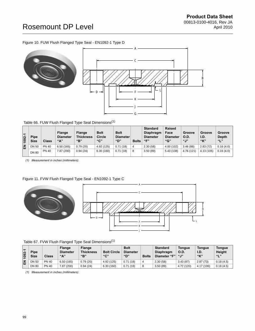
Product Data Sheet00813-0100-4016, Rev JA
April 2010Rosemount DP Level
Figure 10. FUW Flush Flanged Type Seal - EN1092-1 Type D
Figure 11. FVW Flush Flanged Type Seal - EN1092-1 Type C
Table 66. FUW Flush Flanged Type Seal Dimensions(1)
(1) Measurement in inches (millimeters).
EN 1
092-
1
Pipe Size Class
Flange Diameter“A”
Flange Thickness “B”
Bolt Circle“C”
Bolt Diameter “D” Bolts
Standard DiaphragmDiameter “F”
Raised Face Diameter “G”
Groove O.D. “J”
Groove I.D.“K”
Groove Depth“L”
DN 50 PN 40 6.50 (165) 0.79 (20) 4.92 (125) 0.71 (18) 4 2.30 (58) 4.00 (102) 3.46 (88) 2.83 (72) 0.16 (4.0)
DN 80PN 40 7.87 (200) 0.94 (24) 6.30 (160) 0.71 (18) 8 3.50 (89) 5.43 (138) 4.76 (121) 4.13 (105) 0.16 (4.0)
A
G
FD
B
J
K
L
C
A
FD
B
J
K
L
C
Table 67. FVW Flush Flanged Type Seal Dimensions(1)
EN 1
092-
1
Pipe Size Class
Flange Diameter“A”
Flange Thickness “B”
Bolt Circle“C”
Bolt Diameter “D” Bolts
Standard DiaphragmDiameter “F”
Tongue O.D. “J”
Tongue I.D.“K”
Tongue Height“L”
DN 50 PN 40 6.50 (165) 0.79 (20) 4.92 (125) 0.71 (18) 4 2.30 (58) 3.43 (87) 2.87 (73) 0.18 (4.5)
DN 80 PN 40 7.87 (200) 0.94 (24) 6.30 (160) 0.71 (18) 8 3.50 (89) 4.72 (120) 4.17 (106) 0.18 (4.5)
(1) Measurement in inches (millimeters).
99
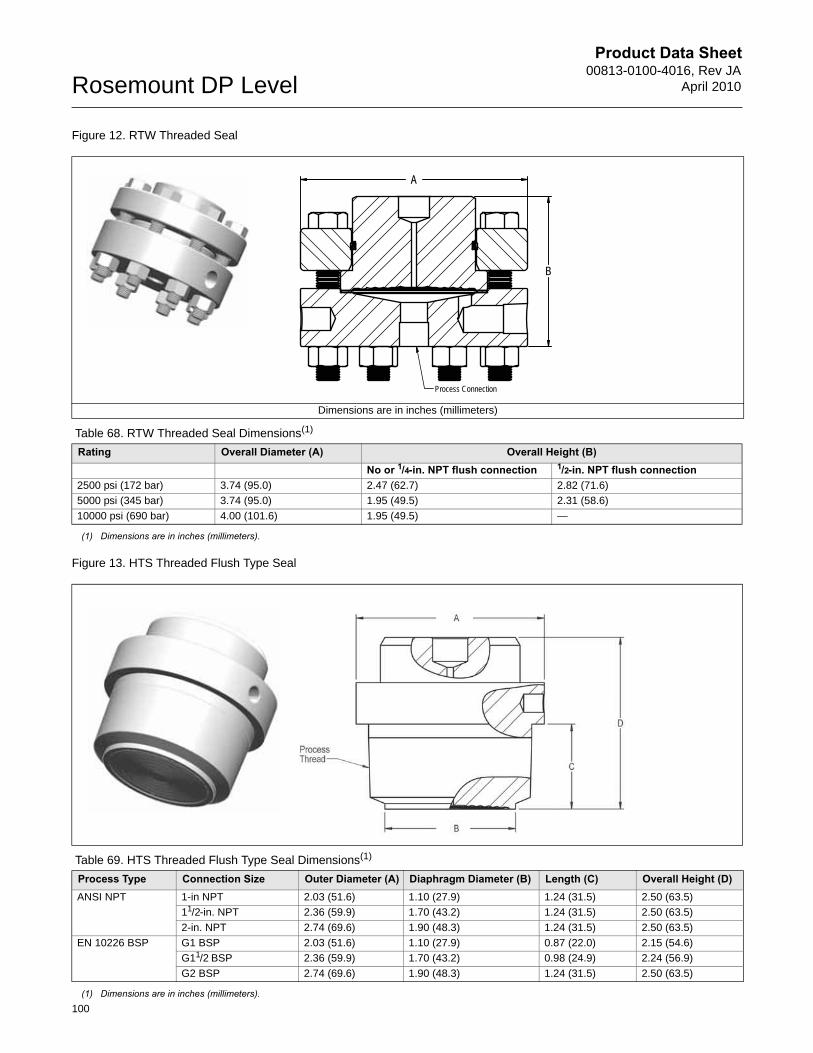
Product Data Sheet00813-0100-4016, Rev JA
April 2010Rosemount DP Level
100
Figure 12. RTW Threaded Seal
Figure 13. HTS Threaded Flush Type Seal
Dimensions are in inches (millimeters)
Table 68. RTW Threaded Seal Dimensions(1)
(1) Dimensions are in inches (millimeters).
Rating Overall Diameter (A) Overall Height (B)No or 1/4-in. NPT flush connection 1/2-in. NPT flush connection
2500 psi (172 bar) 3.74 (95.0) 2.47 (62.7) 2.82 (71.6)
5000 psi (345 bar) 3.74 (95.0) 1.95 (49.5) 2.31 (58.6)
10000 psi (690 bar) 4.00 (101.6) 1.95 (49.5) —
Table 69. HTS Threaded Flush Type Seal Dimensions(1)
(1) Dimensions are in inches (millimeters).
Process Type Connection Size Outer Diameter (A) Diaphragm Diameter (B) Length (C) Overall Height (D)ANSI NPT 1-in NPT 2.03 (51.6) 1.10 (27.9) 1.24 (31.5) 2.50 (63.5)
11/2-in. NPT 2.36 (59.9) 1.70 (43.2) 1.24 (31.5) 2.50 (63.5)
2-in. NPT 2.74 (69.6) 1.90 (48.3) 1.24 (31.5) 2.50 (63.5)
EN 10226 BSP G1 BSP 2.03 (51.6) 1.10 (27.9) 0.87 (22.0) 2.15 (54.6)
G11/2 BSP 2.36 (59.9) 1.70 (43.2) 0.98 (24.9) 2.24 (56.9)
G2 BSP 2.74 (69.6) 1.90 (48.3) 1.24 (31.5) 2.50 (63.5)
A
B
Process Connection
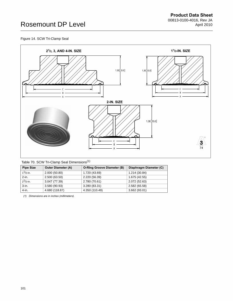
Product Data Sheet00813-0100-4016, Rev JA
April 2010Rosemount DP Level
Figure 14. SCW Tri-Clamp Seal
Table 70. SCW Tri-Clamp Seal Dimensions(1)
(1) Dimensions are in inches (millimeters).
Pipe Size Outer Diameter (A) O-RIng Groove Diameter (B) Diaphragm Diameter (C)11/2-in. 2.000 (50.80) 1.720 (43.69) 1.214 (30.84)
2-in. 2.500 (63.50) 2.220 (56.39) 1.675 (42.55)
21/2-in. 3.047 (77.39) 2.780 (70.61) 2.072 (52.63)
3-in. 3.580 (90.93) 3.280 (83.31) 2.582 (65.58)
4-in. 4.680 (118.87) 4.350 (110.49) 3.662 (93.01)
1.30 33.0
CBA
1.30 33.0
ABC
1.30 33.0
ABC
11/2-IN. SIZE
2-IN. SIZE
21/2, 3, AND 4-IN. SIZE
R
37-01
74
101
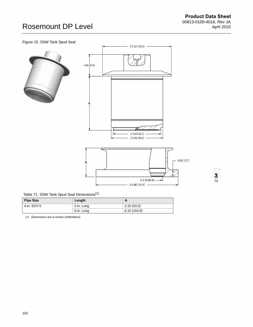
Product Data Sheet00813-0100-4016, Rev JA
April 2010Rosemount DP Level
102
Figure 15. SSW Tank Spud Seal
3.63 92.23.93 99.8
5.22 132.6
1.64 41.8
A
5.98 151.93.70 [93.9]
0.50 12.7AR
37-01
74
Table 71. SSW Tank Spud Seal Dimensions(1)
Pipe Size Length A4-in. SCH 5 2-in. Long 2.10 (53.3)
6-in. Long 6.10 (154.9)
(1) Dimensions are in inches (millimeters).
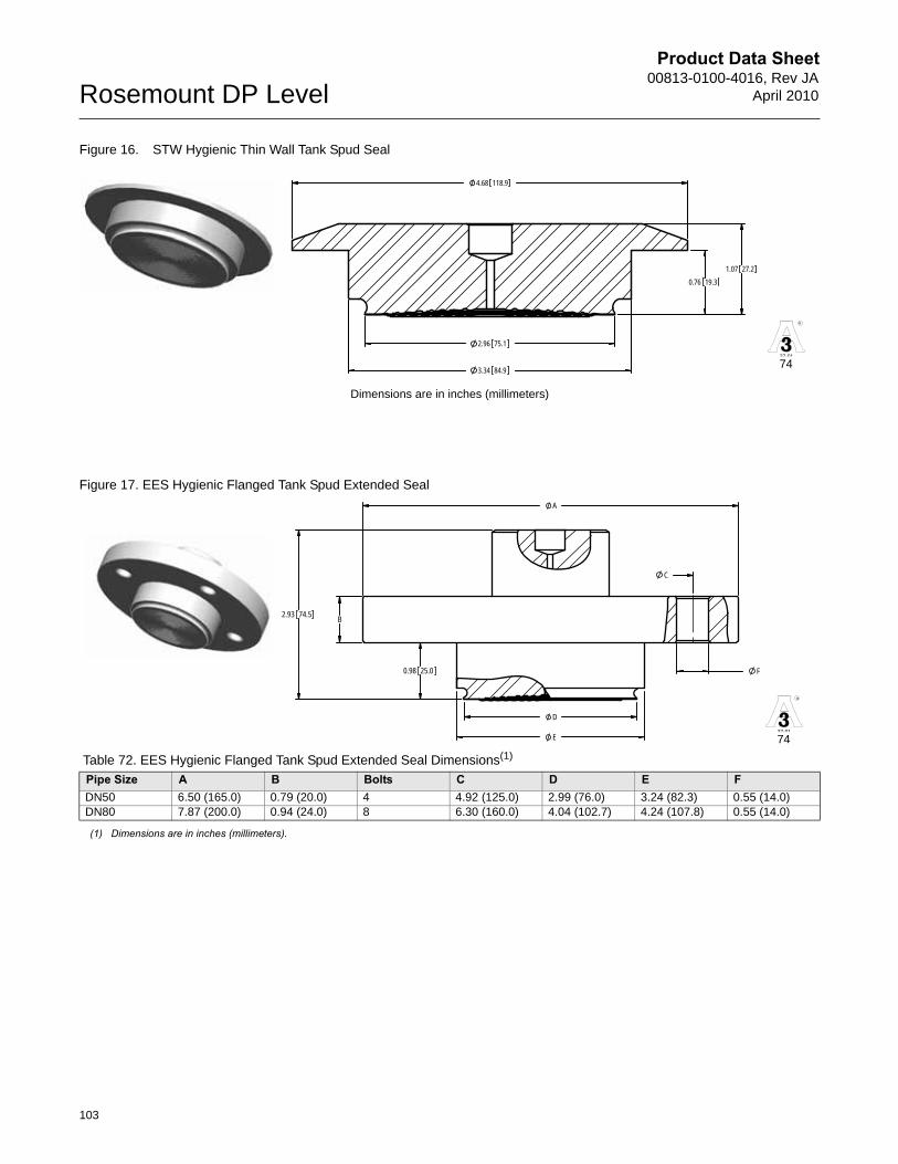
Product Data Sheet00813-0100-4016, Rev JA
April 2010Rosemount DP Level
Figure 16. STW Hygienic Thin Wall Tank Spud Seal
Figure 17. EES Hygienic Flanged Tank Spud Extended Seal
Dimensions are in inches (millimeters)
Table 72. EES Hygienic Flanged Tank Spud Extended Seal Dimensions(1)
(1) Dimensions are in inches (millimeters).
Pipe Size A B Bolts C D E FDN50 6.50 (165.0) 0.79 (20.0) 4 4.92 (125.0) 2.99 (76.0) 3.24 (82.3) 0.55 (14.0)DN80 7.87 (200.0) 0.94 (24.0) 8 6.30 (160.0) 4.04 (102.7) 4.24 (107.8) 0.55 (14.0)
R
37-01
1.07 27.20.76 19.3
2.96 75.1
3.34 84.9
4.68 118.9
74
R
37-01
C
A
F
B
0.98 25.0
D
E
2.93 74.5
74
103

Product Data Sheet00813-0100-4016, Rev JA
April 2010Rosemount DP Level
Figure 18. VCS Tri-clamp In-Line Seal
Figure 19. SVS Varivent Compatible Connection Seal
Table 73. VCS Tri-clamp In-Line Seal Dimensions(1)
(1) Dimensions are in inches (millimeters).
Pipe Size A B C D E1-in. 0.870 (22.10) 1.720 (43.69) 1.990 (50.55) 2.28 (57.9) 3.54 (90.0)1½-in. 1.370 (34.80) 1.720 (43.69) 1.990 (50.55) 2.73 (69.3) 3.54 (90.0)2-in. 1.870 (47.50) 2.220 (56.39) 2.520 (64.01) 3.19 (81.0) 3.54 (90.0)3-in. 2.870 (72.90) 3.280 (83.31) 3.580 (90.93) 4.14 (105.2) 3.54 (90.0)4-in. 3.820 (97.03) 4.350 (110.49) 4.690 (119.13) 5.06 (128.5) 3.54 (90.0)
Dimensions are in inches (millimeters)
R
37-01
E
B CA D
74
R
37-01
0.664 16.87
3.3 84
0.48 12.2
2.51 63.8 74
104
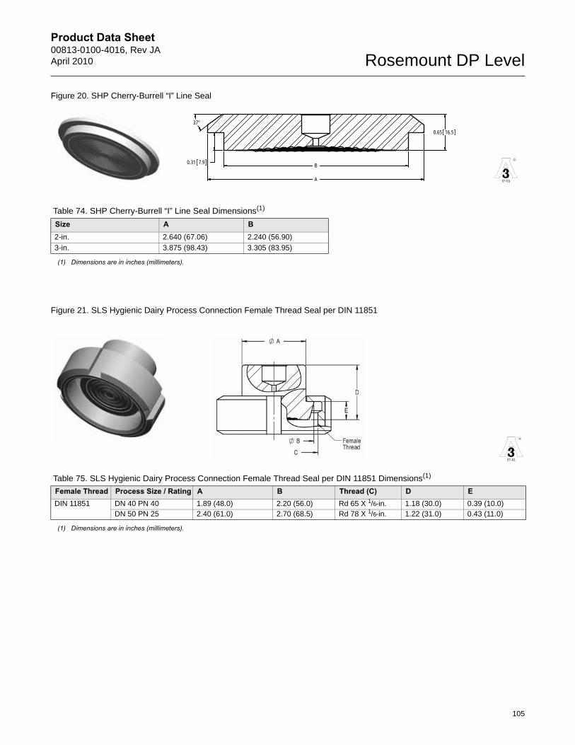
Product Data Sheet00813-0100-4016, Rev JAApril 2010 Rosemount DP Level
Figure 20. SHP Cherry-Burrell “I” Line Seal
Figure 21. SLS Hygienic Dairy Process Connection Female Thread Seal per DIN 11851
Table 74. SHP Cherry-Burrell “I” Line Seal Dimensions(1)
(1) Dimensions are in inches (millimeters).
Size A B2-in. 2.640 (67.06) 2.240 (56.90)
3-in. 3.875 (98.43) 3.305 (83.95)
Table 75. SLS Hygienic Dairy Process Connection Female Thread Seal per DIN 11851 Dimensions(1)
(1) Dimensions are in inches (millimeters).
Female Thread Process Size / Rating A B Thread (C) D EDIN 11851 DN 40 PN 40 1.89 (48.0) 2.20 (56.0) Rd 65 X 1/6-in. 1.18 (30.0) 0.39 (10.0)
DN 50 PN 25 2.40 (61.0) 2.70 (68.5) Rd 78 X 1/6-in. 1.22 (31.0) 0.43 (11.0)
R
37-01
37°
B
A
0.65 16.5
0.31 7.9
R
37-01
105
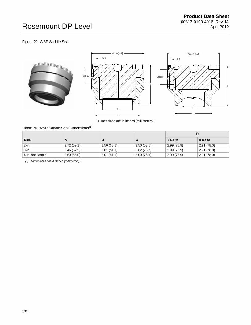
Product Data Sheet00813-0100-4016, Rev JA
April 2010Rosemount DP Level
106
Figure 22. WSP Saddle Seal
Dimensions are in inches (millimeters)
Table 76. WSP Saddle Seal Dimensions(1)
(1) Dimensions are in inches (millimeters).
Size A B C
D
6 Bolts 8 Bolts2-in. 2.72 (69.1) 1.50 (38.1) 2.50 (63.5) 2.99 (75.9) 2.91 (78.0)
3-in. 2.46 (62.5) 2.01 (51.1) 3.02 (76.7) 2.99 (75.9) 2.91 (78.0)
4-in. and larger 2.60 (66.0) 2.01 (51.1) 3.00 (76.1) 2.99 (75.9) 2.91 (78.0)
A
1.00 25.4
3.50 88.9
C
B
D
B
A
1.00 25.4
3.50 88.9
C
D
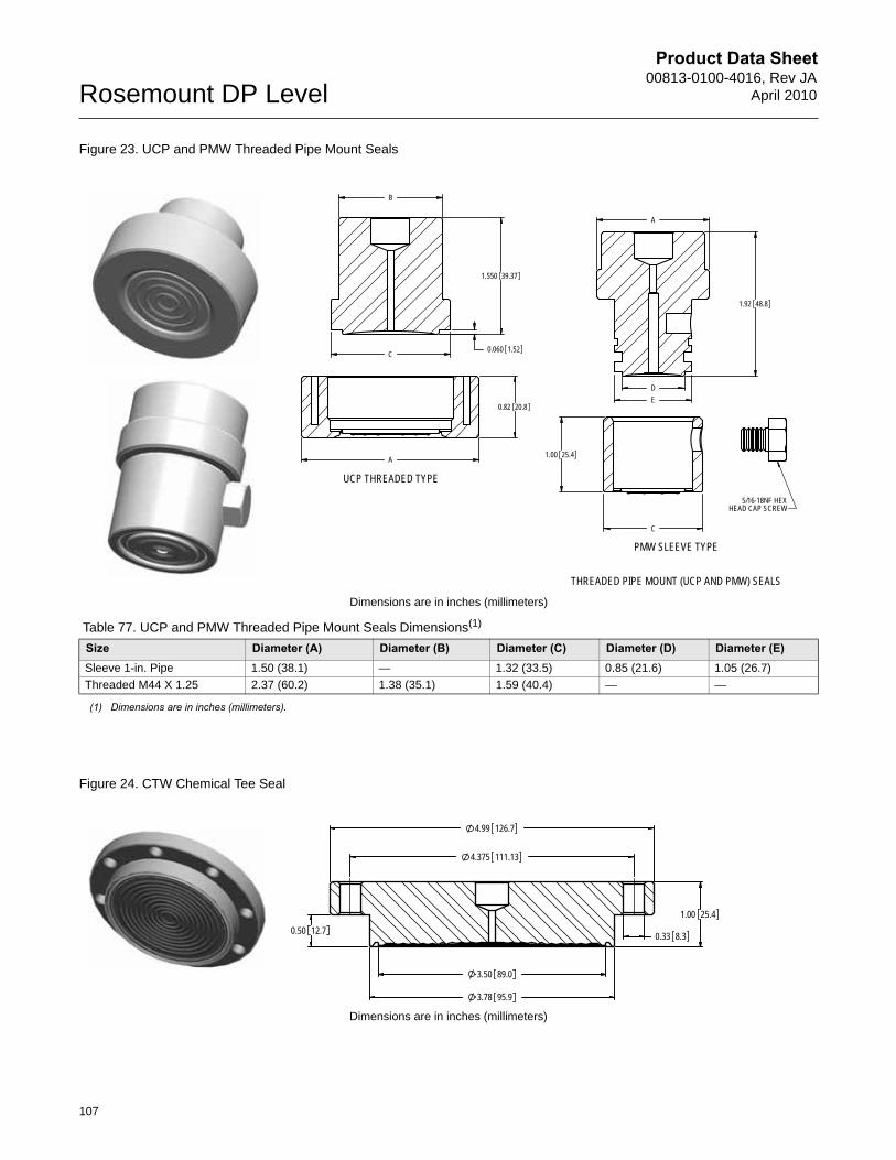
Product Data Sheet00813-0100-4016, Rev JA
April 2010Rosemount DP Level
Figure 23. UCP and PMW Threaded Pipe Mount Seals
Figure 24. CTW Chemical Tee Seal
Dimensions are in inches (millimeters)
Table 77. UCP and PMW Threaded Pipe Mount Seals Dimensions(1)
(1) Dimensions are in inches (millimeters).
Size Diameter (A) Diameter (B) Diameter (C) Diameter (D) Diameter (E)Sleeve 1-in. Pipe 1.50 (38.1) — 1.32 (33.5) 0.85 (21.6) 1.05 (26.7)
Threaded M44 X 1.25 2.37 (60.2) 1.38 (35.1) 1.59 (40.4) — —
Dimensions are in inches (millimeters)
C
B
A
1.550 39.37
0.060 1.52
0.82 20.8
1.00 25.4
A
C
1.92 48.8
ED
5/16-18NF HEXHEAD CAP SCREW
THREADED PIPE MOUNT (UCP AND PMW) SEALS
UCP THREADED TYPE
PMW SLEEVE TYPE
4.99 126.7
3.78 95.9
3.50 89.0
1.00 25.40.50 12.7 0.33 8.3
4.375 111.13
107
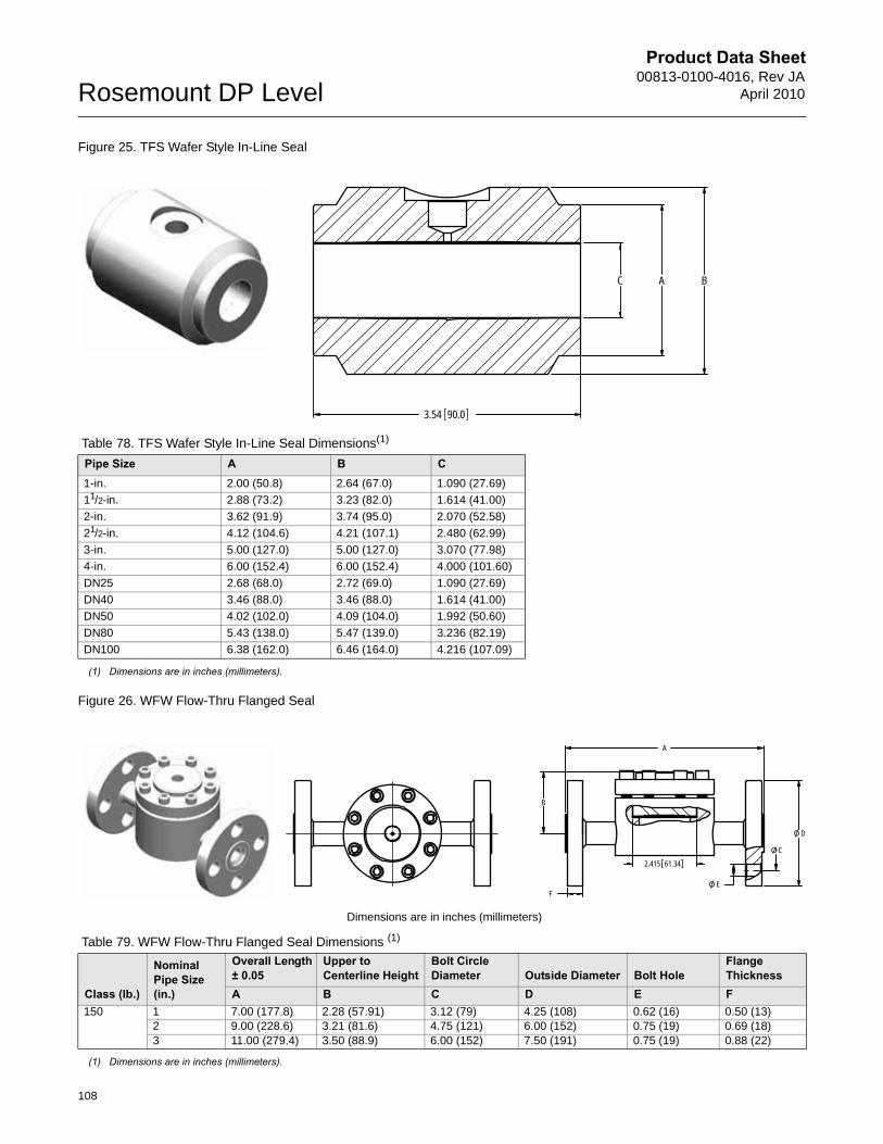
Product Data Sheet00813-0100-4016, Rev JA
April 2010Rosemount DP Level
Figure 25. TFS Wafer Style In-Line Seal
Figure 26. WFW Flow-Thru Flanged Seal
Table 78. TFS Wafer Style In-Line Seal Dimensions(1)
(1) Dimensions are in inches (millimeters).
Pipe Size A B C1-in. 2.00 (50.8) 2.64 (67.0) 1.090 (27.69)
11/2-in. 2.88 (73.2) 3.23 (82.0) 1.614 (41.00)
2-in. 3.62 (91.9) 3.74 (95.0) 2.070 (52.58)
21/2-in. 4.12 (104.6) 4.21 (107.1) 2.480 (62.99)
3-in. 5.00 (127.0) 5.00 (127.0) 3.070 (77.98)
4-in. 6.00 (152.4) 6.00 (152.4) 4.000 (101.60)
DN25 2.68 (68.0) 2.72 (69.0) 1.090 (27.69)
DN40 3.46 (88.0) 3.46 (88.0) 1.614 (41.00)
DN50 4.02 (102.0) 4.09 (104.0) 1.992 (50.60)
DN80 5.43 (138.0) 5.47 (139.0) 3.236 (82.19)
DN100 6.38 (162.0) 6.46 (164.0) 4.216 (107.09)
Dimensions are in inches (millimeters)
Table 79. WFW Flow-Thru Flanged Seal Dimensions (1)
(1) Dimensions are in inches (millimeters).
Class (lb.)
Nominal Pipe Size (in.)
Overall Length ± 0.05
Upper to Centerline Height
Bolt Circle Diameter Outside Diameter Bolt Hole
Flange Thickness
A B C D E F150 1 7.00 (177.8) 2.28 (57.91) 3.12 (79) 4.25 (108) 0.62 (16) 0.50 (13)
2 9.00 (228.6) 3.21 (81.6) 4.75 (121) 6.00 (152) 0.75 (19) 0.69 (18)3 11.00 (279.4) 3.50 (88.9) 6.00 (152) 7.50 (191) 0.75 (19) 0.88 (22)
C A B
3.54 90.0
C
E
D
2.415 61.34
F
A
B
108
Product Data Sheet00813-0100-4016, Rev JAApril 2010 Rosemount DP Level
109
Product Data Sheet00813-0100-4016, Rev JA
April 2010Rosemount DP Level
Standard Terms and Conditions of Sale can be found at www.rosemount.com\terms_of_saleThe Emerson logo is a trade mark and service mark of Emerson Electric Co. Rosemount , Instrument Toolkit, and the Rosemount logotype are registerd trademarks of Rosemount Inc.Coplanar and Tuned-System Assemblies are trademarks of Rosemount Inc.Instrument Toolkit is a registered trademark of Emerson Process Management.Varivent is a registered trademark of Tuchenhagen GmbH.Viton and Teflon are registered trademarks of E.I. duPont de Nemours & Co.Syltherm, and D.C. are regiastered trademarks of Dow Corning Corp.Tri-Clamp is a registered trademark of Tri-Clover, Inc. of the Alfa-Laval Group.Thermo-Tork is a registered trademark of Armstron World Industries, Inc.
Rosemount Level SolutionsEmerson provides a complete range of Rosemount products for level measurement applications.
Pressure – Level or Interface MeasurementEmerson has a complete line of Rosemount pressure transmitters and remote seals for measuring level or interfaces in liquid applications. Optimize performance with direct mount, Tuned Seal systems:
• Rosemount 3051S_L, 3051L, and 2051L Liquid Level Transmitters
• Rosemount 1199 Remote Diaphragm Seals with direct mount or capillary connections
Vibrating Fork Switches – Point Level DetectionThe Rosemount 2100 Series is developed for reliable point level detection of liquids and consists of:
• Rosemount 2110 Compact Vibrating Fork Liquid Level Switch
• Rosemount 2120 Full-featured Vibrating Fork Liquid Level Switch
Guided Wave Radar – Level and Interface MeasurementMultivariable, loop-powered Guided Wave Radar transmitters with a wide range of probe styles to fit different liquids and solids applications. The product line consists of:
• Rosemount 3300 Series – Versatile and easy-to-use transmitter with proven reliability
• Rosemount 5300 Series – Accurate, superior performance transmitter with FOUNDATION™ fieldbus support
Non-contacting Radar – Level MeasurementThe Rosemount non-contacting radar family consists of:
• Rosemount 5400 Series Transmitters – Loop-powered superior performance transmitter with a wide range of antennas, for liquid level measurement in most applications and process conditions
• Rosemount 5600 Series Transmitters – Power of 4-wire give maximum sensitivity and performance for solids, challenging reactors, rapid level changes and excessive process conditions.
Non-contacting Ultrasonic – Level MeasurementThe Rosemount 3100 Series ultrasonic level transmitters provide continuous non-contacting level measurement of liquids. The range consisits of:
• Rosemount 3101 for simple continuous level measurement
• Rosemount 3102 for continuous measurement with two integral relays for local control functionality
• Rosemount 3105 Intrinsically safe certified version for hazardous areas
00813-0100-4016 Rev JA, 4/10
Neobee M-20 is a registered trademark of Stepan Chemical Co. Windows is a registered trademark of Microsoft Corp.Cherry-Burrell is a trademark of the United Dominion Industries.The 3-A symbol is a registered trademark of the 3-A Sanitary Standards Symbol Council.
Many other special order transmitter/seal configurations, materials and fill fluids are available that are not covered in this document. Contact your Rosemount representative or consult factory for additional information.
Emerson Process Management Blegistrasse 23P.O. Box 1046CH 6341 BaarSwitzerlandTel +41 (0) 41 768 6111Fax +41 (0) 41 768 6300
Emerson Process Management Asia Pacific Pte Ltd1 Pandan CrescentSingapore 128461Tel +65 6777 8211Fax +65 6777 0947Service Support Hotline : +65 6770 8711Email : [email protected]
Emerson Process ManagementRosemount Measurement8200 Market BoulevardChanhassen MN 55317 USATel (USA) 1 800 999 9307Tel (International) +1 952 906 8888Fax +1 952 949 7001
Emerson FZEP.O. Box 17033Jebel Ali Free ZoneDubai UAETel +971 4 811 8100Fax +971 4 886 5465