Embed Size (px)
Citation preview
4 ROTATIONAL MOLDING MACHINES
4.0 Introduction
The basic principle of rotational molding involves heating plastic inside ahollow shell-like mold, which is rotated so that the melted plastic forms acoating on the inside surface of the mold. The rotating mold is then cooledso that the plastic solidifies to the desired shape and the molded part isremoved. There are many methods that can be used to achieve the essen-tial requirements of mold rotation, heating, and cooling. It has been esti-mated that about 40% of the rotational molding machines in use in theU.S. are home-built. Of the remaining 60%, about 70% are more than tenyears old, and 40% are more than twenty years old. The percentage ofhome-built machines is even higher in some other parts of the world, butthere is a move toward the purchase of new machines as molders start toconcentrate on their core business in order to survive in very competitivemarkets. The data acquisition systems and process control on commercialmachines also make them attractive and compare very favorably withwhat is available in competing technologies such as blow molding, ther-moforming, and injection molding.
Most people with general engineering skills tend to take the view thata rotational molding machine is not a complex piece of equipment. Whilefew individuals or molding companies would contemplate building a blowmolding machine or an injection molding machine, there has been no suchreluctance to build rotational molding machines. This has worked well forsome small companies in that it has allowed them to meet internal needsor satisfy a local niche market, but this do-it-yourself approach has alsoharmed the image of the industry. Home-built machines by their natureoften do not have much investment in safety features or aesthetics andare highly individual in appearance and performance.
The build vs. buy strategy depends on many circumstances and quiteoften relates to the nature of the business and the local market. The unique-ness of the part can dictate this decision. A company may be in an engineer-ing business not directly involved in plastics, but it currently purchases hollowplastic parts. It may take a business decision to manufacture these in-house.From its general engineering expertise such a company can be quite capableof making a simple machine to rotate, heat, and cool a mold for making the
111
112 Rotational Molding Technology
parts. The machine will be product specific but will be as good or better thananything that the company could buy for its needs, and will certainly be lessexpensive.
Another common scenario is where a company manufactures productsfrom fiber-reinforced plastic (FRP) and/or thermoformed plastic, but desiresto broaden its product range. Rotational molding is a closely allied manufac-turing method and from the company�s expertise in working with plastics, it isno great challenge for it to make a rotational molding machine for new prod-ucts that are similar to its existing lines, in order to broaden its customer base.There are also many examples of individuals or companies that use tanks orcontainers for dispensing or storing insecticides and chemicals, and they de-cide to manufacture their own storage containers because these are regardedas being too expensive or have limited availability. Or there may be confiden-tiality associated with the product. If the part being rotationally molded re-quires special polymers, special treatment, or special processing conditions,the logical business decision may be to construct a special machine specifi-cally for that particular part.
In circumstances such as those described above, it may well haveproved advantageous to build rotational molding equipment in-house. Thetrend in the industry is, however, toward high technology with more so-phisticated molds, improved machine controls, internal cooling, and moldpressurization. Commercial machines will undoubtedly offer economicadvantages in terms of faster cycle times and more economic operation,so that it will be difficult for molders to remain in competitive marketsectors without having this type of equipment.
Full details on the types of machines used by rotational molders aregiven in other sources.1�3 In this book the emphasis is on the conceptsand principles of rotational molding and so this chapter gives an overviewof the types of machines that are available, and concentrates on the tech-nology of the equipment.
4.1 Types of Rotational Molding Machines
Since rotationally molded parts range in volume from 0.05 liters to morethan 10,000 liters, generalization on machine types is difficult. The com-mon aspects of the process are that the mold and its contents need to berotated, heated, and cooled. There also needs to be a convenient opportunity
Rotational Molding Machines 113
to remove the end product from the mold and put a fresh charge of plasticinto the mold. Furthermore, while the servicing station is always required,not all machines need ovens or cooling stations. If a reactive liquid suchas epoxy or catalyzed unsaturated polyester resin is used as the polymer,formation of the monolithic structure occurs without external heat and theshape of the end product is retained without the need for cooling. Further-more, in some instances, the heating cycle is so long that cooling can beachieved simply by allowing the mold to rotate in quiescent room air.
Nevertheless, there are some basic types of commercial rotational mold-ing machines that are common across the industry. The varieties of machinesthat are available are described below.
4.1.1 Rock-and-Roll Machines
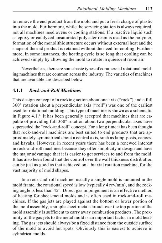
This design concept of a rocking action about one axis (�rock�) and a full360° rotation about a perpendicular axis (�roll�) was one of the earliestused for rotational molding. This type of machine is shown as a schematicin Figure 4.1.4 It has been generally accepted that machines that are ca-pable of providing full 360° rotation about two perpendicular axes havesuperseded the �rock-and-roll� concept. For a long time it has been thoughtthat rock-and-roll machines are best suited to end products that are ap-proximately symmetrical about a central axis, such as lamp-posts, canoes,and kayaks. However, in recent years there has been a renewed interestin rock-and-roll machines because they offer simplicity in design and havethe major advantage that it is easier to get services to and from the mold.It has also been found that the control over the wall thickness distributioncan be just as good as that achieved on a biaxial rotation machine, for thevast majority of mold shapes.
In a rock-and-roll machine, usually a single mold is mounted in themold frame, the rotational speed is low (typically 4 rev/min), and the rock-ing angle is less than 45°. Direct gas impingement is an effective methodof heating for sheet-metal molds and is often used in rock-and-roll ma-chines. If the gas jets are played against the bottom or lower portion ofthe mold assembly, a simple sheet-metal shroud over the top portion of themold assembly is sufficient to carry away combustion products. The prox-imity of the gas jets to the metal mold is an important factor in mold heat-ing. The gas jets should always be a fixed distance from the outside surfaceof the mold to avoid hot spots. Obviously this is easiest to achieve incylindrical molds.
114 Rotational Molding Technology
Figure 4.1 Typical rock-and-roll machine, used with permission ofThe Queen�s University, Belfast
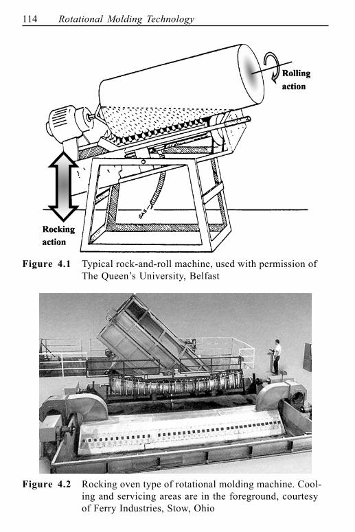
Figure 4.2 Rocking oven type of rotational molding machine. Cool-ing and servicing areas are in the foreground, courtesyof Ferry Industries, Stow, Ohio
Rotational Molding Machines 115
In the rocking oven machine the mold is surrounded by an oven, heatedby hot air, and the oven rocks with the mold as shown in Figure 4.2. Therocking oven must contain appropriate burner assemblies, ducting and blow-ers, as well as an adequate shroud. In some cases the mold assembly is mountedon a rail carriage, so that it can be rolled from the oven chamber to the coolingarea. Frequently the cooling area is also the servicing station. For smallerrock-and-roll machines, the oven can be shuttled, or crane-lifted, over themold assembly. For larger machines, the oven is stationary and the mold as-sembly is moved into it through a single door. Commercial rotational moldingmachinery builders do manufacture rock-and-roll machines, but most rock-and-roll machines are home-built.
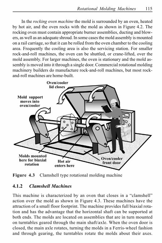
Figure 4.3 Clamshell type rotational molding machine
4.1.2 Clamshell Machines
This machine is characterized by an oven that closes in a �clamshell�action over the mold as shown in Figure 4.3. These machines have theattraction of a small floor footprint. The machine provides full biaxial rota-tion and has the advantage that the horizontal shaft can be supported atboth ends. The molds are located on assemblies that are in turn mountedon turntables geared through the main shaft/axle. When the oven door isclosed, the main axle rotates, turning the molds in a Ferris-wheel fashionand through gearing, the turntables rotate the molds about their axes.
116 Rotational Molding Technology
Heated air is circulated through the cabinet until the appropriate polymertemperature is achieved, then cooling occurs by cooled air and/or watermist. At the completion of the cooling cycle, the cabinet door opens with abook action, the molds are opened, and the parts are removed. The moldsare then cleaned, inspected, and refilled with polymer and the next cyclebegins. In some designs of clamshell machines, the molds leave the ovenchamber at the end of the heating phase so that cooling can take placeexternally. This makes the oven chamber free to receive another set ofmolds while the previous set are being cooled and serviced.
4.1.3 Vertical Machines
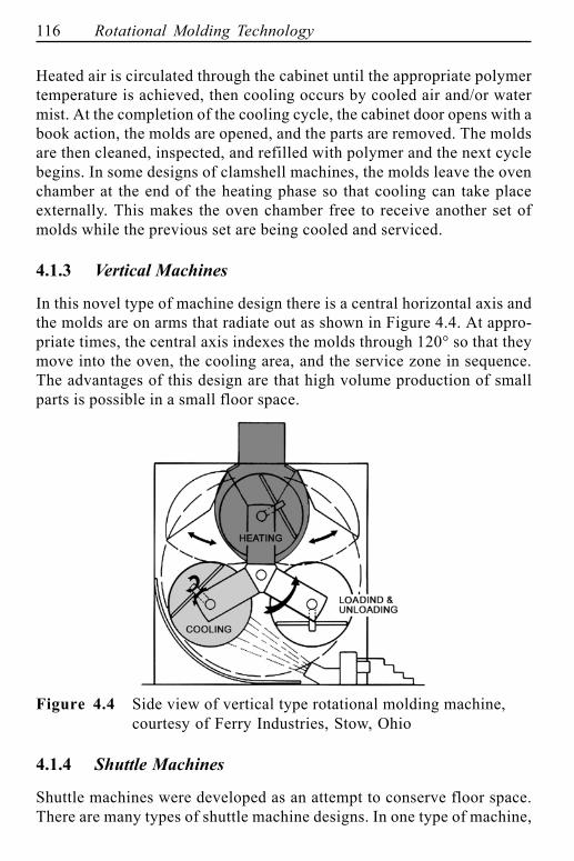
In this novel type of machine design there is a central horizontal axis andthe molds are on arms that radiate out as shown in Figure 4.4. At appro-priate times, the central axis indexes the molds through 120° so that theymove into the oven, the cooling area, and the service zone in sequence.The advantages of this design are that high volume production of smallparts is possible in a small floor space.
Figure 4.4 Side view of vertical type rotational molding machine,courtesy of Ferry Industries, Stow, Ohio
4.1.4 Shuttle Machines
Shuttle machines were developed as an attempt to conserve floor space.There are many types of shuttle machine designs. In one type of machine,
Rotational Molding Machines 117
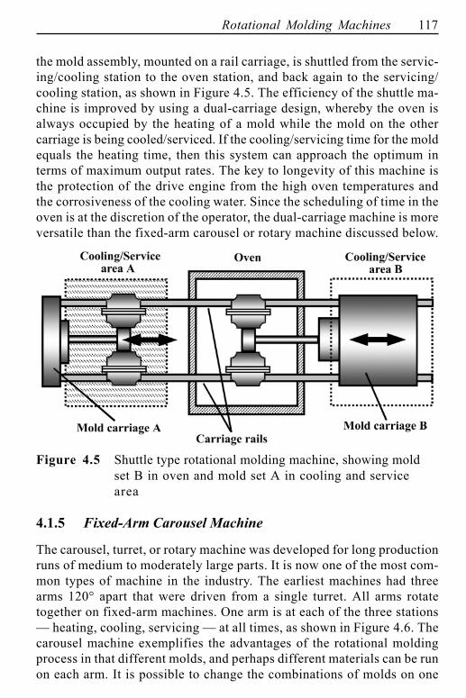
the mold assembly, mounted on a rail carriage, is shuttled from the servic-ing/cooling station to the oven station, and back again to the servicing/cooling station, as shown in Figure 4.5. The efficiency of the shuttle ma-chine is improved by using a dual-carriage design, whereby the oven isalways occupied by the heating of a mold while the mold on the othercarriage is being cooled/serviced. If the cooling/servicing time for the moldequals the heating time, then this system can approach the optimum interms of maximum output rates. The key to longevity of this machine isthe protection of the drive engine from the high oven temperatures andthe corrosiveness of the cooling water. Since the scheduling of time in theoven is at the discretion of the operator, the dual-carriage machine is moreversatile than the fixed-arm carousel or rotary machine discussed below.
Figure 4.5 Shuttle type rotational molding machine, showing moldset B in oven and mold set A in cooling and servicearea
4.1.5 Fixed-Arm Carousel Machine
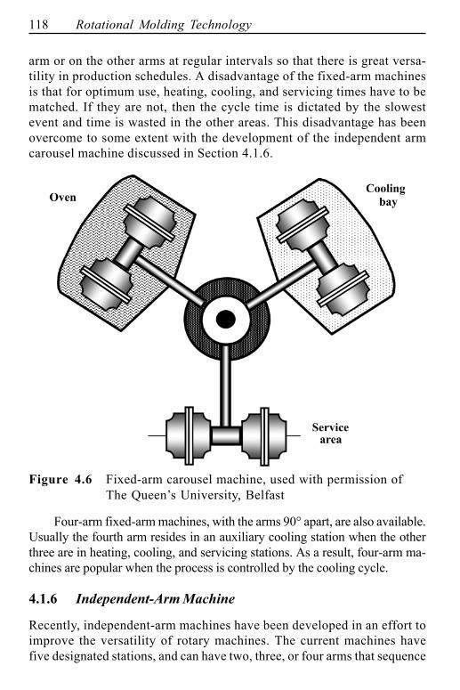
The carousel, turret, or rotary machine was developed for long productionruns of medium to moderately large parts. It is now one of the most com-mon types of machine in the industry. The earliest machines had threearms 120° apart that were driven from a single turret. All arms rotatetogether on fixed-arm machines. One arm is at each of the three stations� heating, cooling, servicing � at all times, as shown in Figure 4.6. Thecarousel machine exemplifies the advantages of the rotational moldingprocess in that different molds, and perhaps different materials can be runon each arm. It is possible to change the combinations of molds on one
118 Rotational Molding Technology
arm or on the other arms at regular intervals so that there is great versa-tility in production schedules. A disadvantage of the fixed-arm machinesis that for optimum use, heating, cooling, and servicing times have to bematched. If they are not, then the cycle time is dictated by the slowestevent and time is wasted in the other areas. This disadvantage has beenovercome to some extent with the development of the independent armcarousel machine discussed in Section 4.1.6.
Figure 4.6 Fixed-arm carousel machine, used with permission ofThe Queen�s University, Belfast
Four-arm fixed-arm machines, with the arms 90° apart, are also available.Usually the fourth arm resides in an auxiliary cooling station when the otherthree are in heating, cooling, and servicing stations. As a result, four-arm ma-chines are popular when the process is controlled by the cooling cycle.
4.1.6 Independent-Arm Machine
Recently, independent-arm machines have been developed in an effort toimprove the versatility of rotary machines. The current machines havefive designated stations, and can have two, three, or four arms that sequence
Rotational Molding Machines 119
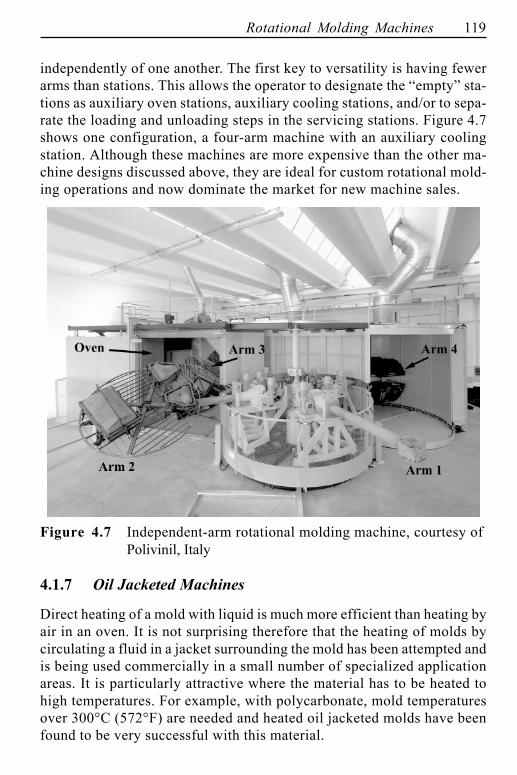
independently of one another. The first key to versatility is having fewerarms than stations. This allows the operator to designate the �empty� sta-tions as auxiliary oven stations, auxiliary cooling stations, and/or to sepa-rate the loading and unloading steps in the servicing stations. Figure 4.7shows one configuration, a four-arm machine with an auxiliary coolingstation. Although these machines are more expensive than the other ma-chine designs discussed above, they are ideal for custom rotational mold-ing operations and now dominate the market for new machine sales.
Figure 4.7 Independent-arm rotational molding machine, courtesy ofPolivinil, Italy
4.1.7 Oil Jacketed Machines
Direct heating of a mold with liquid is much more efficient than heating byair in an oven. It is not surprising therefore that the heating of molds bycirculating a fluid in a jacket surrounding the mold has been attempted andis being used commercially in a small number of specialized applicationareas. It is particularly attractive where the material has to be heated tohigh temperatures. For example, with polycarbonate, mold temperaturesover 300°C (572°F) are needed and heated oil jacketed molds have beenfound to be very successful with this material.
120 Rotational Molding Technology
The disadvantage of such systems is that it is difficult to avoid oil leaks inthe rotating joints. When this happens there are unpleasant fumes and theplastic can become contaminated. To alleviate such problems, heated saltshave been used in the jacketed mold. However, such machines are rarelyused commercially.
In recent years, there has been a renewed interest in direct mold heatingbecause not only is the liquid heating very efficient, but the absence of anoven means that it is easy to get process control devices close to the moldwithout worrying about overheating of sensitive electrical equipment.
4.1.8 Electrically Heated Machines
One of the most innovative types of rotational molding machine to haveemerged in recent years is an electrically heated system in which a net-work of fine electrical wires are embedded in a cast, nonmetallic mold.5�7
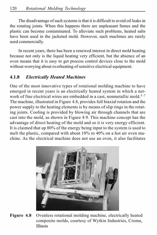
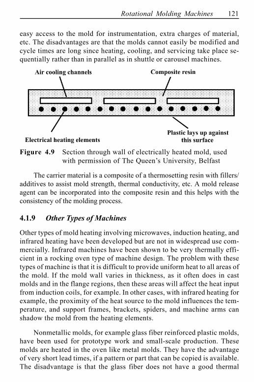
The machine, illustrated in Figure 4.8, provides full biaxial rotation and thepower supply to the heating elements is by means of slip rings in the rotat-ing joints. Cooling is provided by blowing air through channels that arecast into the mold, as shown in Figure 4.9. This machine concept has theadvantage of direct heating of the mold and so it is very energy efficient.It is claimed that up 80% of the energy being input to the system is used tomelt the plastic, compared with about 10% to 40% on a hot air oven ma-chine. As the electrical machine does not use an oven, it also facilitates
Figure 4.8 Ovenless rotational molding machine, electrically heatedcomposite molds, courtesy of Wytkin Industries, Croma,Illinois
Rotational Molding Machines 121
easy access to the mold for instrumentation, extra charges of material,etc. The disadvantages are that the molds cannot easily be modified andcycle times are long since heating, cooling, and servicing take place se-quentially rather than in parallel as in shuttle or carousel machines.
Figure 4.9 Section through wall of electrically heated mold, usedwith permission of The Queen�s University, Belfast
The carrier material is a composite of a thermosetting resin with fillers/additives to assist mold strength, thermal conductivity, etc. A mold releaseagent can be incorporated into the composite resin and this helps with theconsistency of the molding process.
4.1.9 Other Types of Machines
Other types of mold heating involving microwaves, induction heating, andinfrared heating have been developed but are not in widespread use com-mercially. Infrared machines have been shown to be very thermally effi-cient in a rocking oven type of machine design. The problem with thesetypes of machine is that it is difficult to provide uniform heat to all areas ofthe mold. If the mold wall varies in thickness, as it often does in castmolds and in the flange regions, then these areas will affect the heat inputfrom induction coils, for example. In other cases, with infrared heating forexample, the proximity of the heat source to the mold influences the tem-perature, and support frames, brackets, spiders, and machine arms canshadow the mold from the heating elements.
Nonmetallic molds, for example glass fiber reinforced plastic molds,have been used for prototype work and small-scale production. Thesemolds are heated in the oven like metal molds. They have the advantageof very short lead times, if a pattern or part that can be copied is available.The disadvantage is that the glass fiber does not have a good thermal
122 Rotational Molding Technology
conductivity and suffers embrittlement at elevated oven temperatures.
4.2 Machine Design Considerations
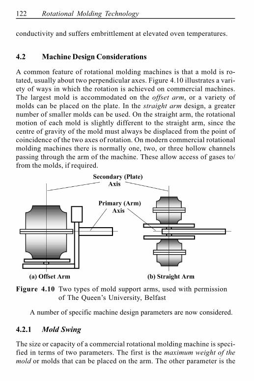
A common feature of rotational molding machines is that a mold is ro-tated, usually about two perpendicular axes. Figure 4.10 illustrates a vari-ety of ways in which the rotation is achieved on commercial machines.The largest mold is accommodated on the offset arm, or a variety ofmolds can be placed on the plate. In the straight arm design, a greaternumber of smaller molds can be used. On the straight arm, the rotationalmotion of each mold is slightly different to the straight arm, since thecentre of gravity of the mold must always be displaced from the point ofcoincidence of the two axes of rotation. On modern commercial rotationalmolding machines there is normally one, two, or three hollow channelspassing through the arm of the machine. These allow access of gases to/from the molds, if required.
Figure 4.10 Two types of mold support arms, used with permissionof The Queen�s University, Belfast
A number of specific machine design parameters are now considered.
4.2.1 Mold Swing
The size or capacity of a commercial rotational molding machine is speci-fied in terms of two parameters. The first is the maximum weight of themold or molds that can be placed on the arm. The other parameter is the
Rotational Molding Machines 123
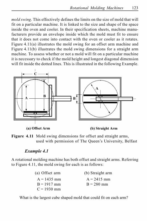
mold swing. This effectively defines the limits on the size of mold that willfit on a particular machine. It is linked to the size and shape of the spaceinside the oven and cooler. In their specification sheets, machine manu-facturers provide an envelope inside which the mold must fit to ensurethat it does not come into contact with the oven or cooler as it rotates.Figure 4.11(a) illustrates the mold swing for an offset arm machine andFigure 4.11(b) illustrates the mold swing dimensions for a straight armmachine. To assess whether or not a mold will fit on a particular machineit is necessary to check if the mold height and longest diagonal dimensionwill fit inside the dotted lines. This is illustrated in the following Example.
Figure 4.11 Mold swing dimensions for offset and straight arms,used with permission of The Queen�s University, Belfast
Example 4.1
A rotational molding machine has both offset and straight arms. Referringto Figure 4.11, the mold swing for each is as follows:
(a) Offset arm (b) Straight armA = 1435 mm A = 2415 mmB = 1917 mm B = 280 mmC = 1930 mm
What is the largest cube shaped mold that could fit on each arm?
124 Rotational Molding Technology
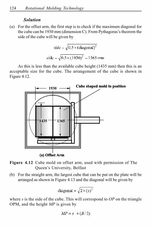
Solution(a) For the offset arm, the first step is to check if the maximum diagonal for
the cube can be 1930 mm (dimension C). From Pythagoras�s theorem theside of the cube will be given by
As this is less than the available cube height (1435 mm) then this is anacceptable size for the cube. The arrangement of the cube is shown inFigure 4.12.
Figure 4.12 Cube mold on offset arm, used with permission of TheQueen�s University, Belfast
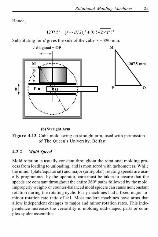
(b) For the straight arm, the largest cube that can be put on the plate will bearranged as shown in Figure 4.13 and the diagonal will be given by
where s is the side of the cube. This will correspond to OP on the triangleOPM, and the height MP is given by
Rotational Molding Machines 125
Hence,
Substituting for B gives the side of the cube, s = 890 mm.
Figure 4.13 Cube mold swing on straight arm, used with permissionof The Queen�s University, Belfast
4.2.2 Mold Speed
Mold rotation is usually constant throughout the rotational molding pro-cess from loading to unloading, and is monitored with tachometers. Whilethe minor (plate/equatorial) and major (arm/polar) rotating speeds are usu-ally programmed by the operator, care must be taken to ensure that thespeeds are constant throughout the entire 360° paths followed by the mold.Improperly weight- or counter-balanced mold spiders can cause nonconstantrotation during the rotating cycle. Early machines had a fixed major-to-minor rotation rate ratio of 4:1. Most modern machines have arms thatallow independent changes to major and minor rotation rates. This inde-pendence increases the versatility in molding odd-shaped parts or com-plex spider assemblies.
126 Rotational Molding Technology
4.2.3 Speed Ratio
During rotational molding, the speeds of rotation are slow and the plasticeffectively resides in the bottom of the mold. The thickness of the coatingof the plastic on the mold wall depends on how regularly each point on themold surface dips into the powder pool. The speed of rotation and, in abiaxial rotation machine, the ratio of the speeds about the two axes have amajor influence on the thickness distribution of the plastic on the mold.
It should be noted that the actual speeds of the arm and plate, and theirratio, are most important. As the minor axis drive shaft is often inside themajor axis drive shaft, the minor axis speed reading on the molding machinemay be higher than the major (arm) speed. The actual (relative) speed of theminor axis is lower than the major (arm) speed because it is given by thedifference between the machine readings for the minor and major axes. TheSpeed Ratio (arm/plate) is therefore often defined as
(4.1)
Thus if the minor axis speed reading on the machine is 15 rpm and themajor axis speed is 12 rpm, then the Speed Ratio (arm/plate speeds) is4:1, which is a common ratio.
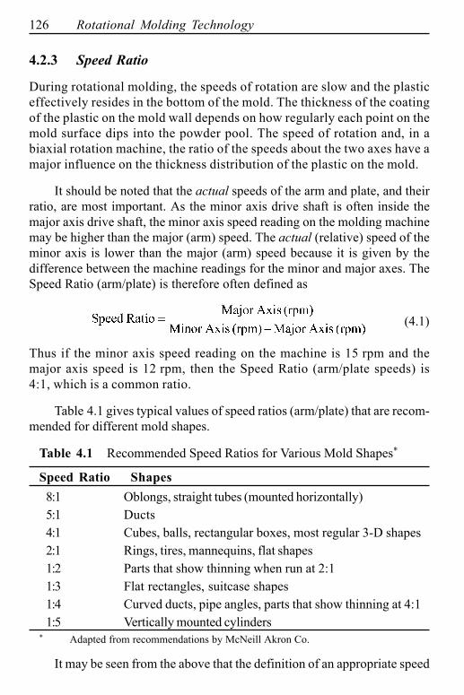
Table 4.1 gives typical values of speed ratios (arm/plate) that are recom-mended for different mold shapes.
Table 4.1 Recommended Speed Ratios for Various Mold Shapes*
Speed Ratio Shapes8:1 Oblongs, straight tubes (mounted horizontally)5:1 Ducts4:1 Cubes, balls, rectangular boxes, most regular 3-D shapes2:1 Rings, tires, mannequins, flat shapes1:2 Parts that show thinning when run at 2:11:3 Flat rectangles, suitcase shapes1:4 Curved ducts, pipe angles, parts that show thinning at 4:11:5 Vertically mounted cylinders
* Adapted from recommendations by McNeill Akron Co.
It may be seen from the above that the definition of an appropriate speed
Rotational Molding Machines 127
ratio for a particular product is not a precise science. It can depend on factorsother than the speed ratio. These include the position of the mold relative tothe major and minor axes, and the extent to which the heat source has accessto all surfaces of the mold. Modern simulation programs attempt to allow forall these factors and these will be described in more detail in later chapters.
4.3 The Oven
The objective of the first step in rotational molding is to elevate the poly-mer to temperatures where powder particles stick together, coalesce orsinter, then densify into a monolithic liquid layer adhering to the mold wall.For nearly all commercial processes, room temperature powder is intro-duced to the hollow metal mold that is also essentially at room tempera-ture. This structure is then immersed in a fluid medium that has atemperature that is sufficiently high to allow the metal mold and powderto increase in temperature to the sinter-densification temperature range.
There are three modes of heat transfer between the cool mold/polymerand the hot medium: conduction, convection, and radiation.
Conduction: This mode of heat transfer involves solid-solid contact. It isone way that energy is transmitted from the mold inner surface, throughthe mold, to the rotating powder, and into the sinter-melt residing on themold surface. However, it is not a means of heating the mold/powdermass to the molding temperature.
Radiation: This is electromagnetic energy interchange between a hotsource and a cool sink. There is no physical contact between the sourceand sink. As a result, surfaces must see each other to achieve radiantenergy interchange. Plates and wires are common methods of producingradiant energy. Although radiant energy transmission is the common wayof heating plastic sheet in thermoforming, radiation has not been usedextensively in rotational molding. The primary reason for this is that thecomplex shapes of molds and mounting apparatus are not amenable touniform energy interchange.
Convection: This involves fluid-solid contact and it is the common methodof heating (and cooling) for rotational molding. Heated fluids can be easilydirected over all surfaces of the molds. Some of the fluids used in rota-tional molding are air, combustion gas products, steam, hot water, oil, and
128 Rotational Molding Technology
molten salts. Liquids such as water, oil and molten salts, and steam areusually confined in channels or pipes that are imbedded or fastened againstthe mold surface. For atmospheric gases such as air, combustion gasproducts, and occasionally steam, the molds are immersed in the gas flow.The rate of heat addition to the mold/polymer system is defined by theheat flux, q:
(4.2)
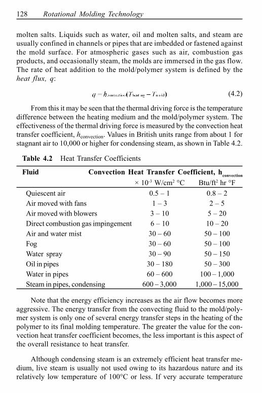
From this it may be seen that the thermal driving force is the temperaturedifference between the heating medium and the mold/polymer system. Theeffectiveness of the thermal driving force is measured by the convection heattransfer coefficient, hconvection. Values in British units range from about 1 forstagnant air to 10,000 or higher for condensing steam, as shown in Table 4.2.
Table 4.2 Heat Transfer Coefficients
Fluid Convection Heat Transfer Coefficient, hconvection
× 10-3 W/cm2 °C Btu/ft2 hr °FQuiescent air 0.5 � 1 0.8 � 2Air moved with fans 1 � 3 2 � 5Air moved with blowers 3 � 10 5 � 20Direct combustion gas impingement 6 � 10 10 � 20Air and water mist 30 � 60 50 � 100Fog 30 � 60 50 � 100Water spray 30 � 90 50 � 150Oil in pipes 30 � 180 50 � 300Water in pipes 60 � 600 100 � 1,000Steam in pipes, condensing 600 � 3,000 1,000 � 15,000
Note that the energy efficiency increases as the air flow becomes moreaggressive. The energy transfer from the convecting fluid to the mold/poly-mer system is only one of several energy transfer steps in the heating of thepolymer to its final molding temperature. The greater the value for the con-vection heat transfer coefficient becomes, the less important is this aspect ofthe overall resistance to heat transfer.
Although condensing steam is an extremely efficient heat transfer me-dium, live steam is usually not used owing to its hazardous nature and itsrelatively low temperature of 100°C or less. If very accurate temperature
Rotational Molding Machines 129
control is required, for example, for thermally sensitive polymers such as PVCor reactive polymers such as nylon, special double-wall molds are used, asdescribed earlier. Hot oil or combustion gases are circulated in the mold cav-ity. The complexity of the rotating couplings adds to the cost of this option andrestricts its use to very specialized applications.
Combustion of natural gas and air mixture yields combustion productshaving temperatures of 700°C (1292°F) to perhaps 800°C (1472°F). Directflame impingement can be used if the mold is of thick-walled carbon or high-grade stainless steel and if there is no risk of overheating or thermally degrad-ing the polymer. When aluminum molds are used and/or when the polymer isthermally sensitive for whatever reason, the combustion products are used toheat the air indirectly, which in turn is blown against the mold and frameworksurfaces. Forced convection or high-velocity circulation and recirculation ofoven air provides the most effective mode of air heat transfer. Air velocitiesover mold surfaces should be at least 1.5 m/s (5 ft/s) in order to obtain ad-equate heat transfer. Nevertheless, forced air convection heat transfer coef-ficient values are typically less than those for other modes of convection heattransfer. The traditional heating device is an insulated sheet-metal oven hav-ing insulated doors, a gas combustion region, and high-velocity blowers orfans to recirculate the air inside the oven.
4.3.1 Oven Design
Electrically generated infrared heat has been used as a primary heatingmethod, but by far the most common method of heating is by means of gascombustion. The key to improved energy efficiency lies in adequate insu-lation of the oven, optimum burner design, and energy conservation duringmold ingress and egress. The following sections consider some aspects ofoven design.
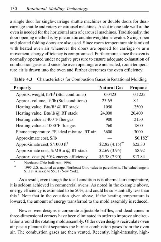
Gas Combustion. Two gaseous fuels are commonly used to produce heatin rotational molding ovens � natural gas and propane. The heating val-ues for these are given in Table 4.3. It is estimated that combustion effi-ciency is about 50%. As an example, for a machine having a 115 inch armswing, the oven capacity is 4.5 MBtu/hr. The 1995�1996 cost to operatethis oven in Northeast Ohio on natural gas was about $22/hr and in up-state New York, about $28/hr.
As mentioned above, the conventional oven for commercial rotationalmolding machines is a double-walled, heavily insulated sheet-metal box having
130 Rotational Molding Technology
a single door for single-carriage shuttle machines or double doors for dual-carriage shuttle and rotary or carousel machines. A slot in one side wall of theoven is needed for the horizontal arm of carousel machines. Traditionally, thedoor opening method is by pneumatic counterweighted elevator. Swing-openand pleated folding doors are also used. Since room temperature air is mixedwith heated oven air whenever the doors are opened for carriage or armmovement, energy efficiency is compromised. Furthermore, since the oven isnormally operated under negative pressure to ensure adequate exhaustion ofcombustion gases and since the oven openings are not sealed, room tempera-ture air is drawn into the oven and further decreases the oven efficiency.
Table 4.3 Characteristics for Combustion Gases in Rotational Molding
Property Natural Gas PropaneApprox. weight, lb/ft3 (Std. conditions) 0.0423 0.1225Approx. volume, ft3/lb (Std. conditions) 23.69 8.1Heating value, Btu/ft3 @ RT stack 1050 2500Heating value, Btu/lb @ RT stack 24,000 20,400Heating value at 400°F flue gas 900 2150Heating value at 1000°F flue gas 760 1800Flame temperature, °F, ideal mixture, RT air 3600 3000Approximate cost, $/lb � $0.182*
Approximate cost, $/1000 ft3 $2.82 (4.15)** $22.30Approximate cost, $/MBtu @ RT stack $2.69 (3.95) $8.92Approx. cost @ 50% energy efficiency $5.38 (7.90) $17.84
* Northeast Ohio bulk rate, 1996.** 1995 U.S. national average. Northeast Ohio value in parenthesis. The value range is
$1.18 (Alaska) to $5.31 (New York).
As a result, even though the ideal condition is isothermal air temperature,it is seldom achieved in commercial ovens. As noted in the example above,energy efficiency is estimated to be 50%, and could be substantially less thanthis.8 Note that in the equation given above, if the heating temperature islowered, the amount of energy transferred to the mold assembly is reduced.
Newer oven designs incorporate adjustable baffles, and dead zones inthree-dimensional corners have been eliminated in order to improve air circu-lation around the rotating mold assembly. Older oven designs recirculate ovenair past a plenum that separates the burner combustion gases from the ovenair. The combustion gases are then vented. Recently, high-intensity, high-
Rotational Molding Machines 131
efficiency burners have been developed that incorporate recirculating ovenair. Primary energy conversion efficiency has been dramatically improved.Furthermore, high-intensity fans having several inches of water column pres-sure capability, allow 20�30 air changes in the oven per minute. Higher airvelocities across the mold surface result in a high heat transfer coefficient,and improved mold heating rate.
4.3.2 Heat Transfer in Oven
Although a detailed and precise analysis of heat transfer in a rotationalmolding oven is complex due to the transient nature of the effects, it ispossible to quantify some aspects of the system using relatively simpleprocedures.
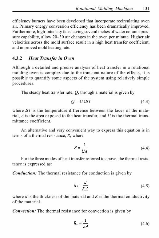
The steady heat transfer rate, Q, through a material is given by
Q = UA∆T (4.3)
where ∆T is the temperature difference between the faces of the mate-rial, A is the area exposed to the heat transfer, and U is the thermal trans-mittance coefficient.
An alternative and very convenient way to express this equation is interms of a thermal resistance, R, where
(4.4)
For the three modes of heat transfer referred to above, the thermal resis-tance is expressed as:
Conduction: The thermal resistance for conduction is given by
(4.5)
where d is the thickness of the material and K is the thermal conductivityof the material.
Convection: The thermal resistance for convection is given by
(4.6)
132 Rotational Molding Technology
where h is the heat transfer coefficient. As described earlier, its valuedepends on the conditions at the surface layer between the solid and thefluid. It is influenced by the surface geometry, the nature of the fluid motion,and a variety of other thermodynamic parameters.
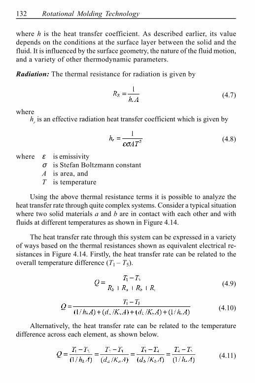
Radiation: The thermal resistance for radiation is given by
(4.7)
wherehr is an effective radiation heat transfer coefficient which is given by
(4.8)
where ε is emissivityσ is Stefan Boltzmann constantA is area, andT is temperature
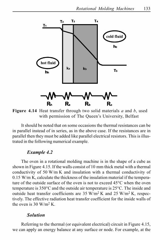
Using the above thermal resistance terms it is possible to analyze theheat transfer rate through quite complex systems. Consider a typical situationwhere two solid materials a and b are in contact with each other and withfluids at different temperatures as shown in Figure 4.14.
The heat transfer rate through this system can be expressed in a varietyof ways based on the thermal resistances shown as equivalent electrical re-sistances in Figure 4.14. Firstly, the heat transfer rate can be related to theoverall temperature difference (T1 � T5).
(4.9)
(4.10)
Alternatively, the heat transfer rate can be related to the temperaturedifference across each element, as shown below.
(4.11)
Rotational Molding Machines 133
Figure 4.14 Heat transfer through two solid materials a and b, usedwith permission of The Queen�s University, Belfast
It should be noted that on some occasions the thermal resistances can bein parallel instead of in series, as in the above case. If the resistances are inparallel then they must be added like parallel electrical resistors. This is illus-trated in the following numerical example.
Example 4.2
The oven in a rotational molding machine is in the shape of a cube asshown in Figure 4.15. If the walls consist of 10 mm thick metal with a thermalconductivity of 50 W/m K and insulation with a thermal conductivity of0.15 W/m K, calculate the thickness of the insulation material if the tempera-ture of the outside surface of the oven is not to exceed 45°C when the oventemperature is 350°C and the outside air temperature is 25°C. The inside andoutside heat transfer coefficients are 35 W/m2 K and 25 W/m2 K, respec-tively. The effective radiation heat transfer coefficient for the inside walls ofthe oven is 30 W/m2 K.
Solution
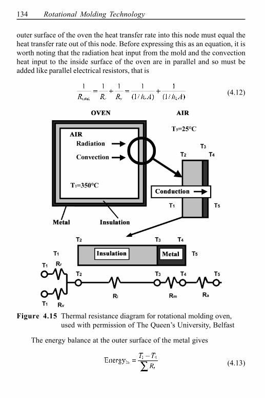
Referring to the thermal (or equivalent electrical) circuit in Figure 4.15,we can apply an energy balance at any surface or node. For example, at the
134 Rotational Molding Technology
outer surface of the oven the heat transfer rate into this node must equal theheat transfer rate out of this node. Before expressing this as an equation, it isworth noting that the radiation heat input from the mold and the convectionheat input to the inside surface of the oven are in parallel and so must beadded like parallel electrical resistors, that is
(4.12)
Figure 4.15 Thermal resistance diagram for rotational molding oven,used with permission of The Queen�s University, Belfast
The energy balance at the outer surface of the metal gives
(4.13)
Rotational Molding Machines 135
where
(4.14)
And the energy out is given by
(4.15)
Equating the Energy In to the Energy Out and rearranging to get thethickness of the insulation yields:
(4.16)
Using the data given in the question
Tair = 25 Ta = 350 hc = 25 hh = 35 hr = 30
db = 0.01 T0 = 45 Ka = 0.15 Kb = 50
the required thickness of the insulation is 89 mm. It should be noted thatdue to the high thermal conductivity of the metal and its relative thinness,it offers very little resistance to heat transfer by conduction. The thick-ness of the insulation required is directly proportional to its thermal con-ductivity. Also, in this calculation any radiated heat from the wall beinganalyzed has been ignored.
4.3.3 Oven Air Flow Amplification
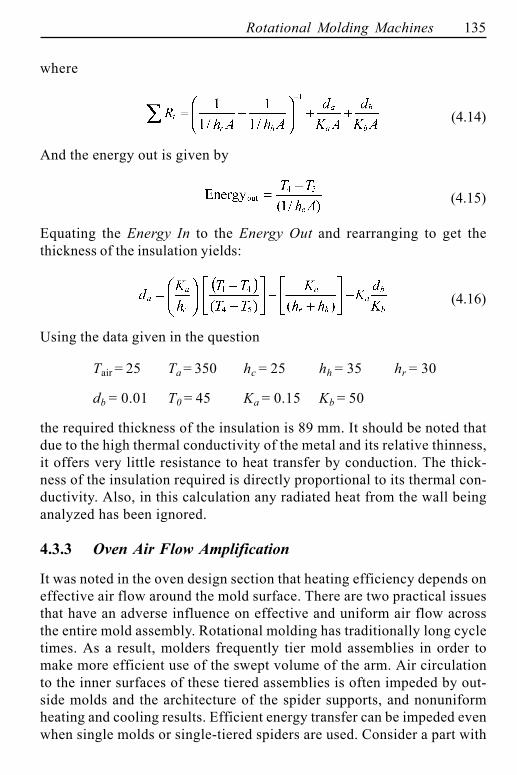
It was noted in the oven design section that heating efficiency depends oneffective air flow around the mold surface. There are two practical issuesthat have an adverse influence on effective and uniform air flow acrossthe entire mold assembly. Rotational molding has traditionally long cycletimes. As a result, molders frequently tier mold assemblies in order tomake more efficient use of the swept volume of the arm. Air circulationto the inner surfaces of these tiered assemblies is often impeded by out-side molds and the architecture of the spider supports, and nonuniformheating and cooling results. Efficient energy transfer can be impeded evenwhen single molds or single-tiered spiders are used. Consider a part with
136 Rotational Molding Technology
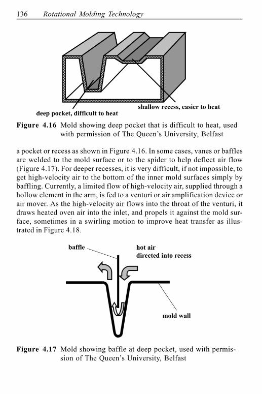
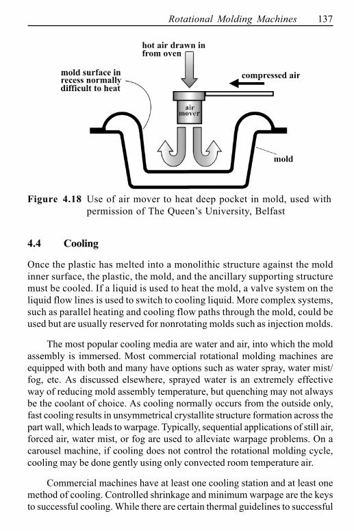
a pocket or recess as shown in Figure 4.16. In some cases, vanes or bafflesare welded to the mold surface or to the spider to help deflect air flow(Figure 4.17). For deeper recesses, it is very difficult, if not impossible, toget high-velocity air to the bottom of the inner mold surfaces simply bybaffling. Currently, a limited flow of high-velocity air, supplied through ahollow element in the arm, is fed to a venturi or air amplification device orair mover. As the high-velocity air flows into the throat of the venturi, itdraws heated oven air into the inlet, and propels it against the mold sur-face, sometimes in a swirling motion to improve heat transfer as illus-trated in Figure 4.18.
Figure 4.17 Mold showing baffle at deep pocket, used with permis-sion of The Queen�s University, Belfast
Figure 4.16 Mold showing deep pocket that is difficult to heat, usedwith permission of The Queen�s University, Belfast
Rotational Molding Machines 137
Figure 4.18 Use of air mover to heat deep pocket in mold, used withpermission of The Queen�s University, Belfast
4.4 Cooling
Once the plastic has melted into a monolithic structure against the moldinner surface, the plastic, the mold, and the ancillary supporting structuremust be cooled. If a liquid is used to heat the mold, a valve system on theliquid flow lines is used to switch to cooling liquid. More complex systems,such as parallel heating and cooling flow paths through the mold, could beused but are usually reserved for nonrotating molds such as injection molds.
The most popular cooling media are water and air, into which the moldassembly is immersed. Most commercial rotational molding machines areequipped with both and many have options such as water spray, water mist/fog, etc. As discussed elsewhere, sprayed water is an extremely effectiveway of reducing mold assembly temperature, but quenching may not alwaysbe the coolant of choice. As cooling normally occurs from the outside only,fast cooling results in unsymmetrical crystallite structure formation across thepart wall, which leads to warpage. Typically, sequential applications of still air,forced air, water mist, or fog are used to alleviate warpage problems. On acarousel machine, if cooling does not control the rotational molding cycle,cooling may be done gently using only convected room temperature air.
Commercial machines have at least one cooling station and at least onemethod of cooling. Controlled shrinkage and minimum warpage are the keysto successful cooling. While there are certain thermal guidelines to successful
138 Rotational Molding Technology
cooling, such as polymer temperature profile inversion, discussed elsewhere,fine-tuning of the cooling cycle is usually by trial-and-error. The typical watercooling station is a galvanized or stainless steel sheet-metal box, with a corro-sion-resistant floor having adequate drain holes. There are many types ofwater jetting or spraying nozzles. If drenching is needed, high volume flow�shower heads� are mounted above the mold assembly. Fog or fine mist nozzlesare usually mounted at the corners of the cooling chamber, to provide a sus-pended �cloud� of moisture droplets with low settling velocity. This allows themold assembly to pass through the cloud and leads to more uniform cooling.Fog and mist nozzles are recommended when the mold is relatively thin orwhen the polymer cannot be thermally shocked by flooding or drenching.Chemically treated and conditioned water is always recommended, to mini-mize scale build-up and rusting of steel parts on the mold assembly. Nearly allcommercial operations using water recycle the water for economic reasons.
Air-moving fans are selected for high-velocity, high-volume flow. Blow-ers are sometimes used, but compressor-blowers are usually not used. Posi-tive ventilation is needed in the cooling station if the polymer outgases noxiousfumes such as HCl from PVC. From a mechanical viewpoint, there is littlepoint to rotating the mold when the polymer is below the melting temperatureor glass transition temperature. With crosslinked materials the rotations couldstop as soon as the mold leaves the oven. However, to provide uniform cool-ing, the mold assembly is usually rotated in the cooling environment through-out the cooling cycle.
4.5 Process Monitors
Although oven temperature is considered to be constant throughout theheating process, this is not the case. Oven air temperature drops when theoven doors are opened at the beginning and end of the heating cycle. Theoven temperature can overshoot the target value by 30°C (50°F) or sobefore settling onto the set-point temperature. Also, it has been shownrepeatedly8, 9 that on the vast majority of machines, the oven tempera-tures are not uniform throughout the oven, even at the end of the heatingcycle. And most certainly, the mold temperature never reaches the settemperature of the oven. The mold temperature is changing throughout itstime in the oven, and since this is what influences the plastic temperature,it is apparent that complex transient heat transfer phenomena are takingplace throughout the cycle. Some of the mold temperature changes are
Rotational Molding Machines 139
attributable to oven design and some to the inherent obstruction in air flowdue to mold/spider structure on the arm itself. All of this calls into ques-tion the control strategy for rotational molding machines, which is nor-mally based on the temperature of a thermocouple located in a remotecorner of the oven.
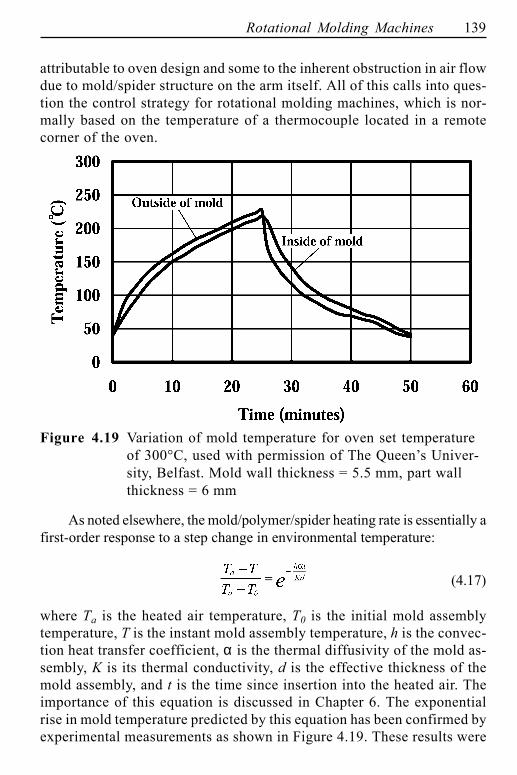
Figure 4.19 Variation of mold temperature for oven set temperatureof 300°C, used with permission of The Queen�s Univer-sity, Belfast. Mold wall thickness = 5.5 mm, part wallthickness = 6 mm
As noted elsewhere, the mold/polymer/spider heating rate is essentially afirst-order response to a step change in environmental temperature:
(4.17)
where Ta is the heated air temperature, T0 is the initial mold assemblytemperature, T is the instant mold assembly temperature, h is the convec-tion heat transfer coefficient, α is the thermal diffusivity of the mold as-sembly, K is its thermal conductivity, d is the effective thickness of themold assembly, and t is the time since insertion into the heated air. Theimportance of this equation is discussed in Chapter 6. The exponentialrise in mold temperature predicted by this equation has been confirmed byexperimental measurements as shown in Figure 4.19. These results were
140 Rotational Molding Technology
obtained by attaching thermocouples to the mold, on its surface, and throughthe mold thickness, and transmitting the data to a computer as the moldrotates. Infrared detectors have been used to measure mold surface tem-peratures10�12 and have shown similar temperature profiles.
Extensive trials have shown that the most reliable means to control theprocess is based on the temperature of the air inside the mold.13 A variety ofcommercial systems are available to do this, but at this stage, none have beenused to directly control the rotational molding cycle. This is likely to happen inthe near future as cycle times are reduced and more robust insulation be-comes available to protect the sensitive electronics when the equipment isused on hot air machines. The development of high temperature slip rings totake electrical signals from the mold and the use of ovenless machines alsomake this type of process control relatively straightforward. The basis of thistype of process control is discussed next.
4.5.1 Internal Air Temperature Measurement in RotationalMolding
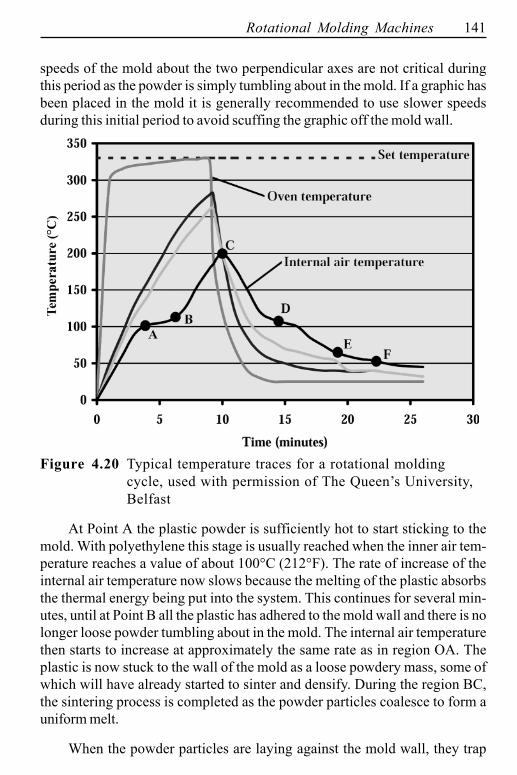
In the vast majority of cases, the rotational molding process involves heat-ing a powdered plastic in a rotating metal mold. Normally the heating isdone in an oven and this is the situation that will be considered now. Withproper measuring equipment, time-dependent oven temperature, mold tem-perature, and the temperature of the air inside the mold can be obtained,as shown in Figure 4.20. These data have characteristic shapes that areunique to rotational molding, particularly the internal air temperature trace.13
Consider the temperature traces in Figure 4.20 in detail.14 The set tem-perature for the oven is 330°C (626°F). When the cycle starts, oven environ-mental air temperature immediately starts to increase toward a predeterminedset temperature. However, it is several minutes before the temperatures ofthe mold, the plastic, and the air inside the mold begin to increase. The lowerline in Figure 4.20 is the temperature of the air inside the mold. The two linesabove it are the temperatures of the outside surface and inside surface of themold. In the oven the outer surface has the higher temperature and in thecooling chamber the outer surface is the cooler of the two.
The temperature trace for the air inside the mold provides the most inter-esting information. Once the internal air temperature begins to increase, itincreases steadily. Up to Point A there is no powder sticking to the moldbecause the plastic has not reached its �tacky� temperature. The rotational
Rotational Molding Machines 141
speeds of the mold about the two perpendicular axes are not critical duringthis period as the powder is simply tumbling about in the mold. If a graphic hasbeen placed in the mold it is generally recommended to use slower speedsduring this initial period to avoid scuffing the graphic off the mold wall.
Figure 4.20 Typical temperature traces for a rotational moldingcycle, used with permission of The Queen�s University,Belfast
At Point A the plastic powder is sufficiently hot to start sticking to themold. With polyethylene this stage is usually reached when the inner air tem-perature reaches a value of about 100°C (212°F). The rate of increase of theinternal air temperature now slows because the melting of the plastic absorbsthe thermal energy being put into the system. This continues for several min-utes, until at Point B all the plastic has adhered to the mold wall and there is nolonger loose powder tumbling about in the mold. The internal air temperaturethen starts to increase at approximately the same rate as in region OA. Theplastic is now stuck to the wall of the mold as a loose powdery mass, some ofwhich will have already started to sinter and densify. During the region BC,the sintering process is completed as the powder particles coalesce to form auniform melt.
When the powder particles are laying against the mold wall, they trap
142 Rotational Molding Technology
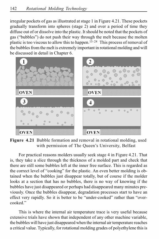
irregular pockets of gas as illustrated at stage 1 in Figure 4.21. These pocketsgradually transform into spheres (stage 2) and over a period of time theydiffuse out of or dissolve into the plastic. It should be noted that the pockets ofgas (�bubbles�) do not push their way through the melt because the moltenplastic is too viscous to allow this to happen.15�24 This process of removal ofthe bubbles from the melt is extremely important in rotational molding and willbe discussed in detail in Chapter 6.
Figure 4.21 Bubble formation and removal in rotational molding, usedwith permission of The Queen�s University, Belfast
For practical reasons molders usually seek stage 4 in Figure 4.21. Thatis, they take a slice through the thickness of a molded part and check thatthere are still some bubbles left at the inner free surface. This is regarded asthe correct level of �cooking� for the plastic. An even better molding is ob-tained when the bubbles just disappear totally, but of course if the molderlooks at a section that has no bubbles, there is no way of knowing if thebubbles have just disappeared or perhaps had disappeared many minutes pre-viously. Once the bubbles disappear, degradation processes start to have aneffect very rapidly. So it is better to be �under-cooked� rather than �over-cooked.�
This is where the internal air temperature trace is very useful becauseextensive trials have shown that independent of any other machine variable,the bubbles will have just disappeared when the internal air temperature reachesa critical value. Typically, for rotational molding grades of polyethylene this is
Rotational Molding Machines 143
about 200°C (392°F). Thus, by ensuring that this value of internal air tem-perature is always reached, the molder is able to produce a good moldingevery time. At this point the mold can be taken out of the oven and the coolingstage begins. It should be noted in Figure 4.20 that it is not uncommon for thetemperature of the internal air to continue rising after the mold comes out ofthe oven. This is particularly the case if the wall of the plastic part is quitethick. Therefore it is necessary to allow for this overshoot when determiningthe optimum time in the oven.
Once cooling begins, the internal air temperature starts to decrease. Therate of decrease will depend on the type of cooling, in addition to part wallthickness and mold thickness. Water cooling causes a rapid drop in tempera-ture whereas air cooling is gentler. During the initial period of cooling, theplastic adhered to the mold wall is still molten. Its crystalline structure ormorphological characteristics are being formed and the rate of cooling willhave a major effect on the morphology of the end product. Properties such asimpact strength and physical characteristics such as shrinkage and warpageare affected dramatically by the cooling rate.
At a certain point the slope of the internal air temperature trace changesmarkedly (Point D). This is associated with the solidification of the plastic. Asit solidifies and crystallizes, the plastic gives off heat which means that theinternal air is not able to decrease in temperature as quickly as before. Oncethe plastic has become solid across the wall section, the internal air tempera-ture starts to decrease again at a rate similar, but usually slower, than the rateoccurring before solidification began. As the plastic is now solid, the rate ofcooling has less effect on the morphology of the plastic. Therefore fast cool-ing, using water, is permissible. The only thing that one has to be careful aboutis the unsymmetrical cooling across the wall thickness, if the mold is cooledfrom the outside only. This will tend to cause warpage. This phenomenon willbe discussed in detail later.
The final important stage in the cycle is Point E. It may be seen in Fig-ure 4.20 that this is characterized by a slight change in slope of the internal airtemperature trace. This indicates that the plastic is separating from the moldwall and an insulation layer of air is forming between the plastic and the mold.This means that the external cooling becomes less efficient and so the internalair temperature cannot decrease as quickly as before. It may be seen in Fig-ure 4.20 that the temperatures of the inner and outer surfaces of the moldbecome equal after this point. Eventually Point F, the demolding temperature,is reached.
144 Rotational Molding Technology
4.5.2 Infrared Temperature Sensors
Infrared sensors provide a convenient means of remote measurement oftemperature. In the context of rotational molding, where the motion of themold makes hard wire measurements difficult, infrared technology hasthe potential to be very useful. However, the rotating molds and associ-ated framework add complexity to the interpretation of the data receivedfrom the infrared sensor. The detector/camera is permanently mountedon the wall of the oven. Since the molds rotate through the infrared field,a video camera is necessary in order to ensure that the temperature beingmeasured is that of the mold, rather than that of the nonmold hardware,oven walls, or the supporting arm. Although reflection from the mold sur-face can mislead the infrared detector, the effect is usually quite tran-sient. The approach taken has been to treat the data collected as a map ofthe surface of the mold, and by sampling data at high rates, smoothingtechniques can be used to get an average temperature profile for themold.10 This can then be used to activate key steps in the machine cycle,such as moving from the heating stage to the cooling stage. It is importantto note that infrared systems need regular calibration using some othertemperature measuring system.
4.6 Servicing
There needs to be a physical location in the rotational molding environ-ment where the empty molds are inspected, cleaned, dried if necessary,charged with powder, where inserts and vent tubes are installed, and wherethe molds are closed and sealed. There also needs to be a physical loca-tion where the molds are unsealed and opened and where the parts areremoved. Usually these servicing steps, usually called load/unload sta-tions, are at the same physical location. Manpower requirement is high atthis location, since many events are happening during loading and unload-ing. For many home-built machines, molds are opened and closed manu-ally, parts are removed manually, and molds are inspected and chargedmanually. Parts need to be physically removed from this station and pow-der and inserts need to be physically delivered to this station. A growingtrend in commercial machines is to have automation in the service areas,particularly in regard to dispensing material into the mold. In some casesthere may also be automated mold opening, although there are fewinstances of robots being used in this industry.
Rotational Molding Machines 145
4.7 Advanced Machine Design
For decades, rotational molding has been viewed by the plastics industryas a relatively simple mechanical process involving heating the mold/poly-mer system while rotating the assembly about the two perpendicular axes.The major limitation to this powder-based process has always been thelong cycle time at an elevated temperature. While in theory most thermo-plastics and thermosets should lend themselves to rotational molding, manypolymers are simply too thermally sensitive for the current processingconditions. And many resin suppliers, not viewing rotational molding as aneconomically important process, have chosen not to alter their polymersto meet the unique demands of rotational molding. As a result, polyethyl-ene, in all its variations and through its normally thermally stable nature,has become the polymer of choice. As one considers ways to improvemachine design and, in particular, to reduce manufacturing costs, it is im-portant to realize that materials, molds, and molding machinery all have apart to play in such developments. Although the heat transfer processesare inherently slow in hot air oven machines, as discussed above, a majorcontributory factor to long cycle times is the thickness of the molded partand the fact that it is heated/cooled from one side only.
The fact that most rotationally molded parts are made from polyethylenemeans that shape must be used very effectively to compensate for the lowelastic modulus of this plastic. As will be discussed later, where possible,corrugated sections, kiss-off points, and other geometrical features are usedto impart stiffness to the end product. And of course thickness of the part is amajor factor in this. The transverse or flexural stiffness of a material is pro-portional to the cube of the thickness. Doubling the thickness gives a factor of8 improvement in stiffness. Not surprisingly therefore, most rotationally moldedparts are very much thicker than equivalent injection molded products.
There is a vicious circle therefore in that the molder uses polyethyleneand so the wall thicknesses must be large to achieve any reasonable proper-ties in the molding. This results in long cycle times and this in turn means thatthe process is restricted to polyethylene. If the rotational molding process hadaccess to higher modulus materials, the walls could be thinner, which meansthat the cycle times could be shorter and so thermal sensitivity would becomeless of an issue. Of course in addition to access to higher modulus materials,there must be more efficient heating and cooling to minimize the exposure ofthe plastic to the elevated temperatures.
146 Rotational Molding Technology
It is well known that thermally sensitive polymers, such as cellulosics,acrylics, and even styrenics, have been rotationally molded, primarily by alter-ing the atmosphere inside the mold. One well-practiced method is the intro-duction of dry ice pellets along with the powder charge to the mold cavity. Inthe past, only a few commercial machines had hollow arms that allowed inertgases such as carbon dioxide and/or nitrogen to be introduced directly into themold through the vent hole system. This hollow-arm concept has been devel-oped further in recent years. Now, most commercial machines have multipleflow channels through the arms.25 This allows for flow of inert gas to themold assembly, as well as flow of pressurized air for such activities as airflow amplification and drop box activation, as discussed later. The ability todraw a vacuum or negative pressure and to provide positive pressure hasbecome increasingly important as more is understood about the sinter-densifi-cation and cooling characteristics of rotationally molded polymers. The im-portance of this is discussed elsewhere.
Over the past decade a lot of technical information has been accumu-lated on the rotational molding process. Over the next decade it will be essen-tial that the industry applies this knowledge to make major improvements tothe performance of the molding equipment. Cycle times must be reduced to afraction of what they are today so that rotational molding can remain competi-tive against industrial blow molding and emerging technologies such as twinsheet thermoforming and gas assisted injection molding. The use of directmold heating/cooling needs to be perfected, the use of internal heating andcooling must be incorporated into commercial machines and the benefits ofmold pressurization need to be realized.18, 19, 21, 26�28 This will require a con-certed effort from material suppliers, mold manufacturers, and machinerybuilders to combine the best practice from each sector and advance the in-dustry for everyone.
Rotational Molding Machines 147
References
1. G.L. Beall, Rotational Molding � Design, Materials, Tooling andProcessing, Hanser/Gardner Publications, Munich/Cincinati, 1998.
2. R.J. Crawford, Ed., Rotational Moulding of Plastics, 2nd ed., ResearchStudies Press, London, 1996, p. 260.
3. P.F. Bruins, Ed., Basic Principles of Rotational Molding, Gordon andBreach, New York, 1971.
4. B. Carter, �Lest We Forget � Trials and Tribulations of the Early Rota-tional Molders,� paper presented at ARM Fall Meeting, Dallas, 1998.
5. A. Wytkin, �A New Rotational Moulding System � Composite MouldTechnology,� Rotation, 6:3 (1997), pp. 30�32.
6. A. Wytkin, �Composite Mold Upgrades Rotomolding Process Control,�Mod. Plastics, 75:1 (Jan. 1998), pp. 2�3.
7. M.J. Wright and R.J. Crawford, �A Comparison Between Forced AirConvection Heating and Direct Electrical Heating of Moulds in Rota-tional Moulding,� SPE ANTEC Tech. Papers, 45:1 (1999), pp. 1452�1456.
8. M.J. Wright, A.G. Spence, and R.J. Crawford. �An Analysis of HeatingEfficiency in Rotational Moulding,� SPE ANTEC Tech. Papers, 53:3(1997), pp. 3184�3188.
9. S. Bawiskar and J.L. White, �Simulation of Heat Transfer and Melting inRotational Molding,� Int. Polym. Proc., 10:1 (1995), pp. 62�67.
10. P.J. Nugent, �Next Steps in Machine Control for Rotational Molding,�Rotation, 7:3 (1998), pp. 46�53.
11. P.J. Nugent and R.J. Crawford, �Process Control for Rotational Mould-ing,� in R.J. Crawford, Ed., Rotational Moulding of Plastics, 2nd ed.,John Wiley & Sons, Inc., New York, 1996, pp. 196�215.
12. P. Nugent, �Use of Non-Contact Temperature Sensing in Extending Pro-cess Control for Rotational Molding,� SPE ANTEC Tech. Papers, 53:3(1997), pp. 3200�3204.
13. Crawford, R.J. and P.J. Nugent, �Rotational Moulding Apparatus andProcess,� U.S. Patent No. 5,322,654 (June 21, 1994), Assigned to TheQueen�s University of Belfast, Belfast U.K.
14. R.J. Crawford and P.J. Nugent, �A New Process Control System forRotational Moulding,� Plast. Rubber Comp.: Proc. Appln., 17:1 (1992),pp. 23�31.
15. J.A. Scott, A Study of the Effects of Process Variables on the Proper-ties of Rotationally Moulded Plastic Articles, Ph.D. Thesis in Me-chanical and Manufacturing Engineering, The Queen�s University, Belfast,1986.
148 Rotational Molding Technology
16. A.G. Spence, Analysis of Bubble Formation and Removal in Rota-tionally Moulded Products, Ph.D. Thesis in Mechanical and Manufac-turing Engineering, The Queen�s University, Belfast, p. 340.
17. G. Gogos, �Bubble Removal in Rotational Molding,� paper presented atSociety of Plastics Engineers (SPE) Topical Conference on RotationalMolding, Cleveland, OH, 1999.
18. A.G. Spence and R.J. Crawford, �Pin-holes and Bubbles in RotationallyMoulded Products,� in R.J. Crawford, Ed., Rotational Moulding, Re-search Studies Press, London, 1996, pp. 217�242.
19. A.G. Spence and R.J. Crawford, �Removal of Pin-holes and Bubblesfrom Rotationally Moulded Products,� Proc. Instn. Mech. Engrs., PartB. J. Eng. Man., 210 (1996), pp. 521�533.
20. A.G. Spence and R.J. Crawford, �The Effect of Processing Variables onthe Formation and Removal of Bubbles in Rotationally Molded Products,�Polym. Eng. Sci., 36:7 (1996), pp. 993�1009.
21. A.G. Spence and R.J. Crawford, �Simulated Bubble Removal UnderPressurised Rotational Moulding Conditions,� Rotation, 4:3 (1995), pp.17�23.
22. A.G. Spence and R.J. Crawford, �An Investigation of the Occurance ofGas Bubbles in Rotationally Moulded Products,� Rotation, 4:2 (1995), pp.9�14.
23. A.G. Spence and R.J. Crawford, �Mould Pressurisation Removes Bubblesand Improves Quality of Rotationally Moulded Products,� Rotation, 4:2(1995), pp. 16�23.
24. R.J. Crawford and J.A. Scott, �The Formation and Removal of GasBubbles in a Rotational Moulding Grade of PE,� Plast. Rubber Proc.Appln., 7:2 (1987), pp. 85�99.
25. J. Crouch, �Multiple Passage Gas Supply System for Rotomoulding Ma-chines,� paper presented at BPF Rotomoulding Conference, Leicester,U.K., 1995.
26. C.-H. Chen, J.L. White, and Y. Ohta, �Mold Pressurization as a Methodto Reduce Warpage in Rotational Molding of Polyethylene,� Polym. Eng.Sci., 30:23 (1990), pp. 1523�1528.
27. C.-H. Chen and J.L. White, �A Guide to Warpage and Shrinkage ofRotationally Molded Parts,� paper presented at ARM Fall Meeting,Toronto, 1989.
28. K. Iwakura, Y. Ohta, C.-H. Chen, and J.L. White, �A Basic Study ofWarpage and Heat Transfer in Rotational Molding,� SPE ANTEC Tech.Papers, 35 (1989), pp. 558�562.