Embed Size (px)
Citation preview
Version 1.0
Rover 20A | 30A | 40AMaximum Power Point Tracking Solar Charge Controller
Rover Series
01
General Safety Information
Charge Controller Safety
Important Safety Instructions Please save these instructions.
This manual contains important safety, installation, and operating instructions for the charge controller. The following symbols are used throughout the manual to indicate potentially dangerous conditions or important safety information.
There are no serviceable parts for this controller. Do NOT disassemble or attempt to repair the controller.
Make sure all connections going into and from the controller are tight.
NEVER connect the solar panel array to the controller without a battery. Battery must be connected first.
Ensure input voltage does not exceed 100 VDC to prevent permanent damage. Use the Open Circuit Voltage (Voc) to make sure the voltage does not exceed this value when connecting panels together.
Read all of the instructions and cautions in the manual before beginning the installation.
Do NOT allow water to enter the controller.
NOTE
CAUTION
WARNING Indicates a potentially dangerous condition. Use extreme caution when performing this task
Indicates a critical procedure for safe and proper operation of the controller
Indicates a procedure or function that is important to the safe and proper operation of the controller
02
Battery Safety
Use only sealed lead-acid, flooded, gel or lithium batteries which must be deep cycle.
Explosive battery gases may be present while charging. Be certain there is enough ventilation to release the gases.
Be careful when working with large lead acid batteries. Wear eye protection and have fresh water available in case there is contact with the battery acid.
Over-charging and excessive gas precipitation may damage the battery plates and activate material shedding on them. Too high of an equalizing charge or too long of one may cause damage. Please carefully review the specific requirements of the battery used in the system.
Equalization is carried out only for non-sealed / vented/ flooded / wet cell lead acid batteries.
Do NOT equalize VRLA type AGM / Gel / Lithium cell batteries UNLESS permitted by battery manufacturer.
Default charging parameters in Li mode are programmed for 12.8V Lithium Iron Phosphate (LFP) Battery only. Before using Rover to charge other types of lithium battery, set the parameters according to the suggestions from battery manufacturer.
Carefully read battery manuals before operation.
Do NOT let the positive (+) and negative (-) terminals of the battery touch each other.
Connect battery terminals to the charge controller BEFORE connecting the solar panel(s) to the charge controller. NEVER connect solar panels to charge controller until the battery is connected.
Do NOT connect any inverters or battery charger into the load terminal of the charge controller.
Once equalization is active in the battery charging, it will not exit this stage unless there is adequate charging current from the solar panel. There should be NO load on the batteries when in equalization charging stage.
WARNING
Recycle battery when it is replaced.
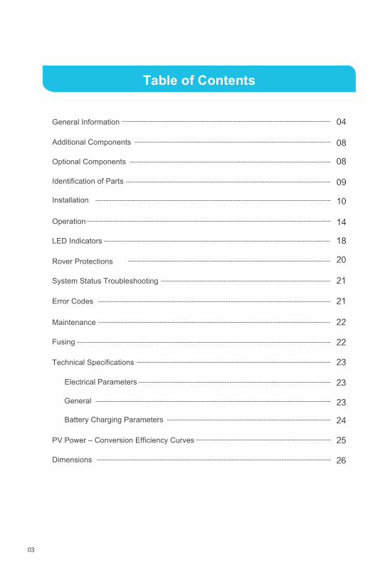
Table of Contents
03
General Information
Additional Components
Optional Components
Identification of Parts
Operation
LED Indicators
Rover Protections
System Status Troubleshooting
Maintenance
Fusing
Technical Specifications
Electrical Parameters
Battery Charging Parameters
PV Power – Conversion Efficiency Curves
Dimensions
04
08
08
09
14
10
18
20
21
21
22
22
23
23
23
24
25
26
Installation
Error Codes
General
04
General Information
Customizable charging voltages
The MPPT Charge Controller utilizes Maximum Power Point Tracking technology to extract maximum power from the solar module(s). The tracking algorithm is fully automatic and does not require user adjustment. MPPT technology will track the array’smaximum power point voltage (Vmp) as it varies with weather conditions, ensuring that the maximum power is harvested from the array throughout the course of the day.
The Rover Series charge controllers are suitable for various off-grid solar applications. It protects the battery from being over-charged by the solar modules and over-discharged by the loads. The controller features a smart tracking algorithm that maximizes the energy from the solar PV module(s) and charge the battery. At the same time, the low voltage disconnect function (LVD) will prevent the battery from over discharging.
The Rover's charging process has been optimized for long battery life and improved system performance. The comprehensive self-diagnostics and electronic protection functions can prevent damage from installation mistakes or system faults.
In many cases, the MPPT charge controller will “boost” up the current in the solar system. The current does not come out of thin air. Instead, the power generated in the solar panels is the same power that is transmitted into the battery bank. Power is the product of Voltage (V) x Amperage (A).
Automatically detect 12V or 24V DC system voltages
Deep cycle Sealed, Gel, Flooded and Lithium (12.8V LFP) battery option readyElectronic protection: Overcharging, over-discharging, overload, and short circuit
Innovative MPPT technology with high tracking efficiency up to 99% and peak conversion efficiency of 98%
Reverse protection: Any combination of solar module and battery, without causing damage to any component
Charges over-discharged lithium batteries
RS232 port to communicate with BT-1 Bluetooth module and PC
MPPT Technology
Current Boost
Key Features
05
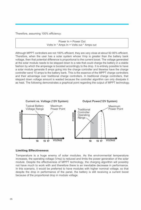
Therefore, assuming 100% efficiency:
Power In = Power OutVolts In * Amps In = Volts out * Amps out
Maximum Power Point Traditional
Controller Operating Range
Maximum Power Point
Although MPPT controllers are not 100% efficient, they are very close at about 92-95% efficient. Therefore, when the user has a solar system whose Vmp is greater than the battery bank voltage, then that potential difference is proportional to the current boost. The voltage generated at the solar module needs to be stepped down to a rate that could charge the battery in a stable fashion by which the amperage is boosted accordingly to the drop. It is entirely possible to have a solar module generate 8 amps going into the charge controller and likewise have the charge controller send 10 amps to the battery bank. This is the essence of the MPPT charge controllers and their advantage over traditional charge controllers. In traditional charge controllers, that stepped down voltage amount is wasted because the controller algorithm can only dissipate it as heat. The following demonstrates a graphical point regarding the output of MPPT technology.
Temperature is a huge enemy of solar modules. As the environmental temperature increases, the operating voltage (Vmp) is reduced and limits the power generation of the solar module. Despite the effectiveness of MPPT technology, the charging algorithm will possibly not have much to work with and therefore there is an inevitable decrease in performance. In this scenario, it would be preferred to have modules with higher nominal voltage, so that despite the drop in performance of the panel, the battery is still receiving a current boost because of the proportional drop in module voltage.
Limiting Effectiveness
Current vs. Voltage (12V System) Output Power(12V System)Typical Battery Voltage Range
06
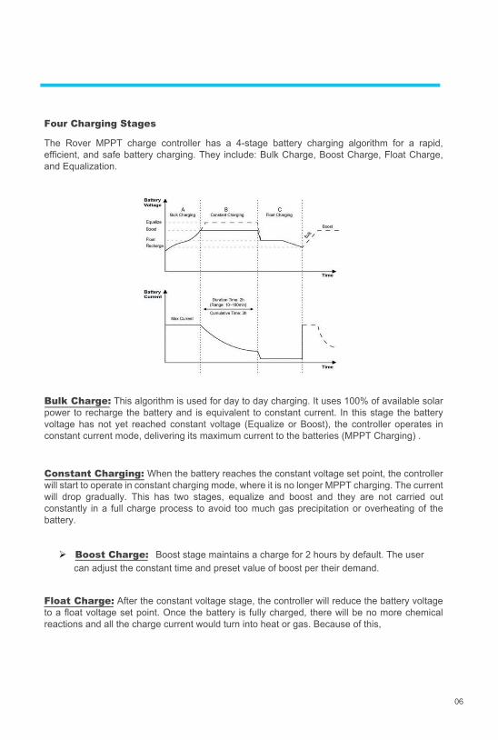
The Rover MPPT charge controller has a 4-stage battery charging algorithm for a rapid, efficient, and safe battery charging. They include: Bulk Charge, Boost Charge, Float Charge, and Equalization.
Bulk Charge: This algorithm is used for day to day charging. It uses 100% of available solar power to recharge the battery and is equivalent to constant current. In this stage the battery voltage has not yet reached constant voltage (Equalize or Boost), the controller operates in constant current mode, delivering its maximum current to the batteries (MPPT Charging) .
Float Charge: After the constant voltage stage, the controller will reduce the battery voltage to a float voltage set point. Once the battery is fully charged, there will be no more chemical reactions and all the charge current would turn into heat or gas. Because of this,
Constant Charging: When the battery reaches the constant voltage set point, the controller will start to operate in constant charging mode, where it is no longer MPPT charging. The current will drop gradually. This has two stages, equalize and boost and they are not carried out constantly in a full charge process to avoid too much gas precipitation or overheating of the battery.
Boost Charge: Boost stage maintains a charge for 2 hours by default. The user can adjust the constant time and preset value of boost per their demand.
Four Charging Stages
07
The charge controller will reduce the voltage charge to smaller quantity, while lightly charging the battery. The purpose for this is to offset the power consumption while maintaining a full battery storage capacity. In the event that a load drawn from the battery exceeds the charge current, the controller will no longer be able to maintain the battery to a Float set point and the controller will end the float charge stage and refer back to bulk charging.
The Rover MPPT charge controller has a reactivation feature to awaken a sleeping lithium battery. The protection circuit of lithium battery will typically turn the battery off and make it unusable if over-discharged. This can happen when storing a lithium battery pack in a discharged state for any length of time as self-discharge would gradually deplete the remaining charge. Without the wake-up feature to reactivate and recharge batteries, these batteries would become unserviceable and the packs would be discarded. The Rover will apply a small charge current to activate the protection circuit and if a correct cell voltage can be reached, it starts a normal charge.
Equalization: Is carried out every 28 days of the month. It is intentional overcharging of the battery for a controlled period of time. Certain types of batteries benefit from periodic equalizing charge, which can stir the electrolyte, balance battery voltage and complete chemical reaction. Equalizing charge increases the battery voltage, higher than the standard complement voltage, which gasifies the battery electrolyte.
When using the Rover to charge a 24V lithium battery bank, set the system voltage to 24V instead of auto recognition. If auto recognition is accidently selected the Rover will allow you to change it to 24V when the lithium battery activation feature is activated. In the activation interface press and hold the enter button to trigger the system voltage selector. To change the system voltage, press the Up or Down buttons then long press Enter to save the selected system voltage.
Lithium Battery Activation
Once equalization is active in the battery charging, it will not exit this stage unless there is adequate charging current from the solar panel. There should be NO load on the batteries when in equalization charging stage.
Over-charging and excessive gas precipitation may damage the battery plates and activate material shedding on them. Too high of equalizing charge or for too long may cause damage. Please carefully review the specific requirements of the battery used in the system.
Equalization may increase battery voltage to a level damaging to sensitive DC loads. Ensure that all load allowable input voltages are greater than the equalizing charging set point voltage.
CAUTION
WARNING
WARNING
WARNING
08
Additional Components
Optional Components
Additional components included in the package:
Optional components that require a separate purchase:
This sensor measures the temperature at the battery and uses this data for very accurate temperature compensation. Accurate temperature compensation is important in ensuring proper battery charging regardless of the temperature.
The BT-1 Bluetooth module is a great addition to any Renogy charge controllers with a RS232 port and is used to pair charge controllers with the Renogy BT App. After pairing is done you can monitor your system and change parameters directly from you cell phone or tablet. No more wondering how your system is performing, now you can see performance in real time without the need of checking on the controller’s LCD.
This PC communication cable is needed for remote monitoring using an optional PC software. Through the software, users could customize their charge parameters and other settings. Download the PC software through Renogy’s website under the “Downloads” section.
NOTE
NOTE
WARNING
Do Not use this sensor when charging lithium battery.
Do NOT use a PC Ethernet cable. This can and will cause permanent damage to a computer.
PC Communication requires the USB be connected at all times. Wireless capability not available.
Renogy BT-1 Bluetooth Module:
Remote Temperature Sensor:
USB to RS-232 Converter Cable:
○9 ○10 ○11 ○12○8
Key Parts
09
Identification of Parts
○3○4
○6
○5
○2○1
○7
1. PV LED Indicator 2. Battery LED Indicator 3. Load LED Indicator 4. System Error LED Indicator 5. LCD Screen 6. Operating Keys7. Mounting Holes 8. Remote Temperature Sensor Port (optional accessory) 9. PV Terminals 10. Battery Terminals 11. Load Terminals 12. RS-232 Port (optional accessory)
10
Installation
Connect battery terminal wires to the charge controller FIRST then connect the solar panel(s) to the charge controller. NEVER connect solar panel to charge controller before the battery.
Do NOT connect any inverters or battery chargers into the LOAD TERMINAL of the charge controller.
Recommended tools to have before installation:
Screwdriver
INVERTER
BATTERY CHARGER
HIGH AMP DRAWING DEVICE
Do not over tighten the screw terminals. This could potentially break the piece that holds the wire to the charge controller.
Refer to the technical specifications for max wire sizes on the controller and for the maximum amperage going through wires.
You are now ready to begin connecting your battery to your charge controller.
Multi-Meter
CAUTION
CAUTION
WARNING
WARNING
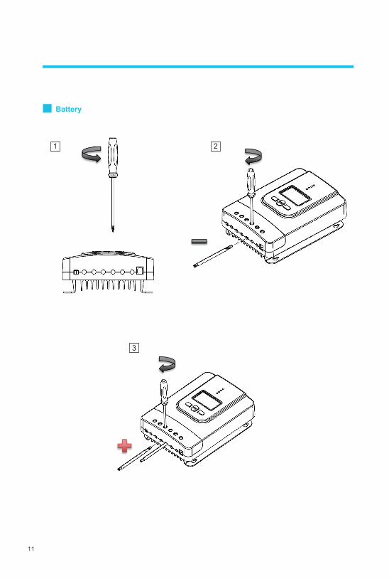
Battery
11
3
1 2
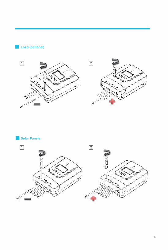
Load (optional)
Solar Panels
12
1 2
1 2
13
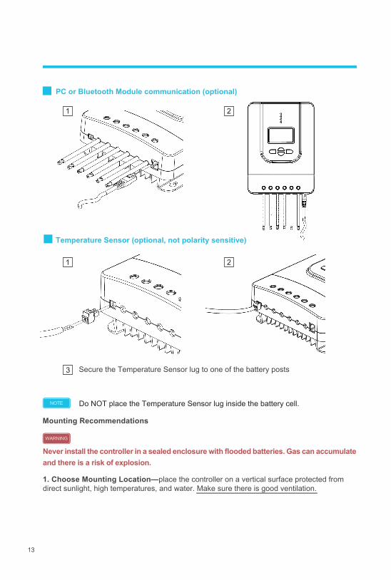
Temperature Sensor (optional, not polarity sensitive)
PC or Bluetooth Module communication (optional)
Mounting Recommendations
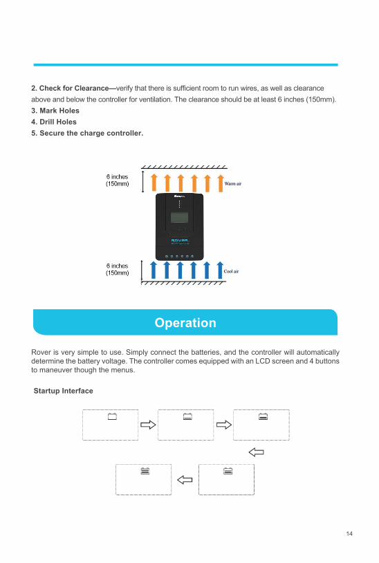
Never install the controller in a sealed enclosure with flooded batteries. Gas can accumulate and there is a risk of explosion.
1. Choose Mounting Location—place the controller on a vertical surface protected from direct sunlight, high temperatures, and water. Make sure there is good ventilation.
NOTE
WARNING
1 2
3
1 2
Secure the Temperature Sensor lug to one of the battery posts
Do NOT place the Temperature Sensor lug inside the battery cell.
14
Operation
2. Check for Clearance—verify that there is sufficient room to run wires, as well as clearance above and below the controller for ventilation. The clearance should be at least 6 inches (150mm). 3. Mark Holes 4. Drill Holes 5. Secure the charge controller.
Rover is very simple to use. Simply connect the batteries, and the controller will automatically determine the battery voltage. The controller comes equipped with an LCD screen and 4 buttons to maneuver though the menus.
Startup Interface
15
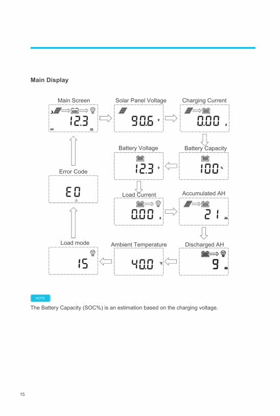
Main Display
Charging Current Main Screen Solar Panel Voltage
Error Code
Battery Voltage Battery Capacity
Load Current Accumulated AH
Load mode Discharged AH Ambient Temperature
The Battery Capacity (SOC%) is an estimation based on the charging voltage.
NOTE
16
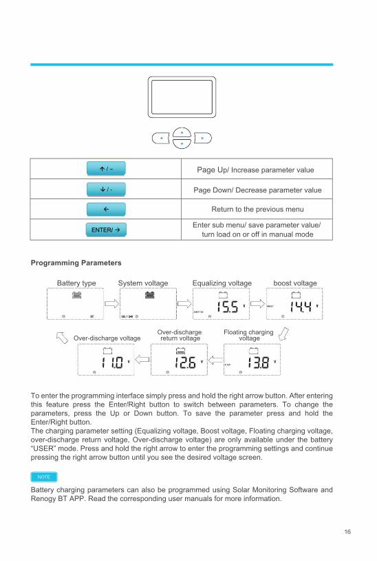
Page Down/ Decrease parameter value
Return to the previous menu
Enter sub menu/ save parameter value/
turn load on or off in manual mode
/ �
/ -
ENTER/
To enter the programming interface simply press and hold the right arrow button. After entering this feature press the Enter/Right button to switch between parameters. To change the parameters, press the Up or Down button. To save the parameter press and hold the Enter/Right button.The charging parameter setting (Equalizing voltage, Boost voltage, Floating charging voltage, over-discharge return voltage, Over-discharge voltage) are only available under the battery “USER” mode. Press and hold the right arrow to enter the programming settings and continue pressing the right arrow button until you see the desired voltage screen.
Battery charging parameters can also be programmed using Solar Monitoring Software and Renogy BT APP. Read the corresponding user manuals for more information.
Programming Parameters
Page Up/ Increase parameter value
NOTE
Over-discharge voltageOver-discharge return voltage
Battery type System voltage Equalizing voltage boost voltage
Floating charging voltage
17
Load Mode Options
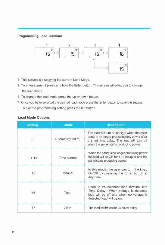
1 2 3 4
Programming Load Terminal
1. This screen is displaying the current Load Mode.
2. To enter screen 2 press and hold the Enter button. This screen will allow you to change
the load mode.
3. To change the load mode press the up or down button.
4. Once you have selected the desired load mode press the Enter button to save the setting.
5. To exit the programming setting press the left button.
Setting Mode Description
0 Automatic(On/Off)
Time control
15 Manual
16 Test
17 24Hr
The load will turn on at night when the solar panel is no longer producing any power after a short time delay. The load will turn off when the panel starts producing power.
When the panel is no longer producing power the load will be ON for 1-14 hours or until the panel starts producing power.
Used to troubleshoot load terminal (No Time Delay). When voltage is detected load will be off and when no voltage is detected load will be on.
In this mode, the user can turn the Load On/Off by pressing the Enter button at any time.
The load will be on for 24 hours a day.
1-14
18
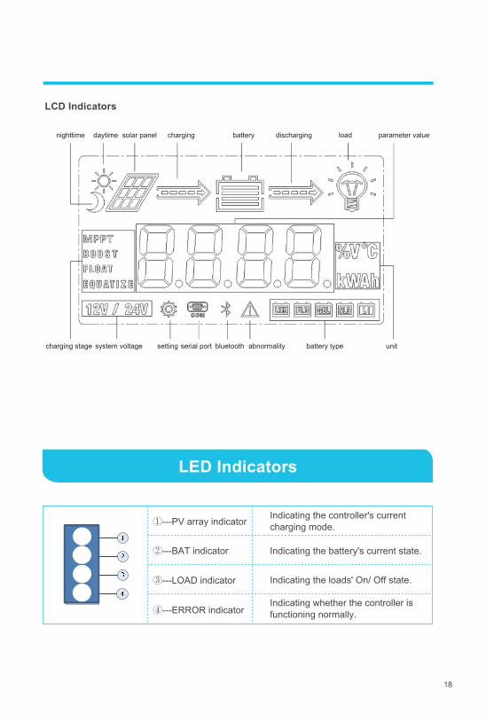
LED Indicators
LCD Indicators
①---PV array indicator Indicating the controller's current charging mode.
Indicating the battery's current state.
Indicating the loads' On/ Off state.
Indicating whether the controller is functioning normally.
②---BAT indicator
③---LOAD indicator
④---ERROR indicator
nighttime daytime solar panel charging
charging stage system voltage setting serial port bluetooth abnormality battery type unit
battery discharging load parameter value
19
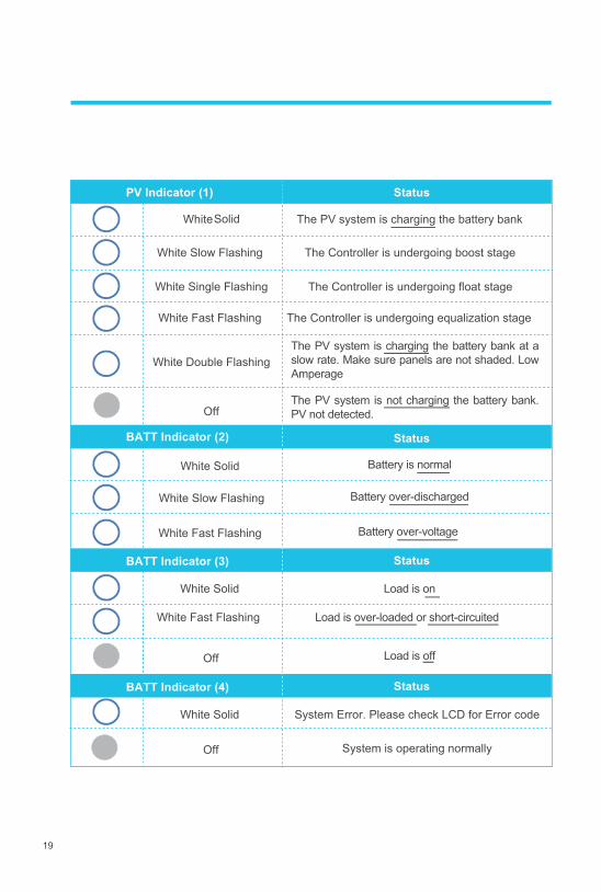
Status
WhiteSolid
Off
The Controller is undergoing boost stage
The Controller is undergoing float stage
The Controller is undergoing equalization stage
Status
White Solid
Off
System Error. Please check LCD for Error code
Off System is operating normally
Status
White Slow Flashing
White Single Flashing
White Fast Flashing
White Double Flashing
White Solid
White Fast Flashing
White Solid
White Fast Flashing
White Slow Flashing
Status
The PV system is charging the battery bank
The PV system is charging the battery bank at a slow rate. Make sure panels are not shaded. Low Amperage
The PV system is not charging the battery bank. PV not detected.
Battery over-voltage
Battery over-discharged
Battery is normal
Load is on
Load is over-loaded or short-circuited
Load is off
BATT Indicator (3)
BATT Indicator (2)
BATT Indicator (4)
PV Indicator (1)
20
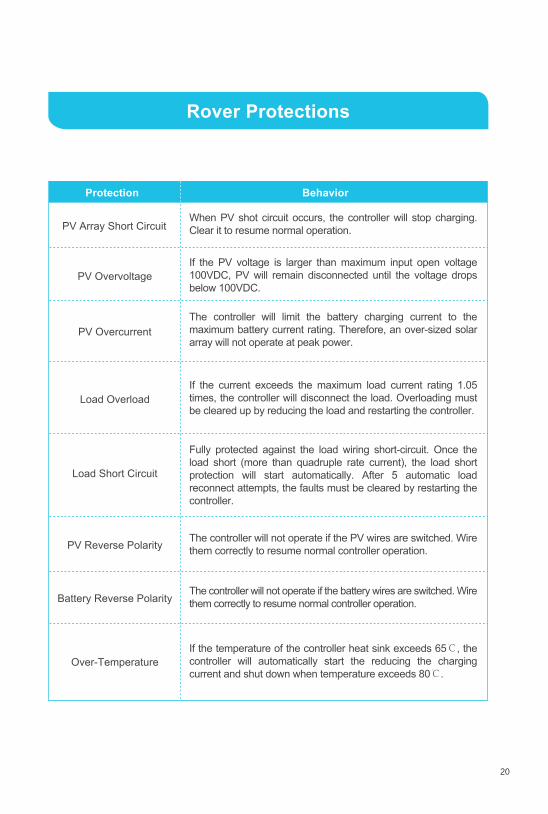
Rover Protections
Protection Behavior
When PV shot circuit occurs, the controller will stop charging. Clear it to resume normal operation.
If the PV voltage is larger than maximum input open voltage 100VDC, PV will remain disconnected until the voltage drops below 100VDC.
The controller will limit the battery charging current to the maximum battery current rating. Therefore, an over-sized solar array will not operate at peak power.
If the current exceeds the maximum load current rating 1.05 times, the controller will disconnect the load. Overloading must be cleared up by reducing the load and restarting the controller.
If the temperature of the controller heat sink exceeds 65℃, the controller will automatically start the reducing the charging current and shut down when temperature exceeds 80℃.
The controller will not operate if the PV wires are switched. Wire them correctly to resume normal controller operation.
The controller will not operate if the battery wires are switched. Wire them correctly to resume normal controller operation.
Fully protected against the load wiring short-circuit. Once the load short (more than quadruple rate current), the load short protection will start automatically. After 5 automatic load reconnect attempts, the faults must be cleared by restarting the controller.
Over-Temperature
Battery Reverse Polarity
PV Reverse Polarity
Load Short Circuit
Load Overload
PV Overcurrent
PV Overvoltage
PV Array Short Circuit
21
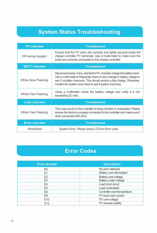
System Status Troubleshooting
PV indicator Troubleshoot
BATT Indicator Troubleshoot
Load Indicator Troubleshoot
Error Indicator Troubleshoot
Off during daylight
Using a multimeter check the battery voltage and verify it is not exceeding 32 volts.
Disconnect loads, if any, and let the PV modules charge the battery bank. Use a multi-meter to frequently check on any change in battery voltage to see if condition improves. This should ensure a fast charge. Otherwise, monitor the system and check to see if system improves.
The Load circuit on the controller is being shorted or overloaded. Please ensure the device is properly connected to the controller and make sure it does not exceed 20A (DC).
White Slow Flashing
White Fast Flashing
White Fast Flashing
WhiteSolid System Error. Please check LCD for Error code
Ensure that the PV wires are correctly and tightly secured inside the charge controller PV terminals. Use a multi-meter to make sure the poles are correctly connected to the charge controller.
Error Codes
E0E1E2E3E4 Load short circuitE5 Load overloadedE6E8E10
Error Number Description
PV over-voltagePV reverse polarity
PV input over-currentController over-temperature
Battery over-voltageBattery over-dischargedNo error detected
Battery under-voltage
E13
22
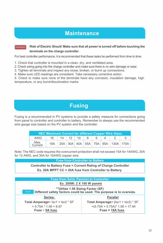
Maintenance
Fusing
AWG 16 14 12 10 8 6 4 2 0Max.
Current 55A40A30A25A18A 75A 95A 130A 170A
**Utilize 1.56 Sizing Factor (SF) Different safety factors could be used. The purpose is to oversize.
Series:Total Amperage= Isc1 = Isc2 * SF
ParallelTotal Amperage= (Isc1 + Isc2) * SF
1. Check that controller is mounted in a clean, dry, and ventilated area. 2. Check wiring going into the charge controller and make sure there is no wire damage or wear. 3. Tighten all terminals and inspect any loose, broken, or burnt up connections. 4. Make sure LED readings are consistent. Take necessary corrective action. 5. Check to make sure none of the terminals have any corrosion, insulation damage, high temperature, or any burnt/discoloration marks.
For best controller performance, it is recommended that these tasks be performed from time to time.
Risk of Electric Shock! Make sure that all power is turned off before touching the terminals on the charge controller.
Fusing is a recommended in PV systems to provide a safety measure for connections going from panel to controller and controller to battery. Remember to always use the recommended wire gauge size based on the PV system and the controller.
Note: The NEC code requires the overcurrent protection shall not exceed 15A for 14AWG, 20A for 12 AWG, and 30A for 10AWG copper wire.
NEC Maximum Current for different Copper Wire Sizes
Fuse from Controller to Battery
Fuse from Solar Panel(s) to ControllerEx. 200W; 2 X 100 W panels
Ex. 20A MPPT CC = 20A fuse from Controller to Battery Controller to Battery Fuse = Current Rating of Charge Controller
= 5.75A * 1.56 = 8.97 =(5.75A + 5.75A)* 1.56 = 17.94 Fuse = 18A fuse Fuse = 9A fuse
NOTE
WARNING
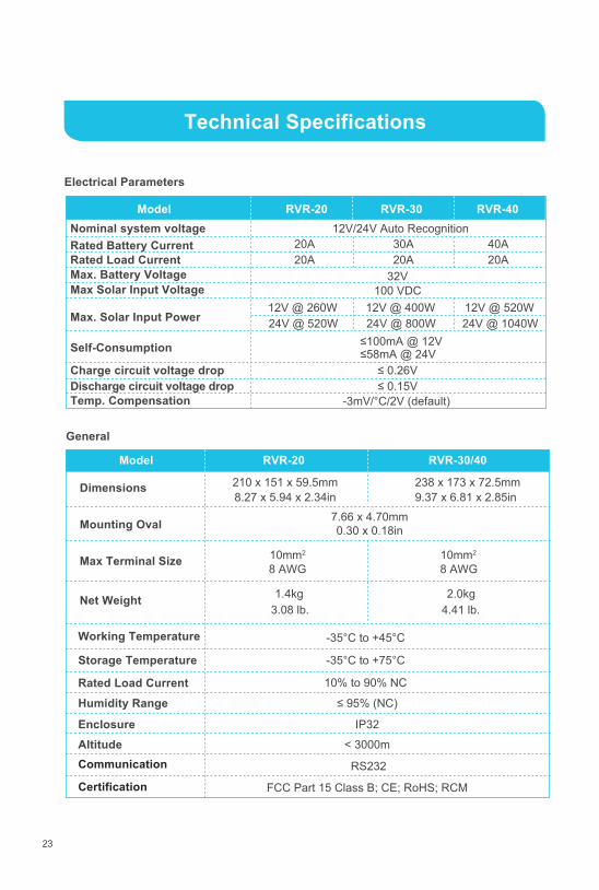
23
Technical Specifications
Electrical Parameters
Model Nominal system voltage
20A
40A
Rated Load Current
20A30A20A
20A
Max. Battery Voltage 32V Max Solar Input Voltage 100 VDC
Charge circuit voltage drop ≤ 0.26V Discharge circuit voltage drop ≤ 0.15V Temp. Compensation
RVR-20 RVR-30 RVR-40
12V @ 520W24V @ 1040W Max. Solar Input Power
Rated Battery Current
Self-Consumption
12V/24V Auto Recognition
12V @ 260W 24V @ 520W
12V @ 400W 24V @ 800W
≤100mA @ 12V ≤58mA @ 24V
-3mV/°C/2V (default)
General
Model
Dimensions
7.66 x 4.70mm
0.30 x 0.18in
Net Weight
RVR-20 RVR-30/40
Working Temperature
Storage Temperature
Rated Load Current≤ 95% (NC)
Enclosure IP32
Altitude < 3000m
-35°C to +45°C
-35°C to +75°C
10% to 90% NC
Humidity Range
238 x 173 x 72.5mm 9.37 x 6.81 x 2.85in
210 x 151 x 59.5mm8.27 x 5.94 x 2.34in
Mounting Oval
Max Terminal Size 8 AWG8 AWG
10mm2 10mm2
1.4kg3.08 lb.
2.0kg4.41 lb.
Communication
CertificationRS232
FCC Part 15 Class B; CE; RoHS; RCM
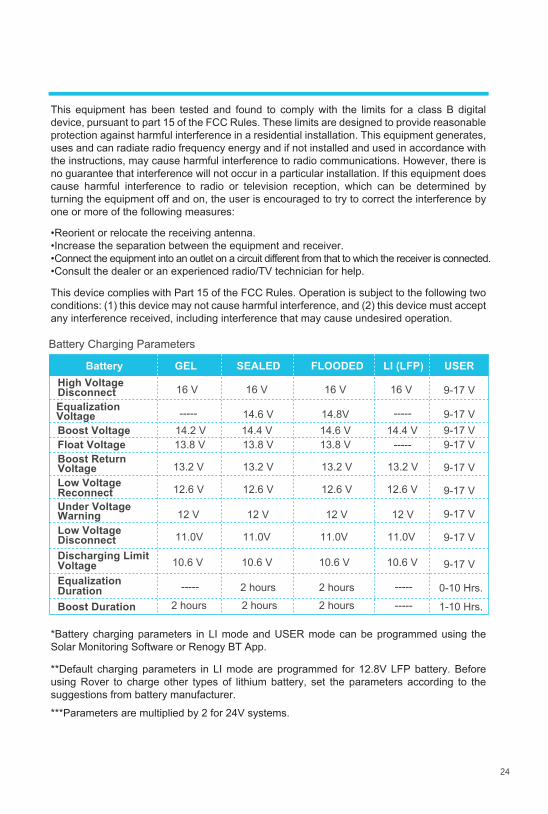
24
Battery GEL SEALED FLOODED LI (LFP) USERHigh Voltage Disconnect 16 V 16 V 16 V 16 VEqualization Voltage ----- -----14.6 VBoost VoltageFloat Voltage 13.8 V 13.8 V 13.8 V -----Boost Return Voltage 13.2 V 13.2 V 13.2 V 13.2 VLow Voltage Reconnect 12.6 V 12.6 V 12.6 V 12.6 V
Under Voltage Warning 12 V 12 V 12 V 12 VLow Voltage Disconnect
Equalization Duration 2 hours 2 hours
Battery Charging Parameters
VoltageDischarging Limit
Boost Duration 2 hours 2 hours 2 hours -----
----------
9-17 V
9-17 V
9-17 V
9-17 V
0-10 Hrs.
1-10 Hrs.
9-17 V
9-17 V
9-17 V9-17 V9-17 V14.8V
14.4 V14.6 V 14.4 V 14.2 V
11.0V 11.0V 11.0V 11.0V
10.6 V 10.6 V 10.6 V 10.6 V
*Battery charging parameters in LI mode and USER mode can be programmed using the Solar Monitoring Software or Renogy BT App.
This equipment has been tested and found to comply with the limits for a class B digital device, pursuant to part 15 of the FCC Rules. These limits are designed to provide reasonable protection against harmful interference in a residential installation. This equipment generates, uses and can radiate radio frequency energy and if not installed and used in accordance with the instructions, may cause harmful interference to radio communications. However, there is no guarantee that interference will not occur in a particular installation. If this equipment does cause harmful interference to radio or television reception, which can be determined by turning the equipment off and on, the user is encouraged to try to correct the interference by one or more of the following measures:
•Reorient or relocate the receiving antenna.•Increase the separation between the equipment and receiver.•Connect the equipment into an outlet on a circuit different from that to which the receiver is connected.•Consult the dealer or an experienced radio/TV technician for help.
This device complies with Part 15 of the FCC Rules. Operation is subject to the following two conditions: (1) this device may not cause harmful interference, and (2) this device must accept any interference received, including interference that may cause undesired operation.
**Default charging parameters in LI mode are programmed for 12.8V LFP battery. Before using Rover to charge other types of lithium battery, set the parameters according to the suggestions from battery manufacturer.
***Parameters are multiplied by 2 for 24V systems.
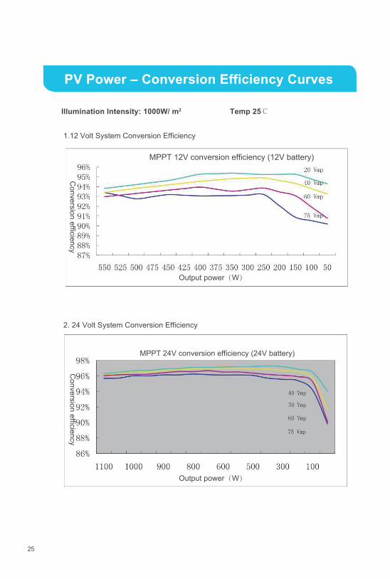
PV Power – Conversion Efficiency Curves
25
Temp 25℃
MPPT 12V conversion efficiency (12V battery)
1.12 Volt System Conversion Efficiency
2. 24 Volt System Conversion Efficiency
Illumination Intensity: 1000W/ m2
Conversion efficiency
Conversion efficiency
Output power(W)
MPPT 24V conversion efficiency (24V battery)
Output power(W)
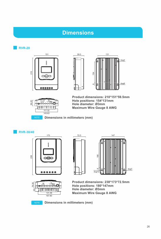
ROV-20
Dimensions
26
Dimensions in millimeters (mm)
Dimensions in millimeters (mm)
RVR-30/40
RVR-20
NOTE
NOTE
Product dimensions: 210*151*59.5mmHole positions: 154*131mm
Maximum Wire Gauge 8 AWGHole diameter: Ø3mm
Product dimensions: 238*173*72.5mm Hole positions: 180*147mm
Maximum Wire Gauge 8 AWGHole diameter: Ø3mm
151 59.5 131
4xφ3
210
154
8 4xφ9
6xφ8
117.32
69.2
0 13.87
143.63
173 72.5 147
4xφ10
238
180
8 4xφ3
6xφ8
131.46
78.3
022
18
167.60

Renogy reserves the right to change the contents of this manual without notice.
2775 E. Philadelphia St., Ontario, CA 917611-800-330-8678