Embed Size (px)
Citation preview

Prepared by Helacol Services Ltd for the Health and Safety Executive 2016
Health and Safety Executive
Review of small wind turbine construction instructions and specifically for structural supports and foundations
RR1081Research Report


Helen M BoltHelacol Services Ltd Ledger House Forest Green Road Fifield Maidenhead SL6 2NR
This research investigated the possible role of weaknesses in small wind turbine construction instructions in the potential for structural collapse associated with the structural supports and foundations. Build instructions relating to nine turbines of differing scale and design were obtained with industry cooperation. Analysis showed that although the stipulations were generally clear, the overall design intent of the details and criticality of certain aspects were not conveyed. As ostensibly similar details can be made to function intentionally in radically different ways, it is concluded that deviations from the required procedure could be better guarded against if the design intent and criticality were made explicit in each case. This would particularly benefit installers working across a range of products from different manufacturers. Site practices could also be improved to achieve the required bolt tensions and structural grout integrity with greater surety.
Some good practices in assurance processes for the siting checks, engineering assessments and construction were seen including photographs and records of as-built details. Wider adoption should be encouraged to improve confidence in integrity.
Factors potentially contributing individually or in combination to failures were identified in a number of areas. Known concerns about the potential under-prediction of fatigue design loads using the simplified design method in the small wind turbine standard (IEC 61400-2) were underlined. Given the transition period to 2017/19 until more stringent controls apply to new and ongoing certifications, coupled with issueson the prior exclusion of the tower and foundation from the scope of certification in the UK, industry groups such as RenewableUK’s Small and Medium Wind Strategy Group who made a positive contribution to this study, are called on to renew their efforts encouraging manufacturers to proactively review the adequacy of existing and future certified installations.
This report and the work it describes were funded by the Health and Safety Executive (HSE). Its contents, including any opinions and/or conclusions expressed, are those of the authors alone and do not necessarily reflect HSE policy.
Review of small wind turbine construction instructions and specifically for structural supports and foundations
HSE Books
Health and Safety Executive

© Crown copyright 2016
First published 2016
You may reuse this information (not including logos) free of charge in any format or medium, under the terms of the Open Government Licence. To view the licence visit www.nationalarchives.gov.uk/doc/open-government-licence/, write to the Information Policy Team, The National Archives, Kew, London TW9 4DU, or email [email protected].
Some images and illustrations may not be owned by the Crown so cannot be reproduced without permission of the copyright owner. Enquiries should be sent to [email protected].
Acknowledgements
The authors would like to acknowledge the contribution of many parties to ensure a balanced picture could be built during this study although the identity of manufacturers and installers is necessarily confidential for commercial reasons. In addition the facilitation and technical input from the following people and organisations is acknowledged with thanks: RenewableUK - Chris Streatfeild (Director of Health & Safety), Louisa Coursey (formerly Small & Medium Wind Development Manager) and the Small & Medium Wind Strategy Group, Microgeneration Certification Scheme, MCS product and installer certifiers, Insurance companies and brokers
ii

iii
CONTENTS
CONTENTS iii
GLOSSARY iv
KEY MESSAGES v
EXECUTIVE SUMMARY vii
1 INTRODUCTION 1
1.1 CONTEXT AND IMPLICATIONS 1
1.2 PROBLEM DEFINITION 4
1.3 STUDY OBJECTIVE AND APPROACH 8
1.4 REPORT STRUCTURE 8
2 RESEARCH FINDINGS 9
2.1 COMMERCIAL CONTEXT AND FUTURE TRAJECTORY 9
2.2 DESIGN AND INSTALLATION PRACTICE 11
2.3 CASE STUDY EXAMPLES 27
3 PRACTICE IMPLICATIONS AND RECOMMENDATIONS 33
APPENDIX A – EXTRACTS FROM REFERENCE STANDARDS RELATED TO SMALL WIND TURBINE STRUCTURAL SUPPORTS AND FOUNDATIONS 35
REFERENCES 47

iv
GLOSSARY
BIS Department for Business, Innovation and Skills
BWEA British Wind Energy Association (later became RenewableUK (RUK))
FIT Feed in Tariff – UK Government subsidy for renewable energy devices
HAWT Horizontal Axis Wind Turbine
HSE Health & Safety Executive
IEC International Electrotechnical Commission (standards making body)
NMS National Measurement System
RUK RenewableUK – industry trade association
SWT Small wind turbine
VAWT Vertical Axis Wind Turbine
.

v
KEY MESSAGES
A number of small wind turbines (SWT) had collapsed in unexceptional winds due to failure at their base supports, so this study was commissioned by the Health & Safety Executive (HSE) to review the adequacy of the build instructions supplied by wind turbine manufacturers to installers. Examining information provision and constructability in the context of turbine design and certification practices in consultation with the SWT industry, has led to the following conclusions:
Providing adequate strength and resilience in the structural supports and foundation to SWTs requires: realistic estimation of the loads; correct calculation of structural performance; and construction practices that achieve the design intent. Shortfalls in one or a combination can lead to premature and sudden failure. With the industry’s rapid growth in the last decade, design standards, certification practices and site experience have matured and the framework of requirements today (IEC 61400-2 Edn 3, MCS 006 and the RenewableUK Small Wind Turbine Standard) addresses many of the potential areas for concern with recent past practices. It is important that the significance of these changes is widely understood, particularly during the periods of transition (to 2017/19) where practices may be inconsistent.
Design standards and guidance now warn of potential un-conservatism in the ‘simplified design method’, emphasise the need to account for turbulence effects and avoid proximity to structural resonances, and counsel that the cumulative effect of borderline component compliances may be inadequate overall. The scope of product certification under MCS and RenewableUK standards will now cover the ‘sample’ structure and foundation support system. Although project certification is not practised for SWT (in the sense of the conformity testing and certification wind standard IEC 61400-22), industry guidance will reinforce the importance of site specific investigation and re-engineering if necessary. As certification links the SWT to a designated ‘Class’, it is required that geotechnical, topographic and environmental factors at an installation site fall within the Class design envelope. By implication, these strengthened requirements reveal some of the weaknesses that singly or collectively may have affected the degree of conservatism in existing installations.
SWT monopoles are typically provided with a flanged base which can be installed readily over a standard ring of suitably sized threaded anchor rods (bolts) embedded in a reinforced concrete pad foundation. The SWT can be positioned with a combination of washers and nuts, then torqued to fix the connections. Slight variations in the use of levelling nuts, underbase grouting, and sequence and level of torqueing can intentionally but radically alter the load transfer mechanisms and, in particular, fatigue resistance. Although drawings and specifications were found to be generally clear on the requirements, the critically and function was not explained. In other circumstances this would not be required but given installers deal with different turbines and manufacturers with ostensibly similarly (but possibly fundamentally different) support connections, and that the familiar mechanical connections elsewhere function differently, stronger explanation of the critical elements for the foundation supports is strongly recommended. In addition, industry agreed improvements in practice to achieve more consistent, reliable results are recommended for:
o Underbase structural grouting with improved shuttering / containment solutions, higher level outflow points etc to ensure complete grouting
o Inducing required tension in anchor bolts directly without reliance on torque measurements affected by frictional effects

vi
o Locking top nuts securely in position (whether with lock nuts or proprietary systems)
o Provision of anchor bolts and fixings to the required standard and number as part of the installation package (in the few cases where this is not already done).
For assurance on the standard of SWT installations, parties from customers, insurers and Government agencies awarding subsidies have relied heavily on the MCS accreditation of turbine products and installers. However, the scope covered by certification depends on the governing regime (so pre 2014 structural supports and foundations were not required to be included) and certifier practices (e.g. acceptance of the simplified design method). None routinely covers each project specific installation. Furthermore, aspects of construction and compliance with specifications cannot be readily inspected retrospectively (e.g. foundation construction, underbase grout quality, embedded nuts, torque sequencing etc), yet these can fundamentally affect the safety and integrity during operation. Good practice in assurance and ownership of construction standards by manufacturers has been demonstrated with interactive reports recording critical sign-off (engineering approval of site specific suitability), key facts (torque levels by connection) and giving specific supporting photographic evidence (pre-concrete pours, grout material labels). Satisfactory completion is in some cases a pre-requisite of the turbine Activation Key eventually being released. This supplements the increasing use of manufacturers’ web portals to enforce use of latest drawings and specifications. Efficient ways to strengthen the assurance of installation and construction practices are recommended as they have the potential to improve confidence and reduce financial risks for all parties whether manufacturer, installer, insurer or turbine owner.
HSE’s focus on the build instructions for SWT structural supports and foundations has served to open a network of related design and assurance issues. There appears to be no single cause explaining failures, although the rapidity with which technologies were brought into the subsidised market may be assumed to have put pressure on the then burgeoning supporting standards and certification systems. The issues have generally been recognised by industry groups and addressed in revised systems. However, future pressures on the market will come from the quashing of subsidies further reducing the viability of exploiting SWT technology. There is no clear ‘target’ for a corrective HSE campaign and the more fruitful approach to sustaining improvement may be to encourage trade bodies such as RenewableUK to renew their emphasis on the legacy issues raised in this study, taking them forward through existing channels as appropriate. For HSE inspectors, the issues listed may be raised with individual duty holder contacts as they occur, recognising that the relevance varies by manufacturer and turbine in relation to legacy issues for certain turbines and current and future practices for others.

vii
EXECUTIVE SUMMARY
Background
There have been a number of incidents in recent years involving the structural failure of ground mounted small wind turbines in which the turbine has collapsed or blown over in unexceptional conditions. Investigations by the Health & Safety Executive (HSE) suggested the failures were characterised by the turbine towers failing at their base supports. Furthermore the investigations identified potential shortcomings in the method of installation or the misinterpretation of the installation instructions provided by the turbine manufacturer.
These ‘small’ wind turbines (SWT, technically defined* as having a swept rotor area less than 200 m2) are typical of individual installations providing power to agricultural farms. They also generate sufficient energy (typically 5-50kW) to suit small businesses and public buildings (such as schools, offices, small factories etc) where public access is likely with a resultant risk of injury if structural failure were to occur.
The project
This study was commissioned by HSE’s Safety Unit† to identify any issues relating to small wind turbine construction more generally so that proportionate action can be taken to improve construction and tower installation standards and prevent turbine failures. The objective is to reduce the risk of injury and avoid the costs to business associated with failure incidents.
The approach, specified in HSE’s Statement of Service Requirements, was to obtain and assess sets of build instructions from a range of turbine manufacturers (~10). These were then analysed, benchmarking the information against the stipulations of relevant codes and standards. The build instructions were assessed in terms of:
Contracting policies and controls
Format and clarity of information provided to installers and constructors
Ease/practicability of compliance
Quality control and assurance.
Consideration was also given to the changing requirements for past, current and future installations and to the context of the demands from intermediaries who certify and insure small wind turbines. Findings emerging in the course of the study turned attention additionally to the structural design concepts, associated standards and their interpretation.
Findings
Tubular monopoles are the most common structural form for mounting small wind turbines. At height, the turbines capture wind energy more cost-effectively with minimal losses from ground * The international Electrotechnical Commission (IEC) sets out international standards for all electrical, electronic and related technologies. The suite of IEC 61400 standards covers wind turbines. Part 2 specifically applies to small wind turbines. † The Safety Unit (SU) is HSE’s strategic point of contact for product safety, supply and technical policy issues in relation to work equipment. It has overarching/cross-cutting responsibility for safety issues and product law arising from EU supply legislation. SU is a key partner for central Government Departments BIS and DfT in attending and contributing to European Commission technical and enforcement Working Groups / Committees. It participates in a number of European Standards group and develops and sponsors research on product safety issues. SU provides advice, guidance and support to other parts of HSE and to market surveillance authorities such as Trading Standards.

viii
interference effects. The rotating turbine and winds impinging on the structure generate static and cyclic loads which need to be transmitted through the monopole, and via the structural supports to the foundations to prevent failure due to overload or fatigue. The most common solution is to provide a reinforced concrete pad foundation for strength and stability with an embedded ring of threaded vertical bars (bolts). These protrude above ground level so the monopole tower with pre-prepared holes in the base flange can be inserted over the bars, levelled, and fixed in position. In broad principle the same approach is adopted for lighting poles and larger wind turbine structures.
However, the way the support connection is formed can vary and proper understanding and construction are essential for safety and integrity. Two connection approaches are adopted but the final configurations are visually similar. Furthermore threaded bars / bolts are inherently poor in fatigue because of the stress-raising notch effect even in rolled threads. However, in almost all cases the potential for sub-standard components is now avoided by manufacturers/tower designers supplying a kit of parts including structural elements, bolts, nuts and washers, template rings etc.
In the first approach, bolts are (over)sized to take the full fatigue loading – the tower flange is levelled on a full complement of nuts/washers and top nuts are tightened to clamp the flange firmly in position. This is important to prevent the bolts coming loose and the tower moving under fluctuating load exacerbating the fatigue loading. The gap below the tower flange may or may not be in-filled to protect the bars.
In the second case, more typical for larger SWT, the tower flange is levelled on a few underside nuts (e.g. on 3-5 bars). The gap below the flange is then filled with a structural grout and, once set, top nuts on all the bars are torqued. This is to compress the grout and concrete alongside the bars whilst they are pre-loaded with a locked-in tension. This enables, future fatigue loading to be shared between the concrete and steel, minimising the proportion of load the bolts have to withstand. For the connection to work as intended, it is vital that the bolts are free for the pre-load to develop, that the grouting is competent without voids, and that the torque introduces the intended loads.
Reports have provided evidence of bolts loosening, incorrect numbers of bolts being applied affecting load distribution, and poor grouting with voids, leading to failure.
The small wind turbine design standard, IEC 61400-2, allows a simplified design method for conventional horizontal axis wind turbines, in place of the full aero-elastic modelling and testing required for larger turbines (swept area >200m2). The most recent edition (Edn 3, December 2014) includes a caution that the approach may not be conservative, a finding based on experience, theory and practical demonstrations. This means there may be legacy under-design issues for existing structures and these may persist as transition arrangements for certification permit the use of the previous edition until 2017 (for new certifications) and 2019 (for product developments in process at the point Edition 3 was introduced).
Furthermore, the scope of certification under the Microgeneration Certification Scheme (MCS), on which Government subsidies, insurers and others apparently rely, has not previously included the turbine tower or foundations. It will only be as the transition period expires that this aspect will formally be covered.
The study has revealed, however, that some Certifiers have recognised the limitations with the simplified method and the importance of structure and foundation integrity, such that their own practices and services offer attention to these aspects.

ix
Nevertheless, the duration testing of SWT that is done as part of product certification does not replicate in-service support conditions, as standard (larger) test beds are used for which each manufacturer supplies an adapter plate to enable their smaller wind turbines to be connected.
In relation to standards and certification, it is worth noting that many civil engineering structures are designed on a prototype case by case basis whereas SWT are covered by product certification, typical for mechanical and electrical equipment used in identical form in multiple locations. To deal with the possible variations of wind, turbulence and geotechnical conditions at different sites, SWT designs are certified for a given ‘Class’ and a site specific application should comply with the relevant design range to be deemed safe and appropriate. Most SWT in the UK are not installed directly by manufacturers but by authorised dealers/installers. The MCS scheme separately certifies turbine products and the competence of installers for that type of work. The latter process should sample how installers deal with example sites but certification is not done on an individual project basis‡. The degree of control exercised by the manufacturer and/or installer over site suitability varies. Whilst there are clear long-term advantages of correct siting (on safety and output performance), there are short term disincentives in cost and time e.g. in engaging specialists for intrusive site investigations and engineering work, or responding to conditions imposed by third parties such as planners with respect to height, exact location etc which can affect the loading on, and resistance afforded by, the ‘standard’ certified design.
Conclusions
The conclusion from these findings is that problems potentially leading to SWT structural support and foundation failure can arise singly or in combination due to issues with:
Site specific investigations, and if necessary, re-engineering to account for local determinants of foundation integrity, wind loading and turbulence
Methods for calculating loads to be transmitted through the structural supports to the foundation and in particular potential lack of conservatism in the IEC 61400-2 ‘simplified’ method
Construction uncertainties such as:
o Lack of understanding about the design intent and construction imperatives, particularly where installers work with different turbine manufacturers and types
o Imprecise relation between applied torques and bolt / connection induced loads due to frictional effects
o Quality of tower under-flange grouting and insufficient skill and rigour in grouting procedures
Applicable reference standards and potential confusion with transition arrangements until 2017/19 for bringing towers and foundations within scope alongside different approaches being offered earlier as good practice by professional certification bodies that may or may not be taken up by manufacturers.
The existence, scope and style of assurance mechanisms for individual installations.
Recommendations
In formulating recommendations it has to be recognised that the changing pattern of renewable energy subsidies is suppressing the small wind market severely. Whilst this does not affect the importance of safety, it does have a bearing on the proportionate and cost-effective approach for introducing improvements within the scale of current and likely future activity.
‡ The provision for project certification included in IEC 61400-22 is not adopted within the MCS scheme.

x
In relation to construction aspects the (possibly hidden) uncertainties over whether the actual construction satisfies the design intent could readily be addressed by:
Manufacturers adding clarification to their drawings / installation procedures so they not only set out the required components, materials and sequencing but also explain the design intent and underline why strict adherence is essential as not all aspects will be intuitive (e.g. more nuts in certain circumstances may weaken the foundation).
Manufacturers, possibly working together, developing improved structural grouting procedures for the congested under-flange zone (covering formwork, highest point outlets, pumping output, flange edge embedment etc) drawing on best practice in other sectors
Manufacturers reviewing the translation of required torque levels to intended bolt tensions and the efficacy of their nut locking procedures
Manufacturers working with installers, look at best practices in the assurance of project specific installations considering, for example, web portals for up to date information, report sheets confirming engineering sign off for the location, record sheets for as-built data supported by intermediate construction photographs and records of materials such as concrete batches and grout mixes. This could be done on an individual basis or collectively sharing best practices in project assurance.
Intermediaries such as insurers have placed store in the MCS certification perhaps not realising the scope and limitations of the scheme. It would be in their own and customer interests to have assurances on project specific issues with improved controls.
Concerns over the use of the simplified design method and the duration of transition arrangements are probably best dealt with through the trade association, RenewableUK, and, in particular, their Small and Medium Wind Strategy Group (made up of manufacturer, structural designer, installer and certifying body representatives). They are already aware of the issues and active in dialogue as a group with MCS and through individual representation on the IEC 64100-2 standards committee. The circumstances vary by turbine in relation to design intent, operational history etc but it may be appropriate to recommend each manufacturer reviews the potential applicability of the concerns to their business activity and implements checks or improvements as appropriate. It is understood that through the UK Government (BIS) and the National Measurement System (NMS) further work to quantify inadequacies in the simplified method is underway and this would complement the approach. In a similar design vein, a common approach could also be recommended in relation to determining bolt fatigue resistance using Eurocode 3 Part 9 or alternative industry standards.
The issues highlighted above provide the basis for a topic checklist for HSE inspectors to include in duty holder contacts. The range of potential issues involved to different degrees in relation to different turbines / projects, suggests a focused campaign or individual topic-based inspection would not be fruitful. It is therefore recommended that the importance of the issues is underlined with key industry bodies and they are further picked up on should specific inspections arise. While the transition to more exacting industry standards is underway, the potential for inadequacies in past practice to undermine the safety margins against fatigue failure in the structural supports of some existing installations may remain. Manufacturers whose designs may be affected should be urged to prioritise a review for installations with high levels of public access.

1
1 INTRODUCTION
1.1 CONTEXT AND IMPLICATIONS
‘Small’ ground-installed wind turbines (SWT) are the focus of this study. These are formally defined in the IEC 61400 Part 2 standard11 as “wind turbines with a rotor swept area smaller than or equal to 200 m2, generating electricity at a voltage below 1000 V ac or 1500 V dc for both on-grid and off-grid applications”. This implies a hub to tip blade length in a horizontal axis wind turbine (HAWT) of less than 8 metres.
In order to understand the nature of turbines at the centre of this study, Figure 2 reproduces a scaled illustration from RenewableUK’s Small & Medium Wind Strategy report(1) and superimposes the approximate span of ‘medium’ to ‘small’ (and ‘very small / micro’) turbines. There is a degree of overlap at the small / medium wind interface as the turbine technology affects the relationship between rotor swept area (on which formal definitions are based) and capacity (shown). This study is only concerned with ground mounted installations not the roof mounted very small / micro turbine illustrated in the bottom left photograph.
Small wind turbines are generally single turbine installations principally owned by private individuals, agricultural farms or small enterprises for on-site consumption only exporting unused capacity to the grid. At the other extreme, large wind farms owned by major utility companies may comprise many tens of turbines, of the order of 160m high, each generating some 5 - 6 MW and specifically installed to provide power to the grid (turbines 220m high and with a capacity of 8MW are now available).
Figure 1 Turbine scales1
Past failures
State of industry
Generi
Figure 2 Schematic illustration of micro-small-medium wind turbines sizes and scale1
This study does not quantify the likelihood (or rarity) of failure – it acknowledges that such failures have occurred and therefore the event is foreseeable. It takes its direction from HSE investigations of three separate failures which, as stated in the project brief, pointed at “shortcomings in the methods of installation or the misinterpretation of the installation instructions provided by the turbine manufacturer” as contributory factors. The question being addressed is whether the same issues could arise for SWT more generally, based on a review of a
Very small / Micro Small Medium

2
sample of manufacturers’ build instructions. The purpose of this report is then to set out measures to help prevent such collapses occurring, thus reducing the risk of injury and costs to business associated with failure.
A separate research study for HSE2 has examined the risks from turbine failure although the emphasis was seemingly on large wind turbines (where, for developments over 50MW capacity HSE has a role as a statutory consultee as part of the planning process). Amongst potential failure modes the report did include ‘tower collapse’ noting:
“The collapse of the tower and rotor system is very rare occurrence for modern wind turbines. This type of failure could occur if the tower fastening system was not installed properly, possibly due to improper torquing of the base or yaw system bolts. In this case the tower would fall over as it loosened and then became severed at the base flange. The rotor would then impact the ground with the potential to scatter debris over an area significantly larger than the machine itself.”
It should be noted that examples of other forms of integrity failure can be found in press reports - principally turbine fires which can escalate to cause collapse, and turbine blades fragmenting and falling. These are covered in the report2 quoted above, and feature more prominently than tower collapse in its analysis. The underlying causes are completely different, in the first case related to the over-speed controls and braking systems in extreme winds, and the second to lightning strikes in storms, for example. Preventative measures have been advanced in terms of improved turbines from the mechanical engineering perspective and lightning protection. No further attention is paid to these forms of failure in this report.
The type of collapse illustrated in Figure 3 (taken from a press report) relates to the toppling of an otherwise apparently sound turbine structure such that the tower becomes detached at the foundation base. Furthermore, such failures have occurred in “unexceptional conditions” as opposed to high winds or other extreme conditions.
Figure 3 Image from a press report in September 20143 showing a toppled turbine

3
To place the current study in context, it is also relevant to reflect on the growth and economic position of the small wind industry. Although considerations of safety should not be directly affected, inevitably technical maturity and experience, market (in)stability etc have a bearing on things like industry standards, business/contracting strategies, workforce competence etc which underpin safe practices.
The growth of the renewable energy sector is a response to the need to reduce carbon emissions and find more sustainable sources of energy. Electricity generation from small scale wind power has been practised for some 40 years but the growth has principally been since 2005 with 248MW of small and medium wind capacity installed in the UK4. In parallel with developments in turbine design, other renewable energy solutions such as photo-voltaic solar energy have become more efficient and affordable. Nevertheless renewable energy installations typically require a significant upfront capital investment taking many years of energy savings to recover so, in order to incentivise investment and help the Government meet its international climate change commitments, grants and ‘Feed in Tariff’ subsidies have been offered to make installations more attractive to individuals, educational establishments and small businesses with improved rates of return.
The focus and level of subsidy have changed over time, in part responding to take-up but also to reflect different Government / budget policies. This has significantly influenced the market so, whereas many SWT were once being installed (some 2,000 in 2013), suddenly the take-up has reduced (only six turbines less than 50kW installed in the UK in April 2014 according to RenewableUK) as subsidies favoured solar schemes over wind and also made SWT far less attractive investments than medium installations. Where businesses in the small wind sector had matured investing in staff and systems, participating in industry standards making etc, recent times have seen a rapid move to out-sourcing in place of retained capacity and a number of manufacturers and businesses in the supply chain going into administration or being taken over.
Another influence on the small wind industry is the power and expense of the planning process. Small (as opposed to micro) wind turbines require specific planning approval which can take time and require investment in specialist reports. In granting approval, planners can impose conditions affecting the siting or screening of turbines which prospective owners may be inclined to accede to rather than protract or potentially jeopardise permission by resisting. However, relocation has the potential to bring different ground conditions or load (interaction) effects from those accounted for in the initial design.
Neither the market conditions nor permissioning processes should impact on the safety levels sought or achieved. However, the mechanisms for effecting any improvement do need to reflect the ways the small wind sector is currently operating and may operate in the future.

4
1.2 PROBLEM DEFINITION
It is important to define those aspects of small wind turbines that are and are not within the scope of this study. Internet-sourced schematic diagrams are used in this section to illustrate the scope.
Figure 4 presents a horizontal axis wind turbine (HAWT) showing the component mechanical and electrical systems which convert the wind-driven rotation of the blades into electrical power for export. The tower elevates the assembly to capture the wind efficiently, minimising effects from interference with the ground. The tower has to be anchored into the ground with a connection system that can withstand static, dynamic and fatigue effects of the environmental loads acting on the assembly and tower, as well as interaction effects generated and transmitted through the structure.
The proprietary turbine technologies affecting the power production and efficiency are primarily in the blades and machinery within the nacelle. The structural supports and foundations are secondary in that respect. However the stiffness of the base fixity inevitably affects the degree of movements and frequencies of the whole system, and thus the forces and moments to be transmitted.
The diagram shows the typical concept of anchor bolts connecting a flange at the base of the tubular tower into a mass concrete base. It is the adequacy of design and construction practice in these structural supports and foundations (red ellipse) which are the focus of this study.
Figure 4 Schematic of a horizontal axis wind turbine (HAWT) http://zeroemissiondevelopments.com/wind-energy-what-is-it/
Figure 4 illustrates the horizontal axis configuration which has been more extensively and successfully deployed than vertical axis wind turbines (VAWT) to date – see Figure 5 for a conceptual comparison of the two types. Although offering advantages like the main components (gear box, generator etc) being at ground level, inferior efficiency compared with HAWTs combined with concerns about underperformance and reliability of early products, mean relatively few VAWT are in service5.
Figure 5 Comparison between horizontal and vertical axis wind turbine concepts http://machinedesign.com/sustainable-engineering
However, VAWT technologies are being actively advanced with new small to medium wind products going through certification en route to market. Development work includes attention to
Nacelle

5
the structural supports and foundation design necessary to take out lateral forces, shock loads and resonance effects.
The in-service failures which prompted this study all related to HAWT and given their current market dominance, that configuration is the main focus of this study. However, emerging VAWT examples are also covered to provide the comparison on technical features of future deployment.
The schematic turbine diagram in Figure 4 shows a tubular ‘monopole’ tower. The alternative configuration, particularly for early / micro turbines, was a lattice or truss tower (see Figure 6). Tubular towers are structurally more efficient, require less maintenance than the bolted lattice frameworks and have been considered to make less visual impact and so are far more widely adopted. The spread, multi-point bases for a lattice tower are also significantly different. Given their market dominance and the fact that all the investigated failures related to tubular towers, lattice structures are excluded from this study.
Figure 6 Comparison between truss (lattice) and tubular tower configurations http://www.cleanenergybrands.com
The way in which most turbines are supported and anchored to the foundation is shown in Figure 7 which combines web images from a number of turbines – the scale obviously varies with the turbine size. In essence an excavation is made into which a three-dimensional reinforcement cage (square grid) and ring of anchor bolts is fixed. The bolt ring is connected to annular templates with nuts top and bottom to ensure the bars/bolts remain in place. The foundation is then concreted leaving the ring of bolts protruding. The top template is removed and the turbine tower or lowest tower section is slotted over the bars, levelled and fixed in position with a combination of nuts and washers, torqued to a specified value. The gap between the flange and concrete foundation may, or may not, be grouted and the exposed bar beneath the connection may, or may not, be wrapped in protective tape against corrosion. The top nuts may involve a second ‘locking’ nut or other proprietary lock nut solution. The nuts may, or may not be, torqued again once the grout (if used) has set.
An important factor in the integrity of the connection is the way load is induced and transmitted from the tower to the foundation. Figure 8 shows examples of three connections – red indicates an element in tension, the blue curves indicate zones in compression. In the first case (1), the flange rests / is levelled on the underside nut. Tightening the top nuts has clamped the flange placing the short length of bar in tension. Discussed in more detail in Section 2.2.7, the critical location for fatigue is just below the lower nut (solid arrow) and is governed by the fatigue properties of the threaded bar. Threaded bars are inherently poor in fatigue due to the stress raisers even in rolled threads. Whether or not the gap is filled with grout, pre-tension cannot develop down the length of the bar as torqueing the top nuts simply draws the lower nut against the flange.
If the nuts are not sufficiently tight or are able to work loose (depending on the initial torques and/or locking mechanisms deployed) the flange can move, the increased flexibility in turn will affect the overall structural movements and load distribution, exacerbating the cycling / fatigue effects and leading to progressive failures around bolts in the ring.

6
Figure 7 Stages in the structural support construction: excavation; fixing reinforcement and anchor bars; concreting leaving anchor bars protruding; positioning tower/flange over bolts,
fitting nuts and torqueing (images sourced from different websites)
(1) (2) (3)
Figure 8 Alternative pre-tension (red) and compression (blue arcs) in anchor bolts connecting a turbine tower flange to the concrete foundation, based on construction method
In the second case (2), the bar has no lower nut, levelling of the flange being achieved on other bars (or with some other support mechanism). However, the gap is ‘tightly’ filled with a structural grade grout before the top nuts are torqued. The effect is to place the whole bar down to its base anchorage into tension with the surrounding cementitious materials being compressed by the tower base flange. So long as the load transfer can be effective, this is a very resilient connection and (as explained in Section 2.2.7) limits the proportion of fatigue loading carried by the anchor
grout grout

7
rod / bolt. However, if the grouting were of low strength or incomplete (with voids, possibly hidden) the load sharing could not develop. Similarly if lower nuts were present, the stressing would be local to the plate without mobilising the stiffness of the surrounding concrete (detail (3) in Figure 8).
Figure 8 provides sections through connections but it can be readily appreciated that ostensibly similar looking connections from above can perform very differently structurally depending on their original construction. Furthermore the situation for an individual bolt is shown and different approaches may be adopted around the bolt ring (e.g. levelling on a few nuts as in (3) but with full load sharing being developed for the majority as in (2)). In such instances there must be variations in the necessary displacements and force distribution around the flange / bolt ring.
Details of the failure investigations carried out by HSE are confidential. Furthermore, the sources of failure differ in each case but contributory factors appear to have included:
Local topography adding to turbulence and wind shear loading not accounted for in the design
Reliance on components and structural details which are inherently poor in fatigue
Potential mis-application of design standards including use of the simplified load model outside the bounds of its stated applicability leading to under-prediction of design loads
Deviations from the prescribed installation process preventing bolt tension and compression in the surrounding concrete and grout being developed, exposing the rods to fatigue for which they were not designed, by inter alia:
o Inclusion of additional support nuts (beyond the number specified) under the tower flange during construction
o Poor quality grouting under the tower flange using cosmetic not structural grade grout.
Given the foregoing description of the way bolted anchor connections may, or may not, work some of these issues may not be surprising. Bolts, particularly in the un-prestressed condition of the first example (1) in Figure 8 are inherently poor in fatigue and section sizes need to be adequate to withstand applied loads. Variation (2) is structurally more efficient, however, it does bring with it some construction uncertainties and risks if the anticipated resistance is to be mobilised.
It must be assumed that these challenges for developing robust designs are deemed to be offset by the considerable advantage of the bolted flange connection in that a standard tower can be supplied and erected speedily.
It is relevant to note that the pace of development in the SWT industry with overseas and UK designed products being brought to market. Those designs have changed with time and for a number of manufacturers different ‘generations’ of the same turbine model offer different structural details and resilience. Similarly codes and standards have advanced and practices for certification evolved. This means that residual issues might exist for a number of turbines in a fleet but it cannot be concluded that all generations would be similarly affected and it would be unwise to generalise conclusions from specific cases.

8
1.3 STUDY OBJECTIVE AND APPROACH
The objective of this study was to identify any systemic reasons why fit for purpose structural supports and foundations may not be constructed for SWT. There was a particular focus on the build instructions provided by manufacturers and the ways in which work may be carried out by turbine installers and other third party contractors. In the event, it was not always manufacturers but sometimes installers (with permission from manufacturers) who were best placed to provide the information to the study team, reflecting the current supply chain mechanisms.
The HSE requirement was to procure a maximum of 10 (minimum 8) sets of build instructions from manufacturers which could be critiqued against industry standards. The work has therefore included a review of these reference standards and liaison with bodies who administer and execute certification activity against those standards. Intermediaries such as insurers were also consulted given their common interest in means to ensure failure does not occur. A key consultee was the trade body, RenewableUK (RUK), through whom information about the project was conveyed to industry. In particular the RUK Small & Medium Wind Strategy Group was initially briefed by the project team, then consulted on emerging findings. As a group their cooperation was constructive and individually the contributions of experience and insight were invaluable. With their counsel the scope was expanded to cover the implication of design standard shortcomings and transitional arrangements in certification. In addition construction practices for the structural supports and foundations for more lightly loaded gantry columns and more heavily loaded large wind turbine foundations are referenced for comparison.
1.4 REPORT STRUCTURE
The report is broadly structured to satisfy HSE’s 1-3-25 required format with 1 page of key message, an executive summary of around 3 pages, and 25 or so pages in the main body of the report plus appendices. Beyond this Introduction (Section 1), Section 2 delivers the research findings in terms of the current and future market size, SWT design standards and certification, the technical approaches to securing towers to foundations, and the information from consultees on custom and practice in the industry. A comparison is made in Section 2.3 of the turbines and build instructions for the nine contributions to this study – many of the details are commercially sensitive so the collation necessarily describes the range to obscure the identity and/or issues for individual turbines. Appendix A provides supporting details for the (changing) reference standards. The final section in the main body of this report (Section 3) sets out the basis for the study recommendations and key messages.
9
2 RESEARCH FINDINGS
2.1 COMMERCIAL CONTEXT AND FUTURE TRAJECTORY
Although recognised as an energy resource for decades, the technology developments and motivation to exploit wind energy more widely has come about through the 1990s and into the 21st Century in response to concerns around climate change, the depletion of fossil fuels and the quest for more sustainable sources of energy. The 1997 Kyoto Protocol formally committed the UK and international governments to restrict the emission of greenhouse gases from 2005. The legally binding targets to be achieved for 2010 (calculated on the basis of average emissions 2008-2012), in turn provided the imperative for a focus on renewable energy sources. The Doha amendment to the Protocol extends the commitments for a further period from 2013 to 20206.
The political imperative has translated into fiscal policies offering grants and (since April 2010) feed-in tariff (FIT) payments to incentivise investments. The large capital investment and long payback period for many renewable energy schemes mean that market forces alone would not have been sufficient for the targets to have been achieved. However, the subsidy levels within the Levy Control Framework (LCF), have been varied by governments over time and between and within technologies – in the case of wind, the relative FIT payment for small wind has fallen relative to larger scale technologies affecting the attractiveness of small wind investments.
In recent years, the growth rate and resulting capacity in ‘small wind’ in the UK has only been exceeded by the USA and China from a worldwide perspective according to a 2014 report from the World Wind Energy Association7. However, with the UK Government now confident its 2020 commitments will be achieved, it is signalling that subsidy schemes may be curtailed8 with a view to future projects resting on economic viability in their own right§.
The significance of the above facts when considering the safety of installed and future SWTs is illustrated in the following graphs. Figure 9 demonstrates how the elimination of favourable FIT rates for small and micro wind in late 2012 aligning rates with medium wind up to 100kW (indicated by lines on the graph), has suppressed the market with growth predominantly at medium to large scales (symbols). Figure 10 underlines this in terms of the number of new installations each year. Since 2012 there has been sharp decline in micro and small wind deployment with growth in the medium to large sector.
§ As of 1 October 2015 changes to the ROO-FIT scheme (>50kw installations) mean that tariff rates cannot be pre-agreed on a development and will only be determined once installed – see www.ofgem.gov.uk. This further adds to the risk and uncertainty for prospective owners/developers.

10
Figure 9 Variation of Feed in Tariff rates for different scale turbines over time9 showing total capacity of turbines in small and medium capacity bands in years 2010-201410
Figure 10 Annual number of deployed UK small and medium wind turbines10

11
2.2 DESIGN AND INSTALLATION PRACTICE
2.2.1 Design and Installation Basis
Design
The primary elements of proprietary wind turbines comprise the blades and mechanical and electrical components designed to be efficient in capturing and converting the wind energy into electrical power (see Figure 3)4. The tubular tower provides structural support to the turbine elevating it to sufficient height to capture consistent wind flow without degradation from ground interference effects. As such the structure is a passive component but needs to be designed to transmit the loads that result from the turbine in addition to environmental loads impinging directly on the tower. Innovation within the tower structure can be introduced with a view to making installation and/or maintenance more flexible, efficient and safer, for example with shorter sections bolted together in place of one tube or incorporating a ‘tilt-up’ hinged mechanism to enable the turbine to be assembled at ground level before being rotated to the vertical. The overall integrity finally relies on the tower being fixed to the ground at its base with sufficient strength and resilience to withstand the extreme and fluctuating loads through its operational life with a satisfactory level of reliability.
The challenge is that where the proprietary turbine mechanism is to be supplied repeatedly and consistently, at each location the local topology may still affect the wind (loading) effects and the ground conditions may require a customised foundation.
The SWT design process involves a number of steps (see also Section 2.2.2), namely:
Determining the ‘actions’ in terms of wind speeds, turbulence etc acting on the turbine – for the generic design, Classes I to IV define the conditions in which a particular turbine can be used. The turbine selection is matched to the environmental parameters at a given site.
Determining the profile of static and dynamic forces that result and the way in which they are transmitted through the structure to the ground** – design loadcases based on a range of normal operating and extreme operating conditions are specified and three options are permitted to determine the resulting forces – a simplified method with equations detailed in the standard, aero-elastic modelling which requires the bespoke modelling and calculation or physical testing and measurement.
Engineering a ‘standard’ base / foundation fixings to ensure the configuration and component sizes are adequate.
In order for the final SWT to perform as intended, it is then important that the construction and installation specification, drawings and manuals reflect the design accurately and unambiguously and that the works are carried out in accordance with those documents. This simplifies the site specific application so that detailed design is not required for each location. However, it is essential that assumptions and reality are confirmed to be consistent.
** Particular concerns were raised by contributors to this study about the potential for tower top thrust not being controlled as anticipated in design. Without sufficient protections, forces associated with (sudden) braking, brake failures and overspeed can result in over-stress and/or significant vibrations. These in turn affect the actual loading transmitted through the foundation/connections. Instances of designer/manufacturers instrumenting towers but being unable to correlate design and measured loads were noted. This is a significant area of work in its own right, beyond the scope for investigation in the current study.

12
Installation
There are a number of potential models for distributing small wind turbines for the market. For example:
Manufacturers operating directly or through appointed dealers sell directly to customers with the manufacturers performing their own turn-key installations.
Manufacturers operating through appointed dealers and approved installers (trained by the manufacturer) provide turbines to customers through those third parties who perform the installation.
Manufacturers operating directly or through dealers sell turbine ‘kits’ directly to customers for installation themselves or using local contractors.
By far the most common model encountered in this study was the second option where additionally the turbine product and appointed installers were formally approved (see Section 2.2.3). Mention was made of manufacturers performing their own installations but generally as the exception or with reference to past practices - it may be concluded that the commercial advantages of not having to maintain an in-house installation workforce and the growth in competence in the installer market would be driving factors. The final approach was not encountered in the present study of ground mounted turbines although it may be expected to persist at the micro end of the market. Examples of turbine installers involving third party groundworks contractors were noted but this may be seen as an entirely sensible approach given the equipment and skills needed for excavation and reinforced concrete construction which are quite different from the mechanical and electrical skills of turbine installation technicians.
2.2.2 Small Wind Turbine Standards
The International Electrotechnical Commission (IEC), under the auspices of Technical Committee 88 (TC88) has developed a suite of international standards for Wind Turbines designated IEC 61400. They provide the basis for design, quality assurance and certification. Support structures come within scope††. Part 2 of the standard (IEC 61400-2)11 deals specifically with small wind turbines (SWT), defined as those with: A rotor swept area smaller than or equal to 200 m2, generating electricity at a voltage below 1 000 V a.c. or 1 500 V d.c. for both on-grid and off-grid applications.
The standard “is concerned with all subsystems of SWTs such as……. support structures, foundations………” which are the aspects relevant to this study. Part 2 is introduced as being similar to the main standard IEC 61400-1, but “it does simplify and make significant changes in order to be applicable to small wind turbines”.
The IEC 61400 suite of standards also includes Part 22 for ‘Conformity testing and certification’ (IEC 61400-22)12 but this is not a normative‡‡ reference within IEC 61400-2. Edition 1.0 of IEC 61400-22 was issued in May 2010 and remains the current version.
†† TC88 Scope: To prepare international standards for wind turbines that convert wind energy into electrical energy. These standards address design requirements, engineering integrity, measurement techniques and test procedures. Their purpose is to provide a basis for design, quality assurance and certification. The standards are concerned with all subsystems of wind turbines, such as mechanical and internal electrical systems, support structures and control and protection systems. They are intended to be used together with appropriate IEC/ISO standards. TC88 is actively working on the standards and, as of January 2016, a Part 6: Tower and foundation design (applicable to large turbines rather than SWT) had reached the First Committee Draft stage. It is also understood that a re-organisation of the whole IEC 61400 suite is planned longer term. ‡‡ A ‘normative’ reference within a standard is designated such if it is indispensable (compulsory) to the correct application of the standard.
13
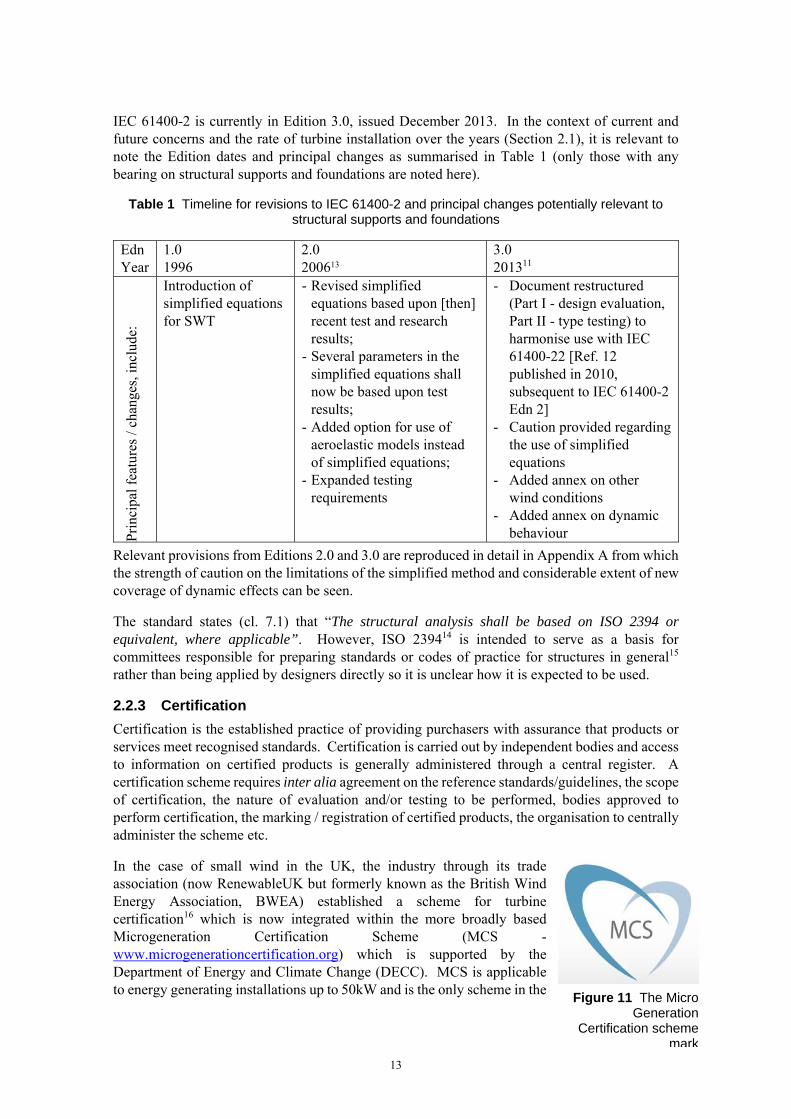
IEC 61400-2 is currently in Edition 3.0, issued December 2013. In the context of current and future concerns and the rate of turbine installation over the years (Section 2.1), it is relevant to note the Edition dates and principal changes as summarised in Table 1 (only those with any bearing on structural supports and foundations are noted here).
Table 1 Timeline for revisions to IEC 61400-2 and principal changes potentially relevant to structural supports and foundations
Edn Year
1.0 1996
2.0 200613
3.0 201311
Pri
ncip
al f
eatu
res
/ cha
nges
, inc
lude
:
Introduction of simplified equations for SWT
- Revised simplified equations based upon [then] recent test and research results;
- Several parameters in the simplified equations shall now be based upon test results;
- Added option for use of aeroelastic models instead of simplified equations;
- Expanded testing requirements
- Document restructured (Part I - design evaluation, Part II - type testing) to harmonise use with IEC 61400-22 [Ref. 12 published in 2010, subsequent to IEC 61400-2 Edn 2]
- Caution provided regarding the use of simplified equations
- Added annex on other wind conditions
- Added annex on dynamic behaviour
Relevant provisions from Editions 2.0 and 3.0 are reproduced in detail in Appendix A from which the strength of caution on the limitations of the simplified method and considerable extent of new coverage of dynamic effects can be seen.
The standard states (cl. 7.1) that “The structural analysis shall be based on ISO 2394 or equivalent, where applicable”. However, ISO 239414 is intended to serve as a basis for committees responsible for preparing standards or codes of practice for structures in general15 rather than being applied by designers directly so it is unclear how it is expected to be used.
2.2.3 Certification
Certification is the established practice of providing purchasers with assurance that products or services meet recognised standards. Certification is carried out by independent bodies and access to information on certified products is generally administered through a central register. A certification scheme requires inter alia agreement on the reference standards/guidelines, the scope of certification, the nature of evaluation and/or testing to be performed, bodies approved to perform certification, the marking / registration of certified products, the organisation to centrally administer the scheme etc.
In the case of small wind in the UK, the industry through its trade association (now RenewableUK but formerly known as the British Wind Energy Association, BWEA) established a scheme for turbine certification16 which is now integrated within the more broadly based Microgeneration Certification Scheme (MCS - www.microgenerationcertification.org) which is supported by the Department of Energy and Climate Change (DECC). MCS is applicable to energy generating installations up to 50kW and is the only scheme in the
Figure 11 The Micro Generation
Certification scheme mark

14
sector. Significantly, since 2009/10 eligibility for subsidies and payments under the FIT scheme (see Section 2.1) is contingent on the installers and products being MCS certified17. Installations generating >50kW are required to have accreditation under the Government’s Office of Gas and Electricity Market (OFGEM) Roo-FIT scheme 18.
In addition to general scheme requirements for installers and products, current standards specific to micro and small wind on the MCS website are:
Installer standard: MIS 300319 Product standard: MCS 00620 RenewableUK Small wind turbine standard21
The MCS 006 product standard has to be used in conjunction with the RenewableUK standard which provides supporting detail. Both are dated January 2014 following immediately on from the issue of IEC 61400-2 Edition 3. In turn the RenewableUK standard links, with few exceptions, to the requirements in IEC 61400-2. Notes relating to potentially novel turbines and to inverters are also given. None of the standards cites IEC 61400-22 on conformity testing and certification.
The RenewableUK standard21 replaces an earlier BWEA edition from 2008. It continues to exclude the electrical provisions of IEC 61400-2 (Section 9) from mandatory certification but it does now require certification of the support structure and foundations (per IEC 61400-2, Section 10). Previously, and therefore for many existing SWT, this aspect was not mandatory and a turbine certification cannot be assumed to have covered these aspects.
Although it is noted above that certification in accordance with IEC 61400-22 is not required under MCS, the provisions are instructive to review in terms of the four types of certification distinguished, namely:
A component certificate – covers a major wind turbine component (eg blade, gearbox)
A prototype certificate – covers a wind turbine not ready for series manufacture at a specific site
Type certification: procedure by which a certification body gives written assurance that a wind turbine type conforms to specified requirements
Project certification: procedure by which a certification body gives written assurance that one or more specific wind turbines including support structures and possibly other installations are in conformity with requirements for a specific site.
The scope of a certification regime must be proportionate in effort and cost to the potential risks in terms of scale and severity. It seems that for small wind, project by project certification is not practised in this way although type (product) certification is required. It will be seen (Section 2.3) that the extent to which project / site specific aspects are reviewed for compatibility with the ‘generic’ foundation assumptions varies – in some cases left with installers but in others, manufacturers require formal feedback for each location.
2.2.4 Application of Standards under Certification
Transition Arrangements
Section 2.2.2 notes the introduction of Edition 3.0 of the SWT standard IEC 61400-2 at the end of 2013 addressed weaknesses in the Edition 2.0 standard (e.g. inappropriate application of the simplified design method) and provided clearer alignment with IEC 61400-22 on product testing

15
and certification. Immediately afterwards new versions of the MCS and RenewableUK product standards were issued to call up Edition 3.0 as noted in Section 2.2.3.
However, the process of product development and certification can take many years, and rather than impose an immediate change, these UK certification schemes provide for a transition period. In principle such arrangements are not unusual when non-safety-critical changes are introduced in standards particularly when related to products with a lengthy development phase. However, these effectively delay the requirement for full compliance with the new IEC 61400-2 until 15 January 2017 for new product certifications and until 15 January 2019 for turbines that had been certified before 15 January 2014. Manufacturers may, of course, opt to apply the new standard sooner but the transition period is potentially one of confusion in terms of which IEC 61400-2 edition ‘certified’ status relates to. Figure 12 illustrates the milestones and timescales involved.
Figure 12 Timeline based on MCS 006 Issue 2.120 showing transition arrangements for certification compliance with IEC 61400-2 Edn 3.011
Testing and certification to IEC 61400-22
As noted in Section 2.2.2, the elements and approach to testing and certification in IEC 61400-22 are not mandatory aspects in applying IEC 61400-2. In addition, the UK SWT certification schemes described in Section 2.2.3 deal only with product (and installer) certifications. These schemes do not reference IEC 61400-22 and they focus on the product certification without reference to separate project certification accounting for local conditions.
It is appropriate that certification schemes should be proportionate and IEC 61400-22 sets out detail for wind turbines in general including larger wind turbines for utility supply. Even if not formally required in a certification standard, it may be expected that approved certification companies would be familiar with relevant standards and voluntarily adopt aspects as good practice.
However, it cannot be inferred that the existence of IEC 61400-22 for product testing and certification means it is applied under the current MCS standards for SWT.
Even for large wind the role of IEC 61400-22 is said to be linked more to due diligence or an assurance required by third parties (such as investors) in relation to performance rather than safety matters. However reference to the Service Specification from DNV-GL both for type and project certifications22 to IEC 61400-22 relates only to the Parts 1 and 3 of the standard for medium-large and offshore wind turbines confirming that practice is not to apply it to SWT.
It should not be concluded from this that project specifics are overlooked for SWT. The class-based design certification (see Section 2.2.1) ties the foundation to specific wind regimes and the generic foundation is related to specific ground condition characteristics and properties. There

16
is, however, potential variability outwith the certification process in the way any deviation from the design conditions is handled, related to the degree of control exercised by the manufacturer through the supply chain.
Reported Certification Experience
This study involved direct consultation with individual certification bodies (of both products and installers) as well as collective discussions with industry bodies such as the RenewableUK Small and Medium Wind Strategy Group where these bodies are represented. These flushed out a number of clarifications about the way certification is carried out and opinion, based on experience and observations, about potential sources of past and future issues with structural supports and foundations.
Observations from prior incidents included failures associated with undersized bolts and overload at connections at the top of the tower which it was judged had been rectified with redesign of components and/or introduction of new control mechanisms. Some argued that although more easily rectified than support base failures, the top structure over-loads pointed at a potentially common cause due to design loads being under-estimated. Anecdotal information also noted that attempts to instrument towers/turbines were not matching predictions.
Overseas failures where bespoke / lightweight towers had been adopted were attributed to the greater flexibility introduced. Although not specific to UK applications, it underlines the potential significance of changed structural stiffness.
In relation to failures more generally, product certifiers noted that they would not necessarily be informed (even if it was a turbine type they had certified) if the matter were linked to installation practices or dealt with via insurance rather than a matter linked to aspects of the certification scope per se.
MCS confirmed that once a product or installer is certified, MCS don’t follow up directly. The only way they would know of an issue would be if they had feedback directly from a customer. Any contractual related aspects would be pursued under the Renewable Energy Consumer Code23 - RECC is a subsidiary operation of the Renewable Energy Association aimed at guaranteeing a high quality experience for consumers wishing to buy or lease small-scale energy generation systems for their homes. The scheme is backed by the Trading Standards Institute. Companies carrying the logo (Figure 13) have committed to complying with the code. The framework for consumer protection has been subject to recent legislative change (October 2015) to strengthen and streamline protections in the area22.
Figure 13 The RECC trading standards mark
The way site-specifics are dealt with was an area of uncertainty for certifiers. Product certifiers were clear that a specific engineering assessment would be needed as this is not covered by the ‘generic’ certification of a tower type. Installer certifiers confirmed their focus was on the competence of installers and that that is assessed by sampling work on individual sites. It was noted that although good installers would challenge the suitability of sites / magnitude of loading this could delay the process and so had some inherent disincentives. A view expressed by installer certifiers was that site specifics and topography and potential for turbulence were possible sources of accelerated fatigue and they cited pressure on installers from clients and planners and the competences needed to understand the significance.

17
The transition from BWEA to RUK standards was seen to be significant in early 2014 with the tower and foundations coming in to the certification scope. However, the exclusion of these aspects to date (and the transition arrangement to 2017/19) mean that certification has not contributed to assurance of these aspects.
Furthermore the duration testing as part of product certification is undertaken at designated test sites where permanent foundations large and robust enough for testing larger scale towers are used with the manufacturer of small wind devices being required to provide an adaptor plate. The tests therefore do not provide accurate representation of the service conditions for the turbine supports and foundations.
Product certifiers mentioned recognised concerns with use of the simplified design methods and instances of failure demonstrating the under-prediction of loads. It was commented by one that use of the simplified method was now rarely seen (particularly with the growth in VAWT for which it does not apply) and that aeroelastic modelling had been adopted by them as certifiers following the IEC 61400-2 change in 2014.
Industry safety guidelines
An unpublished input to this study was a recent draft of the SWT safety guideline24 under-development within RenewableUK working groups. It aims to provide background and a route map to key health and safety legislation and risk management relevant to small wind projects. It includes a summary of particular challenges in addressing safety issues for small wind projects taking into account the diversity of size, design and configuration of turbines.
In relation to risk management, one of the key considerations highlighted is site specific turbine design, noting this is “A critical aspect in determining the actual level of safety and integrity of a small wind installation will be its suitability taking account of the particular environmental conditions and constraints of the chosen site. Turbine design and the selection for a given location need to explicitly take account for example of maximum survival gust speeds and turbulence intensity.
In addition, engineering assumptions are highlighted, warning about complete reliance on IEC standards and the MCS in isolation and explaining: This is because while individual calculations may indicate the component or system is ‘compliant’ or within a ‘safety tolerance’, the aggregated effect of too many ‘borderline’ results could mean that the safety integrity of the turbine or system as a whole could be compromised. Therefore, while it is important to be guided by the applicable standards, it is sensible to apply a precautionary approach when the engineering or scientific evidence to validate a calculation or design decision could be limited or incomplete.
It would appear these guidelines are an attempt to strengthen the focus on areas that the relatively new IEC standard, with limited field experience, may not have fully addressed.
IEC 61400-2 Simplified design method limitations
With one submission a manufacturer included their (confidential) specification used to provide tower top loads to the tower designer which, with the addition of direct tower loads, determine the foundation design requirements. Although their own practice is to adopt aero-elastic modelling, a comparison with predictions from the simplified method permitted in IEC 61400-2 was made for this study (Edition 3 now includes a caution as noted in Section 2.2.2).

18
The aeroelastic modelling gave a fatigue equivalent tower top thrust nearly 3 times the fatigue equivalent load from the simplified model. The picture is complicated by: the (smaller) simplified method load applying for two orders of magnitude more cycles during the installation design life; considerations of variable amplitude loading; and the possible effects of constant amplitude fatigue limits. In addition the comparison will be affected by the choice of fatigue design line§§ (See below for comparison between BS7608 and EC3 representations).
Nevertheless the contributor argues that the simplified equations under-predict the fatigue loads (relative to aeroelastic modelling) by nearly a factor of 3. This should be a significant concern in general applications as the principle of allowing a simplified design method is that the benefit of simplicity is offset by a conservative calculation method.
Previous Government-funded research25 has also looked at the feasibility of revising the simplified load model to achieve a set of more robust and relevant equations. Recommended areas for improvement included additional loadcases particularly fatigue. An international effort was proposed (in 2012) to deliver a structured programme of testing and analysis related to representative wind turbine designs but it is understood that as of October 2015 this has not been progressed.
Structural design standards
For designers having determined the forces and fluctuating loads to be transmitted from the turbine, via the structure to the foundations (IEC 61400-2 methods refer), recourse must be made to engineering design codes and standards to determine the component and section sizes to provide the necessary resistance and endurance with adequate levels of confidence. In the UK, principal references are:
Eurocode 3 (EC3): Design of Steel Structures, 2005
- BS EN 1993-1-1 General rules and rules for buildings
- BS EN 1993-1-8 Design of joints
- BS EN 1993-1-9 Fatigue
However, some manufacturers have also referred to:
BS7608. Code of practice for fatigue design and assessment of steel structures, 2014 (although the 1993 version existed for current SWT designs)
BS7608 gives methods for assessing the fatigue life of parts of steel products that are subject to repeated fluctuations of stress. It is “applicable to all areas of industrial application that are not covered by other British Standards containing fatigue assessment rules” so strictly does not apply to steel structures which have been covered by EC3 since 1993. Indeed, steel and civil engineering structures are listed as a specific exclusion from the applicability of BS7608. It is however a reference used by the wind industry more generally and, significantly, the 2014 edition is a complete revision including new rules for bolts and new cumulative damage rules.
§§ An S-N curve is a standardised plot of the stress range (S) corresponding to different numbers of cycles (N) resulting in fatigue failure. Miner’s rule collates the cumulative effect of fewer numbers of cycles (n) at different stress levels (s). The component is deemed to survive the variable amplitude loading if the sum of the proportions of life (n/N) used at each stress level are less than unity. The summation represents the degree of fatigue ‘damage’ or life consumed.

19
EC3, first introduced in 1993 is accompanied by a number of authoritative ‘guides’26,27, frequently used by designers including the Steel Construction Institute’s ‘green’ book on moment resisting connections28 which includes the principles for designing structural base plates and anchorage whether for simple joints or moment resisting connections. Fatigue provisions in the relevant standards reference bolts as well as welded connections. In EC3 bolts are assigned to Class 36 but it is noted that because the fatigue data do not really match the fatigue strength curves (and to avoid non conservative conditions), the designated curve is taken as the one which corresponds to available fatigue failure data at 2 million cycles (Clause 9.7.3). The provisions of Part 9 also included a deleterious ‘size’ effect applicable for sections greater than 30mm. BS7608 has a size effect from a thickness of 25mm. The forms of S-N curve also differ (with a slope change at different points) so different fatigue lives would be determined for the same applied stress ranges.
This would appear to be a further source of inconsistency in determining the endurance of turbine support connections and one where an agreed industry approach would be beneficial in avoiding errors.
2.2.5 Insurance Provision
A certification scheme in essence is intended to ensure quality and minimise risk of failure. It provides assurance for purchasers and others without the technical know-how or means to make their own judgements.
Other bodies such as insurers have a parallel interest in failure being avoided so approaches were made in the course of this study to general insurance brokers, specialist underwriters and umbrella bodies such as the Association of British Insurers (ABI) to determine what demonstrations they may require. Despite repeated approaches neither underwriter responded in any detail. Brokers were more forthcoming and their experiences and approaches inevitably reflect the requirements from specialist underwriters with whom they generally place the insurance.
Conditions required by one broker included the turbine and installer being MCS approved with the design complying to British Standards.
Owners’ insurance claims were said most typically to be associated with low/lost revenue due to turbine maintenance issues and down-time. The quality of service support from manufacturers had therefore become a primary indicator for insurers and now they would refuse insurance of certain turbines because of production and maintenance issues, seeing this as a warning more generally.
Information was also submitted to this study indicating a class action is being prepared on behalf of agricultural owners of 15-20kW turbines in relation to installation, key parts failure, service levels and future service contract failures and the underperformance of SWT29.
There was general recognition amongst insurance brokers of turbine collapse(s) but as a rare rather than preventable risk. It was also noted that failure associated with installation would be referred back through the manufacturer and the insurer would not necessarily even be aware.
From one insurer there was a comparison between the information required on solar-PV and wind turbine insurance proposal forms. For solar PV information on product compliance with both IEC standards and MCS, together with assurance on an MCS installer and an independent structural report on the adequacy of the structure to which roof-mounted panel are to be fixed. The turbine proposal form requires information on ‘type certification’ but no other structural or site specific data. Evidence of engineering inspection is required for equipment relating to lifting and mechanical equipment safety regulations.

20
It was noted that for sub-50kW turbines, the premiums are ‘small’ so there would be no site survey or other reporting requirements imposed in the insurance process. The same insurer did however note that they are now insisting on blade lightning protection being in place which may be seen as a response to in-service failures from other causes and industry learning. This demonstrates the influence insurers can wield in relation to a recognised problem and effective solution.
2.2.6 Other Intermediaries
Before investing in a renewable energy scheme a prospective purchaser may also seek references from peers. Small wind turbines are actively promoted within farming rural communities for on –farm use and grid export. The National Farmers Union (NFU) offers members a Farm Energy Service*** which includes ‘approved suppliers’. At the start of this study three suppliers were listed but only one on a refreshed website as of August 2015. The firm(s) supply and install wind turbines manufactured by third parties. Discussion with the NFU Farm Energy Service indicated that suppliers apply to NFU to go on the approved list and screening is based on financial due diligence on a company’s standing / robustness, with no technical / performance audit around installation practices or the products supplied.
2.2.7 Technical Basis for Bolted Tower Supports and Foundations
Section 1.3 outlined the configuration of typical structural supports connecting the turbine tower and foundation. In this section the underlying principles of the way such bolted connections work and connections are designed are explained.
Bolted Connection Principles
In order to understand the design issues and significance of construction practices for the integrity of tower supports it is useful to review the engineering principles.
Bolted connections have significant practical advantages for wind turbines in terms of speed of assembly, piece small transportation and construction, dismantling etc. Mechanical components are frequently bolted together. Considering the structural support of SWT, tower designs frequently comprise tubular sections of different diameters bolted together at flanged connections. In addition the lowest tower section may be bolted to pre-installed anchor bolts to provide the structure-foundation connection (Figure 4 and Figure 7). In all cases fixity is provided by nuts on the threaded bolt in contact with the flange. There are differences however in the nature of the clamped surface or surfaces and the degree of pre-tension that may or may not be introduced into the bolts, in whole or part. These aspects are discussed further below in generic terms, then in relation to SWT connections.
Bolted connections may be required to transmit static or fluctuating (fatigue) loads. Bolt capacities for static loading are based on the net area within the threaded section. The fatigue resistance of bolts is more complex to determine.
Fatigue failure has three stages, crack initiation, crack propagation under fluctuating loads and then rupture when the remaining section is inadequate to take the applied load. Steel as a material can withstand certain levels of reversing loads without cracks initiating and thus providing infinite fatigue endurance. However the thread forming process in bolts (even for rolled threads) introduces stress raisers and discontinuities such that cyclic loads of sufficient level can lead to the initiation of cracks which subsequently propagate leading to fatigue failure. Welded connections are similarly affected and empirical evidence has determined that for design purposes
*** http://www.nfuonline.com/membership/farmer-grower/member-services/nfu-farm-energy-service/farm-energy-service/

21
the inverse relation between stress range and number of cycles can be characterised similarly (the S-N curve).
The resulting failure surface through a bolt is distinctive with ‘beach’ marks as the crack propagates under fatigue loading until a fracture of the remaining section occurs.
Of course, if a bolt is damaged or subject to corrosion in any way, this may leave stress raisers leading to early crack initiation or defects or cracks which can propagate more quickly than anticipated. Coastal locations present particular concerns with reported bolt failures, so measures such as channels/chasing in the concrete to aid drainage, maxicoating / denso taping / painting where possible to prevent corrosion, and regular inspection are needed.
The location of fatigue failures in a bolt also needs to be considered. The nut serves to transmit loads into the bolt but the distribution along the trapped threads is not even and the stresses are concentrated closest to the connection making this the typical site for failure to initiate in an un pre-stressed bolt30 - Location 1 in Figure 14. If, however the connection comprises two nuts and these are over-tightened putting a pre-tension in the length of bolt between the nuts, the critical zone for fatigue cracking shifts outside the connected zone (to Location 2 in Figure 14). The effect is to give a more even distribution of load transfer within a nut and between the two nuts31. The full fatigue capacity of the bolt such as it is can then be utilised without suffering the degradation due to the nut-bolt interface.
Figure 14 Potential failure locations in a double nut connection depending on level of pre-load
A further benefit is that the critical zone moves to outside the connection length. Although access to the underside of the tower flange is not easy, it possibly provides a basis for crack detection as part of an inspection / maintenance regime. This could not be done within the connection length.
This tightening of nuts to either side of a single flange, is the principle adopted in many tower support connections (Figure 8, picture (1)). The lower nut on the anchor bar serves initially as a levelling nut for positioning the structure. The upper nuts then fix the base flange in position and the subsequent torqueing of these nuts serves to ensure the full fatigue strength of the bolts is available. However, there is the potential for shear at the base of the tower to move and loosen the nuts with time but this can be accounted for in determining initial pre-load levels and maintenance (torque checking) schedules. It should be noted that any loosening not only takes the critical fatigue site back to within the connection length but also permits additional movements and different load patterns around the base than designed for, resulting in conditions that can lead to a progressive and catastrophic failure bolt by bolt within the array.

22
The engineering of such anchor bolt connections is quite different from the design of more typical flange to flange connections (as at intermediate points up the tower). Here the nuts are to either side of the two flanges (from upper and lower sections of the tower) on short connecting bolts. If the connections were not pre-stressed the flanges would pry apart under loads transmitting the full fluctuating load through the bolts. By pre-tensioning the bolts (by torqueing the nuts) the large stiff flange sections are compressed together. As forces act to separate the sections the compression between the flanges reduces but is not reversed and the bolts, which are significantly less stiff, see only a small increase in tensile load (see Figure 15). For compatibility, the movements have to be equal (a strain controlled situation) so the loads are distributed according the relative stiffnesses. As long as the pre-loads are designed appropriately and introduced correctly, the fluctuating bolt loads are minimised and bolt fatigue failure can be eliminated.
Figure 15 Joint diagram showing the sharing of applied load between the pre-tensioned bolt and stiff clamped plates (taken from boltscience.com)
At the base anchor connection of an SWT there is only one flange bearing on the nut and thence bolt so the action and role of pre-stress is completely different and should not be confused. The tightening of the nuts to either side of the base plate does not protect the bolt from failure, it merely shifts the critical location into the un-pretensioned length of the bolt beneath the connection. Furthermore the fluctuating loads still have to be transmitted through the bolt below the flange attachment. Given the inherently poor fatigue performance of threaded bolts and the considerable loading uncertainties, this can require large diameter bolts to limit the stresses to be below the fatigue endurance threshold.
However, there can be situations where more efficient use can be made of the anchor bolts by tensioning them along their full embedded length, bringing the concrete base into action (Figure 8, picture (2)). This requires the void above the foundation slab under the base tower section to be filled with a structural (load bearing) grout. The long anchor bolts can then be tensioned from the top nuts along their embedded length inducing compression in the surrounding concrete. As for the conventional bolted connection, subsequent fluctuations in load will be transmitted primarily through varying compression in the stiff concrete leaving only small stress variations in the bolts. However, in order for the long bolts to be pre-tensioned only top nuts can be in place. If nuts are present on both sides of the base plate/flange, any applied torque will only tension the short connection section (Figure 8, picture (3)). The foundation system would therefore need to comprise a minimal number of anchor rods with levelling nuts, the remainder having a single top nut applied with the bars tensioned to provide the system resistance to applied loads. (Comparison with the approach for large wind turbines is made below).
The fluctuating loads and shear across the various bolted connections mean the potential remains even for tensioned connections to loosen. The extent is extremely difficult to predict. This

23
loosening not only exposes the bolts to higher stress ranges but also changes the effective stiffness of the structure and in turn the distribution of loads to be transmitted through the structural supports and foundations. Inspection and maintenance regimes therefore form an important part of ensuring ongoing integrity.
Options are available to minimise the potential for loosening and the double nut solution is one that may be considered. In this two nuts (sometimes one slim and one full depth) are used on each side of a connection. The thin nut is installed first and tightened to 25-50% of the intended torque. It is then held in place with a spanner to prevent further rotation while the full nut is installed and torqued to the full value. This largely means the load is transferred via the large nut but one thread at the nut interface has the thin nut bearing on one face and the thick nut on the other. This effectively jams the nuts in position preventing any relative movement. However, the efficacy of the system and safety are dependent on the correct sequencing and careful attention to load levels (e.g. to prevent threads being stripped and tensile failures ensuing).32
Figure 16 Two nut locking method to prevent loosening (taken from boltscience.com)
The turbine manufacturers are focused on exploiting the benefits of their proprietary mechanical and electrical systems. The support structures and foundations are essential components but designed to different engineering codes and requiring structural and civil engineering expertise. Specialist tower manufacturers have generally established business alliances delivering design and construction expertise in these areas. As part of this study enquiries were made with one such company, whose name is synonymous with a frequently observed form of bolted flange connections. It was confirmed that this aspect of the design has received renewed attention from them in recent months including detailed finite element analyses. The current recommendations are to rely on over-designing bolt sizes to prevent fatigue becoming an issue and to use ‘wedgelock’ washers with a single nut to prevent connections loosening. Any pre-tension applied is across the flange thickness, not tensioning the full bolt length (Figure 8, picture (1)).
Wedgelock washers33 are a proprietary product from Nord-Lock a Swedish company with a base in the UK (see Figure 17). Bolted joints are secured with tension instead of friction locking fasteners subjected to extreme vibration or dynamic loads. The system uses a pair of lock washers with cams on one side and radial teeth on the opposite side. The cam angle "α " is larger than the
Jam location in thread at nut interface
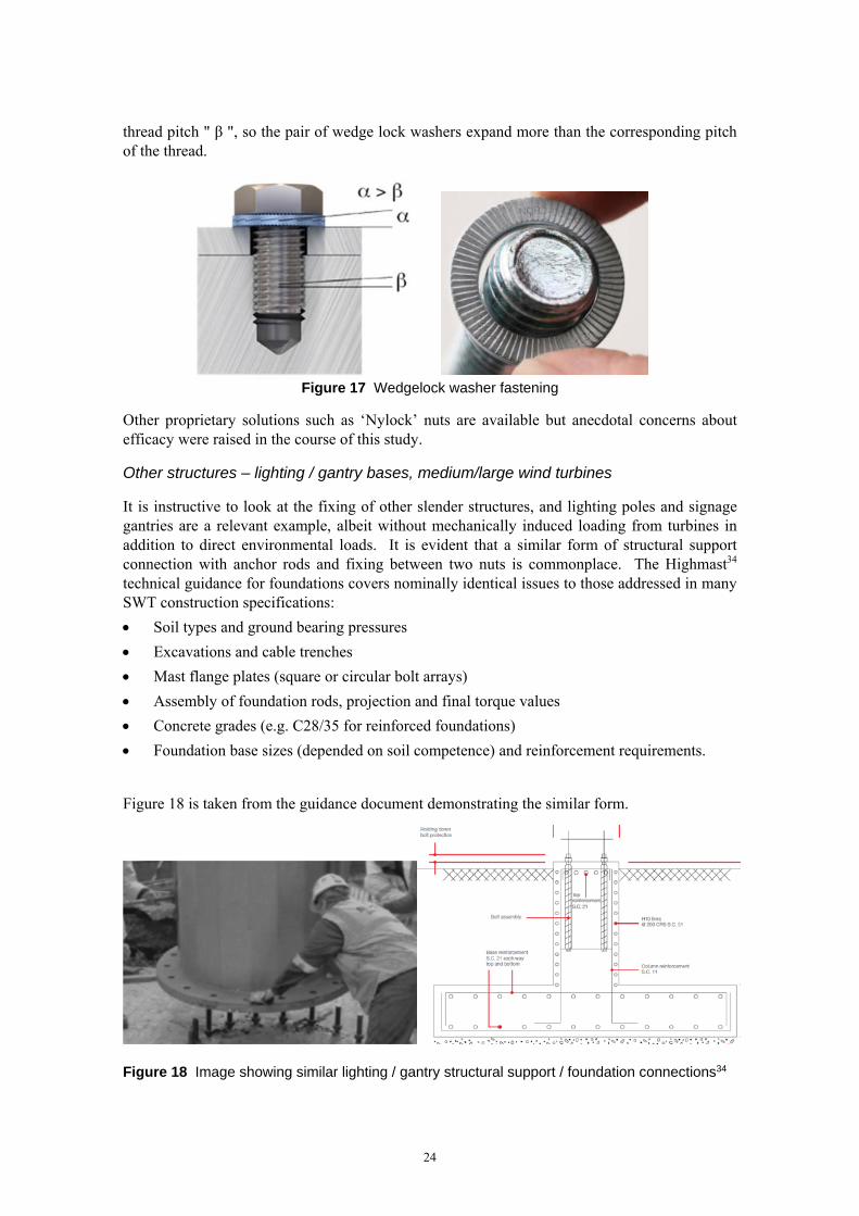
24
thread pitch " β ", so the pair of wedge lock washers expand more than the corresponding pitch of the thread.
Figure 17 Wedgelock washer fastening
Other proprietary solutions such as ‘Nylock’ nuts are available but anecdotal concerns about efficacy were raised in the course of this study.
Other structures – lighting / gantry bases, medium/large wind turbines
It is instructive to look at the fixing of other slender structures, and lighting poles and signage gantries are a relevant example, albeit without mechanically induced loading from turbines in addition to direct environmental loads. It is evident that a similar form of structural support connection with anchor rods and fixing between two nuts is commonplace. The Highmast34 technical guidance for foundations covers nominally identical issues to those addressed in many SWT construction specifications:
Soil types and ground bearing pressures
Excavations and cable trenches
Mast flange plates (square or circular bolt arrays)
Assembly of foundation rods, projection and final torque values
Concrete grades (e.g. C28/35 for reinforced foundations)
Foundation base sizes (depended on soil competence) and reinforcement requirements.
Figure 18 is taken from the guidance document demonstrating the similar form.
Figure 18 Image showing similar lighting / gantry structural support / foundation connections34

25
A significant body of anchor bolt connection design research and testing comes from the lighting / gantry area. In Michigan (USA) in 1990 two gantries came down in independent incidents, both found to be due to fatigue failure and since then Texas A&M University has undertaken a number of significant studies on behalf of the state transportation department. Initially research verified earlier findings specific to anchor bolts and configuration35. This included the finding that tightening the double-nut connection (one nut to either side of the clamped base plate / flange) 1/3 of a turn-of-the-nut beyond snug tight significantly improved fatigue life and moved the failure location to the outside of the connection as discussed above. The more recent research supervised by the same team36 showed, based on testing and analysis, that a standard of 1/6 turn-of-the-nut or refusal of tightening by specified methods was recommended, provided a minimum of 1/12 turn-of-the-nut was achieved. The conclusions are of course specific to the range of bolt sizes and grades tested but confirm the practicability of a definitive standard being achieved.
This approach based on fractions of a turn from a ‘snug tight’ position††† differs from the torque measurement approach apparently used for SWT in the UK. The problem with the latter is that friction at the various interfaces can add to the resistance making the actual force in the bolt uncertain. The physical turn of a nut requires a set elongation of the bolt which (depending on thread pitch, bolt diameter etc) implies a specific force. It is notable that from the authors’ experience, bridge engineering applications rely similarly on defined turns of bolt heads. In offshore engineering, high strength Macalloy bars are subjected to direct tension using hollow ram jacks so that the required loads and distribution can be assured (Figure 19). It is noted that the Macalloy bar product is being promoted by the manufacturers as an anchor solution for (large) wind turbines37. The brochure (and supporting university testing) claims superior fatigue performance due to the thread form compared with standard bolts such that a more favourable fatigue curve can be justified even for the critical tension-bending condition at the turbine base. Figure 20 gives examples of the anchor bars and protrusion from the foundation reinforcement cage from two Swedish wind farm examples.
Figure 19 Use of bolt tensioner on large wind turbine38
††† The condition when the nut is in full contact with the base-plate. Different researchers adopt different definitions such as “the full effort of a workman on a 12 inch wrench”36 or “a torque of 271Nm (200 ft lb)”31

26
Figure 20 Large wind turbine foundation example using Macalloy bars 37
As can be seen from the above figures, anchor cage solutions are used in large wind farms comparable in principle to the anchor solutions used for SWT. In these cases the annulus below the tower flange and concrete base is grouted with a high quality material so that once the bolts/anchors are tensioned, the dynamic loads from the tower are transferred by the grout to the foundation structure.
Figure 21 Under-base grouting on a large wind turbine
This anchor cage solution has largely replaced the ‘embedded ring’ concept where a tubular section with a lower T flange was concreted into the base and the upper tower section was bolted on to the upper flange with short bolts (as for flanged connections in tapered tower structures) - Figure 22.
Figure 22 Embedded ring installed within the large wind turbine foundation prior to reinforcement and concreting (note the vertical bars around the ring form part of the reinforcement
cage and are not anchor bolts)39
Figure 23 Section showing form of foundation
degradation associated with embedded rings
However, it is reported39 that these were prone to failure within the concrete (typically due to under-design of the loading conditions or poor quality concreting). The consequent cracking and movements (Figure 23) led to additional loading. Complex remedial schemes introducing an additional flange and reinforcement ring have been implemented.

27
Considering further the anchor cage solution used in large turbine structures (similar in principle to the SWT solution), the tower flange is levelled on screwed supports independent from the anchor bars (Figure 24) so that once the underbase has been grouted, all the anchor bars / bolts are tensioned through the depth of the stiff concrete / grout foundation. Furthermore it can be seen that the inner face of the grout channel is formed as part of the initial concreting. This serves to ensure complete under flange grouting and the containment may additionally provide tri-axial constraint, enhancing the stiffness and strength of the grout annulus in compression.
Figure 24 Preparation for installing a large wind turbine lower flange onto the anchor bolts showing the screw support for levelling40
2.3 CASE STUDY EXAMPLES
2.3.1 Preamble
Section 2.1 looked at the commercial context for recent SWT installations. Section 2.2 brought together information on the technical principles, standards and certification, and practitioner experiences based on the research and consultation undertaken for this study. Section 2.3 now focuses on the specific insight gleaned from manufacturers of nine turbines who contributed information to this study.
The aim was to cover a representative range of small turbines of different physical size and capacity, technology (VAWT/HAWT), country of manufacture, length of experience, tower/base configuration etc. Potential participants were identified based on product searches and in addition some manufacturers approached the project team having read about the work in information distributed to members by RenewableUK.

28
It was recognised to be important for manufacturers to be able to contribute easily using readily available information and Figure 25 shows the areas of information sought. Information supplied was supplemented with publicly available brochures and data.
Figure 25 Extract from letter sourcing manufacturers’ input to the study
2.3.2 Case Characteristics - Overview
A commitment was made to contributors that participation and technical details that may be deemed commercially sensitive would not be published. This section, therefore demonstrates the broad range of characteristics examined in the course of this study. As can be seen from Table 2, in addition to basic turbine information, technical details of the foundation construction were examined. In order to address the project objectives in relation to the information provided to installers by manufacturers, particular attention was paid to:
Contracting policies and controls
Format and clarity of information provided to installers and constructors
Ease/practicability of compliance
Quality control and assurance.
The assessment of these categories is to a degree subjective and necessarily limited to the information made available to the study, the extent of which varied by turbine / manufacturer. Those reviewing the material supplied were chartered civil / structural engineers with design and site experience.
We have been asked by HSE to obtain copies of typical design specifications and construction
information/instructions provided to parties involved in the purchase and installation of a turbine in relation
to the structural supports, turbine attachment and foundations. Those parties may include installers,
contractors, certifiers and clients and information may be generic with some site specific aspects.
It is not intended that this should put you to significant work – documentation in relation to a recent job
would be ideal (with site name/location removed). Information on the design basis (load case scenarios /
combinations), design standards used etc would also be relevant together with information on the design
validation / testing.
General aspects of the technical specification and configuration of the turbine will be helpful to include
(perhaps a brochure) together with construction drawings and specifications relating to the construction of
the foundation and structural supports.
It would be helpful to understand your policy on installation (e.g. undertaken directly, through third party
installers, using groundworks sub‐contractors etc). If there is anything you want to add about your approach
that would be welcome. For example, you may want to comment on how site specific conditions are
accounted for / engineered in relation to the foundation/connection design.

29
Table 2 Key turbine parameters and topic areas examined and summary of range covered by turbines examined for this study
Parameter Range from turbine data contributed
Generator (kW) 5-85
MCS approval Yes (examples of classes 1, II, III and IV) / Not applicable / In process
Type 2 & 3 blade, HAWT (upwind and downwind), VAWT
Rotor dia. - m 5-19
Swept area - m2 20-200 and two>200
Monopoles - m 9-45, often several heights per turbine, some with tilt up options
Design life 20-25 years where stated
Origin UK, plus four outside UK
Status / Extent Prototype to >15,000 untis installed worldwide
Tower engineering Various - Manufacturer led / US tower supplier / UK tower engineers
Levelling Nuts on all bars / some bars, level plinth
Simplified method? Not always available. Some cases N/A, some applicable but aero-elastic modelling.
Connection design Type 1 (clamped flange, unstressed bar) / Type 2 (full bar tensioning and grout/concrete compression)
Base grouting? No / Yes (for Type 1 and 2 designs)
Nuts (above & below tower flange)
Below: None / some / all Above: All – some double nuts / half and full nut – spacer bushes / washers
Controls MCS approved installers, off-site fabrication, supply of complete component / equipment kit
Clarity – fdns Drawings / some specifications – generally clear
Clarity – tower Drawings / Outline instructions / Step by step installation guides
Compliance ease Coherent packages easy to comply with / Information from different (international) sources
Assurance Manufacturer site presence / check lists / pre-and post works declarations / Interactive reporting through engineering and installation required for turbine activation
2.3.3 Summary Findings from the Case Study Examples
The information gleaned from analysis of the case studies (individually and by comparison) is summarised below. Where appropriate reference is made to the technical, site specific, standards and certification issues raised in earlier sections of this report.
Most turbines are 3-bladed HAWT – up- and down- wind models are included as well as VAWT technologies. Most turbines are production models with swept area <200m2 and have MCS product certification. Small ‘medium’ and development turbines are not MCS certified.
The rated values range from just under 5kW to a little over 50kW – the most common rating being around 10kW.
Manufacturing bases are in four countries, the majority designed and built in the UK.
Overseas manufacturers generally have UK distributors and a network of approved installers. The UK manufacturers (even those originally performing their own installations) now have approved installers for production models.
All the MCS products were linked only to MCS certified installers, as far as web searches in this study revealed. This may be seen as an inevitable consequence of the formal link between eligibility for FIT subsidies.
The evidence of site specific considerations varied - in some cases manufacturers explicitly place the onus on installers to check parameters fall within the standard design envelope, in
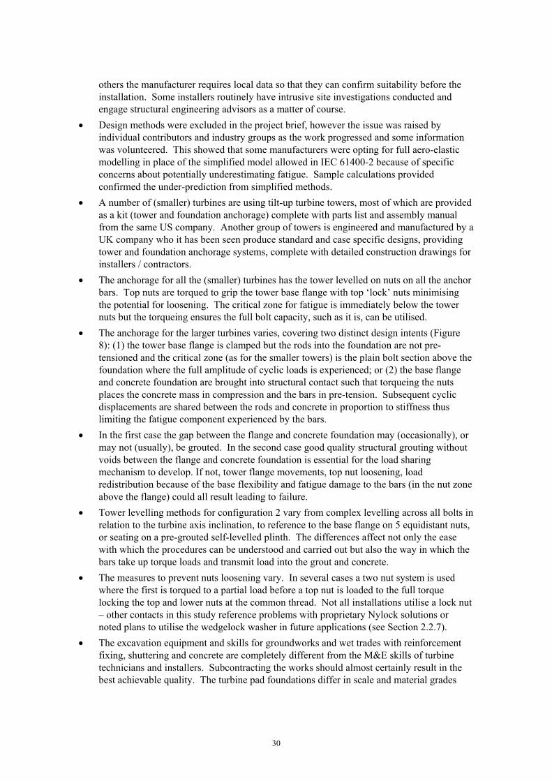
30
others the manufacturer requires local data so that they can confirm suitability before the installation. Some installers routinely have intrusive site investigations conducted and engage structural engineering advisors as a matter of course.
Design methods were excluded in the project brief, however the issue was raised by individual contributors and industry groups as the work progressed and some information was volunteered. This showed that some manufacturers were opting for full aero-elastic modelling in place of the simplified model allowed in IEC 61400-2 because of specific concerns about potentially underestimating fatigue. Sample calculations provided confirmed the under-prediction from simplified methods.
A number of (smaller) turbines are using tilt-up turbine towers, most of which are provided as a kit (tower and foundation anchorage) complete with parts list and assembly manual from the same US company. Another group of towers is engineered and manufactured by a UK company who it has been seen produce standard and case specific designs, providing tower and foundation anchorage systems, complete with detailed construction drawings for installers / contractors.
The anchorage for all the (smaller) turbines has the tower levelled on nuts on all the anchor bars. Top nuts are torqued to grip the tower base flange with top ‘lock’ nuts minimising the potential for loosening. The critical zone for fatigue is immediately below the tower nuts but the torqueing ensures the full bolt capacity, such as it is, can be utilised.
The anchorage for the larger turbines varies, covering two distinct design intents (Figure 8): (1) the tower base flange is clamped but the rods into the foundation are not pre-tensioned and the critical zone (as for the smaller towers) is the plain bolt section above the foundation where the full amplitude of cyclic loads is experienced; or (2) the base flange and concrete foundation are brought into structural contact such that torqueing the nuts places the concrete mass in compression and the bars in pre-tension. Subsequent cyclic displacements are shared between the rods and concrete in proportion to stiffness thus limiting the fatigue component experienced by the bars.
In the first case the gap between the flange and concrete foundation may (occasionally), or may not (usually), be grouted. In the second case good quality structural grouting without voids between the flange and concrete foundation is essential for the load sharing mechanism to develop. If not, tower flange movements, top nut loosening, load redistribution because of the base flexibility and fatigue damage to the bars (in the nut zone above the flange) could all result leading to failure.
Tower levelling methods for configuration 2 vary from complex levelling across all bolts in relation to the turbine axis inclination, to reference to the base flange on 5 equidistant nuts, or seating on a pre-grouted self-levelled plinth. The differences affect not only the ease with which the procedures can be understood and carried out but also the way in which the bars take up torque loads and transmit load into the grout and concrete.
The measures to prevent nuts loosening vary. In several cases a two nut system is used where the first is torqued to a partial load before a top nut is loaded to the full torque locking the top and lower nuts at the common thread. Not all installations utilise a lock nut – other contacts in this study reference problems with proprietary Nylock solutions or noted plans to utilise the wedgelock washer in future applications (see Section 2.2.7).
The excavation equipment and skills for groundworks and wet trades with reinforcement fixing, shuttering and concrete are completely different from the M&E skills of turbine technicians and installers. Subcontracting the works should almost certainly result in the best achievable quality. The turbine pad foundations differ in scale and material grades

31
(some specify higher grade mixes with sulphate resisting properties) but all are clearly specified and are readily obtainable by contractors with local suppliers.
In many cases the tower and associated anchorage (bolts, nuts, washers and template rings) are provided as a package to the installer (main contractor) by the tower manufacturer who in turn can supply the materials for the cage construction to the groundworks subcontractor. Where this is not done it would be a simple change to make and would remove any potential for inferior / unapproved materials to be substituted.
The strict adoption of the intended turbine tower bolted flange connection detail was illustrated by one case where extensive piling was required to deal with poor quality made-up ground at a particular site. Rather than engineer an efficient integration of a tower/pile solution, the piles supported the ‘standard’ pad foundation, embedded cage and bolted base flange solution. Retaining the ‘standard’ solution has some logic but could be argued to have missed the opportunity for a more efficient, cost-effective and inherently more resilient structural support detail. It does therefore demonstrate the strength of commitment to the standard product configuration.
The underbase flange grouting is potentially the most problematic activity. It is a wet trade which can only follow several weeks after the foundation works are complete and the base has cured. A good quality result requires a carefully controlled mix, placed in a timely manner with good formwork/seals inside and outside the flange, placed in such a way that air is not trapped and the grout surface does not settle below the underside of the flange. The congestion and high specification grout mean this is a difficult task which must be performed expertly as there will be limited external indicators if the workmanship is poor. The absence of voids is stipulated in one case but for the most part the specifications/ drawings are silent on the criticality and structural importance of the grouting operation. Considering that other designs also introduce grout in the same zone but for non-structural purposes, it must be assumed that installers may not fully appreciate the significance in individual cases, particularly when they install and maintain turbines of different designs for different manufacturers. It is notable that in one case a level grouted plinth is created on which to land the tower (rather than infill the under-flange gap once the tower is in place). This relies on the tower base being level and undistorted to fit in intimate contact with the plinth – however the issues with voids and poor quality construction can more readily be avoided.
Approaches to quality assurance and controls vary from reliance on MCS certification, to providing pass-worded access to latest drawings only through a manufacturer’s web portal, to requiring as-built confirmation and photographic evidence either in free format against a check list or by completing a detailed interactive report to the manufacturer’s template for different stages from project management and through the build. The last example requires satisfactory completion for the turbine ‘activation key’ to be released and includes questions requiring as-built details not simple check sheet confirmation. Furthermore evidence of materials supply tickets (concrete and grout) and photographs at key intermediate stages are required to ensure that inferior products or poor workmanship cannot go undetected. Although the sophisticated systems relate to the larger capacity / cost turbines, the strength of the assurance gained, together with the higher number of smaller turbines, suggests the approach is worthy of wider consideration.
Emerging SWT are tending to VAWT technologies. In these instances simplified design methods are not permitted in IEC 61400-2 which removes some aspects of concerns. Nevertheless those turbines in the early stages of development and prototype production covered in this study all demonstrated fresh thinking on the configuration of structural supports and foundations, introducing concepts like raked supports, screw pile foundations,

32
and the use of pre-cast units to minimise reliance on the quality of site work. There is insufficient evidence to opine on the viability of these alternatives but they underline the industry awareness of previous structural support / foundation problems and a commitment where possible to engineer out potential problems.

33
3 PRACTICE IMPLICATIONS AND RECOMMENDATIONS
The level of engagement with the project has varied between manufacturers but in principle the cooperation from individuals and trade bodies has been good. There is full recognition of past failures and a desire to see they cannot be repeated. Despite the focus of the project brief on construction and installation practices, representatives of the RenewableUK Small and Medium Wind Strategy Group felt in general the standards of workmanship and competence in the installer community were good. Concerns were expressed about the potential for design errors and the erosion of design conservatism by cumulative effects of marginal compliances which, coupled with an isolated site error, could mean failures related to multiple contributory causes. This study has therefore also included some consideration of load calculation methods and the understanding of the capacity and endurance of different design details. The recommendations therefore span design and construction issues.
Site specific design – improve recognition amongst manufacturers and installers that compared with the product certification of machinery for multiple applications, civil engineering almost always requires a bespoke approach reflecting local ground and environmental conditions. Site specific conditions (and re-locations, perhaps enforced by planners) may require intrusive investigation and local measurements to confirm conditions for the standard design are met. If direct responsibility is not to be taken by manufactures but delegated to installers, they should be equipped with adequate design information such as the assumed range of structural / base stiffness, tower sizes, component weight, forces, movements and fatigue spectra for a professional structural engineer to check and adapt or re-design the foundation and structural support configuration if required.
The perspective of installers, many of whom work with a range of turbines for different manufacturers should be considered when providing build instructions, particularly as ostensibly similar bolted tower support connections may be designed to transmit loads (particularly fatigue) in radically different ways (1. By torqueing nuts to clamp the flange and relying on unstressed bolt section below the flange levelling nuts to sustain fatigue, or 2. By torqueing bolts such that structural grout below flange and the concrete foundation is compressed, minimising the fatigue bolt loads).
The full complement of levelling nuts and cosmetic grouting that would be acceptable for Options 1 could leave bolts intended to work as in Option 2 with limited fatigue endurance under the applied loads. It is recommended that drawings and specifications put clear emphasis on the reasons and imperative for compliance so that ‘experience’ is not brought to bear inappropriately. There are other examples where again the specifications are already clear in fact but could be explained and emphasised more strongly e.g. nut numbers / combinations and locking mechanisms, structural grouting standards etc).
It appears that MCS accreditation coupled with manufacturer specific training and authorisation are effective barriers to entry for the vast majority of the market, at least while Government subsidies are needed for adoption of the technologies to be viable. At present, product and installer certifications do not extend to project certification although the importance of site specific considerations is noted above. A proportionate complement to existing MCS controls would be for manufacturers to disseminate the good assurance practices whereby data and photographic evidence, particularly related to critical materials (concrete, grout) and temporary conditions (pre-pour) are recorded.

34
Although limitations of previous design practices (IEC 61400-2, simplified method) have been recognised and certification strengthened to make the structure and support mandatory elements, the legacy for existing installations and transition period to 2017/19 mean there is ongoing uncertainty and potential for confusion. The issues vary by manufacturer / turbine / model general etc and renewed attention may best be driven by HSE through RenewableUK who are already engaged with the issues. This study has highlighted a range of potential sources for existing structures to have less fatigue resistance than was intended or would be designed for in future. The extent to which this may leave some structures vulnerable to failure at the structural supports within the design life is unclear. However, it would be prudent for manufacturers to prioritise checks on existing installations where people may frequently be in close proximity.

35
APPENDIX A – EXTRACTS FROM REFERENCE STANDARDS RELATED TO SMALL WIND TURBINE STRUCTURAL SUPPORTS AND FOUNDATIONS
IEC 61400-2 Editions 2.0 (2006) and 3.0 (2013)
This section reproduces key elements of the small wind turbine (SWT) standard relevant to the design of structural supports and foundations as addressed in this study. Edition 2 which would have been used for recent installations forms the main reference in the table below. The right hand column highlights key changes and additions in Edition 3, by implication addressing weaknesses identified from experience in applying Edition 2. Although Edition 3 constitutes the ‘current’ standard, Edition 2 applied when the SWT known to have encountered foundation problems were designed and, furthermore, it remains relevant in light of the transition arrangements discussed in Section 2.2.4 of the main report, through to 2017 or 2019.
The table, does not cover every area and it should not be applied directly. Its purpose here is to highlight the main aspects covered, key areas of improvement and potential for weaknesses in earlier design.
Where the same provision appears in both standards and is useful to consider in understanding the coverage the content is reproduced spanning both columns. Where the content is added to in Edition 3 the common provision is presented in the Edition 2 column with the additions only in the Edition 3 column.
The final Annexes are new in Edition 3, without comparison in Edition 2.
The change in clause numbering is due to re-ordering to separate design and testing aspects in Edition 3. In most aspects the content is identical.

36
Table 3 Key provisions of SWT standard IEC 61400-2 Edition 2.0 and changes / additions introduced in Edition 3.0
Cl. IEC 61400-2 Edition 2.0 IEC 61400-2 Edition 3.0 Cl. Comment
1 Scope. This part of IEC 61400 deals with safety philosophy, quality assurance, and engineering integrity and specifies requirements for the safety of small wind turbines (SWTs) including design, installation, maintenance and operation under specified external conditions. Its purpose is to provide the appropriate level of protection against damage from hazards from these systems during their planned lifetime. This standard is concerned with all subsystems of SWTs such as ….., support structures, foundations……….
1 Scope explicitly covers support structures and foundations
4 Symbols and abbreviated terms 4
Addition: definition of the system of axes for VAWT Addition reflects increasing development / use of VAWT systems in addition to HAWT
5 Principal Elements 5
5.2 Design methods …… The design method for turbines covered under this standard is depicted in Figure .. A simplified approach is permitted for a variety of turbine configurations.
5.2
Fig 2 Additional steps: - Resonance analysis, limit state analysis and critical
deflection - Support structure part of turbine system & sample
foundation systems shall be provided - Evaluation of turbine dynamics - Documentation and WT markings
Fig 3 New explicit emphasis on resonance analysis, provision of sample foundation and support structure, evaluation of dynamics and thorough documentation.
5.2 Primary turbine data are measured in a “design data test” (see 9.2), after which values of predicted design loads shall be obtained in one or a combination of the following three ways:
The design loads shall be obtained in one or a combination of the following three ways. The design loads shall be verified by measured “design data test” (See 13.2): It is recommended that in-house tests for design data are conducted early in the development.
5.2 Additional emphasis on timely verification of design loads (including in simplified loads and simulation model approaches). Referenced clauses on tests to verify design data are unchanged.
… simplified calculation method 1. Simplified loads methodology Descriptive terms for first two of the three design methods subtly changed. Description of approaches more precise.
For certain turbine configurations a simplified calculation method is given. A limited set of load cases and configurations is given in 7.4 with simple formulas and simplified external conditions.
Use of a structural dynamics model in combination with design data testing and limited full-scale load measurements to verify the model.
2. Simulation model
This approach uses a structural dynamics simulation model in combination with wind turbine and application adequate assumptions.
Full scale load measurement with load extrapolation 3. Full scale load measurement with load extrapolation

37
Cl. IEC 61400-2 Edition 2.0 IEC 61400-2 Edition 3.0 Cl. Comment
6/6.2 6 External Conditions/ 6.2 SWT classes. The external conditions to be considered in design are dependent on the intended site or site type for a SWT installation. SWT classes are defined in terms of wind speed and turbulence parameters. The values of wind speed and turbulence parameters are intended to represent the characteristic values of many different sites and do not give a precise representation of any specific site. The goal is to achieve SWT classification with clearly varying robustness governed by the wind. Table 1 specifies the basic parameters, which define the SWT classes
6/6.2
Addition: The intention of the classes is to cover most applications, and reference should be made to Annex L [new] for other wind conditions that may be experienced.
Stronger direction that standard wind classes may not apply – See also Annex L coverage and attention to the role of turbulence
In cases where a special design (for example special wind conditions, * or other external conditions or a special safety class) is necessary, a further SWT class, class S, is defined. The design values for the SWT class S shall be chosen by the designer and specified in the design documentation. For such special designs, the values chosen for the design conditions shall reflect a more severe environment than anticipated for the use of the SWT.
Insertion: * or other wind conditions (per Annex L)
Table 1 – basic parameters for SWT classes Addition: in relation to the turbulence intensity function …noting that Annex M [new] discusses observations regarding turbulence intensity
7 7 Structural design 7
7.1 General Wind turbine system structural design shall be based on verification of the structural integrity of the components in the critical load paths from the rotor blades to the foundation. The ultimate and fatigue strength of all structural members * shall be verified by calculations or tests, or a combination of both, to determine the structural integrity of a SWT with the appropriate safety level.
Insertion:….* (for example: rotor blade, rotor hub, rotor shaft, nacelle, yaw shaft, tower, connections)… Addition: The scope of verification is the same regardless of the design methodology chosen (7.2).
7.1 Clarification
7.2 Design methodology 7.2

38
Cl. IEC 61400-2 Edition 2.0 IEC 61400-2 Edition 3.0 Cl. Comment
- simplified load equations; - aeroelastic modelling; - mechanical loads testing
1) simplified loads methodology; 2) simulation model; 3) full scale load measurement.
Renamed design methods
7.3/7.3.1 Loads and load cases / Vibration, inertial and gravitational loads 7.3/7.3.2
Attention should be paid to excitation of the natural frequencies of the turbine system.
A resonance analysis, such as provided by a Campbell diagram, shall be provided for the main structural components of the wind turbine system (see [new] Annex I).
Requirement for more rigorous attention to potential for resonance
7.4 Simplified load model For certain turbine configurations the loads can be derived using simple, conservative equations for a limited set of load cases. Annex F provides background information for these equations. If the turbine configuration does not meet those configuration requirements the simplified loads methodology cannot be used, instead the alternative (aeroelastic) / simulation modelling (7.5) or load measurements shall be used (7.6).
7.4 Continued allowance for simplified method
The turbine configurations that are able to use the simplified loads methodology shall meet all of the following requirements: • horizontal axis; • 2 or more bladed propeller-type rotor; • cantilever blades; and • rigid hub (not teetering or hinged hub).
Addition: • coordinated blade movement (not independent and uncoordinated pitching, coning, etc.);
Recognition that simplified method is not suitable if blade movements are independent
7.4.5 Load case D: maximum thrust 7.4.5
The SWT can be exposed to high thrust loads on the rotor. The thrust load acts parallel to the rotor shaft and has a maximum value given by: Fx−shaft = CT0,5ρ(2,5×Vave )2 πR2 (32) where CT is the thrust coefficient, equal to 0,5.
Additions: NOTE See Clause F.3. However, caution should be exercised with wind turbines that operate at high rotational speeds at 2,5 Vave, where a CT of 8/9 may be more appropriate.
Reference to caution that empirical equation parameters may not apply for turbines operating at high rotational speeds.
9 Testing 13
9.2.3 Maximum yaw rate 13.2.3
Addition: definitions for different turbine yaw types Reflecting new developments

39
Cl. IEC 61400-2 Edition 2.0 IEC 61400-2 Edition 3.0 Cl. Comment
9.4 Duration testing The purpose of the duration test is to investigate: • structural integrity and material degradation (corrosion, cracks, deformations); • quality of environmental protection of the wind turbine; and • the dynamic behaviour of the turbine. During the duration test, test procedures shall be implemented to determine if and when the test turbine successfully meets the following test criteria. The wind turbine will have passed the duration test when it has achieved:
13.4
- reliable operation during the test period; - at least 6 months of operation; - at least 2 500 h of power production in winds of any velocity; - at least 250 h of power production in winds of 1,2 Vave and above; - at least 25 h of power production in winds of 1,8 Vave and above; and.
Addition: - at least 10 min in winds of 2,2 Vave and above but not less than 15,0 m/s during which the turbine shall be in normal operation
Additional test criterion for operation in higher winds
It is common for small turbine manufacturers to offer the same turbine on a variety of tower configurations. In this situation, a duration test is not required for each tower if it can be adequately demonstrated by calculation and short-term testing that the dynamic and static behaviours of an alternate tower do not lead to the exceeding of the design limits of the system.
Deleted from Edition 3.0 Testing now needs to be performed for different tower configurations even for the same turbine types
Addition Reporting of duration test The duration test report shall contain the following information: …. Itemised listing
13.4.4 Clarification stipulating many aspects to be covered in duration test report.
11/11.1 Support structure / General The support structure is a critical component for the SWT. The support structure carries the loads from the turbine. If the rotor swept area is > 2 m2 then the support structure shall be included as part of the SWT system
10/10.1
Insertion: and designed as described in Clause 7. Clarification
Support structures shall also meet local codes and regulations.
Deleted from Edition 3.0 Assumed edited out only as superfluous.
11.2 Dynamic requirements 10.2

40
Cl. IEC 61400-2 Edition 2.0 IEC 61400-2 Edition 3.0 Cl. Comment
SWT support structure resonances can be a critical design issue and as such consideration should be taken to avoid continuous operation at turbine system resonance frequencies leading to excessive vibrations. This is particularly important if the support structure is an occupied building.
An evaluation of the wind turbine system dynamics shall be conducted. By experimentation and/or analysis it shall be shown to be generally free of damaging dynamic or resonant conditions that can affect the structure and/or cause loss of control functions. For further information see Annex I. [new]
Strengthened requirement for explicit assessment of dynamics and resonance.
11.5 Foundations … the manufacturer shall provide detailed drawings of a sample foundation system and the appropriate soil conditions as applicable, as well as design loads for the foundation.
…. the manufacturer shall design a sample foundation system for normal soil conditions and design loads.
10.5 More explicit requirement for sample foundation design.
12 Documentation requirements 11
Addition: Product manuals / Specification Detailed listing including s) SWT class…. z) available support structures..
11.2 /11.2.2
Clarification stipulating many aspects to be covered in manuals
12.2 12.2.1
Installation / General The manufacturer of SWTs shall provide drawings, procedures, specifications, instructions and packing lists for assembly, installation, operation and erection of the SWT.
11.2.3 11.2.3.1
12.2.2 Support structure ……This shall include but is not limited to: • details on the mechanical turbine/tower connection; • details on the electrical turbine/tower connection; • minimum blade/tower clearance; • maximum allowable tower top deflection; and • maximum tower top loads (stating whether a safety factor has been included, and its magnitude);
Addition: • a sample support structure design.
11.2.3.2 Reflects strengthened requirement for sample design
For turbines with a swept area of more than 2 m2, it is recommended that the above information be supplied. For these turbines the information required by 11.5 shall be provided.
Addition: ….required by 10.5 shall be provided including drawings of a sample foundation stating assumed soil conditions, operating loads, and access loads.
Clarification

41

42
Cl. IEC 61400-2 Edition 2.0 IEC 61400-2 Edition 3.0 Cl. Comment
Annex F Development of the simplified loads methodology Annex F
Addition: Caution regarding use of simplified equations The simplified design equations were developed in previous editions and validated against the then available measurements. Subsequently there have been concerns expressed regarding a number of load cases: • The treatment of fatigue in load case A (in this annex) may not be sufficiently conservative. Ordinarily such a lack of conservatism would be masked by the static load cases especially when used with the full safety factors. Therefore care should be taken if reducing safety factors in the static load cases as this could cause fatigue to become an issue. See further explanation in load case A in Clause F.4 below. • The treatment of maximum thrust in load case D (in this annex) may not be sufficiently conservative if the rotational speed of the turbine at 2,5 Vave is high. If this is the case then an increased value of CT should be used as noted in load case D Clause F.4 below.
F.3 Caution over use of simplified method The observation on the static load case dominating in turn needs some caution as the degree to which this is true depends on the relative fatigue/strength properties of the component being designed (i.e. for components with a poor inherent fatigue detail the condition may be particularly critical).
F.2 General General relationships F.4
A Loadcase A: normal operation A
Addition: CAUTION: The treatment of fatigue in the simplified equations generally predicts very small fatigue loads. The number of fatigue cycles used in the simplified equations is the number of times the blade passes the tower in the design lifetime (which is an artificially large number) which may compensate for these low loads. However, the predicted fatigue loads are so small that a designer might conclude that all fatigue cycles will be below the fatigue limit and therefore may neglect fatigue altogether. This would be unwise as a comparison with aeroelastic models reveals. The interplay of the number of cycles and the loads varies with the size of the turbine, and as an example for one turbine the under-prediction by the simplified equations is a factor of 2,4 for the tower top thrust, and 7,7 for the shaft bending moment. The reason for the under-prediction of the shaft bending appears to relate at least in part to the omission of gyroscopic loads due to yawing from the fatigue case in the simplified equations. Plainly the discrepancies for these examples are significant and indicate real potential for a turbine and tower to be under-designed. For this reason care should be taken if reducing safety factors in the static load cases as this could cause fatigue to become an issue.
Caution that reduced safety factors may lead to fatigue conditions dominating in reality but not being revealed from simplified equations.

43
Cl. IEC 61400-2 Edition 2.0 IEC 61400-2 Edition 3.0 Cl. Comment
D Loadcase D: Maximum thrust D
Addition: However, caution should be exercised with wind turbines that operate at high rotational speeds at 2,5 Vave, where a CT of 8/9 may be more appropriate.
Caution that empirical thrust equation derived for low rotational speeds may be unrealistic if applied to higher rotational speeds.
H Loadcase H: survival wind Loadcase H: extreme wind loading H
Addition: The wind speed Ve50 is commonly referred to as “survival” wind speed but is more precisely referred to as the extreme wind speed (3-s gust with a recurrence period of 50 years) per definition 3.19. CAUTION: Care should be taken in using Equation (42) (i.e. Equation (F.42)). This is because Fx is proportional to (tip speed ratio)^2 and so if the rotor speed is controlled to a low value then the equation predicts a thrust force that can approach zero. This can be far lower than that suggested by the thrust in the parked rotor case (Equation (41), i.e. Equation (F.34)), which is obviously wrong. Therefore if the spinning rotor is controlled to a very low speed then the higher thrust given by Equation (41) (i.e. Equation (F.34)) shall be used instead of the lower thrust given by Equation (42) (i.e. F.42).
Caution: error in extrapolating design loads to low rotational speeds in extreme winds.
Addition: Annex I (normative) Natural frequency analysis The main natural frequencies of the wind turbine shall be evaluated by means of a resonance diagram (e.g. Campbell diagram). It shall contain the natural frequencies (f_N) and the relevant excitation frequencies (f_E) of the wind turbine. At least the natural frequencies of the main structural components of the wind turbine shall be considered. These are the natural frequencies of the: tower or support structure; rotor blades; and, depending on the design: drive train; bracing between rotor blades and hub (e.g. stiffeners) and bracing of tower (e.g. guyed tower or other support structure)…………. …….a control function that decouples the relationship between wind speed and rotor speed (for example a rotor overspeed control that maintains a constant speed) can lead to damaging resonance.
I Addition of requirement for natural frequency analysis

44
Cl. IEC 61400-2 Edition 2.0 IEC 61400-2 Edition 3.0 Cl. Comment
Addition: Annex L (informative) Other wind conditions The purpose of this annex is to illustrate that other inflow conditions exist which are not covered elsewhere in the standard, and which can have significant detrimental effects on the longevity, safety, function and performance of SWTs. The four standard SWT classes, wind conditions and load cases defined earlier in this standard are intended to be representative for typical wind turbine environments, similar to where large wind turbines are installed, with a relatively unobstructed air flow. As stated in 6.3 these are termed standard wind conditions (SWC). However, SWTs are in some cases installed in environments where other wind conditions (OWC) exist. Therefore the standard wind conditions model is no longer valid for use by the designer without modification. Sometimes these other wind conditions are simple in nature, and sometimes they are complex in nature. This annex is organised to treat each aspect in isolation. L.2 Typical situations L.3 Directionally dependent flow L.4 Inclined flow L.5 Turbulence L.7 Gust factors
L Recognition of limitation of standard wind conditions and provision to account for circumstances where turbines are to be located in ‘other’ wind situations. Factors that affect wind flow and means to account for them are addressed.

45
IEC 61400-22 (2010)
Although not explicitly embraced by the MCS/RUK certification schemes for SWT in the UK, this section examines the approach in the IEC conformity testing and certification standard as it applies to structures and foundations advocated. IEC 61400-22 itself repeatedly makes reference back to the relevant standards IEC 61400-1, IEC 61400-2 or IEC 61400-3 as appropriate, implying the potential for adopting IEC61400-22 for SWT (e.g. Clause 7.2).
The prototype and type certificates in IEC 61400-22 relate most closely to the product certification stages in the UK. However although foundation design requirements are evaluated (Clause 8.3.10) (covering loads - static, dynamic and fatigue – and range for allowable rotations/flexibility), the evaluation of the foundation design is an optional module (Clause 8.6) in the type certification. If it is included, the certification body requires that reinforcement, concrete layout and construction sequence plans be included in the foundation design documentation. These plans shall be in sufficient detail to allow the certification body to verify the adequacy of the foundation design, taking into account the specified construction processes.
The purpose of project certification (Clause 7.3) is to evaluate whether type-certified wind turbines and particular support structure / foundation(s) designs are in conformity with the external conditions, applicable construction and electrical codes and other requirements relevant to a specific site. The process requires the certification body to evaluate whether the wind conditions….. and soil properties at the site conform with those defined in the design documentation….[on which type certification is based]. Clause 7.3 also states that the evaluation includes safety and quality. Required modules for project certification include – site conditions evaluation, integrated load analysis, support structure design evaluation, manufacturing surveillance etc.
The site conditions evaluation (Clause 9.2) examines whether parameters including soil properties conform to those in the design documentation.
The purpose of the integrated load analysis (Clause 9.4) is to examine whether the site-specific loads and load effects on the integrated wind turbine structure, including the rotor-nacelle assembly plus the support structure and supporting soils, are derived in conformity with the design basis. No analysis is needed if the conditions are more benign than those assumed in the type certification (Clause 9.4.2). If analysis is necessary it is stipulated that this must take due account of the complete structural dynamics.
The site specific support structure design evaluation (Clause 9.6) is required to at least include (Clause 9.6.2):
evaluation of the design of the support structure with respect to the results of the integrated load analysis;
calculated support structure stiffness and damping as compared to the assumptions made in the load calculations’ evaluation of the geotechnical design documentation based on the design basis;
evaluation of the design documentation for the support structure;
evaluation of the manufacturing plan, transportation plan, installation plan and maintenance plan however only with respect to the structural integrity of the final installed (permanent) support structure; and

46
evaluation of proposed corrosion protection systems again design premises specified in the design basis.
Support structure manufacturing surveillance (Clause 9.9) carried out under project certification includes inspection / audit activities to verify that the manufacture of support structure(s) for the specific project is carried out according to the approved design and with the intended quality. The surveillance extends to the manufacture of the primary load-carrying steel structure and build of concrete structures. The detailed extent (Clause 9.9.2) is tailored by the certification body reflecting things like experience, quality control procedures in place etc.
Although the project certification requirements are comprehensive, for an SWT being installed in wind conditions within its certified class, where ground conditions correspond to those in the sample design, and installed by an experienced installer with thorough drawings and specifications from the manufacturer, little beyond the extant product certification may be required.
What the approach does highlight, however, is the appropriate rigor and re-evaluation if the site conditions differ from the product design assumptions. In turn this highlights the importance of clear and comprehensive design / product documents so that site compliance can be assured with confidence.

47
REFERENCES
1 Renewable UK. ‘Small and Medium Wind Strategy Report 2014’, RenewableUK, November 2014.
2 MMI Engineering Ltd, ‘Study and development of a methodology for the estimation of the risk and harm to persons from wind turbines’, HSE Research Report RR968, 2013.
3 Goodwin, P. ‘Safety fears after faults found in toppled turbines’, Western Morning News, 8 September 2014. http://www.westernmorningnews.co.uk/Safety-fears-faults-toppled-turbines/story-22887067-detail/story.html#quC5cfqbsc7YphTD.99
4 Renewable UK. ‘Letter to the Secretary of State for Energy and Climate Change – Benefits of small and medium wind in the UK’, 28 July 2015. http://www.renewableuk.com/download.cfm?docid=378CA232-4522-4EE4-8735682154A838AE
5 Lawson, J. ‘More than just a pretty face?, VAWT Feature in Real Power, Issue 41, Summer 2015 (available from www.renewableuk.com)
6 United Nations. ‘Framework Convention on Climate Change- Kyoto protocol’, http://unfccc.int/kyoto_protocol/items/2830.php
7 Gsanger, S and Pittelourd, J. ‘Small Wind World Report 2014’, World Wind Energy Association, March 2014 (www.wwindea.org).
8 ‘Green energy subsidies facing the axe’, 19 July 2015, http://www.telegraph.co.uk/finance/personalfinance/energy-bills/11748958/Green-energy-subsidies-facing-the-axe.html
9 Ofgem e-serve. ‘Feed-in Tariff Generation & Export Payment Rate Table for Non-Photovoltaic Installations, updated for FIT Year 6 (1 April 2015 to 31 March 2016)’.
10 RenewableUK. ‘Small and medium wind UK market report’, March 2015.
11 International Electrotechnical Commission. ‘Wind Turbines – Part 2: Small wind turbines’, IEC 61400-2, Edition 3.0, 2013-12. ISBN 978-2-8322-1284-4.
12 International Electrotechnical Commission. ‘Wind Turbines – Part 22: Conformity testing and certification’, IEC 61400-22, Edition 1.0, 2010-05. ISBN 978-2-88910-943-2
13 BS EN 61400-2:2006, ‘Wind turbines – Part 2: Design requirements for small wind turbines’, July 2006
14 ISO 2394 ‘General principles on reliability for structures’, 1998
15 HSE. ‘Technical review of ISO 2394 General principles on reliabilities for structures’, Offshore Technology Report prepared by MSL Engineering, OTO 1999 074, 1999.
16 BWEA. ‘Small wind turbine performance and safety standard’, 1st edition, 29 February 2008. [BWEA is now RenewableUK]

48
17 Microgeneration Certification Scheme. ‘History of the microgeneration certification scheme’,http://www.microgenerationcertification.org/images/MCS%20History%202013%20FINAL%201.0.pdf.
18 Ofgem.ROO-FIT. https://www.ofgem.gov.uk/environmental-programmes/feed-tariff-fit-scheme/applying-feed-tariff/roo-fit
19 MCS. ‘Requirements for MCS contractors undertaking the supply, design, installation, set to work commissioning and handover of micro and small wind turbine systems’, MIS 3003, Issue 3.4, May 2015.
20 MCS. ‘Product certification scheme requirements: small wind turbines’, MSC 006, Issue 2.1, 15 January 2014.
21 Renewable UK. ‘Small wind turbine safety standard’, 15 January 2014.
22 DNV-GL. ‘Type and component certification of wind turbines according to IEC 61400-22 (DNVGL-SE-0074) and Project certification of wind farms according to IEC 61400-22 (DNVGL-SE-0073)’, December 2014.
23 Renewable Energy Consumer Code. https://www.recc.org.uk/
24 RenewableUK. ‘Small Wind Safety Guidelines”, Unpublished Draft/Work in Progress, received March 2015.
25 TUV SUD NEL Ltd. ‘A feasibility study of the scope for revising the simplified load model in IEC 61400-2:2006’, Report for the National Measurement Office (under a contract to BIS as part of the National Measurement System’s Engineering & Flow Programme), TUV NEL Report No. 2012/211, June 2012.
26 Trahair, N S et al. ‘The behaviour and design of steel structures to EC3’, 4th Edition, Taylor & Francis, ISBN 0-203-93593-4, 2008.
27 Building Research Establishment. ‘Design of structural connections to Eurocode 3, Frequently asked questions’, ISBN 80-01-02838-0, 2003.
28 BCSA/SCI ‘Joints in steel construction: Moment-Resisting Joints to Eurocode 3’, ISBN: 978-1-85-942209-0, 2013.
29 David Allen Agri Business, Technical/Expert witness support enquiry, June 2015.
30 European Steel Design Education Project (ESDEP), Lecture 12.6: Fatigue Behaviour of Bolted Connections. http://www.fgg.uni-lj.si/~/pmoze/ESDEP/master/wg12/l0600.htm
31 Kaczinski, M R et al. ‘Fatigue resistant design of cantilevered signal, sign and light supports’, National Research Council, National Academy Press, 1998.
32 Bolt Science Ltd. ‘The use of two nuts to prevent self loosening’. www.boltscience.com, accessed 2015.
33 Nord-Lock. ‘Wedgelock washers’ http://www.nord-lock.com/nord-lock/wedge-locking/
34 Abacus Lighting. ‘Foundation design guidance; http://www.abacuslighting.com/pdf/foundations-high-mast.pdf

49
35 Frank, K. H. (1980). ‘Fatigue strength of anchor bolts’. Journal of the Structural Division, ASCE, 106(6), 1279-1293.
36 Richards, J H ‘Turn of the nut tightening of anchor bolts’, MSc Thesis, Texas A&M University, 2004.
37 McCalls Special Products. ‘The foundation anchor solution for wind turbines – The Macalloy Bar’. Available from www.macalloy.com, September 2012.
38 Boltight Ltd. ‘Foundation bolt tensioners for wind turbines’. Data Sheet DS-9, http://www.boltight.com/resources/Data-Sheets/DS-9-Foundation-Bolt-Tensioners.pdf
39 Miceli, F. ‘Wind farm constructions’ website by Vestas civil engineer, Francesco Miceli. http://www.windfarmbop.com/category/foundations/
40 Micelli, F. Personal communication, September 2015.

Published by the Health and Safety Executive 06/16

Review of small wind turbine construction instructions and specifically for structural supports and foundations
Health and Safety Executive
RR1081
www.hse.gov.uk
This research investigated the possible role of weaknesses in small wind turbine construction instructions in the potential for structural collapse associated with the structural supports and foundations. Build instructions relating to nine turbines of differing scale and design were obtained with industry cooperation. Analysis showed that although the stipulations were generally clear, the overall design intent of the details and criticality of certain aspects were not conveyed. As ostensibly similar details can be made to function intentionally in radically different ways, it is concluded that deviations from the required procedure could be better guarded against if the design intent and criticality were made explicit in each case. This would particularly benefit installers working across a range of products from different manufacturers. Site practices could also be improved to achieve the required bolt tensions and structural grout integrity with greater surety.
Some good practices in assurance processes for the siting checks, engineering assessments and construction were seen including photographs and records of as-built details. Wider adoption should be encouraged to improve confidence in integrity.
Factors potentially contributing individually or in combination to failures were identified in a number of areas. Known concerns about the potential under-prediction of fatigue design loads using the simplified design method in the small wind turbine standard (IEC 61400-2) were underlined. Given the transition period to 2017/19 until more stringent controls apply to new and ongoing certifications, coupled with issueson the prior exclusion of the tower and foundation from the scope of certification in the UK, industry groups such as RenewableUK’s Small and Medium Wind Strategy Group who made a positive contribution to this study, are called on to renew their efforts encouraging manufacturers to proactively review the adequacy of existing and future certified installations.
This report and the work it describes were funded by the Health and Safety Executive (HSE). Its contents, including any opinions and/or conclusions expressed, are those of the authors alone and do not necessarily reflect HSE policy.