Embed Size (px)
Citation preview
RV-10 Wire HarnessInstallation Guide
Get wired and get fl ying.
Rev 10.26.06 A
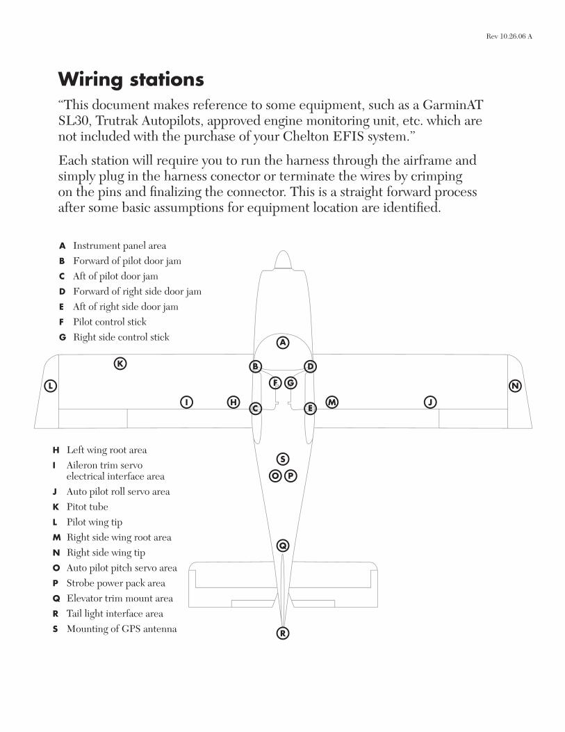
Wiring stations“This document makes reference to some equipment, such as a GarminAT SL30, Trutrak Autopilots, approved engine monitoring unit, etc. which are not included with the purchase of your Chelton EFIS system.”
Each station will require you to run the harness through the airframe and simply plug in the harness conector or terminate the wires by crimping on the pins and fi nalizing the connector. This is a straight forward process after some basic assumptions for equipment location are identifi ed.
A Instrument panel areaB Forward of pilot door jamC Aft of pilot door jamD Forward of right side door jamE Aft of right side door jamF Pilot control stickG Right side control stick
NL
A
B
HC
F G
D
EI J
K
M
O P
Q
R
SH Left wing root areaI Aileron trim servo
electrical interface areaJ Auto pilot roll servo areaK Pitot tubeL Pilot wing tipM Right side wing root areaN Right side wing tipO Auto pilot pitch servo areaP Strobe power pack areaQ Elevator trim mount areaR Tail light interface areaS Mounting of GPS antenna
Rev 10.26.06 A

Wiring assumptionsThese custom electrical harnesses are specifi cally designed with the following basic assumptions. It is assumed that the builder will be mounting the various pieces of equipment in the specifi ed locations.
Station A assumptionIt is assumed the following Aircraft components will be mounted in the vicinity of station A:• All associated and specifi ed Aircraft Circuit breakers• All associated and specifi ed electrical Master switches• Appropriate Ground Bus• Pinpoint GADAHRS/ADAHRS• GADAHRS/ADAHRS Alignment Ground/Quick Slave Switch• FreeFlight GPS WAAS Reciever (optional)• PFD Keyboard• MFD Keyboard• Aileron Trim Relay Deck• Elevator Trim Relay Deck• Elevator Trim Position sensor
Station B assumptionIt is assumed the following Aircraft components will be mounted in the vicinity of station B:• Microswitch for Pilot Door Ajar Annunciator
Station C assumptionIt is assumed the following Aircraft components will be mounted in the vicinity of station C:• Microswitch for Pilot Door Ajar Annunciator
Station D assumptionIt is assumed the following Aircraft components will be mounted in the vicinity of station D:
• Microswitch for Right side Door Ajar Annunciator
Station E assumptionIt is assumed the following Aircraft components will be mounted in the vicinity of station E:
• Microswitch for Right side Door Ajar Annunciator
Station F assumptionIt is assumed the following Aircraft components will be mounted in the vicinity of station F:• EFIS Mute Switch• Auto Pilot CWS Switch
Station G assumptionIt is assumed the following Aircraft components will be mounted in the vicinity of station G:• EFIS Mute Switch• Auto Pilot CWS Switch
Station H assumptionIt is assumed the following Aircraft components will be mounted in the vicinity of station H:• Left Wing Dissconnect Plug
Station I assumptionIt is assumed the following Aircraft components will be mounted in the vicinity of station I:
• Aileron Trim Servo Motor
Continued...
Rev 10.26.06 A
Wiring assumptions Continued
These custom electrical harnesses are specifi cally designed with the following basic assumptions. It is assumed that the builder will be mounting the various pieces of equipment in the specifi ed locations.
Station J assumptionIt is assumed the following Aircraft components will be mounted in the vicinity of station J:• Auto Pilot Roll Servo
Station K assumptionIt is assumed the following Aircraft components will be mounted in the vicinity of station K:• Pitot Heat Tube (We do have provisions to bring the
Pitot Tube wiring inboard if you the builder decide to mount the Pitot Tube there as opposed to outboard)
Station L assumptions:It is assumed the following Aircraft components will be mounted in the vicinity of station L:• Left Wing Strobe Light• Left Wing Navigation Light• MSU & OAT• Left Wing Landing Light (if high intensity discharge lights are used the ballast
must be mounted in this vicinity)
Station M assumptions:It is assumed the following Aircraft components will be mounted in the vicinity of station M:• Right Wing Dissconnect Plug
Station N assumptions:It is assumed the following Aircraft components will be mounted in the vicinity of station N:• Right Wing Strobe Light• Right Wing Navigation Light• Right Wing Landing Light (if high intensity discharge lights are used the ballast
must be mounted in this vicinity)
Station O assumptionIt is assumed the following Aircraft components will be mounted in the vicinity of station O:• Auto Pilot Pitch Servo
Station P assumptions:It is assumed the following Aircraft components will be mounted in the vicinity of station P:• Strobe Power Pack
Station Q assumptions:It is assumed the following Aircraft components will be mounted in the vicinity of station Q:• Elevator Trim Servo Motor
Station R assumptions:It is assumed the following Aircraft components will be mounted in the vicinity of station R:• Tail Navigation Light• Tail Strobe light
Rev 10.26.06 A
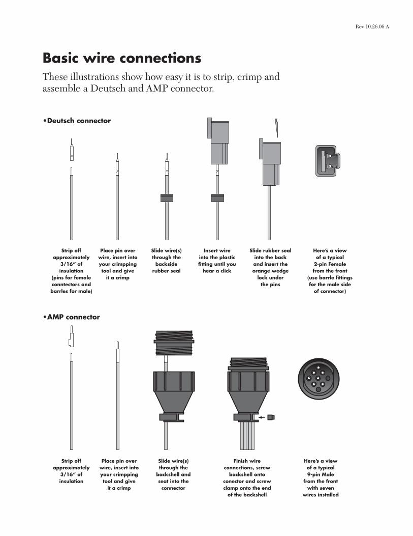
Basic wire connectionsThese illustrations show how easy it is to strip, crimp and assemble a Deutsch and AMP connector.
Strip off approximately
3/16” ofinsulation
(pins for female conntectors and barrles for male)
Place pin over wire, insert into your crimpping tool and give
it a crimp
Slide wire(s) through the
backside rubber seal
Insert wire into the plastic fi tting until you
hear a click
Slide rubber seal into the back and insert the orange wedge
lock under the pins
Here’s a view of a typical
2-pin Female from the front
(use barrle fi ttings for the male side
of connector)
•Deutsch connector
•AMP connector
Strip off approximately
3/16” ofinsulation
Place pin over wire, insert into your crimpping tool and give
it a crimp
Slide wire(s) through the
backshell and seat into the
connector
Finish wire connections, screw
backshell onto conector and screw clamp onto the end
of the backshell
Here’s a view of a typical 9-pin Male
from the front with seven
wires installed
Rev 10.26.06 A
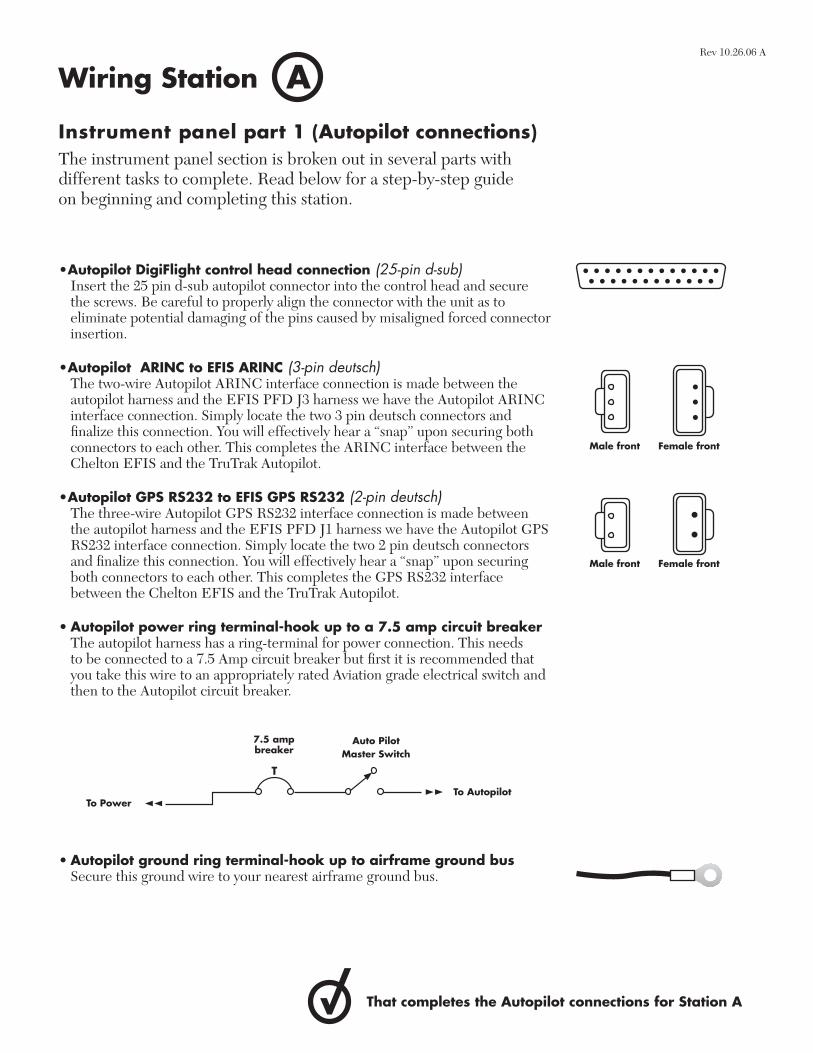
Instrument panel part 1 (Autopilot connections)The instrument panel section is broken out in several parts with different tasks to complete. Read below for a step-by-step guide on beginning and completing this station.
•Autopilot DigiFlight control head connection (25-pin d-sub) Insert the 25 pin d-sub autopilot connector into the control head and secure
the screws. Be careful to properly align the connector with the unit as to eliminate potential damaging of the pins caused by misaligned forced connector insertion.
•Autopilot ARINC to EFIS ARINC (3-pin deutsch)The two-wire Autopilot ARINC interface connection is made between the autopilot harness and the EFIS PFD J3 harness we have the Autopilot ARINC interface connection. Simply locate the two 3 pin deutsch connectors and fi nalize this connection. You will effectively hear a “snap” upon securing both connectors to each other. This completes the ARINC interface between the Chelton EFIS and the TruTrak Autopilot.
•Autopilot GPS RS232 to EFIS GPS RS232 (2-pin deutsch)The three-wire Autopilot GPS RS232 interface connection is made between the autopilot harness and the EFIS PFD J1 harness we have the Autopilot GPS RS232 interface connection. Simply locate the two 2 pin deutsch connectors and fi nalize this connection. You will effectively hear a “snap” upon securing both connectors to each other. This completes the GPS RS232 interface between the Chelton EFIS and the TruTrak Autopilot.
• Autopilot power ring terminal-hook up to a 7.5 amp circuit breaker The autopilot harness has a ring-terminal for power connection. This needs
to be connected to a 7.5 Amp circuit breaker but fi rst it is recommended that you take this wire to an appropriately rated Aviation grade electrical switch and then to the Autopilot circuit breaker.
• Autopilot ground ring terminal-hook up to airframe ground busSecure this ground wire to your nearest airframe ground bus.
AWiring Station
Male front Female front
Male front Female front
That completes the Autopilot connections for Station A
To PowerTo Autopilot
Auto Pilot Master Switch
7.5 amp breaker
T
Rev 10.26.06 A
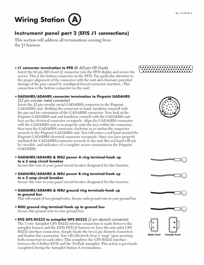
Instrument panel part 2 (EFIS J1 connections)This section will address all terminations coming from the J1 harness.
AWiring Station
• J1 connector termination to PFD J1 (62-pin HD D-sub) Insert the 62 pin HD d-sub J1 connector into the PFD display and secure the
screws. This is the bottom connector on the PFD. Pay particular attention to the proper alignment of the connector with the unit and eliminate potential damage of the pins caused by misaligned forced connector insertion. (This connection is the bottom connector on the unit).
• GADAHRS/ADAHRS connector termination to Pinpoint GADAHRS (22 pin circular metal connector)
Insert the 22 pin circular metal GADAHRS connector to the Pinpoint GADAHRS unit. Holding the connector in hand, familirize yourself with the pin and key orientation of the GADAHRS connector. Now look at the Pinpoint GADAHRS unit and familirize yourself with the GADAHRS unit keys on the electrical connector receptacle. Align the GADAHRS connector with the GADAHRS unit as to properly mate the keys within the connector, then turn the GADAHRS connector clockwise as to ratchet the connector securely to the Pinpoint GADAHRS unit. You will notice a red band around the Pinpoint GADAHRS electrical connector receptacle. Once you have properly ratcheted the GADAHRS connector securely to the unit this red band will not be viewable, and indicative of a complete secure connection to the Pinpoint GADAHRS.
• GADAHRS/ADAHRS & MSU power A ring terminal-hook up to a 5 amp circuit breaker
Secure this wire to your panel circuit breaker designated for this function.
• GADAHRS/ADAHRS & MSU power B ring terminal-hook up to a 5 amp circuit breaker
Secure this wire to your panel circuit breaker designated for this function.
• GADAHRS/ADAHRS & MSU ground ring terminals-hook up to ground bus
This will consist of two ground wires. Secure each ground wire to your ground bus.
• MSU ground ring terminal-hook up to ground bus Secure this ground wire to your ground bus.
• EFIS GPS RS232 to autopilot GPS RS232 (2 pin deutsch connector) The 3 wire Autopilot GPS RS232 interface connection is made between the
autopilot harness and the EFIS PFD J1 harness we have the auto pilot GPS RS232 interface connection. Simply locate the two 2 pin deutsch connectors and fi nalize this connection. You will effectively hear a “snap” upon securing both connectors to each other. This completes the GPS RS232 interface between the Chelton EFIS and the TruTrak Autopilot. This action is previously completed during the Autopilot Station A terminations.
Male front Female front
Rev 10.26.06 A
1
2
1
2
Male front Female front
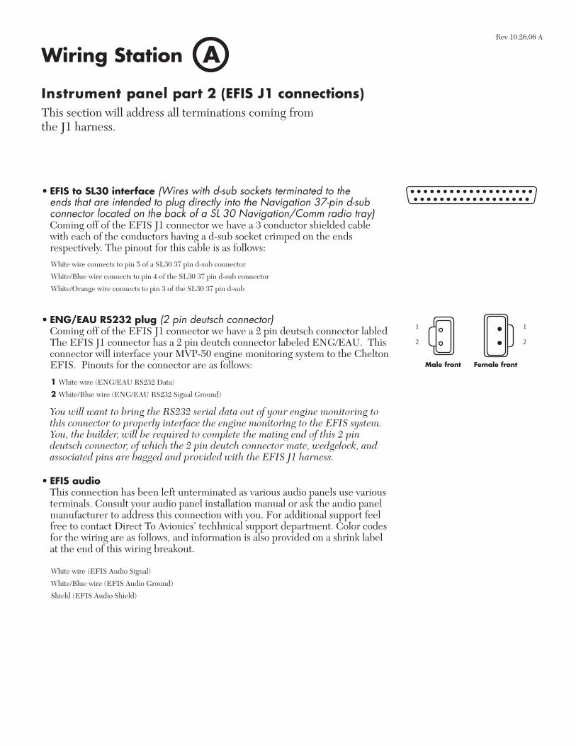
Instrument panel part 2 (EFIS J1 connections)This section will address all terminations coming from the J1 harness.
AWiring Station
• EFIS to SL30 interface (Wires with d-sub sockets terminated to the ends that are intended to plug directly into the Navigation 37-pin d-sub connector located on the back of a SL 30 Navigation/Comm radio tray)
Coming off of the EFIS J1 connector we have a 3 conductor shielded cable with each of the conductors having a d-sub socket crimped on the ends respectively. The pinout for this cable is as follows:
• ENG/EAU RS232 plug (2 pin deutsch connector)Coming off of the EFIS J1 connector we have a 2 pin deutsch connector labled The EFIS J1 connector has a 2 pin deutch connector labeled ENG/EAU. This connector will interface your MVP-50 engine monitoring system to the Chelton EFIS. Pinouts for the connector are as follows:
You will want to bring the RS232 serial data out of your engine monitoring to
this connector to properly interface the engine monitoring to the EFIS system. You, the builder, will be required to complete the mating end of this 2 pin deutsch connector, of which the 2 pin deutch connector mate, wedgelock, and associated pins are bagged and provided with the EFIS J1 harness.
• EFIS audioThis connection has been left unterminated as various audio panels use various terminals. Consult your audio panel installation manual or ask the audio panel manufacturer to address this connection with you. For additional support feel free to contact Direct To Avionics’ techhnical support department. Color codes for the wiring are as follows, and information is also provided on a shrink label at the end of this wiring breakout.
1 White wire (ENG/EAU RS232 Data)
2 White/Blue wire (ENG/EAU RS232 Signal Ground)
White wire connects to pin 5 of a SL30 37 pin d-sub connector
White/Blue wire connects to pin 4 of the SL30 37 pin d-sub connector
White/Orange wire connects to pin 3 of the SL30 37 pin d-sub
White wire (EFIS Audio Signal)
White/Blue wire (EFIS Audio Ground)
Shield (EFIS Audio Shield)
Rev 10.26.06 A
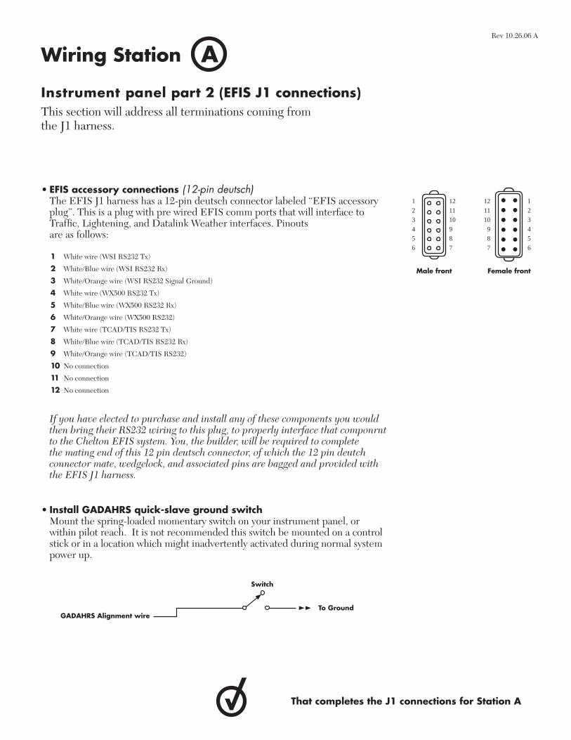
• EFIS accessory connections (12-pin deutsch)The EFIS J1 harness has a 12-pin deutsch connector labeled “EFIS accessory plug”. This is a plug with pre wired EFIS comm ports that will interface to Traffi c, Lightening, and Datalink Weather interfaces. Pinouts are as follows:
1
2
3
4
5
6
1
2
3
4
5
6
12
11
10
9
8
7
12
11
10
9
8
7
Male front Female front
1 White wire (WSI RS232 Tx)
2 White/Blue wire (WSI RS232 Rx)
3 White/Orange wire (WSI RS232 Signal Ground)
4 White wire (WX500 RS232 Tx)
5 White/Blue wire (WX500 RS232 Rx)
6 White/Orange wire (WX500 RS232)
7 White wire (TCAD/TIS RS232 Tx)
8 White/Blue wire (TCAD/TIS RS232 Rx)
9 White/Orange wire (TCAD/TIS RS232)
10 No connection
11 No connection
12 No connection
Instrument panel part 2 (EFIS J1 connections)This section will address all terminations coming from the J1 harness.
AWiring Station
If you have elected to purchase and install any of these components you would then bring their RS232 wiring to this plug, to properly interface that componrnt to the Chelton EFIS system. You, the builder, will be required to complete the mating end of this 12 pin deutsch connector, of which the 12 pin deutch connector mate, wedgelock, and associated pins are bagged and provided with the EFIS J1 harness.
• Install GADAHRS quick-slave ground switch Mount the spring-loaded momentary switch on your instrument panel, or
within pilot reach. It is not recommended this switch be mounted on a control stick or in a location which might inadvertently activated during normal system power up.
That completes the J1 connections for Station A
GADAHRS Alignment wireTo Ground
Switch
Rev 10.26.06 A
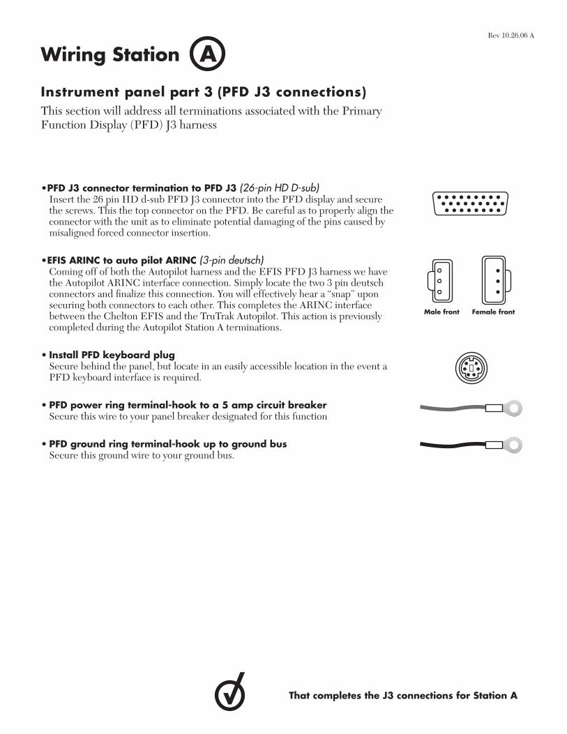
•PFD J3 connector termination to PFD J3 (26-pin HD D-sub) Insert the 26 pin HD d-sub PFD J3 connector into the PFD display and secure
the screws. This the top connector on the PFD. Be careful as to properly align the connector with the unit as to eliminate potential damaging of the pins caused by misaligned forced connector insertion.
•EFIS ARINC to auto pilot ARINC (3-pin deutsch) Coming off of both the Autopilot harness and the EFIS PFD J3 harness we have
the Autopilot ARINC interface connection. Simply locate the two 3 pin deutsch connectors and fi nalize this connection. You will effectively hear a “snap” upon securing both connectors to each other. This completes the ARINC interface between the Chelton EFIS and the TruTrak Autopilot. This action is previously completed during the Autopilot Station A terminations.
• Install PFD keyboard plug Secure behind the panel, but locate in an easily accessible location in the event a
PFD keyboard interface is required.
• PFD power ring terminal-hook to a 5 amp circuit breaker Secure this wire to your panel breaker designated for this function
• PFD ground ring terminal-hook up to ground bus Secure this ground wire to your ground bus.
Instrument panel part 3 (PFD J3 connections) This section will address all terminations associated with the Primary Function Display (PFD) J3 harness
AWiring Station
Male front Female front
That completes the J3 connections for Station A
Rev 10.26.06 A
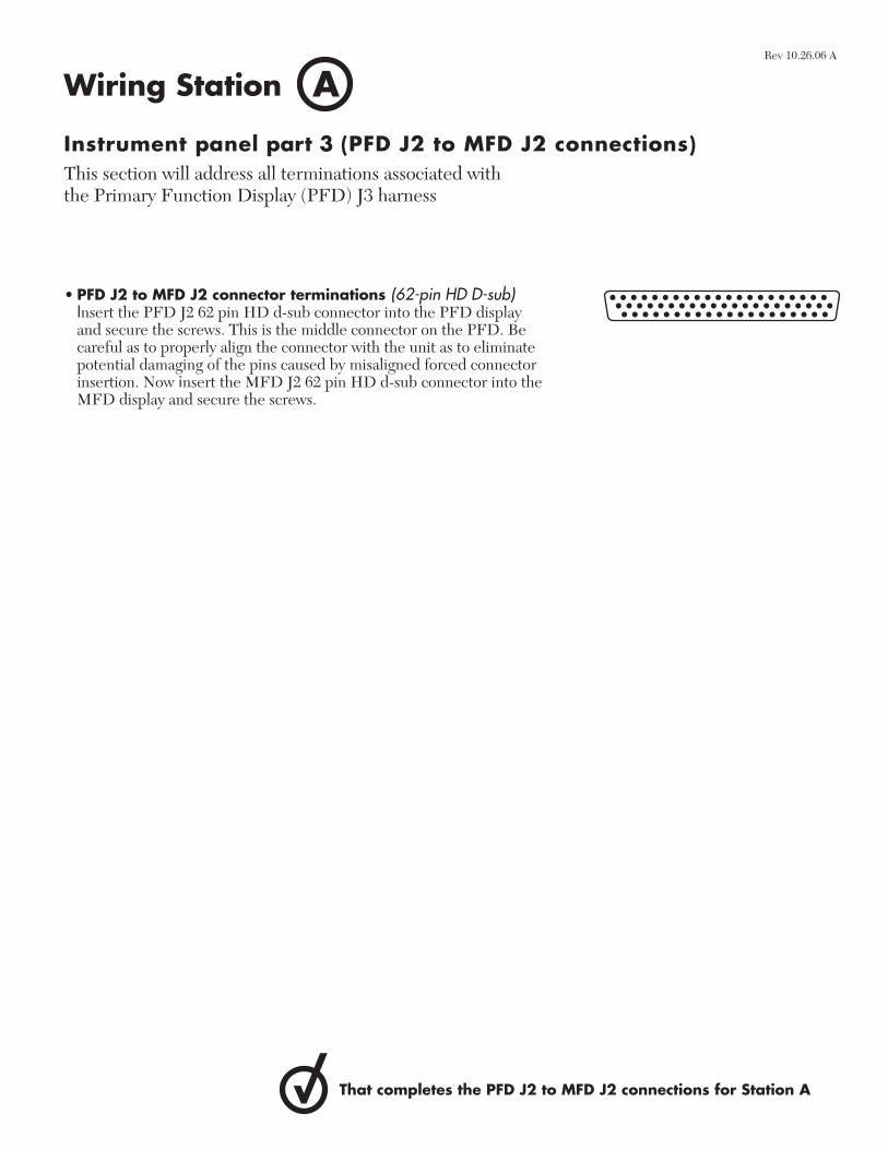
• PFD J2 to MFD J2 connector terminations (62-pin HD D-sub) Insert the PFD J2 62 pin HD d-sub connector into the PFD display
and secure the screws. This is the middle connector on the PFD. Be careful as to properly align the connector with the unit as to eliminate potential damaging of the pins caused by misaligned forced connector insertion. Now insert the MFD J2 62 pin HD d-sub connector into the MFD display and secure the screws.
Instrument panel part 3 (PFD J2 to MFD J2 connections) This section will address all terminations associated with the Primary Function Display (PFD) J3 harness
AWiring Station
That completes the PFD J2 to MFD J2 connections for Station A
Rev 10.26.06 A
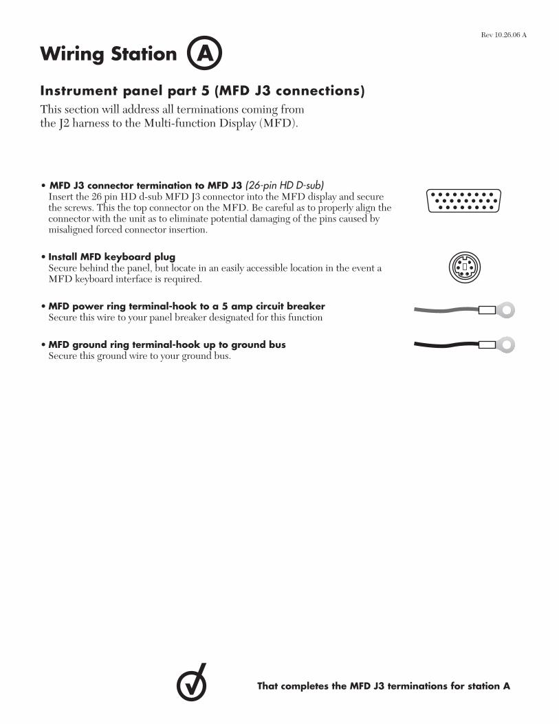
• MFD J3 connector termination to MFD J3 (26-pin HD D-sub) Insert the 26 pin HD d-sub MFD J3 connector into the MFD display and secure
the screws. This the top connector on the MFD. Be careful as to properly align the connector with the unit as to eliminate potential damaging of the pins caused by misaligned forced connector insertion.
• Install MFD keyboard plug Secure behind the panel, but locate in an easily accessible location in the event a
MFD keyboard interface is required.
• MFD power ring terminal-hook to a 5 amp circuit breaker Secure this wire to your panel breaker designated for this function
• MFD ground ring terminal-hook up to ground bus Secure this ground wire to your ground bus.
Instrument panel part 5 (MFD J3 connections) This section will address all terminations coming from the J2 harness to the Multi-function Display (MFD).
AWiring Station
That completes the MFD J3 terminations for station A
Rev 10.26.06 A
Right side fuselage to wing harness
• Right side door ajar annunciator (22 AWG)Wire has been left unterminated with no connector or terminal supplied. This wire is required to go to the Pilot Door Ajar warning light if you have made provisions for this annunciator on your panel.
• Right door ajar annunciator ground (22 AWG)Wire has been left unterminated with no connector or terminal supplied. This wire is required to go to ground if you have made provisions for this annunciator on your panel.
• Right side landing light power (two 16 AWG power wires supplied) Wire has been left unterminated with no connector or terminal supplied. This wire is required to go to the landing light switch if you have made provisions for this function on your panel.
• Pitot heat power (14 AWG)Wire has been left unterminated with no connector or terminal supplied. This wire is required to go to the Pitot Heat switch on your panel.
• Right side navigation light power (20 AWG)Wire has been left unterminated with no connector or terminal supplied.This wire is required to go to the navigation light switch on your panel.
• Aileron trim motor (two 22 AWG motor wires supplied)Wires have been left unterminated with no connector or terminal supplied. This wire is required to go to the Aileron Trim relay deck and is intended to interface to the trim system, none of which is provided by Direct To Avionics. Completion of the overall trim system is up to you the builder.
• Strobe pack power (18 AWG)Wire has been left unterminated with no connector or terminal supplied. This wire is required to go to the strobe power switch on your panel.
• Strobe pack ground (18 AWG)Wire has been left unterminated with no connector or terminal supplied. This wire is required to go to the nearest ground bus.
• Elevator trim 5 conductor (22 AWG) Wires have been left unterminated with no connector or terminals supplied. This wire is required to go to the Aileron Trim relay deck and is intended to interface to the trim system, none of which is provided by Direct To Avionics. Completion of the overall trim system is up to you the builder.
• Tail navigation light power (20 AWG)Wire has been left unterminated with no connector or terminal supplied. This wire is required to go to the navigation light switch on your panel.
Final routing and connections part 6 The remainder of these Station A terminations will need to be fi nished by the builder. This includes the fuselage to pilot wing harness piece and the fuselage to right side wing harness piece. We have supplied ample length of wire for these tasks. Be sure to purchase appropriate connectors and make the proper connections as directed by your panel to airframe interface and personal aircraft function preference in regards to electrical terminations.
AWiring StationRev 10.26.06 A
Right side fuselage to wing harness
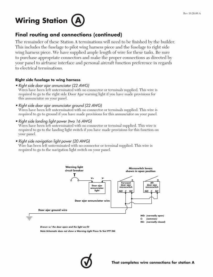
• Right side door ajar annunciator (22 AWG)Wires have been left unterminated with no connector or terminals supplied. This wire is required to go to the right side Door Ajar warning light if you have made provisions for this annunciator on your panel.
• Right side door ajar annunciator ground (22 AWG) Wires have been left unterminated with no connector or terminals supplied. This wire is required to go to ground if you have made provisions for this annunciator on your panel.
• Right side landing light power (two 16 AWG)Wires have been left unterminated with no connector or terminal supplied. This wire is required to go to the landing light switch if you have made provisions for this function on your panel.
• Right side navigation light power (20 AWG)Wire has been left unterminated with no connector or terminal supplied. This wire is required to go to the navigation light switch on your panel.
Final routing and connections (continued) The remainder of these Station A terminations will need to be fi nished by the builder. This includes the fuselage to pilot wing harness piece and the fuselage to right side wing harness piece. We have supplied ample length of wire for these tasks. Be sure to purchase appropriate connectors and make the proper connections as directed by your panel to airframe interface and personal aircraft function preference in regards to electrical terminations.
AWiring Station
That completes wire connections for station A
Warning lightcircuit breaker
Door ajar ground wire
Door ajarannunciator
light
Forward door ajar
microswitch
Aft door ajar
microswitch
Microswitch levers shown in open position
NO: (normally open)C: (common)NC: (normally closed)
C
V+ V-
NO NCCNO NC
Door ajar annunciator wire
Drawn w/ the door open and the light on/lit
Note-Schematic does not show a Warning Light Press To Test PTT SW.
Rev 10.26.06 A
FreeFlight GPS receiver (optional)The instrument panel section is broken out in several parts with different tasks to complete. Read below for a step-by-step guide on beginning and completing this station.
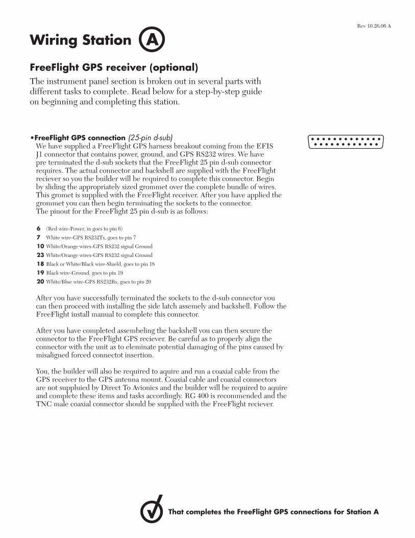
•FreeFlight GPS connection (25-pin d-sub) We have supplied a FreeFlight GPS harness breakout coming from the EFIS
J1 connector that contains power, ground, and GPS RS232 wires. We have pre terminated the d-sub sockets that the FreeFlight 25 pin d-sub connector requires. The actual connector and backshell are supplied with the FreeFlight reciever so you the builder will be required to complete this connector. Begin by sliding the appropriately sized grommet over the complete bundle of wires. This gromet is supplied with the FreeFlight receiver. After you have applied the grommet you can then begin terminating the sockets to the connector. The pinout for the FreeFlight 25 pin d-sub is as follows:
After you have successfully terminated the sockets to the d-sub connector you can then proceed with installing the side latch assemely and backshell. Follow the FreeFlight install manual to complete this connector.
After you have completed assembeling the backshell you can then secure the connector to the FreeFlight GPS reciever. Be careful as to properly align the connector with the unit as to eleminate potential damaging of the pins caused by misaligned forced connectot insertion.
You, the builder will also be required to aquire and run a coaxial cable from the GPS receiver to the GPS antenna mount. Coaxial cable and coaxial connectors are not suppluied by Direct To Avionics and the builder will be required to aquire and complete these items and tasks accordingly. RG 400 is recommended and the TNC male coaxial connector should be supplied with the FreeFlight reciever.
AWiring Station
That completes the FreeFlight GPS connections for Station A
6 (Red wire-Power, in goes to pin 6)
7 White wire-GPS RS232Tx, goes to pin 7
10 White/Orange wires-GPS RS232 signal Ground
23 White/Orange wires-GPS RS232 signal Ground
18 Black or White/Black wire-Shield, goes to pin 18
19 Black wire-Ground, goes to pin 19
20 White/Blue wire-GPS RS232Rx, goes to pin 20
Rev 10.26.06 A
BWiring Station
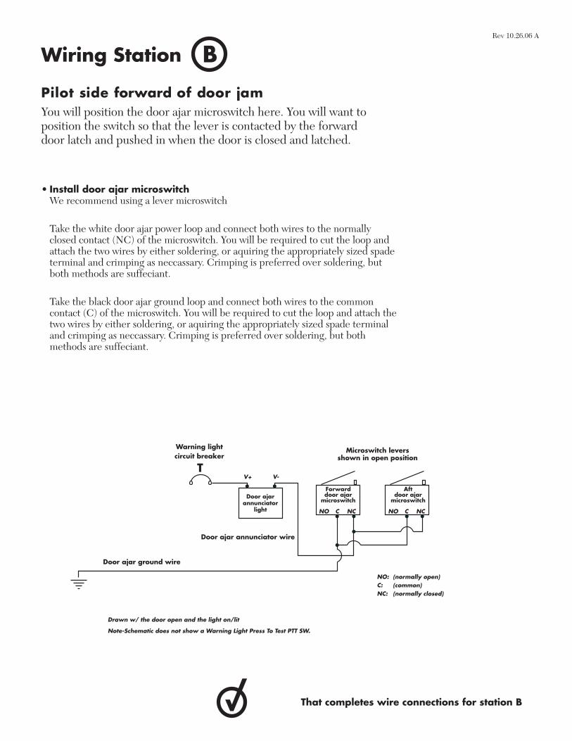
Pilot side forward of door jamYou will position the door ajar microswitch here. You will want to position the switch so that the lever is contacted by the forward door latch and pushed in when the door is closed and latched.
• Install door ajar microswitch We recommend using a lever microswitch
Take the white door ajar power loop and connect both wires to the normally closed contact (NC) of the microswitch. You will be required to cut the loop and attach the two wires by either soldering, or aquiring the appropriately sized spade terminal and crimping as neccassary. Crimping is preferred over soldering, but both methods are suffeciant.
Take the black door ajar ground loop and connect both wires to the common contact (C) of the microswitch. You will be required to cut the loop and attach the two wires by either soldering, or aquiring the appropriately sized spade terminal and crimping as neccassary. Crimping is preferred over soldering, but both methods are suffeciant.
That completes wire connections for station B
Warning lightcircuit breaker
Door ajar ground wire
Door ajarannunciator
light
Forward door ajar
microswitch
Aft door ajar
microswitch
Microswitch levers shown in open position
NO: (normally open)C: (common)NC: (normally closed)
C
V+ V-
NO NCCNO NC
Door ajar annunciator wire
Drawn w/ the door open and the light on/lit
Note-Schematic does not show a Warning Light Press To Test PTT SW.
Rev 10.26.06 A

CWiring Station
Left side aft of door jamYou will position the door ajar microswitch here. You will want to position the switch so that the lever is contacted by the forward door latch and pushed in when the door is closed and latched.
• Install door ajar microswitch We recommend using a lever microswitch
Take the white door ajar power loop and connect both wires to the normally closed contact (NC) of the microswitch. You will be required to cut the loop and attach the two wires by either soldering, or aquiring the appropriately sized spade terminal and crimping as neccassary. Crimping is preferred over soldering, but both methods are suffeciant.
Take the black door ajar ground loop and connect both wires to the common contact (C) of the microswitch. You will be required to cut the loop and attach the two wires by either soldering, or aquiring the appropriately sized spade terminal and crimping as neccassary. Crimping is preferred over soldering, but both methods are suffeciant.
That completes wire connections for station C
Warning lightcircuit breaker
Door ajar ground wire
Door ajarannunciator
light
Forward door ajar
microswitch
Aft door ajar
microswitch
Microswitch levers shown in open position
NO: (normally open)C: (common)NC: (normally closed)
C
V+ V-
NO NCCNO NC
Door ajar annunciator wire
Drawn w/ the door open and the light on/lit
Note-Schematic does not show a Warning Light Press To Test PTT SW.
Rev 10.26.06 A

DWiring Station
Right side side aft of door jamYou will position the door ajar microswitch here. You will want to position the switch so that the lever is contacted by the forward door latch and pushed in when the door is closed and latched.
• Install door ajar microswitch We recommend using a lever microswitch
Take the white door ajar power loop and connect both wires to the normally closed contact (NC) of the microswitch. You will be required to cut the loop and attach the two wires by either soldering, or aquiring the appropriately sized spade terminal and crimping as neccassary. Crimping is preferred over soldering, but both methods are suffeciant.
Take the black door ajar ground loop and connect both wires to the common contact (C) of the microswitch. You will be required to cut the loop and attach the two wires by either soldering, or aquiring the appropriately sized spade terminal and crimping as neccassary. Crimping is preferred over soldering, but both methods are suffeciant.
That completes wire connections for station D
Warning lightcircuit breaker
Door ajar ground wire
Door ajarannunciator
light
Forward door ajar
microswitch
Aft door ajar
microswitch
Microswitch levers shown in open position
NO: (normally open)C: (common)NC: (normally closed)
C
V+ V-
NO NCCNO NC
Door ajar annunciator wire
Drawn w/ the door open and the light on/lit
Note-Schematic does not show a Warning Light Press To Test PTT SW.
Rev 10.26.06 A

EWiring Station
Left side aft of door jamYou will position the door ajar microswitch here. You will want to position the switch so that the lever is contacted by the forward door latch and pushed in when the door is closed and latched.
• Install door ajar microswitch We recommend using a lever microswitch
Take the white door ajar power loop and connect both wires to the normally Closed contact (NC) of the microswitch. You will be required to cut the loop and attach the two wires by either soldering, or aquiring the appropriately sized spade terminal and crimping as neccassary. Crimping is preferred over soldering, but both methods are suffeciant.
Take the black door ajar ground loop and connect both wires to the common contact (C) of the microswitch. You will be required to cut the loop and attach the two wires by either soldering, or aquiring the appropriately sized spade terminal and crimping as neccassary. Crimping is preferred over soldering, but both methods are suffeciant.
That completes wire connections for station E
Warning lightcircuit breaker
Door ajar ground wire
Door ajarannunciator
light
Forward door ajar
microswitch
Aft door ajar
microswitch
Microswitch levers shown in open position
NO: (normally open)C: (common)NC: (normally closed)
C
V+ V-
NO NCCNO NC
Door ajar annunciator wire
Drawn w/ the door open and the light on/lit
Note-Schematic does not show a Warning Light Press To Test PTT SW.
Rev 10.26.06 A
FWiring Station
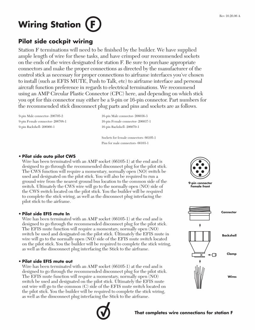
Pilot side cockpit wiringStation F terminations will need to be fi nished by the builder. We have supplied ample length of wire for these tasks, and have crimped our recommended sockets on the ends of the wires designated for station F. Be sure to purchase appropriate connectors and make the proper connections as directed by the manufacturer of the control stick as necessary for proper connections to airframe interfaces you’ve chosen to install (such as EFIS MUTE, Push to Talk, etc) to airframe interface and personal aircraft function preference in regards to electrical terminations. We recommend using an AMP Circular Plastic Connector (CPC) here, and depending on which stick you opt for this connector may either be a 9-pin or 16-pin connector. Part numbers for the recommended stick dissconnect plug parts and pins and sockets are as follows.
• Pilot side auto pilot CWS Wire has been terminated with an AMP socket (66105-1) at the end and is
designed to go through the recommended disconnect plug for the pilot stick. The CWS function will require a momentary, normally open (NO) switch be used and designated on the pilot stick. You will also be required to run a ground wire from the nearest ground bus location to the common side of the switch. Ultimately the CWS wire will go to the normally open (NO) side of the CWS switch located on the pilot stick. You the builder will be required to complete the stick wiring, as well as the disconnect plug interfacing the pilot stick to the airframe.
• Pilot side EFIS mute In Wire has been terminated with an AMP socket (66105-1) at the end and is
designed to go through the recommended disconnect plug for the pilot stick. The EFIS mute function will require a momentary, normally open (NO) switch be used and designated on the pilot stick. Ultimately the EFIS mute in wire will go to the normally open (NO) side of the EFIS mute switch located on the pilot stick. You the builder will be required to complete the stick wiring, as well as the dissconnect plug interfacing the Stick to the airframe.
• Pilot side EFIS mute out Wire has been terminated with an AMP socket (66105-1) at the end and is
designed to go through the recommended disconnect plug for the pilot stick. The EFIS mute function will require a momentary, normally open (NO) switch be used and designated on the pilot stick. Ultimately the EFIS mute out wire will go to the common (C) side of the EFIS mute switch located on the pilot stick. You the builder will be required to complete the stick wiring, as well as the dissconnect plug interfacing the Stick to the airframe.
9-pin Male connector- 206705-2
9-pin Female connector- 206708-1
9-pin Backshell- 206966-1
16-pin Male connector- 206036-3
16-pin Female connector- 206037-1
16-pin Backshell- 206070-1
Sockets for female connectors- 66105-1
Pins for male connectors- 66103-1
That completes wire connections for station F
Wires
Backshell
Connector
Clamp
9-pin connectorFemale front
Rev 10.26.06 A
GWiring Station
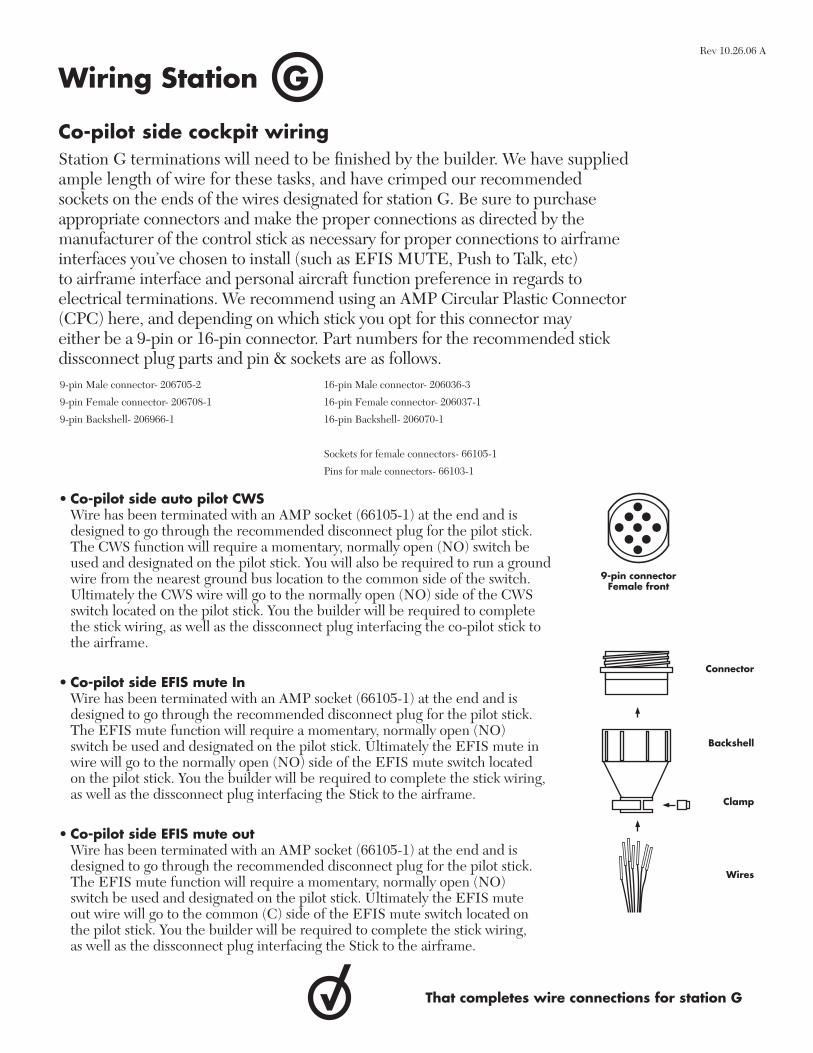
Co-pilot side cockpit wiringStation G terminations will need to be fi nished by the builder. We have supplied ample length of wire for these tasks, and have crimped our recommended sockets on the ends of the wires designated for station G. Be sure to purchase appropriate connectors and make the proper connections as directed by the manufacturer of the control stick as necessary for proper connections to airframe interfaces you’ve chosen to install (such as EFIS MUTE, Push to Talk, etc) to airframe interface and personal aircraft function preference in regards to electrical terminations. We recommend using an AMP Circular Plastic Connector (CPC) here, and depending on which stick you opt for this connector may either be a 9-pin or 16-pin connector. Part numbers for the recommended stick dissconnect plug parts and pin & sockets are as follows.
• Co-pilot side auto pilot CWS Wire has been terminated with an AMP socket (66105-1) at the end and is
designed to go through the recommended disconnect plug for the pilot stick. The CWS function will require a momentary, normally open (NO) switch be used and designated on the pilot stick. You will also be required to run a ground wire from the nearest ground bus location to the common side of the switch. Ultimately the CWS wire will go to the normally open (NO) side of the CWS switch located on the pilot stick. You the builder will be required to complete the stick wiring, as well as the dissconnect plug interfacing the co-pilot stick to the airframe.
• Co-pilot side EFIS mute In Wire has been terminated with an AMP socket (66105-1) at the end and is
designed to go through the recommended disconnect plug for the pilot stick. The EFIS mute function will require a momentary, normally open (NO) switch be used and designated on the pilot stick. Ultimately the EFIS mute in wire will go to the normally open (NO) side of the EFIS mute switch located on the pilot stick. You the builder will be required to complete the stick wiring, as well as the dissconnect plug interfacing the Stick to the airframe.
• Co-pilot side EFIS mute out Wire has been terminated with an AMP socket (66105-1) at the end and is
designed to go through the recommended disconnect plug for the pilot stick. The EFIS mute function will require a momentary, normally open (NO) switch be used and designated on the pilot stick. Ultimately the EFIS mute out wire will go to the common (C) side of the EFIS mute switch located on the pilot stick. You the builder will be required to complete the stick wiring, as well as the dissconnect plug interfacing the Stick to the airframe.
9-pin Male connector- 206705-2
9-pin Female connector- 206708-1
9-pin Backshell- 206966-1
16-pin Male connector- 206036-3
16-pin Female connector- 206037-1
16-pin Backshell- 206070-1
Sockets for female connectors- 66105-1
Pins for male connectors- 66103-1
That completes wire connections for station G
Wires
Backshell
Connector
Clamp
9-pin connectorFemale front
Rev 10.26.06 A
HWiring Station
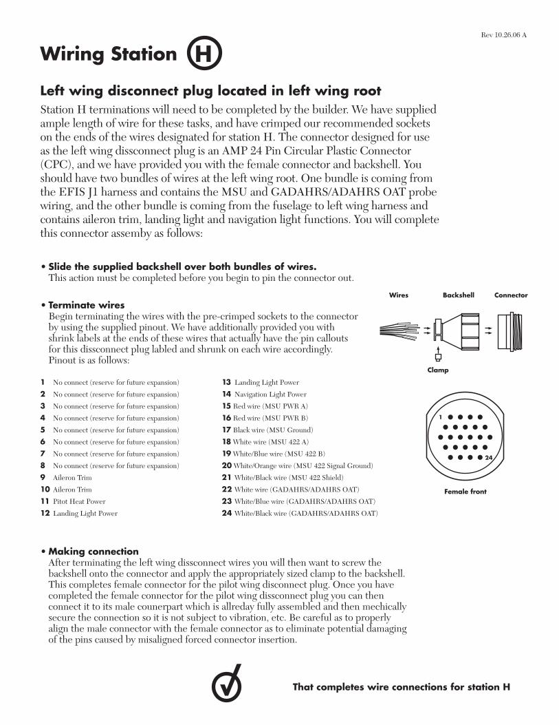
Left wing disconnect plug located in left wing rootStation H terminations will need to be completed by the builder. We have supplied ample length of wire for these tasks, and have crimped our recommended sockets on the ends of the wires designated for station H. The connector designed for use as the left wing dissconnect plug is an AMP 24 Pin Circular Plastic Connector (CPC), and we have provided you with the female connector and backshell. You should have two bundles of wires at the left wing root. One bundle is coming from the EFIS J1 harness and contains the MSU and GADAHRS/ADAHRS OAT probe wiring, and the other bundle is coming from the fuselage to left wing harness and contains aileron trim, landing light and navigation light functions. You will complete this connector assemby as follows:
• Slide the supplied backshell over both bundles of wires. This action must be completed before you begin to pin the connector out.
• Terminate wires Begin terminating the wires with the pre-crimped sockets to the connector
by using the supplied pinout. We have additionally provided you with shrink labels at the ends of these wires that actually have the pin callouts for this dissconnect plug labled and shrunk on each wire accordingly. Pinout is as follows:
1 No connect (reserve for future expansion)
2 No connect (reserve for future expansion)
3 No connect (reserve for future expansion)
4 No connect (reserve for future expansion)
5 No connect (reserve for future expansion)
6 No connect (reserve for future expansion)
7 No connect (reserve for future expansion)
8 No connect (reserve for future expansion)
9 Aileron Trim
10 Aileron Trim
11 Pitot Heat Power
12 Landing Light Power
13 Landing Light Power
14 Navigation Light Power
15 Red wire (MSU PWR A)
16 Red wire (MSU PWR B)
17 Black wire (MSU Ground)
18 White wire (MSU 422 A)
19 White/Blue wire (MSU 422 B)
20 White/Orange wire (MSU 422 Signal Ground)
21 White/Black wire (MSU 422 Shield)
22 White wire (GADAHRS/ADAHRS OAT)
23 White/Blue wire (GADAHRS/ADAHRS OAT)
24 White/Black wire (GADAHRS/ADAHRS OAT)
• Making connection After terminating the left wing dissconnect wires you will then want to screw the
backshell onto the connector and apply the appropriately sized clamp to the backshell. This completes female connector for the pilot wing disconnect plug. Once you have completed the female connector for the pilot wing dissconnect plug you can then connect it to its male counerpart which is allreday fully assembled and then mechically secure the connection so it is not subject to vibration, etc. Be careful as to properly align the male connector with the female connector as to eliminate potential damaging of the pins caused by misaligned forced connector insertion.
That completes wire connections for station H
• • • •• • • • •• • • • • •• • • • •• • • •
1
24
Wires Backshell Connector
Clamp
Female front
Rev 10.26.06 A
IWiring Station
Aileron trim servo locationStation I terminations will need to be fi nished by the builder. We have supplied ample length of wire for these tasks. Be sure to purchase the appropriate connector and make the proper connection as directed by your servo to airframe interface and personal aircraft function preference in regards to electrical terminations.
•Trim Motor Wires have been left unterminated with no connector or terminal supplied.
You will be required to connect the two harness wires to the two servo wires. In the event your aileron trim runs backwards, simply swap these two wires to reverse the servo direction. You the builder are responsible for the overall completion of the trim system.
That completes wire connections for station I
Rev 10.26.06 A
JWiring Station
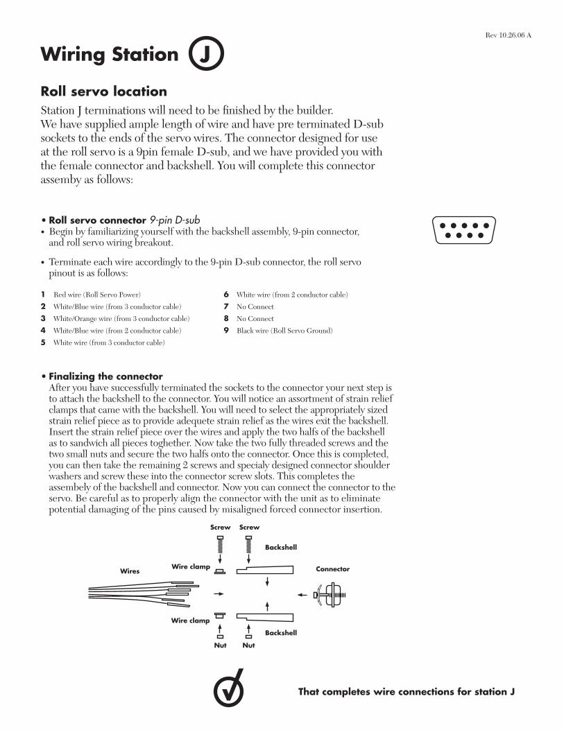
Roll servo locationStation J terminations will need to be fi nished by the builder. We have supplied ample length of wire and have pre terminated D-sub sockets to the ends of the servo wires. The connector designed for use at the roll servo is a 9pin female D-sub, and we have provided you with the female connector and backshell. You will complete this connector assemby as follows:
• Roll servo connector 9-pin D-sub• Begin by familiarizing yourself with the backshell assembly, 9-pin connector,
and roll servo wiring breakout.
• Terminate each wire accordingly to the 9-pin D-sub connector, the roll servo pinout is as follows:
That completes wire connections for station J
• Finalizing the connector After you have successfully terminated the sockets to the connector your next step is
to attach the backshell to the connector. You will notice an assortment of strain relief clamps that came with the backshell. You will need to select the appropriately sized strain relief piece as to provide adequete strain relief as the wires exit the backshell. Insert the strain relief piece over the wires and apply the two halfs of the backshell as to sandwich all pieces toghether. Now take the two fully threaded screws and the two small nuts and secure the two halfs onto the connector. Once this is completed, you can then take the remaining 2 screws and specialy designed connector shoulder washers and screw these into the connector screw slots. This completes the assembely of the backshell and connector. Now you can connect the connector to the servo. Be careful as to properly align the connector with the unit as to eliminate potential damaging of the pins caused by misaligned forced connector insertion.
1 Red wire (Roll Servo Power)
2 White/Blue wire (from 3 conductor cable)
3 White/Orange wire (from 3 conductor cable)
4 White/Blue wire (from 2 conductor cable)
5 White wire (from 3 conductor cable)
6 White wire (from 2 conductor cable)
7 No Connect
8 No Connect
9 Black wire (Roll Servo Ground)
Rev 10.26.06 A
Backshell
Connector
Nut
Backshell
Screw
Wire clamp
Nut
Wires
Screw
Wire clamp
KWiring Station
Pitot tube locationDepending on your pitot tube mount, it may be further outboard than inboard on the wing, or vice versa. In order to accomadate both mounts Direct To Avionics has provided you the builder with an ample length of wire for this task. You will want to to purchase the appropriate connector and make the proper connection as directed by your pitot tube to airframe interface and personal aircraft function preference in regards to electrical terminations. If your pitot tube is inboard as opposed to outboard you will want to cut off any access wire and then apply the terminal or connector as necessary. You, the builder will be required to run a ground wire to the nearest ground bus for the pitot tube as well.
That completes wire connections for station K
Rev 10.26.06 A
LWiring Station
Left wing tipStation L terminations will need to be fi nished by the builder. We have supplied ample length of wire for the task. Be sure to purchase suitable connectors and make the proper connections as directed by your airframe to various light assembely interfaces and personal aircraft function.
• GADAHRS OAT Wires have been left unterminated with no connector or terminal supplied.
The OAT connector and terminals will be supplied with the Pinpoint GADAHRS. Plese refer to the Direct To Avionics OAT assebly manual for complete instructions on completing this connection.
• Left navigation light power Wire has been left unterminated with no connector or terminal supplied. You will
be required to connect this to the navigation light power wire. You, the builder will be required to run a ground wire to the nearest ground bus for the navigation light as well.
• Left landing light power (two wires supplied here) Wires have been left unterminated with no connector or terminal supplied. You will
be required to connect these wires to the landing light power wire. You, the builder will be required to run a ground wire to the nearest ground bus for the landing light as well. If you have high intensity discharge (HID’s) landing lights you will want to run the powers to the ballast fi rst. You would still be required to run the ground from the nearest ground bus to the ballast as well. From there, the manufacturer of the landing light should provide you with a harness that will connect the ballast to the actual landing light.
• Strobe light Wires have been pre terminated with the strobe light sockets that will properly
mate with the strobe light receptacle. The connector for the light assembly should be included with your strobe light kit. If not, you the builder will need to obtain the proper connector. Our recommended color coding for the strobe lights are as follows:
1 Red wire on light-Anode function- White/Orange wire on 3 conductor shielded cable
2 Black wire on light-Cathode function-White/Blue wire on 3 conductor shielded cable
3 White wire on light-Trigger function-White wire on 3 conductor shielded cable
Shield will be left open (I.E no connect) at the wing tip.
Rev 10.26.06 A
LWiring Station
Left wing tip (continued)Station L terminations will need to be fi nished by the builder. We have supplied ample length of wire for the task. Be sure to purchase suitable connectors and make the proper connections as directed by your airframe to various light assembely interfaces and personal aircraft function.
That completes wire connections for station L
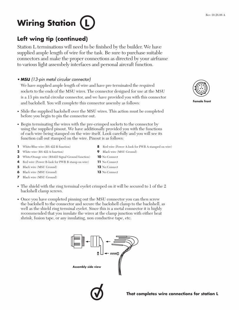
• MSU (13-pin metal circular connector) We have supplied ample length of wire and have pre terminated the required
sockets to the ends of the MSU wires. The connector designed for use at the MSU is a 13 pin metal circular connector, and we have provided you with this connector and backshell. You will complete this connector assemby as follows:
• Slide the supplied backshell over the MSU wires. This action must be completed before you begin to pin the connector out.
• Begin terminating the wires with the pre-crimped sockets to the connector by using the supplied pinout. We have additionally provided you with the functions of each wire being stamped on the wire itself. Look carefully and you will see its function call out stamped on the wire. Pinout is as follows:
1 White/Blue wire (RS 422 B function)
2 White wire (RS 422 A function)
3 White/Orange wire (RS422 Signal Ground function)
4 Red wire (Power B-look for PWR B stamp on wire)
5 Black wire (MSU Ground)
6 Black wire (MSU Ground)
7 Black wire (MSU Ground)
8 Red wire (Power A-look for PWR A stamped on wire)
9 Black wire (MSU Ground)
10 No Connect
11 No Connect
12 No Connect
13 No Connect
• The shield with the ring terminal eyelet crimped on it will be secured to 1 of the 2 backshell clamp screws.
• Once you have completed pinning out the MSU connector you can then screw the backshell to the connector and secure the backshell clamp to the backshell, as well as the shield ring terminal eyelet. Since this is a metal connector it is highly recommended that you insulate the wires at the clamp junction with either heat shrink, fusion tape, or any insulating, non conductive tape, etc.
Female front
Assembly side view
Rev 10.26.06 A
MWiring Station
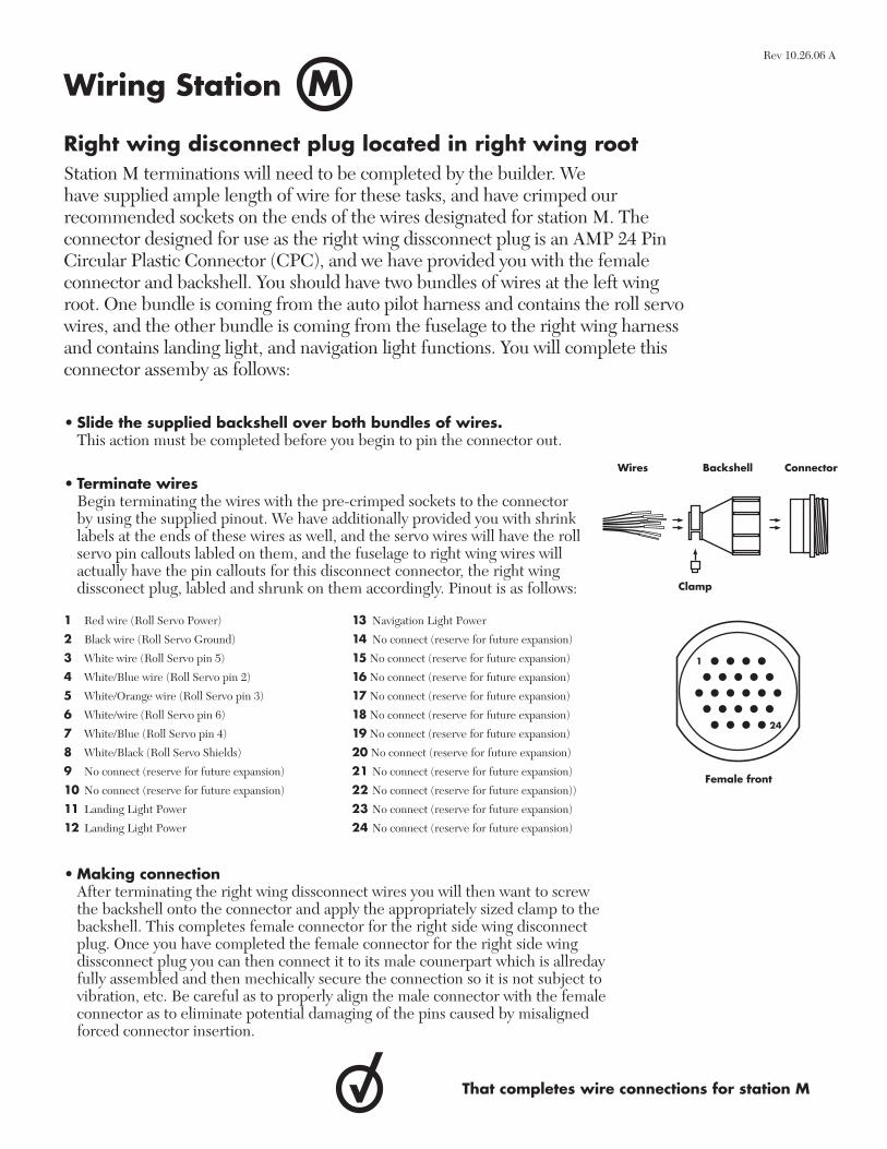
• Slide the supplied backshell over both bundles of wires. This action must be completed before you begin to pin the connector out.
• Terminate wires Begin terminating the wires with the pre-crimped sockets to the connector
by using the supplied pinout. We have additionally provided you with shrink labels at the ends of these wires as well, and the servo wires will have the roll servo pin callouts labled on them, and the fuselage to right wing wires will actually have the pin callouts for this disconnect connector, the right wing dissconect plug, labled and shrunk on them accordingly. Pinout is as follows:
1 Red wire (Roll Servo Power)
2 Black wire (Roll Servo Ground)
3 White wire (Roll Servo pin 5)
4 White/Blue wire (Roll Servo pin 2)
5 White/Orange wire (Roll Servo pin 3)
6 White/wire (Roll Servo pin 6)
7 White/Blue (Roll Servo pin 4)
8 White/Black (Roll Servo Shields)
9 No connect (reserve for future expansion)
10 No connect (reserve for future expansion)
11 Landing Light Power
12 Landing Light Power
13 Navigation Light Power
14 No connect (reserve for future expansion)
15 No connect (reserve for future expansion)
16 No connect (reserve for future expansion)
17 No connect (reserve for future expansion)
18 No connect (reserve for future expansion)
19 No connect (reserve for future expansion)
20 No connect (reserve for future expansion)
21 No connect (reserve for future expansion)
22 No connect (reserve for future expansion))
23 No connect (reserve for future expansion)
24 No connect (reserve for future expansion)
• Making connection After terminating the right wing dissconnect wires you will then want to screw
the backshell onto the connector and apply the appropriately sized clamp to the backshell. This completes female connector for the right side wing disconnect plug. Once you have completed the female connector for the right side wing dissconnect plug you can then connect it to its male counerpart which is allreday fully assembled and then mechically secure the connection so it is not subject to vibration, etc. Be careful as to properly align the male connector with the female connector as to eliminate potential damaging of the pins caused by misaligned forced connector insertion.
That completes wire connections for station M
• • • •• • • • •• • • • • •• • • • •• • • •
1
24
Wires Backshell Connector
Clamp
Female front
Right wing disconnect plug located in right wing rootStation M terminations will need to be completed by the builder. We have supplied ample length of wire for these tasks, and have crimped our recommended sockets on the ends of the wires designated for station M. The connector designed for use as the right wing dissconnect plug is an AMP 24 Pin Circular Plastic Connector (CPC), and we have provided you with the female connector and backshell. You should have two bundles of wires at the left wing root. One bundle is coming from the auto pilot harness and contains the roll servo wires, and the other bundle is coming from the fuselage to the right wing harness and contains landing light, and navigation light functions. You will complete this connector assemby as follows:
Rev 10.26.06 A
NWiring Station
Right wing tipStation N terminations will need to be fi nished by the builder. We have supplied ample length of wire for the task. Be sure to purchase suitable connectors and make the proper connections as directed by your airframe to various light assembely interfaces and personal aircraft function.
• Right side navigation light power Wire has been left unterminated with no connector or terminal supplied. You will be
required to connect this to the navigation light power wire. You, the builder will be required to run a ground wire to the nearest ground bus for the navigation light as well.
• Right side landing light power (two wires supplied here) Wires have been left unterminated with no connector or terminal supplied. You will
be required to connect these wires to the landing light power wire. You, the builder will be required to run a ground wire to the nearest ground bus for the landing light as well. If you have high intensity discharge (hid’s) landing lights you will want to run the powers to the ballast fi rst. You would still be required to run the ground from the nearest ground bus to the ballast as well. From there, the manufacturer of the landing light should provide you with a harness that will connect the ballast to the actual landing light.
• Strobe light Wires have been pre terminated with the strobe light sockets that will properly
mate with the strobe light receptacle. The connector for the light assembly should be included with your strobe light kit. If not, you the builder will need to obtain the proper connector. Our recommended color coding for the strobe lights are as follows:
1 Red wire on light-Anode function- White/Orange wire on 3 conductor shielded cable
2 Black wire on light-Cathode function-White/Blue wire on 3 conductor shielded cable
3 White wire on light-Trigger function-White wire on 3 conductor shielded cable
Shield will be left open (I.E no connect) at the wing tip.
That completes wire connections for station N
Rev 10.26.06 A
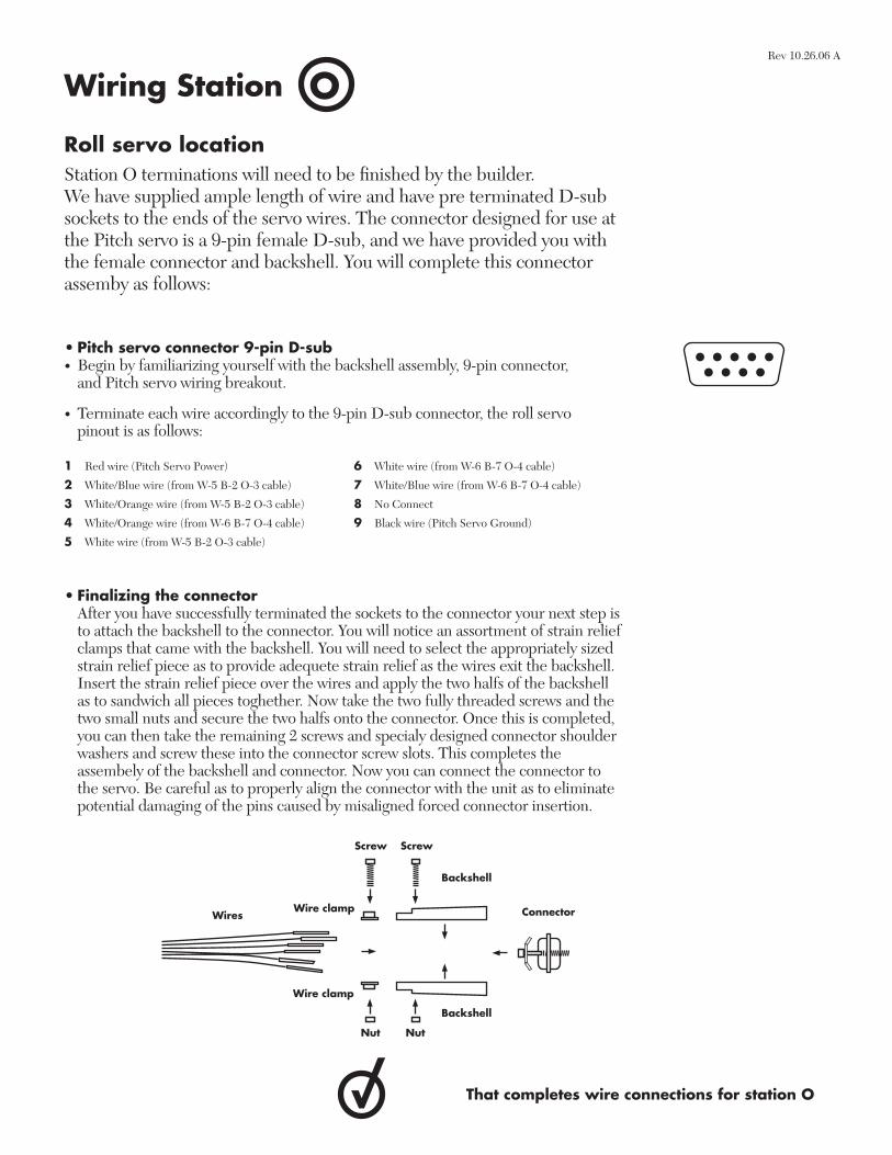
Roll servo locationStation O terminations will need to be fi nished by the builder. We have supplied ample length of wire and have pre terminated D-sub sockets to the ends of the servo wires. The connector designed for use at the Pitch servo is a 9-pin female D-sub, and we have provided you with the female connector and backshell. You will complete this connector assemby as follows:
• Pitch servo connector 9-pin D-sub• Begin by familiarizing yourself with the backshell assembly, 9-pin connector,
and Pitch servo wiring breakout.
• Terminate each wire accordingly to the 9-pin D-sub connector, the roll servo pinout is as follows:
• Finalizing the connector After you have successfully terminated the sockets to the connector your next step is
to attach the backshell to the connector. You will notice an assortment of strain relief clamps that came with the backshell. You will need to select the appropriately sized strain relief piece as to provide adequete strain relief as the wires exit the backshell. Insert the strain relief piece over the wires and apply the two halfs of the backshell as to sandwich all pieces toghether. Now take the two fully threaded screws and the two small nuts and secure the two halfs onto the connector. Once this is completed, you can then take the remaining 2 screws and specialy designed connector shoulder washers and screw these into the connector screw slots. This completes the assembely of the backshell and connector. Now you can connect the connector to the servo. Be careful as to properly align the connector with the unit as to eliminate potential damaging of the pins caused by misaligned forced connector insertion.
1 Red wire (Pitch Servo Power)
2 White/Blue wire (from W-5 B-2 O-3 cable)
3 White/Orange wire (from W-5 B-2 O-3 cable)
4 White/Orange wire (from W-6 B-7 O-4 cable)
5 White wire (from W-5 B-2 O-3 cable)
6 White wire (from W-6 B-7 O-4 cable)
7 White/Blue wire (from W-6 B-7 O-4 cable)
8 No Connect
9 Black wire (Pitch Servo Ground)
OWiring Station
That completes wire connections for station O
Rev 10.26.06 A
Backshell
Connector
Nut
Backshell
Screw
Wire clamp
Nut
Wires
Screw
Wire clamp
PWiring Station
Strobe power pack locationBelow are directions for the installation recommendations of the strobe power pack.
• Strobe power pack Wire has been pre-terminated with the required pin contact, however no connector
is supplied as that should be provided with the strobe power pack. You, the builder will be required to make this fi nal termination by simply pushing the pin into the appropriate pin designation. Pay careful attention as to which pin is power and which pin is ground as the strobe light power supply is polarity sensative and reversing the input polarity will cause severe damage to the power supply. You, the builder must verify the correct positive voltage with a volt meter before plugging the connector into the strobe pack itself. Direct To Avionics is not responsable for damaged strobe power supplies due to reversing the polarity of the voltage input at the strobe power/ground connector.
• Strobe power pack ground Wire have been left unterminated with no connector or terminal supplied.
• Left side strobe light Wires have been left unterminated with no connector or terminal supplied.
You the builder will be required to complete the connection between the wires and the actual strobe light power pack.
• Right side strobe light Wires have been left unterminated with no connector or terminal supplied.
You the builder will be required to complete the connection between the wires and the actual strobe light power pack.
• Tail strobe light Wires have been left unterminated with no connector or terminal supplied.
You the builder will be required to complete the connection between the wires and the actual strobe light power pack.
That completes wire connections for station P
Pinot is as follows
1 Strobe Power (14/28Volts)
2 Strobe Ground
3 No Connect
Rev 10.26.06 A
QWiring Station
Elevator trim servo locationStation Q terminations will need to be fi nished by the builder. We have supplied ample length of wire for these tasks. Be sure to purchase the appropriate connector and make the proper connection as directed by your servo to airframe interface and personal aircraft function preference in regards to electrical terminations.
•Elevator trim motor Wires have been left unterminated with no connector or terminal supplied.
You will be required to connect the fi ve harness wires to the fi ve servo wires. In the event your elevator trim runs backwards, simply swap the two motor wires to reverse the servo direction. You the builder are responsible for the overall completion of the trim system. Recommended color coding is as follows:
That completes wire connections for station Q
1 White wire-Hook to White wire on Trim Servo (Motor lead)
2 Red wire-Hook to other White wire on Trim Servo (Motor lead)
3 Green wire-Hook to Green wire on Trim Servo (Wiper)
4 Blue wire-Hook to Blue Wire on Trim Servo (Position Sensor)
5 Orange wire-Hook to Orange wire on Trim servo (Position Sensor)
Rev 10.26.06 A
RWiring Station
Tail lightingStation R terminations will need to be fi nished by the builder. We have supplied ample length of wire for the task. Be sure to purchase suitable connectors and make the proper connections as directed by your airframe to lighting fi xture interface and personal aircraft function.
• Tail navigation light power Wire has been left unterminated with no connector or terminal supplied. You will
be required to connect this to the navigation light power wire. You, the builder will be required to run a ground wire to the nearest ground bus for the navigation light as well.
• Tail strobe light Wires have been pre terminated with the strobe light sockets that will properly
mate with the strobe light receptacle. The connector for the light assembly should be included with your strobe light kit. If not, you the builder will need to obtain the proper connector. Our recommended color coding for the strobe lights are as follows:
That completes wire connections for station R
• Red wire on light-Anode function- White/Orange wire on 3 conductor shielded cable
• Black wire on light-Cathode function-White/Blue wire on 3 conductor shielded cable
• White wire on light-Trigger function-White wire on 3 conductor shielded cable
Shield will be left open (I.E no connect) at the wing tip.
1 (Red)
2 (Black
3 (White)
Rev 10.26.06 A
SWiring Station
GPS antenna mounting and coaxial tremination and hook up. You, the builder will be required to mount your applicable GPS antenna here. The GPS antenna should be mounted on the top highest point of the airframe parrallel to the horizon with a full clear view of the sky. You will be required to run an antenna coaxial (RG400 recommended) from the GPS reciever (GADAHRS or FreeFlight units) to the antenna mount location. The coaxial connector required at the GPS antenna is a standard TNC male antenna connector. Coaxial cable and coaxial connectors are not supplied by Direct To Avionics and the builder will be required to aquire and complete these items and tasks accordingly.
That completes wire connections for station S
Rev 10.26.06 A