Embed Size (px)
Citation preview
User’s Guide
RxViewX R12
Publication no. 920.111 Pub. Rev. 6
2
Table of Contents
Introduction 6 Welcome to RxViewX ...................................................................... 6
RxViewX key features ................................................................. 6 Support 7
Getting Started .................................................................................... 8 Overview Main Window ................................................................... 8
Menu items 9 File menu ......................................................................................... 9 Edit menu ......................................................................................... 9 View menu ....................................................................................... 9 Markup menu ................................................................................. 11 Tools menu .................................................................................... 12
Standard Toolbar .............................................................................. 13 The Standard Toolbar Buttons ....................................................... 13
Open Button .............................................................................. 13 Close Button ............................................................................. 13 Print Button ............................................................................... 13 File Information ......................................................................... 13 Zoom All 13 Zoom 1:1 14 Zoom In Button ......................................................................... 14 Zoom Out Button ...................................................................... 14 Zoom Width .............................................................................. 14 Zoom Height ............................................................................. 15 Zoom Window Button ............................................................... 15 Pan Hand Button ...................................................................... 15 Rotate Button ............................................................................ 15 Toggle Background Color Button ............................................. 15 Page Down Button .................................................................... 16 Page Up Button ........................................................................ 16 3D Rotate Button ...................................................................... 16 Reset Model Button ................................................................. 16 WireFrame ................................................................................ 16 Remove hidden lines ................................................................ 17 Enable clipping ......................................................................... 17 Show Clip Plane ....................................................................... 17 Set Cross-Section ..................................................................... 17
3
Section Clipping ........................................................................ 17 3D Spin Button .......................................................................... 18 Magnifying Window Button ....................................................... 18 Bird’s Eye View Button ............................................................. 19
Measure Toolbar ............................................................................... 20 The Measure Toolbar Buttons ....................................................... 20
Measure Button ........................................................................ 20 Calibrate 20 Measurement unit ..................................................................... 20 Measurement System ............................................................... 20 Drawing Scale ........................................................................... 21
RxViewX Dialogs ............................................................................... 22 Print Dialog .................................................................................... 22
Print Tab 22 Options 25 Watermark ................................................................................ 27 Pen Table ................................................................................. 28
Options Dialog ............................................................................... 30 Filter Settings Dialog ...................................................................... 33 Find Text ........................................................................................ 35 Extract Text .................................................................................... 35 Search for Block Attributes ............................................................ 36 Document information Dialog ........................................................ 38 Drawing Scale ................................................................................ 40 Pen Table Settings......................................................................... 40 Bird’s Eye View .............................................................................. 42 The Magnifying Window ................................................................ 43 Pages List Bar ................................................................................ 43 Block List Bar ................................................................................. 43 Layer List Bar ................................................................................. 43 Layouts List Bar ............................................................................. 44
Status Bar 45
Markup Toolbar ................................................................................. 46 Markup Toolbar Buttons ................................................................ 46
Save Button .............................................................................. 46 Markup Preferences ................................................................. 46 Layer Control Button ................................................................. 46 Enable / Disable Button ............................................................ 47 Edit Button ................................................................................ 47
4
Undo Button .............................................................................. 47 Show next markup .................................................................... 47 Find Markup Text and Entities .................................................. 47 Rubber Button ........................................................................... 48 Text Button ............................................................................... 48 Note Button ............................................................................... 49 Stamps ................................................................................... 49 Symbols ................................................................................... 49 Freehand Pen ........................................................................... 51 Lines, Curves and Arrows......................................................... 51 Rectangles, Circles and Bubbles .............................................. 53 Measurement ............................................................................ 55 Markup Color ............................................................................ 56 Markup Property ....................................................................... 56 Marker Button ........................................................................... 56 Set Line Thickness ................................................................... 56 Set Line Style ............................................................................ 57
Markup Dialogs and Editing ............................................................. 58 Markup Preferences Dialog ........................................................... 58
General Tab .............................................................................. 58 File Tab 60 Advanced Tab ........................................................................... 61
Markup List Bar .............................................................................. 62 Print Report .................................................................................... 63 Markup User and Layer Control Dialogs ....................................... 64
User Control Tab ...................................................................... 64 Layer Control Tab ..................................................................... 66
Editing Markups ............................................................................. 67 Rules 67 Selecting markups .................................................................... 67 Editing markups ........................................................................ 67 Markup Edit dialog .................................................................... 70 Editing Notes ............................................................................ 70 Editing Text ............................................................................... 71 Editing Other markup entities ................................................... 71
RxViewX Markups .......................................................................... 72 Compatibility with Earlier Markup Files ..................................... 72
Document Linking .......................................................................... 73 Consolidation ................................................................................. 74
Users and layers ....................................................................... 74
5
Pick Entities .............................................................................. 75 Pick Options .............................................................................. 75
Calibration and Measurement .......................................................... 77 Measuring Distances, Angles and Areas ....................................... 77
Snap 77 Measurement Statistics Dialog ................................................. 78 Measuring the Length of an Object .......................................... 79 Measuring the Angle Between Two Lines ................................ 79 Measuring Area Enclosed by Multiple Lines ............................ 80
Calibrating an Image ...................................................................... 80
Overlay, Compare ............................................................................. 82 Overlay 82 Compare ........................................................................................ 85 XWS - Rasterex WorkSpace files .................................................. 87
Save As 89 Saving to raster ......................................................................... 90
6
Introduction
Welcome to RxViewX RxViewX is a thin client ActiveX control allowing you to enable web based applications with viewing capabilities. In addition, markup can be added.
RxViewX gives you access to functions such as: view, print, zoom, pan, rotate, print to raster file, markup, file conversion, pen table, vector layer support (switch layers on and off), clipboard support (clip from screen to metafile and bitmap), hyperlinks, file information, and more.
RxViewX key features
Viewing Functionality
Files can be loaded and viewed from local or network drives, and intranet and Internet addresses. Interpretation of files is fast and precise. Multiple files can be loaded and viewed simultaneously, and viewing is enhanced with functions including fast zoom, pan, page, and pen table support.
Printing and Plotting
A powerful printing and plotting engine allows RxViewX to be used as a printing station in technical offices. All Windows based printers and plotters are supported.
Markup
RxViewX with markup enables annotating of file contents by adding graphics and text into markup layers. Markups are stored in separate files. Multiple markup layers is supported.
Linking
RxViewX allows link-related files. The link function creates buttons on top of the viewed file, which link that file to other files. Clicking a link button loads the linked file.
File filter development
New and improved filters are continually under development, so check filter availability with your dealer or in the Rasterex web pages.

7
Support
If you experience difficulties using this product, or if you have questions concerning this or other Rasterex products, contact your local supplier. Your local supplier’s name and contact information should be printed on the box in which this product was supplied. A list of the various national distributors is also available on the Distributors tab of Rasterex’ Home page, located at:
http://www.rasterex.com
8
Getting Started
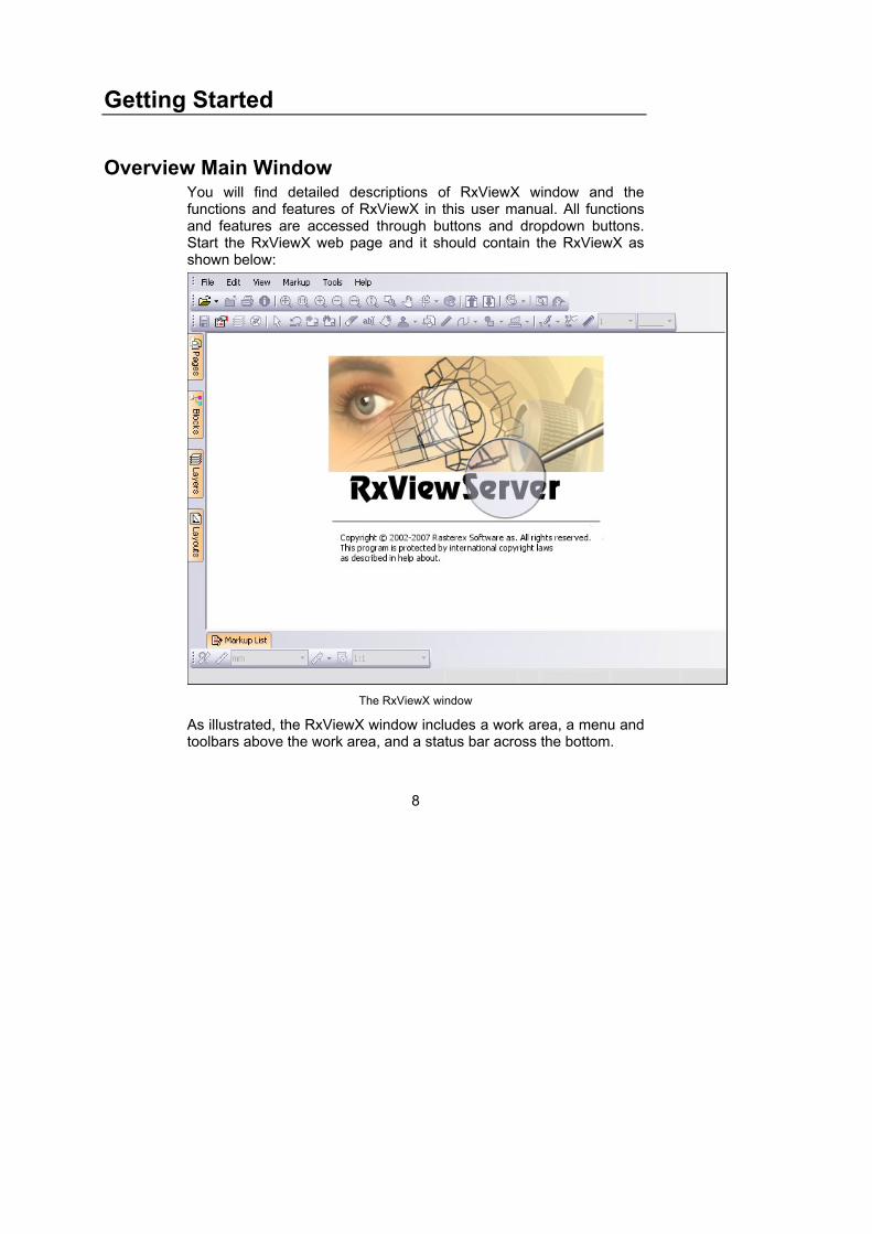
Overview Main Window You will find detailed descriptions of RxViewX window and the functions and features of RxViewX in this user manual. All functions and features are accessed through buttons and dropdown buttons. Start the RxViewX web page and it should contain the RxViewX as shown below:
The RxViewX window
As illustrated, the RxViewX window includes a work area, a menu and toolbars above the work area, and a status bar across the bottom.
9
Menu items
File menu Use the File menu items to open close and print files.
Open - Opens a Windows File Open dialog. Browse, select and open
any file.
Close - Closes the active file.
Print - Opens the Print dialog with multiple options.
Save As – Save the currently open file to your local machine in the
selected format.
Overlay – Create an overlay composite to compare two or more
images.
Edit menu Use the Edit menu to search for, and extract text.
Find - Displays the Find dialog that is used to search for text in a document or drawing.
Find Next – Search for the next occurrence of the search expression specified using the Find function
Copy to Clipboard – Allow you to select a region in the open drawing that will be copied to the clipboard.
Extract Text – Opens the Extract Text dialog.
View menu Use the View menu to zoom, pan, rotate, flip and change the page in multi-page documents. Other functions on the View menu include Measurment, Calibration and file information.
Toolbars – Use this menu item to turn on and off the various RxViewX toolbars.
Zoom – Use this menu item to select from the various zoom functions.
10
- Zoom Window - Zooms in to a particular area of the file and fits it to the view window. Click on the top-left of the area to be viewed and hold down the left mouse button. Drag to the selected area and release the button.
- Zoom All - Zoom All zooms the image to the extents of the window. The function maintains the image’s aspect ratio. If the window has a aspect ratio different to that of the file, the excess area will be given the background color.
- Zoom 1:1 - Zoom 1:1 zooms the image (up or down as appropriate) to its actual size. The function maintains the image’s aspect ratio. Pan sliders will be displayed if required to enable you to view parts of the image that lie outside the boundaries of the window. In the event the file is smaller than the window, excess area will be displayed either to the sides or above and below the file. The excess area will be given the background color selected using the Toggle Background Color menu or button.
- Zoom In - Zoom In zooms in towards the image so the image is enlarged. Each time you initiate the function the image in enlarged one step. The function maintains the image’s aspect ratio. Pan sliders will be displayed if they are required. Click the Zoom Out button to reverse the process.
- Zoom Out - Zoom Out zooms away from the image so the image is reduced in size. The function maintains the image’s aspect ratio. The area between the edges of the image and the window frame will be given the background color Click the Zoom In button to reverse the process.
- Zoom Width - Zoom Width zooms the image to the width of the window. The function maintains the image’s aspect ratio. If the image is too tall to fit in the window after zooming, the vertical pan slider will be displayed to enable you to view those parts of the image that fall outside the window. If the resulting image is smaller than the height of the window, the excess area will be given the background color.
Flip – Use this menu item to create a mirror image of the active file.
You can flip the image around the x and y axis.
11
Multipage – Select to shift multipage documents one page down or one page up.
Rotate – Select to rotate the image anticlockwise through steps of 90° each time this menu item is selected.
Calibrate - Select Calibrate to initiate the calibration function.
Measure - Measure allows measurement on the file. The function measures the length of a line, the angle between two lines, or the area enclosed by multiple lines, inside the viewed file.
File Information - Opens the File Information dialog.
Magnifying Window – Activate the magnifying window that will magnify the portion of the drawing under the cursor.
Birdseye - Opens the Birdseye window that will allow you to see an overview of the drawing when zoomed into a detail in the main window.
Markup menu Menu items on the markup menu are only available if you are running with a ViewServer Pro license.
No Markups – Select to turn the visibility of all comments on/off.
Preferences – Opens the Markup Preferences dialog.
Print Report – Opens the Markup Print Report dialog
Layers – Opens the Markup layers dialog.
Users – Opens the Markup users dialog
Consolidate – Functions for consolidating markup.
- Users and layers – Opens the Consolidate Layers dialog.
- Pick Entities – Enable user to pick markup entities using the mouse.
- Pick Options – Control the behaviour of the Pick entity function.
Export – Save markup to another supported export format.
Save – Save markup to file.
Undo – Undo the last markup draw or edit action.
Push – Set the mouse cursor in push mode to activate markup links and markup notes.
Copy – Copy currently selected markup
12
Paste – Paste copied markup as a new markup entity.
Tools menu Use Tools menu to configure the behaviour of RxViewX and individual formats.
Options – Opens the Options dialog. This dialog has two tabs for General options and format specific options.
File Format Filter Settings – Only availble when running with local RimEngine.
Pen Table – Opens the Pen Table dialog
Search Block Attributes – Opens the dialog for AutoCAD attribute search.
Entity information – Allow you to show information about various elements in a drawing when you click on it using the mouse.
13
Standard Toolbar
The Standard Toolbar Buttons The control toolbar buttons often lead to extensive new dialogs and options. The dialogs are described in detail in the next chapter.
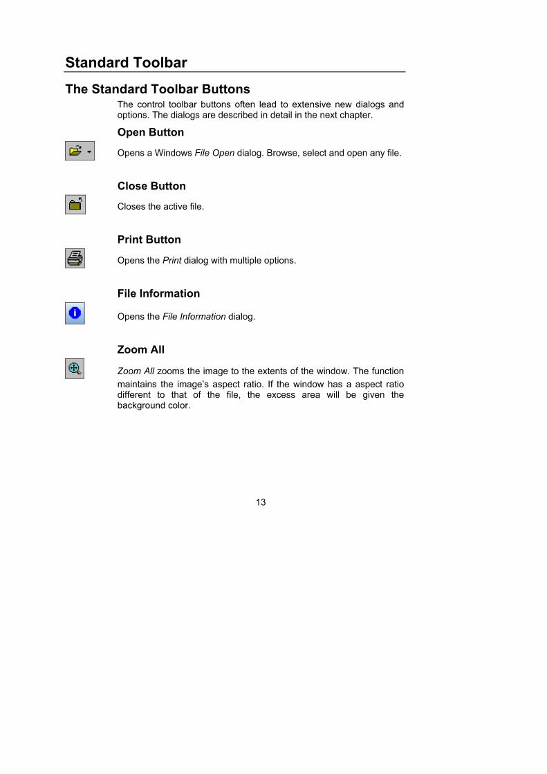
Open Button
Opens a Windows File Open dialog. Browse, select and open any file.
Close Button
Closes the active file.
Print Button
Opens the Print dialog with multiple options.
File Information
Opens the File Information dialog.
Zoom All
Zoom All zooms the image to the extents of the window. The function
maintains the image’s aspect ratio. If the window has a aspect ratio different to that of the file, the excess area will be given the background color.
14
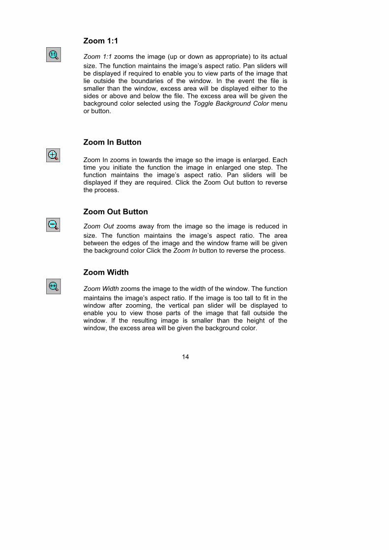
Zoom 1:1
Zoom 1:1 zooms the image (up or down as appropriate) to its actual
size. The function maintains the image’s aspect ratio. Pan sliders will be displayed if required to enable you to view parts of the image that lie outside the boundaries of the window. In the event the file is smaller than the window, excess area will be displayed either to the sides or above and below the file. The excess area will be given the background color selected using the Toggle Background Color menu or button.
Zoom In Button
Zoom In zooms in towards the image so the image is enlarged. Each time you initiate the function the image in enlarged one step. The function maintains the image’s aspect ratio. Pan sliders will be displayed if they are required. Click the Zoom Out button to reverse the process.
Zoom Out Button
Zoom Out zooms away from the image so the image is reduced in
size. The function maintains the image’s aspect ratio. The area between the edges of the image and the window frame will be given the background color Click the Zoom In button to reverse the process.
Zoom Width
Zoom Width zooms the image to the width of the window. The function
maintains the image’s aspect ratio. If the image is too tall to fit in the window after zooming, the vertical pan slider will be displayed to enable you to view those parts of the image that fall outside the window. If the resulting image is smaller than the height of the window, the excess area will be given the background color.
15
Zoom Height
Zoom Height zooms the image to the height of the window. The
function maintains the image’s aspect ratio. If the image is too wide to fit in the window after zooming, the horizontal pan slider will be displayed to enable you to view those parts of the image that fall outside the window. If the resulting image is narrower than the width of the window, the image will be centered horizontally in the window and the excess area will be given the background color.
Zoom Window Button
Zooms in to a particular area of the file and fits it to the view window.
Click on the top-left of the area to be viewed and hold down the left mouse button. Drag to the selected area and release the button.
Pan Hand Button
Pan Hand enables you to view parts of an image that are outside the
window by grabbing the image and moving it. The image will not move if it is less than the window size.
Rotate Button
Rotate button rotates the image anticlockwise through steps of 90° by
clicking the button. You can select between 0, 90, 180 or 270 degree orientation directly from the drop down button.
Toggle Background Color Button
Changes the background color used for vector and monochrome
raster images.
16
Page Down Button
Page down through a multipage file. The button is deactivated if the
file comprises only one page or when the last page is reached. In a spreadsheet file this lists the different sheets. In a vector file this lists the views in the file.
Page Up Button
Page up through a multipage file. The button is deactivated if the file
comprises only one page or when the first page is reached. In a spreadsheet file this lists the different sheets. In a vector file this lists the views in the file.
3D Rotate Button
When operating on a 3D model you can rotate the 3D model in all
directions using the 3D rotation button. The Rotate button enables you to rotate the image about its center point such that you can view the image from any direction. Place the Rotate cursor on the image. Click and hold down the left mouse button. Drag the mouse.
Reset Model Button
Clicking this button will reset the model to its original state. Click the
drop-down arrow beside the button to display a list of 3D functions:
WireFrame
You can display an image as wireframe, i.e. remove the rendering, by clicking the Wireframe button on the 3D toolbar.
17
Remove hidden lines
Check this option to remove lines (e.g. In Wire-frame view) that would normally be hidden by other surfaces.
Enable clipping
Enable clipping will turn on any defined cross section. To see the effects of sectioning as you perform the operation, click the Enable clipping button.
Show Clip Plane
To see the sectioning planes, click the Show Cross-Section Planes button. The planes are displayed in pale gray.
Set Cross-Section
Click the Set Cross-Section button. Place the cursor where you want to start the cut, and click and hold the left mouse button. Drag the cursor to create the desired cutting plane, and then release the mouse button. The part of the image to one side of the cut will disappear.
Section Clipping
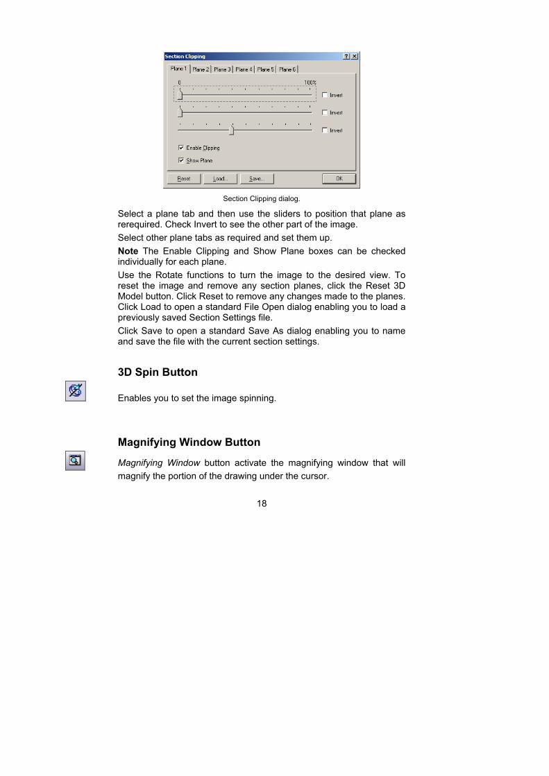
The Section Clipping dialog appears as shown below.
18
Section Clipping dialog.
Select a plane tab and then use the sliders to position that plane as rerequired. Check Invert to see the other part of the image.
Select other plane tabs as required and set them up.
Note The Enable Clipping and Show Plane boxes can be checked individually for each plane.
Use the Rotate functions to turn the image to the desired view. To reset the image and remove any section planes, click the Reset 3D Model button. Click Reset to remove any changes made to the planes. Click Load to open a standard File Open dialog enabling you to load a previously saved Section Settings file.
Click Save to open a standard Save As dialog enabling you to name and save the file with the current section settings.
3D Spin Button
Enables you to set the image spinning.
Magnifying Window Button
Magnifying Window button activate the magnifying window that will
magnify the portion of the drawing under the cursor.
19
Bird’s Eye View Button
Bird’s Eye creates an overview of the file, and allows you to pan
around and select areas to zoom.
The Bird’s Eye View function provides an overview of the file, and allows you to pan around and select areas to zoom.
Overview of an image
Activate the function and a total view of the file contents appears in the Bird's Eye View window. Change the size of the Bird’s Eye window by dragging its borders.
Zooming
Place the cursor inside the Bird's Eye View window and press the right mouse button. Drag the mouse diagonally to create a frame that marks the area you want to zoom into. Release the right mouse button and the selected area zooms to fit the file’s view window.
Panning
The red indicator frame inside the Bird's Eye View window is superimposed over the part of the file currently visible in the file workspace. Place the cursor inside the red frame, click and hold the left mouse button, and drag the cursor until the frame encloses the information you wish to see. As you do so, the view in the work area changes to match the area enclosed in the frame.
20
Measure Toolbar
The Measure Toolbar Buttons The measure toolbar buttons often lead to extensive new dialogs and options. The dialogs are described in detail in the next chapter.
Measure Button
Measure allows measurement on the file. The function measures the
length of a line, the angle between two lines, or the area enclosed by multiple lines, inside the viewed file.
Calibrate
Click the drop-down arrow to the right of the Measure button and
select Calibrate to initiate the calibration function.
Measurement unit
Select the preferred measurement unit for the active measurement system using the measurement unit drop down list on the
Measurement toolbar. The selected measurement
unit will affect results in the measurement dialog as well as any measurement markup elements added. It will also affec the height and width properties displayed in the File properties dialog.
Measurement System
Select the preferred measurement system from this drop down button.
Select between Metric, Imperial, System or Custom. System indicate that you use the internal coordinates inherent in the file format. Custom require that you define a relationship between the internal system measurement values and your custom unit. You need to define this relationship under Tools->Options. Select the tab for the currently active file format.

21
Drawing Scale
Click on this button to open the dialog for available drawing scales.
Drawing scales are saved in a file called rxcalibrate.ini. Values already
defined are avilable from the scale drop down list.
22
RxViewX Dialogs
Print Dialog
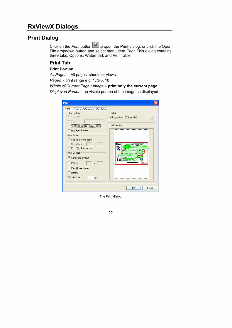
Click on the Print button to open the Print dialog, or click the Open File dropdown button and select menu item Print. This dialog contains three tabs; Options, Watermark and Pen Table.
Print Tab
Print Portion
All Pages – All pages, sheets or views.
Pages - print range e.g. 1, 3-5, 10
Whole of Current Page / Image – print only the current page.
Displayed Portion, the visible portion of the image as displayed.
The Print dialog
23
Print Scale
Scaled to fit the paper - will reduce or expand the image to match the paper size.
Scaled from: to: - enter the scale factor for printing the image. For example, Scaled from 10 to 1 will reduce the image to 1/10 its original size (though this may still require several sheets of paper – refer to option Poster later in this list).
Scale in preview enables you to scale the printout as described in Print Preview options below.
Print Control
Center the printout on the paper is self-explanatory.
Poster prints over multiple sheets. You can set the number of sheets in the No. horizontal and No. vertical fields. The number of sheets used and the position of the image are shown in the preview window. You can scale and move the image to match the selected number of sheets as described in Print Preview options.
Print Monochrome will produce a black and white printer output.
Rotate will rotate the image 90 degrees from the current rotation.
Print Preview
View the printout before you print. Whole of Current Page / Image or Displayed Portion options must be selected. The Print preview represents a true visualization of the image to be printed. It allows you to fit the image to the paper with the required orientation and scaling factor. You can fit the image to the paper both vertically and horizontally by not checking the Maintain aspect ratio.
Position the image on the paper by placing the cursor on the image and dragging The Center the printout option must be unchecked.
Scale the image with or without maintaining the aspect ratio by placing the cursor on the button at the lower right corner of the image and dragging. Whole of Current Page / Image or Displayed Portion options must be selected.
24
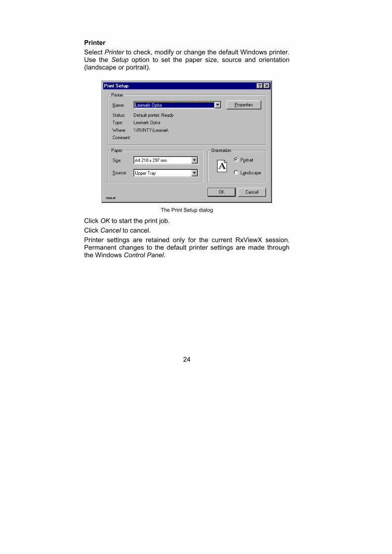
Printer
Select Printer to check, modify or change the default Windows printer. Use the Setup option to set the paper size, source and orientation (landscape or portrait).
The Print Setup dialog
Click OK to start the print job.
Click Cancel to cancel.
Printer settings are retained only for the current RxViewX session. Permanent changes to the default printer settings are made through the Windows Control Panel.
25
Options
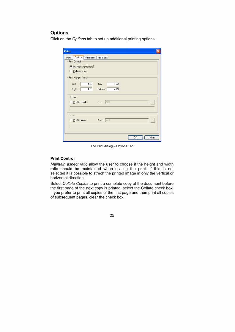
Click on the Options tab to set up additional printing options.
The Print dialog – Options Tab
Print Control
Maintain aspect ratio allow the user to choose if the height and width ratio should be maintained when scaling the print. If this is not selected it is possible to strech the printed image in only the vertical or horizontal direction.
Select Collate Copies to print a complete copy of the document before the first page of the next copy is printed, select the Collate check box. If you prefer to print all copies of the first page and then print all copies of subsequent pages, clear the check box.

26
Print Margins
Fill in the required paper margins in these text boxes.
Header and Footer
Check the Enable Header and Enable Footer check boxes to include header and footer text on the printed document and drawing. Enter the text to use as header and footer in the text boxes for each.
27
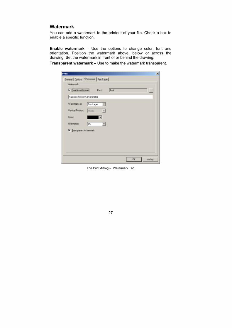
Watermark
You can add a watermark to the printout of your file. Check a box to enable a specific function.
Enable watermark – Use the options to change color, font and orientation. Position the watermark above, below or across the drawing. Set the watermark in front of or behind the drawing.
Transparent watermark – Use to make the watermark transparent.
The Print dialog – Watermark Tab
28
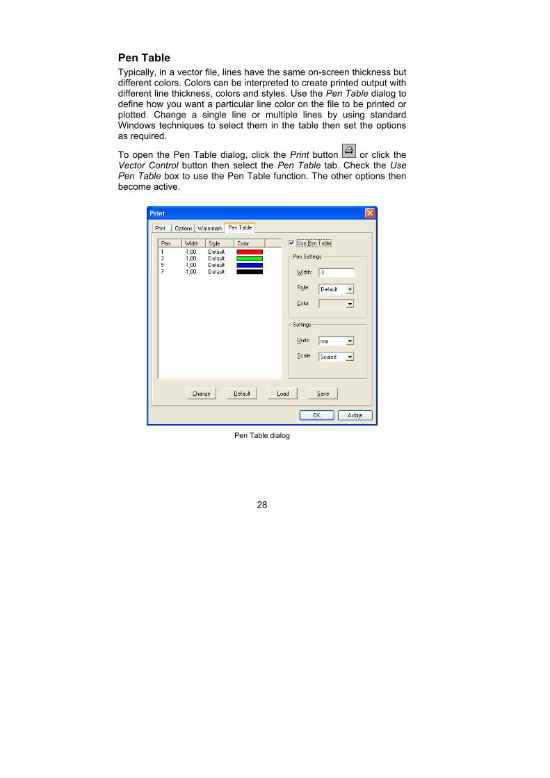
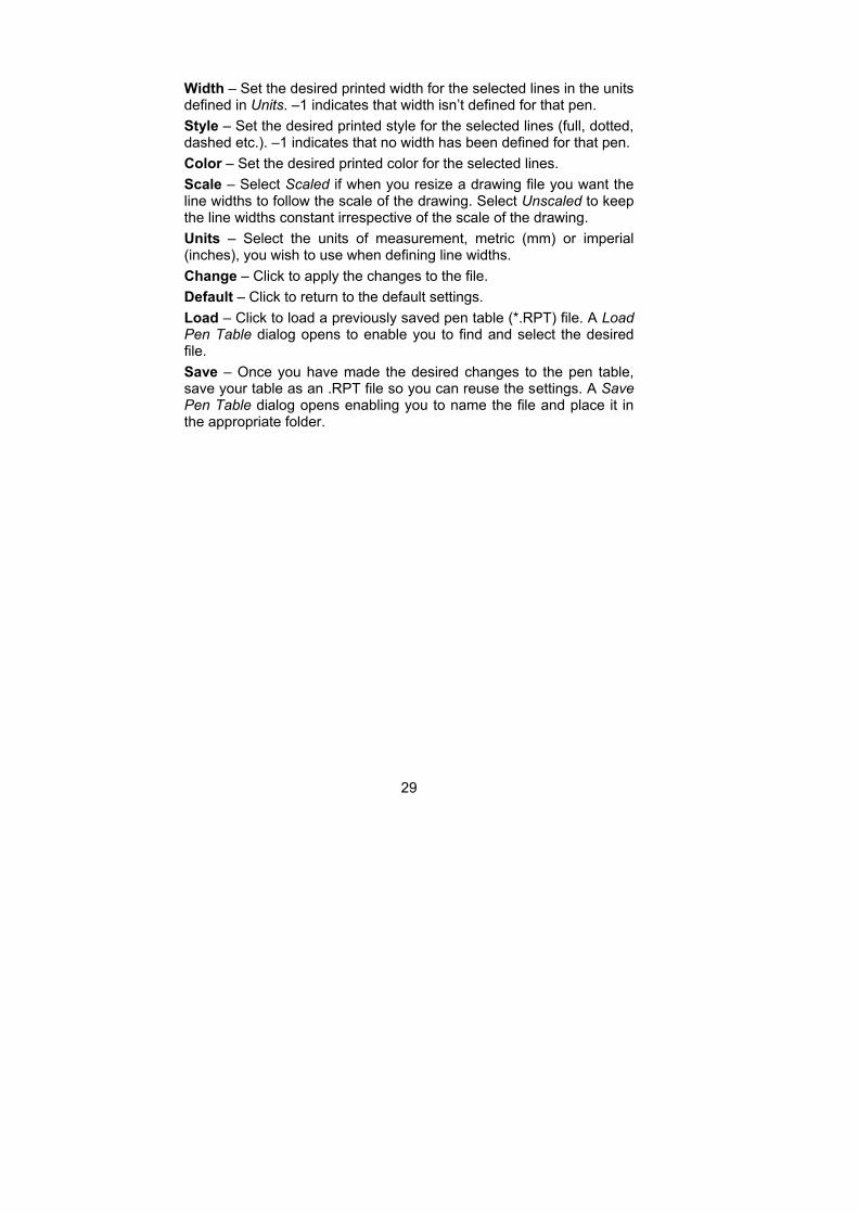
Pen Table
Typically, in a vector file, lines have the same on-screen thickness but different colors. Colors can be interpreted to create printed output with different line thickness, colors and styles. Use the Pen Table dialog to define how you want a particular line color on the file to be printed or plotted. Change a single line or multiple lines by using standard Windows techniques to select them in the table then set the options as required.
To open the Pen Table dialog, click the Print button or click the Vector Control button then select the Pen Table tab. Check the Use Pen Table box to use the Pen Table function. The other options then become active.
Pen Table dialog
29
Width – Set the desired printed width for the selected lines in the units defined in Units. –1 indicates that width isn’t defined for that pen.
Style – Set the desired printed style for the selected lines (full, dotted, dashed etc.). –1 indicates that no width has been defined for that pen.
Color – Set the desired printed color for the selected lines.
Scale – Select Scaled if when you resize a drawing file you want the line widths to follow the scale of the drawing. Select Unscaled to keep the line widths constant irrespective of the scale of the drawing.
Units – Select the units of measurement, metric (mm) or imperial (inches), you wish to use when defining line widths.
Change – Click to apply the changes to the file.
Default – Click to return to the default settings.
Load – Click to load a previously saved pen table (*.RPT) file. A Load Pen Table dialog opens to enable you to find and select the desired file.
Save – Once you have made the desired changes to the pen table, save your table as an .RPT file so you can reuse the settings. A Save Pen Table dialog opens enabling you to name the file and place it in the appropriate folder.
30
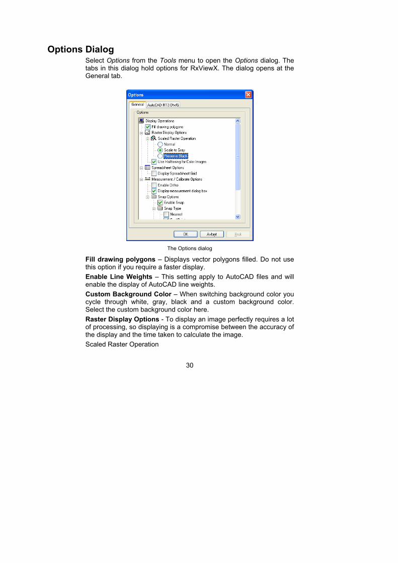
Options Dialog Select Options from the Tools menu to open the Options dialog. The tabs in this dialog hold options for RxViewX. The dialog opens at the General tab.
The Options dialog
Fill drawing polygons – Displays vector polygons filled. Do not use this option if you require a faster display.
Enable Line Weights – This setting apply to AutoCAD files and will enable the display of AutoCAD line weights.
Custom Background Color – When switching background color you cycle through white, gray, black and a custom background color. Select the custom background color here.
Raster Display Options - To display an image perfectly requires a lot of processing, so displaying is a compromise between the accuracy of the display and the time taken to calculate the image.
Scaled Raster Operation
31
Normal – Raster scaling is the fastest method of displaying during zooming. Some black areas may disappear during zooming.
Scale to gray – Scaling is the slowest method of displaying during zooming, but it gives the best display results. If you have problems reading, for example TIF files, use this option to improve clarity.
Preserve black – Scaling is the next fastest display method. Some black areas may disappear during zooming.
Use Halftoning for color images - Halftoning is a tecnique to display color images where the pixels are calculated based on the scaling and the actual pixels to provide a clear display of a color image.
Spreadsheet Options
Display spreadsheet Grid Uncheck this option if you do not want to display and print the grid lines in a spreadsheet.
Measurement / Calibrate Options
Enable Ortho Select this option to lock the measure line to 45 degree increments.
Display measurement dialog box – Select this option to display the measurement result dialog after the measurment is complete.
Snap Options - When performing measurements use the snap function to pull the cursor to nodes. Click the drop-down arrow beside the Snap Type box to select the desired snap type.
Enable Snap – Select this to enable snap.
Snap Marker color – Select the color to use on the snap marker.
Snap type
Nearest – Snaps to the nearest line.
End point – Snaps to the nearest end-point on the nearest line.
Middle point – Snaps to the mid-point of the nearest line.
Center – Snaps to the center of the circle.
Snap tolerance – Use this to set how far from the mouse cursor snap points should be detected.
Printer Settings
Enable transparent raster images when printing – Use this to enable documents that contain transparent raster images to be correctly reproduced on paper. This may be required for some printer drivers.
32
Print Hybrid Files as Raster – Some PDF or HPGL may not print correctly using various PostScript printer drivers. Use this option to ensure that the files are printed correctly.
3D Options
Gradient Background fill – Check this option to enable the backround color to be a gradient when vieweing 3D files.
Application Settings
Delete uploaded files – Check this option to delete uploaded files once they are converted to content format.
Single document mode – Allow only one document to be open at any one time.
Upload external referenced files – RxViewServer will attempt to retrieve reference files from your machine.
Always store markup on exit – RxViewServer will save markup files on exit without giving a warning.
33
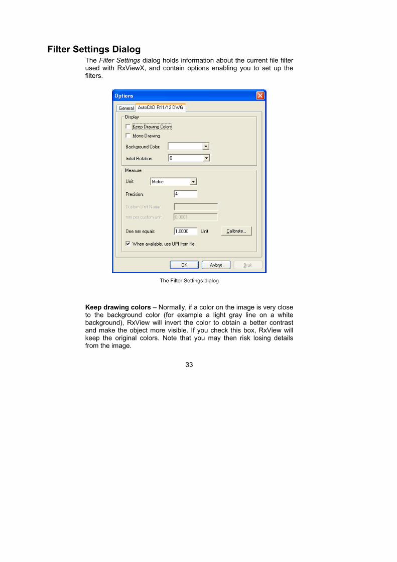
Filter Settings Dialog The Filter Settings dialog holds information about the current file filter used with RxViewX, and contain options enabling you to set up the filters.
The Filter Settings dialog
Keep drawing colors – Normally, if a color on the image is very close to the background color (for example a light gray line on a white background), RxView will invert the color to obtain a better contrast and make the object more visible. If you check this box, RxView will keep the original colors. Note that you may then risk losing details from the image.
34
Mono Drawing – Will display vector files, e.g. DWG, DGN, in monochrome rather than color.
Background color – Sets the default background color to be used for files supported by the selected filter.
Initial Rotation – If a large percentage of the files supported by this filter need to be rotated before opening (for example they may have been scanned at a different angle), you can preset a rotation angle here.
Unit – Set the type of units required for files associated with this filter. Choose between System, Imperial, Metric and User.
System – No units of measurement are specified for this filter, so RxView will use the default units specified by the file.
Imperial – Use imperial units for the filter.
Metric – Use metric units.
User – Define your own units for the filter. Name the units
Precision – Must be input for the selected units. The decimals are shown in the X and Y coordinate fields located in the right end of the status bar when a drawing is loaded.
Custom unit name – If you wish to define your own unit of measurement, give it a name here.
mm per custom unit – Define how large, in mm, you wish your units to be.
One mm equals – Some files have a resolution in dots per inch included in the file.
Depending on the type of units selected, the resolution will be shown in dots per inch, dots per mm or the user-defined unit selected for the filter.
AutoCAD files do not have absolute units of measurement, so for these files you must decide the length a unit is to have. The easiest way to do this is to use Calibrate.
Calibrate allows you to set the scale of a drawing.
When available use UPI from file – Some file types contain UPI (Units per Inch) information. Check this box if you want to use UPI information in your measurements.
35
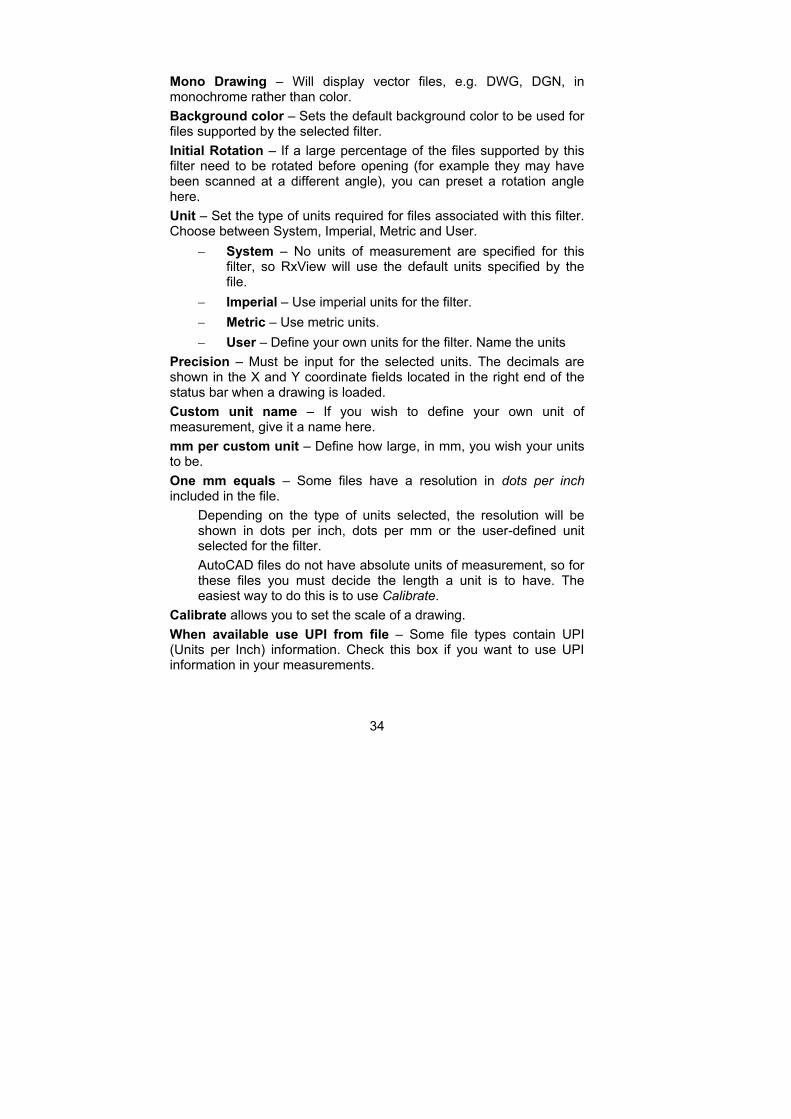
Find Text The Find Text dialog provide the possibility to search for text in the current file.
The Find Text dialog
Find What – Enter the word to search for in this field.
Match Word – Select this to exclude matches that is part of a longer word.
Match Case – Select this to perform a case sensitive search.
Find – Click this button to start the search.
Cancel – Click this button to close the dialog.
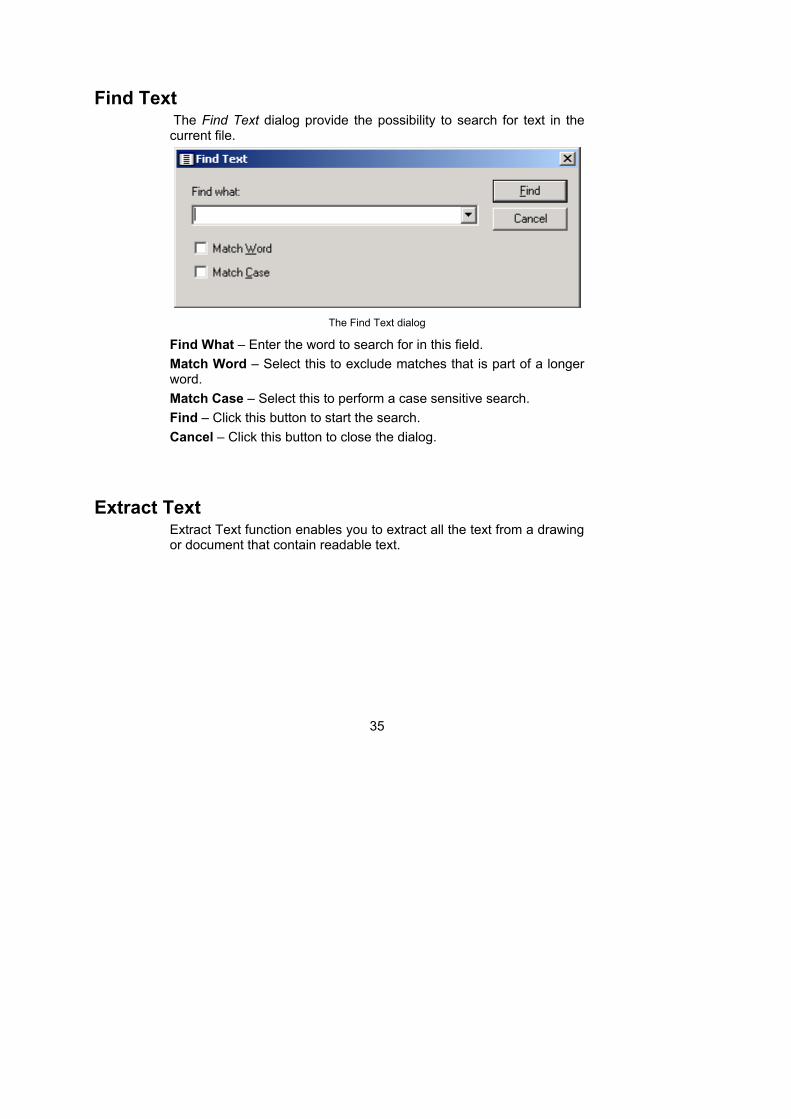
Extract Text Extract Text function enables you to extract all the text from a drawing or document that contain readable text.
36
Text Extraction dialog
Save – Save the text to a text file.
Clipboard – Copies the extracted text to the clipboard.
Extract – Extracts text if any from the current file.
Close – Close the Batch Print dialog.
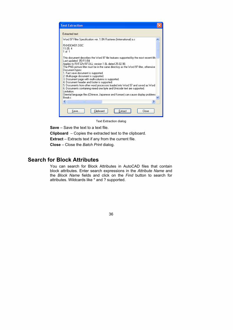
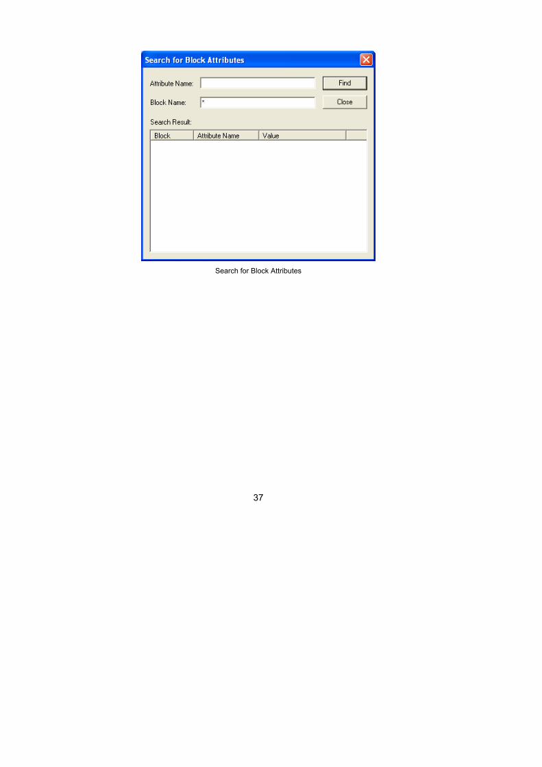
Search for Block Attributes You can search for Block Attributes in AutoCAD files that contain block attributes. Enter search expressions in the Attribute Name and the Block Name fields and click on the Find button to search for attributes. Wildcards like * and ? supported.
37
Search for Block Attributes
38
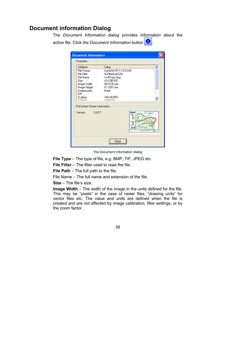
Document information Dialog The Document Information dialog provides information about the
active file. Click the Document Information button .
The Document Information dialog
File Type – The type of file, e.g. BMP, TIF, JPEG etc.
File Filter – The filter used to read the file.
File Path – The full path to the file.
File Name – The full name and extension of the file.
Size – The file’s size.
Image Width – The width of the image in the units defined for the file. This may be “pixels” in the case of raster files, “drawing units” for vector files etc. The value and units are defined when the file is created and are not affected by image calibration, filter settings, or by the zoom factor.

39
Image Height – The height of the image in the units defined for the file. See Image Width above.
Image Depth – For 3D images, the depth of the image in the units defined for the file. See Image Width above.
Compression – The type of file compression used.
DPI – Dots per inch, the resolution of the file.
Scaling – An internal factor for RimEngine relating the screen coordinate system with the file’s internal information.
X-Offset – Information retrieved from file header.
Y-Offset – Information retrieved from file header.
No. of Views – in vector CAD files
No. of Pages – in multipage documents and PowerPoint presentations.
No. of Sheets – in spreadsheets.
40
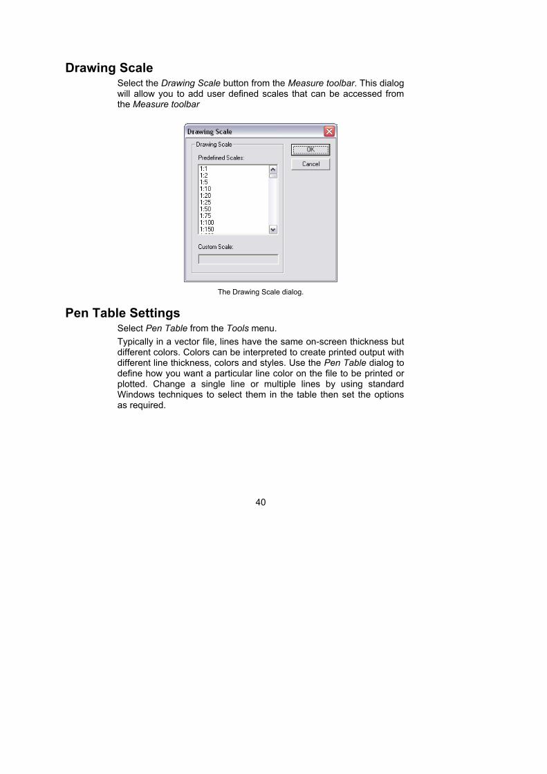
Drawing Scale Select the Drawing Scale button from the Measure toolbar. This dialog will allow you to add user defined scales that can be accessed from the Measure toolbar
The Drawing Scale dialog.
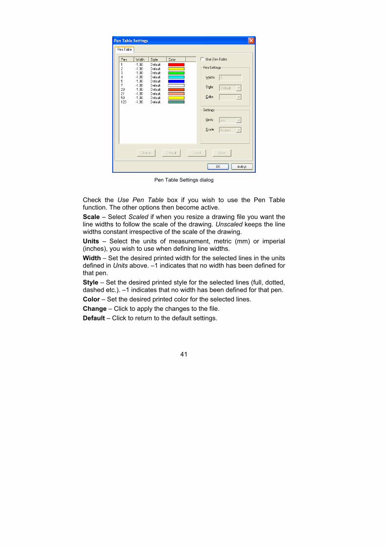
Pen Table Settings Select Pen Table from the Tools menu.
Typically in a vector file, lines have the same on-screen thickness but different colors. Colors can be interpreted to create printed output with different line thickness, colors and styles. Use the Pen Table dialog to define how you want a particular line color on the file to be printed or plotted. Change a single line or multiple lines by using standard Windows techniques to select them in the table then set the options as required.
41
Pen Table Settings dialog
Check the Use Pen Table box if you wish to use the Pen Table function. The other options then become active.
Scale – Select Scaled if when you resize a drawing file you want the line widths to follow the scale of the drawing. Unscaled keeps the line widths constant irrespective of the scale of the drawing.
Units – Select the units of measurement, metric (mm) or imperial (inches), you wish to use when defining line widths.
Width – Set the desired printed width for the selected lines in the units defined in Units above. –1 indicates that no width has been defined for that pen.
Style – Set the desired printed style for the selected lines (full, dotted, dashed etc.). –1 indicates that no width has been defined for that pen.
Color – Set the desired printed color for the selected lines.
Change – Click to apply the changes to the file.
Default – Click to return to the default settings.
42
Load – Click to load a previously saved pen table (*.RPT) file. A Load Pen Table dialog opens to enable you to find and select the desired file.
Save – Once you have made the desired changes to the pen table, save your table as an .RPT file so you can reuse the settings. A Save Pen Table dialog opens enabling you to name the file and place it in the appropriate folder.
OK – Apply the changes and close the dialog.
Cancel – Cancel the changes and close the dialog.
Bird’s Eye View The Bird’s Eye View function provides an overview of the file, and allows you to pan around and select areas to zoom.
Click the Bird’s Eye View button on the View toolbar, or select the View > Bird’s Eye menu item.
Overview of an image
Activate the function and a total view of the file contents appears in the Bird's Eye View window. Change the size of the Bird’s Eye window by dragging its borders.
Zooming
Place the cursor inside the Bird's Eye View window and press the right mouse button. Drag the mouse diagonally to create a frame that marks the area you want to zoom into. Release the right mouse button and the selected area zooms to fit the file’s view window.
Panning
The red indicator frame inside the Bird's Eye View window is superimposed over the part of the file currently visible in the file workspace. Place the cursor inside the red frame, click and hold the left mouse button, and drag the cursor until the frame encloses the information you wish to see. As you do so, the view in the work area changes to match the area enclosed in the frame.
43
The Magnifying Window Click the Magnifying Window button to magnify a part of the active
file and display the enlarged area in a new window.
Click the Magnifying Window button on the View toolbar. Select the View > Magnifying Window menu option.
Set the magnifying scaling factor in the Tools > Options > General tab dialog.
Pages List Bar
The Pages List Bar is one of the workspace panes available in the upper left corner of the workspace. If hidden you can click on the Pages button to display it. Drawings and documents that contain multiple pages can be navigated using this list. A thumbnail for each page is displayed and can be selected to display that particular page in the main workspace window.
Block List Bar
The Block List Bar is one of the workspace panes available in the upper left corner of the workspace. If hidden you can click on the Block button to display it. Within a vector file, vector entities (lines, circles etc.) can be arranged into groups, called blocks, and the blocks can be named. This Workspace Pene provides information about the various blocks of entities and references included in the file. The tree structure in this Pane enables you to toggle each block individually. Apply to CAD and Full versions only.
Layer List Bar
The Layer List Bar is one of the workspace panes available in the upper left corner of the Workspace. If hidden you can click on the Layers button to display it. This Workspace Pane enables you to turn on and off selected layers in a multi-layer file. At the top of the pane some buttons will allow you to control the display of individual layers. Using standard Windows selection techniques, select the layers you wish to toggle.
44
Show Selected Layers – Click this button to turn selected layers on.
Hide Selected Layers – Click this button to turn selected layers off.
Toggle – Click this option to toggle the selected layer to the other
setting (on or off).
Restore Default Settings – Click this option to reset the layers to
their default values (as they were when the file was initially opened).
Note When printing a file, only the displayed layers will be printed. The layer columns can be rearranged, resized and sorted.
Layouts List Bar
The Layouts List Bar is one of the workspace panes available in the upper left corner of the workspace. If hidden you can click on the Layouts button to display it. Drawings that contain multiple Layouts can be navigated using this list. The name of each layout is listed and can be selected to display that particular layout in the main workspace window.

45
Status Bar
The Status Bar across the bottom of the program window displays the following information:
The Progress Pane – indicates the progress of an operation being performed by the system.
The current cursor position in x-y coordinates.
The current units of measurement.
The markup signature and layer for any selected comment.
Information about any vector entity selected with the Entity Information tool.
When Push is active, the selected URL link path.
46
Markup Toolbar
The markup toolbar has 2 extensive dialogs that are described in detail in the next chapter.
Markups are drawn with the thickness of the pen width defined in the Set Line Thickness box at the lower end of the Markup toolbar.
Text characters and numbers are written using Windows fonts and are not affected by the Set Line Thickness settings.
Markup Toolbar Buttons The Markup tools are displayed down the left side of the work area.
Some tools have several options. These tools have a drop-down arrow beside them. Click the arrow to open a list of the options.
Save Button
Click this button to save your markups to file. The markups will be saved to a file with the same name as the markup file and with the extension as specified in the Markup Preferences dialog. The file will be saved in the directory specified in the Markup Preferences dialog.
Markup Preferences
Click this button to open the Markup Preferences dialog. This dialog
box has three tabs; General, File and Advanced.
Layer Control Button
Click this button to open the Markup Layer Control dialog.
47
Enable / Disable Button
Toggles markups display. When markups are disabled, the remaining buttons in the markup toolbar (except the Markup Preferences button) are grayed out.
Edit Button
Click on this button to activate the Markup Edit function. This allows you to select a markup. Markup functions Edit, Move, Size, Rotate, Delete, Zoom, Cut and Copy are described in chapter Markup dialogs.
The commands available for markups vary according to their properties. The cursor changes according to available functionality.
Select the icon and click a markup, the user or commentator name and markup layer show in the status bar.
Undo Button
Undo the last markup made or edited. The button has only one undo
level and is grayed out if there is no operation to undo.
Show next markup
Locate and zoom into the next markup entity. Subsequent use of
Show next markup will cycle through all existing markup entities and start on top with the first markup entity if the last markup entity is the current entity.
Find Markup Text and Entities
Displays the Find Markup Entity dialog. Use this dialog to Search for Markup entities by name or markup text matching a text search criteria.
48
Rubber Button
Click this button to draw markups that hide image information and
other markups. These markups are invisible but can be selected, moved and deleted like visible markups.
Use this tool to draw free-hand lines, as though with a pen, on the active image. Move the curser to the desired start point, click and hold the left mouse button, and move the cursor to draw the line.
Select the pen width in the Set Line Thickness list box at the bottom of the Markup toolbar.
“Rubber” markup color always follows the background color of the file.
Text Button
Click on this button to activate the Markup Text dialog. This is used to
write text directly onto the active file, and is normally used for shorter markups. For longer text markups you are recommended to check the Hide the text in Note envelope option in the Markup Text dialog. A full description of the Markup Text dialog and functions is in chapter Markup Dialogs.
Set the color in the Markup Preferences dialog.
Set the text font size in the Font dialog displayed when you click on the drawing. When working with larger drawings you may need to experiment to find the appropriate settings.
Set the thickness of the markup frame and arrow using the pen width defined in the Set Line Thickness list box at the lower end of the Markup toolbar.

49
Note If you cannot see the text you have written, or it is extremely small, this may be because the Line width and text size option is set to Absolute document units, i.e. relative to the size of the original drawing. For example, text written in a 10 pt. font on an A0 drawing
will be virtually invisible. Click the Markup Preferences button and set the Line width and text size to Current display units, then rewrite the markup. If you wish to delete the original markup, zoom in on the area till you can see the markup, then select and delete it in the normal fashion.
Note When the Line width and text size option is set to Current display units, the resulting markup text size will depend on the amount of zoom applied to the document when the text is written.
Note Button
The Text function is normally used for short comments. For larger comments, use the Note tool. Long markup texts can be stored in "Notes" so they do not cover the work area. To inspect the contents of
a note, select the button and click the note. Editing text and notes
is described in chapter Markup Dialogs.
Stamps
Selecting this button will open a dialog where you can select from a set of pre-defined stamps that you can use in the same way as you would use a rubber stamp on a paper drawing/document. You can include information such as User Signature, date and time in the stamp.
Symbols
Selecting this button will open a dialog where you can select from a set of symbols that you insert as comments into a drawing/document.
To insert a symbol from the list either double click the symbol or select the symbol and click on the Insert button. The symbol will be added to the center of the workspace window.
50
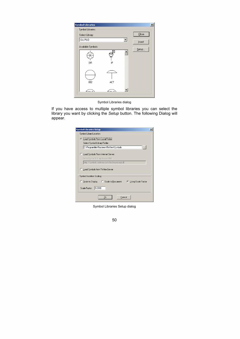
Symbol Libraries dialog
If you have access to multiple symbol libraries you can select the library you want by clicking the Setup button. The following Dialog will appear.
Symbol Libraries Setup dialog
51
This dialog will allow you to either select an existing Symbol Library File or connect to an existing Symbol Library Server.
Symbols are saved as other markups to a markup file associated with the viewed file.
Freehand Pen
Select this button to draw free-hand lines, as though using a pen, on the active image. Move the curser to the desired start point, click and hold the left mouse button, and move the cursor to draw the line.
Lines, Curves and Arrows
Next to this button is a drop down arraow that gives access to choose the type of Line, Curve or Arrow that you want to draw as a comment on the document/drawing.
Set the thickness of lines and arrows using the pen width defined in the Set Line Thickness list box at the lower end of the Markup toolbar.
Set the line color in the Markup Preferences dialog.
Toggle marker mode using the Marker button.
Lines
Select this option to draw straight lines on the active image. Move the cursor to the desired origin and click the left mouse button. Move the cursor to the desired end-point for the line then click the left mouse button again. If you now move the cursor further, another line will be drawn using the previous end-point as its origin. To stop drawing, click the right mouse button.
Orthogonal Mode Hold down the SHIFT key when drawing lines and the lines are snapped and drawn 45 or 90 degrees relative to the screen.
52
Open – Open Polyline that does not connect the first and last point to
make a closed polygon.
Closed – Connect the first and last point to create a closed polygon.
Closed polylines can have different fill types.
Outlined
Select if the polygon is to be outlined (unfilled).
Filled
Select if the rectangle is to be filled.
Edged
Select if the rectangle is to be opaque.
Hatched
Select if the rectangle is to be transparent and hatched.
Curves
Select this option to draw curved lines on the active image.
Open – Open Spline that does not connect the first and last point to
make a closed Spline.
Closed – Connect the first and last point to create a closed spline. Closed splines can have different fill types.
- Outlined
Select if the spline is to be outlined (unfilled).
- Filled
Select if the spline is to be filled.
- Edged
Select if the spline is to be opaque.
- Hatched
Select if the spline is to be transparent and hatched.
Draws an arrow. Click the arrow to open a drop-down menu of the options available.
53
Arrows
Select the type of arrow required.
Double
Select if the arrow is to have two heads.
Filled
Select if the arrow is to be filled.
Rectangles, Circles and Bubbles
Next to this button is a drop down arraow that gives access to choose
the type of Rectangle, Circle or Bubble that you want to draw as a
comment on the document/drawing.
Set the thickness of the outline using the Set Line Thickness list box at the lower end of the Markup toolbar.
Set the line color in the Markup Preferences dialog. Toggle marker mode using the Marker button.
Rectangles
Draws a rectangular or rounded rectangular area. Note that rectangles
can be restricted to squares.
Square Mode Hold down the SHIFT key when drawing rectangles or rounded rectangles and a square or rounded square is drawn.
- Rectangles/Rounded
Select the type of rectangle required. Rounded rectangle gives a rectangle with round corners.
- Outlined
Select if the rectangle is to be open (unfilled).
- Filled
Select if the rectangle is to be filled.
- Edged
Select if the rectangle is to be opaque.
54
- Hatched
Select if the rectangle is to be transparent and hatched.
Ovals / Bubbles
Draws an oval or bubble. Click the arrow to open a drop-down menu of the options available. Note that ovals can be restricted to circles.
Circle Mode Hold down the SHIFT key when drawing circles or bubbles and a circle or symmetrical bubble is drawn.
Ovals/Bubbles
Select the type of shape required; Ovals or bubble shapes.
Outlined
Select if the shape is to be open (unfilled).
Filled
Select if the shape is to be filled.
Edged
Select if the shape is to be opaque.
- Hatched
Select if the shape is to be transparent and hatched.
55
Measurement
Next to this button is a drop down arraow that gives access to choose
the type of measurement tool, line or area, that you want to draw as a
comment on the document/drawing.
Set the thickness of the outline using the Set Line Thickness list box at the lower end of the Markup toolbar.
Set the line color in the Markup Preferences dialog. Toggle marker mode using the Marker button.
Dimension Lines
Dimension lines are double-headed and include the length measurement in the selected units.
You can choose from four different head styles
Lines, Circles, open arrows with lines and closed arrows with lines.
Measurement Area
Select this option to draw a measurement area on the active image.
Draws a measurement area enclosed by polylines. You can select the a fill style for the measurement area.
- Outlined
Select if the measurement area is to indicate the circumference of the area.
- Filled
Select if the measurement area is to indicate the enclosed area.
- Edged
Select if the measurement area is to be opaque.
- Hatched
Select if the shape is to be transparent and hatched.
56
Counting tool
Use the Counting tool to count elements in the drawing. You can select different shapes for the counting tool to differenciate between different elements.
Markup Color
Use this button to set the drawing color used for new markup. You can also use this button to modify the color of existing comments.
Markup Property
The Markup property button will open the markup entity dialog for the currently selected comment.
Marker Button
Click this button to toggle the drawing mode between Normal and
Mark. In Normal mode you draw with opaque colors on the screen, while in Mark mode you draw with transparent colors. This gives the impression of drawing with a marker pen. Mark mode is effective when used on black and white documents such as text documents and mono raster images, but less useful on multi-colored images.
Set Line Thickness
Sets the line thickness or width for drawing lines, rectangles etc. The
thickness is measured in dots.
How to set line thickness
1. Click the Line Thickness list box.
2. The list box drops down.
3. Scroll the list box to the required line thickness.
57
4. Confirm line thickness by clicking on the number.
Or:
Select the box and type the desired line thickness into the box.
Note If the line remains very thin, this may be because the Line width and text size option is set to Absolute document units, i.e. relative to the size of the original drawing. For example, a line drawn on an A0 drawing will be virtually invisible. Select Preferences from the Markup menu and set the Line width and text size to Current display units, then redraw the markup. If you wish to delete the original markup, zoom in on the area till you can see the markup, then select and delete it in the normal fashion.
Set Line Style
Sets the line style for drawing lines, rectangles etc.
How to set line style
Click the Line Style list box.
The list box drops down.
Scroll the list box to the required line style.
Confirm line style by clicking on preferred line style.
58
Markup Dialogs and Editing
Markup Preferences allows control of markup appearance.
User/Layer Control allows control of markup layers and their users or commentators.
Markup Preferences Dialog SelectPreferences from the Markup menu. This dialog holds two tabs; the General tab and the File tab.
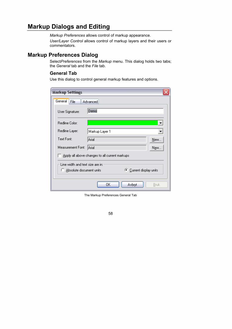
General Tab
Use this dialog to control general markup features and options.
The Markup Preferences General Tab
59
User Signature
The name or alias of the current user. User information is shown in the status bar when a markup is selected.
Redline Color
The markup color used by the current markup layer. All markups on the layer are written in this color. If the color is changed, the color of previous markups on this layer is unchanged but new markups are written in the new current color.
Redline Layer
The markup layer currently selected. All markups are written in this layer. If the layer is changed, the new markups are written in the new current layer. Layer information is shown in the status bar when a markup is selected.
Text Font
The font to be used in text markups. Click the Font button to open a font selection dialog. New text markups are written in the new font and size.
Measurement Font
The font to be used for measurement markups. Click the Font button to open a font selection dialog. New measurement markups are written in the new font and size.
Apply all above changes to all current markups
New markups will always be created using the currently selected user signature, color and layer. However, if existing markups were created in different colors or layers, you can change all markups to the current color, layer and user by checking this item and pressing the Change button. The changes will only be made to the active file.
Note This is a powerful command without an undo function. If
you need to restore the original markup, then close the file and
do NOT save the markup changes which are offered on exiting.
Line width and text size are in
Absolute document units - The line width selected in the Markup Toolbar is relative to the active document's size. A thin markup line on a large document (for example an A0 format drawing) may not be visible on the screen.
60
Current display units - The line width selected in Markup Toolbar is relative to the display size. Typically, a markup line visible on the screen for a large document (for example an A0 format drawing) will be thick when the document is printed or plotted.
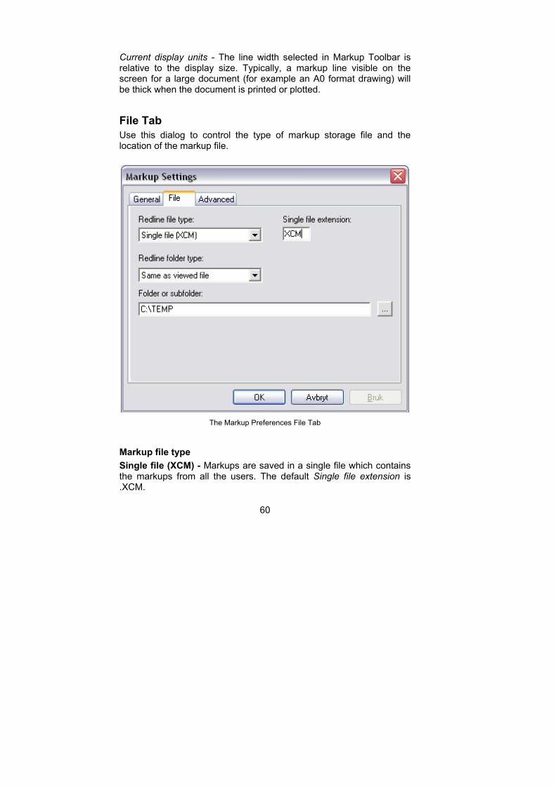
File Tab
Use this dialog to control the type of markup storage file and the location of the markup file.
The Markup Preferences File Tab
Markup file type
Single file (XCM) - Markups are saved in a single file which contains the markups from all the users. The default Single file extension is .XCM.
61
000 - 999 files - Markups are saved in multiple files, one file for each commentator. The files are saved sequentially in the range 000 - 999.
X00 - XZZ files - Markups are saved in multiple files, one file for each commentator. The files are saved sequentially in the range X00 - X9Z.
Single file extension
When you select Single file (XCM) as the Markup file type, the XCM file extension is added as default. However you can save the markup file as any type of file by typing in the appropriate file extension.
Markup folder type
You can select in which folder you wish the markup file to be saved:
Same as viewed file - The markup file is saved in the same folder as the image file to which it is attached.
Subfolder to viewed file - The markup file is saved in a subfolder to the folder in which the image file is located. Type the name of the required subfolder into the Folder or Subfolder field.
Separate markup folder - The markup file is saved in an entirely separate folder to that in which the image file is located. Type the full path and name of the required folder into the Folder or Subfolder field.
Folder or subfolder
If you have selected to save the markup file in a subfolder to the image file folder, or in an entirely separate folder, then browse to the folder or type the path and name of the required markup folder into this data field as described above.
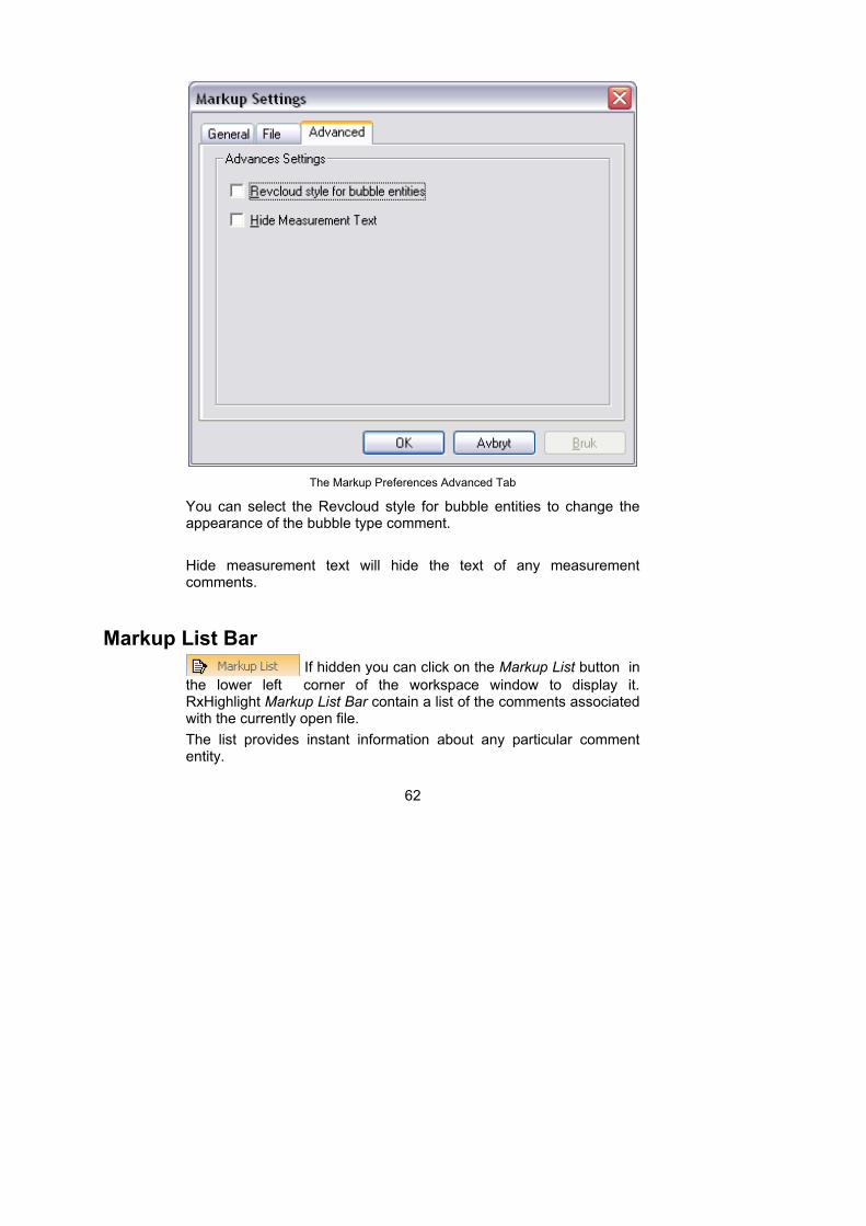
Advanced Tab
Use this to turn on and off advanced redline functions.
62
The Markup Preferences Advanced Tab
You can select the Revcloud style for bubble entities to change the appearance of the bubble type comment.
Hide measurement text will hide the text of any measurement comments.
Markup List Bar
If hidden you can click on the Markup List button in
the lower left corner of the workspace window to display it. RxHighlight Markup List Bar contain a list of the comments associated with the currently open file.
The list provides instant information about any particular comment entity.
63
The comments listed can be sorted by User, Entity, Layer, Date, and Content. Content is any text that may appear in association with a comment entity.
Columns can be turned on and off by right clicking on a column header and select the column that should be displayed from the drop down menu.
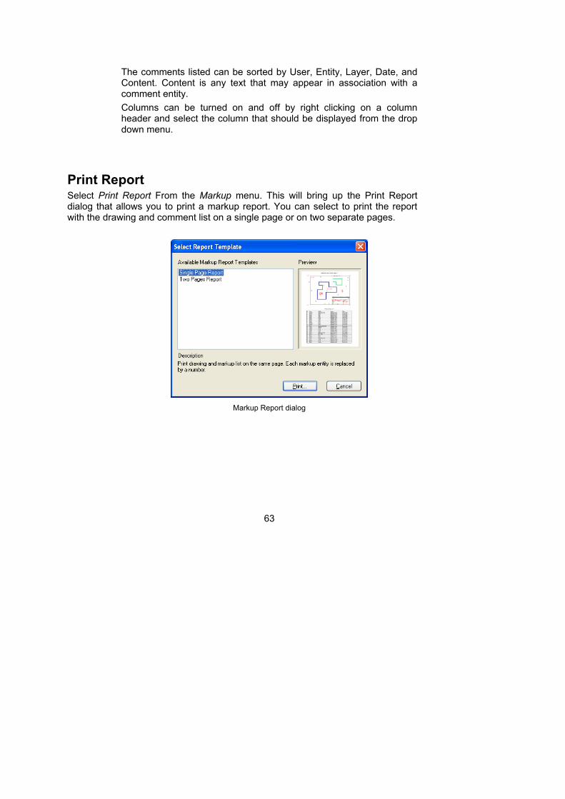
Print Report Select Print Report From the Markup menu. This will bring up the Print Report dialog that allows you to print a markup report. You can select to print the report with the drawing and comment list on a single page or on two separate pages.
Markup Report dialog
64
Markup User and Layer Control Dialogs
Select Users from the Markup menu.
User Control Tab
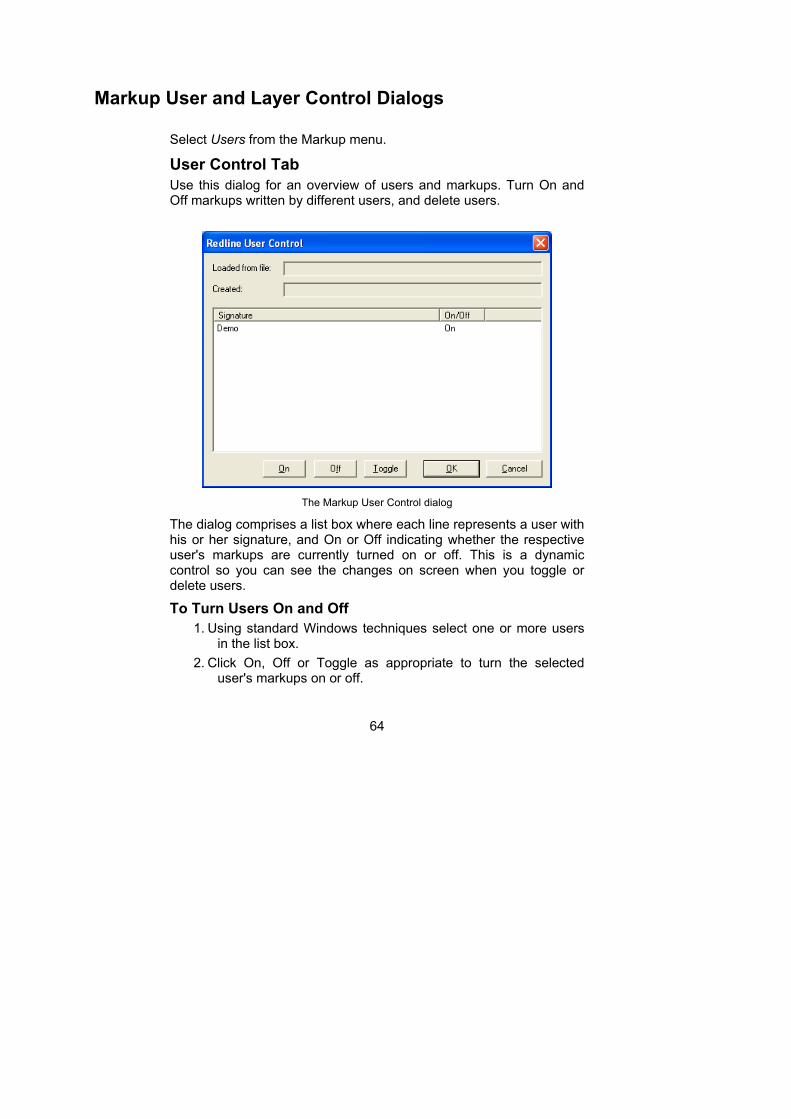
Use this dialog for an overview of users and markups. Turn On and Off markups written by different users, and delete users.
The Markup User Control dialog
The dialog comprises a list box where each line represents a user with his or her signature, and On or Off indicating whether the respective user's markups are currently turned on or off. This is a dynamic control so you can see the changes on screen when you toggle or delete users.
To Turn Users On and Off
1. Using standard Windows techniques select one or more users in the list box.
2. Click On, Off or Toggle as appropriate to turn the selected user's markups on or off.

65
3. Click Close to close the dialog.
To Delete Users
1. Using standard Windows techniques select one or more users in the list box.
2. Click Del to delete the selected users and their markups - this operation removes all the selected markups.
3. Click OK to confirm deletion, or Cancel to restore the deletion.
Warning Deleting other users’ markups is an irreversible
command. If you are in doubt then click Cancel.
Note Your User Profile determines whether you can delete other user's markups. In an organization this will be a restricted command.
66
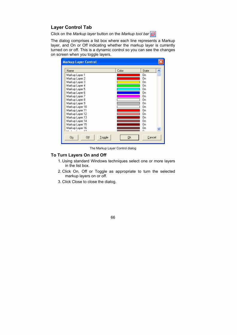
Layer Control Tab
Click on the Markup layer button on the Markup tool bar
The dialog comprises a list box where each line represents a Markup layer, and On or Off indicating whether the markup layer is currently turned on or off. This is a dynamic control so you can see the changes on screen when you toggle layers.
The Markup Layer Control dialog
To Turn Layers On and Off
1. Using standard Windows techniques select one or more layers in the list box.
2. Click On, Off or Toggle as appropriate to turn the selected markup layers on or off.
3. Click Close to close the dialog.
67
Editing Markups
Rules
1. Markups can only be edited by the owner of the markup.
2. The current user must own the markup in order to edit it. The current user is the case-sensitive name shown in the Markup Preferences > General tab > User Signature.
3. To change the current user select Preferences from then Markup menu and write the new user’s name. The user name is case-sensitive. Close the dialog. (Apply to local mode “RxViewX” only.)
4. User information is stored in the markup file. If a user signature is changed you may be asked to save the markup file before exiting the Markup Preferences dialog.
Selecting markups
1. Click the Edit button on the Markup toolbar.
2. Click a markup. The owners name is shown in the status bar. If you are not the owner then you cannot edit the markup. If you own the markup then it will be selected. A selection is enclosed by a black frame with one or more small buttons or handles.
3. Click outside the selection to de-select.
.
Editing markups
The editing controls depend on the type of markup.
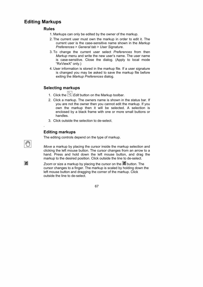
Move a markup by placing the cursor inside the markup selection and clicking the left mouse button. The cursor changes from an arrow to a hand. Press and hold down the left mouse button, and drag the markup to the desired position. Click outside the line to de-select.
Zoom or size a markup by placing the cursor on the button. The cursor changes to a finger. The markup is scaled by holding down the left mouse button and dragging the corner of the markup. Click outside the line to de-select.
68
Rotate a markup by placing the cursor on the button. The cursor changes to a finger. The markup is rotated by holding down the left mouse button and dragging the corner of the markup. Click outside the line to de-select.
Control button on a selected line, arrow or dimension offers Drag and
Scale buttons on the markup. Place the cursor on the button. The cursor changes to a finger. Click to access the grip buttons.
Drag and scale arrow or dimension by placing the cursor on the button, holding down the left mouse button and dragging to move or change the length of a line. Click outside the line to de-select. Add an offset to a dimension line by holding down the left mouse button and drag in the desired direction.
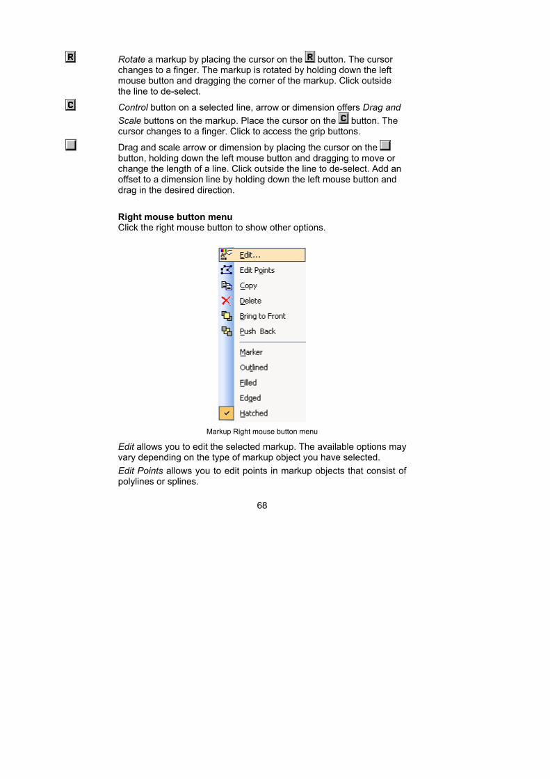
Right mouse button menu Click the right mouse button to show other options.
Markup Right mouse button menu
Edit allows you to edit the selected markup. The available options may vary depending on the type of markup object you have selected.
Edit Points allows you to edit points in markup objects that consist of polylines or splines.

69
Copy create a copy of the selected markup object.
Delete allows you to delete the selected markup.
Bring to Front allows you to move a markup to the front.
Push Back allows you to move a markup to the back.
Marker set the marker mode on for the selected markup object.
Outlined, Filled, Edged and Hatched will change the fill style of the selected markup object.
70
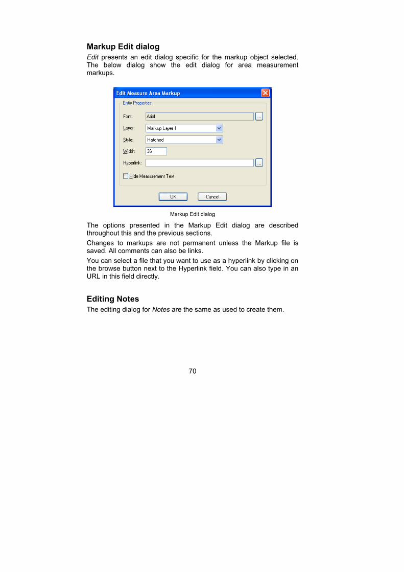
Markup Edit dialog
Edit presents an edit dialog specific for the markup object selected. The below dialog show the edit dialog for area measurement markups.
Markup Edit dialog
The options presented in the Markup Edit dialog are described throughout this and the previous sections.
Changes to markups are not permanent unless the Markup file is saved. All comments can also be links.
You can select a file that you want to use as a hyperlink by clicking on the browse button next to the Hyperlink field. You can also type in an URL in this field directly.
Editing Notes
The editing dialog for Notes are the same as used to create them.
71
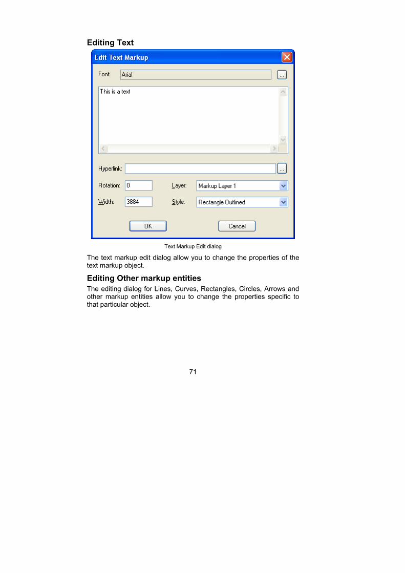
Editing Text
Text Markup Edit dialog
The text markup edit dialog allow you to change the properties of the text markup object.
Editing Other markup entities
The editing dialog for Lines, Curves, Rectangles, Circles, Arrows and other markup entities allow you to change the properties specific to that particular object.
72
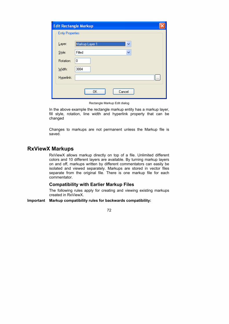
Rectangle Markup Edit dialog
In the above example the rectangle markup entity has a markup layer, fill style, rotation, line width and hyperlink property that can be changed
Changes to markups are not permanent unless the Markup file is saved.
RxViewX Markups RxViewX allows markup directly on top of a file. Unlimited different colors and 10 different layers are available. By turning markup layers on and off, markups written by different commentators can easily be isolated and viewed separately. Markups are stored in vector files separate from the original file. There is one markup file for each commentator.
Compatibility with Earlier Markup Files
The following rules apply for creating and viewing existing markups created in RxViewX.
Important Markup compatibility rules for backwards compatibility:
73
1. RxViewX and RxView R6 with markup can read markup files created by earlier versions of RxHighlight 97/R4 and RxHighX.
2. Markup files created in RxViewX and RxView R6 with markup cannot be read by RxHighlight 97 or RxHighX. All users should therefore upgrade to the same version of the markup software.
3. To read markup files, both 32-bit and 16-bit RxHighlight must have the correct markup file extension type. These are set in the Options > Preferences dialog for 16-bit RxHighlight, and in the Comment > Preferences dialog for 32-bit version.
4. 32-bit RxHighlight can only read markups created in 16-bit RxHighlight.
5. 16-bit RxHighlight cannot read markups created or modified in 32-bit RxHighlight.
6. XCM markup files can only be created and viewed in 32-bit RxHighlight.
7. XLK files, i.e. 16-bit RxHighlight link files, will always be read by 32-bit RxHighlight.
8. Do not rename 16-bit markup files as XCM files. 32-bit RxHighlight will not be able to read them.
Document Linking In RxViewX, links are stored together with markups in the same file(s).
In RxViewX you may link files to each other. In other applications this feature is often called “Hyper-linking”. Linking in RxViewX creates buttons in the viewed file, which are connected with other files. When you click a link button on the viewed file, the corresponding file is loaded. If the file registered in the link is not found in its original location, then the local folder from which the file and Markup is opened is searched.
74
Consolidation Markup entities and comments from multiple users can be transferred to a user with special privileges using the RxViewX consolidation functions. These functions are only available if the following requirements are met.
- Comment files that contain markup entities from more than one user must be opened with the main file.
- The current user must have administrator privileges.
There are several approaches to do markup consolidation.
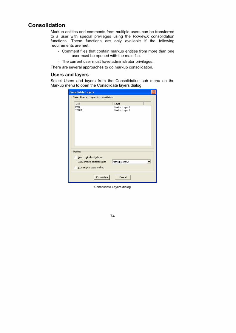
Users and layers
Select Users and layers from the Consolidation sub menu on the Markup menu to open the Consolidate layers dialog.
Consolidate Layers dialog
75
Select the available user signatures from those available in the list and click on the Consolidate button to transfer all the markup entities from the selected users to the current adminstrator user. Some additional options exist that modify the behaviour of the Consolidate function.
Keep original entity layer – Will place the transferred markup entities without changing the layer they are currently on.
Hide original users markup – Will remove the original markup entity from view after consolidation.
Copy entity to selected layer – Will transfer the markup entities from the selected users to a specific markup layer. This require that the Keep original entity layer is turned off.
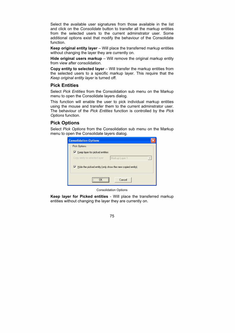
Pick Entities
Select Pick Entities from the Consolidation sub menu on the Markup menu to open the Consolidate layers dialog.
This function will enable the user to pick individual markup entities using the mouse and transfer them to the current adminstrator user. The behaviour of the Pick Entities function is controlled by the Pick Options function.
Pick Options
Select Pick Options from the Consolidation sub menu on the Markup menu to open the Consolidate layers dialog.
Consolidation Options
Keep layer for Picked entities - Will place the transferred markup entities without changing the layer they are currently on.

76
Hide the picked entity - Will remove the original markup entity from view after consolidation.
Copy entity to selected layer – Will transfer the markup entities from the selected users to a specific markup layer. This require that the Keep original entity layer is turned off.
77
Calibration and Measurement
Measuring Distances, Angles and Areas
Activate the Measure function by clicking the Measure button on
the toolbar. Repeat to switch off the function.
Note You may have to calibrate your image first.
The Measurement function enables you to measure the length of a line, the angle between two lines, or the area enclosed by multiple lines, on the active file. The results - Distance, Angle, Area, Accumulated distance - are displayed dynamically in the status bar, and will also be displayed in the Measurement Statistics dialog.
The results are displayed using the units of measurement selected in the Filter Settings > Measure tab for the particular file type.
A Snap function is available to assist with accuracy when measuring to and from particular points on a line.
The results from the Measurement Statistics dialog can be copied to the clipboard then pasted into another application or document.
Snap
Select Options from the Tools menu to open the Options dialog. Scroll down to Snap Options and select Enable Snap to turn the snap mode on. The Snap function improves accuracy when measuring vector drawings. The cursor snaps to defined points (nodes) on the nearest line when the cursor moves within a pre-defined range of the node. The defined nodes are Nearest, End point, Middle point, and Center, and each type of node has a particular cursor shape to indicate the node type.
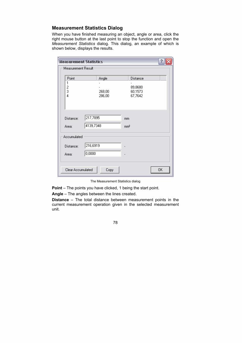
78
Measurement Statistics Dialog
When you have finished measuring an object, angle or area, click the right mouse button at the last point to stop the function and open the Measurement Statistics dialog. This dialog, an example of which is shown below, displays the results.
The Measurement Statistics dialog
Point – The points you have clicked, 1 being the start point.
Angle – The angles between the lines created.
Distance – The total distance between measurement points in the current measurement operation given in the selected measurement unit.
79
Area – The area generated by the current measurement operation, given in the selected measurement unit.
Accumulated distance – The total distance of all the measurement operations since the last time the Clear Accumulated button was pressed.
Accumulated area – The total area generated by all the measurement operations since the last time the Clear Accumulated button was pressed.
Clear Accumulated – Resets the accumulated totals to zero.
Copy – Copies the measurements and accumulated totals to the Windows clipboard so you can paste them into another application as a list. The list has tab delimiters between fields so the text can be pasted and converted to a table in Word or pasted directly into an Excel spreadsheet.
Done – Closes the Measurement Statistics dialog.
Measuring the Length of an Object
1. Zoom in to the image to achieve the appropriate accuracy, activate the Measure function and move the cursor to one end of the object to be measured.
2. Click the left mouse button, move the cursor to the other end of the object and click the right mouse button. An arrow forms behind the cursor as you move it, indicating the start point and current end-point of the measurement line.
The Measurement Statistics dialog is opened and displays the results The results are presented dynamically in the status bar while the measurement function is in progress, and will be deleted from the status bar when a new function is selected.
Measuring the Angle Between Two Lines
1. Zoom in to the image to achieve the appropriate accuracy, activate the Measure function. Move the cursor to one end of the angle to be measured and click the left mouse button.
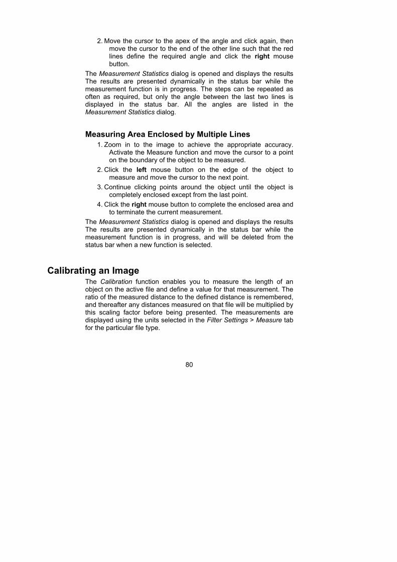
80
2. Move the cursor to the apex of the angle and click again, then move the cursor to the end of the other line such that the red lines define the required angle and click the right mouse button.
The Measurement Statistics dialog is opened and displays the results The results are presented dynamically in the status bar while the measurement function is in progress. The steps can be repeated as often as required, but only the angle between the last two lines is displayed in the status bar. All the angles are listed in the Measurement Statistics dialog.
Measuring Area Enclosed by Multiple Lines
1. Zoom in to the image to achieve the appropriate accuracy. Activate the Measure function and move the cursor to a point on the boundary of the object to be measured.
2. Click the left mouse button on the edge of the object to measure and move the cursor to the next point.
3. Continue clicking points around the object until the object is completely enclosed except from the last point.
4. Click the right mouse button to complete the enclosed area and to terminate the current measurement.
The Measurement Statistics dialog is opened and displays the results The results are presented dynamically in the status bar while the measurement function is in progress, and will be deleted from the status bar when a new function is selected.
Calibrating an Image The Calibration function enables you to measure the length of an object on the active file and define a value for that measurement. The ratio of the measured distance to the defined distance is remembered, and thereafter any distances measured on that file will be multiplied by this scaling factor before being presented. The measurements are displayed using the units selected in the Filter Settings > Measure tab for the particular file type.
81
Note To calibrate a file, the units of measurement for that file must be set to a standard type, i.e. not System. If the Calibrate button is inactive, go to the Measure tab in the Filter Settings dialog and change the unit type.
To activate the Calibrate function, click the dropdown Measure button on the RxViewX toolbar, then select the Calibrate menu item, or Calibrate from the Filter Settings > Measure tab.
Note The Calibrate function switches off automatically once you have completed a calibration operation.
1. Click the drop-down arrow beside the Measure button and select the
Calibrate function.
2. Move the cursor to the object to be measured.
3. Activate the Snap function if required.
4. Click the left mouse button on one end of the object and drag the arrow-headed line to the other end.
i. The length of the connecting line is displayed dynamically in the status bar.
5. Click the right mouse button to stop calibration. A dialog is displayed:
The Measurement Calibration dialog
6. Type into the data field the measurement you wish to use for the selected distance.
7. Check the Set as default for all files of this type box if you wish the scaling function to apply to all files using the same filter.
8. Click OK.
Further measurements on this file will use the new scale.
82
Overlay, Compare
The Overlay feature allows you to overlay one or more files on a background file. Overlay files can be scaled and offset to match a background even if they have different scaling.
The Compare feature allows you to compare two files. Typically, these files would be two revisions of a drawing compared so that the differences can be clearly seen. The differences are highlighted while identical features in the drawings are played down.
Save to raster file allows you to convert and save a drawing file (vector file or raster file) to a raster file format. Typically, CAD drawings can be saved to a non-editable format such as TIFF.
Save to vector file allows you to convert and save a selected drawing file (vector file only) to a vector file format. Typically, CAD drawings can be saved to a compact non-editable standard plot format such as HPGL for distribution.
Overlay Overlay allows you to load several files and display them in the same view window. Many files can overlay each other simultaneously. To overlay files, click the drop-down arrow beside the Open button and select the Overlay File item.
Overlay is a dynamic dialog. Changes to the overlay can be seen on screen as you work. The result is displayed in a new window marked “(Overlay)”. The settings applied to the overlay can be changed and saved. Load the saved overlay settings file (file extension is XWS) and you will re-create the overlay as it was last saved. There is no limit to the number of overlay files you can create.
Note All files to be overlaid or compared must already be loaded before you open the Overlay dialog.
The Document Overlay and Compare dialog shows a list box, see below. The list box shows all the currently loaded files. Only one of these files can be selected as the background image the other files will be overlay files.
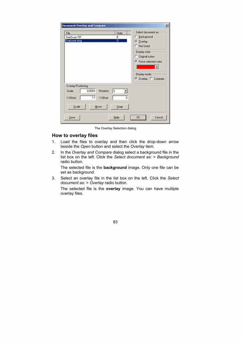
83
The Overlay Selection dialog
How to overlay files
1. Load the files to overlay and then click the drop-down arrow beside the Open button and select the Overlay item.
2. In the Overlay and Compare dialog select a background file in the list box on the left. Click the Select document as: > Background radio button.
The selected file is the background image. Only one file can be set as background.
3. Select an overlay file in the list box on the left. Click the Select document as: > Overlay radio button.
The selected file is the overlay image. You can have multiple overlay files.
84
The Display Color allows setting of colors. Overlay files will normally use the original file colors and the overlay files are displayed transparently on top of the background file as a hybrid. In Compare mode, the overlay file is displayed on top of the background file with an XOR function. This means that any differences between the two drawings are best displayed in a different color. In Compare mode, different Display colors are automatically selected for the active files.
4. The Display Mode offers Overlay or Compare radio buttons. The paragraph above described the difference between Overlay and Compare modes.
5. The Scale entry field allows you to type in an exact scale of the overlay image in relation to the background image.
6. Rotation allows an overlay image to be rotated by selecting the desired angle of rotation, 0, 90, 180 and 270 in the Rotation field.
7. The X-Offset and Y-Offset entry fields allow you to type in the exact position in the background file where the overlay file is to be displayed.
8. Scale allows you to visually scale the overlay file relative to the background file by drawing a measuring line first across the background image and then across a distance on the overlay that should be the same length as measured on the background image.
9. Move allows you to visually move the overlay file relative to the background file by selecting a point first on the overlay image and then select a point on the background that should line up with the selected point on the overlay.
10. Snap forces the overlaid files to fit to the back-ground. This also resets the Overlay Positioning dialog settings and presents a new Scale factor.
Drag the Overlay and Compare dialog box to one side in order to see the result.
11. Save stores the settings of the overlay or hybrid to a file with extension XWS (Rasterex WorkSpace) file.
12. Select OK to confirm the overlay instructions, or Cancel to return to the active file window.
A Rasterex WorkSpace file can have the same name as the background file, but with the extension XWS.
85
An XWS workspace file can be loaded using the drop-down arrow beside the Open button and selecting the item Overlay File.
Move allows you to visually move the overlay file relative to the background file by selecting a point first on the overlay image and then select a point on the background that should line up with the selected point on the overlay.
Note The overlay function is useful for pictures and drawings. You cannot overlay spreadsheets and documents.
Compare Drawing files can be compared to identify changes in a revision process. Typically, these files would be two revisions of a drawing and the comparison shows the differences between them. The differences are highlighted while identical features in the drawings are played down.
Compare is a dynamic dialog. Changes to the comparison can be seen on screen as you work. The result is displayed in a new window marked “(Overlay)”. The settings applied to the comparison files can be saved and loaded. Load the saved compare settings file and you will re-create the compare as it was last saved. There is no limit to the number of compare files you can create.
The process is similar to overlay, but compare files are best viewed in different mono-colors.
Note All files to be overlaid or compared must already be loaded before you open the Overlay dialog.
The Document Overlay and Compare dialog shows a list box, see previous section. The list box shows all the currently loaded files. Only one of these files can be selected as the background image the other files will be overlaid.
How to compare files
13. Load the files to compare and then click the drop-down arrow beside the Open button and select the Overlay item.
86
14. In the Overlay and Compare dialog select a background file in the list box on the left. Click the Select document as: > Background radio button.
The selected file is the background image. Only one file can be set as background.
15. Click the Display Mode > Compare radio button, and the background file is assigned a mono-color.
The selected file is the background image. Only one file can be set as background.
16. Select the file to compare in the list box on the left. Click the Select document as: > Overlay radio button and the compare file is assigned a different mono-color.
The selected file is marked as an overlay image. Even though you can have multiple overlay files, you will not normally use more than 2 files for comparison.
The Display Color allows setting of colors. In Compare mode, the overlay file is displayed on top of the background file with an XOR function. This means that any differences between the two drawings are best displayed in a different color. In Compare mode, different Display Colors are automatically selected for the active files. Colors are assigned even if the drawings are normally displayed as monochrome using the Preferences dialog.
17. The Display Mode is set to Compare radio buttons.
18. The Scale entry field allows you to type in an exact scale of the compare image in relation to the background image. This feature is not normally used in compare files as they will be almost identical.
19. Rotation allows a compare image to be rotated by selecting the desired angle of rotation, 0, 90, 180 and 270 in the Rotation field. This feature is not normally used in compare files as they will be almost identical.
20. The X-Offset and Y-Offset entry fields allow you to type in the exact position in the background file where the compare file is to be displayed. This feature is not normally used in compare files as they will be almost identical.
87
21. Scale allows you to visually scale the overlay file relative to the background file by drawing a measuring line first across the background image and then across a distance on the overlay that should be the same length as measured on the background image.
22. Move allows you to visually move the overlay file relative to the background file by selecting a point first on the overlay image and then select a point on the background that should line up with the selected point on the overlay.
23. Snap to Background forces the overlaid files to fit to the back-ground. This also resets the Overlay Positioning dialog settings and presents a new Scale factor. This feature is not normally used in compare files as they will be almost identical.
Drag the Overlay and Compare dialog box to one side in order to see the result.
24. Save stores the settings of the compare or hybrid to a file with extension XWS (Rasterex WorkSpace) file.
25. Select OK to confirm the overlay instructions, or Cancel to return to the active file window.
A Rasterex WorkSpace file can have the same name as the background file, but with the extension XWS.
An XWS workspace file can be loaded using the drop-down arrow beside the Open button and selecting the item Overlay File.
XWS - Rasterex WorkSpace files Rasterex WorkSpace files contain the file references and settings for creating Overlay or Compare images.
RxViewX can use older versions of XWS files created with RxHighlight R4 and RxHighlight 97.
XWS files created in RxViewX R6 and RxView R6 with markup cannot be read by RxHighlight 97 or RxHighX. All users should therefore upgrade to the same version of the markup software.
You can have many Workspace files comparing different file revisions or overlay scenarios.

88
Workspace files can be loaded, edited and re-saved with new file configurations and settings.
If the participating files registered in the Rasterex WorkSpace file are not found ion their original locations, then the local folder from which the Rasterex WorkSpace file is opened is searched.
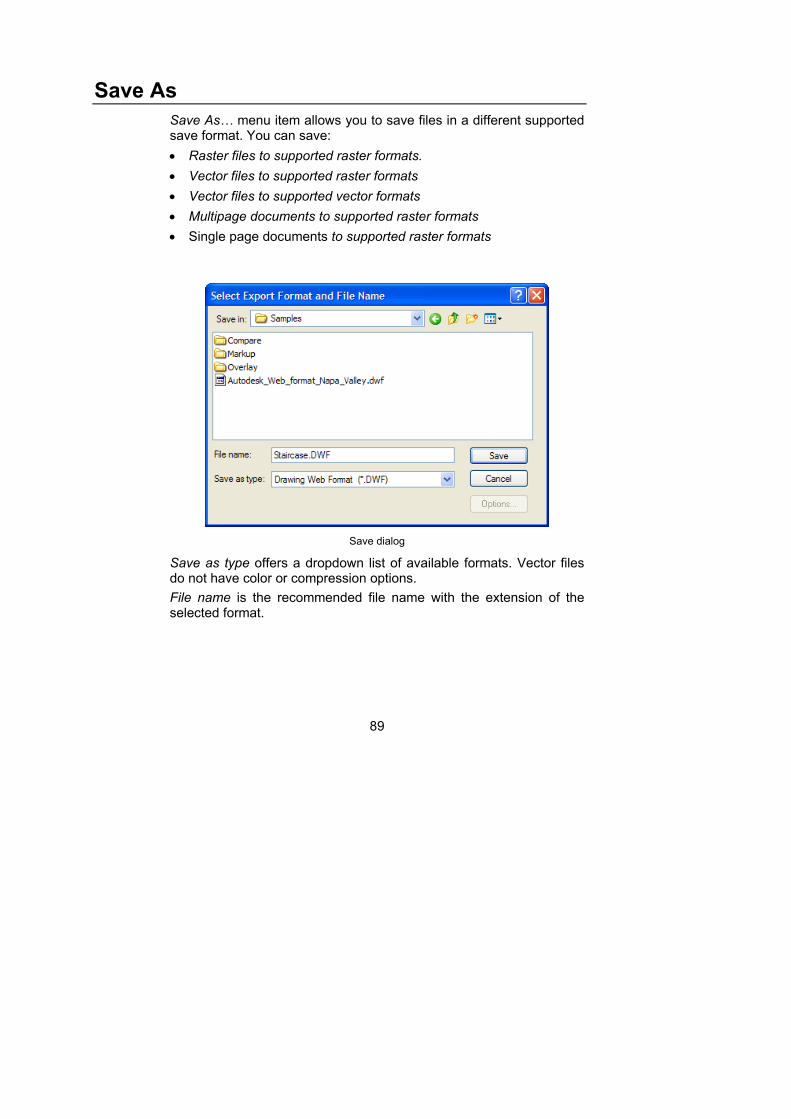
89
Save As
Save As… menu item allows you to save files in a different supported save format. You can save:
Raster files to supported raster formats.
Vector files to supported raster formats
Vector files to supported vector formats
Multipage documents to supported raster formats
Single page documents to supported raster formats
Save dialog
Save as type offers a dropdown list of available formats. Vector files do not have color or compression options.
File name is the recommended file name with the extension of the selected format.
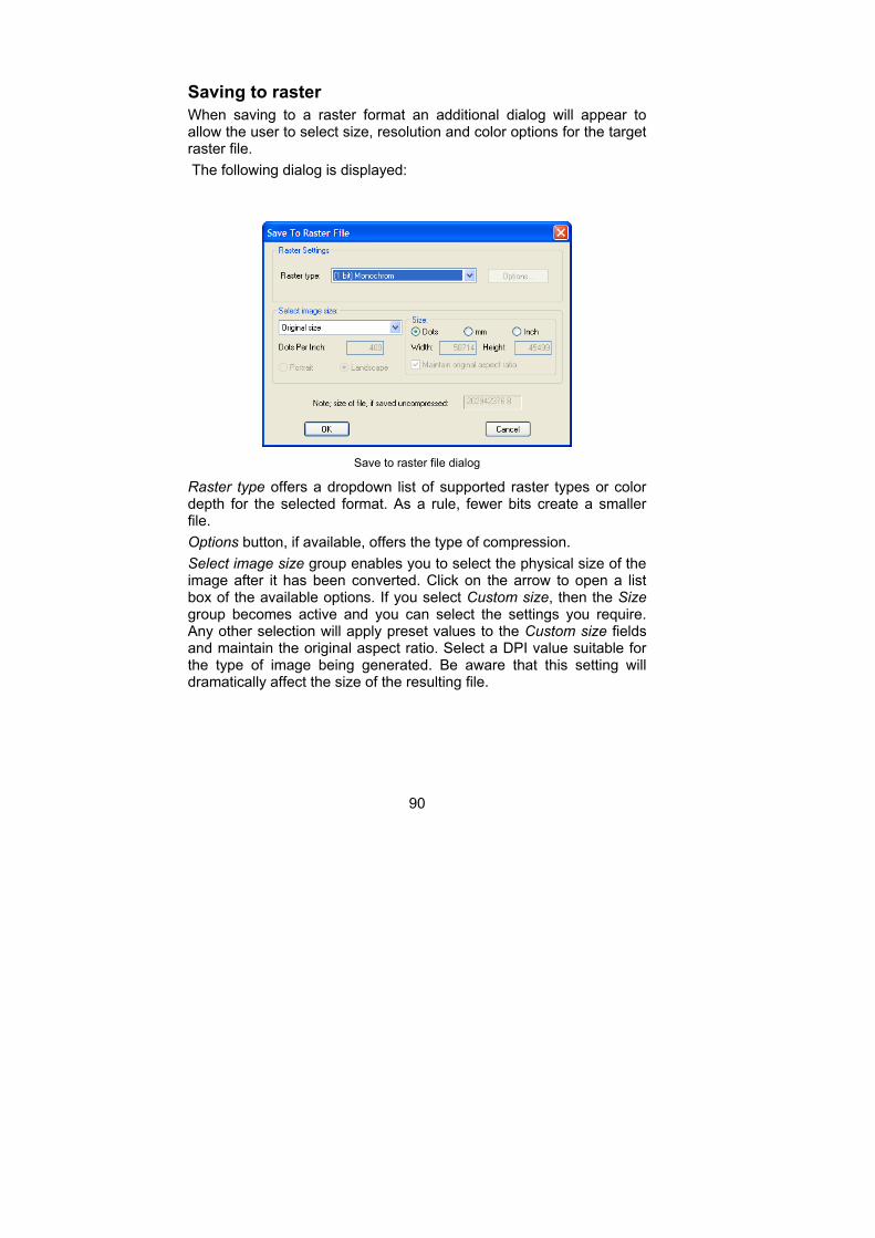
90
Saving to raster
When saving to a raster format an additional dialog will appear to allow the user to select size, resolution and color options for the target raster file.
The following dialog is displayed:
Save to raster file dialog
Raster type offers a dropdown list of supported raster types or color depth for the selected format. As a rule, fewer bits create a smaller file.
Options button, if available, offers the type of compression.
Select image size group enables you to select the physical size of the image after it has been converted. Click on the arrow to open a list box of the available options. If you select Custom size, then the Size group becomes active and you can select the settings you require. Any other selection will apply preset values to the Custom size fields and maintain the original aspect ratio. Select a DPI value suitable for the type of image being generated. Be aware that this setting will dramatically affect the size of the resulting file.

91
Size of file, if saved uncompressed indicates the size of the file that will result from converting the current file using the selected settings and WITHOUT compression. You can generate extremely large files if you create settings that are too large. Always check this field before clicking OK.
Cancel returns to the Select Export Format and File Name dialog.
OK complete the file save operation.