Embed Size (px)
Citation preview
YA-R6F YA-U20F
YA-R5F
S E R I E S
New Generation Robots
S-axis
L-axis
E-axis
U-axis
R-axis
B-axis
T-axis
S-axis
L-axis
E-axis
U-axis
R-axis
B-axis
T-axis
R-axis
B-axis
T-axis
R-axis
B-axis
T-axis
Range ofMotion
MaximumSpeed
Number of axes
Vertical reach
Horizontal reach
Repeatability*1
Payload
AllowableInertia(GD2/4)
AllowableMoment
Mass
Power Requirements*2
*1: Conforms to JIS B 8432. *2: Varies in accordance with applications and motion patterns. *3: When a load is more than 1 kg, the motion range will be smaller. Use the robot within the recommended motion range.
YA-U5F YA-U10F
7
10 kg
1203 mm
720 mm
±0.1 mm
-180° to +180°
-110° to +110°
-170° to +170°
-135° to +135°
-180° to +180°
-110° to +110°
-180° to +180°
170°/s
170°/s
170°/s
170°/s
200°/s
200°/s
400°/s
31.4 N.m
31.4 N.m
19.6 N.m
1.0 kg.m2
1.0 kg.m2
0.4 kg.m2
60 kg
1.0 kVA
7
5 kg
1007 mm
559 mm
±0.06 mm
-180° to +180°
-110° to +110°
-170° to +170°
-90° to +115°
-180° to +180°
-110° to +110°
-180° to +180°
200°/s
200°/s
200°/s
200°/s
200°/s
230°/s
350°/s
14.7 N.m
14.7 N.m
7.35 N.m
0.45 kg.m2
0.45 kg.m2
0.11 kg.m2
30 kg
1.0 kVA
YA-U20F
7
20 kg
1498 mm
910 mm
±0.1 mm
-180° to +180°
-110° to +110°
-170° to +170°
-130° to +130°
-180° to +180°
-110° to +110°
-180° to +180°
130°/s
130°/s
170°/s
170°/s
200°/s
200°/s
400°/s
58.8 N.m
58.8 N.m
29.4 N.m
4.0 kg.m2
4.0 kg.m2
2.0 kg.m2
120 kg
1.5 kVA
YA-RJ
6
1 kg (max. 2 kg*3)
909 mm
545 mm
±0.03 mm
-160° to +160°
-90° to +110°
-
-290° to +105°
-180° to +180°
-130° to +130°
-360° to +360°
160° /s
130° /s
-
200° /s
300° /s
400° /s
500° /s
3.33 N.m
3.33 N.m
0.98 N.m
0.058 kg.m2
0.058 kg.m2
0.005 kg.m2
15 kg
0.5 kVA
YA-R3F
6
3 kg
804 mm
532 mm
±0.03 mm
-160° to +160°
-85° to +90°
-
-105° to +260°
-170° to +170°
-120° to +120°
-360° to +360°
200° /s
150° /s
-
190° /s
300° /s
300° /s
420° /s
5.39 N.m
5.39 N.m
2.94 N.m
0.1 kg.m2
0.1 kg.m2
0.03 kg.m2
27 kg
0.5 kVA
YA-R5F
6
5 kg
1193 mm
706 mm
±0.02 mm
-170° to +170°
-65° to +150°
-
-136° to +255°
-190° to +190°
-135° to +135°
-360° to +360°
376° /s
350° /s
-
400° /s
450° /s
450° /s
720° /s
12 N.m
12 N.m
7 N.m
0.30 kg.m2
0.30 kg.m2
0.1 kg.m2
27 kg
1.0 kVA
YA-R5LF
6
5 kg
1560 mm
895 mm
±0.03 mm
-170° to +170°
-65° to +150°
-
-138° to +255°
-190° to +190°
-135° to +135°
-360° to +360°
270° /s
280° /s
-
300° /s
450° /s
450° /s
720° /s
12 N.m
12 N.m
7 N.m
0.30 kg.m2
0.30 kg.m2
0.1 kg.m2
29 kg
1.0 kVA
YA-R6F
6
6 kg
2486 mm
1422 mm
±0.08 mm
-170° to +170°
-90° to +155°
-
-175° to +250°
-180° to +180°
-45° to +225°
-360° to +360°
220° /s
200° /s
-
220° /s
410° /s
410° /s
610° /s
11.8 N.m
9.8 N.m
5.9 N.m
0.27 kg.m2
0.27 kg.m2
0.06 kg.m2
130 kg
1.0 kVA
7-axis6-axisAssembly / PlacementHandling (general)Applications
YA series Manipulator Specifications
(turning)
(lower Arm)
(elbow twist)
(upper arm)
(wrist roll)
(wrist pich/yaw)
(wrist twist)
(turning)
(lower Arm)
(elbow twist)
(upper arm)
(wrist roll)
(wrist pich/yaw)
(wrist twist)
(wrist roll)
(wrist pich/yaw)
(wrist twist)
(wrist roll)
(wrist pich/yaw)
(wrist twist)
201509-AE
IM Operations
http://global.yamaha-motor.com/business/robot/URL E-mail Specifications and appearance are subject to change without prior notice.
882 Soude, Naka-ku, Hamamatsu, Shizuoka 435-0054, JapanTel 81-53-460-6103 Fax 81-53-460-6811
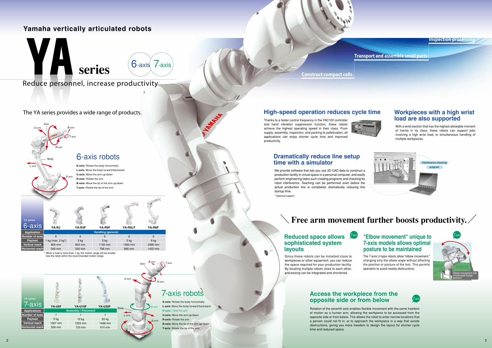
High-speed operation reduces cycle timeThanks to a faster control frequency in the YAC100 controller and hand vibration suppression function, these robots achieve the highest operating speed in their class. From supply, assembly, inspection, and packing to palletization, all applications can enjoy shorter cycle time and improved productivity.
With a wrist section that has the highest allowable moment of inertia in its class, these robots can support jobs involving a high wrist load, or simultaneous handling of multiple workpieces.
We provide software that lets you use 3D CAD data to construct a production facility in virtual space in a personal computer, and easily perform engineering tasks such creating programs and checking for robot interference. Teaching can be performed even before the actual production line is completed, dramatically reducing line startup time.* Optional support
Yamaha vertically articulated robots
series 6-axis 7-axis
Reduce personnel, increase productivity
Since these robots can be installed close to workpieces or other equipment, you can reduce the space required for your production facility. By locating multiple robots close to each other, processing can be integrated and shortened.
7-axis
The 7-axis U-type robots allow "elbow movement," changing only the elbow angle without affecting the position or posture of the tool. This permits operation to avoid nearby obstructions.
7-axis
6-axis robotsS-axis: Rotate the body horizontally
L-axis: Move the body forward/backward
U-axis: Move the arm up/down
R-axis: Rotate the arm
B-axis: Move the tip of the arm up/down
T-axis: Rotate the tip of the arm
7-axis robotsS-axis: Rotate the body horizontally
L-axis: Move the body forward/backward
E-axis: Twist the arm
U-axis: Move the arm up/down
R-axis: Rotate the arm
B-axis: Move the tip of the arm up/down
T-axis: Rotate the tip of the arm
Rotation of the seventh axis enables flexible movement with the same freedom of motion as a human arm, allowing the workpiece to be accessed from the opposite side or from below. This allows the robot to enter narrow locations that a person could not fit in, or to approach the workpiece in a way that avoids obstructions, giving you more freedom to design the layout for shorter cycle time and reduced space.
7-axis
Interference checking
program
Construct compact cells
Transport and assemble small parts
Inspection processing
6-axis YA-R6FYA-R3F YA-R5F YA-R5LFYA-RJ
Handling (general)Application
6 kg
2486 mm
1422 mm
5 kg
1560 mm
895 mm
5 kg
1193 mm
706 mm
3 kg
804 mm
532 mm
1 kg (max. 2 kg*)
909 mm
545 mm
66666
* When a load is more than 1 kg, the motion range will be smaller. Use the robot within the recommended motion range.
Number of axesPayload
Vertical reachHorizontal reach
YA series
7 7
10 kg
1203 mm
720 mm
5 kg
1007 mm
559 mm
7
20 kg
1498 mm
910 mm
YA-U5F YA-U10F YA-U20FAssembly / PlacementApplications
7-axisYA series
Number of axesPayload
Vertical reachHorizontal reach
Free arm movement further boosts productivity.
The YA series provides a wide range of products.
U-axisR-axis
L-axis
E-axis
T-axisB-axis
S-axis
Arm
Body
U-axis
R-axis
S-axis
L-axis
T-axis
B-axis
Arm
Body
32
Workpieces with a high wrist load are also supported
Dramatically reduce line setup time with a simulator
Reduced space allows sophisticated system layouts
"Elbow movement" unique to 7-axis models allows optimal posture to be maintained
Elbow movement with unchanged flange position
Access the workpiece from the opposite side or from below
5.39 N.m
5.39 N.m
2.94 N.m
0.1 kg.m2
0.1 kg.m2
0.03 kg.m2
27 kg
0˚C to +40˚C
20 to 80%RH (non-condensing)
4.9 m/s2 or less
0.5 kVA
YA-R3F
Basic specifications
YA-R3F
YA-R3F
6 (Vertically articulated)
3 kg
±0.03 mm
-160° to +160°
-85° to +90°
-105° to +260°
-170° to +170°
-120° to +120°
-360° to +360°
3.49 rad/s, 200°/s
2.62 rad/s, 150°/s
3.32 rad/s, 190°/s
5.24 rad/s, 300°/s
5.24 rad/s, 300°/s
7.33 rad/s, 420°/s
Allowable
Moment
Allowable
Inertia
(GD2/4)
Ambient
Conditions
S -axis (turning)
L -axis (lower Arm)
U -axis (upper arm)
R -axis (wrist roll)
B -axis (wrist pich/yaw)
T -axis (wrist twist)
S -axis (turning)
L -axis (lower Arm)
U -axis (upper arm)
R -axis (wrist roll)
B -axis (wrist pich/yaw)
T -axis (wrist twist)
R -axis (wrist roll)
B -axis (wrist pich/yaw)
T -axis (wrist twist)
R -axis (wrist roll)
B -axis (wrist pich/yaw)
T -axis (wrist twist)
Temperature
Humidity
Vibration
Others
Range of
Motion
Maximum
Speed
Model
Controlled Axis
Payload
Repeatability*1
Power Requirements*2
Mass
(Note 2)(Note 1)
P-Point
193
47
381
133
74
389
337
57
55°
532
583
822
900
270188229372
7930
531 40
189
180
21
219
158
2040
85°
260°
276
659
42
0
290
260 474
B
T
R
L
R104
80
R188
R532
3718
S
View A View B
View C
4×φ9 (Mounting Holes)
φ6H7 (Reference Hole)
Connector for internal user I/O wiring harness Matching connector provided by users.
5050±0.1
88±0.1155
50
145
150
170
88±0
.1
4 Air inletsTapped hole M5 (4 places)with pipe plug
45°
φ20H
6
φ40h
6
4×M5×P0.8 Depth: 9
3×M8×P1.25Depth: 16
φ5H7 Depth: 7
φ31.5
5 (fitting depth)
View D
Connector for internal user I/O wiring harness Matching connector provided by users.
4 Air outletsTapped hole M5(4 places)with pipe plug
B
C
A
D
160°
160°
Note 1: Motion range of point P when the S-axis is between -40° to +40°.Note 2: Motion range of point P when the S-axis is between -125° to -160° or +125° to +160°.
150
170
90°
78±0
.1
105°
5 (fitting depth)
UU
YA-RJ
Basic specificationsYA-RJ
6 (Vertically articulated)
1 kg (max. 2 kg*1)
±0.03 mm
-160° to +160°
-90° to +110°
-290° to +105°
-180° to +180°
-130° to +130°
-360° to +360°
L-axis, U-axis
2.79 rad/s, 160°/s
2.27 rad/s, 130°/s
3.49 rad/s, 200°/s
5.23 rad/s, 300°/s
6.98 rad/s, 400°/s
8.72 rad/s, 500°/s
Allowable
Moment
Allowable
Inertia
(GD2/4)
Ambient
Conditions
3.33 N.m
3.33 N.m
0.98 N.m
0.058 kg.m2
0.058 kg.m2
0.005 kg.m2
15 kg
During operation: 0 to +40˚C,
During storage: -10 to +60˚C
90% max. (non-condensing)
4.9 m/s2 or less
Floor or ceiling
0.5 kVA
• Free from corrosive gasses or liquids, or explosive gasses
• Free from exposure to water, oil, or dust• Free from excessive electrical noise (plasma)
• Free from corrosive gasses or liquids, or explosive gasses
• Free from exposure to water, oil, or dust• Free from excessive electrical noise (plasma)
S -axis (turning)
L -axis (lower Arm)
U -axis (upper arm)
R -axis (wrist roll)
B -axis (wrist pich/yaw)
T -axis (wrist twist)
S -axis (turning)
L -axis (lower Arm)
U -axis (upper arm)
R -axis (wrist roll)
B -axis (wrist pich/yaw)
T -axis (wrist twist)
R -axis (wrist roll)
B -axis (wrist pich/yaw)
T -axis (wrist twist)
R -axis (wrist roll)
B -axis (wrist pich/yaw)
T -axis (wrist twist)
Ambient Temperature
Relative Humidity
Vibration Acceleration
Mounting
Others
Range of
Motion
Maximum
Speed
Model
Controlled Axis
Payload
Repeatability*2
Power Requirements*4
Mass
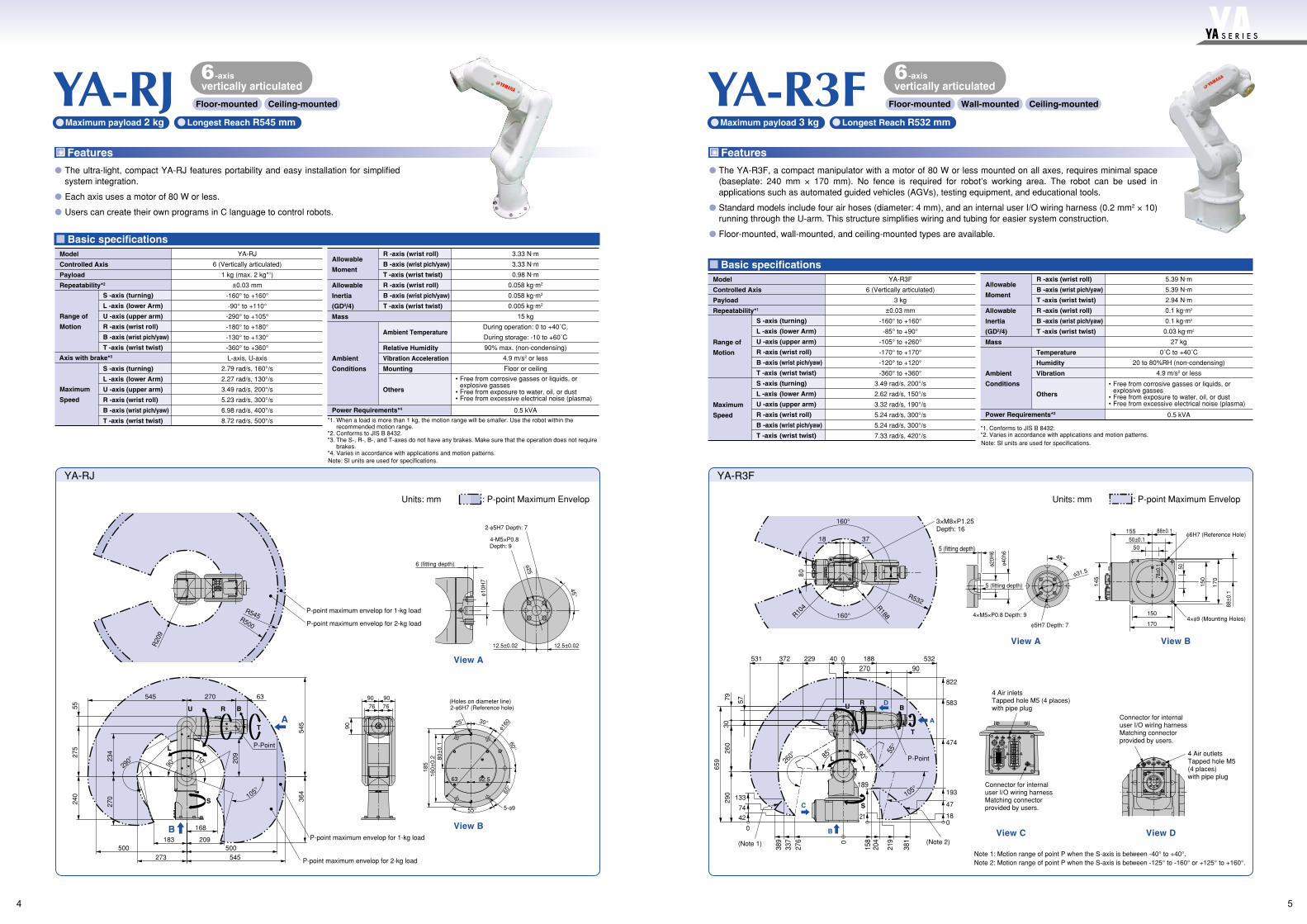
Features
The ultra-light, compact YA-RJ features portability and easy installation for simplified system integration.
Each axis uses a motor of 80 W or less.
Users can create their own programs in C language to control robots.
The YA-R3F, a compact manipulator with a motor of 80 W or less mounted on all axes, requires minimal space (baseplate: 240 mm × 170 mm). No fence is required for robot’s working area. The robot can be used in applications such as automated guided vehicles (AGVs), testing equipment, and educational tools.
Standard models include four air hoses (diameter: 4 mm), and an internal user I/O wiring harness (0.2 mm2 × 10) running through the U-arm. This structure simplifies wiring and tubing for easier system construction.
Floor-mounted, wall-mounted, and ceiling-mounted types are available.
Features
YA-RJ Longest Reach R545 mmMaximum payload 2 kg Longest Reach R532 mmMaximum payload 3 kg
Floor-mounted Ceiling-mounted
-axisvertically articulated
Floor-mounted Wall-mounted Ceiling-mounted
6-axis6vertically articulated
: P-point Maximum Envelop
View B
View A
90
909076 76
A
B
500
P-point maximum envelop for 1-kg load
P-point maximum envelop for 2-kg load
P-PointL
U
S
R B
T
545
545
364
240
275
55
270 63
110° 209
234
270
545
209183
273
168
105°
290°
500
90°
45°φ10H
7
12.5±0.02 12.5±0.02
6 (fitting depth)
4-M5×P0.8Depth: 9
2-φ5H7 Depth: 7
25° 30°
60°
60°
55°
92.563
80±
0.1
160±
0.2
185
(Holes on diameter line)2-φ6H7 (Reference hole)
5-φ9
φ160
φ25
R20
9
P-point maximum envelop for 1-kg load
P-point maximum envelop for 2-kg load
R545R500
Axis with brake*3
Note: SI units are used for specifications.
*1. When a load is more than 1 kg, the motion range will be smaller. Use the robot within the recommended motion range.
*2. Conforms to JIS B 8432.*3. The S-, R-, B-, and T-axes do not have any brakes. Make sure that the operation does not require
brakes.*4. Varies in accordance with applications and motion patterns.
Note: SI units are used for specifications.
*1. Conforms to JIS B 8432.*2. Varies in accordance with applications and motion patterns.
Units: mm : P-point Maximum EnvelopUnits: mm
54
S E R I E S
YA-R5F/YA-R5LF
Basic specifications
YA-R5F / YA-R5LF
YA-R6F
Basic specifications
YA-R6F
• Free from corrosive gasses or liquids, or explosive gasses
• Free from exposure to water, oil, or dust• Free from excessive electrical noise (plasma)
YA-R5F
±0.02 mm
-136° to +255°
6.56 rad/s, 376°/s
6.11 rad/s, 350°/s
6.98 rad/s, 400°/s
6 (Vertically articulated)
5 kg
-170° to +170°
-65° to +150°
-190° to +190°
-135° to +135°
-360° to +360°
7.85 rad/s, 450°/s
7.85 rad/s, 450°/s
12.57 rad/s, 720°/s
YA-R5LF
±0.03 mm
-138° to +255°
4.71 rad/s, 270°/s
4.89 rad/s, 280°/s
5.24 rad/s, 300°/s
YA-R5F
27 kg
YA-R5LF
29 kg
Allowable
Moment
Allowable
Inertia
(GD2/4)
Ambient
Conditions
S -axis (turning)
L -axis (lower Arm)
U -axis (upper arm)
R -axis (wrist roll)
B -axis (wrist pich/yaw)
T -axis (wrist twist)
S -axis (turning)
L -axis (lower Arm)
U -axis (upper arm)
R -axis (wrist roll)
B -axis (wrist pich/yaw)
T -axis (wrist twist)
R -axis (wrist roll)
B -axis (wrist pich/yaw)
T -axis (wrist twist)
R -axis (wrist roll)
B -axis (wrist pich/yaw)
T -axis (wrist twist)
Temperature
Humidity
Vibration
Others
Range of
Motion
Maximum
Speed
Model
Controlled Axis
Payload
Repeatability*1
Power Requirements*2
Mass
Model
12 N.m
12 N.m
7 N.m
0.3 kg.m2
0.3 kg.m2
0.1 kg.m2
0 to +45°C
20 to 80%RH (non-condensing)
4.9 m/s2 or less
1.0 kVA
4×φ12 (Mounting Holes)
2×φ6H7
φ12H
7
φ5H7 Depth: 7
φ12H7
4×φ12(Mounting Holes)
2×φ6H7
φ12H7
YA-R5F YA-R5LF
View E
R235
R706
4×M4×P0.7 Depth: 8
2×M4×P0.7 Depth: 8
87
70 55
298
423
40
25
110
170°
170°
4×M8×P1.25Depth: 16
4×M5×P0.8 Depth: 945°
5 (fitting depth)
View A
109 109
105 100±0.05
92±0
.192
±0.1
66±0.160±0.1
85±0
.1
View C
160194
160
138 10
0±0.0
519
4
310
330
40
740
0178
60
65°
150°
203
24351
136°
B
C
P-Point
S
L
U
R
B
T
A
156
0
246
239
474
688
88 80
233
947
0 15 235
706
277
501
114
305
255°
4×M8×P1.25 Depth: 16
R895
2×M4×P0.7 Depth: 8
523
170°
170°
1102540
87
70 55398
R2674×M4×P0.7Depth: 8
138
105 100±0.05
92±0
.192
±0.1
66±0.160±0.1
85±0
.1
100±
0.05
160194
160
194
Air inletTapped holes PT1/4(with pipe plug)
Connector for internal user I/O wiring harness Matching connector provided by users.
Air inletTapped holes PT1/4(with pipe plug)
Connector for internal user I/O wiring harness Matching connector provided by users.
View B View D
1BC
2BC
3BC 4BCAIR1
AIR2
109 109
9 0
88
681
400
267
895
330
400
40
341
98
503
1137
808
198
0
423
132
80
830
60
S
L
U
R B T
405
P-Point65° 150°32°
138°
255°
A
D
E
0 14 288
317
209
37°37°
φ31.5
YA-R6F
6 (Vertically articulated)
6 kg
±0.08 mm
-170° to +170°
-90° to +155°
-175° to +250°
-180° to +180°
-45° to +225°
-360° to +360°
3.84 rad/s, 220°/s
3.49 rad/s, 200°/s
3.84 rad/s, 220°/s
7.16 rad/s, 410°/s
7.16 rad/s, 410°/s
10.65 rad/s, 610°/s
Allowable
Moment
Allowable
Inertia
(GD2/4)
Ambient
Conditions
11.8 N.m
9.8 N.m
5.9 N.m
0.27 kg.m2
0.27 kg.m2
0.06 kg.m2
130 kg
0 to +45°C
20 to 80 %RH (non-condensing)
4.9 m/s2 or less
1.0 kVA
• Free from corrosive gasses or liquids, or explosive gasses
• Free from exposure to water, oil, or dust• Free from excessive electrical noise (plasma)
S -axis (turning)
L -axis (lower Arm)
U -axis (upper arm)
R -axis (wrist roll)
B -axis (wrist pich/yaw)
T -axis (wrist twist)
S -axis (turning)
L -axis (lower Arm)
U -axis (upper arm)
R -axis (wrist roll)
B -axis (wrist pich/yaw)
T -axis (wrist twist)
R -axis (wrist roll)
B -axis (wrist pich/yaw)
T -axis (wrist twist)
R -axis (wrist roll)
B -axis (wrist pich/yaw)
T -axis (wrist twist)
Temperature
Humidity
Vibration
Others
Range of
Motion
Maximum
Speed
Model
Controlled Axis
Payload
Repeatability*1
Power Requirements*2
Mass
φ25H7
φ50h6
φ6H7 Depth: 6
4×φ18
φ12H7
2×φ16H7
View A View B
View C
φ40
45˚
4×M6×P1.0Depth: 9
175˚
83˚
90˚
155˚
250˚
614
155
95
6401507545
0
1422
381
349
152
0309
637
1122
1722
681
352
05
204316
764
538 0
501
L
B
T
R
U12
94
130
S
P-Point
R270
R1422
R381
170˚
170˚
6
6
A
B
C
199188
141
1BC
2BC
3BC
Connector for internal user I/O wiring harness (with cap)Matching connector provided by users.
Welding power source’sterminal block (with cover)Cover type is TCV-2001-04
Air inlet PT3/8with pipe plug (B)
Air inlet PT3/8with pipe plug (A)
102±0.1
153±0.1
153±
0.1
130±
0.1
100±0.1
300
292
260
102±
0.1
132±
0.1
60
132±0.1240
300
260
60
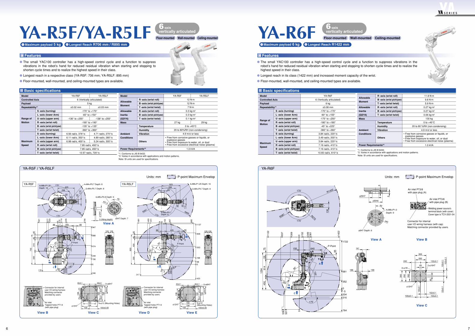
FeaturesFeatures
76
S E R I E S
-axis
Floor-mounted Wall-mounted Ceiling-mounted
6vertically articulated
-axis
Floor-mounted Wall-mounted Ceiling-mounted
6vertically articulated
Longest Reach R706 mm / R895 mmMaximum payload 5 kg Longest Reach R1422 mmMaximum payload 6 kg
Note: SI units are used for specifications.
*1. Conforms to JIS B 8432.*2. Varies in accordance with applications and motion patterns. Note: SI units are used for specifications.
*1. Conforms to JIS B 8432.*2. Varies in accordance with applications and motion patterns.
The small YAC100 controller has a high-speed control cycle and a function to suppress vibrations in the robot’s hand for reduced residual vibration when starting and stopping to shorten cycle times and to realize the highest speed in their class.
Longest reach in a respective class (YA-R5F: 706 mm; YA-R5LF: 895 mm)
Floor-mounted, wall-mounted, and ceiling-mounted types are available.
The small YAC100 controller has a high-speed control cycle and a function to suppress vibrations in the robot’s hand for reduced residual vibration when starting and stopping to shorten cycle times and to realize the highest speed in their class.
Longest reach in its class (1422 mm) and increased moment capacity of the wrist.
Floor-mounted, wall-mounted, and ceiling-mounted types are available.
: P-point Maximum EnvelopUnits: mm : P-point Maximum EnvelopUnits: mm
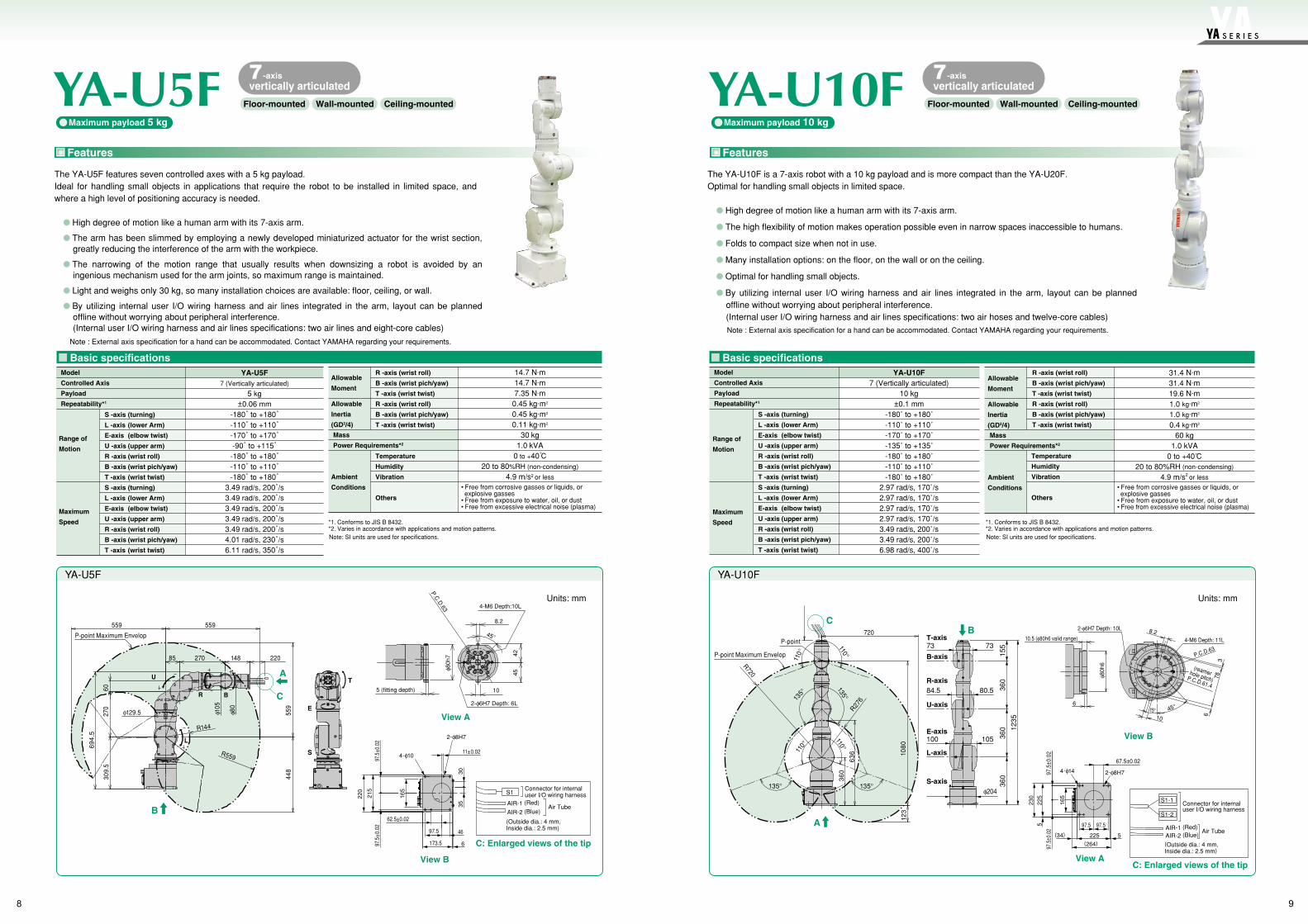
YA-U5FMaximum payload 5 kg Maximum payload 10 kg
Note : External axis specification for a hand can be accommodated. Contact YAMAHA regarding your requirements.
Note : External axis specification for a hand can be accommodated. Contact YAMAHA regarding your requirements.
The YA-U5F features seven controlled axes with a 5 kg payload.Ideal for handling small objects in applications that require the robot to be installed in limited space, and where a high level of positioning accuracy is needed.
High degree of motion like a human arm with its 7-axis arm.
The arm has been slimmed by employing a newly developed miniaturized actuator for the wrist section, greatly reducing the interference of the arm with the workpiece.
The narrowing of the motion range that usually results when downsizing a robot is avoided by an ingenious mechanism used for the arm joints, so maximum range is maintained.
Light and weighs only 30 kg, so many installation choices are available: floor, ceiling, or wall.
By utilizing internal user I/O wiring harness and air lines integrated in the arm, layout can be planned offline without worrying about peripheral interference.(Internal user I/O wiring harness and air lines specifications: two air lines and eight-core cables)
Features
YA-U10F
Basic specifications
The YA-U10F is a 7-axis robot with a 10 kg payload and is more compact than the YA-U20F.Optimal for handling small objects in limited space.
High degree of motion like a human arm with its 7-axis arm.
The high flexibility of motion makes operation possible even in narrow spaces inaccessible to humans.
Folds to compact size when not in use.
Many installation options: on the floor, on the wall or on the ceiling.
Optimal for handling small objects.
By utilizing internal user I/O wiring harness and air lines integrated in the arm, layout can be planned offline without worrying about peripheral interference.(Internal user I/O wiring harness and air lines specifications: two air hoses and twelve-core cables)
Features
Range of
Motion
Maximum
Speed
Model
Controlled Axis
Payload
Repeatability*1
S -axis (turning)
L -axis (lower Arm)
E-axis (elbow twist)
U -axis (upper arm)
R -axis (wrist roll)
B -axis (wrist pich/yaw)
T -axis (wrist twist)
S -axis (turning)
L -axis (lower Arm)
E-axis (elbow twist)
U -axis (upper arm)
R -axis (wrist roll)
B -axis (wrist pich/yaw)
T -axis (wrist twist)
YA-U10F7 (Vertically articulated)
10 kg±0.1 mm
-180˚ to +180˚-110˚ to +110˚-170˚ to +170˚-135˚ to +135˚-180˚ to +180˚-110˚ to +110˚-180˚ to +180˚
2.97 rad/s, 170˚/s2.97 rad/s, 170˚/s2.97 rad/s, 170˚/s2.97 rad/s, 170˚/s3.49 rad/s, 200˚/s3.49 rad/s, 200˚/s6.98 rad/s, 400˚/s
C: Enlarged views of the tip
Connector for internaluser I/O wiring harness
S1-2
S1-1
AIR-1 (Red)AIR-2 (Blue)
(Outside dia.: 4 mm,Inside dia.: 2.5 mm)
Air Tube
View A
97.5 97.5
225(34)
225
5
5
97.5
± 0.0
297
.5± 0
.02
67.5±0.02
230
4-φ14 2-φ8H7
(264)
165
Allowable
Moment
Allowable
Inertia
(GD2/4)
Ambient
Conditions
R -axis (wrist roll)
B -axis (wrist pich/yaw)
T -axis (wrist twist)
R -axis (wrist roll)
B -axis (wrist pich/yaw)
T -axis (wrist twist)
Temperature
Humidity
Vibration
Others
31.4 N.m31.4 N.m19.6 N.m1.0 kg.m2
1.0 kg.m2
0.4 kg.m2
60 kg1.0 kVA
0 to +40 C20 to 80%RH (non-condensing)
4.9 m/s2 or less
• Free from corrosive gasses or liquids, or explosive gasses
• Free from exposure to water, oil, or dust• Free from excessive electrical noise (plasma)
Mass
Power Requirements*2
Allowable
Moment
Allowable
Inertia
(GD2/4)
Ambient
Conditions
Mass
Power Requirements*2
R -axis (wrist roll)
B -axis (wrist pich/yaw)
T -axis (wrist twist)
R -axis (wrist roll)
B -axis (wrist pich/yaw)
T -axis (wrist twist)
Temperature
Humidity
Vibration
Others
Basic specifications
Range of
Motion
Maximum
Speed
Model
Controlled Axis
Payload
Repeatability*1
S -axis (turning)
L -axis (lower Arm)
E-axis (elbow twist)
U -axis (upper arm)
R -axis (wrist roll)
B -axis (wrist pich/yaw)
T -axis (wrist twist)
S -axis (turning)
L -axis (lower Arm)
E-axis (elbow twist)
U -axis (upper arm)
R -axis (wrist roll)
B -axis (wrist pich/yaw)
T -axis (wrist twist)
YA-U5F7 (Vertically articulated)
5 kg±0.06 mm
-180˚ to +180˚-110˚ to +110˚-170˚ to +170˚-90˚ to +115˚
-180˚ to +180˚-110˚ to +110˚-180˚ to +180˚
3.49 rad/s, 200˚/s3.49 rad/s, 200˚/s3.49 rad/s, 200˚/s3.49 rad/s, 200˚/s3.49 rad/s, 200˚/s4.01 rad/s, 230˚/s6.11 rad/s, 350˚/s
14.7 N.m14.7 N.m7.35 N.m
0.45 kg.m2
0.45 kg.m2
0.11 kg.m2
30 kg1.0 kVA
0 to +40 C20 to 80%RH (non-condensing)
4.9 m/s2 or less
• Free from corrosive gasses or liquids, or explosive gasses
• Free from exposure to water, oil, or dust• Free from excessive electrical noise (plasma)
YA-U5F
Units: mm Units: mm
C: Enlarged views of the tip
S1Connector for internaluser I/O wiring harness
AIR-1 (Red)
AIR-2 (Blue)
(Outside dia.: 4 mm, Inside dia.: 2.5 mm)
Air Tube
View B
97.5
±0.0
297
.5±0
.02
215
3530
220
4-φ10
62.5±0.02
97.5 46
173.5 6
11±0.02
2-φ8H7
165
694.
5
309.
527
060
φ129.5
R144
R559
559
P-point Maximum Envelop
U
L
R B
559
85 270 148
φ105
φ80
220
559
448
S
E
T
B
155
360
φ204
105100
80.584.5
7373
360
360
1235
T-axis
B-axis
R-axis
U-axis
E-axis
L-axis
S-axis
B
C
A
View A
45°
8.2
4-M6 Depth:10L
P.C.D
.63
5 (fitting depth)
2-φ6H7 Depth: 6L
φ80h
7 4245
10
YA-U10F
A
C720
P-point
P-point Maximum Envelop
R720
135°
135°
R276
1080
135°135°11
0°
110°
110°
110°
636
360
123
2-φ6H7 Depth: 10L
10.5 (φ80h6 valid range)
φ80h
6
6
8.24-M6 Depth: 11L
P.C.D.63
3
6
78
45°
1015°
(reamer hole pitch)P.C.D.61.4
View B
98
S E R I E S
-axis
Floor-mounted Wall-mounted Ceiling-mounted
7vertically articulated
-axis
Floor-mounted Wall-mounted Ceiling-mounted
7vertically articulated
Note: SI units are used for specifications.
*1. Conforms to JIS B 8432.*2. Varies in accordance with applications and motion patterns.
Note: SI units are used for specifications.
*1. Conforms to JIS B 8432.*2. Varies in accordance with applications and motion patterns.
YA-U20F
Basic specifications
YAC100 Controller Specifications Programming Pendant Specifications
Features
Range of
Motion
Maximum
Speed
Model
Controlled Axis
Payload
Repeatability*1
S -axis (turning)
L -axis (lower Arm)
E-axis (elbow twist)
U -axis (upper arm)
R -axis (wrist roll)
B -axis (wrist pich/yaw)
T -axis (wrist twist)
S -axis (turning)
L -axis (lower Arm)
E-axis (elbow twist)
U -axis (upper arm)
R -axis (wrist roll)
B -axis (wrist pich/yaw)
T -axis (wrist twist)
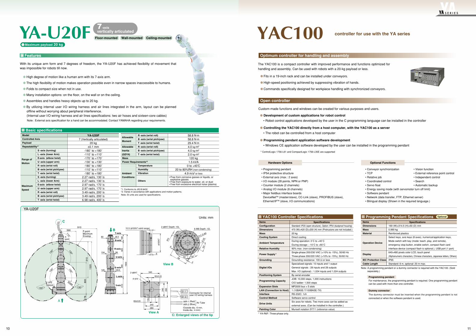
YA-U20F7 (Vertically articulated)
20 kg±0.1 mm
-180˚ to +180˚-110˚ to +110˚-170˚ to +170˚-130˚ to +130˚-180˚ to +180˚-110˚ to +110˚-180˚ to +180˚
2.27 rad/s, 130˚/s2.27 rad/s, 130˚/s2.97 rad/s, 170˚/s2.97 rad/s, 170˚/s3.49 rad/s, 200˚/s3.49 rad/s, 200˚/s6.98 rad/s, 400˚/s
180
420
490 15
00
410
T-axis
B-axis
R-axis
U-axis
E-axis
L-axis
S-axis
85.5
98
109.5
80
104
120
C: Enlarged views of the tip
View B
Connector for internaluser I/O wiring harness
S1-2
S1-1
AIR-1 (Red)AIR-2 (Blue)
(Outside dia.: 6 mm,Inside dia.: 4 mm)
Air Tube
View A280
280
340
240
240
4-φ14
2-φ8H7
60±0.03
60±0.03 130±
0.03
Allowable
Moment
Allowable
Inertia
(GD2/4)
Ambient
Conditions
R -axis (wrist roll)
B -axis (wrist pich/yaw)
T -axis (wrist twist)
R -axis (wrist roll)
B -axis (wrist pich/yaw)
T -axis (wrist twist)
Temperature
Humidity
Vibration
Others
58.8 N.m58.8 N.m29.4 N.m4.0 kg.m2
4.0 kg.m2
2.0 kg.m2
120 kg1.5 kVA
0 to +40 C20 to 80%RH (non-condensing)
4.9 m/s2 or less
• Free from corrosive gasses or liquids, or explosive gasses
• Free from exposure to water, oil, or dust• Free from excessive electrical noise (plasma)
Mass
Power Requirements*2
The YAC100 is a compact controller with improved performance and functions optimized for
handling and assembly. Can be used with robots with a 20-kg payload or less.
Fits in a 19-inch rack and can be installed under conveyors.
High-speed positioning achieved by suppressing vibration of hands.
Commands specifically designed for workpiece handling with synchronized conveyors.
YAC100
Items
Configuration
Dimensions
Mass
Cooling System
Ambient Temperature
Relative Humidity
Power Supply *
Grounding
Digital l/Os
Positioning System
Programming Capacity
Expansion Slots
LAN (Connection to Host)
Interface
Control Method
Drive Units
Painting Color
Standard: IP20 (open structure), Option: IP54 (dustproof housing)
470 (W)×420 (D)×200 (H) mm (Protrusions are not included.)
20 kg
Direct cooling
During operation: 0˚C to +40˚C
During storage : -10˚C to +60˚C
90% max. (non-condensing)
Single-phase 200/230 VAC (+10% to -15%), 50/60 Hz
Three-phase 200/220 VAC (+10% to -15%), 50/60 Hz
Grounding resistance: 100 Ω or less
Specialized signals: 10 inputs and 1 output
General signals : 28 inputs and 28 outputs
Max. I/O (optional) : 1,024 inputs and 1,024 outputs
By serial encoder
JOB: 10,000 steps, 1,000 instructions
CIO ladder: 1,500 steps
MP2000 bus × 5 slots
1 (10BASE-T/100BASE-TX)
RS-232C: 1ch
Software servo control
Six axes for robots. Two more axes can be added as
external axes. (Can be installed in the controller.)
Munsell notation 5Y7/1 (reference value)
Items
Dimensions
Mass
Material
Operation Device
Display
IEC Protection Class
Cable Length
169 (W)×314.5 (H)×50 (D) mm
0.990 kg
Reinforced plastics
Select keys, axis keys (8 axes), numerical/application keys,
Mode switch with key (mode: teach, play, and remote),
emergency stop button, enable switch, compact flash card
interface device (compact flash is optional.), USB port (1 port)
640×480 pixels color LCD, touch panel
(Alphanumeric characters, Chinese characters, Japanese letters, Others)
IP65
Standard: 8 m, optional: 20 m max.
SpecificationsSpecifications
Note: A programming pendant or a dummy connector is required with the YAC100. (Sold separately.)
Programming pendant
For maintenance, the programming pendant is required. One programming pendant can be used with more than one controller.
Dummy connector
The dummy connector must be inserted when the programming pendant is not
connected or when the software pendant is used.
Custom-made functions and windows can be created for various purposes and users.
Development of custom applications for robot control
• Robot control applications developed by the user in the C programming language can be installed in the controller
Controlling the YAC100 directly from a host computer, with the YAC100 as a server
• The robot can be controlled from a host computer
Programming pendant application software development
• Windows CE application software developed by the user can be installed in the programming pendant
Hardware Options Optional Functions
• Programming pendant• IP54 protective structure• External axis (max.: 2 axes)• I/O module (28 points, NPN or PNP)• Counter module (2 channels)• Analog I/O module (8 channels)• Major fieldbus interface boards
DeviceNetTM (master/slave), CC-Link (slave), PROFIBUS (slave),Ethernet/IPTM (slave, I/O communications)
• Conveyor synchronization• TCP• Relative job• Coordinated control• Servo float• Energy saving mode (with servomotor turn off limit)• Software pendant• Network (data transfer, FTP, Ethernet server)• Bilingual display (Shown in the required language.)
• Vision function• External reference point control• Independent control• Search• Automatic backup
controller for use with the YA series
Optimum controller for handling and assembly
Open controller
* ControlLogix 1756-L61 and CompactLogix 1756-L35E are supported
* YA-R6F: Three-phase only.
Optional
YA-U20F
Units: mm
B
A
C
10.5 (φ100h7 valid range)
φ10
0h7
6
2-φ8H7 Depth: 10L
φ10
P.C.D.80
8.25
30°
30°30°98
3
6
910390
110°
110°
130° 130°
130° 130°
P-point
P-point Maximum Envelop
R390Lamp
(optional)130°
800
178
910
1320
130°
1110
S E R I E S
-axis
Floor-mounted Wall-mounted Ceiling-mounted
7vertically articulated
Maximum payload 20 kg
Note : External axis specification for a hand can be accommodated. Contact YAMAHA regarding your requirements.
With its unique arm form and 7 degrees of freedom, the YA-U20F has achieved flexibility of movement that was impossible for robots till now.
High degree of motion like a human arm with its 7-axis arm.
The high flexibility of motion makes operation possible even in narrow spaces inaccessible to humans.
Folds to compact size when not in use.
Many installation options: on the floor, on the wall or on the ceiling.
Assembles and handles heavy objects up to 20 kg.
By utilizing internal user I/O wiring harness and air lines integrated in the arm, layout can be planned offline without worrying about peripheral interference.(Internal user I/O wiring harness and air lines specifications: two air hoses and sixteen-core cables)
Note: SI units are used for specifications.
*1. Conforms to JIS B 8432.*2. Varies in accordance with applications and motion patterns.
6-M8 Depth: 12L