Embed Size (px)
Citation preview
Owner’s Guide.
2012
November 2011
Second Printing
Owner’s Guide
FORD Flex
Litho in USA
fordowner.com
www.ford.ca
2012Owner’s Guide.
CA8J 19A321 AB
Introduction 5
Instrument Cluster 14
Warning lights and chimes 14Gauges 18Message center 20
Entertainment Systems 30
AM/FM stereo with CD/MP3 30Auxiliary input jack (Line in) 39USB port 41Satellite radio information 44Family entertainment system 48Navigation system 68SYNC� 68
Climate Controls 69
Manual heating and air conditioning 69Dual electronic automatic temperature control 72Navigation system based climate control 75Rear window defroster 81
Lights 82
Headlamps 82Turn signal control 86Interior lamps 86Bulb replacement 87
Driver Controls 92
Windshield wiper/washer control 92Steering wheel adjustment 93Power windows 102Mirrors 103Speed control 105Moonroof 109
Table of Contents
1
2012 Flex (471)Owners Guide, 2nd PrintingUSA (fus)
Locks and Security 122
Keys 122Locks 128Anti-theft system 139
Seating and Safety Restraints 145
Seating 145Personal Safety System™ 167Safety belt system 170Airbags 181Child restraints 195
Tires, Wheels and Loading 214
Tire information 216Tire inflation 218Tire Pressure Monitoring System (TPMS) 231Vehicle loading 236Trailer towing 243Recreational towing 247
Driving 249
Starting 249Brakes 254AdvanceTrac� 257Transmission operation 265Reverse sensing system 271Rear-view camera system 273All wheel drive 280
Table of Contents
2
2012 Flex (471)Owners Guide, 2nd PrintingUSA (fus)
Roadside Emergencies 287
Getting roadside assistance 287Hazard flasher control 288Fuel pump shut-off 288Fuses and relays 289Changing tires 297Wheel lug nut torque 303Jump starting 305Wrecker towing 308
Customer Assistance 310
Reporting safety defects (U.S. only) 316Reporting safety defects (Canada only) 317
Cleaning 318
Maintenance and Specifications 326
Engine compartment 328Changing the wiper blades 331Engine oil 332Battery 336Engine coolant 338Fuel information 345Air filter(s) 363Part numbers 366Maintenance product specifications and capacities 367Engine data 371
Table of Contents
3
2012 Flex (471)Owners Guide, 2nd PrintingUSA (fus)
Accessories 375
Ford Extended Service Plan 378
Scheduled Maintenance 382
Normal scheduled maintenance and log 388
Index 400
The information contained in this publication was correct at the time of going toprint. In the interest of continuous development, we reserve the right to changespecifications, design or equipment at any time without notice or obligation. Nopart of this publication may be reproduced, transmitted, stored in a retrievalsystem or translated into any language in any form by any means without ourwritten permission. Errors and omissions excepted.
© Ford Motor Company 2011
Table of Contents
4
2012 Flex (471)Owners Guide, 2nd PrintingUSA (fus)
CONGRATULATIONSCongratulations on acquiring your new Ford. Please take the time to getwell acquainted with your vehicle by reading this handbook. The moreyou know and understand about your vehicle, the greater the safety andpleasure you will derive from driving it.
For more information on Ford Motor Company and its products visit thefollowing website:
• In the United States: www.ford.com
• In Canada: www.ford.ca
• In Australia: www.ford.com.au
• In Mexico: www.ford.com.mx
Additional owner information is given in separate publications.
This Owner’s Guide describes every option and model variant availableand therefore some of the items covered may not apply to yourparticular vehicle. Furthermore, due to printing cycles it may describeoptions before they are generally available.
Remember to pass on this Owner’s Guide when reselling the vehicle. It isan integral part of the vehicle.
WARNING: Fuel pump shut-off: In the event of an accidentthis feature will automatically cut off the fuel supply to the
engine. It can also be activated through sudden vibration (e.g. collisionwhen parking). To restart your vehicle, refer to Fuel pump shut-off inthe Roadside Emergencies chapter.
Introduction
5
2012 Flex (471)Owners Guide, 2nd PrintingUSA (fus)
SAFETY AND ENVIRONMENT PROTECTION
Warning symbols in this guide
How can you reduce the risk of personal injury to yourself or others? Inthis guide, answers to such questions are contained in commentshighlighted by the warning triangle symbol. These comments should beread and observed.
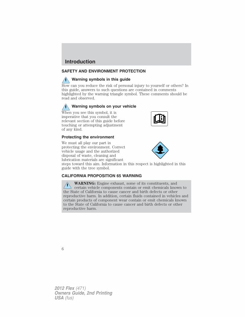
Warning symbols on your vehicle
When you see this symbol, it isimperative that you consult therelevant section of this guide beforetouching or attempting adjustmentof any kind.
Protecting the environmentWe must all play our part inprotecting the environment. Correctvehicle usage and the authorizeddisposal of waste, cleaning andlubrication materials are significantsteps toward this aim. Information in this respect is highlighted in thisguide with the tree symbol.
CALIFORNIA PROPOSITION 65 WARNING
WARNING: Engine exhaust, some of its constituents, andcertain vehicle components contain or emit chemicals known to
the State of California to cause cancer and birth defects or otherreproductive harm. In addition, certain fluids contained in vehicles andcertain products of component wear contain or emit chemicals knownto the State of California to cause cancer and birth defects or otherreproductive harm.
Introduction
6
2012 Flex (471)Owners Guide, 2nd PrintingUSA (fus)
PERCHLORATE MATERIALCertain components of this vehicle such as airbag modules, safety beltpretensioners, and button cell batteries may contain Perchlorate Material– Special handling may apply for service or vehicle end of life disposal.See www.dtsc.ca.gov/hazardouswaste/perchlorate.
BREAKING-IN YOUR VEHICLEYour vehicle does not need an extensive break-in. Try not to drivecontinuously at the same speed for the first 1,000 miles (1,600 km) ofnew vehicle operation. Vary your speed frequently in order to give themoving parts a chance to break in.
Drive your new vehicle at least 1,000 miles (1,600 km) before towing atrailer. For more detailed information about towing a trailer, refer toTrailer towing in the Tires, Wheels and Loading chapter.
Do not add friction modifier compounds or special break-in oils sincethese additives may prevent piston ring seating. See Engine oil in theMaintenance and Specifications chapter for more information on oilusage.
SPECIAL NOTICES
New Vehicle Limited WarrantyFor a detailed description of what is covered and what is not covered byyour vehicle’s New Vehicle Limited Warranty, refer to the WarrantyGuide that is provided to you along with your Owner’s Guide.
Special instructionsFor your added safety, your vehicle is fitted with sophisticated electroniccontrols.
WARNING: Please read the section Airbag SupplementalRestraint System (SRS) in the Seating and Safety Restraints
chapter. Failure to follow the specific warnings and instructions couldresult in personal injury.
WARNING: Front seat mounted rear-facing child or infant seatsshould NEVER be placed in front of an active passenger airbag.
Introduction
7
2012 Flex (471)Owners Guide, 2nd PrintingUSA (fus)
DATA RECORDING
Service Data RecordingService data recorders in your vehicle are capable of collecting andstoring diagnostic information about your vehicle. This potentiallyincludes information about the performance or status of various systemsand modules in the vehicle, such as engine, throttle, steering or brakesystems. In order to properly diagnose and service your vehicle, FordMotor Company, Ford of Canada, and service and repair facilities mayaccess or share among them vehicle diagnostic information receivedthrough a direct connection to your vehicle when diagnosing or servicingyour vehicle. For U.S. only (if equipped), if you choose to use the SYNC�Vehicle Health Report, you consent that certain diagnostic informationmay also be accessed electronically by Ford Motor Company and Fordauthorized service facilities, and that the diagnostic information may beused for any purpose. See your SYNC� supplement for more information.
Event Data RecordingThis vehicle is equipped with an event data recorder (EDR). Themain purpose of an EDR is to record, in certain crash or nearcrash-like situations, such as an airbag deployment or hitting aroad obstacle; this data will assist in understanding how avehicle’s systems performed. The EDR is designed to record datarelated to vehicle dynamics and safety systems for a short periodof time, typically 30 seconds or less. The EDR in this vehicle isdesigned to record such data as:
• How various systems in your vehicle were operating;
• Whether or not the driver and passenger safety belts werebuckled/fastened;
• How far (if at all) the driver was depressing the acceleratorand/or the brake pedal; and
• How fast the vehicle was travelling; and
• Where the driver was positioning the steering wheel.
Introduction
8
2012 Flex (471)Owners Guide, 2nd PrintingUSA (fus)
This data can help provide a better understanding of thecircumstances in which crashes and injuries occur.
Note: EDR data is recorded by your vehicle only if a non-trivialcrash situation occurs; no data is recorded by the EDR undernormal driving conditions and no personal data or information(e.g., name, gender, age, and crash location) is recorded (seelimitations regarding 911 Assist and Traffic, directions andInformation privacy below). However, parties, such as lawenforcement, could combine the EDR data with the type ofpersonally identifying data routinely acquired during a crashinvestigation.
To read data recorded by an EDR, special equipment is required,and access to the vehicle or the EDR is needed. In addition to thevehicle manufacturer, other parties, such as law enforcement,that have such special equipment, can read the information ifthey have access to the vehicle or the EDR. Ford Motor Companyand Ford of Canada do not access event data recorderinformation without obtaining consent, unless pursuant to courtorder or where required by law enforcement, other governmentauthorities or other third parties acting with lawful authority.Other parties may seek to access the information independentlyof Ford Motor Company and Ford of Canada.
Note: Including to the extent that any law pertaining to EventData Recorders applies to SYNC� or its features, please note thefollowing: Once 911 Assist (if equipped) is enabled (set ON), 911Assist may, through any paired and connected cell phone, discloseto emergency services that the vehicle has been in a crashinvolving the deployment of an airbag or, in certain vehicles, theactivation of the fuel pump shut-off. Certain versions or updatesto 911 Assist may also be capable of being used to electronicallyor verbally provide to 911 operators the vehicle location (such aslatitude and longitude), and/or other details about the vehicle orcrash or personal information about the occupants to assist 911operators to provide the most appropriate emergency services. Ifyou do not want to disclose this information, do not activate the911 Assist feature. See your SYNC� supplement for moreinformation.
Introduction
9
2012 Flex (471)Owners Guide, 2nd PrintingUSA (fus)
Additionally, when you connect to Traffic, Directions andInformation (if equipped, U.S. only), the service uses GPStechnology and advanced vehicle sensors to collect the vehicle’scurrent location, travel direction, and speed (“vehicle travelinformation”), only to help provide you with the directions,traffic reports, or business searches that you request. If you donot want Ford or its vendors to receive this information, do notactivate the service. Ford Motor Company and the vendors it usesto provide you with this information do not store your vehicletravel information. For more information, see Traffic, Directionsand Information, Terms and Conditions. See your SYNC�supplement for more information.
CELL PHONE USEThe use of mobile communications equipment has become increasinglyimportant in the conduct of business and personal affairs. However,drivers must not compromise their own or others’ safety when usingsuch equipment. Mobile communications can enhance personal safetyand security when appropriately used, particularly in emergencysituations. Safety must be paramount when using mobile communicationsequipment to avoid negating these benefits.
Mobile communication equipment includes, but is not limited to, cellularphones, pagers, portable email devices, text messaging devices andportable two-way radios.
WARNING: Driving while distracted can result in loss of vehiclecontrol, accident and injury. Ford strongly recommends that you
use extreme caution when using any device or feature that may takeyour focus off the road. Your primary responsibility is the safeoperation of your vehicle.We recommend against the use of any handheld device while drivingand that you comply with all applicable laws.
Introduction
10
2012 Flex (471)Owners Guide, 2nd PrintingUSA (fus)
EXPORT UNIQUE (NON–UNITED STATES/CANADA) VEHICLESPECIFIC INFORMATIONFor your particular global region, your vehicle may be equipped withfeatures and options that are different from the features and options thatare described in this Owner’s Guide. A market unique supplement maybe supplied that complements this book. By referring to the marketunique supplement, if provided, you can properly identify those features,recommendations and specifications that are unique to your vehicle. ThisOwner’s Guide is written primarily for the U.S. and Canadian Markets.Features or equipment listed as standard may be different on units builtfor Export. Refer to this Owner’s Guide for all other requiredinformation and warnings.
Introduction
11
2012 Flex (471)Owners Guide, 2nd PrintingUSA (fus)
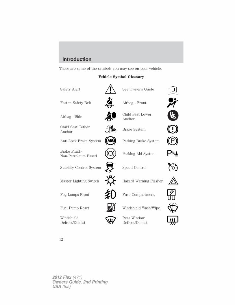
These are some of the symbols you may see on your vehicle.
Vehicle Symbol Glossary
Safety Alert See Owner’s Guide
Fasten Safety Belt Airbag - Front
Airbag - SideChild Seat LowerAnchor
Child Seat TetherAnchor
Brake System
Anti-Lock Brake System Parking Brake System
Brake Fluid -Non-Petroleum Based
Parking Aid System
Stability Control System Speed Control
Master Lighting Switch Hazard Warning Flasher
Fog Lamps-Front Fuse Compartment
Fuel Pump Reset Windshield Wash/Wipe
WindshieldDefrost/Demist
Rear WindowDefrost/Demist
Introduction
12
2012 Flex (471)Owners Guide, 2nd PrintingUSA (fus)
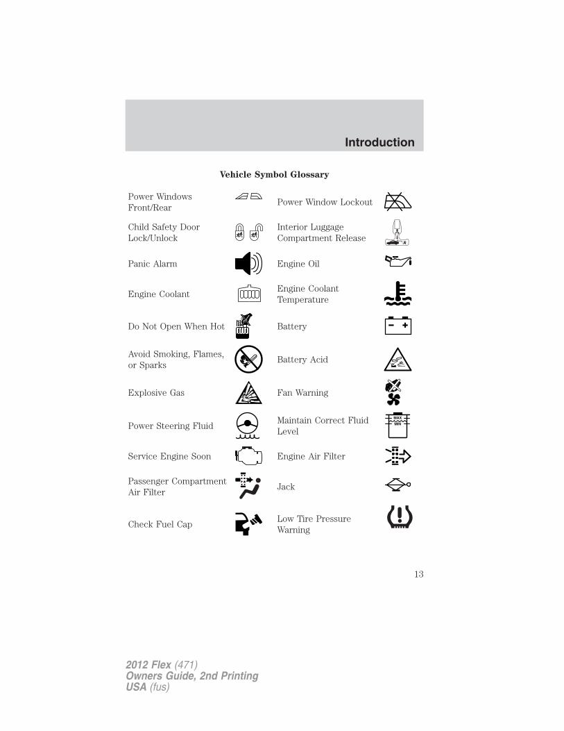
Vehicle Symbol Glossary
Power WindowsFront/Rear
Power Window Lockout
Child Safety DoorLock/Unlock
Interior LuggageCompartment Release
Panic Alarm Engine Oil
Engine CoolantEngine CoolantTemperature
Do Not Open When Hot Battery
Avoid Smoking, Flames,or Sparks
Battery Acid
Explosive Gas Fan Warning
Power Steering FluidMaintain Correct FluidLevel
MAX
MIN
Service Engine Soon Engine Air Filter
Passenger CompartmentAir Filter
Jack
Check Fuel CapLow Tire PressureWarning
Introduction
13
2012 Flex (471)Owners Guide, 2nd PrintingUSA (fus)
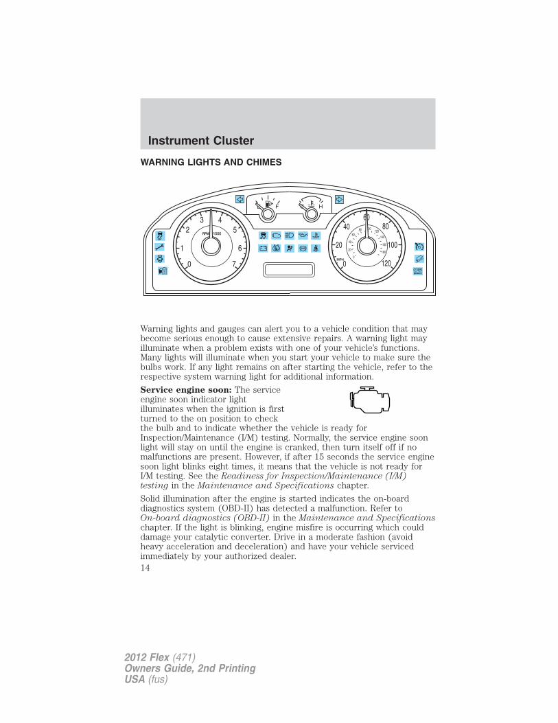
WARNING LIGHTS AND CHIMES
Warning lights and gauges can alert you to a vehicle condition that maybecome serious enough to cause extensive repairs. A warning light mayilluminate when a problem exists with one of your vehicle’s functions.Many lights will illuminate when you start your vehicle to make sure thebulbs work. If any light remains on after starting the vehicle, refer to therespective system warning light for additional information.
Service engine soon: The serviceengine soon indicator lightilluminates when the ignition is firstturned to the on position to checkthe bulb and to indicate whether the vehicle is ready forInspection/Maintenance (I/M) testing. Normally, the service engine soonlight will stay on until the engine is cranked, then turn itself off if nomalfunctions are present. However, if after 15 seconds the service enginesoon light blinks eight times, it means that the vehicle is not ready forI/M testing. See the Readiness for Inspection/Maintenance (I/M)testing in the Maintenance and Specifications chapter.
Solid illumination after the engine is started indicates the on-boarddiagnostics system (OBD-II) has detected a malfunction. Refer toOn-board diagnostics (OBD-II) in the Maintenance and Specificationschapter. If the light is blinking, engine misfire is occurring which coulddamage your catalytic converter. Drive in a moderate fashion (avoidheavy acceleration and deceleration) and have your vehicle servicedimmediately by your authorized dealer.
E F C H
RPM x 10002
0
1
3 45
6
7
60100
MPH
20
40
6080
0180
160
140
120
0
20
40 80
100
120
Instrument Cluster
14
2012 Flex (471)Owners Guide, 2nd PrintingUSA (fus)
WARNING: Under engine misfire conditions, excessive exhausttemperatures could damage the catalytic converter, the fuel
system, interior floor coverings or other vehicle components, possiblycausing a fire.
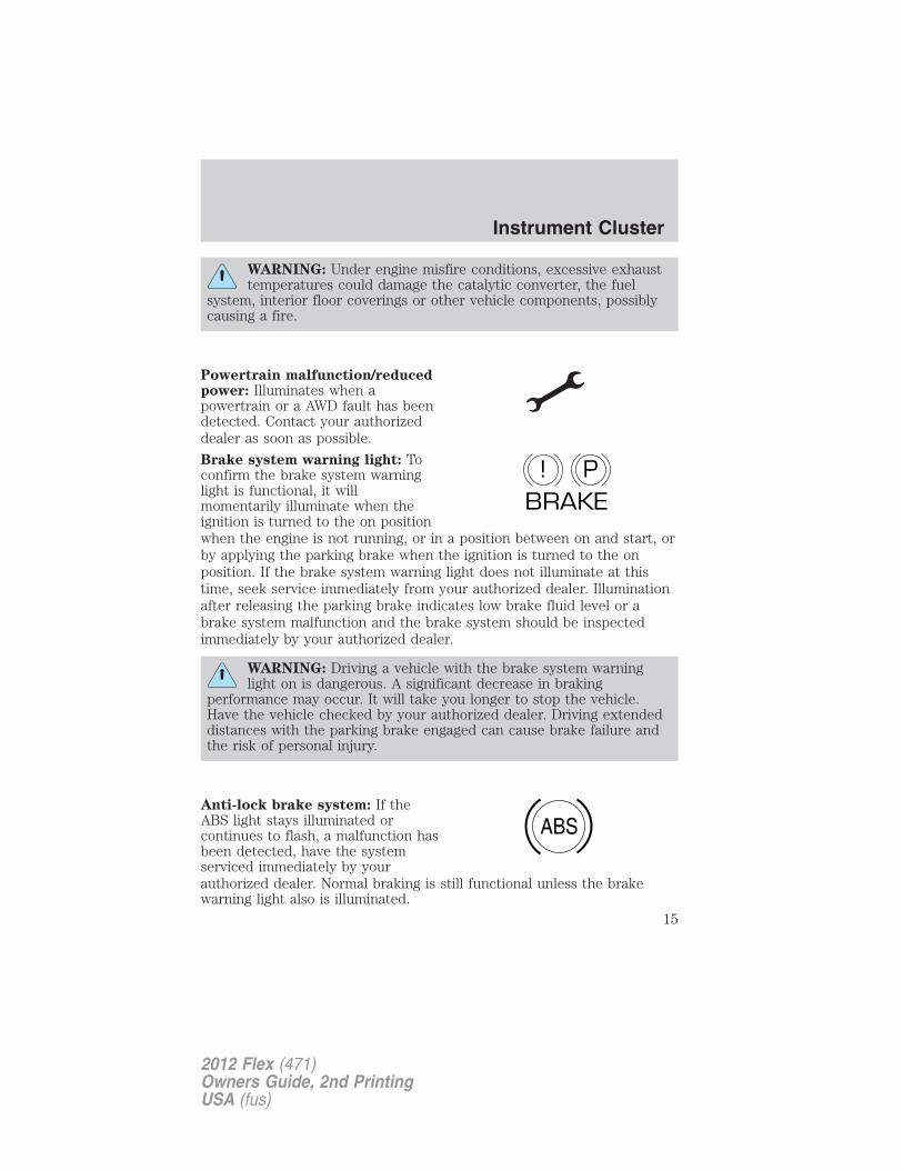
Powertrain malfunction/reducedpower: Illuminates when apowertrain or a AWD fault has beendetected. Contact your authorizeddealer as soon as possible.
Brake system warning light: Toconfirm the brake system warninglight is functional, it willmomentarily illuminate when theignition is turned to the on positionwhen the engine is not running, or in a position between on and start, orby applying the parking brake when the ignition is turned to the onposition. If the brake system warning light does not illuminate at thistime, seek service immediately from your authorized dealer. Illuminationafter releasing the parking brake indicates low brake fluid level or abrake system malfunction and the brake system should be inspectedimmediately by your authorized dealer.
WARNING: Driving a vehicle with the brake system warninglight on is dangerous. A significant decrease in braking
performance may occur. It will take you longer to stop the vehicle.Have the vehicle checked by your authorized dealer. Driving extendeddistances with the parking brake engaged can cause brake failure andthe risk of personal injury.
Anti-lock brake system: If theABS light stays illuminated orcontinues to flash, a malfunction hasbeen detected, have the systemserviced immediately by yourauthorized dealer. Normal braking is still functional unless the brakewarning light also is illuminated.
P!BRAKE
ABS
Instrument Cluster
15
2012 Flex (471)Owners Guide, 2nd PrintingUSA (fus)
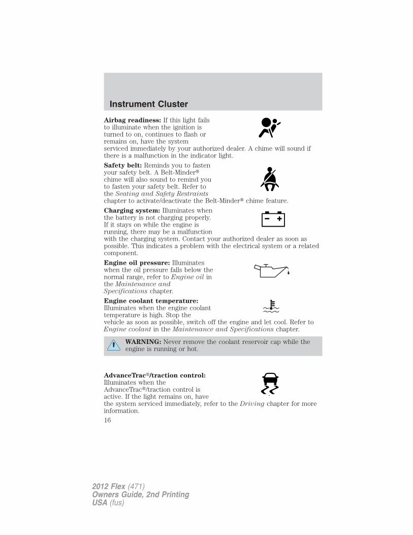
Airbag readiness: If this light failsto illuminate when the ignition isturned to on, continues to flash orremains on, have the systemserviced immediately by your authorized dealer. A chime will sound ifthere is a malfunction in the indicator light.
Safety belt: Reminds you to fastenyour safety belt. A Belt-Minder�chime will also sound to remind youto fasten your safety belt. Refer tothe Seating and Safety Restraintschapter to activate/deactivate the Belt-Minder� chime feature.
Charging system: Illuminates whenthe battery is not charging properly.If it stays on while the engine isrunning, there may be a malfunctionwith the charging system. Contact your authorized dealer as soon aspossible. This indicates a problem with the electrical system or a relatedcomponent.
Engine oil pressure: Illuminateswhen the oil pressure falls below thenormal range, refer to Engine oil inthe Maintenance andSpecifications chapter.
Engine coolant temperature:Illuminates when the engine coolanttemperature is high. Stop thevehicle as soon as possible, switch off the engine and let cool. Refer toEngine coolant in the Maintenance and Specifications chapter.
WARNING: Never remove the coolant reservoir cap while theengine is running or hot.
AdvanceTrac�/traction control:Illuminates when theAdvanceTrac�/traction control isactive. If the light remains on, havethe system serviced immediately, refer to the Driving chapter for moreinformation.
Instrument Cluster
16
2012 Flex (471)Owners Guide, 2nd PrintingUSA (fus)
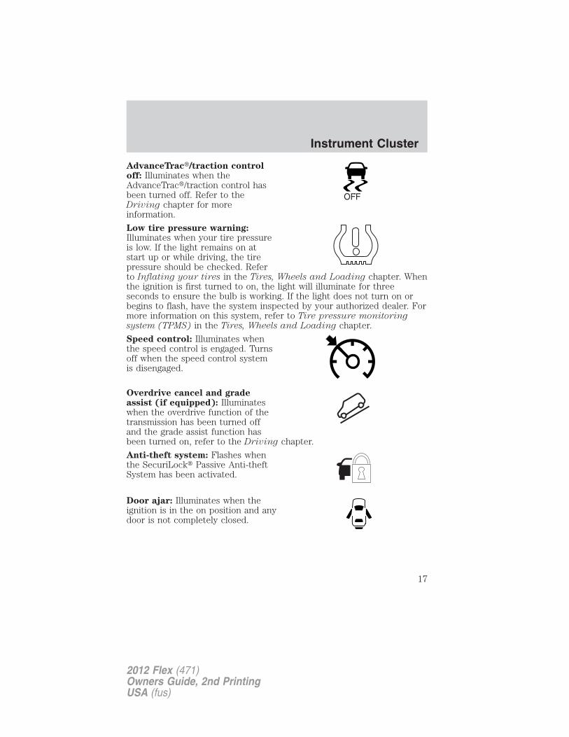
AdvanceTrac�/traction controloff: Illuminates when theAdvanceTrac�/traction control hasbeen turned off. Refer to theDriving chapter for moreinformation.
Low tire pressure warning:Illuminates when your tire pressureis low. If the light remains on atstart up or while driving, the tirepressure should be checked. Referto Inflating your tires in the Tires, Wheels and Loading chapter. Whenthe ignition is first turned to on, the light will illuminate for threeseconds to ensure the bulb is working. If the light does not turn on orbegins to flash, have the system inspected by your authorized dealer. Formore information on this system, refer to Tire pressure monitoringsystem (TPMS) in the Tires, Wheels and Loading chapter.
Speed control: Illuminates whenthe speed control is engaged. Turnsoff when the speed control systemis disengaged.
Overdrive cancel and gradeassist (if equipped): Illuminateswhen the overdrive function of thetransmission has been turned offand the grade assist function hasbeen turned on, refer to the Driving chapter.
Anti-theft system: Flashes whenthe SecuriLock� Passive Anti-theftSystem has been activated.
Door ajar: Illuminates when theignition is in the on position and anydoor is not completely closed.
OFF
Instrument Cluster
17
2012 Flex (471)Owners Guide, 2nd PrintingUSA (fus)
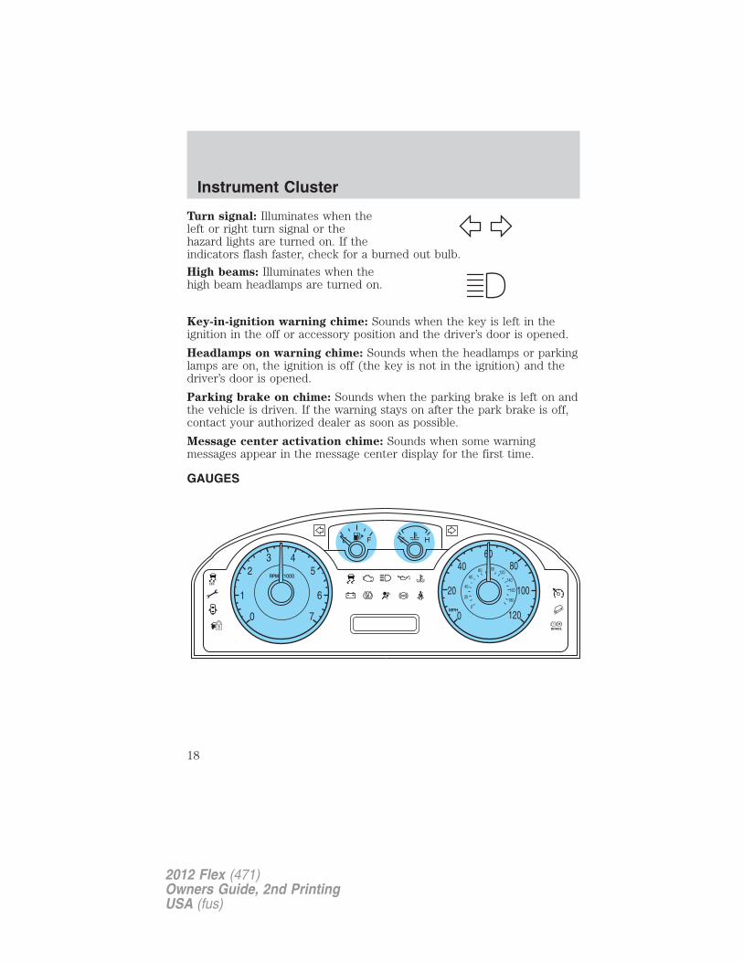
Turn signal: Illuminates when theleft or right turn signal or thehazard lights are turned on. If theindicators flash faster, check for a burned out bulb.
High beams: Illuminates when thehigh beam headlamps are turned on.
Key-in-ignition warning chime: Sounds when the key is left in theignition in the off or accessory position and the driver’s door is opened.
Headlamps on warning chime: Sounds when the headlamps or parkinglamps are on, the ignition is off (the key is not in the ignition) and thedriver’s door is opened.
Parking brake on chime: Sounds when the parking brake is left on andthe vehicle is driven. If the warning stays on after the park brake is off,contact your authorized dealer as soon as possible.
Message center activation chime: Sounds when some warningmessages appear in the message center display for the first time.
GAUGES
Instrument Cluster
18
2012 Flex (471)Owners Guide, 2nd PrintingUSA (fus)
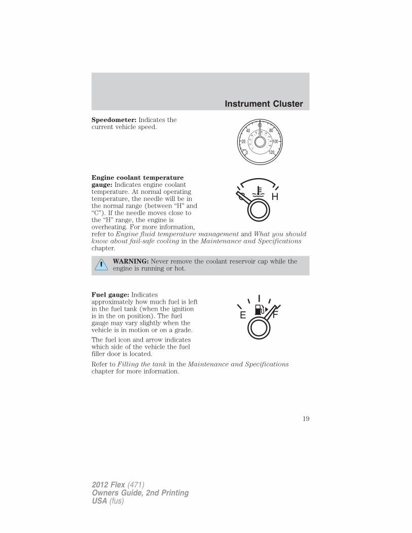
Speedometer: Indicates thecurrent vehicle speed.
Engine coolant temperaturegauge: Indicates engine coolanttemperature. At normal operatingtemperature, the needle will be inthe normal range (between “H” and“C”). If the needle moves close tothe “H” range, the engine isoverheating. For more information,refer to Engine fluid temperature management and What you shouldknow about fail-safe cooling in the Maintenance and Specificationschapter.
WARNING: Never remove the coolant reservoir cap while theengine is running or hot.
Fuel gauge: Indicatesapproximately how much fuel is leftin the fuel tank (when the ignitionis in the on position). The fuelgauge may vary slightly when thevehicle is in motion or on a grade.
The fuel icon and arrow indicateswhich side of the vehicle the fuelfiller door is located.
Refer to Filling the tank in the Maintenance and Specificationschapter for more information.
Instrument Cluster
19
2012 Flex (471)Owners Guide, 2nd PrintingUSA (fus)
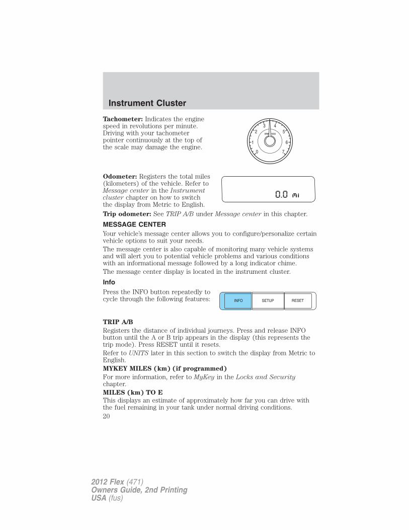
Tachometer: Indicates the enginespeed in revolutions per minute.Driving with your tachometerpointer continuously at the top ofthe scale may damage the engine.
Odometer: Registers the total miles(kilometers) of the vehicle. Refer toMessage center in the Instrumentcluster chapter on how to switchthe display from Metric to English.
Trip odometer: See TRIP A/B under Message center in this chapter.
MESSAGE CENTERYour vehicle’s message center allows you to configure/personalize certainvehicle options to suit your needs.The message center is also capable of monitoring many vehicle systemsand will alert you to potential vehicle problems and various conditionswith an informational message followed by a long indicator chime.The message center display is located in the instrument cluster.
InfoPress the INFO button repeatedly tocycle through the following features:
TRIP A/B
Registers the distance of individual journeys. Press and release INFObutton until the A or B trip appears in the display (this represents thetrip mode). Press RESET until it resets.Refer to UNITS later in this section to switch the display from Metric toEnglish.MYKEY MILES (km) (if programmed)
For more information, refer to MyKey in the Locks and Securitychapter.MILES (km) TO E
This displays an estimate of approximately how far you can drive withthe fuel remaining in your tank under normal driving conditions.
Instrument Cluster
20
2012 Flex (471)Owners Guide, 2nd PrintingUSA (fus)
Remember to turn the ignition off when refueling to allow this feature tocorrectly detect the added fuel.LOW FUEL LEVEL will display when you have approximately 50 miles(80 km), to empty. Press RESET to clear this warning message. It willreturn at approximately 25 miles (40 km), 10 miles (16 km) and 0 miles(0 km) miles to empty.Distance to empty is calculated using a running average fuel economy,which is based on your recent driving history of 500 miles (800 km).This value is not the same as the average fuel economy display. Therunning average fuel economy is re-initialized to a factory default value ifthe battery is disconnected.AVG MPG (L/100 km)
Average fuel economy displays your average fuel economy in miles/gallonor liters/100 km.If you calculate your average fuel economy by dividing distance traveledby gallons of fuel used (liters of fuel used by 100 kilometers traveled),your figure may be different than displayed for the following reasons:• Your vehicle was not perfectly level during fill-up• Differences in the automatic shut-off points on the fuel pumps at
service stations• Variations in top-off procedure from one fill-up to another
• Rounding of the displayed values to the nearest 0.1 gallon (liter)
To determine your average highway fuel economy, do the following:
1. Drive the vehicle at least 5 miles (8 km) with the speed controlsystem engaged to display a stabilized average.
2. Record the highway fuel economy for future reference.
It is important to press RESET (press RESET in order to reset thefunction) after setting the speed control to get accurate highway fueleconomy readings.
For more information refer to Essentials of good fuel economy in theMaintenance and Specifications chapter.
MPG (L/km)
This displays instantaneous fuel economy as a bar graph ranging from ↓poor economy to ↑ excellent economy.
Your vehicle must be moving to calculate instantaneous fuel economy.When your vehicle is not moving, this function shows ↓, one or no barsilluminated. Instantaneous fuel economy cannot be reset.
Instrument Cluster
21
2012 Flex (471)Owners Guide, 2nd PrintingUSA (fus)
TIMER
Timer displays the trip elapsed drive time.To operate, do the following:1. Press and release RESET in order to start the timer.2. Press and release RESET to pause the timer.3. Press and hold RESET until the timer resets.Blank Screen
The message center display will be blank after cycling through all of theinfo menu items.
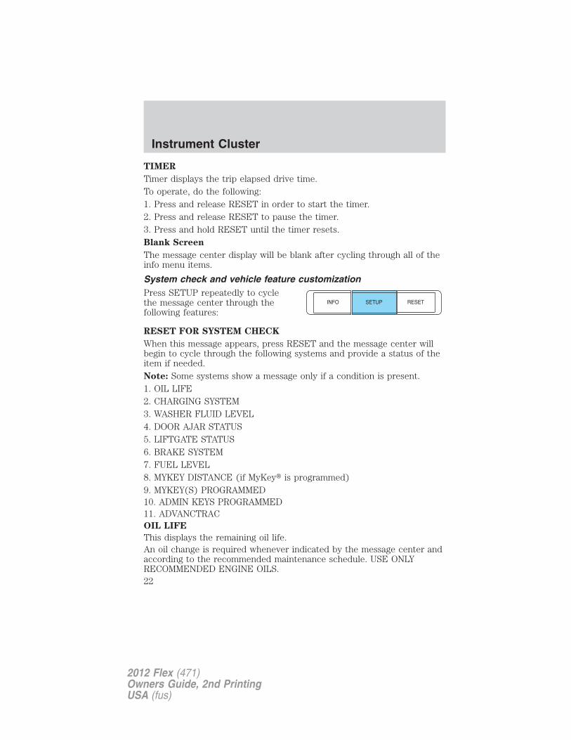
System check and vehicle feature customizationPress SETUP repeatedly to cyclethe message center through thefollowing features:
RESET FOR SYSTEM CHECK
When this message appears, press RESET and the message center willbegin to cycle through the following systems and provide a status of theitem if needed.Note: Some systems show a message only if a condition is present.1. OIL LIFE2. CHARGING SYSTEM3. WASHER FLUID LEVEL4. DOOR AJAR STATUS5. LIFTGATE STATUS6. BRAKE SYSTEM7. FUEL LEVEL8. MYKEY DISTANCE (if MyKey� is programmed)9. MYKEY(S) PROGRAMMED10. ADMIN KEYS PROGRAMMED11. ADVANCTRACOIL LIFE
This displays the remaining oil life.An oil change is required whenever indicated by the message center andaccording to the recommended maintenance schedule. USE ONLYRECOMMENDED ENGINE OILS.
Instrument Cluster
22
2012 Flex (471)Owners Guide, 2nd PrintingUSA (fus)
To reset the oil monitoring system to 100% after each oil change,perform the following:1. Press and release SETUP to display “OIL LIFE XXX% HOLD RESET =NEW”.2. Press and hold RESET for two seconds and release to reset the oil lifeto 100%.UNITS
Displays the current units in English or Metric.
Press RESET to change between English and Metric.
AUTOLAMP
This feature keeps your headlights on for up to three minutes after theignition is switched off.
Press RESET to select the new autolamp delay values of 0, 10, 20, 30,60, 90, 120 or 180 seconds.
AUTOLOCK
This feature automatically locks all vehicle doors when the vehicle isshifted into any gear, putting the vehicle in motion.
Press RESET to turn it off or on.
AUTOUNLOCK
This feature automatically unlocks all vehicle doors when the driver’sdoor is opened within 10 minutes of the ignition being turned off.
Press RESET to turn it off or on.
POWER LIFTGATE (if equipped)
This feature allows users to open/close the rear liftgate at the touch of abutton.
Press RESET to turn it off or on.
EASY ENTRY
This feature automatically moves the driver’s seat backwards for easyexit/entry from the vehicle.
Press RESET to turn it off or on.
REAR PARK AID (if equipped)
This feature sounds a tone to warn the driver of obstacles near the rearbumper, and functions only when R (Reverse) gear is selected.
Press RESET to turn it off or on.
Instrument Cluster
23
2012 Flex (471)Owners Guide, 2nd PrintingUSA (fus)
TRAILER SWAY (if equipped)
This feature uses the electronic stability control to mitigate trailer sway,Press RESET to turn it off or on.CREATE MYKEY / MYKEY SETUP / CLEAR MYKEY
For more information refer to MyKey in the Locks and Securitychapter.LANGUAGE = ENGLISH / SPANISH / FRENCH
Allows you to choose which language the message center will display in.Selectable languages are English, Spanish, or French.Waiting four seconds or pressing the RESET button cycles the messagecenter through each of the language choices.Press and hold RESET for two seconds to set the language choice.
System warningsSystem warnings alert you to possible problems or malfunctions in yourvehicle’s operating systems.In the event of a multiple warning situation, the message center willcycle the display to show all warnings by displaying each one for fourseconds.The message center will display the last selected feature if there are nomore warning messages.
Types of messages and warnings:
• Some messages will appear briefly to inform you of something youmay need to take action on or be informed of.
• Some messages will appear once and then again when the vehicle isrestarted.
• Some messages will reappear after clearing or being reset if a problemor condition is still present and needs your attention.
• Some messages can be acknowledged and reset by pressing RESET.This allows you to use the full message center functionality by clearingthe message.
DRIVER DOOR AJAR — Displayed when the driver door is notcompletely closed.
PASSENGER DOOR AJAR — Displayed when the passenger door isnot completely closed.
REAR LEFT DOOR AJAR — Displayed when the rear left door is notcompletely closed.
Instrument Cluster
24
2012 Flex (471)Owners Guide, 2nd PrintingUSA (fus)
REAR RIGHT DOOR AJAR — Displayed when the rear right door isnot completely closed.PARK BRAKE ENGAGED — Displayed when the parking brake is set,the engine is running and the vehicle is driven more than 3 mph(5 km/h). If the warning stays on after the parking brake is released,contact your authorized dealer as soon as possible.XXX MILES TO E FUEL LEVEL LOW — Displayed as an earlyreminder of a low fuel condition.CHECK FUEL FILL INLET — Displayed when the fuel fill inlet maynot be properly closed. Refer to Easy Fuel “no cap” fuel system in theMaintenance and Specifications chapter.CHECK BRAKE SYSTEM — Displayed when the braking system is notoperating properly. If the warning stays on or continues to come on,contact your authorized dealer as soon as possible.LIFTGATE AJAR — Displayed when the liftgate is not completelyclosed. Press RESET to reset display.CHECK PARK AID (if equipped) — Displayed when the transmissionis in R (Reverse) and the reverse sensing system (park aid) is disabled.REMOVE OBJECTS NEAR PASS SEAT — Displayed when objectsare by the passenger seat. After the objects are moved away from theseat, if the warning stays on or continues to come on, contact yourauthorized dealer as soon as possible.BRAKE FLUID LEVEL LOW — Indicates the brake fluid level is lowand the brake system should be inspected immediately. Refer to Brakefluid in the Maintenance and Specifications chapter.AWD OFF (if equipped) — Displayed when the AWD system has beenautomatically disabled to protect itself. This is caused by operating thevehicle with the compact spare tire installed or if the system isoverheating. The AWD system will resume normal function and clear thismessage after driving a short distance with the road tire re-installed orafter the system is allowed to cool.
CHECK AWD (if equipped) — Displayed when a problem exists withthe AWD system. Contact your authorized dealer as soon as possible.
LOW TIRE PRESSURE — Displayed when one or more tires on yourvehicle has low tire pressure. Refer to Inflating your tires in the Tires,Wheels and Loading chapter.
TIRE PRESSURE MONITOR FAULT — Displayed when the TirePressure Monitoring System is malfunctioning. If the warning stays on orcontinues to come on, contact your authorized dealer as soon aspossible.
Instrument Cluster
25
2012 Flex (471)Owners Guide, 2nd PrintingUSA (fus)
TIRE PRESSURE SENSOR FAULT — Displayed when a tire pressuresensor is malfunctioning, or your spare tire is in use. For moreinformation on how the system operates under these conditions, refer toTire Pressure Monitoring System (TPMS) in the Tires, Wheels andLoading chapter. If the warning stays on or continues to come on,contact your authorized dealer as soon as possible.POWER STEERING ASSIST FAULT — The power steering systemhas disabled power steering assist due to a system error; service isrequired.SERVICE POWER STEERING — The power steering system hasdetected a condition that requires service.
SERVICE POWER STEERING NOW — The power steering systemhas detected a condition that requires service immediately.
ENGINE OIL CHANGE SOON — Displayed when the engine oil liferemaining is 5% to 1%.
OIL CHANGE REQUIRED — Displayed when the oil life left reaches0%.
INTKEY COULD NOT PROGRAM — Displayed when an attempt ismade to program a fifth integrated key to the remote key entry system.For more information on integrated key, refer to the Locks and Securitychapter in this manual.
ADVANCETRAC OFF — Displayed briefly when the system has beendisabled.
ADVANCETRAC ON — Displayed briefly when the system has beenenabled.
TRACTION CONTROL ON — Displayed briefly when the system hasbeen enabled.
TRACTION CONTROL OFF — Displayed briefly when the system hasbeen disabled.
TRAILER SWAY REDUCE SPEED (if equipped) — Displayed whenthe trailer sway control has detected trailer sway. For more information,refer to the Driving chapter for more information.
ACTIVE PARK FAULT (if equipped) — Displayed when a fault hasoccurred with the active park assist system. Refer to Active park assistin the Driving chapter for more information.
ACTIVE PARK CANCELLED (if equipped) — Displayed when theactive park assist feature has been canceled when it is in use. Refer toActive park assist in the Driving chapter for more information.
Instrument Cluster
26
2012 Flex (471)Owners Guide, 2nd PrintingUSA (fus)
CANCELLED BY OVER SPEED (if equipped)— Displayed when theactive park assist feature self cancels due to vehicle speed over thepreset limit allowed by the active park assist system. Refer to Activepark assist in the Driving chapter for more information.
CANCELLED BY DRIVER INPUT (if equipped) — Displayed whenthe autopark feature has been canceled due to driver inputs. Refer toActive park assist in the Driving chapter for more information.
CANCELLED BY ADV TRAC EVENT (if equipped) — Displayedwhen the active park feature has been canceled due to theAdvanceTrac� system activating. Refer to Active park assist in theDriving chapter for more information.
CANCELLED BY ABS EVENT (if equipped) — Displayed when theactive park feature has been canceled due to the ABS activating. Refer toActive park assist in the Driving chapter for more information.
ACTIVE PARK REDUCE SPEED (if equipped) — May display whenusing the active park assist system. See Active park assist in theDriving chapter for more information.
ACTIVE PARK SEARCHING (if equipped) — May display whenusing the active park assist system. See Active park assist in theDriving chapter for more information.
SPACE FOUND PULL FORWARD (if equipped) — May display whenusing the active park assist system. See Active park assist in theDriving chapter for more information.
SPACE FOUND STOP (if equipped) — May display when using theactive park assist system. See Active park assist in the Driving chapterfor more information.
PULL FORWARD USE CAUTION (if equipped) — May display whenusing the active park assist system. See Active park assist in theDriving chapter for more information.
BACK UP SLOWLY USE CAUTION (if equipped) — May displaywhen using the active park assist system. See Active park assist in theDriving chapter for more information.
BACK UP USE CAUTION (if equipped) — May display when usingthe active park assist system. See Active park assist in the Drivingchapter for more information.
ACTIVE PARK FINISHED (if equipped) — May display when usingthe active park assist system. See Active park assist in the Drivingchapter for more information.
Instrument Cluster
27
2012 Flex (471)Owners Guide, 2nd PrintingUSA (fus)
REMOVE HANDS PUT IN REVERSE (if equipped) — May displaywhen using the active park assist system. See Active park assist in theDriving chapter for more information.ACTIVE PARK NOT AVAILABLE (if equipped) — May display whenusing the active park assist system. See Active park assist in theDriving chapter for more information.ACTIVE PARK DEACTIVATED (if equipped) — Displayed when theactive park feature has been turned off. Refer to Active park assist inthe Driving chapter for more information.MYKEY ACTIVE DRIVE SAFELY — Displayed at startup when MyKeyis in use. Refer to MyKey in the Locks and Security chapter for moreinformation.KEY COULD NOT PROGRAM — Displayed when an attempt is madeto program a spare key using two existing MyKeys. Refer to MyKey inthe Locks and Security chapter for more information.VEHICLE SPEED 80 MPH MAX — Displayed when a MyKey is in useand the admin has enabled the MyKey speed limit and the vehicle speedis 80 mph (130 km/h). Refer to MyKey in the Locks and Securitychapter for more information.SPEED LIMITED TO 80 MPH — Displayed when starting the vehicleand MyKey is in use and the MyKey speed limit is on. Refer to MyKey inthe Locks and Security chapter for more information.CHECK SPEED DRIVE SAFELY — Displayed when a MyKey is in useand the optional setting is on and the vehicle exceeds a preselectedspeed. Refer to MyKey in the Locks and Security chapter for moreinformation.VEHICLE NEAR TOP SPEED — Displayed when a MyKey is in useand the MyKey speed limit is on and the vehicle speed is approaching80 mph (130 km/h). Refer to MyKey in the Locks and Security chapterfor more information.TOP SPEED MYKEY SETTING — Displayed when a MyKey is in useand the MyKey speed limit is on and the vehicle speed is 80 mph(130 km/h). Refer to MyKey in the Locks and Security chapter for moreinformation.BUCKLE UP TO UNMUTE AUDIO — Displayed when a MyKey is inuse and Belt-Minder� is activated. Refer to MyKey in the Locks andSecurity chapter for more information.
ADVTRAC ON MYKEY SETTING — Displayed when a MyKey is inuse when trying to disable the AdvanceTrac� system and the optionalsetting is on. Refer to MyKey in the Locks and Security chapter formore information.
Instrument Cluster
28
2012 Flex (471)Owners Guide, 2nd PrintingUSA (fus)
SERVICE ADVANCETRAC — Displayed when the AdvanceTrac�system has detected a condition that requires service.
TO STOP ALARM START VEHICLE — Displayed when the perimeteralarm system is armed and the vehicle is entered using the key on thedriver’s side door. In order to prevent the perimeter alarm system fromtriggering, the ignition must be turned to start or on with a valid keybefore the 12-second chime expires. See Perimeter alarm system in theLocks and Security chapter.
POWER REDUCED TO LOWER TEMP — Displayed when vehicleperformance is reduced due to high engine fluid temperatures. SeeEngine fluid temperature management and What you should knowabout fail-safe cooling in the Maintenance and Specifications chapter.
Instrument Cluster
29
2012 Flex (471)Owners Guide, 2nd PrintingUSA (fus)
AUDIO SYSTEMS
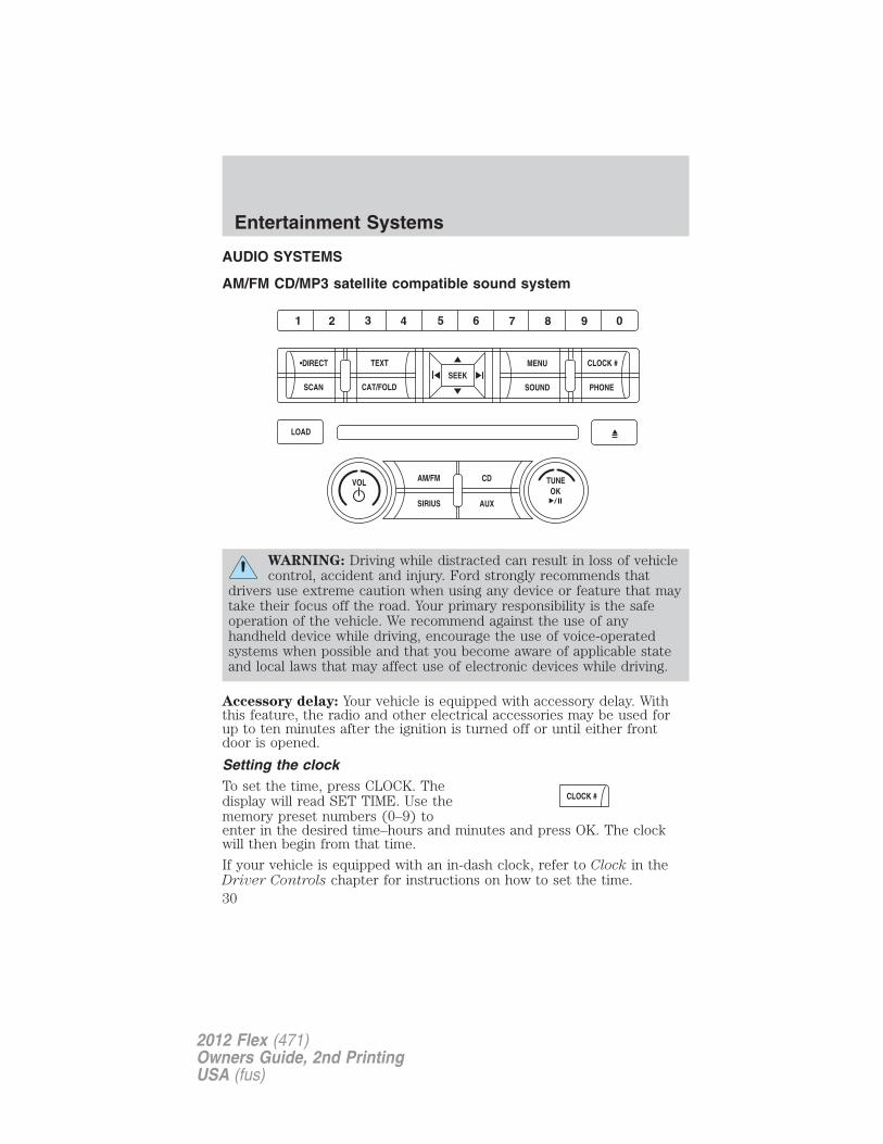
AM/FM CD/MP3 satellite compatible sound system
WARNING: Driving while distracted can result in loss of vehiclecontrol, accident and injury. Ford strongly recommends that
drivers use extreme caution when using any device or feature that maytake their focus off the road. Your primary responsibility is the safeoperation of the vehicle. We recommend against the use of anyhandheld device while driving, encourage the use of voice-operatedsystems when possible and that you become aware of applicable stateand local laws that may affect use of electronic devices while driving.
Accessory delay: Your vehicle is equipped with accessory delay. Withthis feature, the radio and other electrical accessories may be used forup to ten minutes after the ignition is turned off or until either frontdoor is opened.
Setting the clockTo set the time, press CLOCK. Thedisplay will read SET TIME. Use thememory preset numbers (0–9) toenter in the desired time–hours and minutes and press OK. The clockwill then begin from that time.
If your vehicle is equipped with an in-dash clock, refer to Clock in theDriver Controls chapter for instructions on how to set the time.
Entertainment Systems
30
2012 Flex (471)Owners Guide, 2nd PrintingUSA (fus)
Note: If your vehicle is equipped with a navigation system, refer toSetting the clock in your Navigation supplement.
AM/FM Radio
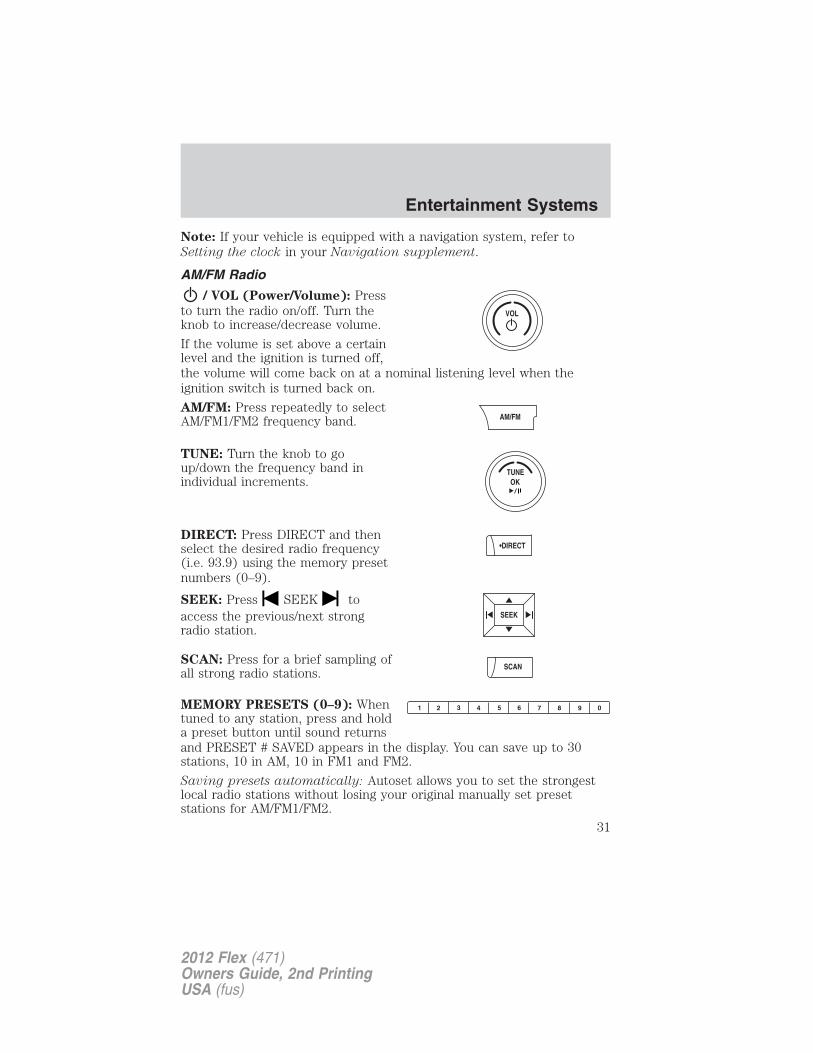
/ VOL (Power/Volume): Pressto turn the radio on/off. Turn theknob to increase/decrease volume.
If the volume is set above a certainlevel and the ignition is turned off,the volume will come back on at a nominal listening level when theignition switch is turned back on.
AM/FM: Press repeatedly to selectAM/FM1/FM2 frequency band.
TUNE: Turn the knob to goup/down the frequency band inindividual increments.
DIRECT: Press DIRECT and thenselect the desired radio frequency(i.e. 93.9) using the memory presetnumbers (0–9).
SEEK: Press SEEK toaccess the previous/next strongradio station.
SCAN: Press for a brief sampling ofall strong radio stations.
MEMORY PRESETS (0–9): Whentuned to any station, press and holda preset button until sound returnsand PRESET # SAVED appears in the display. You can save up to 30stations, 10 in AM, 10 in FM1 and FM2.
Saving presets automatically: Autoset allows you to set the strongestlocal radio stations without losing your original manually set presetstations for AM/FM1/FM2.
Entertainment Systems
31
2012 Flex (471)Owners Guide, 2nd PrintingUSA (fus)
To activate the autoset feature: Press MENU repeatedly until AUTOPRESET ON/OFF appears in the display. Use SEEK to switchAUTO PRESET to ON, and either wait five seconds for the search toinitiate or press OK to immediately initiate the search. If you pressanother control within those five seconds, the search will not initiate.The 10 strongest stations will be filled and the station stored in preset 1will begin playing.
If there are fewer than 10 strong stations, the system will store the lastone in the remaining presets.
RDS Radio
Available only in FM mode. This feature allows you to searchRDS-equipped stations for a certain category of music format: CLASSIC,COUNTRY, JAZZ/RB, ROCK, etc.
To activate: Press MENU repeatedly until RDS (ON/OFF) appears in thedisplay. Use SEEK to switch RDS ON/OFF. When RDS is OFF,you will not be able to search for RDS equipped stations or view thestation name or type.
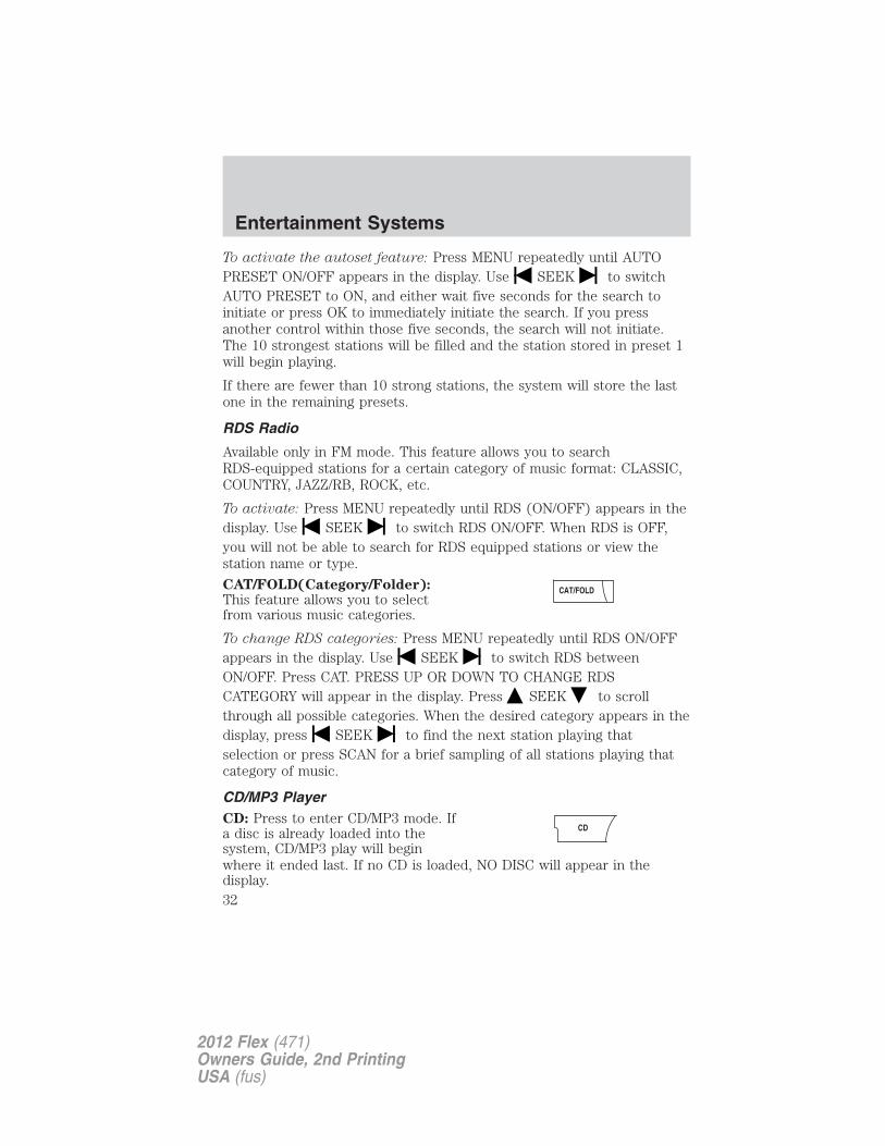
CAT/FOLD(Category/Folder):This feature allows you to selectfrom various music categories.
To change RDS categories: Press MENU repeatedly until RDS ON/OFFappears in the display. Use SEEK to switch RDS betweenON/OFF. Press CAT. PRESS UP OR DOWN TO CHANGE RDSCATEGORY will appear in the display. Press SEEK to scrollthrough all possible categories. When the desired category appears in thedisplay, press SEEK to find the next station playing thatselection or press SCAN for a brief sampling of all stations playing thatcategory of music.
CD/MP3 PlayerCD: Press to enter CD/MP3 mode. Ifa disc is already loaded into thesystem, CD/MP3 play will beginwhere it ended last. If no CD is loaded, NO DISC will appear in thedisplay.
Entertainment Systems
32
2012 Flex (471)Owners Guide, 2nd PrintingUSA (fus)
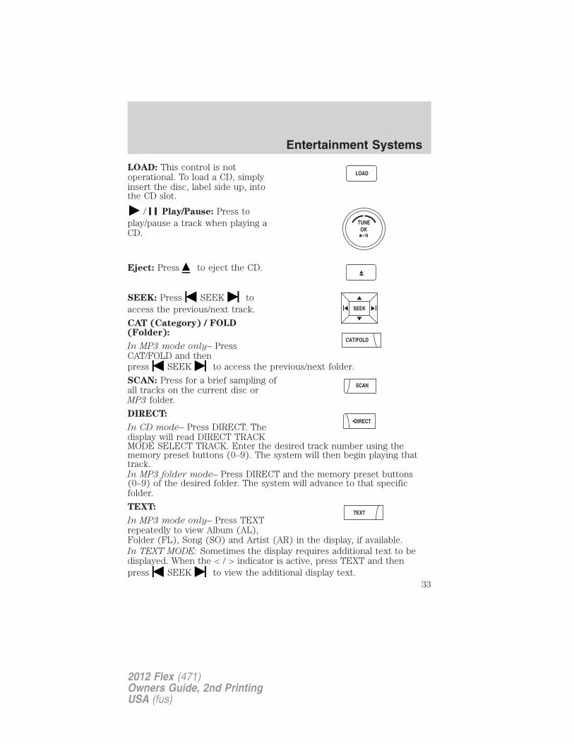
LOAD: This control is notoperational. To load a CD, simplyinsert the disc, label side up, intothe CD slot.
/ Play/Pause: Press toplay/pause a track when playing aCD.
Eject: Press to eject the CD.
SEEK: Press SEEK toaccess the previous/next track.
CAT (Category) / FOLD(Folder):
In MP3 mode only– PressCAT/FOLD and thenpress SEEK to access the previous/next folder.
SCAN: Press for a brief sampling ofall tracks on the current disc orMP3 folder.
DIRECT:
In CD mode– Press DIRECT. Thedisplay will read DIRECT TRACKMODE SELECT TRACK. Enter the desired track number using thememory preset buttons (0–9). The system will then begin playing thattrack.In MP3 folder mode– Press DIRECT and the memory preset buttons(0–9) of the desired folder. The system will advance to that specificfolder.
TEXT:
In MP3 mode only– Press TEXTrepeatedly to view Album (AL),Folder (FL), Song (SO) and Artist (AR) in the display, if available.In TEXT MODE: Sometimes the display requires additional text to bedisplayed. When the < / > indicator is active, press TEXT and thenpress SEEK to view the additional display text.
Entertainment Systems
33
2012 Flex (471)Owners Guide, 2nd PrintingUSA (fus)
COMPRESSION: Press MENU repeatedly until COMPRESSION ON/OFFappears in the display. Use SEEK to switch between ON/OFF.When COMPRESSION is ON, the system will bring the soft and loud CDpassages together for a more consistent listening level.SHUFFLE: Press MENU repeatedly until SHUFFLE ON/OFF appears inthe display. Use SEEK to switch between ON/OFF. If you wish to
engage shuffle mode right away, press SEEK to begin randomplay. Otherwise, random play will begin when the current track isfinished playing. The system will only shuffle the disc currently playing.
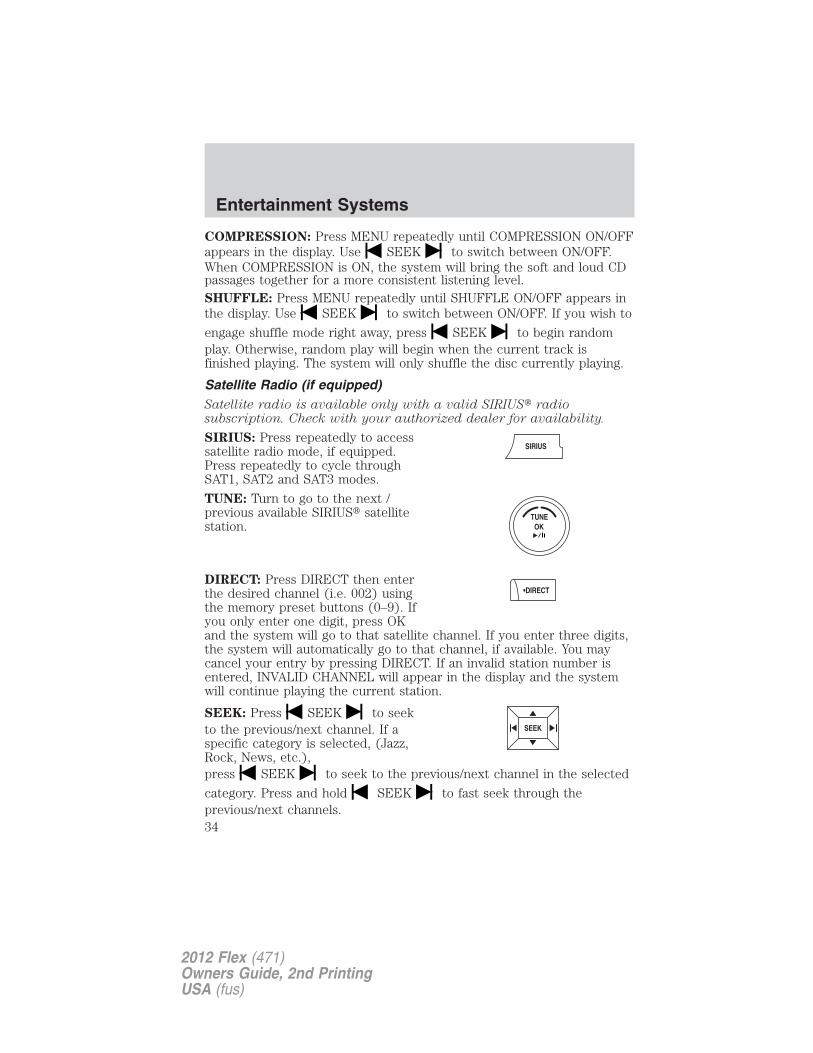
Satellite Radio (if equipped)Satellite radio is available only with a valid SIRIUS� radiosubscription. Check with your authorized dealer for availability.
SIRIUS: Press repeatedly to accesssatellite radio mode, if equipped.Press repeatedly to cycle throughSAT1, SAT2 and SAT3 modes.
TUNE: Turn to go to the next /previous available SIRIUS� satellitestation.
DIRECT: Press DIRECT then enterthe desired channel (i.e. 002) usingthe memory preset buttons (0–9). Ifyou only enter one digit, press OKand the system will go to that satellite channel. If you enter three digits,the system will automatically go to that channel, if available. You maycancel your entry by pressing DIRECT. If an invalid station number isentered, INVALID CHANNEL will appear in the display and the systemwill continue playing the current station.
SEEK: Press SEEK to seekto the previous/next channel. If aspecific category is selected, (Jazz,Rock, News, etc.),press SEEK to seek to the previous/next channel in the selected
category. Press and hold SEEK to fast seek through theprevious/next channels.
Entertainment Systems
34
2012 Flex (471)Owners Guide, 2nd PrintingUSA (fus)
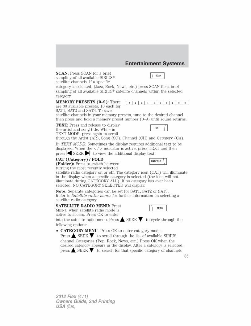
SCAN: Press SCAN for a briefsampling of all available SIRIUS�satellite channels. If a specificcategory is selected, (Jazz, Rock, News, etc.) press SCAN for a briefsampling of all available SIRIUS� satellite channels within the selectedcategory.
MEMORY PRESETS (0–9): Thereare 30 available presets, 10 each forSAT1, SAT2 and SAT3. To savesatellite channels in your memory presets, tune to the desired channelthen press and hold a memory preset number (0–9) until sound returns.
TEXT: Press and release to displaythe artist and song title. While inTEXT MODE, press again to scrollthrough the Artist (AR), Song (SO), Channel (CH) and Category (CA).
In TEXT MODE: Sometimes the display requires additional text to bedisplayed. When the < / > indicator is active, press TEXT and thenpress SEEK to view the additional display text.
CAT (Category) / FOLD(Folder): Press to switch betweenturning the most recently selectedsatellite radio category on or off. The category icon (CAT) will illuminatein the display when a specific category is selected (the icon will notilluminate during CATEGORY ALL). If no category has ever beenselected, NO CATEGORY SELECTED will display.
Note: Separate categories can be set for SAT1, SAT2 or SAT3.Refer to Satellite radio menu for further information on selecting asatellite radio category.
SATELLITE RADIO MENU: PressMENU when satellite radio mode isactive to access. Press OK to enterinto the satellite radio menu. Press SEEK to cycle through thefollowing options:
• CATEGORY MENU- Press OK to enter category mode.Press SEEK to scroll through the list of available SIRIUSchannel Categories (Pop, Rock, News, etc.) Press OK when thedesired category appears in the display. After a category is selected,press SEEK to search for that specific category of channels
Entertainment Systems
35
2012 Flex (471)Owners Guide, 2nd PrintingUSA (fus)
only (i.e. ROCK). You may also select CATEGORY ALL to seek allavailable SIRIUS categories and channels. Press OK to close andreturn to the main menu.
• SONG SEEK MENU- Press OK to enter song seek menu.Press SEEK to scroll through the following options:a. SAVE THIS SONG: Press OK to save the currently playing song’stitle in the system’s memory. (If you try to save something other thana song, CANNOT SAVE will appear in the display.) When the chosensong is playing on any satellite radio channel, the system will alert youwith an audible prompt. Press OK while SONG ALERT is in thedisplay and the system will take you to the channel playing thedesired song. You can save up to 20 song titles. If you attempt to savemore than 20 titles, the display will read REPLACE SONG? Press OKto access the saved titles and press SEEK to cycle through thesaved titles. When the song title appears in the display that you wouldlike to replace, press OK. SONG REPLACED will appear in the display.b. DELETE A SONG: Press OK to delete a song from the system’smemory. Press SEEK to cycle through the saved songs. Whenthe song appears in the display that you would like to delete, pressOK. The song will appear in the display for confirmation. Press OKagain and the display will read SONG DELETED. If you do not wantto delete the currently listed song, press SEEK to select eitherRETURN or CANCEL.Note: If there are no songs presently saved, the display will read NOSONGS.c. DELETE ALL SONGS: Press OK to delete all song’s from thesystem’s memory. The display will read ARE YOU SURE ? Press OK toconfirm deletion of all saved songs and the display will read ALLDELETED.Note: If there are no songs presently saved, the display will read NOSONGS.d. DISABLE ALERTS/ENABLE ALERTS: Press OK toenable/disable the satellite alert status which alerts you when yourselected songs are playing on a satellite radio channel. (The systemdefault is disabled.) SONG ALERTS ENABLED/DISABLED will appearin the display. The menu listing will display the opposite state. Forexample, if you have chosen to enable the song alerts, the menulisting will read DISABLE as the alerts are currently on, so your otheroption is to turn them off.
Entertainment Systems
36
2012 Flex (471)Owners Guide, 2nd PrintingUSA (fus)
• CHANNEL LOCKOUT MENU- Press OK to enter the ChannelLockout menu. Press the SEEK to scroll through the followingoptions:a. LOCK/UNLOCK THIS CHANNEL: Press OK whenLOCK/UNLOCK THIS CHANNEL is displayed and the display will readENTER PIN. Enter your four-digit PIN number (initial PIN is 1234)and the system will lock/unlock the channel and CHANNEL LOCKEDor UNLOCKED will be displayed.Note: you must be tuned to the specific channel you want tolock/unlock when using this feature.b. CHANGE PIN: Press OK when CHANGE PIN is displayed. Thedisplay will read ENTER OLD PIN. Enter your current (old) PINnumber and when the system accepts your entry it will displayENTER NEW PIN. Enter your new four-digit PIN and the system willsave the new PIN and PIN SAVED will display.c. UNLOCK ALL CHANNELS: Press OK when UNLOCK ALLCHANNELS is displayed and the display will read ENTER PIN. Enteryour four-digit PIN and the system will unlock all channels and thedisplay will read CHANNEL UNLOCKED.d. RESET PIN: Press OK when RESET PIN is displayed. The displaywill read ARE YOU SURE. Press OK again to automatically reset thePIN number to its initial password setting (1234). PIN RESET TODEFAULT PIN will be displayed.e. RETURN: Press OK when RETURN is displayed and the systemwill exit back to the satellite radio menu.
Sound AdjustmentsPress SOUND repeatedly to cyclethrough the following features:
BASS: Press SEEK toadjust the level of bass.
TREBLE: Press SEEK to adjust the level of treble.
BALANCE: Press SEEK to adjust the audio between the left(L) and right (R) speakers.
FADE: Press SEEK to adjust the audio between the back (B)and front (F) speakers.
Entertainment Systems
37
2012 Flex (471)Owners Guide, 2nd PrintingUSA (fus)
SPEED COMPENSATED VOLUME: With this feature on, radio volumeautomatically gets louder with increasing vehicle speed to compensatefor road and wind noise.
The default setting is off.
Use SEEK to adjust between SPEED OFF and levels 1–7:
Increasing the level from 1 (lowest setting) to 7 (highest setting) allowsthe radio volume to automatically change slightly with vehicle speed tocompensate for road and wind noise.
Recommended level is 1–3; SPEED OFF turns the feature off and level 7is the maximum setting.
DSP MODE (if equipped)): Press SEEK to choose betweenSTEREO SURROUND mode and STEREO mode.
Extra FeaturesAUX: Press repeatedly to cyclethrough LINE (auxiliary audiomode), SYNC� (if equipped) andFES modes (if equipped).
For location and further information on auxiliary audio mode, refer toAuxiliary input jack later in this chapter.
If your vehicle is equipped with SYNC�, refer to the SYNC� informationincluded with your vehicle for further information.
/ Play/Pause:
In CD/DVD mode (if equipped)–When a CD or DVD is playing in thefamily entertainment system, pressthis control to play or pause thecurrent CD/DVD. The CD/DVD status will display in the radio display.
OK: Your vehicle may be equipped with special phone and mediafeatures which will require you to confirm commands by pressing OK.Refer to the SYNC information included with your vehicle for furtherinformation.
PHONE: If your vehicle is equipped with SYNC�, press to access SYNCPHONE features. Refer to the SYNC� information included with yourvehicle for further information.If your vehicle is not equipped with SYNC�, the display will read NOPHONE.
Entertainment Systems
38
2012 Flex (471)Owners Guide, 2nd PrintingUSA (fus)
Audio system–Navigation system based (if equipped)If your vehicle is equipped with the navigation system, it will have anintegrated navigation/audio system. See the Navigation systemsupplement for operating instructions on using this audio system.
Auxiliary input jack (Line in)
WARNING: Driving while distracted can result in loss of vehiclecontrol, accident and injury. Ford strongly recommends that
drivers use extreme caution when using any device or feature that maytake their focus off the road. Your primary responsibility is the safeoperation of the vehicle. We recommend against the use of anyhandheld device while driving, encourage the use of voice-operatedsystems when possible and that you become aware of applicable stateand local laws that may affect use of electronic devices while driving.
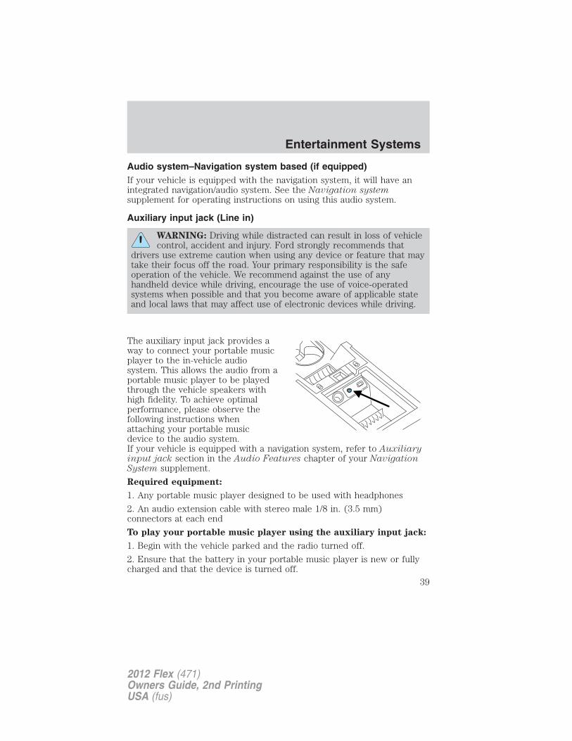
The auxiliary input jack provides away to connect your portable musicplayer to the in-vehicle audiosystem. This allows the audio from aportable music player to be playedthrough the vehicle speakers withhigh fidelity. To achieve optimalperformance, please observe thefollowing instructions whenattaching your portable musicdevice to the audio system.If your vehicle is equipped with a navigation system, refer to Auxiliaryinput jack section in the Audio Features chapter of your NavigationSystem supplement.
Required equipment:
1. Any portable music player designed to be used with headphones
2. An audio extension cable with stereo male 1/8 in. (3.5 mm)connectors at each end
To play your portable music player using the auxiliary input jack:
1. Begin with the vehicle parked and the radio turned off.
2. Ensure that the battery in your portable music player is new or fullycharged and that the device is turned off.
Entertainment Systems
39
2012 Flex (471)Owners Guide, 2nd PrintingUSA (fus)
3. Attach one end of the audio extension cable to the headphone outputof your player and the other end of the audio extension cable to the AIJin your vehicle.
4. Turn the radio on, using either a tuned FM station or a CD loaded intothe system. Adjust the volume to a comfortable listening level.
5. Turn the portable music player on and adjust the volume to 1/2 thevolume.
6. Press AUX on the vehicle radio repeatedly until LINE, LINE IN orSYNC LINE IN appears in the display.You should hear audio from your portable music player although it maybe low.
7. Adjust the sound on your portable music player until it reaches thelevel of the FM station or CD by switching back and forth between theAUX and FM or CD controls.
Troubleshooting:
1. Do not connect the audio input jack to a line level output. Line leveloutputs are intended for connection to a home stereo and are notcompatible with the AIJ. The AIJ will only work correctly with devicesthat have a headphone output with a volume control.
2. Do not set the portable music player’s volume level higher than isnecessary to match the volume of the CD or FM radio in your audiosystem as this will cause distortion and will reduce sound quality. Manyportable music players have different output levels, so not all playersshould be set at the same levels. Some players will sound best at fullvolume and others will need to be set at a lower volume.
3. If the music sounds distorted at lower listening levels, turn theportable music player volume down. If the problems persists, replace orrecharge the batteries in the portable music player.
4. The portable music player must be controlled in the same mannerwhen it is used with headphones as the AIJ does not provide control(play, pause, etc.) over the attached portable music player.
5. For safety reasons, connecting or adjusting the settings on yourportable music player should not be attempted while the vehicle ismoving. Also, the portable music player should be stored in a securelocation, such as the center console or the glove box, when the vehicle isin motion. The audio extension cable must be long enough to allow theportable music player to be safely stored while the vehicle is in motion.
Entertainment Systems
40
2012 Flex (471)Owners Guide, 2nd PrintingUSA (fus)
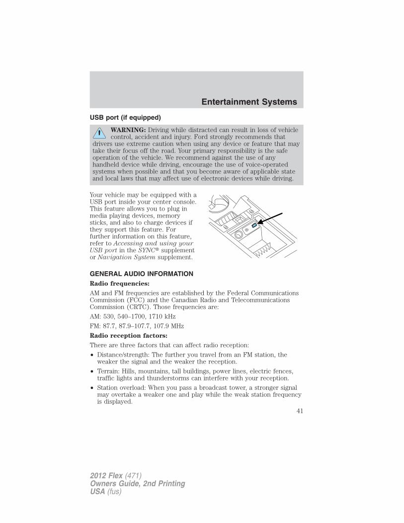
USB port (if equipped)
WARNING: Driving while distracted can result in loss of vehiclecontrol, accident and injury. Ford strongly recommends that
drivers use extreme caution when using any device or feature that maytake their focus off the road. Your primary responsibility is the safeoperation of the vehicle. We recommend against the use of anyhandheld device while driving, encourage the use of voice-operatedsystems when possible and that you become aware of applicable stateand local laws that may affect use of electronic devices while driving.
Your vehicle may be equipped with aUSB port inside your center console.This feature allows you to plug inmedia playing devices, memorysticks, and also to charge devices ifthey support this feature. Forfurther information on this feature,refer to Accessing and using yourUSB port in the SYNC� supplementor Navigation System supplement.
GENERAL AUDIO INFORMATIONRadio frequencies:
AM and FM frequencies are established by the Federal CommunicationsCommission (FCC) and the Canadian Radio and TelecommunicationsCommission (CRTC). Those frequencies are:
AM: 530, 540–1700, 1710 kHz
FM: 87.7, 87.9–107.7, 107.9 MHz
Radio reception factors:
There are three factors that can affect radio reception:
• Distance/strength: The further you travel from an FM station, theweaker the signal and the weaker the reception.
• Terrain: Hills, mountains, tall buildings, power lines, electric fences,traffic lights and thunderstorms can interfere with your reception.
• Station overload: When you pass a broadcast tower, a stronger signalmay overtake a weaker one and play while the weak station frequencyis displayed.
Entertainment Systems
41
2012 Flex (471)Owners Guide, 2nd PrintingUSA (fus)
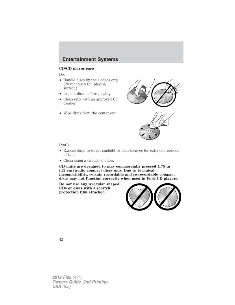
CD/CD player care
Do:
• Handle discs by their edges only.(Never touch the playingsurface).
• Inspect discs before playing.
• Clean only with an approved CDcleaner.
• Wipe discs from the center out.
Don’t:
• Expose discs to direct sunlight or heat sources for extended periodsof time.
• Clean using a circular motion.
CD units are designed to play commercially pressed 4.75 in(12 cm) audio compact discs only. Due to technicalincompatibility, certain recordable and re-recordable compactdiscs may not function correctly when used in Ford CD players.
Do not use any irregular shapedCDs or discs with a scratchprotection film attached.
Entertainment Systems
42
2012 Flex (471)Owners Guide, 2nd PrintingUSA (fus)
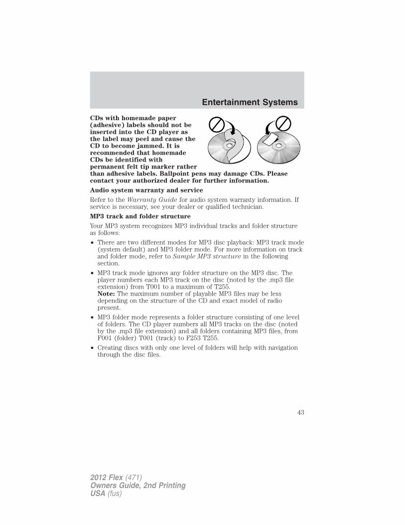
CDs with homemade paper(adhesive) labels should not beinserted into the CD player asthe label may peel and cause theCD to become jammed. It isrecommended that homemadeCDs be identified withpermanent felt tip marker ratherthan adhesive labels. Ballpoint pens may damage CDs. Pleasecontact your authorized dealer for further information.
Audio system warranty and service
Refer to the Warranty Guide for audio system warranty information. Ifservice is necessary, see your dealer or qualified technician.
MP3 track and folder structure
Your MP3 system recognizes MP3 individual tracks and folder structureas follows:
• There are two different modes for MP3 disc playback: MP3 track mode(system default) and MP3 folder mode. For more information on trackand folder mode, refer to Sample MP3 structure in the followingsection.
• MP3 track mode ignores any folder structure on the MP3 disc. Theplayer numbers each MP3 track on the disc (noted by the .mp3 fileextension) from T001 to a maximum of T255.Note: The maximum number of playable MP3 files may be lessdepending on the structure of the CD and exact model of radiopresent.
• MP3 folder mode represents a folder structure consisting of one levelof folders. The CD player numbers all MP3 tracks on the disc (notedby the .mp3 file extension) and all folders containing MP3 files, fromF001 (folder) T001 (track) to F253 T255.
• Creating discs with only one level of folders will help with navigationthrough the disc files.
Entertainment Systems
43
2012 Flex (471)Owners Guide, 2nd PrintingUSA (fus)
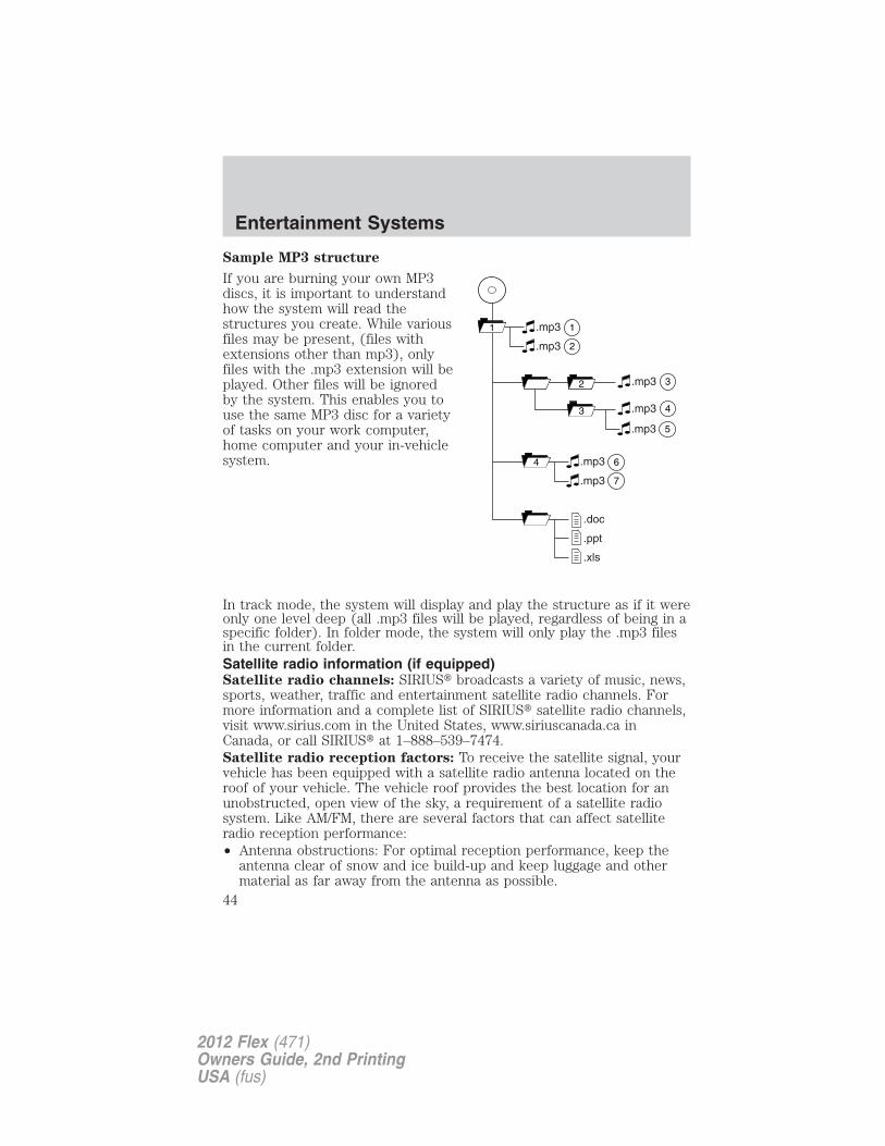
Sample MP3 structure
If you are burning your own MP3discs, it is important to understandhow the system will read thestructures you create. While variousfiles may be present, (files withextensions other than mp3), onlyfiles with the .mp3 extension will beplayed. Other files will be ignoredby the system. This enables you touse the same MP3 disc for a varietyof tasks on your work computer,home computer and your in-vehiclesystem.
In track mode, the system will display and play the structure as if it wereonly one level deep (all .mp3 files will be played, regardless of being in aspecific folder). In folder mode, the system will only play the .mp3 filesin the current folder.Satellite radio information (if equipped)Satellite radio channels: SIRIUS� broadcasts a variety of music, news,sports, weather, traffic and entertainment satellite radio channels. Formore information and a complete list of SIRIUS� satellite radio channels,visit www.sirius.com in the United States, www.siriuscanada.ca inCanada, or call SIRIUS� at 1–888–539–7474.Satellite radio reception factors: To receive the satellite signal, yourvehicle has been equipped with a satellite radio antenna located on theroof of your vehicle. The vehicle roof provides the best location for anunobstructed, open view of the sky, a requirement of a satellite radiosystem. Like AM/FM, there are several factors that can affect satelliteradio reception performance:• Antenna obstructions: For optimal reception performance, keep the
antenna clear of snow and ice build-up and keep luggage and othermaterial as far away from the antenna as possible.
11
2
.mp3
2.mp3
3.mp3
3 4.mp3
64 .mp3
7.mp3
.doc
.ppt
.xls
5.mp3
Entertainment Systems
44
2012 Flex (471)Owners Guide, 2nd PrintingUSA (fus)
• Terrain: Hills, mountains, tall buildings, bridges, tunnels, freewayoverpasses, parking garages, dense tree foliage and thunderstorms caninterfere with your reception.
• Station overload: When you pass a ground based broadcast repeatingtower, a stronger signal may overtake a weaker one and result in anaudio mute.
Unlike AM/FM audible static, you will hear an audio mute when there isa satellite radio signal interference. Your radio display may display NOSIGNAL to indicate the interference.
SIRIUS� satellite radio service: SIRIUS� Satellite Radio is asubscription based satellite radio service that broadcasts music, sports,news and entertainment programming. A service fee is required in orderto receive SIRIUS� service. Vehicles that are equipped with a factoryinstalled SIRIUS� Satellite Radio system include:
• Hardware and limited subscription term, which begins on the date ofsale or lease of the vehicle.
For information on extended subscription terms, the online media playerand other SIRIUS� features, please contact SIRIUS� at 1–888–539–7474.
Note: SIRIUS� reserves the unrestricted right to change, rearrange, addor delete programming including canceling, moving or adding particularchannels, and its prices, at any time, with or without notice to you. FordMotor Company shall not be responsible for any such programmingchanges.
Satellite Radio Electronic Serial Number (ESN): This 12-digitSatellite Serial Number is needed to activate, modify or track yoursatellite radio account. You will need this number when communicatingwith SIRIUS. While in Satellite Radio mode, you can view this number onthe radio display by pressing the SIRIUS and Preset 1 buttons at thesame time.
Entertainment Systems
45
2012 Flex (471)Owners Guide, 2nd PrintingUSA (fus)
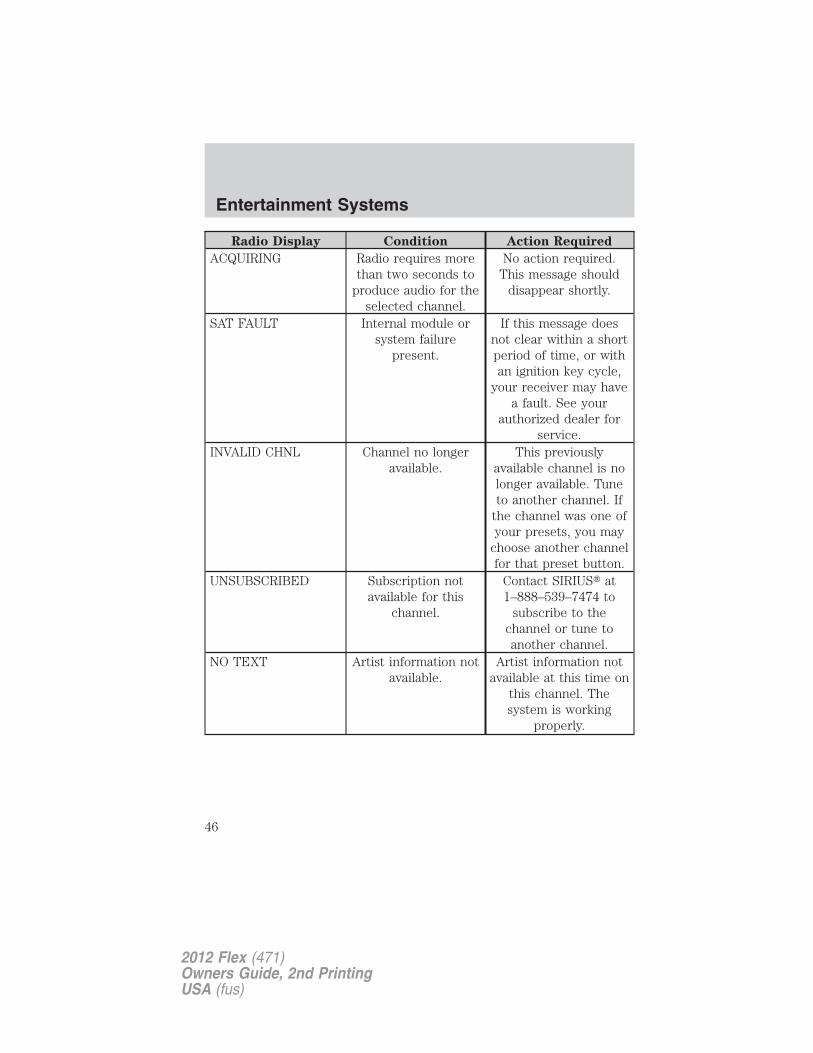
Radio Display Condition Action Required
ACQUIRING Radio requires morethan two seconds to
produce audio for theselected channel.
No action required.This message should
disappear shortly.
SAT FAULT Internal module orsystem failure
present.
If this message doesnot clear within a shortperiod of time, or withan ignition key cycle,
your receiver may havea fault. See your
authorized dealer forservice.
INVALID CHNL Channel no longeravailable.
This previouslyavailable channel is nolonger available. Tuneto another channel. If
the channel was one ofyour presets, you may
choose another channelfor that preset button.
UNSUBSCRIBED Subscription notavailable for this
channel.
Contact SIRIUS� at1–888–539–7474 to
subscribe to thechannel or tune toanother channel.
NO TEXT Artist information notavailable.
Artist information notavailable at this time on
this channel. Thesystem is working
properly.
Entertainment Systems
46
2012 Flex (471)Owners Guide, 2nd PrintingUSA (fus)
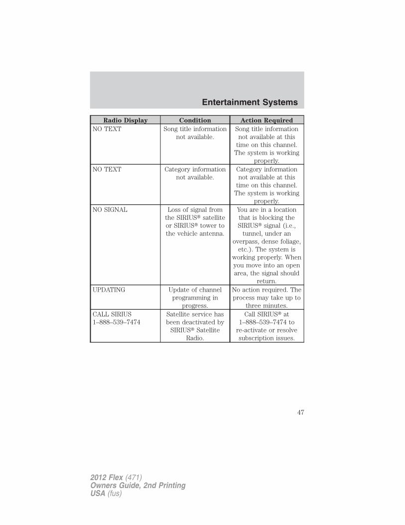
Radio Display Condition Action Required
NO TEXT Song title informationnot available.
Song title informationnot available at this
time on this channel.The system is working
properly.NO TEXT Category information
not available.Category informationnot available at this
time on this channel.The system is working
properly.NO SIGNAL Loss of signal from
the SIRIUS� satelliteor SIRIUS� tower tothe vehicle antenna.
You are in a locationthat is blocking theSIRIUS� signal (i.e.,
tunnel, under anoverpass, dense foliage,
etc.). The system isworking properly. Whenyou move into an openarea, the signal should
return.UPDATING Update of channel
programming inprogress.
No action required. Theprocess may take up to
three minutes.CALL SIRIUS1–888–539–7474
Satellite service hasbeen deactivated by
SIRIUS� SatelliteRadio.
Call SIRIUS� at1–888–539–7474 to
re-activate or resolvesubscription issues.
Entertainment Systems
47
2012 Flex (471)Owners Guide, 2nd PrintingUSA (fus)
FAMILY ENTERTAINMENT DVD SYSTEM (IF EQUIPPED)
WARNING: Driving while distracted can result in loss of vehiclecontrol, accident and injury. Ford strongly recommends that
drivers use extreme caution when using any device or feature that maytake their focus off the road. Your primary responsibility is the safeoperation of the vehicle. We recommend against the use of anyhandheld device while driving, encourage the use of voice-operatedsystems when possible and that you become aware of applicable stateand local laws that may affect use of electronic devices while driving.
Your vehicle may be equipped with a Family Entertainment System(FES) which allows you to listen to audio CDs, MP3 discs, watch DVDsand to plug in and play a variety of standard video game systems. Theheadrest-mounted DVD players are capable of playing standard DVDs,CDs, MP3s and are compatible with Video CD, HDCD, Hybrid SACD(play CD layer only), SVCD, DVD-video, JPEGs, up to MPEG-4 files, MP3files and WMA media. Please review this material to become familiar withthe FES features and controls as well as the very important safetyinformation.Quick startYour family entertainment system includes two headrest-mounted DVDplayer/screens, two sets of wireless infrared (IR) headphones and awireless infrared (IR) remote control capable of controlling either DVDplayer. Both DVD players are capable of playing their own independentmedia, or they can both watch the same media.When in single play mode, the headrest video sources that have beenselected at each headrest will play through the speakers, but no audio isavailable through the headphones.To play a DVD1. Insert a DVD into the system, label side facing the rear passengers.The disc slot indicator lights will illuminate. The system willautomatically load the disc and it will begin to play. LOADING willappear in the screen.2. If there is already a disc in the system, press the power button on theDVD system and then press (Play) to begin to play the disc.
3. Use the bezel controls to play ( ) pause ( ), stop ( ), or
eject ( ) a DVD.Press / to access the previous/next chapter. Press and hold for afast reverse/forward search.
Entertainment Systems
48
2012 Flex (471)Owners Guide, 2nd PrintingUSA (fus)
Note: The system goes into dual play mode when it is turned on. Audiofrom the DVD system will not play over the rear two speakers until dualplay mode is turned off. When dual play mode is turned on, the audiosound plays over the front two speakers until dual play mode is turnedoff.
Note: Each headrest monitor is labeled with an identifier (either A or B)found in the upper right corner of the system.
To watch a DVD playing in the other headrest system: Press MEDIArepeatedly until the desired system (Monitor A or Monitor B) appears inthe display.
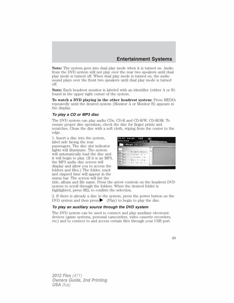
To play a CD or MP3 disc
The DVD system can play audio CDs, CD-R and CD-R/W, CD-ROM. Toensure proper disc operation, check the disc for finger prints andscratches. Clean the disc with a soft cloth, wiping from the center to theedge.
1. Insert a disc into the system,label side facing the rearpassengers. The disc slot indicatorlights will illuminate. The systemwill automatically load the disc andit will begin to play. (If it is an MP3,the MP3 audio disc screen willdisplay and allow you to access thefolders and files.) The folder, trackand elapsed time will appear in thestatus bar. The screen will list thetitle, album and file name. Press the arrow controls on the headrest DVDsystem to scroll through the folders. When the desired folder ishighlighted, press SEL to confirm the selection.
2. If there is already a disc in the system, press the power button on theDVD system and then press (Play) to begin to play the disc.
To play an auxiliary source through the DVD system
The DVD system can be used to connect and play auxiliary electronicdevices (game systems, personal camcorders, video cassette recorders,etc) and to connect to and access certain files through your USB port.
Entertainment Systems
49
2012 Flex (471)Owners Guide, 2nd PrintingUSA (fus)
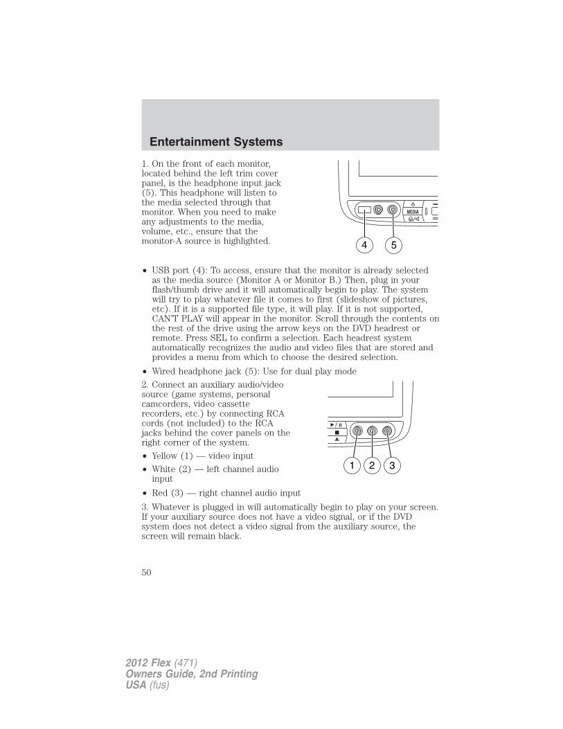
1. On the front of each monitor,located behind the left trim coverpanel, is the headphone input jack(5). This headphone will listen tothe media selected through thatmonitor. When you need to makeany adjustments to the media,volume, etc., ensure that themonitor-A source is highlighted.
• USB port (4): To access, ensure that the monitor is already selectedas the media source (Monitor A or Monitor B.) Then, plug in yourflash/thumb drive and it will automatically begin to play. The systemwill try to play whatever file it comes to first (slideshow of pictures,etc). If it is a supported file type, it will play. If it is not supported,CAN’T PLAY will appear in the monitor. Scroll through the contents onthe rest of the drive using the arrow keys on the DVD headrest orremote. Press SEL to confirm a selection. Each headrest systemautomatically recognizes the audio and video files that are stored andprovides a menu from which to choose the desired selection.
• Wired headphone jack (5): Use for dual play mode
2. Connect an auxiliary audio/videosource (game systems, personalcamcorders, video cassetterecorders, etc.) by connecting RCAcords (not included) to the RCAjacks behind the cover panels on theright corner of the system.
• Yellow (1) — video input
• White (2) — left channel audioinput
• Red (3) — right channel audio input
3. Whatever is plugged in will automatically begin to play on your screen.If your auxiliary source does not have a video signal, or if the DVDsystem does not detect a video signal from the auxiliary source, thescreen will remain black.
MEDIA
4 5
Entertainment Systems
50
2012 Flex (471)Owners Guide, 2nd PrintingUSA (fus)
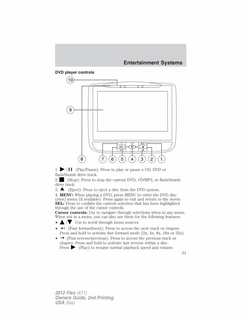
DVD player controls
1. / (Play/Pause): Press to play or pause a CD, DVD orflash/thumb drive track.2. (Stop): Press to stop the current DVD, CD/MP3, or flash/thumbdrive track.3. (Eject): Press to eject a disc from the DVD system.4. MENU: When playing a DVD, press MENU to enter the DVD disc(root) menu (if available). Press again to exit and return to the movie.SEL: Press to confirm the current selection that has been highlightedthrough the use of the cursor controls.Cursor controls: Use to navigate through selections when in any menu.When not in a menu, you can also use them for the following features:• / Use to scroll through menu sources.
• (Fast forward/next): Press to access the next track or chapter.Press and hold to activate fast forward mode (2x, 4x, 8x, 16x or 32x).
• (Fast reverse/previous): Press to access the previous track orchapter. Press and hold to activate fast reverse within a disc.Press (Play) to resume normal playback speed and volume.
MEDIA MENUSEL
47 56 13 28
9
10
Entertainment Systems
51
2012 Flex (471)Owners Guide, 2nd PrintingUSA (fus)
5. / (Headphones/Speakers): Press to activate dual play mode oneither headrest system. During dual play mode, the following happens:a. Rear speakers turn offb. Headphones become active on both headrest systems.c. Media sources become available through the DVD systems.Note: If the system is in dual play mode, you must press the /(Headphones/Speakers) button on both headrest systems in order toreturn to single play. For more information, please refer to Singleplay/Dual play later in this section.
6. MEDIA for Monitor A: In Dual Play mode, press MEDIA repeatedlyto select from the possible media sources: (Monitor A, Monitor B, AM,FM1, FM2, SR1, SR2, SR3 (satellite radio, if equipped), Disc, Jukebox (ifequipped) and SYNC� (if equipped). The selected media type willdisplay on the screen. When Monitor A is chosen, you can also use theauxiliary inputs and the USB port on the headrest system.MEDIA for Monitor B: In Dual Play mode, press MEDIA repeatedly toselect from the possible media sources: (Monitor A, Monitor B). Theselected media type will display on the screen. When Monitor B ischosen, you can also use the auxiliary inputs and USB port on theheadrest system.For further information, please refer to Single play/Dual play later inthis section.Note: Each headrest monitor is labeled with an identifier (either A or B)found in the upper right corner of the system.
7. (On/Off): Press to turn the system on/off. Power for headrest A isseparate from headrest B.Note: This also disables dual play. When both headrest systems areturned off, the system will return to single play mode.
8. Infrared receiver (IR): System sensor which reads the signals fromthe remote control and also sends audio signals to the infrared wirelessheadphones.
9. LCD screen: This seven inch liquid crystal display (LCD) screen canbe adjusted for easier viewing by children. Pull the top of the screenpanel toward the viewer at the IR receiver/transmitter cover for a betterviewing angle. The screen is hinged at the bottom and pivots to facedownward. Push the screen back in place until it latches to return it to astowed position.Note: Ensure that you do not pull the LCD screen too far forward as itcan cause damage.
10. CD/DVD slot: Insert the disc, label side facing the rear passengers.
Entertainment Systems
52
2012 Flex (471)Owners Guide, 2nd PrintingUSA (fus)
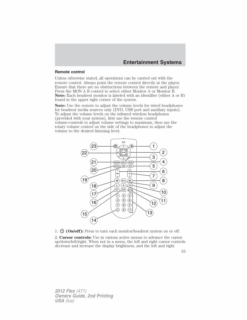
Remote control
Unless otherwise stated, all operations can be carried out with theremote control. Always point the remote control directly at the player.Ensure that there are no obstructions between the remote and player.Press the MON A B control to select either Monitor A or Monitor B.Note: Each headrest monitor is labeled with an identifier (either A or B)found in the upper right corner of the system.
Note: Use the remote to adjust the volume levels for wired headphonesfor headrest media sources only (DVD, USB port and auxiliary inputs).To adjust the volume levels on the infrared wireless headphones(provided with your system), first use the remote controlvolume-controls to adjust volume settings to maximum, then use therotary volume control on the side of the headphones to adjust thevolume to the desired listening level.
1. (On/off): Press to turn each monitor/headrest system on or off.
2. Cursor controls: Use in various active menus to advance the cursorup/down/left/right. When not in a menu, the left and right cursor controlsdecrease and increase the display brightness, and the left and right
Entertainment Systems
53
2012 Flex (471)Owners Guide, 2nd PrintingUSA (fus)
cursor controls advance to the next or previous station when accessingthe radio tuner in dual play mode (AM/FM/SR).
3. DISPLAY: Press to access the on-screen display of title track, chapterand time elapsed.
4. RETURN: Press to return to the previous menu screen.
5. SETUP: Press to access the setup menu for each monitor. Refer toSetup Menu later in this section for more information.
6. MON A/B: Press to select either monitor A or monitor B to becontrolled by the remote control.
7. VOL (Volume): When in Dual Play only, press to increase ( ) ordecrease ( ) the volume for the wired headphones for headrest mediasources only (DVD, USB port and auxiliary inputs). (Wireless headphonevolume is controlled with the rotary dial on the right ear piece.)
8. Fast Forward/Next: In DVD mode, press and hold for a quickadvance within the DVD. Press and release to advance to the nextchapter. In CD/MP3 mode, press to access the next track. When using aflash/thumb drive, press to access the next track.
9. Play/Pause: Press to play or pause a DVD, disc or flash/thumb drivetrack.
10. TITLE: Press to access the on-screen display of the root DVD discmenu.
11. STOP: Press to stop the current DVD, disc or flash/thumb drivetrack.
12. / Speaker/Headphone (Single/Dual Play): Press to switchbetween Single Play (same media playing through all speakers) and DualPlay (headphone mode, the rear speakers are muted). You can also pressthe 2 and 4 memory presets on the audio system at the same time toperform the same function.Note: Whenever either headrest system presses this button, bothsystems will automatically go into dual play mode. In order to return tosingle play mode, you must press this button on both headrest systems.
13. Numeric Keypad: Use the numeric controls to enter in a specificCD/MP3 track or DVD chapter to be played.
14. C (Cancel): Press to cancel/clear the numeric input (i.e. chapternumber).
Entertainment Systems
54
2012 Flex (471)Owners Guide, 2nd PrintingUSA (fus)
15. MEDIA for Monitor A: In Dual Play mode, press MEDIA repeatedlyto select from the possible media sources: (Monitor A, Monitor B, AM,FM1, FM2, SR1, SR2, SR3 (satellite radio, if equipped), Disc, Jukebox (ifequipped) and SYNC� (if equipped). The selected media type willdisplay on the screen. When Monitor A is chosen, you can also use theauxiliary inputs and the USB port on the headrest system.MEDIA for Monitor B: In Dual Play mode, press MEDIA repeatedly toselect from the possible media sources: (Monitor A, Monitor B). Theselected media type will display on the screen. When Monitor B ischosen, you can also use the auxiliary inputs and USB port on theheadrest system.For further information, please refer to Single play/Dual play later inthis section.Note: Each headrest monitor is labeled with an identifier (either A or B)found in the upper right corner of the system.
16. MUTE: Press to mute the volume of the active media source.(headphone and speakers, where applicable.) Press again to restorevolume.
17. EJECT: Press to eject a disc from the system. OPEN will display onthe screen.
18. Fast reverse/Previous: When a DVD is playing, press and hold for aquick reverse within the DVD. Press and release for the previouschapter. Press PLAY to resume normal playback speed and volume.In CD/MP3 mode, press to access the previous track. When using aflash/thumb drive, press to access the next track.
19. MENU: Press to access the DVD or CD disc menu for selections.Press again to return to DVD play.Note: For certain discs, you may need to press ENTER to return to DVDplay.
20. SUBTITLE (DVD dependent): Press to turn the subtitle feature ONor OFF.
21. LANGUAGE (DVD dependent): Press to select the desiredlanguage.
22. ENTER: Press to select the highlighted menu option.
23. ILLUMINATION: Press to illuminate the remote control andbacklight all of the buttons for night use.
Entertainment Systems
55
2012 Flex (471)Owners Guide, 2nd PrintingUSA (fus)
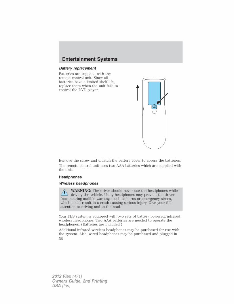
Battery replacementBatteries are supplied with theremote control unit. Since allbatteries have a limited shelf life,replace them when the unit fails tocontrol the DVD player.
Remove the screw and unlatch the battery cover to access the batteries.The remote control unit uses two AAA batteries which are supplied withthe unit.
Headphones
Wireless headphones
WARNING: The driver should never use the headphones whiledriving the vehicle. Using headphones may prevent the driver
from hearing audible warnings such as horns or emergency sirens,which could result in a crash causing serious injury. Give your fullattention to driving and to the road.
Your FES system is equipped with two sets of battery powered, infraredwireless headphones. Two AAA batteries are needed to operate theheadphones. (Batteries are included.)
Additional infrared wireless headphones may be purchased for use withthe system. Also, wired headphones may be purchased and plugged in
Entertainment Systems
56
2012 Flex (471)Owners Guide, 2nd PrintingUSA (fus)
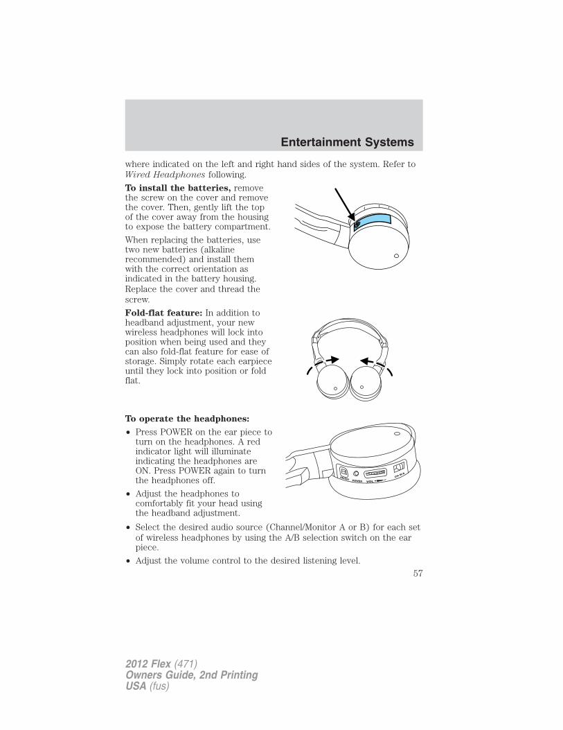
where indicated on the left and right hand sides of the system. Refer toWired Headphones following.
To install the batteries, removethe screw on the cover and removethe cover. Then, gently lift the topof the cover away from the housingto expose the battery compartment.
When replacing the batteries, usetwo new batteries (alkalinerecommended) and install themwith the correct orientation asindicated in the battery housing.Replace the cover and thread thescrew.
Fold-flat feature: In addition toheadband adjustment, your newwireless headphones will lock intoposition when being used and theycan also fold-flat feature for ease ofstorage. Simply rotate each earpieceuntil they lock into position or foldflat.
To operate the headphones:
• Press POWER on the ear piece toturn on the headphones. A redindicator light will illuminateindicating the headphones areON. Press POWER again to turnthe headphones off.
• Adjust the headphones tocomfortably fit your head usingthe headband adjustment.
• Select the desired audio source (Channel/Monitor A or B) for each setof wireless headphones by using the A/B selection switch on the earpiece.
• Adjust the volume control to the desired listening level.
Entertainment Systems
57
2012 Flex (471)Owners Guide, 2nd PrintingUSA (fus)
Ensure that the headphones are turned off when not in use. Afterapproximately one minute of not being in use (no infrared signal isreceived), the wireless headphones will automatically turn off. They willalso turn off after two hours of continuous use as a power save feature.If this happens, simply turn the headphones on again and continue use.
Wired headphones
WARNING: Do not leave children unattended in the vehicle anddo not let children operate the system while unsupervised. If
wired headphones or auxiliary systems are used, children may becomeentangled in the cords and seriously injure themselves.
WARNING: The driver should never use the headphones whiledriving the vehicle. Using headphones may prevent the driver
from hearing audible warnings such as horns or emergency sirens,which could result in a crash causing serious injury. Give your fullattention to driving and to the road.
Wired headphone jacks on the FES (Family Entertainment System) areuniversal so you may purchase and use additional wired headphones foryour system. Plug them into the 3.5 mm headphone jack(s) locatedbehind the trim covers on the face of each monitor. These headphoneswill be active when in Dual Play mode.
To listen to the audio on wired headphones (not included), connect thewired headphones into the monitor headphone jacks. Available wiredheadphone sources are limited to the sources available to whichevermonitor is being listened to. Adjust the volume using the volume controlon the DVD system remote control.
Operation
Single play/dual playYour DVD and audio system work together with the infrared headphonesand wired headphones (not included) to allow the rear seat passengersto listen to the radio (and other media sources) over the headphones.This enables the front and rear seat passengers to listen to a variety ofsources a variety of ways.
Single Play: Single play consists of all occupants in the vehicle listeningto the same playing media over the front and rear speakers. When theDVD system is on and in single play, the same source will play throughall vehicle speakers.
Entertainment Systems
58
2012 Flex (471)Owners Guide, 2nd PrintingUSA (fus)
Dual Play: Dual play is when the rear seat passengers choose to listento a different playing media than the front seat passengers. With theDVD and rear seat controls turned on, the rear seat passengers maychoose to listen to: Monitor A, Monitor B, AM, FM1, FM2 SR1, SR2, SR3(satellite radio, if equipped), Disc, Jukebox (if equipped), or SYNC� (ifequipped). While the front speakers play the chosen selection for thefront audio system, the rear seat passengers can listen to another overthe headphones. The headphone icon will appear in the displayindicating that the headphones are active.
You can access dual play mode in any of the following ways:
• If your vehicle is equipped with a touchscreen system:a. Ensure that the vehicle ignition is turned on. Inserting a DVD intothe system will automatically activate dual play mode.b. Press the RADIO or MEDIA hard button. Select the ‘Rear Zone’ tabon the touchscreen and select ‘On’ for the headphones and ‘Enabled’for the rear controls. To return to single zone, select ‘Off’ for theheadphones.
• If your vehicle is equipped with a non-touchscreen system:a. Press the headphone/speaker ( / ) button on the remotecontrol or DVD system. Press again on both headrest systems toreturn to single play mode.b. Press the 2 and 4 memory presets on the radio at the same time.Press again to return to single play mode.
Note: If the front seat passengers are listening to the radio, the rear seatpassengers can also listen to the radio; however, they will be limited tolistening to the same radio channel.
• Once you have entered Dual play mode, the Channel A or Channel Bcontrols on the headphones are now active. Both Channel A andChannel B can be listened to on the wired headphones (not included)or on the infrared (IR) wireless headphones.
• On the wireless headphones, select the Channel A or Channel Bbuttons on each pair of wireless headphones.
• Press MEDIA to change the audio source for the Channel A orChannel B headphones. (This information will display on the DVDsystem screen).Note: Channel B headphones can only listen to either the DVD media,Monitor A or the DVD system auxiliary inputs. Channel A headphoneshave access to all available media sources.
Entertainment Systems
59
2012 Flex (471)Owners Guide, 2nd PrintingUSA (fus)
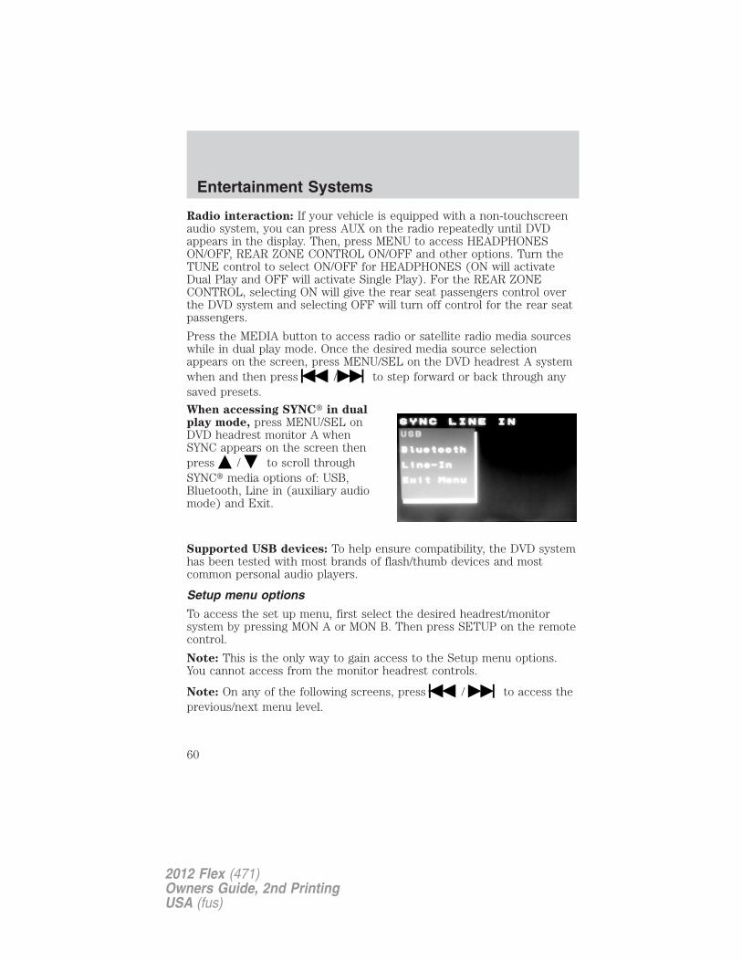
Radio interaction: If your vehicle is equipped with a non-touchscreenaudio system, you can press AUX on the radio repeatedly until DVDappears in the display. Then, press MENU to access HEADPHONESON/OFF, REAR ZONE CONTROL ON/OFF and other options. Turn theTUNE control to select ON/OFF for HEADPHONES (ON will activateDual Play and OFF will activate Single Play). For the REAR ZONECONTROL, selecting ON will give the rear seat passengers control overthe DVD system and selecting OFF will turn off control for the rear seatpassengers.
Press the MEDIA button to access radio or satellite radio media sourceswhile in dual play mode. Once the desired media source selectionappears on the screen, press MENU/SEL on the DVD headrest A systemwhen and then press / to step forward or back through anysaved presets.
When accessing SYNC� in dualplay mode, press MENU/SEL onDVD headrest monitor A whenSYNC appears on the screen thenpress / to scroll throughSYNC� media options of: USB,Bluetooth, Line in (auxiliary audiomode) and Exit.
Supported USB devices: To help ensure compatibility, the DVD systemhas been tested with most brands of flash/thumb devices and mostcommon personal audio players.
Setup menu options
To access the set up menu, first select the desired headrest/monitorsystem by pressing MON A or MON B. Then press SETUP on the remotecontrol.
Note: This is the only way to gain access to the Setup menu options.You cannot access from the monitor headrest controls.
Note: On any of the following screens, press / to access theprevious/next menu level.
Entertainment Systems
60
2012 Flex (471)Owners Guide, 2nd PrintingUSA (fus)
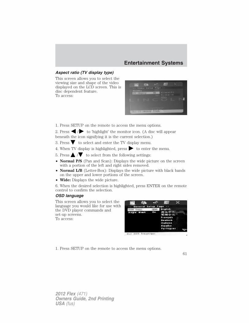
Aspect ratio (TV display type)This screen allows you to select theviewing size and shape of the videodisplayed on the LCD screen. This isdisc dependent feature.To access:
1. Press SETUP on the remote to access the menu options.
2. Press / to ’highlight’ the monitor icon. (A disc will appearbeneath the icon signifying it is the current selection.)
3. Press to select and enter the TV display menu.
4. When TV display is highlighted, press to enter the menu.
5. Press / to select from the following settings:
• Normal P/S (Pan and Scan): Displays the wide picture on the screenwith a portion of the left and right sides removed.
• Normal L/B (Letter-Box): Displays the wide picture with black bandson the upper and lower portions of the screen.
• Wide: Displays the wide picture.
6. When the desired selection is highlighted, press ENTER on the remotecontrol to confirm the selection.OSD languageThis screen allows you to select thelanguage you would like for use withthe DVD player commands andset-up screens.To access:
1. Press SETUP on the remote to access the menu options.
Entertainment Systems
61
2012 Flex (471)Owners Guide, 2nd PrintingUSA (fus)
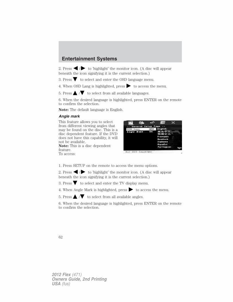
2. Press / to ’highlight’ the monitor icon. (A disc will appearbeneath the icon signifying it is the current selection.)
3. Press to select and enter the OSD language menu.
4. When OSD Lang is highlighted, press to access the menu.
5. Press / to select from all available languages.
6. When the desired language is highlighted, press ENTER on the remoteto confirm the selection.
Note: The default language is English.
Angle markThis feature allows you to selectfrom different viewing angles thatmay be found on the disc. This is adisc dependent feature. If the DVDdoes not have this capability, it willnot be available.Note: This is a disc dependentfeature.To access:
1. Press SETUP on the remote to access the menu options.
2. Press / to ’highlight’ the monitor icon. (A disc will appearbeneath the icon signifying it is the current selection.)
3. Press to select and enter the TV display menu.
4. When Angle Mark is highlighted, press to access the menu.
5. Press / to select from all available angles.
6. When the desired language is highlighted, press ENTER on the remoteto confirm the selection.
Entertainment Systems
62
2012 Flex (471)Owners Guide, 2nd PrintingUSA (fus)
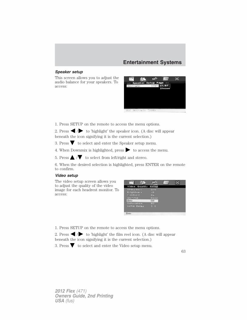
Speaker setupThis screen allows you to adjust theaudio balance for your speakers. Toaccess:
1. Press SETUP on the remote to access the menu options.
2. Press / to ’highlight’ the speaker icon. (A disc will appearbeneath the icon signifying it is the current selection.)
3. Press to select and enter the Speaker setup menu.
4. When Downmix is highlighted, press to access the menu.
5. Press / to select from left/right and stereo.
6. When the desired selection is highlighted, press ENTER on the remoteto confirm.
Video setupThe video setup screen allows youto adjust the quality of the videoimage for each headrest monitor. Toaccess:
1. Press SETUP on the remote to access the menu options.
2. Press / to ’highlight’ the film reel icon. (A disc will appearbeneath the icon signifying it is the current selection.)
3. Press to select and enter the Video setup menu.
Entertainment Systems
63
2012 Flex (471)Owners Guide, 2nd PrintingUSA (fus)
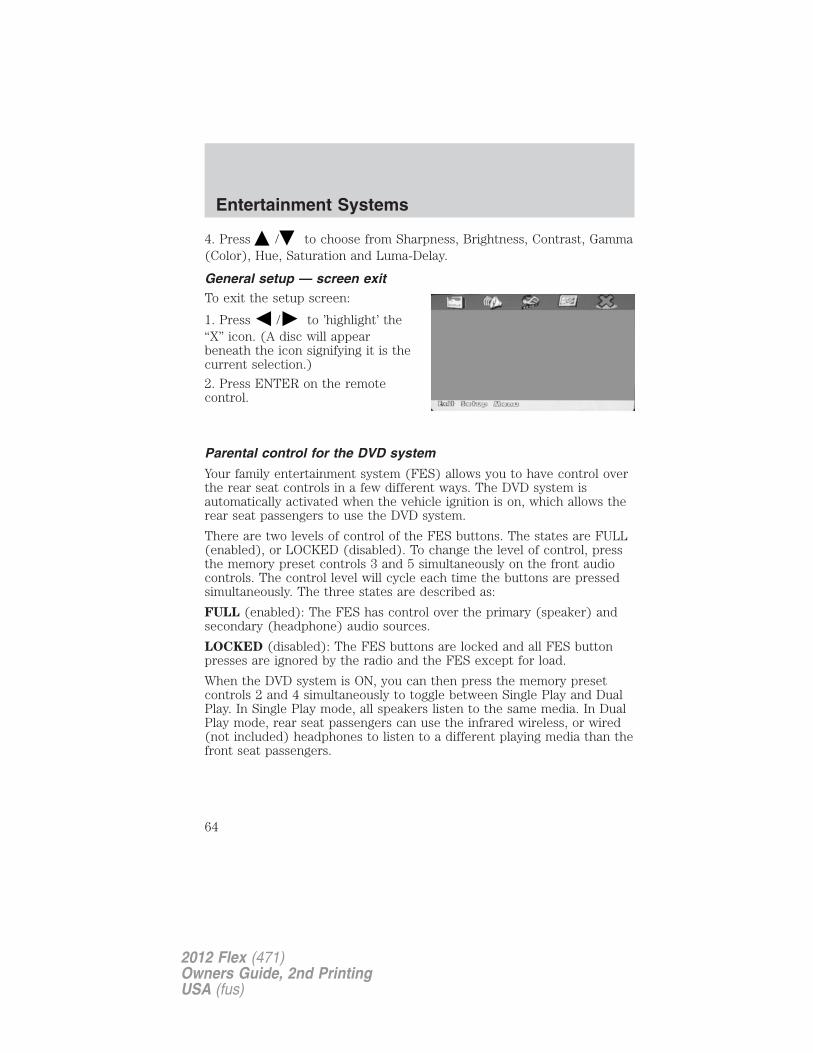
4. Press / to choose from Sharpness, Brightness, Contrast, Gamma(Color), Hue, Saturation and Luma-Delay.
General setup — screen exitTo exit the setup screen:
1. Press / to ’highlight’ the“X” icon. (A disc will appearbeneath the icon signifying it is thecurrent selection.)
2. Press ENTER on the remotecontrol.
Parental control for the DVD system
Your family entertainment system (FES) allows you to have control overthe rear seat controls in a few different ways. The DVD system isautomatically activated when the vehicle ignition is on, which allows therear seat passengers to use the DVD system.
There are two levels of control of the FES buttons. The states are FULL(enabled), or LOCKED (disabled). To change the level of control, pressthe memory preset controls 3 and 5 simultaneously on the front audiocontrols. The control level will cycle each time the buttons are pressedsimultaneously. The three states are described as:
FULL (enabled): The FES has control over the primary (speaker) andsecondary (headphone) audio sources.
LOCKED (disabled): The FES buttons are locked and all FES buttonpresses are ignored by the radio and the FES except for load.
When the DVD system is ON, you can then press the memory presetcontrols 2 and 4 simultaneously to toggle between Single Play and DualPlay. In Single Play mode, all speakers listen to the same media. In DualPlay mode, rear seat passengers can use the infrared wireless, or wired(not included) headphones to listen to a different playing media than thefront seat passengers.
Entertainment Systems
64
2012 Flex (471)Owners Guide, 2nd PrintingUSA (fus)
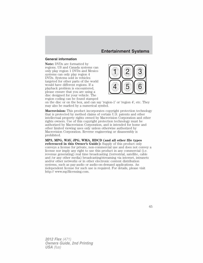
General informationNote: DVDs are formatted byregions. US and Canada systems canonly play region 1 DVDs and Mexicosystems can only play region 4DVDs. Systems sold in vehiclestargeted for other parts of the worldwould have different regions. If aplayback problem is encountered,please ensure that you are using adisc designed for your vehicle. Theregion coding can be found stampedon the disc or on the box, and can say ‘region-1’ or ‘region 4’, etc. Theymay also be marked by a numerical symbol.
Macrovision: This product incorporates copyright protection technologythat is protected by method claims of certain U.S. patents and otherintellectual property rights owned by Macrovision Corporation and otherrights owners. Use of this copyright protection technology must beauthorized by Macrovision Corporation, and is intended for home andother limited viewing uses only unless otherwise authorized byMacrovision Corporation. Reverse engineering or disassembly isprohibited.
MP3, MPG, WAV, JPG, WMA, HDCD (and all other file typesreferenced in this Owner’s Guide): Supply of this product onlyconveys a license for private, non-commercial use and does not convey alicense nor imply any right to use this product in any commercial (i.e.revenue generating) real time broadcasting (terrestrial, satellite, cableand /or any other media) broadcasting/streaming via internet, intranetsand/or other networks or in other electronic content distributionsystems, such as pay-audio or audio-on-demand applications. Anindependent license for such use is required. For details, please visithttp:// www.mp3licensing.com.
Entertainment Systems
65
2012 Flex (471)Owners Guide, 2nd PrintingUSA (fus)
Safety information
WARNING: Driving while distracted can result in loss of vehiclecontrol, accident and injury. Ford strongly recommends that
drivers use extreme caution when using any device or feature that maytake their focus off the road. Your primary responsibility is the safeoperation of the vehicle. We recommend against the use of anyhandheld device while driving, encourage the use of voice-operatedsystems when possible and that you become aware of applicable stateand local laws that may affect the use of electronic devices whiledriving.
Read all of the safety and operating instructions before operating thesystem and retain for future reference.Do not attempt to service, repair or modify the Family EntertainmentSystem (FES). See your dealer.Do not insert foreign objects into the DVD compartment.
WARNING: Do not leave children unattended in the vehicle anddo not let children operate the system while unsupervised. If
wired headphones or auxiliary systems are used, children may becomeentangled in the cords and seriously injure themselves.
WARNING: The front glass on the liquid crystal display (LCD)flip-down screen may break when hit with a hard surface. If the
glass breaks, do not touch the liquid crystalline material. In case ofcontact with skin, wash immediately with soap and water.
WARNING: The driver should not attempt to operate anyfunction of the DVD system while the vehicle is in motion. Give
full attention to driving and to the road. Pull off the road in a safeplace before inserting or extracting DVDs from the system. A remotecontrol is included in the system to allow the rear seat occupants tooperate the FES functions without distracting the driver.
Do not expose the liquid crystal display (LCD) flip-down screento direct sunlight or intensive ultraviolet rays for extensiveperiods of time. Ultraviolet rays deteriorate the liquid crystal.
Be sure to review User Manuals for video games and video gameequipment when used as auxiliary inputs for your Family EntertainmentSystem (FES).
Entertainment Systems
66
2012 Flex (471)Owners Guide, 2nd PrintingUSA (fus)
Do not operate video games or video equipment if the power cordsand/or cables are broken, split or damaged. Carefully place cords and/orcables where they will not be stepped on or interfere with the operationof seats and/or compartments.Disconnect video games and video equipment power cords and/or cableswhen not in use.Avoid touching auxiliary input jacks with your fingers. Do not blow onthem or allow them to get wet or dirty.Do not clean any part of the DVD player with benzene, lacquer thinner,acetone, or any other solvent.
Federal Communication Commission (FCC) ComplianceChanges or modifications not approved by Ford Lincoln-Mercury couldvoid user’s authority to operate the equipment. This equipment has beentested and found to comply with the limits for a Class B digital device,pursuant to Part 15 of the FCC Rules. These limits are designed toprovide reasonable protection against harmful interference in aresidential installation. This equipment generates, uses and can radiateradio frequency energy and, if not installed and used in accordance withthe instructions, may cause harmful interference and radiocommunications.However, there is no guarantee that interference will not occur in aparticular installation. If this equipment does cause harmful interferenceto radio or television reception, which can be determined by turning theequipment off and on, the user is encouraged to consult the dealer or anexperienced radio/TV technician for help.Care and service of the DVD player
Environmental extremesDVD players which are subjected to harsh environmental conditions maybe damaged or perform at less than maximum capability. To avoid theseoutcomes, whenever possible avoid exposing your DVD player to:• extremely hot or cold temperatures.• direct sunlight.• high humidity.• a dusty environment.• locations where strong magnetic fields are generated.
Temperature extremesWhen the vehicle is parked under direct sunlight or in an extremely coldplace for a long period of time, wait until the cabin temperature of thevehicle is at normal temperature before operating the system.
Entertainment Systems
67
2012 Flex (471)Owners Guide, 2nd PrintingUSA (fus)
Humidity and moisture condensationMoisture in the air will condense in the DVD player under extremelyhumid conditions or when moving from a cold place to a warm one.Moisture condensation may cause damage to the DVD and/or player. Ifmoisture condensation occurs, do not insert a CD or DVD into theplayer. If one is already in the player, remove it. Turn the DVD player ONto dry the moisture before inserting a DVD. This could take an hour ormore.
Foreign substancesExercise care to prevent dirt and foreign objects from entering the DVDplayer compartment. Be especially careful not to spill liquids of any kindonto the media controls or into the system. If liquid is accidentallyspilled onto the system, immediately turn the system OFF and consult aqualified service technician.
Cleaning the liquid crystal display (LCD) screenClean the display screen by applying a small amount of water or anyammonia-based household glass cleaner directly to a soft cloth. Rub thescreen gently until the dust, dirt or fingerprints are removed. Do notspray the screen directly with water or glass cleaning solvents. Oversprayfrom these fluids could drip down into the internal electronics of thescreen and cause damage. Do not apply excessive pressure whilecleaning the screen.
Cleaning DVD and CD discsInspect all discs for contamination before playing. If necessary, cleandiscs only with an approved DVD and CD cleaner and wipe from thecenter out to the edge. Do not use circular motion.
NAVIGATION SYSTEM (IF EQUIPPED)Your vehicle may be equipped with a navigation system. Refer to theNavigation System supplement for further information.
SYNC� (IF EQUIPPED)Your vehicle may be equipped with SYNC�, a hands-free communicationsand entertainment system with special phone and media features. Formore information, please refer to the SYNC� supplement or to theSYNC� section in the Navigation System supplement (if equipped).
Entertainment Systems
68
2012 Flex (471)Owners Guide, 2nd PrintingUSA (fus)
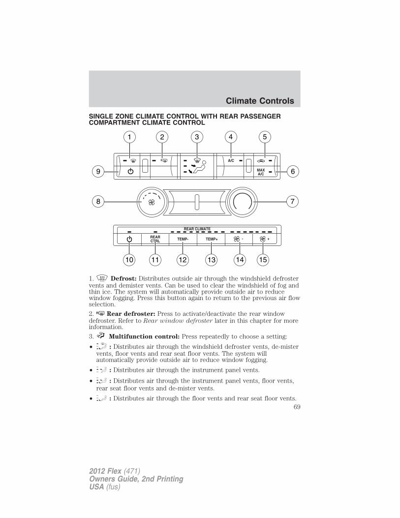
SINGLE ZONE CLIMATE CONTROL WITH REAR PASSENGERCOMPARTMENT CLIMATE CONTROL
1. Defrost: Distributes outside air through the windshield defrostervents and demister vents. Can be used to clear the windshield of fog andthin ice. The system will automatically provide outside air to reducewindow fogging. Press this button again to return to the previous air flowselection.
2. R Rear defroster: Press to activate/deactivate the rear windowdefroster. Refer to Rear window defroster later in this chapter for moreinformation.
3. Multifunction control: Press repeatedly to choose a setting:
• : Distributes air through the windshield defroster vents, de-mistervents, floor vents and rear seat floor vents. The system willautomatically provide outside air to reduce window fogging.
• : Distributes air through the instrument panel vents.
• : Distributes air through the instrument panel vents, floor vents,rear seat floor vents and de-mister vents.
• : Distributes air through the floor vents and rear seat floor vents.
Climate Controls
69
2012 Flex (471)Owners Guide, 2nd PrintingUSA (fus)
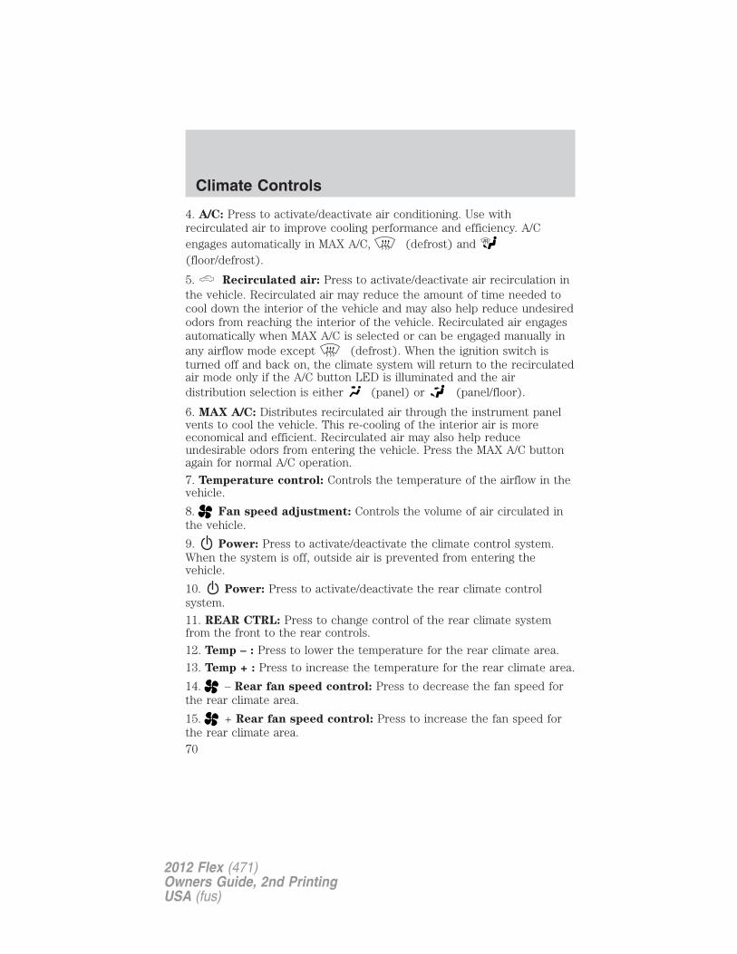
4. A/C: Press to activate/deactivate air conditioning. Use withrecirculated air to improve cooling performance and efficiency. A/Cengages automatically in MAX A/C, (defrost) and(floor/defrost).
5. Recirculated air: Press to activate/deactivate air recirculation inthe vehicle. Recirculated air may reduce the amount of time needed tocool down the interior of the vehicle and may also help reduce undesiredodors from reaching the interior of the vehicle. Recirculated air engagesautomatically when MAX A/C is selected or can be engaged manually inany airflow mode except (defrost). When the ignition switch isturned off and back on, the climate system will return to the recirculatedair mode only if the A/C button LED is illuminated and the airdistribution selection is either (panel) or (panel/floor).
6. MAX A/C: Distributes recirculated air through the instrument panelvents to cool the vehicle. This re-cooling of the interior air is moreeconomical and efficient. Recirculated air may also help reduceundesirable odors from entering the vehicle. Press the MAX A/C buttonagain for normal A/C operation.
7. Temperature control: Controls the temperature of the airflow in thevehicle.
8. Fan speed adjustment: Controls the volume of air circulated inthe vehicle.
9. Power: Press to activate/deactivate the climate control system.When the system is off, outside air is prevented from entering thevehicle.
10. Power: Press to activate/deactivate the rear climate controlsystem.
11. REAR CTRL: Press to change control of the rear climate systemfrom the front to the rear controls.
12. Temp – : Press to lower the temperature for the rear climate area.
13. Temp + : Press to increase the temperature for the rear climate area.
14. – Rear fan speed control: Press to decrease the fan speed forthe rear climate area.
15. + Rear fan speed control: Press to increase the fan speed forthe rear climate area.
Climate Controls
70
2012 Flex (471)Owners Guide, 2nd PrintingUSA (fus)
Operating tips
• To reduce fog build-up on the windshield during humid weather, placethe air flow selector in the position.
• To reduce humidity build-up inside the vehicle: do not drive with thesystem off or with recirculated air engaged.
• Do not put objects under the front seats that will interfere with theairflow to the back seats.
• Remove any snow, ice or leaves from the air intake area at the base ofthe windshield.
• A small amount of air may be felt from the floor vent regardless of theair distribution setting that is selected.
During extreme high ambient temperatures when idling stationary forextended periods of time in gear, it is recommended to run the A/C inthe MAX A/C position, turn off the rear A/C unit (if equipped), reduceblower fan speed from the highest setting and put the vehicle’stransmission into the P (Park) gear position to continue to receive coolair from your A/C system.
For maximum cooling performance in the MAX A/C mode:
• Press MAX A/C.
• Adjust the temperature to the coldest setting.
• Set the fan to the highest speed initially, then adjust to maintainpassenger comfort.
For maximum cooling performance in the and modes:
• Adjust the temperature to the coldest setting.
• Press A/C and recirculated air to provide colder airflow.
• Set the fan to the highest speed initially, then adjust to maintainpassenger comfort.
To aid in side window defogging/demisting in cold weather:
1. Select .
2. Press A/C.
3. Adjust the temperature to the warmest setting.
4. Set the fan speed to the highest setting.
5. Direct the outer instrument panel vents toward the side windows.
Climate Controls
71
2012 Flex (471)Owners Guide, 2nd PrintingUSA (fus)
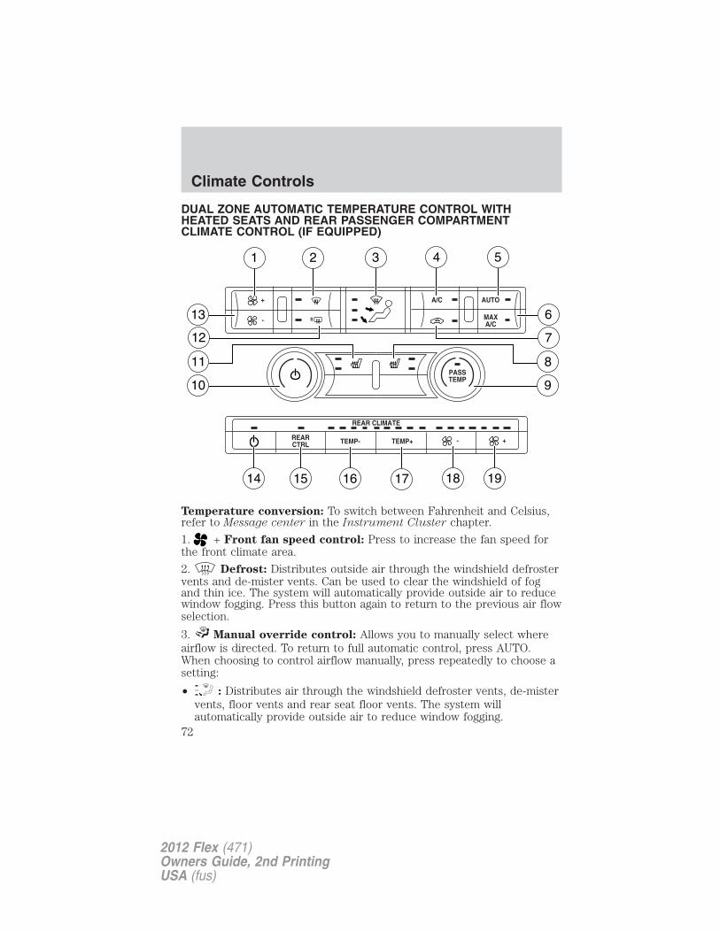
DUAL ZONE AUTOMATIC TEMPERATURE CONTROL WITHHEATED SEATS AND REAR PASSENGER COMPARTMENTCLIMATE CONTROL (IF EQUIPPED)
Temperature conversion: To switch between Fahrenheit and Celsius,refer to Message center in the Instrument Cluster chapter.
1. + Front fan speed control: Press to increase the fan speed forthe front climate area.
2. Defrost: Distributes outside air through the windshield defrostervents and de-mister vents. Can be used to clear the windshield of fogand thin ice. The system will automatically provide outside air to reducewindow fogging. Press this button again to return to the previous air flowselection.
3. Manual override control: Allows you to manually select whereairflow is directed. To return to full automatic control, press AUTO.When choosing to control airflow manually, press repeatedly to choose asetting:
• : Distributes air through the windshield defroster vents, de-mistervents, floor vents and rear seat floor vents. The system willautomatically provide outside air to reduce window fogging.
Climate Controls
72
2012 Flex (471)Owners Guide, 2nd PrintingUSA (fus)
• : Distributes air through the instrument panel vents.
• : Distributes air through the instrument panel vents, floor ventsand rear seat floor vents.
• : Distributes air through the floor vents and rear seat floor vents.
4. A/C: Press to activate/deactivate air conditioning. Use withrecirculated air to improve cooling performance and efficiency. A/Cengages automatically in MAX A/C, (defrost)and (floor/defrost).
5. AUTO: Press to engage automatic temperature control. Select thedesired temperature using the temperature control. The system willautomatically determine fan speed, airflow location, A/C on or off, andoutside or recirculated air, to heat or cool the vehicle to reach thedesired temperature.
6. MAX A/C: Distributes recirculated air through the instrument panelvents to cool the vehicle. This re-cooling of the interior air is moreeconomical and efficient. Recirculated air may also help reduceundesirable odors from entering the vehicle. Press the MAX A/C buttonagain for normal A/C operation.
7. Recirculated air: Press to activate/deactivate air recirculation inthe vehicle. Recirculated air may reduce the amount of time needed tocool down the interior of the vehicle and may also help reduce undesiredodors from reaching the interior of the vehicle. Recirculated air engagesautomatically when MAX A/C is selected or can be engaged manually inany airflow mode except (defrost). When the ignition switch isturned off and back on, the climate system will return to the recirculatedair mode only if the A/C button LED is illuminated and the airdistribution selection is either (panel) or (panel/floor).
Recirculation may turn off automatically in all airflow modes, exceptMAX A/C.
8. Passenger heated seat control: Press once to activate high heatsetting (two indicator lights), press again to activate low heat setting(one indicator light), and press again to deactivate the passenger heatedseat. Refer to Front seating in the Seating and Safety Restraintschapter for more information.
9. PASS TEMP: Press to activate separate passenger temperaturecontrol and turn the dial to increase/decrease the airflow temperature forthe passenger side of the vehicle.
Climate Controls
73
2012 Flex (471)Owners Guide, 2nd PrintingUSA (fus)
10. Power/cabin temperature: Press to activate/deactivate theclimate control system. When the system is off, outside air is preventedfrom entering the vehicle.
Turn the dial to increase/decrease the airflow temperature on thedriver side of the vehicle. This control also adjusts the passenger sidetemperature when PASS TEMP is off.
11. Driver heated seat control: Press to heat the driver seat. Pressonce to activate high heat (two indicator lights). Press again to activatelow heat (one indicator light). Press again to deactivate the driverheated seat. Refer to Front seating in the Seating and SafetyRestraints chapter for more information.
12. R Rear defroster/heated mirrors: Press to activate/deactivate therear window defroster and heated outside mirrors (if equipped). Refer toRear window defroster later in this chapter and Heated outsidemirrors in the Driver controls chapter for more information.
13. – Front fan speed control: Press to decrease the fan speed forthe front climate area.
14. Rear climate system power: Press to activate/deactivate therear climate control system.
15. REAR CTRL: Press to change control of the rear climate systemfrom the front to the rear controls.
16. TEMP– Rear temperature control: Press to decrease thetemperature for the rear climate area.
17. TEMP+ Rear temperature control: Press to increase thetemperature for the rear climate area.
18. – Rear fan speed control: Press to decrease the fan speed forthe rear climate area.
19. + Rear fan speed control: Press to increase the fan speed forthe rear climate area.
Climate Controls
74
2012 Flex (471)Owners Guide, 2nd PrintingUSA (fus)
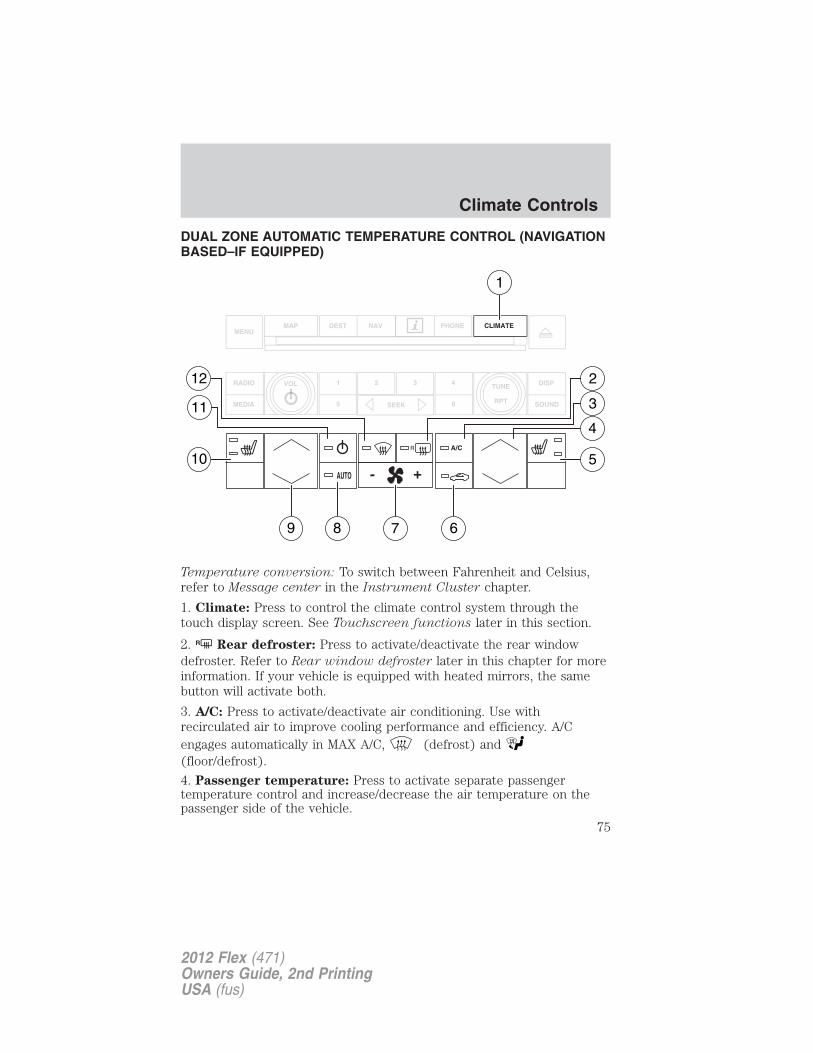
DUAL ZONE AUTOMATIC TEMPERATURE CONTROL (NAVIGATIONBASED–IF EQUIPPED)
Temperature conversion: To switch between Fahrenheit and Celsius,refer to Message center in the Instrument Cluster chapter.
1. Climate: Press to control the climate control system through thetouch display screen. See Touchscreen functions later in this section.
2. R Rear defroster: Press to activate/deactivate the rear windowdefroster. Refer to Rear window defroster later in this chapter for moreinformation. If your vehicle is equipped with heated mirrors, the samebutton will activate both.
3. A/C: Press to activate/deactivate air conditioning. Use withrecirculated air to improve cooling performance and efficiency. A/Cengages automatically in MAX A/C, (defrost) and(floor/defrost).
4. Passenger temperature: Press to activate separate passengertemperature control and increase/decrease the air temperature on thepassenger side of the vehicle.
Climate Controls
75
2012 Flex (471)Owners Guide, 2nd PrintingUSA (fus)
5. Passenger heated seat (if equipped): Press to control thepassenger heated seat. Refer to Front seating in the Seating and SafetyRestraints chapter for more information.
6. Recirculated air: Press to activate/deactivate air recirculation inthe vehicle. Recirculated air may reduce the amount of time needed tocool down the interior of the vehicle when used with A/C and may alsohelp reduce undesired odors from reaching the interior of the vehicle.Recirculated air engages automatically when MAX A/C is selected or canbe engaged manually in any airflow mode except (defrost).
Recirculation may turn off automatically in all airflow selections exceptMAX A/C.
7. – + Fan speed control: Press to decrease/increase the fan speed.
8. AUTO: Press to engage full automatic operation. Select the desiredtemperature using the temperature control. The system willautomatically determine fan speed, airflow location, A/C on or off, andoutside or recirculated air, to heat or cool the vehicle to reach thedesired temperature.
9. Driver temperature: Press to increase/decrease the air temperaturefor the driver side of the vehicle. This control also adjusts the passengerside temperature when dual zone operation is disengaged.
10. Driver heated seat (if equipped): Press to control the driverheated seat. Refer to Front seating in the Seating and SafetyRestraints chapter for more information.
11. Power: Press to activate/deactivate the climate control system.When the system is off, outside air is prevented from entering thevehicle. The climate status in the touchscreen will also be turned off.
12. Defrost: Distributes outside air through the windshielddefroster vents and de-mister vents. Can be used to clear the windshieldof fog and thin ice. The system will automatically provide outside air toreduce window fogging. Press this button again to return to the previousair flow selection.
Climate Controls
76
2012 Flex (471)Owners Guide, 2nd PrintingUSA (fus)
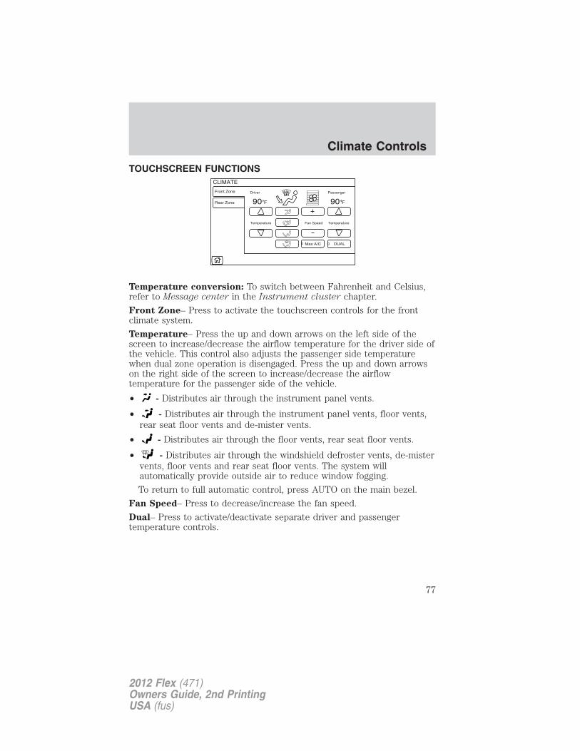
TOUCHSCREEN FUNCTIONS
Temperature conversion: To switch between Fahrenheit and Celsius,refer to Message center in the Instrument cluster chapter.
Front Zone– Press to activate the touchscreen controls for the frontclimate system.
Temperature– Press the up and down arrows on the left side of thescreen to increase/decrease the airflow temperature for the driver side ofthe vehicle. This control also adjusts the passenger side temperaturewhen dual zone operation is disengaged. Press the up and down arrowson the right side of the screen to increase/decrease the airflowtemperature for the passenger side of the vehicle.
• - Distributes air through the instrument panel vents.
• - Distributes air through the instrument panel vents, floor vents,rear seat floor vents and de-mister vents.
• - Distributes air through the floor vents, rear seat floor vents.
• - Distributes air through the windshield defroster vents, de-mistervents, floor vents and rear seat floor vents. The system willautomatically provide outside air to reduce window fogging.
To return to full automatic control, press AUTO on the main bezel.
Fan Speed– Press to decrease/increase the fan speed.
Dual– Press to activate/deactivate separate driver and passengertemperature controls.
Climate Controls
77
2012 Flex (471)Owners Guide, 2nd PrintingUSA (fus)
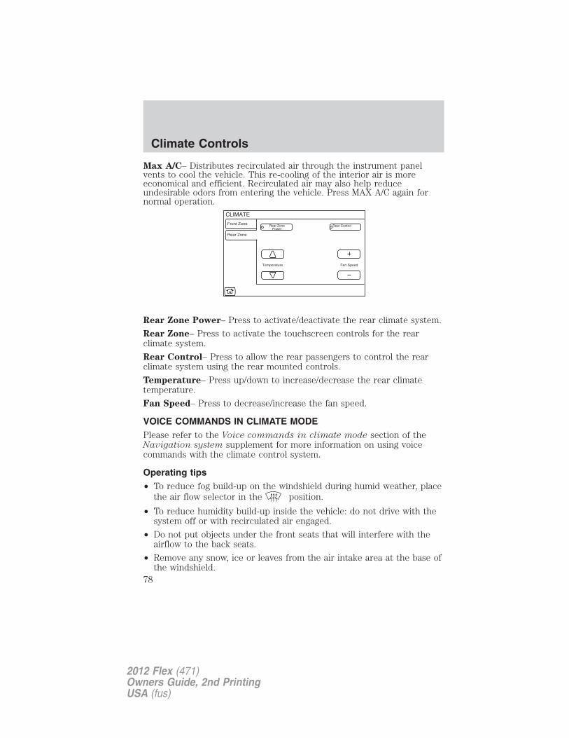
Max A/C– Distributes recirculated air through the instrument panelvents to cool the vehicle. This re-cooling of the interior air is moreeconomical and efficient. Recirculated air may also help reduceundesirable odors from entering the vehicle. Press MAX A/C again fornormal operation.
Rear Zone Power– Press to activate/deactivate the rear climate system.
Rear Zone– Press to activate the touchscreen controls for the rearclimate system.
Rear Control– Press to allow the rear passengers to control the rearclimate system using the rear mounted controls.
Temperature– Press up/down to increase/decrease the rear climatetemperature.
Fan Speed– Press to decrease/increase the fan speed.
VOICE COMMANDS IN CLIMATE MODEPlease refer to the Voice commands in climate mode section of theNavigation system supplement for more information on using voicecommands with the climate control system.
Operating tips• To reduce fog build-up on the windshield during humid weather, place
the air flow selector in the position.
• To reduce humidity build-up inside the vehicle: do not drive with thesystem off or with recirculated air engaged.
• Do not put objects under the front seats that will interfere with theairflow to the back seats.
• Remove any snow, ice or leaves from the air intake area at the base ofthe windshield.
Climate Controls
78
2012 Flex (471)Owners Guide, 2nd PrintingUSA (fus)
• To improve the A/C cool down, drive with the windows slightly openfor 2–3 minutes after starting the vehicle or until the vehicle has“aired out.”
• A small amount of air may be felt from the floor vent regardless of theair distribution setting that is selected.
In extremely cold temperatures, to maximize overall heater performanceit is suggested to not operate the auxiliary system (if equipped) until theengine temperature gauge crosses into the normal operating range.
For maximum cooling performance (MAX A/C):
1. Select MAX A/C. The system will default to single-zone operation andset the temperature to 60°F (16°C).
2. A/C, and will be selected.
3. Fan speed will be increased to the highest speed, but can be adjustedas desired.
To aid in side window defogging/demisting in cold weather:
1. Select .
2. Select A/C.
3. Adjust the temperature control to maintain comfort.
4. Set the fan to the highest speed.
5. Direct the outer instrument panel vents toward the side windows.
Climate Controls
79
2012 Flex (471)Owners Guide, 2nd PrintingUSA (fus)
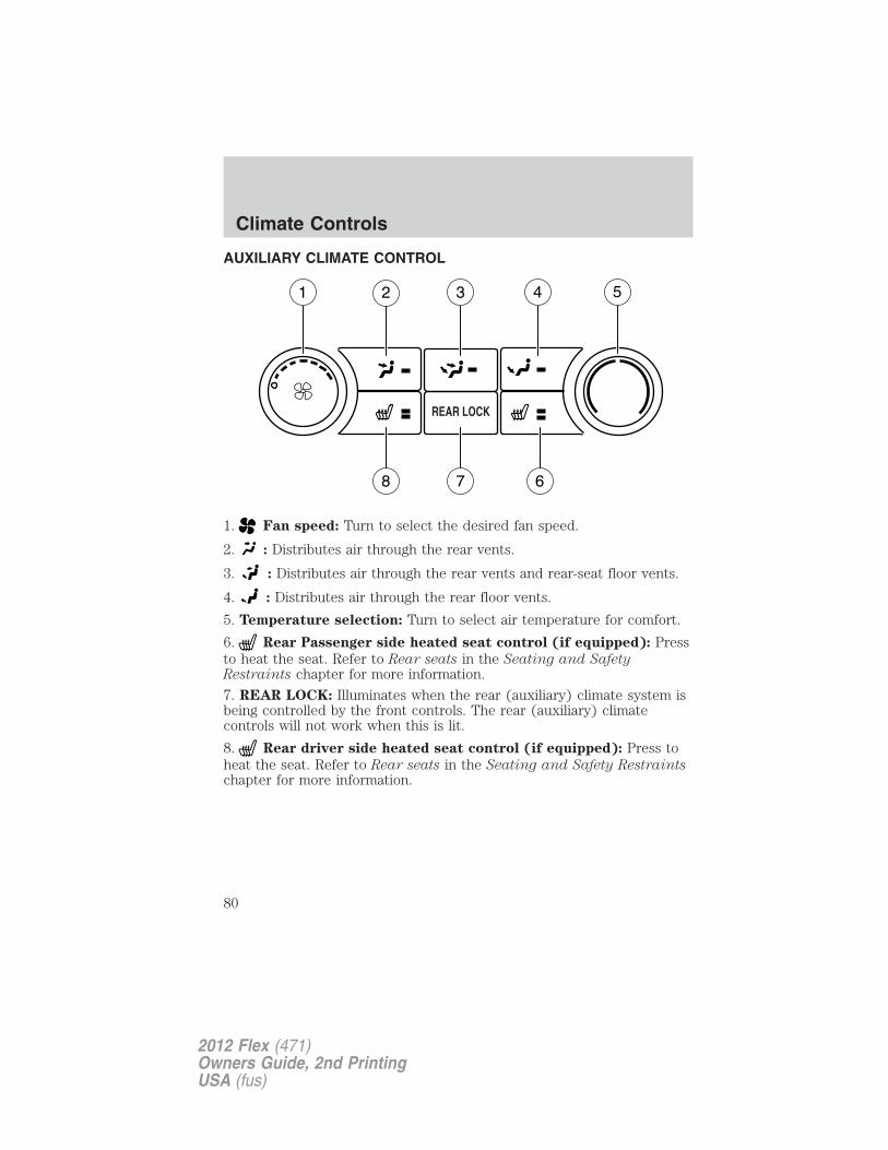
AUXILIARY CLIMATE CONTROL
1. Fan speed: Turn to select the desired fan speed.
2. : Distributes air through the rear vents.
3. : Distributes air through the rear vents and rear-seat floor vents.
4. : Distributes air through the rear floor vents.
5. Temperature selection: Turn to select air temperature for comfort.
6. Rear Passenger side heated seat control (if equipped): Pressto heat the seat. Refer to Rear seats in the Seating and SafetyRestraints chapter for more information.
7. REAR LOCK: Illuminates when the rear (auxiliary) climate system isbeing controlled by the front controls. The rear (auxiliary) climatecontrols will not work when this is lit.
8. Rear driver side heated seat control (if equipped): Press toheat the seat. Refer to Rear seats in the Seating and Safety Restraintschapter for more information.
Climate Controls
80
2012 Flex (471)Owners Guide, 2nd PrintingUSA (fus)
REAR WINDOW DEFROSTERR
The rear defroster control is located on the climate control panel andworks to clear the rear window of fog and thin ice.
The ignition must be on to operate the rear window defroster.
The rear defroster turns off automatically after 10 minutes or when theignition is turned off. To manually turn off the defroster before10 minutes have passed, press the control again.
Do not use razor blades or other sharp objects to clean the insideof the rear window or to remove decals from the inside of therear window. This may cause damage to the heated grid lines andwill not be covered by your warranty.
CABIN AIR FILTERYour vehicle is equipped with a cabin air filter, located behind the glovebox. The particulate air filtration system is designed to reduce theconcentration of airborne particles such as dust, spores and pollen in theair being supplied to the interior of the vehicle. This system provides thefollowing benefits:
• Improves driving comfort by reducing particle concentration.
• Improves the interior compartment cleanliness.
• Protects the climate control components from particle deposits.
Note: A cabin air filter must be installed at all times to prevent foreignobjects from entering the system. Running the system without a filter inplace could result in degradation or damage to the system.
For replacement intervals, refer to the Scheduled Maintenance chapter.For more information regarding your filter, see your authorized dealer.
Climate Controls
81
2012 Flex (471)Owners Guide, 2nd PrintingUSA (fus)
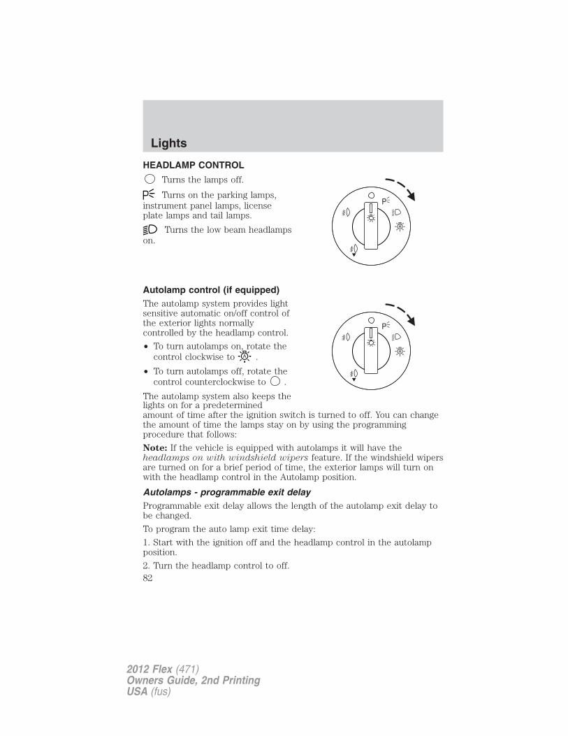
HEADLAMP CONTROL
Turns the lamps off.
Turns on the parking lamps,instrument panel lamps, licenseplate lamps and tail lamps.
Turns the low beam headlampson.
Autolamp control (if equipped)The autolamp system provides lightsensitive automatic on/off control ofthe exterior lights normallycontrolled by the headlamp control.
• To turn autolamps on, rotate thecontrol clockwise to .
• To turn autolamps off, rotate thecontrol counterclockwise to .
The autolamp system also keeps thelights on for a predeterminedamount of time after the ignition switch is turned to off. You can changethe amount of time the lamps stay on by using the programmingprocedure that follows:
Note: If the vehicle is equipped with autolamps it will have theheadlamps on with windshield wipers feature. If the windshield wipersare turned on for a brief period of time, the exterior lamps will turn onwith the headlamp control in the Autolamp position.
Autolamps - programmable exit delayProgrammable exit delay allows the length of the autolamp exit delay tobe changed.
To program the auto lamp exit time delay:
1. Start with the ignition off and the headlamp control in the autolampposition.
2. Turn the headlamp control to off.
Lights
82
2012 Flex (471)Owners Guide, 2nd PrintingUSA (fus)
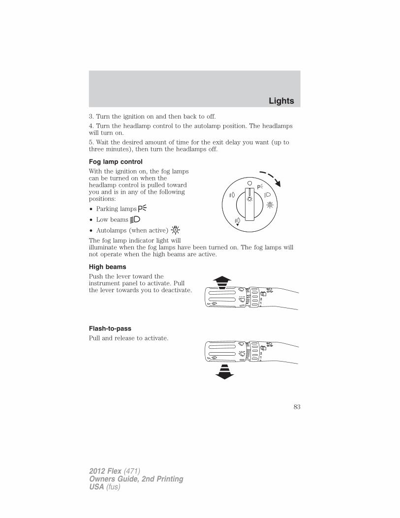
3. Turn the ignition on and then back to off.
4. Turn the headlamp control to the autolamp position. The headlampswill turn on.
5. Wait the desired amount of time for the exit delay you want (up tothree minutes), then turn the headlamps off.
Fog lamp controlWith the ignition on, the fog lampscan be turned on when theheadlamp control is pulled towardyou and is in any of the followingpositions:
• Parking lamps
• Low beams
• Autolamps (when active)
The fog lamp indicator light willilluminate when the fog lamps have been turned on. The fog lamps willnot operate when the high beams are active.
High beamsPush the lever toward theinstrument panel to activate. Pullthe lever towards you to deactivate.
Flash-to-passPull and release to activate.
12
12
Lights
83
2012 Flex (471)Owners Guide, 2nd PrintingUSA (fus)
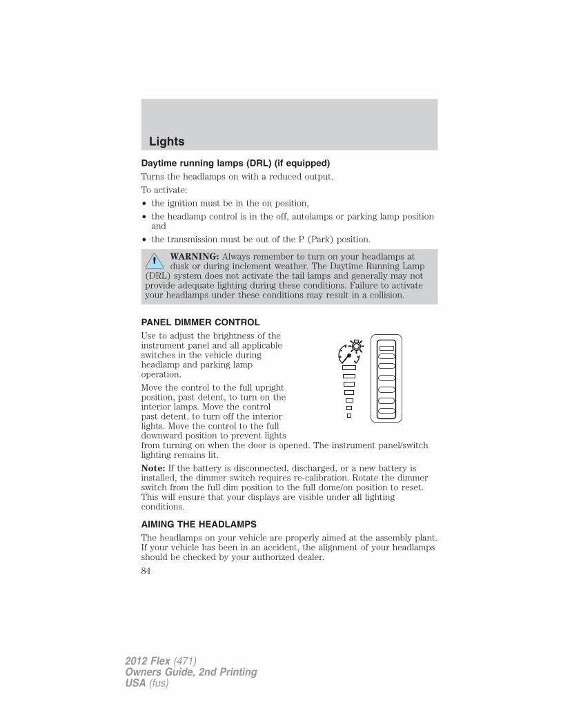
Daytime running lamps (DRL) (if equipped)Turns the headlamps on with a reduced output.
To activate:
• the ignition must be in the on position,
• the headlamp control is in the off, autolamps or parking lamp positionand
• the transmission must be out of the P (Park) position.
WARNING: Always remember to turn on your headlamps atdusk or during inclement weather. The Daytime Running Lamp
(DRL) system does not activate the tail lamps and generally may notprovide adequate lighting during these conditions. Failure to activateyour headlamps under these conditions may result in a collision.
PANEL DIMMER CONTROLUse to adjust the brightness of theinstrument panel and all applicableswitches in the vehicle duringheadlamp and parking lampoperation.
Move the control to the full uprightposition, past detent, to turn on theinterior lamps. Move the controlpast detent, to turn off the interiorlights. Move the control to the fulldownward position to prevent lightsfrom turning on when the door is opened. The instrument panel/switchlighting remains lit.
Note: If the battery is disconnected, discharged, or a new battery isinstalled, the dimmer switch requires re-calibration. Rotate the dimmerswitch from the full dim position to the full dome/on position to reset.This will ensure that your displays are visible under all lightingconditions.
AIMING THE HEADLAMPSThe headlamps on your vehicle are properly aimed at the assembly plant.If your vehicle has been in an accident, the alignment of your headlampsshould be checked by your authorized dealer.
Lights
84
2012 Flex (471)Owners Guide, 2nd PrintingUSA (fus)
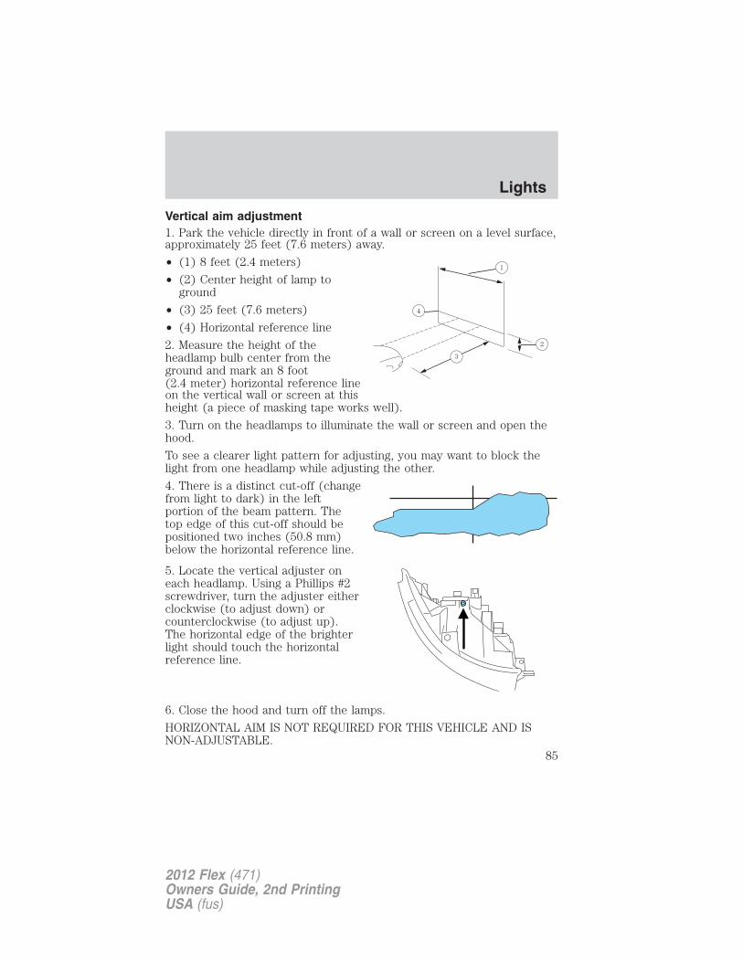
Vertical aim adjustment1. Park the vehicle directly in front of a wall or screen on a level surface,approximately 25 feet (7.6 meters) away.
• (1) 8 feet (2.4 meters)
• (2) Center height of lamp toground
• (3) 25 feet (7.6 meters)
• (4) Horizontal reference line
2. Measure the height of theheadlamp bulb center from theground and mark an 8 foot(2.4 meter) horizontal reference lineon the vertical wall or screen at thisheight (a piece of masking tape works well).
3. Turn on the headlamps to illuminate the wall or screen and open thehood.
To see a clearer light pattern for adjusting, you may want to block thelight from one headlamp while adjusting the other.
4. There is a distinct cut-off (changefrom light to dark) in the leftportion of the beam pattern. Thetop edge of this cut-off should bepositioned two inches (50.8 mm)below the horizontal reference line.
5. Locate the vertical adjuster oneach headlamp. Using a Phillips #2screwdriver, turn the adjuster eitherclockwise (to adjust down) orcounterclockwise (to adjust up).The horizontal edge of the brighterlight should touch the horizontalreference line.
6. Close the hood and turn off the lamps.
HORIZONTAL AIM IS NOT REQUIRED FOR THIS VEHICLE AND ISNON-ADJUSTABLE.
Lights
85
2012 Flex (471)Owners Guide, 2nd PrintingUSA (fus)
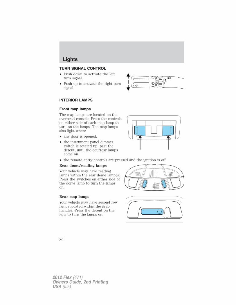
TURN SIGNAL CONTROL• Push down to activate the left
turn signal.
• Push up to activate the right turnsignal.
INTERIOR LAMPS
Front map lampsThe map lamps are located on theoverhead console. Press the controlson either side of each map lamp toturn on the lamps. The map lampsalso light when:
• any door is opened.
• the instrument panel dimmerswitch is rotated up, past thedetent, until the courtesy lampscome on.
• the remote entry controls are pressed and the ignition is off.
Rear dome/reading lamps
Your vehicle may have readinglamps within the rear dome lamp(s).Press the switches on either side ofthe dome lamp to turn the lampson.
Rear map lamps
Your vehicle may have second rowlamps located within the grabhandles. Press the detent on thelens to turn the lamps on.
12
Lights
86
2012 Flex (471)Owners Guide, 2nd PrintingUSA (fus)
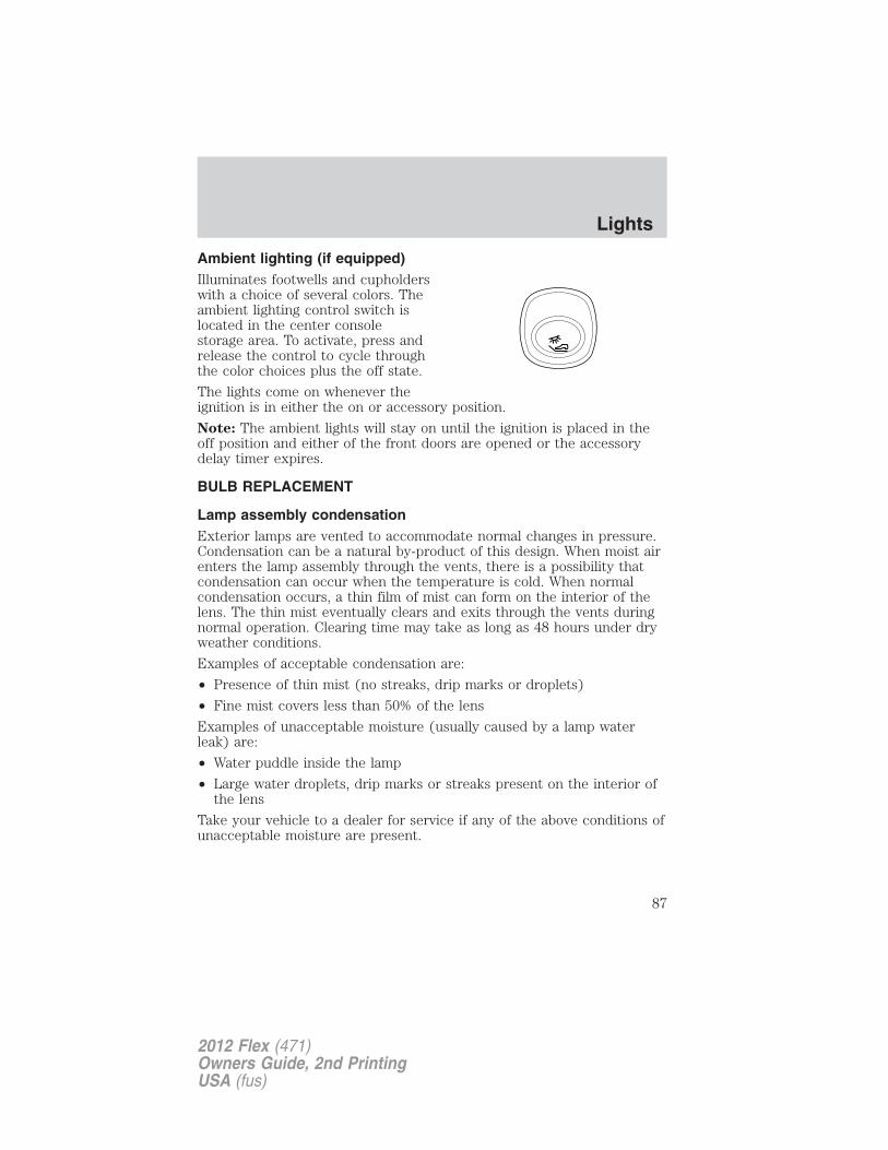
Ambient lighting (if equipped)Illuminates footwells and cupholderswith a choice of several colors. Theambient lighting control switch islocated in the center consolestorage area. To activate, press andrelease the control to cycle throughthe color choices plus the off state.
The lights come on whenever theignition is in either the on or accessory position.
Note: The ambient lights will stay on until the ignition is placed in theoff position and either of the front doors are opened or the accessorydelay timer expires.
BULB REPLACEMENT
Lamp assembly condensationExterior lamps are vented to accommodate normal changes in pressure.Condensation can be a natural by-product of this design. When moist airenters the lamp assembly through the vents, there is a possibility thatcondensation can occur when the temperature is cold. When normalcondensation occurs, a thin film of mist can form on the interior of thelens. The thin mist eventually clears and exits through the vents duringnormal operation. Clearing time may take as long as 48 hours under dryweather conditions.
Examples of acceptable condensation are:
• Presence of thin mist (no streaks, drip marks or droplets)
• Fine mist covers less than 50% of the lens
Examples of unacceptable moisture (usually caused by a lamp waterleak) are:
• Water puddle inside the lamp
• Large water droplets, drip marks or streaks present on the interior ofthe lens
Take your vehicle to a dealer for service if any of the above conditions ofunacceptable moisture are present.
Lights
87
2012 Flex (471)Owners Guide, 2nd PrintingUSA (fus)
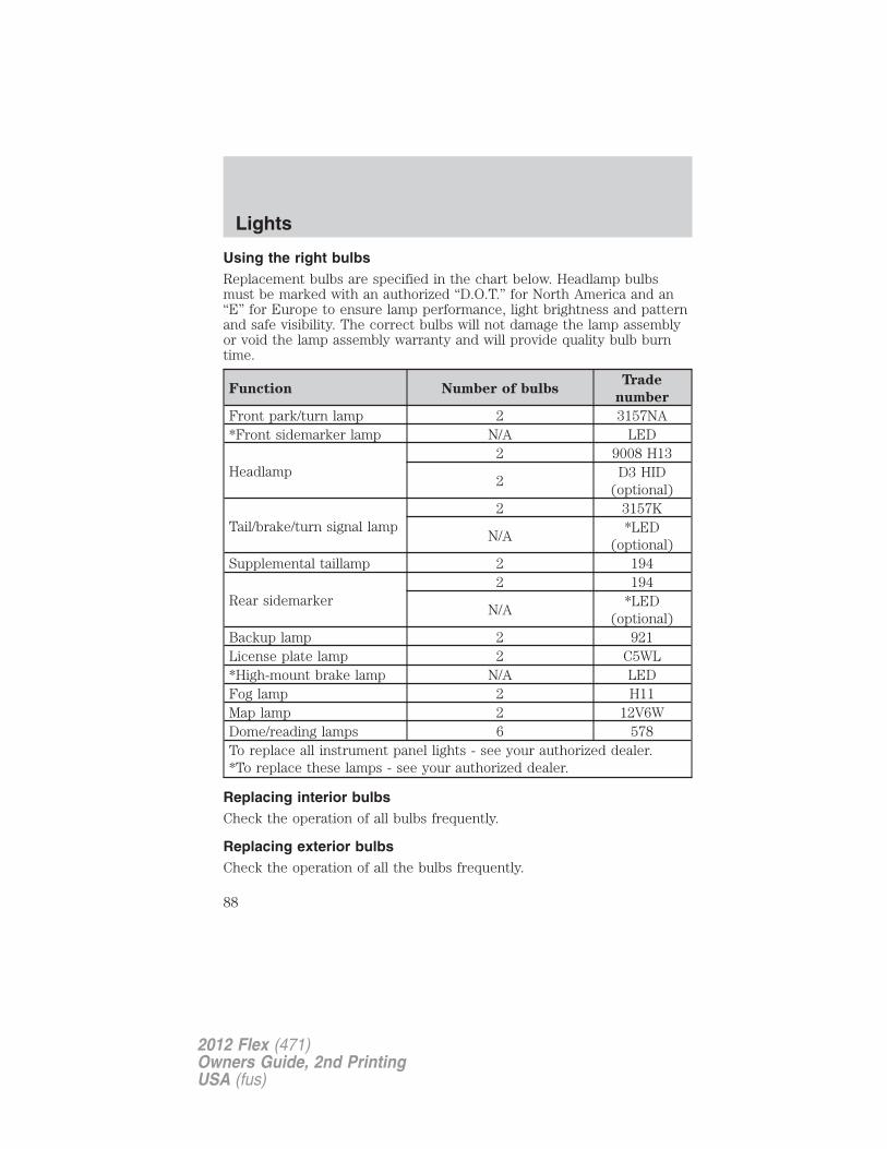
Using the right bulbsReplacement bulbs are specified in the chart below. Headlamp bulbsmust be marked with an authorized “D.O.T.” for North America and an“E” for Europe to ensure lamp performance, light brightness and patternand safe visibility. The correct bulbs will not damage the lamp assemblyor void the lamp assembly warranty and will provide quality bulb burntime.
Function Number of bulbsTrade
number
Front park/turn lamp 2 3157NA*Front sidemarker lamp N/A LED
Headlamp2 9008 H13
2D3 HID
(optional)
Tail/brake/turn signal lamp2 3157K
N/A*LED
(optional)Supplemental taillamp 2 194
Rear sidemarker2 194
N/A*LED
(optional)Backup lamp 2 921License plate lamp 2 C5WL*High-mount brake lamp N/A LEDFog lamp 2 H11Map lamp 2 12V6WDome/reading lamps 6 578To replace all instrument panel lights - see your authorized dealer.*To replace these lamps - see your authorized dealer.
Replacing interior bulbsCheck the operation of all bulbs frequently.
Replacing exterior bulbsCheck the operation of all the bulbs frequently.
Lights
88
2012 Flex (471)Owners Guide, 2nd PrintingUSA (fus)
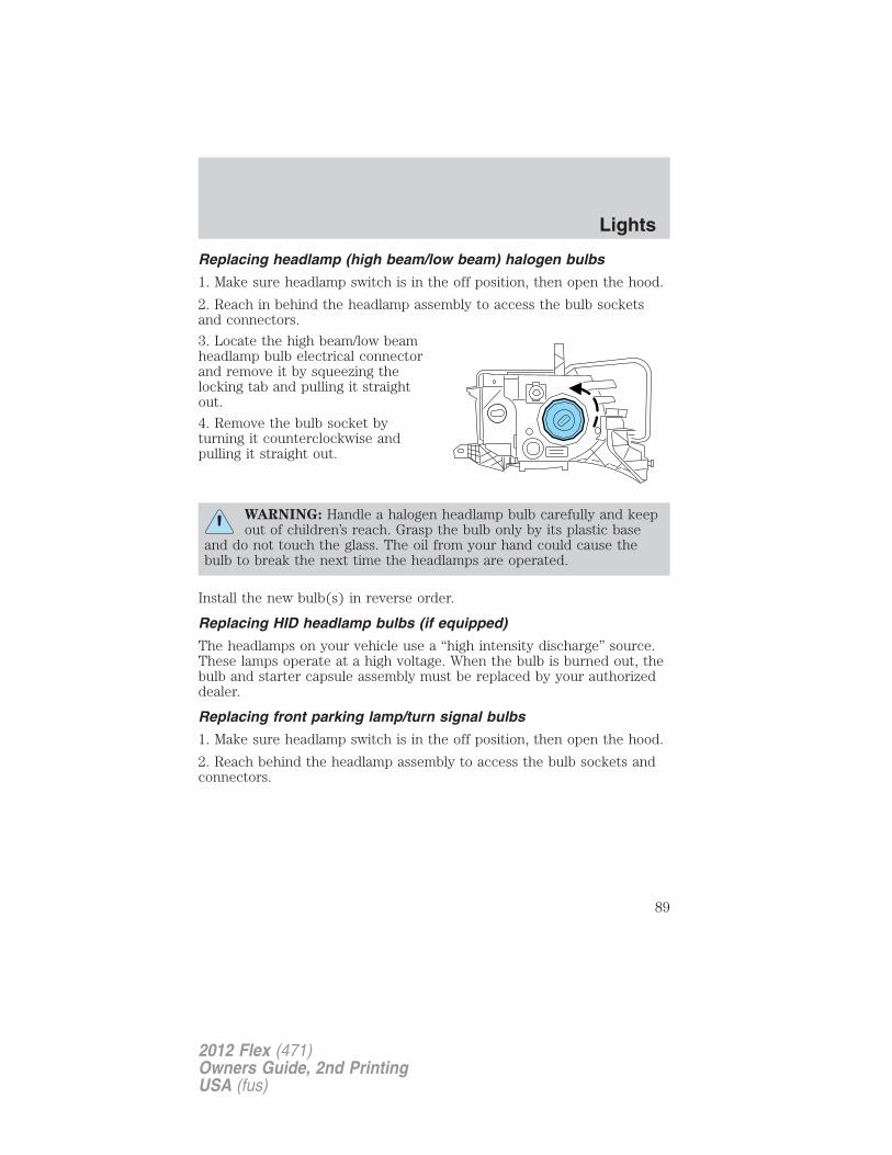
Replacing headlamp (high beam/low beam) halogen bulbs
1. Make sure headlamp switch is in the off position, then open the hood.
2. Reach in behind the headlamp assembly to access the bulb socketsand connectors.
3. Locate the high beam/low beamheadlamp bulb electrical connectorand remove it by squeezing thelocking tab and pulling it straightout.
4. Remove the bulb socket byturning it counterclockwise andpulling it straight out.
WARNING: Handle a halogen headlamp bulb carefully and keepout of children’s reach. Grasp the bulb only by its plastic base
and do not touch the glass. The oil from your hand could cause thebulb to break the next time the headlamps are operated.
Install the new bulb(s) in reverse order.
Replacing HID headlamp bulbs (if equipped)
The headlamps on your vehicle use a “high intensity discharge” source.These lamps operate at a high voltage. When the bulb is burned out, thebulb and starter capsule assembly must be replaced by your authorizeddealer.
Replacing front parking lamp/turn signal bulbs
1. Make sure headlamp switch is in the off position, then open the hood.
2. Reach behind the headlamp assembly to access the bulb sockets andconnectors.
Lights
89
2012 Flex (471)Owners Guide, 2nd PrintingUSA (fus)
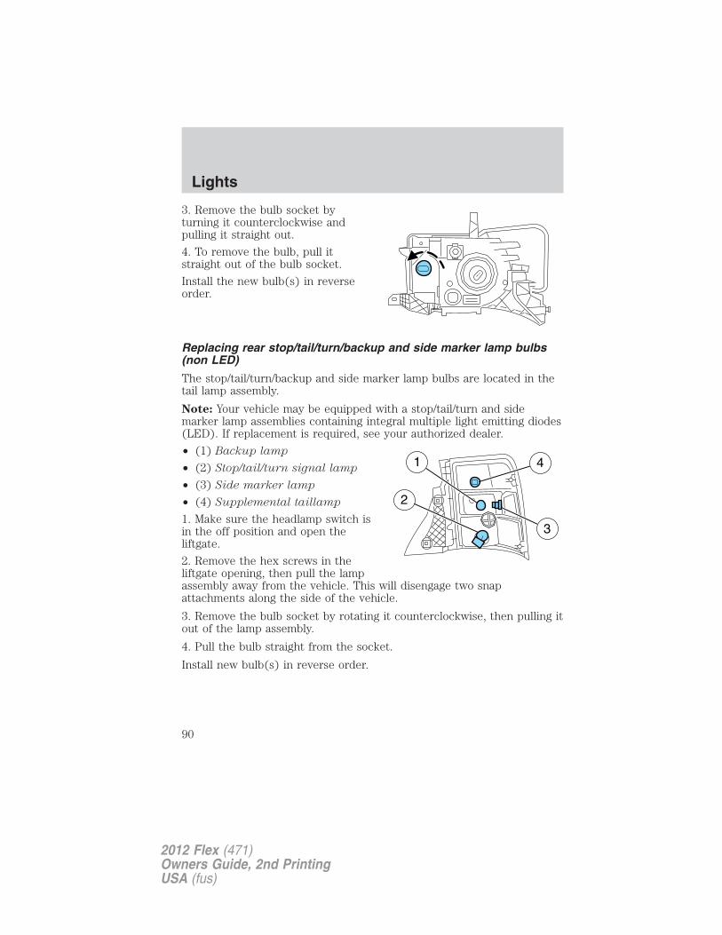
3. Remove the bulb socket byturning it counterclockwise andpulling it straight out.
4. To remove the bulb, pull itstraight out of the bulb socket.
Install the new bulb(s) in reverseorder.
Replacing rear stop/tail/turn/backup and side marker lamp bulbs(non LED)
The stop/tail/turn/backup and side marker lamp bulbs are located in thetail lamp assembly.
Note: Your vehicle may be equipped with a stop/tail/turn and sidemarker lamp assemblies containing integral multiple light emitting diodes(LED). If replacement is required, see your authorized dealer.
• (1) Backup lamp
• (2) Stop/tail/turn signal lamp
• (3) Side marker lamp
• (4) Supplemental taillamp
1. Make sure the headlamp switch isin the off position and open theliftgate.
2. Remove the hex screws in theliftgate opening, then pull the lampassembly away from the vehicle. This will disengage two snapattachments along the side of the vehicle.
3. Remove the bulb socket by rotating it counterclockwise, then pulling itout of the lamp assembly.
4. Pull the bulb straight from the socket.
Install new bulb(s) in reverse order.
Lights
90
2012 Flex (471)Owners Guide, 2nd PrintingUSA (fus)
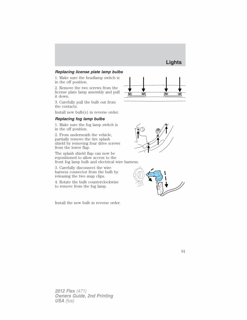
Replacing license plate lamp bulbs1. Make sure the headlamp switch isin the off position.
2. Remove the two screws from thelicense plate lamp assembly and pullit down.
3. Carefully pull the bulb out fromthe contacts.
Install new bulb(s) in reverse order.
Replacing fog lamp bulbs1. Make sure the fog lamp switch isin the off position.
2. From underneath the vehicle,partially remove the tire splashshield by removing four drive screwsfrom the lower flap.
The splash shield flap can now berepositioned to allow access to thefront fog lamp bulb and electrical wire harness.
3. Carefully disconnect the wireharness connector from the bulb byreleasing the two snap clips.
4. Rotate the bulb counterclockwiseto remove from the fog lamp.
Install the new bulb in reverse order.
Lights
91
2012 Flex (471)Owners Guide, 2nd PrintingUSA (fus)
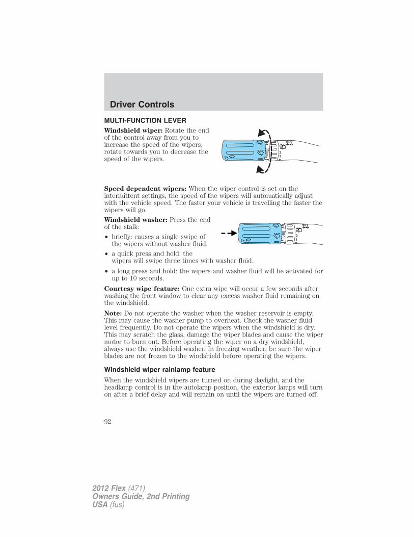
MULTI-FUNCTION LEVERWindshield wiper: Rotate the endof the control away from you toincrease the speed of the wipers;rotate towards you to decrease thespeed of the wipers.
Speed dependent wipers: When the wiper control is set on theintermittent settings, the speed of the wipers will automatically adjustwith the vehicle speed. The faster your vehicle is travelling the faster thewipers will go.
Windshield washer: Press the endof the stalk:
• briefly: causes a single swipe ofthe wipers without washer fluid.
• a quick press and hold: thewipers will swipe three times with washer fluid.
• a long press and hold: the wipers and washer fluid will be activated forup to 10 seconds.
Courtesy wipe feature: One extra wipe will occur a few seconds afterwashing the front window to clear any excess washer fluid remaining onthe windshield.
Note: Do not operate the washer when the washer reservoir is empty.This may cause the washer pump to overheat. Check the washer fluidlevel frequently. Do not operate the wipers when the windshield is dry.This may scratch the glass, damage the wiper blades and cause the wipermotor to burn out. Before operating the wiper on a dry windshield,always use the windshield washer. In freezing weather, be sure the wiperblades are not frozen to the windshield before operating the wipers.
Windshield wiper rainlamp feature
When the windshield wipers are turned on during daylight, and theheadlamp control is in the autolamp position, the exterior lamps will turnon after a brief delay and will remain on until the wipers are turned off.
12
Driver Controls
92
2012 Flex (471)Owners Guide, 2nd PrintingUSA (fus)
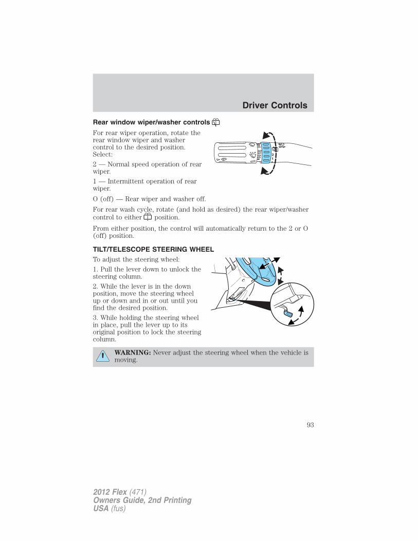
Rear window wiper/washer controls
For rear wiper operation, rotate therear window wiper and washercontrol to the desired position.Select:
2 — Normal speed operation of rearwiper.
1 — Intermittent operation of rearwiper.
O (off) — Rear wiper and washer off.
For rear wash cycle, rotate (and hold as desired) the rear wiper/washercontrol to either position.
From either position, the control will automatically return to the 2 or O(off) position.
TILT/TELESCOPE STEERING WHEELTo adjust the steering wheel:
1. Pull the lever down to unlock thesteering column.
2. While the lever is in the downposition, move the steering wheelup or down and in or out until youfind the desired position.
3. While holding the steering wheelin place, pull the lever up to itsoriginal position to lock the steeringcolumn.
WARNING: Never adjust the steering wheel when the vehicle ismoving.
12
Driver Controls
93
2012 Flex (471)Owners Guide, 2nd PrintingUSA (fus)
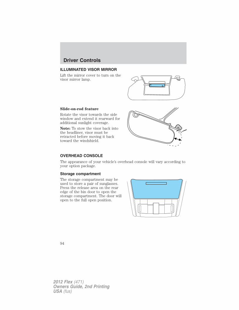
ILLUMINATED VISOR MIRRORLift the mirror cover to turn on thevisor mirror lamp.
Slide-on-rod feature
Rotate the visor towards the sidewindow and extend it rearward foradditional sunlight coverage.
Note: To stow the visor back intothe headliner, visor must beretracted before moving it backtoward the windshield.
OVERHEAD CONSOLE
The appearance of your vehicle’s overhead console will vary according toyour option package.
Storage compartmentThe storage compartment may beused to store a pair of sunglasses.Press the release area on the rearedge of the bin door to open thestorage compartment. The door willopen to the full open position.
Driver Controls
94
2012 Flex (471)Owners Guide, 2nd PrintingUSA (fus)
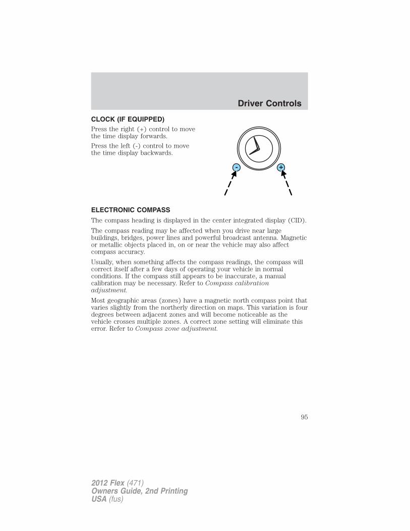
CLOCK (IF EQUIPPED)Press the right (+) control to movethe time display forwards.
Press the left (-) control to movethe time display backwards.
ELECTRONIC COMPASS
The compass heading is displayed in the center integrated display (CID).
The compass reading may be affected when you drive near largebuildings, bridges, power lines and powerful broadcast antenna. Magneticor metallic objects placed in, on or near the vehicle may also affectcompass accuracy.
Usually, when something affects the compass readings, the compass willcorrect itself after a few days of operating your vehicle in normalconditions. If the compass still appears to be inaccurate, a manualcalibration may be necessary. Refer to Compass calibrationadjustment.
Most geographic areas (zones) have a magnetic north compass point thatvaries slightly from the northerly direction on maps. This variation is fourdegrees between adjacent zones and will become noticeable as thevehicle crosses multiple zones. A correct zone setting will eliminate thiserror. Refer to Compass zone adjustment.
Driver Controls
95
2012 Flex (471)Owners Guide, 2nd PrintingUSA (fus)
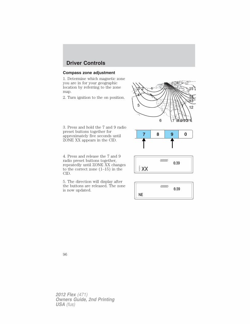
Compass zone adjustment1. Determine which magnetic zoneyou are in for your geographiclocation by referring to the zonemap.
2. Turn ignition to the on position.
3. Press and hold the 7 and 9 radiopreset buttons together forapproximately five seconds untilZONE XX appears in the CID.
4. Press and release the 7 and 9radio preset buttons together,repeatedly until ZONE XX changesto the correct zone (1–15) in theCID.
5. The direction will display afterthe buttons are released. The zoneis now updated.
123
4
5
6 7 8 91011
12
1314
15
Driver Controls
96
2012 Flex (471)Owners Guide, 2nd PrintingUSA (fus)
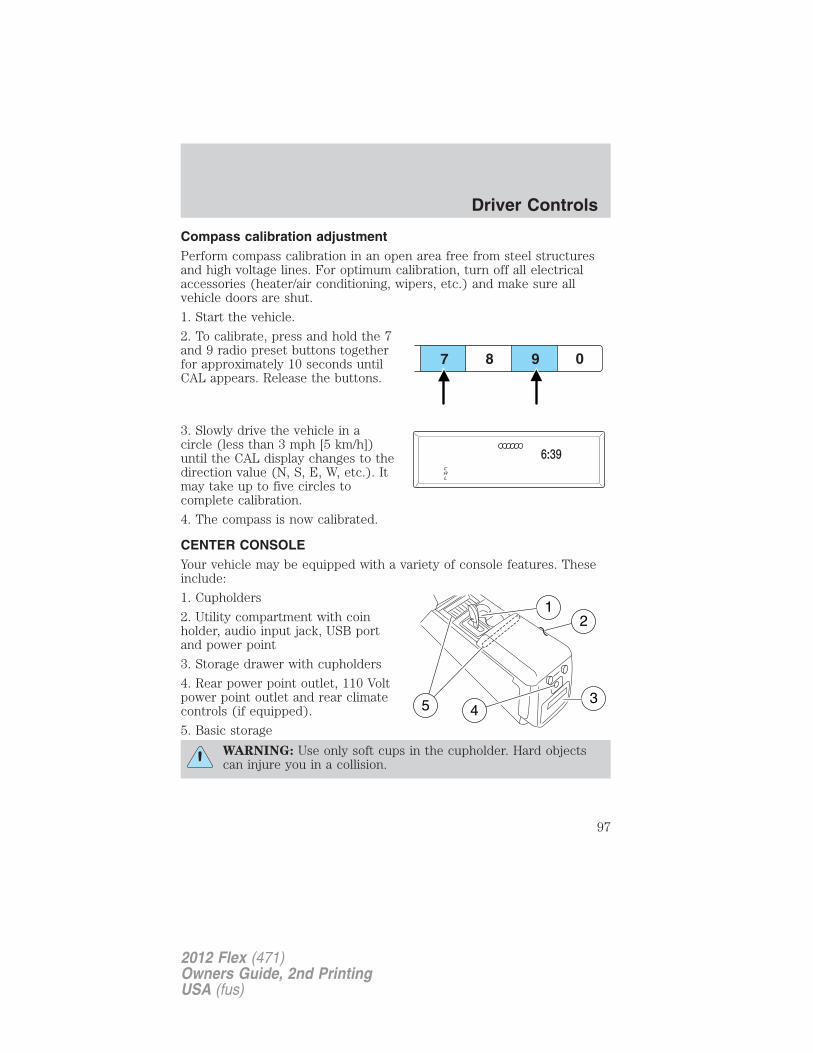
Compass calibration adjustmentPerform compass calibration in an open area free from steel structuresand high voltage lines. For optimum calibration, turn off all electricalaccessories (heater/air conditioning, wipers, etc.) and make sure allvehicle doors are shut.
1. Start the vehicle.
2. To calibrate, press and hold the 7and 9 radio preset buttons togetherfor approximately 10 seconds untilCAL appears. Release the buttons.
3. Slowly drive the vehicle in acircle (less than 3 mph [5 km/h])until the CAL display changes to thedirection value (N, S, E, W, etc.). Itmay take up to five circles tocomplete calibration.
4. The compass is now calibrated.
CENTER CONSOLEYour vehicle may be equipped with a variety of console features. Theseinclude:
1. Cupholders
2. Utility compartment with coinholder, audio input jack, USB portand power point
3. Storage drawer with cupholders
4. Rear power point outlet, 110 Voltpower point outlet and rear climatecontrols (if equipped).
5. Basic storage
WARNING: Use only soft cups in the cupholder. Hard objectscan injure you in a collision.
Driver Controls
97
2012 Flex (471)Owners Guide, 2nd PrintingUSA (fus)
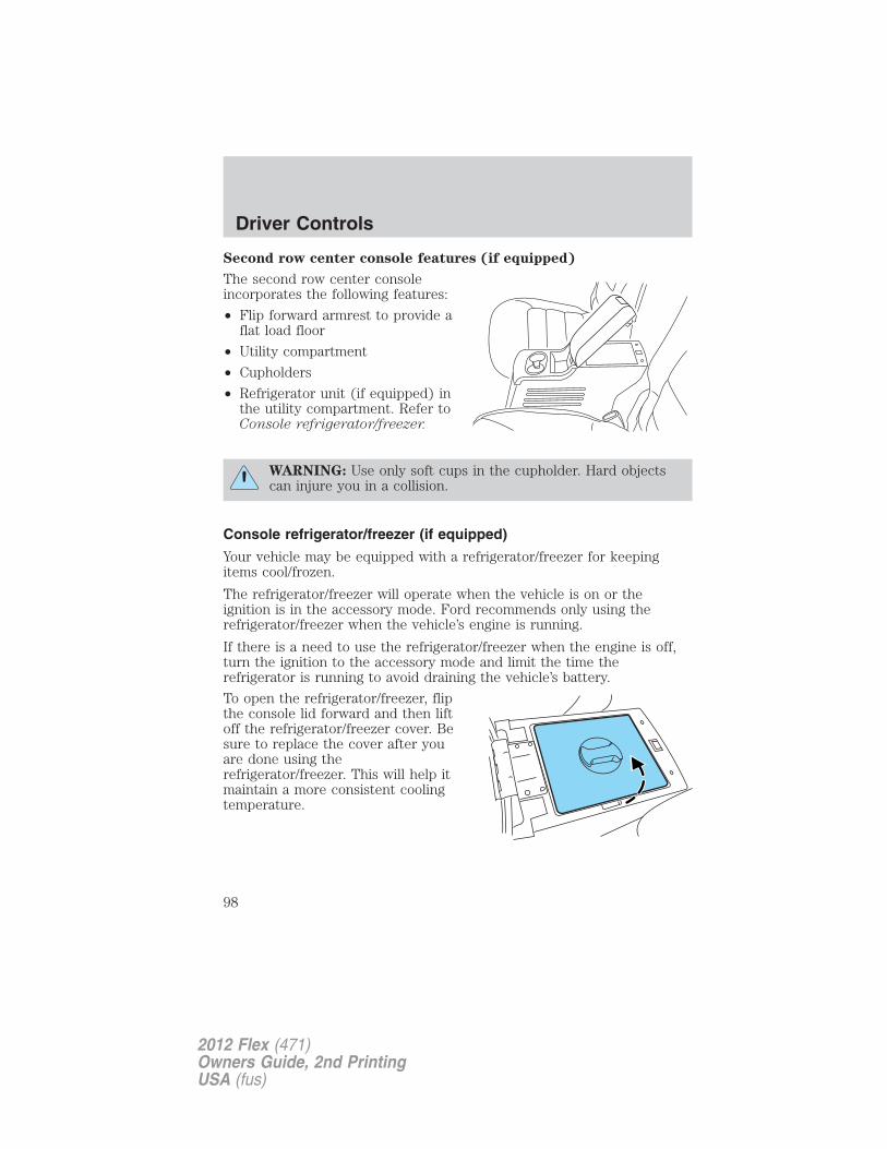
Second row center console features (if equipped)
The second row center consoleincorporates the following features:
• Flip forward armrest to provide aflat load floor
• Utility compartment
• Cupholders
• Refrigerator unit (if equipped) inthe utility compartment. Refer toConsole refrigerator/freezer.
WARNING: Use only soft cups in the cupholder. Hard objectscan injure you in a collision.
Console refrigerator/freezer (if equipped)
Your vehicle may be equipped with a refrigerator/freezer for keepingitems cool/frozen.
The refrigerator/freezer will operate when the vehicle is on or theignition is in the accessory mode. Ford recommends only using therefrigerator/freezer when the vehicle’s engine is running.
If there is a need to use the refrigerator/freezer when the engine is off,turn the ignition to the accessory mode and limit the time therefrigerator is running to avoid draining the vehicle’s battery.
To open the refrigerator/freezer, flipthe console lid forward and then liftoff the refrigerator/freezer cover. Besure to replace the cover after youare done using therefrigerator/freezer. This will help itmaintain a more consistent coolingtemperature.
Driver Controls
98
2012 Flex (471)Owners Guide, 2nd PrintingUSA (fus)
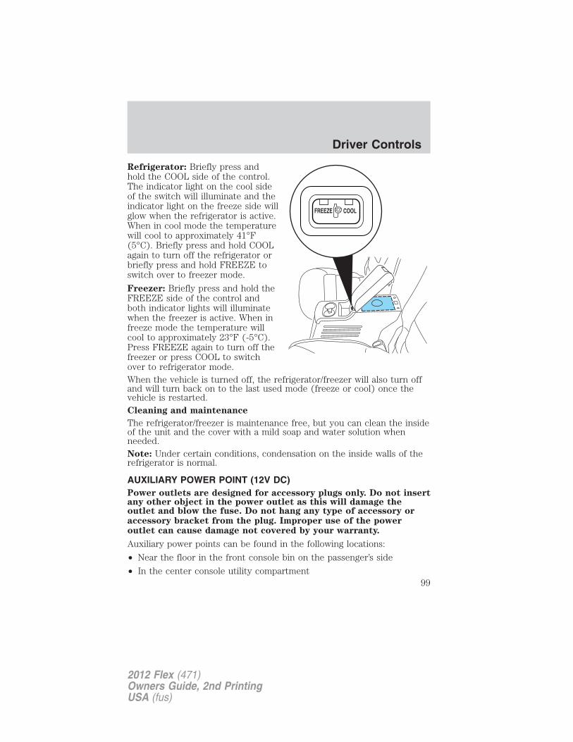
Refrigerator: Briefly press andhold the COOL side of the control.The indicator light on the cool sideof the switch will illuminate and theindicator light on the freeze side willglow when the refrigerator is active.When in cool mode the temperaturewill cool to approximately 41°F(5°C). Briefly press and hold COOLagain to turn off the refrigerator orbriefly press and hold FREEZE toswitch over to freezer mode.
Freezer: Briefly press and hold theFREEZE side of the control andboth indicator lights will illuminatewhen the freezer is active. When infreeze mode the temperature willcool to approximately 23°F (-5°C).Press FREEZE again to turn off thefreezer or press COOL to switchover to refrigerator mode.When the vehicle is turned off, the refrigerator/freezer will also turn offand will turn back on to the last used mode (freeze or cool) once thevehicle is restarted.Cleaning and maintenance
The refrigerator/freezer is maintenance free, but you can clean the insideof the unit and the cover with a mild soap and water solution whenneeded.Note: Under certain conditions, condensation on the inside walls of therefrigerator is normal.
AUXILIARY POWER POINT (12V DC)Power outlets are designed for accessory plugs only. Do not insertany other object in the power outlet as this will damage theoutlet and blow the fuse. Do not hang any type of accessory oraccessory bracket from the plug. Improper use of the poweroutlet can cause damage not covered by your warranty.
Auxiliary power points can be found in the following locations:
• Near the floor in the front console bin on the passenger’s side
• In the center console utility compartment
Driver Controls
99
2012 Flex (471)Owners Guide, 2nd PrintingUSA (fus)
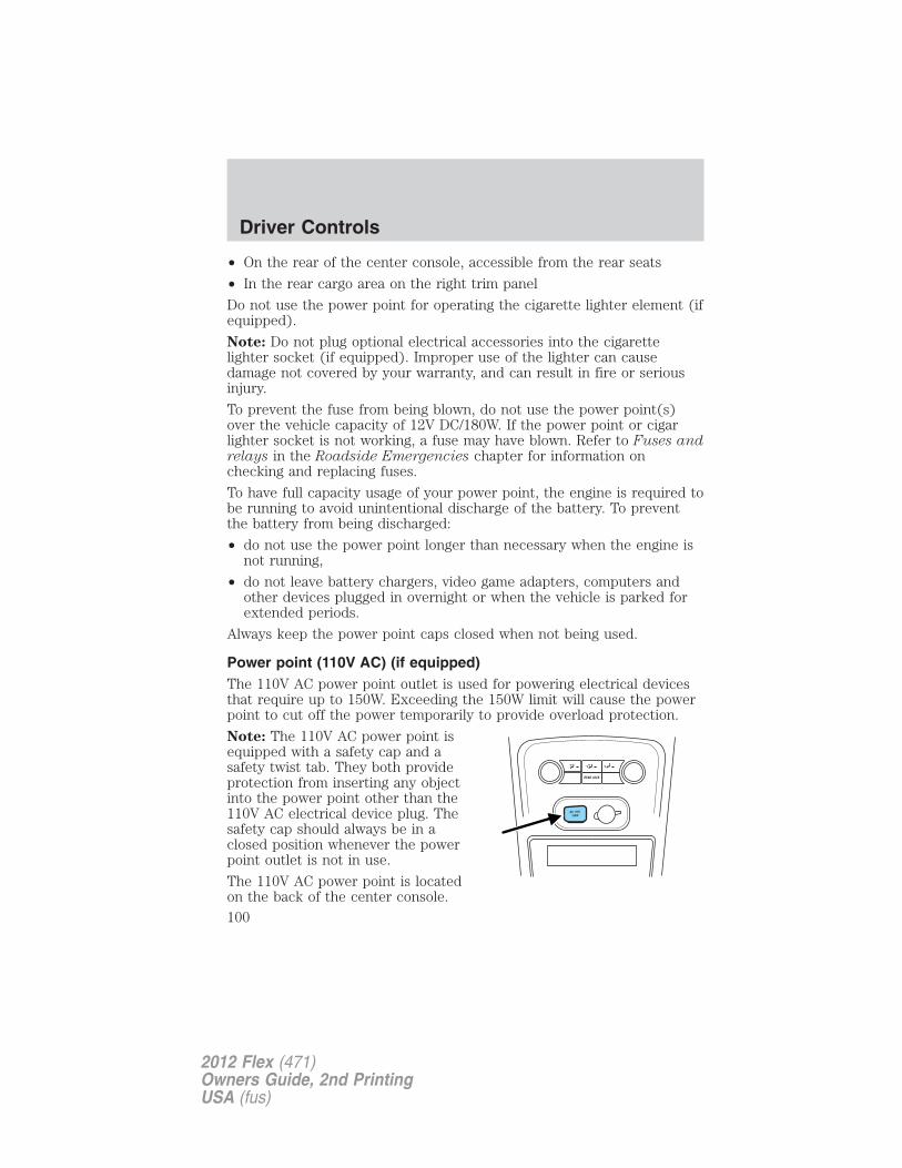
• On the rear of the center console, accessible from the rear seats
• In the rear cargo area on the right trim panel
Do not use the power point for operating the cigarette lighter element (ifequipped).
Note: Do not plug optional electrical accessories into the cigarettelighter socket (if equipped). Improper use of the lighter can causedamage not covered by your warranty, and can result in fire or seriousinjury.
To prevent the fuse from being blown, do not use the power point(s)over the vehicle capacity of 12V DC/180W. If the power point or cigarlighter socket is not working, a fuse may have blown. Refer to Fuses andrelays in the Roadside Emergencies chapter for information onchecking and replacing fuses.
To have full capacity usage of your power point, the engine is required tobe running to avoid unintentional discharge of the battery. To preventthe battery from being discharged:
• do not use the power point longer than necessary when the engine isnot running,
• do not leave battery chargers, video game adapters, computers andother devices plugged in overnight or when the vehicle is parked forextended periods.
Always keep the power point caps closed when not being used.
Power point (110V AC) (if equipped)The 110V AC power point outlet is used for powering electrical devicesthat require up to 150W. Exceeding the 150W limit will cause the powerpoint to cut off the power temporarily to provide overload protection.
Note: The 110V AC power point isequipped with a safety cap and asafety twist tab. They both provideprotection from inserting any objectinto the power point other than the110V AC electrical device plug. Thesafety cap should always be in aclosed position whenever the powerpoint outlet is not in use.
The 110V AC power point is locatedon the back of the center console.
Driver Controls
100
2012 Flex (471)Owners Guide, 2nd PrintingUSA (fus)
The power outlet is not designed for the following electric appliances;they may not work properly:
• Cathode ray tube type televisions.
• Motor loads, such as vacuum cleaners, electric saws and other electricpower tools, compressor-driven refrigerators, etc.
• Measuring devices, which process precise data, such as medicalequipment, measuring equipment, etc.
• Other appliances requiring an extremely stable power supply:microcomputer-controlled electric blankets, touch sensor lamps, etc.
WARNING: Do not keep electrical devices plugged in the powerpoint whenever the device is not in use. Do not use any
extension cord with the 110V AC power point, since it will defeat thesafety protection design provided by the cap and twist tab. Doing somy cause the power point to overload due to powering multipledevices that can reach beyond the 150W load limit and could result infire or serious injury.
The power point can switch to a fault mode when it is overloaded,overheated, or shorted. For overloading and shorting conditions, unplugyour device and turn the ignition key off then on. For an overheatingcondition, let the system cool off, then turn the ignition key off then on.
The 110V AC power point can provide power whenever the vehicleignition is in the run position and the power point green indicator lightlocated in the top left corner is turned on. Refer to the indicator lightcode below for the power point status.
Indicator light code
Green light is on — Power point is ready to supply power
Green light is off — Power point power supply is off. Ignition is not inRUN position
Green light is blinking — Power point is in fault mode
Driver Controls
101
2012 Flex (471)Owners Guide, 2nd PrintingUSA (fus)
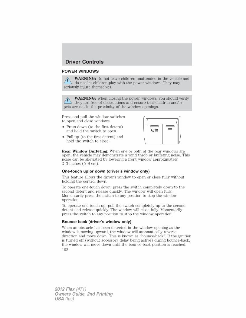
POWER WINDOWS
WARNING: Do not leave children unattended in the vehicle anddo not let children play with the power windows. They may
seriously injure themselves.
WARNING: When closing the power windows, you should verifythey are free of obstructions and ensure that children and/or
pets are not in the proximity of the window openings.
Press and pull the window switchesto open and close windows.
• Press down (to the first detent)and hold the switch to open.
• Pull up (to the first detent) andhold the switch to close.
Rear Window Buffeting: When one or both of the rear windows areopen, the vehicle may demonstrate a wind throb or buffeting noise. Thisnoise can be alleviated by lowering a front window approximately2–3 inches (5–8 cm).
One-touch up or down (driver’s window only)This feature allows the driver’s window to open or close fully withoutholding the control down.
To operate one-touch down, press the switch completely down to thesecond detent and release quickly. The window will open fully.Momentarily press the switch to any position to stop the windowoperation.
To operate one-touch up, pull the switch completely up to the seconddetent and release quickly. The window will close fully. Momentarilypress the switch to any position to stop the window operation.
Bounce-back (driver’s window only)When an obstacle has been detected in the window opening as thewindow is moving upward, the window will automatically reversedirection and move down. This is known as “bounce-back”. If the ignitionis turned off (without accessory delay being active) during bounce-back,the window will move down until the bounce-back position is reached.
AUTO
Driver Controls
102
2012 Flex (471)Owners Guide, 2nd PrintingUSA (fus)
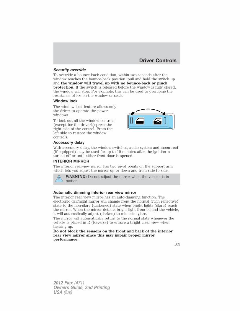
Security overrideTo override a bounce-back condition, within two seconds after thewindow reaches the bounce-back position, pull and hold the switch upand the window will travel up with no bounce-back or pinchprotection. If the switch is released before the window is fully closed,the window will stop. For example, this can be used to overcome theresistance of ice on the window or seals.
Window lockThe window lock feature allows onlythe driver to operate the powerwindows.
To lock out all the window controls(except for the driver’s) press theright side of the control. Press theleft side to restore the windowcontrols.
Accessory delayWith accessory delay, the window switches, audio system and moon roof(if equipped) may be used for up to 10 minutes after the ignition isturned off or until either front door is opened.
INTERIOR MIRRORThe interior rearview mirror has two pivot points on the support armwhich lets you adjust the mirror up or down and from side to side.
WARNING: Do not adjust the mirror while the vehicle is inmotion.
Automatic dimming interior rear view mirrorThe interior rear view mirror has an auto-dimming function. Theelectronic day/night mirror will change from the normal (high reflective)state to the non-glare (darkened) state when bright lights (glare) reachthe mirror. When the mirror detects bright light from behind the vehicle,it will automatically adjust (darken) to minimize glare.The mirror will automatically return to the normal state whenever thevehicle is placed in R (Reverse) to ensure a bright clear view whenbacking up.Do not block the sensors on the front and back of the interiorrear view mirror since this may impair proper mirrorperformance.
Driver Controls
103
2012 Flex (471)Owners Guide, 2nd PrintingUSA (fus)
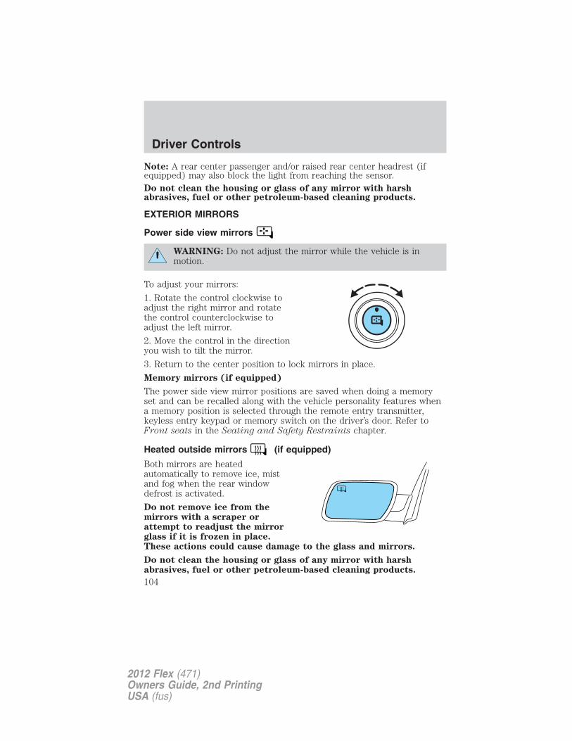
Note: A rear center passenger and/or raised rear center headrest (ifequipped) may also block the light from reaching the sensor.Do not clean the housing or glass of any mirror with harshabrasives, fuel or other petroleum-based cleaning products.
EXTERIOR MIRRORS
Power side view mirrors
WARNING: Do not adjust the mirror while the vehicle is inmotion.
To adjust your mirrors:
1. Rotate the control clockwise toadjust the right mirror and rotatethe control counterclockwise toadjust the left mirror.
2. Move the control in the directionyou wish to tilt the mirror.
3. Return to the center position to lock mirrors in place.
Memory mirrors (if equipped)
The power side view mirror positions are saved when doing a memoryset and can be recalled along with the vehicle personality features whena memory position is selected through the remote entry transmitter,keyless entry keypad or memory switch on the driver’s door. Refer toFront seats in the Seating and Safety Restraints chapter.
Heated outside mirrors (if equipped)
Both mirrors are heatedautomatically to remove ice, mistand fog when the rear windowdefrost is activated.
Do not remove ice from themirrors with a scraper orattempt to readjust the mirrorglass if it is frozen in place.These actions could cause damage to the glass and mirrors.
Do not clean the housing or glass of any mirror with harshabrasives, fuel or other petroleum-based cleaning products.
Driver Controls
104
2012 Flex (471)Owners Guide, 2nd PrintingUSA (fus)
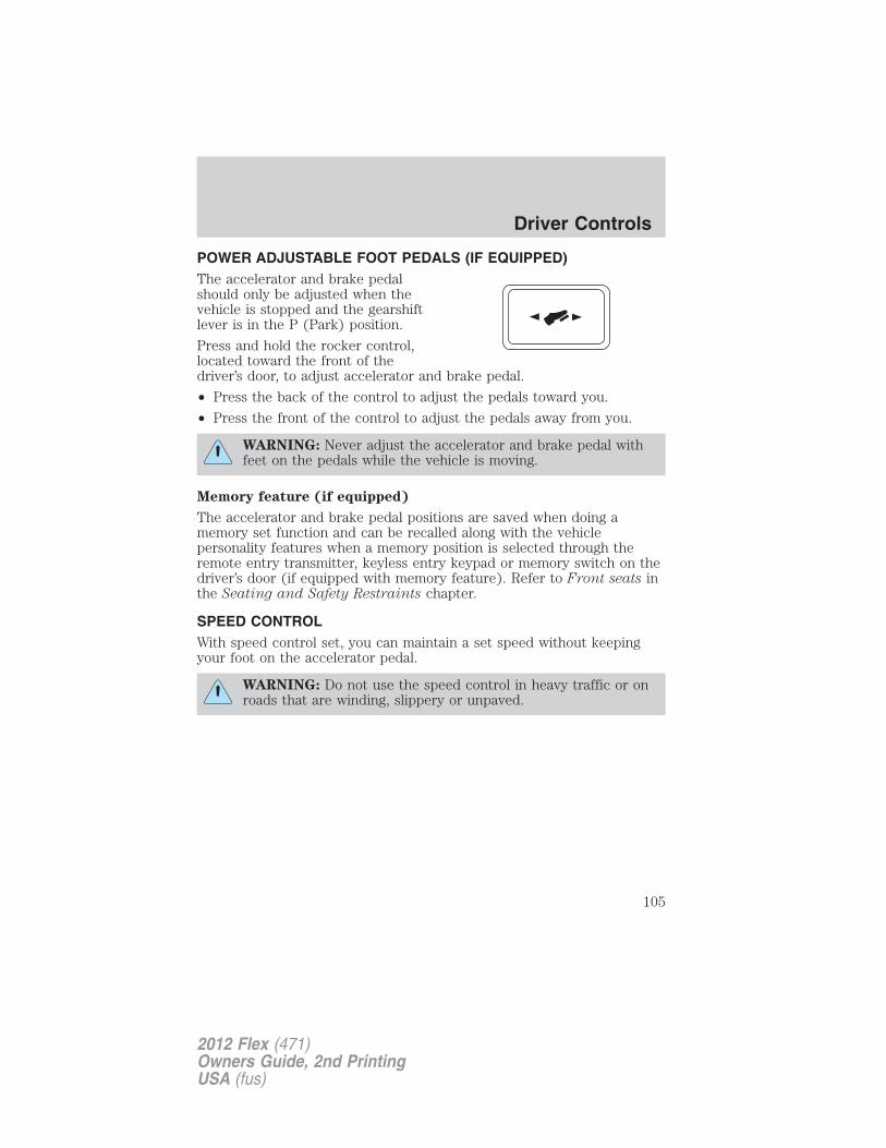
POWER ADJUSTABLE FOOT PEDALS (IF EQUIPPED)The accelerator and brake pedalshould only be adjusted when thevehicle is stopped and the gearshiftlever is in the P (Park) position.
Press and hold the rocker control,located toward the front of thedriver’s door, to adjust accelerator and brake pedal.
• Press the back of the control to adjust the pedals toward you.
• Press the front of the control to adjust the pedals away from you.
WARNING: Never adjust the accelerator and brake pedal withfeet on the pedals while the vehicle is moving.
Memory feature (if equipped)
The accelerator and brake pedal positions are saved when doing amemory set function and can be recalled along with the vehiclepersonality features when a memory position is selected through theremote entry transmitter, keyless entry keypad or memory switch on thedriver’s door (if equipped with memory feature). Refer to Front seats inthe Seating and Safety Restraints chapter.
SPEED CONTROLWith speed control set, you can maintain a set speed without keepingyour foot on the accelerator pedal.
WARNING: Do not use the speed control in heavy traffic or onroads that are winding, slippery or unpaved.
Driver Controls
105
2012 Flex (471)Owners Guide, 2nd PrintingUSA (fus)
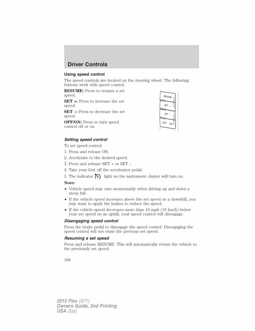
Using speed controlThe speed controls are located on the steering wheel. The followingbuttons work with speed control:
RESUME: Press to resume a setspeed.
SET +: Press to increase the setspeed.
SET –: Press to decrease the setspeed.
OFF/ON: Press to turn speedcontrol off or on.
Setting speed controlTo set speed control:
1. Press and release ON.
2. Accelerate to the desired speed.
3. Press and release SET + or SET -.
4. Take your foot off the accelerator pedal.
5. The indicator light on the instrument cluster will turn on.
Note:
• Vehicle speed may vary momentarily when driving up and down asteep hill.
• If the vehicle speed increases above the set speed on a downhill, youmay want to apply the brakes to reduce the speed.
• If the vehicle speed decreases more than 10 mph (16 km/h) belowyour set speed on an uphill, your speed control will disengage.
Disengaging speed controlPress the brake pedal to disengage the speed control. Disengaging thespeed control will not erase the previous set speed.
Resuming a set speedPress and release RESUME. This will automatically return the vehicle tothe previously set speed.
Driver Controls
106
2012 Flex (471)Owners Guide, 2nd PrintingUSA (fus)
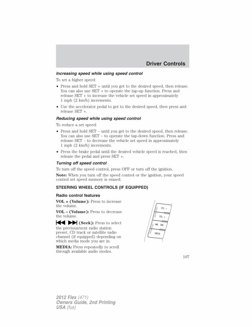
Increasing speed while using speed control
To set a higher speed:
• Press and hold SET + until you get to the desired speed, then release.You can also use SET + to operate the tap-up function. Press andrelease SET + to increase the vehicle set speed in approximately1 mph (2 km/h) increments.
• Use the accelerator pedal to get to the desired speed, then press andrelease SET +.
Reducing speed while using speed control
To reduce a set speed:
• Press and hold SET – until you get to the desired speed, then release.You can also use SET – to operate the tap-down function. Press andrelease SET – to decrease the vehicle set speed in approximately1 mph (2 km/h) increments.
• Press the brake pedal until the desired vehicle speed is reached, thenrelease the pedal and press SET +.
Turning off speed controlTo turn off the speed control, press OFF or turn off the ignition.
Note: When you turn off the speed control or the ignition, your speedcontrol set speed memory is erased.
STEERING WHEEL CONTROLS (IF EQUIPPED)
Radio control featuresVOL + (Volume): Press to increasethe volume.
VOL – (Volume): Press to decreasethe volume.
(Seek): Press to selectthe previous/next radio stationpreset, CD track or satellite radiochannel (if equipped) depending onwhich media mode you are in.
MEDIA: Press repeatedly to scrollthrough available audio modes.
Driver Controls
107
2012 Flex (471)Owners Guide, 2nd PrintingUSA (fus)
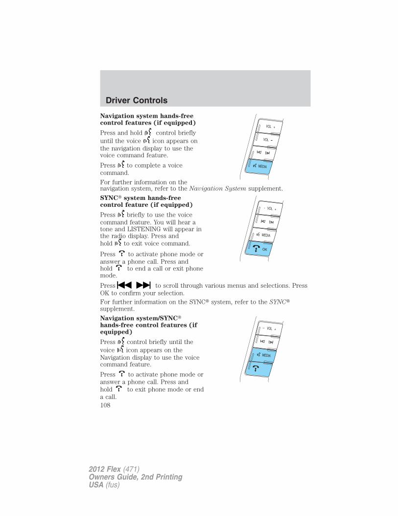
Navigation system hands-freecontrol features (if equipped)
Press and hold control brieflyuntil the voice icon appears onthe navigation display to use thevoice command feature.
Press to complete a voicecommand.
For further information on thenavigation system, refer to the Navigation System supplement.
SYNC� system hands-freecontrol feature (if equipped)
Press briefly to use the voicecommand feature. You will hear atone and LISTENING will appear inthe radio display. Press andhold to exit voice command.
Press to activate phone mode oranswer a phone call. Press andhold to end a call or exit phonemode.
Press to scroll through various menus and selections. PressOK to confirm your selection.For further information on the SYNC� system, refer to the SYNC�supplement.
Navigation system/SYNC�hands-free control features (ifequipped)
Press control briefly until thevoice icon appears on theNavigation display to use the voicecommand feature.
Press to activate phone mode oranswer a phone call. Press andhold to exit phone mode or enda call.
Driver Controls
108
2012 Flex (471)Owners Guide, 2nd PrintingUSA (fus)
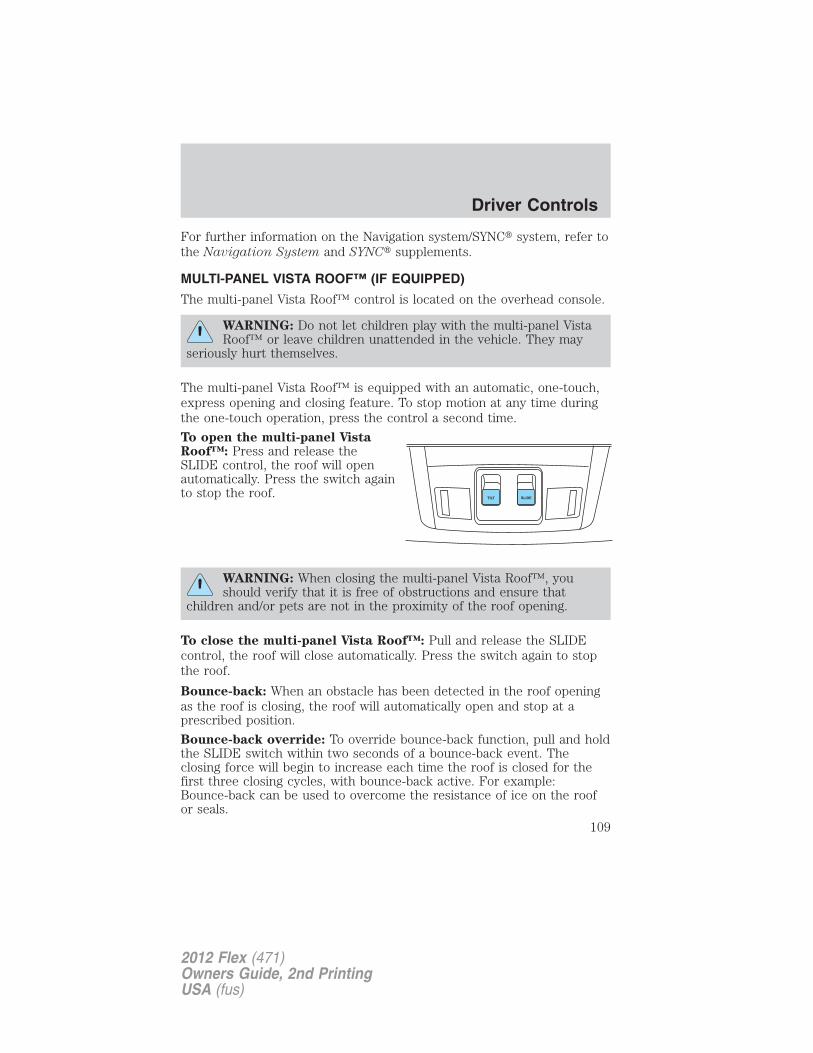
For further information on the Navigation system/SYNC� system, refer tothe Navigation System and SYNC� supplements.
MULTI-PANEL VISTA ROOF™ (IF EQUIPPED)
The multi-panel Vista Roof™ control is located on the overhead console.
WARNING: Do not let children play with the multi-panel VistaRoof™ or leave children unattended in the vehicle. They may
seriously hurt themselves.
The multi-panel Vista Roof™ is equipped with an automatic, one-touch,express opening and closing feature. To stop motion at any time duringthe one-touch operation, press the control a second time.
To open the multi-panel VistaRoof™: Press and release theSLIDE control, the roof will openautomatically. Press the switch againto stop the roof.
WARNING: When closing the multi-panel Vista Roof™, youshould verify that it is free of obstructions and ensure that
children and/or pets are not in the proximity of the roof opening.
To close the multi-panel Vista Roof™: Pull and release the SLIDEcontrol, the roof will close automatically. Press the switch again to stopthe roof.
Bounce-back: When an obstacle has been detected in the roof openingas the roof is closing, the roof will automatically open and stop at aprescribed position.
Bounce-back override: To override bounce-back function, pull and holdthe SLIDE switch within two seconds of a bounce-back event. Theclosing force will begin to increase each time the roof is closed for thefirst three closing cycles, with bounce-back active. For example:Bounce-back can be used to overcome the resistance of ice on the roofor seals.
Driver Controls
109
2012 Flex (471)Owners Guide, 2nd PrintingUSA (fus)
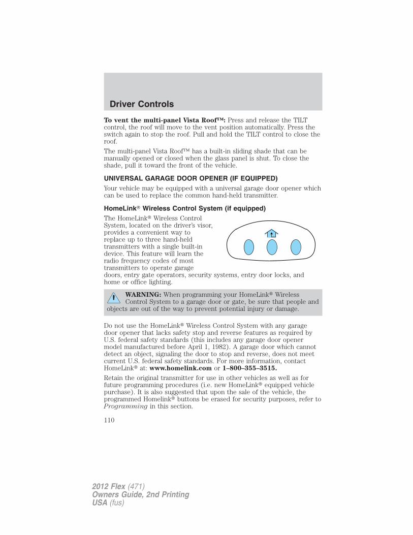
To vent the multi-panel Vista Roof™: Press and release the TILTcontrol, the roof will move to the vent position automatically. Press theswitch again to stop the roof. Pull and hold the TILT control to close theroof.
The multi-panel Vista Roof™ has a built-in sliding shade that can bemanually opened or closed when the glass panel is shut. To close theshade, pull it toward the front of the vehicle.
UNIVERSAL GARAGE DOOR OPENER (IF EQUIPPED)Your vehicle may be equipped with a universal garage door opener whichcan be used to replace the common hand-held transmitter.
HomeLink� Wireless Control System (if equipped)The HomeLink� Wireless ControlSystem, located on the driver’s visor,provides a convenient way toreplace up to three hand-heldtransmitters with a single built-indevice. This feature will learn theradio frequency codes of mosttransmitters to operate garagedoors, entry gate operators, security systems, entry door locks, andhome or office lighting.
WARNING: When programming your HomeLink� WirelessControl System to a garage door or gate, be sure that people and
objects are out of the way to prevent potential injury or damage.
Do not use the HomeLink� Wireless Control System with any garagedoor opener that lacks safety stop and reverse features as required byU.S. federal safety standards (this includes any garage door openermodel manufactured before April 1, 1982). A garage door which cannotdetect an object, signaling the door to stop and reverse, does not meetcurrent U.S. federal safety standards. For more information, contactHomeLink� at: www.homelink.com or 1–800–355–3515.
Retain the original transmitter for use in other vehicles as well as forfuture programming procedures (i.e. new HomeLink� equipped vehiclepurchase). It is also suggested that upon the sale of the vehicle, theprogrammed Homelink� buttons be erased for security purposes, refer toProgramming in this section.
Driver Controls
110
2012 Flex (471)Owners Guide, 2nd PrintingUSA (fus)
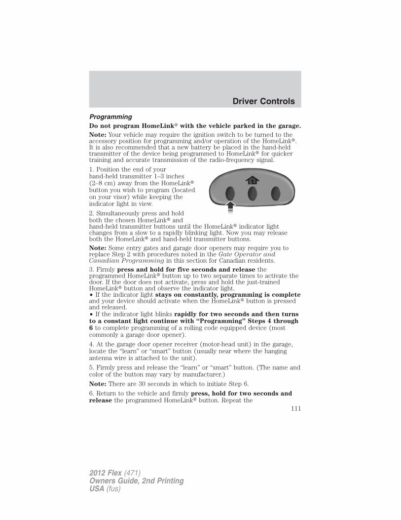
ProgrammingDo not program HomeLink� with the vehicle parked in the garage.
Note: Your vehicle may require the ignition switch to be turned to theaccessory position for programming and/or operation of the HomeLink�.It is also recommended that a new battery be placed in the hand-heldtransmitter of the device being programmed to HomeLink� for quickertraining and accurate transmission of the radio-frequency signal.
1. Position the end of yourhand-held transmitter 1–3 inches(2–8 cm) away from the HomeLink�button you wish to program (locatedon your visor) while keeping theindicator light in view.
2. Simultaneously press and holdboth the chosen HomeLink� andhand-held transmitter buttons until the HomeLink� indicator lightchanges from a slow to a rapidly blinking light. Now you may releaseboth the HomeLink� and hand-held transmitter buttons.Note: Some entry gates and garage door openers may require you toreplace Step 2 with procedures noted in the Gate Operator andCanadian Programming in this section for Canadian residents.3. Firmly press and hold for five seconds and release theprogrammed HomeLink� button up to two separate times to activate thedoor. If the door does not activate, press and hold the just-trainedHomeLink� button and observe the indicator light.• If the indicator light stays on constantly, programming is completeand your device should activate when the HomeLink� button is pressedand released.• If the indicator light blinks rapidly for two seconds and then turnsto a constant light continue with “Programming” Steps 4 through6 to complete programming of a rolling code equipped device (mostcommonly a garage door opener).
4. At the garage door opener receiver (motor-head unit) in the garage,locate the “learn” or “smart” button (usually near where the hangingantenna wire is attached to the unit).
5. Firmly press and release the “learn” or “smart” button. (The name andcolor of the button may vary by manufacturer.)
Note: There are 30 seconds in which to initiate Step 6.
6. Return to the vehicle and firmly press, hold for two seconds andrelease the programmed HomeLink� button. Repeat the
Driver Controls
111
2012 Flex (471)Owners Guide, 2nd PrintingUSA (fus)
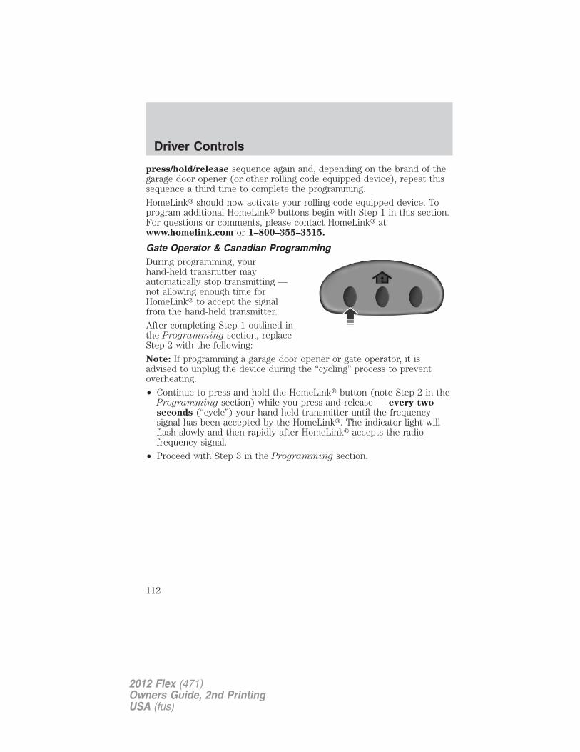
press/hold/release sequence again and, depending on the brand of thegarage door opener (or other rolling code equipped device), repeat thissequence a third time to complete the programming.
HomeLink� should now activate your rolling code equipped device. Toprogram additional HomeLink� buttons begin with Step 1 in this section.For questions or comments, please contact HomeLink� atwww.homelink.com or 1–800–355–3515.
Gate Operator & Canadian ProgrammingDuring programming, yourhand-held transmitter mayautomatically stop transmitting —not allowing enough time forHomeLink� to accept the signalfrom the hand-held transmitter.
After completing Step 1 outlined inthe Programming section, replaceStep 2 with the following:
Note: If programming a garage door opener or gate operator, it isadvised to unplug the device during the “cycling” process to preventoverheating.
• Continue to press and hold the HomeLink� button (note Step 2 in theProgramming section) while you press and release — every twoseconds (“cycle”) your hand-held transmitter until the frequencysignal has been accepted by the HomeLink�. The indicator light willflash slowly and then rapidly after HomeLink� accepts the radiofrequency signal.
• Proceed with Step 3 in the Programming section.
Driver Controls
112
2012 Flex (471)Owners Guide, 2nd PrintingUSA (fus)
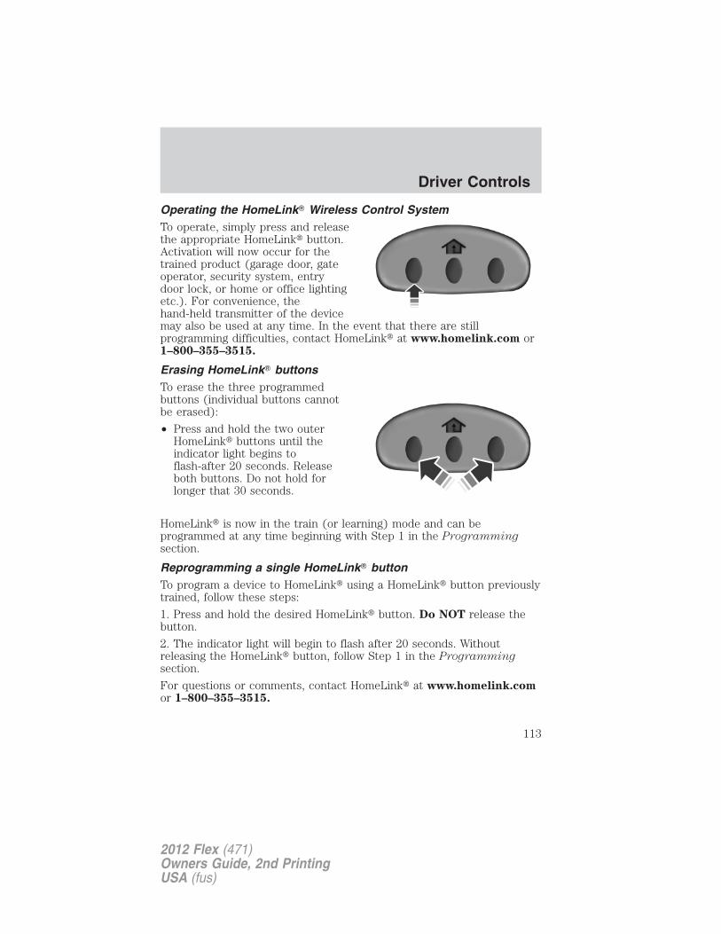
Operating the HomeLink� Wireless Control SystemTo operate, simply press and releasethe appropriate HomeLink� button.Activation will now occur for thetrained product (garage door, gateoperator, security system, entrydoor lock, or home or office lightingetc.). For convenience, thehand-held transmitter of the devicemay also be used at any time. In the event that there are stillprogramming difficulties, contact HomeLink� at www.homelink.com or1–800–355–3515.
Erasing HomeLink� buttonsTo erase the three programmedbuttons (individual buttons cannotbe erased):
• Press and hold the two outerHomeLink� buttons until theindicator light begins toflash-after 20 seconds. Releaseboth buttons. Do not hold forlonger that 30 seconds.
HomeLink� is now in the train (or learning) mode and can beprogrammed at any time beginning with Step 1 in the Programmingsection.
Reprogramming a single HomeLink� buttonTo program a device to HomeLink� using a HomeLink� button previouslytrained, follow these steps:
1. Press and hold the desired HomeLink� button. Do NOT release thebutton.
2. The indicator light will begin to flash after 20 seconds. Withoutreleasing the HomeLink� button, follow Step 1 in the Programmingsection.
For questions or comments, contact HomeLink� at www.homelink.comor 1–800–355–3515.
Driver Controls
113
2012 Flex (471)Owners Guide, 2nd PrintingUSA (fus)
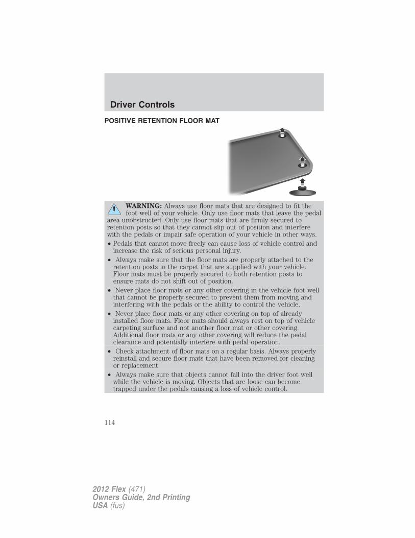
POSITIVE RETENTION FLOOR MAT
WARNING: Always use floor mats that are designed to fit thefoot well of your vehicle. Only use floor mats that leave the pedal
area unobstructed. Only use floor mats that are firmly secured toretention posts so that they cannot slip out of position and interferewith the pedals or impair safe operation of your vehicle in other ways.• Pedals that cannot move freely can cause loss of vehicle control and
increase the risk of serious personal injury.• Always make sure that the floor mats are properly attached to the
retention posts in the carpet that are supplied with your vehicle.Floor mats must be properly secured to both retention posts toensure mats do not shift out of position.
• Never place floor mats or any other covering in the vehicle foot wellthat cannot be properly secured to prevent them from moving andinterfering with the pedals or the ability to control the vehicle.
• Never place floor mats or any other covering on top of alreadyinstalled floor mats. Floor mats should always rest on top of vehiclecarpeting surface and not another floor mat or other covering.Additional floor mats or any other covering will reduce the pedalclearance and potentially interfere with pedal operation.
• Check attachment of floor mats on a regular basis. Always properlyreinstall and secure floor mats that have been removed for cleaningor replacement.
• Always make sure that objects cannot fall into the driver foot wellwhile the vehicle is moving. Objects that are loose can becometrapped under the pedals causing a loss of vehicle control.
Driver Controls
114
2012 Flex (471)Owners Guide, 2nd PrintingUSA (fus)
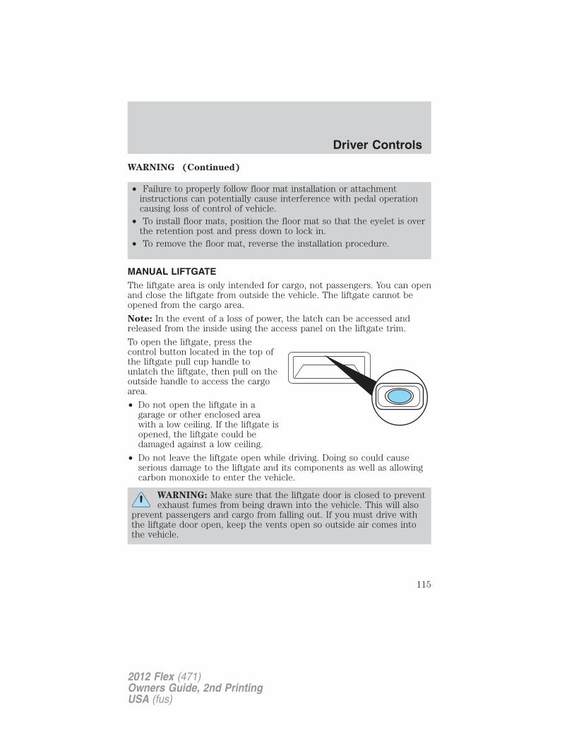
WARNING (Continued)
• Failure to properly follow floor mat installation or attachmentinstructions can potentially cause interference with pedal operationcausing loss of control of vehicle.
• To install floor mats, position the floor mat so that the eyelet is overthe retention post and press down to lock in.
• To remove the floor mat, reverse the installation procedure.
MANUAL LIFTGATEThe liftgate area is only intended for cargo, not passengers. You can openand close the liftgate from outside the vehicle. The liftgate cannot beopened from the cargo area.
Note: In the event of a loss of power, the latch can be accessed andreleased from the inside using the access panel on the liftgate trim.
To open the liftgate, press thecontrol button located in the top ofthe liftgate pull cup handle tounlatch the liftgate, then pull on theoutside handle to access the cargoarea.
• Do not open the liftgate in agarage or other enclosed areawith a low ceiling. If the liftgate isopened, the liftgate could bedamaged against a low ceiling.
• Do not leave the liftgate open while driving. Doing so could causeserious damage to the liftgate and its components as well as allowingcarbon monoxide to enter the vehicle.
WARNING: Make sure that the liftgate door is closed to preventexhaust fumes from being drawn into the vehicle. This will also
prevent passengers and cargo from falling out. If you must drive withthe liftgate door open, keep the vents open so outside air comes intothe vehicle.
Driver Controls
115
2012 Flex (471)Owners Guide, 2nd PrintingUSA (fus)
POWER LIFTGATE (IF EQUIPPED)You can power open or close the liftgate with the following controls:
• Instrument panel control button
• Integrated keyhead transmitter button
• Outside liftgate control button
• Control button in the rear cargo area
Note: The liftgate movement direction can be reversed with a secondpress of the instrument panel, or the rear cargo area control button, or asecond double press of the integrated keyhead transmitter button.
Opening and Closing the power liftgate:
WARNING: Make sure all persons are clear of the power liftgatearea before using the power liftgate control.
WARNING: Keep keys out of reach of children. Do not allowchildren to play near an open or moving power liftgate.
The liftgate will only operate with the vehicle in P (Park).
When the liftgate is being power closed, a chime will sound three timesas the liftgate begins to power close. A single chime indicates a problemwith the close request, caused by:
• the ignition is in on and the transmission is not in P (Park);
• or the battery voltage is below the minimum operating voltage;
• or the vehicle speed is at or above 3 mph (5 km/h).
If the liftgate reverses and starts to close after a open request, a fastcontinuous chime indicates excessive load on the gate or a possible strutfailure. If any excessive load is removed and you still have a fasterchime, have the system serviced immediately by your authorized dealer.
Do not attempt to manually force the liftgate to travel faster than thepower system will permit. This will activate the obstacle detectionfeature.
Note: Cycling the ignition prior to completely latching the liftgate couldresult in damage to the liftgate and/or its power components. Make surethe liftgate is fully latched before operating the vehicle.
Driver Controls
116
2012 Flex (471)Owners Guide, 2nd PrintingUSA (fus)
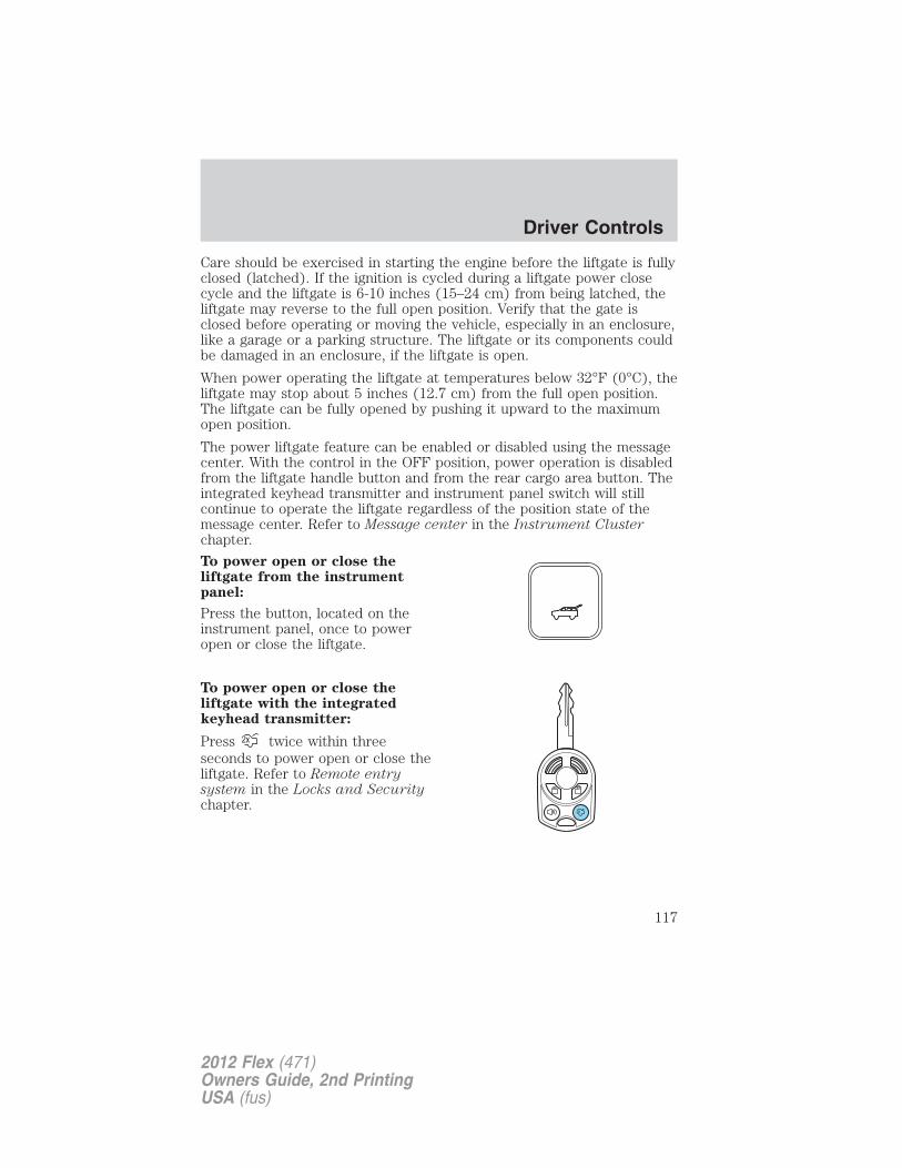
Care should be exercised in starting the engine before the liftgate is fullyclosed (latched). If the ignition is cycled during a liftgate power closecycle and the liftgate is 6-10 inches (15–24 cm) from being latched, theliftgate may reverse to the full open position. Verify that the gate isclosed before operating or moving the vehicle, especially in an enclosure,like a garage or a parking structure. The liftgate or its components couldbe damaged in an enclosure, if the liftgate is open.
When power operating the liftgate at temperatures below 32°F (0°C), theliftgate may stop about 5 inches (12.7 cm) from the full open position.The liftgate can be fully opened by pushing it upward to the maximumopen position.
The power liftgate feature can be enabled or disabled using the messagecenter. With the control in the OFF position, power operation is disabledfrom the liftgate handle button and from the rear cargo area button. Theintegrated keyhead transmitter and instrument panel switch will stillcontinue to operate the liftgate regardless of the position state of themessage center. Refer to Message center in the Instrument Clusterchapter.
To power open or close theliftgate from the instrumentpanel:
Press the button, located on theinstrument panel, once to poweropen or close the liftgate.
To power open or close theliftgate with the integratedkeyhead transmitter:
Press twice within threeseconds to power open or close theliftgate. Refer to Remote entrysystem in the Locks and Securitychapter.
Driver Controls
117
2012 Flex (471)Owners Guide, 2nd PrintingUSA (fus)
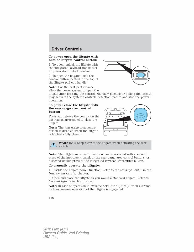
To power open the liftgate withoutside liftgate control button:
1. To open, unlock the liftgate withthe integrated keyhead transmitteror power door unlock control.
2. To open the liftgate, push thecontrol button located in the top ofthe liftgate pull cup handle.
Note: For the best performanceallow the power system to open theliftgate after pressing the control. Manually pushing or pulling the liftgatemay activate the system’s obstacle detection feature and stop the poweroperation.
To power close the liftgate withthe rear cargo area controlbutton:
Press and release the control on theleft rear quarter panel to close theliftgate.
Note: The rear cargo area controlbutton is disabled when the liftgateis latched (fully closed).
WARNING: Keep clear of the liftgate when activating the rearswitch.
Note: The liftgate movement direction can be reversed with a secondpress of the instrument panel, or the rear cargo area control buttons, ora second double press of the integrated keyhead transmitter button.
To manually operate the liftgate:
1. Disable the liftgate power function. Refer to the Message center in theInstrument Cluster chapter.
2. Open and close the liftgate as you would a standard liftgate. Refer toManual liftgate in this chapter.
Note: In case of operation in extreme cold -40°F (-40°C), or on extremeinclines, manual operation of the liftgate is suggested.
Driver Controls
118
2012 Flex (471)Owners Guide, 2nd PrintingUSA (fus)
Obstacle detection:
The power liftgate system is equipped with an obstacle detection feature.
If the power liftgate is closing, the system will reverse to full open whenit detects an obstacle. A chime will sound three times when an obstacleis detected as the liftgate begins to reopen. Once the obstacle isremoved, the liftgate can be closed under power.
If the power liftgate is opening, the system will stop and a chime willsound three times when an obstacle is detected. Once the obstacle isremoved, the liftgate can again be operated normally.
Resetting the power liftgate:
The power liftgate may not operate properly and may need to be reset ifany of these conditions occur:
• A low voltage or dead battery
• Disconnected battery
• The liftgate is manually closed and left ajar (unlatched)
To reset the power liftgate:
1. Disconnect the battery for 20 seconds then, reconnect the battery.
2. Manually close and fully latch the liftgate.
3. Power open the liftgate by using the integrated keyhead transmitter,or the instrument panel control button.
Note: If the power liftgate system is turned off in the message center,the system cannot be activated with the outside release handle or rearcargo area control button. The system will need to be turned on toresume operation with the outside release handle or rear cargo areacontrol button. The power liftgate is still operational through the use ofthe remote entry transmitter and instrument panel button when thepower liftgate is turned off in the message center.
Driver Controls
119
2012 Flex (471)Owners Guide, 2nd PrintingUSA (fus)
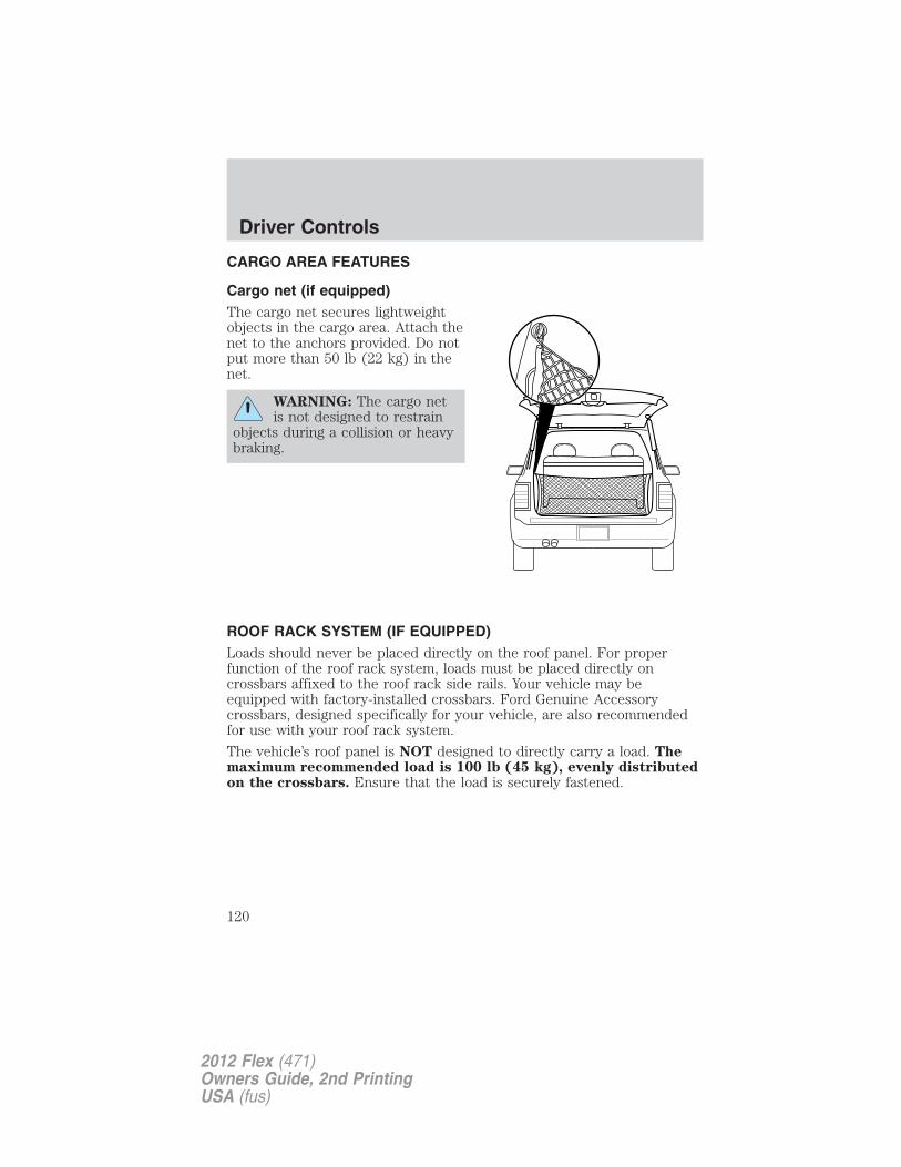
CARGO AREA FEATURES
Cargo net (if equipped)The cargo net secures lightweightobjects in the cargo area. Attach thenet to the anchors provided. Do notput more than 50 lb (22 kg) in thenet.
WARNING: The cargo netis not designed to restrain
objects during a collision or heavybraking.
ROOF RACK SYSTEM (IF EQUIPPED)Loads should never be placed directly on the roof panel. For properfunction of the roof rack system, loads must be placed directly oncrossbars affixed to the roof rack side rails. Your vehicle may beequipped with factory-installed crossbars. Ford Genuine Accessorycrossbars, designed specifically for your vehicle, are also recommendedfor use with your roof rack system.
The vehicle’s roof panel is NOT designed to directly carry a load. Themaximum recommended load is 100 lb (45 kg), evenly distributedon the crossbars. Ensure that the load is securely fastened.
Driver Controls
120
2012 Flex (471)Owners Guide, 2nd PrintingUSA (fus)
WARNING: When loading the roof rail crossbars, it isrecommended to evenly distribute the load, as well as maintain a
low center of gravity. Loaded vehicles, with higher centers of gravity,may handle differently than unloaded vehicles. Extra precautions, suchas slower speeds and increased stopping distance, should be takenwhen driving a heavily loaded vehicle.
When the rail system is loaded, check the tightness of the load beforedriving and at each fuel stop.
Driver Controls
121
2012 Flex (471)Owners Guide, 2nd PrintingUSA (fus)
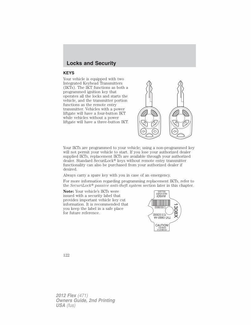
KEYSYour vehicle is equipped with twoIntegrated Keyhead Transmitters(IKTs). The IKT functions as both aprogrammed ignition key thatoperates all the locks and starts thevehicle, and the transmitter portionfunctions as the remote entrytransmitter. Vehicles with a powerliftgate will have a four-button IKTwhile vehicles without a powerliftgate will have a three-button IKT.
Your IKTs are programmed to your vehicle; using a non-programmed keywill not permit your vehicle to start. If you lose your authorized dealersupplied IKTs, replacement IKTs are available through your authorizeddealer. Standard SecuriLock� keys without remote entry transmitterfunctionality can also be purchased from your authorized dealer ifdesired.
Always carry a spare key with you in case of an emergency.
For more information regarding programming replacement IKTs, refer tothe SecuriLock� passive anti-theft system section later in this chapter.
Note: Your vehicle’s IKTs wereissued with a security label thatprovides important vehicle key cutinformation. It is recommended thatyou keep the label in a safe placefor future reference.
Locks and Security
122
2012 Flex (471)Owners Guide, 2nd PrintingUSA (fus)
MYKEY�
The MyKey� feature allows you to program a restricted driving mode topromote good driving habits. All but one of the keys programmed to thevehicle can be activated as a MyKey�. The key will remain restricteduntil MyKey� is cleared. Any remaining keys are referred to as an“administrator key” or admin key. The admin key can be used to create aMyKey�, program optional MyKey� settings, and clear the MyKey�feature. When the MyKey� feature is enabled the user can use systemcheck in the message center to see how many MyKeys� and admin keysare programmed to the vehicle, and how many total miles have beendriven with the MyKey� active.
MyKey� restricted features
Standard settings – These settings cannot be changed
• The audio system will be muted whenever Belt-Minder� is activateduntil the safety belts are buckled. Refer to the Seating and SafetyRestraints chapter for a detailed description of Belt-Minder�operation.
• Low fuel warnings are displayed in the message center followed by achime when the distance to empty value reaches 75 miles (120 km).
• The reverse sensing system cannot be turned off.
Optional settings – These settings can be changed
• Vehicle speed is limited to 80 mph (130 km/h). Visual warnings aredisplayed followed by a chime when the vehicle speed has reached80 mph (130 km/h).
• Visual warnings are displayed followed by a chime when a preselectedvehicle speed of 45, 55 or 65 mph (75, 90, or 105 km/h) is exceeded.
• The maximum volume of the audio system is limited to 45%. MYKEYVOLUME LIMITED will be displayed in the radio or (if equipped)navigation screen when attempting to exceed the limited volume.
• The AdvanceTrac� system cannot be turned off. When this optionalsetting is on, the MyKey� user will not be able to deactivate thesystem. Note: It may be beneficial to deactivate the AdvanceTrac�system if the vehicle is stuck in snow, mud, or sand.
Locks and Security
123
2012 Flex (471)Owners Guide, 2nd PrintingUSA (fus)
Create a MyKey�
To program MyKey� on one of the keys programmed to the vehicle,insert the key that you want to make a MyKey� into the ignition. Turnthe ignition on. Use the message center buttons to do the following:1. Press SETUP until PRESS RESET TO CREATE MYKEY is displayed.2. Press and release the RESET button. HOLD RESET TO CONFIRMMYKEY will be displayed.3. Press and hold the RESET button for two seconds until MARK THISAS RESTRICTED is displayed.4. Wait until KEY RESTRICTED AT NEXT START is displayed.MyKey� is successfully programmed. Make sure you label it so you candistinguish it from the admin keys. Note: To program the optionalsettings go to Step 2 in the Programming MyKey� optional settingssection. If your vehicle is equipped with remote start, see the UsingMyKey� with remote start systems section.Note: The MyKey� can be cleared within the same key cycle that it wascreated, otherwise a standard key (administrator key) is required toclear the MyKey� programming. To clear all MyKeys� go to Step 2 in theClear MyKey� section.Programming MyKey� optional settings
Turn the ignition on using an admin key. To program the optionalsettings, use the message center buttons to do the following:1. Press SETUP until RESET FOR MYKEY SETTINGS is displayed.2. Press and release the RESET button to display MyKey� setup menus.The first menu shown is:
MYKEY MAX MPH <80 MPH> OFF3. If you don’t want to change the maximum speed setting, press theSETUP button to display the next menu. The remaining menus appear asfollows with the default settings shown:
MYKEY MPH TONES 45 55 65 <OFF>MYKEY VOLUME LIMIT <ON> OFFMYKEY ADVTRAC CTRL ON <OFF>.
4. On any of the menus press RESET to highlight your choice with the<…>.
5. Press SETUP to enter your choice. The next optional setting will bedisplayed.
6. Repeat Steps 4 and 5 until you are done changing the optionalsettings.
Locks and Security
124
2012 Flex (471)Owners Guide, 2nd PrintingUSA (fus)
Clear MyKey�
To reset all MyKeys� as admin keys do the following:1. Turn the vehicle on using the admin key.2. Press SETUP until PRESS RESET TO CLEAR MYKEY is displayed.3. Press and release the RESET button. HOLD RESET TO CONFIRMCLEAR is displayed.4. Press and hold the RESET button for two seconds until ALL MYKEYSCLEARED is displayed.Check MyKey� system status
The vehicle system check will provide the status of the following MyKey�parameters:• MYKEY MILES — This odometer only tracks mileage when a MyKey�
is used. If mileage does not accumulate as expected, then the MyKey�is not being used by the intended user. The only way to reset thisodometer to zero is by clearing MyKey�. If this odometer is lower thanthe last time you checked, then the MyKey� system has been recentlycleared.
• # MYKEY(S) PROGRAMMED — Indicates how many MyKeys� areprogrammed to the vehicle. Can be used to detect deletion of aMyKey�.
• # ADMIN KEYS PROGRAMMED — Indicates how many admin keysare programmed to the vehicle. Can be used to detect if an additionalspare key has been programmed to the vehicle.
Refer to Message center in the Instrument Cluster chapter for MyKey�system warnings displays.
Using MyKey� with remote start systems
MyKey� is not compatible with non-Ford approved aftermarket remotestart systems. If you choose to install a remote start system please seeyour authorized dealer for a Ford approved remote start system.
When using a Ford-approved remote start system, the default settingswill recognize the remote start system as an additional admin key withits associated privileges. You should program the remote start system asa MyKey� in addition to the key that you have already programmed as aMyKey�. To program the remote start system as MyKey�, do thefollowing:
1. Enter the vehicle and close all doors.
2. Remote start the vehicle using a remote start fob.
Locks and Security
125
2012 Flex (471)Owners Guide, 2nd PrintingUSA (fus)
3. Follow Steps 1-4 in the Create a MyKey� section.
Note: For all vehicles, the number of MYKEY(S) PROGRAMMED orADMIN KEYS PROGRAMMED that is displayed in the MyKey� systemstatus menus will include the remote start system as an additional key inthe total count. See the Check MyKey� system status section.
Note: For all vehicles with remote start installed, it is possible toprogram all original vehicle keys as MyKeys�, in which case, you willneed to use your remote start system to reset all MyKeys� as admin keysby doing the following:
1. Enter the vehicle, close all doors.
2. Remote start the vehicle using your remote start fob.
3. Follow Steps 1-4 in the Clear MyKey� section.
Troubleshooting
Condition Potential Causes
Can’t create aMyKey�
• Key in the ignition is already a MyKey�• Key in the ignition is the last remaining adminkey (there always has to be at least one adminkey)• SecuriLock� passive anti-theft system isdisabled or in unlimited mode• Vehicle has been started using a remote startsystem that is programmed as MyKey�. Refer toUsing MyKey� with remote start systems
section.Cannot program theMyKey� optionalsettings
• Key in the ignition is a MyKey�• No MyKeys� are programmed to the vehicle.Refer to Create a MyKey� section• Vehicle has been started using a remote startsystem that is programmed as MyKey�. Refer toUsing MyKey� with remote start systems
section.
Locks and Security
126
2012 Flex (471)Owners Guide, 2nd PrintingUSA (fus)
Condition Potential Causes
Cannot clearMyKey�
• Key in the ignition is a MyKey�• No MyKeys� are programmed to the vehicle.Refer to Create a MyKey� section• Vehicle has been started using a remote startsystem that is programmed as MyKey�. Refer toUsing MyKey� with remote start systems
section.Lost the only adminkey
• Purchase a new key from your authorizeddealer
Lost any key • For programming spare keys, refer to theProgramming spare keys section in thischapter.
I accidentallyprogrammed all keysas MyKeys�
• Vehicle has a remote start system that isrecognized as an admin key. Refer to the Using
MyKey� with remote start systems section toreset all MyKeys� as admin keys.
MyKey�Programmed totalincludes oneadditional key
• Unknown key has been programmed to thevehicle as a MyKey�.• Vehicle is equipped with a remote startsystem. Refer to Using MyKey� with remote
start systems section.Admin KeysProgrammed totalincludes oneadditional key
• Unknown key has been programmed to thevehicle as admin key.• Vehicle is equipped with a remote startsystem. Refer to Using MyKey� with remote
start systems section.MyKey� miles do notaccumulate
• MyKey� is not being used by the intendeduser.• MyKey� system has been recently cleared.
Locks and Security
127
2012 Flex (471)Owners Guide, 2nd PrintingUSA (fus)
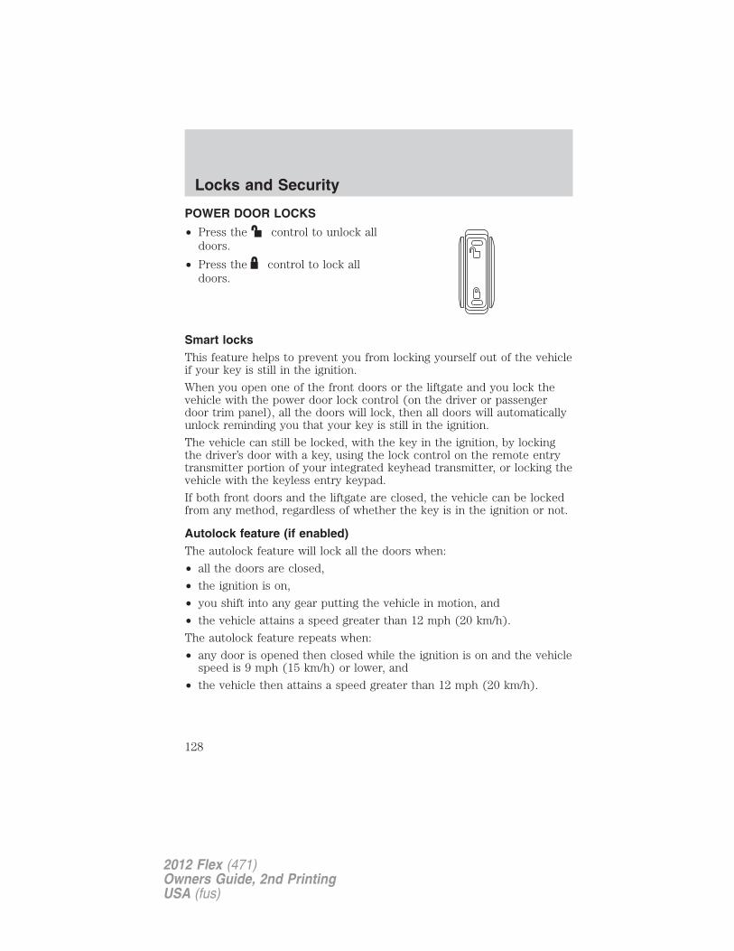
POWER DOOR LOCKS
• Press the control to unlock alldoors.
• Press the control to lock alldoors.
Smart locksThis feature helps to prevent you from locking yourself out of the vehicleif your key is still in the ignition.
When you open one of the front doors or the liftgate and you lock thevehicle with the power door lock control (on the driver or passengerdoor trim panel), all the doors will lock, then all doors will automaticallyunlock reminding you that your key is still in the ignition.
The vehicle can still be locked, with the key in the ignition, by lockingthe driver’s door with a key, using the lock control on the remote entrytransmitter portion of your integrated keyhead transmitter, or locking thevehicle with the keyless entry keypad.
If both front doors and the liftgate are closed, the vehicle can be lockedfrom any method, regardless of whether the key is in the ignition or not.
Autolock feature (if enabled)The autolock feature will lock all the doors when:
• all the doors are closed,
• the ignition is on,
• you shift into any gear putting the vehicle in motion, and
• the vehicle attains a speed greater than 12 mph (20 km/h).
The autolock feature repeats when:
• any door is opened then closed while the ignition is on and the vehiclespeed is 9 mph (15 km/h) or lower, and
• the vehicle then attains a speed greater than 12 mph (20 km/h).
Locks and Security
128
2012 Flex (471)Owners Guide, 2nd PrintingUSA (fus)
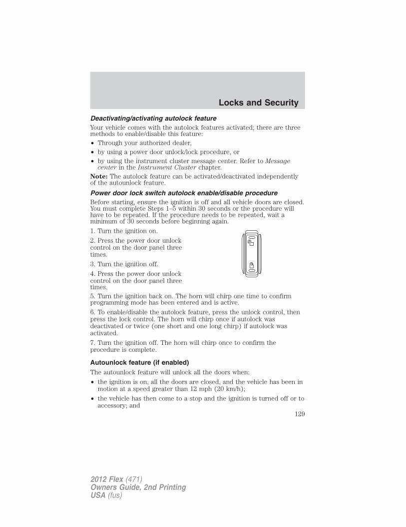
Deactivating/activating autolock featureYour vehicle comes with the autolock features activated; there are threemethods to enable/disable this feature:• Through your authorized dealer,• by using a power door unlock/lock procedure, or• by using the instrument cluster message center. Refer to Message
center in the Instrument Cluster chapter.Note: The autolock feature can be activated/deactivated independentlyof the autounlock feature.
Power door lock switch autolock enable/disable procedureBefore starting, ensure the ignition is off and all vehicle doors are closed.You must complete Steps 1–5 within 30 seconds or the procedure willhave to be repeated. If the procedure needs to be repeated, wait aminimum of 30 seconds before beginning again.
1. Turn the ignition on.
2. Press the power door unlockcontrol on the door panel threetimes.
3. Turn the ignition off.
4. Press the power door unlockcontrol on the door panel threetimes.5. Turn the ignition back on. The horn will chirp one time to confirmprogramming mode has been entered and is active.
6. To enable/disable the autolock feature, press the unlock control, thenpress the lock control. The horn will chirp once if autolock wasdeactivated or twice (one short and one long chirp) if autolock wasactivated.
7. Turn the ignition off. The horn will chirp once to confirm theprocedure is complete.
Autounlock feature (if enabled)The autounlock feature will unlock all the doors when:
• the ignition is on, all the doors are closed, and the vehicle has been inmotion at a speed greater than 12 mph (20 km/h);
• the vehicle has then come to a stop and the ignition is turned off or toaccessory; and
Locks and Security
129
2012 Flex (471)Owners Guide, 2nd PrintingUSA (fus)
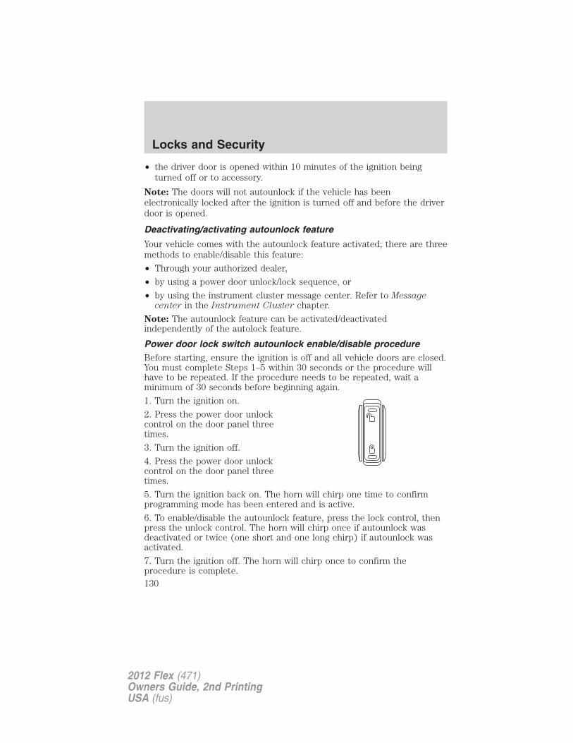
• the driver door is opened within 10 minutes of the ignition beingturned off or to accessory.
Note: The doors will not autounlock if the vehicle has beenelectronically locked after the ignition is turned off and before the driverdoor is opened.
Deactivating/activating autounlock feature
Your vehicle comes with the autounlock feature activated; there are threemethods to enable/disable this feature:
• Through your authorized dealer,
• by using a power door unlock/lock sequence, or
• by using the instrument cluster message center. Refer to Messagecenter in the Instrument Cluster chapter.
Note: The autounlock feature can be activated/deactivatedindependently of the autolock feature.
Power door lock switch autounlock enable/disable procedureBefore starting, ensure the ignition is off and all vehicle doors are closed.You must complete Steps 1–5 within 30 seconds or the procedure willhave to be repeated. If the procedure needs to be repeated, wait aminimum of 30 seconds before beginning again.
1. Turn the ignition on.
2. Press the power door unlockcontrol on the door panel threetimes.
3. Turn the ignition off.
4. Press the power door unlockcontrol on the door panel threetimes.
5. Turn the ignition back on. The horn will chirp one time to confirmprogramming mode has been entered and is active.
6. To enable/disable the autounlock feature, press the lock control, thenpress the unlock control. The horn will chirp once if autounlock wasdeactivated or twice (one short and one long chirp) if autounlock wasactivated.
7. Turn the ignition off. The horn will chirp once to confirm theprocedure is complete.
Locks and Security
130
2012 Flex (471)Owners Guide, 2nd PrintingUSA (fus)
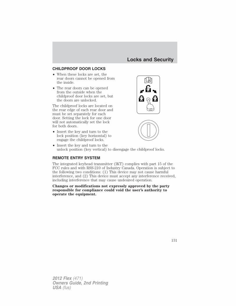
CHILDPROOF DOOR LOCKS• When these locks are set, the
rear doors cannot be opened fromthe inside.
• The rear doors can be openedfrom the outside when thechildproof door locks are set, butthe doors are unlocked.
The childproof locks are located onthe rear edge of each rear door andmust be set separately for eachdoor. Setting the lock for one doorwill not automatically set the lockfor both doors.
• Insert the key and turn to thelock position (key horizontal) toengage the childproof locks.
• Insert the key and turn to theunlock position (key vertical) to disengage the childproof locks.
REMOTE ENTRY SYSTEM
The integrated keyhead transmitter (IKT) complies with part 15 of theFCC rules and with RSS-210 of Industry Canada. Operation is subject tothe following two conditions: (1) This device may not cause harmfulinterference, and (2) This device must accept any interference received,including interference that may cause undesired operation.
Changes or modifications not expressly approved by the partyresponsible for compliance could void the user’s authority tooperate the equipment.
Locks and Security
131
2012 Flex (471)Owners Guide, 2nd PrintingUSA (fus)
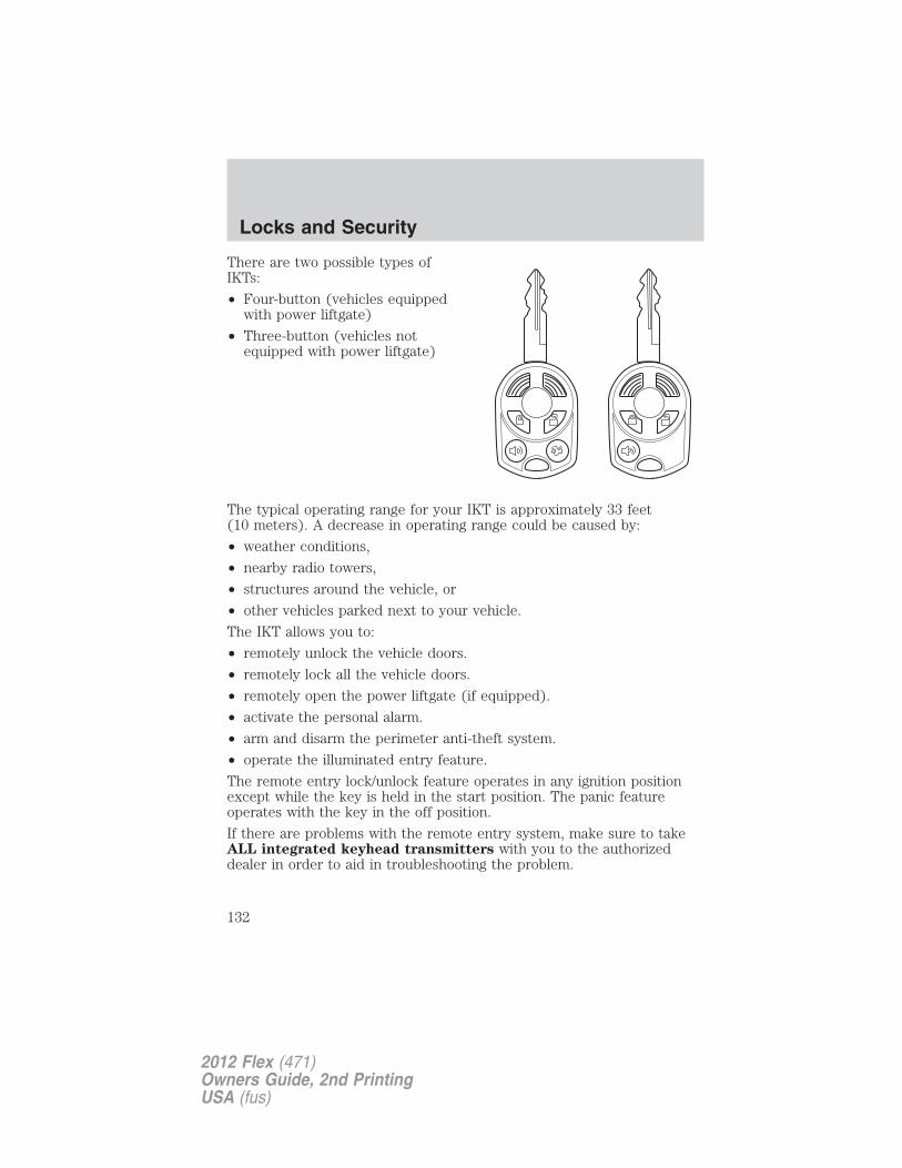
There are two possible types ofIKTs:
• Four-button (vehicles equippedwith power liftgate)
• Three-button (vehicles notequipped with power liftgate)
The typical operating range for your IKT is approximately 33 feet(10 meters). A decrease in operating range could be caused by:
• weather conditions,
• nearby radio towers,
• structures around the vehicle, or
• other vehicles parked next to your vehicle.
The IKT allows you to:
• remotely unlock the vehicle doors.
• remotely lock all the vehicle doors.
• remotely open the power liftgate (if equipped).
• activate the personal alarm.
• arm and disarm the perimeter anti-theft system.
• operate the illuminated entry feature.
The remote entry lock/unlock feature operates in any ignition positionexcept while the key is held in the start position. The panic featureoperates with the key in the off position.
If there are problems with the remote entry system, make sure to takeALL integrated keyhead transmitters with you to the authorizeddealer in order to aid in troubleshooting the problem.
Locks and Security
132
2012 Flex (471)Owners Guide, 2nd PrintingUSA (fus)
Unlocking the doors/two stage unlock
1. Press and release to unlock the driver’s door. Note: The interiorlamps and parking lamps will illuminate.
2. Press and release again within three seconds to unlock all thedoors.The remote entry system activates the illuminated entry feature; thisfeature turns on the lamps for 25 seconds or until the ignition is turnedto the on position.
The battery saver feature will turn off the lamps 10 minutes after theignition is turned to the off position.
Two stage unlocking may be disabled or re-enabled by simultaneouslypressing the and controls on the IKT for four seconds (disablingtwo stage unlock allows all vehicle doors to unlock simultaneously). Theparking lamps will flash twice to indicate that two-stage unlock wasenabled or disabled.
Locking the doors
1. Press and release to lock all the doors. The parking lamps willilluminate.
2. Press and release again within three seconds to confirm that allthe doors are closed. Note: The doors will lock again, the horn will chirpand the turn lamps will illuminate if all the doors and liftgate are closed.
Note: If any door or the liftgate is not closed, the horn will chirp twiceand the lamps will not flash.
Car finder
Press twice within three seconds. The horn will chirp and the turnlamps will flash. It is recommended that this method be used to locateyour vehicle, rather than using the panic alarm.
Sounding a panic alarm
Press to activate the alarm. The horn will sound and the turn lampswill flash for a maximum of three minutes. Press again or turn theignition to the on position to deactivate, or wait for the alarm to time outin three minutes.
Note: The panic alarm will only operate when the ignition is in the offposition.
Locks and Security
133
2012 Flex (471)Owners Guide, 2nd PrintingUSA (fus)
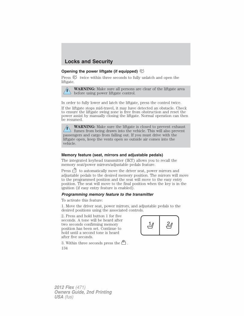
Opening the power liftgate (if equipped)
Press twice within three seconds to fully unlatch and open theliftgate.
WARNING: Make sure all persons are clear of the liftgate areabefore using power liftgate control.
In order to fully lower and latch the liftgate, press the control twice.If the liftgate stops mid-travel, it may have detected an obstacle. Checkto ensure the liftgate swing zone is free from obstruction and reset thepower assist by manually closing the liftgate. Normal operation can thenbe resumed.
WARNING: Make sure the liftgate is closed to prevent exhaustfumes from being drawn into the vehicle. This will also prevent
passengers and cargo from falling out. If you must drive with theliftgate open, keep the vents open so outside air comes into thevehicle.
Memory feature (seat, mirrors and adjustable pedals)The integrated keyhead transmitter (IKT) allows you to recall thememory seat/power mirrors/adjustable pedals feature.
Press to automatically move the driver seat, power mirrors andadjustable pedals to the desired memory position. The mirrors will moveto the programmed position and the seat will move to the easy entryposition. The seat will move to the final position when the key is in theignition (if easy entry feature is enabled).
Programming memory feature to the transmitterTo activate this feature:
1. Move the driver seat, power mirrors, and adjustable pedals to thedesired positions using the associated controls.
2. Press and hold button 1 for fiveseconds. A tone will be heard aftertwo seconds confirming memoryposition has been set. Continue tohold until a second tone is heardafter five seconds.
3. Within three seconds press the .
Locks and Security
134
2012 Flex (471)Owners Guide, 2nd PrintingUSA (fus)
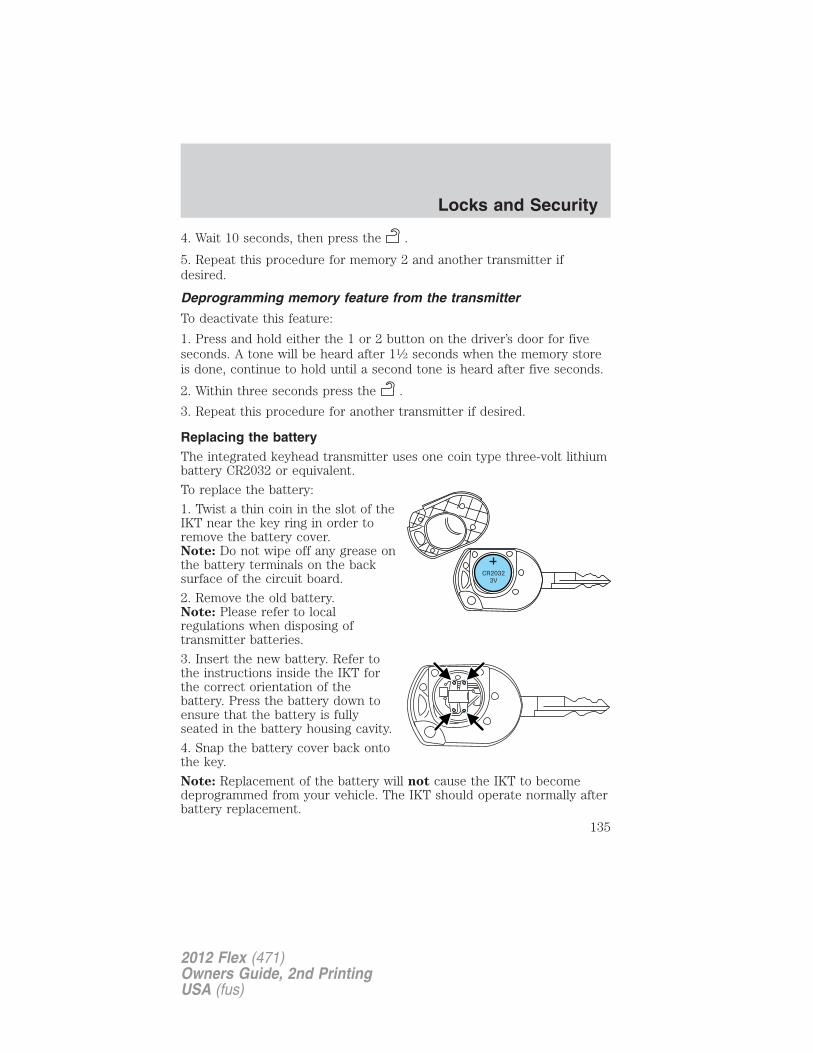
4. Wait 10 seconds, then press the .
5. Repeat this procedure for memory 2 and another transmitter ifdesired.
Deprogramming memory feature from the transmitter
To deactivate this feature:
1. Press and hold either the 1 or 2 button on the driver’s door for fiveseconds. A tone will be heard after 11⁄2 seconds when the memory storeis done, continue to hold until a second tone is heard after five seconds.
2. Within three seconds press the .
3. Repeat this procedure for another transmitter if desired.
Replacing the batteryThe integrated keyhead transmitter uses one coin type three-volt lithiumbattery CR2032 or equivalent.
To replace the battery:
1. Twist a thin coin in the slot of theIKT near the key ring in order toremove the battery cover.Note: Do not wipe off any grease onthe battery terminals on the backsurface of the circuit board.
2. Remove the old battery.Note: Please refer to localregulations when disposing oftransmitter batteries.
3. Insert the new battery. Refer tothe instructions inside the IKT forthe correct orientation of thebattery. Press the battery down toensure that the battery is fullyseated in the battery housing cavity.
4. Snap the battery cover back ontothe key.
Note: Replacement of the battery will not cause the IKT to becomedeprogrammed from your vehicle. The IKT should operate normally afterbattery replacement.
Locks and Security
135
2012 Flex (471)Owners Guide, 2nd PrintingUSA (fus)
Replacing lost integrated keyhead transmitters (IKTs)If you would like to have your integrated keyhead transmittersreprogrammed because you lost one, or would like to buy additionalIKTs, you can either reprogram them yourself, or take all IKTs to yourauthorized dealer for reprogramming.
How to reprogram your integrated keyhead transmitters (IKTs)To program a new integrated keyhead transmitter yourself, refer toProgramming spare keys in the SecuriLock� passive anti-theft systemsection of this chapter. Note: At least two IKTs are required to performthis procedure yourself.
Illuminated entryThe interior lamps and puddle lamps (if equipped) illuminate when theintegrated keyhead transmitter or the keyless entry system keypad isused to unlock the door(s).The illuminated entry system will turn off the interior lights if:• the ignition is turned to the on position, or
• the integrated keyhead transmitter control is pressed, or
• the vehicle is locked using the keyless entry keypad, or• after 25 seconds of illumination.The inside lights will not turn off if:• they have been turned on with the dimmer control, or• any door is open.
Illuminated exit• When all vehicle doors are closed and the key is removed from the
ignition, the interior dome lamps, parking lamps and the exteriormirror puddle lamps (if equipped) will illuminate.
The lights will turn off if all the doors remain closed and• 25 seconds elapse, or• the key is inserted in the ignition.
Battery saverThe battery saver will shut off the interior lamps 10 minutes after theignition has been turned to the off position.
• If the dome lamps were turned on using the panel dimmer control, thebattery saver will shut them off 10 minutes after the ignition has beenturned to the off position.
Locks and Security
136
2012 Flex (471)Owners Guide, 2nd PrintingUSA (fus)
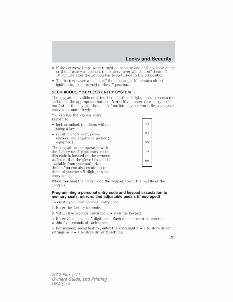
• If the courtesy lamps were turned on because one of the vehicle doorsor the liftgate was opened, the battery saver will shut off them off10 minutes after the ignition has been turned to the off position.
• The battery saver will shut off the headlamps 10 minutes after theignition has been turned to the off position.
SECURICODE™ KEYLESS ENTRY SYSTEMThe keypad is invisible until touched and then it lights up so you can seeand touch the appropriate buttons. Note: If you enter your entry codetoo fast on the keypad, the unlock function may not work. Re-enter yourentry code more slowly.
You can use the keyless entrykeypad to:
• lock or unlock the doors withoutusing a key.
• recall memory seat, powermirrors, and adjustable pedals (ifequipped).
The keypad can be operated withthe factory set 5–digit entry code;this code is located on the owner’swallet card in the glove box and isavailable from your authorizeddealer. You can also create up tothree of your own 5–digit personalentry codes.
When touching the controls on the keypad, touch the middle of thecontrols.
Programming a personal entry code and keypad association tomemory seats, mirrors, and adjustable pedals (if equipped)To create your own personal entry code:
1. Enter the factory set code.
2. Within five seconds touch the 1 • 2 on the keypad.
3. Enter your personal 5-digit code. Each number must be enteredwithin five seconds of each other.
4. For memory recall feature, enter the sixth digit 1 • 2 to store driver 1settings or 3 • 4 to store driver 2 settings.
Locks and Security
137
2012 Flex (471)Owners Guide, 2nd PrintingUSA (fus)
Note: Touching 5 • 6, 7 • 8, or 9 • 0 keypad numbers as a sixth digitwill not recall a driver memory setting.Note: The factory-set code cannot be associated with a memory setting.5. The doors will lock then unlock to confirm that your personal entrycode has been programmed to the module.Tips:
• Do not set a code that uses five of the same number.• Do not use five numbers in sequential order.• The factory set code will work even if you have set your own personal
code.
Erasing personal code1. Enter the factory set 5–digit code.2. Within five seconds, touch the 1 • 2 on the keypad and release.3. Touch and hold the 1 • 2 for two seconds. This must be done withinfive seconds of completing Step 2.All personal codes are now erased and only the factory set 5–digit codewill work.
Anti-scan featureIf the wrong code has been entered seven times (35 consecutive numbertouches), the keypad will go into an anti-scan mode. This mode disablesthe keypad for one minute and the keypad lamp will flash.
The anti-scan feature will turn off after:
• one minute of keypad inactivity.
• pressing the control on the remote entry transmitter portion ofyour integrated keyhead transmitter.
• the ignition is turned on.
Unlocking and locking the doors using keyless entryTo unlock the driver’s door, enter the factory set 5-digit code or yourpersonal code. Each number must be touched within five seconds ofeach other. The interior lamps will illuminate. Note: If the two-stageunlocking feature is disabled, all doors will unlock; for more informationregarding two-stage unlocking, refer to the Unlocking the doors/Twostage unlock section earlier in this chapter.
To unlock all doors, enter the factory set code or your personal code,then touch the 3 • 4 control within five seconds.
Locks and Security
138
2012 Flex (471)Owners Guide, 2nd PrintingUSA (fus)
To lock all doors, press and hold the 7 • 8 and the 9 • 0 at the sametime (with the driver’s door closed) for one second. You do not need toenter the keypad code first.
SECURILOCK� PASSIVE ANTI-THEFT SYSTEM
SecuriLock� passive anti-theft system is an engine immobilizationsystem. This system is designed to help prevent the engine from beingstarted unless a coded integrated keyhead transmitter (IKT)programmed to your vehicle is used. The use of the wrong type ofcoded key may lead to a “no-start” condition.
Your vehicle comes with two coded integrated keyhead transmitters;additional coded IKTs may be purchased from your authorized dealer.Standard SecuriLock� keys without remote entry transmitterfunctionality can also be purchased from your authorized dealer ifdesired. The authorized dealer can program your spare IKTs to yourvehicle or you can program the IKTs yourself. Refer to Programmingspare keys for instructions on how to program the coded key.
Note: The SecuriLock� passive anti-theft system is not compatible withnon-Ford aftermarket remote start systems. Use of these systems mayresult in vehicle starting problems and a loss of security protection.
Note: Large metallic objects, electronic devices that are used topurchase gasoline or similar items, or a second coded key on the samekey chain may cause vehicle starting issues. You need to prevent theseobjects from touching the coded IKT while starting the engine. Theseobjects will not cause damage to the coded IKT, but may cause amomentary issue if they are too close to the IKT when starting theengine. If a problem occurs, turn the ignition off, remove all objects onthe key chain away from the coded IKT and restart the engine.
Note: Do not leave a duplicate coded key in the vehicle. Alwaystake your keys and lock all doors when leaving the vehicle.
Locks and Security
139
2012 Flex (471)Owners Guide, 2nd PrintingUSA (fus)
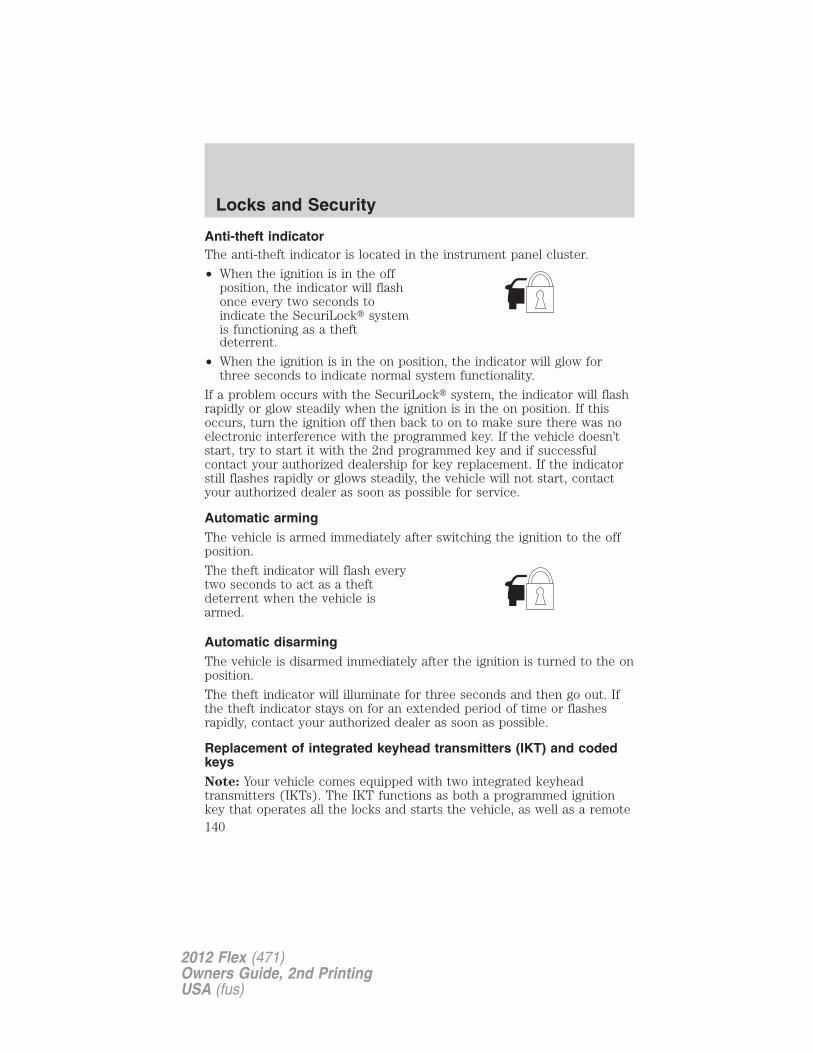
Anti-theft indicatorThe anti-theft indicator is located in the instrument panel cluster.
• When the ignition is in the offposition, the indicator will flashonce every two seconds toindicate the SecuriLock� systemis functioning as a theftdeterrent.
• When the ignition is in the on position, the indicator will glow forthree seconds to indicate normal system functionality.
If a problem occurs with the SecuriLock� system, the indicator will flashrapidly or glow steadily when the ignition is in the on position. If thisoccurs, turn the ignition off then back to on to make sure there was noelectronic interference with the programmed key. If the vehicle doesn’tstart, try to start it with the 2nd programmed key and if successfulcontact your authorized dealership for key replacement. If the indicatorstill flashes rapidly or glows steadily, the vehicle will not start, contactyour authorized dealer as soon as possible for service.
Automatic armingThe vehicle is armed immediately after switching the ignition to the offposition.
The theft indicator will flash everytwo seconds to act as a theftdeterrent when the vehicle isarmed.
Automatic disarmingThe vehicle is disarmed immediately after the ignition is turned to the onposition.
The theft indicator will illuminate for three seconds and then go out. Ifthe theft indicator stays on for an extended period of time or flashesrapidly, contact your authorized dealer as soon as possible.
Replacement of integrated keyhead transmitters (IKT) and codedkeysNote: Your vehicle comes equipped with two integrated keyheadtransmitters (IKTs). The IKT functions as both a programmed ignitionkey that operates all the locks and starts the vehicle, as well as a remote
Locks and Security
140
2012 Flex (471)Owners Guide, 2nd PrintingUSA (fus)
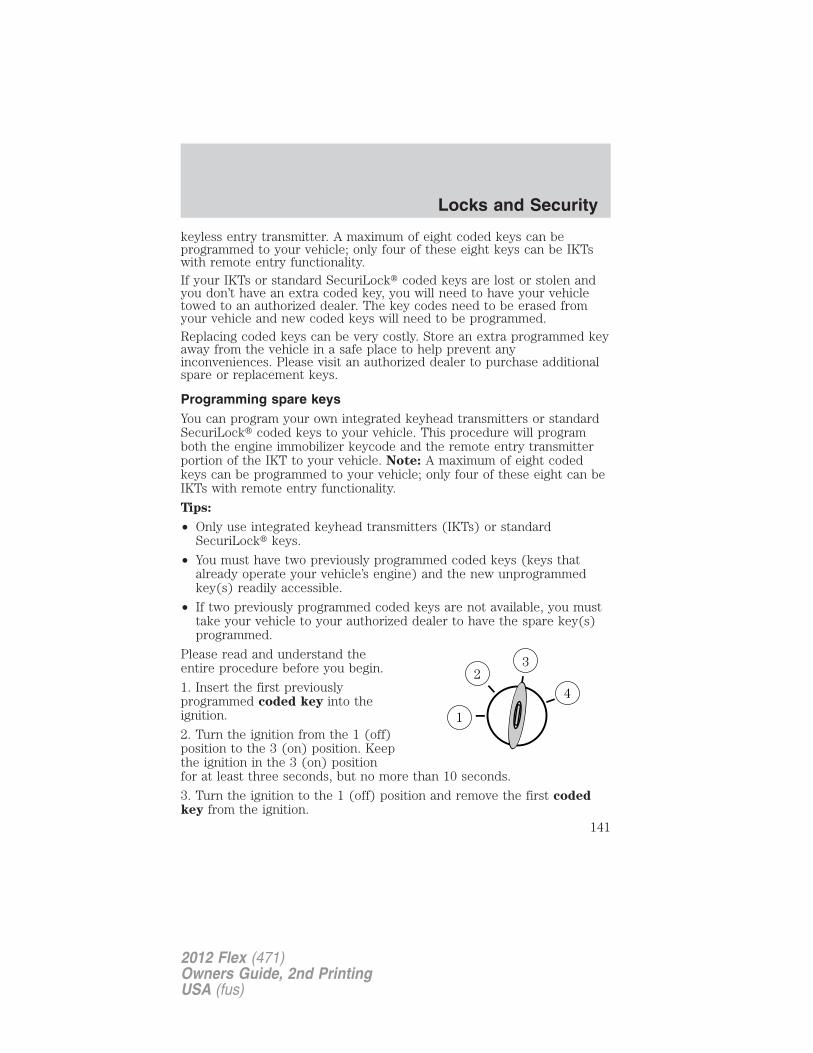
keyless entry transmitter. A maximum of eight coded keys can beprogrammed to your vehicle; only four of these eight keys can be IKTswith remote entry functionality.If your IKTs or standard SecuriLock� coded keys are lost or stolen andyou don’t have an extra coded key, you will need to have your vehicletowed to an authorized dealer. The key codes need to be erased fromyour vehicle and new coded keys will need to be programmed.Replacing coded keys can be very costly. Store an extra programmed keyaway from the vehicle in a safe place to help prevent anyinconveniences. Please visit an authorized dealer to purchase additionalspare or replacement keys.
Programming spare keysYou can program your own integrated keyhead transmitters or standardSecuriLock� coded keys to your vehicle. This procedure will programboth the engine immobilizer keycode and the remote entry transmitterportion of the IKT to your vehicle. Note: A maximum of eight codedkeys can be programmed to your vehicle; only four of these eight can beIKTs with remote entry functionality.
Tips:
• Only use integrated keyhead transmitters (IKTs) or standardSecuriLock� keys.
• You must have two previously programmed coded keys (keys thatalready operate your vehicle’s engine) and the new unprogrammedkey(s) readily accessible.
• If two previously programmed coded keys are not available, you musttake your vehicle to your authorized dealer to have the spare key(s)programmed.
Please read and understand theentire procedure before you begin.
1. Insert the first previouslyprogrammed coded key into theignition.
2. Turn the ignition from the 1 (off)position to the 3 (on) position. Keepthe ignition in the 3 (on) positionfor at least three seconds, but no more than 10 seconds.
3. Turn the ignition to the 1 (off) position and remove the first codedkey from the ignition.
Locks and Security
141
2012 Flex (471)Owners Guide, 2nd PrintingUSA (fus)
4. After three seconds but within 10 seconds of turning the ignition tothe 1 (off) position, insert the second previously coded key into theignition.5. Turn the ignition from the 1 (off) position to the 3 (on) position. Keepthe ignition in the 3 (on) position for at least three seconds, but no morethan 10 seconds.6. Turn the ignition to the 1 (off) position and remove the secondpreviously programmed coded key from the ignition.7. After three seconds but within 20 seconds of turning the ignition tothe 1 (off) position and removing the previously programmed codedkey, insert the new unprogrammed key (new key/valet key) into theignition.8. Turn the ignition from the 1 (off) position to the 3 (on) position. Keepthe ignition in the 3 (on) position for at least six seconds.
9. Remove the newly programmed coded key from the ignition.
If the key has been successfully programmed it will start the vehicle’sengine and will operate the remote entry system (if the new key is anintegrated keyhead transmitter). The theft indicator light will illuminatefor three seconds and then go out to indicate successful programming.
If the key was not successfully programmed, it will not start yourvehicle’s engine and/or will not operate the remote entry features. Thetheft indicator light may flash on and off. Wait 20 seconds and you mayrepeat Steps 1 through 8. If failure repeats, bring your vehicle to yourauthorized dealer to have the new key(s) programmed.
To program additional new unprogrammed key(s), wait 20 seconds andthen repeat this procedure from Step 1.
Note: To program MyKey� features, refer to MyKey� in this chapter.
PERIMETER ALARM SYSTEM (IF EQUIPPED)The perimeter alarm system will warn you of unauthorized entry of yourvehicle.
The armed system will be triggered if:
• any door, the hood or the liftgate is opened without using the keypador the remote entry transmitter portion of your IKT.
• the ignition is turned on with an invalid SecuriLock� key or IKT.
If there is any potential perimeter anti-theft problem with your vehicle,ensure ALL integrated keyhead transmitters are brought to anauthorized dealer to aid in troubleshooting.
Locks and Security
142
2012 Flex (471)Owners Guide, 2nd PrintingUSA (fus)
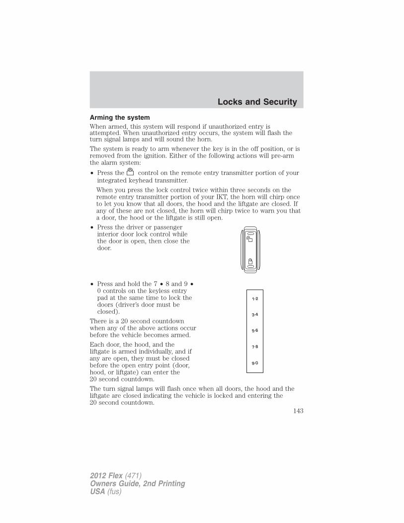
Arming the systemWhen armed, this system will respond if unauthorized entry isattempted. When unauthorized entry occurs, the system will flash theturn signal lamps and will sound the horn.
The system is ready to arm whenever the key is in the off position, or isremoved from the ignition. Either of the following actions will pre-armthe alarm system:
• Press the control on the remote entry transmitter portion of yourintegrated keyhead transmitter.
When you press the lock control twice within three seconds on theremote entry transmitter portion of your IKT, the horn will chirp onceto let you know that all doors, the hood and the liftgate are closed. Ifany of these are not closed, the horn will chirp twice to warn you thata door, the hood or the liftgate is still open.
• Press the driver or passengerinterior door lock control whilethe door is open, then close thedoor.
• Press and hold the 7 • 8 and 9 •0 controls on the keyless entrypad at the same time to lock thedoors (driver’s door must beclosed).
There is a 20 second countdownwhen any of the above actions occurbefore the vehicle becomes armed.
Each door, the hood, and theliftgate is armed individually, and ifany are open, they must be closedbefore the open entry point (door,hood, or liftgate) can enter the20 second countdown.
The turn signal lamps will flash once when all doors, the hood and theliftgate are closed indicating the vehicle is locked and entering the20 second countdown.
Locks and Security
143
2012 Flex (471)Owners Guide, 2nd PrintingUSA (fus)
Disarming the systemYou can disarm the system by any of the following actions:
• Unlock the doors by using the remote entry transmitter portion ofyour integrated keyhead transmitter (IKT).
• Unlock the doors by using your keyless entry pad.
• Turn ignition on with a valid SecuriLock� key or IKT.
• Press the panic control on the remote entry transmitter portion ofyour IKT. This will only shut off the horn and turn lamps when thealarm is sounding. The alarm system will still be armed.
Pressing the power door unlock control within the initial 20-secondprearmed mode will return the vehicle to a disarmed state.
Note: If the driver’s door is unlocked with a key, a chime will soundwhen you open the door and the message center will display TO STOPALARM START VEHICLE. When this occurs, you will have 12 seconds todisarm the alarm using any of the actions above, otherwise the alarm willtrigger.
Locks and Security
144
2012 Flex (471)Owners Guide, 2nd PrintingUSA (fus)
FRONT SEATS
WARNING: Reclining the seatback can cause an occupant toslide under the seat’s safety belt, resulting in severe personal
injuries in the event of a collision.
WARNING: Do not pile cargo higher than the seatbacks toreduce the risk of injury in a collision or sudden stop.
WARNING: Before returning the seatback to its originalposition, make sure that cargo or any objects are not trapped
behind the seatback. After returning the seatback to its originalposition, pull on the seatback to ensure that it has fully latched. Anunlatched seat may become dangerous in the event of a sudden stop orcollision.
WARNING: Never adjust the driver’s seat or seatback when thevehicle is moving.
WARNING: Always drive and ride with your seatback uprightand the lap belt snug and low across the hips.
Adjustable head restraints
Your vehicle is equipped with front row outboard head restraints that arevertically adjustable.
WARNING: To minimize the risk of neck injury in the event of acrash, the driver and passenger occupants should not sit in
and/or operate the vehicle, until the head restraint is placed in itsproper position. The driver should never adjust the head restraintwhile the vehicle is in motion.
Seating and Safety Restraints
145
2012 Flex (471)Owners Guide, 2nd PrintingUSA (fus)
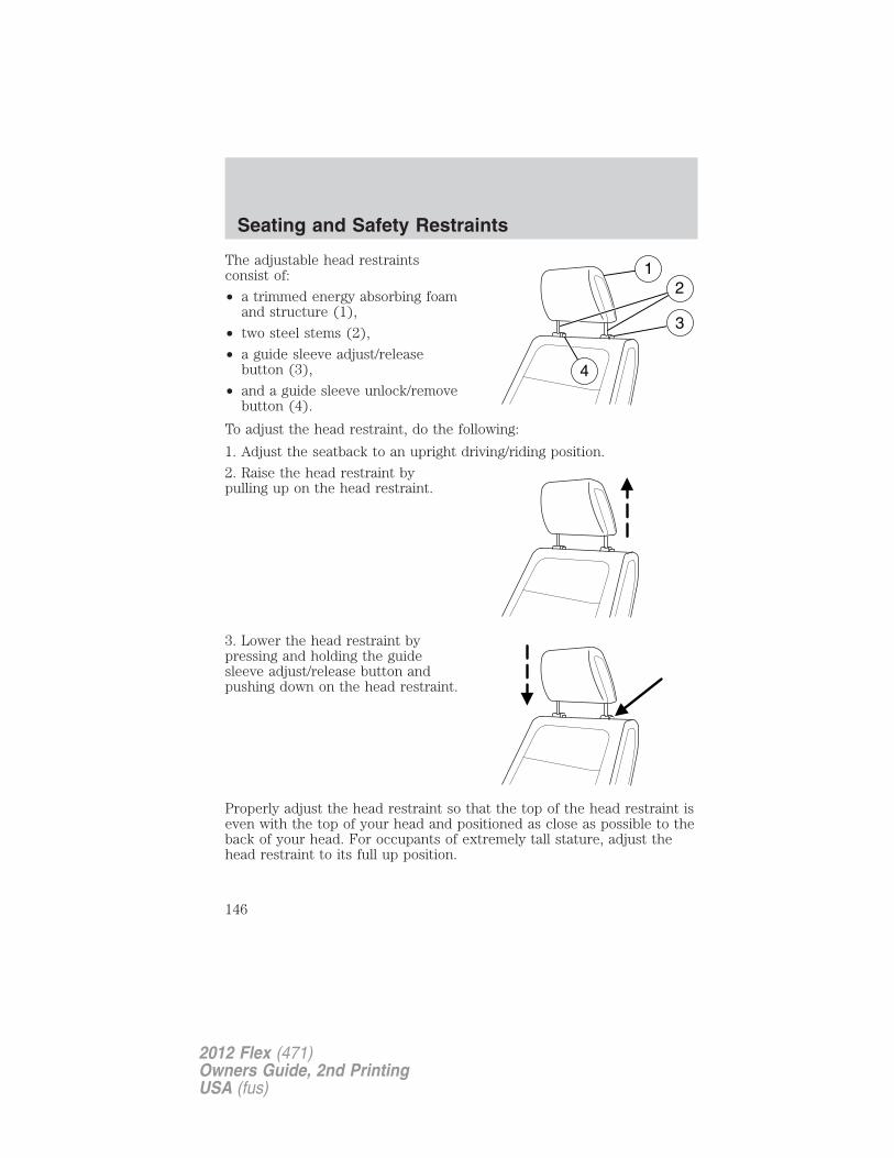
The adjustable head restraintsconsist of:
• a trimmed energy absorbing foamand structure (1),
• two steel stems (2),
• a guide sleeve adjust/releasebutton (3),
• and a guide sleeve unlock/removebutton (4).
To adjust the head restraint, do the following:
1. Adjust the seatback to an upright driving/riding position.
2. Raise the head restraint bypulling up on the head restraint.
3. Lower the head restraint bypressing and holding the guidesleeve adjust/release button andpushing down on the head restraint.
Properly adjust the head restraint so that the top of the head restraint iseven with the top of your head and positioned as close as possible to theback of your head. For occupants of extremely tall stature, adjust thehead restraint to its full up position.
Seating and Safety Restraints
146
2012 Flex (471)Owners Guide, 2nd PrintingUSA (fus)
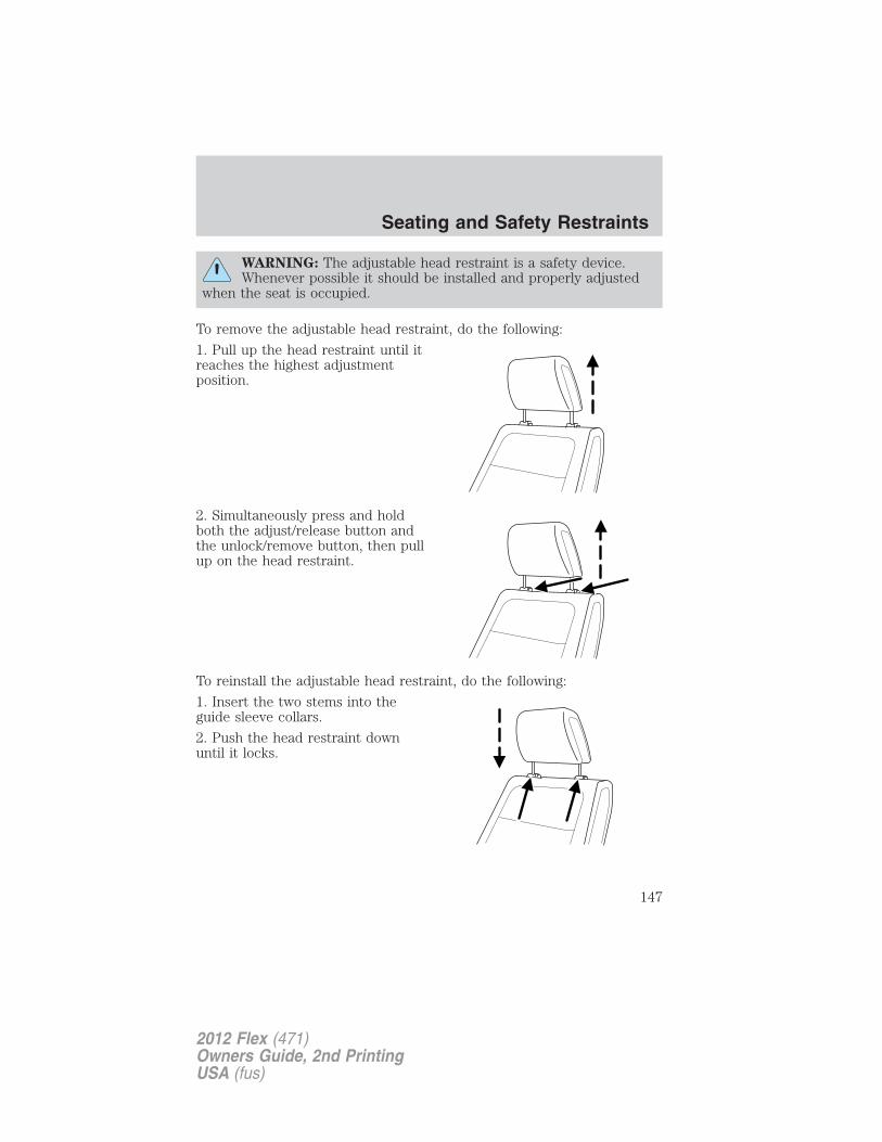
WARNING: The adjustable head restraint is a safety device.Whenever possible it should be installed and properly adjusted
when the seat is occupied.
To remove the adjustable head restraint, do the following:
1. Pull up the head restraint until itreaches the highest adjustmentposition.
2. Simultaneously press and holdboth the adjust/release button andthe unlock/remove button, then pullup on the head restraint.
To reinstall the adjustable head restraint, do the following:
1. Insert the two stems into theguide sleeve collars.
2. Push the head restraint downuntil it locks.
Seating and Safety Restraints
147
2012 Flex (471)Owners Guide, 2nd PrintingUSA (fus)
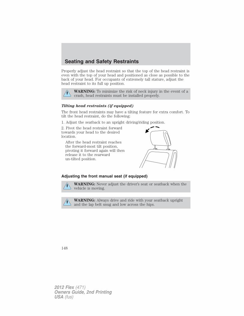
Properly adjust the head restraint so that the top of the head restraint iseven with the top of your head and positioned as close as possible to theback of your head. For occupants of extremely tall stature, adjust thehead restraint to its full up position.
WARNING: To minimize the risk of neck injury in the event of acrash, head restraints must be installed properly.
Tilting head restraints (if equipped)
The front head restraints may have a tilting feature for extra comfort. Totilt the head restraint, do the following:
1. Adjust the seatback to an upright driving/riding position.
2. Pivot the head restraint forwardtowards your head to the desiredlocation.
After the head restraint reachesthe forward-most tilt position,pivoting it forward again will thenrelease it to the rearwardun-tilted position.
Adjusting the front manual seat (if equipped)
WARNING: Never adjust the driver’s seat or seatback when thevehicle is moving.
WARNING: Always drive and ride with your seatback uprightand the lap belt snug and low across the hips.
Seating and Safety Restraints
148
2012 Flex (471)Owners Guide, 2nd PrintingUSA (fus)
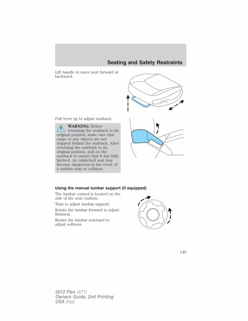
Lift handle to move seat forward orbackward.
Pull lever up to adjust seatback.
WARNING: Beforereturning the seatback to its
original position, make sure thatcargo or any objects are nottrapped behind the seatback. Afterreturning the seatback to itsoriginal position, pull on theseatback to ensure that it has fullylatched. An unlatched seat maybecome dangerous in the event ofa sudden stop or collision.
Using the manual lumbar support (if equipped)The lumbar control is located on theside of the seat cushion.
Turn to adjust lumbar support.
Rotate the lumbar forward to adjustfirmness.
Rotate the lumbar rearward toadjust softness.
Seating and Safety Restraints
149
2012 Flex (471)Owners Guide, 2nd PrintingUSA (fus)
Adjusting the front power seat (if equipped)
WARNING: Never adjust the driver’s seat or seatback when thevehicle is moving.
WARNING: Do not pile cargo higher than the seatbacks toreduce the risk of injury in a collision or sudden stop.
WARNING: Always drive and ride with your seatback uprightand the lap belt snug and low across the hips.
WARNING: Reclining the seatback can cause an occupant toslide under the seat’s safety belt, resulting in severe personal
injuries in the event of a collision.
WARNING: Sitting improperly out of position or with the seatback reclined too far can take off weight from the seat cushion
and affect the decision of the passenger sensing system, resulting inserious injury or death in a crash. Always sit upright against yourseatback, with your feet on the floor.
WARNING: To reduce the risk of possible serious injury: Do nothang objects off seat back or stow objects in the seatback map
pocket (if equipped) when a child is in the front passenger seat. Donot place objects underneath the front passenger seat or between theseat and the center console (if equipped). Check the “passenger airbagoff” or “pass airbag off” indicator lamp for proper airbag status. Referto Front passenger sensing system in the Airbag supplementalrestraint system (SRS) section for additional details. Failure to followthese instructions may interfere with the front passenger seat sensingsystem.
Seating and Safety Restraints
150
2012 Flex (471)Owners Guide, 2nd PrintingUSA (fus)
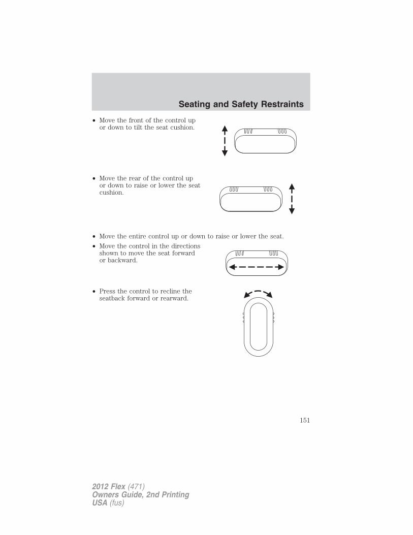
• Move the front of the control upor down to tilt the seat cushion.
• Move the rear of the control upor down to raise or lower the seatcushion.
• Move the entire control up or down to raise or lower the seat.
• Move the control in the directionsshown to move the seat forwardor backward.
• Press the control to recline theseatback forward or rearward.
Seating and Safety Restraints
151
2012 Flex (471)Owners Guide, 2nd PrintingUSA (fus)
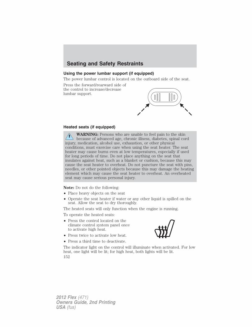
Using the power lumbar support (if equipped)The power lumbar control is located on the outboard side of the seat.
Press the forward/rearward side ofthe control to increase/decreaselumbar support.
Heated seats (if equipped)
WARNING: Persons who are unable to feel pain to the skinbecause of advanced age, chronic illness, diabetes, spinal cord
injury, medication, alcohol use, exhaustion, or other physicalconditions, must exercise care when using the seat heater. The seatheater may cause burns even at low temperatures, especially if usedfor long periods of time. Do not place anything on the seat thatinsulates against heat, such as a blanket or cushion, because this maycause the seat heater to overheat. Do not puncture the seat with pins,needles, or other pointed objects because this may damage the heatingelement which may cause the seat heater to overheat. An overheatedseat may cause serious personal injury.
Note: Do not do the following:• Place heavy objects on the seat• Operate the seat heater if water or any other liquid is spilled on the
seat. Allow the seat to dry thoroughly.
The heated seats will only function when the engine is running.
To operate the heated seats:
• Press the control located on theclimate control system panel onceto activate high heat.
• Press twice to activate low heat.
• Press a third time to deactivate.
The indicator light on the control will illuminate when activated. For lowheat, one light will be lit; for high heat, both lights will be lit.
Seating and Safety Restraints
152
2012 Flex (471)Owners Guide, 2nd PrintingUSA (fus)
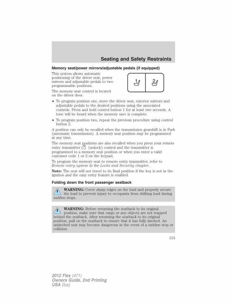
Memory seat/power mirrors/adjustable pedals (if equipped)This system allows automaticpositioning of the driver seat, powermirrors and adjustable pedals to twoprogrammable positions.
The memory seat control is locatedon the driver door.
• To program position one, move the driver seat, exterior mirrors andadjustable pedals to the desired positions using the associatedcontrols. Press and hold control button 1 for at least two seconds. Atone will be heard when the memory save is complete.
• To program position two, repeat the previous procedure using controlbutton 2.
A position can only be recalled when the transmission gearshift is in Park(automatic transmission). A memory seat position may be programmedat any time.
The memory seat positions are also recalled when you press your remoteentry transmitter (unlock) control and the transmitter isprogrammed to a memory seat position or when you enter a validcustomer code 1 or 2 on the keypad.
To program the memory seat to remote entry transmitter, refer toRemote entry system in the Locks and Security chapter..
Note: The seat will not travel to its final position if the key is not in theignition and the easy entry feature is enabled.
Folding down the front passenger seatback
WARNING: Cover sharp edges on the load and properly securethe load to prevent injury to occupants from shifting load during
sudden stops.
WARNING: Before returning the seatback to its originalposition, make sure that cargo or any objects are not trapped
behind the seatback. After returning the seatback to its originalposition, pull on the seatback to ensure that it has fully latched. Anunlatched seat may become dangerous in the event of a sudden stop orcollision.
Seating and Safety Restraints
153
2012 Flex (471)Owners Guide, 2nd PrintingUSA (fus)
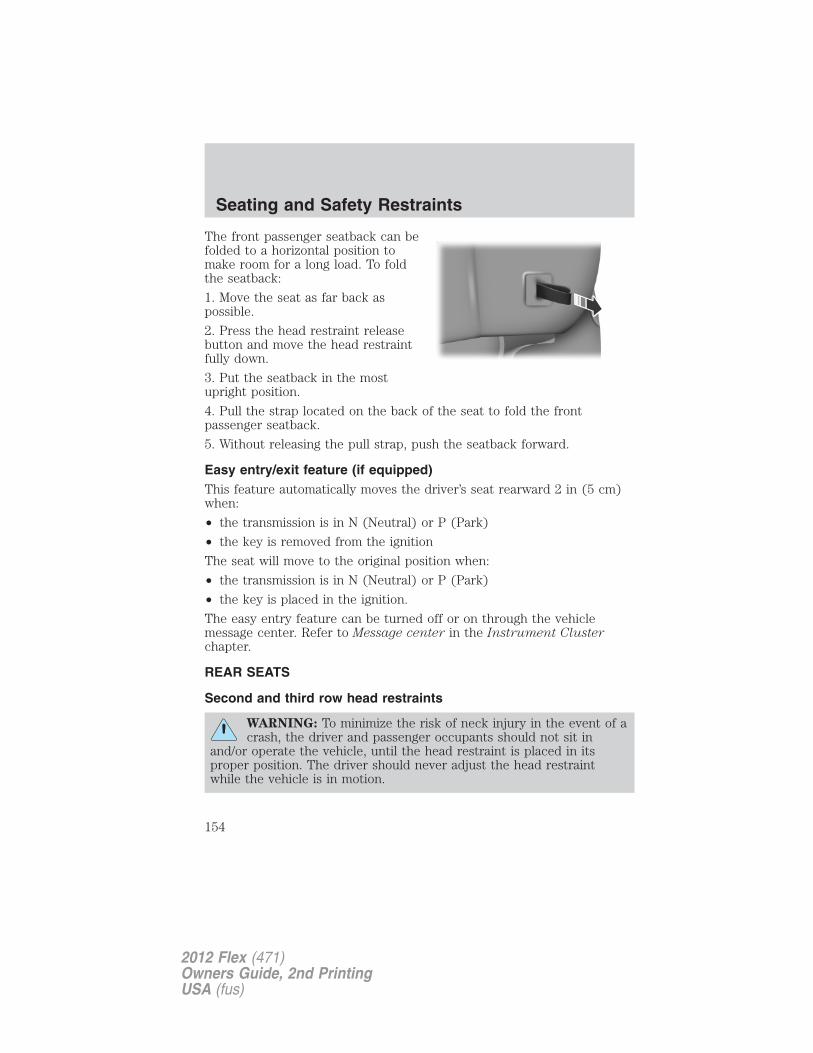
The front passenger seatback can befolded to a horizontal position tomake room for a long load. To foldthe seatback:
1. Move the seat as far back aspossible.
2. Press the head restraint releasebutton and move the head restraintfully down.
3. Put the seatback in the mostupright position.
4. Pull the strap located on the back of the seat to fold the frontpassenger seatback.
5. Without releasing the pull strap, push the seatback forward.
Easy entry/exit feature (if equipped)This feature automatically moves the driver’s seat rearward 2 in (5 cm)when:
• the transmission is in N (Neutral) or P (Park)
• the key is removed from the ignition
The seat will move to the original position when:
• the transmission is in N (Neutral) or P (Park)
• the key is placed in the ignition.
The easy entry feature can be turned off or on through the vehiclemessage center. Refer to Message center in the Instrument Clusterchapter.
REAR SEATS
Second and third row head restraints
WARNING: To minimize the risk of neck injury in the event of acrash, the driver and passenger occupants should not sit in
and/or operate the vehicle, until the head restraint is placed in itsproper position. The driver should never adjust the head restraintwhile the vehicle is in motion.
Seating and Safety Restraints
154
2012 Flex (471)Owners Guide, 2nd PrintingUSA (fus)
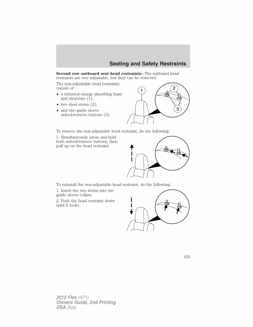
Second row outboard seat head restraints– The outboard headrestraints are non adjustable, but they can be removed.
The non-adjustable head restraintsconsist of :
• a trimmed energy absorbing foamand structure (1),
• two steel stems (2),
• and two guide sleeveunlock/remove buttons (3).
To remove the non-adjustable head restraint, do the following:
1. Simultaneously press and holdboth unlock/remove buttons, thenpull up on the head restraint.
To reinstall the non-adjustable head restraint, do the following:
1. Insert the two stems into theguide sleeve collars.
2. Push the head restraint downuntil it locks.
Seating and Safety Restraints
155
2012 Flex (471)Owners Guide, 2nd PrintingUSA (fus)
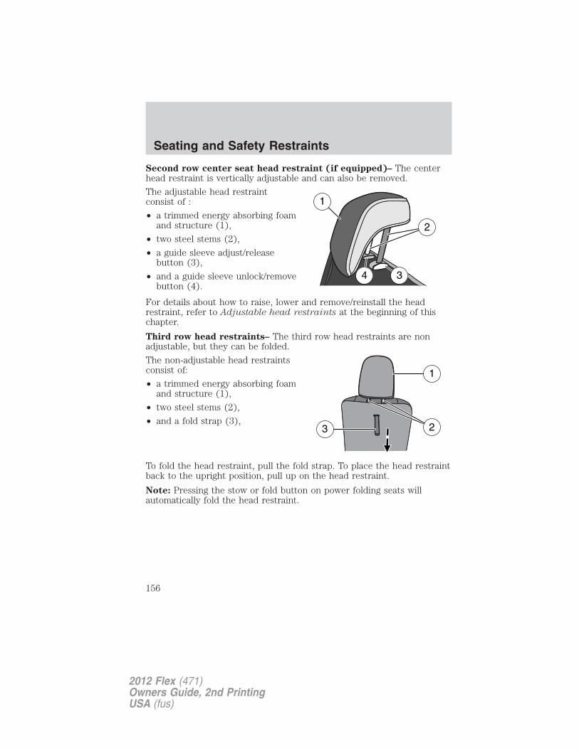
Second row center seat head restraint (if equipped)– The centerhead restraint is vertically adjustable and can also be removed.
The adjustable head restraintconsist of :
• a trimmed energy absorbing foamand structure (1),
• two steel stems (2),
• a guide sleeve adjust/releasebutton (3),
• and a guide sleeve unlock/removebutton (4).
For details about how to raise, lower and remove/reinstall the headrestraint, refer to Adjustable head restraints at the beginning of thischapter.
Third row head restraints– The third row head restraints are nonadjustable, but they can be folded.
The non-adjustable head restraintsconsist of:
• a trimmed energy absorbing foamand structure (1),
• two steel stems (2),
• and a fold strap (3),
To fold the head restraint, pull the fold strap. To place the head restraintback to the upright position, pull up on the head restraint.
Note: Pressing the stow or fold button on power folding seats willautomatically fold the head restraint.
1
34
2
1
3 2
Seating and Safety Restraints
156
2012 Flex (471)Owners Guide, 2nd PrintingUSA (fus)
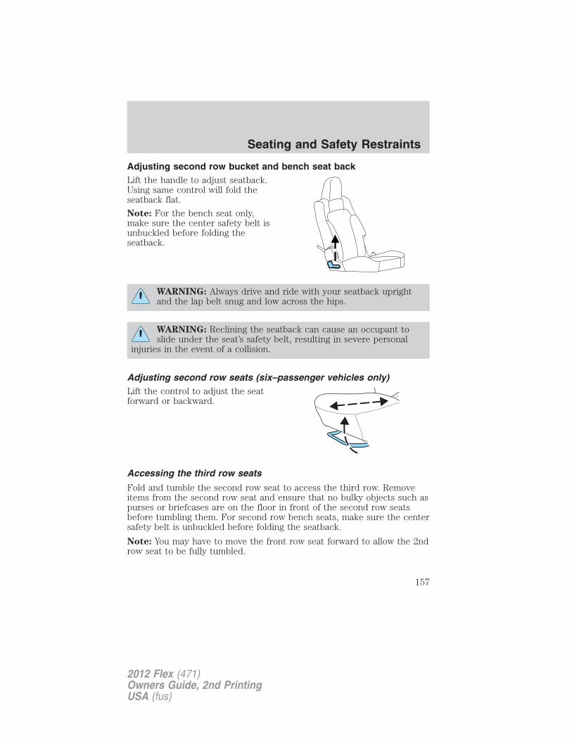
Adjusting second row bucket and bench seat backLift the handle to adjust seatback.Using same control will fold theseatback flat.
Note: For the bench seat only,make sure the center safety belt isunbuckled before folding theseatback.
WARNING: Always drive and ride with your seatback uprightand the lap belt snug and low across the hips.
WARNING: Reclining the seatback can cause an occupant toslide under the seat’s safety belt, resulting in severe personal
injuries in the event of a collision.
Adjusting second row seats (six–passenger vehicles only)Lift the control to adjust the seatforward or backward.
Accessing the third row seats
Fold and tumble the second row seat to access the third row. Removeitems from the second row seat and ensure that no bulky objects such aspurses or briefcases are on the floor in front of the second row seatsbefore tumbling them. For second row bench seats, make sure the centersafety belt is unbuckled before folding the seatback.
Note: You may have to move the front row seat forward to allow the 2ndrow seat to be fully tumbled.
Seating and Safety Restraints
157
2012 Flex (471)Owners Guide, 2nd PrintingUSA (fus)
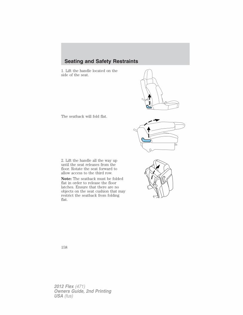
1. Lift the handle located on theside of the seat.
The seatback will fold flat.
2. Lift the handle all the way upuntil the seat releases from thefloor. Rotate the seat forward toallow access to the third row.
Note: The seatback must be foldedflat in order to release the floorlatches. Ensure that there are noobjects on the seat cushion that mayrestrict the seatback from foldingflat.
Seating and Safety Restraints
158
2012 Flex (471)Owners Guide, 2nd PrintingUSA (fus)
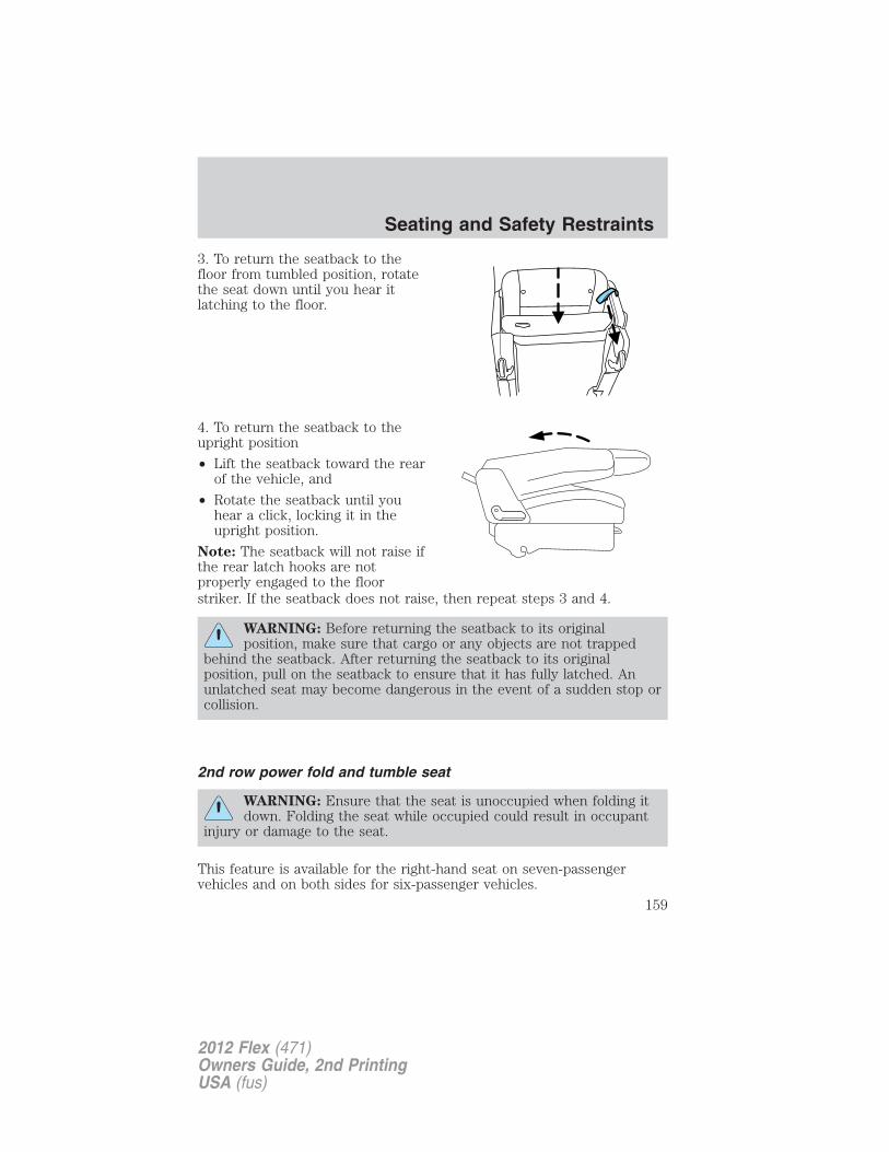
3. To return the seatback to thefloor from tumbled position, rotatethe seat down until you hear itlatching to the floor.
4. To return the seatback to theupright position
• Lift the seatback toward the rearof the vehicle, and
• Rotate the seatback until youhear a click, locking it in theupright position.
Note: The seatback will not raise ifthe rear latch hooks are notproperly engaged to the floorstriker. If the seatback does not raise, then repeat steps 3 and 4.
WARNING: Before returning the seatback to its originalposition, make sure that cargo or any objects are not trapped
behind the seatback. After returning the seatback to its originalposition, pull on the seatback to ensure that it has fully latched. Anunlatched seat may become dangerous in the event of a sudden stop orcollision.
2nd row power fold and tumble seat
WARNING: Ensure that the seat is unoccupied when folding itdown. Folding the seat while occupied could result in occupant
injury or damage to the seat.
This feature is available for the right-hand seat on seven-passengervehicles and on both sides for six-passenger vehicles.
Seating and Safety Restraints
159
2012 Flex (471)Owners Guide, 2nd PrintingUSA (fus)
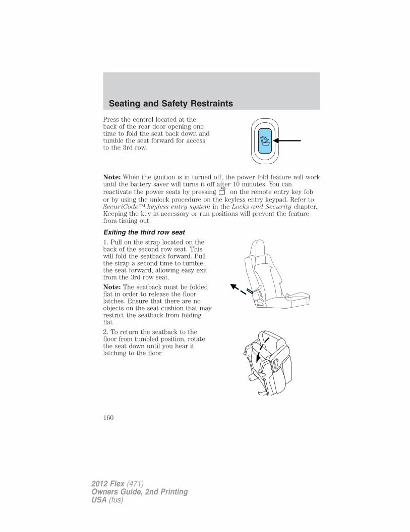
Press the control located at theback of the rear door opening onetime to fold the seat back down andtumble the seat forward for accessto the 3rd row.
Note: When the ignition is in turned off, the power fold feature will workuntil the battery saver will turns it off after 10 minutes. You canreactivate the power seats by pressing on the remote entry key fobor by using the unlock procedure on the keyless entry keypad. Refer toSecuriCode™ keyless entry system in the Locks and Security chapter.Keeping the key in accessory or run positions will prevent the featurefrom timing out.
Exiting the third row seat1. Pull on the strap located on theback of the second row seat. Thiswill fold the seatback forward. Pullthe strap a second time to tumblethe seat forward, allowing easy exitfrom the 3rd row seat.
Note: The seatback must be foldedflat in order to release the floorlatches. Ensure that there are noobjects on the seat cushion that mayrestrict the seatback from foldingflat.
2. To return the seatback to thefloor from tumbled position, rotatethe seat down until you hear itlatching to the floor.
Seating and Safety Restraints
160
2012 Flex (471)Owners Guide, 2nd PrintingUSA (fus)
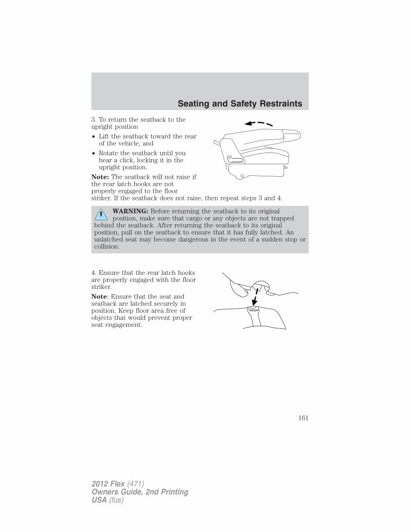
3. To return the seatback to theupright position
• Lift the seatback toward the rearof the vehicle, and
• Rotate the seatback until youhear a click, locking it in theupright position.
Note: The seatback will not raise ifthe rear latch hooks are notproperly engaged to the floorstriker. If the seatback does not raise, then repeat steps 3 and 4.
WARNING: Before returning the seatback to its originalposition, make sure that cargo or any objects are not trapped
behind the seatback. After returning the seatback to its originalposition, pull on the seatback to ensure that it has fully latched. Anunlatched seat may become dangerous in the event of a sudden stop orcollision.
4. Ensure that the rear latch hooksare properly engaged with the floorstriker.
Note: Ensure that the seat andseatback are latched securely inposition. Keep floor area free ofobjects that would prevent properseat engagement.
Seating and Safety Restraints
161
2012 Flex (471)Owners Guide, 2nd PrintingUSA (fus)
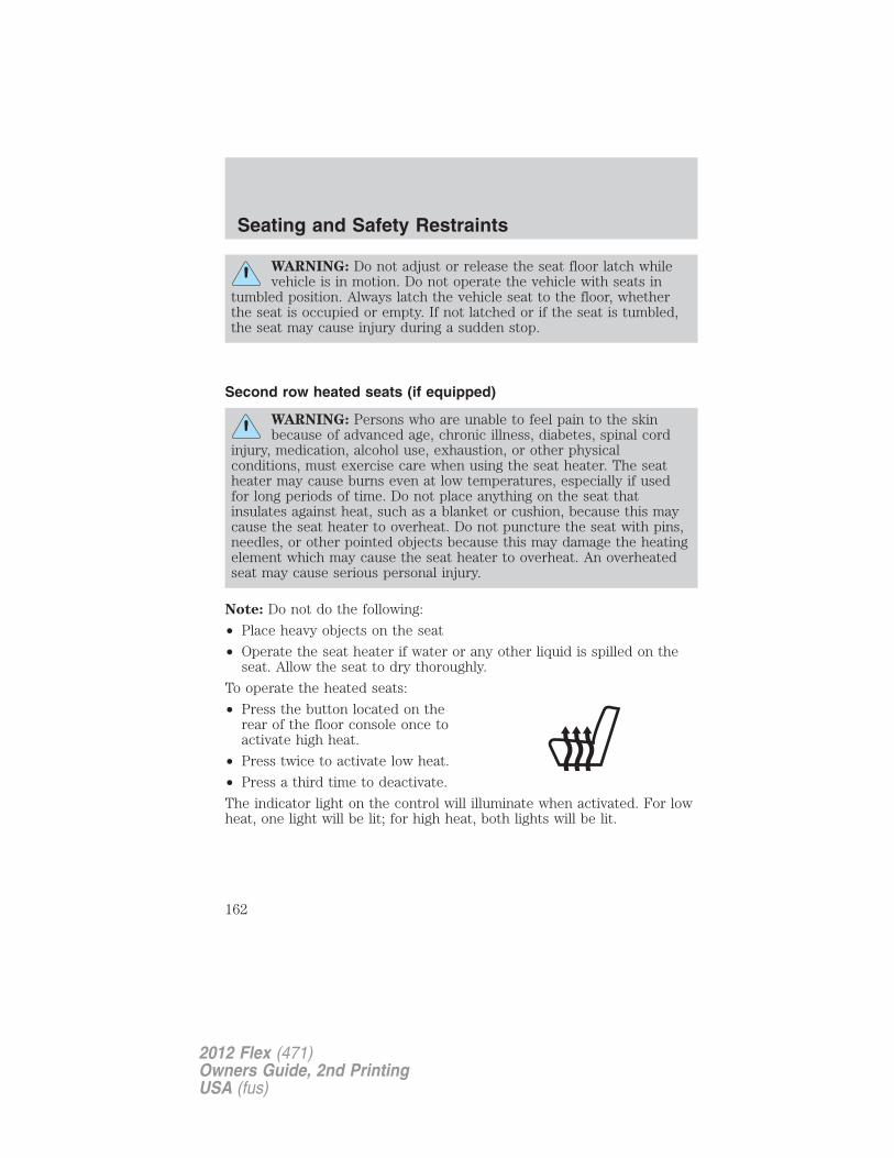
WARNING: Do not adjust or release the seat floor latch whilevehicle is in motion. Do not operate the vehicle with seats in
tumbled position. Always latch the vehicle seat to the floor, whetherthe seat is occupied or empty. If not latched or if the seat is tumbled,the seat may cause injury during a sudden stop.
Second row heated seats (if equipped)
WARNING: Persons who are unable to feel pain to the skinbecause of advanced age, chronic illness, diabetes, spinal cord
injury, medication, alcohol use, exhaustion, or other physicalconditions, must exercise care when using the seat heater. The seatheater may cause burns even at low temperatures, especially if usedfor long periods of time. Do not place anything on the seat thatinsulates against heat, such as a blanket or cushion, because this maycause the seat heater to overheat. Do not puncture the seat with pins,needles, or other pointed objects because this may damage the heatingelement which may cause the seat heater to overheat. An overheatedseat may cause serious personal injury.
Note: Do not do the following:
• Place heavy objects on the seat
• Operate the seat heater if water or any other liquid is spilled on theseat. Allow the seat to dry thoroughly.
To operate the heated seats:
• Press the button located on therear of the floor console once toactivate high heat.
• Press twice to activate low heat.
• Press a third time to deactivate.
The indicator light on the control will illuminate when activated. For lowheat, one light will be lit; for high heat, both lights will be lit.
Seating and Safety Restraints
162
2012 Flex (471)Owners Guide, 2nd PrintingUSA (fus)
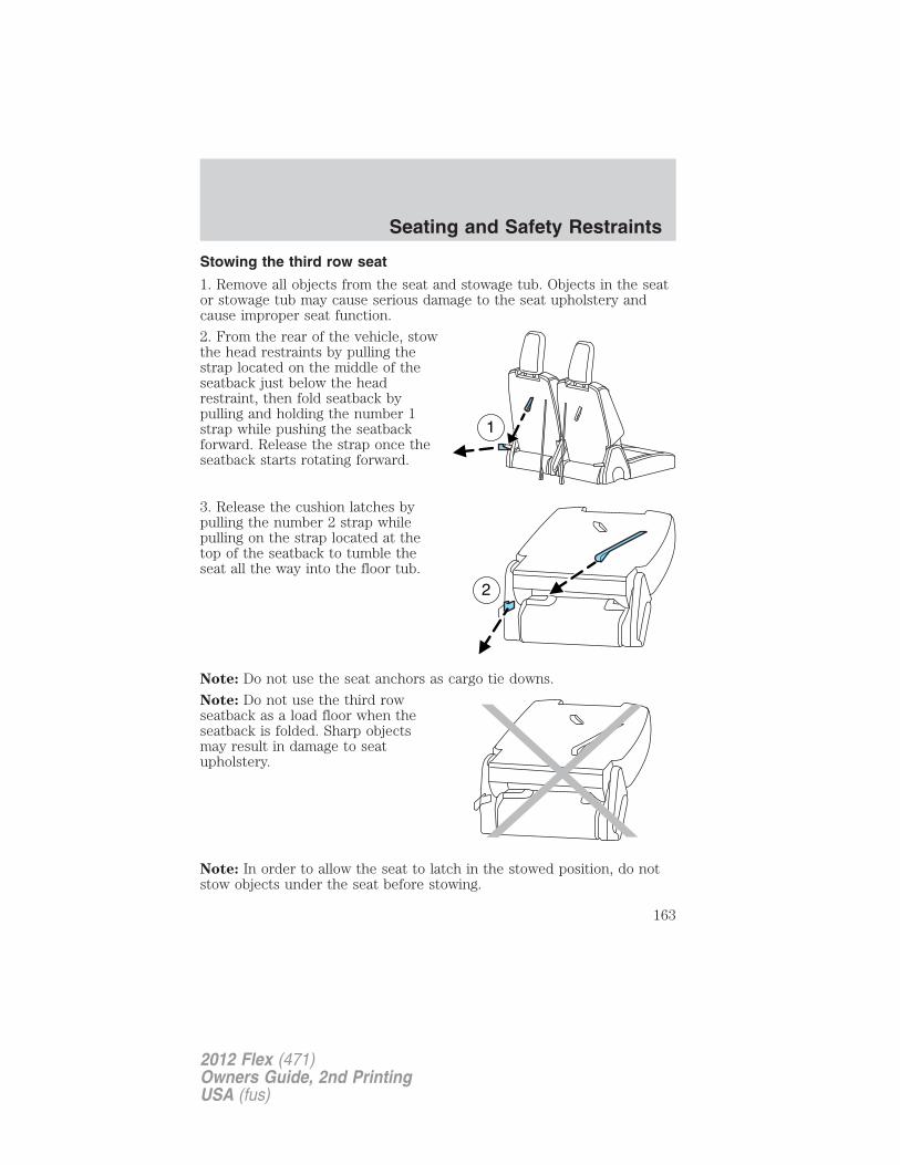
Stowing the third row seat
1. Remove all objects from the seat and stowage tub. Objects in the seator stowage tub may cause serious damage to the seat upholstery andcause improper seat function.
2. From the rear of the vehicle, stowthe head restraints by pulling thestrap located on the middle of theseatback just below the headrestraint, then fold seatback bypulling and holding the number 1strap while pushing the seatbackforward. Release the strap once theseatback starts rotating forward.
3. Release the cushion latches bypulling the number 2 strap whilepulling on the strap located at thetop of the seatback to tumble theseat all the way into the floor tub.
Note: Do not use the seat anchors as cargo tie downs.
Note: Do not use the third rowseatback as a load floor when theseatback is folded. Sharp objectsmay result in damage to seatupholstery.
Note: In order to allow the seat to latch in the stowed position, do notstow objects under the seat before stowing.
Seating and Safety Restraints
163
2012 Flex (471)Owners Guide, 2nd PrintingUSA (fus)
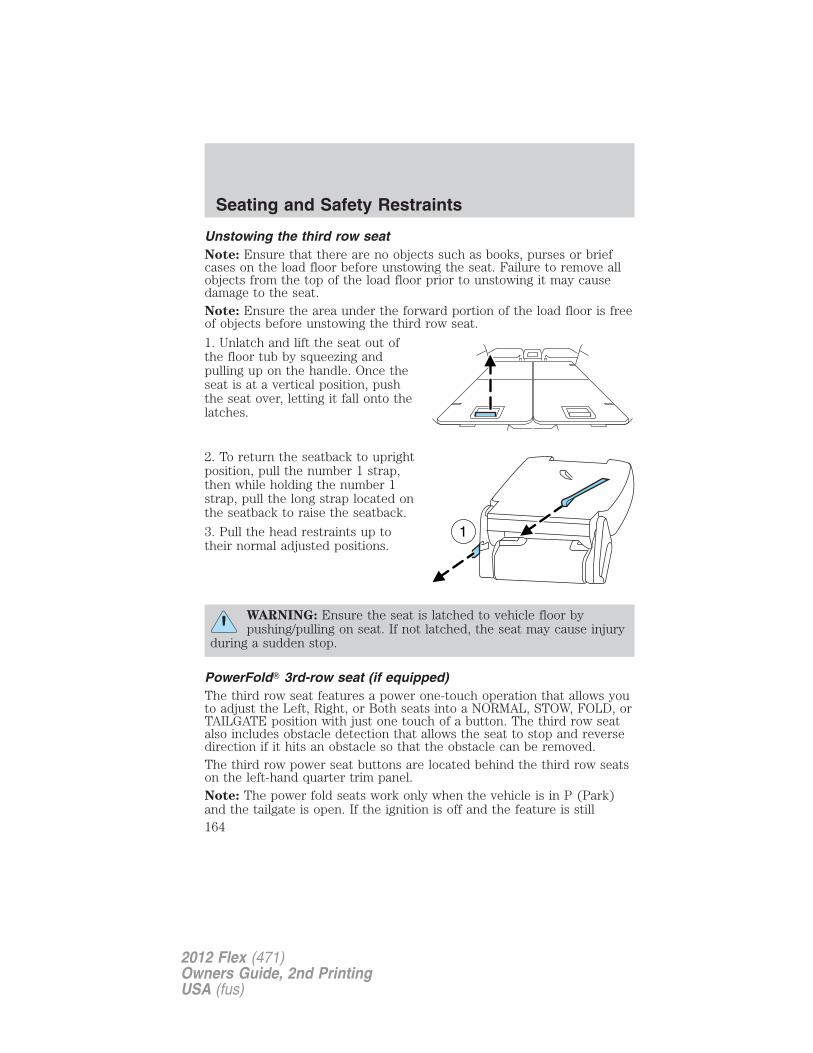
Unstowing the third row seatNote: Ensure that there are no objects such as books, purses or briefcases on the load floor before unstowing the seat. Failure to remove allobjects from the top of the load floor prior to unstowing it may causedamage to the seat.Note: Ensure the area under the forward portion of the load floor is freeof objects before unstowing the third row seat.
1. Unlatch and lift the seat out ofthe floor tub by squeezing andpulling up on the handle. Once theseat is at a vertical position, pushthe seat over, letting it fall onto thelatches.
2. To return the seatback to uprightposition, pull the number 1 strap,then while holding the number 1strap, pull the long strap located onthe seatback to raise the seatback.
3. Pull the head restraints up totheir normal adjusted positions.
WARNING: Ensure the seat is latched to vehicle floor bypushing/pulling on seat. If not latched, the seat may cause injury
during a sudden stop.
PowerFold� 3rd-row seat (if equipped)The third row seat features a power one-touch operation that allows youto adjust the Left, Right, or Both seats into a NORMAL, STOW, FOLD, orTAILGATE position with just one touch of a button. The third row seatalso includes obstacle detection that allows the seat to stop and reversedirection if it hits an obstacle so that the obstacle can be removed.The third row power seat buttons are located behind the third row seatson the left-hand quarter trim panel.Note: The power fold seats work only when the vehicle is in P (Park)and the tailgate is open. If the ignition is off and the feature is still
Seating and Safety Restraints
164
2012 Flex (471)Owners Guide, 2nd PrintingUSA (fus)
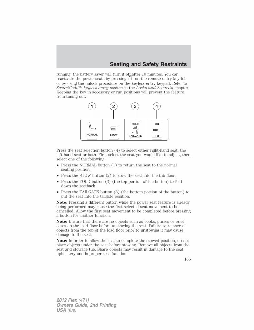
running, the battery saver will turn it off after 10 minutes. You canreactivate the power seats by pressing on the remote entry key fobor by using the unlock procedure on the keyless entry keypad. Refer toSecuriCode™ keyless entry system in the Locks and Security chapter.Keeping the key in accessory or run positions will prevent the featurefrom timing out.
Press the seat selection button (4) to select either right-hand seat, theleft-hand seat or both. First select the seat you would like to adjust, thenselect one of the following:
• Press the NORMAL button (1) to return the seat to the normalseating position.
• Press the STOW button (2) to stow the seat into the tub floor.
• Press the FOLD button (3) (the top portion of the button) to folddown the seatback.
• Press the TAILGATE button (3) (the bottom portion of the button) toput the seat into the tailgate position.
Note: Pressing a different button while the power seat feature is alreadybeing performed may cause the first selected seat movement to becancelled. Allow the first seat movement to be completed before pressinga button for another function.
Note: Ensure that there are no objects such as books, purses or briefcases on the load floor before unstowing the seat. Failure to remove allobjects from the top of the load floor prior to unstowing it may causedamage to the seat.
Note: In order to allow the seat to complete the stowed position, do notplace objects under the seat before stowing. Remove all objects from theseat and stowage tub. Sharp objects may result in damage to the seatupholstery and improper seat function.
1 2 3 4
NORMAL STOW
RH
BOTH
LH
FOLD
TAILGATE
Seating and Safety Restraints
165
2012 Flex (471)Owners Guide, 2nd PrintingUSA (fus)
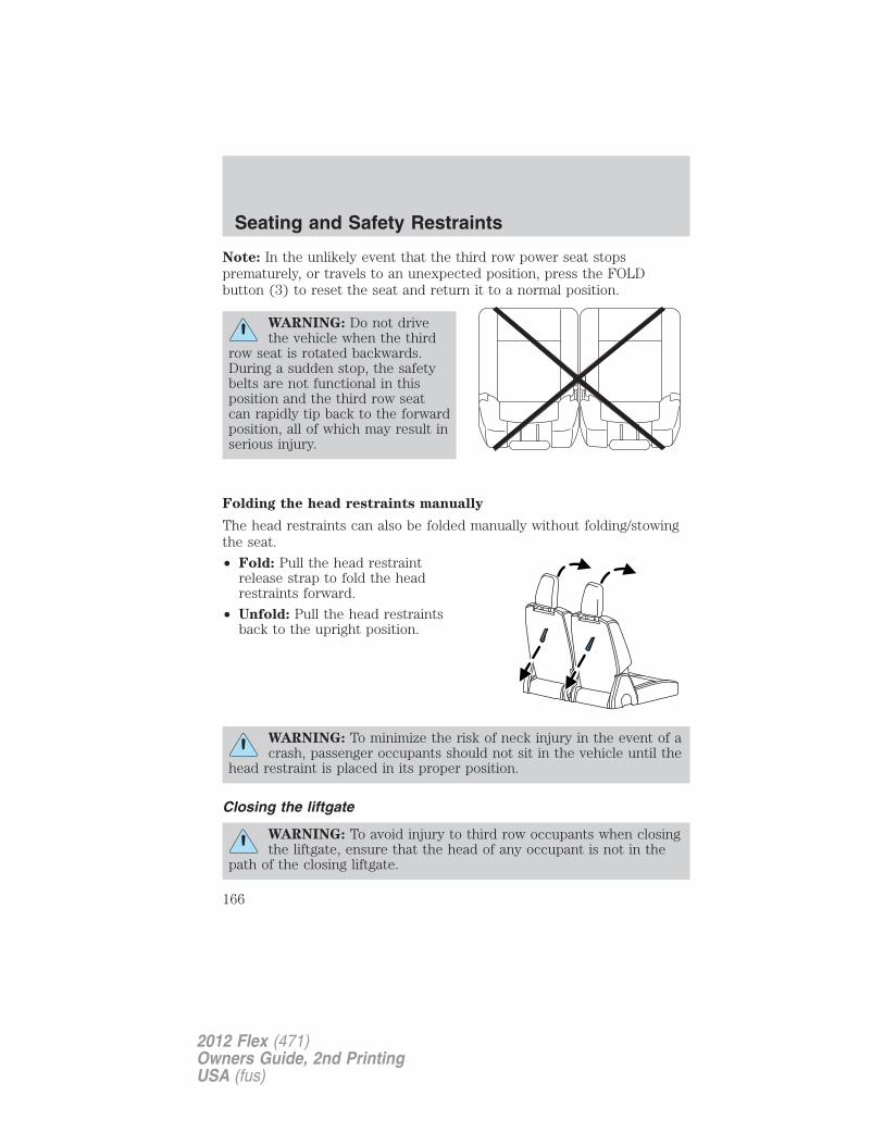
Note: In the unlikely event that the third row power seat stopsprematurely, or travels to an unexpected position, press the FOLDbutton (3) to reset the seat and return it to a normal position.
WARNING: Do not drivethe vehicle when the third
row seat is rotated backwards.During a sudden stop, the safetybelts are not functional in thisposition and the third row seatcan rapidly tip back to the forwardposition, all of which may result inserious injury.
Folding the head restraints manually
The head restraints can also be folded manually without folding/stowingthe seat.
• Fold: Pull the head restraintrelease strap to fold the headrestraints forward.
• Unfold: Pull the head restraintsback to the upright position.
WARNING: To minimize the risk of neck injury in the event of acrash, passenger occupants should not sit in the vehicle until the
head restraint is placed in its proper position.
Closing the liftgate
WARNING: To avoid injury to third row occupants when closingthe liftgate, ensure that the head of any occupant is not in the
path of the closing liftgate.
Seating and Safety Restraints
166
2012 Flex (471)Owners Guide, 2nd PrintingUSA (fus)
PERSONAL SAFETY SYSTEM™The Personal Safety System provides an improved overall level of frontalcrash protection to front seat occupants and is designed to help furtherreduce the risk of airbag-related injuries. The system is able to analyzedifferent occupant conditions and crash severity before activating theappropriate safety devices to help better protect a range of occupants ina variety of frontal crash situations.Your vehicle’s Personal Safety System consists of:• Driver and passenger dual-stage airbag supplemental restraints.
• Front outboard safety belts with pretensioners, energy managementretractors (first row only), and safety belt usage sensors.
• Driver’s seat position sensor.
• Front passenger sensing system
• “Passenger airbag off” or “pass airbag off” indicator lamp
• Front crash severity sensor.
• Restraints Control Module (RCM) with impact and safing sensors.
• Restraint system warning light and back-up tone.
• The electrical wiring for the airbags, crash sensor(s), safety beltpretensioners, front safety belt usage sensors, driver seat positionsensor, front passenger sensing system, and indicator lights.
How does the Personal Safety System™ work?The Personal Safety System can adapt the deployment strategy of yourvehicle’s safety devices according to crash severity and occupantconditions. A collection of crash and occupant sensors providesinformation to the Restraints Control Module (RCM). During a crash, theRCM activates the safety belt pretensioners and/or either one or bothstages of the dual-stage airbag supplemental restraints based on crashseverity and occupant conditions.
The fact that the pretensioners or airbags did not activate for both frontseat occupants in a collision does not mean that something is wrong withthe system. Rather, it means the Personal Safety System determined theaccident conditions (crash severity, belt usage, etc.) were notappropriate to activate these safety devices. Front airbags are designedto activate only in frontal and near-frontal collisions (not rollovers, sideimpacts or rear impacts) unless the collision causes sufficientlongitudinal deceleration. The pretensioners are designed to activate infrontal and near-frontal collisions, and in side collisions and rollovers.
Seating and Safety Restraints
167
2012 Flex (471)Owners Guide, 2nd PrintingUSA (fus)
Driver and passenger dual-stage airbag supplemental restraintsThe dual-stage airbags offer the capability to tailor the level of airbaginflation energy. A lower, less forceful energy level is provided for morecommon, moderate-severity impacts. A higher energy level is used forthe most severe impacts. Refer to Airbag supplemental restraints(SRS) section in this chapter.
Front crash severity sensorThe front crash severity sensor enhances the ability to detect theseverity of an impact. Positioned up front, it provides valuableinformation early in the crash event on the severity of the impact. Thisallows your Personal Safety System to distinguish between differentlevels of crash severity and modify the deployment strategy of thedual-stage airbags and safety belt pretensioners.
Driver’s seat position sensorThe driver’s seat position sensor allows your Personal Safety System totailor the deployment level of the driver dual-stage airbag based on seatposition. The system is designed to help protect smaller drivers sittingclose to the driver airbag by providing a lower airbag output level.
Front passenger sensing systemFor airbags to do their job they must inflate with great force, and thisforce can pose a potentially deadly risk to occupants that are very closeto the airbag when it begins to inflate. For some occupants, this occursbecause they are initially sitting very close to the airbag. For otheroccupants, this occurs when the occupant is not properly restrained bysafety belts or child safety seats and they move forward during pre-crashbraking. The most effective way to reduce the risk of unnecessaryinjuries is to make sure all occupants are properly restrained. Accidentstatistics suggest that children are much safer when properly restrainedin the rear seating positions than in the front.
WARNING: Air bags can kill or injure a child in a child seat.NEVER place a rear-facing child seat in front of an active air
bag. If you must use a forward-facing child seat in the front seat, movethe seat all the way back.
WARNING: When possible, all children 12 years old and undershould be properly restrained in a rear seating position.
The front passenger sensing system can automatically turn off thepassenger front airbag. The system is designed to help protect small
Seating and Safety Restraints
168
2012 Flex (471)Owners Guide, 2nd PrintingUSA (fus)
(child size) occupants from airbag deployments when they areimproperly seated or restrained in the front passenger seat contrary toproper child-seating or restraint usage recommendations. Even with thistechnology, parents are STRONGLY encouraged to always properlyrestrain children in the rear seat. The sensor also turns off the passengerfront airbag and seat-mounted side airbag when the passenger seat isempty to prevent unnecessary replacement of airbag(s) after a collision.
Front safety belt usage sensorsThe front safety belt usage sensors detect whether or not the driver andfront outboard passenger safety belts are fastened. This informationallows your Personal Safety System to tailor the airbag deployment andsafety belt pretensioner activation depending upon safety belt usage.
Front safety belt pretensionersThe safety belt pretensioners at the front outboard seating positions aredesigned to tighten the safety belts firmly against the occupant’s bodyduring frontal collisions, and in side collisions and rollovers. This helpsincrease the effectiveness of the safety belts. In frontal collisions, thesafety belt pretensioners can be activated alone or, if the collision is ofsufficient severity, together with the front airbags.
Front safety belt energy management retractorsThe front outboard safety belt energy management retractors allowwebbing to be pulled out of the retractor in a gradual and controlledmanner in response to the occupant’s forward momentum. This helpsreduce the risk of force-related injuries to the occupant’s chest bylimiting the load on the occupant. Refer to Energy managementfeature- front outboard section in this chapter.
Determining if the Personal Safety System is operationalThe Personal Safety System uses a warning light in the instrumentcluster or a back-up tone to indicate the condition of the system. Referto the Warning lights and chimes section in the Instrument Clusterchapter. Routine maintenance of the Personal Safety System is notrequired.
The Restraints Control Module (RCM) monitors its own internal circuitsand the circuits for the airbag supplemental restraints, crash sensor(s),safety belt pretensioners, front safety belt buckle sensors, driver seatposition sensor, and front passenger sensing system. In addition, theRCM also monitors the restraints warning light in the instrument cluster.A difficulty with the system is indicated by one or more of the following.
Seating and Safety Restraints
169
2012 Flex (471)Owners Guide, 2nd PrintingUSA (fus)
• The warning light will either flash or stay lit.
• The warning light will not illuminate immediately after ignition isturned on.
• A series of five beeps will be heard. The tone pattern will repeatperiodically until the problem and warning light are repaired.
If any of these things happen, even intermittently, have the PersonalSafety System serviced at an authorized dealer immediately. Unlessserviced, the system may not function properly in the event of acollision.
SAFETY BELT SYSTEM
WARNING: Always drive and ride with your seatback uprightand the lap belt snug and low across the hips.
WARNING: To reduce the risk of injury, make sure children sitwhere they can be properly restrained.
WARNING: Never let a passenger hold a child on his or her lapwhile the vehicle is moving. The passenger cannot protect the
child from injury in a collision.
WARNING: All occupants of the vehicle, including the driver,should always properly wear their safety belts, even when an air
bag supplemental restraint system (SRS) is provided.
WARNING: It is extremely dangerous to ride in a cargo area,inside or outside of a vehicle. In a collision, people riding in
these areas are more likely to be seriously injured or killed. Do notallow people to ride in any area of your vehicle that is not equippedwith seats and safety belts. Be sure everyone in your vehicle is in aseat and using a safety belt properly.
WARNING: In a rollover crash, an unbelted person issignificantly more likely to die than a person wearing a seat belt.
Seating and Safety Restraints
170
2012 Flex (471)Owners Guide, 2nd PrintingUSA (fus)
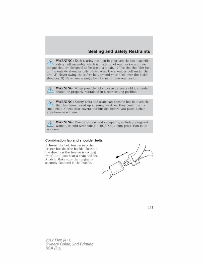
WARNING: Each seating position in your vehicle has a specificsafety belt assembly which is made up of one buckle and one
tongue that are designed to be used as a pair. 1) Use the shoulder belton the outside shoulder only. Never wear the shoulder belt under thearm. 2) Never swing the safety belt around your neck over the insideshoulder. 3) Never use a single belt for more than one person.
WARNING: When possible, all children 12 years old and undershould be properly restrained in a rear seating position.
WARNING: Safety belts and seats can become hot in a vehiclethat has been closed up in sunny weather; they could burn a
small child. Check seat covers and buckles before you place a childanywhere near them.
WARNING: Front and rear seat occupants, including pregnantwomen, should wear safety belts for optimum protection in an
accident.
Combination lap and shoulder belts1. Insert the belt tongue into theproper buckle (the buckle closest tothe direction the tongue is comingfrom) until you hear a snap and feelit latch. Make sure the tongue issecurely fastened in the buckle.
Seating and Safety Restraints
171
2012 Flex (471)Owners Guide, 2nd PrintingUSA (fus)
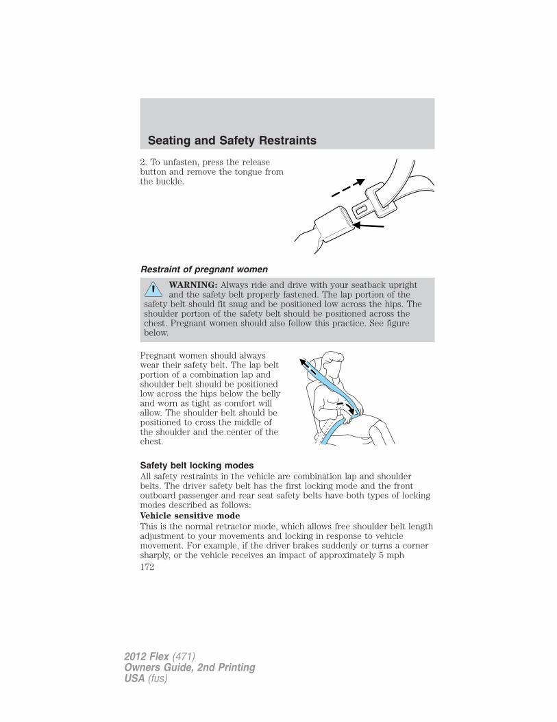
2. To unfasten, press the releasebutton and remove the tongue fromthe buckle.
Restraint of pregnant women
WARNING: Always ride and drive with your seatback uprightand the safety belt properly fastened. The lap portion of the
safety belt should fit snug and be positioned low across the hips. Theshoulder portion of the safety belt should be positioned across thechest. Pregnant women should also follow this practice. See figurebelow.
Pregnant women should alwayswear their safety belt. The lap beltportion of a combination lap andshoulder belt should be positionedlow across the hips below the bellyand worn as tight as comfort willallow. The shoulder belt should bepositioned to cross the middle ofthe shoulder and the center of thechest.
Safety belt locking modesAll safety restraints in the vehicle are combination lap and shoulderbelts. The driver safety belt has the first locking mode and the frontoutboard passenger and rear seat safety belts have both types of lockingmodes described as follows:Vehicle sensitive mode
This is the normal retractor mode, which allows free shoulder belt lengthadjustment to your movements and locking in response to vehiclemovement. For example, if the driver brakes suddenly or turns a cornersharply, or the vehicle receives an impact of approximately 5 mph
Seating and Safety Restraints
172
2012 Flex (471)Owners Guide, 2nd PrintingUSA (fus)
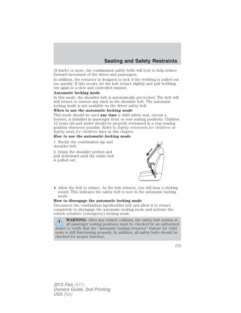
(8 km/h) or more, the combination safety belts will lock to help reduceforward movement of the driver and passengers.In addition, the retractor is designed to lock if the webbing is pulled outtoo quickly. If this occurs, let the belt retract slightly and pull webbingout again in a slow and controlled manner.Automatic locking mode
In this mode, the shoulder belt is automatically pre-locked. The belt willstill retract to remove any slack in the shoulder belt. The automaticlocking mode is not available on the driver safety belt.When to use the automatic locking mode
This mode should be used any time a child safety seat, except abooster, is installed in passenger front or rear seating positions. Children12 years old and under should be properly restrained in a rear seatingposition whenever possible. Refer to Safety restraints for children orSafety seats for children later in this chapter.How to use the automatic locking mode
1. Buckle the combination lap andshoulder belt.
2. Grasp the shoulder portion andpull downward until the entire beltis pulled out.
• Allow the belt to retract. As the belt retracts, you will hear a clickingsound. This indicates the safety belt is now in the automatic lockingmode.
How to disengage the automatic locking mode
Disconnect the combination lap/shoulder belt and allow it to retractcompletely to disengage the automatic locking mode and activate thevehicle sensitive (emergency) locking mode.
WARNING: After any vehicle collision, the safety belt system atall passenger seating positions must be checked by an authorized
dealer to verify that the “automatic locking retractor” feature for childseats is still functioning properly. In addition, all safety belts should bechecked for proper function.
Seating and Safety Restraints
173
2012 Flex (471)Owners Guide, 2nd PrintingUSA (fus)
WARNING: BELT AND RETRACTOR ASSEMBLY MUST BEREPLACED if the safety belt assembly “automatic locking
retractor” feature or any other safety belt function is not operatingproperly when checked by an authorized dealer. Failure to replace thebelt and retractor assembly could increase the risk of injury incollisions.
Energy management feature — front outboard• This vehicle has a safety belt system with an energy management
feature at the front seats to help further reduce the risk of injury inthe event of a head-on collision.
• The energy management feature has a retractor assembly that isdesigned to extend the safety belt webbing in a controlled manner.This helps reduce the belt force acting on the user’s chest.
WARNING: Failure to inspect and replace if necessary the beltand retractor assembly after an accident could increase the risk
of injury in a collision.
Safety belt pretensionerYour vehicle is equipped with safety belt pretensioners at the driver andfront outboard passenger seating positions.
The safety belt pretensioner tightens the safety belts firmly against theoccupant’s body at the start of the crash.
WARNING: The driver and front passenger safety belt system(including retractors, buckles and height adjusters) must be
replaced if the vehicle is involved in a collision that results indeployment of front airbags, seat-mounted side airbags and SafetyCanopy� System and safety belt pretensioners.
Seating and Safety Restraints
174
2012 Flex (471)Owners Guide, 2nd PrintingUSA (fus)
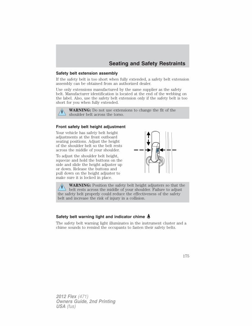
Safety belt extension assemblyIf the safety belt is too short when fully extended, a safety belt extensionassembly can be obtained from an authorized dealer.
Use only extensions manufactured by the same supplier as the safetybelt. Manufacturer identification is located at the end of the webbing onthe label. Also, use the safety belt extension only if the safety belt is tooshort for you when fully extended.
WARNING: Do not use extensions to change the fit of theshoulder belt across the torso.
Front safety belt height adjustmentYour vehicle has safety belt heightadjustments at the front outboardseating positions. Adjust the heightof the shoulder belt so the belt restsacross the middle of your shoulder.
To adjust the shoulder belt height,squeeze and hold the buttons on theside and slide the height adjuster upor down. Release the buttons andpull down on the height adjuster tomake sure it is locked in place.
WARNING: Position the safety belt height adjusters so that thebelt rests across the middle of your shoulder. Failure to adjust
the safety belt properly could reduce the effectiveness of the safetybelt and increase the risk of injury in a collision.
Safety belt warning light and indicator chime
The safety belt warning light illuminates in the instrument cluster and achime sounds to remind the occupants to fasten their safety belts.
Seating and Safety Restraints
175
2012 Flex (471)Owners Guide, 2nd PrintingUSA (fus)
Conditions of operation
If... Then...
The driver’s safety belt is notbuckled before the ignitionswitch is turned to the onposition...
The safety belt warning lightilluminates 1-2 minutes and thewarning chime sounds 4-8 seconds.
The driver’s safety belt isbuckled while the indicatorlight is illuminated and thewarning chime is sounding...
The safety belt warning light andwarning chime turn off.
The driver’s safety belt isbuckled before the ignitionswitch is turned to the onposition...
The safety belt warning light andindicator chime remain off.
Belt-Minder�
The Belt-Minder� feature is a supplemental warning to the safety beltwarning function. This feature provides additional reminders byintermittently sounding a chime and illuminating the safety belt warninglight in the instrument cluster when the driver’s and front passenger’ssafety belt is unbuckled.
The Belt-Minder� feature uses information from the front passengersensing system to determine if a front seat passenger is present andtherefore potentially in need of a warning. To avoid activating theBelt-Minder� feature for objects placed in the front passenger seat,warnings will only be given to large front seat occupants as determinedby the front passenger sensing system.
Both the driver’s and passenger’s safety belt usages are monitored andeither may activate the Belt-Minder� feature. The warnings are the samefor the driver and the front passenger. If the Belt-Minder� warnings haveexpired (warnings for approximately five minutes) for one occupant(driver or front passenger), the other occupant can still activate theBelt-Minder� feature.
Note: If you are using MyKey�, the Belt-Minder� warning will notexpire. Refer to MyKey� in the Locks and Security chapter.
Seating and Safety Restraints
176
2012 Flex (471)Owners Guide, 2nd PrintingUSA (fus)
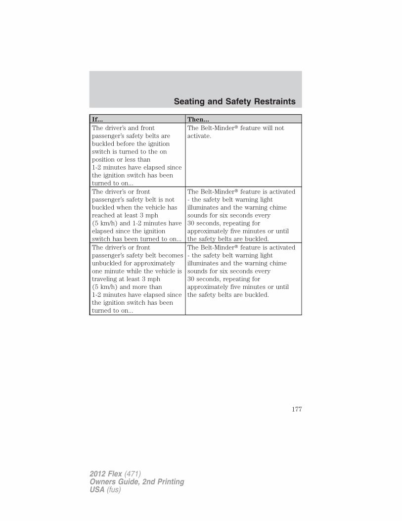
If... Then...
The driver’s and frontpassenger’s safety belts arebuckled before the ignitionswitch is turned to the onposition or less than1-2 minutes have elapsed sincethe ignition switch has beenturned to on...
The Belt-Minder� feature will notactivate.
The driver’s or frontpassenger’s safety belt is notbuckled when the vehicle hasreached at least 3 mph(5 km/h) and 1-2 minutes haveelapsed since the ignitionswitch has been turned to on...
The Belt-Minder� feature is activated- the safety belt warning lightilluminates and the warning chimesounds for six seconds every30 seconds, repeating forapproximately five minutes or untilthe safety belts are buckled.
The driver’s or frontpassenger’s safety belt becomesunbuckled for approximatelyone minute while the vehicle istraveling at least 3 mph(5 km/h) and more than1-2 minutes have elapsed sincethe ignition switch has beenturned to on...
The Belt-Minder� feature is activated- the safety belt warning lightilluminates and the warning chimesounds for six seconds every30 seconds, repeating forapproximately five minutes or untilthe safety belts are buckled.
Seating and Safety Restraints
177
2012 Flex (471)Owners Guide, 2nd PrintingUSA (fus)
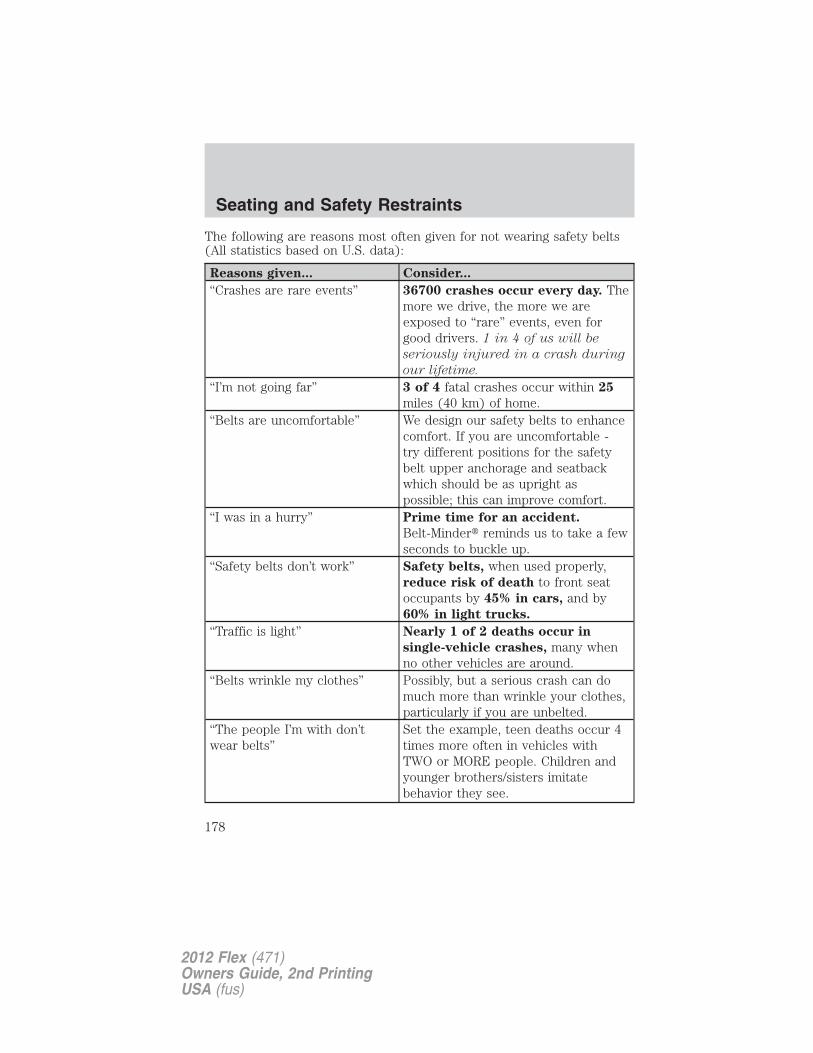
The following are reasons most often given for not wearing safety belts(All statistics based on U.S. data):
Reasons given... Consider...
“Crashes are rare events” 36700 crashes occur every day. Themore we drive, the more we areexposed to “rare” events, even forgood drivers. 1 in 4 of us will be
seriously injured in a crash during
our lifetime.
“I’m not going far” 3 of 4 fatal crashes occur within 25
miles (40 km) of home.“Belts are uncomfortable” We design our safety belts to enhance
comfort. If you are uncomfortable -try different positions for the safetybelt upper anchorage and seatbackwhich should be as upright aspossible; this can improve comfort.
“I was in a hurry” Prime time for an accident.
Belt-Minder� reminds us to take a fewseconds to buckle up.
“Safety belts don’t work” Safety belts, when used properly,reduce risk of death to front seatoccupants by 45% in cars, and by60% in light trucks.
“Traffic is light” Nearly 1 of 2 deaths occur in
single-vehicle crashes, many whenno other vehicles are around.
“Belts wrinkle my clothes” Possibly, but a serious crash can domuch more than wrinkle your clothes,particularly if you are unbelted.
“The people I’m with don’twear belts”
Set the example, teen deaths occur 4times more often in vehicles withTWO or MORE people. Children andyounger brothers/sisters imitatebehavior they see.
Seating and Safety Restraints
178
2012 Flex (471)Owners Guide, 2nd PrintingUSA (fus)
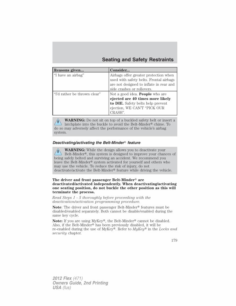
Reasons given... Consider...
“I have an airbag” Airbags offer greater protection whenused with safety belts. Frontal airbagsare not designed to inflate in rear andside crashes or rollovers.
“I’d rather be thrown clear” Not a good idea. People who areejected are 40 times more likely
to DIE. Safety belts help preventejection, WE CAN’T “PICK OURCRASH”.
WARNING: Do not sit on top of a buckled safety belt or insert alatchplate into the buckle to avoid the Belt-Minder� chime. To
do so may adversely affect the performance of the vehicle’s airbagsystem.
Deactivating/activating the Belt-Minder� feature
WARNING: While the design allows you to deactivate yourBelt-Minder�, this system is designed to improve your chances of
being safely belted and surviving an accident. We recommend youleave the Belt-Minder� system activated for yourself and others whomay use the vehicle. To reduce the risk of injury, do notdeactivate/activate the Belt-Minder� feature while driving the vehicle.
The driver and front passenger Belt-Minder� aredeactivated/activated independently. When deactivating/activatingone seating position, do not buckle the other position as this willterminate the process.
Read Steps 1 - 5 thoroughly before proceeding with thedeactivation/activation programming procedure.
Note: The driver and front passenger Belt-Minder� features must bedisabled/enabled separately. Both cannot be disable/enabled during thesame key cycle.
Note: If you are using MyKey�, the Belt-Minder� cannot be disabled.Also, if the Belt-Minder� has been previously disabled, it will bere-enabled during the use of MyKey�. Refer to MyKey� in the Locks andsecurity chapter.
Seating and Safety Restraints
179
2012 Flex (471)Owners Guide, 2nd PrintingUSA (fus)
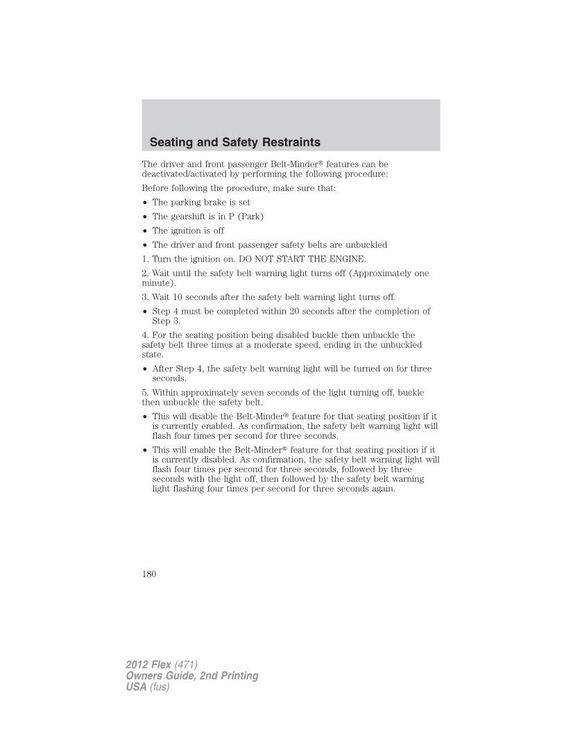
The driver and front passenger Belt-Minder� features can bedeactivated/activated by performing the following procedure:
Before following the procedure, make sure that:
• The parking brake is set
• The gearshift is in P (Park)
• The ignition is off
• The driver and front passenger safety belts are unbuckled
1. Turn the ignition on. DO NOT START THE ENGINE.
2. Wait until the safety belt warning light turns off (Approximately oneminute).
3. Wait 10 seconds after the safety belt warning light turns off.
• Step 4 must be completed within 20 seconds after the completion ofStep 3.
4. For the seating position being disabled buckle then unbuckle thesafety belt three times at a moderate speed, ending in the unbuckledstate.
• After Step 4, the safety belt warning light will be turned on for threeseconds.
5. Within approximately seven seconds of the light turning off, bucklethen unbuckle the safety belt.
• This will disable the Belt-Minder� feature for that seating position if itis currently enabled. As confirmation, the safety belt warning light willflash four times per second for three seconds.
• This will enable the Belt-Minder� feature for that seating position if itis currently disabled. As confirmation, the safety belt warning light willflash four times per second for three seconds, followed by threeseconds with the light off, then followed by the safety belt warninglight flashing four times per second for three seconds again.
Seating and Safety Restraints
180
2012 Flex (471)Owners Guide, 2nd PrintingUSA (fus)
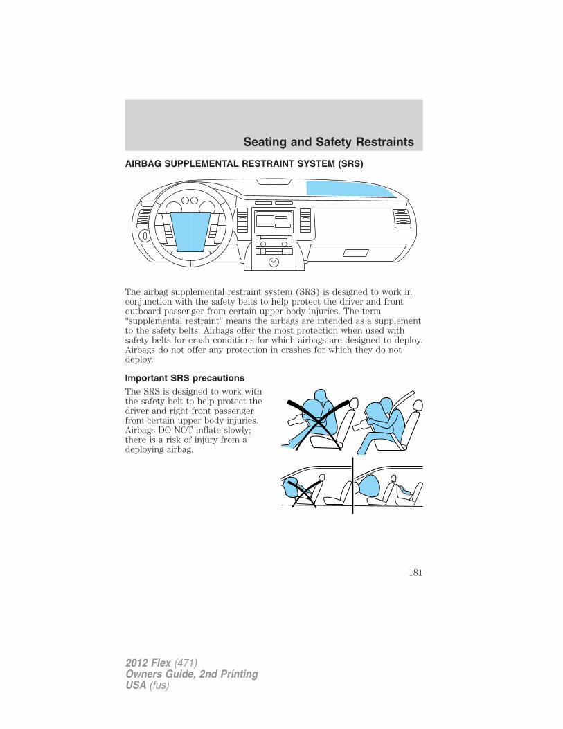
AIRBAG SUPPLEMENTAL RESTRAINT SYSTEM (SRS)
The airbag supplemental restraint system (SRS) is designed to work inconjunction with the safety belts to help protect the driver and frontoutboard passenger from certain upper body injuries. The term“supplemental restraint” means the airbags are intended as a supplementto the safety belts. Airbags offer the most protection when used withsafety belts for crash conditions for which airbags are designed to deploy.Airbags do not offer any protection in crashes for which they do notdeploy.
Important SRS precautionsThe SRS is designed to work withthe safety belt to help protect thedriver and right front passengerfrom certain upper body injuries.Airbags DO NOT inflate slowly;there is a risk of injury from adeploying airbag.
Seating and Safety Restraints
181
2012 Flex (471)Owners Guide, 2nd PrintingUSA (fus)
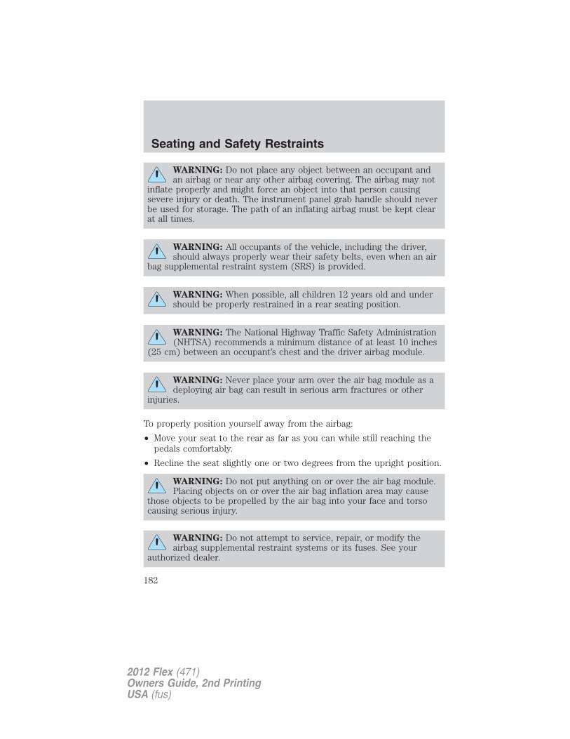
WARNING: Do not place any object between an occupant andan airbag or near any other airbag covering. The airbag may not
inflate properly and might force an object into that person causingsevere injury or death. The instrument panel grab handle should neverbe used for storage. The path of an inflating airbag must be kept clearat all times.
WARNING: All occupants of the vehicle, including the driver,should always properly wear their safety belts, even when an air
bag supplemental restraint system (SRS) is provided.
WARNING: When possible, all children 12 years old and undershould be properly restrained in a rear seating position.
WARNING: The National Highway Traffic Safety Administration(NHTSA) recommends a minimum distance of at least 10 inches
(25 cm) between an occupant’s chest and the driver airbag module.
WARNING: Never place your arm over the air bag module as adeploying air bag can result in serious arm fractures or other
injuries.
To properly position yourself away from the airbag:
• Move your seat to the rear as far as you can while still reaching thepedals comfortably.
• Recline the seat slightly one or two degrees from the upright position.
WARNING: Do not put anything on or over the air bag module.Placing objects on or over the air bag inflation area may cause
those objects to be propelled by the air bag into your face and torsocausing serious injury.
WARNING: Do not attempt to service, repair, or modify theairbag supplemental restraint systems or its fuses. See your
authorized dealer.
Seating and Safety Restraints
182
2012 Flex (471)Owners Guide, 2nd PrintingUSA (fus)
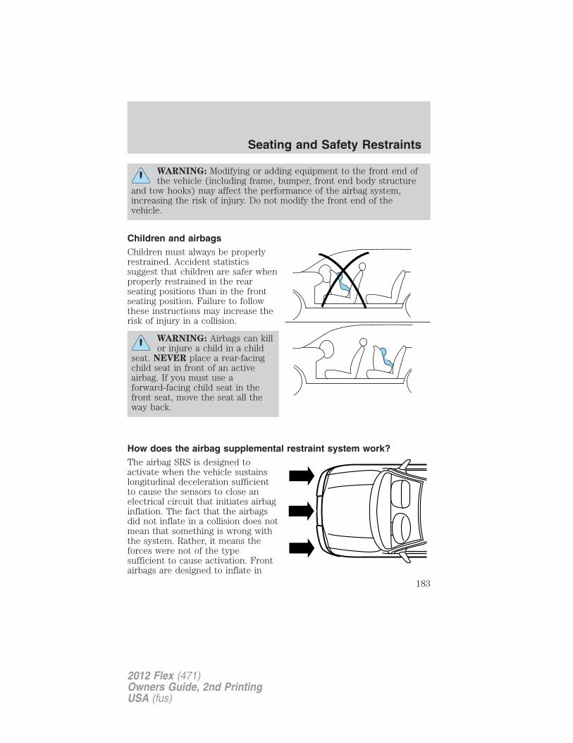
WARNING: Modifying or adding equipment to the front end ofthe vehicle (including frame, bumper, front end body structure
and tow hooks) may affect the performance of the airbag system,increasing the risk of injury. Do not modify the front end of thevehicle.
Children and airbagsChildren must always be properlyrestrained. Accident statisticssuggest that children are safer whenproperly restrained in the rearseating positions than in the frontseating position. Failure to followthese instructions may increase therisk of injury in a collision.
WARNING: Airbags can killor injure a child in a child
seat. NEVER place a rear-facingchild seat in front of an activeairbag. If you must use aforward-facing child seat in thefront seat, move the seat all theway back.
How does the airbag supplemental restraint system work?The airbag SRS is designed toactivate when the vehicle sustainslongitudinal deceleration sufficientto cause the sensors to close anelectrical circuit that initiates airbaginflation. The fact that the airbagsdid not inflate in a collision does notmean that something is wrong withthe system. Rather, it means theforces were not of the typesufficient to cause activation. Frontairbags are designed to inflate in
Seating and Safety Restraints
183
2012 Flex (471)Owners Guide, 2nd PrintingUSA (fus)
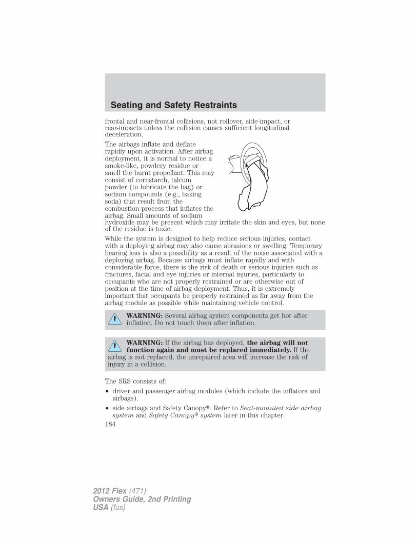
frontal and near-frontal collisions, not rollover, side-impact, orrear-impacts unless the collision causes sufficient longitudinaldeceleration.
The airbags inflate and deflaterapidly upon activation. After airbagdeployment, it is normal to notice asmoke-like, powdery residue orsmell the burnt propellant. This mayconsist of cornstarch, talcumpowder (to lubricate the bag) orsodium compounds (e.g., bakingsoda) that result from thecombustion process that inflates theairbag. Small amounts of sodiumhydroxide may be present which may irritate the skin and eyes, but noneof the residue is toxic.
While the system is designed to help reduce serious injuries, contactwith a deploying airbag may also cause abrasions or swelling. Temporaryhearing loss is also a possibility as a result of the noise associated with adeploying airbag. Because airbags must inflate rapidly and withconsiderable force, there is the risk of death or serious injuries such asfractures, facial and eye injuries or internal injuries, particularly tooccupants who are not properly restrained or are otherwise out ofposition at the time of airbag deployment. Thus, it is extremelyimportant that occupants be properly restrained as far away from theairbag module as possible while maintaining vehicle control.
WARNING: Several airbag system components get hot afterinflation. Do not touch them after inflation.
WARNING: If the airbag has deployed, the airbag will notfunction again and must be replaced immediately. If the
airbag is not replaced, the unrepaired area will increase the risk ofinjury in a collision.
The SRS consists of:
• driver and passenger airbag modules (which include the inflators andairbags).
• side airbags and Safety Canopy�. Refer to Seat-mounted side airbagsystem and Safety Canopy� system later in this chapter.
Seating and Safety Restraints
184
2012 Flex (471)Owners Guide, 2nd PrintingUSA (fus)
• one or more impact and safing sensors.• driver and front passenger safety belt pretensioner• a readiness light and tone.• diagnostic module.• the electrical wiring which connects the components.• Front passenger sensing system. Refer to Front passenger sensing
system later in this chapter.• “Passenger airbag off” or “pass airbag off” indicator lamp. Refer to
Front passenger sensing system later in this chapter.The diagnostic module monitors its own internal circuits and thesupplemental airbag electrical system wiring (including the impactsensors), the system wiring, the airbag system readiness light, the airbagback-up power and the airbag ignitors.
Front passenger sensing systemThe front passenger sensing system is designed to meet the regulatoryrequirements of Federal Motor Vehicle Safety Standard (FMVSS) 208and is designed to disable (will not inflate) the front passenger’s frontalairbag under certain conditions.
The front passenger sensing system works with sensors that are part ofthe front passenger’s seat and safety belt. The sensors are designed todetect the presence of a properly seated occupant and determine if thefront passenger’s frontal airbag should be enabled (may inflate) ordisabled (will not inflate).
The front passenger sensing system will disable (will not inflate) thefront passenger’s frontal airbag if:
• the front passenger seat is unoccupied, or has small/medium objects inthe front seat,
• the system determines that an infant is present in a rear-facing infantseat that is installed according to the manufacturer’s instructions,
• the system determines that a small child is present in a forward-facingchild restraint that is installed according to the manufacturer’sinstructions,
• the system determines that a small child is present in a booster seat,
• a front passenger takes his/her weight off of the seat for a period oftime,
• a child or a small person occupies the front passenger seat.
Seating and Safety Restraints
185
2012 Flex (471)Owners Guide, 2nd PrintingUSA (fus)
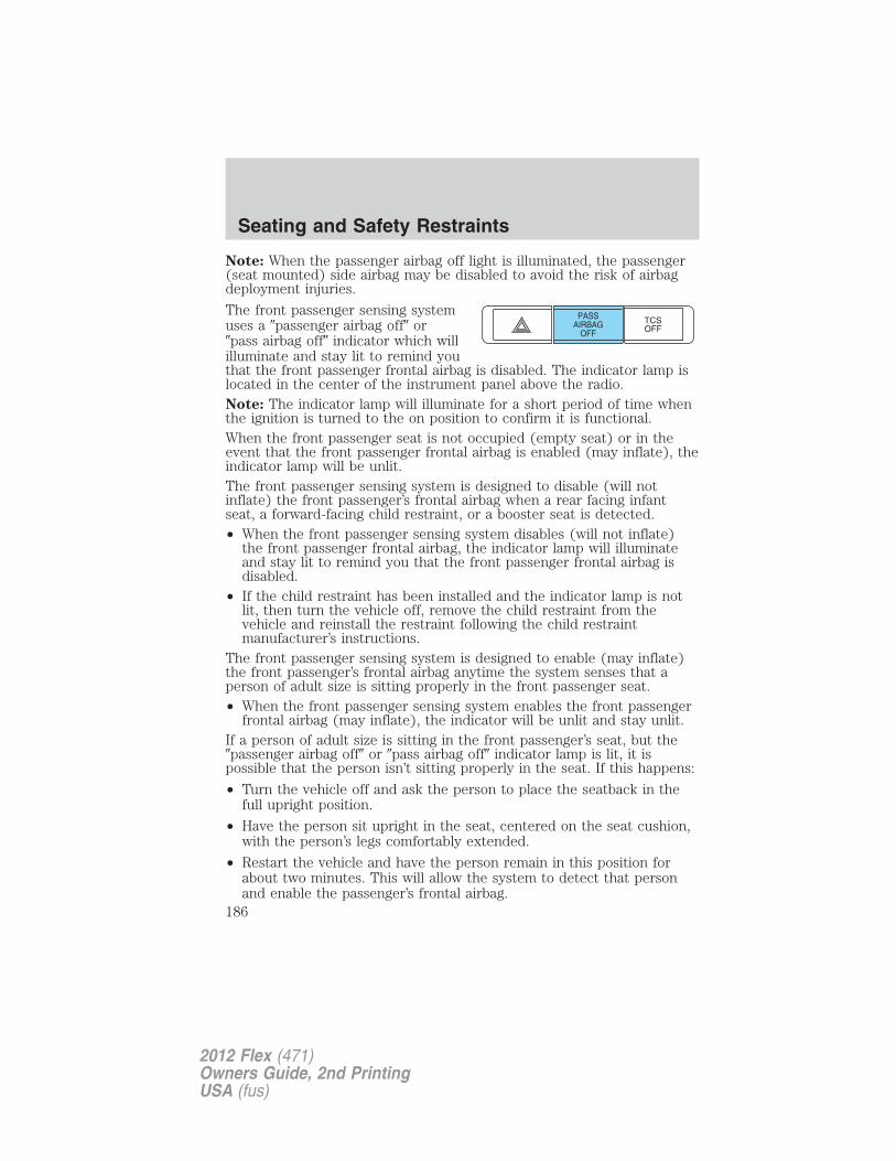
Note: When the passenger airbag off light is illuminated, the passenger(seat mounted) side airbag may be disabled to avoid the risk of airbagdeployment injuries.
The front passenger sensing systemuses a �passenger airbag off� or�pass airbag off� indicator which willilluminate and stay lit to remind youthat the front passenger frontal airbag is disabled. The indicator lamp islocated in the center of the instrument panel above the radio.Note: The indicator lamp will illuminate for a short period of time whenthe ignition is turned to the on position to confirm it is functional.When the front passenger seat is not occupied (empty seat) or in theevent that the front passenger frontal airbag is enabled (may inflate), theindicator lamp will be unlit.The front passenger sensing system is designed to disable (will notinflate) the front passenger’s frontal airbag when a rear facing infantseat, a forward-facing child restraint, or a booster seat is detected.• When the front passenger sensing system disables (will not inflate)
the front passenger frontal airbag, the indicator lamp will illuminateand stay lit to remind you that the front passenger frontal airbag isdisabled.
• If the child restraint has been installed and the indicator lamp is notlit, then turn the vehicle off, remove the child restraint from thevehicle and reinstall the restraint following the child restraintmanufacturer’s instructions.
The front passenger sensing system is designed to enable (may inflate)the front passenger’s frontal airbag anytime the system senses that aperson of adult size is sitting properly in the front passenger seat.• When the front passenger sensing system enables the front passenger
frontal airbag (may inflate), the indicator will be unlit and stay unlit.If a person of adult size is sitting in the front passenger’s seat, but the�passenger airbag off� or �pass airbag off� indicator lamp is lit, it ispossible that the person isn’t sitting properly in the seat. If this happens:
• Turn the vehicle off and ask the person to place the seatback in thefull upright position.
• Have the person sit upright in the seat, centered on the seat cushion,with the person’s legs comfortably extended.
• Restart the vehicle and have the person remain in this position forabout two minutes. This will allow the system to detect that personand enable the passenger’s frontal airbag.
Seating and Safety Restraints
186
2012 Flex (471)Owners Guide, 2nd PrintingUSA (fus)
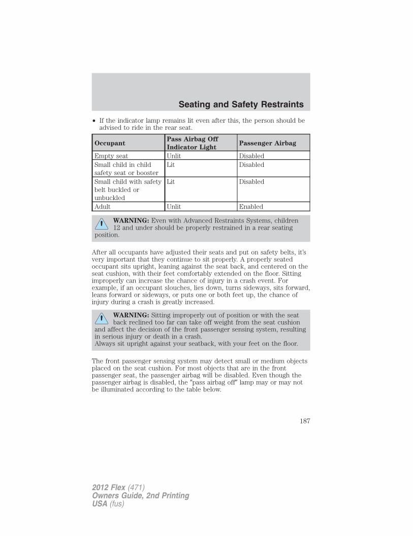
• If the indicator lamp remains lit even after this, the person should beadvised to ride in the rear seat.
OccupantPass Airbag Off
Indicator LightPassenger Airbag
Empty seat Unlit DisabledSmall child in childsafety seat or booster
Lit Disabled
Small child with safetybelt buckled orunbuckled
Lit Disabled
Adult Unlit Enabled
WARNING: Even with Advanced Restraints Systems, children12 and under should be properly restrained in a rear seating
position.
After all occupants have adjusted their seats and put on safety belts, it’svery important that they continue to sit properly. A properly seatedoccupant sits upright, leaning against the seat back, and centered on theseat cushion, with their feet comfortably extended on the floor. Sittingimproperly can increase the chance of injury in a crash event. Forexample, if an occupant slouches, lies down, turns sideways, sits forward,leans forward or sideways, or puts one or both feet up, the chance ofinjury during a crash is greatly increased.
WARNING: Sitting improperly out of position or with the seatback reclined too far can take off weight from the seat cushion
and affect the decision of the front passenger sensing system, resultingin serious injury or death in a crash.Always sit upright against your seatback, with your feet on the floor.
The front passenger sensing system may detect small or medium objectsplaced on the seat cushion. For most objects that are in the frontpassenger seat, the passenger airbag will be disabled. Even though thepassenger airbag is disabled, the �pass airbag off� lamp may or may notbe illuminated according to the table below.
Seating and Safety Restraints
187
2012 Flex (471)Owners Guide, 2nd PrintingUSA (fus)
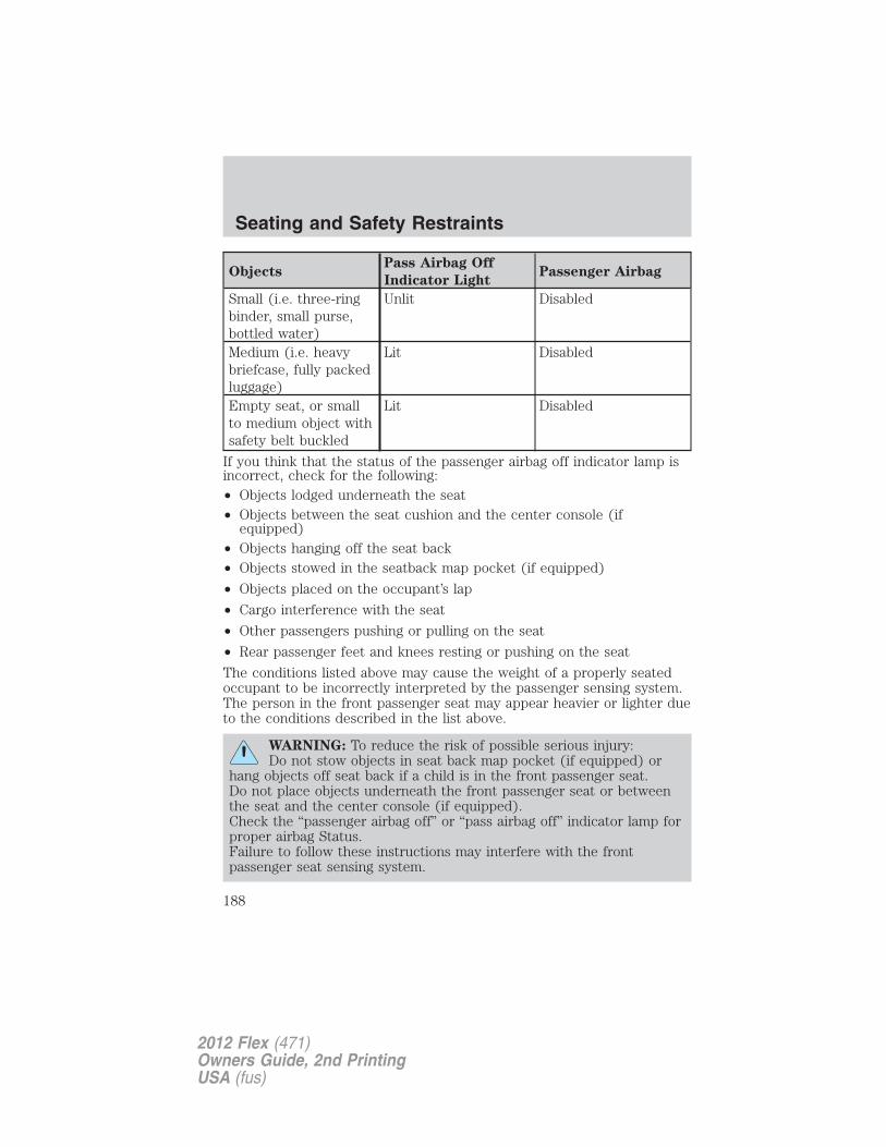
ObjectsPass Airbag Off
Indicator LightPassenger Airbag
Small (i.e. three-ringbinder, small purse,bottled water)
Unlit Disabled
Medium (i.e. heavybriefcase, fully packedluggage)
Lit Disabled
Empty seat, or smallto medium object withsafety belt buckled
Lit Disabled
If you think that the status of the passenger airbag off indicator lamp isincorrect, check for the following:• Objects lodged underneath the seat• Objects between the seat cushion and the center console (if
equipped)• Objects hanging off the seat back• Objects stowed in the seatback map pocket (if equipped)
• Objects placed on the occupant’s lap
• Cargo interference with the seat
• Other passengers pushing or pulling on the seat
• Rear passenger feet and knees resting or pushing on the seat
The conditions listed above may cause the weight of a properly seatedoccupant to be incorrectly interpreted by the passenger sensing system.The person in the front passenger seat may appear heavier or lighter dueto the conditions described in the list above.
WARNING: To reduce the risk of possible serious injury:Do not stow objects in seat back map pocket (if equipped) or
hang objects off seat back if a child is in the front passenger seat.Do not place objects underneath the front passenger seat or betweenthe seat and the center console (if equipped).Check the “passenger airbag off” or “pass airbag off” indicator lamp forproper airbag Status.Failure to follow these instructions may interfere with the frontpassenger seat sensing system.
Seating and Safety Restraints
188
2012 Flex (471)Owners Guide, 2nd PrintingUSA (fus)
In case there is a problem with thefront passenger sensing system, theairbag readiness lamp in theinstrument cluster will stay lit.If the airbag readiness lamp is lit, do the following:
The driver and/or adult passengers should check for any objects thatmay be lodged underneath the front passenger seat or cargo interferingwith the seat.
If objects are lodged and/or cargo is interfering with the seat; please takethe following steps to remove the obstruction:
• Pull the vehicle over.
• Turn the vehicle off.
• Driver and/or adult passengers should check for any objects lodgedunderneath the front passenger seat or cargo interfering with the seat.
• Remove the obstruction(s) (if found).
• Restart the vehicle.
• Wait at least two minutes and verify that the airbag readiness lamp isno longer illuminated
• If the airbag readiness lamp remains illuminated, this may or may/notbe a problem due to the front passenger sensing system.
DO NOT attempt to repair or service the system; take your vehicleimmediately to an authorized dealer.
If it is necessary to modify an advanced front airbag system toaccommodate a person with disabilities, contact the Ford CustomerRelationship Center at the phone number shown in the CustomerAssistance chapter of this Owner’s Guide.
WARNING: Any alteration/modification to the front passengerseat may affect the performance of the front passenger sensing
system.
Determining if the system is operationalThe supplemental restraint system uses a warning indicator light in theinstrument cluster or a backup tone to indicate the condition of thesystem. Refer to the Warning lights and chimes section in theInstrument Cluster chapter. Routine maintenance of the airbag is notrequired.
Seating and Safety Restraints
189
2012 Flex (471)Owners Guide, 2nd PrintingUSA (fus)
A difficulty with the system is indicated by one or more of the following:
• The readiness light (same lightfor front and side airbag system)will either flash or stay lit.
• The readiness light will notilluminate immediately after ignition is turned on.
• A series of five beeps will be heard. The tone pattern will repeatperiodically until the problem and/or light are repaired.
If any of these things happen, even intermittently, have the supplementalrestraint system serviced at an authorized dealer immediately. Unlessserviced, the system may not function properly in the event of acollision.
Seat-mounted side airbag system
WARNING: Do not place objects or mount equipment on ornear the airbag cover on the side of the seatbacks of the front
seats or in front seat areas that may come into contact with adeploying airbag. Failure to follow these instructions may increase therisk of personal injury in the event of a collision.
WARNING: Do not use accessory seat covers. The use ofaccessory seat covers may prevent the deployment of the side
airbags and increase the risk of injury in an accident.
WARNING: Do not lean your head on the door. The side airbagcould injure you as it deploys from the side of the seatback.
WARNING: Do not attempt to service, repair, or modify theairbag SRS, its fuses or the seat cover on a seat containing an
airbag. Contact your authorized dealer as soon as possible.
WARNING: All occupants of the vehicle should always weartheir safety belts even when an airbag SRS is provided.
How does the side airbag system work?The design and development of the side airbag system includedrecommended testing procedures that were developed by a group of
Seating and Safety Restraints
190
2012 Flex (471)Owners Guide, 2nd PrintingUSA (fus)
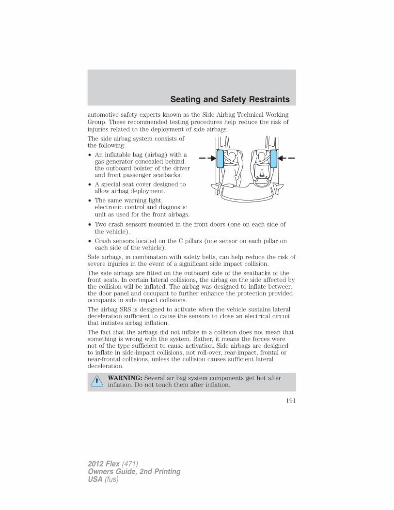
automotive safety experts known as the Side Airbag Technical WorkingGroup. These recommended testing procedures help reduce the risk ofinjuries related to the deployment of side airbags.
The side airbag system consists ofthe following:
• An inflatable bag (airbag) with agas generator concealed behindthe outboard bolster of the driverand front passenger seatbacks.
• A special seat cover designed toallow airbag deployment.
• The same warning light,electronic control and diagnosticunit as used for the front airbags.
• Two crash sensors mounted in the front doors (one on each side ofthe vehicle).
• Crash sensors located on the C pillars (one sensor on each pillar oneach side of the vehicle).
Side airbags, in combination with safety belts, can help reduce the risk ofsevere injuries in the event of a significant side impact collision.
The side airbags are fitted on the outboard side of the seatbacks of thefront seats. In certain lateral collisions, the airbag on the side affected bythe collision will be inflated. The airbag was designed to inflate betweenthe door panel and occupant to further enhance the protection providedoccupants in side impact collisions.
The airbag SRS is designed to activate when the vehicle sustains lateraldeceleration sufficient to cause the sensors to close an electrical circuitthat initiates airbag inflation.
The fact that the airbags did not inflate in a collision does not mean thatsomething is wrong with the system. Rather, it means the forces werenot of the type sufficient to cause activation. Side airbags are designedto inflate in side-impact collisions, not roll-over, rear-impact, frontal ornear-frontal collisions, unless the collision causes sufficient lateraldeceleration.
WARNING: Several air bag system components get hot afterinflation. Do not touch them after inflation.
Seating and Safety Restraints
191
2012 Flex (471)Owners Guide, 2nd PrintingUSA (fus)
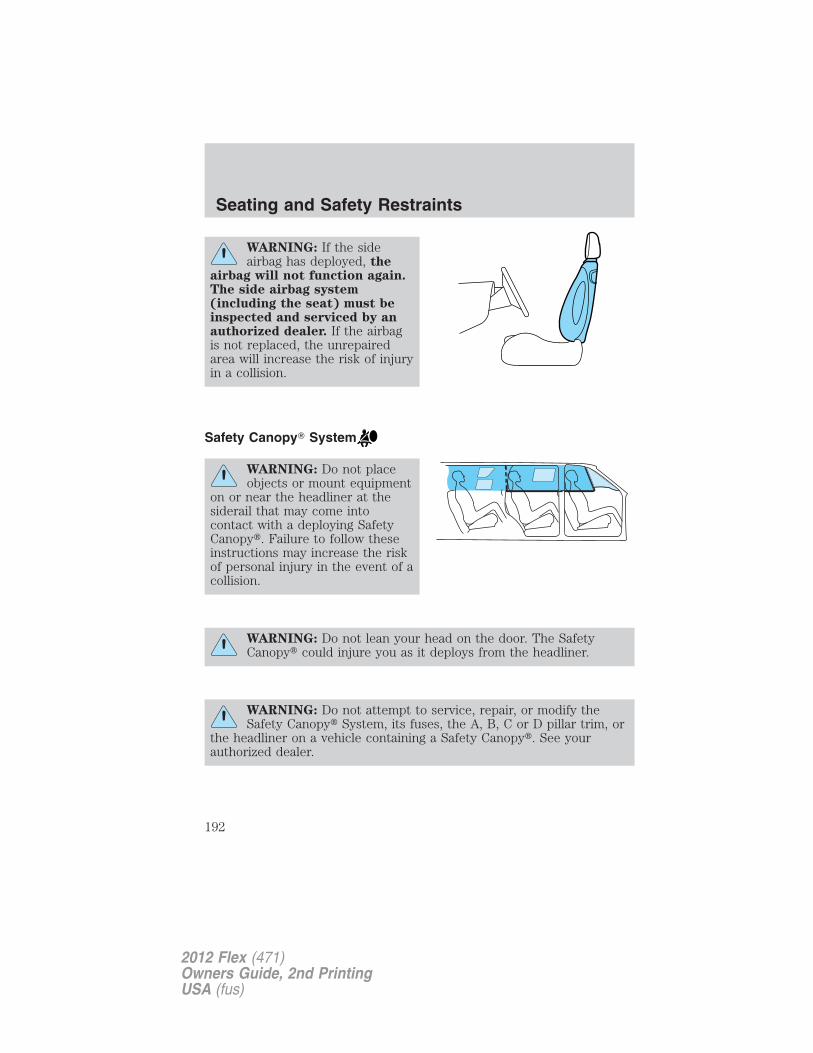
WARNING: If the sideairbag has deployed, the
airbag will not function again.The side airbag system(including the seat) must beinspected and serviced by anauthorized dealer. If the airbagis not replaced, the unrepairedarea will increase the risk of injuryin a collision.
Safety Canopy� System
WARNING: Do not placeobjects or mount equipment
on or near the headliner at thesiderail that may come intocontact with a deploying SafetyCanopy�. Failure to follow theseinstructions may increase the riskof personal injury in the event of acollision.
WARNING: Do not lean your head on the door. The SafetyCanopy� could injure you as it deploys from the headliner.
WARNING: Do not attempt to service, repair, or modify theSafety Canopy� System, its fuses, the A, B, C or D pillar trim, or
the headliner on a vehicle containing a Safety Canopy�. See yourauthorized dealer.
Seating and Safety Restraints
192
2012 Flex (471)Owners Guide, 2nd PrintingUSA (fus)
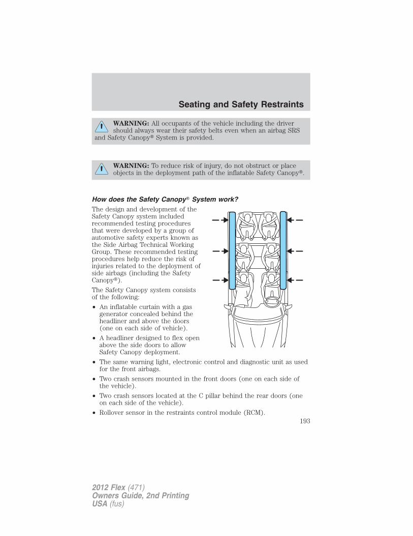
WARNING: All occupants of the vehicle including the drivershould always wear their safety belts even when an airbag SRS
and Safety Canopy� System is provided.
WARNING: To reduce risk of injury, do not obstruct or placeobjects in the deployment path of the inflatable Safety Canopy�.
How does the Safety Canopy� System work?The design and development of theSafety Canopy system includedrecommended testing proceduresthat were developed by a group ofautomotive safety experts known asthe Side Airbag Technical WorkingGroup. These recommended testingprocedures help reduce the risk ofinjuries related to the deployment ofside airbags (including the SafetyCanopy�).
The Safety Canopy system consistsof the following:
• An inflatable curtain with a gasgenerator concealed behind theheadliner and above the doors(one on each side of vehicle).
• A headliner designed to flex openabove the side doors to allowSafety Canopy deployment.
• The same warning light, electronic control and diagnostic unit as usedfor the front airbags.
• Two crash sensors mounted in the front doors (one on each side ofthe vehicle).
• Two crash sensors located at the C pillar behind the rear doors (oneon each side of the vehicle).
• Rollover sensor in the restraints control module (RCM).
Seating and Safety Restraints
193
2012 Flex (471)Owners Guide, 2nd PrintingUSA (fus)
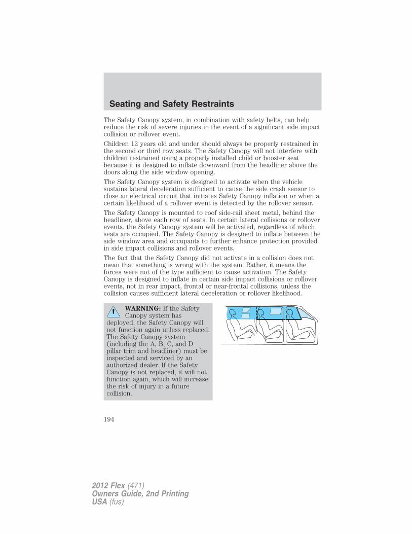
The Safety Canopy system, in combination with safety belts, can helpreduce the risk of severe injuries in the event of a significant side impactcollision or rollover event.
Children 12 years old and under should always be properly restrained inthe second or third row seats. The Safety Canopy will not interfere withchildren restrained using a properly installed child or booster seatbecause it is designed to inflate downward from the headliner above thedoors along the side window opening.
The Safety Canopy system is designed to activate when the vehiclesustains lateral deceleration sufficient to cause the side crash sensor toclose an electrical circuit that initiates Safety Canopy inflation or when acertain likelihood of a rollover event is detected by the rollover sensor.
The Safety Canopy is mounted to roof side-rail sheet metal, behind theheadliner, above each row of seats. In certain lateral collisions or rolloverevents, the Safety Canopy system will be activated, regardless of whichseats are occupied. The Safety Canopy is designed to inflate between theside window area and occupants to further enhance protection providedin side impact collisions and rollover events.
The fact that the Safety Canopy did not activate in a collision does notmean that something is wrong with the system. Rather, it means theforces were not of the type sufficient to cause activation. The SafetyCanopy is designed to inflate in certain side impact collisions or rolloverevents, not in rear impact, frontal or near-frontal collisions, unless thecollision causes sufficient lateral deceleration or rollover likelihood.
WARNING: If the SafetyCanopy system has
deployed, the Safety Canopy willnot function again unless replaced.The Safety Canopy system(including the A, B, C, and Dpillar trim and headliner) must beinspected and serviced by anauthorized dealer. If the SafetyCanopy is not replaced, it will notfunction again, which will increasethe risk of injury in a futurecollision.
Seating and Safety Restraints
194
2012 Flex (471)Owners Guide, 2nd PrintingUSA (fus)
Determining if the system is operational
The SRS uses a readiness light in the instrument cluster or a tone toindicate the condition of the system. Refer to Warning lights and
chimes in the Instrument Cluster chapter. Routine maintenance of theairbag is not required.
Any difficulty with the system is indicated by one or more of thefollowing:
• The readiness light (same light as for front airbag system) will eitherflash or stay lit.
• The readiness light will not illuminate immediately after ignition isturned on.
• A series of five beeps will be heard. The tone pattern will repeatperiodically until the problem and light are repaired.
If any of these things happen, even intermittently, have the SRS servicedat your authorized dealer immediately. Unless serviced, the system maynot function properly in the event of a collision or rollover event.
SOS Post-Crash Alert System™The system automatically flashes the turn signal lamps and sounds thehorn three times at four second intervals in the event of a serious impactthat deploys an airbag (front, side, side curtain [if equipped] or SafetyCanopy� [if equipped]) or the safety belt pretensioners.
The system can be turned off when any one of the following actions aretaken by the driver or any other person:
• pressing the hazard control button,
• or pressing the panic button on the remote entry transmitter.
The feature will continue to operate until the vehicle runs out of power.
Disposal of airbags and airbag equipped vehicles(including pretensioners)Contact your authorized dealer as soon as possible. Airbags MUST BEdisposed of by qualified personnel.
SAFETY RESTRAINTS FOR CHILDRENSee the following sections for directions on how to properly use safetyrestraints for children. Also see Airbag supplemental restraint system(SRS) in this chapter for special instructions about using airbags.
Seating and Safety Restraints
195
2012 Flex (471)Owners Guide, 2nd PrintingUSA (fus)
Important child restraint precautions
WARNING: Always make sure your child is secured properly ina device that is appropriate for their height, age and weight.
Child safety restraints must be purchased separately from the vehicle.Failure to follow these instructions and guidelines may result in anincreased risk of serious injury or death to your child.
WARNING: All children are shaped differently. TheRecommendations for Safety Restraints are based on probable
child height, age and weight thresholds from NHTSA and other safetyorganizations or are the minimum requirements of law. Fordrecommends checking with a NHTSA Certified Child Passenger SafetyTechnician (CPST) and consult your pediatrician to make sure yourchild seat is appropriate for your child, and is compatible with andproperly installed in the vehicle. To locate a child seat fitting stationand CPST contact the NHTSA toll free at 1-888-327-4236 or on theinternet at http://www.nhtsa.dot.gov. In Canada, check with your localSt. John Ambulance office for referral to a CPST or for furtherinformation, contact your provincial ministry of transportation, yourlocal St. John Ambulance office at http://www.sfa.ca, or TransportCanada at 1–800–333–0371 (http://www.tc.gc.ca). Failure to properlyrestrain children in safety seats made especially for their height, age,and weight may result in an increased risk of serious injury or death toyour child.
Seating and Safety Restraints
196
2012 Flex (471)Owners Guide, 2nd PrintingUSA (fus)
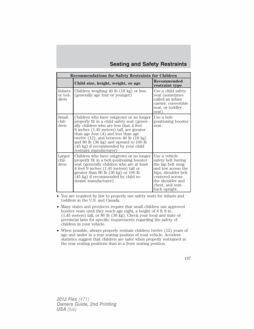
Recommendations for Safety Restraints for Children
Child size, height, weight, or ageRecommendedrestraint type
Infantsor tod-dlers
Children weighing 40 lb (18 kg) or less(generally age four or younger)
Use a child safetyseat (sometimescalled an infantcarrier, convertibleseat, or toddlerseat).
Smallchil-dren
Children who have outgrown or no longerproperly fit in a child safety seat (gener-ally children who are less than 4 feet9 inches (1.45 meters) tall, are greaterthan age four (4) and less than agetwelve (12), and between 40 lb (18 kg)and 80 lb (36 kg) and upward to 100 lb(45 kg) if recommended by your childrestraint manufacturer)
Use a belt-positioning boosterseat.
Largerchil-dren
Children who have outgrown or no longerproperly fit in a belt-positioning boosterseat (generally children who are at least4 feet 9 inches (1.45 meters) tall orgreater than 80 lb (36 kg) or 100 lb(45 kg) if recommended by child re-straint manufacturer)
Use a vehiclesafety belt havingthe lap belt snugand low across thehips, shoulder beltcentered acrossthe shoulder andchest, and seat-back upright.
• You are required by law to properly use safety seats for infants andtoddlers in the U.S. and Canada.
• Many states and provinces require that small children use approvedbooster seats until they reach age eight, a height of 4 ft 9 in.(1.45 meters) tall, or 80 lb (36 kg). Check your local and state orprovincial laws for specific requirements regarding the safety ofchildren in your vehicle.
• When possible, always properly restrain children twelve (12) years ofage and under in a rear seating position of your vehicle. Accidentstatistics suggest that children are safer when properly restrained inthe rear seating positions than in a front seating position.
Seating and Safety Restraints
197
2012 Flex (471)Owners Guide, 2nd PrintingUSA (fus)
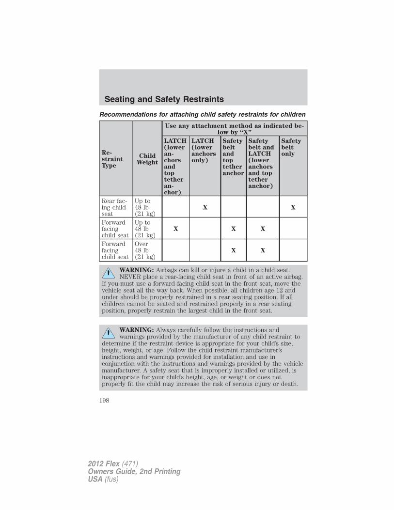
Recommendations for attaching child safety restraints for children
Re-straintType
ChildWeight
Use any attachment method as indicated be-low by “X”
LATCH(loweran-chorsandtoptetheran-chor)
LATCH(loweranchorsonly)
Safetybeltandtoptetheranchor
Safetybelt andLATCH(loweranchorsand toptetheranchor)
Safetybeltonly
Rear fac-ing childseat
Up to48 lb(21 kg)
X X
Forwardfacingchild seat
Up to48 lb(21 kg)
X X X
Forwardfacingchild seat
Over48 lb(21 kg)
X X
WARNING: Airbags can kill or injure a child in a child seat.NEVER place a rear-facing child seat in front of an active airbag.
If you must use a forward-facing child seat in the front seat, move thevehicle seat all the way back. When possible, all children age 12 andunder should be properly restrained in a rear seating position. If allchildren cannot be seated and restrained properly in a rear seatingposition, properly restrain the largest child in the front seat.
WARNING: Always carefully follow the instructions andwarnings provided by the manufacturer of any child restraint to
determine if the restraint device is appropriate for your child’s size,height, weight, or age. Follow the child restraint manufacturer’sinstructions and warnings provided for installation and use inconjunction with the instructions and warnings provided by the vehiclemanufacturer. A safety seat that is improperly installed or utilized, isinappropriate for your child’s height, age, or weight or does notproperly fit the child may increase the risk of serious injury or death.
Seating and Safety Restraints
198
2012 Flex (471)Owners Guide, 2nd PrintingUSA (fus)
WARNING: Never let a passenger hold a child on his or her lapwhile the vehicle is moving. The passenger cannot protect the
child from injury in a collision, which may result in serious injury ordeath.
WARNING: Never use pillows, books, or towels to boost a child.They can slide around and increase the likelihood of injury or
death in a collision.
WARNING: Always restrain an unoccupied child seat or boosterseat. These objects may become projectiles in a collision or
sudden stop, which may increase the risk of serious injury.
WARNING: Never place, or allow a child to place, the shoulderbelt under a child’s arm or behind the back because it reduces
the protection for the upper part of the body and may increase the riskof injury or death in a collision.
WARNING: Do not leave children, unreliable adults, or petsunattended in your vehicle.
Transporting childrenAlways make sure your child is secured properly in a device that isappropriate for their age, height and weight. All children are shapeddifferently. The child height, age and weight thresholds provided arerecommendations or the minimum requirements of law. The NationalHighway Traffic Safety Administration (NHTSA) provides education andtraining to ensure that all children ages 0 to 16 are properly restrained inthe correct restraint system. Ford recommends checking with a NHTSACertified Child Passenger Safety Technician (CPST) and yourpediatrician to make sure your seat is appropriate for your child andproperly installed in the vehicle. To locate a child seat fitting station andCPST contact the NHTSA toll free at 1-888-327-4236 or on the internetat http://www.nhtsa.dot.gov. In Canada, check with your local St. JohnAmbulance office for referral to a CPST or for further information,contact your provincial ministry of transportation, your local St. JohnAmbulance office at http://www.sfa.ca, or Transport Canada at1–800–333–0371 (http://www.tc.gc.ca).
Seating and Safety Restraints
199
2012 Flex (471)Owners Guide, 2nd PrintingUSA (fus)
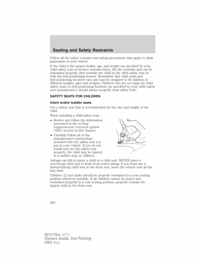
Follow all the safety restraint and airbag precautions that apply to adultpassengers in your vehicle.
If the child is the proper height, age, and weight (as specified by yourchild safety seat or booster manufacturer), fits the restraint and can berestrained properly, then restrain the child in the child safety seat orwith the belt-positioning booster. Remember that child seats andbelt-positioning boosters vary and may be designed to fit children ofdifferent heights, ages and weights. Children who are too large for childsafety seats or belt-positioning boosters (as specified by your child safetyseat manufacturer) should always properly wear safety belts.
SAFETY SEATS FOR CHILDREN
Infant and/or toddler seatsUse a safety seat that is recommended for the size and weight of thechild.
When installing a child safety seat:
• Review and follow the informationpresented in the Airbagsupplemental restraint system(SRS) section in this chapter.
• Carefully follow all of themanufacturer’s instructionsincluded with the safety seat youput in your vehicle. If you do notinstall and use the safety seatproperly, the child may be injuredin a sudden stop or collision.
Airbags can kill or injure a child in a child seat. NEVER place arear-facing child seat in front of an active airbag. If you must use aforward-facing child seat in the front seat, move the vehicle seat all theway back.
Children 12 and under should be properly restrained in a rear seatingposition whenever possible. If all children cannot be seated andrestrained properly in a rear seating position, properly restrain thelargest child in the front seat.
Seating and Safety Restraints
200
2012 Flex (471)Owners Guide, 2nd PrintingUSA (fus)
Installing child safety seats with combination lap and shoulderbelts
Check to make sure the child seat is properly secured before each use.Children 12 and under should be properly restrained in a rear seatingposition whenever possible. If all children cannot be seated andrestrained properly in a rear seating position, properly restrain thelargest child in the front seat.
When installing a child safety seat with combination lap/shoulder belts:
• Use the correct safety belt buckle for that seating position.
• Insert the belt tongue into the proper buckle until you hear a snapand feel it latch. Make sure the tongue is securely fastened in thebuckle.
• Keep the buckle release button pointing up and away from the safetyseat, with the tongue between the child seat and the release button,to help prevent accidental unbuckling.
• Place vehicle seat back in upright position.
• Put the safety belt in the automatic locking mode. Refer to Step 5below. This vehicle does not require the use of a locking clip.
WARNING: Depending on where you secure a child restraint,and depending on the child restraint design, you may block
access to certain safety belt buckle assemblies and/or LATCH loweranchors, rendering those features potentially unusable. To avoid risk ofinjury, occupants should only use seating positions where they are ableto be properly restrained.
Perform the following steps when installing the child seat withcombination lap/shoulder belts:
Note: Although the child seat illustrated is a forward facing child seat,the steps are the same for installing a rear facing child seat.
Seating and Safety Restraints
201
2012 Flex (471)Owners Guide, 2nd PrintingUSA (fus)
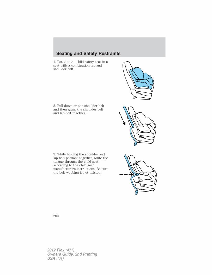
1. Position the child safety seat in aseat with a combination lap andshoulder belt.
2. Pull down on the shoulder beltand then grasp the shoulder beltand lap belt together.
3. While holding the shoulder andlap belt portions together, route thetongue through the child seataccording to the child seatmanufacturer’s instructions. Be surethe belt webbing is not twisted.
Seating and Safety Restraints
202
2012 Flex (471)Owners Guide, 2nd PrintingUSA (fus)
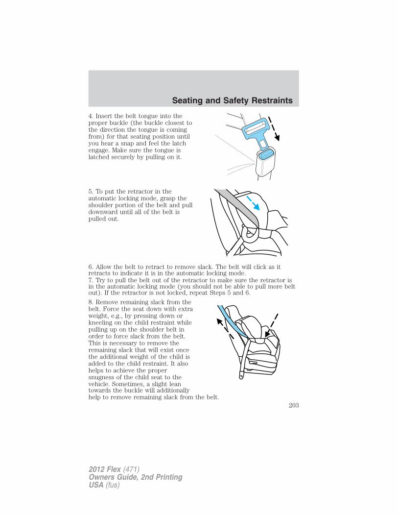
4. Insert the belt tongue into theproper buckle (the buckle closest tothe direction the tongue is comingfrom) for that seating position untilyou hear a snap and feel the latchengage. Make sure the tongue islatched securely by pulling on it.
5. To put the retractor in theautomatic locking mode, grasp theshoulder portion of the belt and pulldownward until all of the belt ispulled out.
6. Allow the belt to retract to remove slack. The belt will click as itretracts to indicate it is in the automatic locking mode.7. Try to pull the belt out of the retractor to make sure the retractor isin the automatic locking mode (you should not be able to pull more beltout). If the retractor is not locked, repeat Steps 5 and 6.
8. Remove remaining slack from thebelt. Force the seat down with extraweight, e.g., by pressing down orkneeling on the child restraint whilepulling up on the shoulder belt inorder to force slack from the belt.This is necessary to remove theremaining slack that will exist oncethe additional weight of the child isadded to the child restraint. It alsohelps to achieve the propersnugness of the child seat to thevehicle. Sometimes, a slight leantowards the buckle will additionallyhelp to remove remaining slack from the belt.
Seating and Safety Restraints
203
2012 Flex (471)Owners Guide, 2nd PrintingUSA (fus)
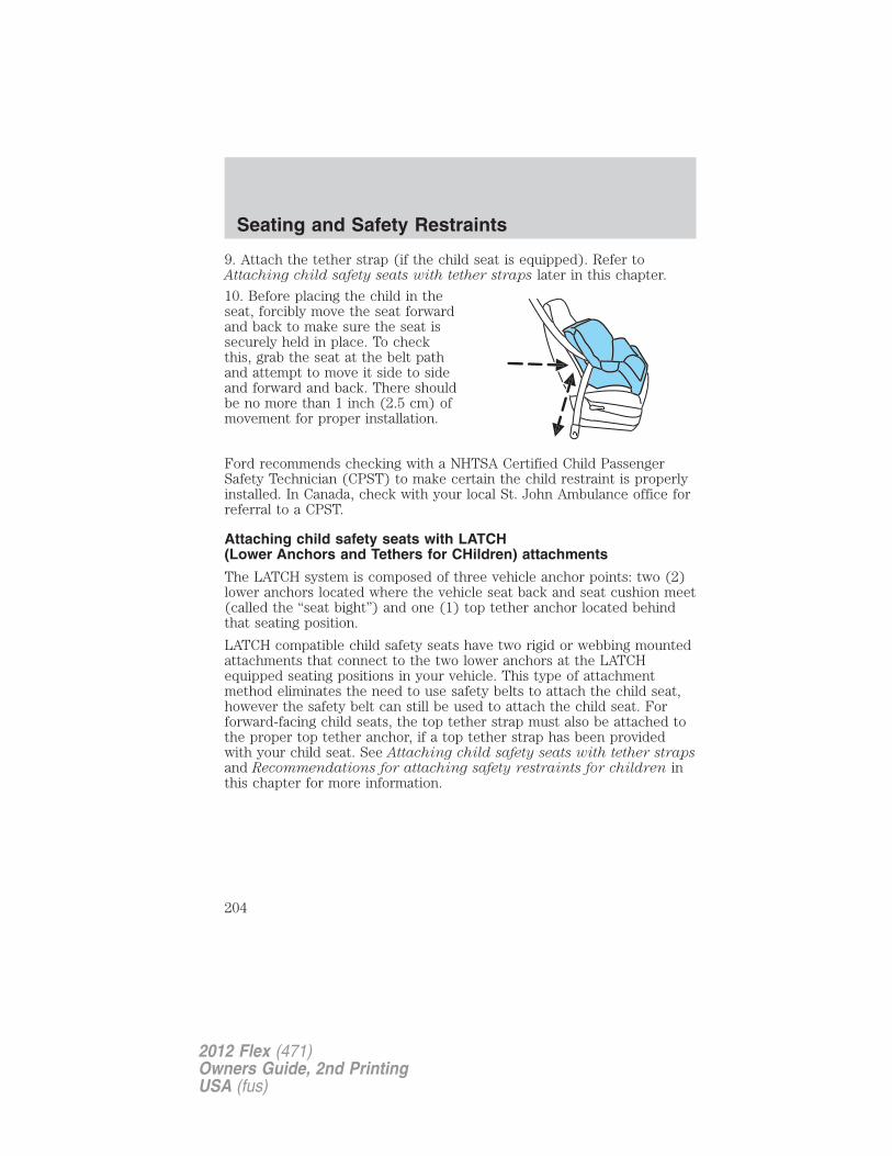
9. Attach the tether strap (if the child seat is equipped). Refer toAttaching child safety seats with tether straps later in this chapter.
10. Before placing the child in theseat, forcibly move the seat forwardand back to make sure the seat issecurely held in place. To checkthis, grab the seat at the belt pathand attempt to move it side to sideand forward and back. There shouldbe no more than 1 inch (2.5 cm) ofmovement for proper installation.
Ford recommends checking with a NHTSA Certified Child PassengerSafety Technician (CPST) to make certain the child restraint is properlyinstalled. In Canada, check with your local St. John Ambulance office forreferral to a CPST.
Attaching child safety seats with LATCH(Lower Anchors and Tethers for CHildren) attachments
The LATCH system is composed of three vehicle anchor points: two (2)lower anchors located where the vehicle seat back and seat cushion meet(called the “seat bight”) and one (1) top tether anchor located behindthat seating position.
LATCH compatible child safety seats have two rigid or webbing mountedattachments that connect to the two lower anchors at the LATCHequipped seating positions in your vehicle. This type of attachmentmethod eliminates the need to use safety belts to attach the child seat,however the safety belt can still be used to attach the child seat. Forforward-facing child seats, the top tether strap must also be attached tothe proper top tether anchor, if a top tether strap has been providedwith your child seat. See Attaching child safety seats with tether strapsand Recommendations for attaching safety restraints for children inthis chapter for more information.
Seating and Safety Restraints
204
2012 Flex (471)Owners Guide, 2nd PrintingUSA (fus)
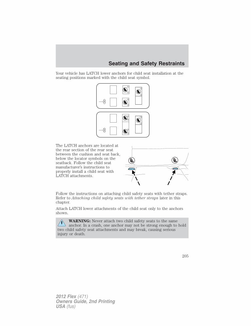
Your vehicle has LATCH lower anchors for child seat installation at theseating positions marked with the child seat symbol.
The LATCH anchors are located atthe rear section of the rear seatbetween the cushion and seat back,below the locator symbols on theseatback. Follow the child seatmanufacturer’s instructions toproperly install a child seat withLATCH attachments.
Follow the instructions on attaching child safety seats with tether straps.Refer to Attaching child safety seats with tether straps later in thischapter.
Attach LATCH lower attachments of the child seat only to the anchorsshown.
WARNING: Never attach two child safety seats to the sameanchor. In a crash, one anchor may not be strong enough to hold
two child safety seat attachments and may break, causing seriousinjury or death.
Seating and Safety Restraints
205
2012 Flex (471)Owners Guide, 2nd PrintingUSA (fus)
WARNING: Depending on where you secure a child restraint,and depending on the child restraint design, you may block
access to certain safety belt buckle assemblies and/or LATCH loweranchors, rendering those features potentially unusable. To avoid risk ofinjury, occupants should only use seating positions where they are ableto be properly restrained.
Use of inboard lower anchors from the outboard seating positions(center seating use)The lower anchors at the center of the second row rear seat are spaced520 mm (20.5 inches) apart. The standardized spacing for LATCH loweranchors is 280 mm (11 inches) center to center. A child seat with rigidLATCH attachments cannot be installed at the center seating position.LATCH compatible child seats (with attachments on belt webbing) canonly be used at this seating position provided that the child seatmanufacturer’s instructions permit use with the anchor spacing stated.Do not attach a child seat to any lower anchor if an adjacent child seat isattached to that anchor.
WARNING: The standardized spacing for LATCH lower anchorsis 280 mm (11 inches) center to center. Do not use LATCH
lower anchors for the center seating position unless the child seatmanufacturer’s instructions permit and specify using anchors spaced atleast as far apart as those in this vehicle.
Each time you use the safety seat, check that the seat is properlyattached to the lower anchors and tether anchor, if applicable. Tug thechild seat from side to side and forward and back where it is secured tothe vehicle. The seat should move less than one inch when you do thisfor a proper installation.
If the safety seat is not anchored properly, the risk of a child beinginjured in a crash greatly increases.
Combining safety belt and LATCH lower anchors for attachingchild safety seatsWhen used in combination, either the safety belt or the LATCH loweranchors may be attached first, provided a proper installation is achieved.Attach the tether strap afterward, if included with the child seat. Referto Recommendations for attaching child safety restraints for childrenin this chapter.
Seating and Safety Restraints
206
2012 Flex (471)Owners Guide, 2nd PrintingUSA (fus)
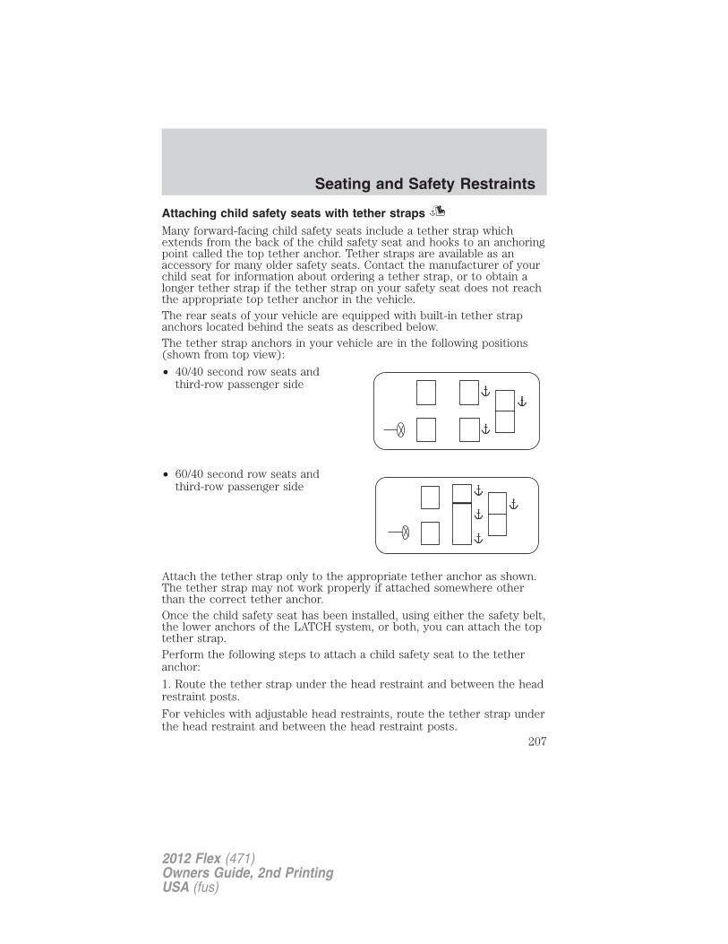
Attaching child safety seats with tether strapsMany forward-facing child safety seats include a tether strap whichextends from the back of the child safety seat and hooks to an anchoringpoint called the top tether anchor. Tether straps are available as anaccessory for many older safety seats. Contact the manufacturer of yourchild seat for information about ordering a tether strap, or to obtain alonger tether strap if the tether strap on your safety seat does not reachthe appropriate top tether anchor in the vehicle.The rear seats of your vehicle are equipped with built-in tether strapanchors located behind the seats as described below.The tether strap anchors in your vehicle are in the following positions(shown from top view):
• 40/40 second row seats andthird-row passenger side
• 60/40 second row seats andthird-row passenger side
Attach the tether strap only to the appropriate tether anchor as shown.The tether strap may not work properly if attached somewhere otherthan the correct tether anchor.Once the child safety seat has been installed, using either the safety belt,the lower anchors of the LATCH system, or both, you can attach the toptether strap.Perform the following steps to attach a child safety seat to the tetheranchor:
1. Route the tether strap under the head restraint and between the headrestraint posts.
For vehicles with adjustable head restraints, route the tether strap underthe head restraint and between the head restraint posts.
Seating and Safety Restraints
207
2012 Flex (471)Owners Guide, 2nd PrintingUSA (fus)
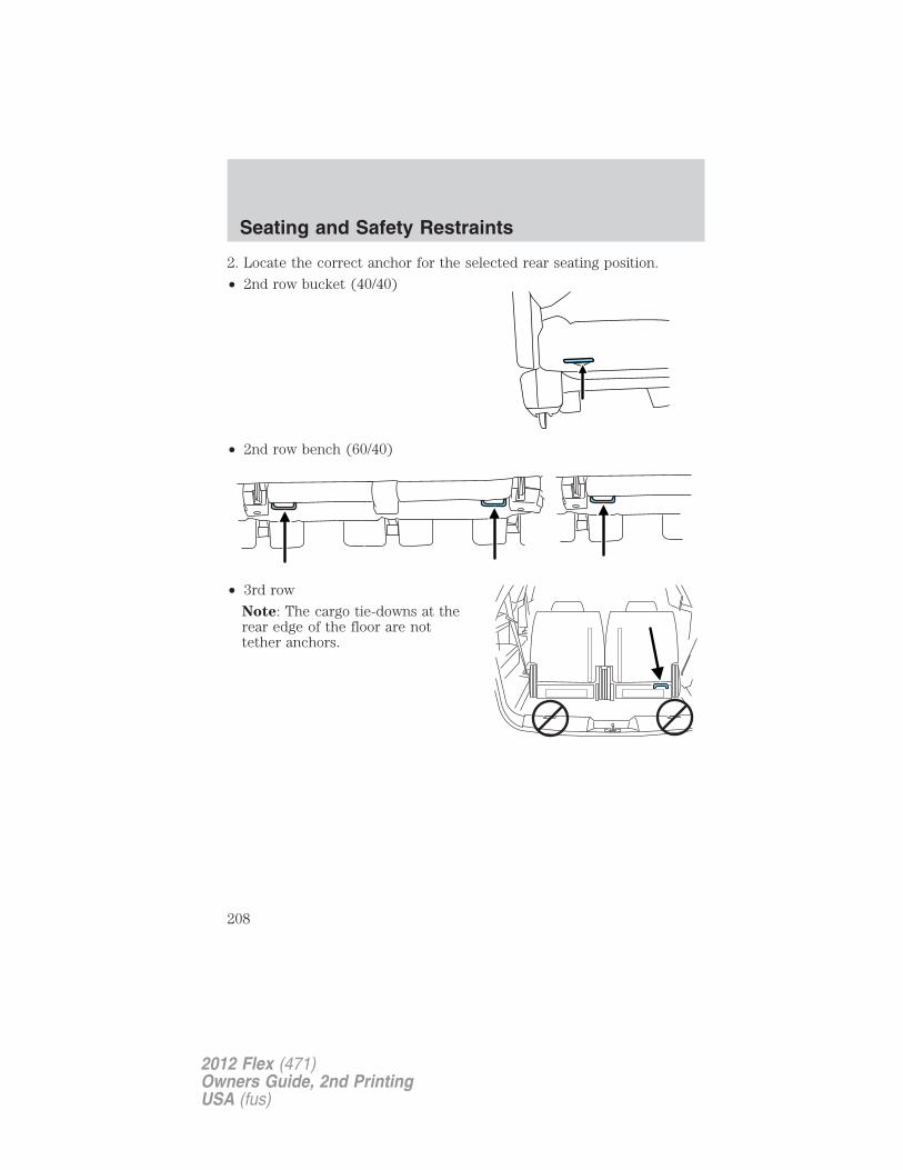
2. Locate the correct anchor for the selected rear seating position.
• 2nd row bucket (40/40)
• 2nd row bench (60/40)
• 3rd row
Note: The cargo tie-downs at therear edge of the floor are nottether anchors.
Seating and Safety Restraints
208
2012 Flex (471)Owners Guide, 2nd PrintingUSA (fus)
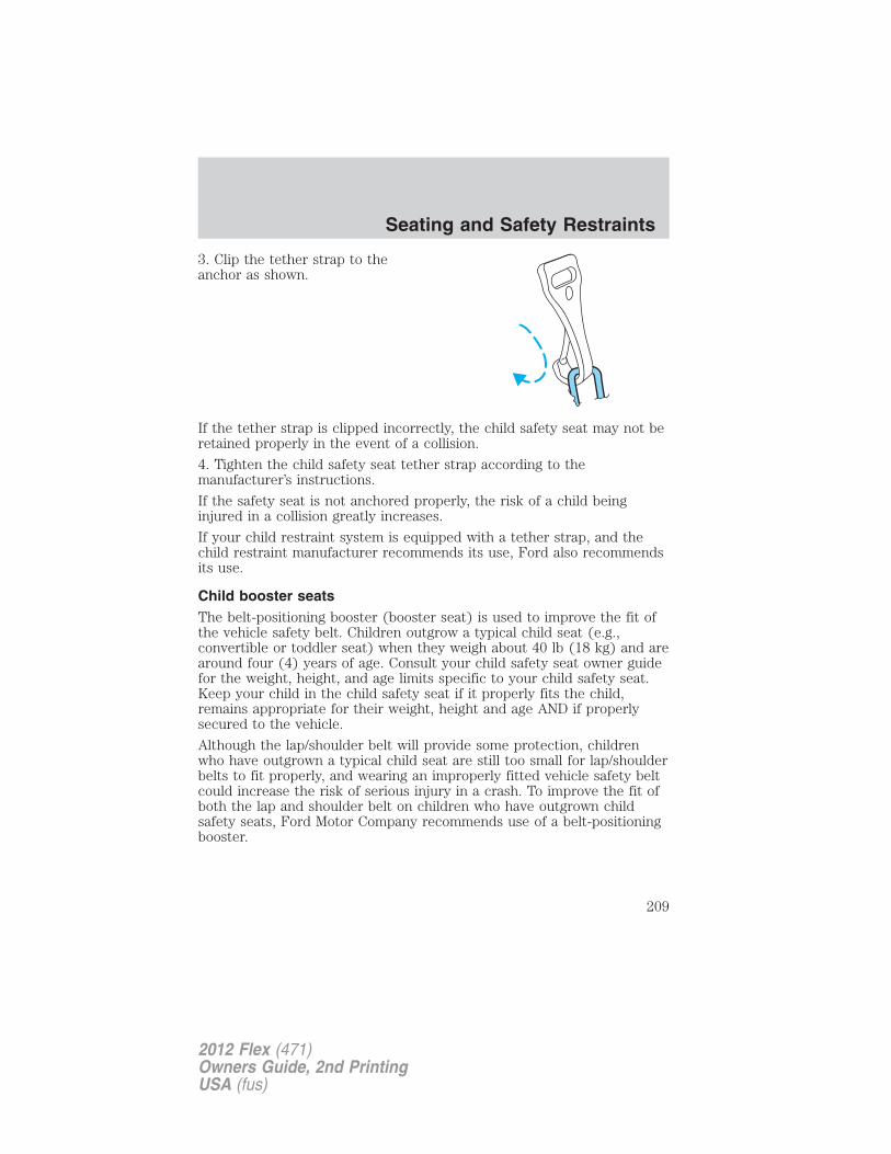
3. Clip the tether strap to theanchor as shown.
If the tether strap is clipped incorrectly, the child safety seat may not beretained properly in the event of a collision.
4. Tighten the child safety seat tether strap according to themanufacturer’s instructions.
If the safety seat is not anchored properly, the risk of a child beinginjured in a collision greatly increases.
If your child restraint system is equipped with a tether strap, and thechild restraint manufacturer recommends its use, Ford also recommendsits use.
Child booster seatsThe belt-positioning booster (booster seat) is used to improve the fit ofthe vehicle safety belt. Children outgrow a typical child seat (e.g.,convertible or toddler seat) when they weigh about 40 lb (18 kg) and arearound four (4) years of age. Consult your child safety seat owner guidefor the weight, height, and age limits specific to your child safety seat.Keep your child in the child safety seat if it properly fits the child,remains appropriate for their weight, height and age AND if properlysecured to the vehicle.
Although the lap/shoulder belt will provide some protection, childrenwho have outgrown a typical child seat are still too small for lap/shoulderbelts to fit properly, and wearing an improperly fitted vehicle safety beltcould increase the risk of serious injury in a crash. To improve the fit ofboth the lap and shoulder belt on children who have outgrown childsafety seats, Ford Motor Company recommends use of a belt-positioningbooster.
Seating and Safety Restraints
209
2012 Flex (471)Owners Guide, 2nd PrintingUSA (fus)
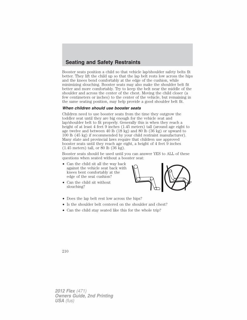
Booster seats position a child so that vehicle lap/shoulder safety belts fitbetter. They lift the child up so that the lap belt rests low across the hipsand the knees bend comfortably at the edge of the cushion, whileminimizing slouching. Booster seats may also make the shoulder belt fitbetter and more comfortably. Try to keep the belt near the middle of theshoulder and across the center of the chest. Moving the child closer (afew centimeters or inches) to the center of the vehicle, but remaining inthe same seating position, may help provide a good shoulder belt fit.
When children should use booster seatsChildren need to use booster seats from the time they outgrow thetoddler seat until they are big enough for the vehicle seat andlap/shoulder belt to fit properly. Generally this is when they reach aheight of at least 4 feet 9 inches (1.45 meters) tall (around age eight toage twelve and between 40 lb (18 kg) and 80 lb (36 kg) or upward to100 lb (45 kg) if recommended by your child restraint manufacturer).Many state and provincial laws require that children use approvedbooster seats until they reach age eight, a height of 4 feet 9 inches(1.45 meters) tall, or 80 lb (36 kg).
Booster seats should be used until you can answer YES to ALL of thesequestions when seated without a booster seat:
• Can the child sit all the way backagainst the vehicle seat back withknees bent comfortably at theedge of the seat cushion?
• Can the child sit withoutslouching?
• Does the lap belt rest low across the hips?
• Is the shoulder belt centered on the shoulder and chest?
• Can the child stay seated like this for the whole trip?
Seating and Safety Restraints
210
2012 Flex (471)Owners Guide, 2nd PrintingUSA (fus)
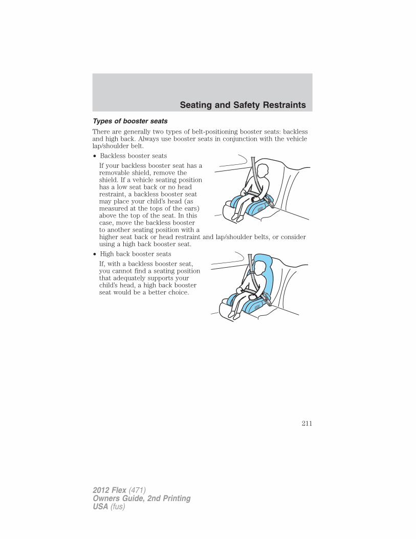
Types of booster seats
There are generally two types of belt-positioning booster seats: backlessand high back. Always use booster seats in conjunction with the vehiclelap/shoulder belt.
• Backless booster seats
If your backless booster seat has aremovable shield, remove theshield. If a vehicle seating positionhas a low seat back or no headrestraint, a backless booster seatmay place your child’s head (asmeasured at the tops of the ears)above the top of the seat. In thiscase, move the backless boosterto another seating position with ahigher seat back or head restraint and lap/shoulder belts, or considerusing a high back booster seat.
• High back booster seats
If, with a backless booster seat,you cannot find a seating positionthat adequately supports yourchild’s head, a high back boosterseat would be a better choice.
Seating and Safety Restraints
211
2012 Flex (471)Owners Guide, 2nd PrintingUSA (fus)
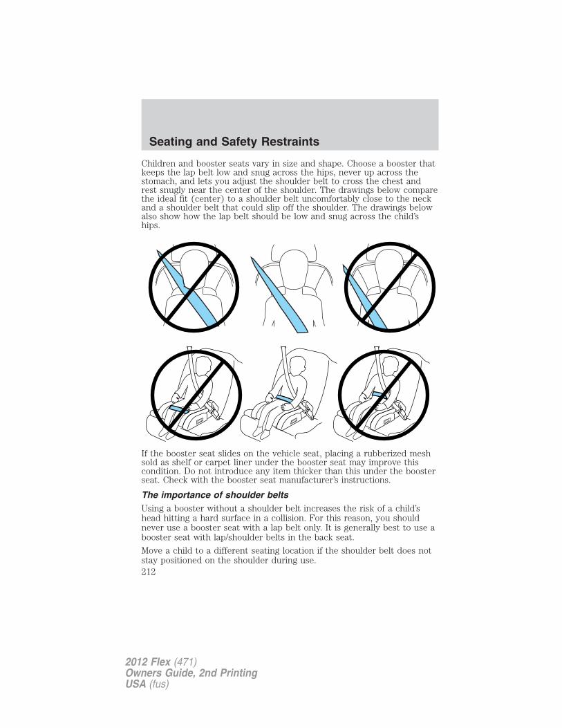
Children and booster seats vary in size and shape. Choose a booster thatkeeps the lap belt low and snug across the hips, never up across thestomach, and lets you adjust the shoulder belt to cross the chest andrest snugly near the center of the shoulder. The drawings below comparethe ideal fit (center) to a shoulder belt uncomfortably close to the neckand a shoulder belt that could slip off the shoulder. The drawings belowalso show how the lap belt should be low and snug across the child’ships.
If the booster seat slides on the vehicle seat, placing a rubberized meshsold as shelf or carpet liner under the booster seat may improve thiscondition. Do not introduce any item thicker than this under the boosterseat. Check with the booster seat manufacturer’s instructions.
The importance of shoulder beltsUsing a booster without a shoulder belt increases the risk of a child’shead hitting a hard surface in a collision. For this reason, you shouldnever use a booster seat with a lap belt only. It is generally best to use abooster seat with lap/shoulder belts in the back seat.
Move a child to a different seating location if the shoulder belt does notstay positioned on the shoulder during use.
Seating and Safety Restraints
212
2012 Flex (471)Owners Guide, 2nd PrintingUSA (fus)
Follow all instructions provided by the manufacturer of the booster seat.
WARNING: Never place, or allow a child to place, the shoulderbelt under a child’s arm or behind the back because it reduces
the protection for the upper part of the body and may increase the riskof injury or death in a collision.
Child restraint and safety belt maintenanceInspect the vehicle safety belts and child safety seat systems periodicallyto make sure they work properly and are not damaged. Inspect thevehicle and child seat safety belts to make sure there are no nicks, tearsor cuts. Replace if necessary. All vehicle safety belt assemblies, includingretractors, buckles, front safety belt buckle assemblies, buckle supportassemblies (slide bar-if equipped), shoulder belt height adjusters (ifequipped), shoulder belt guide on seatback (if equipped), child safetyseat LATCH and tether anchors, and attaching hardware, should beinspected after a collision. Refer to the child restraint manufacturer’sinstructions for additional inspection and maintenance informationspecific to the child restraint. Ford Motor Company recommends that allsafety belt assemblies in use in vehicles involved in a collision bereplaced. However, if the collision was minor and an authorized dealerfinds that the belts do not show damage and continue to operateproperly, they do not need to be replaced. Safety belt assemblies not inuse during a collision should also be inspected and replaced if eitherdamage or improper operation is noted.
For proper care of soiled safety belts, refer to Interior in the Cleaningchapter.
WARNING: Failure to inspect and if necessary replace thesafety belt assembly or child restraint system under the above
conditions could result in severe personal injuries in the event of acollision.
Seating and Safety Restraints
213
2012 Flex (471)Owners Guide, 2nd PrintingUSA (fus)
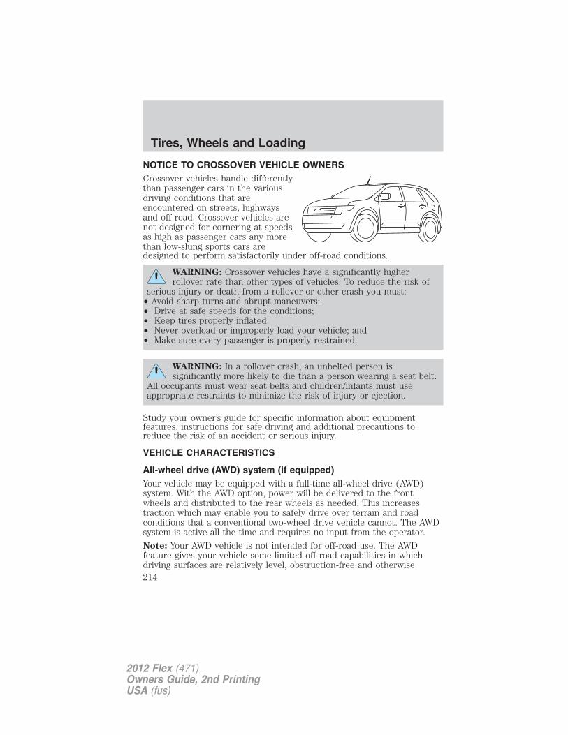
NOTICE TO CROSSOVER VEHICLE OWNERSCrossover vehicles handle differentlythan passenger cars in the variousdriving conditions that areencountered on streets, highwaysand off-road. Crossover vehicles arenot designed for cornering at speedsas high as passenger cars any morethan low-slung sports cars aredesigned to perform satisfactorily under off-road conditions.
WARNING: Crossover vehicles have a significantly higherrollover rate than other types of vehicles. To reduce the risk of
serious injury or death from a rollover or other crash you must:• Avoid sharp turns and abrupt maneuvers;• Drive at safe speeds for the conditions;• Keep tires properly inflated;• Never overload or improperly load your vehicle; and• Make sure every passenger is properly restrained.
WARNING: In a rollover crash, an unbelted person issignificantly more likely to die than a person wearing a seat belt.
All occupants must wear seat belts and children/infants must useappropriate restraints to minimize the risk of injury or ejection.
Study your owner’s guide for specific information about equipmentfeatures, instructions for safe driving and additional precautions toreduce the risk of an accident or serious injury.
VEHICLE CHARACTERISTICS
All-wheel drive (AWD) system (if equipped)Your vehicle may be equipped with a full-time all-wheel drive (AWD)system. With the AWD option, power will be delivered to the frontwheels and distributed to the rear wheels as needed. This increasestraction which may enable you to safely drive over terrain and roadconditions that a conventional two-wheel drive vehicle cannot. The AWDsystem is active all the time and requires no input from the operator.
Note: Your AWD vehicle is not intended for off-road use. The AWDfeature gives your vehicle some limited off-road capabilities in whichdriving surfaces are relatively level, obstruction-free and otherwise
Tires, Wheels and Loading
214
2012 Flex (471)Owners Guide, 2nd PrintingUSA (fus)
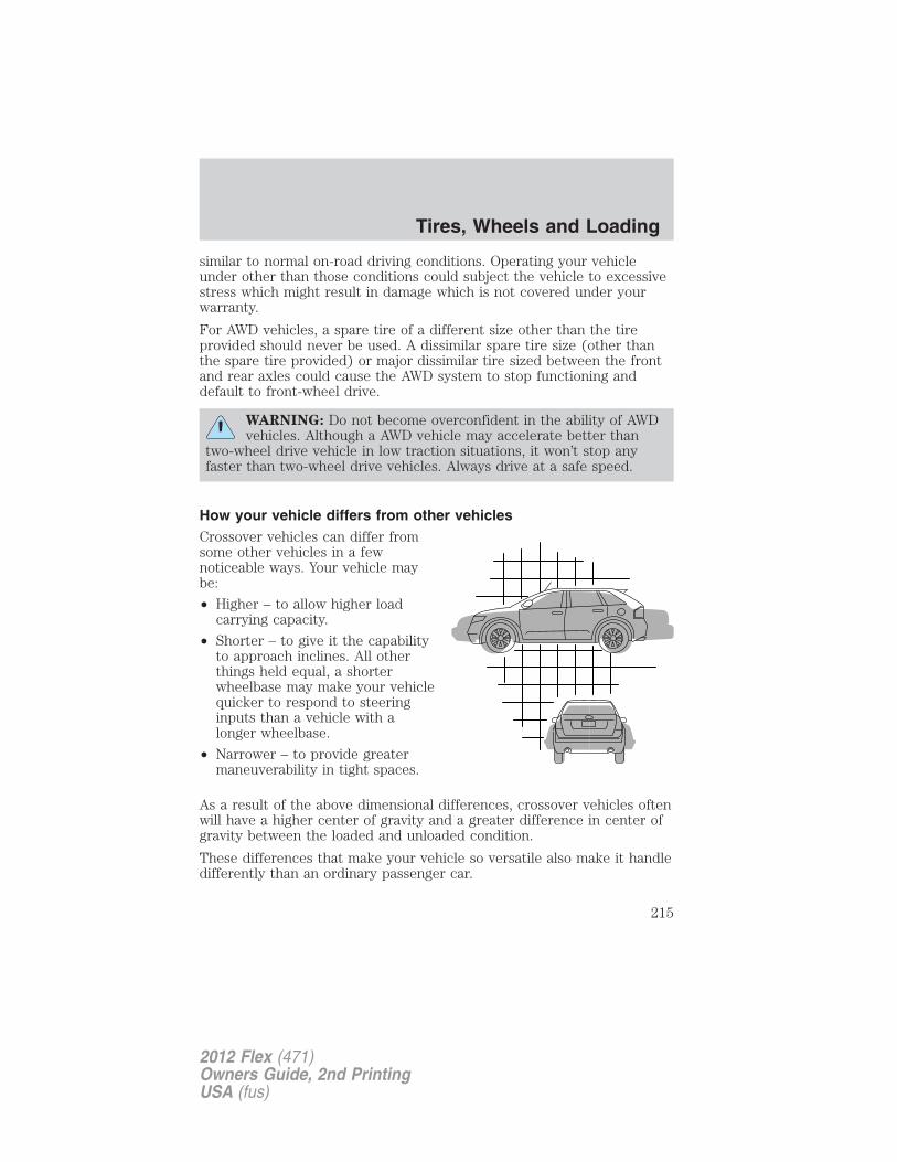
similar to normal on-road driving conditions. Operating your vehicleunder other than those conditions could subject the vehicle to excessivestress which might result in damage which is not covered under yourwarranty.
For AWD vehicles, a spare tire of a different size other than the tireprovided should never be used. A dissimilar spare tire size (other thanthe spare tire provided) or major dissimilar tire sized between the frontand rear axles could cause the AWD system to stop functioning anddefault to front-wheel drive.
WARNING: Do not become overconfident in the ability of AWDvehicles. Although a AWD vehicle may accelerate better than
two-wheel drive vehicle in low traction situations, it won’t stop anyfaster than two-wheel drive vehicles. Always drive at a safe speed.
How your vehicle differs from other vehiclesCrossover vehicles can differ fromsome other vehicles in a fewnoticeable ways. Your vehicle maybe:
• Higher – to allow higher loadcarrying capacity.
• Shorter – to give it the capabilityto approach inclines. All otherthings held equal, a shorterwheelbase may make your vehiclequicker to respond to steeringinputs than a vehicle with alonger wheelbase.
• Narrower – to provide greatermaneuverability in tight spaces.
As a result of the above dimensional differences, crossover vehicles oftenwill have a higher center of gravity and a greater difference in center ofgravity between the loaded and unloaded condition.
These differences that make your vehicle so versatile also make it handledifferently than an ordinary passenger car.
Tires, Wheels and Loading
215
2012 Flex (471)Owners Guide, 2nd PrintingUSA (fus)
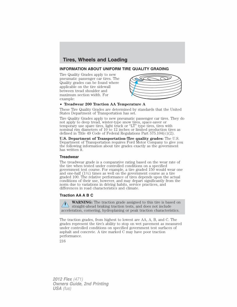
INFORMATION ABOUT UNIFORM TIRE QUALITY GRADINGTire Quality Grades apply to newpneumatic passenger car tires. TheQuality grades can be found whereapplicable on the tire sidewallbetween tread shoulder andmaximum section width. Forexample:• Treadwear 200 Traction AA Temperature A
These Tire Quality Grades are determined by standards that the UnitedStates Department of Transportation has set.Tire Quality Grades apply to new pneumatic passenger car tires. They donot apply to deep tread, winter-type snow tires, space-saver ortemporary use spare tires, light truck or “LT” type tires, tires withnominal rim diameters of 10 to 12 inches or limited production tires asdefined in Title 49 Code of Federal Regulations Part 575.104(c)(2).U.S. Department of Transportation-Tire quality grades: The U.S.Department of Transportation requires Ford Motor Company to give youthe following information about tire grades exactly as the governmenthas written it.
TreadwearThe treadwear grade is a comparative rating based on the wear rate ofthe tire when tested under controlled conditions on a specifiedgovernment test course. For example, a tire graded 150 would wear oneand one-half (11⁄2) times as well on the government course as a tiregraded 100. The relative performance of tires depends upon the actualconditions of their use, however, and may depart significantly from thenorm due to variations in driving habits, service practices, anddifferences in road characteristics and climate.
Traction AA A B C
WARNING: The traction grade assigned to this tire is based onstraight-ahead braking traction tests, and does not include
acceleration, cornering, hydroplaning or peak traction characteristics.
The traction grades, from highest to lowest are AA, A, B, and C. Thegrades represent the tire’s ability to stop on wet pavement as measuredunder controlled conditions on specified government test surfaces ofasphalt and concrete. A tire marked C may have poor tractionperformance.
Tires, Wheels and Loading
216
2012 Flex (471)Owners Guide, 2nd PrintingUSA (fus)
Temperature A B C
WARNING: The temperature grade for this tire is establishedfor a tire that is properly inflated and not overloaded. Excessive
speed, underinflation, or excessive loading, either separately or incombination, can cause heat buildup and possible tire failure.
The temperature grades are A (the highest), B and C, representing thetire’s resistance to the generation of heat and its ability to dissipate heatwhen tested under controlled conditions on a specified indoor laboratorytest wheel. Sustained high temperature can cause the material of the tireto degenerate and reduce tire life, and excessive temperature can lead tosudden tire failure. The grade C corresponds to a level of performancewhich all passenger car tires must meet under the Federal Motor VehicleSafety Standard No. 139. Grades B and A represent higher levels ofperformance on the laboratory test wheel than the minimum required bylaw.
TIRESTires are designed to give many thousands of miles of service, but theymust be maintained in order to get the maximum benefit from them.
Glossary of Tire Terminology• Tire label: A label showing the OE (Original Equipment) tire sizes,
recommended inflation pressure and the maximum weight the vehiclecan carry.
• Tire Identification Number (TIN): A number on the sidewall ofeach tire providing information about the tire brand andmanufacturing plant, tire size and date of manufacture. Also referredto as DOT code.
• Inflation pressure: A measure of the amount of air in a tire.
• Standard load: A class of P-metric or Metric tires designed to carry amaximum load at 35 psi [37 psi (2.5 bar) for Metric tires]. Increasingthe inflation pressure beyond this pressure will not increase the tire’sload carrying capability.
• Extra load: A class of P-metric or Metric tires designed to carry aheavier maximum load at 41 psi [43 psi (2.9 bar) for Metric tires].Increasing the inflation pressure beyond this pressure will not increasethe tire’s load carrying capability.
• kPa: Kilopascal, a metric unit of air pressure.
Tires, Wheels and Loading
217
2012 Flex (471)Owners Guide, 2nd PrintingUSA (fus)
• PSI: Pounds per square inch, a standard unit of air pressure.• Cold inflation pressure: The tire pressure when the vehicle has
been stationary and out of direct sunlight for an hour or more andprior to the vehicle being driven for 1 mile (1.6 km).
• Recommended inflation pressure: The cold inflation pressure foundon the Safety Compliance Certification Label or Tire Label located onthe B-Pillar or the edge of the driver’s door.
• B-pillar: The structural member at the side of the vehicle behind thefront door.
• Bead area of the tire: Area of the tire next to the rim.• Sidewall of the tire: Area between the bead area and the tread.• Tread area of the tire: Area of the perimeter of the tire that
contacts the road when mounted on the vehicle.• Rim: The metal support (wheel) for a tire or a tire and tube assembly
upon which the tire beads are seated.INFLATING YOUR TIRESSafe operation of your vehicle requires that your tires are properlyinflated. Remember that a tire can lose up to half of its air pressurewithout appearing flat.Every day before you drive, check your tires. If one looks lower than theothers, use a tire gauge to check pressure of all tires and adjust ifrequired.At least once a month and before long trips, inspect each tire and checkthe tire pressure with a tire gauge (including spare, if equipped). Inflateall tires to the inflation pressure recommended by Ford Motor Company.You are strongly urged to buy a reliable tire pressure gauge, as automaticservice station gauges may be inaccurate. Ford recommends the use of adigital or dial-type tire pressure gauge rather than a stick-type tirepressure gauge.Use the recommended cold inflation pressure for optimum tireperformance and wear. Under-inflation or over-inflation may causeuneven treadwear patterns.
WARNING: Under-inflation is the most common cause of tirefailures and may result in severe tire cracking, tread separation
or “blowout”, with unexpected loss of vehicle control and increasedrisk of injury. Under-inflation increases sidewall flexing and rollingresistance, resulting in heat buildup and internal damage to the tire. Italso may result in unnecessary tire stress, irregular wear, loss ofvehicle control and accidents. A tire can lose up to half of its airpressure and not appear to be flat!
Tires, Wheels and Loading
218
2012 Flex (471)Owners Guide, 2nd PrintingUSA (fus)
Always inflate your tires to the Ford recommended inflation pressureeven if it is less than the maximum inflation pressure information foundon the tire. The Ford recommended tire inflation pressure is found onthe Safety Compliance Certification Label or Tire Label which is locatedon the B-Pillar or the edge of the driver’s door. Failure to follow the tirepressure recommendations can cause uneven treadwear patterns andadversely affect the way your vehicle handles.
Maximum Permissible Inflation Pressure is the tire manufacturer’smaximum permissible pressure and/or the pressure at which themaximum load can be carried by the tire. This pressure is normallyhigher than the manufacturer’s recommended cold inflation pressurewhich can be found on the Safety Compliance Certification Label or TireLabel which is located on the B-Pillar or the edge of the driver’s door.The cold inflation pressure should never be set lower than therecommended pressure on the Safety Compliance Certification Label orTire Label.
When weather temperature changes occur, tire inflation pressures alsochange. A 10°F (6°C) temperature drop can cause a corresponding dropof 1 psi (7 kPa) in inflation pressure. Check your tire pressuresfrequently and adjust them to the proper pressure which can be foundon the Safety Compliance Certification Label or Tire Label.
To check the pressure in your tire(s):
1. Make sure the tires are cool, meaning they are not hot from drivingeven a mile.
If you are checking tire pressure when the tire is hot, (i.e. driven morethan 1 mile [1.6 km]), never “bleed” or reduce air pressure. The tires arehot from driving and it is normal for pressures to increase aboverecommended cold pressures. A hot tire at or below recommended coldinflation pressure could be significantly under-inflated.
Note: If you have to drive a distance to get air for your tire(s), checkand record the tire pressure first and add the appropriate air pressurewhen you get to the pump. It is normal for tires to heat up and the airpressure inside to go up as you drive.
2. Remove the cap from the valve on one tire, then firmly press the tiregauge onto the valve and measure the pressure.
Tires, Wheels and Loading
219
2012 Flex (471)Owners Guide, 2nd PrintingUSA (fus)
3. Add enough air to reach the recommended air pressure.
Note: If you overfill the tire, release air by pressing on the metal stem inthe center of the valve. Then recheck the pressure with your tire gauge.
4. Replace the valve cap.
5. Repeat this procedure for each tire, including the spare.
Note: Some spare tires operate at a higher inflation pressure than theother tires. For T-type/mini-spare tires (see the Dissimilar sparetire/wheel information section for description): Store and maintain at60 psi (4.15 bar). For full-size and dissimilar spare tires (see theDissimilar spare tire/wheel information section for description): Storeand maintain at the higher of the front and rear inflation pressure asshown on the Tire Label.
6. Visually inspect the tires to make sure there are no nails or otherobjects embedded that could poke a hole in the tire and cause an airleak.
7. Check the sidewalls to make sure there are no gouges, cuts or bulges.
TIRE CARE
Inspecting your tires and wheel valve stemsPeriodically inspect the tire treads for uneven or excessive wear andremove objects such as stones, nails or glass that may be wedged in thetread grooves. Check the tire and valve stems for holes, cracks, or cutsthat may permit air leakage and repair or replace the tire and replacethe valve stem. Inspect the tire sidewalls for cracking, cuts, bruises andother signs of damage or excessive wear. If internal damage to the tire issuspected, have the tire demounted and inspected in case it needs to berepaired or replaced. For your safety, tires that are damaged or showsigns of excessive wear should not be used because they are more likelyto blow out or fail.
Tires, Wheels and Loading
220
2012 Flex (471)Owners Guide, 2nd PrintingUSA (fus)
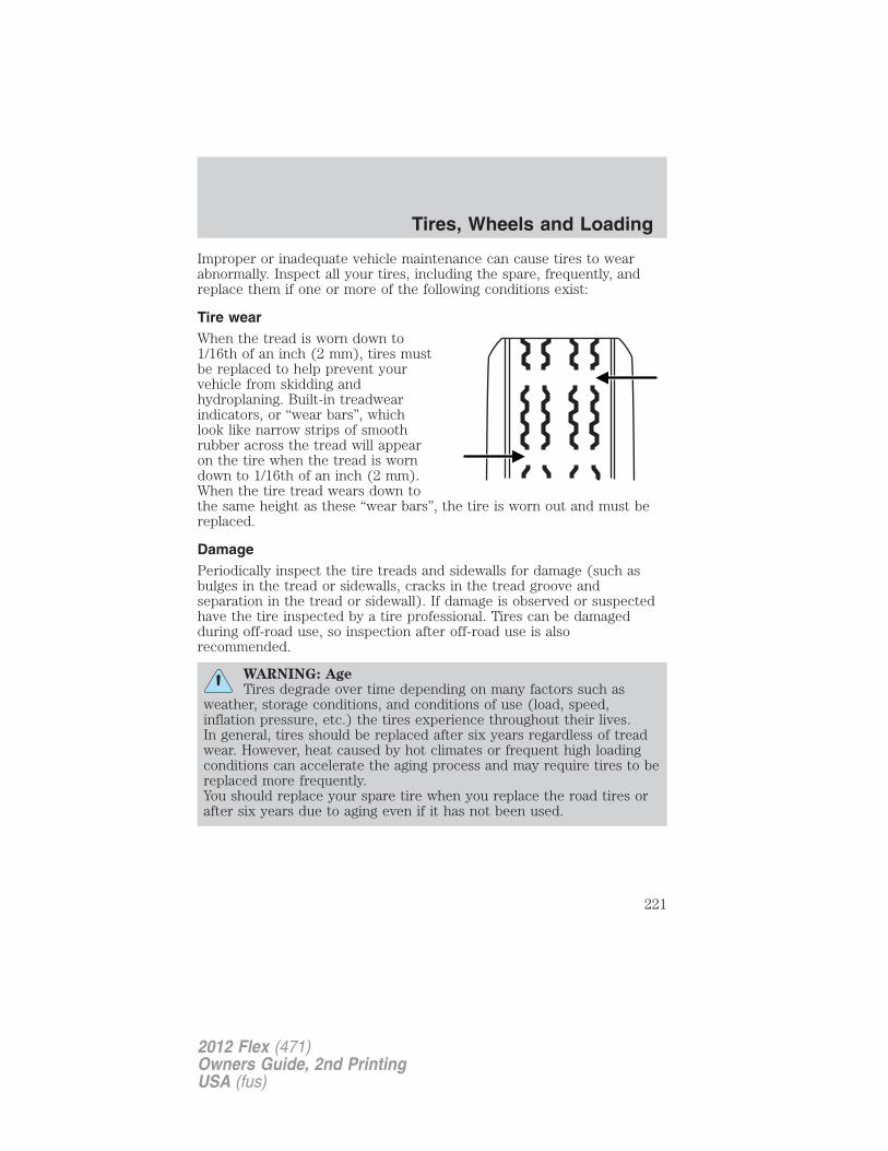
Improper or inadequate vehicle maintenance can cause tires to wearabnormally. Inspect all your tires, including the spare, frequently, andreplace them if one or more of the following conditions exist:
Tire wearWhen the tread is worn down to1/16th of an inch (2 mm), tires mustbe replaced to help prevent yourvehicle from skidding andhydroplaning. Built-in treadwearindicators, or “wear bars”, whichlook like narrow strips of smoothrubber across the tread will appearon the tire when the tread is worndown to 1/16th of an inch (2 mm).When the tire tread wears down tothe same height as these “wear bars”, the tire is worn out and must bereplaced.
DamagePeriodically inspect the tire treads and sidewalls for damage (such asbulges in the tread or sidewalls, cracks in the tread groove andseparation in the tread or sidewall). If damage is observed or suspectedhave the tire inspected by a tire professional. Tires can be damagedduring off-road use, so inspection after off-road use is alsorecommended.
WARNING: AgeTires degrade over time depending on many factors such as
weather, storage conditions, and conditions of use (load, speed,inflation pressure, etc.) the tires experience throughout their lives.In general, tires should be replaced after six years regardless of treadwear. However, heat caused by hot climates or frequent high loadingconditions can accelerate the aging process and may require tires to bereplaced more frequently.You should replace your spare tire when you replace the road tires orafter six years due to aging even if it has not been used.
Tires, Wheels and Loading
221
2012 Flex (471)Owners Guide, 2nd PrintingUSA (fus)
U.S. DOT Tire Identification Number (TIN)Both U.S. and Canada Federal regulations require tire manufacturers toplace standardized information on the sidewall of all tires. Thisinformation identifies and describes the fundamental characteristics ofthe tire and also provides a U.S. DOT Tire Identification Number forsafety standard certification and in case of a recall.
This begins with the letters “DOT” and indicates that the tire meets allfederal standards. The next two numbers or letters are the plant codedesignating where it was manufactured, the next two are the tire sizecode and the last four numbers represent the week and year the tire wasbuilt. For example, the numbers 317 mean the 31st week of 1997. After2000 the numbers go to four digits. For example, 2501 means the 25thweek of 2001. The numbers in between are identification codes used fortraceability. This information is used to contact customers if a tire defectrequires a recall.
Tire Replacement RequirementsYour vehicle is equipped with tires designed to provide a safe ride andhandling capability.
WARNING: Only use replacement tires and wheels that are thesame size, load index, speed rating and type (such as P-metric
versus LT-metric or all-season versus all-terrain) as those originallyprovided by Ford. The recommended tire and wheel size may be foundon either the Safety Compliance Certification Label or the Tire Labelwhich is located on the B-Pillar or edge of the driver’s door. If thisinformation is not found on these labels then you should contact yourauthorized dealer as soon as possible. Use of any tire or wheel notrecommended by Ford can affect the safety and performance of yourvehicle, which could result in an increased risk of loss of vehiclecontrol, vehicle rollover, personal injury and death. Additionally the useof non-recommended tires and wheels could cause steering,suspension, axle or transfer case/power transfer unit failure. If youhave questions regarding tire replacement, contact your authorizeddealer as soon as possible.
Tires, Wheels and Loading
222
2012 Flex (471)Owners Guide, 2nd PrintingUSA (fus)
WARNING: When mounting replacement tires and wheels, youshould not exceed the maximum pressure indicated on the
sidewall of the tire to set the beads without additional precautionslisted below. If the beads do not seat at the maximum pressureindicated, re-lubricate and try again.When inflating the tire for mounting pressures up to 20 psi (1.38 bar)greater than the maximum pressure on the tire sidewall, the followingprecautions must be taken to protect the person mounting the tire:
1. Make sure that you have the correct tire and wheel size.
2. Lubricate the tire bead and wheel bead seat area again.
3. Stand at a minimum of 12 ft (3.66 m) away from the tire wheelassembly.
4. Use both eye and ear protection.For a mounting pressure more than 20 psi (1.38 bar) greater than themaximum pressure, a Ford dealer or other tire service professionalshould do the mounting.Always inflate steel carcass tires with a remote air fill with the personinflating standing at a minimum of 12 ft (3.66 m) away from the tirewheel assembly.
Important: Remember to replace the wheel valve stems when the roadtires are replaced on your vehicle.
It is recommended that the two front tires or two rear tires generally bereplaced as a pair.
The tire pressure sensors mounted in the wheels (originally installed onyour vehicle) are not designed to be used in aftermarket wheels.
The use of wheels or tires not recommended by Ford Motor Companymay affect the operation of your tire pressure monitoring system.
If the TPMS indicator is flashing, your TPMS is malfunctioning. Yourreplacement tire might be incompatible with your TPMS, or somecomponent of the TPMS may be damaged.
Tires, Wheels and Loading
223
2012 Flex (471)Owners Guide, 2nd PrintingUSA (fus)
Safety Practices
WARNING: If your vehicle is stuck in snow, mud, sand, etc., donot rapidly spin the tires; spinning the tires can tear the tire and
cause an explosion. A tire can explode in as little as three to fiveseconds.
WARNING: Do not spin the wheels at over 35 mph (56 km/h).The tires may fail and injure a passenger or bystander.
Driving habits have a great deal to do with your tire mileage and safety.
• Observe posted speed limits
• Avoid fast starts, stops and turns
• Avoid potholes and objects on the road
• Do not run over curbs or hit the tire against a curb when parking
Highway hazardsNo matter how carefully you drive there’s always the possibility that youmay eventually have a flat tire on the highway. Drive slowly to theclosest safe area out of traffic. This may further damage the flat tire, butyour safety is more important.
If you feel a sudden vibration or ride disturbance while driving, or yoususpect your tire or vehicle has been damaged, immediately reduce yourspeed. Drive with caution until you can safely pull off the road. Stop andinspect the tires for damage. If a tire is under-inflated or damaged,deflate it, remove wheel and replace it with your spare tire and wheel. Ifyou cannot detect a cause, have the vehicle towed to the nearest repairfacility or tire dealer to have the vehicle inspected.
Tire and Wheel AlignmentA bad jolt from hitting a curb or pothole can cause the front end of yourvehicle to become misaligned or cause damage to your tires. If yourvehicle seems to pull to one side when you’re driving, the wheels may beout of alignment. Have an authorized dealer check the wheel alignmentperiodically.
Wheel misalignment in the front or the rear can cause uneven and rapidtreadwear of your tires and should be corrected by an authorized dealer.Front-wheel drive (FWD) vehicles and those with an independent rearsuspension (if equipped) may require alignment of all four wheels.
Tires, Wheels and Loading
224
2012 Flex (471)Owners Guide, 2nd PrintingUSA (fus)
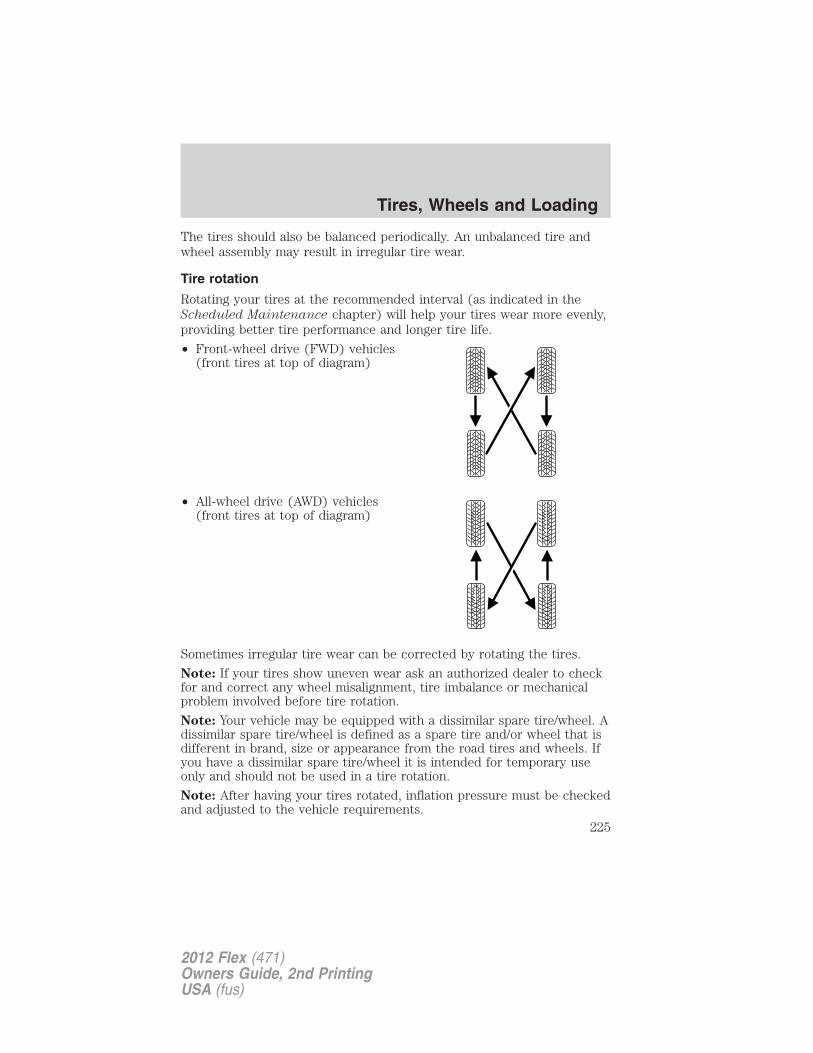
The tires should also be balanced periodically. An unbalanced tire andwheel assembly may result in irregular tire wear.
Tire rotation
Rotating your tires at the recommended interval (as indicated in theScheduled Maintenance chapter) will help your tires wear more evenly,providing better tire performance and longer tire life.
• Front-wheel drive (FWD) vehicles(front tires at top of diagram)
• All-wheel drive (AWD) vehicles(front tires at top of diagram)
Sometimes irregular tire wear can be corrected by rotating the tires.
Note: If your tires show uneven wear ask an authorized dealer to checkfor and correct any wheel misalignment, tire imbalance or mechanicalproblem involved before tire rotation.
Note: Your vehicle may be equipped with a dissimilar spare tire/wheel. Adissimilar spare tire/wheel is defined as a spare tire and/or wheel that isdifferent in brand, size or appearance from the road tires and wheels. Ifyou have a dissimilar spare tire/wheel it is intended for temporary useonly and should not be used in a tire rotation.
Note: After having your tires rotated, inflation pressure must be checkedand adjusted to the vehicle requirements.
Tires, Wheels and Loading
225
2012 Flex (471)Owners Guide, 2nd PrintingUSA (fus)
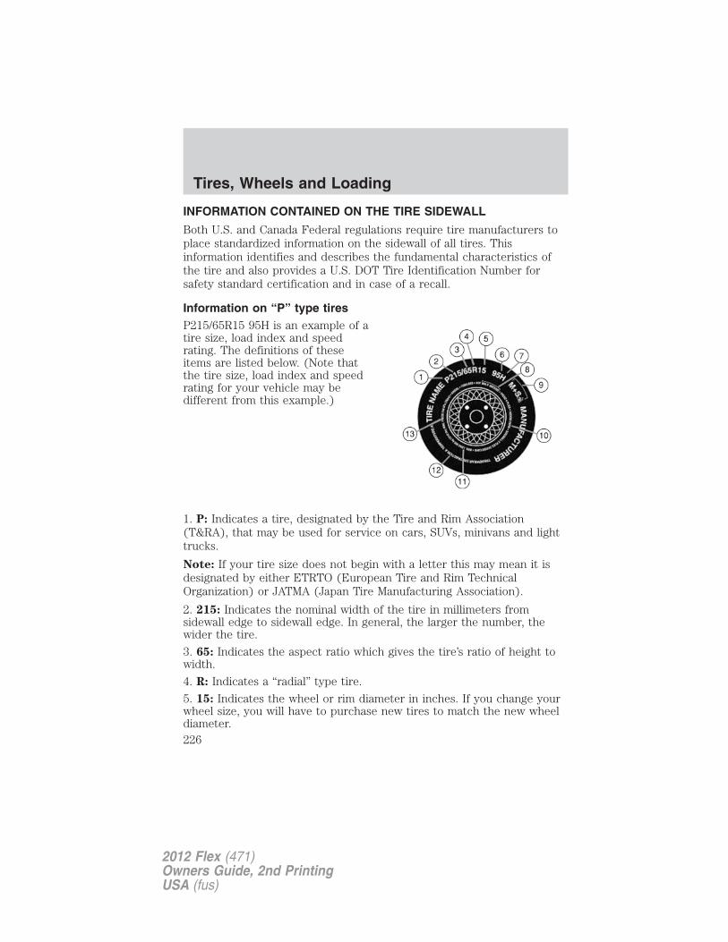
INFORMATION CONTAINED ON THE TIRE SIDEWALL
Both U.S. and Canada Federal regulations require tire manufacturers toplace standardized information on the sidewall of all tires. Thisinformation identifies and describes the fundamental characteristics ofthe tire and also provides a U.S. DOT Tire Identification Number forsafety standard certification and in case of a recall.
Information on “P” type tiresP215/65R15 95H is an example of atire size, load index and speedrating. The definitions of theseitems are listed below. (Note thatthe tire size, load index and speedrating for your vehicle may bedifferent from this example.)
1. P: Indicates a tire, designated by the Tire and Rim Association(T&RA), that may be used for service on cars, SUVs, minivans and lighttrucks.
Note: If your tire size does not begin with a letter this may mean it isdesignated by either ETRTO (European Tire and Rim TechnicalOrganization) or JATMA (Japan Tire Manufacturing Association).
2. 215: Indicates the nominal width of the tire in millimeters fromsidewall edge to sidewall edge. In general, the larger the number, thewider the tire.
3. 65: Indicates the aspect ratio which gives the tire’s ratio of height towidth.
4. R: Indicates a “radial” type tire.
5. 15: Indicates the wheel or rim diameter in inches. If you change yourwheel size, you will have to purchase new tires to match the new wheeldiameter.
Tires, Wheels and Loading
226
2012 Flex (471)Owners Guide, 2nd PrintingUSA (fus)
6. 95: Indicates the tire’s load index. It is an index that relates to howmuch weight a tire can carry. You may find this information in yourowner’s guide. If not, contact a local tire dealer.
Note: You may not find this information on all tires because it is notrequired by federal law.
7. H: Indicates the tire’s speed rating. The speed rating denotes thespeed at which a tire is designed to be driven for extended periods oftime under a standard condition of load and inflation pressure. The tireson your vehicle may operate at different conditions for load and inflationpressure. These speed ratings may need to be adjusted for the differencein conditions. The ratings range from 81 mph (130 km/h) to 186 mph(299 km/h). These ratings are listed in the following chart.
Note: You may not find this information on all tires because it is notrequired by federal law.
Letter rating Speed rating - mph (km/h)
M 81 mph (130 km/h)N 87 mph (140 km/h)Q 99 mph (159 km/h)R 106 mph (171 km/h)S 112 mph (180 km/h)T 118 mph (190 km/h)U 124 mph (200 km/h)H 130 mph (210 km/h)V 149 mph (240 km/h)W 168 mph (270 km/h)Y 186 mph (299 km/h)
Note: For tires with a maximum speed capability over 149 mph(240 km/h), tire manufacturers sometimes use the letters ZR. Forthose with a maximum speed capability over 186 mph (299 km/h), tiremanufacturers always use the letters ZR.
Tires, Wheels and Loading
227
2012 Flex (471)Owners Guide, 2nd PrintingUSA (fus)
8. U.S. DOT Tire Identification Number (TIN): This begins with theletters “DOT” and indicates that the tire meets all federal standards. Thenext two numbers or letters are the plant code designating where it wasmanufactured, the next two are the tire size code and the last fournumbers represent the week and year the tire was built. For example,the numbers 317 mean the 31st week of 1997. After 2000 the numbersgo to four digits. For example, 2501 means the 25th week of 2001. Thenumbers in between are identification codes used for traceability. Thisinformation is used to contact customers if a tire defect requires a recall.
9. M+S or M/S: Mud and Snow, orAT: All Terrain, orAS: All Season.
10. Tire Ply Composition and Material Used: Indicates the number ofplies or the number of layers of rubber-coated fabric in the tire tread andsidewall. Tire manufacturers also must indicate the ply materials in thetire and the sidewall, which include steel, nylon, polyester, and others.
11. Maximum Load: Indicates the maximum load in kilograms andpounds that can be carried by the tire. Refer to the Safety ComplianceCertification Label, which is located on the B-Pillar or the edge of thedriver’s door, for the correct tire pressure for your vehicle.
12. Treadwear, Traction and Temperature Grades
• Treadwear: The treadwear grade is a comparative rating based on thewear rate of the tire when tested under controlled conditions on aspecified government test course. For example, a tire graded 150would wear one and one-half (11⁄2) times as well on the governmentcourse as a tire graded 100.
• Traction: The traction grades, from highest to lowest are AA, A, B,and C. The grades represent the tire’s ability to stop on wet pavementas measured under controlled conditions on specified government testsurfaces of asphalt and concrete. A tire marked C may have poortraction performance.
• Temperature: The temperature grades are A (the highest), B and C,representing the tire’s resistance to the generation of heat and itsability to dissipate heat when tested under controlled conditions on aspecified indoor laboratory test wheel.
Tires, Wheels and Loading
228
2012 Flex (471)Owners Guide, 2nd PrintingUSA (fus)
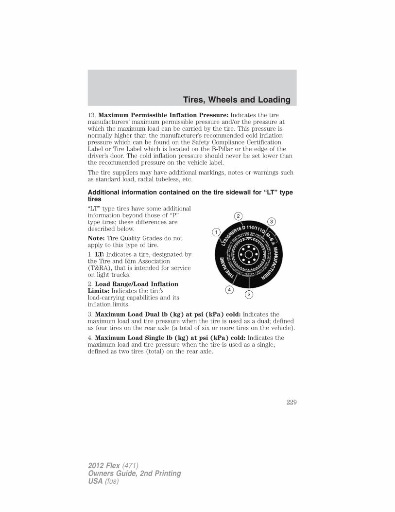
13. Maximum Permissible Inflation Pressure: Indicates the tiremanufacturers’ maximum permissible pressure and/or the pressure atwhich the maximum load can be carried by the tire. This pressure isnormally higher than the manufacturer’s recommended cold inflationpressure which can be found on the Safety Compliance CertificationLabel or Tire Label which is located on the B-Pillar or the edge of thedriver’s door. The cold inflation pressure should never be set lower thanthe recommended pressure on the vehicle label.
The tire suppliers may have additional markings, notes or warnings suchas standard load, radial tubeless, etc.
Additional information contained on the tire sidewall for “LT” typetires“LT” type tires have some additionalinformation beyond those of “P”type tires; these differences aredescribed below.
Note: Tire Quality Grades do notapply to this type of tire.
1. LT: Indicates a tire, designated bythe Tire and Rim Association(T&RA), that is intended for serviceon light trucks.
2. Load Range/Load InflationLimits: Indicates the tire’sload-carrying capabilities and itsinflation limits.
3. Maximum Load Dual lb (kg) at psi (kPa) cold: Indicates themaximum load and tire pressure when the tire is used as a dual; definedas four tires on the rear axle (a total of six or more tires on the vehicle).
4. Maximum Load Single lb (kg) at psi (kPa) cold: Indicates themaximum load and tire pressure when the tire is used as a single;defined as two tires (total) on the rear axle.
Tires, Wheels and Loading
229
2012 Flex (471)Owners Guide, 2nd PrintingUSA (fus)
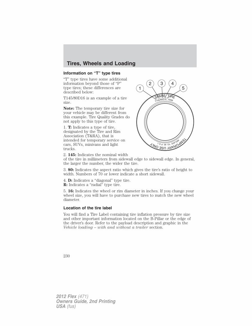
Information on “T” type tires“T” type tires have some additionalinformation beyond those of “P”type tires; these differences aredescribed below:
T145/80D16 is an example of a tiresize.
Note: The temporary tire size foryour vehicle may be different fromthis example. Tire Quality Grades donot apply to this type of tire.
1. T: Indicates a type of tire,designated by the Tire and RimAssociation (T&RA), that isintended for temporary service oncars, SUVs, minivans and lighttrucks.
2. 145: Indicates the nominal widthof the tire in millimeters from sidewall edge to sidewall edge. In general,the larger the number, the wider the tire.
3. 80: Indicates the aspect ratio which gives the tire’s ratio of height towidth. Numbers of 70 or lower indicate a short sidewall.
4. D: Indicates a “diagonal” type tire.R: Indicates a “radial” type tire.
5. 16: Indicates the wheel or rim diameter in inches. If you change yourwheel size, you will have to purchase new tires to match the new wheeldiameter.
Location of the tire label
You will find a Tire Label containing tire inflation pressure by tire sizeand other important information located on the B-Pillar or the edge ofthe driver’s door. Refer to the payload description and graphic in theVehicle loading – with and without a trailer section.
Tires, Wheels and Loading
230
2012 Flex (471)Owners Guide, 2nd PrintingUSA (fus)
TIRE PRESSURE MONITORING SYSTEM (TPMS)Each tire, including the spare (ifprovided), should be checkedmonthly when cold and inflated tothe inflation pressure recommendedby the vehicle manufacturer on thevehicle placard or tire inflation pressure label. (If your vehicle has tiresof a different size than the size indicated on the vehicle placard or tireinflation pressure label, you should determine the proper tire inflationpressure for those tires.)
As an added safety feature, your vehicle has been equipped with a tirepressure monitoring system (TPMS) that illuminates a low tire pressuretelltale when one or more of your tires is significantly under-inflated.Accordingly, when the low tire pressure telltale illuminates, you shouldstop and check your tires as soon as possible, and inflate them to theproper pressure. Driving on a significantly under-inflated tire causes thetire to overheat and can lead to tire failure. Under-inflation also reducesfuel efficiency and tire tread life, and may affect the vehicle’s handlingand stopping ability.
Please note that the TPMS is not a substitute for proper tiremaintenance, and it is the driver’s responsibility to maintain correct tirepressure, even if under-inflation has not reached the level to triggerillumination of the TPMS low tire pressure telltale.
Your vehicle has also been equipped with a TPMS malfunction indicatorto indicate when the system is not operating properly. The TPMSmalfunction indicator is combined with the low tire pressure telltale.When the system detects a malfunction, the telltale will flash forapproximately one minute and then remain continuously illuminated.This sequence will continue upon subsequent vehicle start-ups as long asthe malfunction exists.
When the malfunction indicator is illuminated, the system may not beable to detect or signal low tire pressure as intended. TPMS malfunctionsmay occur for a variety of reasons, including the installation ofreplacement or alternate tires or wheels on the vehicle that prevent theTPMS from functioning properly. Always check the TPMS malfunctiontelltale after replacing one or more tires or wheels on your vehicle toensure that the replacement or alternate tires and wheels allow theTPMS to continue to function properly.
The tire pressure monitoring system complies with part 15 of the FCCrules and with RSS-210 of Industry Canada. Operation is subject to the
Tires, Wheels and Loading
231
2012 Flex (471)Owners Guide, 2nd PrintingUSA (fus)
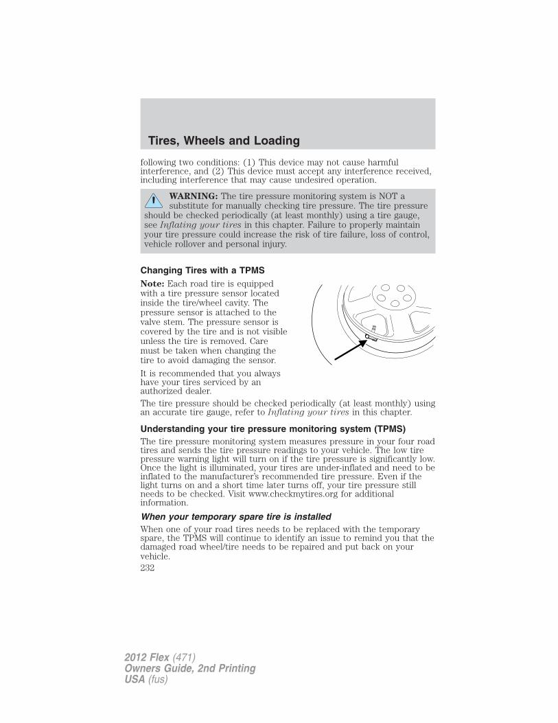
following two conditions: (1) This device may not cause harmfulinterference, and (2) This device must accept any interference received,including interference that may cause undesired operation.
WARNING: The tire pressure monitoring system is NOT asubstitute for manually checking tire pressure. The tire pressure
should be checked periodically (at least monthly) using a tire gauge,see Inflating your tires in this chapter. Failure to properly maintainyour tire pressure could increase the risk of tire failure, loss of control,vehicle rollover and personal injury.
Changing Tires with a TPMSNote: Each road tire is equippedwith a tire pressure sensor locatedinside the tire/wheel cavity. Thepressure sensor is attached to thevalve stem. The pressure sensor iscovered by the tire and is not visibleunless the tire is removed. Caremust be taken when changing thetire to avoid damaging the sensor.
It is recommended that you alwayshave your tires serviced by anauthorized dealer.The tire pressure should be checked periodically (at least monthly) usingan accurate tire gauge, refer to Inflating your tires in this chapter.
Understanding your tire pressure monitoring system (TPMS)The tire pressure monitoring system measures pressure in your four roadtires and sends the tire pressure readings to your vehicle. The low tirepressure warning light will turn on if the tire pressure is significantly low.Once the light is illuminated, your tires are under-inflated and need to beinflated to the manufacturer’s recommended tire pressure. Even if thelight turns on and a short time later turns off, your tire pressure stillneeds to be checked. Visit www.checkmytires.org for additionalinformation.
When your temporary spare tire is installedWhen one of your road tires needs to be replaced with the temporaryspare, the TPMS will continue to identify an issue to remind you that thedamaged road wheel/tire needs to be repaired and put back on yourvehicle.
Tires, Wheels and Loading
232
2012 Flex (471)Owners Guide, 2nd PrintingUSA (fus)
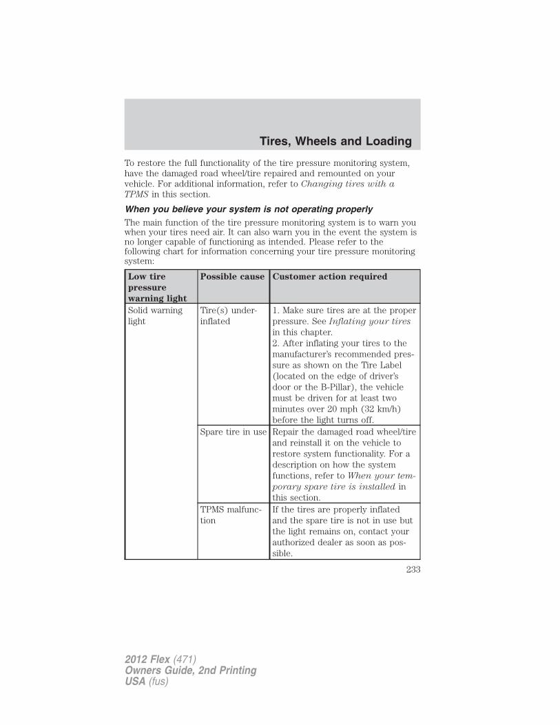
To restore the full functionality of the tire pressure monitoring system,have the damaged road wheel/tire repaired and remounted on yourvehicle. For additional information, refer to Changing tires with a
TPMS in this section.
When you believe your system is not operating properlyThe main function of the tire pressure monitoring system is to warn youwhen your tires need air. It can also warn you in the event the system isno longer capable of functioning as intended. Please refer to thefollowing chart for information concerning your tire pressure monitoringsystem:
Low tire
pressure
warning light
Possible cause Customer action required
Solid warninglight
Tire(s) under-inflated
1. Make sure tires are at the properpressure. See Inflating your tires
in this chapter.2. After inflating your tires to themanufacturer’s recommended pres-sure as shown on the Tire Label(located on the edge of driver’sdoor or the B-Pillar), the vehiclemust be driven for at least twominutes over 20 mph (32 km/h)before the light turns off.
Spare tire in use Repair the damaged road wheel/tireand reinstall it on the vehicle torestore system functionality. For adescription on how the systemfunctions, refer to When your tem-
porary spare tire is installed inthis section.
TPMS malfunc-tion
If the tires are properly inflatedand the spare tire is not in use butthe light remains on, contact yourauthorized dealer as soon as pos-sible.
Tires, Wheels and Loading
233
2012 Flex (471)Owners Guide, 2nd PrintingUSA (fus)
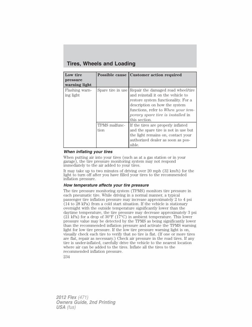
Low tire
pressure
warning light
Possible cause Customer action required
Flashing warn-ing light
Spare tire in use Repair the damaged road wheel/tireand reinstall it on the vehicle torestore system functionality. For adescription on how the systemfunctions, refer to When your tem-
porary spare tire is installed inthis section.
TPMS malfunc-tion
If the tires are properly inflatedand the spare tire is not in use butthe light remains on, contact yourauthorized dealer as soon as pos-sible.
When inflating your tiresWhen putting air into your tires (such as at a gas station or in yourgarage), the tire pressure monitoring system may not respondimmediately to the air added to your tires.It may take up to two minutes of driving over 20 mph (32 km/h) for thelight to turn off after you have filled your tires to the recommendedinflation pressure.
How temperature affects your tire pressureThe tire pressure monitoring system (TPMS) monitors tire pressure ineach pneumatic tire. While driving in a normal manner, a typicalpassenger tire inflation pressure may increase approximately 2 to 4 psi(14 to 28 kPa) from a cold start situation. If the vehicle is stationaryovernight with the outside temperature significantly lower than thedaytime temperature, the tire pressure may decrease approximately 3 psi(21 kPa) for a drop of 30°F (17°C) in ambient temperature. This lowerpressure value may be detected by the TPMS as being significantly lowerthan the recommended inflation pressure and activate the TPMS warninglight for low tire pressure. If the low tire pressure warning light is on,visually check each tire to verify that no tire is flat. (If one or more tiresare flat, repair as necessary.) Check air pressure in the road tires. If anytire is under-inflated, carefully drive the vehicle to the nearest locationwhere air can be added to the tires. Inflate all the tires to therecommended inflation pressure.
Tires, Wheels and Loading
234
2012 Flex (471)Owners Guide, 2nd PrintingUSA (fus)
SNOW TIRES AND CABLES/CHAINS
WARNING: Snow tires must be the same size, load index, speedrating as those originally provided by Ford. Use of any tire or
wheel not recommended by Ford can affect the safety andperformance of your vehicle, which could result in an increased risk ofloss of vehicle control, vehicle rollover, personal injury and death.Additionally, the use of non-recommended tires and wheels couldcause steering, suspension, axle or transfer case/power transfer unitfailure.
The tires on your vehicle have all-weather treads to provide traction inrain and snow. However, in some climates, you may need to use snowtires and cables . If you need to use cables, it is recommended that steelwheels (of the same size and specifications) be used, as cables may chipaluminum wheels.
Note: The suspension insulation and bumpers will help prevent vehicledamage. Do not remove these components from your vehicle when usingsnow tires and chains.
Follow these guidelines when using snow tires and chains:
• If possible, avoid fully loading your vehicle.
• Use only SAE Class S cables or equivalent on the front axle forP235/60R17, P235/60R18, and P235/55R19 equipped vehicles. SAEClass S chains or other conventional link chains may cause damage tothe vehicles wheel house and/or body. Use of optional spike typetraction devices or equivalent is also acceptable.
• Do not install tire chains, cables, or optional traction devices on therear tires. This could cause damage to the vehicle’s wheel house orbody.
• Do not use tire chains, cables, or optional traction devices with255/45R20 tires.
• Install cable chains securely, verifying that the cables do not touch anywiring, brake lines or fuel lines.
Tires, Wheels and Loading
235
2012 Flex (471)Owners Guide, 2nd PrintingUSA (fus)
• Do not exceed 30 mph (48 km/h) with tire cables on your vehicle.
• Drive cautiously. If you hear the cables rub or bang against yourvehicle, stop and retighten the cables. If this does not work, removethe cables to prevent damage to your vehicle.
• Remove the tire cables when they are no longer needed. Do not usetire cables on dry roads.
VEHICLE LOADING – WITH AND WITHOUT A TRAILER
This section will guide you in the proper loading of your vehicle and/ortrailer, to keep your loaded vehicle weight within its design ratingcapability, with or without a trailer. Properly loading your vehicle willprovide maximum return of vehicle design performance. Before loadingyour vehicle, familiarize yourself with the following terms for determiningyour vehicle’s weight ratings, with or without a trailer, from the vehicle’sTire Label or Safety Compliance Certification Label:
Base Curb Weight – is the weight of the vehicle including a full tank offuel and all standard equipment. It does not include passengers, cargo, oroptional equipment.
Vehicle Curb Weight – is the weight of your new vehicle when youpicked it up from your authorized dealer plus any aftermarketequipment.
Tires, Wheels and Loading
236
2012 Flex (471)Owners Guide, 2nd PrintingUSA (fus)
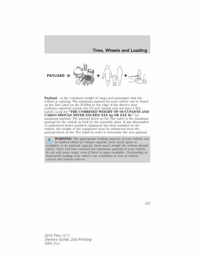
Payload – is the combined weight of cargo and passengers that thevehicle is carrying. The maximum payload for your vehicle can be foundon the Tire Label on the B-Pillar or the edge of the driver’s door(vehicles exported outside the US and Canada may not have a TireLabel). Look for “THE COMBINED WEIGHT OF OCCUPANTS ANDCARGO SHOULD NEVER EXCEED XXX kg OR XXX lb.” formaximum payload. The payload listed on the Tire Label is the maximumpayload for the vehicle as built by the assembly plant. If any aftermarketor authorized-dealer installed equipment has been installed on thevehicle, the weight of the equipment must be subtracted from thepayload listed on the Tire Label in order to determine the new payload.
WARNING: The appropriate loading capacity of your vehicle canbe limited either by volume capacity (how much space is
available) or by payload capacity (how much weight the vehicle shouldcarry). Once you have reached the maximum payload of your vehicle,do not add more cargo, even if there is space available. Overloading orimproperly loading your vehicle can contribute to loss of vehiclecontrol and vehicle rollover.
Tires, Wheels and Loading
237
2012 Flex (471)Owners Guide, 2nd PrintingUSA (fus)
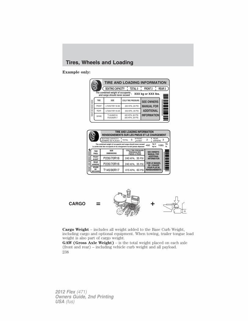
Example only:
Cargo Weight – includes all weight added to the Base Curb Weight,including cargo and optional equipment. When towing, trailer tongue loadweight is also part of cargo weight.GAW (Gross Axle Weight) – is the total weight placed on each axle(front and rear) – including vehicle curb weight and all payload.
Tires, Wheels and Loading
238
2012 Flex (471)Owners Guide, 2nd PrintingUSA (fus)
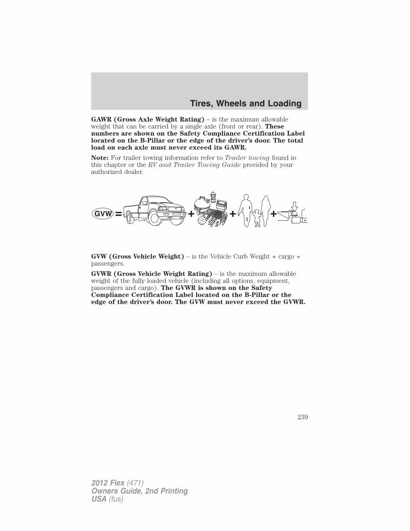
GAWR (Gross Axle Weight Rating) – is the maximum allowableweight that can be carried by a single axle (front or rear). Thesenumbers are shown on the Safety Compliance Certification Labellocated on the B-Pillar or the edge of the driver’s door. The totalload on each axle must never exceed its GAWR.
Note: For trailer towing information refer to Trailer towing found inthis chapter or the RV and Trailer Towing Guide provided by yourauthorized dealer.
GVW (Gross Vehicle Weight) – is the Vehicle Curb Weight + cargo +passengers.
GVWR (Gross Vehicle Weight Rating) – is the maximum allowableweight of the fully loaded vehicle (including all options, equipment,passengers and cargo). The GVWR is shown on the SafetyCompliance Certification Label located on the B-Pillar or theedge of the driver’s door. The GVW must never exceed the GVWR.
Tires, Wheels and Loading
239
2012 Flex (471)Owners Guide, 2nd PrintingUSA (fus)
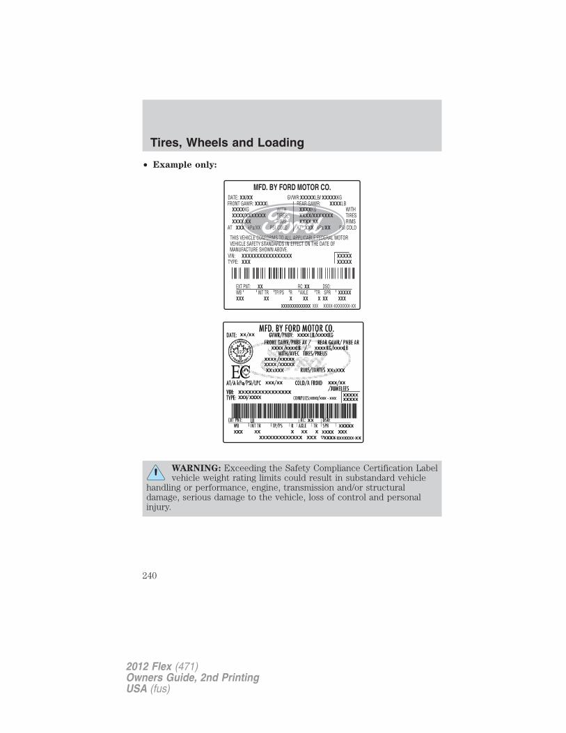
• Example only:
WARNING: Exceeding the Safety Compliance Certification Labelvehicle weight rating limits could result in substandard vehicle
handling or performance, engine, transmission and/or structuraldamage, serious damage to the vehicle, loss of control and personalinjury.
Tires, Wheels and Loading
240
2012 Flex (471)Owners Guide, 2nd PrintingUSA (fus)
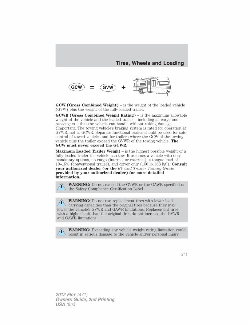
GCW (Gross Combined Weight) – is the weight of the loaded vehicle(GVW) plus the weight of the fully loaded trailer.
GCWR (Gross Combined Weight Rating) – is the maximum allowableweight of the vehicle and the loaded trailer – including all cargo andpassengers – that the vehicle can handle without risking damage.(Important: The towing vehicle’s braking system is rated for operation atGVWR, not at GCWR. Separate functional brakes should be used for safecontrol of towed vehicles and for trailers where the GCW of the towingvehicle plus the trailer exceed the GVWR of the towing vehicle. TheGCW must never exceed the GCWR.
Maximum Loaded Trailer Weight – is the highest possible weight of afully loaded trailer the vehicle can tow. It assumes a vehicle with onlymandatory options, no cargo (internal or external), a tongue load of10–15% (conventional trailer), and driver only (150 lb. [68 kg]). Consultyour authorized dealer (or the RV and Trailer Towing Guideprovided by your authorized dealer) for more detailedinformation.
WARNING: Do not exceed the GVWR or the GAWR specified onthe Safety Compliance Certification Label.
WARNING: Do not use replacement tires with lower loadcarrying capacities than the original tires because they may
lower the vehicle’s GVWR and GAWR limitations. Replacement tireswith a higher limit than the original tires do not increase the GVWRand GAWR limitations.
WARNING: Exceeding any vehicle weight rating limitation couldresult in serious damage to the vehicle and/or personal injury.
Tires, Wheels and Loading
241
2012 Flex (471)Owners Guide, 2nd PrintingUSA (fus)
Steps for determining the correct load limit:
1. Locate the statement “The combined weight of occupants and cargoshould never exceed XXX kg or XXX lbs.” on your vehicle’s placard.2. Determine the combined weight of the driver and passengers that willbe riding in your vehicle.
3. Subtract the combined weight of the driver and passengers from XXXkg or XXX lbs.
4. The resulting figure equals the available amount of cargo and luggageload capacity. For example, if the “XXX” amount equals 1,400 lbs. andthere will be five 150 lb. passengers in your vehicle, the amount ofavailable cargo and luggage load capacity is 650 lbs. (1400–750 (5 x 150)= 650 lb.). In metric units (635–340 (5 x 68) = 295 kg.)
5. Determine the combined weight of luggage and cargo being loaded onthe vehicle. That weight may not safely exceed the available cargo andluggage load capacity calculated in Step 4.
6. If your vehicle will be towing a trailer, load from your trailer will betransferred to your vehicle. Consult this manual to determine how thisreduces the available cargo and luggage load capacity of your vehicle.
The following gives you a few examples on how to calculate the availableamount of cargo and luggage load capacity:
• Another example for your vehicle with 1,400 lb. (635 kg) of cargo andluggage capacity. You decide to go golfing. Is there enough loadcapacity to carry you, 4 of your friends and all the golf bags? You andfour friends average 220 lb. (99 kg) each and the golf bags weighapproximately 30 lb. (13.5 kg) each. The calculation would be: 1,400 -(5 x 220) - (5 x 30) = 1,400 - 1,100 - 150 = 150 lb. Yes, you haveenough load capacity in your vehicle to transport four friends andyour golf bags. In metric units, the calculation would be: 635 kg - (5 x99 kg) - (5 x 13.5 kg) = 635 - 495 - 67.5 = 72.5 kg.
• A final example for your vehicle with 1,400 lb. (635 kg) of cargo andluggage capacity. You and one of your friends decide to pick upcement from the local home improvement store to finish that patioyou have been planning for the past 2 years. Measuring the inside ofthe vehicle with the rear seat folded down, you have room for12-100 lb. (45 kg) bags of cement. Do you have enough load capacityto transport the cement to your home? If you and your friend eachweigh 220 lb. (99 kg), the calculation would be: 1,400 - (2 x 220) -(12 x 100) = 1,400 - 440 - 1,200 = - 240 lb. No, you do not haveenough cargo capacity to carry that much weight. In metric units, the
Tires, Wheels and Loading
242
2012 Flex (471)Owners Guide, 2nd PrintingUSA (fus)
calculation would be: 635 kg - (2 x 99 kg) - (12 x 45 kg) = 635 - 198 -540 = -103 kg. You will need to reduce the load weight by at least240 lb. (104 kg). If you remove 3-100 lb. (45 kg) cement bags, thenthe load calculation would be:
1,400 - (2 x 220) - (9 x 100) = 1,400 - 440 - 900 = 60 lb. Now youhave the load capacity to transport the cement and your friend home.In metric units, the calculation would be: 635 kg - (2 x 99 kg) - (9 x45 kg) = 635 - 198 - 405 = 32 kg.
The above calculations also assume that the loads are positioned in yourvehicle in a manner that does not overload the Front or the Rear GrossAxle Weight Rating specified for your vehicle on the Safety ComplianceCertification Label found on the edge of the driver’s door.
TRAILER TOWINGTrailer towing puts additional loads on your vehicle’s engine,transmission, axle, brakes, tires and suspension. For your safety and tomaximize vehicle performance, be sure to use the proper equipmentwhile towing.
Follow these guidelines to ensure safe towing:
• Do not tow a trailer until your vehicle has been driven at least1,000 miles (1,600 km).
• Consult your local motor vehicle laws for towing a trailer.
• Refer to the instructions included with towing accessories for theproper installation and adjustment specifications.
• Thoroughly prepare your vehicle for towing. Refer to Preparing totow in this chapter.
• Stay within your vehicle’s load limits.
• Use extra caution when driving while trailer towing. Refer to Drivingwhile you tow in this section.
• Service your vehicle more frequently if you tow a trailer. Refer toSpecial operating conditions in your scheduled maintenance.
For load specification terms found on the label, refer to Vehicle loading– with and without a trailer in this chapter. Remember to figure in thetongue load of your loaded vehicle when figuring the total weight.
WARNING: Do not exceed the GVWR or the GAWR specified onthe certification label.
Tires, Wheels and Loading
243
2012 Flex (471)Owners Guide, 2nd PrintingUSA (fus)
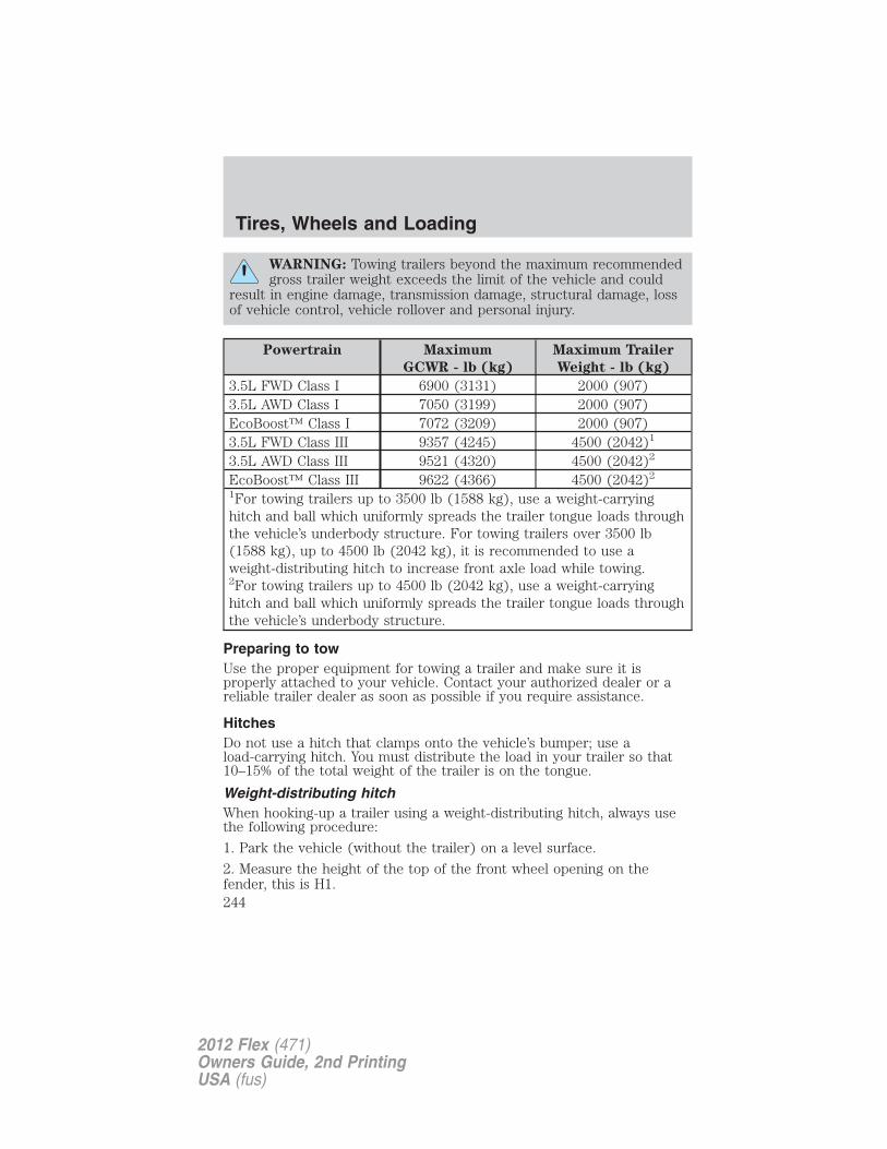
WARNING: Towing trailers beyond the maximum recommendedgross trailer weight exceeds the limit of the vehicle and could
result in engine damage, transmission damage, structural damage, lossof vehicle control, vehicle rollover and personal injury.
Powertrain Maximum
GCWR - lb (kg)
Maximum Trailer
Weight - lb (kg)
3.5L FWD Class I 6900 (3131) 2000 (907)3.5L AWD Class I 7050 (3199) 2000 (907)EcoBoost™ Class I 7072 (3209) 2000 (907)3.5L FWD Class III 9357 (4245) 4500 (2042)1
3.5L AWD Class III 9521 (4320) 4500 (2042)2
EcoBoost™ Class III 9622 (4366) 4500 (2042)2
1For towing trailers up to 3500 lb (1588 kg), use a weight-carryinghitch and ball which uniformly spreads the trailer tongue loads throughthe vehicle’s underbody structure. For towing trailers over 3500 lb(1588 kg), up to 4500 lb (2042 kg), it is recommended to use aweight-distributing hitch to increase front axle load while towing.2For towing trailers up to 4500 lb (2042 kg), use a weight-carryinghitch and ball which uniformly spreads the trailer tongue loads throughthe vehicle’s underbody structure.
Preparing to towUse the proper equipment for towing a trailer and make sure it isproperly attached to your vehicle. Contact your authorized dealer or areliable trailer dealer as soon as possible if you require assistance.
HitchesDo not use a hitch that clamps onto the vehicle’s bumper; use aload-carrying hitch. You must distribute the load in your trailer so that10–15% of the total weight of the trailer is on the tongue.
Weight-distributing hitchWhen hooking-up a trailer using a weight-distributing hitch, always usethe following procedure:
1. Park the vehicle (without the trailer) on a level surface.
2. Measure the height of the top of the front wheel opening on thefender, this is H1.
Tires, Wheels and Loading
244
2012 Flex (471)Owners Guide, 2nd PrintingUSA (fus)
3. Attach the trailer to the vehicle without the weight distributing barsconnected.
4. Measure the height of the top of the front wheel opening on thefender a second time, this is H2.
5. Install and adjust the tension in the weight distributing bars so thatthe height of the front fender is approximately halfway between H1 andH2.
6. Check that the trailer is level. If not level, adjust the ball heightaccordingly and repeat Steps 3–6.
WARNING: Do not adjust a weight-distributing hitch to anyposition where the rear bumper of the vehicle is higher than it
was before attaching the trailer. Doing so will defeat the function ofthe weight-distributing hitch, which may cause unpredictable handling,and could result in serious personal injury.
Safety chains
Always connect the trailer’s safety chains to the frame or hook retainersof the vehicle hitch. To connect the trailer’s safety chains, cross thechains under the trailer tongue and allow slack for turning corners.
If you use a rental trailer, follow the instructions that the rental agencygives to you.
Do not attach safety chains to the bumper.
Trailer brakes
Electric brakes and manual, automatic or surge-type trailer brakes aresafe if installed properly and adjusted to the manufacturer’sspecifications. The trailer brakes must meet local and Federalregulations.
WARNING: Do not connect a trailer’s hydraulic brake systemdirectly to your vehicle’s brake system. Your vehicle may not
have enough braking power and your chances of having a collisiongreatly increase.
The braking system of the tow vehicle is rated for operation at theGVWR not GCWR.
Tires, Wheels and Loading
245
2012 Flex (471)Owners Guide, 2nd PrintingUSA (fus)
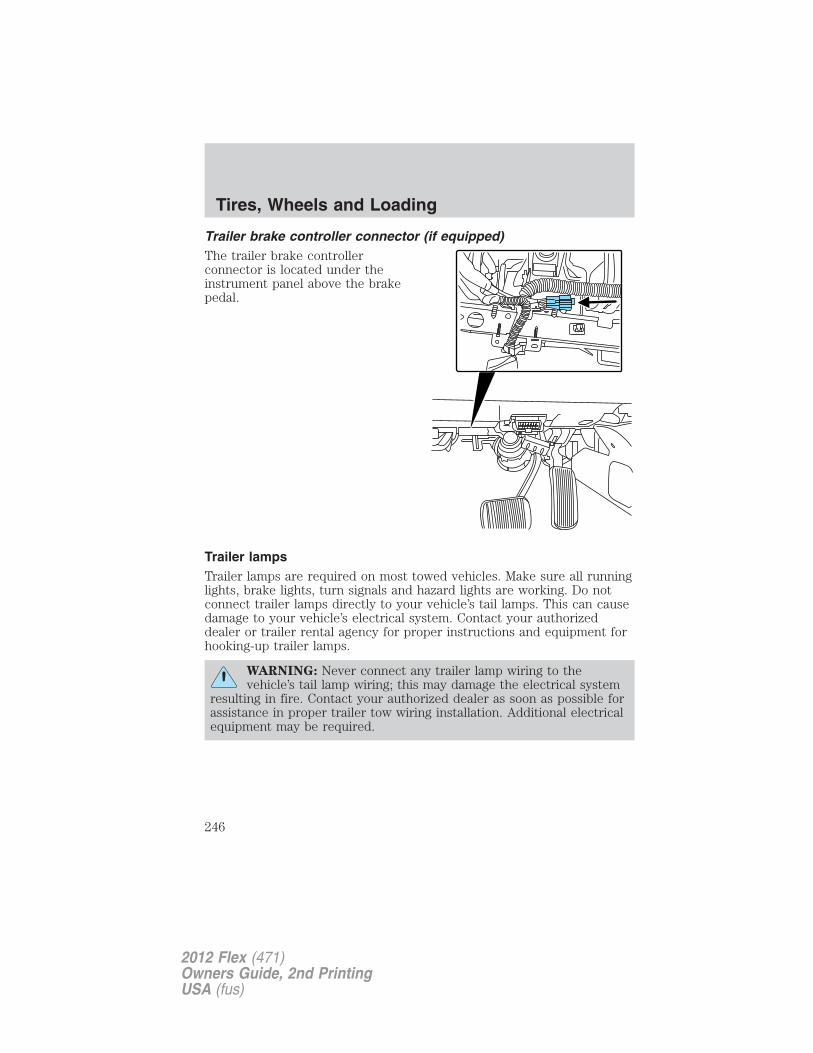
Trailer brake controller connector (if equipped)The trailer brake controllerconnector is located under theinstrument panel above the brakepedal.
Trailer lampsTrailer lamps are required on most towed vehicles. Make sure all runninglights, brake lights, turn signals and hazard lights are working. Do notconnect trailer lamps directly to your vehicle’s tail lamps. This can causedamage to your vehicle’s electrical system. Contact your authorizeddealer or trailer rental agency for proper instructions and equipment forhooking-up trailer lamps.
WARNING: Never connect any trailer lamp wiring to thevehicle’s tail lamp wiring; this may damage the electrical system
resulting in fire. Contact your authorized dealer as soon as possible forassistance in proper trailer tow wiring installation. Additional electricalequipment may be required.
Tires, Wheels and Loading
246
2012 Flex (471)Owners Guide, 2nd PrintingUSA (fus)
Driving while you towWhen towing a trailer:• Turn off the speed control. The speed control may shut off
automatically when you are towing on long, steep grades.• It is recommended to select the L (Low) or M (Manual) gear position
when additional engine braking is needed. In situations such asprolonged downhill driving on steep grades (i.e., driving inmountainous areas), additional engine braking is needed to reduce theload on the vehicle’s regular brake system to prevent them fromoverheating.
• Allow more distance for stopping with a trailer attached; anticipatestops and brake gradually.
Trailer towing tips• Practice turning, stopping and backing-up before starting on a trip to
get the feel of the vehicle-trailer combination. When turning, makewider turns so the trailer wheels will clear curbs and other obstacles.
• To aid in engine/transmission cooling and A/C efficiency during hotweather while stopped in traffic, place the gearshift lever in P (Park).
• After you have traveled 50 miles (80 km), thoroughly check yourhitch, electrical connections and trailer wheel lug nuts.
• If you are driving down a long or steep hill, shift to a lower gear. Donot apply the brakes continuously, as they may overheat and becomeless effective.
• Vehicles with trailers should not be parked on a grade. If you mustpark on a grade, place wheel chocks under the trailer’s wheels.
RECREATIONAL TOWINGFollow these guidelines for your specific powertrain combination to towyour vehicle for personal travel (such as behind a motor home or atruck).
Note: Put your climate control system in recirculated air mode toprevent exhaust fumes from entering the vehicle. Refer to the ClimateControls chapter for more information.
In case of a roadside emergency with a disabled vehicle, please refer toWrecker towing in the Roadside Emergencies chapter.
These guidelines are designed to prevent damage to your vehicle after itis hooked-up to the RV or tow dolly.
Tires, Wheels and Loading
247
2012 Flex (471)Owners Guide, 2nd PrintingUSA (fus)
Front-wheel drive (FWD) vehicles can be towed with all four wheelson the ground or with the front wheels off the ground by using a towdolly. If you are using a tow dolly follow the instructions specified by theequipment provider. If you are towing with all four wheels on the ground,refer to the towing instructions below.
All-wheel drive (AWD) vehicles can be towed with all four wheels onthe ground or with all four wheels off the ground using a vehicletransport trailer. Do not tow your AWD vehicle with the frontwheels off the ground (by using a tow dolly) and the rear wheelson the ground; this will cause damage to your AWD system. If youare using a vehicle transport trailer, follow the instruction specified bythe equipment provider. If you are towing with all four wheels on theground, refer to the towing instructions below.
If you tow your vehicle with all four wheels on the ground, follow theseinstructions:
• Tow only in the forward direction.
• Release the parking brake.
• Place the transmission shift lever in N (Neutral).
• Place the ignition in the accessory position (refer to Starting in theDriving chapter).
• Do not exceed 65 mph (105 km/h)
• Start the engine and allow it to run for five minutes at the beginningof each day and at each fuel stop.
Tires, Wheels and Loading
248
2012 Flex (471)Owners Guide, 2nd PrintingUSA (fus)
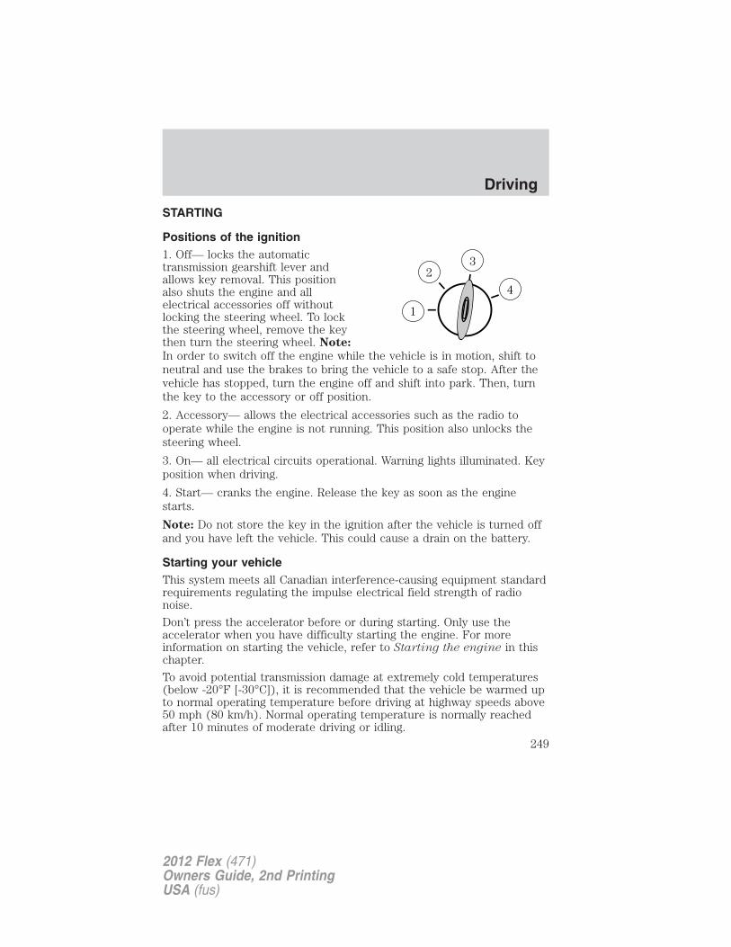
STARTING
Positions of the ignition1. Off— locks the automatictransmission gearshift lever andallows key removal. This positionalso shuts the engine and allelectrical accessories off withoutlocking the steering wheel. To lockthe steering wheel, remove the keythen turn the steering wheel. Note:
In order to switch off the engine while the vehicle is in motion, shift toneutral and use the brakes to bring the vehicle to a safe stop. After thevehicle has stopped, turn the engine off and shift into park. Then, turnthe key to the accessory or off position.
2. Accessory— allows the electrical accessories such as the radio tooperate while the engine is not running. This position also unlocks thesteering wheel.
3. On— all electrical circuits operational. Warning lights illuminated. Keyposition when driving.
4. Start— cranks the engine. Release the key as soon as the enginestarts.
Note: Do not store the key in the ignition after the vehicle is turned offand you have left the vehicle. This could cause a drain on the battery.
Starting your vehicleThis system meets all Canadian interference-causing equipment standardrequirements regulating the impulse electrical field strength of radionoise.
Don’t press the accelerator before or during starting. Only use theaccelerator when you have difficulty starting the engine. For moreinformation on starting the vehicle, refer to Starting the engine in thischapter.
To avoid potential transmission damage at extremely cold temperatures(below -20°F [-30°C]), it is recommended that the vehicle be warmed upto normal operating temperature before driving at highway speeds above50 mph (80 km/h). Normal operating temperature is normally reachedafter 10 minutes of moderate driving or idling.
Driving
249
2012 Flex (471)Owners Guide, 2nd PrintingUSA (fus)
WARNING: Extended idling at high engine speeds can producevery high temperatures in the engine and exhaust system,
creating the risk of fire or other damage.
WARNING: Do not park, idle, or drive your vehicle in dry grassor other dry ground cover. The emission system heats up the
engine compartment and exhaust system, which can start a fire.
WARNING: Do not start your vehicle in a closed garage or inother enclosed areas. Exhaust fumes can be toxic. Always open
the garage door before you start the engine. See Guarding againstexhaust fumes in this chapter for more instructions.
WARNING: If you smell exhaust fumes inside your vehicle, haveyour dealer inspect your vehicle immediately. Do not drive if you
smell exhaust fumes.
Important safety precautions
A computer system controls the engine’s idle revolutions per minute(RPM). When the engine starts, the idle RPM runs higher than normal inorder to warm the engine. If the engine idle speed does not slow downautomatically, have the vehicle checked.
Before starting the vehicle:
1. Make sure all vehicle occupants have buckled their safety belts. Formore information on safety belts and their proper usage, refer to theSeating and Safety Restraints chapter.
2. Make sure vehicle accessories are off.
Driving
250
2012 Flex (471)Owners Guide, 2nd PrintingUSA (fus)
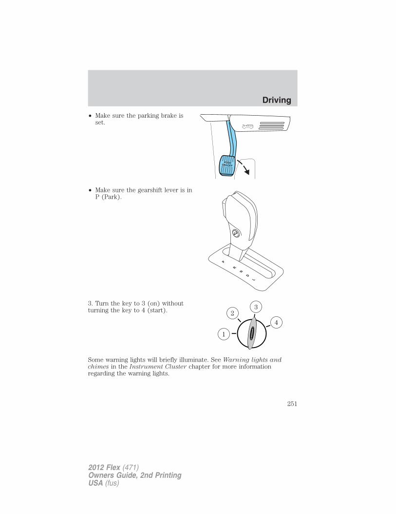
• Make sure the parking brake isset.
• Make sure the gearshift lever is inP (Park).
3. Turn the key to 3 (on) withoutturning the key to 4 (start).
Some warning lights will briefly illuminate. See Warning lights andchimes in the Instrument Cluster chapter for more informationregarding the warning lights.
Driving
251
2012 Flex (471)Owners Guide, 2nd PrintingUSA (fus)
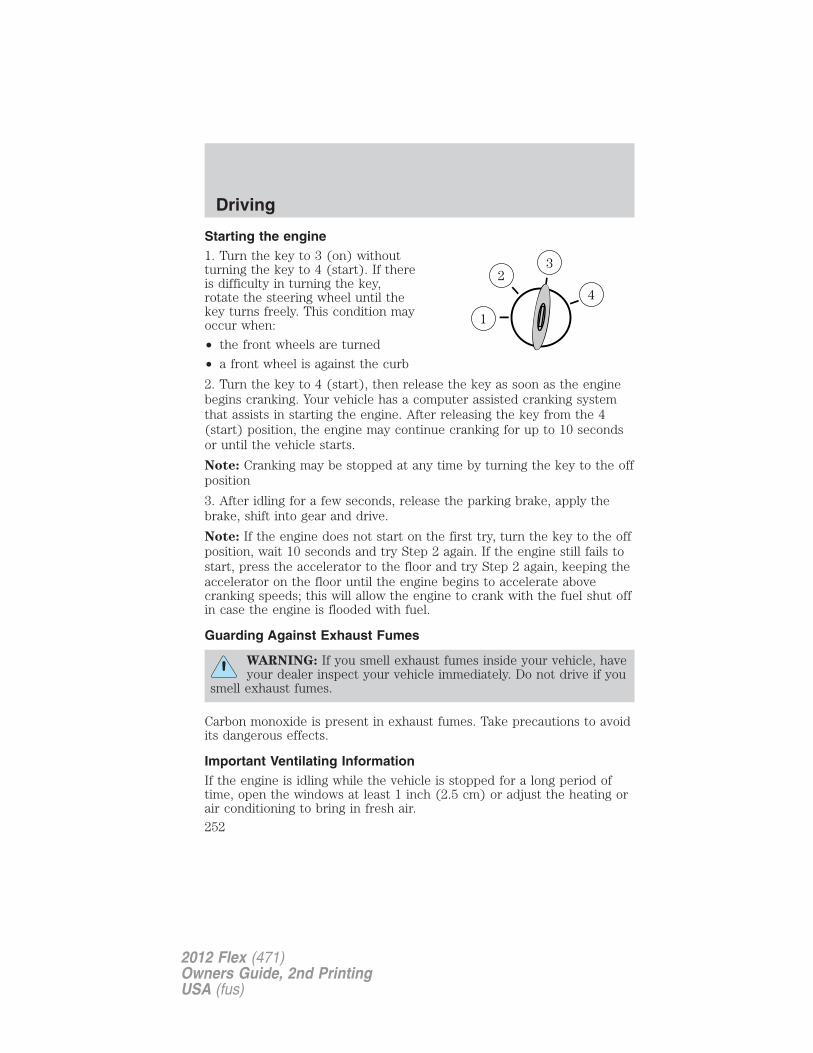
Starting the engine1. Turn the key to 3 (on) withoutturning the key to 4 (start). If thereis difficulty in turning the key,rotate the steering wheel until thekey turns freely. This condition mayoccur when:
• the front wheels are turned
• a front wheel is against the curb
2. Turn the key to 4 (start), then release the key as soon as the enginebegins cranking. Your vehicle has a computer assisted cranking systemthat assists in starting the engine. After releasing the key from the 4(start) position, the engine may continue cranking for up to 10 secondsor until the vehicle starts.
Note: Cranking may be stopped at any time by turning the key to the offposition
3. After idling for a few seconds, release the parking brake, apply thebrake, shift into gear and drive.
Note: If the engine does not start on the first try, turn the key to the offposition, wait 10 seconds and try Step 2 again. If the engine still fails tostart, press the accelerator to the floor and try Step 2 again, keeping theaccelerator on the floor until the engine begins to accelerate abovecranking speeds; this will allow the engine to crank with the fuel shut offin case the engine is flooded with fuel.
Guarding Against Exhaust Fumes
WARNING: If you smell exhaust fumes inside your vehicle, haveyour dealer inspect your vehicle immediately. Do not drive if you
smell exhaust fumes.
Carbon monoxide is present in exhaust fumes. Take precautions to avoidits dangerous effects.
Important Ventilating InformationIf the engine is idling while the vehicle is stopped for a long period oftime, open the windows at least 1 inch (2.5 cm) or adjust the heating orair conditioning to bring in fresh air.
Driving
252
2012 Flex (471)Owners Guide, 2nd PrintingUSA (fus)
ENGINE BLOCK HEATER (IF EQUIPPED)
WARNING: Failure to follow engine block heater instructionscould result in property damage or physical injury.
WARNING: To reduce the risk of electrical shock, do not useyour heater with ungrounded electrical systems or two-pronged
(cheater) adapters.
An engine block heater warms the engine coolant which aids in startingand allows the heater/defroster system to respond quickly. If your vehicleis equipped with this system, your equipment includes a heater elementwhich is installed in your engine block and a wire harness which allowsthe user to connect the system to a grounded 120 volt A/C electricalsource. The block heater system is most effective when outdoortemperatures reach below 0°F (-18°C).Prior to using the engine block heater, follow these recommendations forproper and safe operation:• For your safety, use an outdoor extension cord that is product
certified by Underwriter’s Laboratory (UL) or Canadian StandardsAssociation (CSA). Use only an extension cord that can be usedoutdoors, in cold temperatures, and is clearly marked “Suitable for Usewith Outdoor Appliances.” Never use an indoor extension cordoutdoors; it could result in an electric shock or fire hazard.
• Use a 16-gauge outdoor extension cord, minimum.• Use as short an extension cord as possible.• Do not use multiple extension cords. Instead, use one extension cord
which is long enough to reach from the engine block heater cord tothe outlet without stretching.
• Make certain that the extension cord is in excellent condition (notpatched or spliced). Store your extension cord indoors attemperatures above 32°F (0°C). Outdoor conditions can deteriorateextension cords over a period of time.
• To reduce the risk of electrical shock, do not use your heater withungrounded electrical systems or two pronged (cheater) adapters.Also ensure that the block heater, especially the cord, is in goodcondition before use.
• Make sure that when in operation, the extension cord plug/engineblock heater cord plug connection is free and clear of water in orderto prevent possible shock or fire.
Driving
253
2012 Flex (471)Owners Guide, 2nd PrintingUSA (fus)
• Be sure that areas where the vehicle is parked are clean and clear ofall combustibles such as petroleum products, dust, rags, paper andsimilar items.
• Be sure that the engine block heater, heater cord and extension cordare solidly connected. A poor connection can cause the cord tobecome very hot and may result in an electrical shock or fire. Be sureto check for heat anywhere in the electrical hookup once the systemhas been operating for approximately a half hour.
• Finally, have the engine block heater system checked during your falltune-up to be sure it’s in good working order.
How to use the engine block heater
Ensure the receptacle terminals are clean and dry prior to use. To cleanthem, use a dry cloth.
Depending on the type of factory installed equipment, your engine blockheater will use .4 to 1.0 kilowatt-hours of energy per hour of use. Yourfactory installed block heater system does not have a thermostat;however, maximum temperature is attained after approximately threehours of operation. Block heater operation longer than three hours willnot improve system performance and will unnecessarily use additionalelectricity.
Make sure system is unplugged and properly stowed before driving thevehicle. While not in use, make sure the protective cover seals theprongs of the engine block heater cord plug.
BRAKESOccasional brake noise is normal. If a metal-to-metal, continuous grindingor continuous squeal sound is present, the brake linings may be worn-outand should be inspected by an authorized dealer. If the vehicle hascontinuous vibration or shudder in the steering wheel while braking, thevehicle should be inspected by an authorized dealer.
Refer to Warning lights andchimes in the Instrument Clusterchapter for information on the brakesystem warning light.
P!BRAKE
Driving
254
2012 Flex (471)Owners Guide, 2nd PrintingUSA (fus)
Four-wheel anti-lock brake system (ABS)
Your vehicle is equipped with an anti-lock braking system (ABS). Thissystem helps you maintain steering control during emergency stops bykeeping the brakes from locking. Noise from the ABS pump motor andbrake pedal pulsation may be observed during ABS braking and thebrake pedal may suddenly travel a little farther as soon as ABS braking isdone and normal brake operation resumes. These are normalcharacteristics of the ABS and should be no reason for concern.
Using ABS
When hard braking is required, apply continuous force on the brakepedal. Do not pump the brake pedal since this will reduce theeffectiveness of the ABS and will increase your vehicle’s stoppingdistance. The ABS will be activated immediately, allowing you to retainsteering control during hard braking and on slippery surfaces. However,the ABS does not decrease stopping distance.
Brake assist
The brake assist system provides full braking force during panic brakingsituations. It detects a rapid application of the brake pedal and uses theABS system to achieve maximum braking pressure. Once a panic brakeapplication is detected, the system will remain activated as long as thebrake pedal is pressed or ABS is engaged. The system is deactivated byeither releasing the brake pedal or coming to a complete stop. When thesystem activates, noise from the ABS pump motor and brake pedalpulsation may be observed; this is normal.
ABS warning lampThe ABS lamp in the instrumentcluster momentarily illuminateswhen the ignition is turned on. Ifthe light does not illuminate duringstart up, remains on or flashes, theABS is disabled due to a malfunction and needs to be serviced.
Even when the ABS is disabled,normal braking is still effective. Ifyour BRAKE warning lampilluminates with the parking brakereleased, have your brake systemserviced immediately.
ABS
P!BRAKE
Driving
255
2012 Flex (471)Owners Guide, 2nd PrintingUSA (fus)
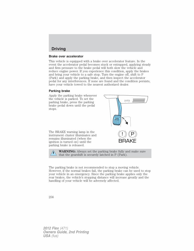
Brake over accelerator
This vehicle is equipped with a brake over accelerator feature. In theevent the accelerator pedal becomes stuck or entrapped, applying steadyand firm pressure to the brake pedal will both slow the vehicle andreduce engine power. If you experience this condition, apply the brakesand bring your vehicle to a safe stop. Turn the engine off, shift to P(Park) and apply the parking brake, and then inspect the acceleratorpedal for any interferences. If none are found and the condition persists,have your vehicle towed to the nearest authorized dealer.
Parking brakeApply the parking brake wheneverthe vehicle is parked. To set theparking brake, press the parkingbrake pedal down until the pedalstops.
The BRAKE warning lamp in theinstrument cluster illuminates andremains illuminated (when theignition is turned on) until theparking brake is released.
WARNING: Always set the parking brake fully and make surethat the gearshift is securely latched in P (Park).
The parking brake is not recommended to stop a moving vehicle.However, if the normal brakes fail, the parking brake can be used to stopyour vehicle in an emergency. Since the parking brake applies only therear brakes, the vehicle’s stopping distance will increase greatly and thehandling of your vehicle will be adversely affected.
P!BRAKE
Driving
256
2012 Flex (471)Owners Guide, 2nd PrintingUSA (fus)
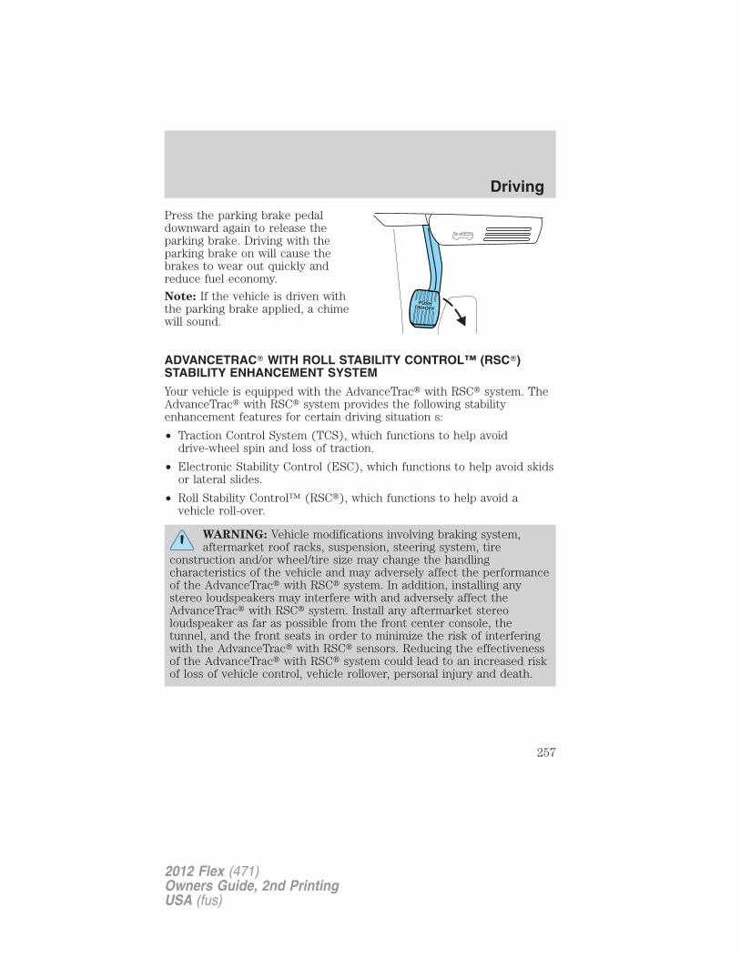
Press the parking brake pedaldownward again to release theparking brake. Driving with theparking brake on will cause thebrakes to wear out quickly andreduce fuel economy.
Note: If the vehicle is driven withthe parking brake applied, a chimewill sound.
ADVANCETRAC� WITH ROLL STABILITY CONTROL™ (RSC�)STABILITY ENHANCEMENT SYSTEM
Your vehicle is equipped with the AdvanceTrac� with RSC� system. TheAdvanceTrac� with RSC� system provides the following stabilityenhancement features for certain driving situation s:
• Traction Control System (TCS), which functions to help avoiddrive-wheel spin and loss of traction.
• Electronic Stability Control (ESC), which functions to help avoid skidsor lateral slides.
• Roll Stability Control™ (RSC�), which functions to help avoid avehicle roll-over.
WARNING: Vehicle modifications involving braking system,aftermarket roof racks, suspension, steering system, tire
construction and/or wheel/tire size may change the handlingcharacteristics of the vehicle and may adversely affect the performanceof the AdvanceTrac� with RSC� system. In addition, installing anystereo loudspeakers may interfere with and adversely affect theAdvanceTrac� with RSC� system. Install any aftermarket stereoloudspeaker as far as possible from the front center console, thetunnel, and the front seats in order to minimize the risk of interferingwith the AdvanceTrac� with RSC� sensors. Reducing the effectivenessof the AdvanceTrac� with RSC� system could lead to an increased riskof loss of vehicle control, vehicle rollover, personal injury and death.
Driving
257
2012 Flex (471)Owners Guide, 2nd PrintingUSA (fus)
WARNING: Remember that even advanced technology cannotdefy the laws of physics. It’s always possible to lose control of a
vehicle due to inappropriate driver input for the conditions. Aggressivedriving on any road condition can cause you to lose control of yourvehicle increasing the risk of personal injury or property damage.Activation of the AdvanceTrac� with RSC� system is an indication thatat least some of the tires have exceeded their ability to grip the road;this could reduce the operator’s ability to control the vehicle,potentially resulting in a loss of vehicle control, vehicle rollover,personal injury and death. If your AdvanceTrac� with RSC� systemactivates, SLOW DOWN.
WARNING: If a failure has been detected within theAdvanceTrac� with RSC� system, the stability control light will
illuminate steadily and you may hear a chime. If equipped with amessage center, the vehicle will also indicate a failure with the brakesystem. Have the system serviced by an authorized dealer immediately.
The AdvanceTrac� with RSC� system automatically enables each timethe engine is started. All features of the AdvanceTrac� with RSC� system(TCS, ESC, and RSC�) are active and monitor the vehicle from start-up.However, the system will only intervene if the driving situation requiresit.
The AdvanceTrac� with RSC�system includes an AdvanceTrac�button located on the center of theinstrument panel.The stability control light and the stability control off light in theinstrument cluster will illuminate temporarily during start-up as part of anormal system self-check. The stability control light may illuminate(flash) during certain driving situations which cause the AdvanceTrac�with RSC� system to operate. If the stability control light illuminatessteadily, have the system serviced by an authorized dealer immediately.The message center will also indicate a failure with the AdvanceTrac�with RSC� system.
Note: If the system cannot be turned off, refer to MyKey� in the Locksand Security chapter for more information.
When AdvanceTrac� with RSC� performs a normal system self-check,some drivers may notice a slight movement of the brake, and/or arumble, grunting, or grinding noise after startup and when driving off.
Driving
258
2012 Flex (471)Owners Guide, 2nd PrintingUSA (fus)
When an event occurs that activates AdvanceTrac� with RSC� you mayexperience the following:• A slight deceleration of the vehicle• The stability control light will flash.• If your foot is on the brake pedal, a vibration in the pedal.• If the driving condition is severe and your foot is not on the brake, the
brake pedal may move as the systems applies higher brake forces. Youmay also hear a whoosh of air from under the instrument panel duringthis severe condition.
• The brake pedal may feel stiffer than usual.Traction Control System (TCS)
The traction control system is a driver aid feature that helps your vehiclemaintain traction of the wheels, typically when driving on slippery and/orhilly road surfaces, by detecting and controlling wheel spin.Excessive wheel spin is controlled in two ways, which may workseparately or in tandem: engine traction control and brake tractioncontrol. Engine traction control works to limit drive-wheel spin bymomentarily reducing engine power. Brake traction control works to limitwheel spin by momentarily applying the brakes to the wheel that isslipping. Traction control is most active at low speeds.During TCS events, the stability control light in the instrument clusterwill flash.
If the TCS is activated excessively in a short period of time, the brakingportion of the system may become temporarily disabled to allow thebrakes to cool down. In this situation, TCS will use only engine powerreduction or transfer to help control the wheels from over-spinning.When the brakes have cooled down, the system will regain all features.Anti-lock braking, RSC�, and ESC will continue to function during thecool-down period.
The engine traction control and brake traction control system may bedeactivated in certain situations. See the Switching off traction controlsection following.
Electronic Stability Control (ESC)
Electronic stability control (ESC) may enhance your vehicle’s directionalstability during adverse maneuvers, for example when cornering severelyor avoiding objects in the roadway. ESC operates by applying brakes toone or more of the wheels individually and, if necessary, reducing enginepower if the system detects that the vehicle is about to skid or slidelaterally.
Driving
259
2012 Flex (471)Owners Guide, 2nd PrintingUSA (fus)
During ESC events, the stability control light in the instrument clusterwill flash.Certain adverse driving maneuvers may activate the ESC system, whichinclude but are not limited to:• Taking a turn too fast• Maneuvering quickly to avoid an accident, pedestrian or obstacle• Driving over a patch of ice or other slippery surfaces• Changing lanes on a snow-rutted road• Entering a snow-free road from a snow-covered side street, or vice
versa
• Entering a paved road from a gravel road, or vice versa
• Cornering while towing a heavily loaded trailer (refer to Trailertowing in the Tires, Wheels and Loading chapter).
Roll Stability Control™ (RSC�)
Roll Stability Control™ (RSC�) may help to maintain roll stability of thevehicle during adverse maneuvers. RSC� operates by detecting thevehicle’s roll motion and the rate at which it changes and by applying thebrakes to one or more wheels individually.
During an event that activates the RSC� system, the stability controllight in the instrument cluster will flash.
Certain adverse driving maneuvers may activate the RSC� system, whichinclude:
• Emergency lane-change
• Taking a turn too fast
• Quick maneuvering to avoid an accident, pedestrian or obstacle
Switching off traction control
If the vehicle is stuck in snow, mud or sand, and seems to lose enginepower, switching off the traction control feature of the AdvanceTrac�with RSC� system may be beneficial because the wheels are allowed tospin. This will restore full engine power and will enhance momentumthrough the obstacle.
To turn off the traction controlsystem, press the AdvanceTrac�button. Full features of the TCS canbe restored by pressing the tractioncontrol button again or by turning off and restarting the engine.
Driving
260
2012 Flex (471)Owners Guide, 2nd PrintingUSA (fus)
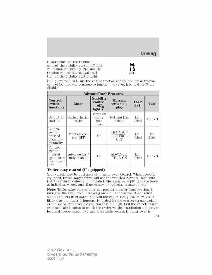
If you switch off the tractioncontrol, the stability control off lightwill illuminate steadily. Pressing thetraction control button again willturn off the stability control light.In R (Reverse), ABS and the engine traction control and brake tractioncontrol features will continue to function; however, ESC and RSC� aredisabled.
AdvanceTrac� Features
Controlswitchfunctions
Mode
Stabilitycontrol
off
light
Messagecenter dis-
play
ESC/RSC
TCS
Default atstart-up
System Initial-ization
Turns onduringbulb
check
Nothing Dis-played
En-abled Enabled
Controlswitchpressedonce mo-mentarily
Traction con-trol OFF On
TRACTIONCONTROL
OFF
En-abled
Dis-abled
Controlswitchpressedagain afterdeactiva-tion
AdvanceTrac�fully enabled Off ADVANCE-
TRAC ONEn-
abled Enabled
Trailer sway control (if equipped)
Your vehicle may be equipped with trailer sway control. When properlyequipped, trailer sway control will use the vehicle’s AdvanceTrac� withRSC� system to detect and mitigate trailer sway by applying brake forceat individual wheels and, if necessary, by reducing engine power.
Note: Trailer sway control does not prevent a trailer from swaying, itmitigates the sway from increasing once it has occurred. TSC cannotstop all trailers from swaying. If you are experiencing trailer sway it islikely that the trailer is improperly loaded for the correct tongue weightor the speed of the vehicle and trailer is too high. Pull the vehicle-trailerover to a safe location to check the trailer weight distribution and tongueload and reduce speed to a safe level while towing. If trailer sway is
OFF
Driving
261
2012 Flex (471)Owners Guide, 2nd PrintingUSA (fus)
experienced, SLOW DOWN. Always use caution when towing a trailerand follow the tongue weight recommendations. Refer to Trailer towingin the Tires, Wheels and Loading chapter for more information ontowing a trailer with your vehicle.During trailer sway control events, the stability control light in theinstrument cluster will flash momentarily. The cluster message centerwill also display TRAILER SWAY REDUCE SPEED. In some caseswhen trailer sway is detected, the vehicle speed is too high and may beat or above a speed at which trailer sway will grow continuously. Thismay cause the system to activate multiple times, causing a gradualreduction in speed.Disabling trailer sway control
Trailer sway control can be disabled during any key cycle. To disabletrailer sway control, refer to the Message center in the InstrumentCluster chapter. Note that regardless of chosen enable state, trailer swaycontrol will be re-enabled each new key cycle.
WARNING: Turning off trailer sway control increases the risk ofloss of vehicle control, serious injury, or death. Ford does not
recommend disabling this feature except in situations where speedreduction may be detrimental (e.g., hill climbing), the driver hassignificant trailer towing experience, and can control trailer sway andmaintain safe operation.
STEERING3.5L EcoBoost™ engine: Your vehicle is equipped with an ElectricPower Steering (EPS) system. There is no fluid reservoir to check or fill.If your vehicle loses electrical power while you are driving (or if theignition is turned off), you can steer the vehicle manually, but it takesmore effort. Extreme continuous steering may increase the effort it takesfor you to steer. This occurs to prevent internal overheating andpermanent damage to your steering system. If this should occur, you willneither lose the ability to steer the vehicle manually nor will it causepermanent damage. Typical steering and driving maneuvers will allow thesystem to cool and steering assist will return to normal.
The EPS system has diagnostic checks that continuously monitor theEPS system to ensure proper operation. When a system error isdetected, the following message SERVICE POWER STEERING, SERVICEPOWER STEERING NOW or POWER STEERING ASSIST FAULT maydisplay in the message center, refer to the Message center in theInstrument Cluster chapter for more information.
Driving
262
2012 Flex (471)Owners Guide, 2nd PrintingUSA (fus)
WARNING: The EPS system has diagnostics checks thatcontinuously monitor the EPS system to ensure proper operation
of the electronic system. When an electronic error is detected, themessage POWER STEERING ASSIST FAULT will be displayed in themessage center. If this happens, stop the vehicle in a safe place, andturn off the engine. After at least 10 seconds, reset the system byrestarting the engine, and watch the message center for POWERSTEERING ASSIST FAULT. If the message returns, or returns whiledriving, take the vehicle to your dealer to have it checked. With themessage displayed, the steering assist is turned off, making the vehicleharder to steer.
WARNING: If the message SERVICE POWER STEERING isdisplayed in the message center, the EPS system has detected a
problem with the system function. On the next key cycle the messageSERVICE POWER STEERING NOW will be displayed and steeringassist will be removed until the steering system is serviced. Have yourvehicle taken to the nearest dealer as soon as possible.
3.5L Duratec V6 engine: Your vehicle is equipped with a hydraulicsteering system.To help prevent damage to the power steering system, never hold thesteering wheel at its furthest turning points (until it stops) for more thana few seconds when the engine is running. If the power steering systembreaks down (or if the engine is turned off), you can steer the vehiclemanually, but it takes more effort.• Do not operate the vehicle with a low power steering pump fluid level
(below the MIN mark on the reservoir).• Some noise is normal during operation. If excessive, check for low
power steering pump fluid level before seeking service by yourauthorized dealer.
• Heavy or uneven steering efforts may be caused by low power steeringpump fluid level. Check for low power steering pump fluid level beforeseeking service by your authorized dealer.
• Do not fill the power steering pump reservoir above the MAX mark onthe reservoir, as this may result in leaks from the reservoir.
If the steering wanders or pulls equipped with either EPS or hydraulicsteering system, check for:
• an improperly inflated tire
Driving
263
2012 Flex (471)Owners Guide, 2nd PrintingUSA (fus)
• uneven tire wear
• loose or worn suspension components
• loose or worn steering components
• improper vehicle alignment
A high crown in the road or high crosswinds may also make the steeringseem to wander/pull.
WARNING: Obtain immediate service if a system error isdetected. You may not notice any difference in the feel of your
steering, but a serious condition may exist. Failure to do so may resultin loss of steering control.
BRAKE-SHIFT INTERLOCK
WARNING: Do not drive your vehicle until you verify that thebrakelamps are working.
WARNING: When doing this procedure, you will be taking thevehicle out of park which means the vehicle can roll freely. To
avoid unwanted vehicle movement, always fully set the parking brakeprior to doing this procedure. Use wheel chocks if appropriate.
WARNING: If the parking brake is fully released, but the brakewarning lamp remains illuminated, the brakes may not be
working properly. See your authorized dealer.
Note: See your authorized dealer as soon as possible if this procedure isused.
This vehicle is equipped with a brake-shift interlock feature that preventsthe gearshift lever from being moved from P (Park) when the ignition ison unless the brake pedal is pressed.
If you cannot move the gearshift lever out of P (Park) with the ignitionon and the brake pedal pressed, it is possible that a fuse has blown orthe vehicle’s brake lamps are not operating properly. Refer to the Fuseschapter.
Driving
264
2012 Flex (471)Owners Guide, 2nd PrintingUSA (fus)
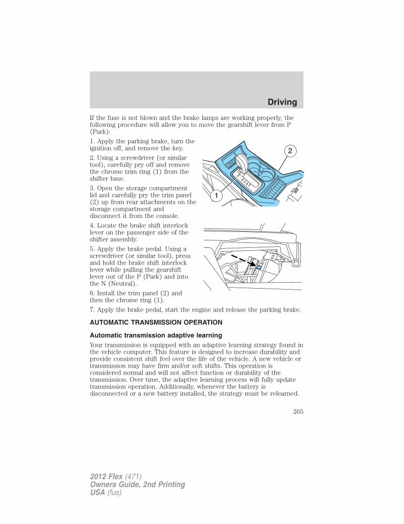
If the fuse is not blown and the brake lamps are working properly, thefollowing procedure will allow you to move the gearshift lever from P(Park):
1. Apply the parking brake, turn theignition off, and remove the key.
2. Using a screwdriver (or similartool), carefully pry off and removethe chrome trim ring (1) from theshifter base.
3. Open the storage compartmentlid and carefully pry the trim panel(2) up from rear attachments on thestorage compartment anddisconnect it from the console.
4. Locate the brake shift interlocklever on the passenger side of theshifter assembly.
5. Apply the brake pedal. Using ascrewdriver (or similar tool), pressand hold the brake shift interlocklever while pulling the gearshiftlever out of the P (Park) and intothe N (Neutral).
6. Install the trim panel (2) andthen the chrome ring (1).
7. Apply the brake pedal, start the engine and release the parking brake.
AUTOMATIC TRANSMISSION OPERATION
Automatic transmission adaptive learningYour transmission is equipped with an adaptive learning strategy found inthe vehicle computer. This feature is designed to increase durability andprovide consistent shift feel over the life of the vehicle. A new vehicle ortransmission may have firm and/or soft shifts. This operation isconsidered normal and will not affect function or durability of thetransmission. Over time, the adaptive learning process will fully updatetransmission operation. Additionally, whenever the battery isdisconnected or a new battery installed, the strategy must be relearned.
1
2
Driving
265
2012 Flex (471)Owners Guide, 2nd PrintingUSA (fus)
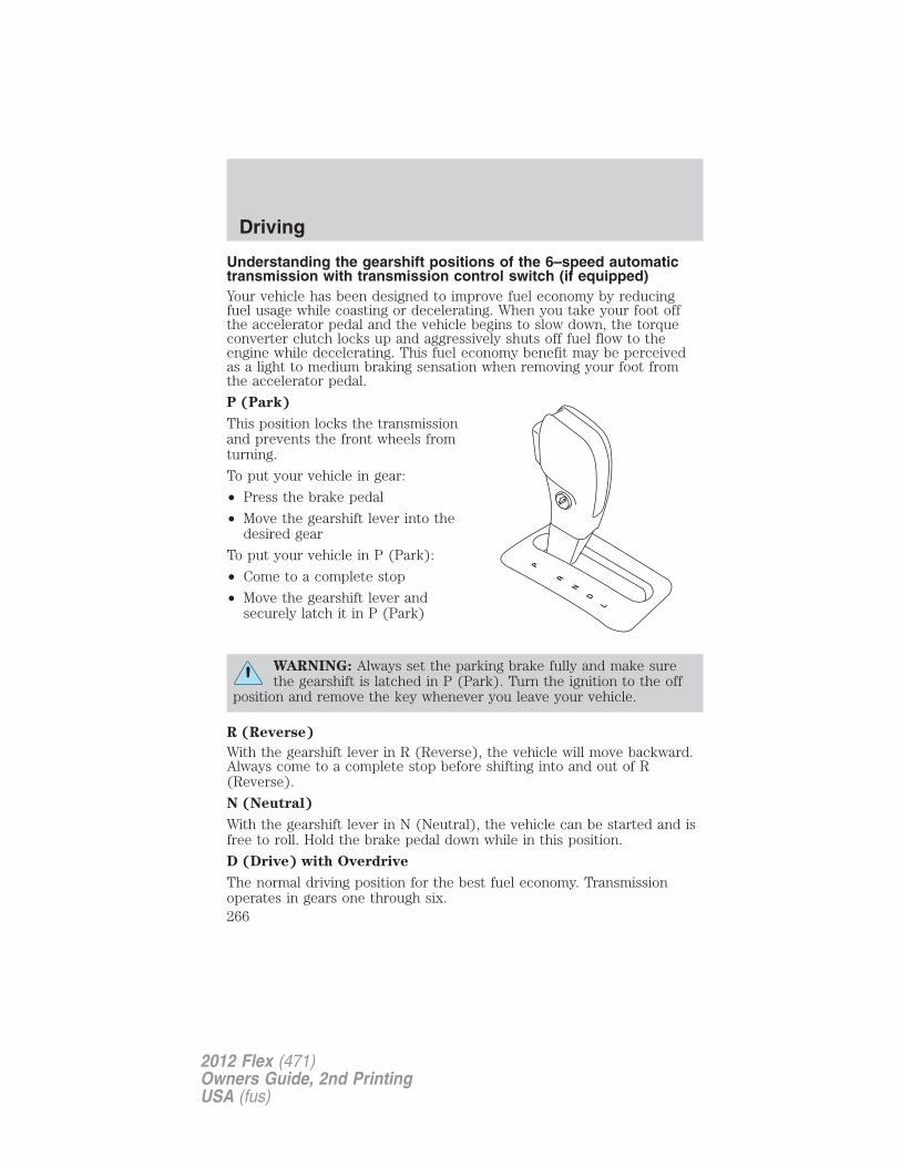
Understanding the gearshift positions of the 6–speed automatictransmission with transmission control switch (if equipped)Your vehicle has been designed to improve fuel economy by reducingfuel usage while coasting or decelerating. When you take your foot offthe accelerator pedal and the vehicle begins to slow down, the torqueconverter clutch locks up and aggressively shuts off fuel flow to theengine while decelerating. This fuel economy benefit may be perceivedas a light to medium braking sensation when removing your foot fromthe accelerator pedal.
P (Park)
This position locks the transmissionand prevents the front wheels fromturning.
To put your vehicle in gear:
• Press the brake pedal
• Move the gearshift lever into thedesired gear
To put your vehicle in P (Park):
• Come to a complete stop
• Move the gearshift lever andsecurely latch it in P (Park)
WARNING: Always set the parking brake fully and make surethe gearshift is latched in P (Park). Turn the ignition to the off
position and remove the key whenever you leave your vehicle.
R (Reverse)
With the gearshift lever in R (Reverse), the vehicle will move backward.Always come to a complete stop before shifting into and out of R(Reverse).
N (Neutral)
With the gearshift lever in N (Neutral), the vehicle can be started and isfree to roll. Hold the brake pedal down while in this position.
D (Drive) with Overdrive
The normal driving position for the best fuel economy. Transmissionoperates in gears one through six.
Driving
266
2012 Flex (471)Owners Guide, 2nd PrintingUSA (fus)
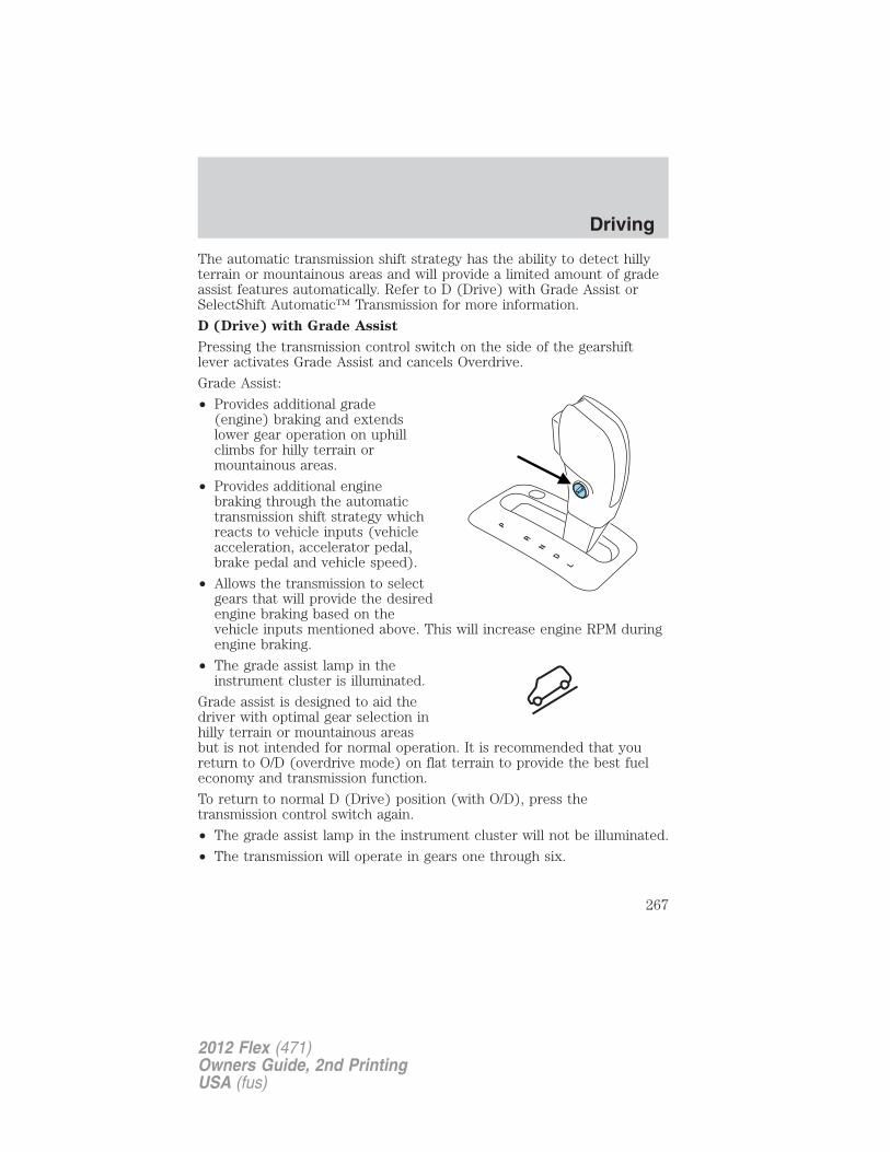
The automatic transmission shift strategy has the ability to detect hillyterrain or mountainous areas and will provide a limited amount of gradeassist features automatically. Refer to D (Drive) with Grade Assist orSelectShift Automatic™ Transmission for more information.
D (Drive) with Grade Assist
Pressing the transmission control switch on the side of the gearshiftlever activates Grade Assist and cancels Overdrive.
Grade Assist:
• Provides additional grade(engine) braking and extendslower gear operation on uphillclimbs for hilly terrain ormountainous areas.
• Provides additional enginebraking through the automatictransmission shift strategy whichreacts to vehicle inputs (vehicleacceleration, accelerator pedal,brake pedal and vehicle speed).
• Allows the transmission to selectgears that will provide the desiredengine braking based on thevehicle inputs mentioned above. This will increase engine RPM duringengine braking.
• The grade assist lamp in theinstrument cluster is illuminated.
Grade assist is designed to aid thedriver with optimal gear selection inhilly terrain or mountainous areasbut is not intended for normal operation. It is recommended that youreturn to O/D (overdrive mode) on flat terrain to provide the best fueleconomy and transmission function.
To return to normal D (Drive) position (with O/D), press thetransmission control switch again.
• The grade assist lamp in the instrument cluster will not be illuminated.
• The transmission will operate in gears one through six.
Driving
267
2012 Flex (471)Owners Guide, 2nd PrintingUSA (fus)
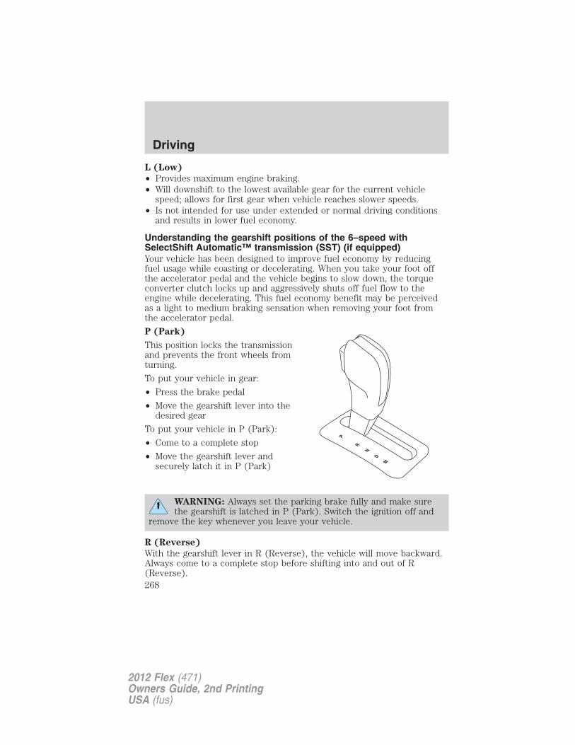
L (Low)
• Provides maximum engine braking.• Will downshift to the lowest available gear for the current vehicle
speed; allows for first gear when vehicle reaches slower speeds.• Is not intended for use under extended or normal driving conditions
and results in lower fuel economy.
Understanding the gearshift positions of the 6–speed withSelectShift Automatic™ transmission (SST) (if equipped)Your vehicle has been designed to improve fuel economy by reducingfuel usage while coasting or decelerating. When you take your foot offthe accelerator pedal and the vehicle begins to slow down, the torqueconverter clutch locks up and aggressively shuts off fuel flow to theengine while decelerating. This fuel economy benefit may be perceivedas a light to medium braking sensation when removing your foot fromthe accelerator pedal.
P (Park)
This position locks the transmissionand prevents the front wheels fromturning.
To put your vehicle in gear:
• Press the brake pedal
• Move the gearshift lever into thedesired gear
To put your vehicle in P (Park):
• Come to a complete stop
• Move the gearshift lever andsecurely latch it in P (Park)
WARNING: Always set the parking brake fully and make surethe gearshift is latched in P (Park). Switch the ignition off and
remove the key whenever you leave your vehicle.
R (Reverse)
With the gearshift lever in R (Reverse), the vehicle will move backward.Always come to a complete stop before shifting into and out of R(Reverse).
Driving
268
2012 Flex (471)Owners Guide, 2nd PrintingUSA (fus)
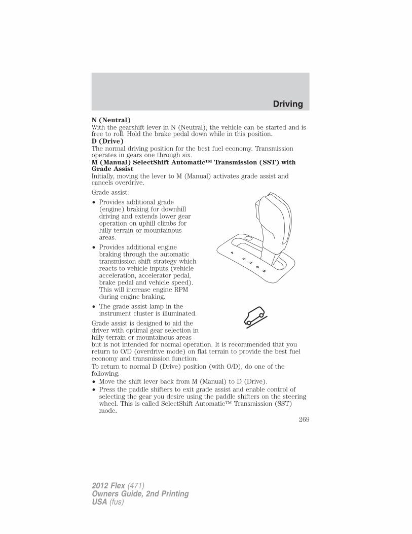
N (Neutral)
With the gearshift lever in N (Neutral), the vehicle can be started and isfree to roll. Hold the brake pedal down while in this position.D (Drive)
The normal driving position for the best fuel economy. Transmissionoperates in gears one through six.M (Manual) SelectShift Automatic™ Transmission (SST) withGrade Assist
Initially, moving the lever to M (Manual) activates grade assist andcancels overdrive.
Grade assist:
• Provides additional grade(engine) braking for downhilldriving and extends lower gearoperation on uphill climbs forhilly terrain or mountainousareas.
• Provides additional enginebraking through the automatictransmission shift strategy whichreacts to vehicle inputs (vehicleacceleration, accelerator pedal,brake pedal and vehicle speed).This will increase engine RPMduring engine braking.
• The grade assist lamp in theinstrument cluster is illuminated.
Grade assist is designed to aid thedriver with optimal gear selection inhilly terrain or mountainous areasbut is not intended for normal operation. It is recommended that youreturn to O/D (overdrive mode) on flat terrain to provide the best fueleconomy and transmission function.To return to normal D (Drive) position (with O/D), do one of thefollowing:• Move the shift lever back from M (Manual) to D (Drive).• Press the paddle shifters to exit grade assist and enable control of
selecting the gear you desire using the paddle shifters on the steeringwheel. This is called SelectShift Automatic™ Transmission (SST)mode.
Driving
269
2012 Flex (471)Owners Guide, 2nd PrintingUSA (fus)
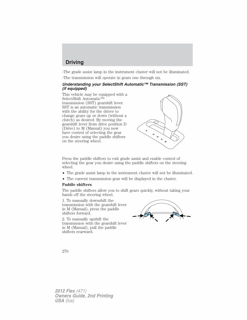
-The grade assist lamp in the instrument cluster will not be illuminated.
-The transmission will operate in gears one through six.
Understanding your SelectShift Automatic™ Transmission (SST)(if equipped)This vehicle may be equipped with aSelectShift Automatic™transmission (SST) gearshift lever.SST is an automatic transmissionwith the ability for the driver tochange gears up or down (without aclutch) as desired. By moving thegearshift lever from drive position D(Drive) to M (Manual) you nowhave control of selecting the gearyou desire using the paddle shifterson the steering wheel.
Press the paddle shifters to exit grade assist and enable control ofselecting the gear you desire using the paddle shifters on the steeringwheel.
• The grade assist lamp in the instrument cluster will not be illuminated.
• The current transmission gear will be displayed in the cluster.
Paddle shifters
The paddle shifters allow you to shift gears quickly, without taking yourhands off the steering wheel.
1. To manually downshift thetransmission with the gearshift leverin M (Manual), press the paddleshifters forward.
2. To manually upshift thetransmission with the gearshift leverin M (Manual), pull the paddleshifters rearward.
Driving
270
2012 Flex (471)Owners Guide, 2nd PrintingUSA (fus)
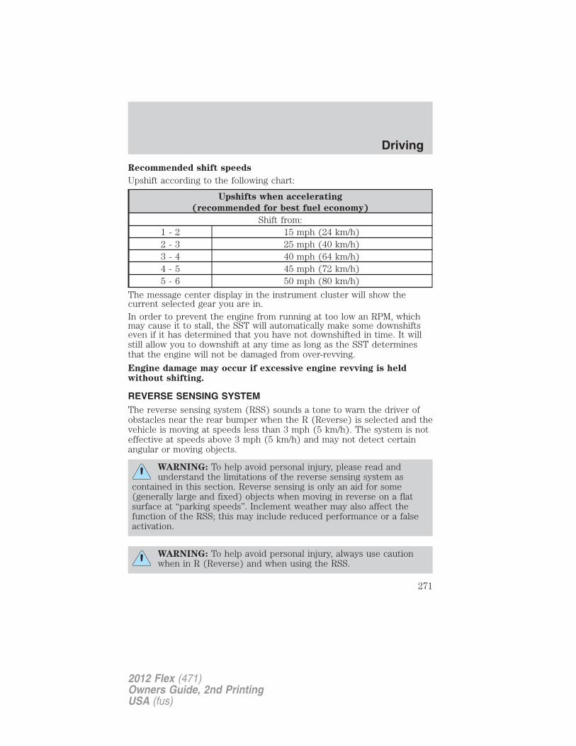
Recommended shift speeds
Upshift according to the following chart:
Upshifts when accelerating
(recommended for best fuel economy)
Shift from:1 - 2 15 mph (24 km/h)2 - 3 25 mph (40 km/h)3 - 4 40 mph (64 km/h)4 - 5 45 mph (72 km/h)5 - 6 50 mph (80 km/h)
The message center display in the instrument cluster will show thecurrent selected gear you are in.In order to prevent the engine from running at too low an RPM, whichmay cause it to stall, the SST will automatically make some downshiftseven if it has determined that you have not downshifted in time. It willstill allow you to downshift at any time as long as the SST determinesthat the engine will not be damaged from over-revving.
Engine damage may occur if excessive engine revving is heldwithout shifting.
REVERSE SENSING SYSTEMThe reverse sensing system (RSS) sounds a tone to warn the driver ofobstacles near the rear bumper when the R (Reverse) is selected and thevehicle is moving at speeds less than 3 mph (5 km/h). The system is noteffective at speeds above 3 mph (5 km/h) and may not detect certainangular or moving objects.
WARNING: To help avoid personal injury, please read andunderstand the limitations of the reverse sensing system as
contained in this section. Reverse sensing is only an aid for some(generally large and fixed) objects when moving in reverse on a flatsurface at “parking speeds”. Inclement weather may also affect thefunction of the RSS; this may include reduced performance or a falseactivation.
WARNING: To help avoid personal injury, always use cautionwhen in R (Reverse) and when using the RSS.
Driving
271
2012 Flex (471)Owners Guide, 2nd PrintingUSA (fus)
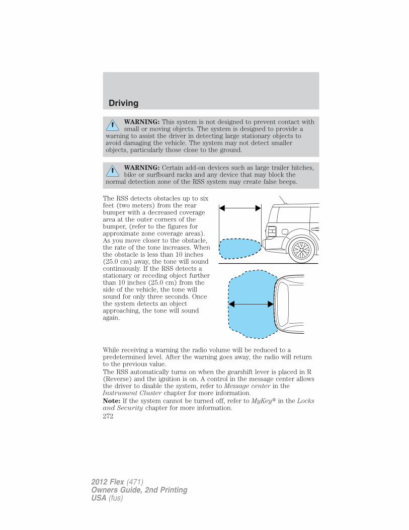
WARNING: This system is not designed to prevent contact withsmall or moving objects. The system is designed to provide a
warning to assist the driver in detecting large stationary objects toavoid damaging the vehicle. The system may not detect smallerobjects, particularly those close to the ground.
WARNING: Certain add-on devices such as large trailer hitches,bike or surfboard racks and any device that may block the
normal detection zone of the RSS system may create false beeps.
The RSS detects obstacles up to sixfeet (two meters) from the rearbumper with a decreased coveragearea at the outer corners of thebumper, (refer to the figures forapproximate zone coverage areas).As you move closer to the obstacle,the rate of the tone increases. Whenthe obstacle is less than 10 inches(25.0 cm) away, the tone will soundcontinuously. If the RSS detects astationary or receding object furtherthan 10 inches (25.0 cm) from theside of the vehicle, the tone willsound for only three seconds. Oncethe system detects an objectapproaching, the tone will soundagain.
While receiving a warning the radio volume will be reduced to apredetermined level. After the warning goes away, the radio will returnto the previous value.The RSS automatically turns on when the gearshift lever is placed in R(Reverse) and the ignition is on. A control in the message center allowsthe driver to disable the system, refer to Message center in theInstrument Cluster chapter for more information.Note: If the system cannot be turned off, refer to MyKey� in the Locksand Security chapter for more information.
Driving
272
2012 Flex (471)Owners Guide, 2nd PrintingUSA (fus)
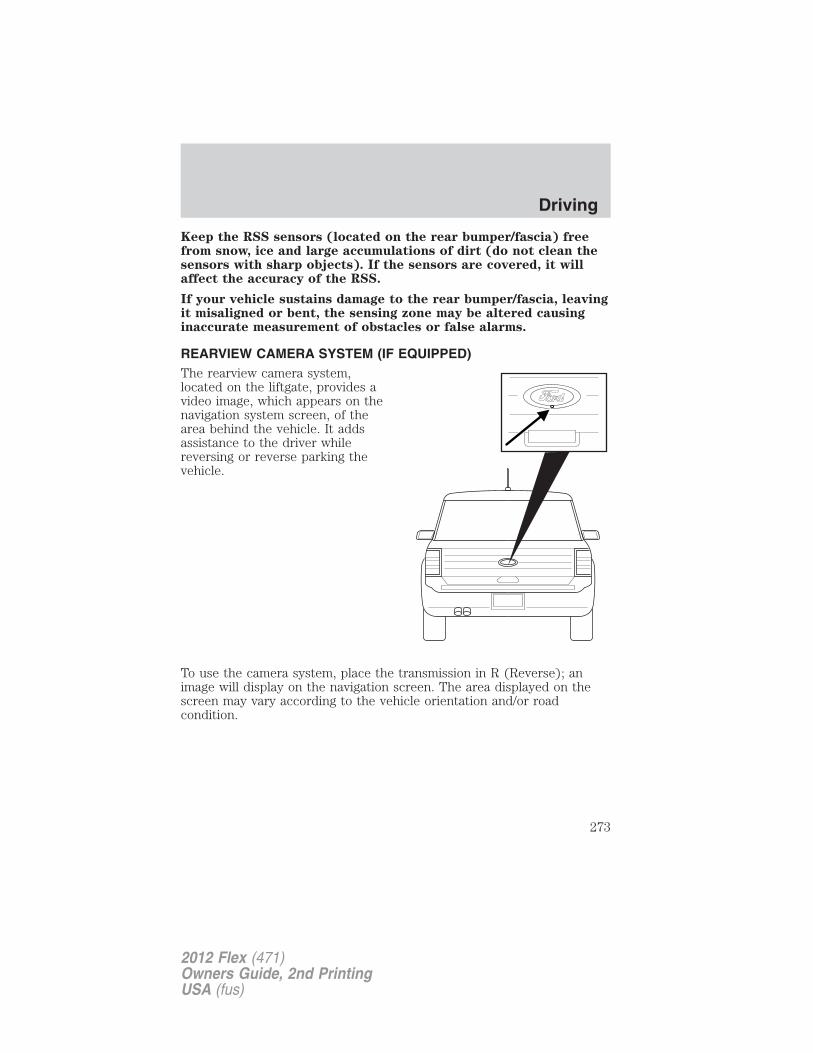
Keep the RSS sensors (located on the rear bumper/fascia) freefrom snow, ice and large accumulations of dirt (do not clean thesensors with sharp objects). If the sensors are covered, it willaffect the accuracy of the RSS.
If your vehicle sustains damage to the rear bumper/fascia, leavingit misaligned or bent, the sensing zone may be altered causinginaccurate measurement of obstacles or false alarms.
REARVIEW CAMERA SYSTEM (IF EQUIPPED)The rearview camera system,located on the liftgate, provides avideo image, which appears on thenavigation system screen, of thearea behind the vehicle. It addsassistance to the driver whilereversing or reverse parking thevehicle.
To use the camera system, place the transmission in R (Reverse); animage will display on the navigation screen. The area displayed on thescreen may vary according to the vehicle orientation and/or roadcondition.
Driving
273
2012 Flex (471)Owners Guide, 2nd PrintingUSA (fus)
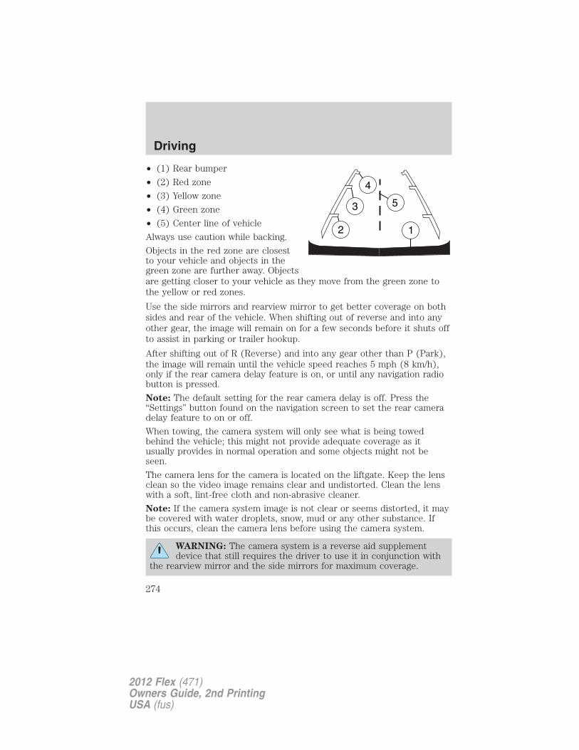
• (1) Rear bumper
• (2) Red zone
• (3) Yellow zone
• (4) Green zone
• (5) Center line of vehicle
Always use caution while backing.
Objects in the red zone are closestto your vehicle and objects in thegreen zone are further away. Objectsare getting closer to your vehicle as they move from the green zone tothe yellow or red zones.
Use the side mirrors and rearview mirror to get better coverage on bothsides and rear of the vehicle. When shifting out of reverse and into anyother gear, the image will remain on for a few seconds before it shuts offto assist in parking or trailer hookup.
After shifting out of R (Reverse) and into any gear other than P (Park),the image will remain until the vehicle speed reaches 5 mph (8 km/h),only if the rear camera delay feature is on, or until any navigation radiobutton is pressed.
Note: The default setting for the rear camera delay is off. Press the“Settings” button found on the navigation screen to set the rear cameradelay feature to on or off.
When towing, the camera system will only see what is being towedbehind the vehicle; this might not provide adequate coverage as itusually provides in normal operation and some objects might not beseen.
The camera lens for the camera is located on the liftgate. Keep the lensclean so the video image remains clear and undistorted. Clean the lenswith a soft, lint-free cloth and non-abrasive cleaner.
Note: If the camera system image is not clear or seems distorted, it maybe covered with water droplets, snow, mud or any other substance. Ifthis occurs, clean the camera lens before using the camera system.
WARNING: The camera system is a reverse aid supplementdevice that still requires the driver to use it in conjunction with
the rearview mirror and the side mirrors for maximum coverage.
Driving
274
2012 Flex (471)Owners Guide, 2nd PrintingUSA (fus)
WARNING: Objects that are close to either corner of thebumper or under the bumper, might not be seen on the screen
due to the limited coverage of the camera system.
WARNING: Backup as slow as possible since higher speedsmight limit your reaction time to stop the vehicle.
WARNING: Do not use the camera system with the liftgateopen.
If the back end of the vehicle is hit or damaged, then check with yourauthorized dealer to have your rear video system checked for propercoverage and operation.
Night time and dark area use
At night time or in dark areas, the camera system relies on the reverselamp lighting to produce an image. Therefore it is necessary that bothreverse lamps are operating in order to get a clear image in the dark. Ifeither of the lamps are not operating, stop using the camera system, atleast in the dark, until the lamp(s) are replaced and functioning.
Servicing
• If the image comes on while the vehicle is not in R (Reverse), havethe system inspected by your authorized dealer.
• If the image is not clear, then check if there is anything covering thelens such as dirt, mud, ice, snow, etc. If the image is still not clearafter cleaning, have your system inspected by your authorized dealer.
ACTIVE PARK ASSIST (APA) (IF EQUIPPED)Active park assist (APA) will detect an available parallel parking spaceand automatically steer the vehicle into the space (hands-free) while youcontrol the accelerator, gearshift and brakes. The system will visuallyand/or audibly instruct the driver to park the vehicle.
WARNING: This system is designed to be a supplementary parkaid. It may not work in all conditions and is not intended to
replace the driver’s attention and judgment. The driver is responsiblefor avoiding hazards and maintaining a safe distance and speed, evenwhen the APA is in use.
Driving
275
2012 Flex (471)Owners Guide, 2nd PrintingUSA (fus)
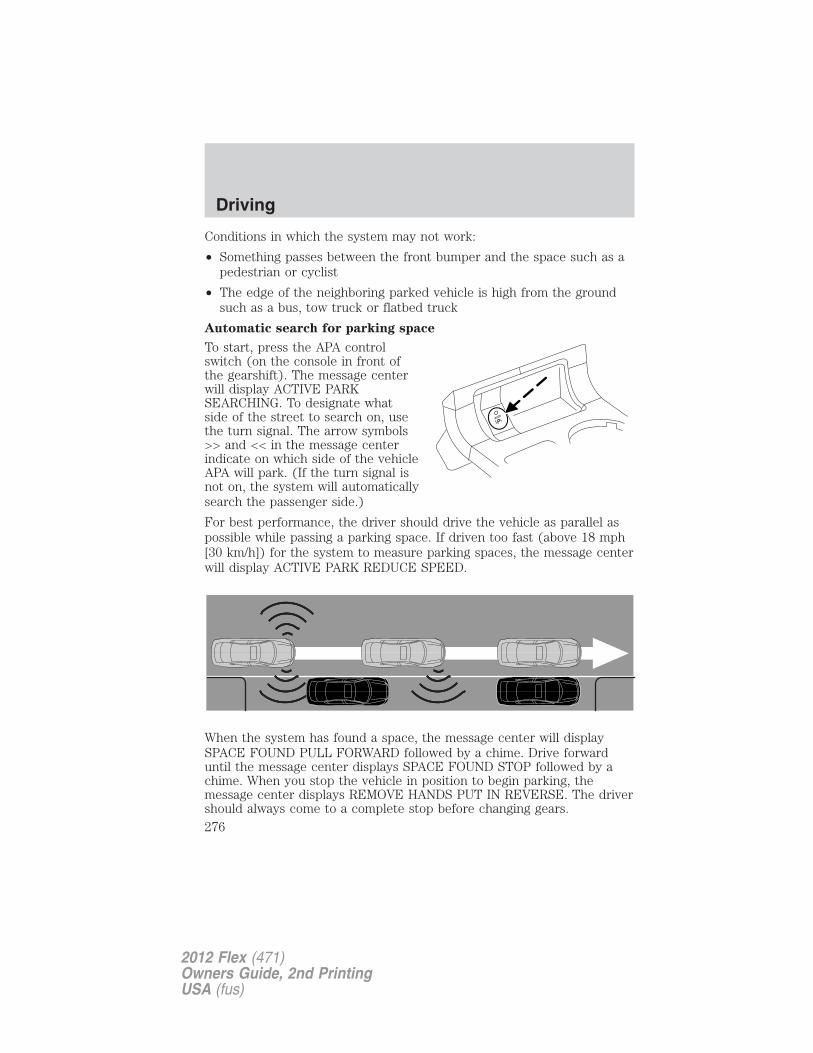
Conditions in which the system may not work:
• Something passes between the front bumper and the space such as apedestrian or cyclist
• The edge of the neighboring parked vehicle is high from the groundsuch as a bus, tow truck or flatbed truck
Automatic search for parking space
To start, press the APA controlswitch (on the console in front ofthe gearshift). The message centerwill display ACTIVE PARKSEARCHING. To designate whatside of the street to search on, usethe turn signal. The arrow symbols>> and << in the message centerindicate on which side of the vehicleAPA will park. (If the turn signal isnot on, the system will automaticallysearch the passenger side.)
For best performance, the driver should drive the vehicle as parallel aspossible while passing a parking space. If driven too fast (above 18 mph[30 km/h]) for the system to measure parking spaces, the message centerwill display ACTIVE PARK REDUCE SPEED.
When the system has found a space, the message center will displaySPACE FOUND PULL FORWARD followed by a chime. Drive forwarduntil the message center displays SPACE FOUND STOP followed by achime. When you stop the vehicle in position to begin parking, themessage center displays REMOVE HANDS PUT IN REVERSE. The drivershould always come to a complete stop before changing gears.
Driving
276
2012 Flex (471)Owners Guide, 2nd PrintingUSA (fus)
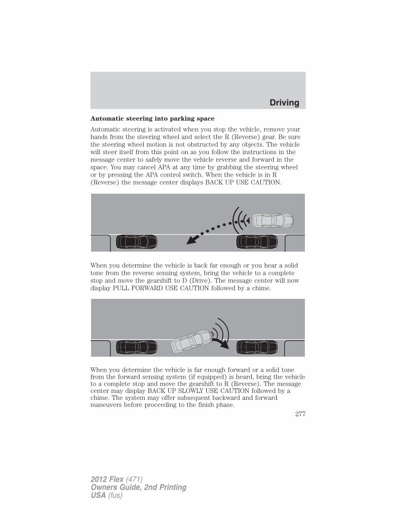
Automatic steering into parking space
Automatic steering is activated when you stop the vehicle, remove yourhands from the steering wheel and select the R (Reverse) gear. Be surethe steering wheel motion is not obstructed by any objects. The vehiclewill steer itself from this point on as you follow the instructions in themessage center to safely move the vehicle reverse and forward in thespace. You may cancel APA at any time by grabbing the steering wheelor by pressing the APA control switch. When the vehicle is in R(Reverse) the message center displays BACK UP USE CAUTION.
When you determine the vehicle is back far enough or you hear a solidtone from the reverse sensing system, bring the vehicle to a completestop and move the gearshift to D (Drive). The message center will nowdisplay PULL FORWARD USE CAUTION followed by a chime.
When you determine the vehicle is far enough forward or a solid tonefrom the forward sensing system (if equipped) is heard, bring the vehicleto a complete stop and move the gearshift to R (Reverse). The messagecenter may display BACK UP SLOWLY USE CAUTION followed by achime. The system may offer subsequent backward and forwardmaneuvers before proceeding to the finish phase.
Driving
277
2012 Flex (471)Owners Guide, 2nd PrintingUSA (fus)
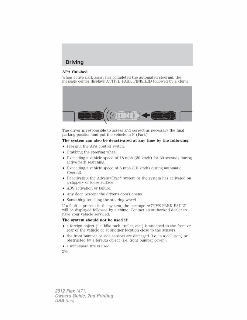
APA finished
When active park assist has completed the automated steering, themessage center displays ACTIVE PARK FINISHED followed by a chime.
The driver is responsible to assess and correct as necessary the finalparking position and put the vehicle in P (Park).
The system can also be deactivated at any time by the following:
• Pressing the APA control switch.
• Grabbing the steering wheel.
• Exceeding a vehicle speed of 18 mph (30 km/h) for 30 seconds duringactive park searching.
• Exceeding a vehicle speed of 6 mph (10 km/h) during automaticsteering.
• Deactivating the AdvanceTrac� system or the system has activated ona slippery or loose surface.
• ABS activation or failure.
• Any door (except the driver’s door) opens.
• Something touching the steering wheel.
If a fault is present in the system, the message ACTIVE PARK FAULTwill be displayed followed by a chime. Contact an authorized dealer tohave your vehicle serviced.
The system should not be used if:
• a foreign object (i.e. bike rack, trailer, etc.) is attached to the front orrear of the vehicle or at another location close to the sensors.
• the front bumper or side sensors are damaged (i.e. in a collision) orobstructed by a foreign object (i.e. front bumper cover).
• a mini-spare tire is used.
Driving
278
2012 Flex (471)Owners Guide, 2nd PrintingUSA (fus)
Troubleshooting
Why isn’t APA searching for a parking space?
• You may have deactivated the AdvanceTrac� system.• One of the doors (except the driver’s door) may not be securely
closed.Why doesn’t APA offer a particular parking space?
• Something may be contacting the front bumper or side sensors. Clearany material stuck to the sensors.
• There may not be enough room to maneuver the vehicle into thespace. Remember, there needs to be enough space on the oppositeside of the vehicle to allow the front of the vehicle to swing out as youback into the space.
• The vehicle is not driven close enough to the parking space, less than60 inches (1.5 m) from neighboring parked vehicles.
• The vehicle is driven too close to the side objects (e.g. less than16 inches [41 cm] from neighboring parked vehicles).
• You may be driving in R (Reverse). APA can only look for a parkingspace while moving forward.
Why doesn’t APA position the vehicle where I want in the space?
• The driver allows the vehicle to roll in the opposite direction of thetransmission (such as rolling forward when R (Reverse) gear isselected.
• You may be driving in R (Reverse). APA can only look for a parkingspace while moving forward.
• There may be an irregular curb along the parking space. APA mightnot be able to align the vehicle to curbs that are damaged, veryshallow or covered with material such as debris, leaves, snow, or tarps.
• The vehicles or objects bordering the space may not be positionedappropriately.
• The vehicle was pulled further up from the parking space than usualwhile driving by the space. APA performs best when you drive thesame distance past the entire length of the parking space.
• The tires may not be installed and maintained correctly. For example,one or more tires may not be inflated correctly, may not be of thesame size, or may not be authorized for use on this vehicle.
• The vehicle had a repair or alteration that is not authorized by themanufacturer.
Driving
279
2012 Flex (471)Owners Guide, 2nd PrintingUSA (fus)
• One of the parked vehicles has a high altitude attachment (i.e. saltsprayer, snow plow, moving truck high bed, etc.) High altitudeattachments may not be detected by the system.
• The parking space length or parked objects position have changedafter the vehicle has passed the parking space.
• The temperature around your vehicle changes quickly, such as drivingfrom a heated garage into the cold, or after leaving a car wash. As aresult, the outside air temperature displayed in the vehicle may not beclose enough to the actual temperature. APA relies on correctlysensing the temperature outside for precisely positioning the vehicle.
ALL-WHEEL DRIVE (AWD) SYSTEM (IF EQUIPPED)Your vehicle may be equipped with a full-time all-wheel drive (AWD)system. The AWD system is an active system, meaning it not onlyresponds to wheel slip between the front and rear axles but also has theability to anticipate wheel slip and transfer torque to the rear wheelsbefore slip occurs. The AWD system is active all the time and requires noinput from the operator.
All components of the AWD system are sealed for life and require nomaintenance.
Note: When an AWD system fault is present, the warning CHECK AWDwill display in the message center. The AWD system is not functioningcorrectly and defaulted to front-wheel drive. When this warning isdisplayed, have your vehicle serviced at an authorized dealer.
If your vehicle is equipped with AWD, a spare tire of a different sizeother than the tire provided should never be used. If the spare tire isinstalled, the AWD system may disable automatically and enterfront-wheel drive only mode to protect driveline components. Thiscondition may be indicated by an AWD OFF message in the messagecenter (see Message center section in the Instrument Cluster chapterfor more information). If there is an AWD OFF message in the messagecenter from using the spare tire, this indicator should turn off afterreinstalling the repaired or replaced normal road tire and driving a shortdistance. It is recommended to reinstall the repaired or replaced roadtire as soon as possible. Major dissimilar tire sizes between the front andrear axles could cause the AWD system to stop functioning and defaultto front-wheel drive or damage the AWD system.
Note: The AWD OFF message may also be displayed in the messagecenter if the AWD system has overheated and defaulted to front-wheeldrive. This condition may occur if the vehicle was operated in extreme
Driving
280
2012 Flex (471)Owners Guide, 2nd PrintingUSA (fus)
conditions with excessive wheel slip, such as deep sand. To resumenormal AWD function as soon as possible, stop the vehicle in a safelocation and allow it to idle. The AWD OFF message will turn off whenthe system cools and normal AWD function returns.Note: Your AWD vehicle is not intended for off-road use. The AWDfeature gives your vehicle some limited off-road capabilities in whichdriving surfaces are relatively level, obstruction-free and otherwise similarto normal on-road driving conditions. Operating your vehicle under otherthan those conditions could subject the vehicle to excessive stress whichmight result in damage which is not covered under your warranty.
Driving on slippery surfaces with AWD vehiclesAWD vehicles are specially equipped for driving on sand, snow, mud andrough roads and have operating characteristics that are somewhatdifferent from conventional vehicles, both on and off the highway.When driving at slow speeds off-highway under high outsidetemperatures, use a low gear when possible. Lower gear operation willmaximize the engine and transmission cooling capability.
Under severe operating conditions, the A/C may cycle on and off toprotect overheating of the engine.
Basic operating principles• Drive slower in strong crosswinds which can affect the normal steering
characteristics of your vehicle.
• Be extremely careful when driving on pavement made slippery byloose sand, water, gravel, snow or ice.
If your vehicle goes off the edge of the pavement• If your vehicle goes off the edge of the pavement, slow down, but
avoid severe brake application, ease the vehicle back onto thepavement only after reducing your speed. Do not turn the steeringwheel too sharply while returning to the road surface.
• It may be safer to stay on the apron or shoulder of the road and slowdown gradually before returning to the pavement. You may losecontrol if you do not slow down or if you turn the steering wheel toosharply or abruptly.
• It often may be less risky to strike small objects, such as highwayreflectors, with minor damage to your vehicle rather than attempt asudden return to the pavement which could cause the vehicle to slidesideways out of control or rollover. Remember, your safety and thesafety of others should be your primary concern.
Driving
281
2012 Flex (471)Owners Guide, 2nd PrintingUSA (fus)
If your vehicle gets stuck
WARNING: Always set the parking brake fully and make surethe gearshift is latched in P (Park). Switch the ignition off and
remove the key whenever you leave your vehicle.
WARNING: If the parking brake is fully released, but the brakewarning lamp remains illuminated, the brakes may not be
working properly. See your authorized dealer.
WARNING: Do not spin the wheels at over 35 mph (56 km/h).The tires may fail and injure a passenger or bystander.
If your vehicle gets stuck in mud or snow it may be rocked out byshifting between forward and reverse gears, stopping between shifts, in asteady pattern. Press lightly on the accelerator in each gear.
Your vehicle is equipped with traction control. It may be beneficial todisengage the traction control system while attempting to rock thevehicle.
Note: Do not rock the vehicle if the engine is not at normal operatingtemperature or damage to the transmission may occur.
Note: Do not rock the vehicle for more than a few minutes or damage tothe transmission and tires may occur or the engine may overheat.
Emergency maneuvers
• In an unavoidable emergency situation where a sudden sharp turnmust be made, remember to avoid “over-driving” your vehicle (i.e.,turn the steering wheel only as rapidly and as far as required to avoidthe emergency). Excessive steering will result in less vehicle control,not more. Additionally, smooth variations of the accelerator and/orbrake pedal pressure should be utilized if changes in vehicle speed arecalled for. Avoid abrupt steering, acceleration or braking which couldresult in an increased risk of loss of vehicle control, vehicle rolloverand/or personal injury. Use all available road surface to return thevehicle to a safe direction of travel.
• In the event of an emergency stop, avoid skidding the tires and do notattempt any sharp steering wheel movements.
Driving
282
2012 Flex (471)Owners Guide, 2nd PrintingUSA (fus)
• If the vehicle goes from one type of surface to another (i.e., fromconcrete to gravel) there will be a change in the way the vehicleresponds to a maneuver (steering, acceleration or braking). Again,avoid these abrupt inputs.
AWD systems (if equipped)AWD uses all four wheels to power the vehicle. This increases traction,enabling you to drive over terrain and road conditions that aconventional two-wheel drive vehicle cannot.
SandWhen driving over sand, try to keep all four wheels on the most solidarea of the trail. Avoid reducing the tire pressures but shift to a lowergear and drive steadily through the terrain. Apply the accelerator slowlyand avoid spinning the wheels.When driving at slow speeds in deep sand under high outsidetemperatures, use a low gear when possible. Lower gear operation willmaximize the engine and transmission cooling capability.Under severe operating conditions, the A/C may cycle on and off toprotect overheating of the engine.Avoid excessive speed because vehicle momentum can work against youand cause the vehicle to become stuck to the point that assistance maybe required from another vehicle. Remember, you may be able to backout the way you came if you proceed with caution.
Mud and waterIf you must drive through high water, drive slowly. Traction or brakecapability may be limited.When driving through water, determine the depth; avoid water higherthan the bottom of the wheel rims (if possible) and proceed slowly. If theignition system gets wet, the vehicle may stall.Once through water, always try the brakes. Wet brakes do not stop thevehicle as effectively as dry brakes. Drying can be improved by movingyour vehicle slowly while applying light pressure on the brake pedal.
Be cautious of sudden changes in vehicle speed or direction when youare driving in mud. Even AWD vehicles can lose traction in slick mud. Aswhen you are driving over sand, apply the accelerator slowly and avoidspinning your wheels. If the vehicle does slide, steer in the direction ofthe slide until you regain control of the vehicle.
If the engine, transmission, AWD system components or axles aresubmerged in water, their fluids should be checked and changed, ifnecessary.
Driving
283
2012 Flex (471)Owners Guide, 2nd PrintingUSA (fus)
Note: Driving through deep water may damage the engine ortransmission.
If the front or rear axle is submerged in water, the axle lubricant andPTU (Power Transfer Unit) lubricant should be checked and changed ifnecessary.
After driving through mud, clean off residue stuck to rotating driveshaftsand tires. Excess mud stuck on tires and rotating driveshafts causes animbalance that could damage drive components.
“Tread Lightly” is an educationalprogram designed to increase publicawareness of land-use regulationsand responsibilities in our nationswilderness areas. Ford MotorCompany joins the U.S. ForestService and the Bureau of Land Management in encouraging you to helppreserve our national forest and other public and private lands by“treading lightly.”
Driving on hilly or sloping terrain
Although natural obstacles may make it necessary to travel diagonally upor down a hill or steep incline, you should always try to drive straight upor straight down. Note: Avoid driving crosswise or turning on steepslopes or hills. A danger lies in losing traction, slipping sideways andpossibly rolling over. Whenever driving on a hill, determine beforehandthe route you will use. Do not drive over the crest of a hill withoutseeing what conditions are on the other side. Do not drive in reverseover a hill without the aid of an observer.
When climbing a steep slope or hill, start in a lower gear rather thandownshifting to a lower gear from a higher gear once the ascent hasstarted. This reduces strain on the engine and the possibility of stalling.
If you do stall out, Do not try to turn around because you might rollover. It is better to back down to a safe location.
Apply just enough power to the wheels to climb the hill. Too muchpower will cause the tires to slip, spin or lose traction, resulting in loss ofvehicle control.
Driving
284
2012 Flex (471)Owners Guide, 2nd PrintingUSA (fus)
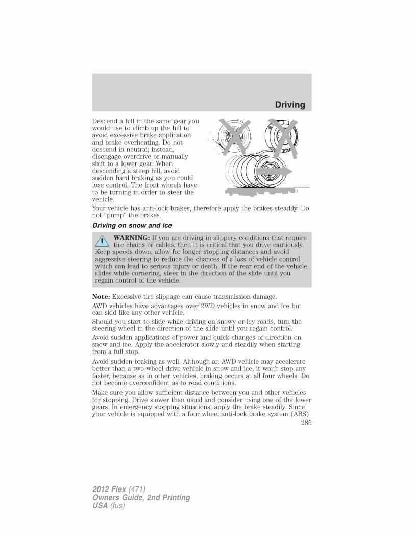
Descend a hill in the same gear youwould use to climb up the hill toavoid excessive brake applicationand brake overheating. Do notdescend in neutral; instead,disengage overdrive or manuallyshift to a lower gear. Whendescending a steep hill, avoidsudden hard braking as you couldlose control. The front wheels haveto be turning in order to steer thevehicle.Your vehicle has anti-lock brakes, therefore apply the brakes steadily. Donot “pump” the brakes.
Driving on snow and ice
WARNING: If you are driving in slippery conditions that requiretire chains or cables, then it is critical that you drive cautiously.
Keep speeds down, allow for longer stopping distances and avoidaggressive steering to reduce the chances of a loss of vehicle controlwhich can lead to serious injury or death. If the rear end of the vehicleslides while cornering, steer in the direction of the slide until youregain control of the vehicle.
Note: Excessive tire slippage can cause transmission damage.AWD vehicles have advantages over 2WD vehicles in snow and ice butcan skid like any other vehicle.Should you start to slide while driving on snowy or icy roads, turn thesteering wheel in the direction of the slide until you regain control.Avoid sudden applications of power and quick changes of direction onsnow and ice. Apply the accelerator slowly and steadily when startingfrom a full stop.
Avoid sudden braking as well. Although an AWD vehicle may acceleratebetter than a two-wheel drive vehicle in snow and ice, it won’t stop anyfaster, because as in other vehicles, braking occurs at all four wheels. Donot become overconfident as to road conditions.
Make sure you allow sufficient distance between you and other vehiclesfor stopping. Drive slower than usual and consider using one of the lowergears. In emergency stopping situations, apply the brake steadily. Sinceyour vehicle is equipped with a four wheel anti-lock brake system (ABS),
Driving
285
2012 Flex (471)Owners Guide, 2nd PrintingUSA (fus)
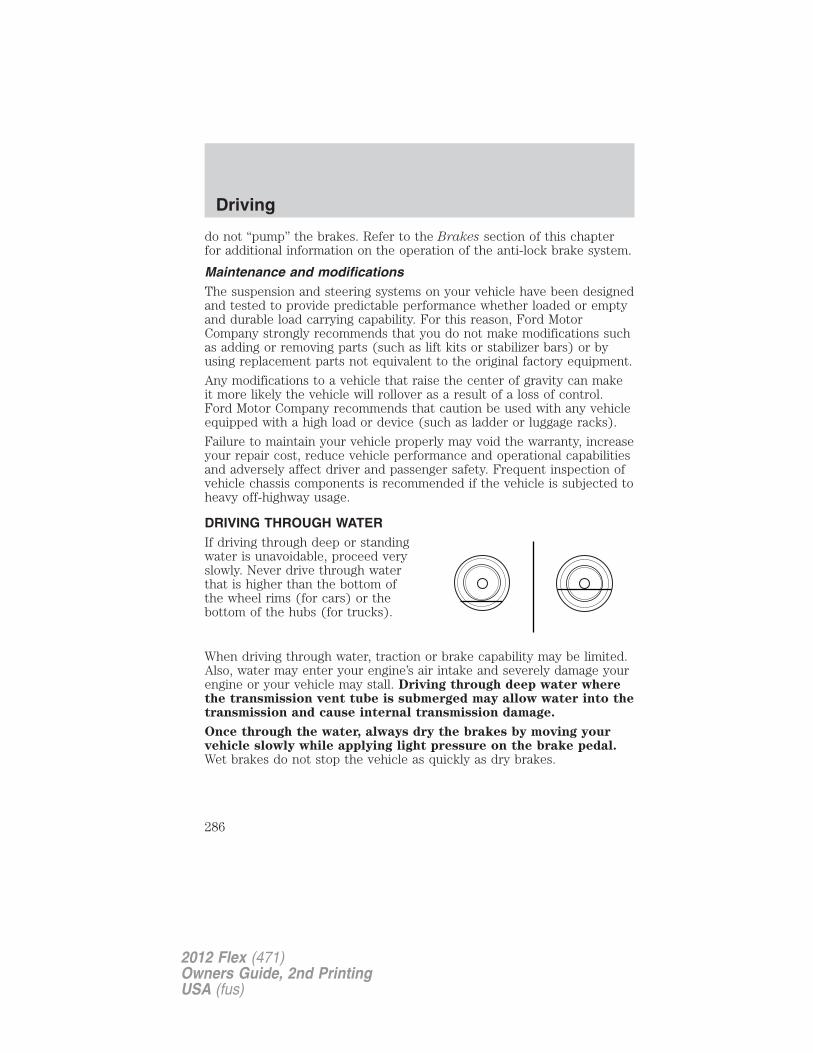
do not “pump” the brakes. Refer to the Brakes section of this chapterfor additional information on the operation of the anti-lock brake system.
Maintenance and modificationsThe suspension and steering systems on your vehicle have been designedand tested to provide predictable performance whether loaded or emptyand durable load carrying capability. For this reason, Ford MotorCompany strongly recommends that you do not make modifications suchas adding or removing parts (such as lift kits or stabilizer bars) or byusing replacement parts not equivalent to the original factory equipment.
Any modifications to a vehicle that raise the center of gravity can makeit more likely the vehicle will rollover as a result of a loss of control.Ford Motor Company recommends that caution be used with any vehicleequipped with a high load or device (such as ladder or luggage racks).
Failure to maintain your vehicle properly may void the warranty, increaseyour repair cost, reduce vehicle performance and operational capabilitiesand adversely affect driver and passenger safety. Frequent inspection ofvehicle chassis components is recommended if the vehicle is subjected toheavy off-highway usage.
DRIVING THROUGH WATERIf driving through deep or standingwater is unavoidable, proceed veryslowly. Never drive through waterthat is higher than the bottom ofthe wheel rims (for cars) or thebottom of the hubs (for trucks).
When driving through water, traction or brake capability may be limited.Also, water may enter your engine’s air intake and severely damage yourengine or your vehicle may stall. Driving through deep water wherethe transmission vent tube is submerged may allow water into thetransmission and cause internal transmission damage.
Once through the water, always dry the brakes by moving yourvehicle slowly while applying light pressure on the brake pedal.Wet brakes do not stop the vehicle as quickly as dry brakes.
Driving
286
2012 Flex (471)Owners Guide, 2nd PrintingUSA (fus)
ROADSIDE ASSISTANCE
Vehicles sold in the U.S. : Getting roadside assistanceTo fully assist you should you have a vehicle concern, Ford MotorCompany offers a complimentary roadside assistance program. Thisprogram is separate from the New Vehicle Limited Warranty. The serviceis available:
• 24-hours, seven days a week
• for the coverage period listed on the Roadside Assistance Cardincluded in your Owner Guide portfolio.
Roadside assistance will cover:
• a flat tire change with a good spare (except vehicles that have beensupplied with a tire inflation kit)
• battery jump start
• lock-out assistance (key replacement cost is the customer’sresponsibility)
• fuel delivery – Independent Service Contractors, if not prohibited bystate, local or municipal law shall deliver up to 2.0 gallons (7.5L) ofgasoline or 5.0 gallons (18.9L) of diesel fuel to a disabled vehicle. Fueldelivery service is limited to two no-charge occurrences within a12-month period.
• winch out – available within 100 feet (30.5 meters) of a paved orcounty maintained road, no recoveries.
• towing – Ford and Lincoln eligible vehicles towed to an authorizeddealer within 35 miles (56 km) of the disablement location or to thenearest authorized dealer. If a member requests to be towed to anauthorized dealer more than 35 miles (56 km) from the disablementlocation, the member shall be responsible for any mileage costs inexcess of 35 miles (56 km).
Trailers shall be covered up to $200 if the disabled eligible vehiclerequires service at the nearest authorized dealer. If the trailer is disabled,but the towing vehicle is operational, the trailer does not qualify for anyroadside services.
Vehicles sold in the U.S. : Using roadside assistanceComplete the roadside assistance identification card and place it in yourwallet for quick reference. This card is found in the Owner’s Guideportfolio in the glove compartment.
Roadside Emergencies
287
2012 Flex (471)Owners Guide, 2nd PrintingUSA (fus)
U.S. Ford vehicle customers who require Roadside Assistance, call1-800-241-3673.If you need to arrange roadside assistance for yourself, Ford MotorCompany will reimburse a reasonable amount for towing to the nearestdealership within 35 miles (56 km). To obtain reimbursementinformation, U.S. Ford vehicle customers call 1-800-241-3673. Customerswill be asked to submit their original receipts.
Vehicles sold in Canada : Getting roadside assistanceCanadian customers who require roadside assistance, call1–800–665–2006.
Vehicles sold in Canada : Using roadside assistanceComplete the roadside assistance identification card and place it in yourwallet for quick reference. In Canada, the card is found in the WarrantyGuide in the glove box.Canadian Roadside coverage and benefits may differ from the U.S.coverage. Please refer to your Warranty Guide or visit our website atwww.ford.ca for information on Canadian services and benefits.Canadian customers who need to obtain roadside information, call1-800-665-2006 or visit our website at www.ford.ca.
HAZARD FLASHER CONTROLThe hazard flasher control is locatedon the instrument panel by theradio. The hazard flashers willoperate when the ignition is in anyposition or if the key is not in theignition.
• Press the flasher control and all front and rear direction signals willflash.
• Press the flasher control again to turn them off.
Use it when your vehicle is disabled and is creating a safety hazard forother motorists.
Note: With extended use, the flasher may run down your battery.
FUEL PUMP SHUT-OFFIn the event of a moderate to severe collision, this vehicle is equippedwith a fuel pump shut-off feature that stops the flow of fuel to theengine. Not every impact will cause a shut-off.
Roadside Emergencies
288
2012 Flex (471)Owners Guide, 2nd PrintingUSA (fus)
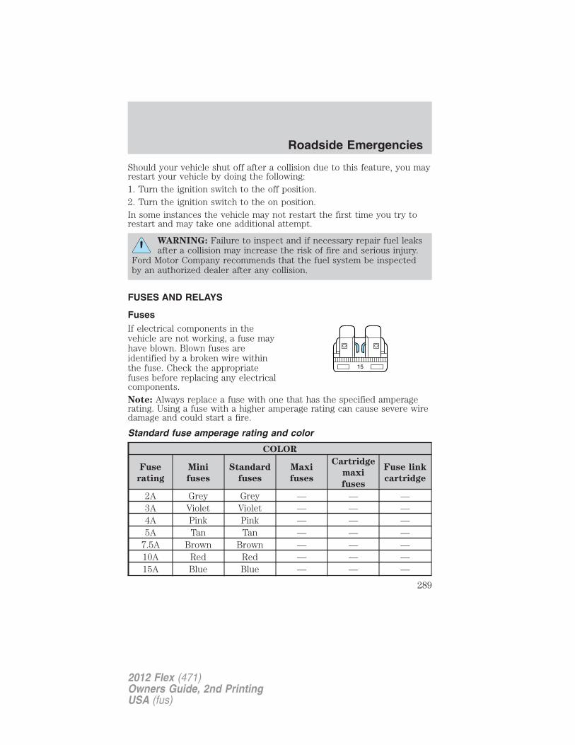
Should your vehicle shut off after a collision due to this feature, you mayrestart your vehicle by doing the following:1. Turn the ignition switch to the off position.2. Turn the ignition switch to the on position.In some instances the vehicle may not restart the first time you try torestart and may take one additional attempt.
WARNING: Failure to inspect and if necessary repair fuel leaksafter a collision may increase the risk of fire and serious injury.
Ford Motor Company recommends that the fuel system be inspectedby an authorized dealer after any collision.
FUSES AND RELAYS
FusesIf electrical components in thevehicle are not working, a fuse mayhave blown. Blown fuses areidentified by a broken wire withinthe fuse. Check the appropriatefuses before replacing any electricalcomponents.Note: Always replace a fuse with one that has the specified amperagerating. Using a fuse with a higher amperage rating can cause severe wiredamage and could start a fire.
Standard fuse amperage rating and color
COLOR
Fuse
rating
Mini
fuses
Standard
fuses
Maxi
fuses
Cartridge
maxi
fuses
Fuse link
cartridge
2A Grey Grey — — —3A Violet Violet — — —4A Pink Pink — — —5A Tan Tan — — —
7.5A Brown Brown — — —10A Red Red — — —15A Blue Blue — — —
15
Roadside Emergencies
289
2012 Flex (471)Owners Guide, 2nd PrintingUSA (fus)
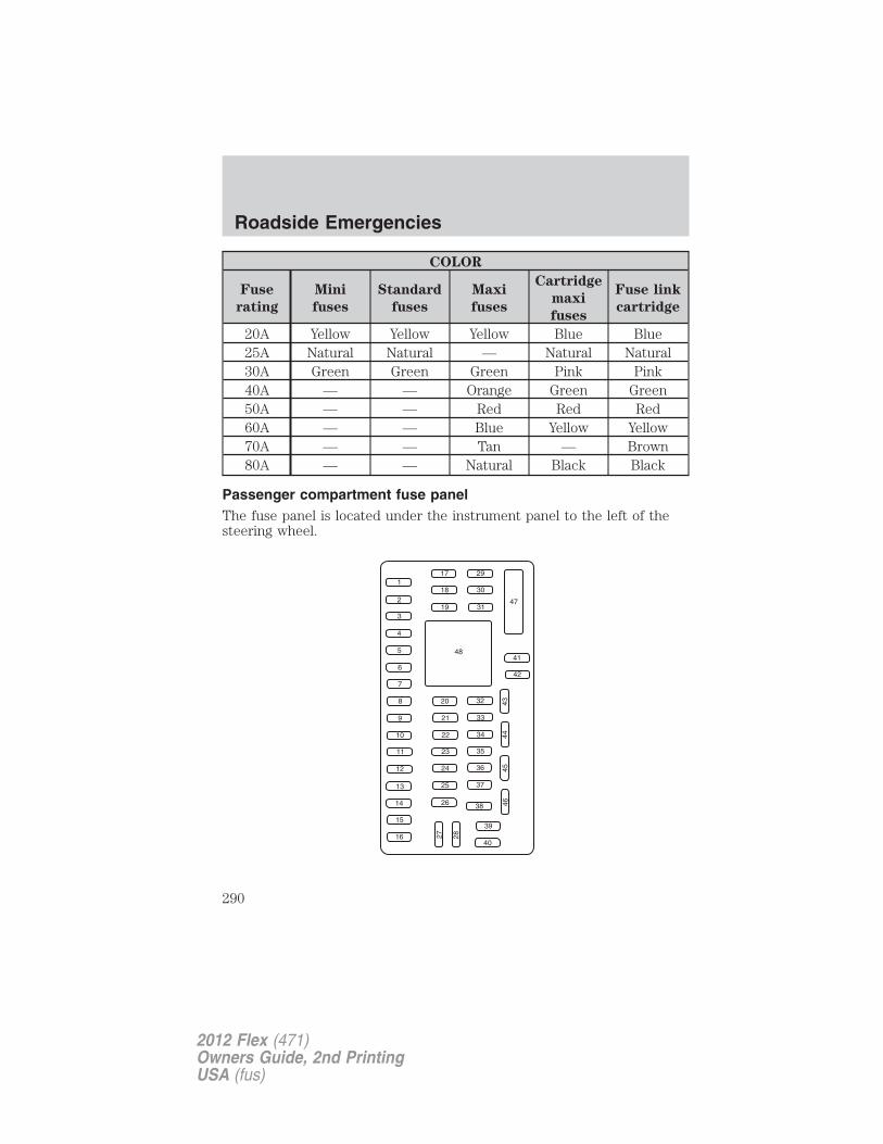
COLOR
Fuse
rating
Mini
fuses
Standard
fuses
Maxi
fuses
Cartridge
maxi
fuses
Fuse link
cartridge
20A Yellow Yellow Yellow Blue Blue25A Natural Natural — Natural Natural30A Green Green Green Pink Pink40A — — Orange Green Green50A — — Red Red Red60A — — Blue Yellow Yellow70A — — Tan — Brown80A — — Natural Black Black
Passenger compartment fuse panelThe fuse panel is located under the instrument panel to the left of thesteering wheel.
Roadside Emergencies
290
2012 Flex (471)Owners Guide, 2nd PrintingUSA (fus)
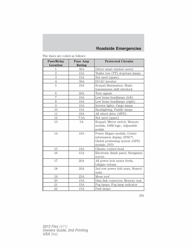
The fuses are coded as follows:
Fuse/Relay
Location
Fuse Amp
Rating
Protected Circuits
1 30A Driver smart window motor2 15A Trailer tow (TT) stop/turn lamps3 15A Not used (spare)4 30A DC/AC inverter5 10A Keypad illumination, Brake
transmission shift interlock6 20A Turn signals7 10A Low beam headlamps (left)8 10A Low beam headlamps (right)9 15A Interior lights, Cargo lamps
10 15A Backlighting, Puddle lamps11 10A All wheel drive (AWD)12 7.5A Not used (spare)13 5A Keypad, Mirror switch, Memory
module, DSM logic, Adjustablepedals
14 10A Power liftgate module, Centerinformation display, SYNC�,Global positioning system (GPS)module, DVD
15 10A Climate control head16 15A Electronic finish panel, Navigation
screen17 20A All power lock motor feeds,
Liftgate release18 20A 2nd row power fold seats, Heated
seats19 25A Moon roof20 15A Data link connector, Memory seat21 15A Fog lamps, Fog lamp indicator22 15A Park lamps
Roadside Emergencies
291
2012 Flex (471)Owners Guide, 2nd PrintingUSA (fus)
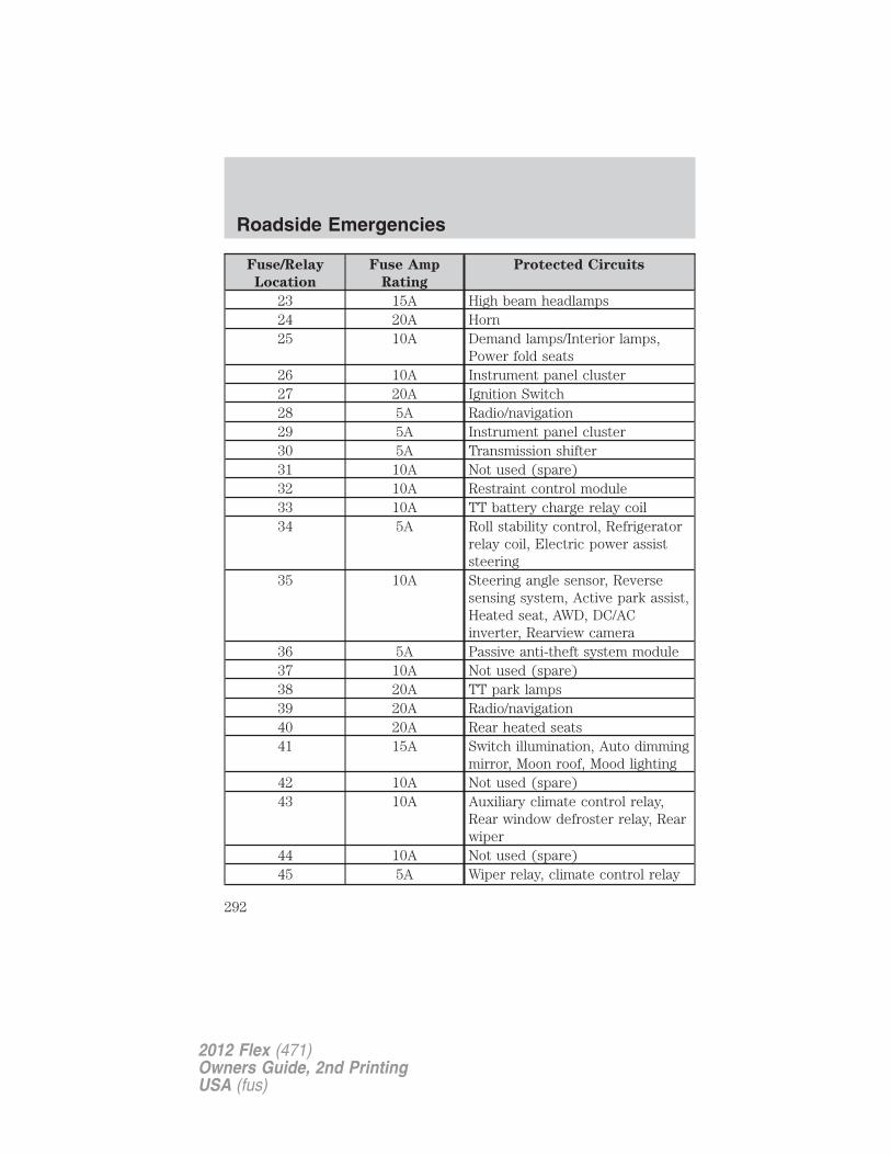
Fuse/Relay
Location
Fuse Amp
Rating
Protected Circuits
23 15A High beam headlamps24 20A Horn25 10A Demand lamps/Interior lamps,
Power fold seats26 10A Instrument panel cluster27 20A Ignition Switch28 5A Radio/navigation29 5A Instrument panel cluster30 5A Transmission shifter31 10A Not used (spare)32 10A Restraint control module33 10A TT battery charge relay coil34 5A Roll stability control, Refrigerator
relay coil, Electric power assiststeering
35 10A Steering angle sensor, Reversesensing system, Active park assist,Heated seat, AWD, DC/ACinverter, Rearview camera
36 5A Passive anti-theft system module37 10A Not used (spare)38 20A TT park lamps39 20A Radio/navigation40 20A Rear heated seats41 15A Switch illumination, Auto dimming
mirror, Moon roof, Mood lighting42 10A Not used (spare)43 10A Auxiliary climate control relay,
Rear window defroster relay, Rearwiper
44 10A Not used (spare)45 5A Wiper relay, climate control relay
Roadside Emergencies
292
2012 Flex (471)Owners Guide, 2nd PrintingUSA (fus)
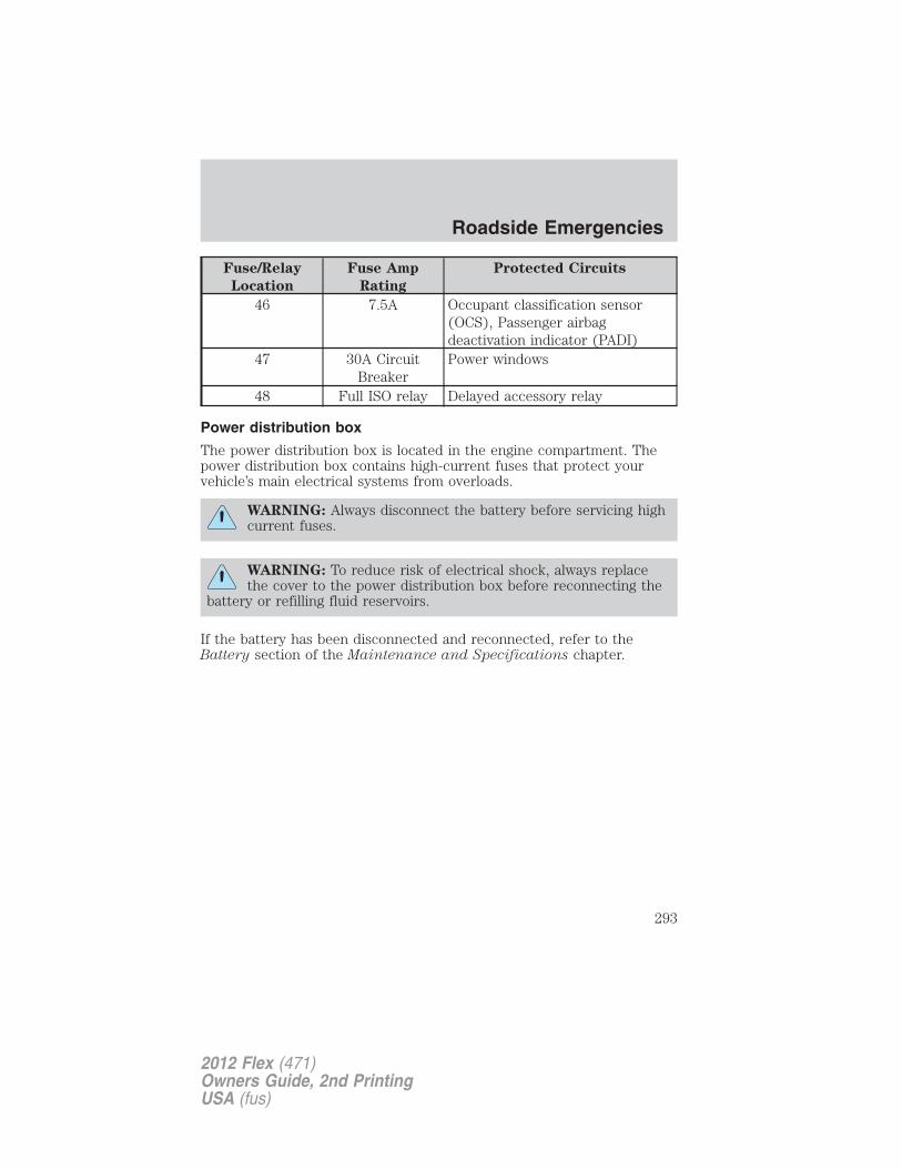
Fuse/Relay
Location
Fuse Amp
Rating
Protected Circuits
46 7.5A Occupant classification sensor(OCS), Passenger airbagdeactivation indicator (PADI)
47 30A CircuitBreaker
Power windows
48 Full ISO relay Delayed accessory relay
Power distribution box
The power distribution box is located in the engine compartment. Thepower distribution box contains high-current fuses that protect yourvehicle’s main electrical systems from overloads.
WARNING: Always disconnect the battery before servicing highcurrent fuses.
WARNING: To reduce risk of electrical shock, always replacethe cover to the power distribution box before reconnecting the
battery or refilling fluid reservoirs.
If the battery has been disconnected and reconnected, refer to theBattery section of the Maintenance and Specifications chapter.
Roadside Emergencies
293
2012 Flex (471)Owners Guide, 2nd PrintingUSA (fus)
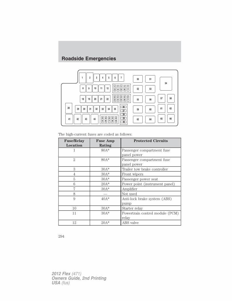
The high-current fuses are coded as follows:
Fuse/Relay
Location
Fuse Amp
Rating
Protected Circuits
1 80A* Passenger compartment fusepanel power
2 80A* Passenger compartment fusepanel power
3 30A* Trailer tow brake controller4 30A* Front wipers5 30A* Passenger power seat6 20A* Power point (instrument panel)7 30A* Amplifier8 — Not used9 40A* Anti-lock brake system (ABS)
pump10 30A* Starter relay11 30A* Powertrain control module (PCM)
relay12 20A* ABS valve
Roadside Emergencies
294
2012 Flex (471)Owners Guide, 2nd PrintingUSA (fus)
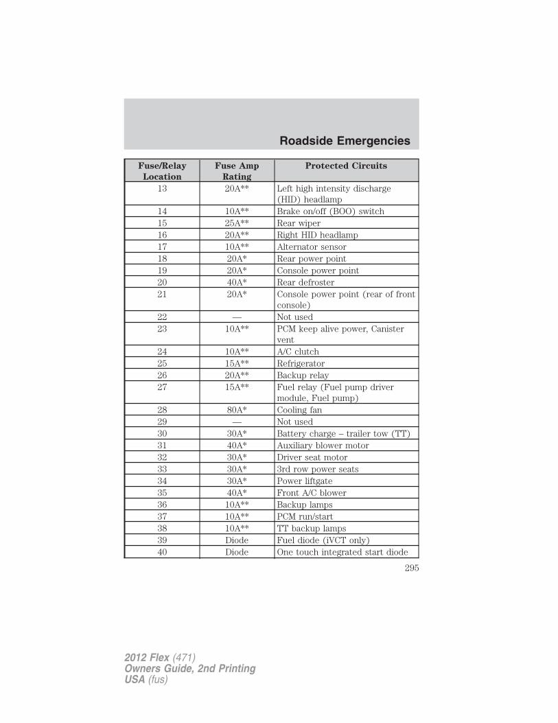
Fuse/Relay
Location
Fuse Amp
Rating
Protected Circuits
13 20A** Left high intensity discharge(HID) headlamp
14 10A** Brake on/off (BOO) switch15 25A** Rear wiper16 20A** Right HID headlamp17 10A** Alternator sensor18 20A* Rear power point19 20A* Console power point20 40A* Rear defroster21 20A* Console power point (rear of front
console)22 — Not used23 10A** PCM keep alive power, Canister
vent24 10A** A/C clutch25 15A** Refrigerator26 20A** Backup relay27 15A** Fuel relay (Fuel pump driver
module, Fuel pump)28 80A* Cooling fan29 — Not used30 30A* Battery charge – trailer tow (TT)31 40A* Auxiliary blower motor32 30A* Driver seat motor33 30A* 3rd row power seats34 30A* Power liftgate35 40A* Front A/C blower36 10A** Backup lamps37 10A** PCM run/start38 10A** TT backup lamps39 Diode Fuel diode (iVCT only)40 Diode One touch integrated start diode
Roadside Emergencies
295
2012 Flex (471)Owners Guide, 2nd PrintingUSA (fus)
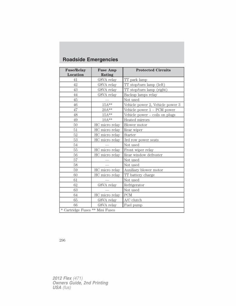
Fuse/Relay
Location
Fuse Amp
Rating
Protected Circuits
41 G8VA relay TT park lamp42 G8VA relay TT stop/turn lamp (left)43 G8VA relay TT stop/turn lamp (right)44 G8VA relay Backup lamps relay45 — Not used46 15A** Vehicle power 2, Vehicle power 347 20A** Vehicle power 1 – PCM power48 15A** Vehicle power – coils on plugs49 10A** Heated mirrors50 HC micro relay Blower motor51 HC micro relay Rear wiper52 HC micro relay Starter53 HC micro relay 3rd row power seats54 — Not used55 HC micro relay Front wiper relay56 HC micro relay Rear window defroster57 — Not used58 — Not used59 HC micro relay Auxiliary blower motor60 HC micro relay TT battery charge61 — Not used62 G8VA relay Refrigerator63 — Not used64 HC micro relay PCM65 G8VA relay A/C clutch66 G8VA relay Fuel pump
* Cartridge Fuses ** Mini Fuses
Roadside Emergencies
296
2012 Flex (471)Owners Guide, 2nd PrintingUSA (fus)
CHANGING THE TIRESIf you get a flat tire while driving, do not apply the brake heavily.Instead, gradually decrease your speed. Hold the steering wheel firmlyand slowly move to a safe place on the side of the road.
Note: The tire pressure monitoring system (TPMS) indicator light willilluminate when the spare tire is in use. To restore the full functionalityof the monitoring system, all road wheels equipped with tire pressuremonitoring sensors must be mounted on the vehicle.
Have a flat serviced by an authorized dealer in order to prevent damageto the TPMS sensors, refer to Tire pressure monitoring system(TPMS) in the Tires, Wheels and Loading chapter. Replace the sparetire with a road tire as soon as possible. During repairing or replacing ofthe flat tire, have the authorized dealer inspect the TPMS sensor fordamage.
WARNING: The use of tire sealants may damage your tirepressure monitoring system (TPMS) and should not be used.
However, if you must use a sealant, the TPMS sensor and valve stemon the wheel must be replaced by an authorized Ford dealer.
WARNING: Refer to Tire pressure monitoring system (TPMS)in the Tires, Wheels and Loading chapter for important
information. If the tire pressure monitor sensor becomes damaged, itwill no longer function.
Dissimilar spare tire/wheel information
WARNING: Failure to follow these guidelines could result in anincreased risk of loss of vehicle control, injury or death.
If you have a dissimilar spare tire/wheel, then it is intended fortemporary use only. This means that if you need to use it, you shouldreplace it as soon as possible with a road tire/wheel that is the same sizeand type as the road tires and wheels that were originally provided byFord. If the dissimilar spare tire or wheel is damaged, it should bereplaced rather than repaired.
Roadside Emergencies
297
2012 Flex (471)Owners Guide, 2nd PrintingUSA (fus)
A dissimilar spare tire/wheel is defined as a spare tire and/or wheel thatis different in brand, size or appearance from the road tires and wheelsand can be one of three types:
1. T-type mini-spare: This spare tire begins with the letter “T” for tiresize and may have “Temporary Use Only” molded in the sidewall
2. Full-size dissimilar spare with label on wheel: This spare tire hasa label on the wheel that states: “THIS TIRE AND WHEEL FORTEMPORARY USE ONLY”
When driving with one of the dissimilar spare tires listed above, do not:
• Exceed 50 mph (80 km/h)
• Load the vehicle beyond maximum vehicle load rating listed on theSafety Compliance Label
• Tow a trailer
• Use snow chains on the end of the vehicle with the dissimilar sparetire
• Use more than one dissimilar spare tire at a time
• Use commercial car washing equipment
• Try to repair the dissimilar spare tire
Use of one of the dissimilar spare tires listed above at any one wheellocation can lead to impairment of the following:
• Handling, stability and braking performance
• Comfort and noise
• Ground clearance and parking at curbs
• Winter weather driving capability
• Wet weather driving capability
3. Full-size dissimilar spare without label on wheel
When driving with the full-size dissimilar spare tire/wheel, do not:
• Exceed 70 mph (113 km/h)
• Use more than one dissimilar spare tire/wheel at a time
• Use commercial car washing equipment
• Use snow chains on the end of the vehicle with the dissimilar sparetire/wheel
Roadside Emergencies
298
2012 Flex (471)Owners Guide, 2nd PrintingUSA (fus)
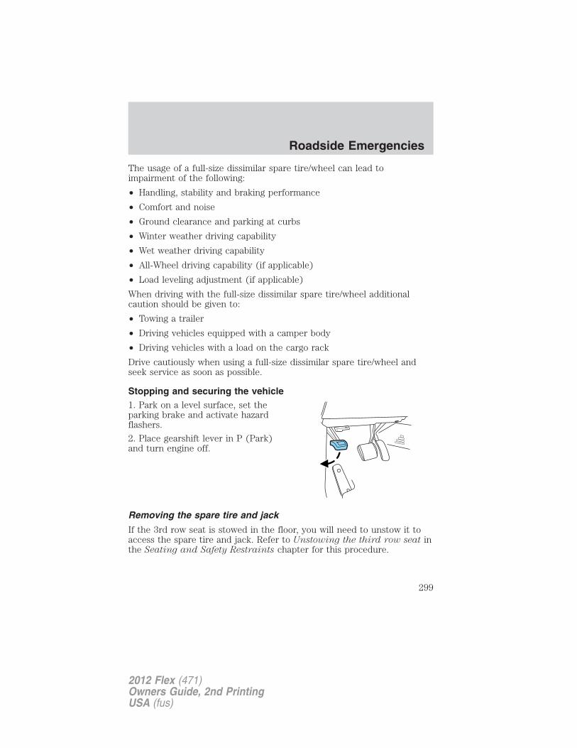
The usage of a full-size dissimilar spare tire/wheel can lead toimpairment of the following:
• Handling, stability and braking performance
• Comfort and noise
• Ground clearance and parking at curbs
• Winter weather driving capability
• Wet weather driving capability
• All-Wheel driving capability (if applicable)
• Load leveling adjustment (if applicable)
When driving with the full-size dissimilar spare tire/wheel additionalcaution should be given to:
• Towing a trailer
• Driving vehicles equipped with a camper body
• Driving vehicles with a load on the cargo rack
Drive cautiously when using a full-size dissimilar spare tire/wheel andseek service as soon as possible.
Stopping and securing the vehicle1. Park on a level surface, set theparking brake and activate hazardflashers.
2. Place gearshift lever in P (Park)and turn engine off.
Removing the spare tire and jack
If the 3rd row seat is stowed in the floor, you will need to unstow it toaccess the spare tire and jack. Refer to Unstowing the third row seat inthe Seating and Safety Restraints chapter for this procedure.
Roadside Emergencies
299
2012 Flex (471)Owners Guide, 2nd PrintingUSA (fus)
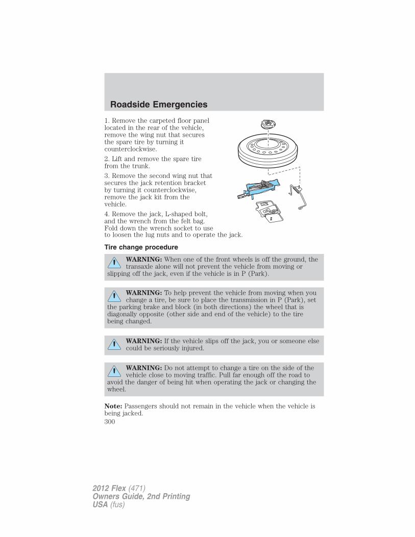
1. Remove the carpeted floor panellocated in the rear of the vehicle,remove the wing nut that securesthe spare tire by turning itcounterclockwise.
2. Lift and remove the spare tirefrom the trunk.
3. Remove the second wing nut thatsecures the jack retention bracketby turning it counterclockwise,remove the jack kit from thevehicle.
4. Remove the jack, L-shaped bolt,and the wrench from the felt bag.Fold down the wrench socket to useto loosen the lug nuts and to operate the jack.
Tire change procedure
WARNING: When one of the front wheels is off the ground, thetransaxle alone will not prevent the vehicle from moving or
slipping off the jack, even if the vehicle is in P (Park).
WARNING: To help prevent the vehicle from moving when youchange a tire, be sure to place the transmission in P (Park), set
the parking brake and block (in both directions) the wheel that isdiagonally opposite (other side and end of the vehicle) to the tirebeing changed.
WARNING: If the vehicle slips off the jack, you or someone elsecould be seriously injured.
WARNING: Do not attempt to change a tire on the side of thevehicle close to moving traffic. Pull far enough off the road to
avoid the danger of being hit when operating the jack or changing thewheel.
Note: Passengers should not remain in the vehicle when the vehicle isbeing jacked.
Roadside Emergencies
300
2012 Flex (471)Owners Guide, 2nd PrintingUSA (fus)
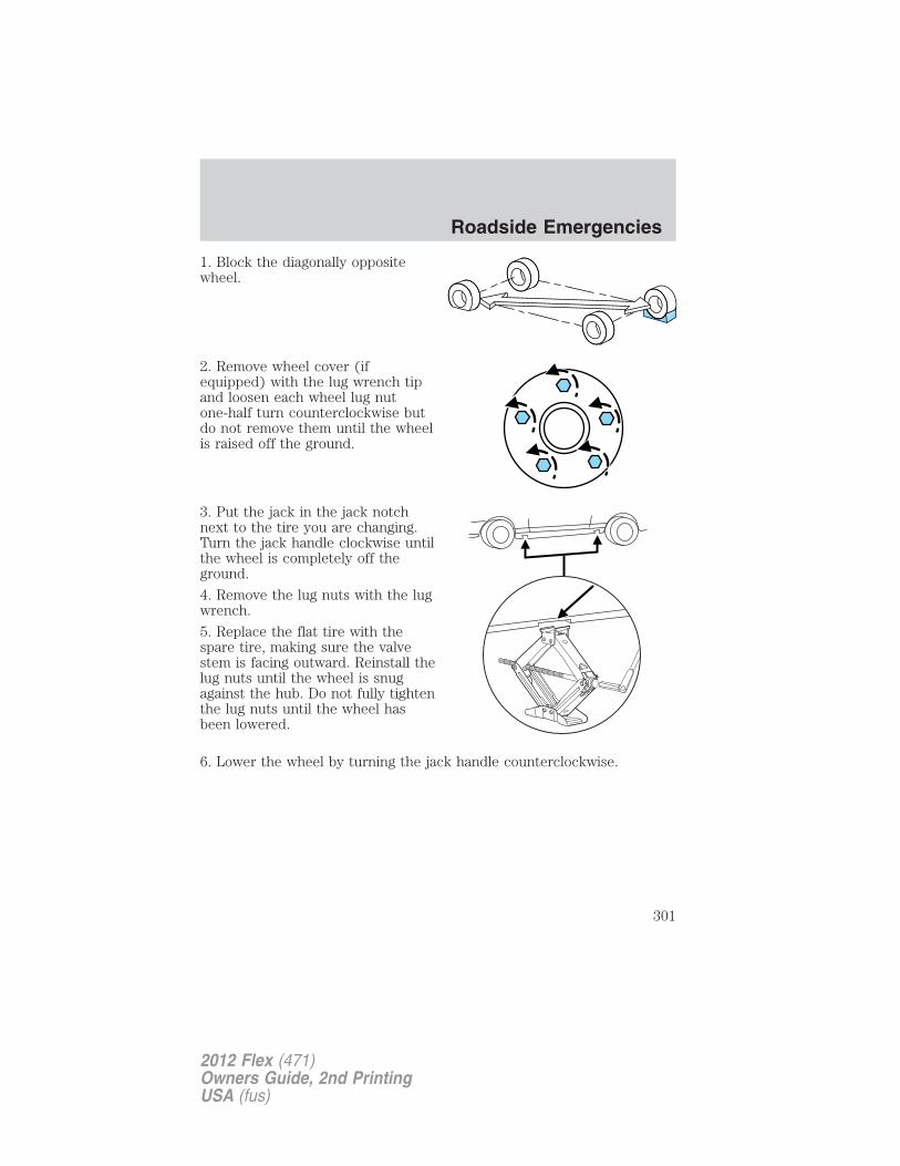
1. Block the diagonally oppositewheel.
2. Remove wheel cover (ifequipped) with the lug wrench tipand loosen each wheel lug nutone-half turn counterclockwise butdo not remove them until the wheelis raised off the ground.
3. Put the jack in the jack notchnext to the tire you are changing.Turn the jack handle clockwise untilthe wheel is completely off theground.
4. Remove the lug nuts with the lugwrench.
5. Replace the flat tire with thespare tire, making sure the valvestem is facing outward. Reinstall thelug nuts until the wheel is snugagainst the hub. Do not fully tightenthe lug nuts until the wheel hasbeen lowered.
6. Lower the wheel by turning the jack handle counterclockwise.
Roadside Emergencies
301
2012 Flex (471)Owners Guide, 2nd PrintingUSA (fus)
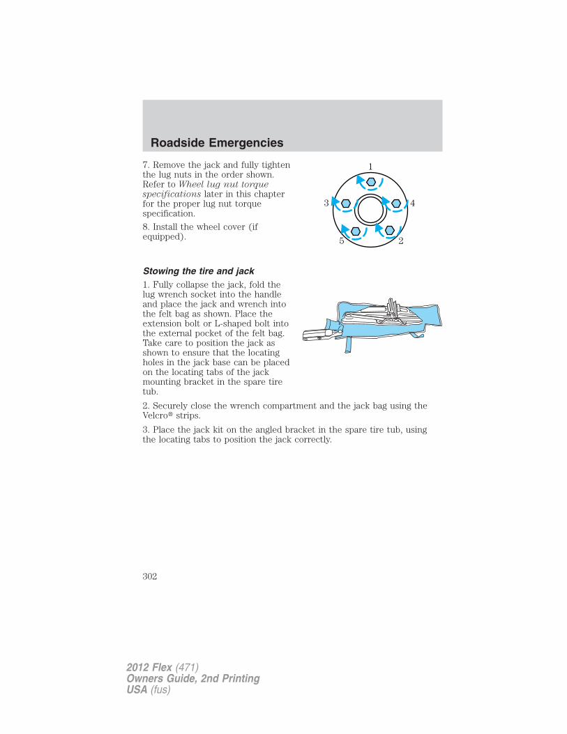
7. Remove the jack and fully tightenthe lug nuts in the order shown.Refer to Wheel lug nut torquespecifications later in this chapterfor the proper lug nut torquespecification.
8. Install the wheel cover (ifequipped).
Stowing the tire and jack1. Fully collapse the jack, fold thelug wrench socket into the handleand place the jack and wrench intothe felt bag as shown. Place theextension bolt or L-shaped bolt intothe external pocket of the felt bag.Take care to position the jack asshown to ensure that the locatingholes in the jack base can be placedon the locating tabs of the jackmounting bracket in the spare tiretub.
2. Securely close the wrench compartment and the jack bag using theVelcro� strips.
3. Place the jack kit on the angled bracket in the spare tire tub, usingthe locating tabs to position the jack correctly.
1
43
25
Roadside Emergencies
302
2012 Flex (471)Owners Guide, 2nd PrintingUSA (fus)
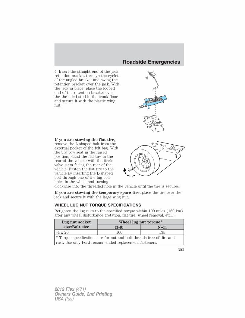
4. Insert the straight end of the jackretention bracket through the eyeletof the angled bracket and swing theretention bracket over the jack. Withthe jack in place, place the loopedend of the retention bracket overthe threaded stud in the trunk floorand secure it with the plastic wingnut.
If you are stowing the flat tire,remove the L-shaped bolt from theexternal pocket of the felt bag. Withthe 3rd row seat in the raisedposition, stand the flat tire in therear of the vehicle with the tire’svalve stem facing the rear of thevehicle. Fasten the flat tire to thevehicle by inserting the L-shapedbolt through one of the lug boltholes in the wheel and turningclockwise into the threaded hole in the vehicle until the tire is secured.
If you are stowing the temporary spare tire, place the tire over thejack and secure it with the large wing nut.
WHEEL LUG NUT TORQUE SPECIFICATIONSRetighten the lug nuts to the specified torque within 100 miles (160 km)after any wheel disturbance (rotation, flat tire, wheel removal, etc.).
Lug nut socket
size/Bolt size
Wheel lug nut torque*
ft-lb N•m1⁄2 x 20 100 135* Torque specifications are for nut and bolt threads free of dirt andrust. Use only Ford recommended replacement fasteners.
Roadside Emergencies
303
2012 Flex (471)Owners Guide, 2nd PrintingUSA (fus)
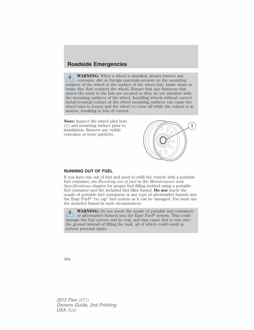
WARNING: When a wheel is installed, always remove anycorrosion, dirt or foreign materials present on the mounting
surfaces of the wheel or the surface of the wheel hub, brake drum orbrake disc that contacts the wheel. Ensure that any fasteners thatattach the rotor to the hub are secured so they do not interfere withthe mounting surfaces of the wheel. Installing wheels without correctmetal-to-metal contact at the wheel mounting surfaces can cause thewheel nuts to loosen and the wheel to come off while the vehicle is inmotion, resulting in loss of control.
Note: Inspect the wheel pilot hole(1) and mounting surface prior toinstallation. Remove any visiblecorrosion or loose particles.
RUNNING OUT OF FUELIf you have run out of fuel and need to refill the vehicle with a portablefuel container, see Running out of fuel in the Maintenance andSpecifications chapter for proper fuel filling method using a portablefuel container and the included fuel filler funnel. Do not insert thenozzle of portable fuel containers or any type of aftermarket funnels intothe Easy Fuel� “no cap” fuel system as it can be damaged. You must usethe included funnel in such circumstances.
WARNING: Do not insert the nozzle of portable fuel containersor aftermarket funnels into the Easy Fuel� system. This could
damage the fuel system and its seal, and may cause fuel to run ontothe ground instead of filling the tank, all of which could result inserious personal injury.
Roadside Emergencies
304
2012 Flex (471)Owners Guide, 2nd PrintingUSA (fus)
JUMP STARTING
WARNING: The gases around the battery can explode ifexposed to flames, sparks, or lit cigarettes. An explosion could
result in injury or vehicle damage.
WARNING: Batteries contain sulfuric acid which can burn skin,eyes and clothing, if contacted.
Do not attempt to push-start your automatic transmissionvehicle. Automatic transmissions do not have push-startcapability. Attempting to push-start a vehicle with an automatictransmission may cause transmission damage.
Preparing your vehicleWhen the battery is disconnected or a new battery is installed, theautomatic transmission must relearn its shift strategy. As a result, thetransmission may have firm and/or soft shifts. This operation isconsidered normal and will not affect function or durability of thetransmission. Over time, the adaptive learning process will fully updatetransmission operation.
1. Use only a 12–volt supply to start your vehicle.
2. Do not disconnect the battery of the disabled vehicle as this coulddamage the vehicle’s electrical system.
3. Park the booster vehicle close to the hood of the disabled vehiclemaking sure the two vehicles do not touch. Set the parking brake onboth vehicles and stay clear of the engine cooling fan and other movingparts.
4. Check all battery terminals and remove any excessive corrosion beforeyou attach the battery cables. Ensure that vent caps are tight and level.
5. Turn the heater fan on in both vehicles to protect from any electricalsurges. Turn all other accessories off.
Roadside Emergencies
305
2012 Flex (471)Owners Guide, 2nd PrintingUSA (fus)
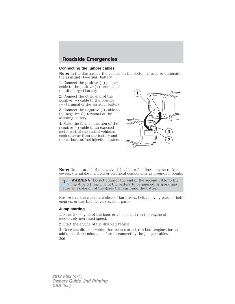
Connecting the jumper cablesNote: In the illustration, the vehicle on the bottom is used to designatethe assisting (boosting) battery.
1. Connect the positive (+) jumpercable to the positive (+) terminal ofthe discharged battery.
2. Connect the other end of thepositive (+) cable to the positive(+) terminal of the assisting battery.
3. Connect the negative (-) cable tothe negative (-) terminal of theassisting battery.
4. Make the final connection of thenegative (-) cable to an exposedmetal part of the stalled vehicle’sengine, away from the battery andthe carburetor/fuel injection system.
Note: Do not attach the negative (-) cable to fuel lines, engine rockercovers, the intake manifold or electrical components as grounding points.
WARNING: Do not connect the end of the second cable to thenegative (-) terminal of the battery to be jumped. A spark may
cause an explosion of the gases that surround the battery.
Ensure that the cables are clear of fan blades, belts, moving parts of bothengines, or any fuel delivery system parts.
Jump starting1. Start the engine of the booster vehicle and run the engine atmoderately increased speed.
2. Start the engine of the disabled vehicle.
3. Once the disabled vehicle has been started, run both engines for anadditional three minutes before disconnecting the jumper cables.
+
–
+
–
2
3
14
Roadside Emergencies
306
2012 Flex (471)Owners Guide, 2nd PrintingUSA (fus)
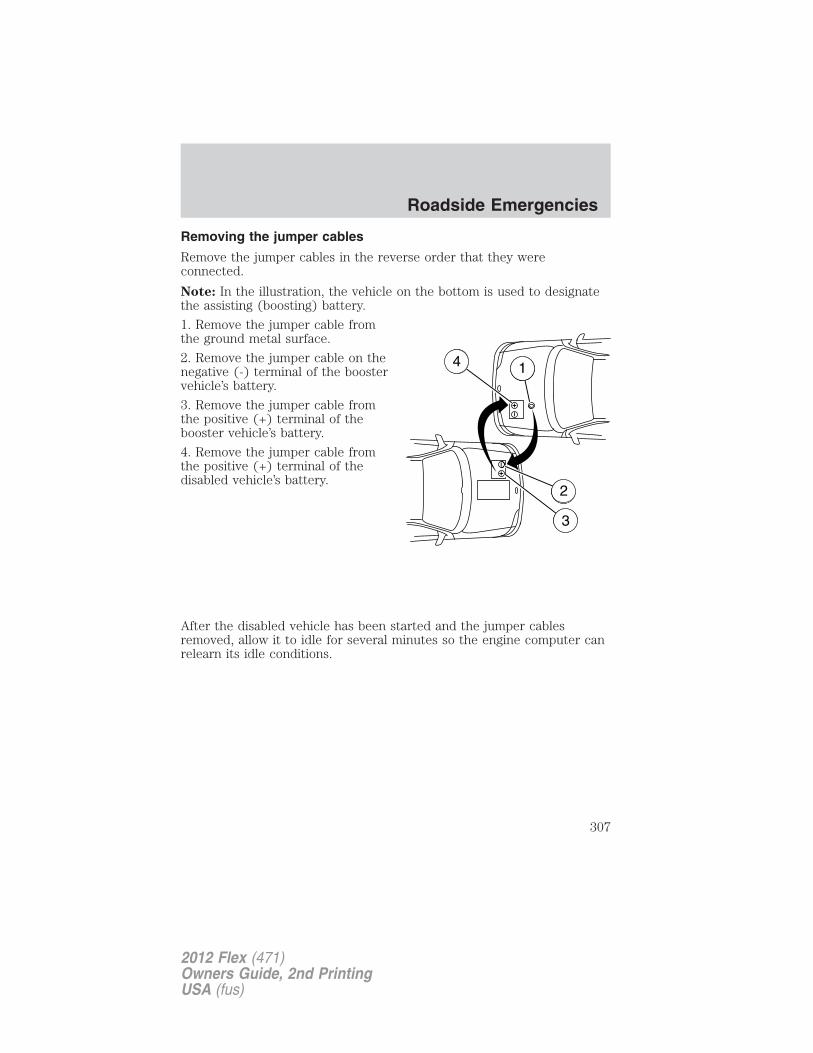
Removing the jumper cables
Remove the jumper cables in the reverse order that they wereconnected.
Note: In the illustration, the vehicle on the bottom is used to designatethe assisting (boosting) battery.
1. Remove the jumper cable fromthe ground metal surface.
2. Remove the jumper cable on thenegative (-) terminal of the boostervehicle’s battery.
3. Remove the jumper cable fromthe positive (+) terminal of thebooster vehicle’s battery.
4. Remove the jumper cable fromthe positive (+) terminal of thedisabled vehicle’s battery.
After the disabled vehicle has been started and the jumper cablesremoved, allow it to idle for several minutes so the engine computer canrelearn its idle conditions.
+
–
+
–
D A
B
C
4 D1
2
3
Roadside Emergencies
307
2012 Flex (471)Owners Guide, 2nd PrintingUSA (fus)
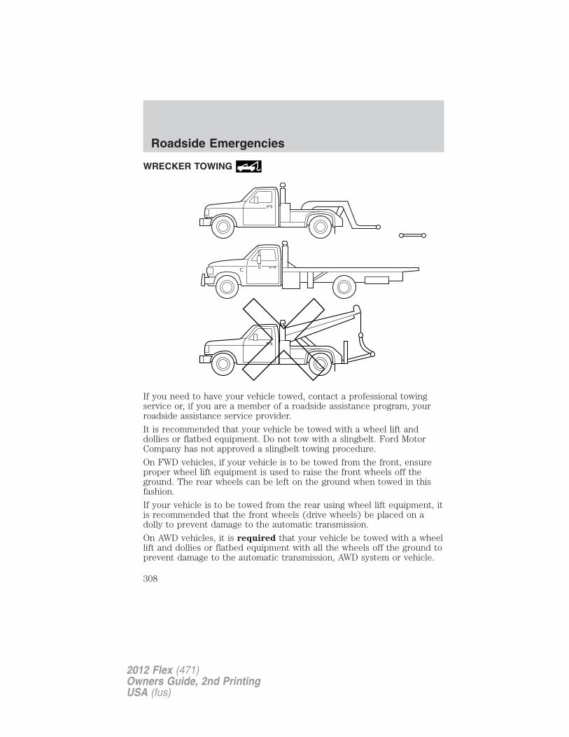
WRECKER TOWING
If you need to have your vehicle towed, contact a professional towingservice or, if you are a member of a roadside assistance program, yourroadside assistance service provider.
It is recommended that your vehicle be towed with a wheel lift anddollies or flatbed equipment. Do not tow with a slingbelt. Ford MotorCompany has not approved a slingbelt towing procedure.
On FWD vehicles, if your vehicle is to be towed from the front, ensureproper wheel lift equipment is used to raise the front wheels off theground. The rear wheels can be left on the ground when towed in thisfashion.
If your vehicle is to be towed from the rear using wheel lift equipment, itis recommended that the front wheels (drive wheels) be placed on adolly to prevent damage to the automatic transmission.
On AWD vehicles, it is required that your vehicle be towed with a wheellift and dollies or flatbed equipment with all the wheels off the ground toprevent damage to the automatic transmission, AWD system or vehicle.
Roadside Emergencies
308
2012 Flex (471)Owners Guide, 2nd PrintingUSA (fus)
If the vehicle is towed by other means or incorrectly, vehicledamage may occur.
Ford Motor Company produces a towing manual for all authorized towtruck operators. Have your tow truck operator refer to this manual forproper hook-up and towing procedures for your vehicle.
Emergency towingIn case of a roadside emergency with a disabled vehicle (without accessto wheel dollies, car hauling trailer, or flatbed transport vehicle) yourvehicle (regardless of transmission powertrain configuration) can be flattowed (all wheels on the ground) under the following conditions:
• Vehicle is facing forward so that it is being towed in a forwarddirection.
• Place the transmission in N (Neutral). Refer to Brake-shift interlockin the Driving chapter for specific instructions if you cannot move thegear shift lever into N (Neutral).
• Maximum speed is not to exceed 35 mph (56 km/h).
• Maximum distance is 50 miles (80 km).
Roadside Emergencies
309
2012 Flex (471)Owners Guide, 2nd PrintingUSA (fus)
GETTING THE SERVICES YOU NEEDWarranty repairs to your vehicle must be performed by an authorizeddealer. While any authorized dealer handling your vehicle line willprovide warranty service, we recommend you return to your sellingauthorized dealer who wants to ensure your continued satisfaction.Please note that certain warranty repairs require special training and/orequipment, so not all authorized dealers are authorized to perform allwarranty repairs. This means that, depending on the warranty repairneeded, you may have to take your vehicle to another authorized dealer.A reasonable time must be allowed to perform a repair after taking yourvehicle to the authorized dealer. Repairs will be made using Ford orMotorcraft� parts, or remanufactured or other parts that are authorizedby Ford.
Away from homeIf you are away from home when your vehicle needs service, contact theFord Customer Relationship Center or use the online resources listedbelow to find the nearest authorized dealer.
In the United States:
Mailing addressFord Motor CompanyCustomer Relationship CenterP.O. Box 6248Dearborn, MI 48121
Telephone1-800-392-3673 (FORD)(TDD for the hearing impaired: 1-800-232-5952)
OnlineAdditional information and resources are available online atfordowner.com
These are some of the items that can be found online:• U.S. dealer locator by Dealer Name, City/State, or Zip Code• Owner Guides• Maintenance Schedules• Recalls• Ford Extended Service Plans• Ford Genuine Accessories• Service specials and promotions.
Customer Assistance
310
2012 Flex (471)Owners Guide, 2nd PrintingUSA (fus)
In Canada:
Mailing address
Customer Relationship CentreFord Motor Company of Canada, LimitedP.O. Box 2000Oakville, Ontario L6J 5E4
Telephone
1-800-565-3673 (FORD)
Online
www.ford.ca
Additional assistance
If you have questions or concerns, or are unsatisfied with the service youare receiving, follow these steps:
1. Contact your Sales Representative or Service Advisor at yourselling/servicing authorized dealer.
2. If your inquiry or concern remains unresolved, contact the SalesManager, Service Manager or Customer Relations Manager.
3. If you require assistance or clarification on Ford Motor Companypolicies, please contact the Ford Customer Relationship Center
In order to help you serve you better, please have the followinginformation available when contacting a Customer Relationship Center:
• Vehicle Identification Number (VIN)
• Your telephone number (home and business)
• The name of the authorized dealer and city where located
• The vehicle’s current odometer reading
In some states, you must directly notify Ford in writing before pursuingremedies under your state’s warranty laws. Ford is also allowed a finalrepair attempt in some states.
In the United States, a warranty dispute must be submitted to the BBBAUTO LINE before taking action under the Magnuson-Moss WarrantyAct, or to the extent allowed by state law, before pursuing replacementor repurchase remedies provided by certain state laws. This disputehandling procedure is not required prior to enforcing state created rightsor other rights which are independent of the Magnuson-Moss WarrantyAct or state replacement or repurchase laws.
Customer Assistance
311
2012 Flex (471)Owners Guide, 2nd PrintingUSA (fus)

IN CALIFORNIA (U.S. ONLY)California Civil Code Section 1793.2(d) requires that, if a manufactureror its representative is unable to repair a motor vehicle to conform to thevehicle’s applicable express warranty after a reasonable number ofattempts, the manufacturer shall be required to either replace thevehicle with one substantially identical or repurchase the vehicle andreimburse the buyer in an amount equal to the actual price paid orpayable by the consumer (less a reasonable allowance for consumeruse). The consumer has the right to choose whether to receive a refundor replacement vehicle.
California Civil Code Section 1793.22(b) presumes that the manufacturerhas had a reasonable number of attempts to conform the vehicle to itsapplicable express warranties if, within the first 18 months of ownershipof a new vehicle or the first 18,000 miles (29,000 km), whichever occursfirst:
1. Two or more repair attempts are made on the same non-conformitylikely to cause death or serious bodily injury OR
2. Four or more repair attempts are made on the same nonconformity (adefect or condition that substantially impairs the use, value or safety ofthe vehicle) OR
3. The vehicle is out of service for repair of nonconformities for a total ofmore than 30 calendar days (not necessarily all at one time)
In the case of 1 or 2 above, the consumer must also notify themanufacturer of the need for the repair of the nonconformity at thefollowing address:
Ford Motor Company16800 Executive Plaza DriveMail Drop 3NE-BDearborn, MI 48126
You are required to submit your warranty dispute to BBB AUTO LINEbefore asserting in court any rights or remedies conferred by CaliforniaCivil Code Section 1793.22(b). You are also required to use BBB AUTOLINE before exercising rights or seeking remedies created by the FederalMagnuson-Moss Warranty Act, 15 U.S.C. sec. 2301 et seq. If you chooseto seek redress by pursuing rights and remedies not created by CaliforniaCivil Code Section 1793.22(b) or the Magnuson-Moss Warranty Act,resort to BBB AUTO LINE is not required by those statutes.
Customer Assistance
312
2012 Flex (471)Owners Guide, 2nd PrintingUSA (fus)
THE BETTER BUSINESS BUREAU (BBB) AUTO LINE PROGRAM(U.S. ONLY)Your satisfaction is important to Ford Motor Company and to your dealer.If a warranty concern has not been resolved using the three-stepprocedure outlined earlier in this chapter in the Getting the servicesyou need section, you may be eligible to participate in the BBB AUTOLINE program.The BBB AUTO LINE program consists of two parts – mediation andarbitration. During mediation, a representative of the BBB will contactboth you and Ford Motor Company to explore options for settlement ofthe claim. If an agreement is not reached during mediation or you do notwant to participate in mediation, and if your claim is eligible, you mayparticipate in the arbitration process. An arbitration hearing will bescheduled so that you can present your case in an informal settingbefore an impartial person. The arbitrator will consider the testimonyprovided and make a decision after the hearing.Disputes submitted to the BBB AUTO LINE program are usually decidedwithin forty days after you file your claim with the BBB. You are notbound by the decision, and may reject the decision and proceed to courtwhere all findings of the BBB Auto Line dispute, and decision, areadmissible in the court action. Should you choose to accept the BBBAUTO LINE decision, Ford is then bound by the decision, and mustcomply with the decision within 30 days of receipt of your acceptanceletter.BBB AUTO LINE Application: Using the information provided below,please call or write to request a program application. You will be askedfor your name and address, general information about your new vehicle,information about your warranty concerns, and any steps you havealready taken to try to resolve them. A Customer Claim Form will bemailed that will need to be completed, signed and returned to the BBBalong with proof of ownership. Upon receipt, the BBB will review theclaim for eligibility under the Program Summary Guidelines.You can get more information by calling BBB AUTO LINE at1-800-955-5100, or writing to:
BBB AUTO LINE4200 Wilson Boulevard, Suite 800Arlington, Virginia 22203–1833
BBB AUTO LINE applications can also be requested by calling the FordMotor Company Customer Relationship Center at 1-800-392-3673.
Note: Ford Motor Company reserves the right to change eligibilitylimitations, modify procedures, or to discontinue this process at any timewithout notice and without obligation.
Customer Assistance
313
2012 Flex (471)Owners Guide, 2nd PrintingUSA (fus)
UTILIZING THE MEDIATION/ARBITRATION PROGRAM(CANADA ONLY)For vehicles delivered to authorized Canadian dealers. In those caseswhere you continue to feel that the efforts by Ford of Canada and theauthorized dealer to resolve a factory-related vehicle service concernhave been unsatisfactory, Ford of Canada participates in an impartialthird party mediation/arbitration program administered by the CanadianMotor Vehicle Arbitration Plan (CAMVAP).
The CAMVAP program is a straight forward and relatively speedyalternative to resolve a disagreement when all other efforts to produce asettlement have failed. This procedure is without cost to you and isdesigned to eliminate the need for lengthy and expensive legalproceedings.
In the CAMVAP program, impartial third-party arbitrators conducthearings at mutually convenient times and places in an informalenvironment. These impartial arbitrators review the positions of theparties, make decisions and, when appropriate, render awards to resolvedisputes. CAMVAP decisions are fast, fair, and final as the arbitrator’saward is binding on both you and Ford of Canada.
CAMVAP services are available in all Canadian territories and provinces.For more information, without charge or obligation, call your CAMVAPProvincial Administrator directly at 1-800-207-0685 or visitwww.camvap.ca.
GETTING ASSISTANCE OUTSIDE THE U.S. AND CANADABefore exporting your vehicle to a foreign country, contact theappropriate foreign embassy or consulate. These officials can inform youof local vehicle registration regulations and where to find unleaded fuel.
If you cannot find unleaded fuel or can only get fuel with an anti-knockindex lower than is recommended for your vehicle, contact a regionaloffice or owner relations/customer relationship office.
The use of leaded fuel in your vehicle without proper conversion maydamage the effectiveness of your emission control system and may causeengine knocking or serious engine damage. Ford Motor Company/Ford ofCanada is not responsible for any damage caused by use of improperfuel. Using leaded fuel may also result in difficulty importing your vehicleback into the U.S.
Customer Assistance
314
2012 Flex (471)Owners Guide, 2nd PrintingUSA (fus)
If your vehicle must be serviced while you are traveling or living inAsia-Pacific Region, Sub-Saharan Africa, U.S. Virgin Islands, CentralAmerica, the Caribbean, and Israel, contact the nearest authorizeddealer. If the authorized dealer cannot help you, contact:FORD MOTOR COMPANYFORD EXPORT OPERATIONS & GLOBAL INITIATIVES1555 Fairlane DriveFairlane Business Park #3Allen Park, Michigan 48101U.S.A.Telephone: (313) 594-4857For customers in Guam, the Commonwealth of the Northern MarianaIslands (CNMI), America Samoa, and the U.S. Virgin Islands, please feelfree to call our Toll-Free Number: (800) 841-FORD (3673).FAX: (313) 390-0804Email: [email protected]
If your vehicle must be serviced while you are traveling or living inPuerto Rico, contact the nearest authorized dealer. If the authorizeddealer cannot help you, contact:
Ford International Business Development Inc.Customer Relationship CenterP.O. Box 11957Caparra Heights StationSan Juan, Puerto Rico 00922-1957Telephone: (800) 841-FORD (3673)FAX: (313) 390-0804Email: [email protected]
If your vehicle must be serviced while you are traveling or living in theMiddle East, contact the nearest authorized dealer. If the authorizeddealer cannot help you, contact:
Ford Middle EastCustomer Relationship CenterP.O. Box 21470Dubai, United Arab EmiratesTelephone: +971 4 3326084Toll-Free Number for the Kingdom of Saudi Arabia: 800 8971409Local Telephone Number for Kuwait: 24810575FAX: +971 4 3327299Email: [email protected]
Customer Assistance
315
2012 Flex (471)Owners Guide, 2nd PrintingUSA (fus)
If you buy your vehicle in North America and then relocate to any of theabove locations, register your vehicle identification number (VIN) andnew address with Ford Motor Company Export Operations & GlobalGrowth Initiatives by emailing [email protected].
If you are in another foreign country, contact the nearest authorizeddealer. If the authorized dealer employees cannot help you, they candirect you to the nearest Ford affiliate office.
Customers in the U.S. should call 1-800-392-3673.
ORDERING ADDITIONAL OWNER’S LITERATURETo order the publications in this portfolio, contact Helm, Incorporated at:
HELM, INCORPORATEDP.O. Box 07150Detroit, Michigan 48207
Or to order a free publication catalog, call toll free: 1-800-782-4356
Monday-Friday 8:00 a.m. - 6:00 p.m. EST
Helm, Incorporated can also be reached by their website:www.helminc.com.
(Items in this catalog may be purchased by credit card, check ormoney order.)
Obtaining a French Owner’s GuideFrench Owner’s Guides can be obtained from your authorized dealer orby contacting Helm, Incorporated using the contact information listedpreviously in this section.
REPORTING SAFETY DEFECTS (U.S. ONLY)If you believe that your vehicle hasa defect which could cause a crashor could cause injury or death, youshould immediately inform theNational Highway Traffic SafetyAdministration (NHTSA) in addition to notifying Ford Motor Company.
If NHTSA receives similar complaints, it may open an investigation, andif it finds that a safety defect exists in a group of vehicles, it may order arecall and remedy campaign. However, NHTSA cannot become involvedin individual problems between you, your dealer, or Ford MotorCompany.
Customer Assistance
316
2012 Flex (471)Owners Guide, 2nd PrintingUSA (fus)
To contact NHTSA, you may call the Vehicle Safety Hotline toll-free at1–888–327–4236 (TTY: 1–800–424–9153); go to http://www.safercar.gov;or write to:
Administrator1200 New Jersey Avenue, SoutheastWashington, D.C. 20590
You can also obtain other information about motor vehicle safety fromhttp://www.safercar.gov.
REPORTING SAFETY DEFECTS (CANADA ONLY)If you believe that your vehicle has a defect which could cause a crash orcould cause injury or death, you should immediately inform TransportCanada, using their toll-free number: 1–800–333–0510, or online at:https://wwwapps.tc.gc.ca/Saf-Sec-Sur/7/PCDB-BDPP/Index.aspx.
Customer Assistance
317
2012 Flex (471)Owners Guide, 2nd PrintingUSA (fus)
WASHING THE EXTERIORWash your vehicle regularly with cool or lukewarm water and a neutralpH shampoo, such as Motorcraft� Detail Wash (ZC-3-A), which isavailable from your authorized dealer.
• Never use strong household detergents or soap, such as dish washingor laundry liquid. These products can discolor and spot paintedsurfaces.
• Never wash a vehicle that is “hot to the touch” or during exposure tostrong, direct sunlight.
• Always use a clean sponge or car wash mitt with plenty of water forbest results.
• Dry the vehicle with a chamois or soft terry cloth towel in order toeliminate water spotting.
• It is especially important to wash the vehicle regularly during thewinter months, as dirt and road salt are difficult to remove and causedamage to the vehicle.
• Immediately remove items such as gasoline, diesel fuel, bird droppingsand insect deposits because they can cause damage to the vehicle’spaintwork and trim over time. Use Motorcraft� Bug and Tar Remover(ZC-42) which is available from your authorized dealer.
• Remove any exterior accessories, such as antennas, before entering acar wash.
• Suntan lotions and insect repellents can damage any paintedsurface; if these substances come in contact with your vehicle,wash off as soon as possible.
Exterior chrome
• Wash the vehicle first, using cool or lukewarm water and a neutral pHshampoo, such as Motorcraft� Detail Wash (ZC-3-A).
• Use Motorcraft� Custom Bright Metal Cleaner (ZC-15), available fromyour authorized dealer. Apply the product as you would a wax toclean bumpers and other chrome parts; allow the cleaner to dry for afew minutes, then wipe off the haze with a clean, dry rag.
• Never use abrasive materials such as steel wool or plastic padsas they can scratch the chrome surface.
Cleaning
318
2012 Flex (471)Owners Guide, 2nd PrintingUSA (fus)
WAXING• Wash the vehicle first.• Use a quality wax that does not contain abrasives.• Do not allow paint sealant to come in contact with any non-body
(low-gloss black) colored trim, such as grained door handles, roofracks, bumpers, side moldings, mirror housings or the windshield cowlarea. The paint sealant will “gray” or stain the parts over time.
PAINT CHIPSYour authorized dealer has touch-up paint to match your vehicle’s color.Take your color code (printed on a sticker in the driver’s door jamb) toyour authorized dealer to ensure you get the correct color.• Remove particles such as bird droppings, tree sap, insect deposits, tar
spots, road salt and industrial fallout before repairing paint chips.• Always read the instructions before using the products.
ALUMINUM WHEELS AND WHEEL COVERSAluminum wheels and wheel covers are coated with a clear coat paintfinish. In order to maintain their shine:• Clean weekly with Motorcraft� Wheel and Tire Cleaner, which is
available from your authorized dealer. Heavy dirt and brake dustaccumulation may require agitation with a sponge. Rinse thoroughlywith a strong stream of water.
• Never apply any cleaning chemical to hot or warm wheel rims orcovers.
• Some automatic car washes may cause damage to the finish on yourwheel rims or covers. Industrial-strength (heavy-duty) cleaners, orcleaning chemicals, in combination with brush agitation to removebrake dust and dirt, could wear away the clear coat finish over time.
• Do not use hydrofluoric acid-based or high caustic-based wheelcleaners, steel wool, fuels or strong household detergent.
• To remove tar and grease, use Motorcraft� Bug and Tar Remover ,available from your authorized dealer.
ENGINEEngines are more efficient when they are clean because grease and dirtbuildup keep the engine warmer than normal. When washing:
• Take care when using a power washer to clean the engine. Thehigh-pressure fluid could penetrate the sealed parts and causedamage.
Cleaning
319
2012 Flex (471)Owners Guide, 2nd PrintingUSA (fus)
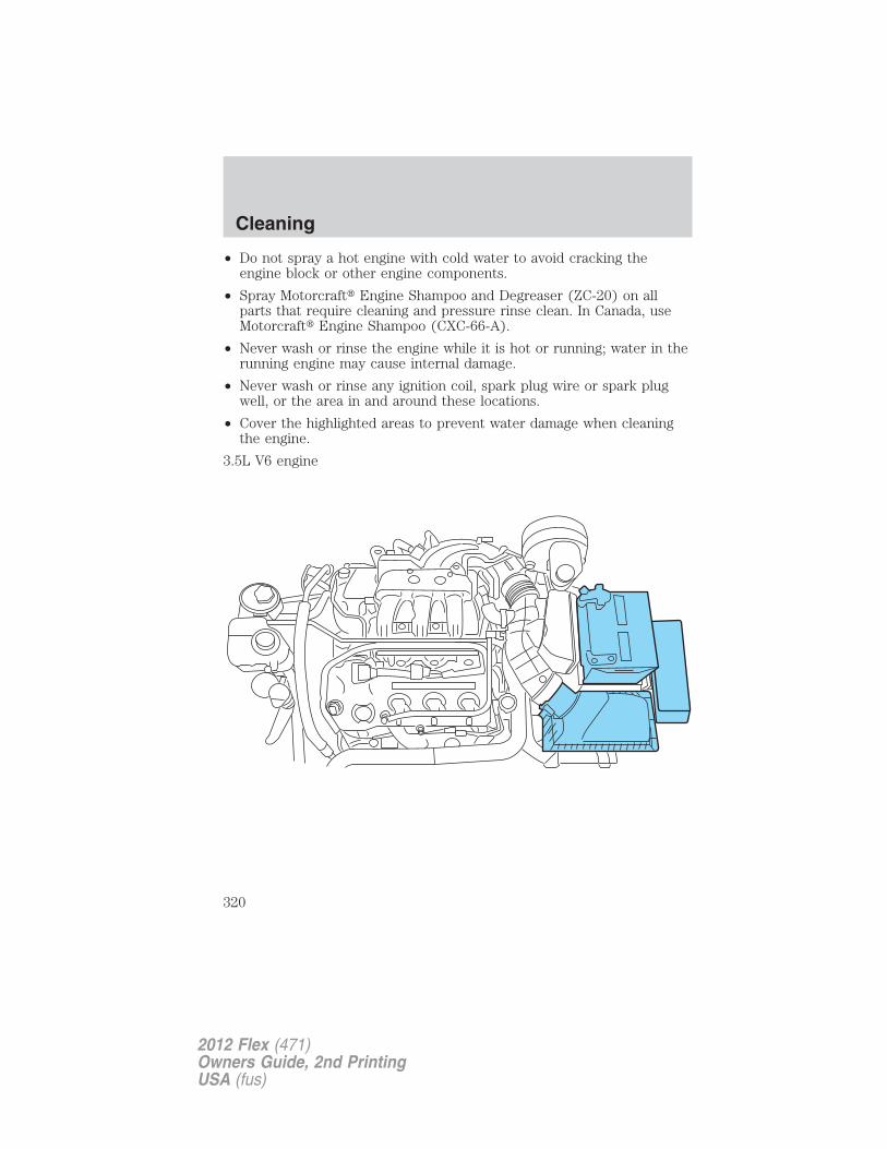
• Do not spray a hot engine with cold water to avoid cracking theengine block or other engine components.
• Spray Motorcraft� Engine Shampoo and Degreaser (ZC-20) on allparts that require cleaning and pressure rinse clean. In Canada, useMotorcraft� Engine Shampoo (CXC-66-A).
• Never wash or rinse the engine while it is hot or running; water in therunning engine may cause internal damage.
• Never wash or rinse any ignition coil, spark plug wire or spark plugwell, or the area in and around these locations.
• Cover the highlighted areas to prevent water damage when cleaningthe engine.
3.5L V6 engine
Cleaning
320
2012 Flex (471)Owners Guide, 2nd PrintingUSA (fus)
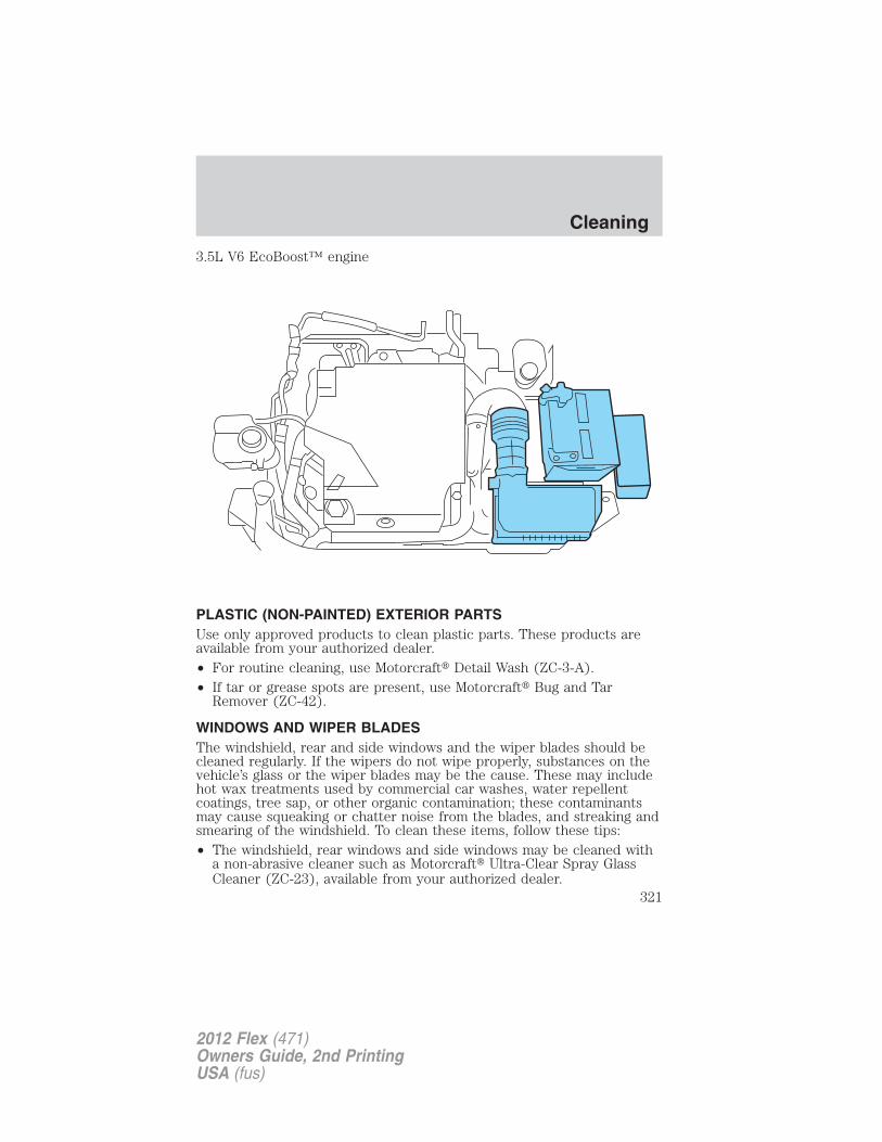
3.5L V6 EcoBoost™ engine
PLASTIC (NON-PAINTED) EXTERIOR PARTSUse only approved products to clean plastic parts. These products areavailable from your authorized dealer.• For routine cleaning, use Motorcraft� Detail Wash (ZC-3-A).• If tar or grease spots are present, use Motorcraft� Bug and Tar
Remover (ZC-42).
WINDOWS AND WIPER BLADESThe windshield, rear and side windows and the wiper blades should becleaned regularly. If the wipers do not wipe properly, substances on thevehicle’s glass or the wiper blades may be the cause. These may includehot wax treatments used by commercial car washes, water repellentcoatings, tree sap, or other organic contamination; these contaminantsmay cause squeaking or chatter noise from the blades, and streaking andsmearing of the windshield. To clean these items, follow these tips:• The windshield, rear windows and side windows may be cleaned with
a non-abrasive cleaner such as Motorcraft� Ultra-Clear Spray GlassCleaner (ZC-23), available from your authorized dealer.
Cleaning
321
2012 Flex (471)Owners Guide, 2nd PrintingUSA (fus)
• The wiper blades can be cleaned with isopropyl (rubbing) alcohol orMotorcraft� Premium Windshield Washer Concentrate (ZC-32-A) inthe U.S., or Premium Quality Windshield Washer Fluid [CXC-37-(A, B,D, or F)] in Canada, available from your authorized dealer. Thiswasher fluid contains special solution in addition to alcohol whichhelps to remove the hot wax deposited on the wiper blade andwindshield from automated car wash facilities. Be sure to replacewiper blades when they appear worn or do not function properly.
• Do not use abrasives, as they may cause scratches.
• Do not use fuel, kerosene, or paint thinner to clean any parts.
If you cannot remove those streaks after cleaning with the glass cleaneror if the wipers chatter and move in a jerky motion, clean the outersurface of the windshield and the wiper blades using a sponge or softcloth with a neutral detergent or mild-abrasive cleaning solution. Aftercleaning, rinse the windshield and wiper blades with clean water. Thewindshield is clean if beads do not form when you rinse the windshieldwith water.
Do not use sharp objects, such as a razor blade, to clean the
inside of the rear window or to remove decals, as it may cause
damage to the rear window defroster’s heated grid lines.
INSTRUMENT PANEL/INTERIOR TRIM AND CLUSTER LENS
Clean the instrument panel, interior trim areas and cluster lens with aclean, damp, white cotton cloth, then use a clean and dry white cottoncloth to dry these areas.
• Avoid cleaners or polishes that increase the gloss of the upper portionof the instrument panel. The dull finish in this area helps protect thedriver from undesirable windshield reflection.
• Be certain to wash or wipe your hands clean if you have been incontact with certain products such as insect repellent and suntanlotion in order to avoid possible damage to the interior paintedsurfaces.
• Do not use household or glass cleaners as these may damage thefinish of the instrument panel, interior trim and cluster lens.
• Do not allow air fresheners and hand sanitizers to spill on interiorsurfaces. If a spill occurs, wipe off immediately. Damage may not becovered by your warranty.
Cleaning
322
2012 Flex (471)Owners Guide, 2nd PrintingUSA (fus)
WARNING: Do not use chemical solvents or strong detergentswhen cleaning the steering wheel or instrument panel to avoid
contamination of the airbag system.
If a staining liquid like coffee/juice has been spilled on the instrumentpanel or on interior trim surfaces, clean as follows:1. Wipe up spilled liquid using a clean, white, cotton cloth.2. Wipe the surface with a damp, clean, white cotton cloth. For morethorough cleaning, use a mild soap and water solution. If the spot cannotbe completely cleaned by this method, the area may be cleaned using acommercially available cleaning product designed for automotiveinteriors.
3. If necessary, apply more soap and water solution or cleaning productto a clean, white, cotton cloth and press the cloth onto the soiledarea–allow this to set at room temperature for 30 minutes.
4. Remove the soaked cloth, and if it is not soiled badly, use this cloth toclean the area by using a rubbing motion for 60 seconds.
5. Following this, wipe area dry with a clean, white, cotton cloth.
INTERIORFor fabric, carpets, cloth seats, safety belts and seats equipped with sideairbags:
• Remove dust and loose dirt with a vacuum cleaner.
• Remove light stains and soil with Motorcraft� Professional StrengthCarpet & Upholstery Cleaner (ZC-54).
• If grease or tar is present on the material, spot-clean the area firstwith Motorcraft� Spot and Stain Remover (ZC-14). In Canada, useMotorcraft� Multi-Purpose Cleaner (CXC-101).
• If a ring forms on the fabric after spot cleaning, clean the entire areaimmediately (but do not oversaturate) or the ring will set.
• Do not use household cleaning products or glass cleaners, which canstain and discolor the fabric and affect the flame retardant abilities ofthe seat materials.
WARNING: Do not use cleaning solvents, bleach or dye on thevehicle’s safety belts, as these actions may weaken the belt
webbing.
Cleaning
323
2012 Flex (471)Owners Guide, 2nd PrintingUSA (fus)
WARNING: On vehicles equipped with seat-mounted airbags, donot use chemical solvents or strong detergents. Such products
could contaminate the side-airbag system and affect performance ofthe side airbag in a collision.
LEATHER SEATS (IF EQUIPPED)• Remove dust and loose dirt with a vacuum cleaner.
• Clean spills and stains as quickly as possible.
• For routine cleaning, wipe the surface with a soft, damp cloth. Formore thorough cleaning, wipe the surface with a mild soap and watersolution. In Canada, use Motorcraft� Vinyl Cleaner (CXC-93). Dry thearea with a soft cloth.
• If the leather cannot be completely cleaned using a mild soap andwater solution, the leather may be cleaned using a commerciallyavailable leather cleaning product designed for automotive interiors.
• To check for compatibility, first test any cleaner or stain remover onan inconspicuous part of the leather.
• Do not use household cleaning products, alcohol solutions, solvents orcleaners intended for rubber, vinyl and plastics, or oil/petroleum-basedleather conditioners. These products may cause premature wearing ordamage to the leather.
UNDERBODYFlush the complete underside of your vehicle frequently. Keep body anddoor drain holes free from packed dirt.
Cleaning
324
2012 Flex (471)Owners Guide, 2nd PrintingUSA (fus)
FORD AND LINCOLN CAR CARE PRODUCTSYour Ford or Lincoln authorized dealer has many quality productsavailable to clean your vehicle and protect its finishes. These qualityproducts have been specifically engineered to fulfill your automotiveneeds; they are custom designed to complement the style andappearance of your vehicle. Each product is made from high qualitymaterials that meet or exceed rigid specifications. For best results, usethe following products or products of equivalent quality:
Motorcraft� Bug and Tar Remover (ZC-42)
Motorcraft� Custom Bright Metal Cleaner (ZC-15)
Motorcraft� Detail Wash (ZC-3-A)
Motorcraft� Dusting Cloth (ZC-24)
Motorcraft� Engine Shampoo and Degreaser (U.S. only) (ZC-20)
Motorcraft� Engine Shampoo (Canada only) (CXC-66-A)
Motorcraft� Multi-Purpose Cleaner (Canada only) (CXC-101)
Motorcraft� Premium Glass Cleaner (Canada only) (CXC-100)
Motorcraft� Premium Quality Windshield Washer Fluid (Canada only)[CXC-37-(A, B, D or F)]
Motorcraft� Premium Windshield Washer Concentrate (U.S. only)(ZC-32-A)
Motorcraft� Professional Strength Carpet & Upholstery Cleaner (ZC-54)
Motorcraft� Spot and Stain Remover (U.S. only) (ZC-14)
Motorcraft� Ultra-Clear Spray Glass Cleaner (ZC-23)
Motorcraft� Vinyl Cleaner (Canada only) (CXC-93)
Motorcraft� Wheel and Tire Cleaner (ZC-37-A)
Cleaning
325
2012 Flex (471)Owners Guide, 2nd PrintingUSA (fus)
SERVICE RECOMMENDATIONS
To help you service your vehicle, we provide scheduled maintenanceinformation which makes tracking routine service easy.
If your vehicle requires professional service, your authorized dealer canprovide the necessary parts and service. Check your Warranty Guide tofind out which parts and services are covered.
Use only recommended fuels, lubricants, fluids and service partsconforming to specifications. Motorcraft� parts are designed and built toprovide the best performance in your vehicle.
PRECAUTIONS WHEN SERVICING YOUR VEHICLE
• Do not work on a hot engine.
• Make sure that nothing gets caught in moving parts.
• Do not work on a vehicle with the engine running in an enclosedspace, unless you are sure you have enough ventilation.
• Keep all open flames and other burning material (such as cigarettes)away from the battery and all fuel related parts.
Working with the engine off
1. Set the parking brake and shift to P (Park).
2. Turn off the engine and remove the key.
3. Block the wheels.
Working with the engine on
WARNING: To reduce the risk of vehicle damage and/orpersonal burn injuries, do not start your engine with the air
cleaner removed and do not remove it while the engine is running.
1. Set the parking brake and shift to P (Park).
2. Block the wheels.
Maintenance and Specifications
326
2012 Flex (471)Owners Guide, 2nd PrintingUSA (fus)
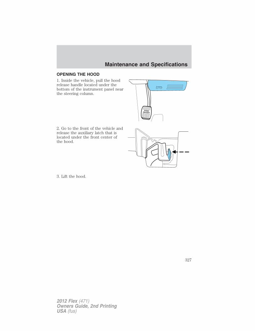
OPENING THE HOOD1. Inside the vehicle, pull the hoodrelease handle located under thebottom of the instrument panel nearthe steering column.
2. Go to the front of the vehicle andrelease the auxiliary latch that islocated under the front center ofthe hood.
3. Lift the hood.
Maintenance and Specifications
327
2012 Flex (471)Owners Guide, 2nd PrintingUSA (fus)
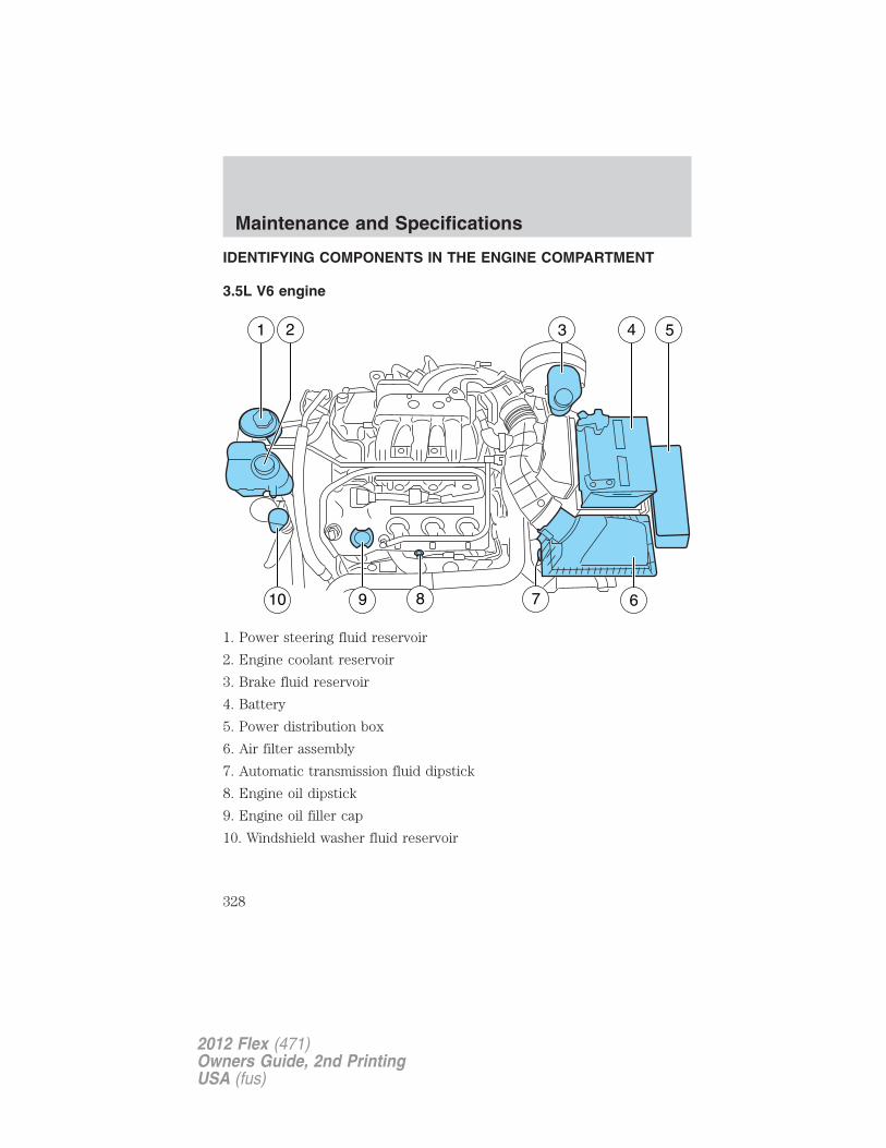
IDENTIFYING COMPONENTS IN THE ENGINE COMPARTMENT
3.5L V6 engine
1. Power steering fluid reservoir
2. Engine coolant reservoir
3. Brake fluid reservoir
4. Battery
5. Power distribution box
6. Air filter assembly
7. Automatic transmission fluid dipstick
8. Engine oil dipstick
9. Engine oil filler cap
10. Windshield washer fluid reservoir
1
10 9 8 7 6
2 3 4 5
Maintenance and Specifications
328
2012 Flex (471)Owners Guide, 2nd PrintingUSA (fus)
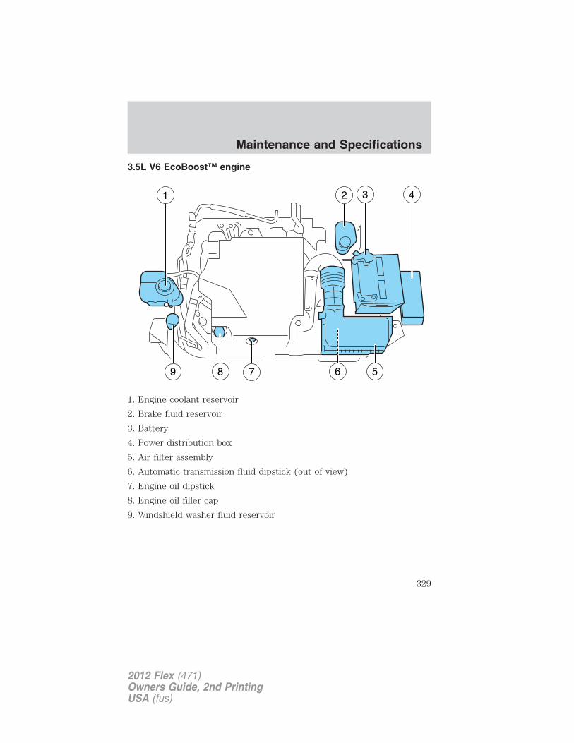
3.5L V6 EcoBoost™ engine
1. Engine coolant reservoir
2. Brake fluid reservoir
3. Battery
4. Power distribution box
5. Air filter assembly
6. Automatic transmission fluid dipstick (out of view)
7. Engine oil dipstick
8. Engine oil filler cap
9. Windshield washer fluid reservoir
Maintenance and Specifications
329
2012 Flex (471)Owners Guide, 2nd PrintingUSA (fus)
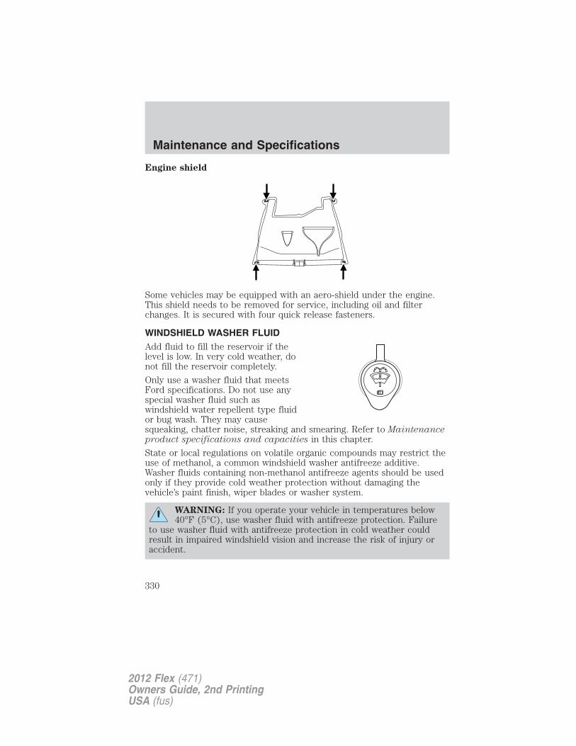
Engine shield
Some vehicles may be equipped with an aero-shield under the engine.This shield needs to be removed for service, including oil and filterchanges. It is secured with four quick release fasteners.
WINDSHIELD WASHER FLUIDAdd fluid to fill the reservoir if thelevel is low. In very cold weather, donot fill the reservoir completely.
Only use a washer fluid that meetsFord specifications. Do not use anyspecial washer fluid such aswindshield water repellent type fluidor bug wash. They may causesqueaking, chatter noise, streaking and smearing. Refer to Maintenanceproduct specifications and capacities in this chapter.
State or local regulations on volatile organic compounds may restrict theuse of methanol, a common windshield washer antifreeze additive.Washer fluids containing non-methanol antifreeze agents should be usedonly if they provide cold weather protection without damaging thevehicle’s paint finish, wiper blades or washer system.
WARNING: If you operate your vehicle in temperatures below40°F (5°C), use washer fluid with antifreeze protection. Failure
to use washer fluid with antifreeze protection in cold weather couldresult in impaired windshield vision and increase the risk of injury oraccident.
Maintenance and Specifications
330
2012 Flex (471)Owners Guide, 2nd PrintingUSA (fus)
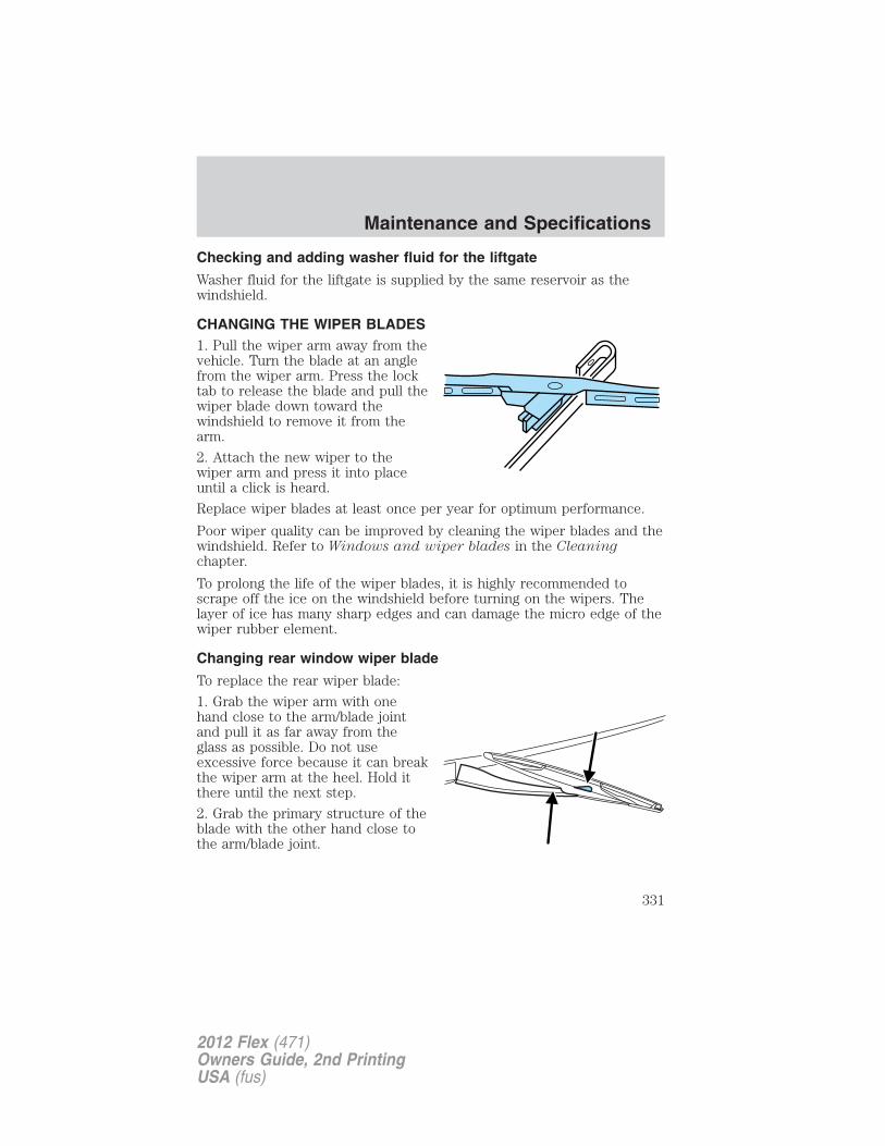
Checking and adding washer fluid for the liftgate
Washer fluid for the liftgate is supplied by the same reservoir as thewindshield.
CHANGING THE WIPER BLADES1. Pull the wiper arm away from thevehicle. Turn the blade at an anglefrom the wiper arm. Press the locktab to release the blade and pull thewiper blade down toward thewindshield to remove it from thearm.
2. Attach the new wiper to thewiper arm and press it into placeuntil a click is heard.
Replace wiper blades at least once per year for optimum performance.
Poor wiper quality can be improved by cleaning the wiper blades and thewindshield. Refer to Windows and wiper blades in the Cleaningchapter.
To prolong the life of the wiper blades, it is highly recommended toscrape off the ice on the windshield before turning on the wipers. Thelayer of ice has many sharp edges and can damage the micro edge of thewiper rubber element.
Changing rear window wiper blade
To replace the rear wiper blade:
1. Grab the wiper arm with onehand close to the arm/blade jointand pull it as far away from theglass as possible. Do not useexcessive force because it can breakthe wiper arm at the heel. Hold itthere until the next step.
2. Grab the primary structure of theblade with the other hand close tothe arm/blade joint.
Maintenance and Specifications
331
2012 Flex (471)Owners Guide, 2nd PrintingUSA (fus)
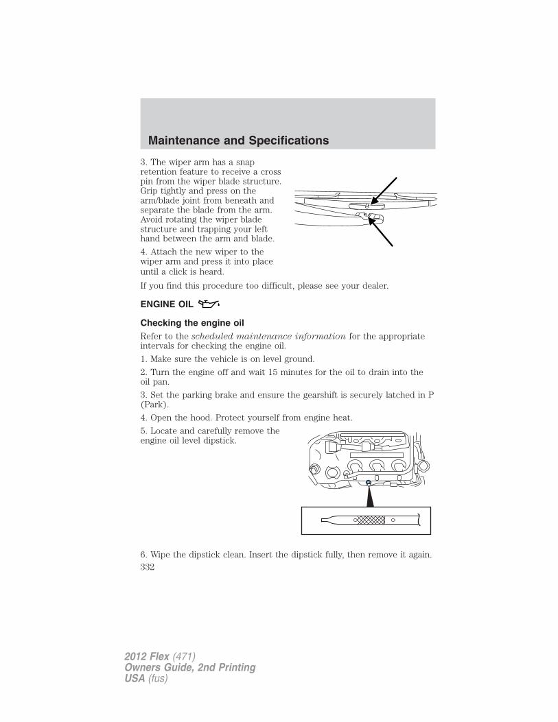
3. The wiper arm has a snapretention feature to receive a crosspin from the wiper blade structure.Grip tightly and press on thearm/blade joint from beneath andseparate the blade from the arm.Avoid rotating the wiper bladestructure and trapping your lefthand between the arm and blade.
4. Attach the new wiper to thewiper arm and press it into placeuntil a click is heard.
If you find this procedure too difficult, please see your dealer.
ENGINE OIL
Checking the engine oilRefer to the scheduled maintenance information for the appropriateintervals for checking the engine oil.
1. Make sure the vehicle is on level ground.
2. Turn the engine off and wait 15 minutes for the oil to drain into theoil pan.
3. Set the parking brake and ensure the gearshift is securely latched in P(Park).
4. Open the hood. Protect yourself from engine heat.
5. Locate and carefully remove theengine oil level dipstick.
6. Wipe the dipstick clean. Insert the dipstick fully, then remove it again.
Maintenance and Specifications
332
2012 Flex (471)Owners Guide, 2nd PrintingUSA (fus)
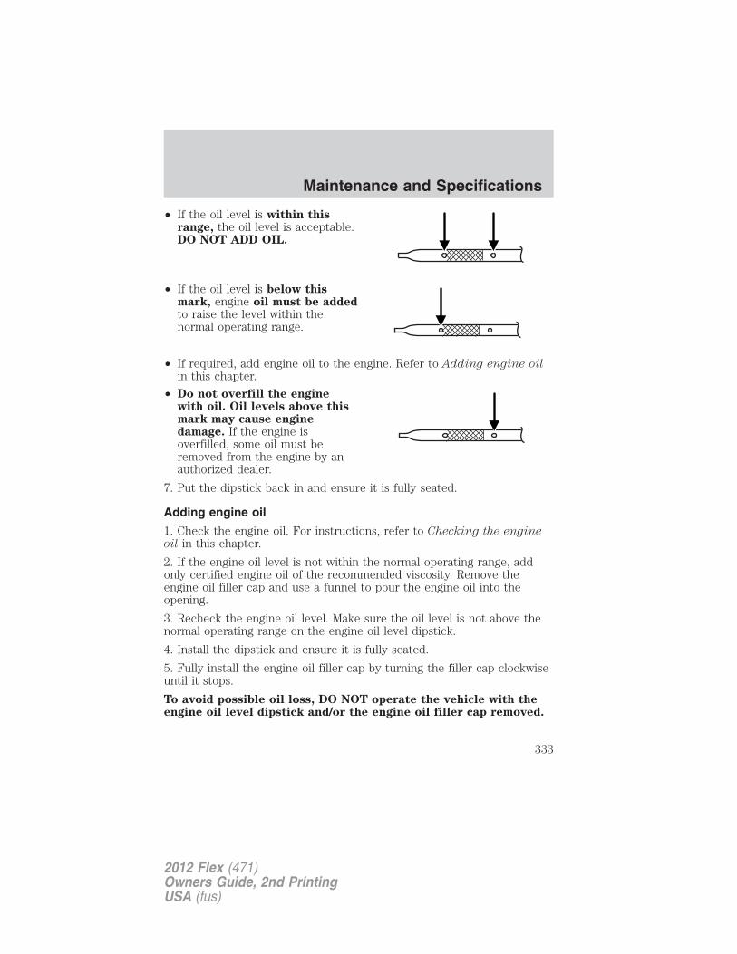
• If the oil level is within thisrange, the oil level is acceptable.DO NOT ADD OIL.
• If the oil level is below thismark, engine oil must be addedto raise the level within thenormal operating range.
• If required, add engine oil to the engine. Refer to Adding engine oilin this chapter.
• Do not overfill the enginewith oil. Oil levels above thismark may cause enginedamage. If the engine isoverfilled, some oil must beremoved from the engine by anauthorized dealer.
7. Put the dipstick back in and ensure it is fully seated.
Adding engine oil
1. Check the engine oil. For instructions, refer to Checking the engineoil in this chapter.
2. If the engine oil level is not within the normal operating range, addonly certified engine oil of the recommended viscosity. Remove theengine oil filler cap and use a funnel to pour the engine oil into theopening.
3. Recheck the engine oil level. Make sure the oil level is not above thenormal operating range on the engine oil level dipstick.
4. Install the dipstick and ensure it is fully seated.
5. Fully install the engine oil filler cap by turning the filler cap clockwiseuntil it stops.
To avoid possible oil loss, DO NOT operate the vehicle with theengine oil level dipstick and/or the engine oil filler cap removed.
Maintenance and Specifications
333
2012 Flex (471)Owners Guide, 2nd PrintingUSA (fus)
Engine oil and filter recommendations
3.5L V6 engine
Look for this certificationtrademark.
Use SAE 5W-20 engine oil
Only use oils certified for gasoline engines by the American PetroleumInstitute (API). An oil with this trademark symbol conforms to thecurrent engine and emission system protection standards and fueleconomy requirements of the International Lubricant Standardization andApproval Committee (ILSAC), comprised of U.S. and Japaneseautomobile manufacturers.
To protect your engine and engine’s warranty, use Motorcraft� SAE5W-20 or an equivalent SAE 5W-20 oil meeting Ford specificationWSS-M2C945-A. SAE 5W-20 oil provides optimum fuel economy and
durability performance meeting all requirements for your
vehicle’s engine. Refer to Maintenance product specifications and
capacities later in this section for more information.
Do not use supplemental engine oil additives, cleaners or other enginetreatments. They are unnecessary and could lead to engine damage thatis not covered by Ford warranty.
Change your engine oil according to the appropriate schedule listed inthe scheduled maintenance information.
Ford production and Motorcraft� replacement oil filters are designed foradded engine protection and long life. If a replacement oil filter is usedthat does not meet Ford material and design specifications, start-upengine noises or knock may be experienced.
It is recommended you use the appropriate Motorcraft� oil filter oranother with equivalent performance for your engine application.
Maintenance and Specifications
334
2012 Flex (471)Owners Guide, 2nd PrintingUSA (fus)
3.5L V6 EcoBoost™ engine
Look for this certificationtrademark.
Use SAE 5W-30 engine oil
Only use oils “Certified For Gasoline Engines” by the AmericanPetroleum Institute (API). An oil with this trademark symbol conformsto the current engine and emission system protection standards and fueleconomy requirements of the International Lubricant Standardization andApproval Committee (ILSAC), comprised of U.S. and Japaneseautomobile manufacturers.
To protect your engine and engine’s warranty, use Motorcraft� SAE5W-30 or an equivalent SAE 5W-30 oil meeting Ford specificationWSS-M2C946-A. Refer to Maintenance product specifications andcapacities later in this section for more information.
Do not use supplemental engine oil additives, cleaners or other enginetreatments. They are unnecessary and could lead to engine damage thatis not covered by Ford warranty.
Change your engine oil according to the appropriate schedule listed inthe scheduled maintenance information.
Ford production and Motorcraft� replacement oil filters are designed foradded engine protection and long life. If a replacement oil filter is usedthat does not meet Ford material and design specifications, start-upengine noises or knock may be experienced.
It is recommended you use the appropriate Motorcraft� oil filter oranother with equivalent performance for your engine application.
Maintenance and Specifications
335
2012 Flex (471)Owners Guide, 2nd PrintingUSA (fus)
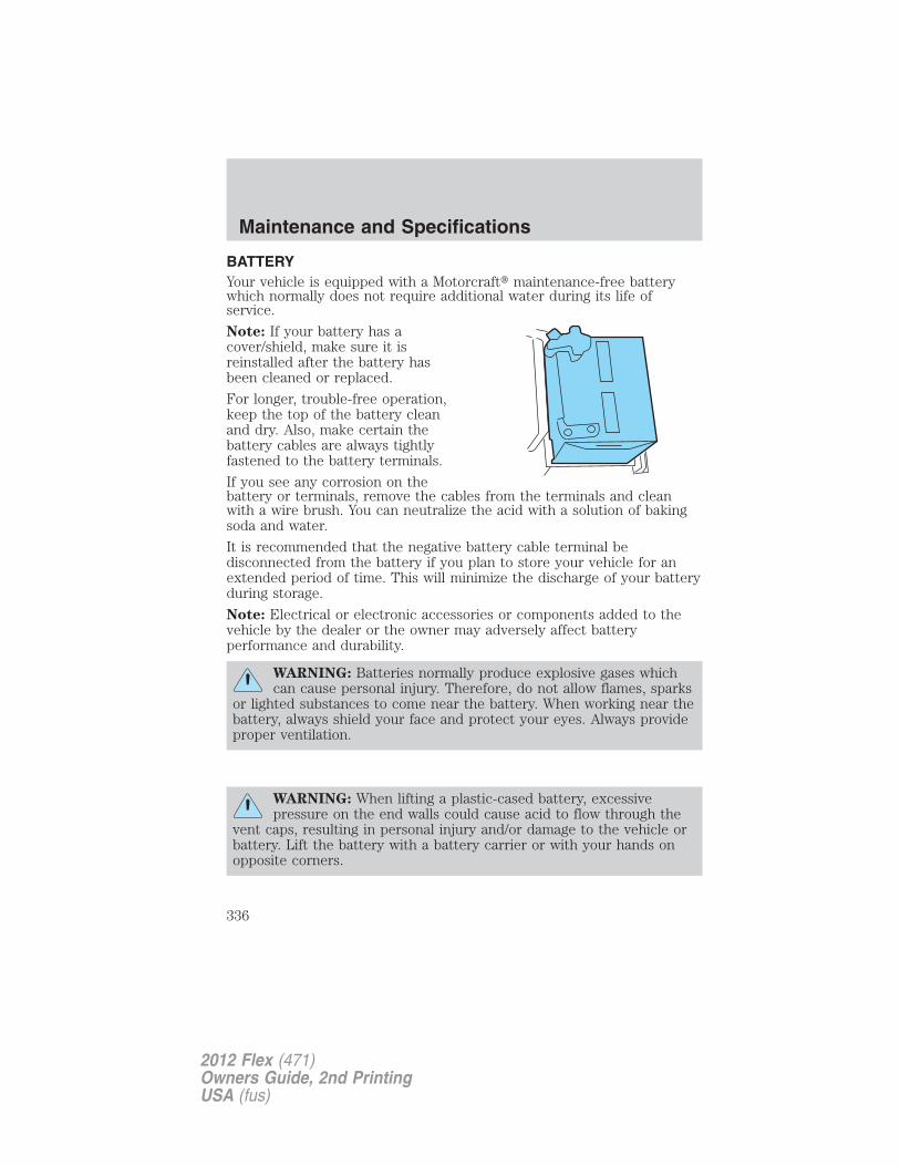
BATTERYYour vehicle is equipped with a Motorcraft� maintenance-free batterywhich normally does not require additional water during its life ofservice.
Note: If your battery has acover/shield, make sure it isreinstalled after the battery hasbeen cleaned or replaced.
For longer, trouble-free operation,keep the top of the battery cleanand dry. Also, make certain thebattery cables are always tightlyfastened to the battery terminals.
If you see any corrosion on thebattery or terminals, remove the cables from the terminals and cleanwith a wire brush. You can neutralize the acid with a solution of bakingsoda and water.
It is recommended that the negative battery cable terminal bedisconnected from the battery if you plan to store your vehicle for anextended period of time. This will minimize the discharge of your batteryduring storage.
Note: Electrical or electronic accessories or components added to thevehicle by the dealer or the owner may adversely affect batteryperformance and durability.
WARNING: Batteries normally produce explosive gases whichcan cause personal injury. Therefore, do not allow flames, sparks
or lighted substances to come near the battery. When working near thebattery, always shield your face and protect your eyes. Always provideproper ventilation.
WARNING: When lifting a plastic-cased battery, excessivepressure on the end walls could cause acid to flow through the
vent caps, resulting in personal injury and/or damage to the vehicle orbattery. Lift the battery with a battery carrier or with your hands onopposite corners.
Maintenance and Specifications
336
2012 Flex (471)Owners Guide, 2nd PrintingUSA (fus)
WARNING: Keep batteries out of reach of children. Batteriescontain sulfuric acid. Avoid contact with skin, eyes or clothing.
Shield your eyes when working near the battery to protect againstpossible splashing of acid solution. In case of acid contact with skin oreyes, flush immediately with water for a minimum of 15 minutes andget prompt medical attention. If acid is swallowed, call a physicianimmediately.
WARNING: Battery posts, terminals and related accessoriescontain lead and lead compounds. Note: Wash hands after
handling.
Because your vehicle’s engine is electronically controlled by a computer,some control conditions are maintained by power from the battery. Whenthe battery is disconnected or a new battery is installed, the engine mustrelearn its idle and fuel trim strategy for optimum driveability andperformance. To begin this process:
1. With the vehicle at a complete stop, set the parking brake.
2. Put the gearshift in P (Park), turn off all accessories and start theengine.
3. Run the engine until it reaches normal operating temperature.
4. Allow the engine to idle for at least one minute.
5. Turn the A/C on and allow the engine to idle for at least one minute.
6. Drive the vehicle to complete the relearning process.
• The vehicle may need to be driven 10 miles (16 km) or more torelearn the idle and fuel trim strategy.
• If you do not allow the engine to relearn its idle trim, the idlequality of your vehicle may be adversely affected until the idletrim is eventually relearned.
If the battery has been disconnected or a new battery has been installed,the clock and radio settings must be reset once the battery isreconnected.
Maintenance and Specifications
337
2012 Flex (471)Owners Guide, 2nd PrintingUSA (fus)
• Always dispose of automotivebatteries in a responsible manner.Follow your local authorizedstandards for disposal. Call yourlocal authorized recycling centerto find out more about recyclingautomotive batteries.
ENGINE COOLANT
Checking engine coolant
The concentration and level of engine coolant should be checked at theintervals listed in scheduled maintenance information. The coolantconcentration should be maintained at 50/50 coolant and distilled water.For best results, coolant concentration should be tested with arefractometer such as Rotunda tool 300-ROB75240E available from yourdealer. Ford does not recommend the use of hydrometers or coolant teststrips for measuring coolant concentration. The level of coolant shouldbe maintained at the FULL COLD level or within the COLD FILL RANGEin the coolant reservoir. If the level falls below, add coolant per theinstructions in the Adding engine coolant section.
Your vehicle was factory-filled with a 50/50 engine coolant and waterconcentration. If the concentration of coolant falls below 40% or above60%, the engine parts could become damaged or not work properly. A50/50 mixture of coolant and water provides the following:
• Improved freeze protection.
• Improved boiling protection.
• Protection against rust and other forms of corrosion.
• Proper function of calibrated gauges.
LE
AD
RE
TU
RN
RECYCLE
Maintenance and Specifications
338
2012 Flex (471)Owners Guide, 2nd PrintingUSA (fus)
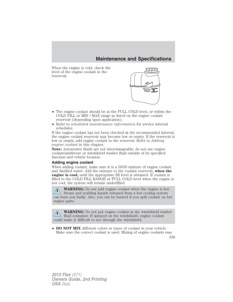
When the engine is cold, check thelevel of the engine coolant in thereservoir.
• The engine coolant should be at the FULL COLD level, or within theCOLD FILL or MIN / MAX range as listed on the engine coolantreservoir (depending upon application).
• Refer to scheduled maintenance information for service intervalschedules.
If the engine coolant has not been checked at the recommended interval,the engine coolant reservoir may become low or empty. If the reservoir islow or empty, add engine coolant to the reservoir. Refer to Addingengine coolant in this chapter.Note: Automotive fluids are not interchangeable; do not use enginecoolant/antifreeze or windshield washer fluid outside of its specifiedfunction and vehicle location.
Adding engine coolantWhen adding coolant, make sure it is a 50/50 mixture of engine coolantand distilled water. Add the mixture to the coolant reservoir, when theengine is cool, until the appropriate fill level is obtained. If coolant isfilled to the COLD FILL RANGE or FULL COLD level when the engine isnot cool, the system will remain underfilled.
WARNING: Do not add engine coolant when the engine is hot.Steam and scalding liquids released from a hot cooling system
can burn you badly. Also, you can be burned if you spill coolant on hotengine parts.
WARNING: Do not put engine coolant in the windshield washerfluid container. If sprayed on the windshield, engine coolant
could make it difficult to see through the windshield.
• DO NOT MIX different colors or types of coolant in your vehicle.Make sure the correct coolant is used. Mixing of engine coolants may
Maintenance and Specifications
339
2012 Flex (471)Owners Guide, 2nd PrintingUSA (fus)
harm your engine’s cooling system. The use of an improper coolantmay harm engine and cooling system components and may void thewarranty. Refer to Maintenance product specifications andcapacities in this chapter.
Note: Do not use stop leak pellets or cooling system sealants/additivesas they can cause damage to the engine cooling and/or heating systems.This damage would not be covered under your vehicle’s warranty.• A large amount of water without engine coolant may be added, in case
of emergency, to reach a vehicle service location. In this instance, thecooling system must be drained, chemically cleaned with Motorcraft�Premium Cooling System Flush, and refilled with a 50/50 mixture ofengine coolant and distilled water as soon as possible. Water alone(without engine coolant) can cause engine damage from corrosion,overheating or freezing.
• Do not use alcohol, methanol, brine or any engine coolantsmixed with alcohol or methanol antifreeze (coolant). Alcoholand other liquids can cause engine damage from overheating orfreezing.
• Do not add extra inhibitors or additives to the coolant. Thesecan be harmful and compromise the corrosion protection of the enginecoolant.
For vehicles with overflow coolant systems with a non-pressurized capon the coolant recovery system, add coolant to the coolant recoveryreservoir when the engine is cool. Add the proper mixture of coolant anddistilled water to the FULL COLD level. For all other vehicles which havea coolant degas system with a pressurized cap, or if it is necessary toremove the coolant pressure relief cap on the radiator of a vehicle withan overflow system, follow these steps to add engine coolant.
WARNING: To reduce the risk of personal injury, make sure theengine is cool before unscrewing the coolant pressure relief cap.
The cooling system is under pressure; steam and hot liquid can comeout forcefully when the cap is loosened slightly.
Add the proper mixture of coolant and water to the cooling system byfollowing these steps:
1. Before you begin, turn the engine off and let it cool.
2. When the engine is cool, wrap a thick cloth around the coolantpressure relief cap on the coolant reservoir (a translucent plastic bottle).Slowly turn cap counterclockwise (left) until pressure begins to release.
Maintenance and Specifications
340
2012 Flex (471)Owners Guide, 2nd PrintingUSA (fus)
3. Step back while the pressure releases.
4. When you are sure that all the pressure has been released, use thecloth to turn it counterclockwise and remove the cap.
5. Fill the coolant reservoir slowly with the proper coolant mixture, towithin the COLD FILL RANGE or the FULL COLD level on the reservoir.If you removed the radiator cap in an overflow system, fill the radiatoruntil the coolant is visible and radiator is almost full.
6. Replace the cap. Turn until tightly installed. Cap must be tightlyinstalled to prevent coolant loss.
After any coolant has been added, check the coolant concentration (referto Checking engine coolant). If the concentration is not 50/50, drainsome coolant and adjust the concentration. It may take several drainsand additions to obtain a 50/50 coolant concentration.
Whenever coolant has been added, the coolant level in the coolantreservoir should be checked the next few times you drive the vehicle. Ifnecessary, add enough 50/50 concentration of engine coolant anddistilled water to bring the liquid level to the proper level.
If you have to add more than 1.0 quart (1.0 liter) of engine coolant permonth, have your authorized dealer check the engine cooling system.Your cooling system may have a leak. Operating an engine with a lowlevel of coolant can result in engine overheating and possible enginedamage.
Recycled engine coolantFord Motor Company does NOT recommend the use of recycled enginecoolant since a Ford-approved recycling process is not yet available.
Used engine coolant should be disposed of in an appropriatemanner. Follow your community’s regulations and standards for recyclingand disposing of automotive fluids.
Coolant refill capacityTo find out how much fluid your vehicle’s cooling system can hold, referto Maintenance product specifications and capacities in this chapter.
Fill your engine coolant reservoir as outlined previously in the Addingengine coolant section.
Maintenance and Specifications
341
2012 Flex (471)Owners Guide, 2nd PrintingUSA (fus)
Severe climatesIf you drive in extremely cold climates:• It may be necessary to increase the coolant concentration
above 50%.
• NEVER increase the coolant concentration above 60%.
• A coolant concentration of 60% will provide improved freezepoint protection. Increased engine coolant concentrationsabove 60% will decrease the overheat protectioncharacteristics of the engine coolant and may cause enginedamage.
• If available, refer to the chart on the coolant container toensure the coolant concentration in your vehicle will provideadequate freeze protection at the temperatures in which youdrive in the winter months.
If you drive in extremely hot climates:
• It is still necessary to maintain the coolant concentrationabove 40%.
• NEVER decrease the coolant concentration below 40%.
• Decreased engine coolant concentrations below 40% willdecrease the corrosion/freeze protection characteristics of theengine coolant and may cause engine damage.
• If available, refer to the chart on the coolant container toensure the coolant concentration in your vehicle will provideadequate protection at the temperatures in which you drive.
Vehicles driven year-round in non-extreme climates should use a 50/50mixture of engine coolant and distilled water for optimum cooling systemand engine protection.
Engine fluid temperature management (EcoBoost™ engine only)Your vehicle has been designed to pull a trailer, but because of the addedload, the vehicle’s engine may temporarily reach higher temperaturesduring severe operating conditions such as ascending a long or steepgrade while pulling a trailer in hot ambient temperatures.
At this time, you may notice your engine coolant temperature gaugeneedle move toward the H and the POWER REDUCED TO LOWERTEMP message may appear on the message center.
You may notice a reduction in the vehicle’s speed caused by reducedengine power. Your vehicle has been designed to enter this mode if
Maintenance and Specifications
342
2012 Flex (471)Owners Guide, 2nd PrintingUSA (fus)
certain high temperature/high load conditions take place in order tomanage the engine’s fluid temperatures. The amount of speed reductionwill depend on the vehicle loading, towing, grade, ambient temperature,and other factors. If this occurs, there is no need to pull off the road.The vehicle can continue to be driven while this message is active.
WARNING: To reduce the risk of collision and injury, beprepared that the vehicle speed may reduce and the vehicle may
not be able to accelerate with full power until the fluid temperaturesreduce.
The air conditioning may also cycle on and off during severe operatingconditions to protect overheating of the engine. When the engine coolanttemperature decreases to a more normal operating temperature, the airconditioning will turn on once again.
If you notice any of the following:
• the engine coolant temperature gauge moves fully into the red (hot)area
• the coolant temperature warning light illuminates
• the service engine soon indicator illuminates
1. Pull off the road as soon as safely possible and place the vehicle in P(Park).
2. Leave the engine running until the coolant temperature gauge needlemoves away from the H range. After several minutes, if this does nothappen, follow the remaining steps.
3. Turn the engine off and wait for it to cool before checking the coolantlevel.
WARNING: Never remove the coolant reservoir cap while theengine is running or hot.
4. If the coolant level is normal, you may restart your engine andcontinue on.
5. If the coolant is low, add coolant, restart the engine and take yourvehicle to an authorized dealer. See Adding engine coolant in thischapter for more information.
Refer to fail-safe cooling for additional information.
Maintenance and Specifications
343
2012 Flex (471)Owners Guide, 2nd PrintingUSA (fus)
What you should know about fail-safe cooling
If the engine coolant supply is depleted, this feature allows the vehicle tobe driven temporarily before incremental component damage is incurred.The “fail-safe” distance depends on ambient temperatures, vehicle loadand terrain.
How fail-safe cooling works
If the engine begins to overheat:
• The engine coolant temperature gauge will move to the red (hot)area.
• The coolant temperature warning light will illuminate.
• The service engine soon indicator will illuminate.
If the engine reaches a preset over-temperature condition, the enginewill automatically switch to alternating cylinder operation. Each disabledcylinder acts as an air pump and cools the engine.
When this occurs the vehicle will still operate. However:
• The engine power will be limited.
• The air conditioning system will be disabled.
Continued operation will increase the engine temperature and the enginewill completely shut down, causing steering and braking effort toincrease.
Once the engine temperature cools, the engine can be re-started. Takeyour vehicle to an authorized dealer as soon as possible to minimizeengine damage.
When fail-safe mode is activatedYou have limited engine power when in the fail-safe mode, so drive thevehicle with caution. The vehicle will not be able to maintain high-speedoperation and the engine will run rough. Remember that the engine iscapable of completely shutting down automatically to prevent enginedamage, therefore:
1. Pull off the road as soon as safely possible and turn off the engine.
2. Arrange for the vehicle to be taken to an authorized dealer.
3. If this is not possible, wait a short period for the engine to cool.
4. Check the coolant level and replenish if low.
Maintenance and Specifications
344
2012 Flex (471)Owners Guide, 2nd PrintingUSA (fus)
WARNING: Fail-safe mode is for use during emergencies only.Operate the vehicle in fail-safe mode only as long as necessary to
bring the vehicle to rest in a safe location and seek immediate repairs.When in fail-safe mode, the vehicle will have limited power, will not beable to maintain high-speed operation, and may completely shut downwithout warning, potentially losing engine power, power steering assist,and power brake assist, which may increase the possibility of a crashresulting in serious injury.
WARNING: Never remove the coolant reservoir cap while theengine is running or hot.
5. Re-start the engine and take your vehicle to an authorized dealer.Driving the vehicle without repairing the engine problemincreases the chance of engine damage. Take your vehicle to anauthorized dealer as soon as possible.
FUEL FILTERYour vehicle is equipped with a lifetime fuel filter that is integrated withthe fuel tank. Regular maintenance or replacement is not needed.
WHAT YOU SHOULD KNOW ABOUT AUTOMOTIVE FUELS
Important safety precautions
WARNING: Do not overfill the fuel tank. The pressure in anoverfilled tank may cause leakage and lead to fuel spray and fire.
WARNING: The fuel system may be under pressure. If you heara hissing sound near the fuel filler door, do not refuel until the
sound stops. Otherwise, fuel may spray out, which could cause seriouspersonal injury.
WARNING: Automotive fuels can cause serious injury or deathif misused or mishandled.
WARNING: Gasoline may contain benzene, which is acancer-causing agent.
Maintenance and Specifications
345
2012 Flex (471)Owners Guide, 2nd PrintingUSA (fus)
Observe the following guidelines when handling automotive fuel:
• Extinguish all smoking materialsand any open flames beforerefueling your vehicle.
• Always turn off the vehicle beforerefueling.
• Automotive fuels can be harmfulor fatal if swallowed. Fuel such as gasoline is highly toxic and ifswallowed can cause death or permanent injury. If fuel is swallowed,call a physician immediately, even if no symptoms are immediatelyapparent. The toxic effects of fuel may not be visible for hours.
• Avoid inhaling fuel vapors. Inhaling too much fuel vapor of any kindcan lead to eye and respiratory tract irritation. In severe cases,excessive or prolonged breathing of fuel vapor can cause seriousillness and permanent injury.
• Avoid getting fuel liquid in your eyes. If fuel is splashed in the eyes,remove contact lenses (if worn), flush with water for 15 minutes andseek medical attention. Failure to seek proper medical attention couldlead to permanent injury.
• Fuels can also be harmful if absorbed through the skin. If fuel issplashed on the skin and/or clothing, promptly remove contaminatedclothing and wash skin thoroughly with soap and water. Repeated orprolonged skin contact with fuel liquid or vapor causes skin irritation.
• Be particularly careful if you are taking “Antabuse” or other forms ofdisulfiram for the treatment of alcoholism. Breathing gasoline vapors,or skin contact could cause an adverse reaction. In sensitiveindividuals, serious personal injury or sickness may result. If fuel issplashed on the skin, promptly wash skin thoroughly with soap andwater. Consult a physician immediately if you experience an adversereaction.
WARNING: When refueling always shut the engine off andnever allow sparks or open flames near the filler neck. Never
smoke while refueling. Fuel vapor is extremely hazardous under certainconditions. Care should be taken to avoid inhaling excess fumes.
WARNING: The flow of fuel through a fuel pump nozzle canproduce static electricity, which can cause a fire if fuel is
pumped into an ungrounded fuel container.
Maintenance and Specifications
346
2012 Flex (471)Owners Guide, 2nd PrintingUSA (fus)
Refueling
WARNING: Fuel vapor burns violently and a fuel fire can causesevere injuries. To help avoid injuries to you and others:
• Read and follow all the instructions on the pump island;• Turn off your engine when you are refueling;• Do not smoke if you are near fuel or refueling your vehicle;• Keep sparks, flames and smoking materials away from fuel;• Stay outside your vehicle and do not leave the fuel pump unattended
when refueling your vehicle — this is against the law in some places;• Keep children away from the fuel pump; never let children pump
fuel.• Do not use personal electronic devices while refueling. It can ignite
fuel vapors.
Use the following guidelines to avoid electrostatic charge build-up whenfilling an ungrounded fuel container:• Place approved fuel container on the ground.• DO NOT fill a fuel container while it is in the vehicle (including the
cargo area).• Keep the fuel pump nozzle in contact with the fuel container while
filling.• DO NOT use a device that would hold the fuel pump handle in the fill
position.
Easy Fuel� “no cap” fuel systemYour fuel tank is equipped with an Easy Fuel� “no cap” fuel filler system.This allows you to simply open the fuel filler door and insert the fuelfiller nozzle into the fuel system. The Easy Fuel� system is self-sealingand protected against dust, dirt, water and snow/ice.When fueling your vehicle:1. Turn the engine off.2. Open the fuel filler door.3. Slowly insert the fuel filler nozzle fully into the fuel system, and leavethe nozzle fully inserted until you are done pumping. Pump fuel asnormal.
4. After you are done pumping fuel, slowly remove the fuel fillernozzle—allow about five seconds after pumping fuel before removing thefuel filler nozzle. This allows residual fuel to drain back into the fuel tankand not spill onto the vehicle.
Maintenance and Specifications
347
2012 Flex (471)Owners Guide, 2nd PrintingUSA (fus)
Note: A fuel spillage concern may occur if overfilling the fuel tank. Donot overfill the tank to the point that the fuel is able to bypass the fuelfiller nozzle. The overfilled fuel may run down the drain located belowand in front of the fuel filler door.
If the check fuel fill inlet lamp or CHECK FUEL FILL INLET messagecomes on, the fuel fill inlet may not have properly closed. The inlet mayhave stuck open or debris may be preventing the inlet from fully closing.At the next opportunity, safely pull off the road, turn off the engine,open the fuel filler door and remove any visible debris from the fuel fillopening. Insert either the fuel fill nozzle or the fuel fill funnel (seeRefilling with a portable fuel container for funnel location) providedwith the vehicle several times to dislodge any debris and/or allow theinlet to close properly. If this action corrects the problem, the check fuelfill inlet lamp or CHECK FUEL FILL INLET message may not resetimmediately. It may take several driving cycles for the check fuel fill inletlamp or CHECK FUEL FILL INLET message to turn off. A driving cycleconsists of an engine start-up (after four or more hours with the engineoff) followed by city/highway driving. Continuing to drive with the checkfuel fill inlet lamp or CHECK FUEL FILL INLET message on may causethe service engine soon lamp to turn on as well.
WARNING: The fuel system may be under pressure. If you heara hissing sound near the fuel filler door (Easy Fuel� “no cap”
fuel system), do not refuel until the sound stops. Otherwise, fuel mayspray out, which could cause serious personal injury.
Choosing the right fuelUse only UNLEADED fuel or UNLEADED fuel blended with a maximumof 10% ethanol. Do not use fuel ethanol (E85), diesel, methanol, leadedfuel or any other fuel. The use of leaded fuel is prohibited by law andcould damage your vehicle.
Your vehicle was not designed to use fuel or fuel additives with metalliccompounds, including manganese-based additives.
Note: Use of any fuel other than those recommended may causepowertrain damage, a loss of vehicle performance, and repairs may notbe covered under warranty.
Maintenance and Specifications
348
2012 Flex (471)Owners Guide, 2nd PrintingUSA (fus)
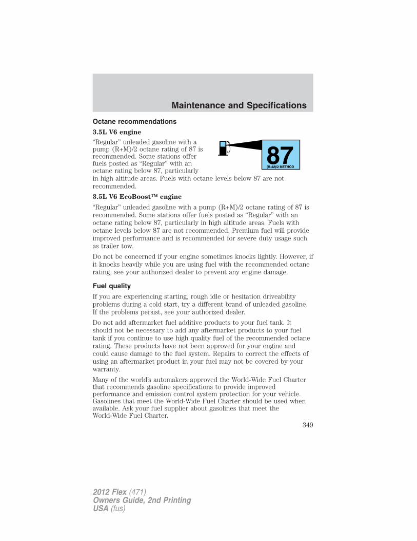
Octane recommendations
3.5L V6 engine
“Regular” unleaded gasoline with apump (R+M)/2 octane rating of 87 isrecommended. Some stations offerfuels posted as “Regular” with anoctane rating below 87, particularlyin high altitude areas. Fuels with octane levels below 87 are notrecommended.
3.5L V6 EcoBoost™ engine
“Regular” unleaded gasoline with a pump (R+M)/2 octane rating of 87 isrecommended. Some stations offer fuels posted as “Regular” with anoctane rating below 87, particularly in high altitude areas. Fuels withoctane levels below 87 are not recommended. Premium fuel will provideimproved performance and is recommended for severe duty usage suchas trailer tow.
Do not be concerned if your engine sometimes knocks lightly. However, ifit knocks heavily while you are using fuel with the recommended octanerating, see your authorized dealer to prevent any engine damage.
Fuel quality
If you are experiencing starting, rough idle or hesitation driveabilityproblems during a cold start, try a different brand of unleaded gasoline.If the problems persist, see your authorized dealer.
Do not add aftermarket fuel additive products to your fuel tank. Itshould not be necessary to add any aftermarket products to your fueltank if you continue to use high quality fuel of the recommended octanerating. These products have not been approved for your engine andcould cause damage to the fuel system. Repairs to correct the effects ofusing an aftermarket product in your fuel may not be covered by yourwarranty.
Many of the world’s automakers approved the World-Wide Fuel Charterthat recommends gasoline specifications to provide improvedperformance and emission control system protection for your vehicle.Gasolines that meet the World-Wide Fuel Charter should be used whenavailable. Ask your fuel supplier about gasolines that meet theWorld-Wide Fuel Charter.
87(R+M)/2 METHOD
Maintenance and Specifications
349
2012 Flex (471)Owners Guide, 2nd PrintingUSA (fus)
Cleaner air
Ford endorses the use of reformulated “cleaner-burning” gasolines toimprove air quality, per the recommendations in the Choosing the right
fuel section.
Running out of fuel
Avoid running out of fuel because this situation may have an adverseeffect on powertrain components.
If you have run out of fuel:
• You may need to cycle the ignition from off to on several times afterrefueling to allow the fuel system to pump the fuel from the tank tothe engine. With keyless ignition, just start the engine. Crank time willbe longer than usual.
• Normally, adding 1 gallon (3.8L) of fuel is enough to restart theengine. If the vehicle is out of fuel and on a steep grade, more than1 gallon (3.8L) may be required.
• The service engine soon indicator may come on. For moreinformation on the service engine soon indicator, refer to Warning
lights and chimes in the Instrument Cluster chapter.
Refilling with a portable fuel container
With the Easy Fuel� “no cap” fuel system, use the following directionswhen filling from a portable fuel container:
WARNING: Do not insert the nozzle of portable fuel containersor aftermarket funnels into the Easy Fuel� system. This could
damage the fuel system and its seal, and may cause fuel to run ontothe ground instead of filling the tank, which could result in seriouspersonal injury.
WARNING: Do not try to pry open or push open the Easy Fuel�system with foreign objects. This could damage the fuel system
and its seal and cause injury to you or others.
When filling the vehicle’s fuel tank from a portable fuel container, use thefunnel included with the vehicle.
Maintenance and Specifications
350
2012 Flex (471)Owners Guide, 2nd PrintingUSA (fus)
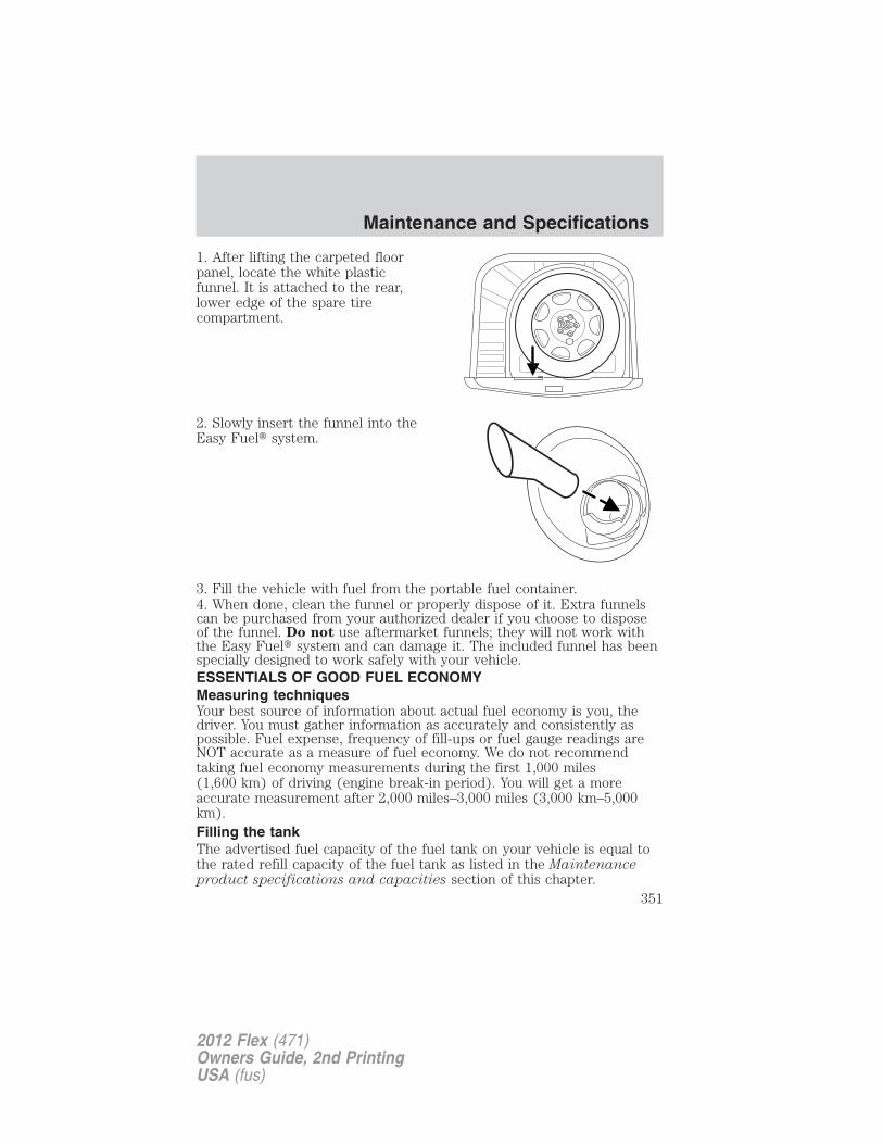
1. After lifting the carpeted floorpanel, locate the white plasticfunnel. It is attached to the rear,lower edge of the spare tirecompartment.
2. Slowly insert the funnel into theEasy Fuel� system.
3. Fill the vehicle with fuel from the portable fuel container.4. When done, clean the funnel or properly dispose of it. Extra funnelscan be purchased from your authorized dealer if you choose to disposeof the funnel. Do not use aftermarket funnels; they will not work withthe Easy Fuel� system and can damage it. The included funnel has beenspecially designed to work safely with your vehicle.ESSENTIALS OF GOOD FUEL ECONOMYMeasuring techniquesYour best source of information about actual fuel economy is you, thedriver. You must gather information as accurately and consistently aspossible. Fuel expense, frequency of fill-ups or fuel gauge readings areNOT accurate as a measure of fuel economy. We do not recommendtaking fuel economy measurements during the first 1,000 miles(1,600 km) of driving (engine break-in period). You will get a moreaccurate measurement after 2,000 miles–3,000 miles (3,000 km–5,000km).Filling the tankThe advertised fuel capacity of the fuel tank on your vehicle is equal tothe rated refill capacity of the fuel tank as listed in the Maintenanceproduct specifications and capacities section of this chapter.
Maintenance and Specifications
351
2012 Flex (471)Owners Guide, 2nd PrintingUSA (fus)
The advertised capacity is the amount of the indicated capacity and theempty reserve combined. Indicated capacity is the difference in theamount of fuel in a full tank and a tank when the fuel gauge indicatesempty. Empty reserve is the small amount of fuel remaining in the fueltank after the fuel gauge indicates empty.The amount of usable fuel in the empty reserve varies and shouldnot be relied upon to increase driving range. When refueling yourvehicle after the fuel gauge indicates empty, you might not beable to refuel the full amount of the advertised capacity of thefuel tank due to the empty reserve still present in the tank.
For consistent results when filling the fuel tank:• Turn the engine/ignition switch to the off position prior to refueling,
an error in the reading will result if the engine is left running.• Use the same filling rate setting (low — medium — high) each time
the tank is filled.
• Allow no more than two automatic click-offs when filling.
• Always use fuel with the recommended octane rating.
• Use a known quality gasoline, preferably a national brand.
• Have the vehicle loading and distribution the same every time.
Your results will be most accurate if your filling method is consistent.
Calculating fuel economy1. Fill the fuel tank completely and record the initial odometer reading(in miles or kilometers).
2. Each time you fill the tank, record the amount of fuel added (ingallons or liters).
3. After at least three to five tank fill-ups, fill the fuel tank and recordthe current odometer reading.
4. Subtract your initial odometer reading from the current odometerreading.
5. Follow one of the simple calculations in order to determine fueleconomy:
Calculation 1: Divide total miles traveled by total gallons used.
Calculation 2: Multiply liters used by 100, then divide by totalkilometers traveled.
Keep a record for at least one month and record the type of driving (cityor highway). This will provide an accurate estimate of the vehicle’s fuel
Maintenance and Specifications
352
2012 Flex (471)Owners Guide, 2nd PrintingUSA (fus)
economy under current driving conditions. Additionally, keeping recordsduring summer and winter will show how temperature impacts fueleconomy. In general, lower temperatures give lower fuel economy.
Driving style — good driving and fuel economy habitsGive consideration to the lists that follow and you may be able to changea number of variables and improve your fuel economy.
Habits• Smooth, moderate operation can yield up to 10% savings in fuel.• Steady speeds without stopping will usually give the best fuel
economy.• Idling for long periods of time (greater than one minute) may waste
fuel.• Anticipate stopping; slowing down may eliminate the need to stop.• Sudden or hard accelerations may reduce fuel economy.• Slow down gradually.• Driving at reasonable speeds (traveling at 55 mph [88 km/h] uses 15%
less fuel than traveling at 65 mph [105 km/h]).• Revving the engine before turning it off may reduce fuel economy.• Using the air conditioner or defroster may reduce fuel economy.• You may want to turn off the speed control in hilly terrain if
unnecessary shifting between the top gears occurs. Unnecessaryshifting of this type could result in reduced fuel economy.
• Warming up a vehicle on cold mornings is not required and mayreduce fuel economy.
• Resting your foot on the brake pedal while driving may reduce fueleconomy.
• Combine errands and minimize stop-and-go driving.
Maintenance• Keep tires properly inflated and use only recommended size.• Operating a vehicle with the wheels out of alignment will reduce fuel
economy.• Use recommended engine oil. Refer to Maintenance product
specifications and capacities in this chapter.
• Perform all regularly scheduled maintenance items. Follow therecommended maintenance schedule and owner maintenance checksfound in scheduled maintenance information.
Maintenance and Specifications
353
2012 Flex (471)Owners Guide, 2nd PrintingUSA (fus)
Conditions• Heavily loading a vehicle or towing a trailer may reduce fuel economy
at any speed.• Carrying unnecessary weight may reduce fuel economy (approximately
1 mpg [0.4 km/L] is lost for every 400 lb [180 kg] of weight carried).• Adding certain accessories to your vehicle (for example bug
deflectors, rollbars/light bars, running boards, ski racks) may reducefuel economy.
• Using fuel blended with alcohol may lower fuel economy.• Fuel economy may decrease with lower temperatures during the first
8–10 miles (12–16 km) of driving.• Driving on flat terrain offers improved fuel economy as compared to
driving on hilly terrain.• Transmissions give their best fuel economy when operated in the top
cruise gear and with steady pressure on the gas pedal.• Close windows for high speed driving.
EMISSION CONTROL SYSTEM
WARNING: Do not park, idle, or drive your vehicle in dry grassor other dry ground cover. The emission system heats up the
engine compartment and exhaust system, which can start a fire.
WARNING: Exhaust leaks may result in entry of harmful andpotentially lethal fumes into the passenger compartment. If you
smell exhaust fumes inside your vehicle, have your dealer inspect yourvehicle immediately. Do not drive if you smell exhaust fumes.
Your vehicle is equipped with various emission control components and acatalytic converter which will enable your vehicle to comply withapplicable exhaust emission standards. To make sure that the catalyticconverter and other emission control components continue to workproperly:• Use only the specified fuel listed.• Avoid running out of fuel.• Do not turn off the ignition while your vehicle is moving, especially at
high speeds.
• Have the items listed in scheduled maintenance informationperformed according to the specified schedule.
Maintenance and Specifications
354
2012 Flex (471)Owners Guide, 2nd PrintingUSA (fus)
The scheduled maintenance items listed in scheduled maintenanceinformation are essential to the life and performance of your vehicleand to its emissions system.If other than Ford, Motorcraft� or Ford-authorized parts are used formaintenance replacements or for service of components affectingemission control, such non-Ford parts should be equivalent to genuineFord Motor Company parts in performance and durability.
Illumination of the service engine soon indicator, charging systemwarning light or the temperature warning light, fluid leaks, strange odors,smoke or loss of engine power could indicate that the emission controlsystem is not working properly.
An improperly operating or damaged exhaust system may allow exhaustto enter the vehicle. Have a damaged or improperly operating exhaustsystem inspected and repaired immediately.
Do not make any unauthorized changes to your vehicle or engine. Bylaw, vehicle owners and anyone who manufactures, repairs, services,sells, leases, trades vehicles, or supervises a fleet of vehicles are notpermitted to intentionally remove an emission control device or preventit from working. Information about your vehicle’s emission system is onthe Vehicle Emission Control Information Decal located on or near theengine. This decal also lists engine displacement.
Please consult your Warranty Guide for complete emission warrantyinformation.
On-board diagnostics (OBD-II)Your vehicle is equipped with a computer that monitors the engine’semission control system. This system is commonly known as theon-board diagnostics system (OBD-II). The OBD-II system protects theenvironment by ensuring that your vehicle continues to meetgovernment emission standards. The OBD-II system also assists yourauthorized dealer in properly servicing your vehicle. When the serviceengine soon indicator illuminates, the OBD-II system has detecteda malfunction. Temporary malfunctions may cause the service enginesoon indicator to illuminate. Examples are:
1. The vehicle has run out of fuel—the engine may misfire or run poorly.
2. Poor fuel quality or water in the fuel—the engine may misfire or runpoorly.
3. The fuel fill inlet may not have been properly closed. See Easy Fuel�“no cap” fuel system in this chapter.
Maintenance and Specifications
355
2012 Flex (471)Owners Guide, 2nd PrintingUSA (fus)
4. Driving through deep water—the electrical system may be wet.
These temporary malfunctions can be corrected by filling the fuel tankwith good quality fuel, properly closing the fuel fill inlet or letting theelectrical system dry out. After three driving cycles without these or anyother temporary malfunctions present, the service engine soonindicator should stay off the next time the engine is started. A drivingcycle consists of a cold engine startup followed by mixed city/highwaydriving. No additional vehicle service is required.
If the service engine soon indicator remains on, have your vehicleserviced at the first available opportunity. Although some malfunctionsdetected by the OBD-II may not have symptoms that are apparent,continued driving with the service engine soon indicator on canresult in increased emissions, lower fuel economy, reduced engine andtransmission smoothness, and lead to more costly repairs.
Readiness for Inspection/Maintenance (I/M) testingSome state/provincial and local governments may haveInspection/Maintenance (I/M) programs to inspect the emission controlequipment on your vehicle. Failure to pass this inspection could preventyou from getting a vehicle registration. Your vehicle may not pass the I/Mtest if the service engine soon indicator is on or not workingproperly (bulb is burned out), or if the OBD-II system has determinedthat some of the emission control systems have not been properlychecked. In this case, the vehicle is considered not ready for I/M testing.
If the service engine soon indicator is on or the bulb does notwork, the vehicle may need to be serviced. Refer to On-boarddiagnostics (OBD-II) in this chapter.
If the vehicle’s engine or transmission has just been serviced, or thebattery has recently run down or been replaced, the OBD-II system mayindicate that the vehicle is not ready for I/M testing. To determine if thevehicle is ready for I/M testing, turn the ignition key to the on positionfor 15 seconds without cranking the engine. If the service enginesoon indicator blinks eight times, it means that the vehicle is notready for I/M testing; if the service engine soon indicator stays onsolid, it means that the vehicle is ready for I/M testing.
Maintenance and Specifications
356
2012 Flex (471)Owners Guide, 2nd PrintingUSA (fus)
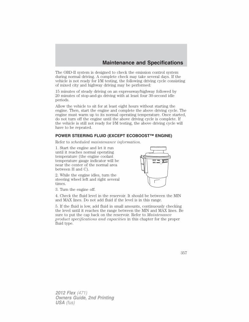
The OBD-II system is designed to check the emission control systemduring normal driving. A complete check may take several days. If thevehicle is not ready for I/M testing, the following driving cycle consistingof mixed city and highway driving may be performed:
15 minutes of steady driving on an expressway/highway followed by20 minutes of stop-and-go driving with at least four 30-second idleperiods.
Allow the vehicle to sit for at least eight hours without starting theengine. Then, start the engine and complete the above driving cycle. Theengine must warm up to its normal operating temperature. Once started,do not turn off the engine until the above driving cycle is complete. Ifthe vehicle is still not ready for I/M testing, the above driving cycle willhave to be repeated.
POWER STEERING FLUID (EXCEPT ECOBOOST™ ENGINE)
Refer to scheduled maintenance information.
1. Start the engine and let it rununtil it reaches normal operatingtemperature (the engine coolanttemperature gauge indicator will benear the center of the normal areabetween H and C).
2. While the engine idles, turn thesteering wheel left and right severaltimes.
3. Turn the engine off.
4. Check the fluid level in the reservoir. It should be between the MINand MAX lines. Do not add fluid if the level is in this range.
5. If the fluid is low, add fluid in small amounts, continuously checkingthe level until it reaches the range between the MIN and MAX lines. Besure to put the cap back on the reservoir. Refer to Maintenanceproduct specifications and capacities in this chapter for the properfluid type.
Maintenance and Specifications
357
2012 Flex (471)Owners Guide, 2nd PrintingUSA (fus)
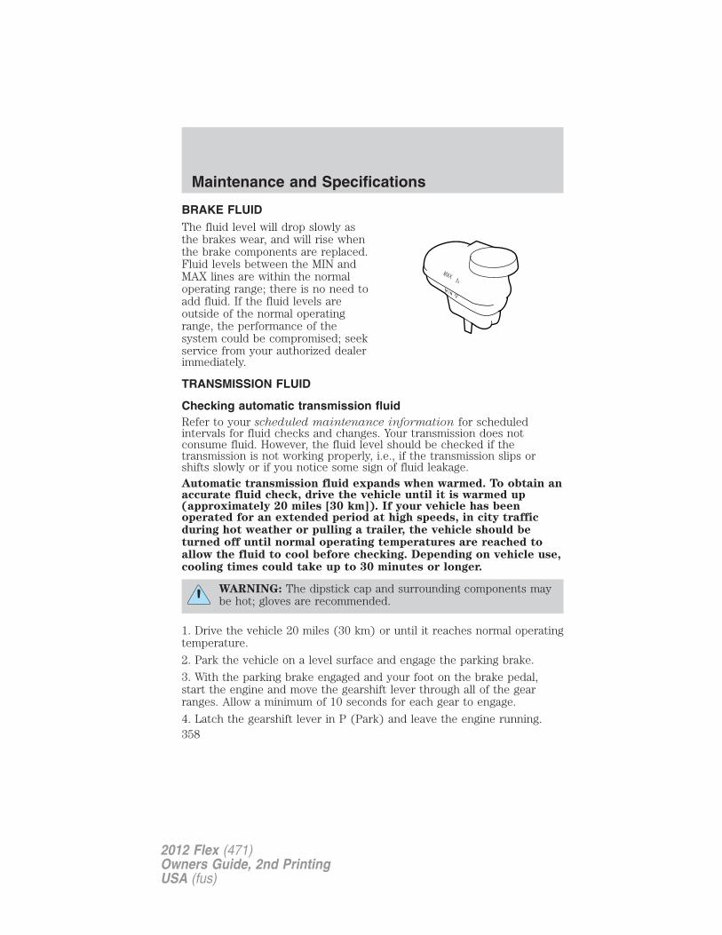
BRAKE FLUIDThe fluid level will drop slowly asthe brakes wear, and will rise whenthe brake components are replaced.Fluid levels between the MIN andMAX lines are within the normaloperating range; there is no need toadd fluid. If the fluid levels areoutside of the normal operatingrange, the performance of thesystem could be compromised; seekservice from your authorized dealerimmediately.
TRANSMISSION FLUID
Checking automatic transmission fluidRefer to your scheduled maintenance information for scheduledintervals for fluid checks and changes. Your transmission does notconsume fluid. However, the fluid level should be checked if thetransmission is not working properly, i.e., if the transmission slips orshifts slowly or if you notice some sign of fluid leakage.Automatic transmission fluid expands when warmed. To obtain anaccurate fluid check, drive the vehicle until it is warmed up(approximately 20 miles [30 km]). If your vehicle has beenoperated for an extended period at high speeds, in city trafficduring hot weather or pulling a trailer, the vehicle should beturned off until normal operating temperatures are reached toallow the fluid to cool before checking. Depending on vehicle use,cooling times could take up to 30 minutes or longer.
WARNING: The dipstick cap and surrounding components maybe hot; gloves are recommended.
1. Drive the vehicle 20 miles (30 km) or until it reaches normal operatingtemperature.
2. Park the vehicle on a level surface and engage the parking brake.
3. With the parking brake engaged and your foot on the brake pedal,start the engine and move the gearshift lever through all of the gearranges. Allow a minimum of 10 seconds for each gear to engage.
4. Latch the gearshift lever in P (Park) and leave the engine running.
Maintenance and Specifications
358
2012 Flex (471)Owners Guide, 2nd PrintingUSA (fus)
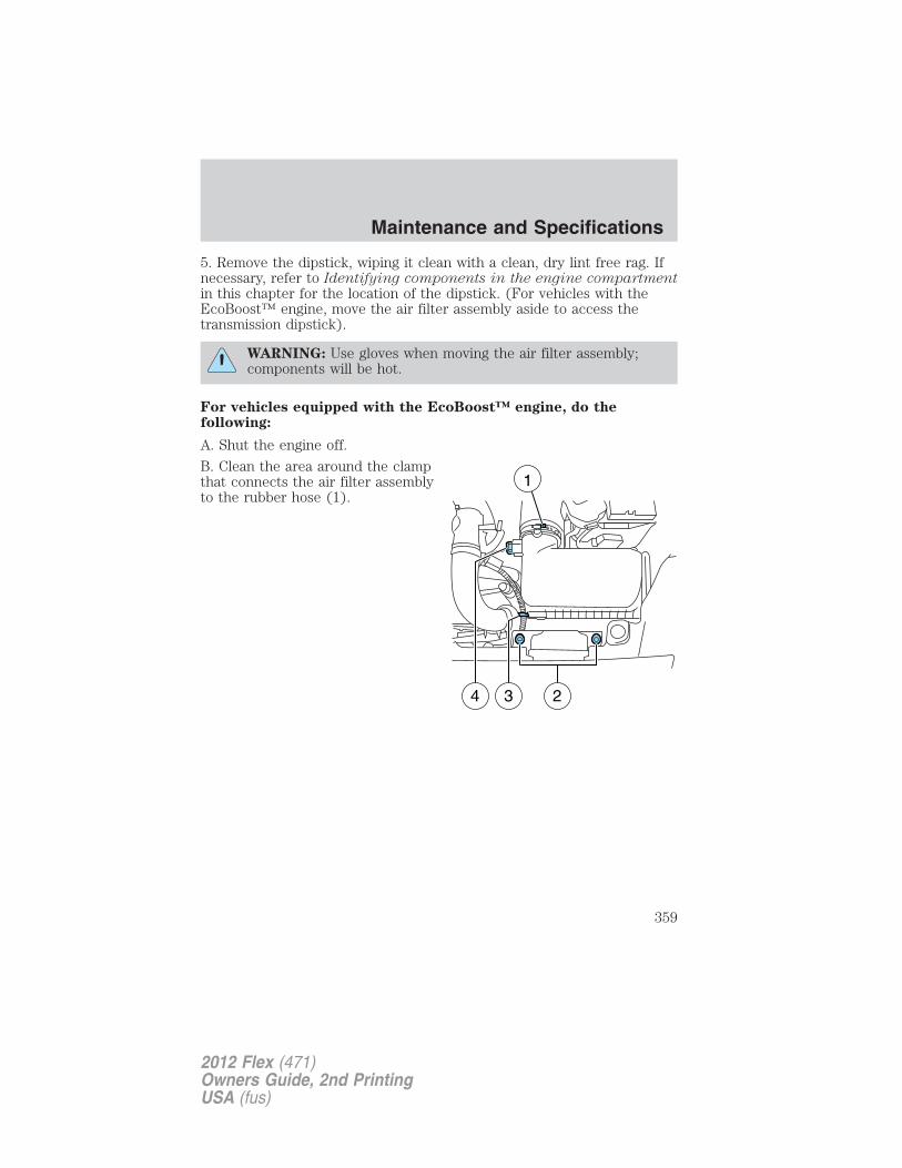
5. Remove the dipstick, wiping it clean with a clean, dry lint free rag. Ifnecessary, refer to Identifying components in the engine compartmentin this chapter for the location of the dipstick. (For vehicles with theEcoBoost™ engine, move the air filter assembly aside to access thetransmission dipstick).
WARNING: Use gloves when moving the air filter assembly;components will be hot.
For vehicles equipped with the EcoBoost™ engine, do thefollowing:
A. Shut the engine off.
B. Clean the area around the clampthat connects the air filter assemblyto the rubber hose (1).
1
4 3 2
Maintenance and Specifications
359
2012 Flex (471)Owners Guide, 2nd PrintingUSA (fus)
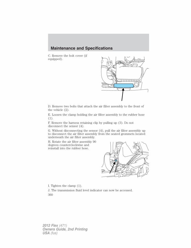
C. Remove the bolt cover (ifequipped).
D. Remove two bolts that attach the air filter assembly to the front ofthe vehicle (2).
E. Loosen the clamp holding the air filter assembly to the rubber hose(1).
F. Remove the harness retaining clip by pulling up (3). Do notdisconnect the sensor (4).
G. Without disconnecting the sensor (4), pull the air filter assembly upto disconnect the air filter assembly from the seated grommets locatedunderneath the air filter assembly.
H. Rotate the air filter assembly 90degrees counterclockwise andreinstall into the rubber hose.
I. Tighten the clamp (1).
J. The transmission fluid level indicator can now be accessed.
Maintenance and Specifications
360
2012 Flex (471)Owners Guide, 2nd PrintingUSA (fus)
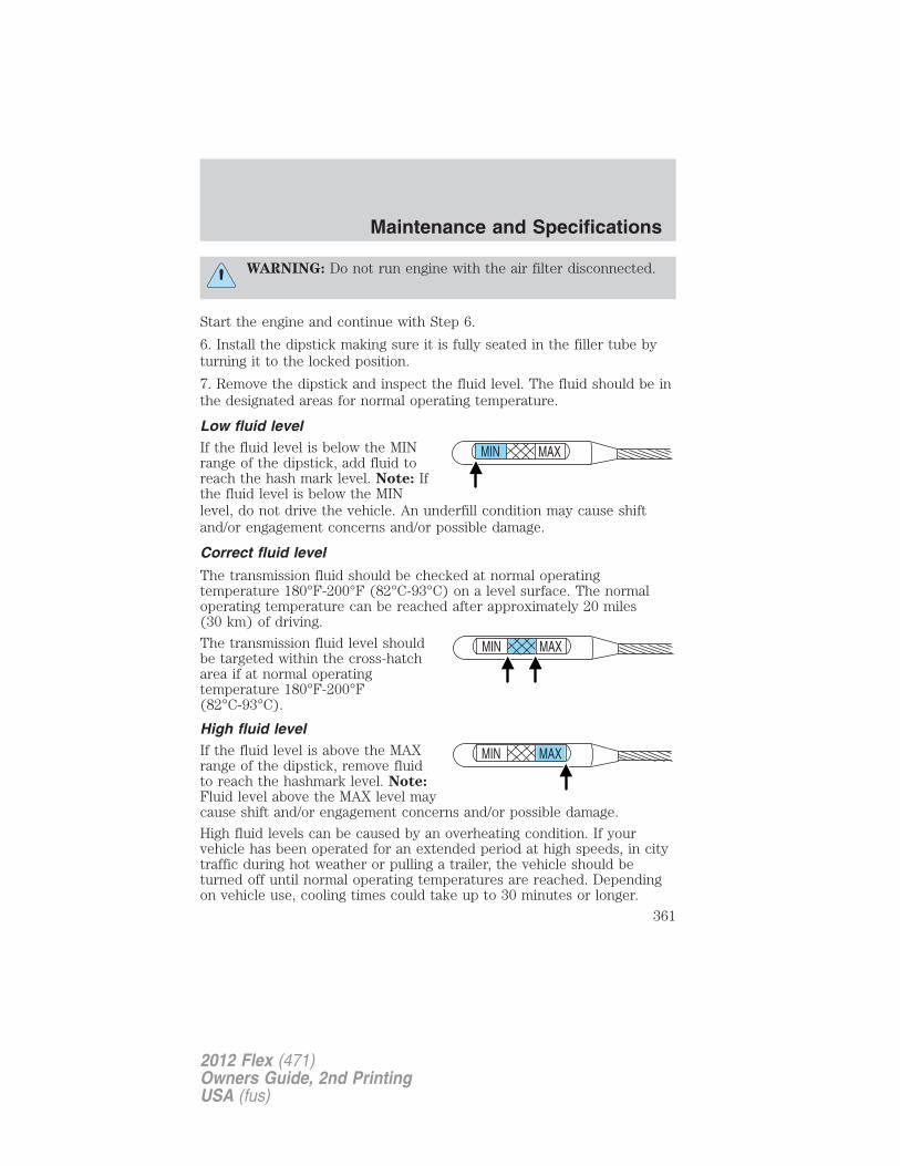
WARNING: Do not run engine with the air filter disconnected.
Start the engine and continue with Step 6.
6. Install the dipstick making sure it is fully seated in the filler tube byturning it to the locked position.
7. Remove the dipstick and inspect the fluid level. The fluid should be inthe designated areas for normal operating temperature.
Low fluid levelIf the fluid level is below the MINrange of the dipstick, add fluid toreach the hash mark level. Note: Ifthe fluid level is below the MINlevel, do not drive the vehicle. An underfill condition may cause shiftand/or engagement concerns and/or possible damage.
Correct fluid level
The transmission fluid should be checked at normal operatingtemperature 180°F-200°F (82°C-93°C) on a level surface. The normaloperating temperature can be reached after approximately 20 miles(30 km) of driving.
The transmission fluid level shouldbe targeted within the cross-hatcharea if at normal operatingtemperature 180°F-200°F(82°C-93°C).
High fluid levelIf the fluid level is above the MAXrange of the dipstick, remove fluidto reach the hashmark level. Note:Fluid level above the MAX level maycause shift and/or engagement concerns and/or possible damage.
High fluid levels can be caused by an overheating condition. If yourvehicle has been operated for an extended period at high speeds, in citytraffic during hot weather or pulling a trailer, the vehicle should beturned off until normal operating temperatures are reached. Dependingon vehicle use, cooling times could take up to 30 minutes or longer.
MAXMIN
MAXMIN
Maintenance and Specifications
361
2012 Flex (471)Owners Guide, 2nd PrintingUSA (fus)
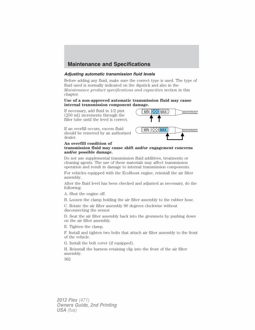
Adjusting automatic transmission fluid levels
Before adding any fluid, make sure the correct type is used. The type offluid used is normally indicated on the dipstick and also in theMaintenance product specifications and capacities section in thischapter.
Use of a non-approved automatic transmission fluid may causeinternal transmission component damage.
If necessary, add fluid in 1/2 pint(250 ml) increments through thefiller tube until the level is correct.
If an overfill occurs, excess fluidshould be removed by an authorizeddealer.
An overfill condition oftransmission fluid may cause shift and/or engagement concernsand/or possible damage.
Do not use supplemental transmission fluid additives, treatments orcleaning agents. The use of these materials may affect transmissionoperation and result in damage to internal transmission components.
For vehicles equipped with the EcoBoost engine, reinstall the air filterassembly.
After the fluid level has been checked and adjusted as necessary, do thefollowing:
A. Shut the engine off.
B. Loosen the clamp holding the air filter assembly to the rubber hose.
C. Rotate the air filter assembly 90 degrees clockwise withoutdisconnecting the sensor.
D. Seat the air filter assembly back into the grommets by pushing downon the air filter assembly.
E. Tighten the clamp.
F. Install and tighten two bolts that attach air filter assembly to the frontof the vehicle.
G. Install the bolt cover (if equipped).
H. Reinstall the harness retaining clip into the front of the air filterassembly.
MAXMIN
Maintenance and Specifications
362
2012 Flex (471)Owners Guide, 2nd PrintingUSA (fus)
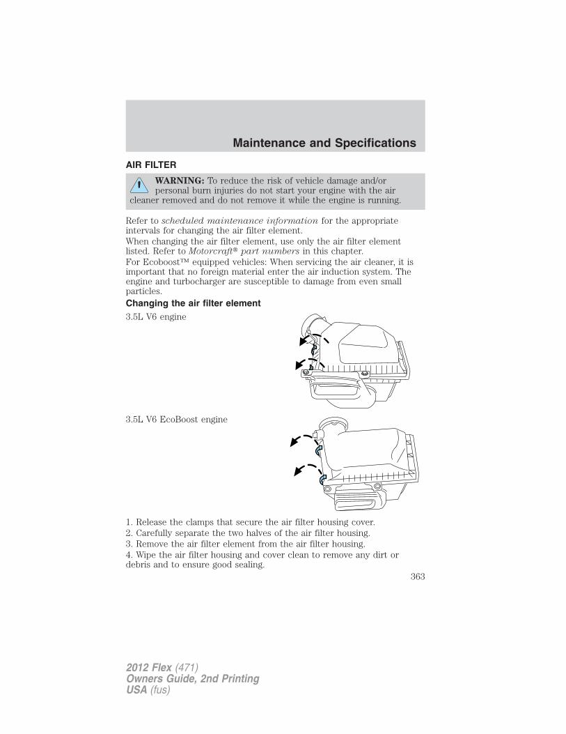
AIR FILTER
WARNING: To reduce the risk of vehicle damage and/orpersonal burn injuries do not start your engine with the air
cleaner removed and do not remove it while the engine is running.
Refer to scheduled maintenance information for the appropriateintervals for changing the air filter element.When changing the air filter element, use only the air filter elementlisted. Refer to Motorcraft� part numbers in this chapter.For Ecoboost™ equipped vehicles: When servicing the air cleaner, it isimportant that no foreign material enter the air induction system. Theengine and turbocharger are susceptible to damage from even smallparticles.Changing the air filter element3.5L V6 engine
3.5L V6 EcoBoost engine
1. Release the clamps that secure the air filter housing cover.2. Carefully separate the two halves of the air filter housing.3. Remove the air filter element from the air filter housing.4. Wipe the air filter housing and cover clean to remove any dirt ordebris and to ensure good sealing.
Maintenance and Specifications
363
2012 Flex (471)Owners Guide, 2nd PrintingUSA (fus)
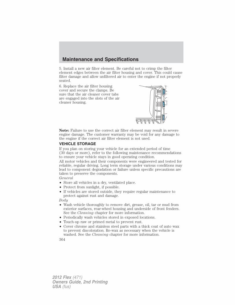
5. Install a new air filter element. Be careful not to crimp the filterelement edges between the air filter housing and cover. This could causefilter damage and allow unfiltered air to enter the engine if not properlyseated.
6. Replace the air filter housingcover and secure the clamps. Besure that the air cleaner cover tabsare engaged into the slots of the aircleaner housing.
Note: Failure to use the correct air filter element may result in severeengine damage. The customer warranty may be void for any damage tothe engine if the correct air filter element is not used.
VEHICLE STORAGEIf you plan on storing your vehicle for an extended period of time(30 days or more), refer to the following maintenance recommendationsto ensure your vehicle stays in good operating condition.All motor vehicles and their components were engineered and tested forreliable, regular driving. Long term storage under various conditions maylead to component degradation or failure unless specific precautions aretaken to preserve the components.General
• Store all vehicles in a dry, ventilated place.• Protect from sunlight, if possible.• If vehicles are stored outside, they require regular maintenance to
protect against rust and damage.Body
• Wash vehicle thoroughly to remove dirt, grease, oil, tar or mud fromexterior surfaces, rear-wheel housing and underside of front fenders.See the Cleaning chapter for more information.
• Periodically wash vehicles stored in exposed locations.• Touch-up raw or primed metal to prevent rust.• Cover chrome and stainless steel parts with a thick coat of auto wax
to prevent discoloration. Re-wax as necessary when the vehicle iswashed. See the Cleaning chapter for more information.
Maintenance and Specifications
364
2012 Flex (471)Owners Guide, 2nd PrintingUSA (fus)
• Lubricate all hood, door and trunk lid hinges, and latches with a lightgrade oil. See the Cleaning chapter for more information.
• Cover interior trim to prevent fading.
• Keep all rubber parts free from oil and solvents.
Engine
• The engine oil and filter should be changed prior to storage, as usedengine oil contain contaminates that may cause engine damage.
• Start the engine every 15 days. Run at fast idle until it reaches normaloperating temperature.
• With your foot on the brake, shift through all the gears while theengine is running.
Fuel system
• Fill the fuel tank with high-quality fuel until the first automatic shutoffof the fuel pump nozzle.
Note: During extended periods of vehicle storage (30 days or more),fuel may deteriorate due to oxidation. Add a quality gas stabilizerproduct to the vehicle fuel system whenever actual or expected storageperiods exceed 30 days. Follow the instructions on the additive label.The vehicle should then be operated at idle speed to circulate theadditive throughout the fuel system.
Cooling system
• Protect against freezing temperatures.
• When removing vehicle from storage, check coolant fluid level.Confirm there are no cooling system leaks, and fluid is at therecommended level.
Battery
• Check and recharge as necessary. Keep connections clean.
• If storing your vehicle for more than 30 days without recharging thebattery, it may be advisable to disconnect the battery cables to ensurebattery charge is maintained for quick starting.
Note: If battery cables are disconnected, it will be necessary to resetmemory features.
Maintenance and Specifications
365
2012 Flex (471)Owners Guide, 2nd PrintingUSA (fus)
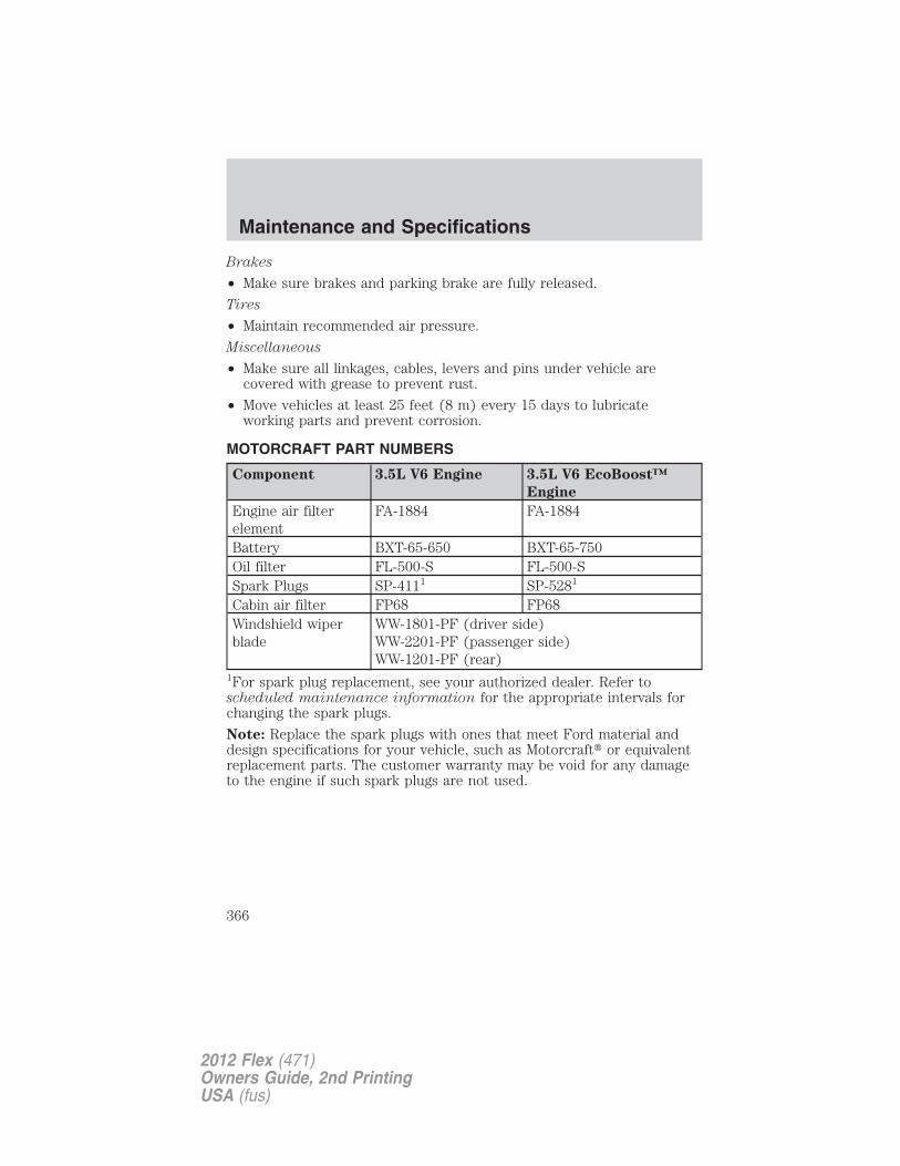
Brakes
• Make sure brakes and parking brake are fully released.
Tires
• Maintain recommended air pressure.
Miscellaneous
• Make sure all linkages, cables, levers and pins under vehicle arecovered with grease to prevent rust.
• Move vehicles at least 25 feet (8 m) every 15 days to lubricateworking parts and prevent corrosion.
MOTORCRAFT PART NUMBERS
Component 3.5L V6 Engine 3.5L V6 EcoBoost™
Engine
Engine air filterelement
FA-1884 FA-1884
Battery BXT-65-650 BXT-65-750Oil filter FL-500-S FL-500-SSpark Plugs SP-4111 SP-5281
Cabin air filter FP68 FP68Windshield wiperblade
WW-1801-PF (driver side)WW-2201-PF (passenger side)WW-1201-PF (rear)
1For spark plug replacement, see your authorized dealer. Refer toscheduled maintenance information for the appropriate intervals forchanging the spark plugs.
Note: Replace the spark plugs with ones that meet Ford material anddesign specifications for your vehicle, such as Motorcraft� or equivalentreplacement parts. The customer warranty may be void for any damageto the engine if such spark plugs are not used.
Maintenance and Specifications
366
2012 Flex (471)Owners Guide, 2nd PrintingUSA (fus)
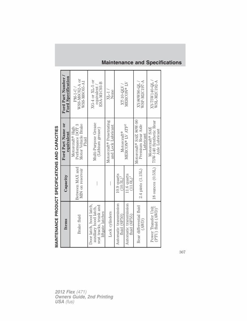
MA
INT
EN
AN
CE
PR
OD
UC
TS
PE
CIF
ICA
TIO
NS
AN
DC
APA
CIT
IES
Item
sC
ap
acit
yF
ord
Part
Nam
eo
req
uiv
ale
nt
Fo
rd
Part
Nu
mb
er
/F
ord
Sp
ecif
icati
on
Bra
kefl
uid
Bet
wee
nM
AX
and
MIN
onre
serv
oir
Mot
orcr
aft�
Hig
hP
erfo
rman
ceD
OT
3M
otor
Veh
icle
Bra
keF
luid
PM
-1-C
/W
SS-M
6C62
-Aor
WSS
-M6C
65-A
1
Doo
rla
tch,
hood
latc
h,au
xilia
ryho
odla
tch,
seat
trac
ks,
trun
kan
dlif
tgat
ela
tche
s
—M
ulti
-Pur
pose
Gre
ase
(Lit
hium
grea
se)
XG
-4or
XL
-5or
equi
vale
nt/
ESA
-M1C
93-B
Loc
kcy
linde
rs—
Mot
orcr
aft�
Pen
etra
ting
and
Loc
kL
ubri
cant
XL
-1/
Non
eA
utom
atic
tran
smis
sion
flui
d(6
F50
)10
.9qu
arts
(10.
3L)1
Mot
orcr
aft�
ME
RC
ON
�LV
AT
F2
XT-
10-Q
LV/
ME
RC
ON
�LV
Aut
omat
ictr
ansm
issi
onfl
uid
(6F
55)
11.6
quar
ts(1
1.0L
)1
Rea
rdi
ffer
enti
alfl
uid
(AW
D)
2.4
pint
s(1
.15L
)M
otor
craf
t�SA
E80
W-9
0P
rem
ium
Rea
rA
xle
Lub
rica
nt
XY-
80W
90-Q
L/
WSP
-M2C
197-
A
Pow
erT
rans
fer
Uni
t(P
TU
)fl
uid
(AW
D)5
18ou
nces
(0.5
3L)
Mot
orcr
aft�
SAE
75W
-140
Synt
heti
cR
ear
Axl
eL
ubri
cant
XY-
75W
140-
QL
/W
SL-M
2C19
2-A
Maintenance and Specifications
367
2012 Flex (471)Owners Guide, 2nd PrintingUSA (fus)
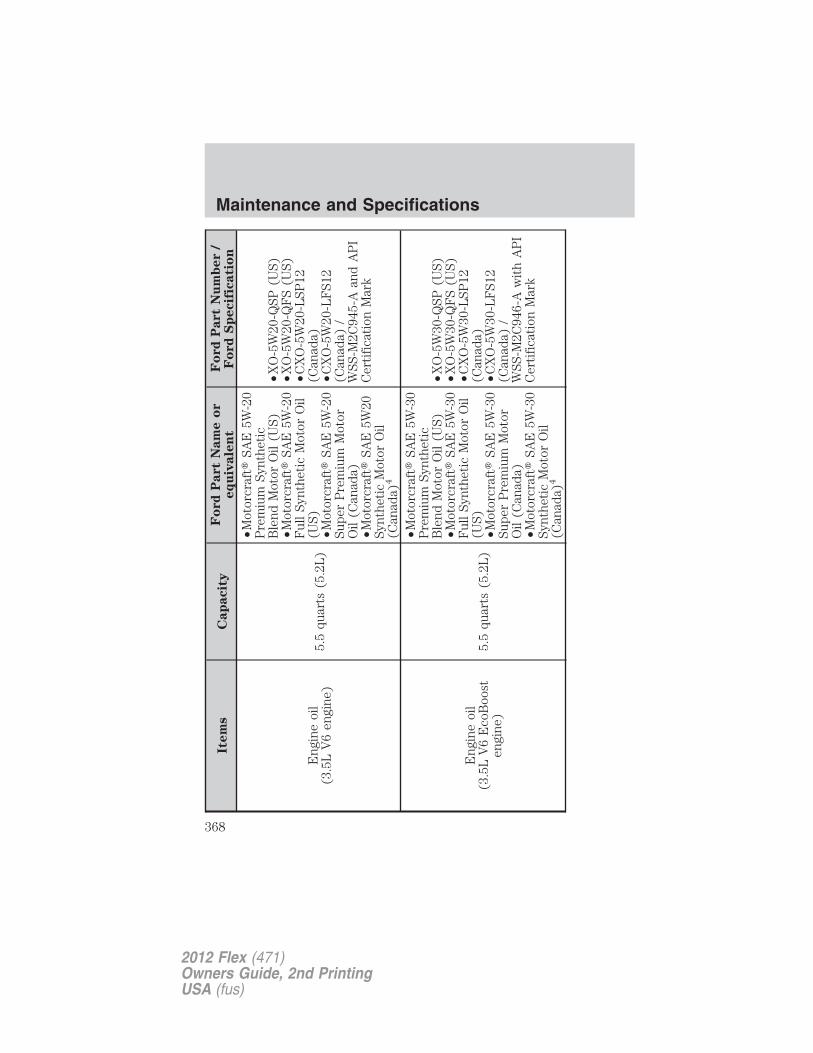
Item
sC
ap
acit
yF
ord
Part
Nam
eo
req
uiv
ale
nt
Fo
rd
Part
Nu
mb
er
/F
ord
Sp
ecif
icati
on
Eng
ine
oil
(3.5
LV
6en
gine
)5.
5qu
arts
(5.2
L)
•Mot
orcr
aft�
SAE
5W-2
0P
rem
ium
Synt
heti
cB
lend
Mot
orO
il(U
S)•M
otor
craf
t�SA
E5W
-20
Ful
lSy
nthe
tic
Mot
orO
il(U
S)•M
otor
craf
t�SA
E5W
-20
Supe
rP
rem
ium
Mot
orO
il(C
anad
a)•M
otor
craf
t�SA
E5W
20Sy
nthe
tic
Mot
orO
il(C
anad
a)4
•XO
-5W
20-Q
SP(U
S)•X
O-5
W20
-QF
S(U
S)•C
XO
-5W
20-L
SP12
(Can
ada)
•CX
O-5
W20
-LF
S12
(Can
ada)
/W
SS-M
2C94
5-A
and
AP
IC
erti
fica
tion
Mar
k
Eng
ine
oil
(3.5
LV
6E
coB
oost
engi
ne)
5.5
quar
ts(5
.2L
)
•Mot
orcr
aft�
SAE
5W-3
0P
rem
ium
Synt
heti
cB
lend
Mot
orO
il(U
S)•M
otor
craf
t�SA
E5W
-30
Ful
lSy
nthe
tic
Mot
orO
il(U
S)•M
otor
craf
t�SA
E5W
-30
Supe
rP
rem
ium
Mot
orO
il(C
anad
a)•M
otor
craf
t�SA
E5W
-30
Synt
heti
cM
otor
Oil
(Can
ada)
4
•XO
-5W
30-Q
SP(U
S)•X
O-5
W30
-QF
S(U
S)•C
XO
-5W
30-L
SP12
(Can
ada)
•CX
O-5
W30
-LF
S12
(Can
ada)
/W
SS-M
2C94
6-A
wit
hA
PI
Cer
tifi
cati
onM
ark
Maintenance and Specifications
368
2012 Flex (471)Owners Guide, 2nd PrintingUSA (fus)
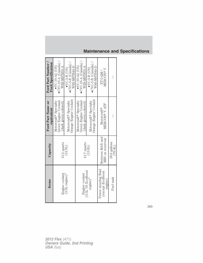
Item
sC
ap
acit
yF
ord
Part
Nam
eo
req
uiv
ale
nt
Fo
rd
Part
Nu
mb
er
/F
ord
Sp
ecif
icati
on
Eng
ine
cool
ant
(3.5
Len
gine
)313
.2qu
arts
(12.
5L)
Mot
orcr
aft�
Spec
ialt
yG
reen
Eng
ine
Coo
lant
(dar
kgr
een-
colo
red)
•VC
-10-
A2
(US)
•CV
C-1
0-A
(Can
ada)
/W
SS-M
97B
55-A
Mot
orcr
aft�
Spec
ialt
yO
rang
eE
ngin
eC
oola
nt
•VC
-3-B
(US)
•CV
C-3
-B(C
anad
a)/
WSS
-M97
B44
-D
Eng
ine
cool
ant
(3.5
LV
6E
coB
oost
engi
ne)3
13.7
quar
ts(1
3.0L
)
Mot
orcr
aft�
Spec
ialt
yG
reen
Eng
ine
Coo
lant
(dar
kgr
een-
colo
red)
•VC
-10-
A2
(US)
•CV
C-1
0-A
(Can
ada)
/W
SS-M
97B
55-A
Mot
orcr
aft�
Spec
ialt
yO
rang
eE
ngin
eC
oola
nt
•VC
-3-B
(US)
•CV
C-3
-B(C
anad
a)/
WSS
-M97
B44
-DP
ower
stee
ring
flui
d(e
xcep
tE
coB
oost
engi
ne)
Bet
wee
nM
AX
and
MIN
onre
serv
oir
Mot
orcr
aft�
ME
RC
ON
�V
AT
FX
T-5-
QM
/M
ER
CO
N�
V
Fue
lta
nk18
.6ga
llons
(70.
4L)
——
Maintenance and Specifications
369
2012 Flex (471)Owners Guide, 2nd PrintingUSA (fus)
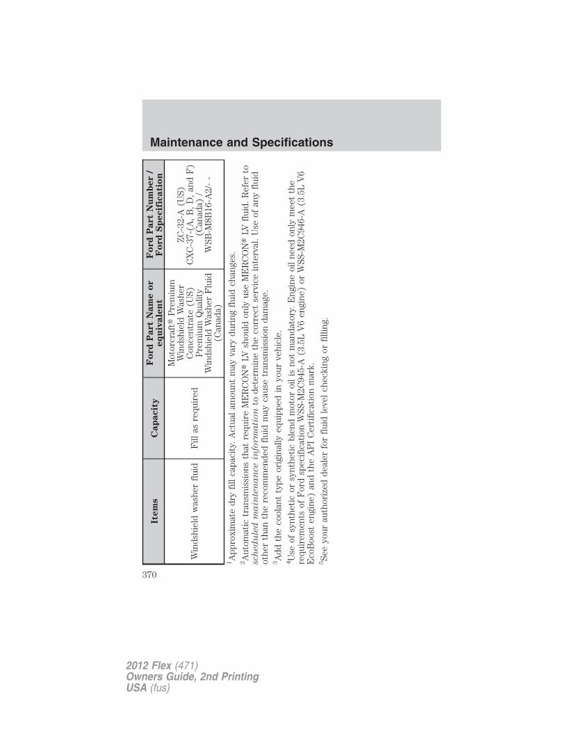
Item
sC
ap
acit
yF
ord
Part
Nam
eo
req
uiv
ale
nt
Fo
rd
Part
Nu
mb
er
/F
ord
Sp
ecif
icati
on
Win
dshi
eld
was
her
flui
dF
illas
requ
ired
Mot
orcr
aft�
Pre
miu
mW
inds
hiel
dW
ashe
rC
once
ntra
te(U
S)P
rem
ium
Qua
lity
Win
dshi
eld
Was
her
Flu
id(C
anad
a)
ZC
-32-
A(U
S)C
XC
-37-
(A,
B,
D,
and
F)
(Can
ada)
/W
SB-M
8B16
-A2/
--
1A
ppro
xim
ate
dry
fill
capa
city
.A
ctua
lam
ount
may
vary
duri
ngfl
uid
chan
ges.
2A
utom
atic
tran
smis
sion
sth
atre
quir
eM
ER
CO
N�
LVsh
ould
only
use
ME
RC
ON
�LV
flui
d.R
efer
tosch
ed
ule
dm
ain
ten
an
ce
info
rm
ati
on
tode
term
ine
the
corr
ect
serv
ice
inte
rval
.U
seof
any
flui
dot
her
than
the
reco
mm
ende
dfl
uid
may
caus
etr
ansm
issi
onda
mag
e.3A
ddth
eco
olan
tty
peor
igin
ally
equi
pped
inyo
urve
hicl
e.4U
seof
synt
heti
cor
synt
heti
cbl
end
mot
oroi
lis
not
man
dato
ry.
Eng
ine
oil
need
only
mee
tth
ere
quir
emen
tsof
For
dsp
ecif
icat
ion
WSS
-M2C
945-
A(3
.5L
V6
engi
ne)
orW
SS-M
2C94
6-A
(3.5
LV
6E
coB
oost
engi
ne)
and
the
AP
IC
erti
fica
tion
mar
k.5Se
eyo
urau
thor
ized
deal
erfo
rfl
uid
leve
lch
ecki
ngor
filli
ng.
Maintenance and Specifications
370
2012 Flex (471)Owners Guide, 2nd PrintingUSA (fus)
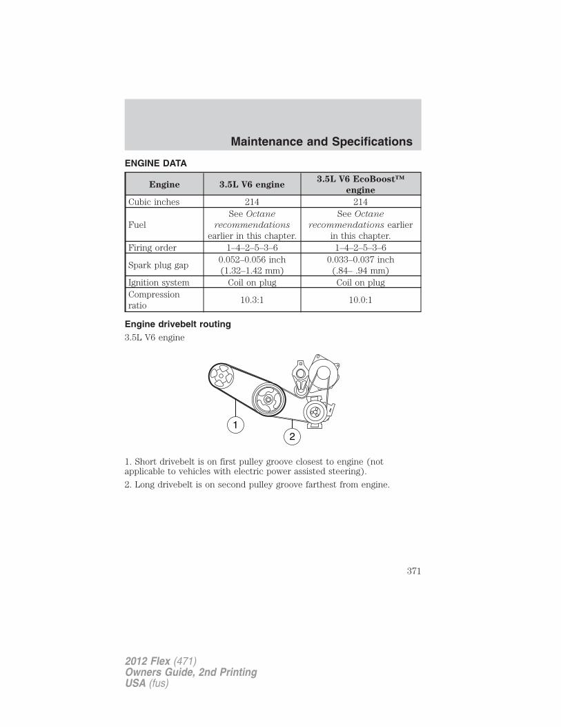
ENGINE DATA
Engine 3.5L V6 engine3.5L V6 EcoBoost™
engine
Cubic inches 214 214
FuelSee Octane
recommendations
earlier in this chapter.
See Octane
recommendations earlierin this chapter.
Firing order 1–4–2–5–3–6 1–4–2–5–3–6
Spark plug gap0.052–0.056 inch(1.32–1.42 mm)
0.033–0.037 inch(.84– .94 mm)
Ignition system Coil on plug Coil on plugCompressionratio
10.3:1 10.0:1
Engine drivebelt routing3.5L V6 engine
1. Short drivebelt is on first pulley groove closest to engine (notapplicable to vehicles with electric power assisted steering).
2. Long drivebelt is on second pulley groove farthest from engine.
Maintenance and Specifications
371
2012 Flex (471)Owners Guide, 2nd PrintingUSA (fus)
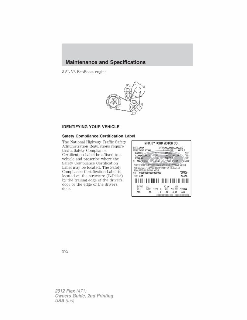
3.5L V6 EcoBoost engine
IDENTIFYING YOUR VEHICLE
Safety Compliance Certification LabelThe National Highway Traffic SafetyAdministration Regulations requirethat a Safety ComplianceCertification Label be affixed to avehicle and prescribe where theSafety Compliance CertificationLabel may be located. The SafetyCompliance Certification Label islocated on the structure (B-Pillar)by the trailing edge of the driver’sdoor or the edge of the driver’sdoor.
Maintenance and Specifications
372
2012 Flex (471)Owners Guide, 2nd PrintingUSA (fus)
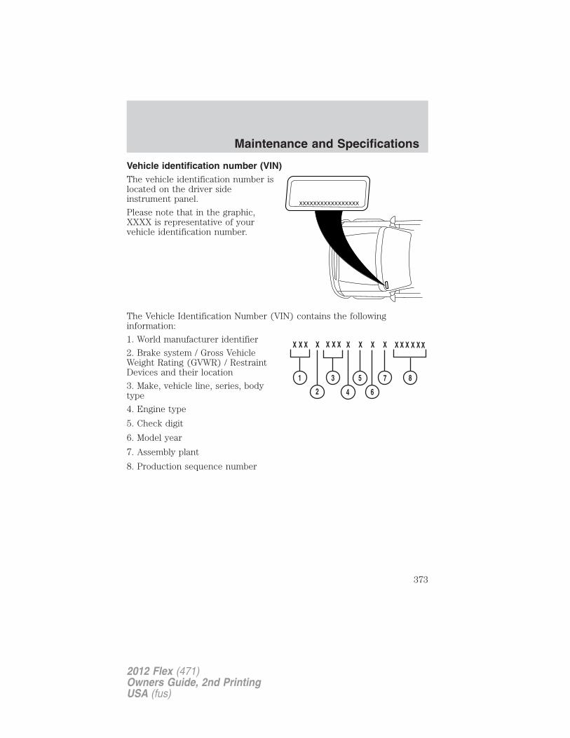
Vehicle identification number (VIN)The vehicle identification number islocated on the driver sideinstrument panel.
Please note that in the graphic,XXXX is representative of yourvehicle identification number.
The Vehicle Identification Number (VIN) contains the followinginformation:
1. World manufacturer identifier
2. Brake system / Gross VehicleWeight Rating (GVWR) / RestraintDevices and their location
3. Make, vehicle line, series, bodytype
4. Engine type
5. Check digit
6. Model year
7. Assembly plant
8. Production sequence number
XXXXXXXXXXXXXXXXX
Maintenance and Specifications
373
2012 Flex (471)Owners Guide, 2nd PrintingUSA (fus)
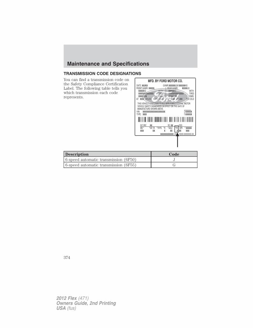
TRANSMISSION CODE DESIGNATIONSYou can find a transmission code onthe Safety Compliance CertificationLabel. The following table tells youwhich transmission each coderepresents.
Description Code
6-speed automatic transmission (6F50) J6-speed automatic transmission (6F55) G
Maintenance and Specifications
374
2012 Flex (471)Owners Guide, 2nd PrintingUSA (fus)

FORD CUSTOM ACCESSORIES FOR YOUR VEHICLEA wide selection of Ford Custom Accessories are available for yourvehicle through your local Ford or Ford of Canada dealer. These qualityaccessories have been specifically engineered to fulfill your automotiveneeds; they are custom designed to complement the style andaerodynamic appearance of your vehicle. In addition, each accessory ismade from high quality materials and meets or exceeds Ford’s rigorousengineering and safety specifications. Ford Motor Company will repair orreplace any properly dealer-installed Ford Custom Accessories found tobe defective in factory-supplied materials or workmanship during thewarranty period, as well as any component damaged by the defectiveaccessories. The accessories will be warranted for whichever providesyou the greatest benefit:
• 12 months or 12,000 miles (20,000 km) (whichever occurs first), or
• the remainder of your new vehicle limited warranty.
Contact your dealer for details and a copy of the warranty.
The following is a list of several Ford Custom Accessories. Not allaccessories are available for all models. For a complete listing of theaccessories that are available for your vehicle, please contact your dealeror visit our online store at: www.fordaccessories.com (U.S. only).
Exterior style
•Bug shield •Splash guards•Deflectors •Applique’ trim kit*•Graphic kits •Chrome wheels•Spoiler
Interior style
•Ambient lighting •Sport pedals•Backlit door sill plates •Interior trim kit*•Floor mats •Rear seat entertainment*
Accessories
375
2012 Flex (471)Owners Guide, 2nd PrintingUSA (fus)
Lifestyle
•Ash cup / coin holder •Roof racks and carriers*•Navigation* •Cargo net•SUV camping net* •Conversation mirror•Trailer hitches, wiring harnesses and accessories•Cargo organization and management
Peace of mind
•Remote start •Wheel locks•Vehicle security•Vehicle tracking and recovery*•Bumper and hitch mounted parking sensors*•Locking fuel plug for capless fuel systems
*Ford Licensed Accessories (FLA) are warranted by the accessorymanufacturer’s warranty. Ford Licensed Accessories are fully designedand developed by the accessory manufacturer and have not beendesigned or tested to Ford Motor Company engineering requirements.Contact your Ford dealer for details regarding the manufacturer’s limitedwarranty and/or a copy of the FLA product limited warranty offered bythe accessory manufacturer.
For maximum vehicle performance, keep the following information inmind when adding accessories or equipment to your vehicle:
• When adding accessories, equipment, passengers and luggage to yourvehicle, do not exceed the total weight capacity of the vehicle or ofthe front or rear axle (GVWR or GAWR as indicated on the SafetyCompliance Certification label). Consult your authorized dealer forspecific weight information.
• The Federal Communications Commission (FCC) and Canadian RadioTelecommunications Commission (CRTC) regulate the use of mobilecommunications systems — such as two-way radios, telephones andtheft alarms - that are equipped with radio transmitters. Any suchequipment installed in your vehicle should comply with FCC or CRTCregulations and should be installed only by a qualified servicetechnician.
Accessories
376
2012 Flex (471)Owners Guide, 2nd PrintingUSA (fus)
• Mobile communications systems may harm the operation of yourvehicle, particularly if they are not properly designed for automotiveuse.
• To avoid interference with other vehicle functions, such as anti-lockbraking systems, amateur radio users who install radios and antennasonto their vehicle should not locate the amateur radio antennas in thearea of the driver’s side hood.
• Any non-Ford custom electrical or electronic accessories orcomponents that are added to the vehicle by the authorized dealer orthe owner, may adversely affect battery performance and durability,and may also adversely affect the performance of other electricalsystems in the vehicle.
Accessories
377
2012 Flex (471)Owners Guide, 2nd PrintingUSA (fus)
FORD ESP EXTENDED SERVICE PLANS (U.S. ONLY)More than 32 million Ford and Lincoln owners have discovered thepowerful protection of Ford ESP. It is the only extended service planbacked by Ford Motor Company, and provides “peace of mind”protection beyond the New Vehicle Limited Warranty coverage.Up to 500+ Covered Vehicle Components
There are four, new-vehicle Extended Service Plans with different levelsof coverage. Ask your dealer for details.PremiumCare – Our most comprehensive coverage. With over 500covered components, this plan is so complete that we generally onlydiscuss what’s not covered!ExtraCare – Covers 113 components, and includes many high-techitems.BaseCare – Covers 84 components.PowertrainCare – Covers 29 critical components.Ford ESP is honored by all Ford and Lincoln Dealers in the U.S.and Canada It’s the only extended service plan authorized and backedby Ford Motor Company. That means you get:
• Reliable, quality service anywhere you go.
• Factory-trained technicians.
• Ford Authorized Parts used with every covered repair.
Rental car reimbursement
If your vehicle is kept overnight for covered repairs, you areeligible for rental car coverage, including Bumper-to-Bumper warrantyrepairs, or manufacturer’s recalls.
Transferable coverage
If you sell your vehicle before your Ford ESP coverage expires, you cantransfer any remaining coverage to the new owner. Whenever you’reready to sell your car, prospective buyers may feel better about taking arisk on your used vehicle. Ford ESP may add resale value!
Plus, exclusive 24/7 roadside assistance, including:
• Towing, flat-tire change and battery jump starts.
• Out-of-fuel and lock-out assistance.
• Travel expense reimbursement for lodging, meals and rental car.
• Destination assistance for taxi, shuttle, rental car coverage andemergency transportation.
Ford Extended Service Plan
378
2012 Flex (471)Owners Guide, 2nd PrintingUSA (fus)
Ford ESP Can Quickly Pay for Itself
One service bill – the cost of parts and labor – can easily exceed theprice of your Ford ESP Service Contract. With Ford ESP, you minimizeyour risk for unexpected repair bills and rising repair costs.
Avoid the rising cost of properly maintaining your vehicle!
Ford ESP also offers a Premium Maintenance Plan that covers items thatroutinely wear out.
The coverage is prepaid, so you never have to worry about affordingyour vehicle maintenance. It covers regular checkups, routineinspections, preventive care and replacement of items that requireperiodic attention for normal “wear”:
• Wiper blades • Brake pads and linings
• Spark plugs (except California) • Shock absorbers
• Clutch disc • Belts and hoses
Contact your selling Ford or Lincoln dealership today so they cancustomize a Ford Extended Service Plan that fits your driving lifestyleand budget.
Interest free finance options available
Take advantage of our installment payment plan, just a 10% downpayment will provide you with an affordable no interest, no-fee paymentopportunity.
Ford Extended Service Plan
379
2012 Flex (471)Owners Guide, 2nd PrintingUSA (fus)
Ford Extended Service Plan
380
2012 Flex (471)Owners Guide, 2nd PrintingUSA (fus)
FORD ESP EXTENDED SERVICE PLANS (CANADA ONLY)You can get more protection for your vehicle by purchasing a FordExtended Service Plan (ESP). Ford ESP is the only service contractbacked by Ford Motor Company of Canada, Limited. Depending on theplan you purchase, Ford ESP provides benefits such as:
• Rental reimbursement
• Coverage for certain maintenance and wear items
• Protection against repair costs after your New Vehicle LimitedWarranty Coverage expires
• Roadside Assistance benefits
There are several Ford ESP plans available in various time, distance anddeductible combinations. Each plan is tailored to fit your own drivingneeds, including reimbursement for towing and rental.
When you purchase Ford ESP, you receive added peace-of-mindprotection throughout Canada and the United States, provided by anetwork of participating Ford Motor Company dealers.
For more information, visit your local Ford of Canada dealer orwww.ford.ca to find the Ford Extended Service Plan that is right for you.
Note: Repairs performed outside of Canada and the United States arenot eligible for Ford ESP coverage.
Ford Extended Service Plan
381
2012 Flex (471)Owners Guide, 2nd PrintingUSA (fus)
GENERAL MAINTENANCE INFORMATION
Why maintain your vehicle?Carefully following this schedule helps protect against major repairexpenses resulting from neglect or inadequate maintenance and may alsohelp to increase the value of your vehicle when you sell or trade it.
It is your responsibility to see that all scheduled maintenance isperformed and that the materials used meet Ford engineeringspecifications as identified in the Maintenance and Specificationschapter. Failure to perform scheduled maintenance specific in this guidewill invalidate warranty coverage on parts affected by the lack ofmaintenance. Be sure receipts for completed maintenance are kept withthe vehicle and confirmation of the work performed is always recorded inthis guide.
Your dealer has factory-trained technicians who can perform the requiredmaintenance using genuine Ford parts. They are committed to meetingyour service needs and to assuring your continuing satisfaction.
Protecting your investmentMaintenance is an investment that will pay dividends in the form ofimproved reliability, durability and resale value. To ensure the properperformance of your vehicle and its emission control systems, it isimperative that scheduled maintenance be completed at the designatedintervals.
Your vehicle is equipped with the Intelligent Oil Life Monitor™ (IOLM)system which displays a message in the message center at the proper oilchange service interval; this interval may be up to one year or10,000 miles (16,000 km). When ENGINE OIL CHANGE DUE or OILCHANGE REQUIRED appears in the message center display, it’s time foran oil change; the oil change must be done within two weeks or500 miles (800 km) of the ENGINE OIL CHANGE DUE or OIL CHANGEREQUIRED message appearing. The Intelligent Oil Life Monitor™ mustbe reset after each oil change; refer to the Instrument Cluster chapter.
If your message center is prematurely reset or becomes inoperative, youshould perform the oil change interval at six months or 5,000 miles(8,000 km) from your last oil change.
Scheduled Maintenance
382
2012 Flex (471)Owners Guide, 2nd PrintingUSA (fus)
Your vehicle is very sophisticated and built with multiple complexperformance systems. Every manufacturer develops these systems usingdifferent specifications and performance features. That’s why it’simportant to rely upon your dealership to properly diagnose and repairyour vehicle.
Ford Motor Company has recommended maintenance intervals forvarious parts and component systems based upon engineering testing.Ford Motor Company relies upon this testing to determine the mostappropriate mileage for replacement of oils and fluids to protect yourvehicle at the lowest overall cost to you and recommends againstmaintenance schedules that deviate from the scheduled maintenanceinformation.
Ford strongly recommends the use of genuine Ford replacement parts.Parts other than Ford, Motorcraft� or Ford-authorized remanufacturedparts that are used for maintenance replacement or for the service ofcomponents affecting emission control must be equivalent to genuineFord Motor Company parts in performance and durability. It is theowner’s responsibility to determine the equivalency of such parts. Pleaseconsult your Warranty Guide for complete warranty information.
Chemicals or additives not approved by Ford are not required for factoryrecommended maintenance. In fact, Ford Motor Company recommendsagainst the use of such additive products unless specificallyrecommended by Ford for a particular application.
Oils, fluids and flushingIn many cases, fluid discoloration is a normal operating characteristicand, by itself, does not necessarily indicate a concern or that the fluidneeds to be changed. However, discolored fluids that also show signs ofoverheating and/or foreign material contamination should be inspectedimmediately by a qualified expert such as the factory-trained techniciansat your dealership. Your vehicle’s oils and fluids should be changed at thespecified intervals or in conjunction with a repair. Flushing is a viableway to change fluid for many vehicle sub-systems during scheduledmaintenance. It is critical that systems are flushed only with new fluidthat is the same as that required to fill and operate the system, or usinga Ford-approved flushing chemical.
Scheduled Maintenance
383
2012 Flex (471)Owners Guide, 2nd PrintingUSA (fus)
Genuine Ford parts and serviceWhen planning your maintenance services, consider your dealership forall your vehicle’s needs.
There are a lot of reasons why visiting your dealership for all yourservice needs is a great way to help keep your vehicle running great.
ConvenienceMany dealerships have extended evening and Saturday hours to makeyour service visit more convenient. How’s that for quality service?
Factory-trained techniciansService technicians participate in extensive factory-sponsoredcertification training to help them become experts on the operation ofyour vehicle. Ask your dealership about the training and certificationtheir technicians have received.
Genuine Ford and Motorcraft� replacement partsDealerships stock Ford and Motorcraft� branded replacement parts.These parts meet or exceed Ford Motor Company’s specifications, andwe stand behind them. Parts installed at your dealership carry anationwide, 12 month/12,000 mile (20,000 km) parts and labor limitedwarranty. Your dealer can give you details.
Value shopping for your vehicle’s maintenance needsYour dealership recognizes the competitive landscape of maintenance andlight repair automotive services. With factory-trained technicians, andone-stop service from routine maintenance like oil changes and tirerotations to repairs like brake service, check out the value your dealerscan offer.
Owner Checks and ServicesCertain basic maintenance checks and inspections should be performedby the owner or a service technician at the intervals indicated. Serviceinformation and supporting specifications are provided in this owner’sguide.
Scheduled Maintenance
384
2012 Flex (471)Owners Guide, 2nd PrintingUSA (fus)
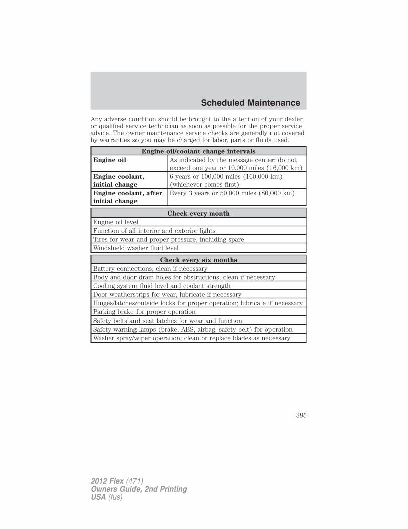
Any adverse condition should be brought to the attention of your dealeror qualified service technician as soon as possible for the proper serviceadvice. The owner maintenance service checks are generally not coveredby warranties so you may be charged for labor, parts or fluids used.
Engine oil/coolant change intervals
Engine oil As indicated by the message center: do notexceed one year or 10,000 miles (16,000 km)
Engine coolant,
initial change
6 years or 100,000 miles (160,000 km)(whichever comes first)
Engine coolant, after
initial change
Every 3 years or 50,000 miles (80,000 km)
Check every month
Engine oil levelFunction of all interior and exterior lightsTires for wear and proper pressure, including spareWindshield washer fluid level
Check every six months
Battery connections; clean if necessaryBody and door drain holes for obstructions; clean if necessaryCooling system fluid level and coolant strengthDoor weatherstrips for wear; lubricate if necessaryHinges/latches/outside locks for proper operation; lubricate if necessaryParking brake for proper operationSafety belts and seat latches for wear and functionSafety warning lamps (brake, ABS, airbag, safety belt) for operationWasher spray/wiper operation; clean or replace blades as necessary
Scheduled Maintenance
385
2012 Flex (471)Owners Guide, 2nd PrintingUSA (fus)
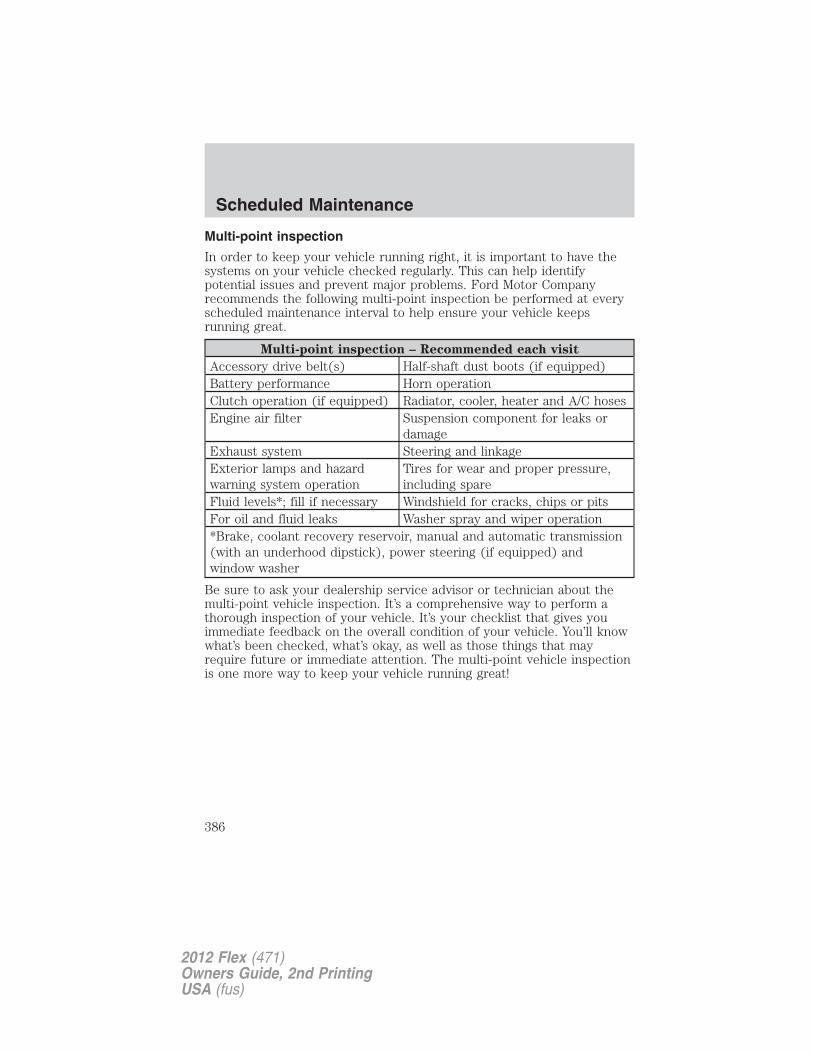
Multi-point inspection
In order to keep your vehicle running right, it is important to have thesystems on your vehicle checked regularly. This can help identifypotential issues and prevent major problems. Ford Motor Companyrecommends the following multi-point inspection be performed at everyscheduled maintenance interval to help ensure your vehicle keepsrunning great.
Multi-point inspection – Recommended each visit
Accessory drive belt(s) Half-shaft dust boots (if equipped)Battery performance Horn operationClutch operation (if equipped) Radiator, cooler, heater and A/C hosesEngine air filter Suspension component for leaks or
damageExhaust system Steering and linkageExterior lamps and hazardwarning system operation
Tires for wear and proper pressure,including spare
Fluid levels*; fill if necessary Windshield for cracks, chips or pitsFor oil and fluid leaks Washer spray and wiper operation*Brake, coolant recovery reservoir, manual and automatic transmission(with an underhood dipstick), power steering (if equipped) andwindow washer
Be sure to ask your dealership service advisor or technician about themulti-point vehicle inspection. It’s a comprehensive way to perform athorough inspection of your vehicle. It’s your checklist that gives youimmediate feedback on the overall condition of your vehicle. You’ll knowwhat’s been checked, what’s okay, as well as those things that mayrequire future or immediate attention. The multi-point vehicle inspectionis one more way to keep your vehicle running great!
Scheduled Maintenance
386
2012 Flex (471)Owners Guide, 2nd PrintingUSA (fus)
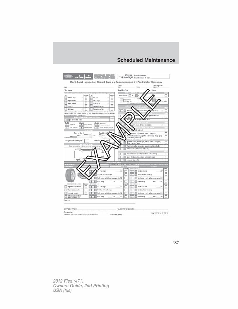
Scheduled Maintenance
387
2012 Flex (471)Owners Guide, 2nd PrintingUSA (fus)
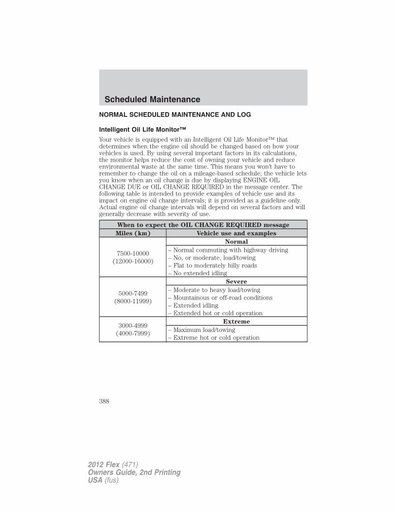
NORMAL SCHEDULED MAINTENANCE AND LOG
Intelligent Oil Life Monitor™
Your vehicle is equipped with an Intelligent Oil Life Monitor™ thatdetermines when the engine oil should be changed based on how yourvehicles is used. By using several important factors in its calculations,the monitor helps reduce the cost of owning your vehicle and reduceenvironmental waste at the same time. This means you won’t have toremember to change the oil on a mileage-based schedule; the vehicle letsyou know when an oil change is due by displaying ENGINE OILCHANGE DUE or OIL CHANGE REQUIRED in the message center. Thefollowing table is intended to provide examples of vehicle use and itsimpact on engine oil change intervals; it is provided as a guideline only.Actual engine oil change intervals will depend on several factors and willgenerally decrease with severity of use.
When to expect the OIL CHANGE REQUIRED message
Miles (km) Vehicle use and examples
7500-10000(12000-16000)
Normal
– Normal commuting with highway driving– No, or moderate, load/towing– Flat to moderately hilly roads– No extended idling
5000-7499(8000-11999)
Severe
– Moderate to heavy load/towing– Mountainous or off-road conditions– Extended idling– Extended hot or cold operation
3000-4999(4000-7999)
Extreme
– Maximum load/towing– Extreme hot or cold operation
Scheduled Maintenance
388
2012 Flex (471)Owners Guide, 2nd PrintingUSA (fus)
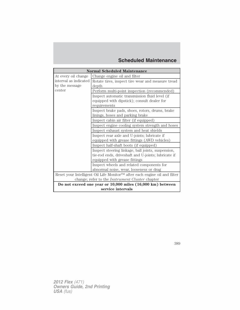
Normal Scheduled Maintenance
At every oil changeinterval as indicatedby the messagecenter
Change engine oil and filterRotate tires, inspect tire wear and measure treaddepthPerform multi-point inspection (recommended)Inspect automatic transmission fluid level (ifequipped with dipstick); consult dealer forrequirementsInspect brake pads, shoes, rotors, drums, brakelinings, hoses and parking brakeInspect cabin air filter (if equipped)Inspect engine cooling system strength and hosesInspect exhaust system and heat shieldsInspect rear axle and U-joints; lubricate ifequipped with grease fittings (AWD vehicles)Inspect half-shaft boots (if equipped)Inspect steering linkage, ball joints, suspension,tie-rod ends, driveshaft and U-joints; lubricate ifequipped with grease fittingsInspect wheels and related components forabnormal noise, wear, looseness or drag
Reset your Intelligent Oil Life Monitor™ after each engine oil and filterchange; refer to the Instrument Cluster chapter
Do not exceed one year or 10,000 miles (16,000 km) between
service intervals
Scheduled Maintenance
389
2012 Flex (471)Owners Guide, 2nd PrintingUSA (fus)
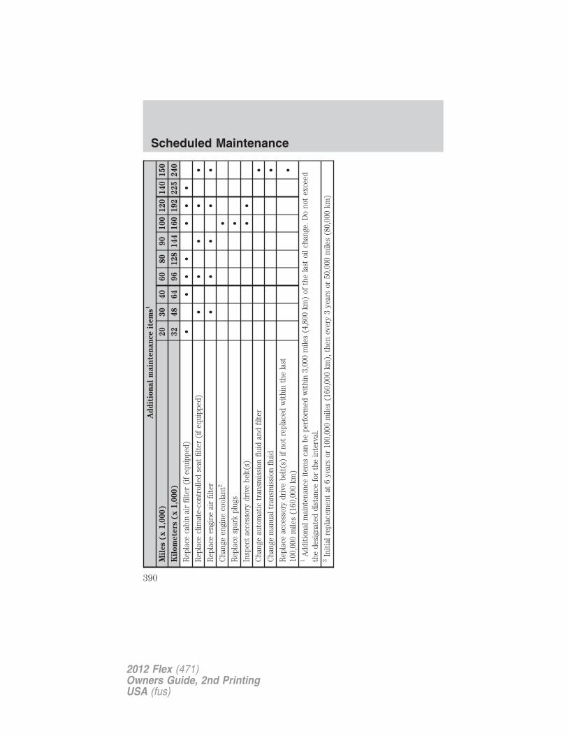
Ad
dit
ion
al
main
ten
an
ce
item
s1
Mil
es
(x
1,0
00)
20
30
40
60
80
90
100
120
140
150
Kil
om
ete
rs(x
1,0
00)
32
48
64
96
128
144
160
192
225
240
Rep
lace
cabi
nai
rfil
ter
(if
equi
pped
)•
••
••
••
Rep
lace
clim
ate-
cont
rolle
dse
atfil
ter
(if
equi
pped
)•
••
••
Rep
lace
engi
neai
rfil
ter
••
••
•C
hang
een
gine
cool
ant2
•R
epla
cesp
ark
plug
s•
Insp
ect
acce
ssor
ydr
ive
belt(
s)•
•C
hang
eau
tom
atic
tran
smis
sion
fluid
and
filte
r•
Cha
nge
man
ualt
rans
mis
sion
fluid
•R
epla
ceac
cess
ory
driv
ebe
lt(s)
ifno
tre
plac
edw
ithin
the
last
100,
000
mile
s(1
60,0
00km
)•
1A
dditi
onal
mai
nten
ance
item
sca
nbe
perf
orm
edw
ithin
3,00
0m
iles
(4,8
00km
)of
the
last
oilc
hang
e.D
ono
tex
ceed
the
desi
gnat
eddi
stan
cefo
rth
ein
terv
al.
2In
itial
repl
acem
ent
at6
year
sor
100,
000
mile
s(1
60,0
00km
),th
enev
ery
3ye
ars
or50
,000
mile
s(8
0,00
0km
)
Scheduled Maintenance
390
2012 Flex (471)Owners Guide, 2nd PrintingUSA (fus)
Maintenance schedule logDEALER VALIDATION:
P&A CODE:RO#: HOURS:DATE: MILEAGE:
DEALER VALIDATION:
P&A CODE:RO#: HOURS:DATE: MILEAGE:
DEALER VALIDATION:
P&A CODE:RO#: HOURS:DATE: MILEAGE:
DEALER VALIDATION:
P&A CODE:RO#: HOURS:DATE: MILEAGE:
DEALER VALIDATION:
P&A CODE:RO#: HOURS:DATE: MILEAGE:
DEALER VALIDATION:
P&A CODE:RO#: HOURS:DATE: MILEAGE:
DEALER VALIDATION:
P&A CODE:RO#: HOURS:DATE: MILEAGE:
DEALER VALIDATION:
P&A CODE:RO#: HOURS:DATE: MILEAGE:
DEALER VALIDATION:
P&A CODE:RO#: HOURS:DATE: MILEAGE:
DEALER VALIDATION:
P&A CODE:RO#: HOURS:DATE: MILEAGE:
Scheduled Maintenance
391
2012 Flex (471)Owners Guide, 2nd PrintingUSA (fus)
DEALER VALIDATION:
P&A CODE:RO#: HOURS:DATE: MILEAGE:
DEALER VALIDATION:
P&A CODE:RO#: HOURS:DATE: MILEAGE:
DEALER VALIDATION:
P&A CODE:RO#: HOURS:DATE: MILEAGE:
DEALER VALIDATION:
P&A CODE:RO#: HOURS:DATE: MILEAGE:
DEALER VALIDATION:
P&A CODE:RO#: HOURS:DATE: MILEAGE:
DEALER VALIDATION:
P&A CODE:RO#: HOURS:DATE: MILEAGE:
DEALER VALIDATION:
P&A CODE:RO#: HOURS:DATE: MILEAGE:
DEALER VALIDATION:
P&A CODE:RO#: HOURS:DATE: MILEAGE:
DEALER VALIDATION:
P&A CODE:RO#: HOURS:DATE: MILEAGE:
DEALER VALIDATION:
P&A CODE:RO#: HOURS:DATE: MILEAGE:
Scheduled Maintenance
392
2012 Flex (471)Owners Guide, 2nd PrintingUSA (fus)

DEALER VALIDATION:
P&A CODE:RO#: HOURS:DATE: MILEAGE:
DEALER VALIDATION:
P&A CODE:RO#: HOURS:DATE: MILEAGE:
DEALER VALIDATION:
P&A CODE:RO#: HOURS:DATE: MILEAGE:
DEALER VALIDATION:
P&A CODE:RO#: HOURS:DATE: MILEAGE:
DEALER VALIDATION:
P&A CODE:RO#: HOURS:DATE: MILEAGE:
DEALER VALIDATION:
P&A CODE:RO#: HOURS:DATE: MILEAGE:
DEALER VALIDATION:
P&A CODE:RO#: HOURS:DATE: MILEAGE:
DEALER VALIDATION:
P&A CODE:RO#: HOURS:DATE: MILEAGE:
DEALER VALIDATION:
P&A CODE:RO#: HOURS:DATE: MILEAGE:
DEALER VALIDATION:
P&A CODE:RO#: HOURS:DATE: MILEAGE:
Scheduled Maintenance
393
2012 Flex (471)Owners Guide, 2nd PrintingUSA (fus)
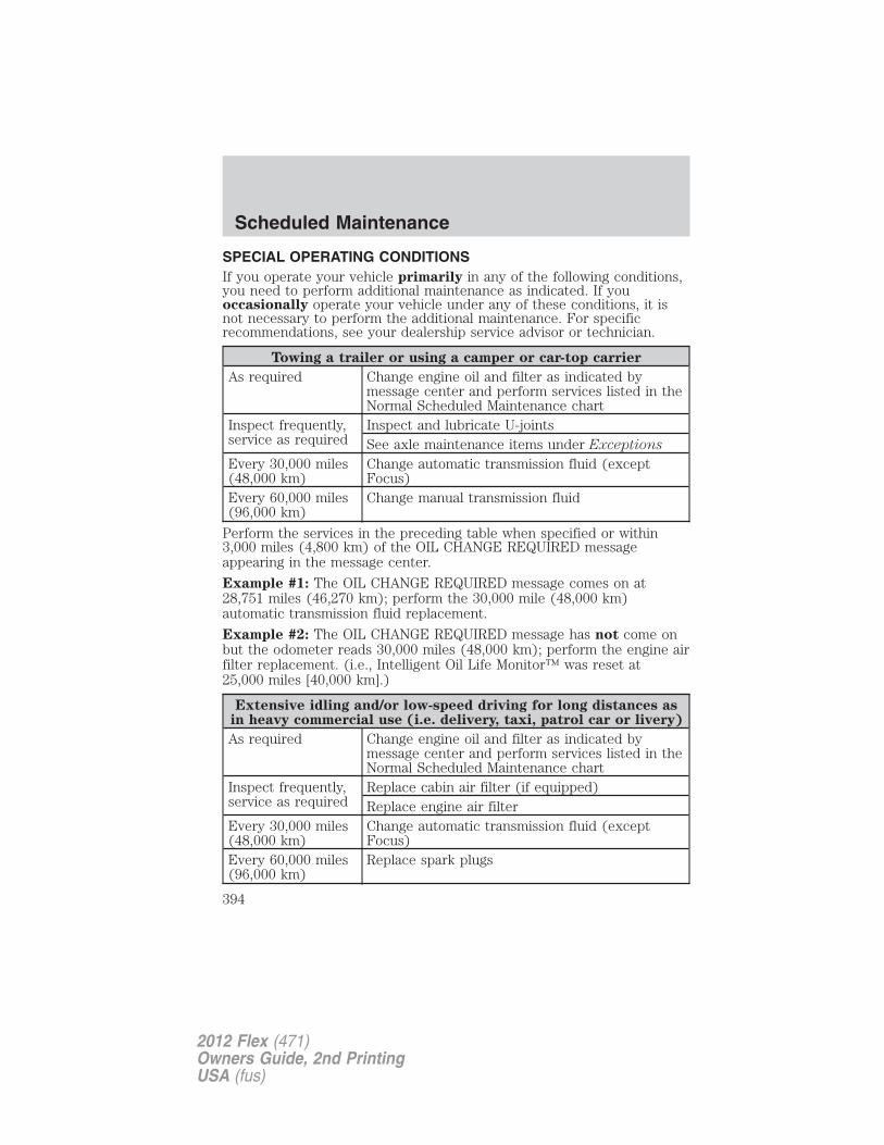
SPECIAL OPERATING CONDITIONSIf you operate your vehicle primarily in any of the following conditions,you need to perform additional maintenance as indicated. If youoccasionally operate your vehicle under any of these conditions, it isnot necessary to perform the additional maintenance. For specificrecommendations, see your dealership service advisor or technician.
Towing a trailer or using a camper or car-top carrier
As required Change engine oil and filter as indicated bymessage center and perform services listed in theNormal Scheduled Maintenance chart
Inspect frequently,service as required
Inspect and lubricate U-jointsSee axle maintenance items under Exceptions
Every 30,000 miles(48,000 km)
Change automatic transmission fluid (exceptFocus)
Every 60,000 miles(96,000 km)
Change manual transmission fluid
Perform the services in the preceding table when specified or within3,000 miles (4,800 km) of the OIL CHANGE REQUIRED messageappearing in the message center.
Example #1: The OIL CHANGE REQUIRED message comes on at28,751 miles (46,270 km); perform the 30,000 mile (48,000 km)automatic transmission fluid replacement.
Example #2: The OIL CHANGE REQUIRED message has not come onbut the odometer reads 30,000 miles (48,000 km); perform the engine airfilter replacement. (i.e., Intelligent Oil Life Monitor™ was reset at25,000 miles [40,000 km].)
Extensive idling and/or low-speed driving for long distances asin heavy commercial use (i.e. delivery, taxi, patrol car or livery)
As required Change engine oil and filter as indicated bymessage center and perform services listed in theNormal Scheduled Maintenance chart
Inspect frequently,service as required
Replace cabin air filter (if equipped)Replace engine air filter
Every 30,000 miles(48,000 km)
Change automatic transmission fluid (exceptFocus)
Every 60,000 miles(96,000 km)
Replace spark plugs
Scheduled Maintenance
394
2012 Flex (471)Owners Guide, 2nd PrintingUSA (fus)
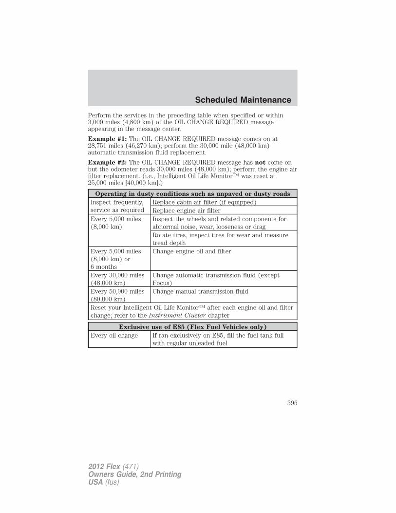
Perform the services in the preceding table when specified or within3,000 miles (4,800 km) of the OIL CHANGE REQUIRED messageappearing in the message center.
Example #1: The OIL CHANGE REQUIRED message comes on at28,751 miles (46,270 km); perform the 30,000 mile (48,000 km)automatic transmission fluid replacement.
Example #2: The OIL CHANGE REQUIRED message has not come onbut the odometer reads 30,000 miles (48,000 km); perform the engine airfilter replacement. (i.e., Intelligent Oil Life Monitor™ was reset at25,000 miles [40,000 km].)
Operating in dusty conditions such as unpaved or dusty roads
Inspect frequently,service as required
Replace cabin air filter (if equipped)Replace engine air filter
Every 5,000 miles(8,000 km)
Inspect the wheels and related components forabnormal noise, wear, looseness or dragRotate tires, inspect tires for wear and measuretread depth
Every 5,000 miles(8,000 km) or6 months
Change engine oil and filter
Every 30,000 miles(48,000 km)
Change automatic transmission fluid (exceptFocus)
Every 50,000 miles(80,000 km)
Change manual transmission fluid
Reset your Intelligent Oil Life Monitor™ after each engine oil and filterchange; refer to the Instrument Cluster chapter
Exclusive use of E85 (Flex Fuel Vehicles only)
Every oil change If ran exclusively on E85, fill the fuel tank fullwith regular unleaded fuel
Scheduled Maintenance
395
2012 Flex (471)Owners Guide, 2nd PrintingUSA (fus)
Special operating condition logDEALER VALIDATION:
P&A CODE:RO#: HOURS:DATE: MILEAGE:
DEALER VALIDATION:
P&A CODE:RO#: HOURS:DATE: MILEAGE:
DEALER VALIDATION:
P&A CODE:RO#: HOURS:DATE: MILEAGE:
DEALER VALIDATION:
P&A CODE:RO#: HOURS:DATE: MILEAGE:
DEALER VALIDATION:
P&A CODE:RO#: HOURS:DATE: MILEAGE:
DEALER VALIDATION:
P&A CODE:RO#: HOURS:DATE: MILEAGE:
DEALER VALIDATION:
P&A CODE:RO#: HOURS:DATE: MILEAGE:
DEALER VALIDATION:
P&A CODE:RO#: HOURS:DATE: MILEAGE:
DEALER VALIDATION:
P&A CODE:RO#: HOURS:DATE: MILEAGE:
DEALER VALIDATION:
P&A CODE:RO#: HOURS:DATE: MILEAGE:
Scheduled Maintenance
396
2012 Flex (471)Owners Guide, 2nd PrintingUSA (fus)
DEALER VALIDATION:
P&A CODE:RO#: HOURS:DATE: MILEAGE:
DEALER VALIDATION:
P&A CODE:RO#: HOURS:DATE: MILEAGE:
DEALER VALIDATION:
P&A CODE:RO#: HOURS:DATE: MILEAGE:
DEALER VALIDATION:
P&A CODE:RO#: HOURS:DATE: MILEAGE:
DEALER VALIDATION:
P&A CODE:RO#: HOURS:DATE: MILEAGE:
DEALER VALIDATION:
P&A CODE:RO#: HOURS:DATE: MILEAGE:
DEALER VALIDATION:
P&A CODE:RO#: HOURS:DATE: MILEAGE:
DEALER VALIDATION:
P&A CODE:RO#: HOURS:DATE: MILEAGE:
DEALER VALIDATION:
P&A CODE:RO#: HOURS:DATE: MILEAGE:
DEALER VALIDATION:
P&A CODE:RO#: HOURS:DATE: MILEAGE:
Scheduled Maintenance
397
2012 Flex (471)Owners Guide, 2nd PrintingUSA (fus)
EXCEPTIONSThere are several exceptions to the Normal Schedule. They are listedbelow:
Normal vehicle axle maintenance: Rear axles and power take-off(PTO) units with synthetic fluid and light-duty trucks equipped withFord-design axles are lubricated for life; do not check or change fluidunless a leak is suspected, service is required or the assembly has beensubmerged in water. During long periods of trailer towing with outsidetemperatures above 70°F (21°C) and at wide-open throttle for longperiods above 45 mph (72 km/h), non-synthetic rear axle fluids shouldbe changed every 3,000 miles (4,800 km) or three months, whichevercomes first. This interval can be waived if the axle is filled with 75W140synthetic gear fluid meeting Ford specification WSL-M2C192-A, partnumber F1TZ-19580-B or equivalent. Add friction modifier XL-3(EST-M2C118-A) or equivalent for complete refill of Traction-Lok rearaxles (refer to Maintenance product specifications and capacities inthe Maintenance and Specifications chapter for details).
Police/Taxi/Livery vehicle axle maintenance: Change rear axle fluidevery 100,000 miles (160,000 km). Rear axle fluid change may be waivedif the axle was filled with 75W140 synthetic gear fluid meeting Fordspecification WSL-M2C192-A, part number FITZ-19580-B or equivalent.Add four ounces (118 mL) of additive friction modifier XL-3(EST-M2C118-A) or equivalent for complete refill of Traction-Lok rearaxles. The axle fluid should be changed anytime the axle has beensubmerged in water
California fuel filter replacement: If the vehicle is registered inCalifornia, the California Air Resources Board has determined that thefailure to perform this maintenance item will not nullify the emissionwarranty or limit recall liability prior to the completion of the vehicle’suseful life. Ford Motor Company, however, urges you to have allrecommended maintenance services performed at the specified intervalsand to record all vehicle service.
Class A Motorhome: Change brake fluid every two years.
Hot climate oil change intervals: Vehicles operating in the MiddleEast, North Africa, Sub-Saharan Africa or locations with similar climatesusing an American Petroleum Institute (API) Certified for GasolineEngines (Certification mark) oil or SM or greater, the normal oil changeinterval is 5,000 miles (8,000 km). If using an oil that is less than the APISM (i.e. SL) category, then the oil change service interval is 3,000 mile(4,800 km).
Scheduled Maintenance
398
2012 Flex (471)Owners Guide, 2nd PrintingUSA (fus)
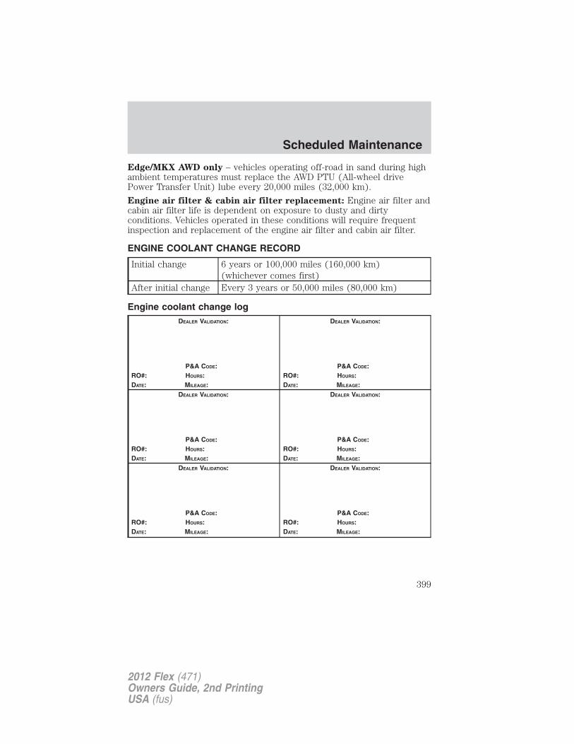
Edge/MKX AWD only – vehicles operating off-road in sand during highambient temperatures must replace the AWD PTU (All-wheel drivePower Transfer Unit) lube every 20,000 miles (32,000 km).
Engine air filter & cabin air filter replacement: Engine air filter andcabin air filter life is dependent on exposure to dusty and dirtyconditions. Vehicles operated in these conditions will require frequentinspection and replacement of the engine air filter and cabin air filter.
ENGINE COOLANT CHANGE RECORD
Initial change 6 years or 100,000 miles (160,000 km)(whichever comes first)
After initial change Every 3 years or 50,000 miles (80,000 km)
Engine coolant change logDEALER VALIDATION:
P&A CODE:RO#: HOURS:DATE: MILEAGE:
DEALER VALIDATION:
P&A CODE:RO#: HOURS:DATE: MILEAGE:
DEALER VALIDATION:
P&A CODE:RO#: HOURS:DATE: MILEAGE:
DEALER VALIDATION:
P&A CODE:RO#: HOURS:DATE: MILEAGE:
DEALER VALIDATION:
P&A CODE:RO#: HOURS:DATE: MILEAGE:
DEALER VALIDATION:
P&A CODE:RO#: HOURS:DATE: MILEAGE:
Scheduled Maintenance
399
2012 Flex (471)Owners Guide, 2nd PrintingUSA (fus)
A
Accessory delay ........................103Active Park Assist .....................275AdvanceTrac ..............................257Airbag supplemental restraintsystem ........................181, 190, 192
and child safety seats ............183description ..............181, 190, 192disposal ....................................195driver airbag ............183, 190, 193indicator light .................189, 195operation .................183, 190, 193passenger airbag .....183, 190, 193side airbag ...............................190
Air cleaner filter ...............363, 366
Air conditioning ..............69, 72, 75manual heating and airconditioning system .................69
All Wheel Drive (AWD),driving off road .........................280
Ambient mood/lighting ...............87
AM/FM .........................................30
Antifreeze (see Enginecoolant) .....................................338
Anti-lock brake system(see Brakes) ..............................255
Anti-theft system ..............139, 142arming the system ..................143disarming a triggeredsystem .....................................144
Audio system (see Radio) .........30
Automatic transmissiondriving an automaticoverdrive .........................266, 268fluid, adding ............................358fluid, checking ........................358fluid, refill capacities ..............367
fluid, specification ..................367Selectshift (SST) ....................270
Auxiliary input jack (Line in) ....39
B
Battery .......................................336acid, treating emergencies .....336jumping a disabled battery ....305maintenance-free ....................336replacement, specifications ...366servicing ..................................336
Belt-Minder� .............................176
Booster seats .............................210
Brakes ........................................254anti-lock ...................................255anti-lock brake system (ABS)warning light ...........................255fluid, checking and adding ....358fluid, refill capacities ..............367fluid, specifications .................367lubricant specifications ..........367parking ....................................256shift interlock ..........................264
Bulbs ............................................87
C
Capacities for refilling fluids ....367
Cargo net ...................................120
CD ................................................30
Cell phone use ............................10
Changing a tire .........................297
Child safety seats ......................200in front seat ............................201in rear seat ..............................201LATCH .....................................204recommendations ...................198tether anchorage hardware ...207
Index
400
2012 Flex (471)Owners Guide, 2nd PrintingUSA (fus)
Child safety seats - boosterseats ...........................................210
Cleaning your vehicleengine compartment ..............319instrument panel ....................322interior .....................................323plastic parts ............................321washing ....................................318waxing .....................................319wheels ......................................319wiper blades ............................321
Climate control (see Airconditioning orHeating) ...........................69, 72, 75
Clock ......................................30, 95
Compass, electronic ....................95calibration .................................97set zone adjustment .................96
Consoleoverhead ....................................94
Controlspower seat ...............................150steering column ......................107
Coolantchecking and adding ..............338refill capacities ................341, 367specifications ..........................367
Cooler ..........................................98
Cruise control(see Speed control) ..................105
Customer Assistance ................287Ford Extended ServicePlan ..................................378, 381Getting assistance outside theU.S. and Canada .....................314Getting roadside assistance ...287Getting the serviceyou need .................................310
Ordering additional owner’sliterature .................................316Utilizing theMediation/ArbitrationProgram ...................................314
D
Daytime running lamps(see Lamps) ................................84Defrost
rear window and rearviewmirrors .......................................75windshield .................................75
Dipstickautomatic transmissionfluid ..........................................358engine oil .................................332
Driving under specialconditions ..........................282, 284
sand .........................................283snow and ice ...........................285through water .................283, 286
DVD region coding .....................65
DVD system .................................48
E
Electronic message center .........20
Emergencies, roadsidejump-starting ..........................305running out of fuel .........304, 350
Emission control system ..........354
Engine ........................................371cleaning ...................................319coolant .....................................338fail-safe cooling .......................344idle speed control ...................336lubrication specifications .......367refill capacities ........................367
Index
401
2012 Flex (471)Owners Guide, 2nd PrintingUSA (fus)
service points ..................328–329Engine block heater .................253Engine oil ..................................332
checking and adding ..............332dipstick ....................................332filter, specifications ................366refill capacities ........................367specifications ..........................367
Event data recording ....................8
Exhaust fumes ..........................252
F
Fail safe cooling ........................344
Family entertainment system ....48
Fleet MyKey programming ......123
Floor mats .........................114–115
Fluid capacities .........................367
Fog lamps ....................................83
Four-Wheel Drive vehiclesdriving off road .......................281
Freezer ........................................98
Fuel ............................................345calculating fueleconomy ............................22, 351cap ...........................................347capacity ...................................367choosing the right fuel ...........348detergent in fuel .....................350filler funnel .............................350filling your vehiclewith fuel ..................345, 347, 351filter, specifications ........345, 366fuel pump shut-off ..................288improving fuel economy ........351octane rating ...................349, 371quality ......................................349running out of fuel .........304, 350
safety information relating toautomotive fuels .....................345
Fuses ..........................................289
G
Garage door opener ..................110
Gas cap (see Fuel cap) ............347
Gas mileage(see Fuel economy) .................351
Gauges .........................................18
H
Hazard flashers .........................288
Headlamps ...................................82aiming ..................................84–85autolamp system .......................82bulb specifications ....................88daytime running lights .............84flash to pass ..............................83high beam .................................83replacing bulbs .........................89turning on and off ....................82
Heatingheating and air conditioningsystem ...........................69, 72, 75
Homelink wireless controlsystem ........................................110
Hood ..........................................327
I
Ignition ...............................249, 371
Illuminated visor mirror .............94
Infant seats(see Safety seats) .....................200
Index
402
2012 Flex (471)Owners Guide, 2nd PrintingUSA (fus)
Inspection/maintenance (I/M)testing ........................................356Instrument panel
cleaning ...................................322cluster ........................................14lighting up panel andinterior .......................................84
J
Jack ............................................297positioning ...............................297storage .....................................297
Jump-starting your vehicle ......305
K
Keyless entry systemautolock ...................................128keypad .....................................137locking and unlockingdoors ........................................138programming entry code .......137
Keys ...................................122, 140positions of the ignition .........249
L
Lampsautolamp system .......................82bulb replacementspecifications chart ..................88daytime running light ...............84fog lamps ...................................83headlamps .................................82headlamps, flash to pass ..........83instrument panel, dimming .....84interior lamps .....................86, 88replacing bulbs .........................89
LATCH anchors .........................204
Liftgate ......................115–116, 134
Lights, warning and indicator ....14anti-lock brakes (ABS) ..........255
Load limits .................................236
Locksautolock ...................................128childproof ................................131doors ........................................128
Lubricant specifications ...........367
Lug nuts ....................................303
Lumbar support, seats .....149, 152
M
Message center ...........................20english/metric button ...............24system check button ................24warning messages .....................24
Mirrors ...............................103–104automatic dimming rearviewmirror ......................................103heated ................................75, 104programmable memory ..........134side view mirrors (power) .....104
Moon roof ..................................109
Motorcraft� parts ..............325, 366
MyKey ........................................123
N
Navigation system .......................68
O
Octane rating ............................349
Oil (see Engine oil) ..................332
Overdrive ...................................265
Index
403
2012 Flex (471)Owners Guide, 2nd PrintingUSA (fus)
P
Parental MyKeyprogramming .............................123Park Assist ................................275Parking brake ............................256Parts(see Motorcraft� parts) ...........366Passenger OccupantClassification Sensor .................168
Power adjustable foot pedals ...105
Power distribution box(see Fuses) ...............................293
Power door locks ......................128
Power liftgate ............................116
Power mirrors ...........................104
Powerpoint ..................................99
Power steering ..........................262fluid, checking and adding ....357fluid, refill capacity ................367fluid, specifications .................367
Power Windows .........................102
R
Radio ............................................306-CD in dash .............................30
Rear heated seats .....................162
Rear seat entertainmentsystem ..........................................48
Rear-view camera system .........273
Recommendations forattaching safety restraints forchildren ......................................198
Refrigerator .................................98
Relays ........................................289
Remote entry system .......131, 133illuminated entry ....................136locking/unlocking doors .........133opening the trunk ...................134panic alarm .............................133replacement/additionaltransmitters .............................136replacing the batteries ...........135
Reverse sensing system ...........271
Roadside assistance ..................287
Roof rack ...................................120
S
Safety belts (see Safetyrestraints) ..........170–172, 174–175
Safety Canopy ...........................192
Safety defects,reporting ............................316–317
Safety restraints ...............170–172,174–175
Belt-Minder� ...........................176extension assembly ................175for adults .................171–172, 174for children .............................195Occupant ClassificationSensor ......................................168warning light andchime ...............................175–176
Safety restraints - LATCHanchors ......................................204
Safety seats for children ..........200
Safety ComplianceCertification Label ....................372
Satellite Radio .............................30
Satellite Radio Information ........44
Index
404
2012 Flex (471)Owners Guide, 2nd PrintingUSA (fus)
Scheduled Maintenance GuideNormal ScheduledMaintenance and Log .............388
Seats ..........................................145child safety seats ....................200climate control ..........................75easy access/easyoutfeature .....................................154front seats ...............................148heated ........................72, 152, 162memory seat ...................134, 153second row seats ............157, 160third row seats ........160, 163–164
Second-row power fold seat ....159
SecuriCode keyless entrysystem ........................................137
SecuriLock passive anti-theftsystem ........................................139
Servicing your vehicle ..............326
Setting the clock .........................30
SOS Post Crash Alert ...............195
Spare tire (see Changingthe Tire) ....................................299
Spark plugs,specifications .....................366, 371
Specification chart,lubricants ...................................367
Speed control ............................105
Starting yourvehicle ........................249–250, 252
jump starting ..........................305
Steering wheelcontrols ....................................107tilting .........................................93
StereoCD-MP3 .....................................30
SYNC� ..........................................68
T
Third-row power fold seat .......164
Tilt steering wheel ......................93
Tire Pressure MonitoringSystem (TPMS)
Tires, Wheels and Loading ....231
Tires ...........................216–217, 297alignment ................................224care ..........................................220changing ..................297, 299–300checking the pressure ............220inflating ...................................218label .........................................230replacing ..................................222rotating ....................................225safety practices .......................224sidewall information ...............226snow tires and chains ............235spare tire .................................297terminology .............................217tire grades ...............................217treadwear ........................216, 221
Towing .......................................243recreational towing .................247Trailer BrakeController-Integrated ..............246trailer towing ..........................243wrecker ....................................308
Trailer BrakeController-Integrated ................246
Transaxlefluid, refill capacities ..............367lubricant specifications ..........367
Transmission .............................265brake-shift interlock (BSI) ....264fluid, checking and adding(automatic) .............................358
Turn signal ..................................86
Index
405
2012 Flex (471)Owners Guide, 2nd PrintingUSA (fus)
U
Universal garage dooropener ........................................110USB port ......................................41
V
Vehicle Identification Number(VIN) ..........................................373Vehicle loading ..........................236Ventilating your vehicle ...........252
W
Warning lights (see Lights) .......14
Washer fluid ..............................330
Water, Driving through .............286
Windowspower .......................................102rear wiper/washer .....................93
Windshield washer fluid andwipers ..........................................92
checking and adding fluid .....330liftgate reservoir .....................331replacing wiper blades ...........331
Wrecker towing .........................308
Index
406
2012 Flex (471)Owners Guide, 2nd PrintingUSA (fus)