Embed Size (px)
Citation preview
Operative Technique
Trauma
S2™ Tibial Nail
Dr. George Anastopoulos, Dept. of Orthopaedics and TraumatologyGeneral Hospital „G. Gennimatas“Athens, Greece
Prof. Kwok Sui Leung, M.D.Dept. of Orthopaedics and TraumatologyChinese University of Hong KongPrince of Wales Hospital, Hong Kong
David Seligson, M.D.Professor and Vice Chairman of the Department of Orthopaedic SurgeryUniversity of LouisvilleLouisville, Kentucky USA
Adam Starr, M.D.Assistant Professor Department of Orthopedic SurgeryUniversity of Texas - Southwestern Medical CenterDallas, Texas USA
Dr. Gilbert Taglang,Chief Surgeon - Emergency DepartmentCenter of Traumatology and Orthopaedics, CTO - Strasbourg, France
This publication sets forth detailed recommended procedures for using Stryker Trauma devices and instru-ments.
It offers guidance that you should heed, but, as with any such technical guide, each surgeon must consider the particular needs of each patient and make appropriate adjustments when and as required.
A workshop training is required prior to first surgery.
Introduction
Contributing Surgeons :
2
4
4
6
6
7
7
8
8
8
8
9
9
10
10
11
13
13
16
18
19
20
22
Contents
3
1. Introduction
1.1. Implant Features
1.2. Instrument Features
1.3. References
2. Indications
3. Pre-operative Planning
4. Operative Technique
4.1. Patient Positioning and Fracture Reduction
4.2. Incision
4.3. Entry Point
4.4. Unreamed Technique
4.5. Reamed Technique
4.6. Nail Selection
4.7. Distal Targeting Device Calibration
4.8. Nail Insertion
4.9. Distal Guided Locking Mode (via Distal Targeting
Device)
4.10. Proximal Guided Locking Mode (via Target Device)
4.11. Freehand Distal Locking
4.12. End Cap Insertion
4.13. Nail Removal
Ordering Information - Implants
Ordering Information - Instruments
Introduction
1. Introduction
4
The S2™ Nailing System represents the latest and most comprehensive development of the original intra-medullary principles presented by Prof. Gerhard Küntscher in 1940.
Stryker Trauma has created a new generation locking nail system, brin-ging together all the capabilities and benefits of separate nailing systems to create a single, integrated surgical resource for fixation of long bone fractures (1).
The S2™ Tibial Nail offers the follo-wing competitive advantages:
• Accommodates reamed or unre-amed procedures.
• Provides solutions for very proxi-mal and very distal tibia fractures
• Distal Guided Locking option (via Distal Targeting Device)
Through the development of a com-mon, streamlined and intuitive sur-gical approach, both in principle and in detail, the S2™ Tibial Nail offers significantly increased speed and functionality for the treatment of fractures as well as simplifying the training requirements for all person-nel involved.
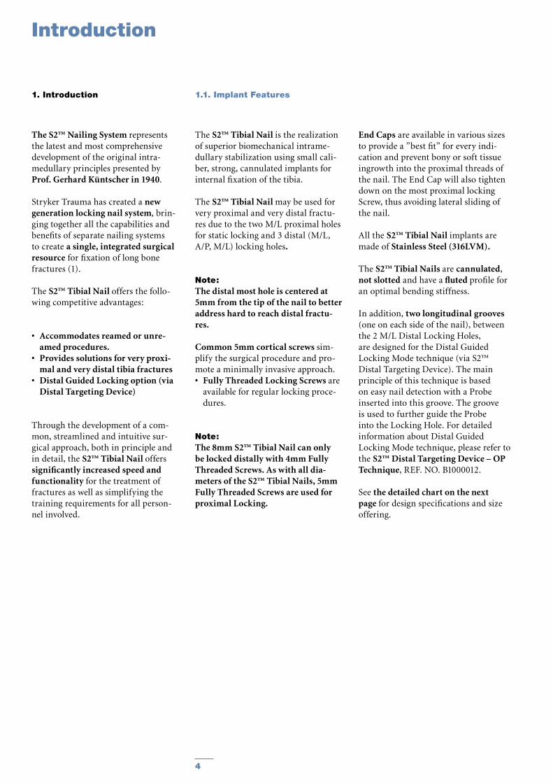
The S2™ Tibial Nail is the realization of superior biomechanical intrame-dullary stabilization using small cali-ber, strong, cannulated implants for internal fixation of the tibia.
The S2™ Tibial Nail may be used for very proximal and very distal fractu-res due to the two M/L proximal holes for static locking and 3 distal (M/L, A/P, M/L) locking holes.
Note:The distal most hole is centered at 5mm from the tip of the nail to better address hard to reach distal fractu-res.
Common 5mm cortical screws sim-plify the surgical procedure and pro-mote a minimally invasive approach.• Fully Threaded Locking Screws are
available for regular locking proce-dures.
Note:The 8mm S2™ Tibial Nail can only be locked distally with 4mm Fully Threaded Screws. As with all dia-meters of the S2™ Tibial Nails, 5mm Fully Threaded Screws are used for proximal Locking.
End Caps are available in various sizes to provide a ”best fit” for every indi-cation and prevent bony or soft tissue ingrowth into the proximal threads of the nail. The End Cap will also tighten down on the most proximal locking Screw, thus avoiding lateral sliding of the nail.
All the S2™ Tibial Nail implants are made of Stainless Steel (316LVM).
The S2™ Tibial Nails are cannulated, not slotted and have a fluted profile for an optimal bending stiffness.
In addition, two longitudinal grooves (one on each side of the nail), between the 2 M/L Distal Locking Holes, are designed for the Distal Guided Locking Mode technique (via S2™ Distal Targeting Device). The main principle of this technique is based on easy nail detection with a Probe inserted into this groove. The groove is used to further guide the Probe into the Locking Hole. For detailed information about Distal Guided Locking Mode technique, please refer to the S2™ Distal Targeting Device – OP Technique, REF. NO. B1000012.
See the detailed chart on the next page for design specifications and size offering.
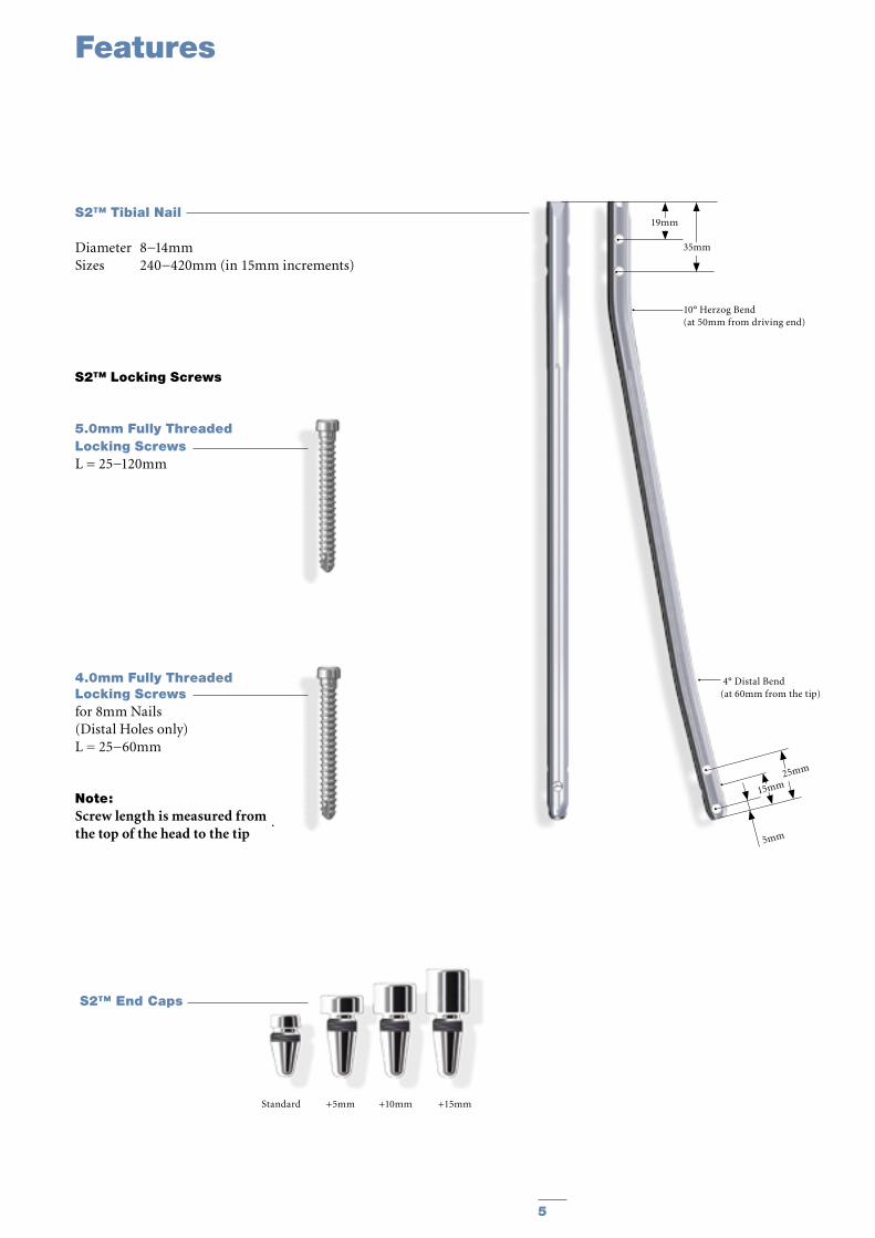
1.1. Implant Features
Features
5
4.0mm Fully Threaded Locking Screws for 8mm Nails (Distal Holes only)L = 25−60mm
Note: Screw length is measured from the top of the head to the tip
Standard +5mm +10mm +15mm
S2™ Tibial Nail
Diameter 8−14mmSizes 240−420mm (in 15mm increments)
S2™ End Caps
S2™ Locking Screws
5.0mm Fully Threaded Locking Screws L = 25−120mm
5mm
19mm
35mm
10° Herzog Bend(at 50mm from driving end)
25mm
15mm
4° Distal Bend(at 60mm from the tip)
6
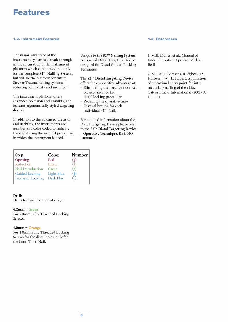
The major advantage of the instrument system is a break-through in the integration of the instrument platform which can be used not only for the complete S2™ Nailing System, but will be the platform for future Stryker Trauma nailing systems, reducing complexity and inventory.
The instrument platform offers advanced precision and usability, and features ergonomically styled targeting devices.
In addition to the advanced precision and usability, the instruments are number and color coded to indicate the step during the surgical procedure in which the instrument is used.
DrillsDrills feature color coded rings:
4.2mm = GreenFor 5.0mm Fully Threaded Locking Screws.
4.0mm = OrangeFor 4,0mm Fully Threaded Locking Screws for the distal holes, only for the 8mm Tibial Nail.
Unique to the S2™ Nailing System is a special Distal Targeting Device designed for Distal Guided Locking Technique.
The S2™ Distal Targeting Device offers the competitive advantage of:• Eliminating the need for fluorosco-
pic guidance for the distal locking procedure
• Reducing the operative time• Easy calibration for each
individual S2™ Nail.
For detailed information about the Distal Targeting Device please refer to the S2™ Distal Targeting Device – Operative Technique, REF. NO. B1000012.
1. M.E. Müller, et al., Manual of Internal Fixation, Springer Verlag, Berlin.
2. M.L.M.J. Goessens, R. Sijbers, J.S. Harbers, J.W.J.L. Stapert, Application of a proximal entry point for intra-medullary nailing of the tibia, Osteosinthese International (2001) 9: 101−104
Features
Step Color NumberOpening Red 1Reduction Brown 2Nail Introduction Green 3Guided Locking Light Blue 4Freehand Locking Dark Blue 5
1.2. Instrument Features 1.3. References
7
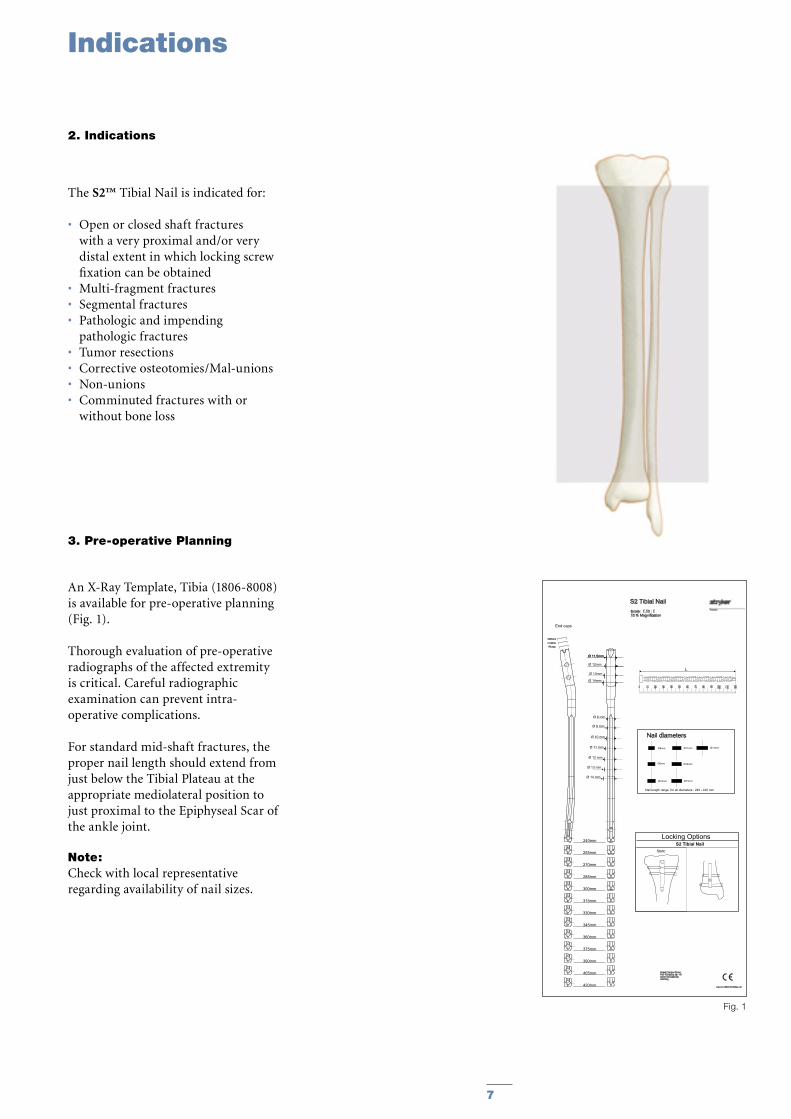
Fig. 1
S2 Tibial NailScale: 1,10 : 110 % Magnification
Cat.-No.:1806-8008/Rev.:00
Nail diameters
Nail length range for all diameters : 240 - 420 mm
Ø8mm Ø14mm
Ø12mm
Ø11mm
Ø10mm
Ø9mm
Ø13mm
Stryker Trauma GmbHProf.-Küntscher Str. 1-524232 SchönkirchenGermany
0 10 20 30 40 50 60 70 80 90 100 110 120
L
S2 Tibial NailLocking Options
Static
240mm
255mm
270mm
285mm
300mm
330mm
315mm
345mm
360mm
375mm
390mm
405mm
420mm
+5 mm+10mm+15mm
End caps
Ø 11,5mmØ 11,5mm
Ø 8 mm
Ø 10 mm
Ø 11 mm
Ø 12 mm
Ø 13 mm
Ø 14 mm
Ø 9 mm
Ø 12mm
Ø 13mm
Ø 14mm
The S2™ Tibial Nail is indicated for:
• Open or closed shaft fractures with a very proximal and/or very distal extent in which locking screw fixation can be obtained
• Multi-fragment fractures• Segmental fractures• Pathologic and impending
pathologic fractures• Tumor resections• Corrective osteotomies/Mal-unions• Non-unions• Comminuted fractures with or
without bone loss
3. Pre-operative Planning
An X-Ray Template, Tibia (1806-8008) is available for pre-operative planning (Fig. 1).
Thorough evaluation of pre-operative radiographs of the affected extremity is critical. Careful radiographic examination can prevent intra-operative complications.
For standard mid-shaft fractures, the proper nail length should extend from just below the Tibial Plateau at the appropriate mediolateral position to just proximal to the Epiphyseal Scar of the ankle joint.
Note:Check with local representative regarding availability of nail sizes.
Indications
2. Indications
8
Operative Technique
4. Operative Technique
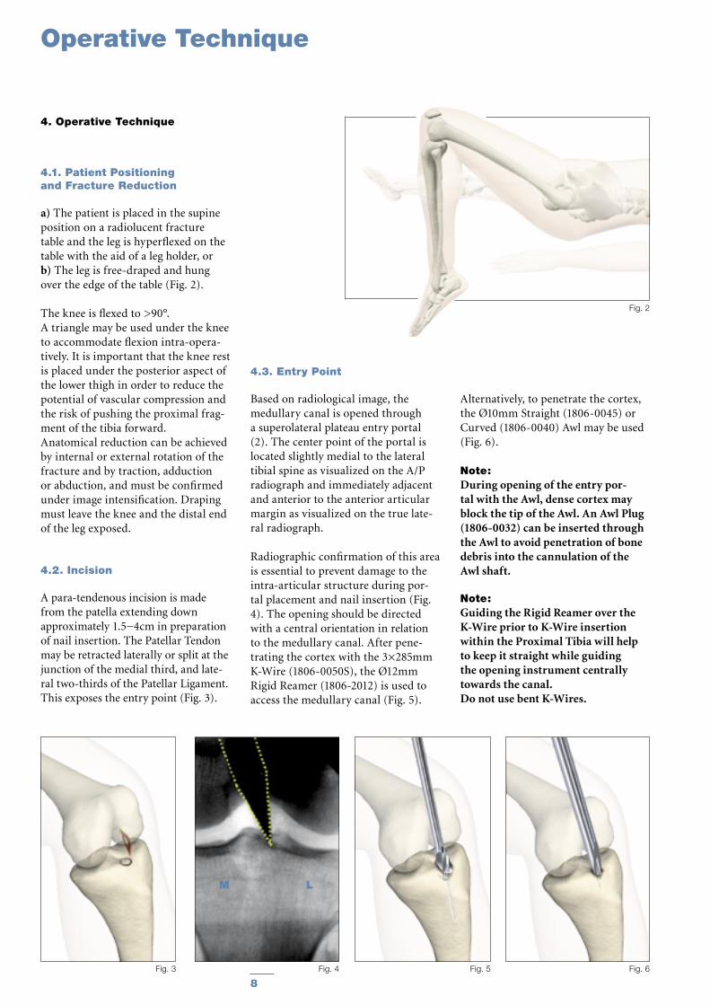
4.1. Patient Positioning and Fracture Reduction
a) The patient is placed in the supine position on a radiolucent fracture table and the leg is hyperflexed on the table with the aid of a leg holder, orb) The leg is free-draped and hung over the edge of the table (Fig. 2).
The knee is flexed to >90°. A triangle may be used under the knee to accommodate flexion intra-opera-tively. It is important that the knee rest is placed under the posterior aspect of the lower thigh in order to reduce the potential of vascular compression and the risk of pushing the proximal frag-ment of the tibia forward.Anatomical reduction can be achieved by internal or external rotation of the fracture and by traction, adduction or abduction, and must be confirmed under image intensification. Draping must leave the knee and the distal end of the leg exposed.
4.2. Incision
A para-tendenous incision is made from the patella extending down approximately 1.5−4cm in preparation of nail insertion. The Patellar Tendon may be retracted laterally or split at the junction of the medial third, and late-ral two-thirds of the Patellar Ligament. This exposes the entry point (Fig. 3).
Fig. 5 Fig. 6
Fig. 2
Fig. 3 Fig. 4
M L
4.3. Entry Point
Based on radiological image, the medullary canal is opened through a superolateral plateau entry portal (2). The center point of the portal is located slightly medial to the lateral tibial spine as visualized on the A/P radiograph and immediately adjacent and anterior to the anterior articular margin as visualized on the true late-ral radiograph.
Radiographic confirmation of this area is essential to prevent damage to the intra-articular structure during por-tal placement and nail insertion (Fig. 4). The opening should be directed with a central orientation in relation to the medullary canal. After pene-trating the cortex with the 3×285mm K-Wire (1806-0050S), the Ø12mm Rigid Reamer (1806-2012) is used to access the medullary canal (Fig. 5).
Alternatively, to penetrate the cortex, the Ø10mm Straight (1806-0045) or Curved (1806-0040) Awl may be used (Fig. 6).
Note:During opening of the entry por-tal with the Awl, dense cortex may block the tip of the Awl. An Awl Plug (1806-0032) can be inserted through the Awl to avoid penetration of bone debris into the cannulation of the Awl shaft.
Note: Guiding the Rigid Reamer over the K-Wire prior to K-Wire insertion within the Proximal Tibia will help to keep it straight while guiding the opening instrument centrally towards the canal.Do not use bent K-Wires.
9
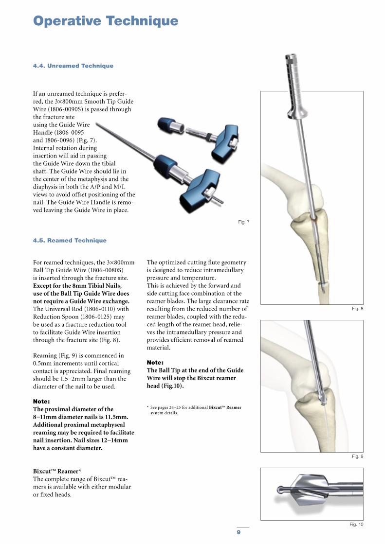
If an unreamed technique is prefer-red, the 3×800mm Smooth Tip Guide Wire (1806-0090S) is passed through the fracture site using the Guide Wire Handle (1806-0095 and 1806-0096) (Fig. 7). Internal rotation during insertion will aid in passing the Guide Wire down the tibial shaft. The Guide Wire should lie in the center of the metaphysis and the diaphysis in both the A/P and M/L views to avoid offset positioning of the nail. The Guide Wire Handle is remo-ved leaving the Guide Wire in place.
4.5. Reamed Technique
For reamed techniques, the 3×800mm Ball Tip Guide Wire (1806-0080S) is inserted through the fracture site. Except for the 8mm Tibial Nails, use of the Ball Tip Guide Wire does not require a Guide Wire exchange. The Universal Rod (1806-0110) with Reduction Spoon (1806-0125) may be used as a fracture reduction tool to facilitate Guide Wire insertion through the fracture site (Fig. 8).
Reaming (Fig. 9) is commenced in 0.5mm increments until cortical contact is appreciated. Final reaming should be 1.5−2mm larger than the diameter of the nail to be used.
Note: The proximal diameter of the 8−11mm diameter nails is 11.5mm. Additional proximal metaphyseal reaming may be required to facilitate nail insertion. Nail sizes 12−14mm have a constant diameter.
Bixcut™ Reamer*The complete range of Bixcut™ rea-mers is available with either modular or fixed heads.
The optimized cutting flute geometry is designed to reduce intramedullary pressure and temperature.This is achieved by the forward and side cutting face combination of the reamer blades. The large clearance rate resulting from the reduced number of reamer blades, coupled with the redu-ced length of the reamer head, relie-ves the intramedullary pressure and provides efficient removal of reamed material.
Note: The Ball Tip at the end of the Guide Wire will stop the Bixcut reamer head (Fig.10).
* See pages 24−25 for additional Bixcut™ Reamer system details.
Operative Technique
4.4. Unreamed Technique
Fig. 7
Fig. 10
Fig. 9
Fig. 8
10
Operative Technique
4.6. Nail Selection
DiameterThe diameter of the selected nail should be 1.5−2mm smaller than that of the last reamer used.
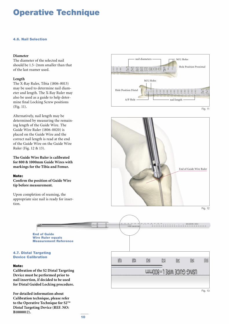
LengthThe X-Ray Ruler, Tibia (1806-8013) may be used to determine nail diam-eter and length. The X-Ray Ruler may also be used as a guide to help deter-mine final Locking Screw positions (Fig. 11).
Alternatively, nail length may be determined by measuring the remain-ing length of the Guide Wire. The Guide Wire Ruler (1806-0020) is placed on the Guide Wire and the correct nail length is read at the end of the Guide Wire on the Guide Wire Ruler (Fig. 12 & 13).
The Guide Wire Ruler is calibrated for 800 & 1000mm Guide Wires with markings for the Tibia and Femur.
Note:Confirm the position of Guide Wire tip before measurement.
Upon completion of reaming, the appropriate size nail is ready for inser-tion.
4.7. Distal Targeting Device Calibration
Note: Calibration of the S2 Distal Targeting Device must be performed prior to nail insertion, if decided to be used for Distal Guided Locking procedure.
For detailed information about Calibration technique, please refer to the Operative Technique for S2™ Distal Targeting Device (REF. NO: B1000012).
End of Guide Wire Ruler equals Measurement Reference
Fig. 13
Hole Position Proximal
Hole Position Distal
nail length
M/L Holes
A/P Hole
M/L Holes
nail diameters
Fig. 11
End of Guide Wire Ruler
Fig. 12
11
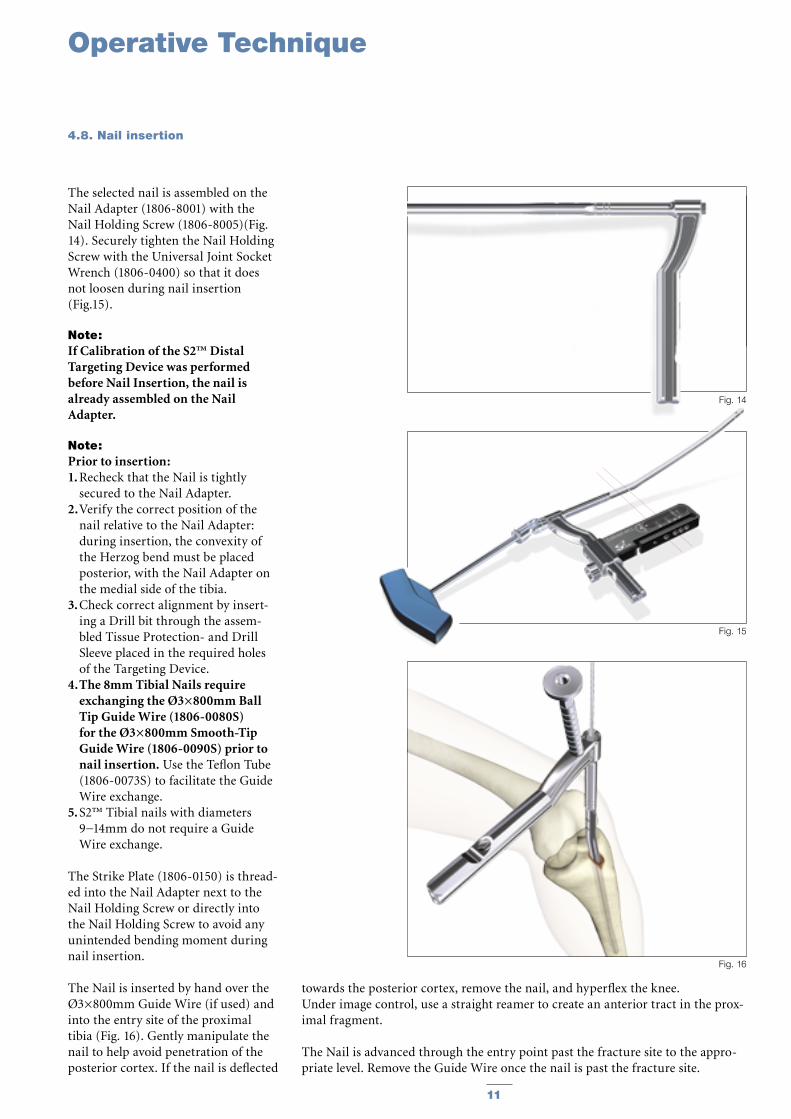
The selected nail is assembled on the Nail Adapter (1806-8001) with the Nail Holding Screw (1806-8005)(Fig. 14). Securely tighten the Nail Holding Screw with the Universal Joint Socket Wrench (1806-0400) so that it does not loosen during nail insertion (Fig.15).
Note: If Calibration of the S2™ Distal Targeting Device was performed before Nail Insertion, the nail is already assembled on the Nail Adapter.
Note: Prior to insertion:1. Recheck that the Nail is tightly
secured to the Nail Adapter.2. Verify the correct position of the
nail relative to the Nail Adapter: during insertion, the convexity of the Herzog bend must be placed posterior, with the Nail Adapter on the medial side of the tibia.
3. Check correct alignment by insert-ing a Drill bit through the assem-bled Tissue Protection- and Drill Sleeve placed in the required holes of the Targeting Device.
4. The 8mm Tibial Nails require exchanging the Ø3×800mm Ball Tip Guide Wire (1806-0080S) for the Ø3×800mm Smooth-Tip Guide Wire (1806-0090S) prior to nail insertion. Use the Teflon Tube (1806-0073S) to facilitate the Guide Wire exchange.
5. S2™ Tibial nails with diameters 9−14mm do not require a Guide Wire exchange.
The Strike Plate (1806-0150) is thread-ed into the Nail Adapter next to the Nail Holding Screw or directly into the Nail Holding Screw to avoid any unintended bending moment during nail insertion.
The Nail is inserted by hand over the Ø3×800mm Guide Wire (if used) and into the entry site of the proximal tibia (Fig. 16). Gently manipulate the nail to help avoid penetration of the posterior cortex. If the nail is deflected
towards the posterior cortex, remove the nail, and hyperflex the knee. Under image control, use a straight reamer to create an anterior tract in the prox-imal fragment.
The Nail is advanced through the entry point past the fracture site to the appro-priate level. Remove the Guide Wire once the nail is past the fracture site.
Operative Technique
4.8. Nail insertion
Fig. 16
Fig. 14
Fig. 15
12
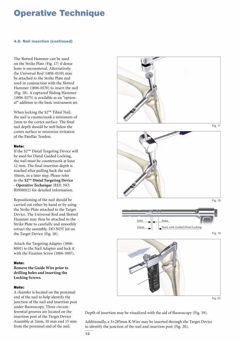
The Slotted Hammer can be used on the Strike Plate (Fig. 17) if dense bone is encountered. Alternatively, the Universal Rod (1806-0110) may be attached to the Strike Plate and used in conjunction with the Slotted Hammer (1806-0170) to insert the nail (Fig. 18). A captured Sliding Hammer (1806-0175) is available as an ”option-al“ addition to the basic instrument set.
When locking the S2™ Tibial Nail, the nail is countersunk a minimum of 2mm to the cortex surface. The final nail depth should be well below the cortex surface to minimize irritation of the Patellar Tendon.
Note: If the S2™ Distal Targeting Device will be used for Distal Guided Locking, the nail must be countersunk at least 12 mm. The final insertion depth is reached after pulling back the nail 10mm, in a later step. Please refer to the S2™ Distal Targeting Device - Operative Technique (REF. NO: B1000012) for detailed information.
Repositioning of the nail should be carried out either by hand or by using the Strike Plate attached to the Target Device. The Universal Rod and Slotted Hammer may then be attached to the Strike Plate to carefully and smoothly retract the assembly. DO NOT hit on the Target Device (Fig. 18).
Attach the Targeting Adapter (1806-8001) to the Nail Adapter and lock it with the Fixation Screw (1806-1007).
Note: Remove the Guide Wire prior to drilling holes and inserting the Locking Screws.
Note: A chamfer is located on the proximal end of the nail to help identify the junction of the nail and insertion post under fluoroscopy. Three circum-ferential grooves are located on the insertion post of the Target Device Assembly at 2mm, 10 mm and 15 mm from the proximal end of the nail.
Depth of insertion may be visualized with the aid of fluoroscopy (Fig. 19).
Additionally, a 3×285mm K-Wire may be inserted through the Target Device to identify the junction of the nail and insertion post (Fig. 20).
4.8. Nail insertion (continued)
Fig. 18
Fig. 17
Fig. 20
Static Static with Guided Distal Locking
2mm
12mm
Fig. 19
Operative Technique
13
Note: If the S2 Distal Targeting Device is going to be used, Distal Guided Locking should always be performed before Proximal Locking!
This is because the Distal Guided Locking technique requires free move-ment of the nail in the medullary canal.
For detailed information about the Distal Guided Locking procedure, please refer to the S2™ Distal Tar-geting Device - Operative Technique (REF. NO: B1000012).
Note: The 8mm Tibia Nail cannot be locked distally in a Guided Mode (via Distal Targeting Device). This is because 4mm Fully Threaded Screws must be used for distal locking of the 8mm Tibia Nail, while the Guided Locking procedure is only suitable for the 5mm Locking Screws.
4.10. Proximal Guided Locking Mode (Via Target Device)
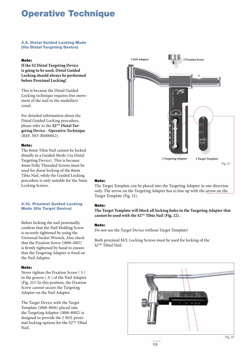
Before locking the nail proximally, confirm that the Nail Holding Screw is securely tightened by using the Universal Socket Wrench. Also check that the Fixation Screw (1806-1007) is firmly tightened by hand to ensure that the Targeting Adapter is fixed on the Nail Adapter.
Note: Never tighten the Fixation Screw ( 3 ) in the groove ( A ) of the Nail Adapter (Fig. 21)! In this position, the Fixation Screw cannot secure the Targeting Adapter on the Nail Adapter.
The Target Device with the Target Template (1806-8016) placed into the Targeting Adapter (1806-8002) is designed to provide the 2 M/L proxi-mal locking options for the S2™ Tibial Nail.
4 Target Template
3 Fixation Screw
2 Targeting Adapter
A
1 Nail Adapter
Fig. 21
Fig. 22
Note: The Target Template can be placed into the Targeting Adapter in one direction only. The arrow on the Targeting Adapter has to line up with the arrow on the Target Template (Fig. 21).
Note: The Target Template will block all locking holes in the Targeting Adapter that cannot be used with the S2™ Tibia Nail (Fig. 22).
Note: Do not use the Target Device without Target Template!
Both proximal M/L Locking Screws must be used for locking of the S2™ Tibial Nail.
Operative Technique
4.9. Distal Guided Locking Mode (Via Distal Targeting Device)
14
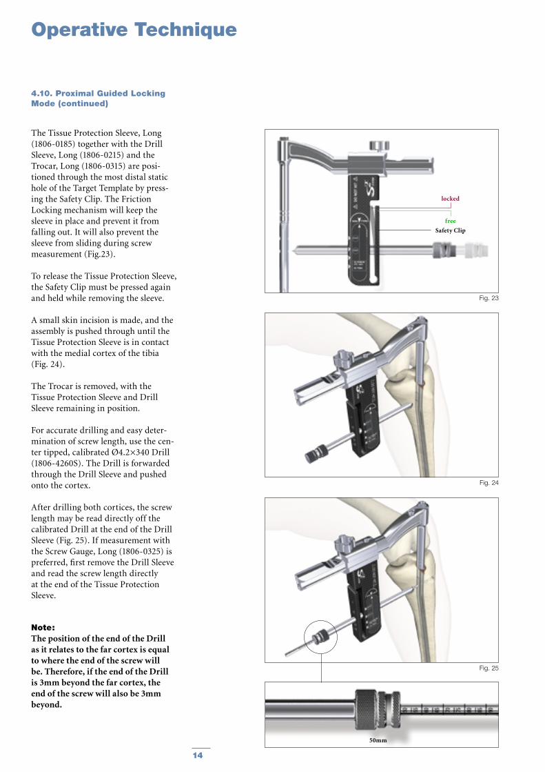
The Tissue Protection Sleeve, Long (1806-0185) together with the Drill Sleeve, Long (1806-0215) and the Trocar, Long (1806-0315) are posi-tioned through the most distal static hole of the Target Template by press-ing the Safety Clip. The Friction Locking mechanism will keep the sleeve in place and prevent it from falling out. It will also prevent the sleeve from sliding during screw measurement (Fig.23).
To release the Tissue Protection Sleeve, the Safety Clip must be pressed again and held while removing the sleeve.
A small skin incision is made, and the assembly is pushed through until the Tissue Protection Sleeve is in contact with the medial cortex of the tibia (Fig. 24).
The Trocar is removed, with the Tissue Protection Sleeve and Drill Sleeve remaining in position.
For accurate drilling and easy deter-mination of screw length, use the cen-ter tipped, calibrated Ø4.2×340 Drill (1806-4260S). The Drill is forwarded through the Drill Sleeve and pushed onto the cortex.
After drilling both cortices, the screw length may be read directly off the calibrated Drill at the end of the Drill Sleeve (Fig. 25). If measurement with the Screw Gauge, Long (1806-0325) is preferred, first remove the Drill Sleeve and read the screw length directly at the end of the Tissue Protection Sleeve.
Note: The position of the end of the Drill as it relates to the far cortex is equal to where the end of the screw will be. Therefore, if the end of the Drill is 3mm beyond the far cortex, the end of the screw will also be 3mm beyond.
free
Safety Clip
locked
Fig. 23
Fig. 24
4.10. Proximal Guided Locking Mode (continued)
Fig. 25
50mm
Operative Technique
15
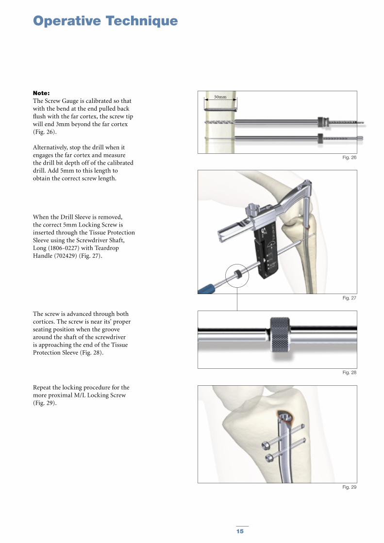
Note: The Screw Gauge is calibrated so that with the bend at the end pulled back flush with the far cortex, the screw tip will end 3mm beyond the far cortex (Fig. 26).
Alternatively, stop the drill when it engages the far cortex and measure the drill bit depth off of the calibrated drill. Add 5mm to this length to obtain the correct screw length.
When the Drill Sleeve is removed, the correct 5mm Locking Screw is inserted through the Tissue Protection Sleeve using the Screwdriver Shaft, Long (1806-0227) with Teardrop Handle (702429) (Fig. 27).
The screw is advanced through both cortices. The screw is near its’ proper seating position when the groove around the shaft of the screwdriver is approaching the end of the Tissue Protection Sleeve (Fig. 28).
Repeat the locking procedure for the more proximal M/L Locking Screw (Fig. 29).
Fig. 27
Fig. 28
Fig. 29
Operative Technique
Fig. 26
50mm
16
Operative Technique
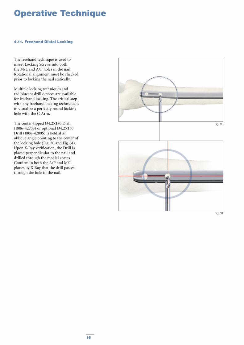
The freehand technique is used to insert Locking Screws into both the M/L and A/P holes in the nail. Rotational alignment must be checked prior to locking the nail statically.
Multiple locking techniques and radiolucent drill devices are available for freehand locking. The critical step with any freehand locking technique is to visualize a perfectly round locking hole with the C-Arm.
The center-tipped Ø4.2×180 Drill (1806-4270S) or optional Ø4.2×130 Drill (1806-4280S) is held at an oblique angle pointing to the center of the locking hole (Fig. 30 and Fig. 31). Upon X-Ray verification, the Drill is placed perpendicular to the nail and drilled through the medial cortex. Confirm in both the A/P and M/L planes by X-Ray that the drill passes through the hole in the nail.
4.11. Freehand Distal Locking
Fig. 31
Fig. 30
17
Operative Technique
Fig. 32
Green Ring
20mm
Fig. 33
Fig. 34
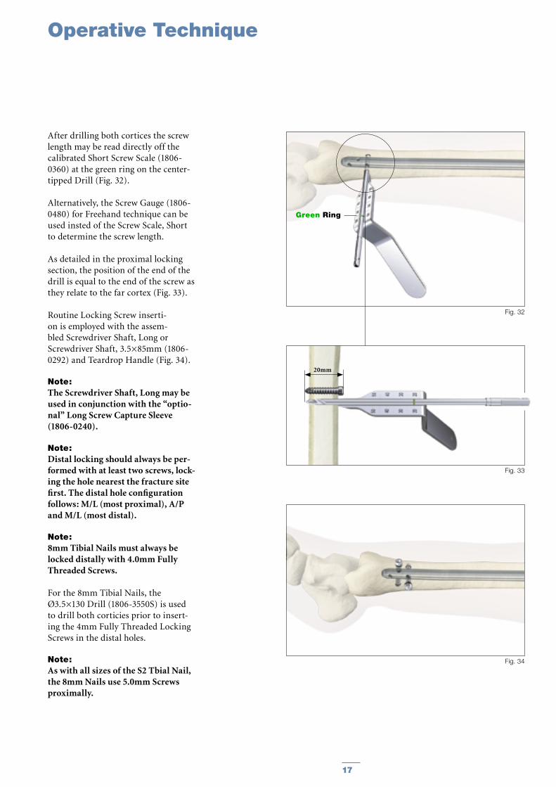
After drilling both cortices the screw length may be read directly off the calibrated Short Screw Scale (1806-0360) at the green ring on the center-tipped Drill (Fig. 32).
Alternatively, the Screw Gauge (1806-0480) for Freehand technique can be used insted of the Screw Scale, Short to determine the screw length.
As detailed in the proximal locking section, the position of the end of the drill is equal to the end of the screw as they relate to the far cortex (Fig. 33).
Routine Locking Screw inserti-on is employed with the assem-bled Screwdriver Shaft, Long or Screwdriver Shaft, 3.5×85mm (1806-0292) and Teardrop Handle (Fig. 34).
Note: The Screwdriver Shaft, Long may be used in conjunction with the “optio-nal” Long Screw Capture Sleeve (1806-0240).
Note: Distal locking should always be per-formed with at least two screws, lock-ing the hole nearest the fracture site first. The distal hole configuration follows: M/L (most proximal), A/P and M/L (most distal).
Note: 8mm Tibial Nails must always be locked distally with 4.0mm Fully Threaded Screws.
For the 8mm Tibial Nails, the Ø3.5×130 Drill (1806-3550S) is used to drill both corticies prior to insert-ing the 4mm Fully Threaded Locking Screws in the distal holes.
Note: As with all sizes of the S2 Tbial Nail, the 8mm Nails use 5.0mm Screws proximally.
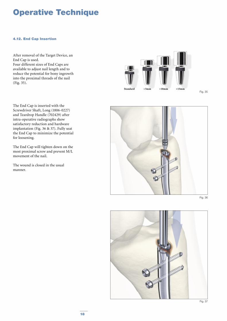
After removal of the Target Device, an End Cap is used.Four different sizes of End Caps are available to adjust nail length and to reduce the potential for bony ingrowth into the proximal threads of the nail (Fig. 35).
The End Cap is inserted with the Screwdriver Shaft, Long (1806-0227) and Teardrop Handle (702429) after intra-operative radiographs show satisfactory reduction and hardware implantation (Fig. 36 & 37). Fully seat the End Cap to minimize the potential for loosening.
The End Cap will tighten down on the most proximal screw and prevent M/L movement of the nail.
The wound is closed in the usual manner.
Fig. 35
Fig. 36
Fig. 37
18
Operative Technique
Standard +5mm +10mm +15mm
4.12. End Cap Insertion
19
Operative Technique
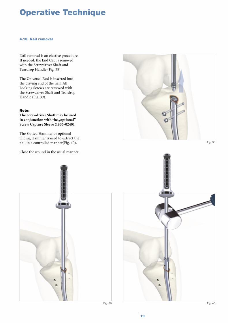
Nail removal is an elective procedure. If needed, the End Cap is removed with the Screwdriver Shaft and Teardrop Handle (Fig. 38).
The Universal Rod is inserted into the driving end of the nail. All Locking Screws are removed with the Screwdriver Shaft and Teardrop Handle (Fig. 39).
Note: The Screwdriver Shaft may be used in conjunction with the „optional” Screw Capture Sleeve (1806-0240).
The Slotted Hammer or optional Sliding Hammer is used to extract the nail in a controlled manner(Fig. 40).
Close the wound in the usual manner.
Fig. 38
Fig. 39 Fig. 40
4.13. Nail removal
1722-0824S1722-0825S1722-0827S1722-0828S1722-0830S1722-0831S1722-0833S1722-0834S1722-0836S1722-0837S1722-0839S1722-0840S1722-0842S
1722-0924S1722-0925S1722-0927S1722-0928S1722-0930S1722-0931S1722-0933S1722-0934S1722-0936S1722-0937S1722-0939S1722-0940S1722-0942S
1722-1024S1722-1025S1722-1027S1722-1028S1722-1030S1722-1031S1722-1033S1722-1034S1722-1036S1722-1037S1722-1039S1722-1040S1722-1042S
1722-1124S1722-1125S1722-1127S1722-1128S1722-1130S1722-1131S1722-1133S1722-1134S1722-1136S1722-1137S1722-1139S1722-1140S1722-1142S
1722-1224S1722-1225S1722-1227S1722-1228S1722-1230S1722-1231S1722-1233S1722-1234S1722-1236S1722-1237S1722-1239S1722-1240S1722-1242S
1722-1324S1722-1325S1722-1327S1722-1328S1722-1330S1722-1331S1722-1333S1722-1334S1722-1336S1722-1337S1722-1339S1722-1340S1722-1342S
1722-1424S1722-1425S1722-1427S1722-1428S1722-1430S1722-1431S1722-1433S1722-1434S1722-1436S1722-1437S1722-1439S1722-1440S1722-1442S
8.08.08.08.08.08.08.08.08.08.08.08.08.0
9.09.09.09.09.09.09.09.09.09.09.09.09.0
10.010.010.010.010.010.010.010.010.010.010.010.010.0
11.011.011.011.011.011.011.011.011.011.011.011.011.0
12.012.012.012.012.012.012.012.012.012.012.012.012.0
13.013.013.013.013.013.013.013.013.013.013.013.013.0
14.014.014.014.014.014.014.014.014.014.014.014.014.0
240255270285300315330345360375390405420
240255270285300315330345360375390405420
240255270285300315330345360375390405420
240255270285300315330345360375390405420
240255270285300315330345360375390405420
240255270285300315330345360375390405420
240255270285300315330345360375390405420
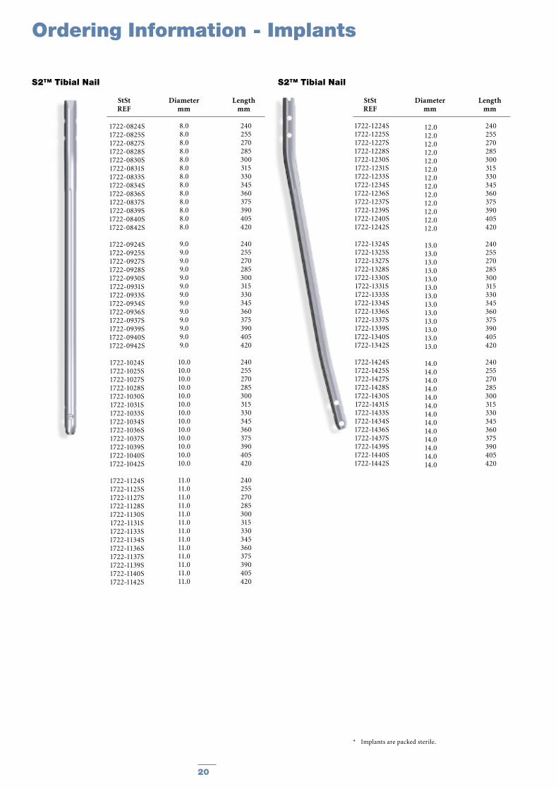
StSt Diameter Length REF mm mm
S2™ Tibial Nail S2™ Tibial Nail
Ordering Information - Implants
StSt Diameter Length REF mm mm
* Implants are packed sterile.
20
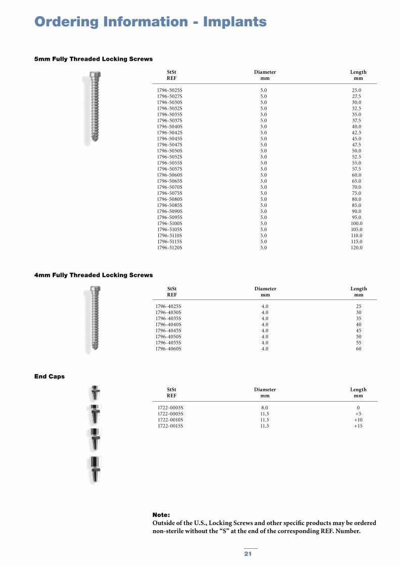
StSt Diameter Length REF mm mm
5mm Fully Threaded Locking Screws
StSt Diameter Length REF mm mm
End Caps
1722-0003S1722-0005S1722-0010S1722-0015S
8.011.511.511.5
0+5+10+15
1796-5025S1796-5027S1796-5030S1796-5032S1796-5035S1796-5037S1796-5040S1796-5042S1796-5045S1796-5047S 1796-5050S1796-5052S1796-5055S1796-5057S1796-5060S1796-5065S1796-5070S1796-5075S1796-5080S1796-5085S1796-5090S1796-5095S1796-5100S1796-5105S1796-5110S1796-5115S1796-5120S
5.05.05.05.05.05.05.05.05.05.05.05.05.05.05.05.05.05.05.05.05.05.05.05.05.05.05.0
25.027.530.032.535.037.540.042.545.047.550.052.555.057.560.065.070.075.080.085.090.095.0
100.0105.0110.0115.0120.0
StSt Diameter Length REF mm mm
4mm Fully Threaded Locking Screws
1796-4025S1796-4030S1796-4035S1796-4040S1796-4045S1796-4050S1796-4055S1796-4060S
4.04.04.04.04.04.04.04.0
2530354045505560
Ordering Information - Implants
Note: Outside of the U.S., Locking Screws and other specific products may be ordered non-sterile without the “S” at the end of the corresponding REF. Number.
21
X-Ray Ruler, Tibia
Guide Wire Ruler
Awl, Curved, Ø10mm
K-Wire 3×285mm (outside of U.S.)
Guide Wire Handle
Guide Wire Handle Chuck
Universal Rod
Reduction Spoon
Wrench 8mm/10mm
Strike Plate
S2 Nail Holding Screw (2 each)
Slotted Hammer
Tissue Protection Sleeve, Long
Drill Sleeve, Long
Screwdriver Shaft AO, Long
Screw Driver Shaft, 3.5×85mm
Trocar, Long
Screw Gauge, Long
Long Screw Gauge (20mm−80mm)
Socket Wrench, Universal Joint 10mm
Drill Ø4.2×340mm, AO, (outside of U.S.)
Drill Ø4.2×180mm, AO, (outside of U.S.)
Teardrop Handle, AO coupling
Rigid Reamer, Ø12mm
Target Template
Sleeve Fixation Screw
Target Device, S2 (3 components)
S2 Nail Adapter
S2 Targeting Adapter
Fixation Screw
Dedicated Instrument Box, S2
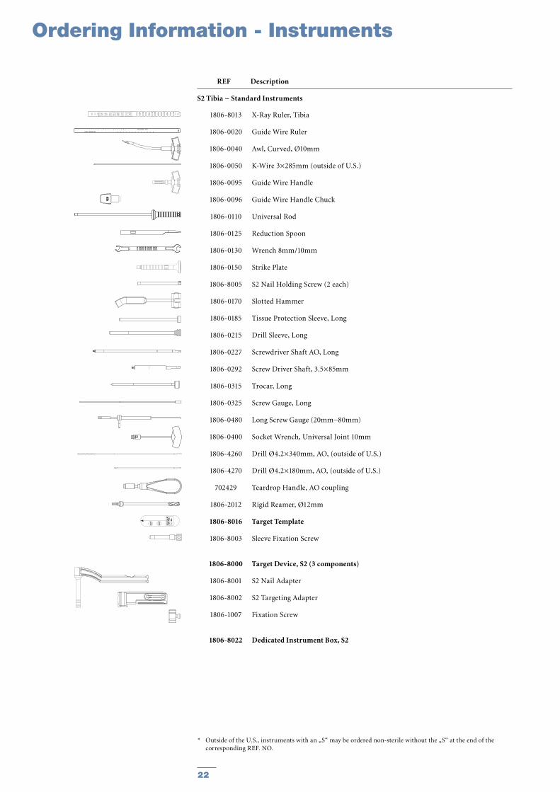
1806-8013
1806-0020
1806-0040
1806-0050
1806-0095
1806-0096
1806-0110
1806-0125
1806-0130
1806-0150
1806-8005
1806-0170
1806-0185
1806-0215
1806-0227
1806-0292
1806-0315
1806-0325
1806-0480
1806-0400
1806-4260
1806-4270
702429
1806-2012
1806-8016
1806-8003
1806-8000
1806-8001
1806-8002
1806-1007
1806-8022
* Outside of the U.S., instruments with an „S“ may be ordered non-sterile without the „S“ at the end of the corresponding REF. NO.
Ordering Information - Instruments
REF Description
S2 Tibia − Standard Instruments
22
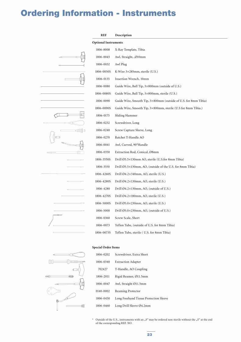
X-Ray Template, Tibia
Awl, Straight, ‚Ø10mm
Awl Plug
K-Wire 3×285mm, sterile (U.S.)
Insertion Wrench, 10mm
Guide Wire, Ball Tip, 3×800mm (outside of U.S.)
Guide Wire, Ball Tip, 3×800mm, sterile (U.S.)
Guide Wire, Smooth Tip, 3×800mm (outside of U.S. for 8mm Tibia)
Guide Wire, Smooth Tip, 3×800mm, sterile (U.S for 8mm Tibia.)
Sliding Hammer
Screwdriver, Long
Screw Capture Sleeve, Long
Ratchet T-Handle AO
Awl, Curved, 90°Handle
Extraction Rod, Conical, Ø8mm
Drill Ø3.5×130mm AO, sterile (U.S.for 8mm Tibia)
Drill Ø3.5×130mm, AO, (outside of the U.S. for 8mm Tibia)
Drill Ø4.2×340mm, AO, sterile (U.S.)
Drill Ø4.2×130mm, AO, sterile (U.S.)
Drill Ø4.2×130mm, AO, (outside of U.S.)
Drill Ø4.2×180mm, AO, sterile (U.S.)
Drill Ø5.0×230mm, AO, sterile (U.S.)
Drill Ø5.0×230mm, AO, (outside of U.S.)
Screw Scale, Short
Teflon Tube, (outside of U.S. for 8mm Tibia)
Teflon Tube, sterile ( U.S. for 8mm Tibia)
Screwdriver, Extra Short
Extraction Adapter
T-Handle, AO Coupling
Rigid Reamer, Ø11.5mm
Awl, Straight Ø11.5mm
Reaming Protector
Long Freehand Tissue Protection Sleeve
Long Drill Sleeve Ø4.2mm
1806-8008
1806-0045
1806-0032
1806-0050S
1806-0135
1806-0080
1806-0080S
1806-0090
1806-0090S
1806-0175
1806-0232
1806-0240
1806-0270
1806-0041
1806-0350
1806-3550S
1806-3550
1806-4260S
1806-4280S
1806-4280
1806-4270S
1806-5000S
1806-5000
1806-0360
1806-0073
1806-0073S
1806-0202
1806-0340
702427
1806-2011
1806-0047
0140-0002
1806-0450
1806-0460
* Outside of the U.S., instruments with an „S“ may be ordered non-sterile without the „S“ at the end of the corresponding REF. NO.
REF Description
Optional Instruments
Special Order Items
Ordering Information - Instruments
23
Ordering Information - InstrumentsOrdering Information - Instruments
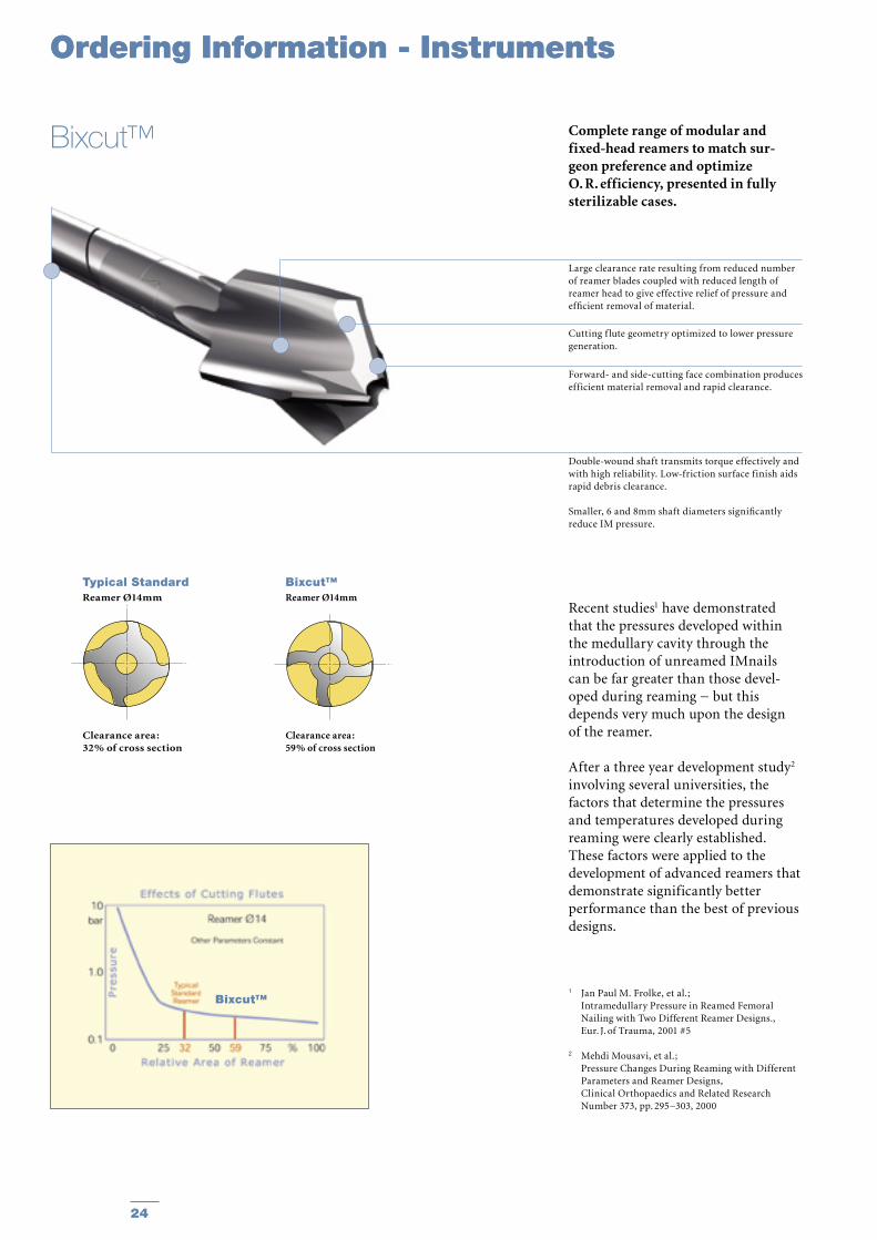
Complete range of modular and fixed-head reamers to match sur-geon preference and optimize O. R. efficiency, presented in fully sterilizable cases.
Recent studies1 have demonstrated that the pressures developed within the medullary cavity through the introduction of unreamed IMnails can be far greater than those devel-oped during reaming − but this depends very much upon the design of the reamer.
After a three year development study2 involving several universities, the factors that determine the pressures and temperatures developed during reaming were clearly established. These factors were applied to the development of advanced reamers that demonstrate significantly better performance than the best of previous designs.
1 Jan Paul M. Frolke, et al. ; Intramedullary Pressure in Reamed Femoral
Nailing with Two Different Reamer Designs., Eur. J. of Trauma, 2001 #5
2 Mehdi Mousavi, et al.; Pressure Changes During Reaming with Different
Parameters and Reamer Designs, Clinical Orthopaedics and Related Research
Number 373, pp. 295−303, 2000
Large clearance rate resulting from reduced number of reamer blades coupled with reduced length of reamer head to give effective relief of pressure and efficient removal of material.
Cutting f lute geometry optimized to lower pressure generation.
Forward- and side-cutting face combination produces efficient material removal and rapid clearance.
Double-wound shaft transmits torque effectively and with high reliability. Low-friction surface finish aids rapid debris clearance.
Smaller, 6 and 8mm shaft diameters significantly reduce IM pressure.
Bixcut™
Typical StandardReamer Ø14mm
Clearance area :32% of cross section
Bixcut™Reamer Ø14mm
Clearance area :59% of cross section
Bixcut™
24
REF Description Diameter mm
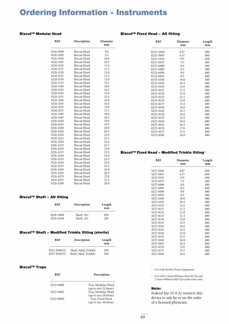
Bixcut™ Modular Head
REF Diameter Length mm mm
Bixcut™ Fixed Head − AO fitting
REF Description Length mm
Bixcut™ Shaft − AO fitting
REF Description Length mm
Bixcut™ Shaft − Modified Trinkle fitting (sterile)
REF Description
Bixcut™ Trays
REF Diameter Length mm mm
Bixcut™ Fixed Head − Modified Trinkle fitting+
0226-30900226-30950226-31000226-31050226-31100226-31150226-31200226-31250226-31300226-31350226-31400226-31450226-31500226-31550226-31600226-31650226-31700226-31750226-31800226-41850226-41900226-41950226-42000226-42050226-42100226-42150226-42200226-42250226-42300226-42350226-42400226-42450226-42500226-42550226-42600226-42650226-42700226-42750226-4280
Bixcut HeadBixcut HeadBixcut HeadBixcut HeadBixcut HeadBixcut HeadBixcut HeadBixcut HeadBixcut HeadBixcut HeadBixcut HeadBixcut HeadBixcut HeadBixcut HeadBixcut HeadBixcut HeadBixcut HeadBixcut HeadBixcut HeadBixcut HeadBixcut HeadBixcut HeadBixcut HeadBixcut HeadBixcut HeadBixcut HeadBixcut HeadBixcut HeadBixcut HeadBixcut HeadBixcut HeadBixcut HeadBixcut HeadBixcut HeadBixcut HeadBixcut HeadBixcut HeadBixcut HeadBixcut Head
9.09.5
10.010.511.011.512.012.513.013.514.014.515.015.516.016.517.017.518.018.519.019.520.020.521.021.522.022.523.023.524.024.525.025.526.026.527.027.528.0
0226-30000226-8240
Shaft, AOShaft, AO
450240
0227-3000(S)0227-8240(S)
Shaft, Mod. TrinkleShaft, Mod. Trinkle+
450240
0225-6000
0225-6001
0225-8000
Tray, Modular Head (up to size 22.0mm)Tray, Modular Head (up to size 28.0mm)
Tray, Fixed Head (up to size 18.0mm)
0227-50600227-50650227-50700227-60750227-60800227-60850227-60900227-60950227-61000227-61050227-61100227-81150227-81200227-81250227-81300227-81350227-81400227-81450227-81500227-81550227-81600227-81650227-81700227-81750227-8180
6.0*6.5*7.0*7.58.08.59.09.5
10.010.511.011.512.012.513.013.514.014.515.015.516.016.517.017.518.0
400400400480480480480480480480480480480480480480480480480480480480480480480
0225-50600225-50650225-50700225-60750225-60800225-60850225-60900225-60950225-61000225-61050225-61100225-81150225-81200225-81250225-81300225-81350225-81400225-81450225-81500225-81550225-81600225-81650225-81700225-81750225-8180
6.0*6.5*7.0*7.58.08.59.09.5
10.010.511.011.512.012.513.013.514.014.515.015.516.016.517.017.518.0
400400400480480480480480480480480480480480480480480480480480480480480480480
+ Use with Stryker Power Equipment
* Use with 2.2mm×800mm Smooth Tip and 2.5mm×800mm Ball Tip Guide wires only.
Note:Federal law (U.S.A) restricts this device to sale by or on the order of a licensed physician.
Ordering Information - Instruments
25

Notes
26

Notes
27

The information presented in this brochure is intended to demonstrate a Stryker product. Always refer to the package insert, product label and/or user instructions before using any Stryker product. Products may not be available in all markets. Product availability is subject to the regulatory or medical practices that govern individual markets. Please contact your Stryker representative if you have questions about the availability of Stryker products in your area.
Products referenced with ™ designation are trademarks of Stryker. Products referenced with ® designation are registered trademarks of Stryker.
Literature Number : B1000014LOT B3104
Copyright © 2004 StrykerPrinted in Germany
Stryker Trauma GmbHProf.-Küntscher-Strasse 1-5D-24232 SchönkirchenGermany
www.trauma.stryker.com