Embed Size (px)
Citation preview
Standards
Quality Assurance
Excitation and Voltage Regulators
AVR Type AS440 MX341 MX321
Voltage Regulation ± 1% ± 1% ± 0.5%
AVR Power Self-Excited PMG PMG
Full Load Excitation Voltage (V) 44
Full Load Excitation Current (A) 2.6
Exciter Time Constant (seconds) 0.099
with 4% Engine Governing
No Load Excitation Voltage (V) 9.9 - 8.5
No Load Excitation Current (A) 0.62 - 0.54
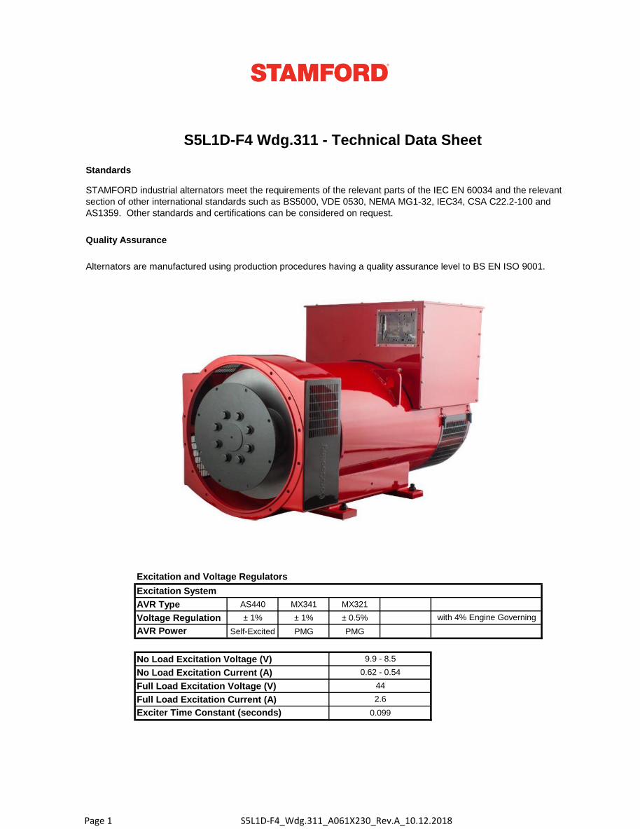
S5L1D-F4 Wdg.311 - Technical Data Sheet
STAMFORD industrial alternators meet the requirements of the relevant parts of the IEC EN 60034 and the relevant
section of other international standards such as BS5000, VDE 0530, NEMA MG1-32, IEC34, CSA C22.2-100 and
AS1359. Other standards and certifications can be considered on request.
Excitation System
Alternators are manufactured using production procedures having a quality assurance level to BS EN ISO 9001.
Page 1 S5L1D-F4_Wdg.311_A061X230_Rev.A_10.12.2018
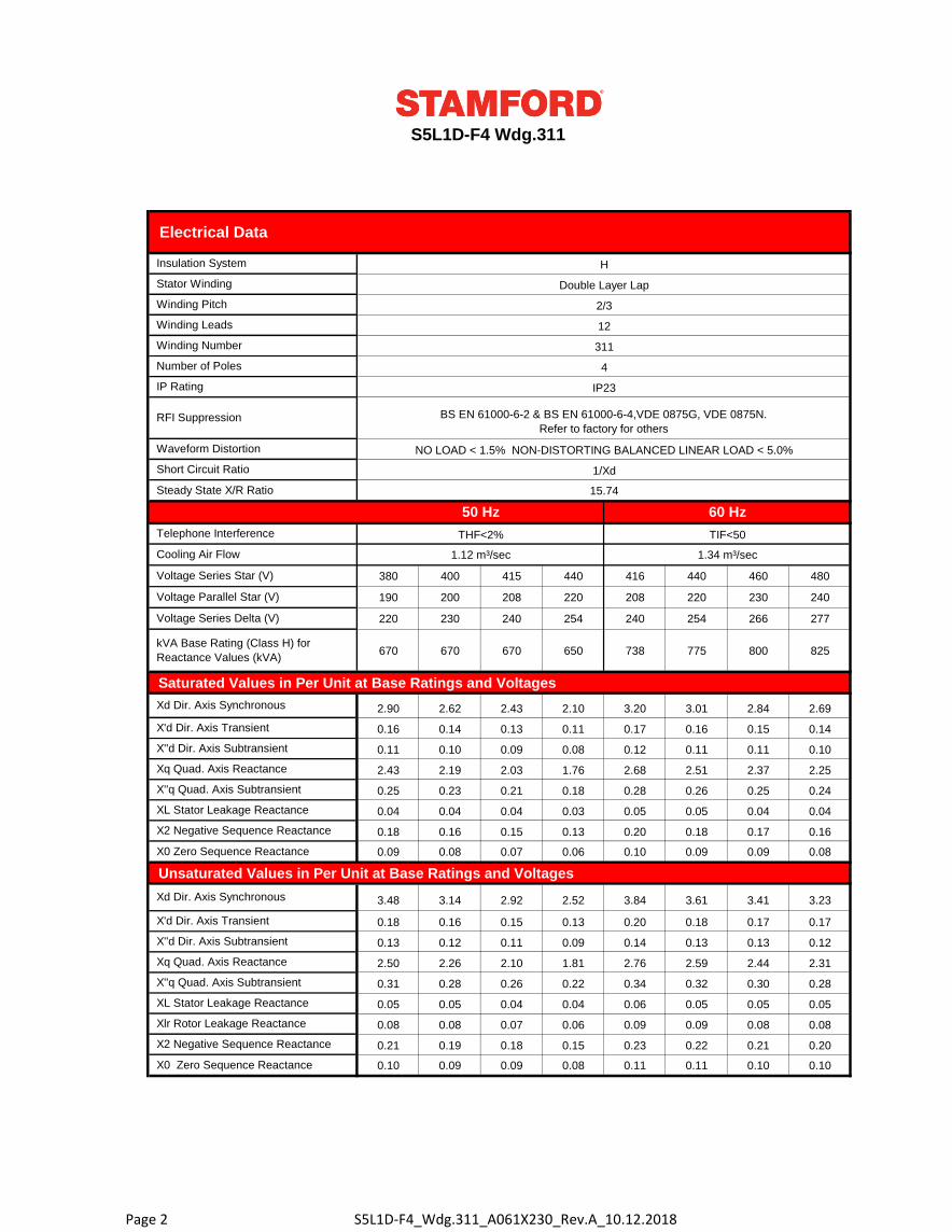
50 Hz 60 Hz
THF<2% TIF<50
1.12 m³/sec 1.34 m³/sec
380 400 415 440 416 440 460 480
190 200 208 220 208 220 230 240
220 230 240 254 240 254 266 277
670 670 670 650 738 775 800 825
Saturated Values in Per Unit at Base Ratings and Voltages
2.90 2.62 2.43 2.10 3.20 3.01 2.84 2.69
0.16 0.14 0.13 0.11 0.17 0.16 0.15 0.14
0.11 0.10 0.09 0.08 0.12 0.11 0.11 0.10
2.43 2.19 2.03 1.76 2.68 2.51 2.37 2.25
0.25 0.23 0.21 0.18 0.28 0.26 0.25 0.24
0.04 0.04 0.04 0.03 0.05 0.05 0.04 0.04
0.18 0.16 0.15 0.13 0.20 0.18 0.17 0.16
0.09 0.08 0.07 0.06 0.10 0.09 0.09 0.08
Unsaturated Values in Per Unit at Base Ratings and Voltages
3.48 3.14 2.92 2.52 3.84 3.61 3.41 3.23
0.18 0.16 0.15 0.13 0.20 0.18 0.17 0.17
0.13 0.12 0.11 0.09 0.14 0.13 0.13 0.12
2.50 2.26 2.10 1.81 2.76 2.59 2.44 2.31
0.31 0.28 0.26 0.22 0.34 0.32 0.30 0.28
0.05 0.05 0.04 0.04 0.06 0.05 0.05 0.05
0.08 0.08 0.07 0.06 0.09 0.09 0.08 0.08
0.21 0.19 0.18 0.15 0.23 0.22 0.21 0.20
0.10 0.09 0.09 0.08 0.11 0.11 0.10 0.10
X'd Dir. Axis Transient
X''d Dir. Axis Subtransient
Xq Quad. Axis Reactance
X''q Quad. Axis Subtransient
XL Stator Leakage Reactance
Xlr Rotor Leakage Reactance
X2 Negative Sequence Reactance
X0 Zero Sequence Reactance
Xd Dir. Axis Synchronous
X''q Quad. Axis Subtransient
XL Stator Leakage Reactance
X2 Negative Sequence Reactance
X0 Zero Sequence Reactance
Xq Quad. Axis Reactance
Xd Dir. Axis Synchronous
X'd Dir. Axis Transient
X''d Dir. Axis Subtransient
Voltage Parallel Star (V)
Voltage Series Delta (V)
Cooling Air Flow
Voltage Series Star (V)
kVA Base Rating (Class H) for
Reactance Values (kVA)
Telephone Interference
Number of Poles
Waveform Distortion
4
IP Rating IP23
RFI Suppression BS EN 61000-6-2 & BS EN 61000-6-4,VDE 0875G, VDE 0875N.
Refer to factory for others
NO LOAD < 1.5% NON-DISTORTING BALANCED LINEAR LOAD < 5.0%
Short Circuit Ratio 1/Xd
Steady State X/R Ratio 15.74
Winding Pitch 2/3
Winding Leads 12
Winding Number 311
S5L1D-F4 Wdg.311
Electrical Data
Insulation System H
Stator Winding Double Layer Lap
Page 2 S5L1D-F4_Wdg.311_A061X230_Rev.A_10.12.2018
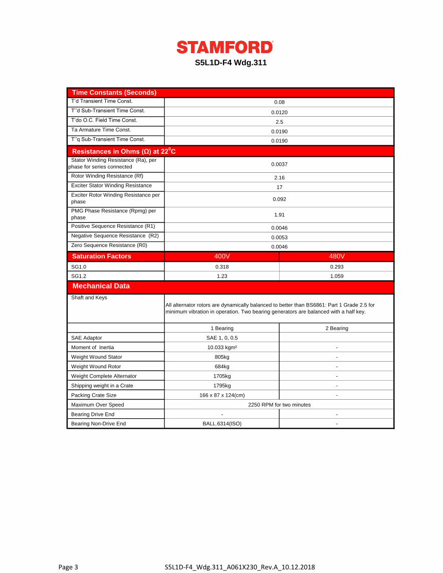
400V 480V
SG1.0 0.318 0.293
SG1.2 1.23 1.059
Packing Crate Size 166 x 87 x 124(cm) -
Maximum Over Speed 2250 RPM for two minutes
Bearing Drive End - -
Bearing Non-Drive End BALL.6314(ISO) -
Shipping weight in a Crate 1795kg -
Weight Complete Alternator 1705kg -
Weight Wound Rotor 684kg -
Moment of Inertia 10.033 kgm² -
Weight Wound Stator 805kg -
1 Bearing 2 Bearing
SAE Adaptor SAE 1, 0, 0.5
Shaft and Keys
All alternator rotors are dynamically balanced to better than BS6861: Part 1 Grade 2.5 for
minimum vibration in operation. Two bearing generators are balanced with a half key.
Negative Sequence Resistance (R2) 0.0053
Zero Sequence Resistance (R0) 0.0046
Saturation Factors
Mechanical Data
Exciter Rotor Winding Resistance per
phase 0.092
PMG Phase Resistance (Rpmg) per
phase1.91
Positive Sequence Resistance (R1) 0.0046
Resistances in Ohms (Ω) at 220C
Stator Winding Resistance (Ra), per
phase for series connected 0.0037
Rotor Winding Resistance (Rf) 2.16
S5L1D-F4 Wdg.311
Time Constants (Seconds)
T’d Transient Time Const. 0.08
T’’d Sub-Transient Time Const. 0.0120
Exciter Stator Winding Resistance 17
T’do O.C. Field Time Const. 2.5
Ta Armature Time Const. 0.0190
T’’q Sub-Transient Time Const. 0.0190
Page 3 S5L1D-F4_Wdg.311_A061X230_Rev.A_10.12.2018
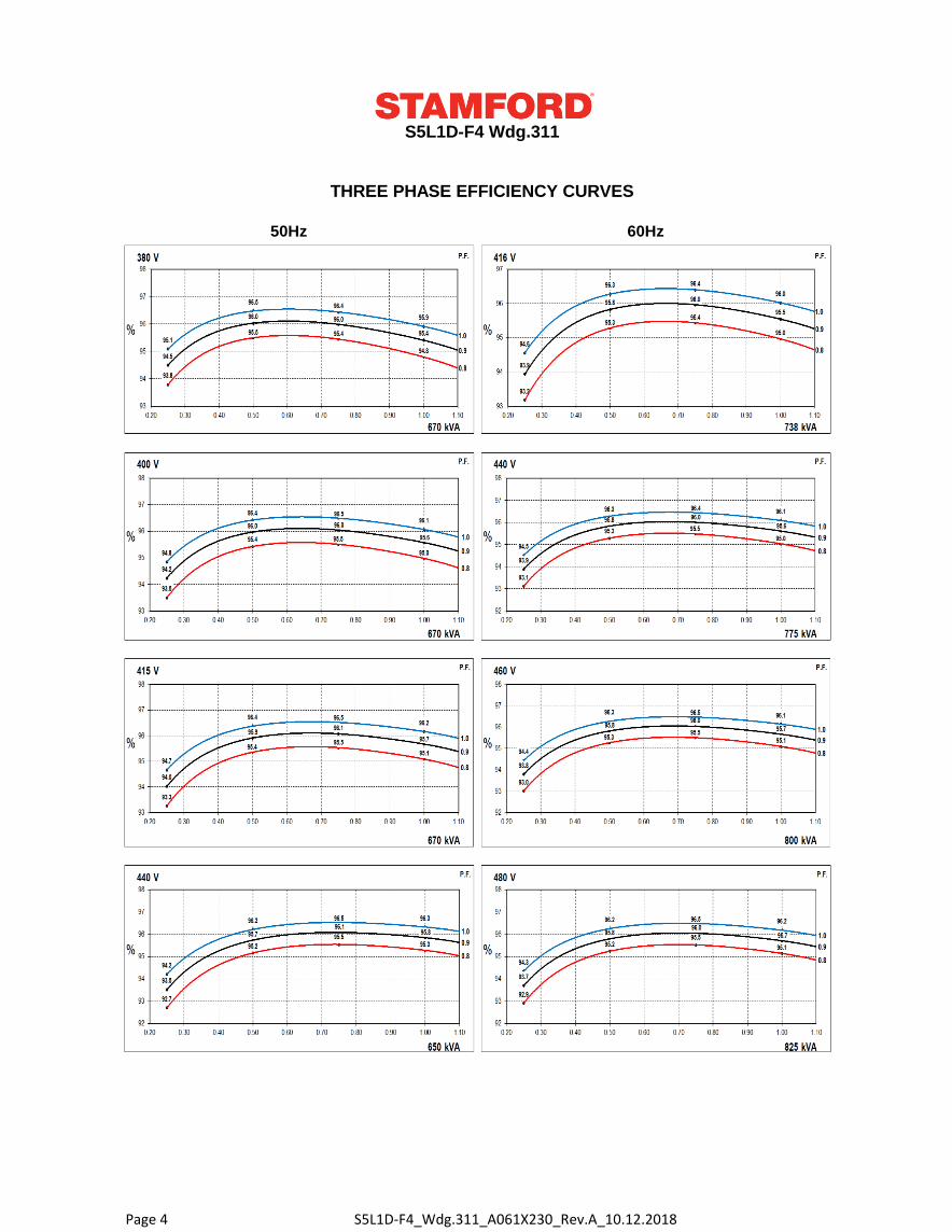
50Hz 60Hz
S5L1D-F4 Wdg.311
THREE PHASE EFFICIENCY CURVES
Page 4 S5L1D-F4_Wdg.311_A061X230_Rev.A_10.12.2018
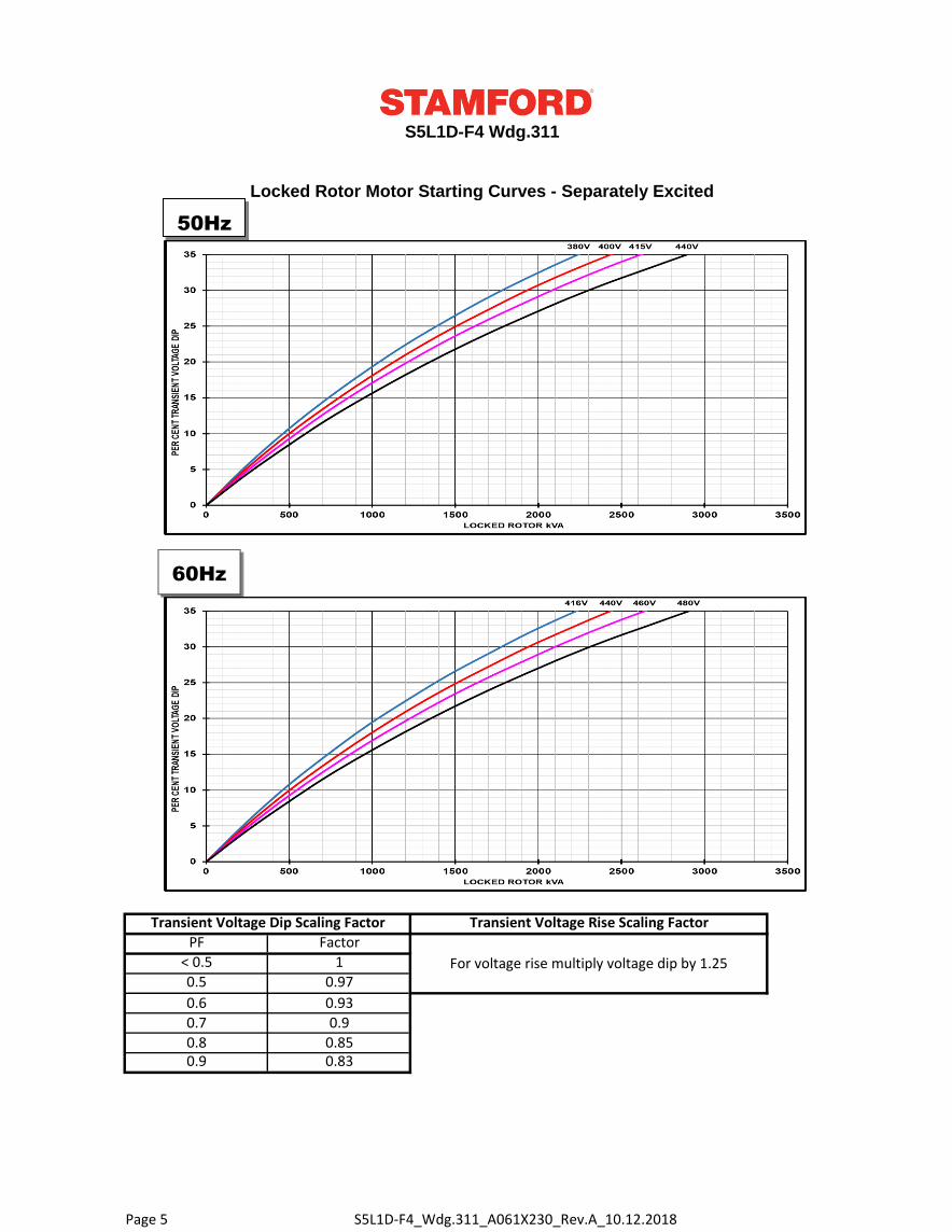
For voltage rise multiply voltage dip by 1.25
S5L1D-F4 Wdg.311
0.9 0.83
0.6 0.93
0.7 0.9
0.8 0.85
PF Factor
< 0.5 1
0.5 0.97
Locked Rotor Motor Starting Curves - Separately Excited
Transient Voltage Dip Scaling Factor Transient Voltage Rise Scaling Factor
50Hz
60Hz
Page 5 S5L1D-F4_Wdg.311_A061X230_Rev.A_10.12.2018
S5L1D-F4 Wdg.311
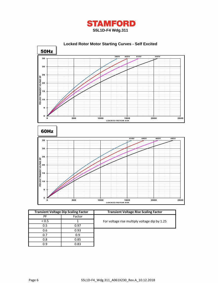
Locked Rotor Motor Starting Curves - Self Excited
Transient Voltage Dip Scaling Factor Transient Voltage Rise Scaling Factor
For voltage rise multiply voltage dip by 1.25
0.9 0.83
0.6 0.93
0.7 0.9
0.8 0.85
PF Factor
< 0.5 1
0.5 0.97
50Hz
60Hz
S5L1D-F4_Wdg.311_A061X230_Rev.A_10.12.2018Page 6
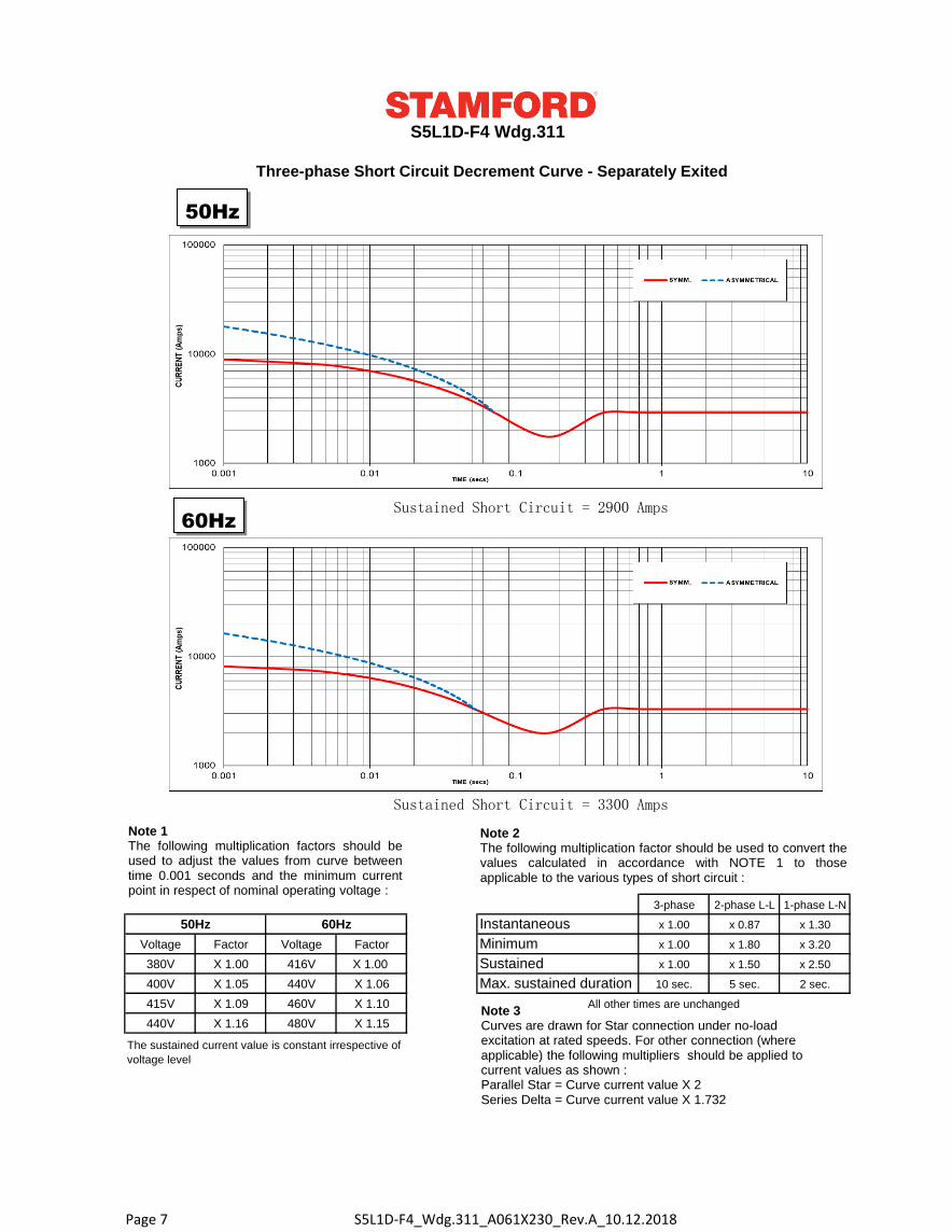
3-phase 2-phase L-L 1-phase L-N
50Hz 60Hz Instantaneous x 1.00 x 0.87 x 1.30
Voltage Factor Voltage Factor Minimum x 1.00 x 1.80 x 3.20
380V X 1.00 416V X 1.00 Sustained x 1.00 x 1.50 x 2.50
400V X 1.05 440V X 1.06 Max. sustained duration 10 sec. 5 sec. 2 sec.
415V X 1.09 460V X 1.10
440V X 1.16 480V X 1.15
The sustained current value is constant irrespective of
voltage level
All other times are unchanged
S5L1D-F4 Wdg.311
Three-phase Short Circuit Decrement Curve - Separately Exited
Sustained Short Circuit = 2900 Amps
Sustained Short Circuit = 3300 Amps
Note 1The following multiplication factors should beused to adjust the values from curve betweentime 0.001 seconds and the minimum currentpoint in respect of nominal operating voltage :
Note 2The following multiplication factor should be used to convert thevalues calculated in accordance with NOTE 1 to thoseapplicable to the various types of short circuit :
Note 3Curves are drawn for Star connection under no-load excitation at rated speeds. For other connection (where applicable) the following multipliers should be applied to current values as shown : Parallel Star = Curve current value X 2Series Delta = Curve current value X 1.732
50Hz
60Hz
S5L1D-F4_Wdg.311_A061X230_Rev.A_10.12.2018Page 7
S5L1D-F4 Wdg.311
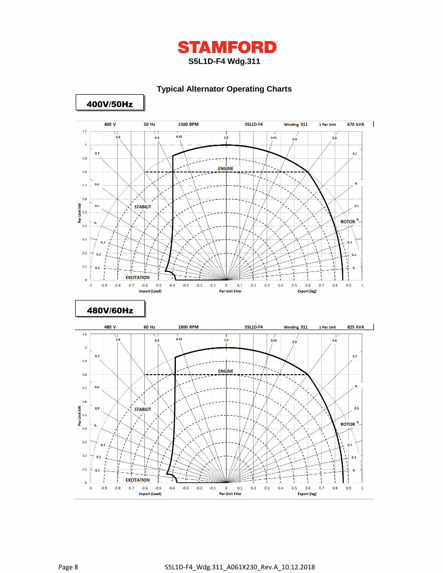
Typical Alternator Operating Charts
400V/50Hz
480V/60Hz
S5L1D-F4_Wdg.311_A061X230_Rev.A_10.12.2018Page 8
S5L1D-F4 Wdg.311
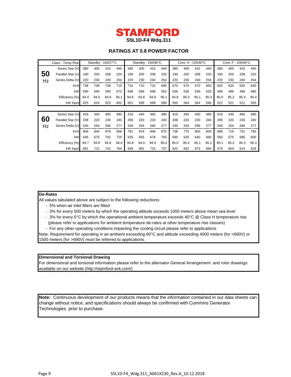
RATINGS AT 0.8 POWER FACTOR
Class - Temp Rise
Series Star (V) 380 400 415 440 380 400 415 440 380 400 415 440 380 400 415 440
Parallel Star (V) 190 200 208 220 190 200 208 220 190 200 208 220 190 200 208 220
Series Delta (V) 220 230 240 254 220 230 240 254 220 230 240 254 220 230 240 254
kVA 738 738 738 715 710 710 710 690 670 670 670 650 620 620 620 600
kW 590 590 590 572 568 568 568 552 536 536 536 520 496 496 496 480
Efficiency (%) 94.4 94.6 94.8 95.1 94.6 94.8 94.9 95.1 94.8 95.0 95.1 95.3 95.0 95.2 95.3 95.4
kW Input 625 624 623 602 601 599 598 580 565 564 564 546 522 521 521 503
Series Star (V) 416 440 460 480 416 440 460 480 416 440 460 480 416 440 460 480
Parallel Star (V) 208 220 230 240 208 220 230 240 208 220 230 240 208 220 230 240
Series Delta (V) 240 254 266 277 240 254 266 277 240 254 266 277 240 254 266 277
kVA 806 844 878 906 781 819 848 875 738 775 800 825 688 719 731 750
kW 645 675 702 725 625 655 678 700 590 620 640 660 550 575 585 600
Efficiency (%) 94.7 94.8 94.8 94.9 94.8 94.9 94.9 95.0 95.0 95.0 95.1 95.1 95.1 95.2 95.3 95.3
kW Input 681 712 741 764 659 691 715 737 622 652 673 694 579 604 614 629
De-Rates
All values tabulated above are subject to the following reductions:
- 5% when air inlet filters are fitted
- 3% for every 500 meters by which the operating altitude exceeds 1000 meters above mean sea level
- 3% for every 5°C by which the operational ambient temperature exceeds 40°C @ Class H temperature rise
(please refer to applications for ambient temperature de-rates at other temperature rise classes)
- For any other operating conditions impacting the cooling circuit please refer to applications
Note: Requirement for operating in an ambient exceeding 60°C and altitude exceeding 4000 meters (for <690V) or
1500 meters (for >690V) must be referred to applications.
Dimensional and Torsional Drawing
For dimensional and torsional information please refer to the alternator General Arrangement and rotor drawings
available on our website (http://stamford-avk.com/)
Note: Continuous development of our products means that the information contained in our data sheets can
change without notice, and specifications should always be confirmed with Cummins Generator
Technologies prior to purchase.
Standby - 163/27°C Standby - 150/40°C Cont. H - 125/40°C Cont. F - 105/40°C
50Hz
60Hz
S5L1D-F4_Wdg.311_A061X230_Rev.A_10.12.2018Page 9
Follow us @stamfordavk
Cummins Generator Technologies
View our videos at youtube.com/stamfordavk
news.stamford-avk.com
For Applications Support:
For Customer Service:
For General Enquiries:
Copyright 2016. Cummins Generator Technologies Ltd. All rights reserved.
Cummins and the Cummins logo are registered trade marks of Cummins Inc.
STAMFORD is a registered trade mark of Cummins Generator Technologies Ltd.
S5L1D-F4_Wdg.311_A061X230_Rev.A_10.12.2018Page 10