Embed Size (px)
Citation preview
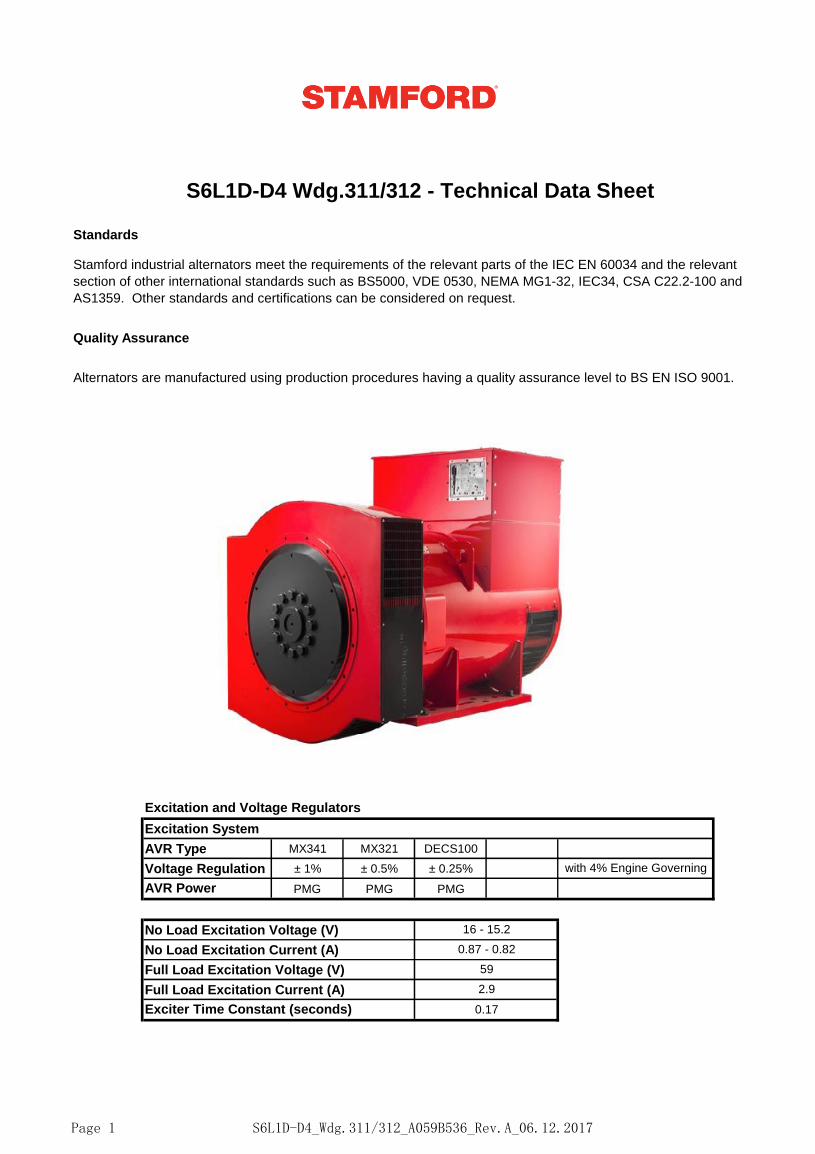
Standards
Quality Assurance
Excitation and Voltage Regulators
AVR Type MX341 MX321 DECS100
Voltage Regulation ± 1% ± 0.5% ± 0.25%
AVR Power PMG PMG PMG
Full Load Excitation Voltage (V) 59
Full Load Excitation Current (A) 2.9
Exciter Time Constant (seconds) 0.17
with 4% Engine Governing
No Load Excitation Voltage (V) 16 - 15.2
No Load Excitation Current (A) 0.87 - 0.82
S6L1D-D4 Wdg.311/312 - Technical Data Sheet
Stamford industrial alternators meet the requirements of the relevant parts of the IEC EN 60034 and the relevant
section of other international standards such as BS5000, VDE 0530, NEMA MG1-32, IEC34, CSA C22.2-100 and
AS1359. Other standards and certifications can be considered on request.
Excitation System
Alternators are manufactured using production procedures having a quality assurance level to BS EN ISO 9001.
Page 1 S6L1D-D4_Wdg.311/312_A059B536_Rev.A_06.12.2017
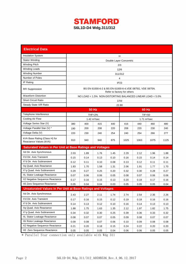
50 Hz 60 Hz
THF<2% TIF<50
1.42 m³/sec 1.71 m³/sec
380 400 415 440 416 440 460 480
190 200 208 220 208 220 230 240
220 230 240 254 240 254 266 277
910 940 940 875 1025 1063 1075 1125
Saturated Values in Per Unit at Base Ratings and Voltages
2.03 1.89 1.76 1.45 2.29 2.12 1.96 1.88
0.15 0.14 0.13 0.10 0.16 0.15 0.14 0.14
0.12 0.11 0.10 0.08 0.13 0.12 0.11 0.11
1.83 1.70 1.58 1.31 2.06 1.91 1.77 1.70
0.29 0.27 0.25 0.20 0.32 0.30 0.28 0.27
0.07 0.06 0.06 0.05 0.08 0.07 0.06 0.06
0.17 0.16 0.15 0.13 0.20 0.18 0.17 0.16
0.05 0.04 0.04 0.03 0.05 0.05 0.05 0.04
Unsaturated Values in Per Unit at Base Ratings and Voltages
2.43 2.27 2.11 1.74 2.74 2.54 2.35 2.26
0.17 0.16 0.15 0.12 0.19 0.18 0.16 0.16
0.14 0.13 0.12 0.10 0.16 0.14 0.13 0.13
1.88 1.75 1.63 1.35 2.12 1.97 1.82 1.75
0.34 0.32 0.30 0.25 0.39 0.36 0.33 0.32
0.08 0.07 0.07 0.05 0.09 0.08 0.07 0.07
0.09 0.08 0.07 0.06 0.10 0.09 0.08 0.08
0.21 0.20 0.18 0.15 0.24 0.22 0.20 0.20
0.05 0.05 0.05 0.04 0.06 0.06 0.05 0.05
* Parallel Star connection only available with Wdg 311
X'd Dir. Axis Transient
X''d Dir. Axis Subtransient
Xq Quad. Axis Reactance
X''q Quad. Axis Subtransient
XL Stator Leakage Reactance
Xlr Rotor Leakage Reactance
X2 Negative Sequence Reactance
X0 Zero Sequence Reactance
Xd Dir. Axis Synchronous
X''q Quad. Axis Subtransient
XL Stator Leakage Reactance
X2 Negative Sequence Reactance
X0 Zero Sequence Reactance
Xq Quad. Axis Reactance
Xd Dir. Axis Synchronous
X'd Dir. Axis Transient
X''d Dir. Axis Subtransient
Voltage Parallel Star (V) *
Voltage Delta (V)
Cooling Air Flow
Voltage Series Star (V)
kVA Base Rating (Class H) for
Reactance Values (kVA)
Telephone Interference
Number of Poles
Waveform Distortion
4
IP Rating IP23
RFI Suppression BS EN 61000-6-2 & BS EN 61000-6-4,VDE 0875G, VDE 0875N.
Refer to factory for others
NO LOAD < 1.5% NON-DISTORTING BALANCED LINEAR LOAD < 5.0%
Short Circuit Ratio 1/Xd
Steady State X/R Ratio 22.80
Winding Pitch 2/3
Winding Leads 12/6
Winding Number 311/312
S6L1D-D4 Wdg.311/312
Electrical Data
Insulation System H
Stator Winding Double Layer Concentric
Page 2 S6L1D-D4_Wdg.311/312_A059B536_Rev.A_06.12.2017
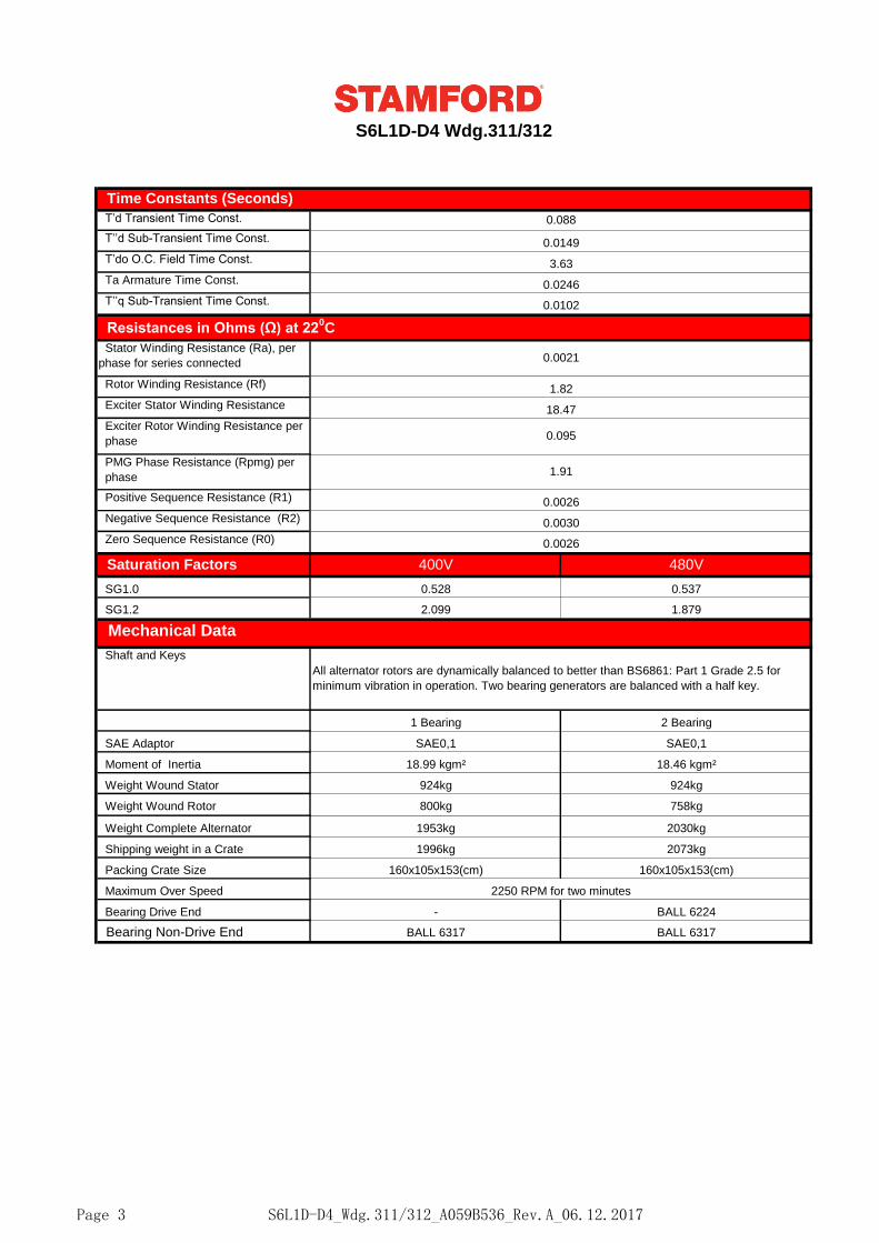
400V 480V
SG1.0 0.528 0.537
SG1.2 2.099 1.879
Packing Crate Size 160x105x153(cm) 160x105x153(cm)
Maximum Over Speed 2250 RPM for two minutes
Bearing Drive End - BALL 6224
Bearing Non-Drive End BALL 6317 BALL 6317
Shipping weight in a Crate 1996kg 2073kg
Weight Complete Alternator 1953kg 2030kg
Weight Wound Rotor 800kg 758kg
Moment of Inertia 18.99 kgm² 18.46 kgm²
Weight Wound Stator 924kg 924kg
1 Bearing 2 Bearing
SAE Adaptor SAE0,1 SAE0,1
Shaft and Keys
All alternator rotors are dynamically balanced to better than BS6861: Part 1 Grade 2.5 for
minimum vibration in operation. Two bearing generators are balanced with a half key.
Negative Sequence Resistance (R2) 0.0030
Zero Sequence Resistance (R0) 0.0026
Saturation Factors
Mechanical Data
Exciter Rotor Winding Resistance per
phase 0.095
PMG Phase Resistance (Rpmg) per
phase1.91
Positive Sequence Resistance (R1) 0.0026
Resistances in Ohms (Ω) at 220C
Stator Winding Resistance (Ra), per
phase for series connected 0.0021
Rotor Winding Resistance (Rf) 1.82
S6L1D-D4 Wdg.311/312
Time Constants (Seconds)
T’d Transient Time Const. 0.088
T’’d Sub-Transient Time Const. 0.0149
Exciter Stator Winding Resistance 18.47
T’do O.C. Field Time Const. 3.63
Ta Armature Time Const. 0.0246
T’’q Sub-Transient Time Const. 0.0102
Page 3 S6L1D-D4_Wdg.311/312_A059B536_Rev.A_06.12.2017
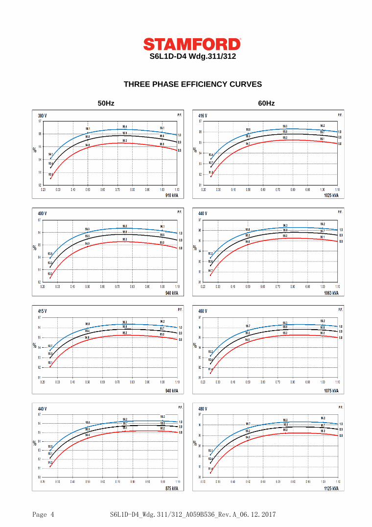
50Hz 60Hz
THREE PHASE EFFICIENCY CURVES
S6L1D-D4 Wdg.311/312
Page 4 S6L1D-D4_Wdg.311/312_A059B536_Rev.A_06.12.2017
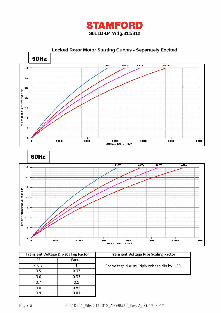
For voltage rise multiply voltage dip by 1.25
S6L1D-D4 Wdg.311/312
0.9 0.83
0.6 0.93
0.7 0.9
0.8 0.85
PF Factor
< 0.5 1
0.5 0.97
Locked Rotor Motor Starting Curves - Separately Excited
Transient Voltage Dip Scaling Factor
Locked Rotor Motor Starting Curves - Self Excited
Transient Voltage Rise Scaling Factor
50Hz
60Hz
Page 5 S6L1D-D4_Wdg.311/312_A059B536_Rev.A_06.12.2017
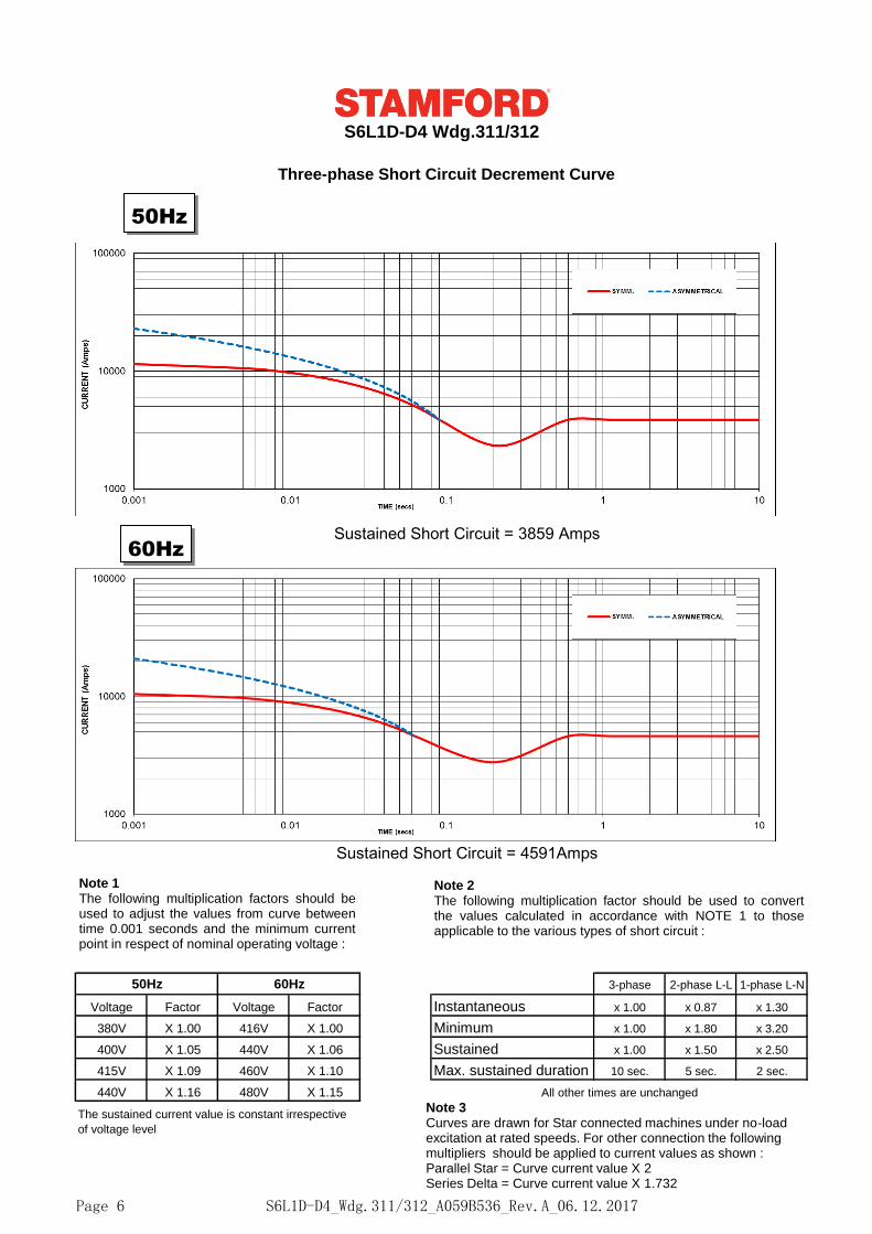
50Hz 60Hz 3-phase 2-phase L-L 1-phase L-N
Voltage Factor Voltage Factor Instantaneous x 1.00 x 0.87 x 1.30
380V X 1.00 416V X 1.00 Minimum x 1.00 x 1.80 x 3.20
400V X 1.05 440V X 1.06 Sustained x 1.00 x 1.50 x 2.50
415V X 1.09 460V X 1.10 Max. sustained duration 10 sec. 5 sec. 2 sec.
440V X 1.16 480V X 1.15
The sustained current value is constant irrespective
of voltage level
All other times are unchanged
S6L1D-D4 Wdg.311/312
Three-phase Short Circuit Decrement Curve
Sustained Short Circuit = 3859 Amps
Sustained Short Circuit = 4591Amps
Note 1The following multiplication factors should beused to adjust the values from curve betweentime 0.001 seconds and the minimum currentpoint in respect of nominal operating voltage :
Note 2The following multiplication factor should be used to convertthe values calculated in accordance with NOTE 1 to thoseapplicable to the various types of short circuit :
Note 3Curves are drawn for Star connected machines under no-load excitation at rated speeds. For other connection the following multipliers should be applied to current values as shown : Parallel Star = Curve current value X 2Series Delta = Curve current value X 1.732
50Hz
60Hz
S6L1D-D4_Wdg.311/312_A059B536_Rev.A_06.12.2017Page 6
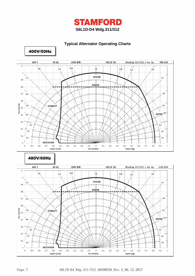
S6L1D-D4 Wdg.311/312
Typical Alternator Operating Charts
400V/50Hz
480V/60Hz
S6L1D-D4_Wdg.311/312_A059B536_Rev.A_06.12.2017Page 7
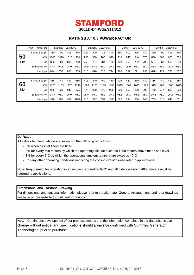
S6L1D-D4 Wdg.311/312
RATINGS AT 0.8 POWER FACTOR
Class - Temp Rise
Series Star (V) 380 400 415 440 380 400 415 440 380 400 415 440 380 400 415 440
kVA 1000 1010 1010 960 960 980 980 920 910 940 940 875 830 860 860 800
kW 800 808 808 768 768 784 784 736 728 752 752 700 664 688 688 640
Efficiency (%) 94.7 94.8 94.9 95.0 94.9 94.9 95.0 95.1 95.0 95.0 95.0 95.2 95.1 95.1 95.2 95.2
kW Input 844 852 851 808 810 826 826 774 766 792 791 736 698 723 723 672
Series Star (V) 416 440 460 480 416 440 460 480 416 440 460 480 416 440 460 480
kVA 1125 1163 1175 1219 1088 1125 1138 1188 1025 1063 1075 1125 915 965 1000 1025
kW 900 930 940 975 870 900 910 950 820 850 860 900 732 772 800 820
Efficiency (%) 94.9 95.0 95.0 95.0 95.0 95.0 95.1 95.1 95.1 95.1 95.2 95.2 95.2 95.2 95.2 95.2
kW Input 948 980 989 1026 916 947 957 1000 862 894 904 946 769 811 840 861
De-Rates
All values tabulated above are subject to the following reductions:
- 5% when air inlet filters are fitted
- 3% for every 500 meters by which the operating altitude exceeds 1000 meters above mean sea level
- 3% for every 5°C by which the operational ambient temperature exceeds 40°C
- For any other operating conditions impacting the cooling circuit please refer to applications
Note: Requirement for operating in an ambient exceeding 60°C and altitude exceeding 4000 meters must be
referred to applications.
Dimensional and Torsional Drawing
For dimensional and torsional information please refer to the alternator General Arrangement and rotor drawings
available on our website (http://stamford-avk.com/)
Note: Continuous development of our products means that the information contained in our data sheets can
change without notice, and specifications should always be confirmed with Cummins Generator
Technologies prior to purchase.
Standby - 163/27°C Standby - 150/40°C Cont. H - 125/40°C Cont. F - 105/40°C
50Hz
60Hz
S6L1D-D4_Wdg.311/312_A059B536_Rev.A_06.12.2017Page 8
Follow us @stamfordavk
Cummins Generator Technologies
View our videos at youtube.com/stamfordavk
news.stamford-avk.com
For Applications Support:
For Customer Service:
For General Enquiries:
Copyright 2016. Cummins Generator Technologies Ltd. All rights reserved.
Cummins and the Cummins logo are registered trade marks of Cummins Inc.
STAMFORD is a registered trade mark of Cummins Generator Technologies Ltd.
S6L1D-D4_Wdg.311/312_A059B536_Rev.A_06.12.2017Page 9