Embed Size (px)
DESCRIPTION
SA Roofing is the only publication in South Africa that is dedicated exclusively to the residential, commercial and industrial roofing and re-roofing industries.
Citation preview
AUGUST 2015 ISSUE: 72WWW.TRADEMAX.CO.ZA SA R36 EACH INCL. / R360 PER ANNUM INCL.

AUGUST 2015 ISSUE: 72
EDITOR’S COMMENTS ..................................................................................................... 2
CONTRIBUTORS ................................................................................................................ 7
EVENTS .................................................................................................................................. 8
COVER STORY............................................................................................................. 13-15
BUILDING MAINTENANCE ................................................................................... 16-17
OVER-ROOFING ......................................................................................................... 18-20
INDUSTRY NEWS ............................................................................................................ 22
ARCHITECTURAL INSIGHT ...................................................................................24-26
BUILDING WARRANTIES .......................................................................................28-31
ROOFING PHOTOGRAPHY ...................................................................................33-34
STEEL AWARDS 2015 ENTRIES ..............................................................................36-63
CEMENT & CONCRETE ................................................................................................. 66
3618
40
28
56
33
AUGUST 2015
13
Trademax Publications
SA Roofing
Tel: 0861 SA ROOF Tel: 0861 727 663 Fax: 0866 991 346
Email: [email protected]
www.trademax.co.za
Postnet Suite 241
Private Bag X103
N1 City
7463 PUBLISHER: Billy Perrin
082 266 6976
EDITOR: Tracy Swain
ADVERTISING: Jacqui Marsh
LAYOUT & DESIGN: Craig Patterson
SUBSCRIPTIONS: Belinda Thwesha
DISCLAIMERThe views expressed herein are not necessarily those of Trademax Publications. Although we have done our best to ensure the accuracy of our content, neither Trademax Publications nor SA Roofing magazine will be held liable for any views expressed or information disseminated, in
editorial content or advertisements, in this issue.
EDIT
OR
’S C
OM
MEN
TS
Every building material plays a vital role in the construction sector, but roundabout this time of the year, steel starts getting special attention as the build-up to the Steel
Awards begins and concludes with the winner announcements in September. This year is no different, and in our upcoming editions we will duly recognize steel. The industry is under strain at the moment, and all ears remain tuned to hear the stakeholders’ take on matters. SA Roofing is in talks with the spokespersons and will bring you that coverage as it is shared with us. For now, let’s enjoy and appreciate all that steel offers.
Something else on everyone’s mind is workplace safety. This, following the promulgation last year of the Construction Regulations 2014, which will come in to force now in August.
And rightfully so, especially for the roofing sector where so much work is performed at height. Firm steps need to be taken to accelerate the “Zero Harm” initiative and promote meaningful dialogue in all matters that impact occupational health and safety. Lives are at stake. Here at SA Roofing we are not roofers, we are storytellers. We love to share your accounts of great roofing projects, and we love to showcase your work.
But it is sometimes not possible to publish the photographs we receive, simply because the workmen are not pictured wearing the required safety gear. Apart from the necessity to ensure that everyone working at height does so safely, please help us bring you spectacular visuals by making sure that the photographs that accompany your stories, reflect the safety of the workmen. For good guidelines on what works, read the article on page 33.
Of course, there’s a lot more that we’re talking about this month – all in the pages following. Of particular note is the formation of TIPSASA, the new legal entity within the thermal insulation sector, covered on page 22.
I hope you enjoy the read. As always, feel free to drop me a line.
Hope to see you at the Cape Construction Expo!
Tracy
Xmas arriving in August?That’s what it feels like as I write this note. We just got totally spoilt, as SAISC’s Reneé Pretorius, editor of Steel Construction, kindly shared with us details of several Steel Awards 2015 entries. (Thank you!) They are all remarkable, and
we are so pleased to feature some of them in this issue of SA Roofing.
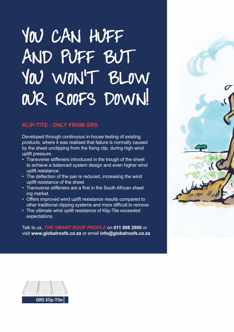
GRSGLOBAL ROOFING SOLUTIONSGRS Klip-Tite
KLIP-TITE - ONLY FROM GRS
Developed through continuous in-house testing of existing products, where it was realised that failure is normally caused by the sheet unclipping from the fi xing clip, during high wind uplift pressure.• Transverse stiffeners introduced in the trough of the sheet to achieve a balanced system design and even higher wind uplift resistance.• The defl ection of the pan is reduced, increasing the wind uplift resistance of the sheet.• Transverse stiffeners are a fi rst in the South African sheet ing market.• Offers improved wind uplift resistance results compared to other traditional clipping systems and more diffi cult to remove• The ultimate wind uplift resistance of Klip-Tite exceeded expectations
Talk to us, THE SMART ROOF PEOPLE on 011 898 2900 or visit www.globalroofs.co.za or email [email protected]
YOU CAN HUFF AND PUFF BUT YOU WON’T BLOWOUR ROOFS DOWN!
0224 GRS Wolfie DPS (297x420).indd 1 2015/01/15 1:30 PM
CONTACT: Tel: +27 11 814 1898 | Fax: +27 11 814 2166 | Email: [email protected] | Web: www.jcproofing.co.za
JCP Roofing is a new business that came into existence through JCP STEEL, a company that has been serving the steel industry with flat steel products for over 22 years, with a reputation for excellent service, uncompromising quality and impressive lead times.
We have expanded our portfolioto supply IBR and corrugatedroofing sheets to the same levelof quality and service to whichour customers areaccustomed to.
• IBR• Corrugated• Polycarbonate Sheeting• Bullnosing / Cranking• Flat Sheets• Screws & Fasteners
PRODUCTS:
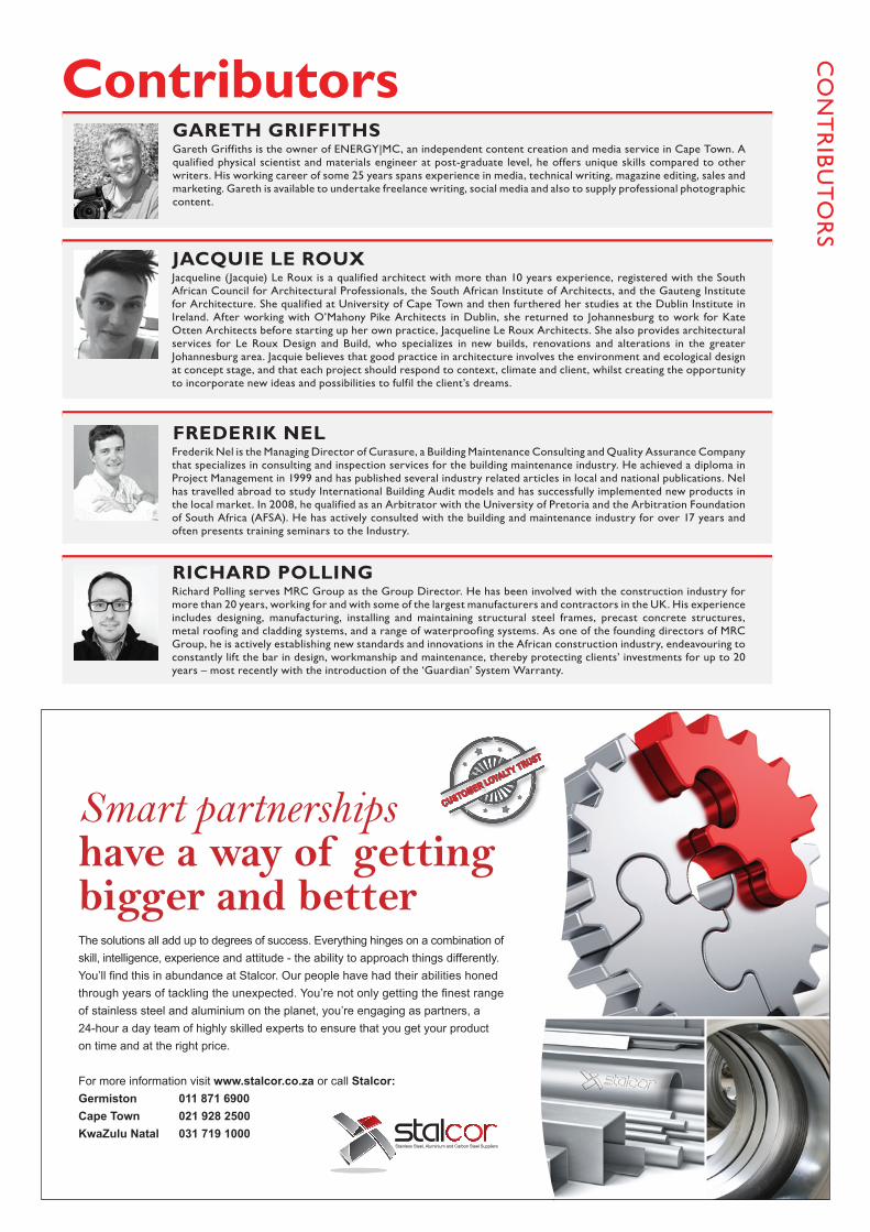
ContributorsGareth Griffiths is the owner of ENERGY|MC, an independent content creation and media service in Cape Town. A qualified physical scientist and materials engineer at post-graduate level, he offers unique skills compared to other writers. His working career of some 25 years spans experience in media, technical writing, magazine editing, sales and marketing. Gareth is available to undertake freelance writing, social media and also to supply professional photographic content.
Richard Polling serves MRC Group as the Group Director. He has been involved with the construction industry for more than 20 years, working for and with some of the largest manufacturers and contractors in the UK. His experience includes designing, manufacturing, installing and maintaining structural steel frames, precast concrete structures, metal roofing and cladding systems, and a range of waterproofing systems. As one of the founding directors of MRC Group, he is actively establishing new standards and innovations in the African construction industry, endeavouring to constantly lift the bar in design, workmanship and maintenance, thereby protecting clients’ investments for up to 20 years – most recently with the introduction of the ‘Guardian’ System Warranty.
Jacqueline (Jacquie) Le Roux is a qualified architect with more than 10 years experience, registered with the South African Council for Architectural Professionals, the South African Institute of Architects, and the Gauteng Institute for Architecture. She qualified at University of Cape Town and then furthered her studies at the Dublin Institute in Ireland. After working with O’Mahony Pike Architects in Dublin, she returned to Johannesburg to work for Kate Otten Architects before starting up her own practice, Jacqueline Le Roux Architects. She also provides architectural services for Le Roux Design and Build, who specializes in new builds, renovations and alterations in the greater Johannesburg area. Jacquie believes that good practice in architecture involves the environment and ecological design at concept stage, and that each project should respond to context, climate and client, whilst creating the opportunity to incorporate new ideas and possibilities to fulfil the client’s dreams.
GARETH GRIFFITHS
RICHARD POLLING
JACQUIE LE ROUX
CUSTOMER LOYALTY TRUST
CUSTOMER LOYALTY TRUST
The solutions all add up to degrees of success. Everything hinges on a combination of skill, intelligence, experience and attitude - the ability to approach things differently. You’ll fi nd this in abundance at Stalcor. Our people have had their abilities honed through years of tackling the unexpected. You’re not only getting the fi nest range of stainless steel and aluminium on the planet, you’re engaging as partners, a 24-hour a day team of highly skilled experts to ensure that you get your product on time and at the right price.
For more information visit www.stalcor.co.za or call Stalcor: Germiston 011 871 6900 Cape Town 021 928 2500 KwaZulu Natal 031 719 1000
Smart partnerships have a way of getting bigger and better
0334 Stalcor Partnership new 2015 (118x190).indd 1 2015/06/04 9:19 AM
CO
NT
RIB
UT
OR
S
Frederik Nel is the Managing Director of Curasure, a Building Maintenance Consulting and Quality Assurance Company that specializes in consulting and inspection services for the building maintenance industry. He achieved a diploma in Project Management in 1999 and has published several industry related articles in local and national publications. Nel has travelled abroad to study International Building Audit models and has successfully implemented new products in the local market. In 2008, he qualified as an Arbitrator with the University of Pretoria and the Arbitration Foundation of South Africa (AFSA). He has actively consulted with the building and maintenance industry for over 17 years and often presents training seminars to the Industry.
FREDERIK NEL
EVEN
TS Upcoming Events
WOODEX FOR AFRICA 9-11 JUNE 2016, GALLAGHER CONVENTION CENTRE, JOHANNESBURG
View www.woodexforafrica.com for more info
CAPE CONSTRUCTION CONFERENCE & TRADE EXPO 12 & 13 AUGUST 2015, CTICC, CAPE TOWN
View www.cape-construction.co.za for more info
110TH ANNUAL MBSA CONGRESS 16 & 17 SEPTEMBER 2015, JOHANNESBURG EXPO CENTRE
View www.masterbuilderscongress.co.za for more info
The Cape Construction Conference & Trade Expo is centred around the building and construction industry in the Western Cape. The forum covers the entire value chain and targets small, medium and large enterprises. The event features a 2-day strategic conference, an interactive exhibition with the latest products, tools and technologies, as well as a workshop training programme that includes commercial and DIY content. With 2500+ attendees, 25 expert speakers, 80+ exhibiting companies and 10 free-to-attend workshops, the Cape Construction Conference & Trade Expo is the must-attend event for construction professionals.
CALL 0861 727 663 TO BOOK YOUR
CLASSIFIED ADVERT
Reg No: CoR18.3 2013/068719/07 VAT No: 4930188372
QUALITY FASTENING SYSTEMSMANUFACTURERS OF
JHB Branch: Contact: Tanny | Tel: 011 - 979 5026/7 | Cell: 082 782 6854 | P.O. Box 14353, Bredell, Kempton Park
Manufactured in Taiwan
DBN Branch: Contact: Summers | Tel/Fax: 031 - 765 1604 | Cell: 082 564 1463 | [email protected]
www.hengfuscrews.co.za
AUGUST 20158
-
Cnr Berkley and Bax Roads, Maitland 7405
AUTHORIZED DISTRIBUTOROF LAMBDABOARD AND MODEK TRANSLUCENT SHEETING
New Youngman premises:Architecture by Martin Commerford of DHA and interiors by Leon Saven Design

BOOKNOW!
EXPLORENEW BUSINESS
OPPORTUNITIESAT AFRICA’S ONLY TIMBER MACHINERY, TOOLING, MATERIALS & FITTINGS EXHIBITION
9-11JUNE2016
Gallagher Convention Centre | Midrand | South [email protected] | +27 (0) 21 856 4334
www.woodexforafrica.com
Furniture & Kitchen production | Forestry & Sawmilling | Wood Materials, Machinery & Veneers Tools, Loggers & mobile Saws | Timber Construction and supply | Industry Surface & Treatment Technologies
Many more Timber related products, machinery and services.


NINEFIVENINEDC@2015
Those who hold tomorrow,count on our green choices today.
We choose a brighter future for them. Do you?
Pioneering a sustainable roofing alternative with the Chromadek roofing range, using a chrome free colour coating process. This is beneficial to both the immediate environment as well as positively impacting on the ecological balance as a whole.
www.arcelormittalsa.com
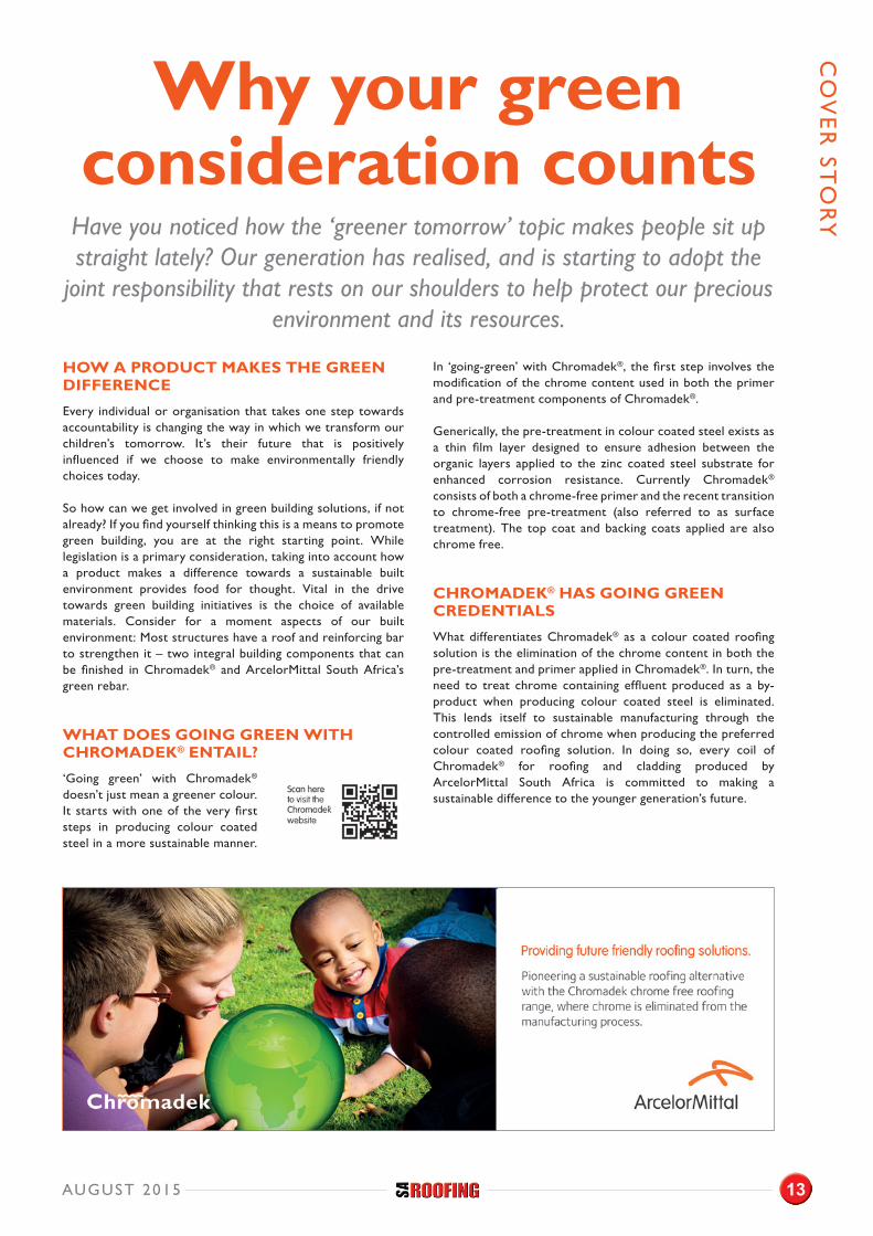
HOW A PRODUCT MAKES THE GREEN DIFFERENCE
Every individual or organisation that takes one step towards accountability is changing the way in which we transform our children’s tomorrow. It’s their future that is positively influenced if we choose to make environmentally friendly choices today.
So how can we get involved in green building solutions, if not already? If you find yourself thinking this is a means to promote green building, you are at the right starting point. While legislation is a primary consideration, taking into account how a product makes a difference towards a sustainable built environment provides food for thought. Vital in the drive towards green building initiatives is the choice of available materials. Consider for a moment aspects of our built environment: Most structures have a roof and reinforcing bar to strengthen it – two integral building components that can be finished in Chromadek® and ArcelorMittal South Africa’s green rebar.
WHAT DOES GOING GREEN WITH CHROMADEK® ENTAIL?
‘Going green’ with Chromadek® doesn’t just mean a greener colour. It starts with one of the very first steps in producing colour coated steel in a more sustainable manner.
In ‘going-green’ with Chromadek®, the first step involves the modification of the chrome content used in both the primer and pre-treatment components of Chromadek®.
Generically, the pre-treatment in colour coated steel exists as a thin film layer designed to ensure adhesion between the organic layers applied to the zinc coated steel substrate for enhanced corrosion resistance. Currently Chromadek® consists of both a chrome-free primer and the recent transition to chrome-free pre-treatment (also referred to as surface treatment). The top coat and backing coats applied are also chrome free.
CHROMADEK® HAS GOING GREEN CREDENTIALS
What differentiates Chromadek® as a colour coated roofing solution is the elimination of the chrome content in both the pre-treatment and primer applied in Chromadek®. In turn, the need to treat chrome containing effluent produced as a by-product when producing colour coated steel is eliminated. This lends itself to sustainable manufacturing through the controlled emission of chrome when producing the preferred colour coated roofing solution. In doing so, every coil of Chromadek® for roofing and cladding produced by ArcelorMittal South Africa is committed to making a sustainable difference to the younger generation’s future.
Why your green consideration counts
Have you noticed how the ‘greener tomorrow’ topic makes people sit up straight lately? Our generation has realised, and is starting to adopt the
joint responsibility that rests on our shoulders to help protect our precious environment and its resources.
CO
VE
R ST
OR
Y
AUGUST 2015 13
NINEFIVENINEDC@2015
Those who hold tomorrow,count on our green choices today.
We choose a brighter future for them. Do you?
Pioneering a sustainable roofing alternative with the Chromadek roofing range, using a chrome free colour coating process. This is beneficial to both the immediate environment as well as positively impacting on the ecological balance as a whole.
www.arcelormittalsa.com
CO
VE
R S
TO
RY
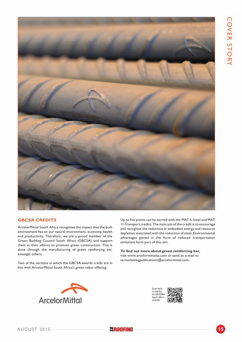
GREEN REBAR
ArcelorMittal South Africa is introducing a range of green-reinforcing products that provides a more sustainable use of materials in structures. The essential difference between traditional reinforcing bar and green reinforcing bar is the input material scrap percentage.
The input material for rebar, as we know it, consists of 5% to 15% scrap, whereas green rebar has a minimum post-consumer recycled scrap percentage of 90%. Once a finished product has served its intended use and has been diverted or recovered from waste destined for disposal, it is then considered ‘post-consumer scrap.’
ArcelorMittal Vereeniging Works is South Africa’s largest steel recycler and fully supports the more environmental friendly production process. The Electric Arc Furnace (EAF) has outstanding capabilities in managing scrap consumption when producing green steel.
Various environmental benefits greatly distinguish green reinforcing bar from traditional reinforcing steels. It provides contractors, developers and end users in construction with an environmentally friendly building material. ArcelorMittal South Africa is committed to manufacturing and rolling green rebar using the most economic methods.
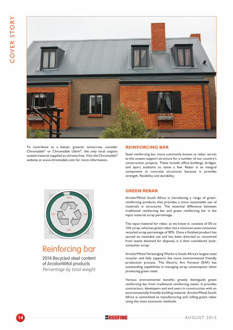
To contribute to a better, greener tomorrow, consider Chromadek® or Chromadek Ultim®, the only local organic coated material supplied as chrome free. Visit the Chromadek® website at www.chromadek.com for more information.
REINFORCING BAR
Steel reinforcing bar, more commonly known as rebar, serves as the unseen support structure for a number of our country’s construction projects. These include office buildings, bridges, and sport stadiums to name a few. Rebar is an integral component in concrete structures because it provides strength, flexibility and durability.
AUGUST 201514
CO
VE
R ST
OR
Y
GBCSA CREDITS
ArcelorMittal South Africa recognises the impact that the built environment has on our natural environment, economy, health and productivity. Therefore, we are a proud member of the Green Building Council South Africa (GBCSA) and support them in their efforts to promote green construction. This is done through the manufacturing of green reinforcing bar, amongst others.
Two of the sections in which the GBCSA awards credit are in line with ArcelorMittal South Africa’s green rebar offering.
Up to five points can be earned with the MAT 6-Steel and MAT 11-Transport credits. The main aim of the credit is to encourage and recognise the reduction in embodied energy and resource depletion associated with the reduction of steel. Environmental advantages gained in the form of reduced transportation emissions form part of this aim.
To find out more about green reinforcing bar, visit www.arcelormittalsa.com or send an e-mail to [email protected].
AUGUST 2015 15
BU
ILD
ING
MA
INT
EN
AN
CE
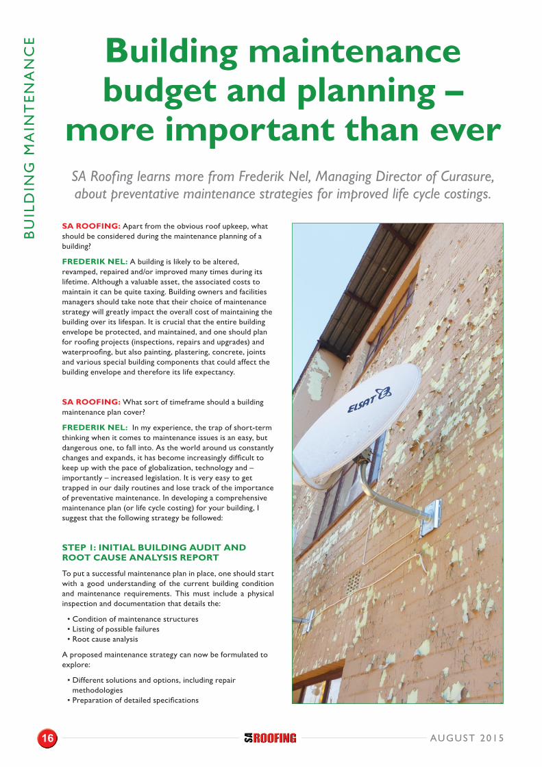
SA ROOFING: Apart from the obvious roof upkeep, what should be considered during the maintenance planning of a building?
FREDERIK NEL: A building is likely to be altered, revamped, repaired and/or improved many times during its lifetime. Although a valuable asset, the associated costs to maintain it can be quite taxing. Building owners and facilities managers should take note that their choice of maintenance strategy will greatly impact the overall cost of maintaining the building over its lifespan. It is crucial that the entire building envelope be protected, and maintained, and one should plan for roofing projects (inspections, repairs and upgrades) and waterproofing, but also painting, plastering, concrete, joints and various special building components that could affect the building envelope and therefore its life expectancy.
SA ROOFING: What sort of timeframe should a building maintenance plan cover?
FREDERIK NEL: In my experience, the trap of short-term thinking when it comes to maintenance issues is an easy, but dangerous one, to fall into. As the world around us constantly changes and expands, it has become increasingly difficult to keep up with the pace of globalization, technology and – importantly – increased legislation. It is very easy to get trapped in our daily routines and lose track of the importance of preventative maintenance. In developing a comprehensive maintenance plan (or life cycle costing) for your building, I suggest that the following strategy be followed:
STEP 1: INITIAL BUILDING AUDIT AND ROOT CAUSE ANALYSIS REPORT
To put a successful maintenance plan in place, one should start with a good understanding of the current building condition and maintenance requirements. This must include a physical inspection and documentation that details the:
• Condition of maintenance structures• Listing of possible failures• Root cause analysis
A proposed maintenance strategy can now be formulated to explore:
• Different solutions and options, including repair methodologies
• Preparation of detailed specifications
Building maintenance budget and planning –
more important than everSA Roofing learns more from Frederik Nel, Managing Director of Curasure, about preventative maintenance strategies for improved life cycle costings.
AUGUST 201516
STEP 2: TENDER PROCESS
In facilitating a transparent tender process to obtain market related prices, it is important to record the process diligently.
• Formulate a detailed ‘Scope of Work’ document, based on the initial audit
• Include detailed specifications for each substrate for pricing
• Obtain a list of approved applicators or service providers for pricing the work
• Hold physical tender meetings on site to ensure that all parties are informed
• Create a ‘Set Scope and Tender Document’ for price comparisons
STEP 3: PROJECT PHASE AND QUALITY CONTROL
As the saying goes, “The best guarantee we have, is ensuring the job is done right, the first time.”
• Prepare and conclude detailed contracts for the project phase
• Appoint Quality Control Agents to ensure that maintenance work is carried out to specifications
• Track progress through regular update reports• Finalize the close-out procedures and documentation
STEP 4: MAINTENANCE BUDGETS AND PLANNING
Upon completion of a project, it is important to revisit the ‘Initial Building Audit Report’ and plan for additional projects and, most importantly, to plan for preventative cycles. This can be achieved through:
• Regularly updating the Building Audit Report• Forward planning and life cycle costing for each building
component• Development of a maintenance budget• Making sure that maintenance plans for future maintenance
include:• Major maintenance cycles• Interim or preventative cycles
It is recommended that building owners update their maintenance strategies and budgets on a yearly basis. Building owners should also consider employing specialist consulting companies to assist with long-term maintenance planning. The benefit is real and will have a significant impact on the maintenance expenditure during the lifespan of maintenance cycles.
My advice to property owners: Plan well in advance and implement short-, medium- and long-term maintenance strategies.
For more information, email Frederik Nel at [email protected] or visit www.curasure.co.za.
BU
ILDIN
G M
AIN
TE
NA
NC
E
Curasure offers Independent, Third Party Building Maintenance Solutions for Commercial Property Owners, Bodies Corporate, and the Maintenance Industry as a whole.
WE SPECIALISE IN:
OUR SERVICES INCLUDE:
“ …IS YOUR MAINTENANCE PROJECT A QUALITY ASSURED PROJECT… ”
The advantages of having an Independent Building Envelope Professional and Quality Control company employed is almost immeasurable, and will give Property Owners peace of mind when it comes to maintenance projects and planning requirements.
Identifying Maintenance Requirements
Technical Assessments Report for Buildings
Developing and Specifying of Solutions
Quality Assurance during Maintenance Projects
On-going & Preventative Maintenance Planning, Systems and Strategies
www.curasure.co.za [email protected] 011 675 2595
Copyright © Curasure 2015
Building Audit Reports(Detailed technical building assessment reports with recommendations, maintenance strategies & technical specifications)
Tender Process((Facilitating of a Third Party Tender process by compiling the complete tender pack with scope of work and specifications. We also provide a full tender evaluation on completion)
Quality Assurance(On-site Third Party Quality Control & Certification for Maintenance Projects)
On-going and Long-Term Maintenance Management ((Sinking fund reports with 5-10 year maintenance forecasts and systems)
Turnkey Maintenance Systems(Short, Medium and Long-Term Maintenance Management of Building Structures)
OV
ER
-RO
OFI
NG
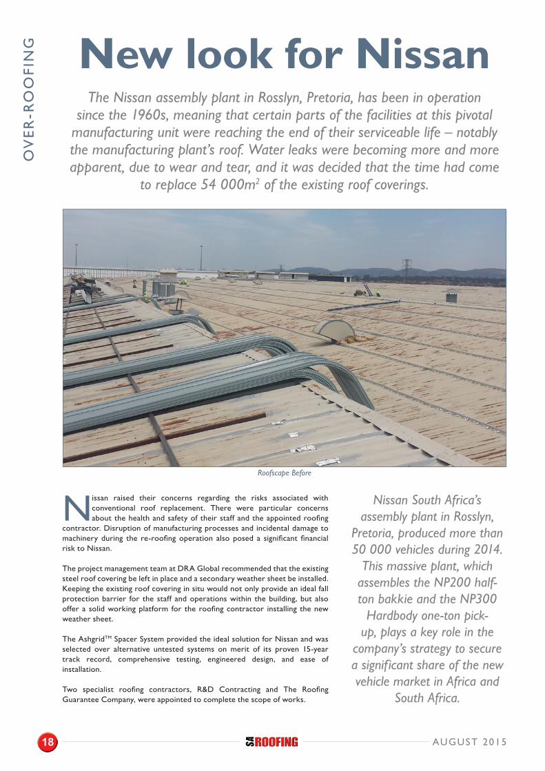
Nissan raised their concerns regarding the risks associated with conventional roof replacement. There were particular concerns about the health and safety of their staff and the appointed roofing
contractor. Disruption of manufacturing processes and incidental damage to machinery during the re-roofing operation also posed a significant financial risk to Nissan.
The project management team at DRA Global recommended that the existing steel roof covering be left in place and a secondary weather sheet be installed. Keeping the existing roof covering in situ would not only provide an ideal fall protection barrier for the staff and operations within the building, but also offer a solid working platform for the roofing contractor installing the new weather sheet.
The AshgridTM Spacer System provided the ideal solution for Nissan and was selected over alternative untested systems on merit of its proven 15-year track record, comprehensive testing, engineered design, and ease of installation.
Two specialist roofing contractors, R&D Contracting and The Roofing Guarantee Company, were appointed to complete the scope of works.
New look for NissanThe Nissan assembly plant in Rosslyn, Pretoria, has been in operation
since the 1960s, meaning that certain parts of the facilities at this pivotal manufacturing unit were reaching the end of their serviceable life – notably the manufacturing plant’s roof. Water leaks were becoming more and more apparent, due to wear and tear, and it was decided that the time had come
to replace 54 000m2 of the existing roof coverings.
Nissan South Africa’s assembly plant in Rosslyn,
Pretoria, produced more than 50 000 vehicles during 2014.
This massive plant, which assembles the NP200 half-ton bakkie and the NP300
Hardbody one-ton pick-up, plays a key role in the
company’s strategy to secure a significant share of the new vehicle market in Africa and
South Africa.
Roofscape Before
AUGUST 201518
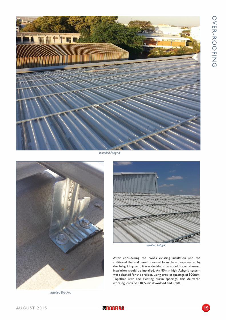
After considering the roof’s existing insulation and the additional thermal benefit derived from the air gap created by the Ashgrid system, it was decided that no additional thermal insulation would be installed. An 85mm high Ashgrid system was selected for the project, using bracket spacings of 500mm. Together with the existing purlin spacings, this delivered working loads of 3.0kN/m2 download and uplift.
OV
ER
-RO
OFIN
G
Installed Bracket
Installed Ashgrid
Installed Ashgrid
AUGUST 2015 19
OV
ER
-RO
OFI
NG
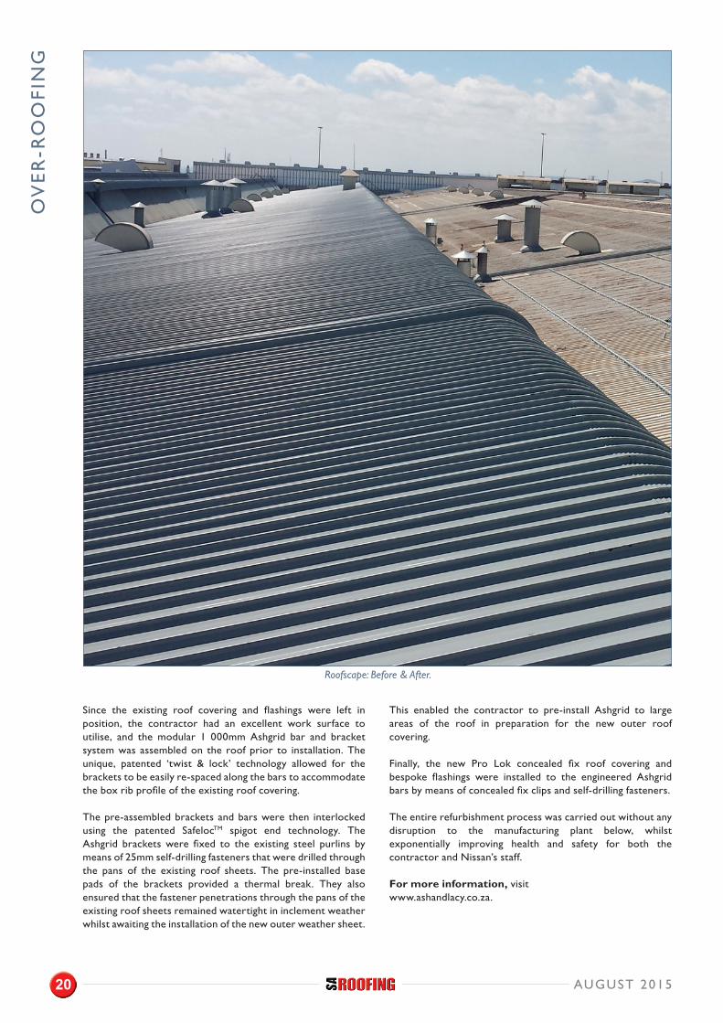
Since the existing roof covering and flashings were left in position, the contractor had an excellent work surface to utilise, and the modular 1 000mm Ashgrid bar and bracket system was assembled on the roof prior to installation. The unique, patented ‘twist & lock’ technology allowed for the brackets to be easily re-spaced along the bars to accommodate the box rib profile of the existing roof covering.
The pre-assembled brackets and bars were then interlocked using the patented SafelocTM spigot end technology. The Ashgrid brackets were fixed to the existing steel purlins by means of 25mm self-drilling fasteners that were drilled through the pans of the existing roof sheets. The pre-installed base pads of the brackets provided a thermal break. They also ensured that the fastener penetrations through the pans of the existing roof sheets remained watertight in inclement weather whilst awaiting the installation of the new outer weather sheet.
This enabled the contractor to pre-install Ashgrid to large areas of the roof in preparation for the new outer roof covering.
Finally, the new Pro Lok concealed fix roof covering and bespoke flashings were installed to the engineered Ashgrid bars by means of concealed fix clips and self-drilling fasteners.
The entire refurbishment process was carried out without any disruption to the manufacturing plant below, whilst exponentially improving health and safety for both the contractor and Nissan’s staff.
For more information, visit www.ashandlacy.co.za.
Roofscape: Before & After.
AUGUST 201520
M: +27+83 215 1782
O: +27+21+782 0255
Ash & Lacy Building Systems
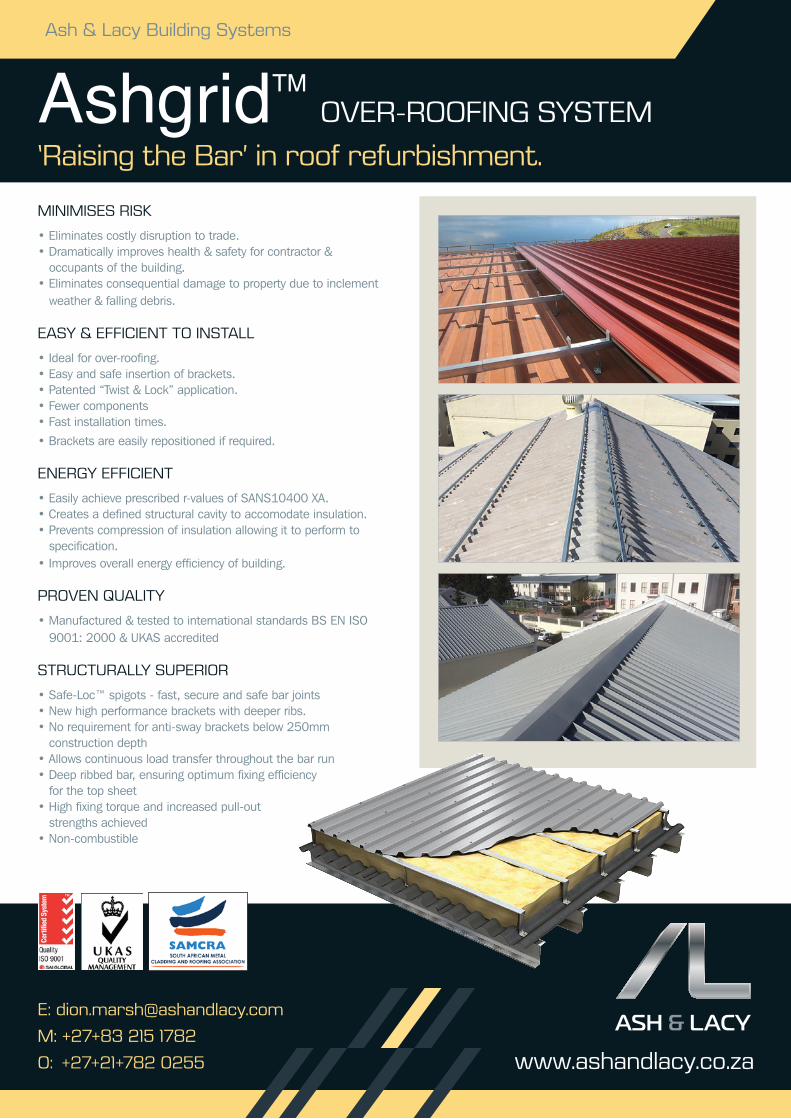
AshgridTM
www.ashandlacy.co.za
‘Raising the Bar’ in roof refurbishment.
OvER-ROOfing SyStEM
MiniMiSES RiSK
• Eliminates costly disruption to trade.• Dramatically improves health & safety for contractor &
occupants of the building.• Eliminates consequential damage to property due to inclement
weather & falling debris.
EASy & EffiCiEnt tO inStALL
• Ideal for over-roofing.• Easy and safe insertion of brackets.• Patented “Twist & Lock” application.• Fewer components • Fast installation times.
• Brackets are easily repositioned if required.
EnERgy EffiCiEnt
• Easily achieve prescribed r-values of SANS10400 XA.• Creates a defined structural cavity to accomodate insulation.• Prevents compression of insulation allowing it to perform to
specification.• Improves overall energy efficiency of building.
PROvEn QUALity
• Manufactured & tested to international standards BS EN ISO 9001: 2000 & UKAS accredited
StRUCtURALLy SUPERiOR
• Safe-Loc™ spigots - fast, secure and safe bar joints• New high performance brackets with deeper ribs.• No requirement for anti-sway brackets below 250mm
construction depth• Allows continuous load transfer throughout the bar run• Deep ribbed bar, ensuring optimum fixing efficiency
for the top sheet• High fixing torque and increased pull-out
strengths achieved• Non-combustible
8895 - A4 SA advert.indd 1 19/06/2015 11:14
IND
UST
RY
NE
WS
This move will enable the Association to open its doors to other energy-efficient products and systems in the thermal insulation industry not previously
accommodated, such as wall systems, exterior wall systems, and barrier wall systems for multiple applications, etc.
The current Board Members of TIASA, the stalwarts of the thermal insulation industry in South Africa, will serve as the new Directors of TIPSASA. They are: Ms Lisa Reynolds (Saint-Gobain), Mr Alf Peyper (Insulation Convertors and Distributors), Mr Lammie de Beer (Technopol SA), Mr Gary Rowley (Vedder & Moffat), Mr Grant Richardson (Granric Insulation), and Mr Gary Sweeney (Spunchem International).
Ms Des Schnetler and Mr Grant Richardson have been re-elected as Chairperson and Vice-Chairman of TIASA respectively and will also serve in this capacity at TIPSASA.
The Chairperson, Des Schnetler, said, “I am very happy to be able to welcome our new board members. Their knowledge and experience will undoubtedly add to an Association that is already strong and rich in talents. Their combined experience and valuable insights, into a number of fields, will be beneficial to the Association and will help us to address the energy efficiency challenges facing the country in the coming years.”
WHAT DOES THE FUTURE HOLD FOR TIPSASA?
Energy efficiency is one of the most pressing concerns for today's property owners, and with good reason. Energy costs are rising with no end in sight, and we are all looking at ways to reduce energy bills.
The Energy Efficiency Regulations were promulgated in September 2011, applicable to new buildings and extensions. We should now concentrate on existing building stock by retrofitting (adding insulation on top of the ceilings). In many existing buildings, the roof and ceilings are often not insulated properly or not insulated at all. Many people fail to realise that a building system can have a huge impact on a building's energy efficiency. The building envelope plays a critical role, as it forms the barrier between a building's interior and exterior environments.
A well-insulated and/or well-designed building will provide year-round comfort, cutting cooling and heating costs and reducing greenhouse emissions.
The Association is also now affiliated with the Southern African Association for Energy Efficiency (SAEE). Skills development is also high on the priority list as the best insulation can be ruined if not correctly installed. Training on the installation of thermal insulation is essential to ensure that materials are correctly installed. Not only will it ensure that materials are correctly installed, but this will create business opportunities for entrepreneurs to start their own small businesses once trained. In the interim, there are existing contractors who are both members of the Association and accredited installers.
For more information, please contact TIPSASA on 0861 000 334 or 082 305 8559 (cellular), or email [email protected].
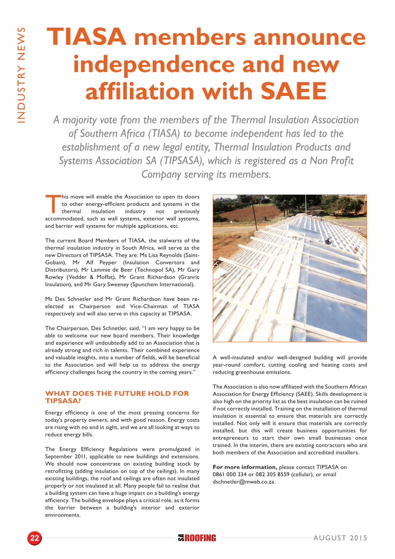
TIASA members announce independence and new affiliation with SAEE
A majority vote from the members of the Thermal Insulation Association of Southern Africa (TIASA) to become independent has led to the
establishment of a new legal entity, Thermal Insulation Products and Systems Association SA (TIPSASA), which is registered as a Non Profit
Company serving its members.
AUGUST 201522

Administered by
By adding just 1% to your total building cost, you can install state of the art insulation.
The result: • comfortable surroundings • saving money on energy costs • supporting a sustainable environment
Insulation -The invisible energy saver
Contact our members for products and services that meet the requirements of quality, performance and safety as set by the Thermal Insulation Association of Southern Africa (TIASA).
For a comprehensive list of Insulation Contractors, Distributors, Manufacturers, Suppliers & Specialists please visit: www.tiasa.org.za Office: (011) 805 5002.
CORPORATE MEMBERS
™
AR
CH
ITEC
TU
RA
L IN
SIG
HT
While good architecture has always considered the environment and the impact of buildings on their surroundings as well as their inhabitants, the
pressure of diminishing resources and the soaring costs of building and, more importantly, maintaining the building for its lifespan, now require that the building responds to these factors more stringently. Every scale of building development, from domestic to commercial to large-scale plants, is increasingly responding to the necessity for design that creates optimal energy consumption and is flexible enough to respond to a looming future with limited water, no electricity, and an increasing reliance on computers and the Internet for connectivity.
CHALLENGES
A building is an expensive piece of hardware, and developers and clients are becoming more inclined to look carefully at its design and long-term flexibility and maintenance requirements than before.
The challenge is to change not just the design industry, but also the construction industry in a country dependent on labour-intensive building techniques. The use of new technologies is slow to catch on. Green building techniques and materials are often seen as expensive and untested, and the public is reluctant to use the unknown.
Adapting design – an architect’s perspective Facing limited resources, architects, clients and developers are rising to
the challenge; the building industry is responding to the growing concerns around the rising costs and growing scarcity of energy and water supplies.
Article by Jacquie Le Roux, architect and member of SACAP and GIFA.
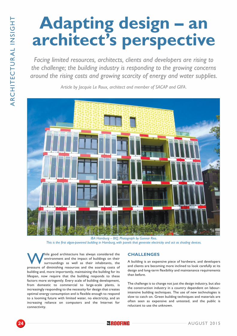
IBA Hamburg – BIQ. Photograph by Gunnar Ries. This is the first algae-powered building in Hamburg, with panels that generate electricity and act as shading devices.
AUGUST 201524
AR
CH
ITEC
TU
RA
L IN
SIG
HT
THE LAW. AND THE CONSUMER.
However, South Africa has signed the Kyoto Protocol, and we now have legislation in place controlling energy and water usage. Built environment professionals have to understand and implement the law. The end result of the implementation of the law should be sustainable buildings that are cost effective. Although South Africans do not generally have a good track record of enforcing implementation, the cost implications of energy efficiency are assisting in making the ‘greening’ of the building attractive to developers, as they are also cost-effective buildings.
Of the three ways to comply with the law, XA3 is the most interesting as it allows for a designer to submit a rational design, opening up new possibilities. We all know the basics about energy efficiency in buildings, and the new energy conservation that has become everyday practice, but a good example of the general public’s grasp of the basics is the proposed implementation of solar panels for the whole neighbourhood by the Parkhurst Residents Association (in Gauteng). As an example of mass action, this allows for the most important element of maintenance to be built into the contract of supply and install, and demonstrates how communities are responding not only to the ideal of a greener environment, but also the rising costs and interrupted supply of electricity.
GREENING POSSIBILITIES
The most interesting outcomes of the enforced greening, both legally and financially, of our building industry, are the various possibilities for the future. Research into energy and water saving techniques is producing amazing concepts, which are starting to become realities. The Department of Bio-Chemistry at the University of Cambridge is developing ways of using moss and algae to generate electricity – a biological solar panel. This means that your green wall of plants and moss could actually contribute to your insulation and to your electricity.
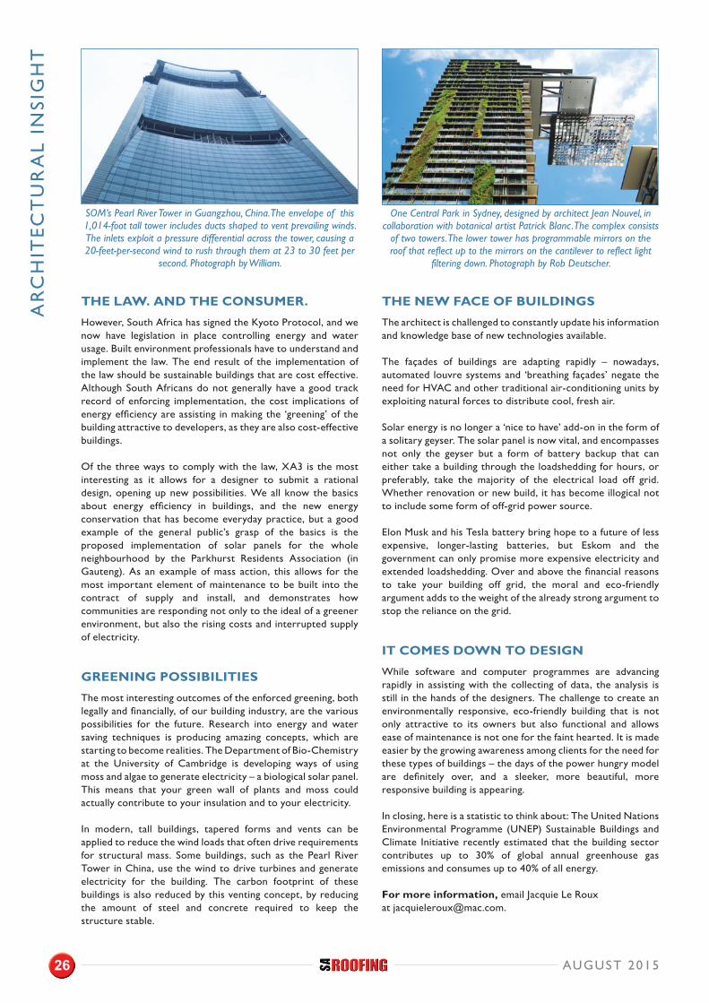
In modern, tall buildings, tapered forms and vents can be applied to reduce the wind loads that often drive requirements for structural mass. Some buildings, such as the Pearl River Tower in China, use the wind to drive turbines and generate electricity for the building. The carbon footprint of these buildings is also reduced by this venting concept, by reducing the amount of steel and concrete required to keep the structure stable.
THE NEW FACE OF BUILDINGS
The architect is challenged to constantly update his information and knowledge base of new technologies available.
The façades of buildings are adapting rapidly – nowadays, automated louvre systems and ‘breathing façades’ negate the need for HVAC and other traditional air-conditioning units by exploiting natural forces to distribute cool, fresh air.
Solar energy is no longer a ‘nice to have’ add-on in the form of a solitary geyser. The solar panel is now vital, and encompasses not only the geyser but a form of battery backup that can either take a building through the loadshedding for hours, or preferably, take the majority of the electrical load off grid. Whether renovation or new build, it has become illogical not to include some form of off-grid power source.
Elon Musk and his Tesla battery bring hope to a future of less expensive, longer-lasting batteries, but Eskom and the government can only promise more expensive electricity and extended loadshedding. Over and above the financial reasons to take your building off grid, the moral and eco-friendly argument adds to the weight of the already strong argument to stop the reliance on the grid.
IT COMES DOWN TO DESIGN
While software and computer programmes are advancing rapidly in assisting with the collecting of data, the analysis is still in the hands of the designers. The challenge to create an environmentally responsive, eco-friendly building that is not only attractive to its owners but also functional and allows ease of maintenance is not one for the faint hearted. It is made easier by the growing awareness among clients for the need for these types of buildings – the days of the power hungry model are definitely over, and a sleeker, more beautiful, more responsive building is appearing.
In closing, here is a statistic to think about: The United Nations Environmental Programme (UNEP) Sustainable Buildings and Climate Initiative recently estimated that the building sector contributes up to 30% of global annual greenhouse gas emissions and consumes up to 40% of all energy.
For more information, email Jacquie Le Roux at [email protected].
SOM’s Pearl River Tower in Guangzhou, China. The envelope of this 1,014-foot tall tower includes ducts shaped to vent prevailing winds. The inlets exploit a pressure differential across the tower, causing a 20-feet-per-second wind to rush through them at 23 to 30 feet per
second. Photograph by William.
One Central Park in Sydney, designed by architect Jean Nouvel, in collaboration with botanical artist Patrick Blanc. The complex consists
of two towers. The lower tower has programmable mirrors on the roof that reflect up to the mirrors on the cantilever to reflect light
filtering down. Photograph by Rob Deutscher.
AUGUST 201526

BU
ILD
ING
WA
RR
AN
TIE
S
THE PROBLEM WITH MATERIAL GUARANTEES AND WORKMANSHIP WARRANTIES
Guarantees and warranties are a key part of any building envelope system. The individual manufacturers of the building envelope each provide a material guarantee, and the ‘approved’ contactor who undertakes installation, offers a workmanship warranty. In most cases, the material guarantee terms extend beyond the term of the workmanship warranty.
In modern building construction, a large range of differing materials and systems are used to construct the building envelope. Each of the installed systems will be supplied with its own individual guarantees and associated small print to be found in the T’s and C’s, leaving the client, being the property owner (developer or building owner), to manage the risk of these individual parts that make up the building envelope.
MANY OF THE GUARANTEES AND WARRANTIES OFFERED DO NOT COVER IMPORTANT AREAS SUCH AS:
1. The material guarantee matching the term of the workmanship warranty.
2. Perimeter detailing and construction.3. Junction points between dissimilar materials.4. Water ponding and debris build up.5. Thermal, structural and acoustic performance.6. Installation of associated building envelope technologies
such as solar panels, walkways and fall arrest systems.
Most manufacturers are not able to cover the important workmanship or the ongoing maintenance of the building envelope. This creates a weak link in the construction supply chain, because most problems that occur are usually as a direct result of bad design, poor workmanship, and a lack of understanding of dissimilar material junctions that lead to leaks within the building envelope.
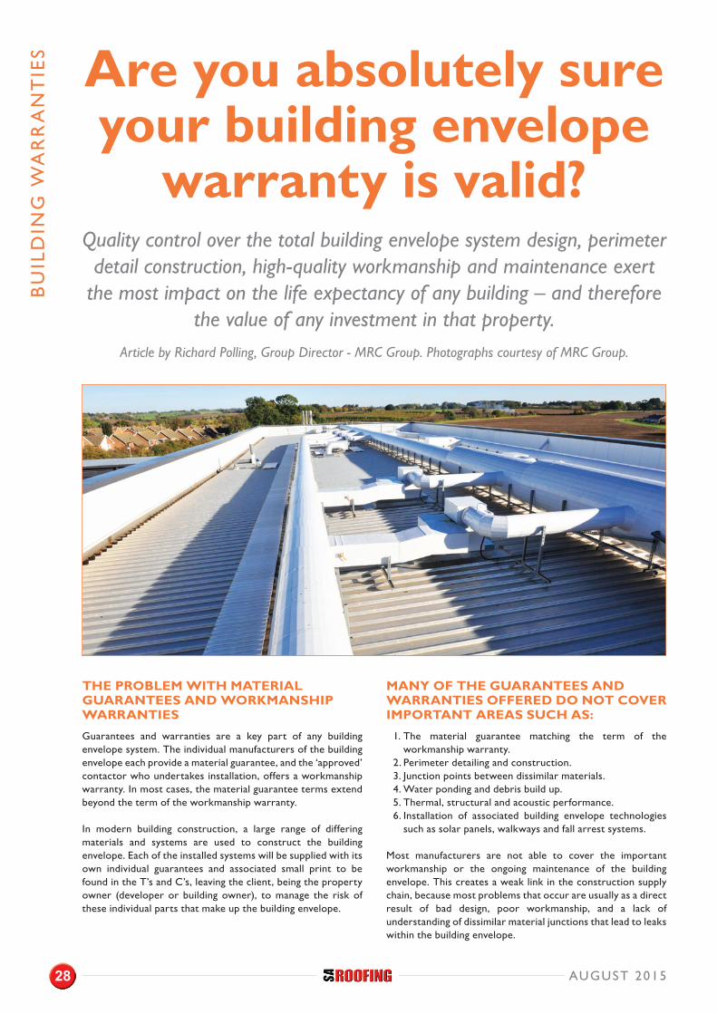
Are you absolutely sure your building envelope
warranty is valid? Quality control over the total building envelope system design, perimeter detail construction, high-quality workmanship and maintenance exert
the most impact on the life expectancy of any building – and therefore the value of any investment in that property.
Article by Richard Polling, Group Director - MRC Group. Photographs courtesy of MRC Group.
AUGUST 201528
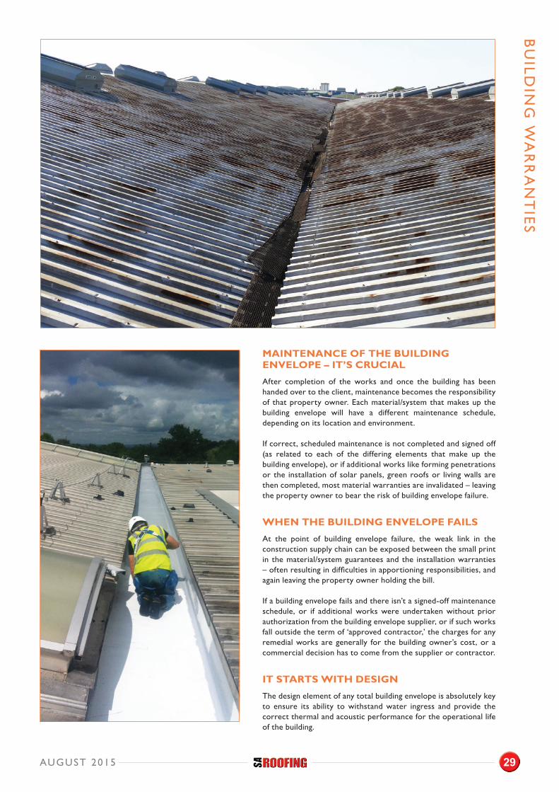
MAINTENANCE OF THE BUILDING ENVELOPE – IT’S CRUCIAL
After completion of the works and once the building has been handed over to the client, maintenance becomes the responsibility of that property owner. Each material/system that makes up the building envelope will have a different maintenance schedule, depending on its location and environment.
If correct, scheduled maintenance is not completed and signed off (as related to each of the differing elements that make up the building envelope), or if additional works like forming penetrations or the installation of solar panels, green roofs or living walls are then completed, most material warranties are invalidated – leaving the property owner to bear the risk of building envelope failure.
WHEN THE BUILDING ENVELOPE FAILS
At the point of building envelope failure, the weak link in the construction supply chain can be exposed between the small print in the material/system guarantees and the installation warranties – often resulting in difficulties in apportioning responsibilities, and again leaving the property owner holding the bill.
If a building envelope fails and there isn’t a signed-off maintenance schedule, or if additional works were undertaken without prior authorization from the building envelope supplier, or if such works fall outside the term of ‘approved contractor,’ the charges for any remedial works are generally for the building owner’s cost, or a commercial decision has to come from the supplier or contractor.
IT STARTS WITH DESIGN
The design element of any total building envelope is absolutely key to ensure its ability to withstand water ingress and provide the correct thermal and acoustic performance for the operational life of the building.
BU
ILDIN
G W
AR
RA
NT
IES
AUGUST 2015 29
BU
ILD
ING
WA
RR
AN
TIE
S
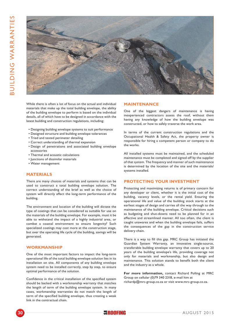
While there is often a lot of focus on the actual and individual materials that make up the total building envelope, the ability of the building envelope to perform is based on the individual details, all of which have to be designed in accordance with the latest building and construction regulations, including:
• Designing building envelope systems to suit performance• Designed structure and building envelope tolerances• Tried and tested perimeter detailing• Correct understanding of thermal expansion • Design of penetrations and associated building envelope
accessories• Thermal and acoustic calculations• Junctions of dissimilar materials• Water management
MATERIALS
There are many choices of materials and systems that can be used to construct a total building envelope solution. The correct understanding of the brief as well as the choice of system will directly affect the long-term performance of the building.
The environment and location of the building will dictate the type of coatings that can be considered as suitable for use on the materials of the building envelope. For example, must it be able to withstand the impact of a highly industrial area, or combat a coastal environment to ensure longevity? Such specialized coatings may cost more at the construction stage, but over the operating life cycle of the building, savings will be generated.
WORKMANSHIP
One of the most important factors to impact the long-term operational life of the total building envelope solution lies in its installation on site. All components of any building envelope system need to be installed correctly, step by step, to ensure optimal performance of the solution.
Confidence in the critical installation of the specified system should be backed with a workmanship warranty that matches the length of term of the building envelope system. In many cases, workmanship warranties do not match the length of term of the specified building envelope, thus creating a weak link in the contractual chain.
MAINTENANCE
One of the biggest dangers of maintenance is having inexperienced contractors assess the roof, without them having any knowledge of how the building envelope was constructed, or how to safely traverse the work area.
In terms of the current construction regulations and the Occupational Health & Safety Act, the property owner is responsible for hiring a competent person or company to do the works.
All installed systems must be maintained, and the scheduled maintenance must be completed and signed off by the supplier of that system. The frequency and manner of such maintenance is determined by the location of the site and the materials/systems installed.
PROTECTING YOUR INVESTMENT
Protecting and maximizing returns is of primary concern for any developer or client, whether it is the initial cost of the building, vacancy levels, or the rental yield. Ensuring the operational life and value of the building stock starts at the earliest stages of design and carries all the way through to the maintenance of the building envelope. Critical decisions such as budgeting and shut-downs need to be planned for in an effective and streamlined manner. All too often, the client is caught unawares and when the building envelope fails, suffers the consequences of the gap in the construction service delivery chain.
There is a way to fill this gap. MRC Group has initiated the Guardian System Warranty, an innovative single-source, transferable building envelope warranty that covers up to 20 years of the building envelope’s life, providing coverage not only for materials and workmanship, but also design and maintenance. This solution stands to benefit both the client and the industry as a whole.
For more information, contact Richard Polling at MRC Group on cellular (0)79 340 2318, e-mail him at [email protected] or visit www.mrc-group.co.za.
AUGUST 201530
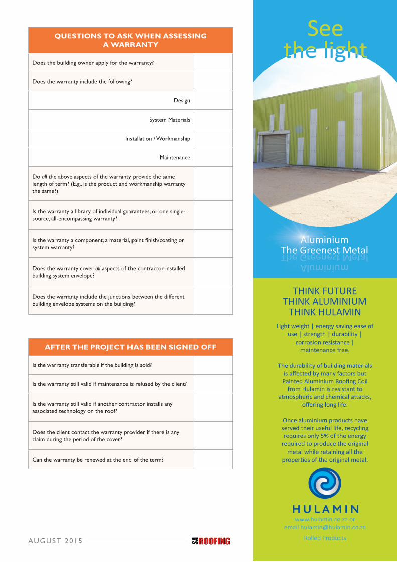
QUESTIONS TO ASK WHEN ASSESSING A WARRANTY
Does the building owner apply for the warranty?
Does the warranty include the following?
Design
System Materials
Installation / Workmanship
Maintenance
Do all the above aspects of the warranty provide the same length of term? (E.g., is the product and workmanship warranty the same?)
Is the warranty a library of individual guarantees, or one single-source, all-encompassing warranty?
Is the warranty a component, a material, paint finish/coating or system warranty?
Does the warranty cover all aspects of the contractor-installed building system envelope?
Does the warranty include the junctions between the different building envelope systems on the building?
AFTER THE PROJECT HAS BEEN SIGNED OFF
Is the warranty transferable if the building is sold?
Is the warranty still valid if maintenance is refused by the client?
Is the warranty still valid if another contractor installs any associated technology on the roof?
Does the client contact the warranty provider if there is any claim during the period of the cover?
Can the warranty be renewed at the end of the term?
32100/1 - Hulamin Roofing Advert Jun 2015 FA.indd 1 2015/06/22 4:44 PM
AUGUST 2015
It’s official. At least 50% of effective communication is visual, which is why lovely, glossy prints adorn top magazines and newspapers and also why some social media platforms have become the virtual
overnight success that they have. With this in mind, the news savvy roofing contractor, equipment supplier, manufacturer, architect and also the designer needs some firm guidelines as to what works for publishers of magazines, books and the like.
SUBMIT PHOTOGRAPHS WITH CONFIDENCE
Leading trade magazines such as SA Roofing constantly receive photographs from readers, contributors, public relations firms and also advertisers who aim to get their message into the magazine as ‘news.’ Accurate photography, along with well prepared editorial is always a welcome addition to business publications, so here are a few guidelines to making your photographs of reproducible news-quality standard.
THE PHOTO MUST TELL A STORY
Think of the photo as a ‘picture story’ in words. The best photos will inform the reader of your message exactly. There are a number of methods that professional photographers use to ensure this. These include:
• Correct usage of light: With digital photography it is easy to do this. If there are dark areas, do use your camera's flash to fill these in.
• Correct composition: Unless you are displaying a photograph of a single item such as a pack shot, the background is important. Put your subject to the side by about a third, so that the background can help fill in the story. However, take care to avoid noisy or irrelevant backgrounds. Clear the background of litter and unnecessary equipment as far as possible. Watch out for commercial signs or logos in the background – editors do not like to publish these.
• Correct height: This is where most amateurs get it wrong. In addition to at shoulder height, try taking your photo at height off a ladder or above a wall – or try kneeling and shooting from the ground. See which version best fits your story.
• Correct angle: Bear in mind that a wide angle changes your perspective. If you zoom right out from an object using your camera lens, objects in the foreground will be much larger than objects in the background. This causes distortion in the images of buildings and anything with straight lines. You can experiment with this effect artistically, but do consider the effect it will have on your picture story.
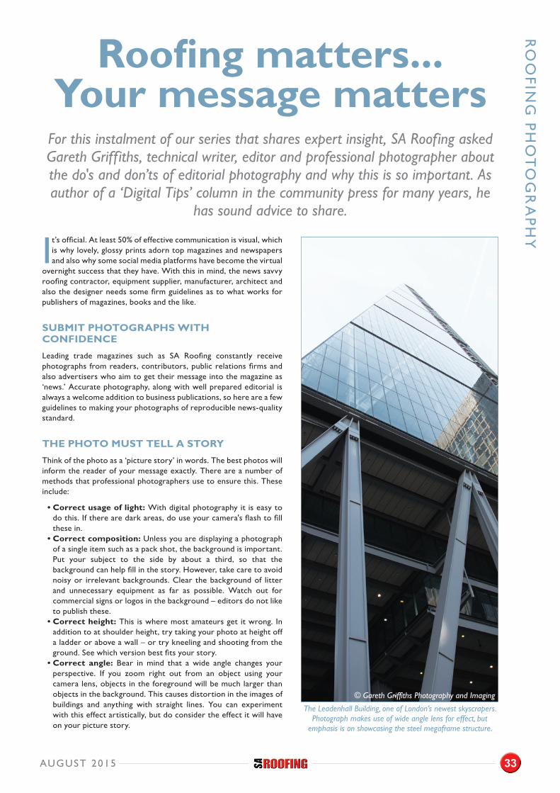
Roofing matters...Your message matters
For this instalment of our series that shares expert insight, SA Roofing asked Gareth Griffiths, technical writer, editor and professional photographer about the do's and don’ts of editorial photography and why this is so important. As author of a ‘Digital Tips’ column in the community press for many years, he
has sound advice to share.
RO
OFIN
G P
HO
TO
GR
AP
HY
The Leadenhall Building, one of London’s newest skyscrapers. Photograph makes use of wide angle lens for effect, but
emphasis is on showcasing the steel megaframe structure.
© Gareth Griffiths Photography and Imaging
AUGUST 2015 33
RO
OFI
NG
PH
OT
OG
RA
PH
Y
PICTURE QUALITY DETERMINES USABILITY
It is crucial to take the photograph at the highest possible resolution. The optimal print resolution sought by most publishers is 300DPI/PPI (dots per inch, or pixels per inch).
Technically speaking, the correct expression of resolution should be a photo's megapixel size. Most magazines printing at A4 size will be content to receive a well composed photograph at 6 megapixels. One point that warrants clarification is that resolution does not always equal file size in megabytes (MB). However, as a rough guide, a file size of 1 megabyte (1MB) is generally acceptable.
It is important to note that pictures taken with smartphones are, in general, not of sufficiently high quality. There are too many variables that you cannot control when using a smartphone.
Another two obvious but critical pointers are to hold the camera still and avoid shooting directly into the sun (you will lose all detail!).
ACCURATE CAPTIONING
Don't assume that the editor or graphic designer will associate your words with the photos you have sent. Use a numerical reference system tied to the file name of the image and keep the caption to about 10 – 20 words maximum. If the photo has reference to any particular section of your editorial, indicate it as such inside the script, e.g. ‘fit photo xxx here.’
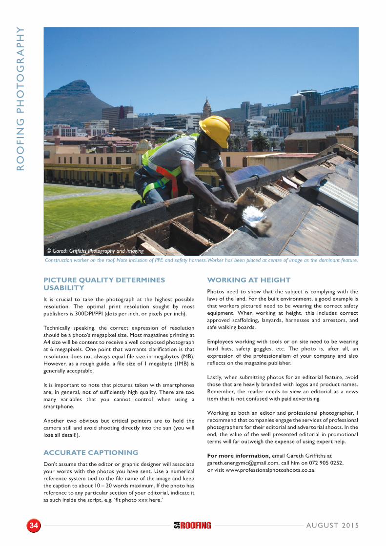
WORKING AT HEIGHT
Photos need to show that the subject is complying with the laws of the land. For the built environment, a good example is that workers pictured need to be wearing the correct safety equipment. When working at height, this includes correct approved scaffolding, lanyards, harnesses and arrestors, and safe walking boards.
Employees working with tools or on site need to be wearing hard hats, safety goggles, etc. The photo is, after all, an expression of the professionalism of your company and also reflects on the magazine publisher.
Lastly, when submitting photos for an editorial feature, avoid those that are heavily branded with logos and product names. Remember, the reader needs to view an editorial as a news item that is not confused with paid advertising.
Working as both an editor and professional photographer, I recommend that companies engage the services of professional photographers for their editorial and advertorial shoots. In the end, the value of the well presented editorial in promotional terms will far outweigh the expense of using expert help.
For more information, email Gareth Griffiths at [email protected], call him on 072 905 0252, or visit www.professionalphotoshoots.co.za.
© Gareth Griffiths Photography and Imaging
Construction worker on the roof. Note inclusion of PPE and safety harness. Worker has been placed at centre of image as the dominant feature.
AUGUST 201534

Leaders in Roof Truss TechnologyFabricators
SheetersErectors
Tilers
STE
EL
AW
AR
DS
201
5 E
NT
RIE
S
AUGUST 201536
Steel leaves a legacy.
SOUTHERN AFRICAN INSTITUTE OFSTEEL CONSTRUCTION
Southern African Institute of Steel ConstructionTel: +27 11 726 6111
Email: [email protected] www.saisc.co.za
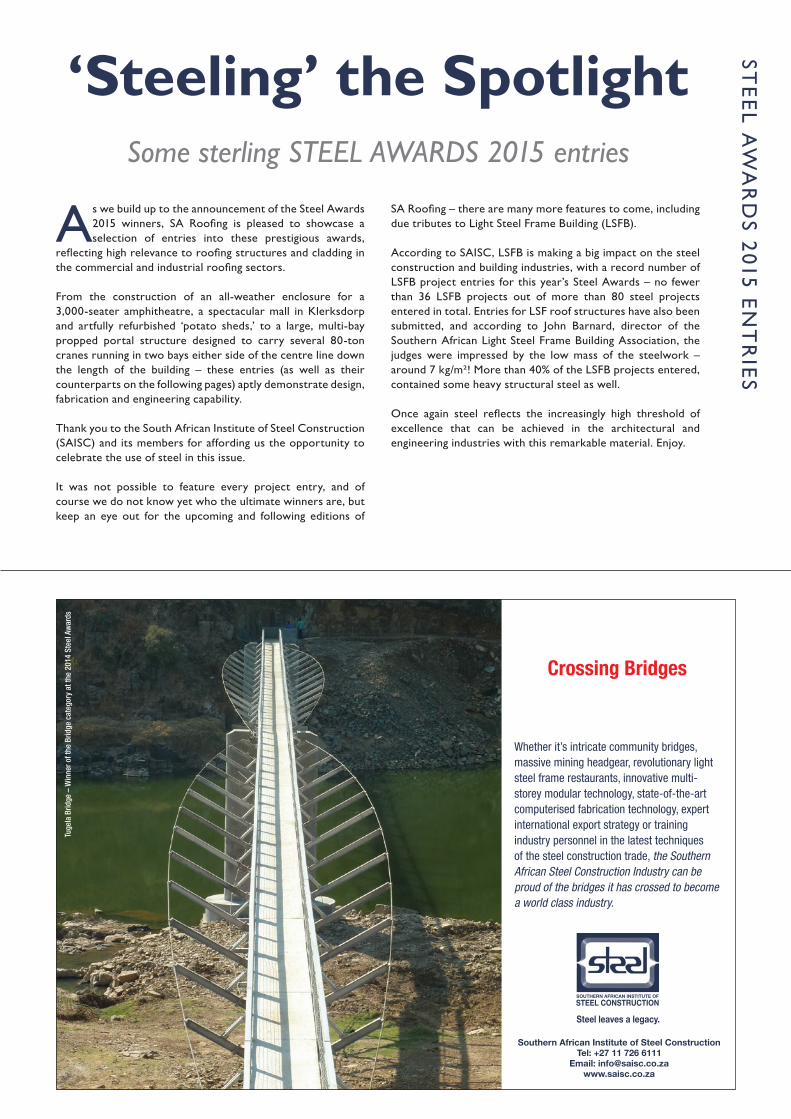
Crossing Bridges
Whether it’s intricate community bridges, massive mining headgear, revolutionary light steel frame restaurants, innovative multi-storey modular technology, state-of-the-art computerised fabrication technology, expert international export strategy or training industry personnel in the latest techniques of the steel construction trade, the Southern African Steel Construction Industry can be proud of the bridges it has crossed to become a world class industry.
Tuge
la B
ridge
– W
inne
r of t
he B
ridge
cat
egor
y at
the
2014
Ste
el A
war
ds
SAISC 210x145 ad.indd 1 2/17/15 3:02 PM
As we build up to the announcement of the Steel Awards 2015 winners, SA Roofing is pleased to showcase a selection of entries into these prestigious awards,
reflecting high relevance to roofing structures and cladding in the commercial and industrial roofing sectors.
From the construction of an all-weather enclosure for a 3,000-seater amphitheatre, a spectacular mall in Klerksdorp and artfully refurbished ‘potato sheds,’ to a large, multi-bay propped portal structure designed to carry several 80-ton cranes running in two bays either side of the centre line down the length of the building – these entries (as well as their counterparts on the following pages) aptly demonstrate design, fabrication and engineering capability.
Thank you to the South African Institute of Steel Construction (SAISC) and its members for affording us the opportunity to celebrate the use of steel in this issue.
It was not possible to feature every project entry, and of course we do not know yet who the ultimate winners are, but keep an eye out for the upcoming and following editions of
SA Roofing – there are many more features to come, including due tributes to Light Steel Frame Building (LSFB).
According to SAISC, LSFB is making a big impact on the steel construction and building industries, with a record number of LSFB project entries for this year’s Steel Awards – no fewer than 36 LSFB projects out of more than 80 steel projects entered in total. Entries for LSF roof structures have also been submitted, and according to John Barnard, director of the Southern African Light Steel Frame Building Association, the judges were impressed by the low mass of the steelwork – around 7 kg/m²! More than 40% of the LSFB projects entered, contained some heavy structural steel as well.
Once again steel reflects the increasingly high threshold of excellence that can be achieved in the architectural and engineering industries with this remarkable material. Enjoy.
‘Steeling’ the SpotlightSome sterling STEEL AWARDS 2015 entries
STE
EL A
WA
RD
S 2015 E
NT
RIE
S
Steel leaves a legacy.
SOUTHERN AFRICAN INSTITUTE OFSTEEL CONSTRUCTION
Southern African Institute of Steel ConstructionTel: +27 11 726 6111
Email: [email protected] www.saisc.co.za
Crossing Bridges
Whether it’s intricate community bridges, massive mining headgear, revolutionary light steel frame restaurants, innovative multi-storey modular technology, state-of-the-art computerised fabrication technology, expert international export strategy or training industry personnel in the latest techniques of the steel construction trade, the Southern African Steel Construction Industry can be proud of the bridges it has crossed to become a world class industry.
Tuge
la B
ridge
– W
inne
r of t
he B
ridge
cat
egor
y at
the
2014
Ste
el A
war
ds
SAISC 210x145 ad.indd 1 2/17/15 3:02 PM
STE
EL
AW
AR
DS
201
5 E
NT
RY
PROJECT SCOPE
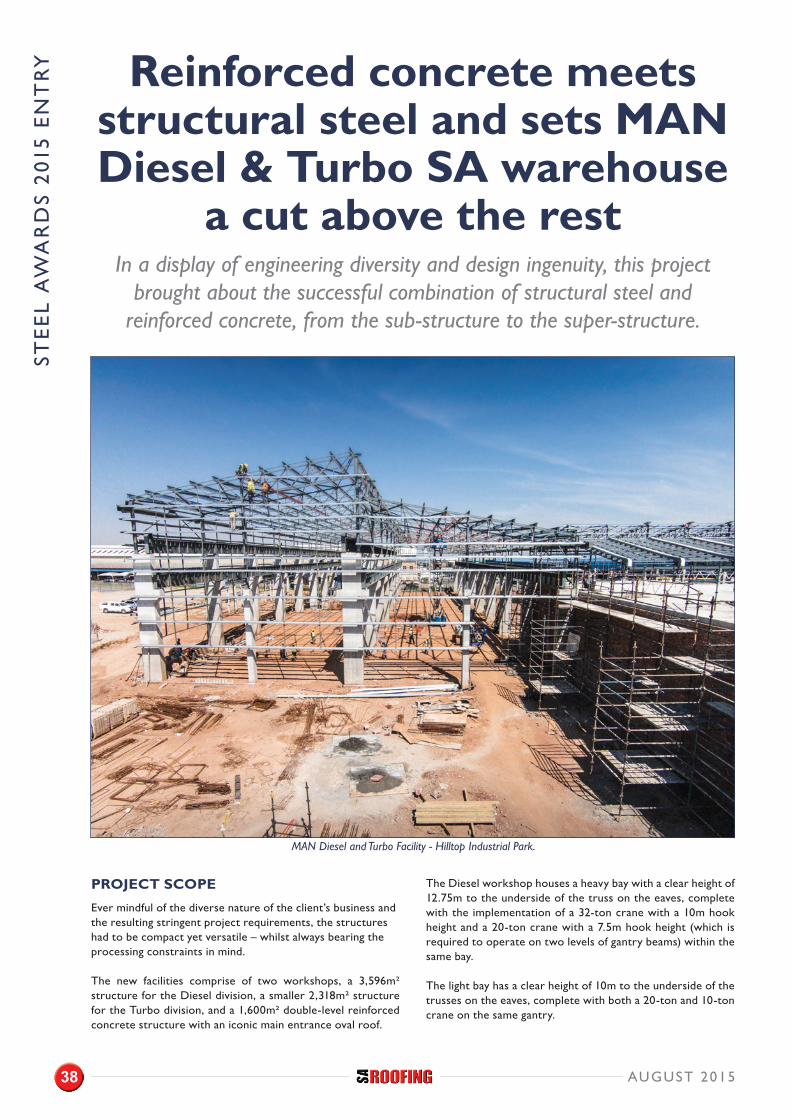
Ever mindful of the diverse nature of the client’s business and the resulting stringent project requirements, the structures had to be compact yet versatile – whilst always bearing the processing constraints in mind.
The new facilities comprise of two workshops, a 3,596m² structure for the Diesel division, a smaller 2,318m² structure for the Turbo division, and a 1,600m² double-level reinforced concrete structure with an iconic main entrance oval roof.
The Diesel workshop houses a heavy bay with a clear height of 12.75m to the underside of the truss on the eaves, complete with the implementation of a 32-ton crane with a 10m hook height and a 20-ton crane with a 7.5m hook height (which is required to operate on two levels of gantry beams) within the same bay.
The light bay has a clear height of 10m to the underside of the trusses on the eaves, complete with both a 20-ton and 10-ton crane on the same gantry.
Reinforced concrete meets structural steel and sets MAN Diesel & Turbo SA warehouse
a cut above the restIn a display of engineering diversity and design ingenuity, this project
brought about the successful combination of structural steel and reinforced concrete, from the sub-structure to the super-structure.
MAN Diesel and Turbo Facility - Hilltop Industrial Park.
AUGUST 201538
STRUCTURAL PROFILES USED: Columns, Beams, IPE’s, Angles, Plate Girders, Lattice Trusses & Metsec TYPE OF CLADDING: Lip Channels STRUCTURAL FRAMING: Beams & Columns
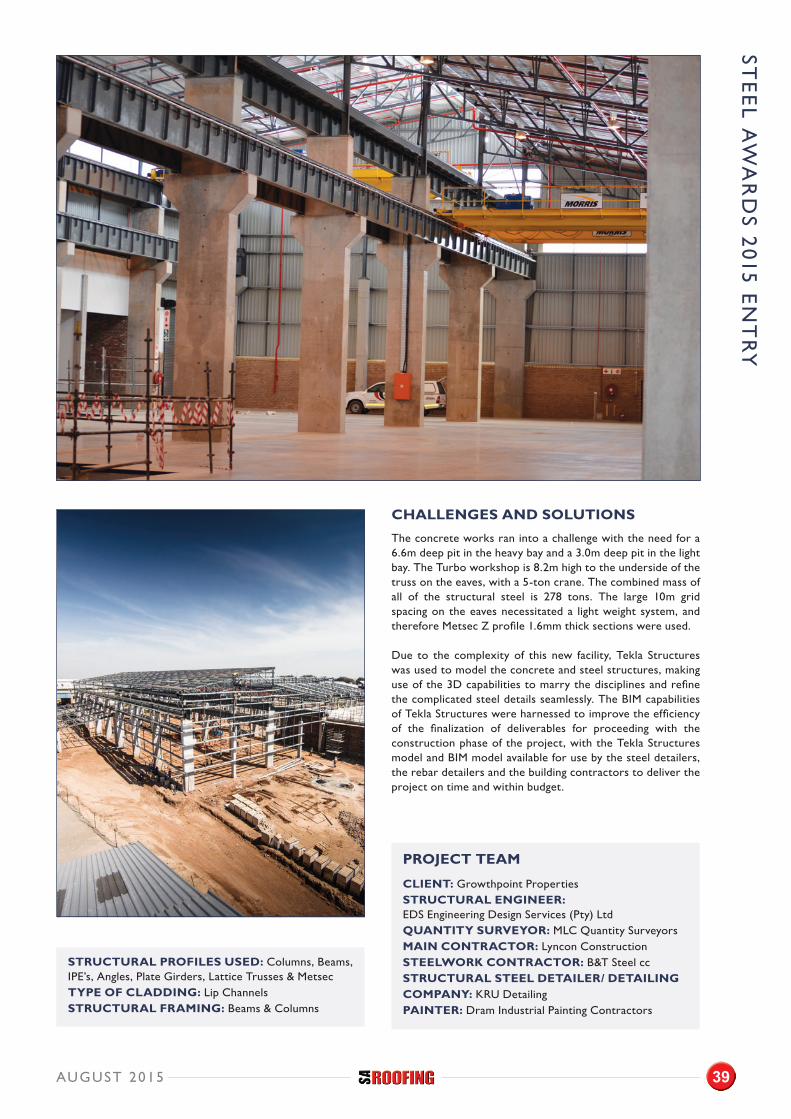
CHALLENGES AND SOLUTIONS
The concrete works ran into a challenge with the need for a 6.6m deep pit in the heavy bay and a 3.0m deep pit in the light bay. The Turbo workshop is 8.2m high to the underside of the truss on the eaves, with a 5-ton crane. The combined mass of all of the structural steel is 278 tons. The large 10m grid spacing on the eaves necessitated a light weight system, and therefore Metsec Z profile 1.6mm thick sections were used.
Due to the complexity of this new facility, Tekla Structures was used to model the concrete and steel structures, making use of the 3D capabilities to marry the disciplines and refine the complicated steel details seamlessly. The BIM capabilities of Tekla Structures were harnessed to improve the efficiency of the finalization of deliverables for proceeding with the construction phase of the project, with the Tekla Structures model and BIM model available for use by the steel detailers, the rebar detailers and the building contractors to deliver the project on time and within budget.
PROJECT TEAM
CLIENT: Growthpoint PropertiesSTRUCTURAL ENGINEER: EDS Engineering Design Services (Pty) LtdQUANTITY SURVEYOR: MLC Quantity SurveyorsMAIN CONTRACTOR: Lyncon ConstructionSTEELWORK CONTRACTOR: B&T Steel ccSTRUCTURAL STEEL DETAILER/ DETAILING COMPANY: KRU DetailingPAINTER: Dram Industrial Painting Contractors
STE
EL A
WA
RD
S 2015 E
NT
RY
AUGUST 2015 39
STE
EL
AW
AR
DS
201
5 E
NT
RY
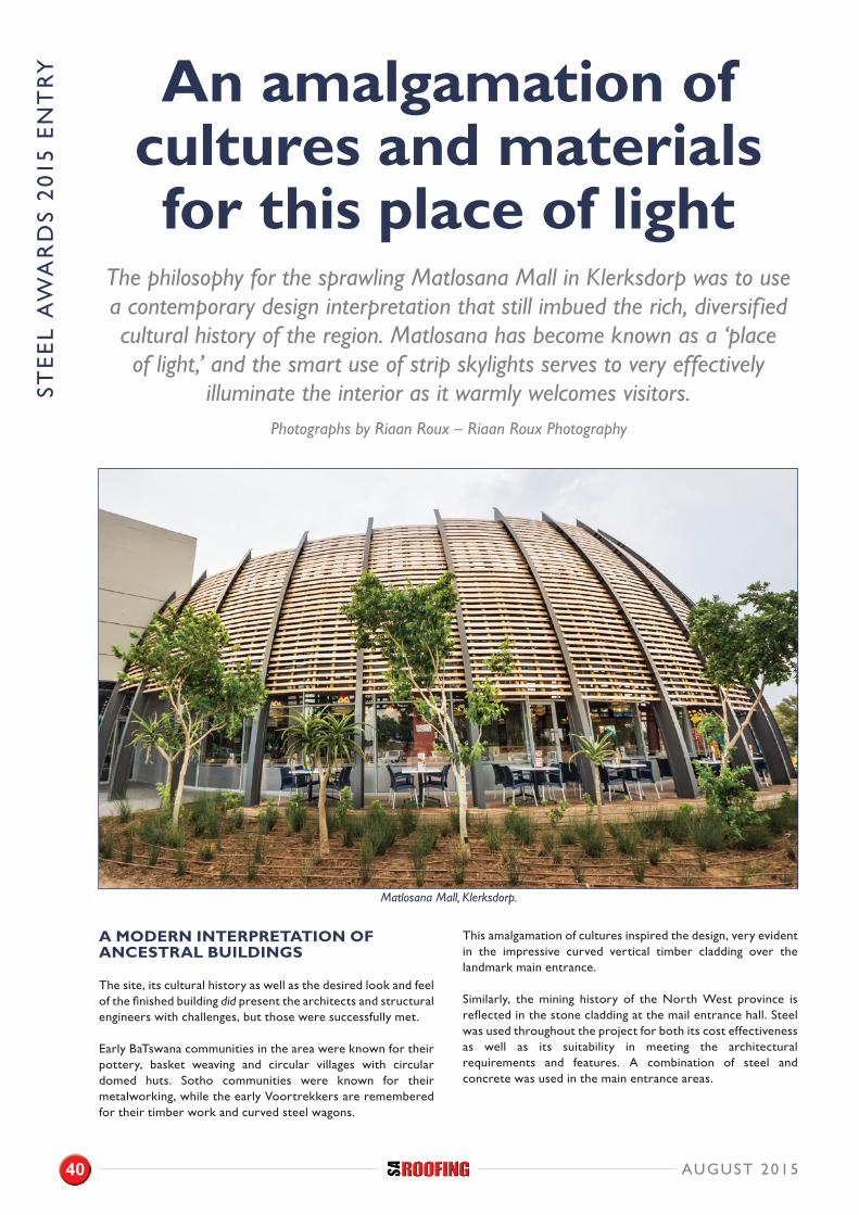
A MODERN INTERPRETATION OF ANCESTRAL BUILDINGS
The site, its cultural history as well as the desired look and feel of the finished building did present the architects and structural engineers with challenges, but those were successfully met.
Early BaTswana communities in the area were known for their pottery, basket weaving and circular villages with circular domed huts. Sotho communities were known for their metalworking, while the early Voortrekkers are remembered for their timber work and curved steel wagons.
This amalgamation of cultures inspired the design, very evident in the impressive curved vertical timber cladding over the landmark main entrance.
Similarly, the mining history of the North West province is reflected in the stone cladding at the mail entrance hall. Steel was used throughout the project for both its cost effectiveness as well as its suitability in meeting the architectural requirements and features. A combination of steel and concrete was used in the main entrance areas.
An amalgamation of cultures and materials for this place of light
The philosophy for the sprawling Matlosana Mall in Klerksdorp was to use a contemporary design interpretation that still imbued the rich, diversified cultural history of the region. Matlosana has become known as a ‘place of light,’ and the smart use of strip skylights serves to very effectively
illuminate the interior as it warmly welcomes visitors.
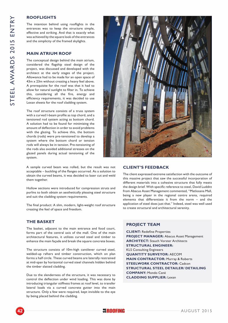
Matlosana Mall, Klerksdorp.
Photographs by Riaan Roux – Riaan Roux Photography
AUGUST 201540
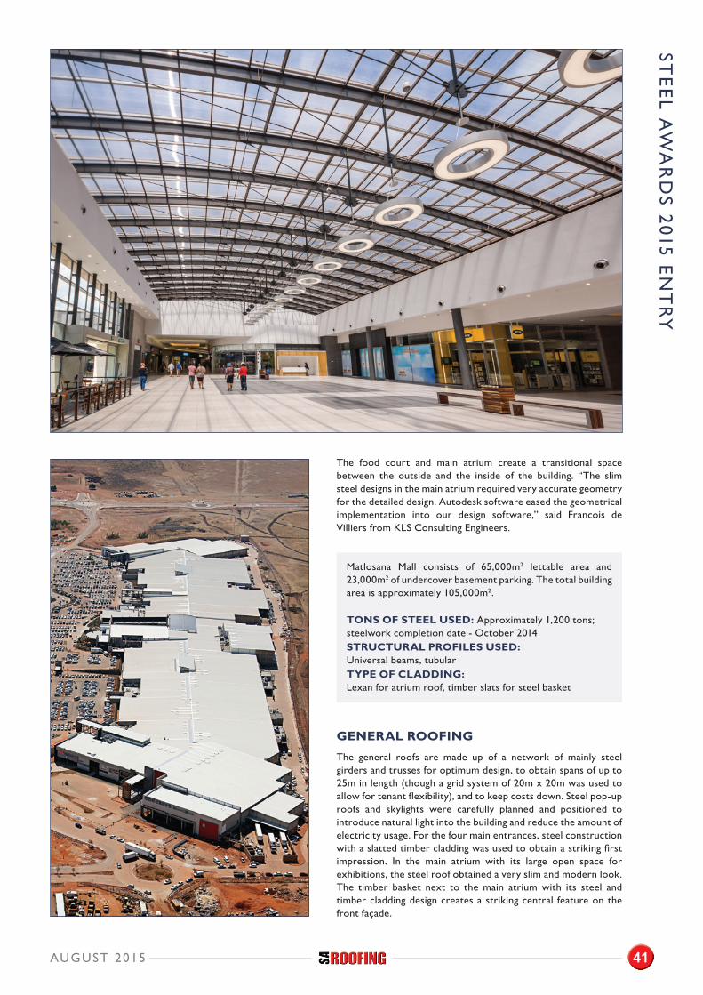
The food court and main atrium create a transitional space between the outside and the inside of the building. “The slim steel designs in the main atrium required very accurate geometry for the detailed design. Autodesk software eased the geometrical implementation into our design software,” said Francois de Villiers from KLS Consulting Engineers.
Matlosana Mall consists of 65,000m2 lettable area and 23,000m2 of undercover basement parking. The total building area is approximately 105,000m2.
TONS OF STEEL USED: Approximately 1,200 tons; steelwork completion date - October 2014STRUCTURAL PROFILES USED: Universal beams, tubular TYPE OF CLADDING: Lexan for atrium roof, timber slats for steel basket
GENERAL ROOFING
The general roofs are made up of a network of mainly steel girders and trusses for optimum design, to obtain spans of up to 25m in length (though a grid system of 20m x 20m was used to allow for tenant flexibility), and to keep costs down. Steel pop-up roofs and skylights were carefully planned and positioned to introduce natural light into the building and reduce the amount of electricity usage. For the four main entrances, steel construction with a slatted timber cladding was used to obtain a striking first impression. In the main atrium with its large open space for exhibitions, the steel roof obtained a very slim and modern look. The timber basket next to the main atrium with its steel and timber cladding design creates a striking central feature on the front façade.
STE
EL A
WA
RD
S 2015 E
NT
RY
AUGUST 2015 41
STE
EL
AW
AR
DS
201
5 E
NT
RY
A sample curved beam was rolled, but the result was not acceptable – buckling of the flanges occurred. As a solution to obtain the curved beams, it was decided to laser cut and weld them together.
Hollow sections were introduced for compression struts and purlins to both obtain an aesthetically pleasing steel structure and suit the cladding system requirements.
The final product: A slim, modern, light-weight roof structure creating the feel of space and freedom.
THE BASKET
The basket, adjacent to the main entrance and food court, forms part of the central axis of the mall. One of the main architectural features, it utilizes curved steel and timber to enhance the main façade and break the square concrete boxes.
The structure consists of 10m-high cantilever curved steel, welded-up rafters and timber construction, which on plan forms a half circle. These curved beams are laterally restrained at mid-span by horizontal curved steel channels hidden behind the timber slatted cladding.
Due to the slenderness of the structure, it was necessary to control the deflection under wind loading. This was done by introducing triangular stiffness frames at roof level, to transfer lateral loads via a curved concrete gutter into the main structure. Only a few were required, kept invisible to the eye by being placed behind the cladding.
CLIENT’S FEEDBACK
The client expressed extreme satisfaction with the outcome of this massive project that saw the successful incorporation of different materials into a cohesive structure that fully meets the design brief. With specific reference to steel, David Ludditt from Abacus Asset Management commented, “Matlosana Mall, being a new player in the regional centre arena, required elements that differentiate it from the norm – and the application of steel does just that.‘’ Indeed, steel was well used to create structural and architectural serenity.
PROJECT TEAM
CLIENT: Redefine PropertiesPROJECT MANAGER: Abacus Asset Management ARCHITECT: Stauch Vorster ArchitectsSTRUCTURAL ENGINEER: KLS Consulting EngineersQUANTITY SURVEYOR: AECOMMAIN CONTRACTOR: Murray & RobertsSTEELWORK CONTRACTOR: Cadcon STRUCTURAL STEEL DETAILER/ DETAILING COMPANY: Mondo Cané CLADDING SUPPLIER: Lexan
ROOFLIGHTS
The intention behind using rooflights in the entrances was to keep the structure simple, effective and striking. And that is exactly what was achieved by the square look of the entrances and the simplicity of the framed skylights.
MAIN ATRIUM ROOF
The conceptual design behind the main atrium, considered the flagship steel design of the project, was discussed and developed with the architect at the early stages of the project. Allowance had to be made for an open space of 43m x 23m without creating a heavy feel above. A prerequisite for the roof was that it had to allow for natural sunlight to filter in. To achieve this, considering all the fire, energy and efficiency requirements, it was decided to use Lexan sheets for the roof cladding system.
The roof structure consists of a truss system with a curved I-beam profile as top chord, and a tensioned rod system acting as bottom chord. A solution had to be found for minimizing the amount of deflection in order to avoid problems with the glazing. To achieve this, the bottom chords (rods) were pre-tensioned to develop a system where the bottom chord or tension rods will always be in tension. Pre-tensioning of the rods also avoided additional stresses on the glazed panels during actual tensioning of the system.
AUGUST 201542
STE
EL
AW
AR
DS
201
5 E
NT
RY
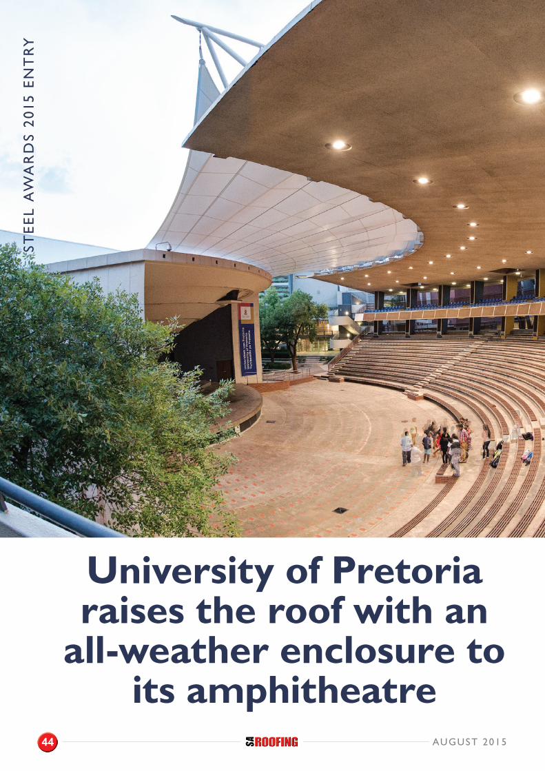
University of Pretoria raises the roof with an
all-weather enclosure to its amphitheatre
AUGUST 201544
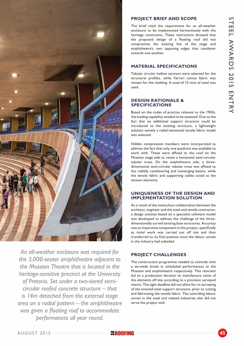
An all-weather enclosure was required for the 3,000-seater amphitheatre adjacent to the Musaion Theatre that is located in the heritage-sensitive precinct at the University of Pretoria. Set under a two-tiered semi-circular roofed concrete structure – that is 14m detached from the external stage
area on a radial pattern – the amphitheatre was given a floating roof to accommodate
performances all year round.
STE
EL A
WA
RD
S 2015 E
NT
RY
PROJECT BRIEF AND SCOPE
The brief cited the requirement for an all-weather enclosure to be implemented harmoniously with the heritage constraints. These restrictions dictated that the proposed design of a floating roof did not compromise the existing line of the stage and amphitheatre’s two opposing edges that cantilever towards one another.
MATERIAL SPECIFICATIONS
Tubular circular hollow sections were selected for the structural profiles, while Ferrari canvas fabric was chosen for the cladding. A total of 15 tons of steel was used.
DESIGN RATIONALE & SPECIFICATIONS
Based on the codes of practice relevant to the 1950s, the loading capability needed to be assessed. Due to the fact that no additional support structure could be introduced to the existing structure, a lightweight solution namely a radial-tensioned tensile fabric model was selected.
Hidden compression members were incorporated to address the fact that only one quadrant was available to work with. These were affixed to the roof on the Musaion stage side to retain a horizontal semi-circular tubular truss. On the amphitheatre side, a three-dimensional semi-circular tubular truss was affixed to the radially cantilevering and converging beams, while the tensile fabric and supporting cables acted as the tension elements.
UNIQUENESS OF THE DESIGN AND IMPLEMENTATION SOLUTION
As a result of the meticulous collaboration between the architect, engineer and the steel and tensile contractor, a design solution based on a specialist software model was developed to address the challenge of the three-dimensionally curved existing base structures. Accuracy was an imperative component in this project, specifically as initial work was carried out off site and then transferred to its final position once the labour unrest in the industry had subsided.
PROJECT CHALLENGES
The construction programme needed to coincide with a six-week break in scheduled performances at the Musaion and amphitheatre respectively. This restraint led to a production decision to manufacture some of the elements off site according to a precision surveyed matrix. The tight deadline did not allow for re-surveying of the erected steel support structure, prior to cutting and fabricating the tensile fabric. The coinciding labour unrest in the steel and related industries also did not serve the project well.
AUGUST 2015 45
STE
EL
AW
AR
DS
201
5 E
NT
RY
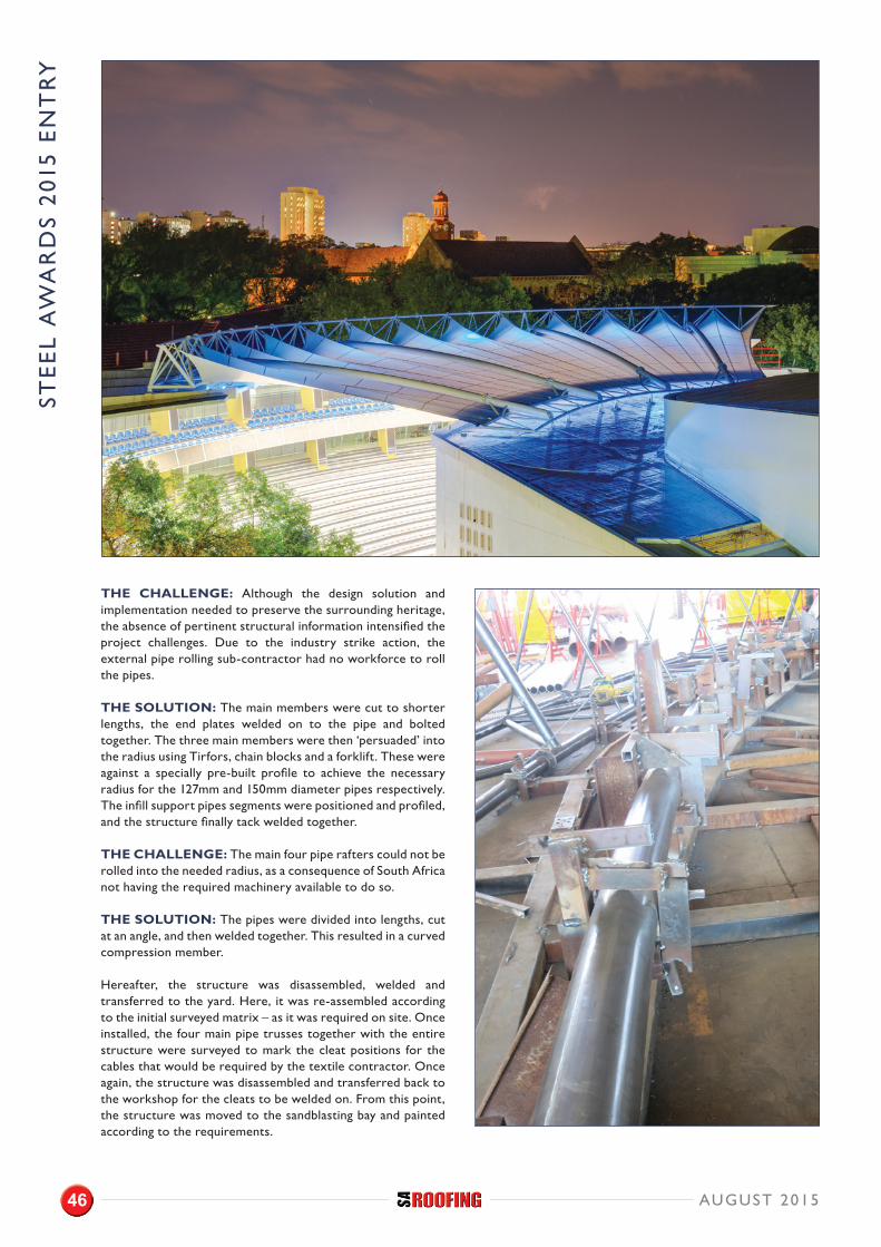
THE CHALLENGE: Although the design solution and implementation needed to preserve the surrounding heritage, the absence of pertinent structural information intensified the project challenges. Due to the industry strike action, the external pipe rolling sub-contractor had no workforce to roll the pipes.
THE SOLUTION: The main members were cut to shorter lengths, the end plates welded on to the pipe and bolted together. The three main members were then ‘persuaded’ into the radius using Tirfors, chain blocks and a forklift. These were against a specially pre-built profile to achieve the necessary radius for the 127mm and 150mm diameter pipes respectively. The infill support pipes segments were positioned and profiled, and the structure finally tack welded together.
THE CHALLENGE: The main four pipe rafters could not be rolled into the needed radius, as a consequence of South Africa not having the required machinery available to do so.
THE SOLUTION: The pipes were divided into lengths, cut at an angle, and then welded together. This resulted in a curved compression member.
Hereafter, the structure was disassembled, welded and transferred to the yard. Here, it was re-assembled according to the initial surveyed matrix – as it was required on site. Once installed, the four main pipe trusses together with the entire structure were surveyed to mark the cleat positions for the cables that would be required by the textile contractor. Once again, the structure was disassembled and transferred back to the workshop for the cleats to be welded on. From this point, the structure was moved to the sandblasting bay and painted according to the requirements.
AUGUST 201546

THE CHALLENGE: The erection stage presented its share of challenges, setting out a distance limitation of 80m to the nearest concrete surface sufficiently capable of supporting the crane while it hoisted the sizeable components into position.
THE SOLUTION: While conducting production at the workshop, the smaller sections were fabricated. A spider crane was then used, on the rubber tracts, to get close to the building to lift the sections 11m to the roof. Once this was in place, the various sections were then positioned manually and bolted together to form the final curve.
The floor area between the amphitheatre and the Musaion Theatre comprises of heritage-sensitive brick paving. It was therefore essential to use large spreader planks to protect the paving to build a double tower. Thereafter, the pipe rafters were lifted into their respective positions with a chain block up to the 14m above Natural Ground Level (NGL) mark. To achieve complete installation, this process was repeated four times.
COMPLETION
The completion date for the steelwork was 12 December 2014.
OUTCOME
Despite stringent project requirements and specifications, coupled with strike action from the workforce that merely added to the challenge, hard work and quality workmanship prevailed. The contractor initiated creative solutions for transporting elements to the factory to continue the workflow. Working closely with the engineers, shorter bolted truss elements needed to be introduced, and although this was not the initial planned course of action, it succeeded in getting the project done in the timeliest manner possible amidst the strike action. Today, the building stands tall, or is that raises the roof, for all to enjoy.
PROJECT TEAM
CLIENT: University of Pretoria PROJECT MANAGER: ARC Architectural Consultants (Pretoria) (Pty) LtdARCHITECT: ARC Architectural Consultants (Pretoria) (Pty) LtdSTRUCTURAL ENGINEER: WSP Group Africa (Pty) Ltd QUANTITY SURVEYOR: Bham Tayob Khan Pretoria Inc.STEELWORK CONTRACTOR: CICon PM SERGE FERRARI TENSILE MEMBRANE AND STAINLESS STEEL CABLES AND FITTINGS: Texwise Architectural Structures (Pty) LtdELECTRICAL ENGINEERS: TPS Consulting Engineers
AUGUST 2015
10 Thora Cresent, Wynberg, Sandton, Johannesburg011 262 4151charles@frontier-electroinics.co.zabrinnosa.co.zafacebook.com/brinnoafrica
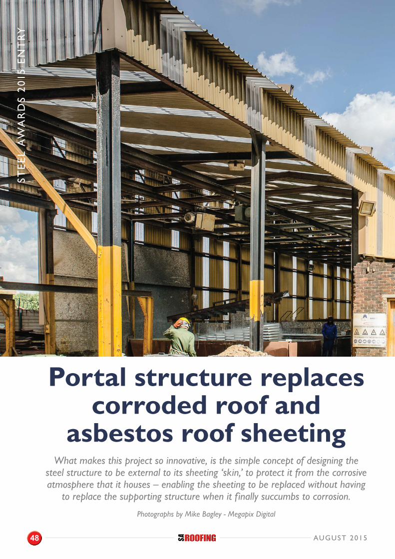
STE
EL
AW
AR
DS
201
5 E
NT
RY
Portal structure replaces corroded roof and
asbestos roof sheetingWhat makes this project so innovative, is the simple concept of designing the
steel structure to be external to its sheeting ‘skin,’ to protect it from the corrosive atmosphere that it houses – enabling the sheeting to be replaced without having
to replace the supporting structure when it finally succumbs to corrosion.
Photographs by Mike Bagley - Megapix Digital
AUGUST 201548
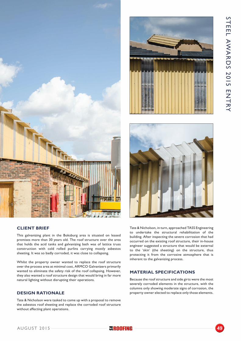
STE
EL A
WA
RD
S 2015 E
NT
RY
CLIENT BRIEF
This galvanizing plant in the Boksburg area is situated on leased premises more than 30 years old. The roof structure over the area that holds the acid tanks and galvanizing bath was of lattice truss construction with cold rolled purlins carrying mostly asbestos sheeting. It was so badly corroded, it was close to collapsing.
Whilst the property owner wanted to replace the roof structure over the process area at minimal cost, ARMCO Galvanizers primarily wanted to eliminate the safety risk of the roof collapsing. However, they also wanted a roof structure design that would bring in far more natural lighting without disrupting their operations.
DESIGN RATIONALE
Tate & Nicholson were tasked to come up with a proposal to remove the asbestos roof sheeting and replace the corroded roof structure without affecting plant operations.
Tate & Nicholson, in turn, approached TASS Engineering to undertake the structural rehabilitation of the building. After inspecting the severe corrosion that had occurred on the existing roof structure, their in-house engineer suggested a structure that would be external to the ‘skin’ (the sheeting) on the structure, thus protecting it from the corrosive atmosphere that is inherent to the galvanizing process.
MATERIAL SPECIFICATIONS
Because the roof structure and side girts were the most severely corroded elements in the structure, with the columns only showing moderate signs of corrosion, the property owner elected to replace only those elements.
AUGUST 2015 49
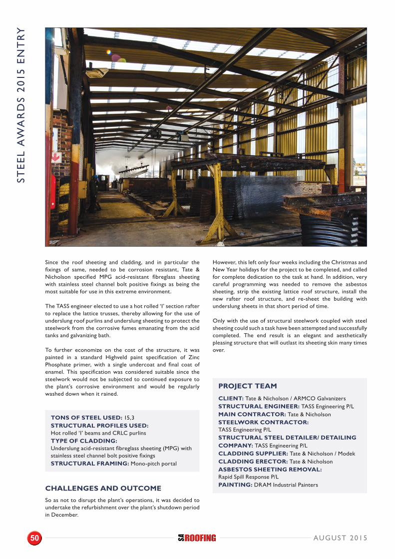
STE
EL
AW
AR
DS
201
5 E
NT
RY
Since the roof sheeting and cladding, and in particular the fixings of same, needed to be corrosion resistant, Tate & Nicholson specified MPG acid-resistant fibreglass sheeting with stainless steel channel bolt positive fixings as being the most suitable for use in this extreme environment.
The TASS engineer elected to use a hot rolled ‘I’ section rafter to replace the lattice trusses, thereby allowing for the use of underslung roof purlins and underslung sheeting to protect the steelwork from the corrosive fumes emanating from the acid tanks and galvanizing bath.
To further economize on the cost of the structure, it was painted in a standard Highveld paint specification of Zinc Phosphate primer, with a single undercoat and final coat of enamel. This specification was considered suitable since the steelwork would not be subjected to continued exposure to the plant’s corrosive environment and would be regularly washed down when it rained.
TONS OF STEEL USED: 15,3 STRUCTURAL PROFILES USED: Hot rolled ‘I’ beams and CRLC purlins TYPE OF CLADDING: Underslung acid-resistant fibreglass sheeting (MPG) with stainless steel channel bolt positive fixingsSTRUCTURAL FRAMING: Mono-pitch portal
CHALLENGES AND OUTCOME
So as not to disrupt the plant’s operations, it was decided to undertake the refurbishment over the plant’s shutdown period in December.
However, this left only four weeks including the Christmas and New Year holidays for the project to be completed, and called for complete dedication to the task at hand. In addition, very careful programming was needed to remove the asbestos sheeting, strip the existing lattice roof structure, install the new rafter roof structure, and re-sheet the building with underslung sheets in that short period of time.
Only with the use of structural steelwork coupled with steel sheeting could such a task have been attempted and successfully completed. The end result is an elegant and aesthetically pleasing structure that will outlast its sheeting skin many times over.
PROJECT TEAM
CLIENT: Tate & Nicholson / ARMCO GalvanizersSTRUCTURAL ENGINEER: TASS Engineering P/LMAIN CONTRACTOR: Tate & NicholsonSTEELWORK CONTRACTOR: TASS Engineering P/LSTRUCTURAL STEEL DETAILER/ DETAILING COMPANY: TASS Engineering P/LCLADDING SUPPLIER: Tate & Nicholson / ModekCLADDING ERECTOR: Tate & NicholsonASBESTOS SHEETING REMOVAL: Rapid Spill Response P/LPAINTING: DRAM Industrial Painters
AUGUST 201550
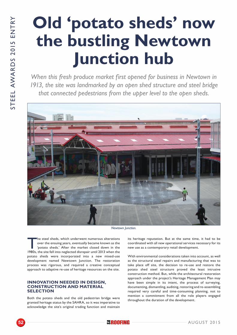
The steel sheds, which underwent numerous alterations over the ensuing years, eventually became known as the ‘potato sheds.’ After the market closed down in the
1980s, the site fell into neglected disrepair until 2013 when the potato sheds were incorporated into a new mixed-use development named Newtown Junction. The restoration process was rigorous, and required a creative conceptual approach to adaptive re-use of heritage resources on the site.
INNOVATION NEEDED IN DESIGN, CONSTRUCTION AND MATERIAL SELECTION
Both the potato sheds and the old pedestrian bridge were granted heritage status by the SAHRA, so it was imperative to acknowledge the site’s original trading function and maintain
its heritage reputation. But at the same time, it had to be coordinated with all new operational services necessary for its new use as a contemporary retail development.
With environmental considerations taken into account, as well as the structural steel repairs and manufacturing that was to take place off site, the decision to re-use and restore the potato shed steel structure proved the least intrusive construction method. But, while the architectural restoration approach under the project’s Heritage Management Plan may have been simple in its intent, the process of surveying, documenting, dismantling, auditing, restoring and re-assembling required very careful and time-consuming planning, not to mention a commitment from all the role players engaged throughout the duration of the development.
Old ‘potato sheds’ now the bustling Newtown
Junction hubWhen this fresh produce market first opened for business in Newtown in 1913, the site was landmarked by an open shed structure and steel bridge
that connected pedestrians from the upper level to the open sheds.
Newtown Junction.
AUGUST 201552
STE
EL
AW
AR
DS
201
5 E
NT
RY
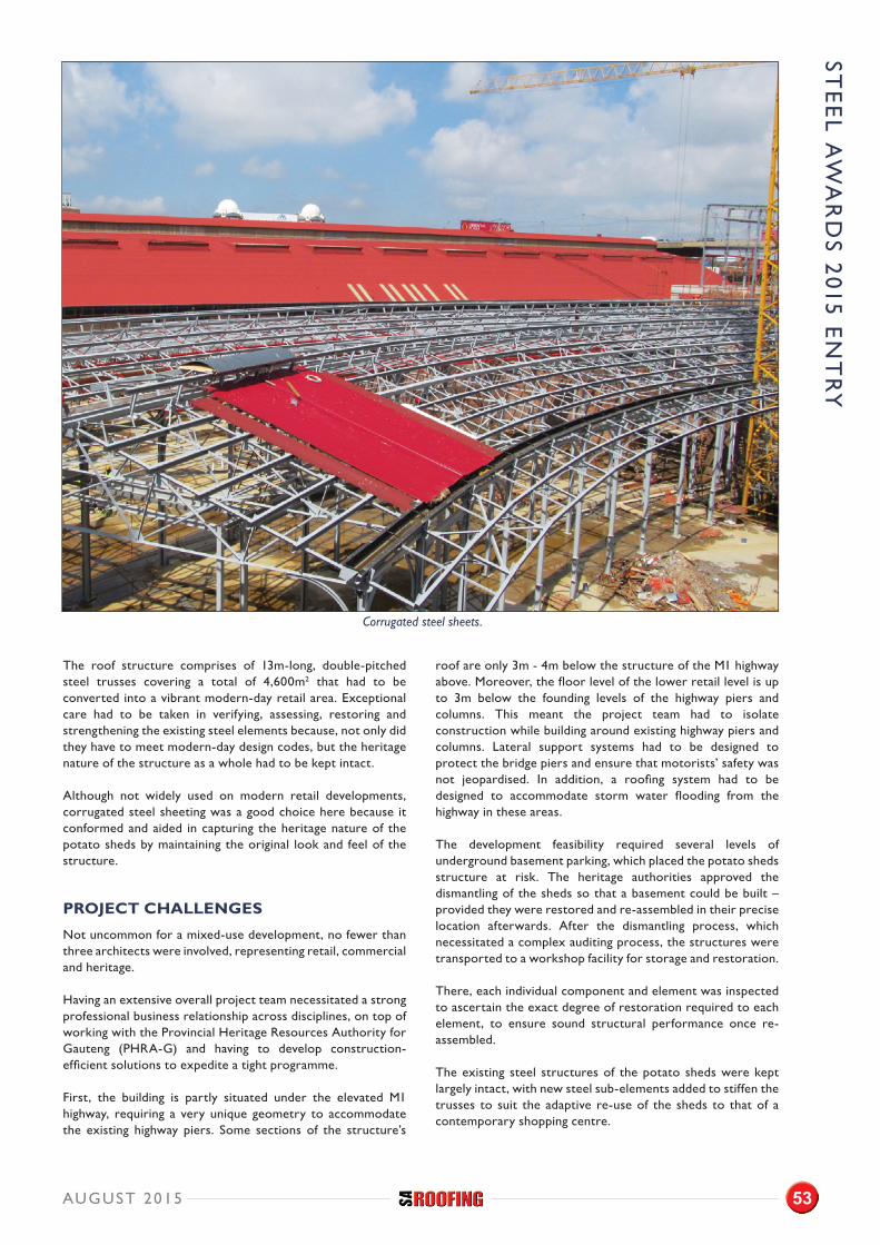
The roof structure comprises of 13m-long, double-pitched steel trusses covering a total of 4,600m2 that had to be converted into a vibrant modern-day retail area. Exceptional care had to be taken in verifying, assessing, restoring and strengthening the existing steel elements because, not only did they have to meet modern-day design codes, but the heritage nature of the structure as a whole had to be kept intact.
Although not widely used on modern retail developments, corrugated steel sheeting was a good choice here because it conformed and aided in capturing the heritage nature of the potato sheds by maintaining the original look and feel of the structure.
PROJECT CHALLENGES
Not uncommon for a mixed-use development, no fewer than three architects were involved, representing retail, commercial and heritage.
Having an extensive overall project team necessitated a strong professional business relationship across disciplines, on top of working with the Provincial Heritage Resources Authority for Gauteng (PHRA-G) and having to develop construction-efficient solutions to expedite a tight programme.
First, the building is partly situated under the elevated M1 highway, requiring a very unique geometry to accommodate the existing highway piers. Some sections of the structure’s
roof are only 3m - 4m below the structure of the M1 highway above. Moreover, the floor level of the lower retail level is up to 3m below the founding levels of the highway piers and columns. This meant the project team had to isolate construction while building around existing highway piers and columns. Lateral support systems had to be designed to protect the bridge piers and ensure that motorists’ safety was not jeopardised. In addition, a roofing system had to be designed to accommodate storm water flooding from the highway in these areas.
The development feasibility required several levels of underground basement parking, which placed the potato sheds structure at risk. The heritage authorities approved the dismantling of the sheds so that a basement could be built – provided they were restored and re-assembled in their precise location afterwards. After the dismantling process, which necessitated a complex auditing process, the structures were transported to a workshop facility for storage and restoration.
There, each individual component and element was inspected to ascertain the exact degree of restoration required to each element, to ensure sound structural performance once re-assembled.
The existing steel structures of the potato sheds were kept largely intact, with new steel sub-elements added to stiffen the trusses to suit the adaptive re-use of the sheds to that of a contemporary shopping centre.
Corrugated steel sheets.
AUGUST 2015 53
STE
EL A
WA
RD
S 2015 E
NT
RY
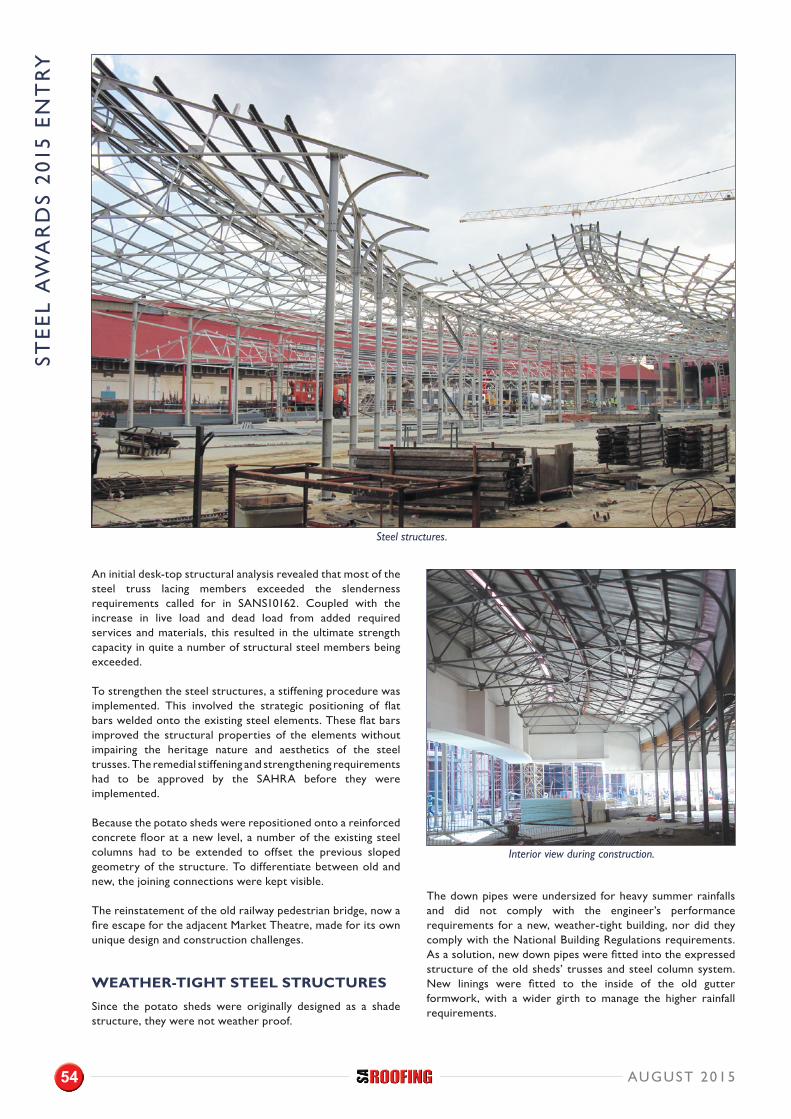
An initial desk-top structural analysis revealed that most of the steel truss lacing members exceeded the slenderness requirements called for in SANS10162. Coupled with the increase in live load and dead load from added required services and materials, this resulted in the ultimate strength capacity in quite a number of structural steel members being exceeded.
To strengthen the steel structures, a stiffening procedure was implemented. This involved the strategic positioning of flat bars welded onto the existing steel elements. These flat bars improved the structural properties of the elements without impairing the heritage nature and aesthetics of the steel trusses. The remedial stiffening and strengthening requirements had to be approved by the SAHRA before they were implemented.
Because the potato sheds were repositioned onto a reinforced concrete floor at a new level, a number of the existing steel columns had to be extended to offset the previous sloped geometry of the structure. To differentiate between old and new, the joining connections were kept visible.
The reinstatement of the old railway pedestrian bridge, now a fire escape for the adjacent Market Theatre, made for its own unique design and construction challenges.
WEATHER-TIGHT STEEL STRUCTURES
Since the potato sheds were originally designed as a shade structure, they were not weather proof.
The down pipes were undersized for heavy summer rainfalls and did not comply with the engineer’s performance requirements for a new, weather-tight building, nor did they comply with the National Building Regulations requirements. As a solution, new down pipes were fitted into the expressed structure of the old sheds’ trusses and steel column system. New linings were fitted to the inside of the old gutter formwork, with a wider girth to manage the higher rainfall requirements.
Interior view during construction.
AUGUST 201554
STE
EL
AW
AR
DS
201
5 E
NT
RY
Steel structures.
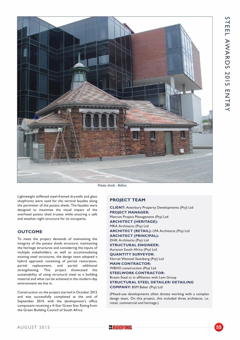
Lightweight stiffened steel-framed drywalls and glass shopfronts were used for the vertical façades along the perimeter of the potato sheds. The façades were designed to maximize the visual impact of the overhead potato shed trusses while ensuring a safe and weather-tight structure for its occupants.
OUTCOME
To meet the project demands of maintaining the integrity of the potato sheds structure, maintaining the heritage structures and considering the inputs of multiple stakeholders, as well as accommodating existing steel structures, the design team adopted a hybrid approach consisting of partial restoration, partial replacement, and partial additional strengthening. This project showcased the sustainability of using structural steel as a building material and what can be achieved in the modern-day environment we live in.
Construction on the project started in October 2012 and was successfully completed at the end of September 2014, with the development’s office component receiving a 4-Star Green Star Rating from the Green Building Council of South Africa.
PROJECT TEAM
CLIENT: Atterbury Property Developments (Pty) LtdPROJECT MANAGER: Metrum Project Management (Pty) LtdARCHITECT (HERITAGE): MRA Architects (Pty) LtdARCHITECT (RETAIL): LPA Architects (Pty) LtdARCHITECT (PRINCIPAL): DHK Architects (Pty) LtdSTRUCTURAL ENGINEER: Aurecon South Africa (Pty) LtdQUANTITY SURVEYOR: Norval Wentzel Steinberg (Pty) LtdMAIN CONTRACTOR: WBHO construction (Pty) LtdSTEELWORK CONTRACTOR: Braam Staal cc in affiliation with Lem GroupSTRUCTURAL STEEL DETAILER/ DETAILING COMPANY: BSM Baker (Pty) Ltd
(Mixed-use developments often dictate working with a complex design team. On this project, this included three architects, i.e. retail, commercial and heritage.)
AUGUST 2015 55
STE
EL A
WA
RD
S 2015 E
NT
RY
Potato sheds - Before.
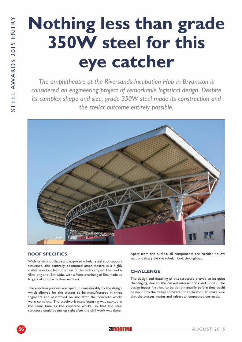
Nothing less than grade 350W steel for this
eye catcher The amphitheatre at the Riversands Incubation Hub in Bryanston is
considered an engineering project of remarkable logistical design. Despite its complex shape and size, grade 350W steel made its construction and
the stellar outcome entirely possible.
ROOF SPECIFICS
With its distinct shape and exposed tubular steel roof support structure, the centrally positioned amphitheatre is a highly visible standout from the rest of the Hub campus. The roof is 45m long and 15m wide, with a front overhang of 5m, made up largely of circular hollow sections.
The erection process was sped up considerably by the design, which allowed for the trusses to be manufactured in three segments and assembled on site after the concrete works were complete. The steelwork manufacturing was started at the same time as the concrete works, so that the steel structure could be put up right after the civil work was done.
Apart from the purlins, all components are circular hollow sections that yield the tubular look throughout.
CHALLENGE
The design and detailing of this structure proved to be quite challenging, due to the curved intersections and slopes. The design inputs first had to be done manually before they could be input into the design software for application, to make sure that the trusses, nodes and rafters all connected correctly.
AUGUST 201556
STE
EL
AW
AR
DS
201
5 E
NT
RY
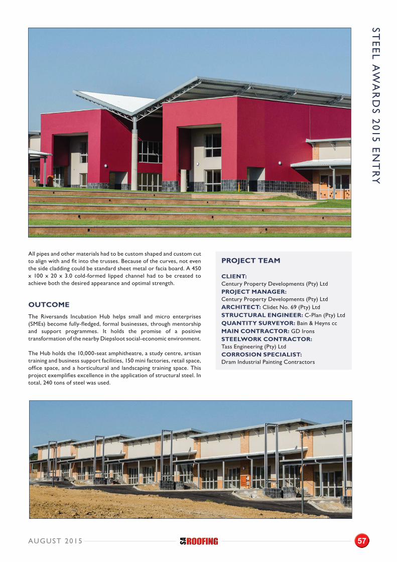
STE
EL A
WA
RD
S 2015 E
NT
RY
AUGUST 2015 57
All pipes and other materials had to be custom shaped and custom cut to align with and fit into the trusses. Because of the curves, not even the side cladding could be standard sheet metal or facia board. A 450 x 100 x 20 x 3.0 cold-formed lipped channel had to be created to achieve both the desired appearance and optimal strength.
OUTCOME
The Riversands Incubation Hub helps small and micro enterprises (SMEs) become fully-fledged, formal businesses, through mentorship and support programmes. It holds the promise of a positive transformation of the nearby Diepsloot social-economic environment.
The Hub holds the 10,000-seat amphitheatre, a study centre, artisan training and business support facilities, 150 mini factories, retail space, office space, and a horticultural and landscaping training space. This project exemplifies excellence in the application of structural steel. In total, 240 tons of steel was used.
PROJECT TEAM
CLIENT: Century Property Developments (Pty) LtdPROJECT MANAGER: Century Property Developments (Pty) LtdARCHITECT: Clidet No. 69 (Pty) LtdSTRUCTURAL ENGINEER: C-Plan (Pty) LtdQUANTITY SURVEYOR: Bain & Heyns ccMAIN CONTRACTOR: GD IronsSTEELWORK CONTRACTOR: Tass Engineering (Pty) LtdCORROSION SPECIALIST: Dram Industrial Painting Contractors
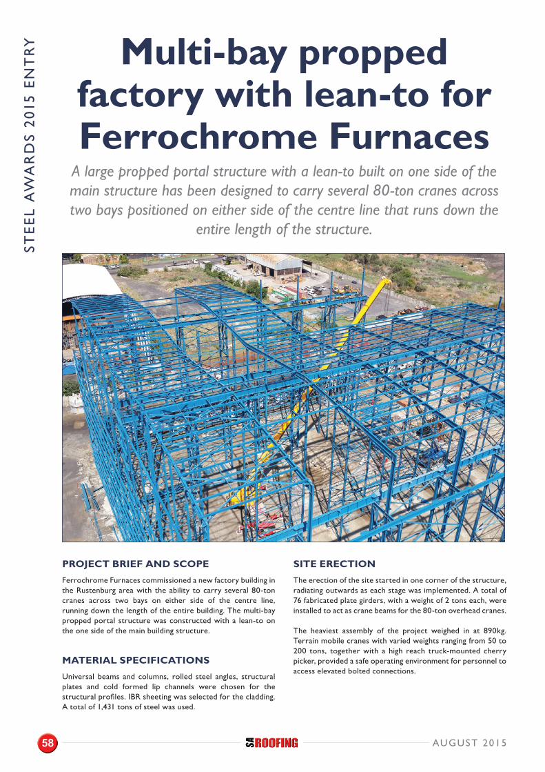
Multi-bay propped factory with lean-to for Ferrochrome Furnaces
A large propped portal structure with a lean-to built on one side of the main structure has been designed to carry several 80-ton cranes across two bays positioned on either side of the centre line that runs down the
entire length of the structure.
PROJECT BRIEF AND SCOPE
Ferrochrome Furnaces commissioned a new factory building in the Rustenburg area with the ability to carry several 80-ton cranes across two bays on either side of the centre line, running down the length of the entire building. The multi-bay propped portal structure was constructed with a lean-to on the one side of the main building structure.
MATERIAL SPECIFICATIONS
Universal beams and columns, rolled steel angles, structural plates and cold formed lip channels were chosen for the structural profiles. IBR sheeting was selected for the cladding. A total of 1,431 tons of steel was used.
SITE ERECTION
The erection of the site started in one corner of the structure, radiating outwards as each stage was implemented. A total of 76 fabricated plate girders, with a weight of 2 tons each, were installed to act as crane beams for the 80-ton overhead cranes.
The heaviest assembly of the project weighed in at 890kg. Terrain mobile cranes with varied weights ranging from 50 to 200 tons, together with a high reach truck-mounted cherry picker, provided a safe operating environment for personnel to access elevated bolted connections.
AUGUST 201558
STE
EL
AW
AR
DS
201
5 E
NT
RY
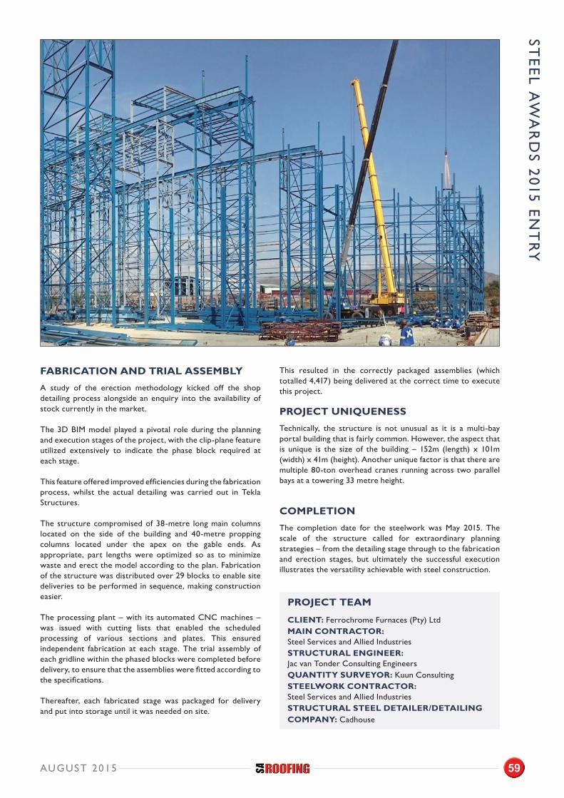
FABRICATION AND TRIAL ASSEMBLY
A study of the erection methodology kicked off the shop detailing process alongside an enquiry into the availability of stock currently in the market.
The 3D BIM model played a pivotal role during the planning and execution stages of the project, with the clip-plane feature utilized extensively to indicate the phase block required at each stage.
This feature offered improved efficiencies during the fabrication process, whilst the actual detailing was carried out in Tekla Structures.
The structure compromised of 38-metre long main columns located on the side of the building and 40-metre propping columns located under the apex on the gable ends. As appropriate, part lengths were optimized so as to minimize waste and erect the model according to the plan. Fabrication of the structure was distributed over 29 blocks to enable site deliveries to be performed in sequence, making construction easier.
The processing plant – with its automated CNC machines – was issued with cutting lists that enabled the scheduled processing of various sections and plates. This ensured independent fabrication at each stage. The trial assembly of each gridline within the phased blocks were completed before delivery, to ensure that the assemblies were fitted according to the specifications.
Thereafter, each fabricated stage was packaged for delivery and put into storage until it was needed on site.
This resulted in the correctly packaged assemblies (which totalled 4,417) being delivered at the correct time to execute this project.
PROJECT UNIQUENESS
Technically, the structure is not unusual as it is a multi-bay portal building that is fairly common. However, the aspect that is unique is the size of the building – 152m (length) x 101m (width) x 41m (height). Another unique factor is that there are multiple 80-ton overhead cranes running across two parallel bays at a towering 33 metre height.
COMPLETION
The completion date for the steelwork was May 2015. The scale of the structure called for extraordinary planning strategies – from the detailing stage through to the fabrication and erection stages, but ultimately the successful execution illustrates the versatility achievable with steel construction.
PROJECT TEAM
CLIENT: Ferrochrome Furnaces (Pty) LtdMAIN CONTRACTOR: Steel Services and Allied Industries STRUCTURAL ENGINEER: Jac van Tonder Consulting EngineersQUANTITY SURVEYOR: Kuun ConsultingSTEELWORK CONTRACTOR: Steel Services and Allied IndustriesSTRUCTURAL STEEL DETAILER/DETAILING COMPANY: Cadhouse
STE
EL A
WA
RD
S 2015 E
NT
RY
AUGUST 2015 59
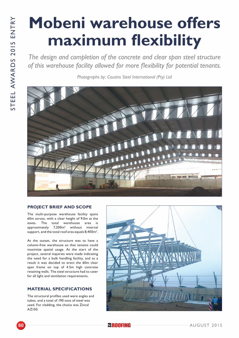
PROJECT BRIEF AND SCOPE
The multi-purpose warehouse facility spans 60m across, with a clear height of 9.0m at the eaves. The total warehouse area is approximately 7,200m2 without internal support, and the total roof area equals 8,400m2.
At the outset, the structure was to have a column-free warehouse so that tenants could maximize spatial usage. At the start of the project, several inquiries were made indicating the need for a bulk handling facility, and as a result it was decided to erect the 60m clear span frame on top of 4.5m high concrete retaining walls. The steel structure had to cater for all light and ventilation requirements.
MATERIAL SPECIFICATIONS
The structural profiles used were angles and tubes, and a total of 190 tons of steel was used. For cladding, the choice was Zincal AZ150.
Mobeni warehouse offers maximum flexibility
The design and completion of the concrete and clear span steel structure of this warehouse facility allowed for more flexibility for potential tenants.
Photographs by: Cousins Steel International (Pty) Ltd
AUGUST 201560
STE
EL
AW
AR
DS
201
5 E
NT
RY
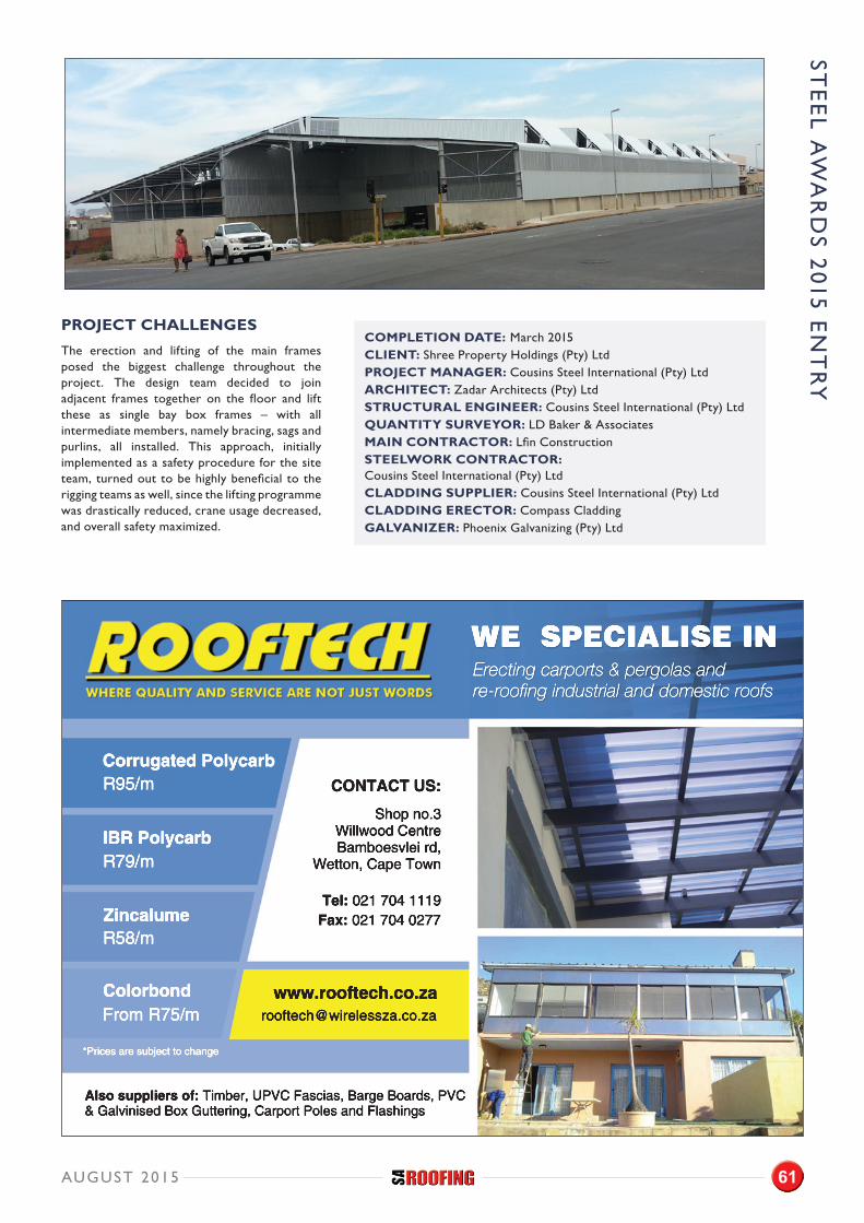
PROJECT CHALLENGES
The erection and lifting of the main frames posed the biggest challenge throughout the project. The design team decided to join adjacent frames together on the floor and lift these as single bay box frames – with all intermediate members, namely bracing, sags and purlins, all installed. This approach, initially implemented as a safety procedure for the site team, turned out to be highly beneficial to the rigging teams as well, since the lifting programme was drastically reduced, crane usage decreased, and overall safety maximized.
COMPLETION DATE: March 2015 CLIENT: Shree Property Holdings (Pty) LtdPROJECT MANAGER: Cousins Steel International (Pty) LtdARCHITECT: Zadar Architects (Pty) LtdSTRUCTURAL ENGINEER: Cousins Steel International (Pty) LtdQUANTITY SURVEYOR: LD Baker & AssociatesMAIN CONTRACTOR: Lfin ConstructionSTEELWORK CONTRACTOR: Cousins Steel International (Pty) LtdCLADDING SUPPLIER: Cousins Steel International (Pty) LtdCLADDING ERECTOR: Compass CladdingGALVANIZER: Phoenix Galvanizing (Pty) Ltd
STE
EL A
WA
RD
S 2015 E
NT
RY
WE SPECIALISE INErecting carports & pergolas and re-roofing industrial and domestic roofs
Also suppliers of: Timber, UPVC Fascias, Barge Boards, PVC & Galvinised Box Guttering, Carport Poles and Flashings
Corrugated Polycarb
IBR Polycarb
R95/m
R79/m
ZincalumeR58/m
Colorbond
CONTACT US:
Shop no.3Willwood CentreBamboesvlei rd,
Wetton, Cape Town
Tel: 021 704 1119Fax: Fax: 021 704 0277
*Prices are subject to change
From R75/m
AUGUST 2015 61
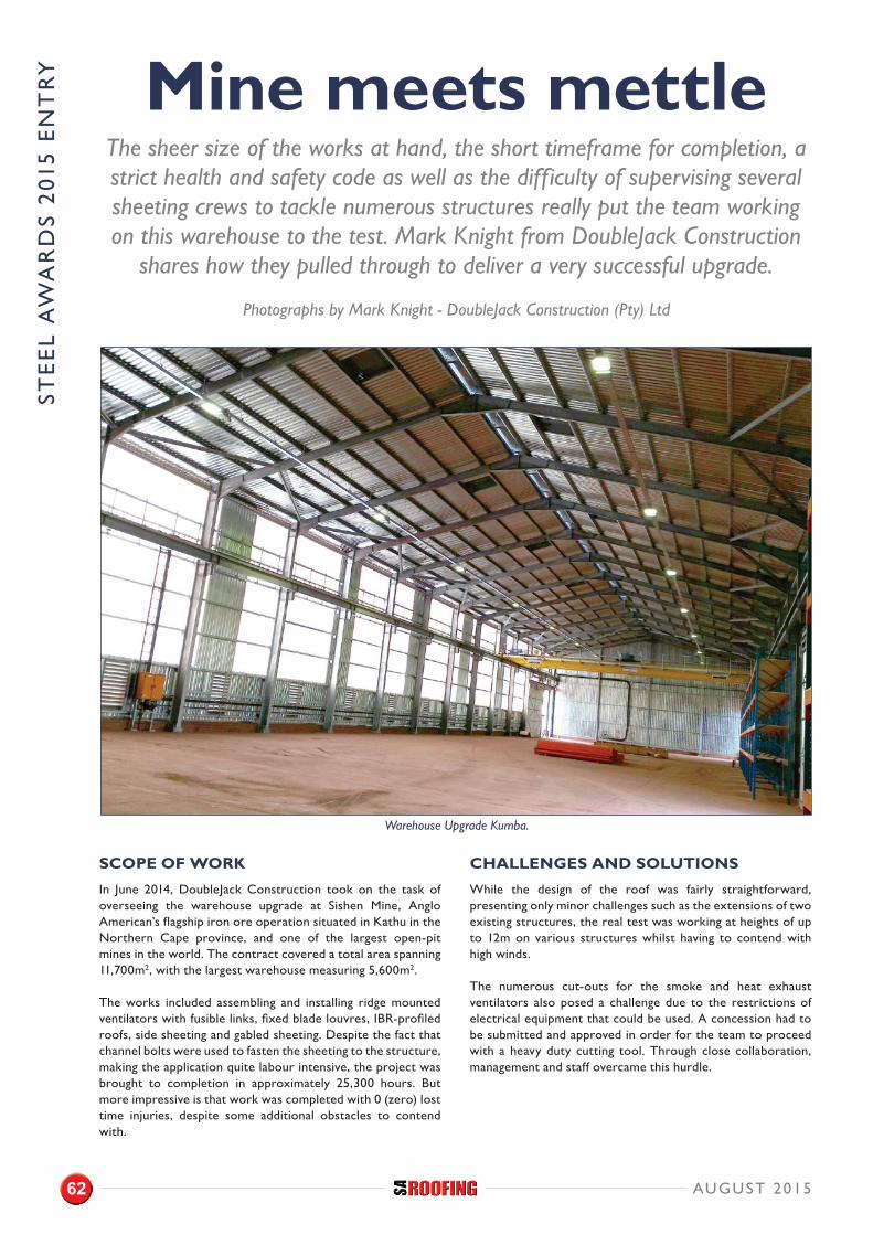
STE
EL
AW
AR
DS
201
5 E
NT
RY Mine meets mettle
The sheer size of the works at hand, the short timeframe for completion, a strict health and safety code as well as the difficulty of supervising several sheeting crews to tackle numerous structures really put the team working on this warehouse to the test. Mark Knight from DoubleJack Construction
shares how they pulled through to deliver a very successful upgrade.
Warehouse Upgrade Kumba.
Photographs by Mark Knight - DoubleJack Construction (Pty) Ltd
SCOPE OF WORK
In June 2014, DoubleJack Construction took on the task of overseeing the warehouse upgrade at Sishen Mine, Anglo American’s flagship iron ore operation situated in Kathu in the Northern Cape province, and one of the largest open-pit mines in the world. The contract covered a total area spanning 11,700m2, with the largest warehouse measuring 5,600m2.
The works included assembling and installing ridge mounted ventilators with fusible links, fixed blade louvres, IBR-profiled roofs, side sheeting and gabled sheeting. Despite the fact that channel bolts were used to fasten the sheeting to the structure, making the application quite labour intensive, the project was brought to completion in approximately 25,300 hours. But more impressive is that work was completed with 0 (zero) lost time injuries, despite some additional obstacles to contend with.
CHALLENGES AND SOLUTIONS
While the design of the roof was fairly straightforward, presenting only minor challenges such as the extensions of two existing structures, the real test was working at heights of up to 12m on various structures whilst having to contend with high winds.
The numerous cut-outs for the smoke and heat exhaust ventilators also posed a challenge due to the restrictions of electrical equipment that could be used. A concession had to be submitted and approved in order for the team to proceed with a heavy duty cutting tool. Through close collaboration, management and staff overcame this hurdle.
AUGUST 201562
Using specialized channel bolts to fasten the sheeting to the structures required a labour-intensive effort.
On-site units for the project included two cherry pickers and two scissor jacks. Extensive use of the MEWPS (Mobile Elevated Working Platforms) were necessary due to the rigorous safety restrictions both inside and outside the structure.
“Although gremlins crept in from time to time causing havoc with the plant, we managed to overcome these little critters and were able to keep to our tight schedule,” comments Knight.
SPECIFICATIONS AND AESTHETICS
The site-specific flashings above door rails that had to be site-measured and installed proved to be quite a task, but the team’s skill set was up to the challenge and the flashings were installed exactly per the client’s requirements.
A specialized gutter and downpipe, inclusive of the various accessories, had to be fabricated off site. The highly experienced staff of DoubleJack Construction took care of the complex installation.
Materials used: 0.8mm and 0.58mm thick galvanized Z275 IBR 686 profiled roof and side sheeting; 1.25mm thick Opal 65 IBR 686 profiled polycarbonate side sheeting for natural light; 600mm throat natural and smoke continuous ridge mounted ventilator with 72˚C fusible link; smoke and heat exhaust ventilators with 72˚C fusible link; and fixed blade louvres.
CONCLUSION
The client’s satisfaction with the upgrade is evident in the fact that additional works were awarded to DoubleJack Construction at the conclusion of this project in November 2014.
PROJECT TEAM
CLIENT: Kumba Iron Ore LtdPROJECT MANAGER: Kumba Iron Ore LtdARCHITECT: N/ASTRUCTURAL ENGINEER: Kariba MineralsQUANTITY SURVEYOR: PCC Quantity SurveyorsMAIN CONTRACTOR: Botes & Kennedy Manyano (Pty) LtdSTEEL CONTRACTOR: Omni Struct Nkosi (Pty) LtdCLADDING SPECIALISTS: DoubleJack Construction (Pty) Ltd
STE
EL A
WA
RD
S 2015 E
NT
RY
AUGUST 2015 63

FREE EXPO ANDWORKSHOP PASS
Valued at R200
Conference Trade Expo∙
Conference Trade Expo∙
ConferenceTrade Expo
ConferenceTrade Expo
12 – 13 August 2015Cape Town International Convention Centre
If you manufacture, sell, specify or work with construction in
any capacity then this is your show!
WHY ATTEND THE EVENT?
• DevelopyourskillsduringFREEworkshopsandtrainingontheexhibitionfloor
• Meettheentireconstructionvaluechain
• WIN!Luckydrawprizestobewon
Networkingopportunities
[email protected] www.cape-construction.co.za
Association and strategic partners
Date:Wednesday12August2015
Time:17:00-19:30
Dress:Businesscasual
NETWORKINg INVITATION
Tuesday12August201511:00–18:00
EXPO HOURS
Wednesday13August201510:30–16:00
Getyourfreeticketbyvisitingeasycode.com/ccregAndusethe*VALIDATIONCODEontheTOPtoredeemthisvoucherandenjoyfreeentry
HOW TO REgISTER
ExhibitionHall1&2,GroundfloorCapeTownInternationalConventionCentre,CapeTown
ADDRESS
WHAT TO EXPECT?
3000+ visitors
100+ exhibiting companies
20+ participating partners
13 FREE workshops
CapeConstructionExpo @CT_Construction #capeconstruction2015 Cape Construction
SEE, TOUCH AND EXPLOREthesolutionsoftomorrowfrom100+exhibitorswhowillbedisplaying:
Chemicals and admixtures Consultants Contracting services Construction tools and equipment Finance and insurance Finishing and facing materials Flooring Formwork and scaffolding HVAC Landscaping products and services
Paints and coatings Retailers Roofing Safety and security Sealants and insulation Software and IT Specialist contractors Transport and logistics
*VIP CODE: SAR01
Conference Trade Expo∙
Conference Trade Expo∙
12 – 13 August 2015, Cape Town International Convention Centre
HOST MEDIA PARTNERS
CapeConstructionExpo CT_Construction Cape Construction
CONTACT RASHAAD ESSOP
+27 21 700 4356
www.cape-construction.co.za
Participate as a SPONSOR
or EXHIBITOR and expand
your business network!
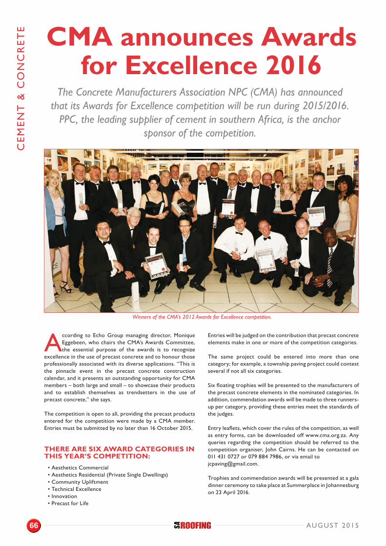
CE
ME
NT
& C
ON
CR
ET
E
According to Echo Group managing director, Monique Eggebeen, who chairs the CMA’s Awards Committee, the essential purpose of the awards is to recognize
excellence in the use of precast concrete and to honour those professionally associated with its diverse applications. “This is the pinnacle event in the precast concrete construction calendar, and it presents an outstanding opportunity for CMA members – both large and small – to showcase their products and to establish themselves as trendsetters in the use of precast concrete,” she says.
The competition is open to all, providing the precast products entered for the competition were made by a CMA member. Entries must be submitted by no later than 16 October 2015.
THERE ARE SIX AWARD CATEGORIES IN THIS YEAR’S COMPETITION:
• Aesthetics Commercial• Aesthetics Residential (Private Single Dwellings)• Community Upliftment• Technical Excellence• Innovation• Precast for Life
Entries will be judged on the contribution that precast concrete elements make in one or more of the competition categories.
The same project could be entered into more than one category; for example, a township paving project could contest several if not all six categories.
Six floating trophies will be presented to the manufacturers of the precast concrete elements in the nominated categories. In addition, commendation awards will be made to three runners-up per category, providing these entries meet the standards of the judges.
Entry leaflets, which cover the rules of the competition, as well as entry forms, can be downloaded off www.cma.org.za. Any queries regarding the competition should be referred to the competition organiser, John Cairns. He can be contacted on 011 431 0727 or 079 884 7986, or via email to [email protected].
Trophies and commendation awards will be presented at a gala dinner ceremony to take place at Summerplace in Johannesburg on 23 April 2016.
CMA announces Awards for Excellence 2016
The Concrete Manufacturers Association NPC (CMA) has announced that its Awards for Excellence competition will be run during 2015/2016.
PPC, the leading supplier of cement in southern Africa, is the anchor sponsor of the competition.
Winners of the CMA’s 2012 Awards for Excellence competition.
AUGUST 201566
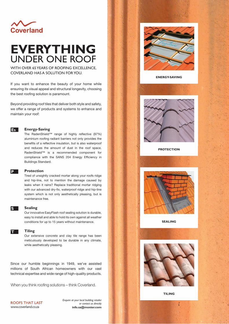
Es
P
S
T
EVERYTHING UNDER ONE ROOF
00652 - MONIER - ROOFING SOLUTIONS - PRINT AD - RP.indd 1 2015/06/04 5:04 PM