Embed Size (px)
Citation preview
Sadhana Vol. 38, Part 5, October 2013, pp. 925–943. c© Indian Academy of Sciences
Safety features in nuclear power plants to eliminatethe need of emergency planning in public domain
P K VIJAYAN∗, M T KAMBLE, A K NAYAK,K K VAZE and R K SINHA
Reactor Design and Development Group, Bhabha Atomic Research Centre,Trombay, Mumbai 400 085, Indiae-mail: [email protected]
Abstract. Following the Fukushima accident, the safety features of Nuclear PowerPlants (NPP) are being re-examined worldwide including India to demonstrate capa-bilities to cope with severe accidents. In order to restore public confidence and supportfor nuclear power, it is felt necessary to design future NPPs with near zero impactoutside the plant boundary and thus enabling elimination of emergency planning inpublic domain. Authors have identified a set of safety features which are needed to beincorporated in advanced reactors to achieve this goal. These features enabling pre-vention, termination, mitigation and containment of radioactivity for beyond designbasis accidents arising from extreme natural events are essential for achieving the goalof elimination of emergency planning in public domain. Inherent safety characteris-tics, passive and engineered safety features to achieve these functions are discussed inthis paper. Present trends and future developments in this direction are also describedbriefly.
Keywords. Advanced nuclear reactors; nuclear power plant accidents; emergencyplanning; passive features; inherent characteristics; decay heat removal.
1. Introduction
Nuclear power plants (NPPs) are serving the mankind for nearly six decades now and currentlyabout 437 of them are operating in 30 countries, with installed capacity of 372 GWe, generat-ing 2518 Giga units of electricity in 2011 which is about 12.3 % of world electricity production(Nuclear Energy Institute, October 2012). They have avoided and continue to avoid release ofabout 8 million tones of CO2 into the atmosphere per day contributing to the prevention ofglobal warming and climate change. While high level nuclear waste is extremely small in quan-tity and contained, NPPs provide electricity without any toxic release during normal operation.Presently, 64 new NPPs are under construction in 14 countries. However, three major accidents
∗For correspondence
925
926 P K Vijayan et al
over a period of six decades including the recent Fukushima accident have shaken the public con-fidence in nuclear energy and its safety record. In order to restore public confidence and supportfor nuclear power plants, it is felt necessary to design them with practically no impact in publicdomain under postulated design basis as well as beyond design basis accidents and thus elimi-nating the need for emergency planning in public domain. This paper is an attempt to prescribethe safety features required in such NPPs.
2. Emergency planning in public domain—present status
Nuclear power plants (NPPs) are designed, constructed, commissioned and operated in confor-mity with existing stringent nuclear safety standards implemented and monitored by regulatorybodies. These standards ensure an adequate margin of safety so that NPPs can be operated with-out undue radiological risks to the plant personnel or members of the public. Notwithstandingthese safety standards, it is necessary to develop, as a measure of abundant caution and in con-formity with international practice, emergency response plans so that any event, with a potentialto result in undue radiological risk to plant personnel and public, could be handled safely.
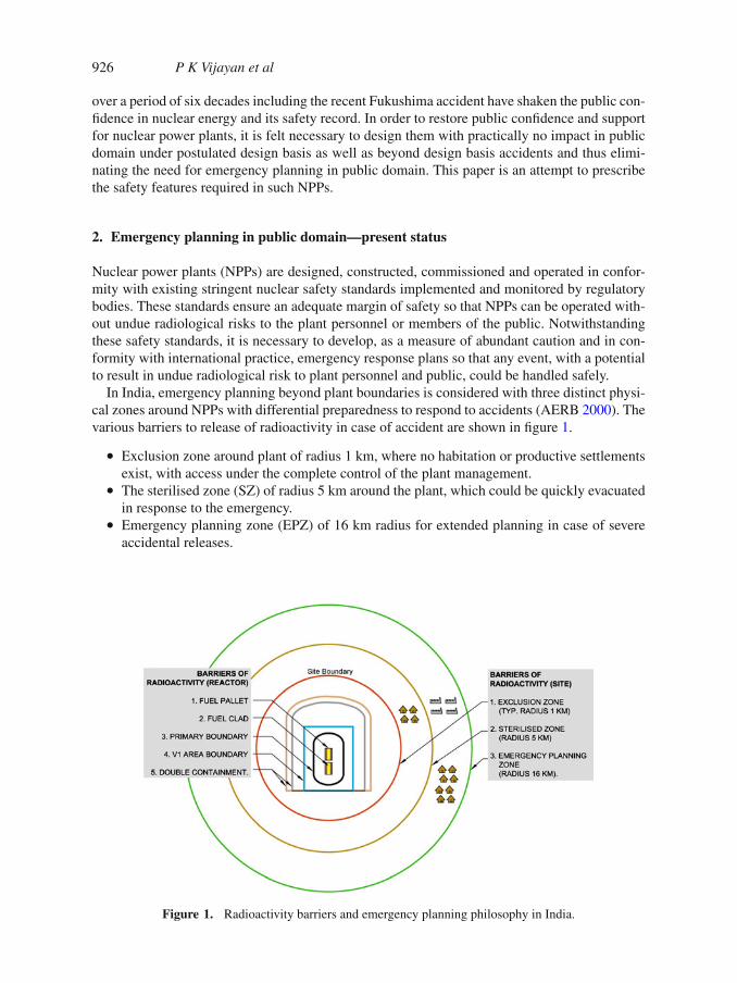
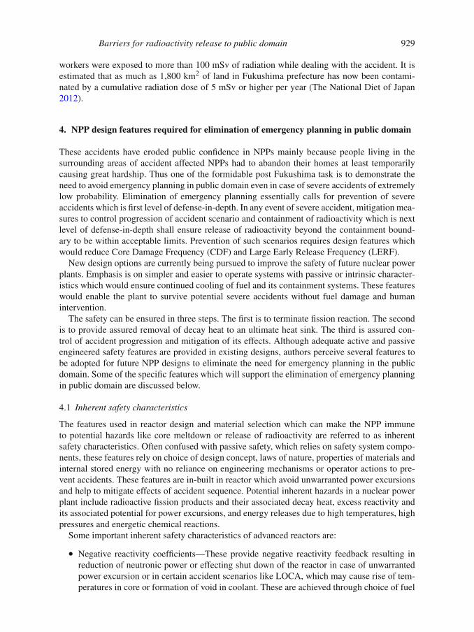
In India, emergency planning beyond plant boundaries is considered with three distinct physi-cal zones around NPPs with differential preparedness to respond to accidents (AERB 2000). Thevarious barriers to release of radioactivity in case of accident are shown in figure 1.
• Exclusion zone around plant of radius 1 km, where no habitation or productive settlementsexist, with access under the complete control of the plant management.
• The sterilised zone (SZ) of radius 5 km around the plant, which could be quickly evacuatedin response to the emergency.
• Emergency planning zone (EPZ) of 16 km radius for extended planning in case of severeaccidental releases.
Figure 1. Radioactivity barriers and emergency planning philosophy in India.
Barriers for radioactivity release to public domain 927
An accidental release of radioactivity extending beyond the plant but confined to the siteboundary (exclusion zone) constitutes a site emergency. However, very low probability accidentslike Loss of Coolant Accident (LOCA) plus failure of both the reactor shutdown systems andcontainment impairment may result into an off-site emergency releasing radioactivity in publicdomain. In these cases, the radiological consequences of an emergency situation originating fromNPP are likely to extend beyond the site boundary and into the public domain into SZ and EPZ.
At this stage, it is desirable to review the major NPP accidents which required implementationof emergency planning measures in public domain.
3. Brief description of major NPP accidents
3.1 Three Mile Island accident
The accident and partial meltdown at the Three Mile Island (TMI) NPP Unit-2 near Middletown,Pennsylvania, on March 28, 1979, was caused by a combination of equipment malfunctions,design related problems and operator errors. TMI-2 experienced failure of main feed water pumpon non-nuclear secondary side, preventing steam generators from heat removal. Following thisfailure, reactor was shut down as intended. However, pressure relief valve opened due to higherpressure as expected but remained stuck open for about two hours resulting in Small BreakLOCA. Failure of instrumentation made operator unaware of this and series of operator actionsworsened the situation, ultimately, resulting in partial core meltdown. Due to the metal-waterreaction, a hydrogen ‘bubble’ formed in the reactor pressure vessel, leaked through the stuckopen relief valve and broken rupture disk, eventually accumulating at the top of the containmentbuilding. The hydrogen—oxygen mixture had deflagration 10 hours after the onset of the acci-dent. Fortunately, the deflagration-generated pressure spike did not exceed 2 bar (gauge pressure)and prevented containment failure. There was no other large-scale physical damage to the plant.Most of the radioactivity was contained in the plant. Nearly a million gallons of contaminatedwater ended up in the basement of the reactor building and in tanks in auxiliary building. Thisaccident did not result in breach of the walls of the reactor pressure vessel and of the contain-ment building which avoided release of radioactivity to the environment (Nuclear RegulatoryCommission, USA 1980). However, public memory of the uncertainty following the meltdownwas long lasting. In an atmosphere of uncertainty and anxiety, Pennsylvanian Governor afterconsulting Nuclear Regulatory Commission (NRC) advised for evacuation of pregnant womenand pre-school age children within 5-mile radius of the plant. Amongst panic, people living nearthe plant also voluntarily evacuated.
Radiation exposures from the TMI accident were a small fraction of the average annual radia-tion exposure from natural background radiation (GPU nuclear corporation 1986). Nevertheless,this accident resulted in sweeping changes in safety philosophy in reactor design and operation,reinforcing the concepts of defense-in-depth and safety culture.
3.2 Chernobyl accident
On 26 April 1986, an accidental explosion during a safety test and fires at the Chernobyl NPPunit-4 in Ukraine caused the largest uncontrolled radioactivity release in the history of the civilnuclear industry. Over the next 10 days, large quantities of radioactive iodine and cesium werereleased into the atmosphere. Most of this material was deposited near the installation, but lightermaterial was carried by wind currents over Belarus, the Russian Federation and Ukraine and, tosome extent, over parts of Europe.
928 P K Vijayan et al
As an initial response, obligatory evacuation of population within a zone of 30 km radius wascarried out. Afterwards, evacuation was extended based on spread of contamination. Restrictionson land-use were implemented and controls of radioactive contamination in foodstuffs and otherproduce strengthened.
About 1000 emergency workers and personnel that were on-site during the first few days ofthe accident received the highest doses of radiation. About 28 emergency workers died fromAcute Radiation Syndrome (ARS) and two died from industrial injuries. Nineteen more diedduring 1987-2004 whose deaths may be related to radiation exposure (The Chernobyl Forum,2006). However, more than 348,000 people have been resettled away from the most severelycontaminated areas, some were evacuated immediately after the accident, and others were reset-tled several years later. The average effective doses among 530,000 recovery operation workerswas 120 milli-Sieverts (mSv); among 115,000 evacuees, 30 mSv; among residents of contam-inated areas, 9 mSv (during the first two decades after the accident); and among residents ofother European countries, less than 1 mSv (in the first year after the accident). In more distantcountries, doses of exposure decreased progressively in subsequent years. Since such doses arebelow the global average annual dose of 2.4 mSv from natural background radiation, the radia-tion exposures in countries distant from Chernobyl are considered to be of little radiological andpublic health significance (UNDP and UNICEF 2002).
Even in countries beyond those most directly affected, Chernobyl triggered questions con-cerning the safety of crops, milk, food, and water; the effects of radiation exposure on differentpopulation groups; and the kind of preventive measures that were to be put in place. Inmany countries, the accident prompted important political discussions regarding the use ofnuclear energy and national energy policies. Chernobyl also underscored the critical need forinternational coordination and cooperation related to environmental hazards.
3.3 Fukushima accident
Tohoku earthquake, which occurred on Friday, March 11, 2011, on the east coast of northernJapan, the fourth largest earthquake in recorded history, was followed by tsunami hitting thecoast with a delay of 40 minutes. Along the entire east coast of Japan, at least 15,700 people werekilled, 4,650 went missing, 5,300 were injured, and 131,000 were displaced (ANS 2012). Thenuclear power plants (NPPs) at the Fukushima Daiichi, Fukushima Daini, Higashidori, Onagawa,and Tokai Daini were affected. Following the earthquake, all operating reactors were shutdownbased on seismic instrumentation signal. The earthquake also resulted in loss of off-site power.Emergency systems were activated including diesel generators for decay heat removal and otherfunctions. However, tsunami of ∼15 m height which hit the coast after 40 minutes, caused a lossof on-site power and emergency battery power at the Fukushima Daiichi NPP, leaving it with-out any emergency coolant injection capability resulting in degraded core cooling. This resultedin possible exposure of core and formation of hydrogen due to metal water reaction and subse-quent pressurization of containment. The operators tried to respond with containment venting,failure of which resulted in hydrogen explosion and containment failure. The resultant dam-age to containment caused release of radioactive materials to the region surrounding the NPP.Following this, initially a 3 km radius area was evacuated and later extended to 10 km and sub-sequently to 20 km radius with a 30 km radius shelter zone. Measurable radioactive materials,mainly iodine-131 (131I), cesium-134 (134Cs), and cesium-137 (137Cs), were identified in publicwater supplies as well as in certain land areas. However, after initial peaking, the concentrationof these radio-nuclides reduced significantly. About 1,46,520 people were evacuated in responseto the accident, though evacuation appears to be made on an ad-hoc manner. An estimated 167
Barriers for radioactivity release to public domain 929
workers were exposed to more than 100 mSv of radiation while dealing with the accident. It isestimated that as much as 1,800 km2 of land in Fukushima prefecture has now been contami-nated by a cumulative radiation dose of 5 mSv or higher per year (The National Diet of Japan2012).
4. NPP design features required for elimination of emergency planning in public domain
These accidents have eroded public confidence in NPPs mainly because people living in thesurrounding areas of accident affected NPPs had to abandon their homes at least temporarilycausing great hardship. Thus one of the formidable post Fukushima task is to demonstrate theneed to avoid emergency planning in public domain even in case of severe accidents of extremelylow probability. Elimination of emergency planning essentially calls for prevention of severeaccidents which is first level of defense-in-depth. In any event of severe accident, mitigation mea-sures to control progression of accident scenario and containment of radioactivity which is nextlevel of defense-in-depth shall ensure release of radioactivity beyond the containment bound-ary to be within acceptable limits. Prevention of such scenarios requires design features whichwould reduce Core Damage Frequency (CDF) and Large Early Release Frequency (LERF).
New design options are currently being pursued to improve the safety of future nuclear powerplants. Emphasis is on simpler and easier to operate systems with passive or intrinsic character-istics which would ensure continued cooling of fuel and its containment systems. These featureswould enable the plant to survive potential severe accidents without fuel damage and humanintervention.
The safety can be ensured in three steps. The first is to terminate fission reaction. The secondis to provide assured removal of decay heat to an ultimate heat sink. The third is assured con-trol of accident progression and mitigation of its effects. Although adequate active and passiveengineered safety features are provided in existing designs, authors perceive several features tobe adopted for future NPP designs to eliminate the need for emergency planning in the publicdomain. Some of the specific features which will support the elimination of emergency planningin public domain are discussed below.
4.1 Inherent safety characteristics
The features used in reactor design and material selection which can make the NPP immuneto potential hazards like core meltdown or release of radioactivity are referred to as inherentsafety characteristics. Often confused with passive safety, which relies on safety system compo-nents, these features rely on choice of design concept, laws of nature, properties of materials andinternal stored energy with no reliance on engineering mechanisms or operator actions to pre-vent accidents. These features are in-built in reactor which avoid unwarranted power excursionsand help to mitigate effects of accident sequence. Potential inherent hazards in a nuclear powerplant include radioactive fission products and their associated decay heat, excess reactivity andits associated potential for power excursions, and energy releases due to high temperatures, highpressures and energetic chemical reactions.
Some important inherent safety characteristics of advanced reactors are:
• Negative reactivity coefficients—These provide negative reactivity feedback resulting inreduction of neutronic power or effecting shut down of the reactor in case of unwarrantedpower excursion or in certain accident scenarios like LOCA, which may cause rise of tem-peratures in core or formation of void in coolant. These are achieved through choice of fuel
930 P K Vijayan et al
and in-core materials and design of core configuration. These are negative void coefficientof reactivity and negative temperature coefficient of reactivity.
• Low power density• Low excess reactivity in core limiting unwarranted power rise• Proper selection of materials—Fuel matrix with high specific heat, high thermal conductiv-
ity and high fission gas retention capacity; fuel clad materials with resistance to corrosion,no hydrogen generation by metal water reaction and oxidation; fuel coatings; eliminationof potentially hazardous materials like graphite.
Inherent safety characteristics make NPP more ‘forgiving’ or ‘tolerant’. When an inherentsafety feature alone is not capable of accident prevention or mitigation beyond certain limit,safety systems, structures or components are provided in NPP to prevent, mitigate, or containpotential accidents. Although an objective in their design is to make them highly reliable, theyremain in principle subject to failure (however low the probability of such failure), unlike inher-ent safety characteristics. Stated another way, an inherent safety feature represents conclusive,or deterministic safety, not probabilistic safety and are not subject to failure.
4.2 Incorporation of passive safety systems in reactor design
Passive safety systems operate based on natural physical laws such as gravity, buoyancy, etc. andderive their energy for operation from the system itself, thus they do not require external sourceof energy or operator actuation, bringing the reactor to safe condition by passive means. Somepotential causes of failure of active systems, such as lack of human action or power failure, donot exist when passive safety is provided. Some of the examples of application of passive safetysystems in future designs which can avoid occurrence of severe accident are described below.
4.2a Passive shutdown systems: Safe shut down of the reactor is important safety functionwhich must be ensured to avoid and mitigate accidents of severe nature. Most of the shutdownsystems rely on active components like instrumentation signals and power signals although madefail safe and partially passive. For shutdown of reactor under operating transients and DBAs,shutdown philosophy in line with defense-in-depth concept is widely used in almost all recentreactors, and shall remain in application in advanced reactors. This design includes at least twoseparate, independent, and diverse means of shutting down the reactor. At least one means ofshutdown is independently capable of rendering the reactor subcritical from normal operation,and in DBAs, and maintaining the reactor subcritical by an adequate margin and with high reli-ability for even the most reactive conditions of the core. To improve reliability, stored energyis used in shutdown actuation. However, wired systems are vulnerable to insider threats. Pas-sive means of reactor shutdown including instrumentation and actuation of such system will beimportant to combat insider threat.
Insider threat is a real possibility in these days due to the immense potential of terrorist threat,in which an insider with highly sophisticated knowledge of plant dynamics may purposefullycreate scenarios leading to severe accidents by compromising safety systems. In the case ofmalevolent acts by an insider which can be purposefully detrimental to safety of reactor andinability of plant operators to manage the events and their consequences, for a significantly longtime, reactor should be capable of passively shutting down itself and maintaining coolabilitywithout regard to operator action. Examples of such systems are the density lock concept inthe Process Inherent Ultimate Safety (PIUS) reactor (Boyack et al 1995) and Passive Poison
Barriers for radioactivity release to public domain 931
Injection System (PPIS) in Advanced Heavy Water Reactor (AHWR) which can passively shutdown the reactor even with failure of wired shutdown systems.
4.3 Passive ultimate heat sink that cannot be lost
Unlike conventional power plants, nuclear power plant core keeps on generating heat even afterreactor shut down due to decay of fission products although in diminishing fraction of originalfull power of the core. Assured removal of decay heat after reactor shutdown is principal safetyconcern in nuclear reactors.
4.3a Passive decay heat removal: For any NPP, the main objective of safety is to provideassured removal of decay heat to an ultimate heat sink after safe shutdown of the reactor. Theconventional decay heat removal systems using water or air as cooling medium are essentiallyactive systems whose availability cannot be ensured in the event of a Fukushima type long termStation Black Out (SBO) i.e., loss of offsite, onsite and emergency power supply. Passive decayheat removal for extended periods of SBO is essential feature for ensuring safety of reactor.
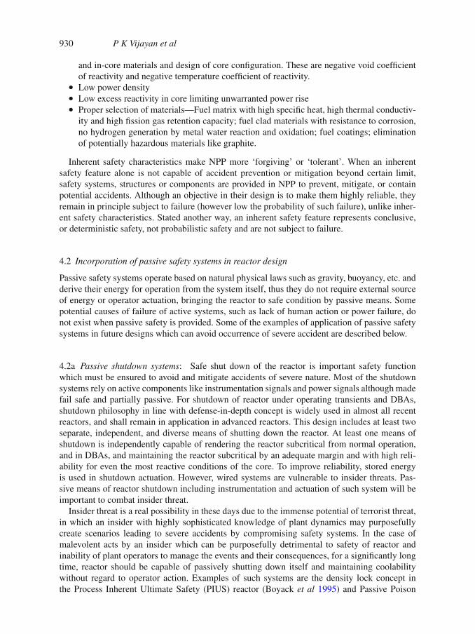
Present reactor designs qualify for core coolability for finite period of time in the event of aStation Black Out (SBO) depending on design feature and regulatory requirements. The first gen-eration of LWRs provided emergency coolant injection and decay heat removal by active means,while advanced LWR concepts use passive means to accomplish these functions. The proposedpassive systems for advanced reactors generally use a pool with immersed heat exchangers. Suchsystems can either be on the steam generator side or on the reactor side as shown in figure 2.They all employ natural circulation for transport of decay heat from core to pool.
Figure 2. Limited mission time concepts for passive decay heat removal (a) natural circulation in pri-mary circuit as well as steam generator connected to water tank, (b) natural circulation in primary circuitconnected to water tank.
932 P K Vijayan et al
However, these systems can sustain decay heat removal for finite time depending on the inven-tory of water in the pool making them unsuitable for extended SBOs. Another limitation is thatthe water can leak out in case of failure on the pool side. Therefore, ultimate heat sink whichcannot be lost will be an important design feature to eliminate emergency planning in publicdomain. Air is an ideal infinite heat sink for decay heat removal which can ensure core coolabilityfor infinite time as it cannot be lost unlike stored water.
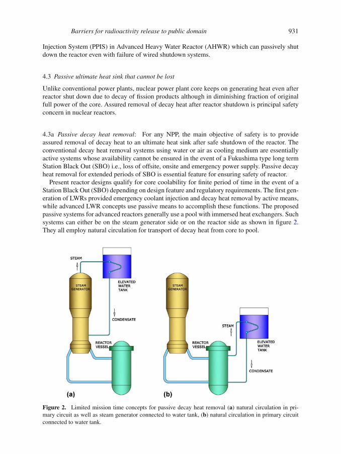
Typical example is Safety Grade Decay Heat Removal System (SGDHRS) employed inPrototype Fast Breeder Reactor (PFBR) under construction at Kalpakkam, India. Figure 3demonstrates the SGDHRS. In PFBR, main reactor vessel houses the reactor core inside a liquidsodium pool. Under reactor shutdown condition, decay heat from the core is transferred to liq-uid sodium pool. This heat is transferred to sodium to air heat exchanger located outside reactorbuilding through an intermediate sodium loop. The sodium to air heat exchanger is located in atall stack with manual dampers at bottom. Sodium flow in main vessel pool, intermediate sodiumloop and air flow in stack is maintained by natural circulation. Under prolonged station black outconditions, this system can maintain temperatures of critical structures within prescribed limitswithout external power supply. It is a passive system except for the air dampers on the air-side(Mathews et al 2008).
The completely passive operation of the decay heat removal system requires components likevalves and dampers to act by passive means. The AHWR, being developed at BARC, Indiaemploys passive valves and one way rupture disks for decay heat removal and emergency coolantinjection. AHWR is a 300 MWe, vertical, pressure tube type reactor cooled by boiling light water
Figure 3. Safety grade decay heat removal system of PFBR.
Barriers for radioactivity release to public domain 933
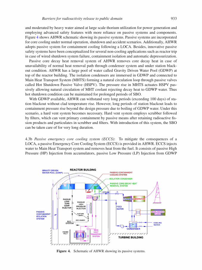
and moderated by heavy water aimed at large scale thorium utilization for power generation andemploying advanced safety features with more reliance on passive systems and components.Figure 4 shows AHWR schematic showing its passive systems. Passive systems are incorporatedfor core cooling under normal operation, shutdown and accident scenarios. Additionally, AHWRadopts passive system for containment cooling following a LOCA. Besides, innovative passivesafety systems have been conceptualized for several non-cooling applications such as reactor tripin case of wired shutdown system failure, containment isolation and automatic depressurization.
Passive core decay heat removal system of AHWR removes core decay heat in case ofunavailability of normal heat removal path through condenser system and under station black-out condition. AHWR has a large pool of water called Gravity Driven Water Pool (GDWP) attop of the reactor building. The isolation condensers are immersed in GDWP and connected toMain Heat Transport System (MHTS) forming a natural circulation loop through passive valvescalled Hot Shutdown Passive Valve (HSPV). The pressure rise in MHTS actuates HSPV pas-sively allowing natural circulation of MHT coolant rejecting decay heat to GDWP water. Thushot shutdown condition can be maintained for prolonged periods of SBO.
With GDWP available, AHWR can withstand very long periods (exceeding 100 days) of sta-tion blackout without clad temperature rise. However, long periods of station blackout leads tocontainment pressure rise beyond the design pressure due to boiling of GDWP water. Under thisscenario, a hard vent system becomes necessary. Hard vent system employs scrubber followedby filters, which can vent primary containment by passive means after retaining radioactive fis-sion products and particulates in scrubber and filters. With introduction of this system, the SBOcan be taken care of for very long duration.
4.3b Passive emergency core cooling system (ECCS): To mitigate the consequences of aLOCA, a passive Emergency Core Cooling System (ECCS) is provided in AHWR. ECCS injectswater to Main Heat Transport system and removes heat from the fuel. It consists of passive HighPressure (HP) Injection from accumulators, passive Low Pressure (LP) Injection from GDWP
Figure 4. Schematic of AHWR showing its passive systems.
934 P K Vijayan et al
and active Long Term re-circulation. To achieve complete passive operation, One Way RuptureDiscs (OWRD) have been incorporated downstream of accumulators and GDWP. The OWRDfails at low differential pressure in the forward direction, but withstand the high differentialpressure in the reverse direction. Direct injection of emergency coolant into the fuel bundle isanother feature of AHWR, which ensures cooling water injection where it is most needed withleast time delay.
4.3c Decay heat removal in case of failure of ECCS or after mission time of ECCS: Certainaccident scenarios like failure of ECCS coupled with loss of ultimate heat sink can be dealtwith by submergence of reactor vessel/primary system piping with cooling water. These con-cepts rely on heat being transferred from core by free convection. Pool evaporation with vaporcondensation on containment walls will be source of heat removal. Vapor leaving the pool willcondense on the containment walls cooled by air circulation on outer surface of containment.
In AHWR, about 6000 m3 of the GDWP water gets injected into the core following a LOCAand is adequate to provide cooling for three days. Since all the primary piping is located inV1 volume, the discharging primary coolant from the break accumulates in V1 eventually sub-merging the bare primary system piping providing adequate passive cooling for a long time(> 100 days) by the ‘boil-off’ mechanism. The total inventory in the MHTS and ECCS can sub-merge more than one-third of the tail pipe tower. An interesting feature of LOCA in AHWR isthat the discharging coolant is not lost, but is passively relocated into the tail pipe tower whereit continues to cool the MHTS. In other words LOCA eventually leads to ROPS (Relocation OfPassive Sink) without impairing cooling.
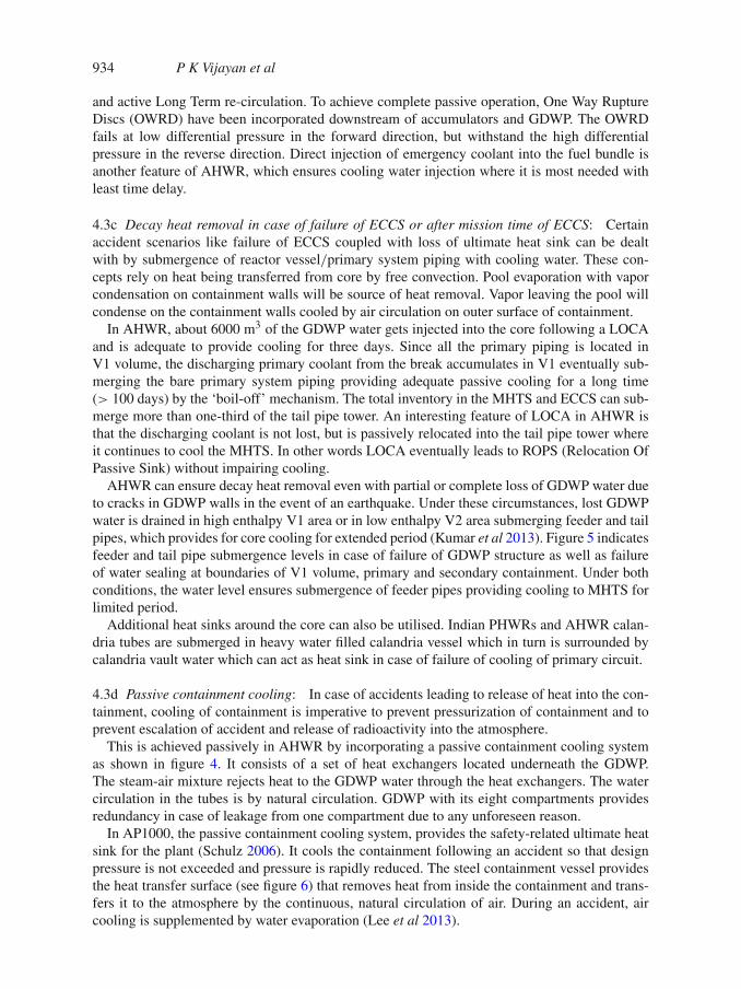
AHWR can ensure decay heat removal even with partial or complete loss of GDWP water dueto cracks in GDWP walls in the event of an earthquake. Under these circumstances, lost GDWPwater is drained in high enthalpy V1 area or in low enthalpy V2 area submerging feeder and tailpipes, which provides for core cooling for extended period (Kumar et al 2013). Figure 5 indicatesfeeder and tail pipe submergence levels in case of failure of GDWP structure as well as failureof water sealing at boundaries of V1 volume, primary and secondary containment. Under bothconditions, the water level ensures submergence of feeder pipes providing cooling to MHTS forlimited period.
Additional heat sinks around the core can also be utilised. Indian PHWRs and AHWR calan-dria tubes are submerged in heavy water filled calandria vessel which in turn is surrounded bycalandria vault water which can act as heat sink in case of failure of cooling of primary circuit.
4.3d Passive containment cooling: In case of accidents leading to release of heat into the con-tainment, cooling of containment is imperative to prevent pressurization of containment and toprevent escalation of accident and release of radioactivity into the atmosphere.
This is achieved passively in AHWR by incorporating a passive containment cooling systemas shown in figure 4. It consists of a set of heat exchangers located underneath the GDWP.The steam-air mixture rejects heat to the GDWP water through the heat exchangers. The watercirculation in the tubes is by natural circulation. GDWP with its eight compartments providesredundancy in case of leakage from one compartment due to any unforeseen reason.
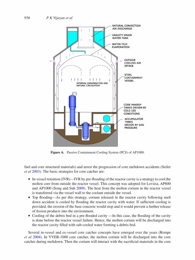
In AP1000, the passive containment cooling system, provides the safety-related ultimate heatsink for the plant (Schulz 2006). It cools the containment following an accident so that designpressure is not exceeded and pressure is rapidly reduced. The steel containment vessel providesthe heat transfer surface (see figure 6) that removes heat from inside the containment and trans-fers it to the atmosphere by the continuous, natural circulation of air. During an accident, aircooling is supplemented by water evaporation (Lee et al 2013).
Barriers for radioactivity release to public domain 935
Figure 5. Feeder pipe submergence in AHWR in extreme case of failure of GDWP structure and watersealing of primary containment assures extended cooling.
4.4 Managing decay heat in post severe accident
Decay heat removal from uncovered cores should also be considered in case of severe accidents.In defense-in-depth philosophy, several barriers to radioactivity release like fuel, clad, primarypressure boundary and primary containment are provided. However, same barriers present dif-ficulties in transferring decay heat from core to atmosphere, needing a balance between thesetwo requirements. Decay heat removal from the uncovered core in case of severe accident is byradiation and convection in steam/air mixture, and conduction. The heat transfer through solidcores would require exploring new core configurations like annular fuel rod clusters and devel-opment of core components having higher cladding temperature, higher conductivity and higherheat storage capacity.
4.4a Passive core catcher design that prevents re-criticality and ensure cool down: Eventhough all nuclear power plant designs comply with regulatory requirements, core melt acci-dents can occur in case of low probability events such as extreme natural events coupled withone or more Beyond Design Basis Events (BDBE) as that happened in case of Fukushima. Thepurpose of a core catcher is to safely contain and cool the corium (a molten mixture of nuclear
936 P K Vijayan et al
Figure 6. Passive Containment Cooling System (PCS) of AP1000.
fuel and core structural materials) and arrest the progression of core meltdown accidents (Seileret al 2003). The basic strategies for core catcher are:
• In-vessel retention (IVR)—IVR by pre-flooding of the reactor cavity is a strategy to cool themolten core from outside the reactor vessel. This concept was adopted for Loviisa, AP600and AP1000 (Song and Suh 2009). The heat from the molten corium in the reactor vesselis transferred via the vessel wall to the coolant outside the vessel.
• Top flooding—As per this strategy, corium released in the reactor cavity following meltdown accident is cooled by flooding the reactor cavity with water. If sufficient cooling isprovided, the erosion of the base concrete would stop and it would prevent a further releaseof fission products into the environment.
• Cooling of the debris bed in a pre-flooded cavity —In this case, the flooding of the cavityis done before the reactor vessel failure. Hence, the molten corium will be discharged intothe reactor cavity filled with sub-cooled water forming a debris bed.
Several in-vessel and ex-vessel core catcher concepts have emerged over the years (Rempeet al 2004). In VVER-1000 core catcher, the molten corium will be discharged into the corecatcher during meltdown. Then the corium will interact with the sacrificial materials in the core
Barriers for radioactivity release to public domain 937
catcher reducing volumetric decay heat density and reducing overall temperature of the moltenmass. The boiling of the water outside the core catcher will remove the decay heat from themolten core. In EPR, corium is collected in a reactor pit, conditioned with sacrificial concreteand subsequently spread onto a large surface. Water flow channel is provided along the surfaceof the reactor pit to cool the mixture of corium and sacrificial material. In addition, water isflooded over the mixture (Song and Suh 2009).
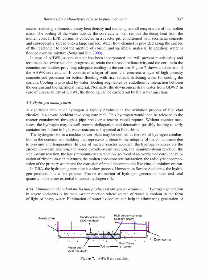
In case of AHWR, a core catcher has been incorporated that will prevent re-criticality andterminate the severe accident progression, retain the released radioactivity and the corium in thecontainment besides providing adequate cooling to the corium. Figure 7 shows a schematic ofthe AHWR core catcher. It consists of a layer of sacrificial concrete, a layer of high porosityconcrete and provision for bottom flooding with riser tubes distributing water for cooling thecorium. Cooling is provided by water flooding augmented by endothermic interaction betweenthe corium and the sacrificial material. Normally, the downcomers draw water from GDWP. Incase of unavailability of GDWP, the flooding can be carried out by fire water injection.
4.5 Hydrogen management
A significant amount of hydrogen is rapidly produced in the oxidation process of fuel cladzircaloy in a severe accident involving core melt. This hydrogen would then be released to thereactor containment through a pipe break or a reactor vessel rupture. Without counter mea-sures, the hydrogen may as well prompt deflagration and detonation possibly leading to earlycontainment failure in light water reactors as happened at Fukushima.
The hydrogen risk in a nuclear power plant may be defined as the risk of hydrogen combus-tion in the containment building that represents a threat to the integrity of the containment dueto pressure and temperature. In case of nuclear reactor accident, the hydrogen sources are thezirconium–steam reaction, the boron carbide–steam reaction, the uranium–steam reaction, thesteel–steam reaction, the late zirconium–steam reaction (re-flood of an overheated core), the relo-cation of zirconium-rich mixtures, the molten core–concrete interaction, the radiolytic decompo-sition of the primary water, and the corrosion of metallic compounds like zinc, aluminium or iron.
In DBA, the hydrogen generation is a slow process. However, in Severe Accidents, the hydro-gen production is a fast process. Precise estimation of hydrogen generation rates and totalquantity is therefore essential to assess hydrogen risk.
4.5a Elimination of coolant media that produces hydrogen by oxidation: Hydrogen generationin severe accidents is by metal–water reaction where source of water is coolant in the formof light or heavy water. Elimination of water as coolant can help in eliminating generation of
Sacrificial Concrete(300 mm depth)
High porosity concrete(300 mm depth)
Water pool(500 mm depth)
Riser Tubes(φ 100mm) 7.4 m
Downcomer
Downcomer
Figure 7. AHWR core catcher.
938 P K Vijayan et al
hydrogen. Advanced reactors using high temperature molten metal/molten salts as coolant havean inherent advantage in this regard due to absence of water in direct contact with fuel clad.However, water cooled reactors would need to address this issue to avoid hydrogen risk.
4.5b Elimination of fuel clad that produces hydrogen by oxidation: A cladding material moreresistant to high temperature oxidation can eliminate hydrogen risk. For future reactors operat-ing with fast neutron spectrum, higher temperatures, coolants like sodium, lead, molten salts,etc. and higher burnups ranging up to ∼200 GWd/t, development of new clad materials arebeing pursued. Several materials, such as ferritic or martensitic stainless steels, oxide disper-sion strengthened (ODS) alloys, nickel based super alloys, refractory metals and materials (SiCand ZrC), have been suggested as candidate fuel cladding materials. Eventually, these may findapplications in water cooled reactors as well.
Silicon carbide which is being considered as fuel clad material has several major advantagesover Zr-based clad material. These include:
• Lower absorption of thermal neutrons.• Little corrosion and no hydrogen pickup during normal operation, thus enabling a major
increase in fuel life and energy content.• Strength retention and low corrosion rate at elevated temperatures.• Much slower degradation in a severe accident scenario; no meltdown, low corrosion rate,
less/no hydrogen generation.
Though SiC fibres start off at a somewhat lower strength than Zr-based cladding, they retaintheir strength at very high temperatures. This provides a significant advantage in maintainingcoolable fuel geometry during beyond design basis accidents. An additional advantage is theresistance to steam and air oxidation. Testing has shown that while Zr cladding has up to 17 %oxidation after 400 s in 1200 ◦C steam, SiC samples have negligible mass loss even after 800 s at1200 ◦C. Also, since SiC is a ceramic, it will not balloon as Zr alloy cladding until it reaches itsfailure point. The failure temperature for SiC cladding is estimated to be greater than 2000 ◦C.Equally important in nuclear applications is the favourable response of SiC to radiation fields.While thermal conductivity decreases after irradiation, it remains comparable to zirconium cladwithout significant decrease in strength (Hallstadius et al 2012).
4.5c Fast recombination of hydrogen: Passive Autocatalytic Recombiner (PAR) has emergedas a hydrogen control device in modern NPPs. PARs are self-starting, self-feeding and do notrequire power for operation. They instead use a platinum and/or palladium catalyst to recombinehydrogen and oxygen gases into water vapor upon contact with the catalyst. The heat producedduring recombination process creates strong buoyancy effects which increase the influx of sur-rounding gases to the PAR inlet. These natural convective flow currents tend to promote mixingof combustible gases preventing formation of hydrogen pockets in the reactor containment.
The chemical reaction between hydrogen and oxygen to form water is a strongly exothermicreaction [H2 + (1/2)O2 → H2O + 238 kJ/mol] that starts only after overcoming a high activa-tion energy. The activation energy can be significantly reduced by the use of catalysts (platinum,palladium), so that the reaction can start at low temperatures without propagation to the sur-rounding atmosphere. The mechanism for catalytic oxidation of hydrogen on metals is that ofLangmuir–Hinchelwood with two steps that are the diffusion of the reactants, and the reaction
Barriers for radioactivity release to public domain 939
of absorbed reactants on the catalyst. A catalytic recombiner comes into action spontaneouslyas soon as the hydrogen concentration begins to increase in the reactor building atmosphere(Park et al 2011). Catalytic recombiners can be used currently to protect nuclear power plantsagainst hydrogen risk.
At the moment, the catalytic recombiners are recognized by many nuclear safety authoritiesand adopted by nuclear power plant utilities all over the world. PARs are used in NPPs in Europe,Canada and USA. Following the Fukushima accident, a decision to back-fit all Indian NPPs withPAR was taken and is being implemented.
4.5d Pre-inerting of containment: Another concept for the hydrogen hazard mitigation inexisting nuclear power plants is pre-inerting which is employed in boiling water reactorsin Germany, Japan, USA and Sweden (Bachellerie et al 2003). Purging management is used inmany US BWRs which utilize nitrogen inerting as the primary defense against hydrogen ignition(Dallman et al 1988).
4.5e Controlled release of hydrogen/hardened vent: Severe accidents can produce large quan-tities of hydrogen in short time beyond the recombination capabilities of PARs resulting inserious hydrogen risk. Timely venting of the containment is essential for hydrogen managementas well as to avoid containment pressurization. A ‘hardened vent’ is a separate vent pipe designedto withstand higher loads during an accident and routed to an elevated point outside the reactorbuilding. These vents are designed to withstand the pressure and temperature of the steam gen-erated early in an accident. The vents must also withstand possible fires and small explosions ifthey are used to release hydrogen later in an accident. A hardened vent system usually incorpo-rates a set of isolation valves designed to prevent an unintended release of fission products intothe environment. Various reactors in operation include features that allow operators to vent gasesfrom the primary containment in an emergency. Hard vents have been installed in many Mark Icontainments in US, following NRC recommendation of ‘Installation of hardened Wetwell vent’in 1989. However, most designs rely on remote/manual electrical operation.
Importance of such hard vent can be established looking at the inability of venting and sub-sequent hydrogen explosion at Fukushima. Fukushima Dai-ichi Units 1, 2, 3, and 4 requiredactuation of active valves and instrumentation for venting reactor building to stack which couldnot be achieved due to loss of AC power. The operator’s inability to vent the containment mostlikely resulted in the leakage of hydrogen gas into the reactor building, precipitating explosionsthat blew away the containment roof. Venting systems are presently designed with active compo-nents like instrumentation, AC power and control logics to address such scenarios. Alternatively,a reliable venting capability can be provided through a passive containment venting design,such as rupture disks with independent isolation valves. Such passive vents provide fail-safecontainment pressure relief with no operator action or power supplies.
Significant reduction in the release of radioactive airborne contamination can be achievedby the scrubbing action of pool water along with filters to arrest particulates discharging toatmosphere. Many European countries like France, Germany and Sweden use high-capacity filtersystems, intended to limit the contamination of the environment to 0.1 percent of the reactor coreinventory of radioactive material in the event of a severe accident (Leyse 2012).
Hardened vents with passive features and high capacity filtering will be the way ahead forNPPs for ultimate mitigation of hydrogen risk and for protection of public from radioactivityrelease. Following the Fukushima accident, a decision to back-fit all Indian NPPs with hard vent
940 P K Vijayan et al
was taken and is being implemented. AHWR will also employ PAR and hardened vents forhydrogen mitigation.
4.6 Fire proof containment and physical protection
Following 9/11 terrorist incident, several measures were identified for physical protection andfire safety. With present scenario on security of nuclear installations, perhaps the most importantaspect of gaining public acceptance is addressing the need for enhanced security through nuclearsafety as design objective.
A terrorist attack is now being considered as Design Basis Threat (DBT) with objective assess-ment of demographic security needs and regulatory framework for safety against such externalmanmade threats is being continuously modified. However, apart from security protocols, NPPsneed to incorporate several design features to ensure that no unacceptable radiological impactoutside the plant boundary happens even with such attack.
A robust containment structure to protect internal systems against external threats is importantaspect in this regard. Such containment shall be capable of safety against missile, aircraft impact,sabotage and fire for extended periods.
These threats can be categorized under following:
(i) External threat—physical, cyber, biochemical, and other terrorist threats, 26/11Mumbai type multiple coordinated attack, 9/11 type aircraft/missile/explosive attack, theftor diversion of nuclear material.
(ii) Internal threat–attack from several persons employed at the facility possibly with a sophis-ticated knowledge of facility operations.
Even before the recent attacks, nuclear power plants were designed to protect public healthand safety. The plants achieved this through their robust containment buildings, redundant safetysystems, highly trained operators and maintenance staff, stringent security plans, and armedsecurity personnel. In future reactors, continuous evaluation and improvement of safety andsecurity philosophy will be essential as these threats are inherently dynamic and intelligence isoften limited to predict the threat.
However, best safety against such threats lies in design of the NPP. Passive and inherent safetyfeatures and effective implementation of safety philosophy in future reactors can provide largepart of the solution.
It is clear that in 9/11 type attacks, containment will provide most important physical barrierfor mitigation. For example, in EPR Finland design, the reactor building as well as the sur-rounding auxiliary buildings housing safety related equipment are structurally strengthened tothe extent needed for surviving the impact of a large commercial aircraft. Some design mea-sures, provided to deal with specific external events, call for additional protective features inplant layout and design. In EPR and SWR 1000, for example, aircraft crash protection mea-sures have been implemented through attention being paid to plant layout, low vertical profile ofcontainment, and additional robustness of protective external structures (IAEA-TECDOC-14872006).
5. Proposed future development
Few development aspects to achieve the goal of elimination of emergency planning are brieflylisted below.
Barriers for radioactivity release to public domain 941
5.1 Station blackout
Extended SBO with loss of infrastructure in and around NPP will be a design issue for futurereactors. Developing systems in NPPs which can rely on providing cooling capabilities forinfinite time in case of extreme natural events with the help of ultimate heat sink that cannotbe lost would be essential. The following mitigation capabilities are required for extended SBOsituations:
• Maintaining highly reliable onsite electric power systems/instrumentation.• Additional sources of coolant water for the reactor and steam generators.• Passive methods of depressurization of primary system and feed water system.• Passive methods to cool the reactor core and minimize releases of radioactive materials
from containment.
5.2 Hydrogen management
Assessing and addressing hydrogen risk of the plant will require study of advanced NPP designsand their characteristics, selection of accident sequences, assessment of the hydrogen sources aswell as the steam sources, follow-up and modelling of the hydrogen/oxygen/inert gas distribu-tion, and evaluation of the hydrogen combustion risk based on factors like response of ventingand inerting systems. Scrubbing or filtration systems would be needed to reduce release of activ-ity in case of venting. Development of effective PAR systems can greatly reduce hydrogen risk,however analyses of different accident progression scenarios is required.
5.3 Fuel cladding development
There are many practical issues associated with introducing SiC based fuel cladding today. Theseinclude manufacturing technology, large-scale manufacturing costs, fundamental understand-ing of the composite technology, and licensing. Though monolithic SiC tubes are very strong,they are brittle. A cost-effective large-scale manufacturing technique for SiC precursors, fibresand composite structures is also challenging. Performing the testing and in-reactor verificationrequired to assure regulators and commercial operators of the safety and efficacy of the SiC clad.
5.4 Containment design
The ability of the containment system to withstand loads associated with severe accidents need tobe assessed like various heat sources, including residual heat, metal–water reactions, combustionof gases, gaseous release control, pressure and temperature variations and effects of the accidenton the integrity and functionality of internal structures.
Containments may provide ultimate barrier to terrorist attacks. The advancements in civildesign, layout optimization and incorporation of inherent and passive safety systems withredundant and diverse service trains would be important.
5.5 Core catcher design
Major core catcher design challenges arise from the fact that response of core catcher is uniqueto various accident scenarios and reactor core design. Effective core catcher design will involveunderstanding of various material and neutronic properties with different material combinationsapart from understanding the nature of corium mix. To evaluate criticality in the core catcher, the
942 P K Vijayan et al
conditions of the corium and the core catcher after accident sequence must be determined. Var-ious physical phenomenon like changes in the corium mass and material composition, porositydue to water vapor, layer separation, shape of corium mix, impact on structural and contain-ment materials in contact with corium and their combined effect on criticality analysis would beimportant features of future research in core meltdown accidents.
6. Concluding remarks
Accident prevention is the main driving force for safety enhancements in advanced NPP designs.Several design innovations are aimed towards bringing down CDF and LERF to an extent thatmakes the plant less vulnerable to extreme external events and malevolent acts. Preventing acci-dents, termination of accident sequence, mitigating the effects of accidents and containment ofradioactivity is essential for achieving the goal of elimination of emergency planning in publicdomain.
Typical approaches to achieve these goals would be robust NPP design with intrinsic safetyfeatures encompassing neutronics, thermal hydraulics, materials and structures, inherent andpassive safety with redundancy, diversity, physical separation in reactor shutdown and decayheat removal. Development of passive ultimate heat sink that cannot be lost, passive core catcherdesign that prevents re-criticality and ensure cool down, elimination of hydrogen risk, fireproof containment and physical protection as well as passive shutdown and passive controls toovercome insider threat will be essential.
An integrated design approach for NPPs to avoid release of radioactivity outside the contain-ment in severe accidents involving core meltdown would be the key to eliminate emergencyplanning in public domain.
References
ANS (2012) Fukushima Daiichi: American Nuclear Society (ANS) Committee ReportAERB (2000) Preparedness of the operating organisation for handling emergencies at Nuclear Power
Plants, Safety Guide No. AERB/SG/O-6, Atomic Energy Regulatory Board (AERB), IndiaBachellerie E, Arnould F, Auglaire M, de Boeck B, Braillard O, Eckardt B, Ferroni F and Moffett R (2003)
Generic approach for designing and implementing a passive autocatalytic recombiner PAR-system innuclear power plant containments. Nuclear Engineering and Design 221: 151–165
Boyack B E, Steiner J L, Harmony S C, Stumpf H J and Lime J F (1995) Reactor scram events in theupdated PIUS 600 Advanced reactor design, LA-UR-94-4403, Conf-950828, National Heat TransferConference, Portland, Oregon, August 5–9
Dallman R J, Hulman L G and Kudrick John (1988) Filtered venting considerations in the United States,CSNI Specialists Meeting on Filtered Vented Containment Systems, Paris France, p. 5, May 17–18
GPU nuclear corporation (1986) Radiation and health effects, A report on the TMI-2 accident and relatedhealth studies
Hallstadius L, Johnson Steven and Lahoda Ed (2012) Cladding for high performance fuel. Progress inNuclear Energy 57: 71–76
IAEA-TECDOC-1487 (2006) Advanced Nuclear Plant Design Options to Cope with External EventsKumar M, Kulkarni P P, Kamble M T, Nayak A K, Vijayan P K and Vaze K K (2013) AHWR Analysis for
the Post-Fukushima Scenarios, accepted for 22nd National and 11th International ISHMT-ASME Heatand Mass Transfer Conference, organized by IIT Kharagpur, India
Lee D-S, Liu M-L, Hung T-C, Tsai C-H and Chen Y-T (2013) Optimal structural analysis with associatedpassive heat removal for AP1000 shield building. Applied Thermal Engineering 50: 207–216
Barriers for radioactivity release to public domain 943
Leyse M (2012) Post-Fukushima Hardened Vents with High-Capacity Filters for BWR Mark Is and MarkIIs, A Project Completed for NRDC
Mathews T S, Ramakrishnan M, Parthasarathy U, John Arul A and Senthil Kumar C (2008) Functionalreliability analysis of safety grade decay heat removal system of Indian 500 MWe PFBR. NuclearEngineering and Design 238: 2369–2376
National Diet of Japan (2012) The official report of The Fukushima nuclear accident independentinvestigation commission
Nuclear Energy Institute (2012) World Nuclear Generation and CapacityNuclear Regulatory Commission, USA (1980) Three Mile Island - A report to the commissioners and to
the public - Volume I & IIPark J-W, Koh B-R and Suh K Y (2011) Demonstrative testing of honeycomb passive autocatalytic
recombiner for nuclear power plant. Nuclear Engineering and Design 241: 4280–4288Rempe J L, Knudson D L, Condie K G, Suh K Y, Cheung F B and Kim S B (2004) Conceptual design of
an in-vessel core catcher. Nuclear Engineering and Design 230: 311–325Schulz T L (2006) Westinghouse AP1000 advanced passive plant. Nuclear Engineering and Design 236:
1547–1557Seiler J-M, Latrobe A, Sehgal B R, Alsmeyer H, Kymäläinen O, Turland B, Grange J L, Fischer M,
Azarian G, Bürger M, Cirauqui C J and Zurita A (2003) Analysis of corium recovery concepts by theEUROCORE group. Nuclear Engineering and Design 221: 119–136
Song J H and Suh N D (2009) An evolution of molten core cooling strategies. Nuclear Engineering andDesign 239: 1338–1344
The Chernobyl Forum: 2003–2005 (2006) Chernobyl’s Legacy: Health, Environmental and Socio-Economic Impacts and Recommendations to the Governments of Belarus, the Russian Federation andUkraine, Printed by IAEA Division of Public Information: D. Kinley III (Editor), 2nd Revised version
UNDP and UNICEF (2002) The Human Consequences of the Chernobyl Nuclear Accident - A Strategyfor Recovery, A Report by UNDP and UNICEF with the support of UN-OCHA and WHO