Embed Size (px)
Citation preview
Copyright 2010, Chrysler Group LLC, All Rights Reserved
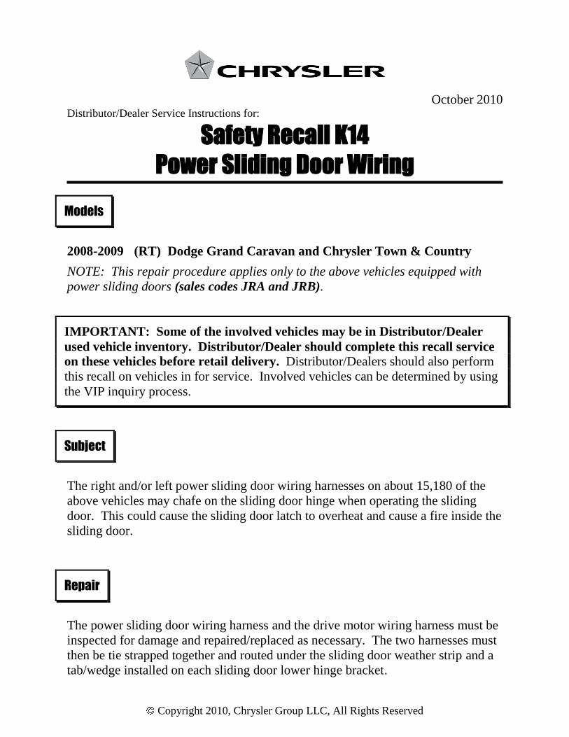
October 2010 Distributor/Dealer Service Instructions for:
Safety Recall K14
Power Sliding Door Wiring
2008-2009 (RT) Dodge Grand Caravan and Chrysler Town & Country
NOTE: This repair procedure applies only to the above vehicles equipped with
power sliding doors (sales codes JRA and JRB).
The right and/or left power sliding door wiring harnesses on about 15,180 of the
above vehicles may chafe on the sliding door hinge when operating the sliding
door. This could cause the sliding door latch to overheat and cause a fire inside the
sliding door.
The power sliding door wiring harness and the drive motor wiring harness must be
inspected for damage and repaired/replaced as necessary. The two harnesses must
then be tie strapped together and routed under the sliding door weather strip and a
tab/wedge installed on each sliding door lower hinge bracket.
Models
IMPORTANT: Some of the involved vehicles may be in Distributor/Dealer
used vehicle inventory. Distributor/Dealer should complete this recall service
on these vehicles before retail delivery. Distributor/Dealers should also perform
this recall on vehicles in for service. Involved vehicles can be determined by using
the VIP inquiry process.
Subject
Repair
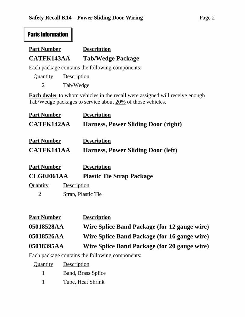
Safety Recall K14 – Power Sliding Door Wiring Page 2
Part Number Description
CATFK143AA Tab/Wedge Package
Each package contains the following components:
Quantity Description
2 Tab/Wedge
Each dealer to whom vehicles in the recall were assigned will receive enough
Tab/Wedge packages to service about 20% of those vehicles.
Part Number Description
CATFK142AA Harness, Power Sliding Door (right)
Part Number Description
CATFK141AA Harness, Power Sliding Door (left)
Part Number Description
CLG0J061AA Plastic Tie Strap Package
Quantity Description
2 Strap, Plastic Tie
Part Number Description
05018528AA Wire Splice Band Package (for 12 gauge wire)
05018526AA Wire Splice Band Package (for 16 gauge wire)
05018395AA Wire Splice Band Package (for 20 gauge wire)
Each package contains the following components:
Quantity Description
1 Band, Brass Splice
1 Tube, Heat Shrink
Parts Information
Safety Recall K14 – Power Sliding Door Wiring Page 3
The following special tool may be required to perform this repair:
10042 Wire Splice Crimp Tool
NOTE: One wire splice crimp tool was mailed to each dealer free of
charge in June, 2007. For warranty issues regarding the wire splice
crimping tool sent in June, contact Wright Tool Company at
1-800-783-9826.
Additional wire splice crimp tools can be purchased, at dealer expense, by
calling Miller Special Tools at 1-800-801-5420 during regular business
hours. Contact Miller Special Tools regarding warranty issues on any
purchased tools.
Special Tools
Safety Recall K14 – Power Sliding Door Wiring Page 4
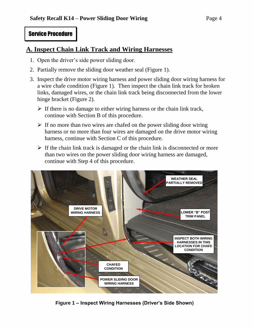
A. Inspect Chain Link Track and Wiring Harnesses
1. Open the driver’s side power sliding door.
2. Partially remove the sliding door weather seal (Figure 1).
3. Inspect the drive motor wiring harness and power sliding door wiring harness for
a wire chafe condition (Figure 1). Then inspect the chain link track for broken
links, damaged wires, or the chain link track being disconnected from the lower
hinge bracket (Figure 2).
If there is no damage to either wiring harness or the chain link track,
continue with Section B of this procedure.
If no more than two wires are chafed on the power sliding door wiring
harness or no more than four wires are damaged on the drive motor wiring
harness, continue with Section C of this procedure.
If the chain link track is damaged or the chain link is disconnected or more
than two wires on the power sliding door wiring harness are damaged,
continue with Step 4 of this procedure.
Service Procedure
Figure 1 – Inspect Wiring Harnesses (Driver’s Side Shown)
WEATHER SEAL
PARTIALLY REMOVED
LOWER “B” POST
TRIM PANEL
CHAFED
CONDITION
DRIVE MOTOR
WIRING HARNESS
INSPECT BOTH WIRING HARNESSES IN THIS
LOCATION FOR CHAFE CONDITION
POWER SLIDING DOOR
WIRING HARNESS
Safety Recall K14 – Power Sliding Door Wiring Page 5
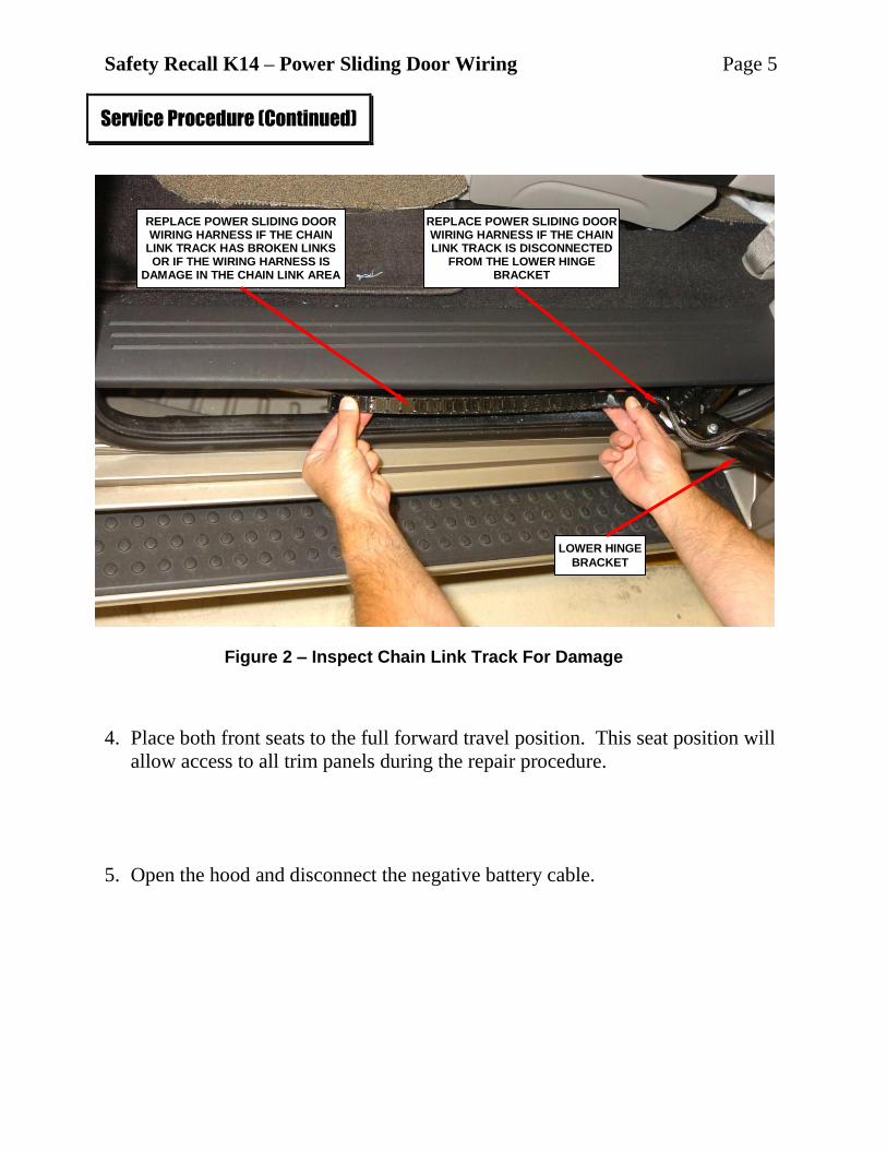
4. Place both front seats to the full forward travel position. This seat position will
allow access to all trim panels during the repair procedure.
5. Open the hood and disconnect the negative battery cable.
Service Procedure (Continued)
Figure 2 – Inspect Chain Link Track For Damage
LOWER HINGE
BRACKET
REPLACE POWER SLIDING DOOR WIRING HARNESS IF THE CHAIN
LINK TRACK HAS BROKEN LINKS OR IF THE WIRING HARNESS IS
DAMAGE IN THE CHAIN LINK AREA
REPLACE POWER SLIDING DOOR WIRING HARNESS IF THE CHAIN LINK TRACK IS DISCONNECTED
FROM THE LOWER HINGE BRACKET
Safety Recall K14 – Power Sliding Door Wiring Page 6
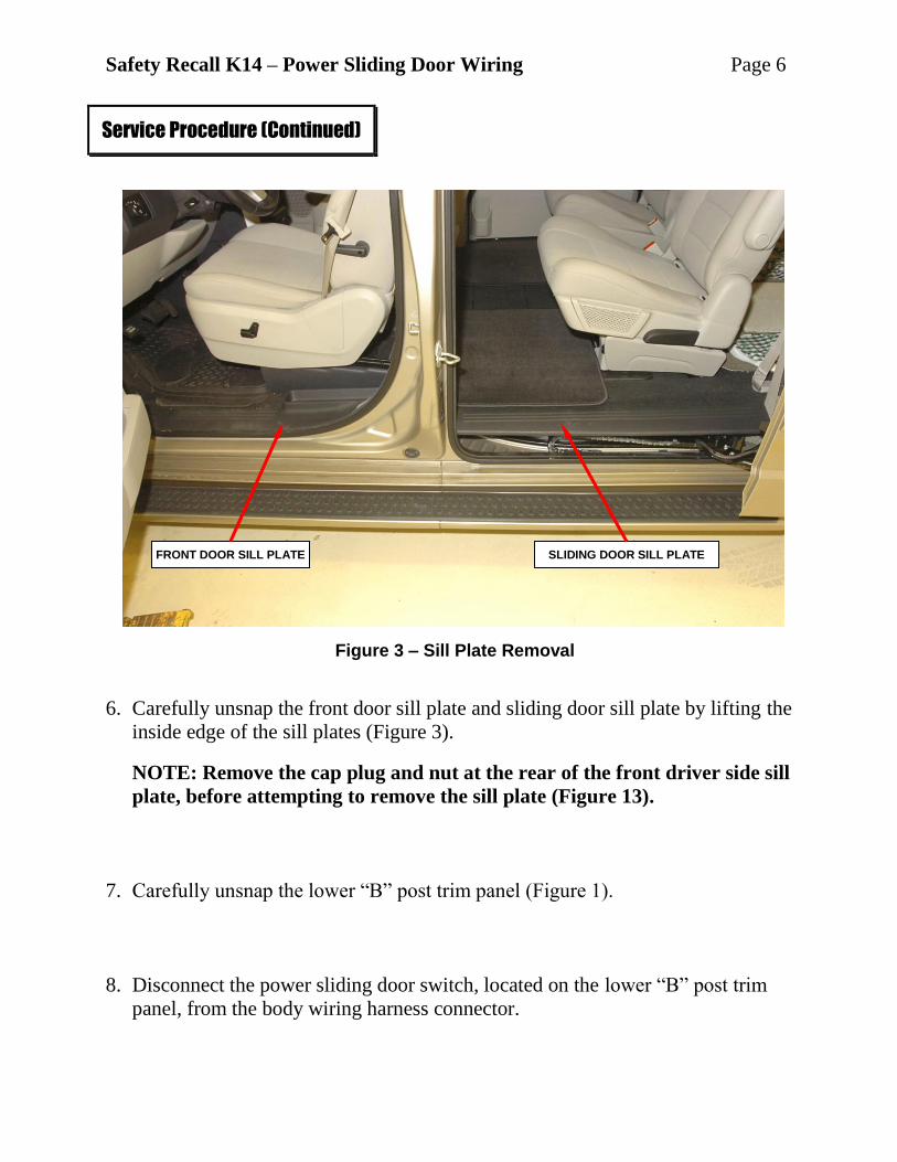
6. Carefully unsnap the front door sill plate and sliding door sill plate by lifting the
inside edge of the sill plates (Figure 3).
NOTE: Remove the cap plug and nut at the rear of the front driver side sill
plate, before attempting to remove the sill plate (Figure 13).
7. Carefully unsnap the lower “B” post trim panel (Figure 1).
8. Disconnect the power sliding door switch, located on the lower “B” post trim
panel, from the body wiring harness connector.
Service Procedure (Continued)
Figure 3 – Sill Plate Removal
FRONT DOOR SILL PLATE SLIDING DOOR SILL PLATE
Safety Recall K14 – Power Sliding Door Wiring Page 7
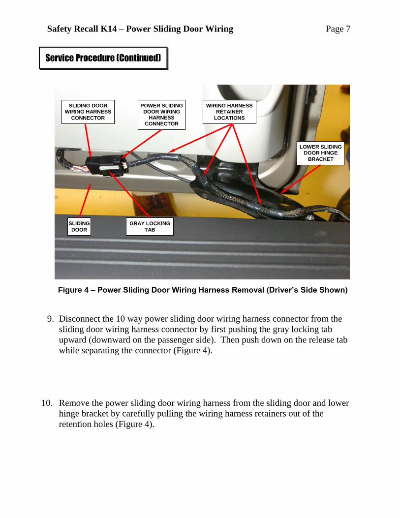
9. Disconnect the 10 way power sliding door wiring harness connector from the
sliding door wiring harness connector by first pushing the gray locking tab
upward (downward on the passenger side). Then push down on the release tab
while separating the connector (Figure 4).
10. Remove the power sliding door wiring harness from the sliding door and lower
hinge bracket by carefully pulling the wiring harness retainers out of the
retention holes (Figure 4).
Service Procedure (Continued)
Figure 4 – Power Sliding Door Wiring Harness Removal (Driver’s Side Shown)
SLIDING
DOOR
SLIDING DOOR WIRING HARNESS
CONNECTOR
GRAY LOCKING
TAB
LOWER SLIDING DOOR HINGE
BRACKET
WIRING HARNESS RETAINER
LOCATIONS
POWER SLIDING DOOR WIRING
HARNESS CONNECTOR
Safety Recall K14 – Power Sliding Door Wiring Page 8
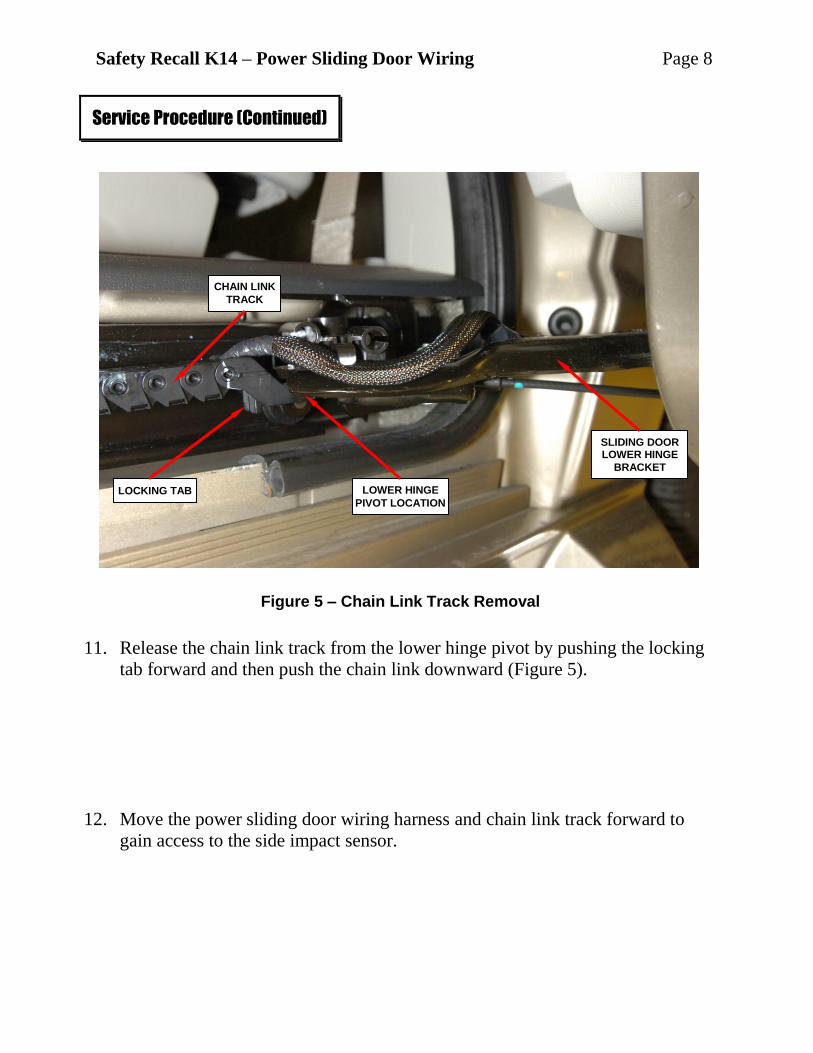
11. Release the chain link track from the lower hinge pivot by pushing the locking
tab forward and then push the chain link downward (Figure 5).
12. Move the power sliding door wiring harness and chain link track forward to
gain access to the side impact sensor.
Service Procedure (Continued)
Figure 5 – Chain Link Track Removal
CHAIN LINK
TRACK
LOCKING TAB LOWER HINGE
PIVOT LOCATION
SLIDING DOOR LOWER HINGE
BRACKET
Safety Recall K14 – Power Sliding Door Wiring Page 9
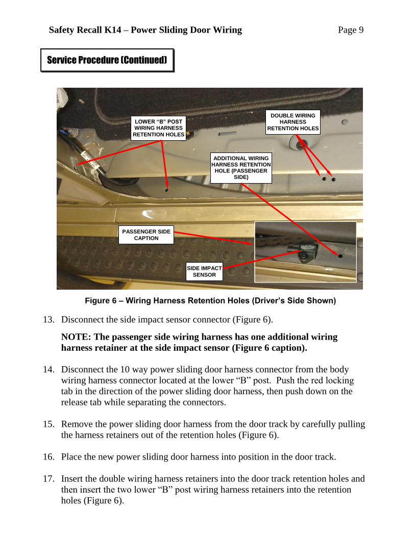
13. Disconnect the side impact sensor connector (Figure 6).
NOTE: The passenger side wiring harness has one additional wiring
harness retainer at the side impact sensor (Figure 6 caption).
14. Disconnect the 10 way power sliding door harness connector from the body
wiring harness connector located at the lower “B” post. Push the red locking
tab in the direction of the power sliding door harness, then push down on the
release tab while separating the connectors.
15. Remove the power sliding door harness from the door track by carefully pulling
the harness retainers out of the retention holes (Figure 6).
16. Place the new power sliding door harness into position in the door track.
17. Insert the double wiring harness retainers into the door track retention holes and
then insert the two lower “B” post wiring harness retainers into the retention
holes (Figure 6).
Service Procedure (Continued)
Figure 6 – Wiring Harness Retention Holes (Driver’s Side Shown)
LOWER “B” POST WIRING HARNESS
RETENTION HOLES
DOUBLE WIRING HARNESS
RETENTION HOLES
PASSENGER SIDE
CAPTION
SIDE IMPACT
SENSOR
ADDITIONAL WIRING HARNESS RETENTION
HOLE (PASSENGER SIDE)
Safety Recall K14 – Power Sliding Door Wiring Page 10
18. Connect the 10 way power sliding door wiring harness connector to the body
wiring harness connector located at the lower “B” pillar and slide the red
locking tab in the direction of the body wiring harness.
19. Connect the side impact sensor connector (Figure 6).
NOTE: The passenger side wiring harness at the side impact sensor has
one additional wiring harness retainer (Figure 6 caption).
20. Move the chain link track and wiring harness rearward.
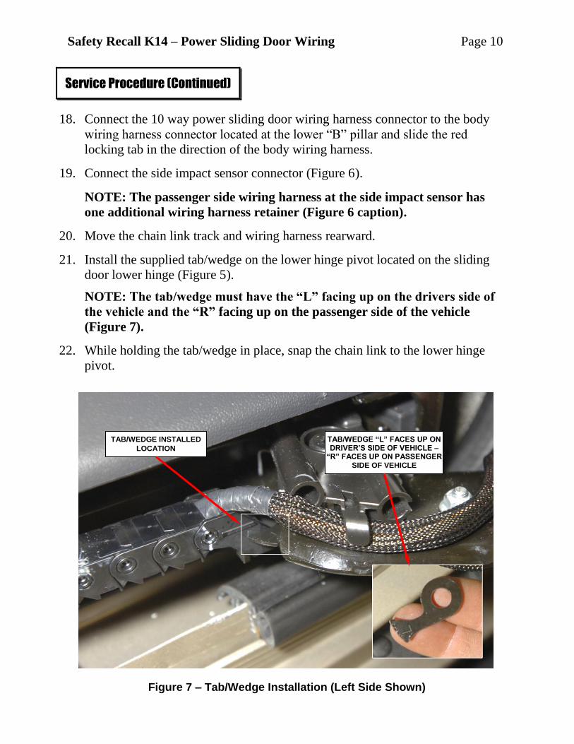
21. Install the supplied tab/wedge on the lower hinge pivot located on the sliding
door lower hinge (Figure 5).
NOTE: The tab/wedge must have the “L” facing up on the drivers side of
the vehicle and the “R” facing up on the passenger side of the vehicle
(Figure 7).
22. While holding the tab/wedge in place, snap the chain link to the lower hinge
pivot.
Service Procedure (Continued)
Figure 7 – Tab/Wedge Installation (Left Side Shown)
TAB/WEDGE INSTALLED
LOCATION
TAB/WEDGE “L” FACES UP ON DRIVER’S SIDE OF VEHICLE –
“R” FACES UP ON PASSENGER SIDE OF VEHICLE
Safety Recall K14 – Power Sliding Door Wiring Page 11
23. Lock the chain link in place by pushing the locking tab rearward (Figure 5).
24. Insert the power sliding door wiring harness retainers into the lower hinge and
sliding door retention holes (Figure 4).
25. Connect the 10 way power sliding door wiring harness connector to the sliding
door wiring harness connector and slide the gray locking tab downward
(upward on the passenger side of the vehicle) (Figure 4).
26. Connect the power sliding door switch, located on the lower “B” post trim
panel, to the body wiring harness connector.
27. Carefully snap the lower “B” post trim panel in place (Figure 1).
28. Carefully snap the front door sill plate and sliding door sill plate in place
(Figure 3).
NOTE: Install the nut and cap plug at the rear of the front driver side sill plate.
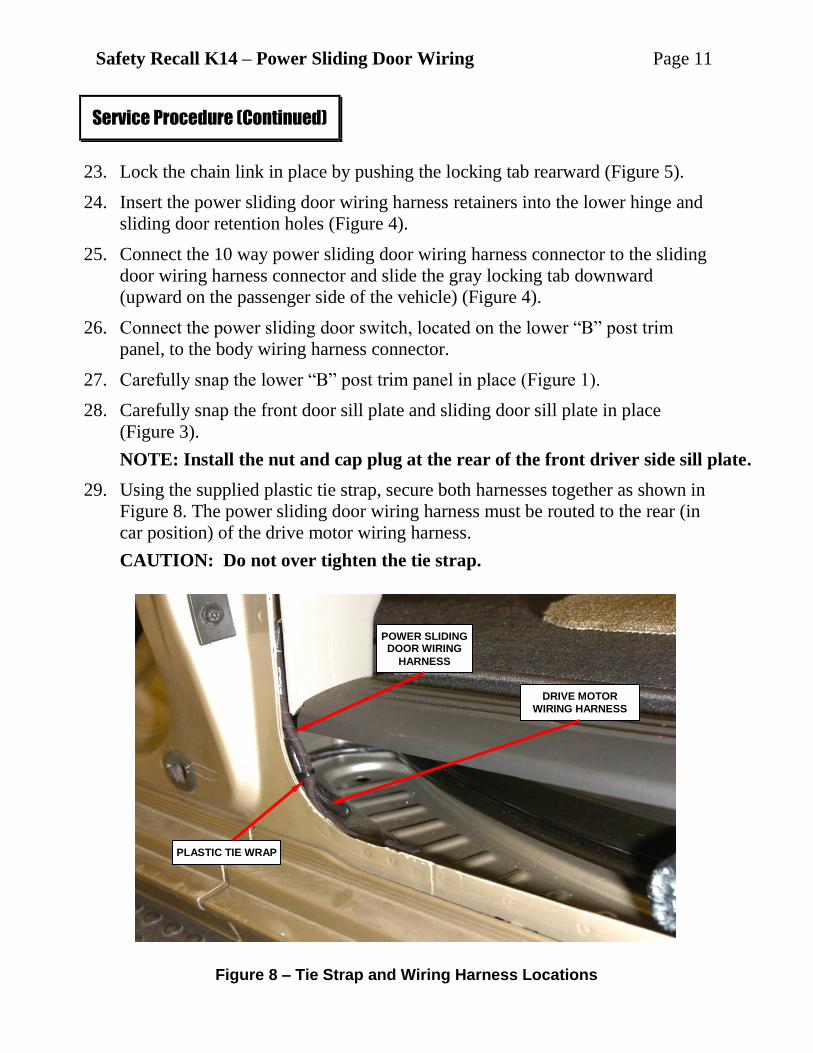
29. Using the supplied plastic tie strap, secure both harnesses together as shown in
Figure 8. The power sliding door wiring harness must be routed to the rear (in
car position) of the drive motor wiring harness.
CAUTION: Do not over tighten the tie strap.
Service Procedure (Continued)
Figure 8 – Tie Strap and Wiring Harness Locations
DRIVE MOTOR
WIRING HARNESS
PLASTIC TIE WRAP
POWER SLIDING DOOR WIRING
HARNESS
Safety Recall K14 – Power Sliding Door Wiring Page 12
30. Cut off the tail of the tie strap and rotate the tie strap so that the tie strap lock is
tucked under the wiring harnesses.
31. Install the partially removed sliding door weather seal. Be sure to tuck the
wiring harness behind the weather seal inner retaining lip.
32. Move the sliding door manually and verify that the lower hinge does not contact
the weather seal and/or any portion of the wiring harnesses.
33. Repeat Section A on the passenger (right) side sliding door.
34. Connect negative battery cable and close hood.
Service Procedure (Continued)
Safety Recall K14 – Power Sliding Door Wiring Page 13
B. Install Tie Wrap and Tab/Wedge
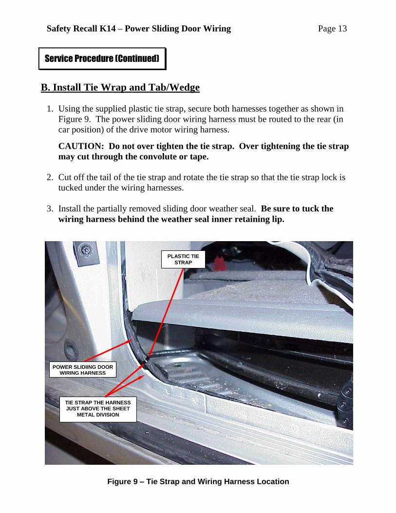
1. Using the supplied plastic tie strap, secure both harnesses together as shown in
Figure 9. The power sliding door wiring harness must be routed to the rear (in
car position) of the drive motor wiring harness.
CAUTION: Do not over tighten the tie strap. Over tightening the tie strap
may cut through the convolute or tape.
2. Cut off the tail of the tie strap and rotate the tie strap so that the tie strap lock is
tucked under the wiring harnesses.
3. Install the partially removed sliding door weather seal. Be sure to tuck the
wiring harness behind the weather seal inner retaining lip.
Service Procedure (Continued)
Figure 9 – Tie Strap and Wiring Harness Location
TIE STRAP THE HARNESS JUST ABOVE THE SHEET
METAL DIVISION
PLASTIC TIE
STRAP
POWER SLIDIING DOOR WIRING HARNESS
Safety Recall K14 – Power Sliding Door Wiring Page 14
4. Move the sliding door manually and verify that the lower hinge does not contact
the weather seal and/or any portion of the wiring harnesses.
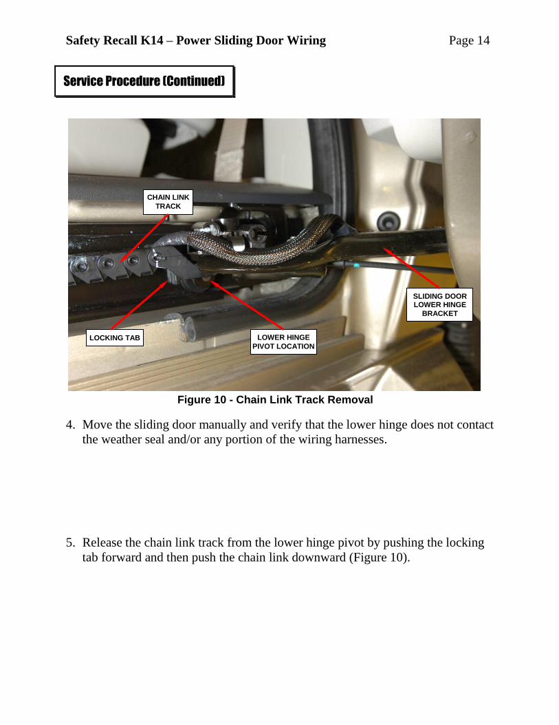
5. Release the chain link track from the lower hinge pivot by pushing the locking
tab forward and then push the chain link downward (Figure 10).
Service Procedure (Continued)
Figure 10 - Chain Link Track Removal
CHAIN LINK
TRACK
LOCKING TAB LOWER HINGE
PIVOT LOCATION
SLIDING DOOR LOWER HINGE
BRACKET
Safety Recall K14 – Power Sliding Door Wiring Page 15
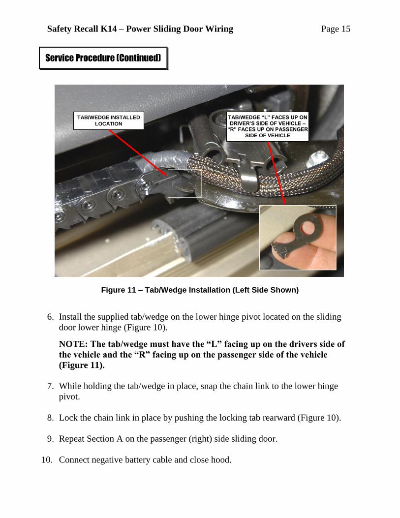
6. Install the supplied tab/wedge on the lower hinge pivot located on the sliding
door lower hinge (Figure 10).
NOTE: The tab/wedge must have the “L” facing up on the drivers side of
the vehicle and the “R” facing up on the passenger side of the vehicle
(Figure 11).
7. While holding the tab/wedge in place, snap the chain link to the lower hinge
pivot.
8. Lock the chain link in place by pushing the locking tab rearward (Figure 10).
9. Repeat Section A on the passenger (right) side sliding door.
10. Connect negative battery cable and close hood.
Service Procedure (Continued)
Figure 11 – Tab/Wedge Installation (Left Side Shown)
TAB/WEDGE INSTALLED
LOCATION
TAB/WEDGE “L” FACES UP ON DRIVER’S SIDE OF VEHICLE –
“R” FACES UP ON PASSENGER SIDE OF VEHICLE
Safety Recall K14 – Power Sliding Door Wiring Page 16
C. Wiring Harness Repair
1. Place both front seats to the full forward travel position. This seat position will
allow access to all trim panels during the repair procedure.
2. Open the hood and disconnect the negative battery cable.
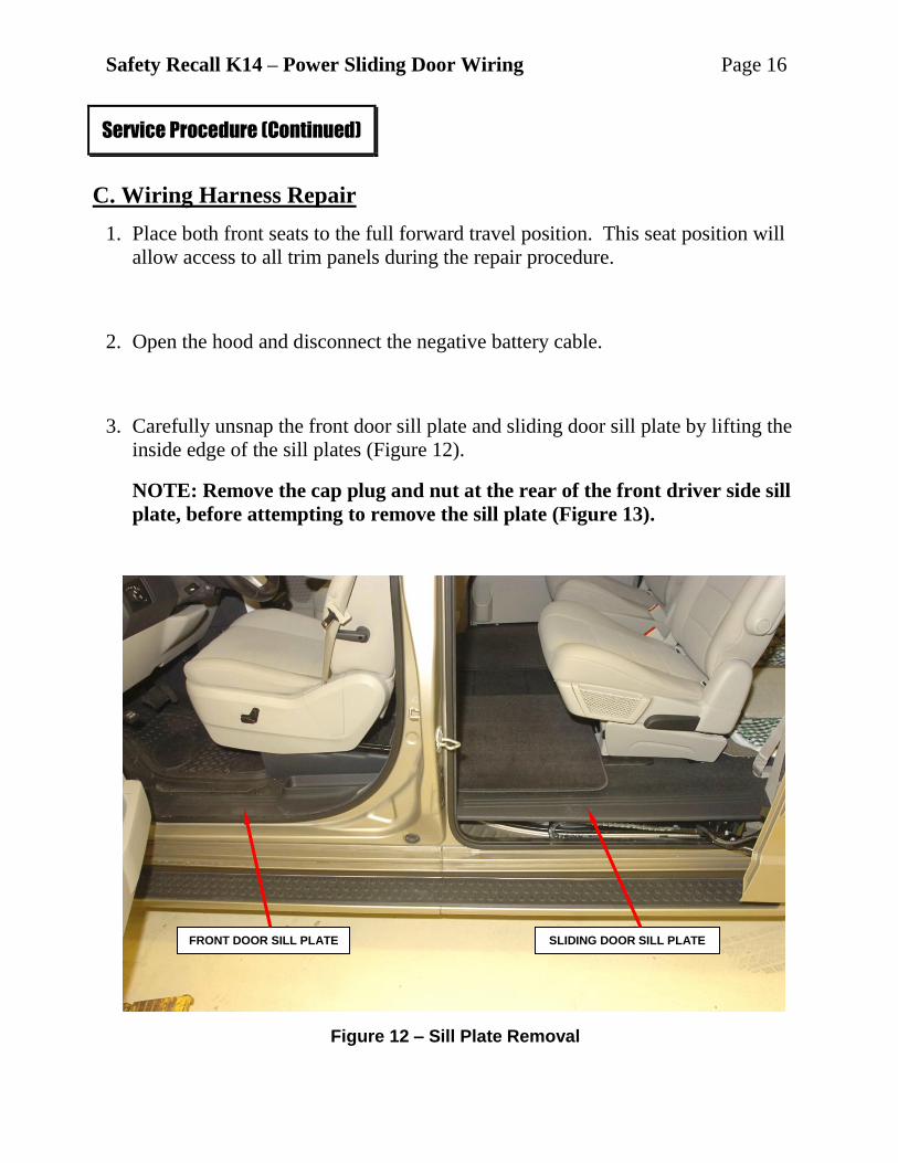
3. Carefully unsnap the front door sill plate and sliding door sill plate by lifting the
inside edge of the sill plates (Figure 12).
NOTE: Remove the cap plug and nut at the rear of the front driver side sill
plate, before attempting to remove the sill plate (Figure 13).
Service Procedure (Continued)
Figure 12 – Sill Plate Removal
FRONT DOOR SILL PLATE SLIDING DOOR SILL PLATE
Safety Recall K14 – Power Sliding Door Wiring Page 17
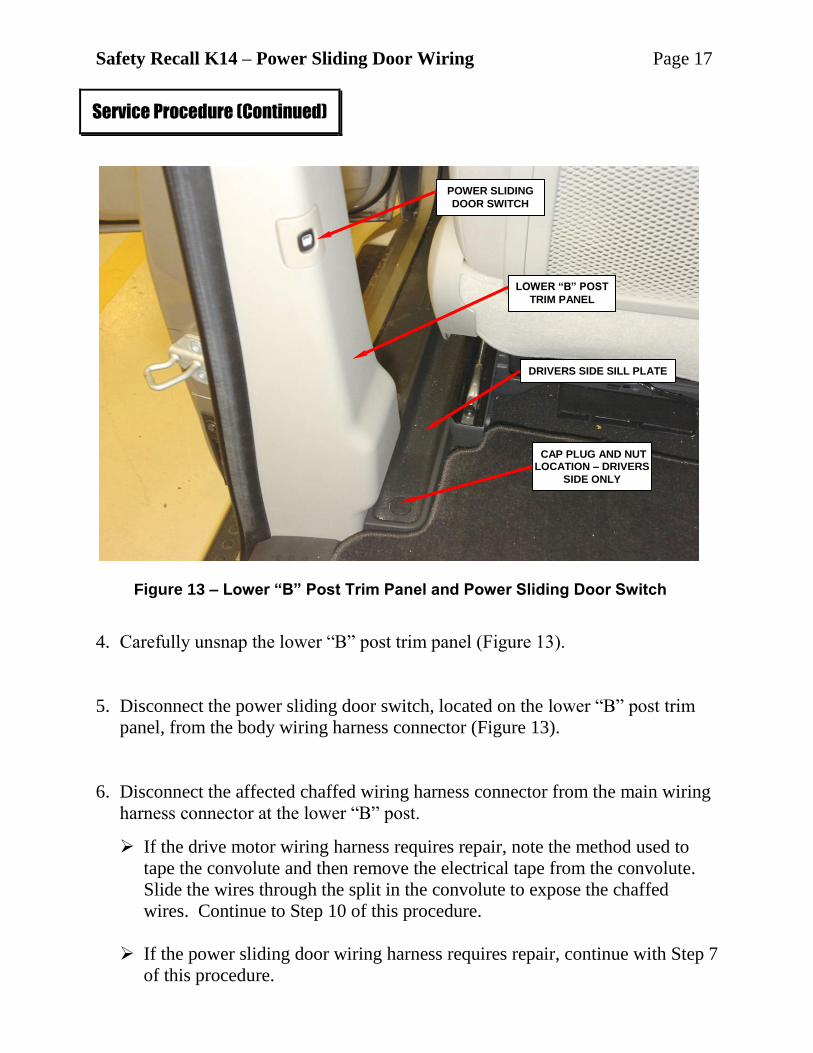
4. Carefully unsnap the lower “B” post trim panel (Figure 13).
5. Disconnect the power sliding door switch, located on the lower “B” post trim
panel, from the body wiring harness connector (Figure 13).
6. Disconnect the affected chaffed wiring harness connector from the main wiring
harness connector at the lower “B” post.
If the drive motor wiring harness requires repair, note the method used to
tape the convolute and then remove the electrical tape from the convolute.
Slide the wires through the split in the convolute to expose the chaffed
wires. Continue to Step 10 of this procedure.
If the power sliding door wiring harness requires repair, continue with Step 7
of this procedure.
Service Procedure (Continued)
Figure 13 – Lower “B” Post Trim Panel and Power Sliding Door Switch
POWER SLIDING
DOOR SWITCH
LOWER “B” POST
TRIM PANEL
CAP PLUG AND NUT LOCATION – DRIVERS
SIDE ONLY
DRIVERS SIDE SILL PLATE
Safety Recall K14 – Power Sliding Door Wiring Page 18
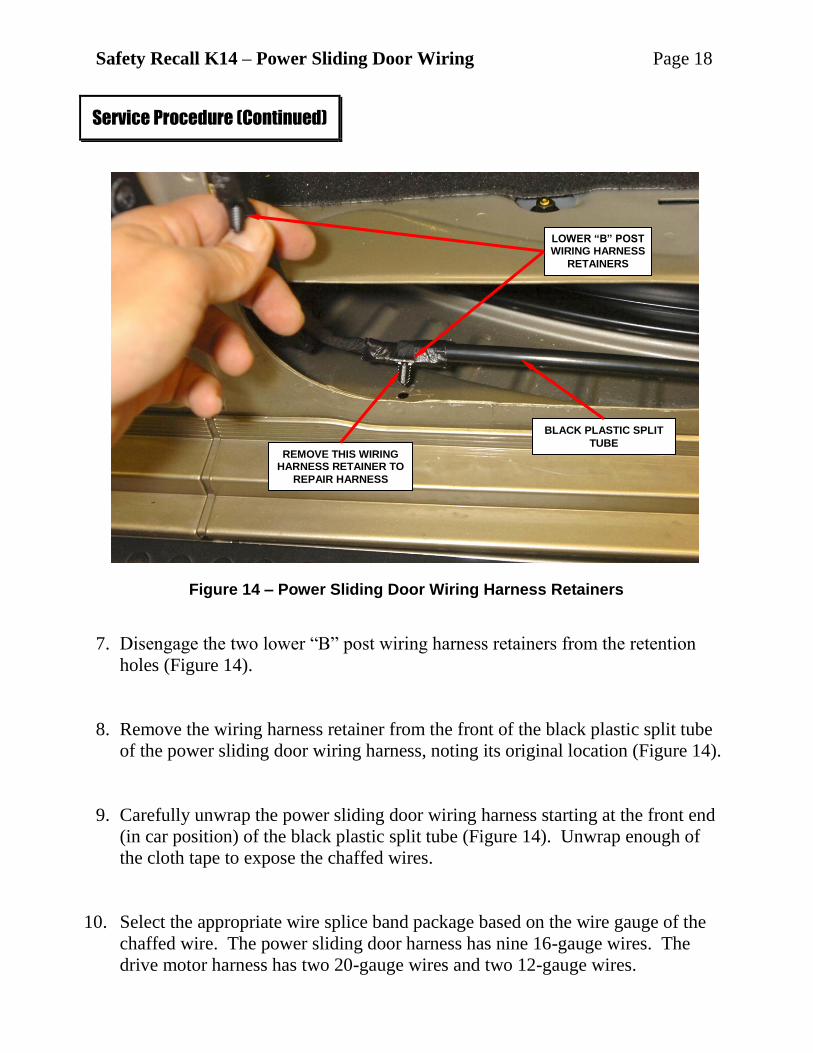
7. Disengage the two lower “B” post wiring harness retainers from the retention
holes (Figure 14).
8. Remove the wiring harness retainer from the front of the black plastic split tube
of the power sliding door wiring harness, noting its original location (Figure 14).
9. Carefully unwrap the power sliding door wiring harness starting at the front end
(in car position) of the black plastic split tube (Figure 14). Unwrap enough of
the cloth tape to expose the chaffed wires.
10. Select the appropriate wire splice band package based on the wire gauge of the
chaffed wire. The power sliding door harness has nine 16-gauge wires. The
drive motor harness has two 20-gauge wires and two 12-gauge wires.
Service Procedure (Continued)
Figure 14 – Power Sliding Door Wiring Harness Retainers
LOWER “B” POST WIRING HARNESS
RETAINERS
BLACK PLASTIC SPLIT
TUBE REMOVE THIS WIRING
HARNESS RETAINER TO
REPAIR HARNESS
Safety Recall K14 – Power Sliding Door Wiring Page 19
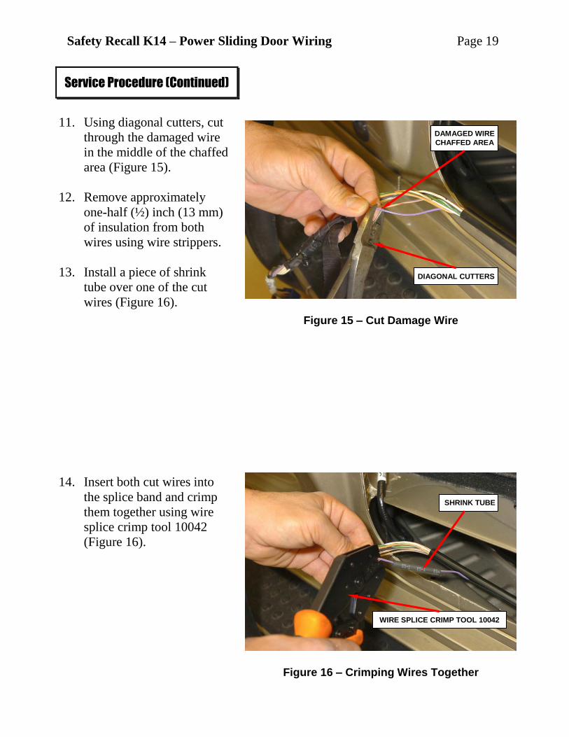
11. Using diagonal cutters, cut
through the damaged wire
in the middle of the chaffed
area (Figure 15).
12. Remove approximately
one-half (½) inch (13 mm)
of insulation from both
wires using wire strippers.
13. Install a piece of shrink
tube over one of the cut
wires (Figure 16).
14. Insert both cut wires into
the splice band and crimp
them together using wire
splice crimp tool 10042
(Figure 16).
Service Procedure (Continued)
Figure 15 – Cut Damage Wire
DIAGONAL CUTTERS
DAMAGED WIRE
CHAFFED AREA
Figure 16 – Crimping Wires Together
SHRINK TUBE
WIRE SPLICE CRIMP TOOL 10042
Safety Recall K14 – Power Sliding Door Wiring Page 20
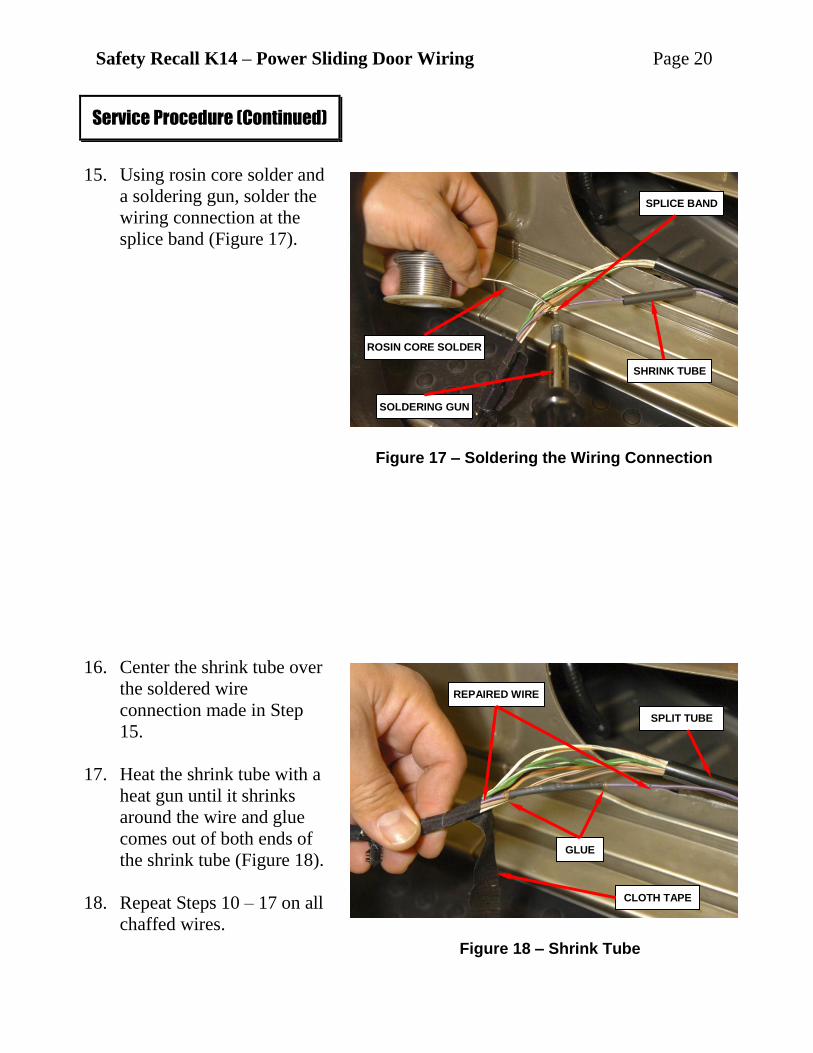
15. Using rosin core solder and
a soldering gun, solder the
wiring connection at the
splice band (Figure 17).
16. Center the shrink tube over
the soldered wire
connection made in Step
15.
17. Heat the shrink tube with a
heat gun until it shrinks
around the wire and glue
comes out of both ends of
the shrink tube (Figure 18).
18. Repeat Steps 10 – 17 on all
chaffed wires.
Service Procedure (Continued)
Figure 17 – Soldering the Wiring Connection
SOLDERING GUN
ROSIN CORE SOLDER
SHRINK TUBE
SPLICE BAND
Figure 18 – Shrink Tube
CLOTH TAPE
GLUE
REPAIRED WIRE
SPLIT TUBE
Safety Recall K14 – Power Sliding Door Wiring Page 21
19. When all chaffed wires have been repaired, position the wires in the
convolute/split tube (Figure 18).
If the drive motor wiring harness was repaired, tape the drive motor wiring
harness with electrical tape as noted in Step 6. Continue with Step 22 of this
procedure.
If the power sliding door wiring harness was repaired, tape the wiring
harness using the cloth tape that was previously unwrapped in Step 9
(Figure 18). Continue with Step 20 of this procedure.
20. Position the wiring harness retainer at the end of the split tube and tape the
wiring harness retainer in place with electrical tape (Figure 14).
21. Insert the two lower “B” post wiring harness retainers into the retention holes
(Figure 14).
22. Connect the drive motor wiring harness connector or the power sliding door
wiring harness connector to the body wiring harness connector at the base of the
“B” post.
23. Connect the power sliding door switch, located on the lower “B” post trim
panel, to the body wiring harness connector (Figure 13).
24. Carefully snap the lower “B” post trim panel in place (Figure 13).
25. Carefully snap the front door sill plate and sliding door sill plate in place
(Figure 12).
NOTE: Install the nut and cap plug at the rear of the front driver side sill
plate (Figure 13).
26. Continue with Section B of this repair procedure.
Service Procedure (Continued)
Safety Recall K14 – Power Sliding Door Wiring Page 22
Claims for vehicles that have been serviced must be submitted on the
DealerCONNECT Claim Entry Screen located on the Service tab. Claims
submitted will be used by Chrysler to record recall service completions and
provide dealer payments.
Use the following labor operation numbers and time allowances:
Labor Operation Time
Number Allowance
Inspect right and left sliding door wiring
harnesses and chain link track, tie
strap/route harnesses under weather strip
and install tab/wedge. 08-K1-41-82 0.2 hours
Related Operations
Replace right sliding door wiring harness. 08-K1-41-50 0.4 hours
Replace left sliding door wiring harness. 08-K1-41-51 0.5 hours
Repair right sliding door wiring harness
one or two wires. 08-K1-41-52 0.7 hours
Repair left sliding door wiring harness
one or two wires. 08-K1-41-53 0.7 hours
Repair right drive motor wiring harness
one to four wires. 08-K1-41-54 0.7 hours
Repair left drive motor wiring harness
one to four wires. 08-K1-41-55 0.7 hours
Add the cost of the recall parts package plus applicable dealer allowance to your
claim.
NOTE: See the Warranty Administration Manual, Recall Claim Processing
Section, for complete recall claim processing instructions.
All involved vehicle owners should be notified of the service requirement by their
Distributor/Dealers. Owners are requested to schedule appointments for this service.
Completion Reporting and Reimbursement
Owner Notification and Service Scheduling
Safety Recall K14 – Power Sliding Door Wiring Page 23
All involved vehicles have been entered into the Global Recall System (GRS) and
Vehicle Information Plus (VIP) for distributor/dealer inquiry as needed. GRS provides involved Distributor/Dealers with an updated VIN list of their
incomplete vehicles. Completed vehicles are removed from GRS within several days
of repair claim submission.
Distributor/Dealers should perform this repair on all unsold vehicles before
retail delivery. Distributor/Dealers should also use the VIN list to follow up with
all owners to schedule appointments for this repair.
If you have any questions or need assistance in completing this action, please
contact your International Service and Parts Manager.
Global Service & Parts – International
Chrysler Group LLC
Vehicle Lists, Global Recall System, VIP and Distributor/Dealer Follow Up
Additional Information
______________________________________________________________________________________
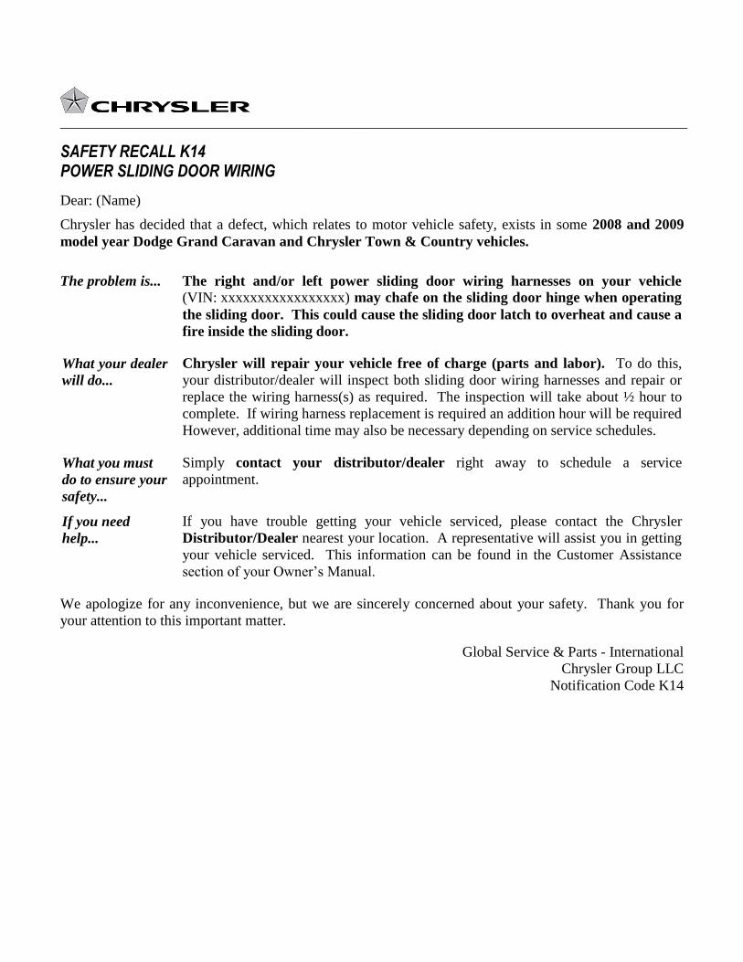
SAFETY RECALL K14 POWER SLIDING DOOR WIRING
Dear: (Name)
Chrysler has decided that a defect, which relates to motor vehicle safety, exists in some 2008 and 2009
model year Dodge Grand Caravan and Chrysler Town & Country vehicles.
The problem is... The right and/or left power sliding door wiring harnesses on your vehicle (VIN: xxxxxxxxxxxxxxxxx) may chafe on the sliding door hinge when operating
the sliding door. This could cause the sliding door latch to overheat and cause a
fire inside the sliding door.
What your dealer
will do...
Chrysler will repair your vehicle free of charge (parts and labor). To do this,
your distributor/dealer will inspect both sliding door wiring harnesses and repair or
replace the wiring harness(s) as required. The inspection will take about ½ hour to
complete. If wiring harness replacement is required an addition hour will be required
However, additional time may also be necessary depending on service schedules.
What you must
do to ensure your
safety...
Simply contact your distributor/dealer right away to schedule a service
appointment.
If you need
help...
If you have trouble getting your vehicle serviced, please contact the Chrysler
Distributor/Dealer nearest your location. A representative will assist you in getting
your vehicle serviced. This information can be found in the Customer Assistance
section of your Owner’s Manual.
We apologize for any inconvenience, but we are sincerely concerned about your safety. Thank you for
your attention to this important matter.
Global Service & Parts - International
Chrysler Group LLC
Notification Code K14