Embed Size (px)
Citation preview
SALISBURY REAR AXLES
First published in MOTOR TRADER
May 28, 1958
MtJflu!tJCfunrs: Solisburl' TrtutSllliuion Co., Lld .• Birch Rood, W;"on,
Birminghum, 6.
-N1TIi very few cl>tcpl ions., in Ih" IllCl<km vehicle the crankshaft '!Us rUDS paraDe! to the leIlj:th
of the fnun", Thus it is netC'S~,. to turn the drive through 90 dei, while at rho: same time it is desirable \0 pcovidc ... mh>etioo ratio between tho: outJ'l!-t shaft of the gcarbol< and Ihe shaClS driving the tear wheels. To IIlttt these dual requirements bevel gearing, i.e., • drive gclU" (crown wheel) and pinion, ate used in the maioritY of cases.
While str.1fght-toothnl bevel ge.ars would provide the neceuary rcductlon and change of plane:- of rotaLion. thC"5C an: noisy in opo:ntioo, and it Wit soon found (bar spir.LI bevel eean nm more quu,tly and were more robu51 because they provided greater area of tooth contact for iiven dimalsil;nu. A lunhu dcvclOpn1ent has ~ hypoid ~ri~lg, i,n which the centre line 01 the plDlOO IS offllCt below that of !.he: drive gear. This further in=~ the area of tooth con tact and thus aivcs cv.::n more robuu units.
the same lime it givn quieter running, • allows the use or a lower propc U er ~
duIll mouming, permitting a Icwer floor line 10 be given to the body. Due to the combined rubbing and meshinf action of hypoid ge:m a s~ial type 0 lubricant is required which must be used, other~ ""oc Walr IlI1d failure wiU occur I'lIIpidly.
:':cept when a vehicle is tl'lllvelling in 10 1(l'lIIight tioe the rear wheels will alwaya be tuming at ditf,,",nt spttds. Thi5 is ~use on I C'U!VC tbe vclUclc followl me diametet of a citcle whose radius is coincidmtal wilb the u4 or the lear whttl;s, so that the inoer wheel is tnvelling in a smaller circle than the t".lIer onc. Unless a Vl:hiclc has a very narrow rear rnck it is necessary to allow for Ielative rotation between the lear
GU(RAI. DATA
, I ~ .~ .~ .... W"~ ~IJ ~.- "'_ Mo I .... ':,t' ... , • , .. .. , n .. ,..- '.-· ,., .~ .. tl._ .-,., " -1- " "'" -
· , .. .u , ,,- ,-• .
'" " I , ,,- -
'H~ .M , 1lI,1I 2 ',oM
wheels and ttm i$ the functiDn of the ditferential. Torque from the drive &caT is applied to two or more bevel gcal1, frtt to rouue on a daft, which mesh Wilh bevel JC:It'S on the .ule &buu (half tbafts). While the torque is normally divided equally between the two .ule shafts, the rotation of the one shut with relation to the other is not opposed.
With the above rype of dilfermtial it is apparent that if one wbccl is free to rum the other will remain stationuy. Thus if one wbeel Sllrts to skid 011, say, an icy road, the vehicle will nOI be driven fot~
ward. A. modified type or difl'eremial i$ possible which aUows gradual "creep" between the two axle shafts but wtuch will tr.lnsmit torque to both 5ba(1$ even if one is fr« to turn.
Still the most common. fono of reara.de. luspcmion, although , ubjcct to much valiation in detail, is me HOIchki" drive. In this des.ign the wheels Ire mounted on a ria:id rear ule which is IIm:hored 10
semi-elliptic springs raained on the chassis (rame. Driving and rear axle bn kjfL(l torques arc uansferred to the chassis frame via the springs, which, thucfore sc:rYe a double purpose. Since with this arnnlcmcnt the nle will not only till, but iu distaoce from the gearbox will vary, the propeller shaft ia of the open ryr with universal joints III either md an It !.liding coupling, now often embodied in the gearbox.
Onc of the diudvantages of this s)'$tem is that the rear uk is pan. of the unspnmg weight. For special applications, such IS sports c:ars, it may be dc:sircd to raluoe unspnma weight to a minimum, dest: the increased cosu of a more comp' ted arrangtmenl. To redul;( unsprung weight, the IllUi drive and d ifferential arc made as a $Cpar.lle unit supported on the <:hauis frame while the whcels, either indcpcndcntlf sprung or on a s.epante lightweight I'lgid rear axle, called a de Dion uk, arc driven by univenally jointed drive malts. Saliabury axles modds 3HU and 4HU arc compaCt final driVe aod rea: nle units suitab1c for thrs purpose.
Apan from the above applications it will be seeo that the rear axle supportS a proportion of rhe wc i~ht of the vehicle as well as conV1:ying dnve to the wheels. Sina: the axle casing and drive ,hafts are both anilable for suPportinl the weight of me vehicle a number or different hub aaangemcnu are possible. Thes.e vary from mounting the whecb direct on axle shalt$ supported in lournal bcarinas and retained at their inner ends (non-Boating) to mountint: the wheels on the axle casing on double-thrust bearing and driving them with tlanged drive &hafu (fully floating).
Rear nles made by Salisbury Trans_ minions. Ltd .• are widely employed for eus, all tY~ s of com.m~al veruc[et., industn-I vehieles, and 50 O!". A feJotu!t'. of the de"jlns is that the drive lear, pInion
"'CIAL TOOU
c;.., Ltd., , MI141uoL
and ditfercntiaJ are mounted in a rigid central Clrrier into which the stcel axle tubes arc pressed and plul_welded.. This permits $Iandardization of the main CODl
poIlenU while the design is easily adaptable to a wide range of wheel tfadi;S and hub arrangements. The hubs are of Ihe 5emi-ftoadng pauern in the majority of cases, in whicb the wheel is lllpered and keyed 10 the axle shaft, which runs i .. a ~glc thrust tapcr roller bearing inside the axle lube. Sideways location is pro
vided by the opposed thrust bearinlS, the axle shafl$ both o:mla<:Una: a central $PlUf to tran$l'er rhruSL
In leneral the u!e load rating governs the rype of axle fining to a particular vehicle, and there arc, of o)UfS.e, many different final drive ratios available lor each type of axle. As original equipment, the lypc of axle is roOlicn aft ~r careful consideration of eogioe lorque, tyre size, r~ aIle load, and so on, thucfore an ax le should only be replaced with the same type. Similarly, nole should be wen tha! any non-standard fearure of a vehicle , such as a different or specially-tWled (n,ine, l.rltr lyre s.ize or increased loadnung may affect the Iype of axle required. The lI.'(le gear ratio is $Iamped on a talr attached to an assembly by one of the rear cover SClewS. The "le seria l nwnber, which should .lwaYI be quoted in correspondence, is Stamped 011 the gear carricr housing.
Owing to robust constructio:a and plannw. lubrication, wear on I Sllisbu.rr. axlE is usually gmcral nther IhllI1 Inca , and jf an AXle requires suvicin& after a long period of use il should be borne in mind that replacement axles arc available througb the vehicle manufacturers in mO!t CliIJe5. Premature failure is probably due to misuse, faultY servicing or i ncor ~cc t
lubrK:ation. If it is DCttlISary to ICPI" a Salisbury asle in tm~ .. ncy certain opentinos an be performed without t h ~ .use of special tools. For JlO[mal servlO.Og, how~vc r, special tools ue neeenal')' and these Ire listC'd here. Thread. and hexaIons Ire in the main U.N.F.
CONSTRUCTION The build-up of the .u:Jc tubes and gear
carrier havc already been desaibcd. The pinion is supported and 10CIt1C'd in the
Seryjc;irij; Guide 10 Brit ish Motor Vehic;l~
gear carri.tr by opposed th ruSt t.per rolkr bcuings. Sbinu arc tilled belween the eup of the inner baring and the: shoulder which IO(:ln£s il in the tat carrier co adjust the: depth of meioh of the: pin ion. On tho: 'plined end otlhc:. pinion wft fits the companion f1an;e of dinkNion to 'Uil Hardy Spic;er or uyrub join!), rttained by • washe r and caslellated nUl a,ainst th: (Onc of the outer Ixari"l!' Sinc:c the diu:lDC:C between the be.1UI& (UP' is dclennin«l by their Ioation .pinst )bouldcn in the gear earricr, the pn:1oad of the: beanns, is nu.blishe:d by the distUII:C bclWet:O the- c;:oncs- This i, adjUSted by ::hims betW(m me cone of me outer bearin, and • spacer nstio, on Ihe (00<:
of the inner bc:uing. or bc1:Wttrl the cone:
of the outer bearing and a shoulder on the pinion $haft. A lipped meta l dust seal j ~
prcsscd .gainst a sbouldtr on the c:ompanion tlan,e and a lipped. oil seal is prc:»cd inlo a ro:cus in the sear carrier, an oil slingu fluiog bC1wec:n the companion f1qe and tbe outer tlper roUe: bearin,.
Tbc drive cnr and, ~:~:;~~ \mit also run in taper roller _ ~ the Itar anner. Se:m.i-cin;ulil r rt-c:cun arc machined in 10 locate the (UPS of the arc rctaintd by bolted-oo Shims lte tilled b<:rwem clISe alXi the bearing- ~~~. dimmsion dttermining bcarincs Ind the between the two of the drive sar. on the differential CISoC, to the drive gear is Inac:hed by seI3oCr.:WS lodo:cd by IIbt, and the difFcrenlilll ClII C has IWO subs tam~ 1 webs bridging tbe dill'trnllial snn.
Two bevel-toothed $ido: gun h)ye iatemally splined bubs which rqtiSle r in n:<:nscs ill the aides Ilf the difrCfential ar.:sc:, flat thtuR IIIIshcn bcin, filled between the scars aDd the caw ITIC1hing with thc side ~ r s and twO dor hcall'JdUly u1~ fOUl are filled) pinion males (di ffcrcnti31 pinions) free 10 rOllle on a shal t located in I cross-bon: in the dilferential case and rc taincd by a laper pin. Thf thrust f:lc:cs of the pin;DrI malts an:
Componenu 0( a typocal Salisb"". no, a",*,. Nof" cannrllC'tia<! 0( ule (oninl wllidl al~ can.i<ktoble /fUiOiliry it! dEI/,,, (a, di!fettt>t velI;c1es
Itif~l :
I/troulll a SolislHl'1 a1(/e. Comporc mcIhad a( !ace/ti"t cM: c_ 0( IlIe outer pinion bN, /nf " illl that *.1:. I" wllidl 0 diS!olKC piece Is
~,
spherically formed and spherical thtull wau,en fit belween these fxcs .ad the diflen:ntia.l cue. The axle shafu h:1ve splined ends which cnsq:e in the side gears, find their ends abul on • Ipater surroumlina: the pinion male shaft.
At their outcr mds tbe driwe thafn an: Ihreadcd, tape red and kr)'w (usually) for attaChment o f the wheel hubs. The cone of l taper ['I)lkr bearing is prcs.scd up agaiost l $hou.ldcr 00 tech &:lIe shafl, the cup beinl b:alcd in I rea:u in the ule lube. The outer ncc is m:lined by I sp«ial plate or tbe brake bad:; plilte, which is bolted 10 a Hang<: on the a:de lube along with the hub seal. Shims bctwttn the ftangn and the back plates govcrn the tnQ position of the eups. and thus the ule shut cnd float. Aoothu oil seat, lip in.yards. fits inside the axle tube bnrin,g on the nle shafl.
Drive unitS for use with 1Ddcpcnden[ or de D ion rur 5usPfnsion arc similarly conSlnKled but hlye no nIc IUbes, stub axl<: lJi~ ft s being suppon ed by double ,hnJu l a~r milt!' beuings direct in the sur arner.
MAINTENANCE There arc no TUnnins adjustmcnu, and
main tcnana: is confined. 10 lubrication of tbc final drive and of the hub bearings. Alt~ fin, 500 miles. Drain oil .nd
refill. Drain plua: is on Wld.:nide of gclt carrier housing and combined flUel and lC"Yo:i plug is on rear O(Iver. Draining is p referably CII rlied OUI after -nhic.le has bem run to warm oil thoroughly.
G rnse bub bearings.. Ewry 1.500 miles oc moutbly. Chcc:k
oillcvcl in axle and top up if n«usaIY. GrCllse hub bearings. Evuy 10,000 =ilcs Of ,ill: mootbl..
Drain oil f rom axle and refill. NOIes.. Only oils shown in tbe table
of recommended lubricanu should be used, due to diG $pmal requifcmcnrs of hypoid JC"IfI. Oils of the approved brands should nOI be mixed. If there is Iny doubt 11 to wbic:h lubricant is in the axle, it should be dnino:d , Hushed with the new lubriant and '!\cn n:fillcd. Use of f1ush;na: oil may cause dlngerous d.ilution. Tbe additioo of any proprielary coar.pound$ 10 rcwmmended oils IS not approved $iDee this Rl.Iy C1I use ~eroUl dilution aod ilear fallure..
Note thar the bub bearinK housing iJ $CpanlCd from the axle lubricant by a sui and thus tbe bearing rclio:s on grease alone lor lubrication. 'Ibc grease nipple is located in the a~ lube bOUlin, behind 1he brake b&c:kpllle. Where a vent hole is provided., ,tease l>hould be added umil greue is lorced from the hok. Not only does this indicate thQt the hausin, is full , but also it provides a seal aillUlu the inSCC5s of dirt .. nd wale r.
•
REMOVING and REPLACING AXLE SHAFTS
To remove an axle ,haft, jack up n le on S!:IOOs and iUl lOve road wheel, brake drum and hub. Withdraw hub with Suilable ClttI1lCtOt (ydl ic;le manufac:IWefS supply ennrctor). a..f\cr removing split pin castellated nUl and washer.
Check end aOlI 01 ."le shaft with dial indicator ,uscmbly. Correct tolerance lor end Hoa t is .006-.008in. Remoye brakc backplflte rc"ining boilS , bearing retaining plate (il" fitted) aDd brake b;rckplate, lakin~ tare nol la lose or damage any of the shims. Runov~ n le shaft complete with tlpet" roller bearing (loo! no. S£102).
If the axle shall hu brok~, a length will be left protruding from splinc:d side gear. To rc.mowe tllis, make I loop at eDd 0( pica 01 sliff wire, slide loop down nl~ tube and O.·Cr brokc" ade shaft 10 th.t whcn wirc is pulled, loop will til!,hleD oycr Shaft 3nd withdraw 1.1 from ~Ide ,elr. EQmine axle stufl 01
.. "'(OVT[R END)
DRIVE:
'0< (INNER CND)
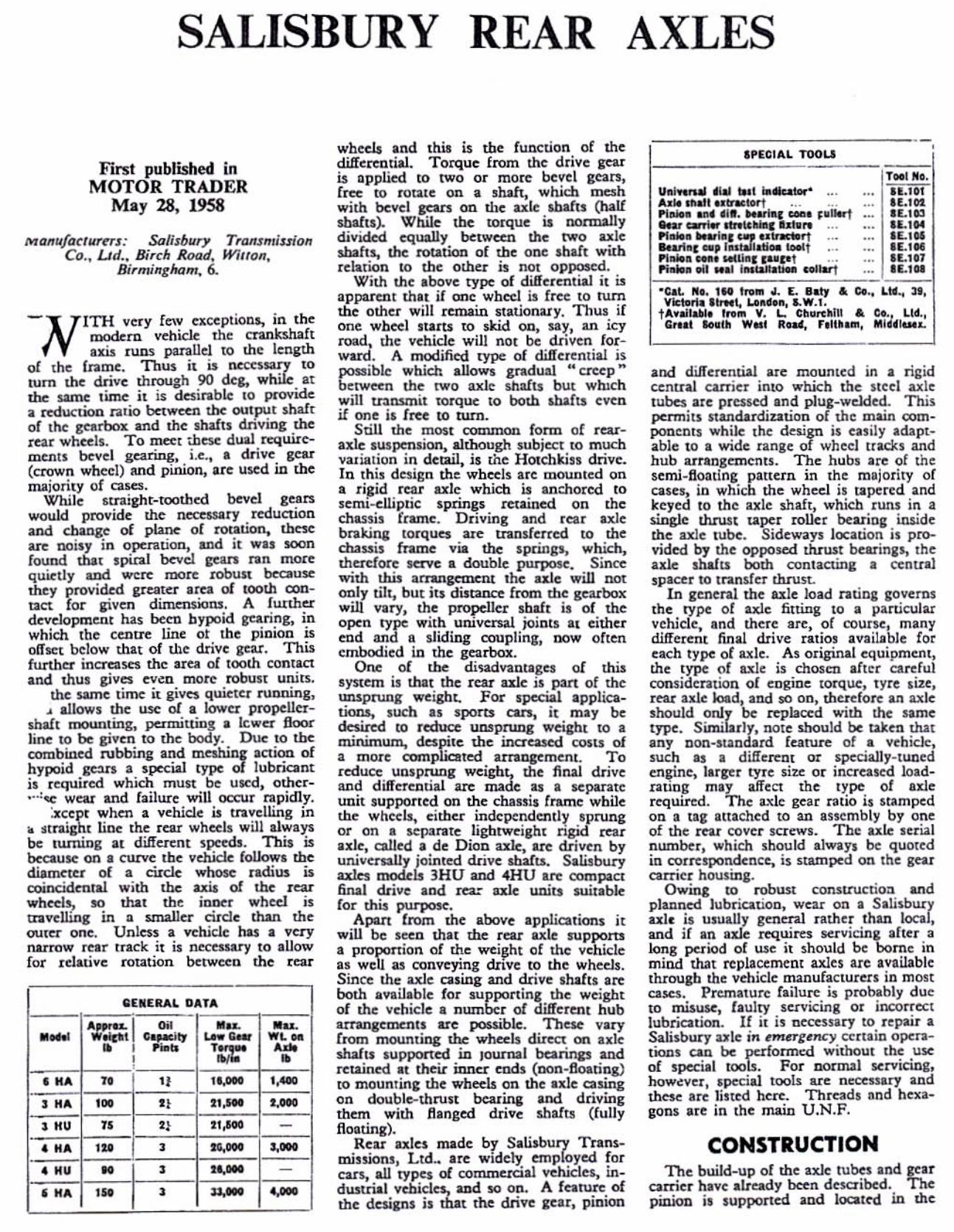
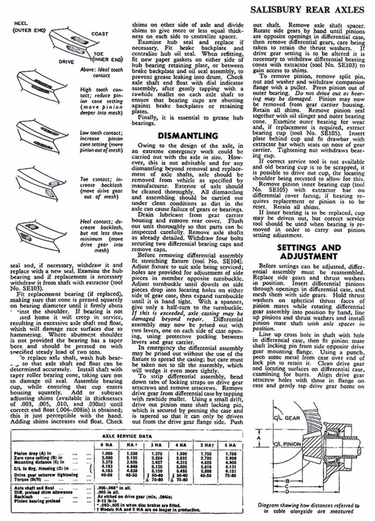
Aboo-~ : Idl<ll fOOlIt
COtlfDCl
"#,11 looth c_ (Q"; ,cdcK~ pi,.. iOfl <one Ullklt (mo~e pinion tk~per InlO mtsh)
low COQJh conlOCI; itl<ltoU plnl(WI COlIC stuift, (mO¥c pinion CMlt of mcsh)
TK (""toC!; ;... ((Nit bo<,tIOlh (_c o,j~e fcoI
CMIt of mesh)
Hffl (",,(Qee: de(mise llad./osll. but 110( Icn rho" m,nllTMlm (move et';Ye reo. /nib
mesh)
sui and, if rKCnsary, wilhdnw it and npbce with .. new seal. Examine the: hub bearing and if uplacement is nccess:lry whhdnw it from mafl with ('I(\I'II tlOI (100]
No. SEI03), __ = Fit IcplacUlKnl
making sun: Ihat cone on bearing diameter . -ins! the shoulder.
J$«I home it will resulting in acessive which will damage hammering. Where: is not provided the bore: and should be sf'tcified steady load
'0 replace IIXI~
. . .. $0 Ihat axle dcu~rmined
"pcr roller 10 dam:q:c _;',,,;;; CUP. while ' housing ad,uSling of .00], corrcct ' ." __ Ihis is Adding
I 1'lotI ... IIttf (A) I~ ... z .... c"" ' Mrlinr (_) In . .... 11.' "' .... " (C) I.
." --- ------ ---
elL tD SrI. " .... .., IDJ In •..
------
--- -----. --- --. ... . .. ,.. .... ---
sbims on olber side of nle and divide shims to s,ive more or less equal 1l'Ud:_ ncu on udl $.ide to <;(lIualae spacer.
P.xamine hub seal and t<:plaoe if n<:<:~ry. fit bn.ke baclcpllc( and cenUllJ.ize bub \lil IUI. Wbca rdilting, fit n(w P'p<:r gas);(ts on (ilher ,idc oC hub bearing retl'lini.nj: platc. or belwo:en brake bacl<pbte :md oil sui a»<:mbly, 10
prevent pcase leaking inlO dnun. Check aue $hall cnd Roal with dial indicalor usembly. afler gently lapping with a rawhide m.llet on each :llde shaft to ensure that bearing WJ)$ arc abutting against brake bacltplltcs or tctaining platc:s.
f inally. it is <:SS(nrial 10 grease hub bearifl2$.
DISMANTLING Owing 10 th( dnign of the: ulc, in
an cntut'le em<:f1l;ency wotk could bc carried OUI with the .,..te in sitl', How· ever. this is nOI advilllble Ind for .ny di$maniling beyond remov:iiI and replaoe· ment of wc shafts, axle should b~
removed from vch.icl~ ;)s sp<:<:ified by manuf:l<:tUt<:r. Extcrior 0( axle should be dc;)ned thoroughly. AU dismanthng and assembling should be ea.rtied out lmder c1enn condil ions u din in the IIJtle can cause failluc of curs or bearin;s.
Du';n lubri(JInt ftorn gur camer housing and remove r~r cover. Fhl$h OUI urUI thoroughly $() Ihnt puts can be inspttloo c:udull,. Removc axle ,h3fts as a l ~y detailed. 'Witbdtaw fout bolu $«Uring tWO diffcrential bearing caps and reDlOve caps.
Before removing dilferentw nscmbly fit Itretching fixture (tool No. 5EI(4). Adjl»t fixtur( to swt ",Ic !)cing scrvioed; holes :lI( provided tOt adjuntncm ot sidc p ieces in member opposi{c turnbl.ld:le. Adjl»1 turnbud:1e until dowels on side pie<:cs drop uno locating holes on either side 0( scar dI$C, then el(pand !urnbU<:kle uotil it is hand tight. With a spanner, give only .. half-turn to !he lumbuckle. 1/ thiJ ;1 l1«nckd, axil (4S,i"K mQ')' ~
dlml41ld ~)'01Id rtpair. Dilfctential assembly may now be: prised OUt with tWO kvers. onc on each SIde of C1SC open· iog, usiog pJ'Ol«'llVC pxking between levcl'l aod gear carrier.
In eme'Jency the dif{ctcnti31 a5SCmbly lNy be posed OUt \\;Ihout the: use of Ihe fuau re 10 sprcad the cuing; bue care mu$.! be uken nOI to tilt the assembly. which will walg( it cven more: tightly.
To ~Iri p di{fermnal uscrnbly, bend down ta~ of Iocl:irli StTJPS on drive gCIf setscrews and remove $Ct5Crewl. Remove drive scar from diffcfCntial case by tapping wilh ",whide mallet . Using a small doff, driVe OUt piruon mate shlfl locking pin, which is secured by pecning thc cue and is tapered so tNI it an only be: driven out from !he drivc gear !tange side. Push
SALISBURY REAR AXLES
OUt shaft. Remove axk: sluf! Jp.Ctr. Rolate si~e scars. by ~ until ptIIions arc oppcKlle O~lngs III dllfuential casc, then remove di/felential gears, ale being 11ltco to retain rhe thrust washcf'$. If drive gear setting is to be altered it is neasSJry [0 witbdt:aw d.iff(rential belling co~e:s WIth (1001 N o. SE103) to pm :lOCUS to
To
replac<:d, cup coercel servicc bearing is re
to (:Iny out pinion
SETTINGS AND ADJUSTMENT
Before scltings can be adjUSfcd, differ. ential a$$Cmbly mUSI be rC3Sscmbled. Replace side gears and [hruS! washu$ io position. Inscrt diffe rential pinions through openings in diffetential case, and mesh ,hem with side leafS. H old. Ihrull wlShen on spherical thOUt f;)CCs of pinion IIllItes while rOlacing differerllia l gear . a~mb l y into position by hand, line up plluons and thrust wuheu and innall PlruOll mate sluh with (lx/c spactr ill petinon.
Une up <:cou hole in $haf, with hole in differrntial case, ~hen fi~ pinion mite :\hafl lockiDJt pin (rom side opposite drive gecr.r mounting flange. Using 11 punch, peen some /TIC'ta l from case over cnd of lock pin .to retain it . a~an drive ilear lmd I~flng ~Ulfa c n on diff(rcnt i) 1 case, cxa,rn;nil'lg for burN. Align drive gear setscrew holes with thn.\<: in flange on case and tently lip drive gur home on
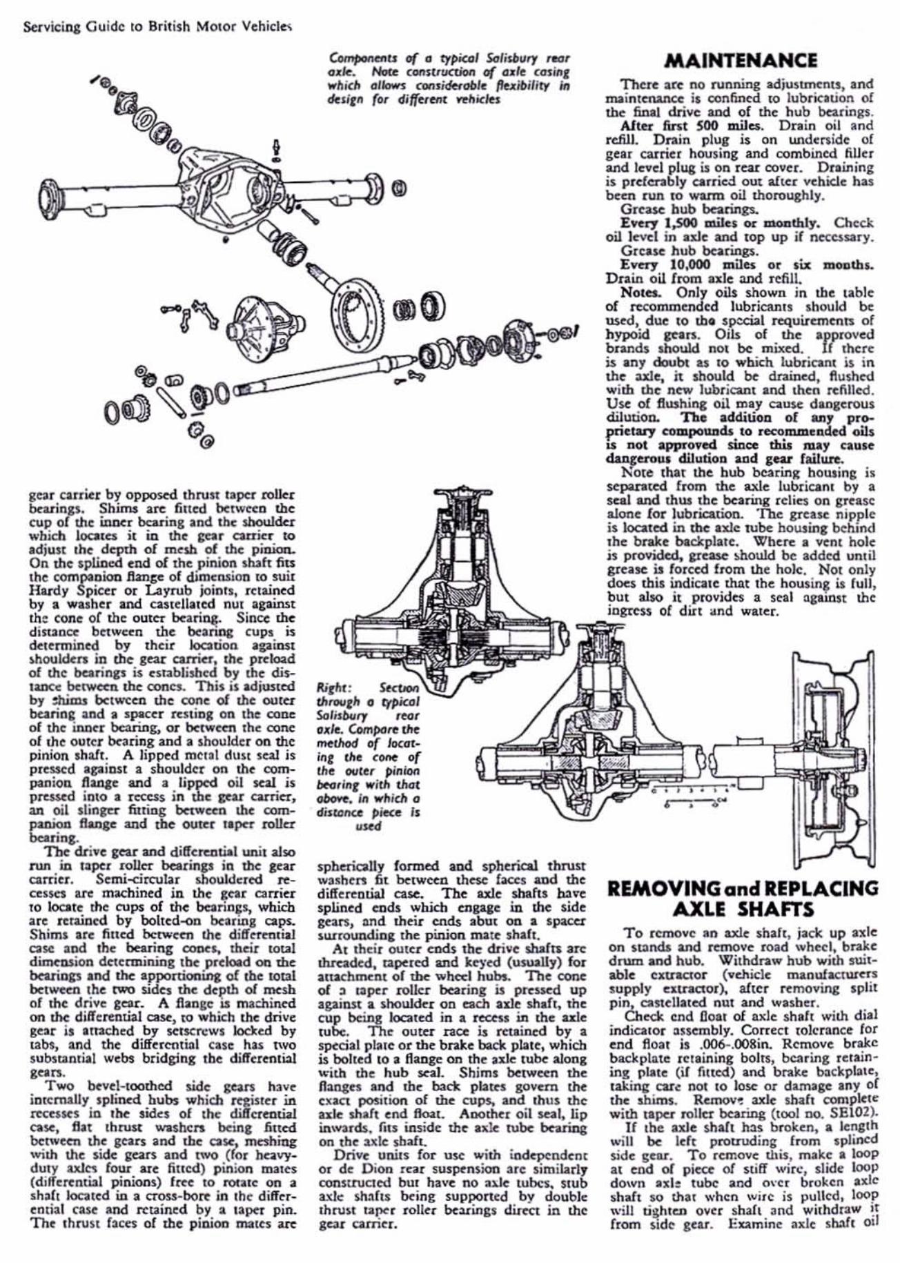
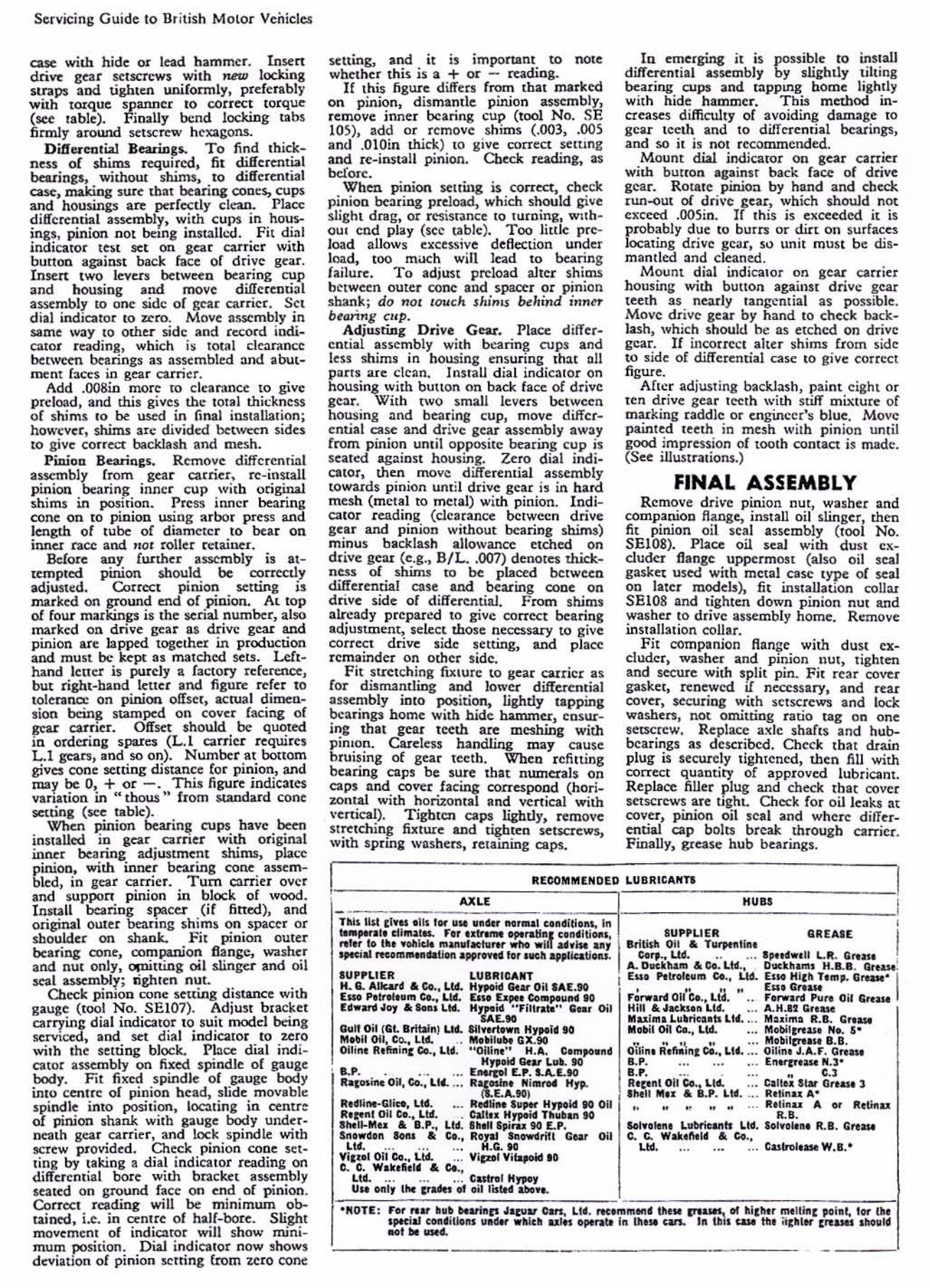
~GEAR T -1---._-A
. I
Oior,om IhowiAr how di1tollCU rt(e(((d 10 ill 'ob/( (l1011rJIIk ot<: mc4111rM
Servicing Guide to British MOlor Venieles
cue wilh hide or lead hammer. lnsen dri...: gear setscrews wi th new locking SlIa", and tighten uni fonnly, preferably woh 100<!.ue spanner to corr«t torque (sec table). Finally \x:nd locking tabs firmly around setscrew hexagons.
D if( uetl tw Bearings. To find Ihiekne55 of shims requi red, fi t differential bca.ringl, without shim" 10 di fferential case, making sure that bearing conc$, cups and housings are p.:d«t1y dt:an. Plaa: diffe rential assembly, with cups in housings, pin ion nOI bemg insulkd. Fit di~l indicator test set on gear carrier with button agailllit back haec of d rive gear. Insert twO levers between bearing cup and housing and move difle rcntia l a~mbly to one side o f gear carrier. Set d ial indicator to zero. Move a!;S(mbly in $l.me way to other sidc and record indicatOl readinJl, which is lotal deamncc between bearings a1 assembled and abutment fae<cs in gear carrier.
Add .000in more 10 clear.mee to give prd oad, and this gives the 10lal thi<;kness of shims 10 be used in final installation; how~v er , shims arc div ided between sides to give eorrect: backlash and mesh.
P inioo Bearings. Remove differenlial assembly from gear carrier, re- inSlall pinion bearing inner cup with odgirul shims in position. Press inner bearin!; cone on [ 0 pinion using arbor pren and length of tube of diameter to bear on inner race and "Qr roller ro:laiocI .
& (Qre any further assembly is .ttempted pinion should be oorrcclly adjusted. Correct plfUOD setting is marked OD (:TOund end of 'pinion. At top of four mukings is the scrlal number, abo marked on d rive gnr as dti v ~ geas: and pinion are lapped toge rhel in production and must be kept as matched sel!. Le!thand letter is pulcly a factory reference, but right-halld lelle r and figure refer to tolerance on pinion offset, actua l dimcosion bcin~ stamped on COVer facing of gear carner. Offset should be QUOted io ordering lparO (L.1 carrier requi res L.l gears, and 50 on). N umber at bonom givC$ cone setting distance for pinion, and maf be 0, + or -. This figure indiellles van llion in "thous" from standard cone setting (sce tabk).
When pinion bc ar in~ cups have been inslalled io gear earner with odginal inner bc~ ri ng adjustment shims, plae<c pinion, with inocr bearing C{)uc assembled, in gear carrie r. T um (:Irrier over and suppon pinion in block of wood. Insta ll bearing spaeer (if fined), and original OUler bearing shims on spacer or shoulder on :;bank. Fit pinion outer be. ri ng: cone, mmpanion flange, w;t:;ber and nut ol1ly, OPli tting oi l slinger and oil ~l assembly; lighten nut.
Check pinion cone Setl ing distance with gauge (tool No. SEI07). Adjust bracket carrying dia l irnlicalOr to sui t model being serviced, and set di~1 indicator to UfO
wilh the setting: block. Pbce dial indi_ cator assembly on fixed spindle of gauge body. Fit fi Ked spindle of gauge body intO eenue of pinion head, slide movable spindle into position, locating in centre of pinion shank with gauge body underneath gear carr ier, and lock spindle wilh !Crew provided. Check pinion colle sctti ng by taking a d ial indicalor reading on di fferentia l bore with bracket as&embly $Cated on ground face on end of pinion. CorrCoC t reading will be minimum obuiDC<l, i.e. in <;cnrre o f half_bore. S lighl movemenr of indicator will shov.· mini_ mum position. Dial indicator now shows deviation of pinion loCu ing from uro cone
setting, and it is important to note whether this is a + or - reading.
If this figure differs from tbat marked on pinion, di, mantle p inion assemhly, remove inner bearing cup (tool No. SE 105), add or remove sh ims (.003, .005 and .010in thick) to give correct selting and rc-install pinion. Ch«:k reading, as before.
When pinion senolg is correct:, check pinioll bearing pteload, which should give slight drag, or resistance to turn ing, wuh_ OUI cnd play (sce table). T oo little preload allows eo<eess;ve d eHc:ction under load, tOO mach will lead 10 bearing failure. To adjust prdoad al ter shims between outer cone and spacer or pinion shank; do '10! lOUGh Jhi"'$ behind jn "C>' bronng Clip.
Adjusting Drive Gear. Place differential assembly wi th bearing cups and less shims in housing emuring that oil parts a re clean. Install d ial ind icator on housing with bunon on back face of drive gear. With twO small levers between housing and hearing cup, move differential case and drive gear assembly aW;J;y from pinion until opposite bearing cup is seued against housing. Zero dial indica tor, then m ov~ differential assembly towards p inion until drive gear is in ha rd mesh (metal to metal) with pinion. Indicator reading (clearane<c between drive gear and pinion without bearing sbims) minus backlash allowance etched on drive geu (e.g., S/L .. 007) denotes thickneM of shinu to be placed belweeo differential case .nd bearing cone on drive side of diffe rential. From shims aJ.n:ady prepared 10 give corr«t hearillg adjustment, select those nccessuy to give C{)rrcct drive side setting, and place remainder on other side.
Fit slretching flll lure 10 gear carrier as Cor dismamling and lowCl' d ifferential assembly ioto position, lightly lapping bearings home with hidc hammCJ:, ensurin;: mal gear teeth are meshing with pimon. Careless handling m ay cause hwising of gear teeth. Wbeo rcfitting bearing cap s be sUle that ntunerals on caps and covet facing correspond (hori_ zontal with hOrU:on tal and vertical with \·ertical). T ighten caps lightly, remove stretching fixture and tighten setscrews, with spr ing washers, retaining ClIps.
In emerging it is possible to in"all differentia l assembly by sli;:htly tilting hearing cups and tappmg home lightly with hide hammer. This method increases difficulty of avoiding damage to gear tee!h and to differential bcaring1, and so it is nOI recommended.
Mount dial indicator on gear carrier with butlon .gainsr back face of drive gear. RotalC pinion by hand and cbeck run-oUt of dri,'c gear, which should not CKcced .005in. If this is eKcceded it is probably due to burrs or dirt On surfaces locating drive gear, so unit must be dismant led and cleaned.
Mount d ial indicator on gear carrier housing with button against driVe gear teelh $S nearly tang,'ntial as possible. Move drive gear by hand to eheck back_ lash, which shouW he as etched on drive gear. If incOtrC<.:t alter shims from side to side of differential case 10 give eOHect ligwe.
Afl ~ r adjusting baclUash, paint eight or ten drive gear leeth with stiff mixture of marking raddle or engineer's blue. Move painted leeth in mesh with pin ion until good impression of tooth contact is made. (Sce illust rations.)
FINAL ASSEMBLY Remove dr;"e pinion nUl, washer and
compauion flange, install oil ilinger, then fit pinion oil seal assembly (tool No. SE lOg). PJace oil seal with dust ex_ cluder flangc uppermost (also oil scal gask« used with meta l case Iype of ~a l
on latcr models), fi t installation C{)llaJ SE lOS and tighten down pin ion nut and washer to drive assembly home. R~move
installation collar. F it companion Hange with dust ex
cluder, washer and pinion nut, tighlen and secure with sp'lit pin. Fit rear cover gasket, renewed if necessary, and rear cover, securing with setscre"'ll and lock washers, not omiuing ratio tag on <lne set$Crew. Replace axle shafts and hubbearings as dcscribed. O:.eck tbat drain plug is secUl1:ly tIghtened, then fill with correct quantity of approved lubricam. Replace filler plug and check that cover S«SCTCWS are tiQ:hL Check {or oil leak5 at cover, pinion oil seal and where differ_ ential cap bolts break th rough tarrier. F inally, grease hub bearings.
k[COMfIltNDEII LU BRlCANn
"". --Tills 1111 ,I. ", . H. 'Of ~ ... ,,111, ........ 1 "" " dit l l ~" In to .. , . .. t •• U ..... I ... roe .. _ .,. taII .' .'~"tiOlll, .. ltr to 1_. yolllclo .......... "' ... _.i u . .... , ..... '" reQlOI_oIaU." lpp<_ hlr otIClt .",,! .. II~
Gull Oi' ISL BrIt11nl u-. M..,lt 0;1, Co., lt4.. .. Olli ... 1I,1\IIi .. ( Co., It • .
. "'P. . .... ltlpsi ... O ~, Co., lU, ...
II,~ ~",· SI ,", Uf . It.tonl 0;1 to., L ~
HUBS
, """ T.,..lnI 011 to., Ltd. Hilt .JiKlt •• • Ltd. fII w "" Lg_rt . .. tI LI( . ... fIIlbilOll eo., Ltot.
o'ili". R '.~\nl r;., L'(. ::: II.P. .. . • .. II.P. . 1I0p nt 011 Co., LI .. .""" 1111.. • '.P. l tl . ...
QatAI[
81Nt1-M ... B . P ~ Lt~ . ", .. d... ....... '" eo., ':: t n ~ . L ~:"; L ~: " :i~£ ~ 11.'. G .....
Oil e. e. W"ol'tol' • eo.. I, L ~ , .. LIII. ... ... .. . Cntrolo .. W.I .'
Vi, .. t O~ Co., Lld. C. C. Wak,fi,14 • Co.,
Ltd.... ... ... 1:",,,,,1 H"", U .. ont, I'" (u,," of ,,;Ilislo<l ......
'----- - - - - - -- - - -