Embed Size (px)
Citation preview
Istituto di Geoscienze e Georisorse – IGG
Area Ricerca CNR di Pisa - via G. Moruzzi, 1 - 56124 Pisa
Sampling and analysis procedure for calculating
hydrogen sulphide leaving cooling towers in geothermal power stations
IGG/CNR-4 METHOD
(M4)
Authors: Alessandro Lenzi2, Antonio Caprai1, Marco Paci2, Romina Taccone2, Alessandro Bettini2,
Antonio Ciompi4
In collaboration with ARPAT - Geothermal Sector, ARPAT Laboratory Sector AVS Siena3
1C.N.R.- National Research Council,
Institute of Geo-Sciences and Geo-Resources
2Enel Green Power
Coordinated by: Antonio Caprai CNR-IGG
Method: IGG/CNR -4 (M4) Rev: 0 Edition: 14.06.2018
IGG/CNR-4 METHOD
2
CONTENTS
1. PURPOSE AND SCOPE OF APPLICATION .................................................................................................... 4
2. REFERENCE DOCUMENTS .......................................................................................................................... 4
3. TERMS AND DEFINITIONS .......................................................................................................................... 4
4. PRINCIPLE .................................................................................................................................................. 5
5. SAMPLING EQUIPMENT ............................................................................................................................. 6
5.1 SAMPLING CONDITIONS ........................................................................................................................ 6
5.2 GENERAL REQUIREMENTS ..................................................................................................................... 6
5.3 SAMPLING EQUIPMENT ......................................................................................................................... 7
5.4 ABSORBERS ............................................................................................................................................ 8
5.5 CONNECTIONS ....................................................................................................................................... 8
5.6 STORAGE FLASKS AND CONTAINERS ...................................................................................................... 8
5.7 MATERIALS FOR SAMPLING EQUIPMENT .............................................................................................. 8
5.8 SUCTION UNIT ....................................................................................................................................... 9
5.9 GAS VOLUME MEASURING UNIT ........................................................................................................... 9
6. REAGENTS .............................................................................................................................................. 9
6.1 GENERAL INFORMATION ....................................................................................................................... 9
6.2 REAGENTS FOR PRE-CLEANING OF SAMPLING EQUIPMENT .............................................................. 10
6.3 SELECTING ABSORPTION SOLUTIONS .................................................................................................. 10
6.3.1 General Information ........................................................................................................................ 10
6.3.2 Zinc acetate absorption solution 0.05 (11 g/L expressed as (CH3COO)2Zn) .................................... 10
6.3.3 Standard solution I2 0.1N................................................................................................................... 10
6.3.4 Standard solution Na2S2O3 0.1N ......................................................................................................... 10
6.3.5 HCl solution 1:2 .................................................................................................................................. 10
6.3.6 Starch solution ................................................................................................................................... 10
6.3.7 NaOH solution 6M .............................................................................................................................. 11
6.3.8 Absorption solution for NH3 ............................................................................................................... 11
6.4 REAGENTS FOR RINSING THE SAMPLING LINE AFTER SAMPLING ....................................................... 11
6.4.1 Solution of HNO3, 10%m/m ............................................................................................................. 11
7. PROCEDURE ......................................................................................................................................... 11
7.1 GENERAL REQUIREMENTS ................................................................................................................... 11
IGG/CNR-4 METHOD
3
7.2 PRE-CLEANING THE EQUIPMENT ......................................................................................................... 11
7.3 PREPARING AND INSTALLING THE EQUIPMENT .................................................................................. 12
7.3.1 Installing the absorbers ................................................................................................................... 12
7.3.2 Seal tests .......................................................................................................................................... 12
7.3.3 Installing the equipment in the sampling position .......................................................................... 12
7.4 SAMPLING ............................................................................................................................................ 13
7.5 DISMANTLING THE EQUIPMENT.......................................................................................................... 13
7.5.1 Rinse the connection pipes on the first absorber ........................................................................... 13
7.5.2 Collecting absorption solutions from absorbers ............................................................................. 13
7.5.3 Rinsing the sampling equipment .................................................................................................... 14
7.6 SAMPLE STORAGE REQUIREMENTS .................................................................................................... 14
7.7 ANALYSIS .............................................................................................................................................. 14
7.7.1 Field analysis procedure - protocol 1 ................................................................................................. 14
7.7.2 Laboratory analysis procedure - protocol 2 ....................................................................................... 15
7.7.3 Calculating the amount of H2S in the absorption solution ................................................................ 15
8. REPORTING THE RESULTS ..................................................................................................................... 16
8.1 HYDROGEN SULPHIDE CONTENT ........................................................................................................ 16
8.2 VOLUME OF GAS UNDER REFERENCE CONDITIONS ........................................................................ 16
8.3 CALCULATING THE GAS FLOW FROM THE COOLING TOWERS .......................................................... 17
8.4 ACCEPTANCE OF REPETITIONS .......................................................................................................... 17
8.5 PERFORMANCE CHARACTERISTICS .................................................................................................... 17
9. TEST REPORT ........................................................................................................................................ 18
APPENDIX A: SAMPLING EQUIPMENT CLEANING PROCEDURE ...................................................................... 19
APPENDIX B: ACCEPTANCE OF REPETITION DATA (THREE REPETITIONS IN PARALLEL) ................................... 20
APPENDIX C: ISO-KINETIC, TIMELY AND ACCUMULATIVE SAMPLING: SAMPLING PARAMETER SELECTION
CRITERIA .......................................................................................................................................................... 23
IGG/CNR-4 METHOD
4
Sampling and analysis procedure for calculating hydrogen sulphide leaving cooling
towers in geothermal power stations.
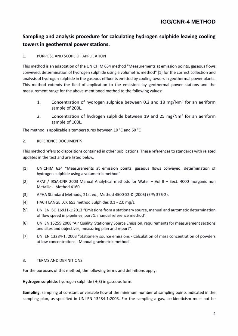
1. PURPOSE AND SCOPE OF APPLICATION
This method is an adaptation of the UNICHIM 634 method "Measurements at emission points, gaseous flows
conveyed, determination of hydrogen sulphide using a volumetric method" [1] for the correct collection and
analysis of hydrogen sulphide in the gaseous effluents emitted by cooling towers in geothermal power plants.
This method extends the field of application to the emissions by geothermal power stations and the
measurement range for the above-mentioned method to the following values:
1. Concentration of hydrogen sulphide between 0.2 and 18 mg/Nm3 for an aeriform sample of 200L.
2. Concentration of hydrogen sulphide between 19 and 25 mg/Nm3 for an aeriform sample of 100L.
The method is applicable a temperatures between 10 °C and 60 °C
2. REFERENCE DOCUMENTS
This method refers to dispositions contained in other publications. These references to standards with related
updates in the text and are listed below.
[1] UNICHIM 634 “Measurements at emission points, gaseous flows conveyed, determination of hydrogen sulphide using a volumetric method"
[2] APAT / IRSA-CNR 2003 Manual Analytical methods for Water – Vol II – Sect. 4000 Inorganic non Metallic – Method 4160
[3] APHA Standard Methods, 21st ed., Method 4500-S2-D (2005) (EPA 376-2).
[4] HACH LANGE LCK 653 method Sulphides 0.1 - 2.0 mg/L
[5] UNI EN ISO 16911-1:2013 “Emissions from a stationary source, manual and automatic determination of flow speed in pipelines, part 1: manual reference method”.
[6] UNI EN 15259:2008 “Air Quality, Stationary Source Emission, requirements for measurement sections and sites and objectives, measuring plan and report”.
[7] UNI EN 13284-1: 2003 “Stationery source emissions - Calculation of mass concentration of powders at low concentrations - Manual gravimetric method".
3. TERMS AND DEFINITIONS
For the purposes of this method, the following terms and definitions apply:
Hydrogen sulphide: hydrogen sulphide (H2S) in gaseous form.
Sampling: sampling at constant or variable flow at the minimum number of sampling points indicated in the
sampling plan, as specified in UNI EN 13284-1:2003. For the sampling a gas, iso-kineticism must not be
IGG/CNR-4 METHOD
5
guaranteed because the substance of interest is not present either as solid particulate or in droplets.
Absorber: IMPINGER type device in which gaseous hydrogen sulphide is absorbed by an absorption solution.
Drift: drops of water circulating in the cooling tower that become incorporated into the air flow from the
tower and emitted into the atmosphere
Cell: portion of an forced draught cooling tower equipped with a fan and walls sending air out of the tower
which can be considered as an elementary emitter. In the case of a natural draught tower, the cell is made up
of the tower itself
4. PRINCIPLE
The fluid is sampled near the cooling tower outlet mouth using a probe connected to teflon pipes to convey
the sampled gas to the absorbers. There is no dry solid particulate in the cooling tower effluent of geothermal
plant, so that it is not necessary to use a filter in the sampling system. Three absorbers are used: the first is
empty to collect the condensing vapour and drift; the second and third contain the hydrogen sulphide capture
solution based on zinc [Zn(CH3COO)2].
A sample flow of gas effluent is extracted in a representative manner from the stack of one of the coolant
tower cells for a given period of time at a controlled flow rate of no more than 2L/min and volume between
100L and 250L.
At the end of the sampling period, the absorption solution is collected and can be analysed immediately.
Alternatively, the solution can be analysed in the laboratory after alkaline stabilization. In this case, the
analytical determination must be performed within two weeks of taking the sample.
Sampling and analysis data are combined and the results are expressed in milligrams of hydrogen sulphide
per harmonised cubic meter (mg/Nm3) of dry gaseous effluent.
The analysis of hydrogen sulphide can be performed in accordance with the analytical protocols of the
UNICHIM Method 634, integrated with APHA Standard Methods, 21st ed. Method 4500-S2-D (2005) (EPA
376-2).
The flow rate measured refers to the aeriform moisture at the temperature and pressure conditions of the
tower at the sampling point; the dry to wet correction is calculated by assuming that the aeriform on output
from the tower is in saturation conditions (the error introduced by this approximation is negligible compared
to the flow measurement error). This correction is necessary because the analytical concentration measured
in the field is related to dry gas.
5. SAMPLING EQUIPMENT
5.1 SAMPLING CONDITIONS
If a gas injection point different from the one sampled is present at the measuring cell (for example gas from
the gas extractor outlet and from the AMIS plant outlet), sampling must be carried out at a sufficient distance
from the gas inlet point in order to avoid interference with the amount of analyte taken. For samples taken
IGG/CNR-4 METHOD
6
from forced draught towers comprising several cells, sampling must be carried out in a cell not affected by
the introduction of gas (by closing the valve on the gas supply pipe to the cell itself).
5.2 GENERAL REQUIREMENTS
The sampling equipment comprises:
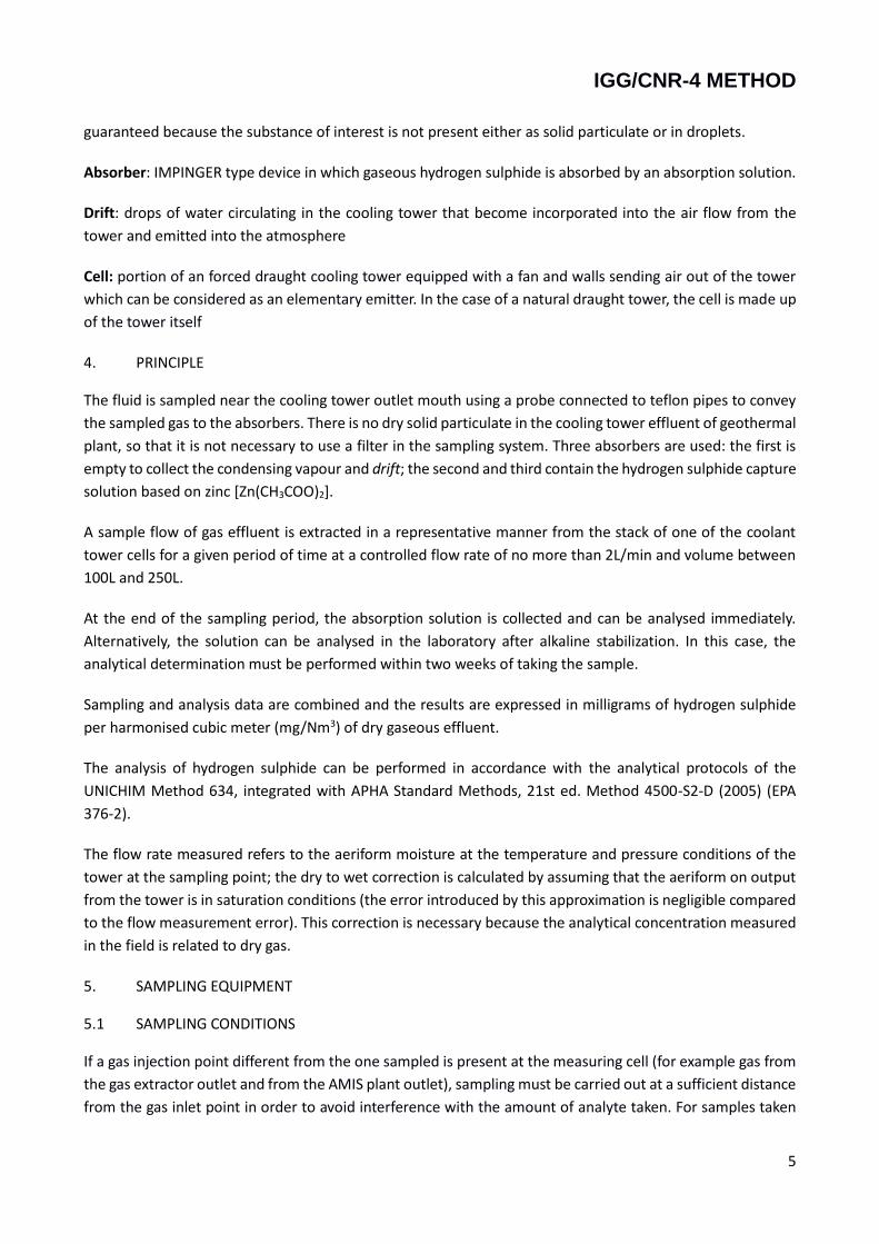
1. A probe with Teflon tubes 10mm in diameter. For this application an uncontrolled and no-nozzle temperature probe is used. The probe is not thermostat-controlled because the temperature of the sampled gases is similar to ambient temperature.
2. Gas absorption line made up a series of absorbers (absorber 1 empty, absorbers 2 and 3 used for 100 ml of zinc acetate absorption solution).
3. Silica gel to eliminate residual moisture
4. A suction pump to ensure the required flow of sampled gas (2L/min). This pump must be fitted with a volumetric (positive displacement) meter to quantify the volume of sampled gas (150L - 250L).
Figure 1 - Sampling system used for taking samples of hydrogen sulphide.
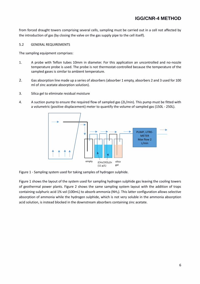
Figure 1 shows the layout of the system used for sampling hydrogen sulphide gas leaving the cooling towers
of geothermal power plants. Figure 2 shows the same sampling system layout with the addition of traps
containing sulphuric acid 1% vol (100mL) to absorb ammonia (NH3). This latter configuration allows selective
absorption of ammonia while the hydrogen sulphide, which is not very soluble in the ammonia absorption
acid solution, is instead blocked in the downstream absorbers containing zinc acetate.
PUMP, LITRE-METER
Max flow 2 L/min
(CH3COO)2Zn (11 g/L)
silica gel
empty
IGG/CNR-4 METHOD
7
Figure 2 – Sampling system used for taking samples of ammonia (NH3) and hydrogen sulphide (H2S).
5.3 SAMPLING EQUIPMENT
The equipment includes a non-heated sampling probe in one of the materials listed in paragraph 5.7
5.4 ABSORBERS
To ensure efficient collection, absorbers must be positioned in series. An additional vacuum absorber (volume
about 250ml) is used up-line of these absorbers as a condensation trap.
5.5 CONNECTIONS
Guidance concerning the choice of materials for connections between the different parts of the sampling
equipment is provided in paragraph 5.7 and must be applied for parts in contact with the gaseous effluent
containing hydrogen sulphide.
The silicon connections connecting the various traps should be short and the surface in contact with the fluid
should be less than 2 cm 2 for each coupling.
5.6 STORAGE FLASKS AND CONTAINERS
The material used for bottle storing absorption solutions is indicated in para 5.7. If laboratory analysis is
performed, storage bottles for the absorption solution (6.3.2) should be stored in a refrigerated area,
protected from light to avoid oxidation of H2S.
5.7 MATERIALS FOR SAMPLING EQUIPMENT
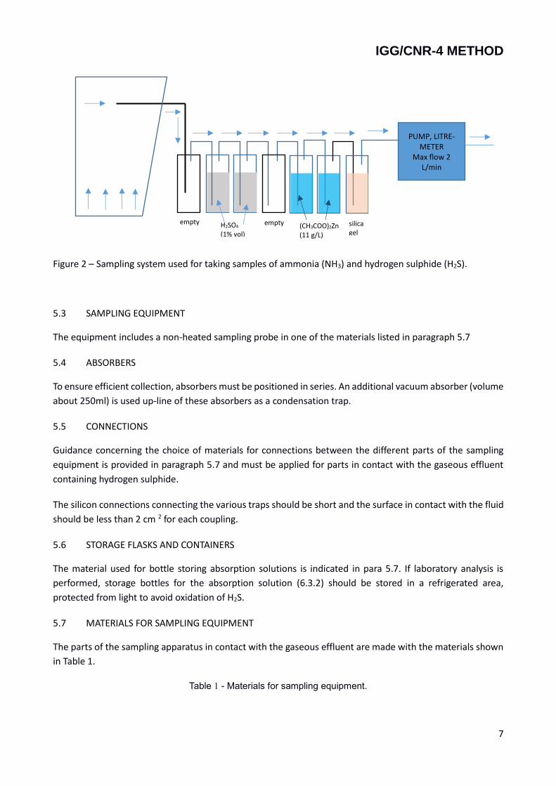
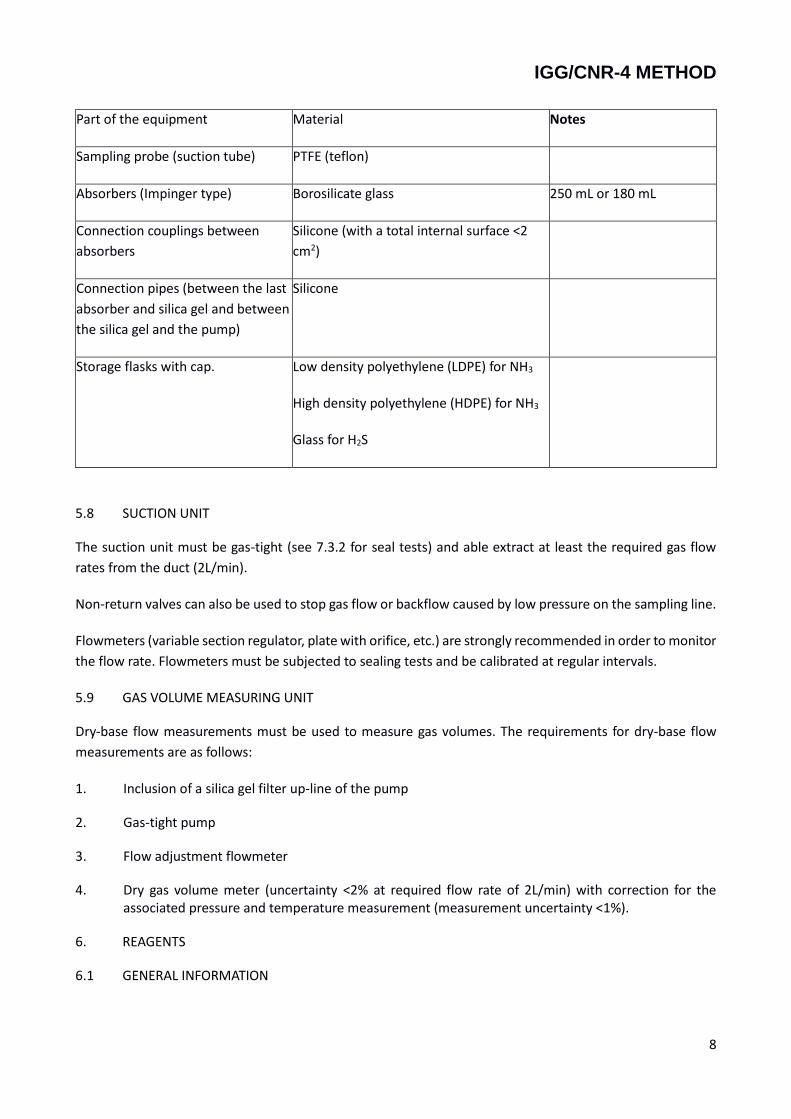
The parts of the sampling apparatus in contact with the gaseous effluent are made with the materials shown
in Table 1.
Table 1 - Materials for sampling equipment.
PUMP, LITRE-METER
Max flow 2 L/min
H2SO4 (1% vol)
empty empty (CH3COO)2Zn (11 g/L)
silica gel
IGG/CNR-4 METHOD
8
Part of the equipment Material Notes
Sampling probe (suction tube) PTFE (teflon)
Absorbers (Impinger type) Borosilicate glass 250 mL or 180 mL
Connection couplings between
absorbers
Silicone (with a total internal surface <2
cm2)
Connection pipes (between the last
absorber and silica gel and between
the silica gel and the pump)
Silicone
Storage flasks with cap. Low density polyethylene (LDPE) for NH3
High density polyethylene (HDPE) for NH3
Glass for H2S
5.8 SUCTION UNIT
The suction unit must be gas-tight (see 7.3.2 for seal tests) and able extract at least the required gas flow
rates from the duct (2L/min).
Non-return valves can also be used to stop gas flow or backflow caused by low pressure on the sampling line.
Flowmeters (variable section regulator, plate with orifice, etc.) are strongly recommended in order to monitor
the flow rate. Flowmeters must be subjected to sealing tests and be calibrated at regular intervals.
5.9 GAS VOLUME MEASURING UNIT
Dry-base flow measurements must be used to measure gas volumes. The requirements for dry-base flow
measurements are as follows:
1. Inclusion of a silica gel filter up-line of the pump
2. Gas-tight pump
3. Flow adjustment flowmeter
4. Dry gas volume meter (uncertainty <2% at required flow rate of 2L/min) with correction for the associated pressure and temperature measurement (measurement uncertainty <1%).
6. REAGENTS
6.1 GENERAL INFORMATION
IGG/CNR-4 METHOD
9
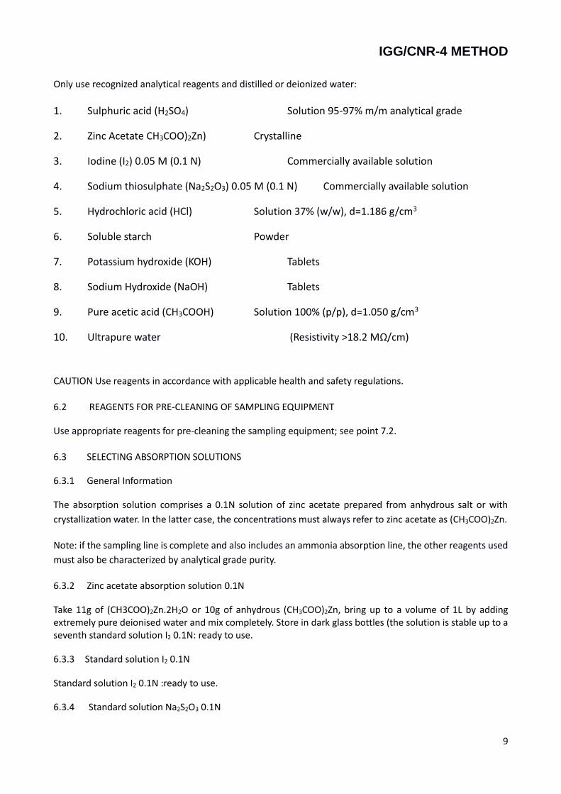
Only use recognized analytical reagents and distilled or deionized water:
1. Sulphuric acid (H2SO4) Solution 95-97% m/m analytical grade
2. Zinc Acetate CH3COO)2Zn) Crystalline
3. Iodine (I2) 0.05 M (0.1 N) Commercially available solution
4. Sodium thiosulphate (Na2S2O3) 0.05 M (0.1 N) Commercially available solution
5. Hydrochloric acid (HCl) Solution 37% (w/w), d=1.186 g/cm3
6. Soluble starch Powder
7. Potassium hydroxide (KOH) Tablets
8. Sodium Hydroxide (NaOH) Tablets
9. Pure acetic acid (CH3COOH) Solution 100% (p/p), d=1.050 g/cm3
10. Ultrapure water (Resistivity >18.2 MΩ/cm)
CAUTION Use reagents in accordance with applicable health and safety regulations.
6.2 REAGENTS FOR PRE-CLEANING OF SAMPLING EQUIPMENT
Use appropriate reagents for pre-cleaning the sampling equipment; see point 7.2.
6.3 SELECTING ABSORPTION SOLUTIONS
6.3.1 General Information
The absorption solution comprises a 0.1N solution of zinc acetate prepared from anhydrous salt or with
crystallization water. In the latter case, the concentrations must always refer to zinc acetate as (CH3COO)2Zn.
Note: if the sampling line is complete and also includes an ammonia absorption line, the other reagents used
must also be characterized by analytical grade purity.
6.3.2 Zinc acetate absorption solution 0.1N
Take 11g of (CH3COO)2Zn.2H2O or 10g of anhydrous (CH3COO)2Zn, bring up to a volume of 1L by adding extremely pure deionised water and mix completely. Store in dark glass bottles (the solution is stable up to a seventh standard solution I2 0.1N: ready to use.
6.3.3 Standard solution I2 0.1N
Standard solution I2 0.1N :ready to use.
6.3.4 Standard solution Na2S2O3 0.1N
IGG/CNR-4 METHOD
10
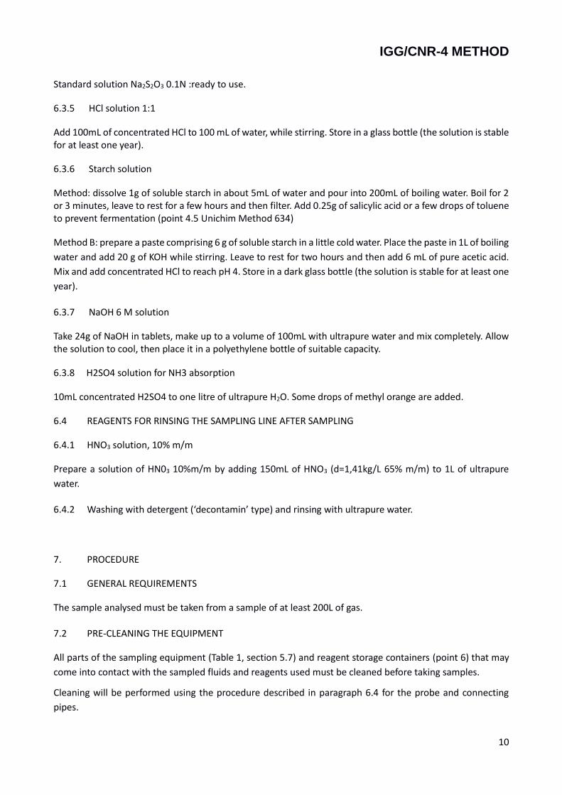
Standard solution Na2S2O3 0.1N :ready to use.
6.3.5 HCl solution 1:1
Add 100mL of concentrated HCl to 100 mL of water, while stirring. Store in a glass bottle (the solution is stable for at least one year).
6.3.6 Starch solution
Method: dissolve 1g of soluble starch in about 5mL of water and pour into 200mL of boiling water. Boil for 2 or 3 minutes, leave to rest for a few hours and then filter. Add 0.25g of salicylic acid or a few drops of toluene to prevent fermentation (point 4.5 Unichim Method 634)
Method B: prepare a paste comprising 6 g of soluble starch in a little cold water. Place the paste in 1L of boiling
water and add 20 g of KOH while stirring. Leave to rest for two hours and then add 6 mL of pure acetic acid.
Mix and add concentrated HCl to reach pH 4. Store in a dark glass bottle (the solution is stable for at least one
year).
6.3.7 NaOH 6 M solution
Take 24g of NaOH in tablets, make up to a volume of 100mL with ultrapure water and mix completely. Allow the solution to cool, then place it in a polyethylene bottle of suitable capacity.
6.3.8 H2SO4 solution for NH3 absorption
10mL concentrated H2SO4 to one litre of ultrapure H2O. Some drops of methyl orange are added.
6.4 REAGENTS FOR RINSING THE SAMPLING LINE AFTER SAMPLING
6.4.1 HNO3 solution, 10% m/m
Prepare a solution of HN03 10%m/m by adding 150mL of HNO3 (d=1,41kg/L 65% m/m) to 1L of ultrapure
water.
6.4.2 Washing with detergent (‘decontamin’ type) and rinsing with ultrapure water.
7. PROCEDURE
7.1 GENERAL REQUIREMENTS
The sample analysed must be taken from a sample of at least 200L of gas.
7.2 PRE-CLEANING THE EQUIPMENT
All parts of the sampling equipment (Table 1, section 5.7) and reagent storage containers (point 6) that may
come into contact with the sampled fluids and reagents used must be cleaned before taking samples.
Cleaning will be performed using the procedure described in paragraph 6.4 for the probe and connecting
pipes.
IGG/CNR-4 METHOD
11
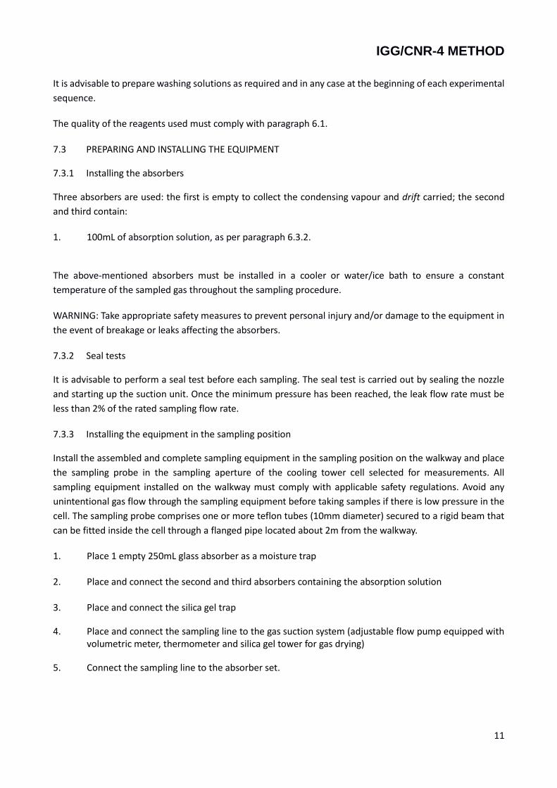
It is advisable to prepare washing solutions as required and in any case at the beginning of each experimental
sequence.
The quality of the reagents used must comply with paragraph 6.1.
7.3 PREPARING AND INSTALLING THE EQUIPMENT
7.3.1 Installing the absorbers
Three absorbers are used: the first is empty to collect the condensing vapour and drift carried; the second
and third contain:
1. 100mL of absorption solution, as per paragraph 6.3.2.
The above-mentioned absorbers must be installed in a cooler or water/ice bath to ensure a constant
temperature of the sampled gas throughout the sampling procedure.
WARNING: Take appropriate safety measures to prevent personal injury and/or damage to the equipment in
the event of breakage or leaks affecting the absorbers.
7.3.2 Seal tests
It is advisable to perform a seal test before each sampling. The seal test is carried out by sealing the nozzle
and starting up the suction unit. Once the minimum pressure has been reached, the leak flow rate must be
less than 2% of the rated sampling flow rate.
7.3.3 Installing the equipment in the sampling position
Install the assembled and complete sampling equipment in the sampling position on the walkway and place
the sampling probe in the sampling aperture of the cooling tower cell selected for measurements. All
sampling equipment installed on the walkway must comply with applicable safety regulations. Avoid any
unintentional gas flow through the sampling equipment before taking samples if there is low pressure in the
cell. The sampling probe comprises one or more teflon tubes (10mm diameter) secured to a rigid beam that
can be fitted inside the cell through a flanged pipe located about 2m from the walkway.
1. Place 1 empty 250mL glass absorber as a moisture trap
2. Place and connect the second and third absorbers containing the absorption solution
3. Place and connect the silica gel trap
4. Place and connect the sampling line to the gas suction system (adjustable flow pump equipped with volumetric meter, thermometer and silica gel tower for gas drying)
5. Connect the sampling line to the absorber set.
IGG/CNR-4 METHOD
12
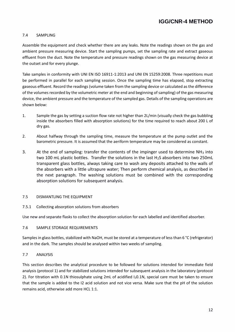
7.4 SAMPLING
Assemble the equipment and check whether there are any leaks. Note the readings shown on the gas and
ambient pressure measuring device. Start the sampling pumps, set the sampling rate and extract gaseous
effluent from the duct. Note the temperature and pressure readings shown on the gas measuring device at
the outset and for every plunge.
Take samples in conformity with UNI EN ISO 16911-1:2013 and UNI EN 15259:2008. Three repetitions must
be performed in parallel for each sampling session. Once the sampling time has elapsed, stop extracting
gaseous effluent. Record the readings (volume taken from the sampling device or calculated as the difference
of the volumes recorded by the volumetric meter at the end and beginning of sampling) of the gas measuring
device, the ambient pressure and the temperature of the sampled gas. Details of the sampling operations are
shown below:
1. Sample the gas by setting a suction flow rate not higher than 2L/min (visually check the gas bubbling inside the absorbers filled with absorption solutions) for the time required to reach about 200 L of dry gas.
2. About halfway through the sampling time, measure the temperature at the pump outlet and the barometric pressure. It is assumed that the aeriform temperature may be considered as constant.
3. At the end of sampling: transfer the contents of the impinger used to determine NH3 into two 100 mL plastic bottles. Transfer the solutions in the last H2S absorbers into two 250mL transparent glass bottles, always taking care to wash any deposits attached to the walls of the absorbers with a little ultrapure water; Then perform chemical analysis, as described in the next paragraph. The washing solutions must be combined with the corresponding absorption solutions for subsequent analysis.
7.5 DISMANTLING THE EQUIPMENT
7.5.1 Collecting absorption solutions from absorbers
Use new and separate flasks to collect the absorption solution for each labelled and identified absorber.
7.6 SAMPLE STORAGE REQUIREMENTS
Samples in glass bottles, stabilized with NaOH, must be stored at a temperature of less than 6 °C (refrigerator)
and in the dark. The samples should be analysed within two weeks of sampling.
7.7 ANALYSIS
This section describes the analytical procedure to be followed for solutions intended for immediate field
analysis (protocol 1) and for stabilized solutions intended for subsequent analysis in the laboratory (protocol
2). For titration with 0.1N thiosulphate using 2mL of acidified I20.1N, special care must be taken to ensure
that the sample is added to the I2 acid solution and not vice versa. Make sure that the pH of the solution
remains acid, otherwise add more HCL 1:1.
IGG/CNR-4 METHOD
13
7.7.1 Field analysis procedure - protocol 1
Separately analyse the portions from the absorption hydrogen sulphide (contents of the 2nd and 3rd
absorbers (5th and 6th absorbers in the event of simultaneous sampling of NH3) using the following
method:
1. Pour 2 ml of Iodine 0.1N and about 20mL of ultrapure water into a flask.
2. Acidify with approximately 2mL of HCl 1:1 and then add the first portion (2nd impinger), making
sure that the final pH of the solution is acid (with litmus paper).
3. Titrate any excess iodine with 0.1N sodium thiosulphate by adding about 0.3mL of starch solution
just before the colour change (pale straw yellow).
4. Perform the same measurement on the second portion (3rd impinger) and on 100mL of the
solution used for fixing (white).
NOTE: it is essential, in order to ensure that the iodine solution does not undergo non-acidic pH variations
and therefore generate iodide and hypoiodous acid, that the analysis solution is added to the iodine
solution.
7.7.2 Laboratory analysis procedure - protocol 2
If it is not possible to carry out titration immediately after sampling, each of the two portions containing
absorption solution as per 6.3.2 should be stabilized with 2 mL of NaOH 6 M (240 g/L). Then proceed as
described below:
1. Pour 2 ml of Iodine 0.1N and about 20mL of ultrapure water into a flask.
2. Acidify with approximately 5mL of HCl 1:1 and then add the first portion (2nd impinger), making
sure that the final pH of the solution is acid (with litmus paper).
3. Titrate any excess iodine with 0.1N sodium thiosulphate by adding about 0.3mL of starch solution
just before the colour change (pale straw yellow).
4. Perform the same measurement on the second portion (3rd impinger) and on 100mL of the
solution used for fixing (white).
NOTE: it is essential, in order to ensure that the iodine solution does not undergo non-acidic pH variations
and therefore generate iodide and hypoiodous acid, that the analysis solution is added to the iodine
solution.
7.7.3 Calculating the amount of H2S in the absorption solution
To calculate the amount of H2S in the absorption solutions, proceed as follows:
𝐻2𝑆𝑎𝑙1 = (𝑉𝑡𝑖𝑜𝑠.−𝑤ℎ𝑖𝑡𝑒 − 𝑉𝑡𝑖𝑜𝑠.𝑎𝑙1) ∗ 0.1 × 17.04
IGG/CNR-4 METHOD
14
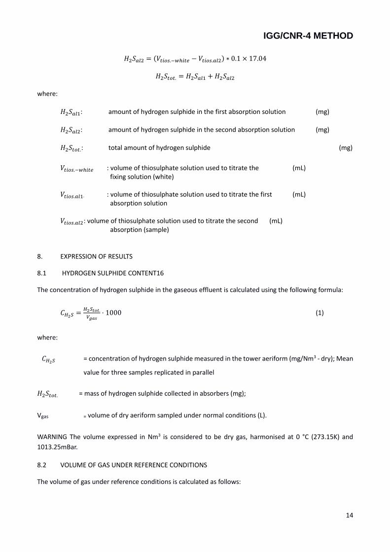
𝐻2𝑆𝑎𝑙2 = (𝑉𝑡𝑖𝑜𝑠.−𝑤ℎ𝑖𝑡𝑒 − 𝑉𝑡𝑖𝑜𝑠.𝑎𝑙2) ∗ 0.1 × 17.04
𝐻2𝑆𝑡𝑜𝑡. = 𝐻2𝑆𝑎𝑙1 +𝐻2𝑆𝑎𝑙2
where:
𝐻2𝑆𝑎𝑙1: amount of hydrogen sulphide in the first absorption solution (mg)
𝐻2𝑆𝑎𝑙2: amount of hydrogen sulphide in the second absorption solution (mg)
𝐻2𝑆𝑡𝑜𝑡.: total amount of hydrogen sulphide (mg)
𝑉𝑡𝑖𝑜𝑠.−𝑤ℎ𝑖𝑡𝑒 : volume of thiosulphate solution used to titrate the (mL) fixing solution (white)
𝑉𝑡𝑖𝑜𝑠.𝑎𝑙1. : volume of thiosulphate solution used to titrate the first (mL) absorption solution
𝑉𝑡𝑖𝑜𝑠.𝑎𝑙2 : volume of thiosulphate solution used to titrate the second (mL) absorption (sample)
8. EXPRESSION OF RESULTS
8.1 HYDROGEN SULPHIDE CONTENT16
The concentration of hydrogen sulphide in the gaseous effluent is calculated using the following formula:
𝐶𝐻2𝑆 =𝐻2𝑆𝑡𝑜𝑡.
𝑉𝑔𝑎𝑠⋅ 1000 (1)
where:
𝐶𝐻2𝑆 = concentration of hydrogen sulphide measured in the tower aeriform (mg/Nm3 - dry); Mean
value for three samples replicated in parallel
𝐻2𝑆𝑡𝑜𝑡. = mass of hydrogen sulphide collected in absorbers (mg);
Vgas = volume of dry aeriform sampled under normal conditions (L).
WARNING The volume expressed in Nm3 is considered to be dry gas, harmonised at 0 °C (273.15K) and
1013.25mBar.
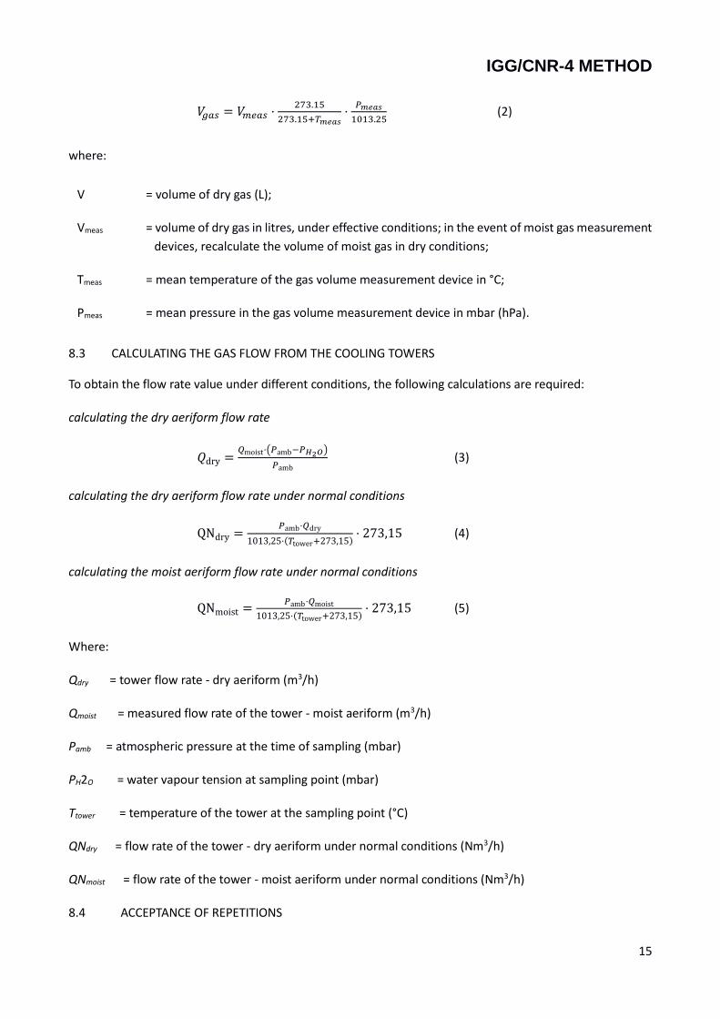
8.2 VOLUME OF GAS UNDER REFERENCE CONDITIONS
The volume of gas under reference conditions is calculated as follows:
IGG/CNR-4 METHOD
15
𝑉𝑔𝑎𝑠 = 𝑉𝑚𝑒𝑎𝑠 ⋅273.15
273.15+𝑇𝑚𝑒𝑎𝑠⋅𝑃𝑚𝑒𝑎𝑠
1013.25 (2)
where:
V = volume of dry gas (L);
Vmeas = volume of dry gas in litres, under effective conditions; in the event of moist gas measurement
devices, recalculate the volume of moist gas in dry conditions;
Tmeas = mean temperature of the gas volume measurement device in °C;
Pmeas = mean pressure in the gas volume measurement device in mbar (hPa).
8.3 CALCULATING THE GAS FLOW FROM THE COOLING TOWERS
To obtain the flow rate value under different conditions, the following calculations are required:
calculating the dry aeriform flow rate
𝑄dry =𝑄moist⋅(𝑃amb−𝑃𝐻2𝑂)
𝑃amb (3)
calculating the dry aeriform flow rate under normal conditions
QNdry =𝑃amb⋅𝑄dry
1013,25⋅(𝑇tower+273,15)⋅ 273,15 (4)
calculating the moist aeriform flow rate under normal conditions
QNmoist =𝑃amb⋅𝑄moist
1013,25⋅(𝑇tower+273,15)⋅ 273,15 (5)
Where:
Qdry = tower flow rate - dry aeriform (m3/h)
Qmoist = measured flow rate of the tower - moist aeriform (m3/h)
Pamb = atmospheric pressure at the time of sampling (mbar)
PH2O = water vapour tension at sampling point (mbar)
Ttower = temperature of the tower at the sampling point (°C)
QNdry = flow rate of the tower - dry aeriform under normal conditions (Nm3/h)
QNmoist = flow rate of the tower - moist aeriform under normal conditions (Nm3/h)
8.4 ACCEPTANCE OF REPETITIONS
IGG/CNR-4 METHOD
16
See appendix A
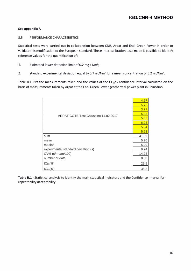
8.5 PERFORMANCE CHARACTERISTICS
Statistical tests were carried out in collaboration between CNR, Arpat and Enel Green Power in order to
validate this modification to the European standard. These inter-calibration tests made it possible to identify
reference values for the quantification of:
1. Estimated lower detection limit of 0.2 mg / Nm3;
2. standard experimental deviation equal to 0,7 ng/Nm3 for a mean concentration of 5.2 ng/Nm3. Table B.1 lists the measurements taken and the values of the CI 99% confidence interval calculated on the
basis of measurements taken by Arpat at the Enel Green Power geothermal power plant in Chiusdino.
ARPAT CGTE Test Chiusdino 14.02.2017
4.57
5.72
3.77
5.08
5.85
6.03
5.34
5.23
sum 41.59
mean 5.20
median 5.29
experimental standard deviation (s) 0.74
CV% (s/mean*100) 14.28
number of data 8.00
IC95(%) 23.9
IC99(%) 35.3
Table B.1 - Statistical analysis to identify the main statistical indicators and the Confidence Interval for repeatability acceptability.
IGG/CNR-4 METHOD
17
9. TEST REPORT
The test report must contain at least the following information:
1. reference to this method;
2. reference to the sampling report
3. identification and number of sample(s);
4. description of plant and process;
5. plant operating conditions;
6. position of sampling points;
7. number of sampling points and identification of the sampled cell;
8. sampling time;
9. sampling volume(s);
10. type of absorbers;
11. total Hydrogen Sulphide content as a mass concentration;
Certain information may be recorded in the sampling report referenced by the test report.
APPENDIX A: ACCEPTABLE OF REPLICATED DATA (THREE REPLICATIONS IN PARALLEL)
Once the acceptability of the single sample has been evaluated in accordance with the procedure highlighted
in paragraph 5.4 of this method, the most appropriate statistical method for the acceptance of the three
replicates and identification of outliers is based on the Confidence Interval (IC) 99% (assessed in advance on
at least 6 replicates) using the following formulas
𝐼𝐶99 = 𝑡99 ⋅𝑠
√𝑛 eq. 1
Where:
1. IC99 - 99% confidence interval calculated through at least 6 replications 2. t99 - Student t ( α 0.01; n. tests) 3. s - experimental standard deviation:
𝑠 = √∑ (𝑥𝑖−�̅�)
2𝑛1
𝑛−1 eq. 2
1. 𝑥𝑖 is the i-nth measurement 2. x̅ is the arithmetic mean of the measurements
IGG/CNR-4 METHOD
18
3. n. is the number of measurements performed 4. CI99% is given by the following formula:
𝐼𝐶99% =𝐼𝐶99
�̅�100 eq. 3
The results obtained from the three replications carried out in the sampling stage must be evaluated in
order to identify any outliers using the following condition:
|𝑥𝑖 − 𝑥𝑚𝑒𝑑𝑖𝑎𝑛| >𝐼𝐶99%
100∗ 𝑥𝑚𝑒𝑑𝑖𝑎𝑛 eq. 4
That may be transcribed as:
𝑥𝑚𝑒𝑑𝑖𝑎𝑛 −𝐼𝐶99%
100∗ 𝑥𝑚𝑒𝑑𝑖𝑎𝑛 < 𝑥𝑖 < 𝑥𝑚𝑒𝑑𝑖𝑎𝑛 +
𝐼𝐶99%
100∗ 𝑥𝑚𝑒𝑑𝑖𝑎𝑛 eq. 4 bis
Where:
𝑥𝑚𝑒𝑑𝑖𝑎𝑛 is the median of the three replications.
𝐶𝐼99% is defined in accordance with equation 3
𝑥𝑖 Is the i-nth reading
In accordance with the selection criteria for samples considered to acceptable as per the foregoing discussion
and section 5.4, the following cases may arise:
In the light of the data obtained, equation (4) becomes:
|𝑥𝑖 − 𝑥𝑚𝑒𝑑𝑖𝑎𝑛| < 0.559 ∗ 𝑥𝑚𝑒𝑑𝑖𝑎𝑛 = data acceptability condition
This is the acceptability condition for values found in the field.
Ed. Note :the median was considered rather than the mean because the median is a statistically more robust
parameter; moreover, if the mean had been used, a combination might have occurred whereby none of the
three samples would be acceptable, thereby invalidating the entire sampling process.
On the basis of the foregoing, the following cases may occur:
IGG/CNR-4 METHOD
19
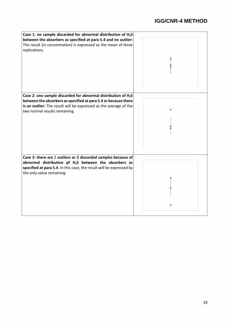
Case 1: no sample discarded for abnormal distribution of H2S between the absorbers as specified at para 5.4 and no outlier: The result (in concentration) is expressed as the mean of three replications.
Case 2: one sample discarded for abnormal distribution of H2S between the absorbers as specified at para 5.4 or because there is an outlier: The result will be expressed as the average of the two normal results remaining.
Case 3: there are 2 outliers or 2 discarded samples because of abnormal distribution pf H2S between the absorbers as specified at para 5.4. In this case, the result will be expressed by the only value remaining