Embed Size (px)
Citation preview
Copyright © 2017 Texas Instruments Incorporated. All rights reserved.
Information in this document is subject to change without notice. Texas Instruments may have pending patent applications, trademarks, copyrights, or other intellectual property rights covering matter in this document. The furnishing of this documents is given for usage with Texas Instruments products only and does not give you any license to the intellectual property that might be contained within this document. Texas Instruments makes no implied or expressed warranties in this document and is not responsible for the products based from this document.
SBL User Guide Page 1 of 38
SBL User Guide
SBL (Secondary Boot Loader)
User Guide
SBL User Guide Page 2 of 38
1 Table of Contents 1 Table of Contents .................................................................................................................................. 2
1. Introduction ........................................................................................................................................... 5
2 SBL Supported Devices .......................................................................................................................... 5
3 Image Formats ....................................................................................................................................... 6
SBL Bootloader Image ................................................................................................................... 6 3.1
CH Image ....................................................................................................................................... 7 3.2
Application Image .......................................................................................................................... 7 3.3
3.3.1 TDA3xx SBL ...................................................................................................................... 10
4 Building the SBL ................................................................................................................................... 11
5 Boot Modes of SBL .............................................................................................................................. 12
Flash Tools ................................................................................................................................... 13 5.1
5.1.1 QSPI Flash Writer ............................................................................................................... 13
5.1.2 NOR Flash Writer................................................................................................................ 13
QSPI boot mode........................................................................................................................... 13 5.2
NOR Boot Mode .......................................................................................................................... 14 5.3
MMCSD Boot Mode ..................................................................................................................... 15 5.4
5.4.1 Using PC tool........................................................................................................................ 15
5.4.2 Option 2: Steps to prepare a bootable SD card using DISKPART ........................................ 16
QSPI_SD Boot Mode .................................................................................................................... 17 5.5
6 Board Modification .............................................................................................................................. 18
TDA2xx Board Modification for NOR BOOT Mode: ..................................................................... 18 6.1
TDA2Px Board Modification for NOR BOOT Mode:..................................................................... 18 6.2
TDA2Ex Board Modification for NOR and QSPI BOOT Mode: ..................................................... 19 6.3
TDA2Ex_17x17 Board Modification for NOR BOOT Mode: ......................................................... 20 6.4
SBL User Guide Page 3 of 38
TDA3xx Board Modification for NOR BOOT Mode: ..................................................................... 21 6.5
7 Build Mode .......................................................................................................................................... 22
8 EMIFMODE .......................................................................................................................................... 22
9 Multi OPP Support ............................................................................................................................... 22
10 SBL Optimization Level .................................................................................................................... 24
11 PAD Configuration ........................................................................................................................... 24
12 WatchDog Timer2 (WD_TIMER2) .................................................................................................... 25
13 DSP Boot address alignment ........................................................................................................... 25
14 AD PLL Clock Frequency .................................................................................................................. 25
15 Boot-Up time ................................................................................................................................... 25
TDA2xx Device ............................................................................................................................. 25 15.1
15.1.1 QSPI Boot mode: ................................................................................................................. 25
15.1.2 NOR Boot mode: .................................................................................................................. 26
15.1.3 SD Boot mode: ..................................................................................................................... 26
TDA2Px Device ............................................................................................................................. 26 15.2
TDA2Ex Device ............................................................................................................................. 27 15.3
TDA2Ex_17x17 Device ................................................................................................................. 28 15.4
TDA3xx Device ............................................................................................................................. 29 15.5
16 Component Folder ........................................................................................................................... 30
17 UART Console .................................................................................................................................. 30
18 Prebuilt Binaries .............................................................................................................................. 32
19 Multi core Image generation script ................................................................................................. 32
20 SBL Multicore Mailbox app.............................................................................................................. 32
21 HS device support ............................................................................................................................ 33
Memory map ............................................................................................................................... 33 21.1
Boot authentication..................................................................................................................... 33 21.2
SBL User Guide Page 4 of 38
21.2.1 Setting up MShield-DK/SECDEV for TDA2x .......................................................................... 33
21.2.2 Boot-Image (PPA + SBL) generation .................................................................................... 36
21.2.3 Signing AppImages .............................................................................................................. 36
22 Flashing production binaries using – mflash ................................................................................... 37
22.1.1 PC side setup ....................................................................................................................... 37
22.1.2 Build steps ........................................................................................................................... 37
22.1.3 Generating mflash SBL......................................................................................................... 37
23 Known Issues ................................................................................................................................... 37
24 Revision History ............................................................................................................................... 38
SBL User Guide Page 5 of 38
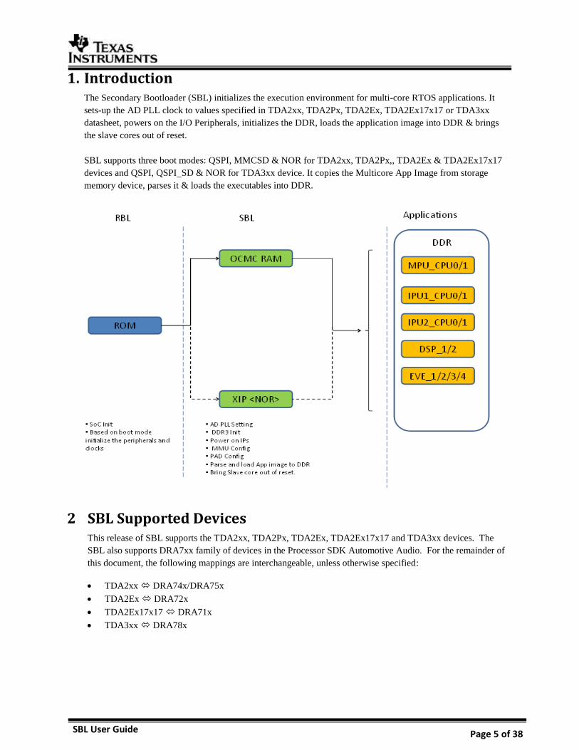
1. Introduction The Secondary Bootloader (SBL) initializes the execution environment for multi-core RTOS applications. It
sets-up the AD PLL clock to values specified in TDA2xx, TDA2Px, TDA2Ex, TDA2Ex17x17 or TDA3xx
datasheet, powers on the I/O Peripherals, initializes the DDR, loads the application image into DDR & brings
the slave cores out of reset.
SBL supports three boot modes: QSPI, MMCSD & NOR for TDA2xx, TDA2Px,, TDA2Ex & TDA2Ex17x17
devices and QSPI, QSPI_SD & NOR for TDA3xx device. It copies the Multicore App Image from storage
memory device, parses it & loads the executables into DDR.
2 SBL Supported Devices This release of SBL supports the TDA2xx, TDA2Px, TDA2Ex, TDA2Ex17x17 and TDA3xx devices. The
SBL also supports DRA7xx family of devices in the Processor SDK Automotive Audio. For the remainder of
this document, the following mappings are interchangeable, unless otherwise specified:
TDA2xx DRA74x/DRA75x
TDA2Ex DRA72x
TDA2Ex17x17 DRA71x
TDA3xx DRA78x
SBL User Guide Page 6 of 38
3 Image Formats SBL Image Format:
In non-XIP boot mode, RBL expects the GP header to execute SBL and in XIP boot mode, it expects the SBL
image in bin format. SBL image along with GP header is referred as tiimage. For more information on tiimage,
refer to the section 3.1 of this user guide.
Application Image Format:
AppImage generation is two-step process: RPRC format conversion & Multicore Image file generation.
i) Firstly, application executable has to be converted from ELF/COFF format to custom TI RPRC image
format. For more information on RPRC format, refer to the section 3.3.1 of this user guide.
ii) AppImage is a Multicore image file that includes the RPRC image file of individual cores. It contains
the CPU ID & boot-up sequence. For more information on Multicore Image format, refer to the section
3.3.2 of this user guide.
SBL Bootloader Image 3.1
The Boot loader Image should be converted as given in this section:
1. Convert the ELF image to binary.
SBL should be changed into binary format using the following command:
$ arm-none-eabi-objcopy.exe --gap-fill=0xff -O binary SBL.out SBL.bin
arm-none-eabi-objcopy.exe is part of Linaro or Code-sourcery tool chain and is not provided as part of the PDK
package.
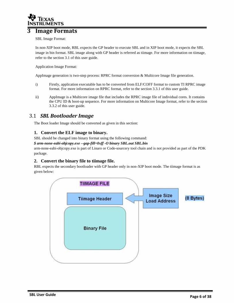
2. Convert the binary file to tiimage file.
RBL expects the secondary bootloader with GP header only in non-XIP boot mode. The tiimage format is as
given below:
SBL User Guide Page 7 of 38
Using following command convert the generated bin file to tiimage:
$tiimage.exe <Load Address> <ENDIAN> SBL.bin SBL.tiimage
SBL sections should be mapped to OCMC region using the linker command file while building the SBL.
Load Address for SBL is 0x40300000 for TDA2xx/TDA2Px/TDA2Ex/ TDA2Ex17x17 whereas on TDA3xx
this address is 0x00300000 as RBL already configures AMMU mapping of medium pages.
ENDIAN (BE/LE) specifies whether the TI header and the binary is in Big Endian/Little Endian.
For SPI/QSPI boot mode, the RBL expects the SBL in Big Endian.
For other boot modes (SD), the RBL expects the SBL in Little Endian.
tiimage.exe is provided as part of the PDK package under the folder packages/ti/boot/sbl_auto/tools/tiimage.
CH Image 3.2
For fast boot on TDA3xx platform in QSPI and QSPI_SD boot mode, RBL can also boot another type of image
called chimage (Configuration Header Image). RBL sets up QSPI speed as 48 MHz by default. On adding the
CH header to tiimage we can change the QSPI speed. The configuration header is prepended to tiimage to create
chimage. The size of header is 0x200 bytes.
Boot loader Image should be converted to chimage using below command:
$chimage.exe CH.bin SBL.tiimage SBL.chimage
Chimage.exe tool and the CH bin for TDA3xx (tda3x_chqspi_clock64mhz.bin) are present in folder
packages/ti/boot/sbl_auto/tools/chimage.
Application Image 3.3
The Application Image should be converted as given in this section. The Application Images of all the Cores
should be built in ELF/Coff format and converted to a single file called Multi core Image file.
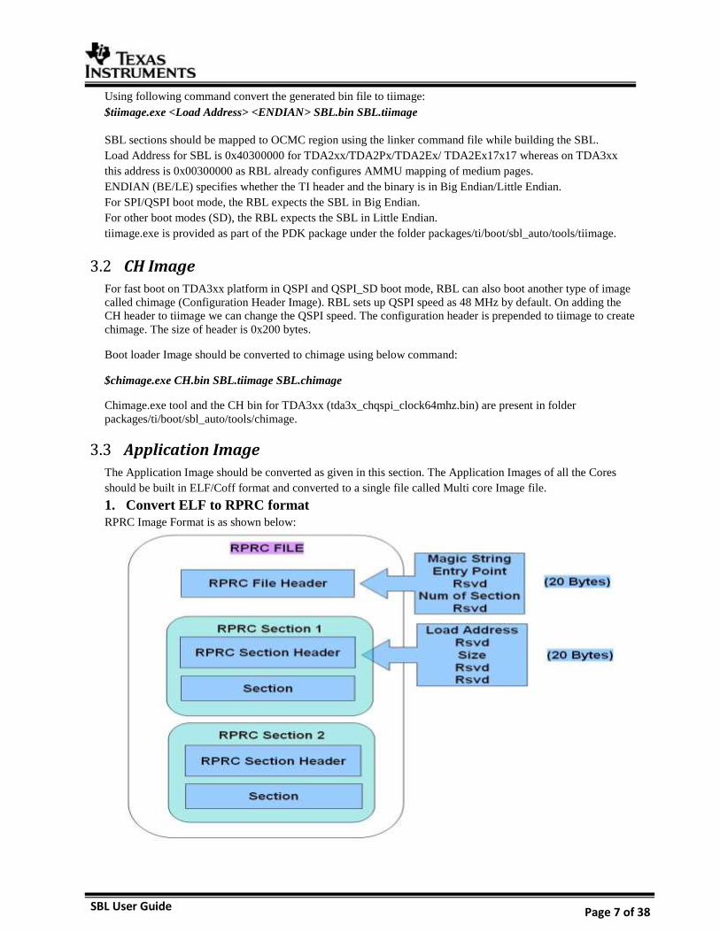
1. Convert ELF to RPRC format
RPRC Image Format is as shown below:
SBL User Guide Page 8 of 38
As shown in above diagram, RPRC file has one file header and multiple sections. File Header contains Magic
string for sanity check of the image, Entry Point, Number of Sections and One reserved word.
File header is followed by multiple Sections. Each Section has section header and section data. The Section
Header has five words: Load address, one reserved word, size and two reserved words. Address specifies the
destination address of that section and size specifies section size in bytes of the Section Data that follows. The
whole section has to be copied to the load address. RPRC sections are generated for each elf section as part of
the elf executable.
Convert the different application image files (ELF/COFF) for various cores to RPRC image using the following
command:
$out2rprc.exe <App_In_name(elf or coff)> <App_out_name>
out2rprc.exe is provided in tools as part of the PDK package under packages/ti/boot/sbl_auto/tools/out2rprc.
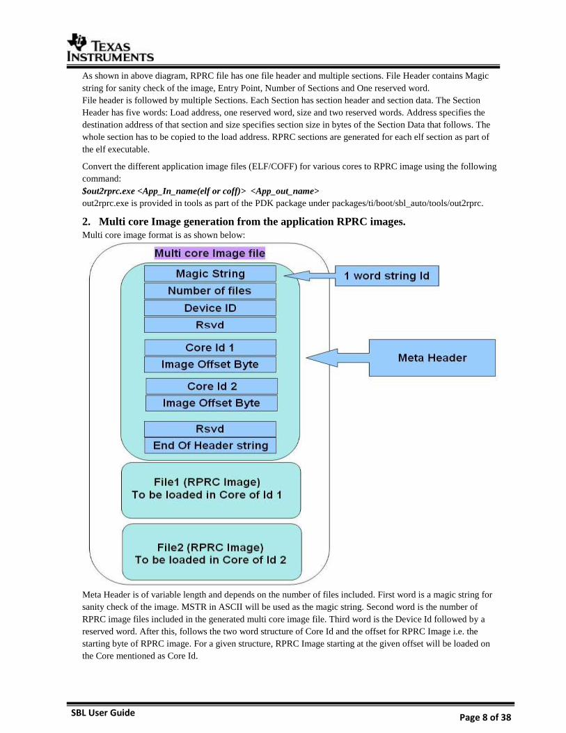
2. Multi core Image generation from the application RPRC images.
Multi core image format is as shown below:
Meta Header is of variable length and depends on the number of files included. First word is a magic string for
sanity check of the image. MSTR in ASCII will be used as the magic string. Second word is the number of
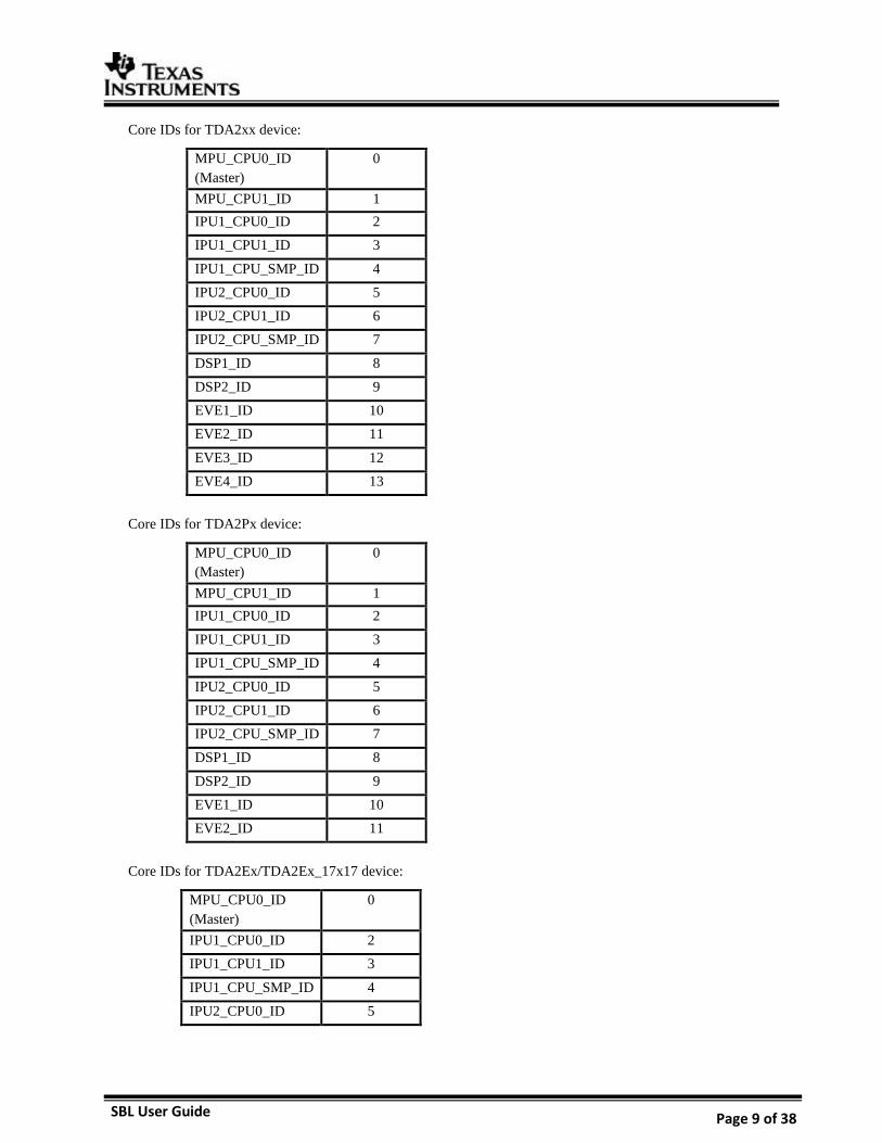
RPRC image files included in the generated multi core image file. Third word is the Device Id followed by a
reserved word. After this, follows the two word structure of Core Id and the offset for RPRC Image i.e. the
starting byte of RPRC image. For a given structure, RPRC Image starting at the given offset will be loaded on
the Core mentioned as Core Id.
SBL User Guide Page 9 of 38
Core IDs for TDA2xx device:
MPU_CPU0_ID
(Master)
0
MPU_CPU1_ID 1
IPU1_CPU0_ID 2
IPU1_CPU1_ID 3
IPU1_CPU_SMP_ID 4
IPU2_CPU0_ID 5
IPU2_CPU1_ID 6
IPU2_CPU_SMP_ID 7
DSP1_ID 8
DSP2_ID 9
EVE1_ID 10
EVE2_ID 11
EVE3_ID 12
EVE4_ID 13
Core IDs for TDA2Px device:
MPU_CPU0_ID
(Master)
0
MPU_CPU1_ID 1
IPU1_CPU0_ID 2
IPU1_CPU1_ID 3
IPU1_CPU_SMP_ID 4
IPU2_CPU0_ID 5
IPU2_CPU1_ID 6
IPU2_CPU_SMP_ID 7
DSP1_ID 8
DSP2_ID 9
EVE1_ID 10
EVE2_ID 11
Core IDs for TDA2Ex/TDA2Ex_17x17 device:
MPU_CPU0_ID
(Master)
0
IPU1_CPU0_ID 2
IPU1_CPU1_ID 3
IPU1_CPU_SMP_ID 4
IPU2_CPU0_ID 5
SBL User Guide Page 10 of 38
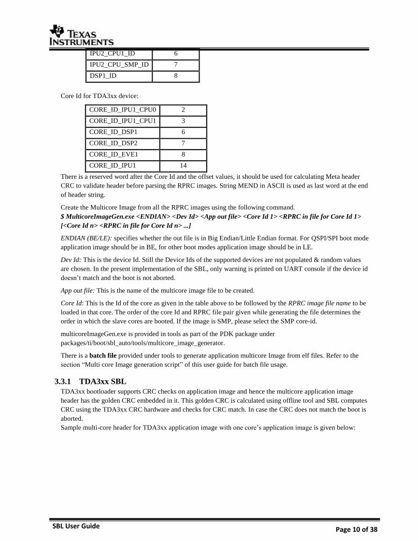
IPU2_CPU1_ID 6
IPU2_CPU_SMP_ID 7
DSP1_ID 8
Core Id for TDA3xx device:
CORE_ID_IPU1_CPU0 2
CORE_ID_IPU1_CPU1 3
CORE_ID_DSP1 6
CORE_ID_DSP2 7
CORE_ID_EVE1 8
CORE_ID_IPU1 14
There is a reserved word after the Core Id and the offset values, it should be used for calculating Meta header
CRC to validate header before parsing the RPRC images. String MEND in ASCII is used as last word at the end
of header string.
Create the Multicore Image from all the RPRC images using the following command.
$ MulticoreImageGen.exe <ENDIAN> <Dev Id> <App out file> <Core Id 1> <RPRC in file for Core Id 1>
[<Core Id n> <RPRC in file for Core Id n> ...]
ENDIAN (BE/LE): specifies whether the out file is in Big Endian/Little Endian format. For QSPI/SPI boot mode
application image should be in BE, for other boot modes application image should be in LE.
Dev Id: This is the device Id. Still the Device Ids of the supported devices are not populated & random values
are chosen. In the present implementation of the SBL, only warning is printed on UART console if the device id
doesn’t match and the boot is not aborted.
App out file: This is the name of the multicore image file to be created.
Core Id: This is the Id of the core as given in the table above to be followed by the RPRC image file name to be
loaded in that core. The order of the core Id and RPRC file pair given while generating the file determines the
order in which the slave cores are booted. If the image is SMP, please select the SMP core-id.
multicoreImageGen.exe is provided in tools as part of the PDK package under
packages/ti/boot/sbl_auto/tools/multicore_image_generator.
There is a batch file provided under tools to generate application multicore Image from elf files. Refer to the
section “Multi core Image generation script” of this user guide for batch file usage.
3.3.1 TDA3xx SBL
TDA3xx bootloader supports CRC checks on application image and hence the multicore application image
header has the golden CRC embedded in it. This golden CRC is calculated using offline tool and SBL computes
CRC using the TDA3xx CRC hardware and checks for CRC match. In case the CRC does not match the boot is
aborted.
Sample multi-core header for TDA3xx application image with one core’s application image is given below:
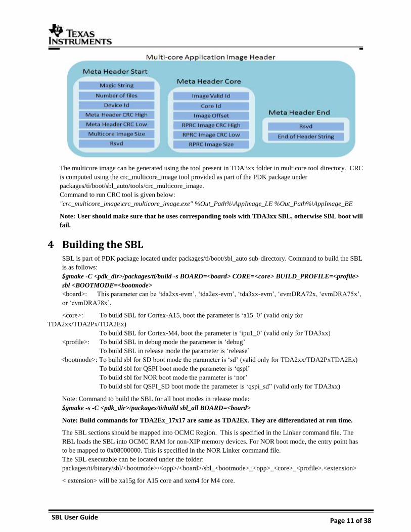
SBL User Guide Page 11 of 38
The multicore image can be generated using the tool present in TDA3xx folder in multicore tool directory. CRC
is computed using the crc_multicore_image tool provided as part of the PDK package under
packages/ti/boot/sbl_auto/tools/crc_multicore_image.
Command to run CRC tool is given below:
"crc_multicore_image\crc_multicore_image.exe" %Out_Path%\AppImage_LE %Out_Path%\AppImage_BE
Note: User should make sure that he uses corresponding tools with TDA3xx SBL, otherwise SBL boot will
fail.
4 Building the SBL SBL is part of PDK package located under packages/ti/boot/sbl_auto sub-directory. Command to build the SBL
is as follows:
$gmake -C <pdk_dir>/packages/ti/build -s BOARD=<board> CORE=<core> BUILD_PROFILE=<profile>
sbl <BOOTMODE=<bootmode>
<board>: This parameter can be ‘tda2xx-evm’, ‘tda2ex-evm’, ‘tda3xx-evm’, ‘evmDRA72x, ‘evmDRA75x’,
or ‘evmDRA78x’.
<core>: To build SBL for Cortex-A15, boot the parameter is ‘a15_0’ (valid only for
TDA2xx/TDA2Px/TDA2Ex)
To build SBL for Cortex-M4, boot the parameter is ‘ipu1_0’ (valid only for TDA3xx)
<profile>: To build SBL in debug mode the parameter is ‘debug’
To build SBL in release mode the parameter is ‘release’
<bootmode>: To build sbl for SD boot mode the parameter is ‘sd’ (valid only for TDA2xx/TDA2PxTDA2Ex)
To build sbl for QSPI boot mode the parameter is ‘qspi’
To build sbl for NOR boot mode the parameter is ‘nor’
To build sbl for QSPI_SD boot mode the parameter is ‘qspi_sd” (valid only for TDA3xx)
Note: Command to build the SBL for all boot modes in release mode:
$gmake -s -C <pdk_dir>/packages/ti/build sbl_all BOARD=<board>
Note: Build commands for TDA2Ex_17x17 are same as TDA2Ex. They are differentiated at run time.
The SBL sections should be mapped into OCMC Region. This is specified in the Linker command file. The
RBL loads the SBL into OCMC RAM for non-XIP memory devices. For NOR boot mode, the entry point has
to be mapped to 0x08000000. This is specified in the NOR Linker command file.
The SBL executable can be located under the folder:
packages/ti/binary/sbl/<bootmode>/<opp>/<board>/sbl_<bootmode>_<opp>_<core>_<profile>.<extension>
< extension> will be xa15g for A15 core and xem4 for M4 core.
SBL User Guide Page 12 of 38
To convert the elf image into bin & tiimage file refer to the section 3.1 “SBL Bootloader Image” of this user
guide.
5 Boot Modes of SBL Supported boot modes on TDA2xx ES1.1 and ES2.0 device:
Boot Mode EVM Switch SYSBOOT(SW2)[1:16] EVM Switch SW5[1:10]
Execution
Mode Entry location
QSPI_1 01101100 10000001 1110100000 Non-XIP 0x40300000
QSPI_4 11101100 10000001 1110100000 Non-XIP 0x40300000
NOR 10101100 10000101 0100100000 XIP 0x08000000
SD 00001100 10000001 0001100000 Non-XIP 0x40300000
Debug 00000000 10000001 XXXXXXXX
Supported boot modes on TDA2xx ES1.0 device:
Boot Mode EVM Switch SYSBOOT(SW2)[1:16] EVM Switch SW5[1:10]
Execution
Mode Entry location
QSPI 01101100 10000001 1110100000 Non-XIP 0x40300000
NOR 10101100 10000101 0100100000 XIP 0x08000000
SD 11100000 10000001 0001100000 Non-XIP 0x40300000
Supported boot modes on TDA2Px/TDA2Ex/TDA2Ex_17x17 ES1.0 device:
Boot Mode EVM Switch SYSBOOT(SW2)[1:16] EVM Switch SW5[1:10]
Execution
Mode Entry location
QSPI_1 01101100 10000001 0001100000 Non-XIP 0x40300000
QSPI_4 11101100 10000001 0001100000 Non-XIP 0x40300000
NOR 10101100 10000101 0100100000 XIP 0x08000000
SD 00001100 10000001 0001100000 Non-XIP 0x40300000
Debug 00000000 10000001 XXXXXXXX
Supported boot modes on TDA3xx 15X15 ES1.0 and ES2.0 device:
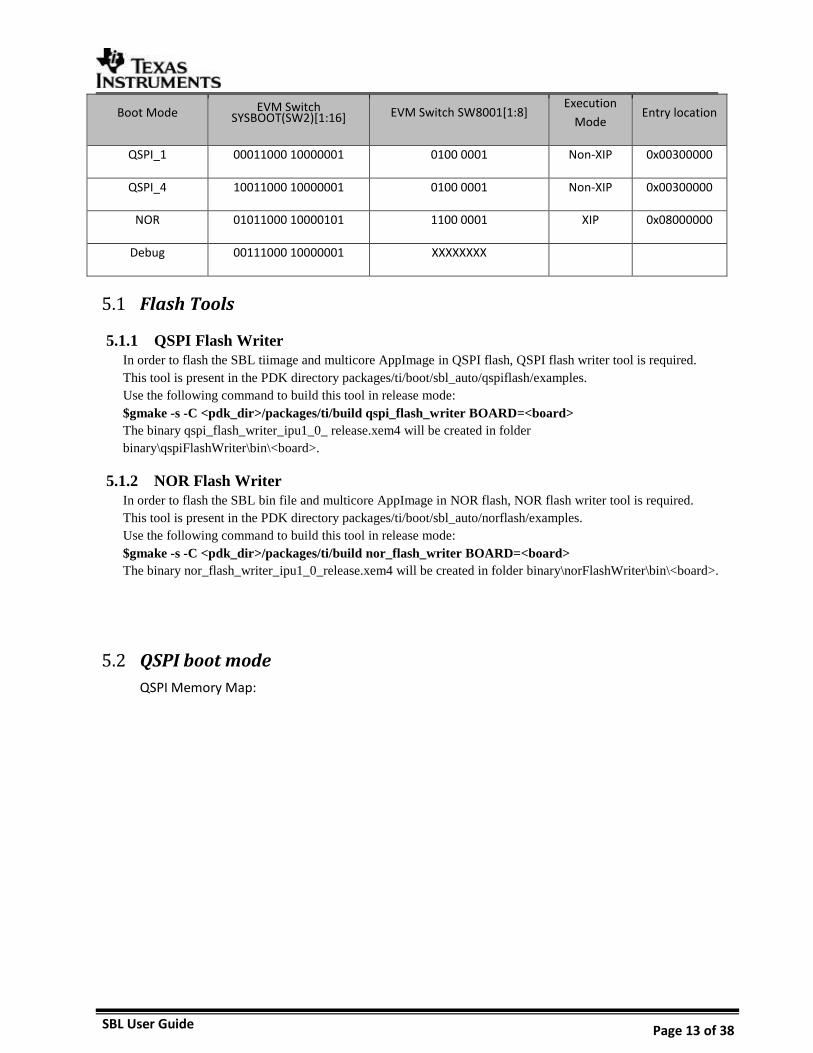
SBL User Guide Page 13 of 38
Boot Mode EVM Switch SYSBOOT(SW2)[1:16] EVM Switch SW8001[1:8]
Execution
Mode Entry location
QSPI_1 00011000 10000001 0100 0001 Non-XIP 0x00300000
QSPI_4 10011000 10000001 0100 0001 Non-XIP 0x00300000
NOR 01011000 10000101 1100 0001 XIP 0x08000000
Debug 00111000 10000001 XXXXXXXX
Flash Tools 5.1
5.1.1 QSPI Flash Writer
In order to flash the SBL tiimage and multicore AppImage in QSPI flash, QSPI flash writer tool is required.
This tool is present in the PDK directory packages/ti/boot/sbl_auto/qspiflash/examples.
Use the following command to build this tool in release mode:
$gmake -s -C <pdk_dir>/packages/ti/build qspi_flash_writer BOARD=<board>
The binary qspi_flash_writer_ipu1_0_ release.xem4 will be created in folder
binary\qspiFlashWriter\bin\<board>.
5.1.2 NOR Flash Writer
In order to flash the SBL bin file and multicore AppImage in NOR flash, NOR flash writer tool is required.
This tool is present in the PDK directory packages/ti/boot/sbl_auto/norflash/examples.
Use the following command to build this tool in release mode:
$gmake -s -C <pdk_dir>/packages/ti/build nor_flash_writer BOARD=<board>
The binary nor_flash_writer_ipu1_0_release.xem4 will be created in folder binary\norFlashWriter\bin\<board>.
QSPI boot mode 5.2
QSPI Memory Map:
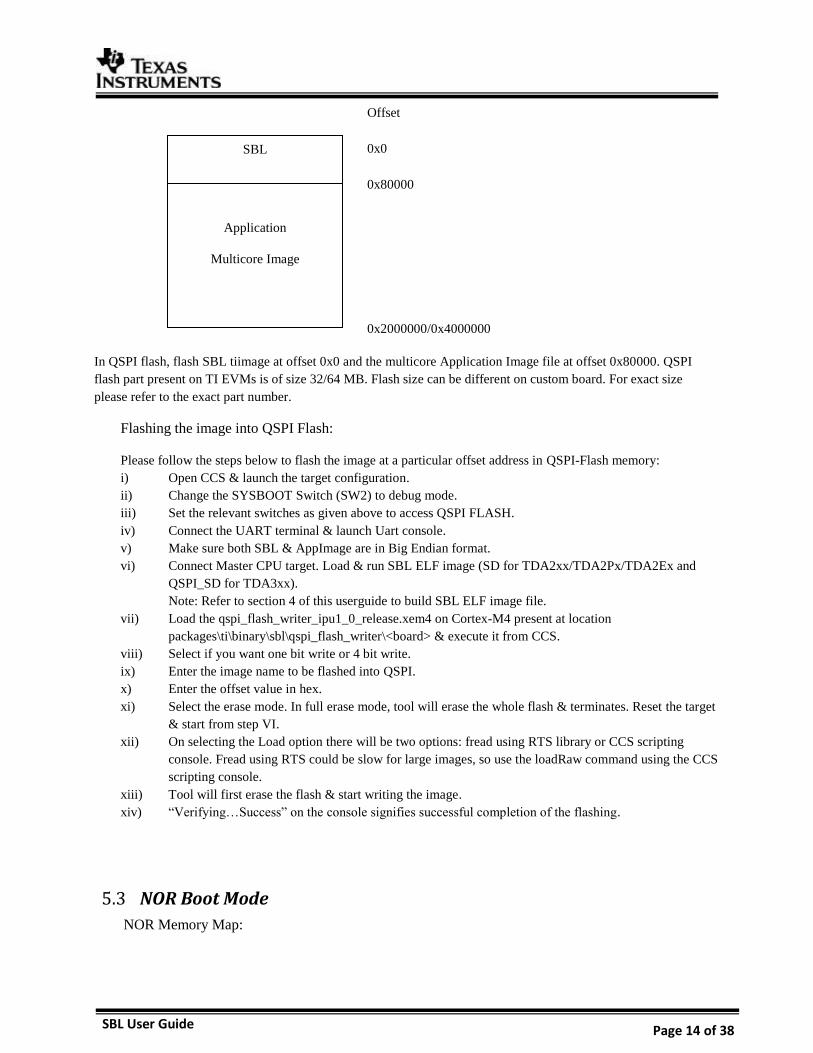
SBL User Guide Page 14 of 38
In QSPI flash, flash SBL tiimage at offset 0x0 and the multicore Application Image file at offset 0x80000. QSPI
flash part present on TI EVMs is of size 32/64 MB. Flash size can be different on custom board. For exact size
please refer to the exact part number.
Flashing the image into QSPI Flash:
Please follow the steps below to flash the image at a particular offset address in QSPI-Flash memory:
i) Open CCS & launch the target configuration.
ii) Change the SYSBOOT Switch (SW2) to debug mode.
iii) Set the relevant switches as given above to access QSPI FLASH.
iv) Connect the UART terminal & launch Uart console.
v) Make sure both SBL & AppImage are in Big Endian format.
vi) Connect Master CPU target. Load & run SBL ELF image (SD for TDA2xx/TDA2Px/TDA2Ex and
QSPI_SD for TDA3xx).
Note: Refer to section 4 of this userguide to build SBL ELF image file.
vii) Load the qspi_flash_writer_ipu1_0_release.xem4 on Cortex-M4 present at location
packages\ti\binary\sbl\qspi_flash_writer\<board> & execute it from CCS.
viii) Select if you want one bit write or 4 bit write.
ix) Enter the image name to be flashed into QSPI.
x) Enter the offset value in hex.
xi) Select the erase mode. In full erase mode, tool will erase the whole flash & terminates. Reset the target
& start from step VI.
xii) On selecting the Load option there will be two options: fread using RTS library or CCS scripting
console. Fread using RTS could be slow for large images, so use the loadRaw command using the CCS
scripting console.
xiii) Tool will first erase the flash & start writing the image.
xiv) “Verifying…Success” on the console signifies successful completion of the flashing.
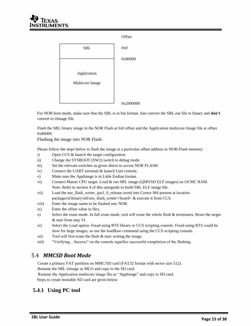
NOR Boot Mode 5.3
NOR Memory Map:
SBL
Application
Multicore Image
Offset
0x0
0x80000
0x2000000/0x4000000
SBL User Guide Page 15 of 38
For NOR boot mode, make sure that the SBL is in bin format. Just convert the SBL.out file to binary and don’t
convert to tiimage file.
Flash the SBL binary image in the NOR Flash at 0x0 offset and the Application multicore Image file at offset
0x80000.
Flashing the image into NOR Flash:
Please follow the steps below to flash the image at a particular offset address in NOR-Flash memory:
i) Open CCS & launch the target configuration.
ii) Change the SYSBOOT (SW2) switch to debug mode.
iii) Set the relevant switches as given above to access NOR FLASH.
iv) Connect the UART terminal & launch Uart console.
v) Make sure the AppImage is in Little Endian format.
vi) Connect Master CPU target. Load & run SBL image (QSPI/SD ELF images) on OCMC RAM.
Note: Refer to section 4 of this userguide to build SBL ELF image file.
vii) Load the nor_flash_writer_ipu1_0_release.xem4 into Cortex-M4 present at location
packages\ti\binary\sbl\nor_flash_writer\<board> & execute it from CCS.
viii) Enter the image name to be flashed into NOR.
ix) Enter the offset value in Hex.
x) Select the erase mode. In full erase mode, tool will erase the whole flash & terminates. Reset the target
& start from step VI.
xi) Select the Load option. Fread using RTS library or CCS scripting console. Fread using RTS could be
slow for large images, so use the loadRaw command using the CCS scripting console.
xii) Tool will first erase the flash & start writing the image.
xiii) “Verifying…Success” on the console signifies successful completion of the flashing.
MMCSD Boot Mode 5.4
Create a primary FAT partition on MMC/SD card (FAT32 format with sector size 512).
Rename the SBL tiimage as MLO and copy to the SD card.
Rename the Application multicore image file as “AppImage” and copy to SD card.
Steps to create bootable SD card are given below
5.4.1 Using PC tool
SBL
Application
Multicore Image
Offset
0x0
0x80000
0x2000000
SBL User Guide Page 16 of 38
Ensure Empty SD card (at least 256MB, preferably 4GB SDHC) is available.
Ensure SD memory card reader is available.
Create a primary FAT partition on MMC/SD card (FAT32 format with sector size 512) and mark it as
Active. A partition manager utility has to be used for the same.
Format SD card from DOS command line as below.
“format <drive> /A:512 /FS:FAT32”
Make SD card partition as active using below tool:
http://www.pcdisk.com/download.html
IMPORTANT NOTE: Create a primary FAT partition on MMC/SD card (FAT32 format with sector size
512 bytes mark the partition as active.
5.4.2 Option 2: Steps to prepare a bootable SD card using DISKPART Open windows 7 Command prompt and Run as Administrator mode
Enter command "diskpart.exe"
C:\Windows\system32>diskpart.exe will take you DISKPART prompt
Warning: Enter below command carefully w.r.t your computer/laptop SD card disk number.
Choosing wrong disk number may delete data present in other drive
To list all disk drive present on computer:
DISKPART> list disk
Select the SD card disk number, in my case it is disk 1:
DISKPART> select disk 1
Now all next command applicable only to disk 1(SD card)
Delete entire partition:
DISKPART> clean
To create Primary partition:
DISKPART> create partition primary
To list partition:
DISKPART> list partition
Select partition:
DISKPART> select partition 1
To list volume:
DISKPART> list volume
Select volume associated with SD card, in our case it is 3:
DISKPART> select volume 3
Format SD card, please wait this may take few seconds:
DISKPART>format quick fs=fat32 unit=512 label=SD_BOOT
Make disk active:
DISKPART> active
To exit utility:
DISKPART> exit
SBL User Guide Page 17 of 38
QSPI_SD Boot Mode 5.5
In this boot mode, SBL is flashed on QSPI flash and AppImage is present on SD card.
Steps for how to flash the SBL on QSPI memory are present in section 5.2 of this userguide.
Create a primary FAT partition on MMC/SD card (FAT32 format with sector size 512).
Rename the Application multicore image file as “AppImage” and copy to SD card.
Note: Windows format disk not makes the SD card as bootable. Please format the card as bootable on Linux
based PC.
NOTE: Only SBL image should be flashed on QSPI.
SBL User Guide Page 18 of 38
6 Board Modification
TDA2xx Board Modification for NOR BOOT Mode: 6.1
By default QSPI’s Zero ohm resistor are connected and GPMC lines are opened. To get NOR working,
required to remove the QSPI Zero Ohm resistor & pop-up GPMC resistors as stated below.
Remove the R735 resistor and popup at R736 resistor => C_GPMC_A13
Remove the R737 resistor and popup at R738 resistor => C_GPMC_A14
Remove the R739 resistor and popup at R740 resistor => C_GPMC_A15
Remove the R741 resistor and popup at R742 resistor => C_GPMC_A16
Remove the R743 resistor and popup at R744 resistor => C_GPMC_A17
Remove the R745 resistor and popup at R746 resistor => C_GPMC_A18
Remove the R747 resistor and popup at R748 resistor => C_GPMC_nCS2
QSPI will not work on Tda2xx Board which is modified for NOR BOOT Mode. For NOR, EVM switch
setting SW5[1:10] – 0100100000
TDA2Px Board Modification for NOR BOOT Mode: 6.2
By default QSPI’s Zero ohm resistor are connected and GPMC lines are opened. To get NOR working,
required to remove the QSPI Zero Ohm resistor & pop-up GPMC resistors as stated below.
SBL User Guide Page 19 of 38
Remove the R173 resistor and popup at R172 resistor => C_GPMC_A13
Remove the R187 resistor and popup at R186 resistor => C_GPMC_A14
Remove the R181 resistor and popup at R180 resistor => C_GPMC_A15
Remove the R170 resistor and popup at R169 resistor => C_GPMC_A16
Remove the R175 resistor and popup at R174 resistor => C_GPMC_A17
Remove the R185 resistor and popup at R184 resistor => C_GPMC_A18
QSPI will not work on Tda2Px Board which is modified for NOR BOOT Mode. For NOR, EVM switch
setting SW5[1:10] – 0100100000
TDA2Ex Board Modification for NOR and QSPI BOOT Mode: 6.3
By default QSPI’s Zero ohm resistor are connected and GPMC lines are opened. To get NOR working,
required to remove the QSPI Zero Ohm resistor & pop-up GPMC resistors as stated below.
Remove the R735 resistor and popup at R736 resistor => C_GPMC_A13
Remove the R737 resistor and popup at R738 resistor => C_GPMC_A14
SBL User Guide Page 20 of 38
Remove the R739 resistor and popup at R740 resistor => C_GPMC_A15
Remove the R741 resistor and popup at R742 resistor => C_GPMC_A16
Remove the R743 resistor and popup at R744 resistor => C_GPMC_A17
Remove the R745 resistor and popup at R746 resistor => C_GPMC_A18
Remove the R747 resistor and popup at R748 resistor => C_GPMC_nCS2
For NOR, EVM switch setting SW5[1:10] – 0100100000. For SPI Flash, by default A-QSPI path resistor
are connected and B-QSPI path resistor are opened. To get QSPI working on the TDA2EX Board which is
modified for NOR, required to remove the A-QSPI path resistor & pop-up B-QSPI path resistor as stated
below.
Remove the R728 resistor and popup at R468 resistor => B_QSPI1_SCLK, QSPI1_RTCLK
Remove the R731 resistor and popup at R732 resistor => QSPI1_CS[0]
Remove the R729 resistor and popup at R444 resistor => QSPI1_D[0]
Remove the R730 resistor and popup at R132 resistor => QSPI1_D[1]
Remove the R733 resistor and popup at R443 resistor => QSPI1_D[2]
Remove the R726 resistor and popup at R130 resistor => QSPI1_D[3]
For QSPI, EVM switch setting SW5[1:10] – 0001100000
TDA2Ex_17x17 Board Modification for NOR BOOT Mode: 6.4
By default QSPI’s Zero ohm resistor are connected and GPMC lines are opened. To get NOR working,
required to remove the QSPI Zero Ohm resistor & pop-up GPMC resistors as stated below.
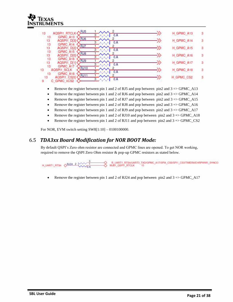
SBL User Guide Page 21 of 38
Remove the register between pin 1 and 2 of RJ5 and pop between pin2 and 3 => GPMC_A13
Remove the register between pin 1 and 2 of RJ6 and pop between pin2 and 3 => GPMC_A14
Remove the register between pin 1 and 2 of RJ7 and pop between pin2 and 3 => GPMC_A15
Remove the register between pin 1 and 2 of RJ8 and pop between pin2 and 3 => GPMC_A16
Remove the register between pin 1 and 2 of RJ9 and pop between pin2 and 3 => GPMC_A17
Remove the register between pin 1 and 2 of RJ10 and pop between pin2 and 3 => GPMC_A18
Remove the register between pin 1 and 2 of RJ11 and pop between pin2 and 3 => GPMC_CS2
For NOR, EVM switch setting SW8[1:10] – 0100100000.
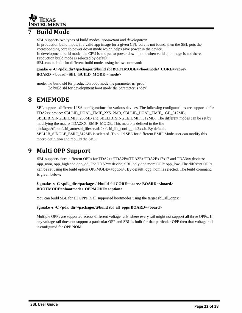
TDA3xx Board Modification for NOR BOOT Mode: 6.5
By default QSPI’s Zero ohm resistor are connected and GPMC lines are opened. To get NOR working,
required to remove the QSPI Zero Ohm resistor & pop-up GPMC resistors as stated below.
Remove the register between pin 1 and 2 of RJ24 and pop between pin2 and 3 => GPMC_A17
SBL User Guide Page 22 of 38
7 Build Mode SBL supports two types of build modes: production and development.
In production build mode, if a valid app image for a given CPU core is not found, then the SBL puts the
corresponding core to power down mode which helps save power in the device.
In development build mode, the CPU is not put to power down mode when valid app image is not there.
Production build mode is selected by default.
SBL can be built for different build modes using below command:
gmake -s -C <pdk_dir>/packages/ti/build sbl BOOTMODE=<bootmode> CORE=<core>
BOARD=<board> SBL_BUILD_MODE=<mode>
mode: To build sbl for production boot mode the parameter is ‘prod’
To build sbl for development boot mode the parameter is ‘dev’
8 EMIFMODE SBL supports different LISA configurations for various devices. The following configurations are supported for
TDA2xx device: SBLLIB_DUAL_EMIF_2X512MB, SBLLIB_DUAL_EMIF_1GB_512MB,
SBLLIB_SINGLE_EMIF_256MB and SBLLIB_SINGLE_EMIF_512MB. The different modes can be set by
modifying the macro TDA2XX_EMIF_MODE. This macro is defined in the file
packages\ti\boot\sbl_auto\sbl_lib\src\tda2xx\sbl_lib_config_tda2xx.h. By default,
SBLLIB_SINGLE_EMIF_512MB is selected. To build SBL for different EMIF Mode user can modify this
macro definition and rebuild the SBL.
9 Multi OPP Support SBL supports three different OPPs for TDA2xx/TDA2Px/TDA2Ex/TDA2Ex17x17 and TDA3xx devices:
opp_nom, opp_high and opp_od. For TDA2xx device, SBL only one more OPP: opp_low. The different OPPs
can be set using the build option OPPMODE=<option>. By default, opp_nom is selected. The build command
is given below:
$ gmake -s -C <pdk_dir>/packages/ti/build sbl CORE=<core> BOARD=<board>
BOOTMODE=<bootmode> OPPMODE=<option>
You can build SBL for all OPPs in all supported bootmodes using the target sbl_all_opps:
$gmake -s -C <pdk_dir>/packages/ti/build sbl_all_opps BOARD=<board>
Multiple OPPs are supported across different voltage rails where every rail might not support all three OPPs. If
any voltage rail does not support a particular OPP and SBL is built for that particular OPP then that voltage rail
is configured for OPP NOM.
SBL User Guide Page 23 of 38
Voltage Rail TDA2Px OPP Support
OPP LOW OPP NOM OPP OD OPP HIGH
VD_MPU Supported Supported Supported Supported
VD_DSPEVE Not Supported Supported Supported Supported
VD_IVA Not Supported Supported Supported Supported
VD_GPU Not Supported Supported Supported Supported
VD_CORE Not Supported Supported Not Supported Not Supported
Voltage Rail
TDA2Ex OPP SUPPORT
OPP NOM OPP OD OPP HIGH
VD_MPU Supported Supported Supported
VD_DSPEVE Supported Supported Supported
VD_IVA Supported Supported Supported
VD_GPU Supported Supported Supported
VD_CORE Supported Not Supported Not Supported
Voltage Rail
TDA2xx OPP SUPPORT
OPP LOW OPP NOM OPP OD OPP HIGH
VD_MPU Supported Supported Supported Supported
VD_DSPEVE Not Supported Supported Supported Supported
VD_IVA Not Supported Supported Supported Supported
VD_GPU Not Supported Supported Supported Supported
VD_CORE Not Supported Supported Not Supported Not Supported
SBL User Guide Page 24 of 38
Voltage Rail
TDA2Ex_17x17 OPP SUPPORT
OPP NOM OPP OD OPP HIGH
VD_MPU (Ganged
with VD Core on
EVM) Supported Not Supported Not Supported
VD_DSPEVE Supported Not Supported Supported
VD_IVA (Ganged
with VD DSP on EVM) Supported Not Supported Supported
VD_GPU (Ganged
with VD Core on
EVM) Supported Not Supported Not Supported
VD_CORE Supported Not Supported Not Supported
10 SBL Optimization Level SBL supports different levels of optimization in order to achieve better performance. This feature needs
platform specific modifications. There are three levels of optimization: ‘high’, ‘medium’ and ‘low’. The
amount of prints given by SBL reduces as the optimization level increases. By default the optimization level is
set as ‘low’. You can specify optimization level by using below build command:
gmake -s sbl BOOTMODE=<bootmode> BOARD=<board> SBL_OPT_MODE=<mode>
mode: To build sbl for high optimization level, the parameter is ‘high’
To build sbl for medium optimization level, the parameter is ‘medium’
To build sbl for low optimization level, the parameter is ‘low’
11 PAD Configuration PADs should be configured in isolation in case of TDA2xx, TDA2Ex and TDA2Ex17x17 device. This is done
when SBL configures IO delay. Currently the SBL is doing IO delay calibration for a sample use case. User has
to modify the pin mux configuration as per their use case. User needs to refer to device data sheet for adding IO
delay configuration. User can refer to IO Delay Configuration application note for more information on IO
Voltage Rail
TDA3xx OPP SUPPORT
OPP NOM OPP OD OPP HIGH
VD_DSPEVE Supported Supported Supported
VD_CORE Supported Not Supported Not Supported
SBL User Guide Page 25 of 38
recalibration and IO delay configuration (Link:
https://cdds.ext.ti.com/ematrix/common/emxNavigator.jsp?objectId=28670.42872.36762.42390).
12 WatchDog Timer2 (WD_TIMER2) For TDA2xx/TDA2Ex/TDA2Ex17x17 device, ROM Bootloader enables the WD_TIMER2 & sets the value to
three minutes. Second stage Bootloader and application need to handle the WD_TIMER2. SBL refreshes the
WD_Timer2 but does not disable it.
For TDA3xx device, RTI DWWD is disabled by SBL.
13 DSP Boot address alignment Boot address for the DSP Core should be aligned to ‘0x400’ boundary. When the SBL brings DSP core out of
reset it can load only the higher order 22 bits of the boot address and the lower order 10 bits are expected to be
0.
In the linker command file you can specify the following to align the boot address.
In case of non rtsc project the Entry point symbol _c_int00 for will be defined in rts*.lib file.
SECTIONS
{
boot :
{
rts*.lib<boot.obj>(.text)
}load > MemorySectionName ALIGN(0x400)
}
In case of the RTSC projects xdctools specify the Entry point symbol.
Program.sectMap[".text:_c_int00"] = new Program.SectionSpec();
Program.sectMap[".text:_c_int00"].loadSegment = "DSP1_PROG";
Program.sectMap[".text:_c_int00"].loadAlign = 0x400;
14 AD PLL Clock Frequency Device ADPLLJM & ADPLLM are clocked at respective frequencies depending on the OPP. Refer to the
device datasheet for frequency values for respective OPP.
15 Boot-Up time
TDA2xx Device 15.1
This section summarizes the SBL boot-up cycles for TDA2xx device in all three boot modes & techniques used
to improve the boot-up cycles. It provides the boot-up time taken by SBL to initialize the SOC & to launch the
application from external storage memories. Report does not include the ROM code boot-up time & application
boot-up time. ARM Cortex PMU cycle counter has been used to measure the elapsed CPU cycles
VISION SDK App Image has been used for the SBL boot-up time profiling.
15.1.1 QSPI Boot mode: QSPI driver throughput has improved with following settings:
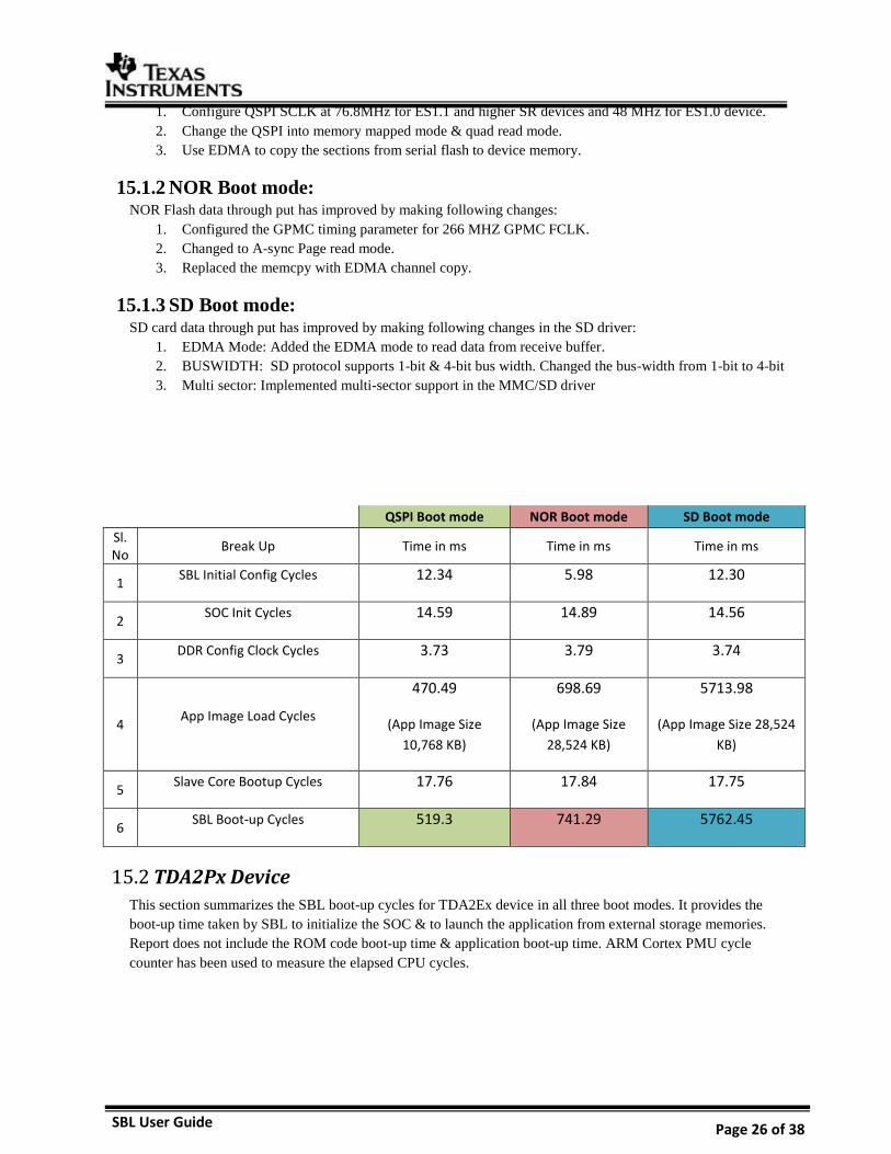
SBL User Guide Page 26 of 38
1. Configure QSPI SCLK at 76.8MHz for ES1.1 and higher SR devices and 48 MHz for ES1.0 device.
2. Change the QSPI into memory mapped mode & quad read mode.
3. Use EDMA to copy the sections from serial flash to device memory.
15.1.2 NOR Boot mode: NOR Flash data through put has improved by making following changes:
1. Configured the GPMC timing parameter for 266 MHZ GPMC FCLK.
2. Changed to A-sync Page read mode.
3. Replaced the memcpy with EDMA channel copy.
15.1.3 SD Boot mode: SD card data through put has improved by making following changes in the SD driver:
1. EDMA Mode: Added the EDMA mode to read data from receive buffer.
2. BUSWIDTH: SD protocol supports 1-bit & 4-bit bus width. Changed the bus-width from 1-bit to 4-bit
3. Multi sector: Implemented multi-sector support in the MMC/SD driver
QSPI Boot mode NOR Boot mode SD Boot mode
Sl.No
Break Up Time in ms Time in ms Time in ms
1 SBL Initial Config Cycles 12.34 5.98 12.30
2 SOC Init Cycles 14.59 14.89 14.56
3 DDR Config Clock Cycles 3.73 3.79 3.74
4 App Image Load Cycles
470.49
(App Image Size
10,768 KB)
698.69
(App Image Size
28,524 KB)
5713.98
(App Image Size 28,524
KB)
5 Slave Core Bootup Cycles 17.76 17.84 17.75
6 SBL Boot-up Cycles 519.3 741.29 5762.45
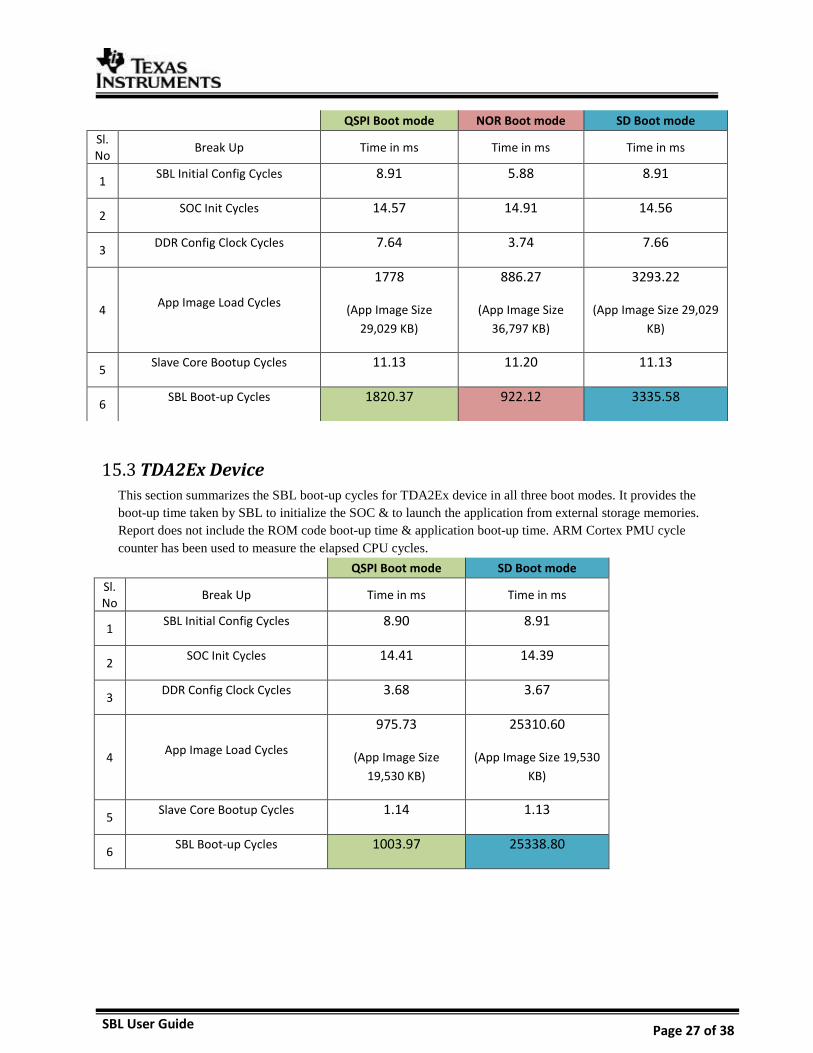
TDA2Px Device 15.2
This section summarizes the SBL boot-up cycles for TDA2Ex device in all three boot modes. It provides the
boot-up time taken by SBL to initialize the SOC & to launch the application from external storage memories.
Report does not include the ROM code boot-up time & application boot-up time. ARM Cortex PMU cycle
counter has been used to measure the elapsed CPU cycles.
SBL User Guide Page 27 of 38
TDA2Ex Device 15.3
This section summarizes the SBL boot-up cycles for TDA2Ex device in all three boot modes. It provides the
boot-up time taken by SBL to initialize the SOC & to launch the application from external storage memories.
Report does not include the ROM code boot-up time & application boot-up time. ARM Cortex PMU cycle
counter has been used to measure the elapsed CPU cycles.
QSPI Boot mode SD Boot mode
Sl.No
Break Up Time in ms Time in ms
1 SBL Initial Config Cycles 8.90 8.91
2 SOC Init Cycles 14.41 14.39
3 DDR Config Clock Cycles 3.68 3.67
4 App Image Load Cycles
975.73
(App Image Size
19,530 KB)
25310.60
(App Image Size 19,530
KB)
5 Slave Core Bootup Cycles 1.14 1.13
6 SBL Boot-up Cycles 1003.97 25338.80
QSPI Boot mode NOR Boot mode SD Boot mode
Sl.No
Break Up Time in ms Time in ms Time in ms
1 SBL Initial Config Cycles 8.91 5.88 8.91
2 SOC Init Cycles 14.57 14.91 14.56
3 DDR Config Clock Cycles 7.64 3.74 7.66
4 App Image Load Cycles
1778
(App Image Size
29,029 KB)
886.27
(App Image Size
36,797 KB)
3293.22
(App Image Size 29,029
KB)
5 Slave Core Bootup Cycles 11.13 11.20 11.13
6 SBL Boot-up Cycles 1820.37 922.12 3335.58
SBL User Guide Page 28 of 38
TDA2Ex_17x17 Device 15.4
This section summarizes the SBL boot-up cycles for TDA2Ex 17x17 device in all three boot modes. It provides
the boot-up time taken by SBL to initialize the SOC & to launch the application from external storage memories.
Report does not include the ROM code boot-up time & application boot-up time. ARM Cortex PMU cycle
counter has been used to measure the elapsed CPU cycles.
SBL User Guide Page 29 of 38
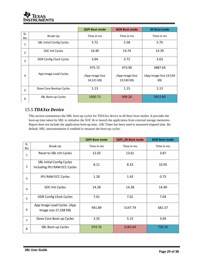
TDA3xx Device 15.5
This section summarizes the SBL boot-up cycles for TDA3xx device in all three boot modes. It provides the
boot-up time taken by SBL to initialize the SOC & to launch the application from external storage memories.
Report does not include the application boot-up time. 32K Timer has been used to measured elapsed time. By
default, SBL instrumentation is enabled to measure the boot-up cycles.
QSPI Boot mode QSPI_SD Boot mode NOR Boot mode
Sl.No
Break Up Time in ms Time in ms Time in ms
1 Reset to SBL Init Cycles 12.02 13.61 3.87
2
SBL Initial Config Cycles
Including IPU RAM ECC Cycles 8.11 8.33 10.95
3 IPU RAM ECC Cycles 1.28 1.43 0.73
4 SOC Init Cycles 14.28 14.28 14.40
5 DDR Config Clock Cycles 7.01 7.01 7.04
6
App Image Load Cycles (App
Image size 27,338 KB) 941.89 5147.79 681.57
7 Slave Core Boot-up Cycles 3.35 5.15 3.69
8 SBL Boot-up Cycles 974.76 5182.64 730.16
QSPI Boot mode NOR Boot mode SD Boot mode
Sl.No
Break Up Time in ms Time in ms Time in ms
1 SBL Initial Config Cycles 5.72 5.58 5.70
2 SOC Init Cycles 14.40 14.74 14.39
3 DDR Config Clock Cycles 3.64 3.72 3.63
4 App Image Load Cycles
975.72
(App Image Size
24,521 KB)
473.90
(App Image Size
19,530 KB)
3887.64
(App Image Size 19,530
KB)
5 Slave Core Bootup Cycles 1.13 1.15 1.13
6 SBL Boot-up Cycles 1000.73 499.20 3912.60
SBL User Guide Page 30 of 38
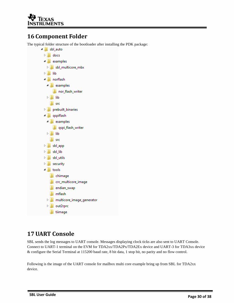
16 Component Folder The typical folder structure of the bootloader after installing the PDK package:
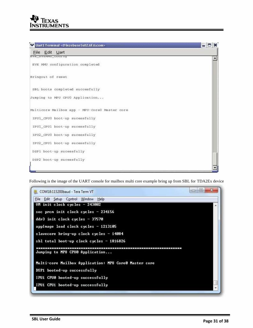
17 UART Console SBL sends the log messages to UART console. Messages displaying clock ticks are also sent to UART Console.
Connect to UART-1 terminal on the EVM for TDA2xx/TDA2Px/TDA2Ex device and UART-3 for TDA3xx device
& configure the Serial Terminal at 115200 baud rate, 8 bit data, 1 stop bit, no parity and no flow control.
Following is the image of the UART console for mailbox multi core example bring up from SBL for TDA2xx
device.
SBL User Guide Page 31 of 38
Following is the image of the UART console for mailbox multi core example bring up from SBL for TDA2Ex device
SBL User Guide Page 32 of 38
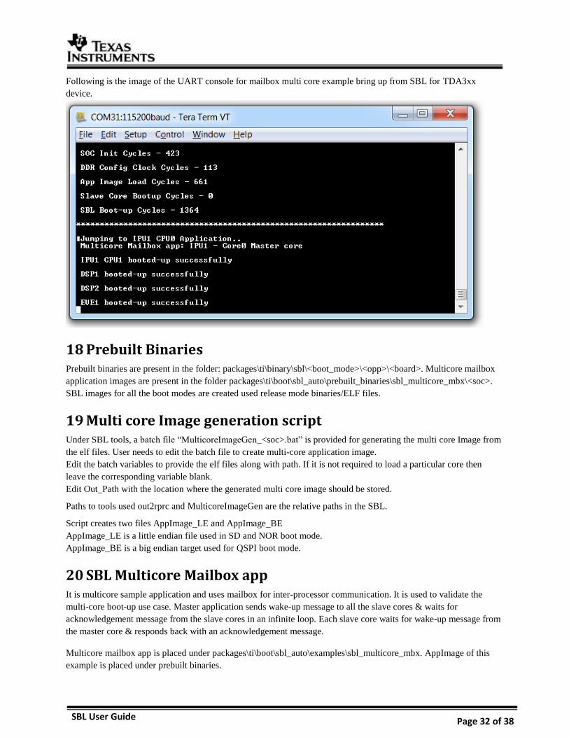
Following is the image of the UART console for mailbox multi core example bring up from SBL for TDA3xx
device.
18 Prebuilt Binaries Prebuilt binaries are present in the folder: packages\ti\binary\sbl\<boot_mode>\<opp>\<board>. Multicore mailbox
application images are present in the folder packages\ti\boot\sbl_auto\prebuilt_binaries\sbl_multicore_mbx\<soc>.
SBL images for all the boot modes are created used release mode binaries/ELF files.
19 Multi core Image generation script Under SBL tools, a batch file “MulticoreImageGen_<soc>.bat” is provided for generating the multi core Image from
the elf files. User needs to edit the batch file to create multi-core application image.
Edit the batch variables to provide the elf files along with path. If it is not required to load a particular core then
leave the corresponding variable blank.
Edit Out_Path with the location where the generated multi core image should be stored.
Paths to tools used out2rprc and MulticoreImageGen are the relative paths in the SBL.
Script creates two files AppImage_LE and AppImage_BE
AppImage_LE is a little endian file used in SD and NOR boot mode.
AppImage_BE is a big endian target used for QSPI boot mode.
20 SBL Multicore Mailbox app It is multicore sample application and uses mailbox for inter-processor communication. It is used to validate the
multi-core boot-up use case. Master application sends wake-up message to all the slave cores & waits for
acknowledgement message from the slave cores in an infinite loop. Each slave core waits for wake-up message from
the master core & responds back with an acknowledgement message.
Multicore mailbox app is placed under packages\ti\boot\sbl_auto\examples\sbl_multicore_mbx. AppImage of this
example is placed under prebuilt binaries.
SBL User Guide Page 33 of 38
21 HS device support
Memory map 21.1
SBL should not use OCMC_RAM1 from address 0x4030_000 to 0x4030_1350. The entry point will be set
to 0x4030_1350. The GP-Header in SBL which indicates entry point and size of SBL is not needed when
generating the boot-image using MShield-DK.
If entry point is provided as 0xFFFFFFFF to the tiimage utility, the GP Header will not be
appended at the top of the MLO.
Boot authentication 21.2
SBL binary generated needs to be signed and merged with PPA using MShield-DK package.
21.2.1 Setting up MShield-DK/SECDEV for TDA2x
MShield-DK/SECDEV package is supported only on Linux/Ubuntu machines. This applies to
building PPA, signing boot-images and application images.
Extract the MShield-DK/SECDEV package into the VisionSDK installation directory. The
“vision_sdk”, “ti_components” and “mshield-dk_std_x_x_x” folder should be at same level.
GCC compiler installation details from MShield-DK/SECDEV documentation
If you need to re-generate the PPA or PA using GCC, these are the compilers tested
DRA7xx/72x: GCC 4.8.2 arm-linux-gnueabihf-gcc cross compiler under Ubuntu 14.04 64-bit
(arm-linux-gnueabihf-gcc (Ubuntu/Linaro 4.8.2-16ubuntu4) 4.8.2)
DRA7xx/72x: GCC 4.8 arm-eabi-gcc bare-metal cross compiler from TI Android SDK (arm-
eabi-gcc (GCC) 4.8)
The CROSS_COMPILE environment variable will be used, if it is defined, to prefix the gcc build
calls. If it is not defined, the value 'arm-linux-gnueabihf-' will be used. The arm-linux-gnueabihf-
gcc compiler can be installed under Ubuntu using the 'sudo apt-get gcc-arm-linux-gnueabihf'
command.
We will refer to the MShield-DK/SECDEV directory by the environment variable
MSHIELD_DK_DIR.
Setting up TDA2x configuration
o Run the following commands:
cd $MSHIELD_DK_DIR/src perl config.pl
SBL User Guide Page 34 of 38
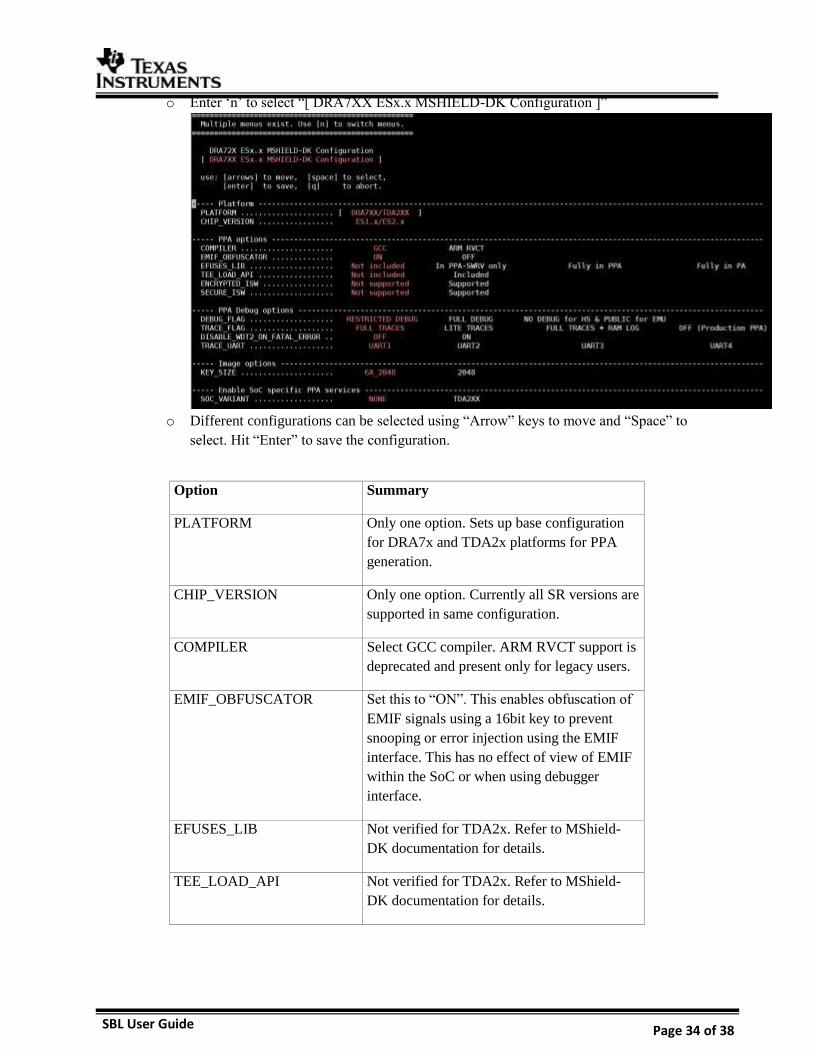
o Enter ‘n’ to select “[ DRA7XX ESx.x MSHIELD-DK Configuration ]”
o Different configurations can be selected using “Arrow” keys to move and “Space” to
select. Hit “Enter” to save the configuration.
Option Summary
PLATFORM Only one option. Sets up base configuration
for DRA7x and TDA2x platforms for PPA
generation.
CHIP_VERSION Only one option. Currently all SR versions are
supported in same configuration.
COMPILER Select GCC compiler. ARM RVCT support is
deprecated and present only for legacy users.
EMIF_OBFUSCATOR Set this to “ON”. This enables obfuscation of
EMIF signals using a 16bit key to prevent
snooping or error injection using the EMIF
interface. This has no effect of view of EMIF
within the SoC or when using debugger
interface.
EFUSES_LIB Not verified for TDA2x. Refer to MShield-
DK documentation for details.
TEE_LOAD_API Not verified for TDA2x. Refer to MShield-
DK documentation for details.
SBL User Guide Page 35 of 38
ENCRYPTED_ISW Will assume the boot-image includes SBL in
encrypted form.
SECURE_ISW Keep as “Not supported”. This transfers
control to SBL in while keeping the A15 in
secure-mode. Refer to MShield-DK
documentation for relevant use-cases.
DEBUG_FLAG “RESTRICTED DEBUG” prevents any
debugger connection via the JTAG interface.
“FULL DEBUG” allows users to connect to
CCS for all software.
“NO DEBUG for HS & PUBLIC for EMU”
prevents JTAG access when SECURE
software is executing, but allow JTAG access
for rest of the software.
TRACE_LOG Select trace level as needed.
DISABLE_WDT2_ON_FATA
L_ERROR
Disable/Enable watchdog timer after a fatal
error.
TRACE_UART Select which UART interface to use for
ROM/PPA traces. TI EVM supports only
UART1 interface.
KEY_SIZE Keep as 6X_2048. Refer to MShield-DK
documentation for details.
SOC_VARIANT Select “TDA2XX” if you working with RTOS
on A15. This enables some PPA services to
enable firewall usage from RTOS
environment.
Caution: If you are using HLOS like Linux on
a TDA2x device, select SOC_VARIANT =
“NONE”. This is because the PPA services
introduced by “TDA2XX” option should only
be used when all software is authenticated.
This may not be guaranteed in an HLOS
environment.
o If you enable ENCRYPTED_ISW, you need to modify
reference/dra7xx/config/KEY_6X_2048/isw_m.cfg
SBL User Guide Page 36 of 38
Uncomment the lines:
For TDA2x, only ISW_TYPE=1 is verified. This selects the key used for encryption
ISW/SBL encryption. The key can be the device MEK, a key derived from the device
MEK, the device CEK, or a key derived from the device CEK. Refer to MShield-DK
documentation for details on these options. The default keys in this file are TI Dummy
Keys.
21.2.2 Boot-Image (PPA + SBL) generation o Setup MShield-DK/SECDEV for TDA2XX
o Build PPA using the following command
o SD-BOOT: Create boot image using following commands:
(Input file: unsigned_MLO, Output file: MLO – Both are in little-endian format)
Note: Boot-Image for SD-BOOT must have the MLO as the first argument
o QSPI-BOOT Create boot image using following commands
(Input file: unsigned_XLOADER, Output file: XLOADER – Both are in little-endian
format)
Note: Boot-Image for QSPI-BOOT must have the XLOADER as the first argument
o In case of starterware, the qspiFlashWriter application expects input in big-endian
format. This can be done in Linux using the following command
21.2.3 Signing AppImages o MShield-DK provides an image-signing tool to sign any binary image
o A signed image contains the original data padded with zero to reach a 4 byte aligned size,
followed by a 280 byte of signature.
ISW_TYPE = "0x00000001"
ISW_ENC_IV = "000102030405060708090a0b0c0d0e0f"
ISW_ENC_KEY = "0828F4E5A4C5B20F119A631517C623CCA2752BBD639D150A12F26EC5923B3E86"
cd $MSHIELD_DK_DIR/src perl config.pl
cd $MSHIELD_DK_DIR/scripts ./ift-ppa-gen.sh dra7xx
cd $MSHIELD_DK_DIR/scripts ./create-boot-image.sh MLO unsigned_MLO MLO
cd $MSHIELD_DK_DIR/scripts ./create-boot-image.sh X-LOADER unsigned_XLOADER XLOADER
xxd -p -c 4 inp_LE | sed "s/\(..\)\(..\)\(..\)\(..\)/\4\3\2\1/" | xxd -r –p > out_BE
SBL User Guide Page 37 of 38
o This can be generated using the following command
o AppImage formats can be customized by users as needed. There are two formats of Multi-
core application image: ‘V2 i.e. Version 2’ and ‘Version 1 i.e. V1’. The details of these
formats are given in SBL Library header file. TI SBL support boot on HS devices that are
built with newer i.e. “Version 2” format.
22 Flashing production binaries using – mflash It is a windows PC based a tool that allows users to flash binaries to production boards. PDK supports
counter part of the mflash which is a special SBL that enables UART boot mode and transfer of
production SBL and application image (AppImage) over UART.
22.1.1 PC side setup
Kindly download mflash_0.1.zip from CDDS. Please refer mflash\doc\AppNote_mflash.pdf for PC side
setup and build details.
22.1.2 Build steps
SBL supports UART boot mode only for TDA3x.
22.1.3 Generating mflash SBL
There are script files under <pdk>/packages/ti/boot/sbl_auto/tools/mflash
These will help you generate sbl_mflash
Sbl_mflash needs to be used along with PC side mflash tool to send it over UART.
For more information on hardware setup/switch settings please refer the AppNote
mflash\doc\AppNote_mflash.pdf in mflash package.
23 Known Issues Please refer to the package release notes for the list of open issues & issues closed in the current release.
cd $MSHIELD_DK_DIR/scripts ./ift-image-sign.sh dra7xx input_binary output_binary
make -s -j sbl BOARD=tda3xx-evm BOOTMODE=uart SBL_TYPE=mflash
sbl_mflash_create_tda3xx.sh
sbl_mflash_create_tda3xx.bat
SBL User Guide Page 38 of 38
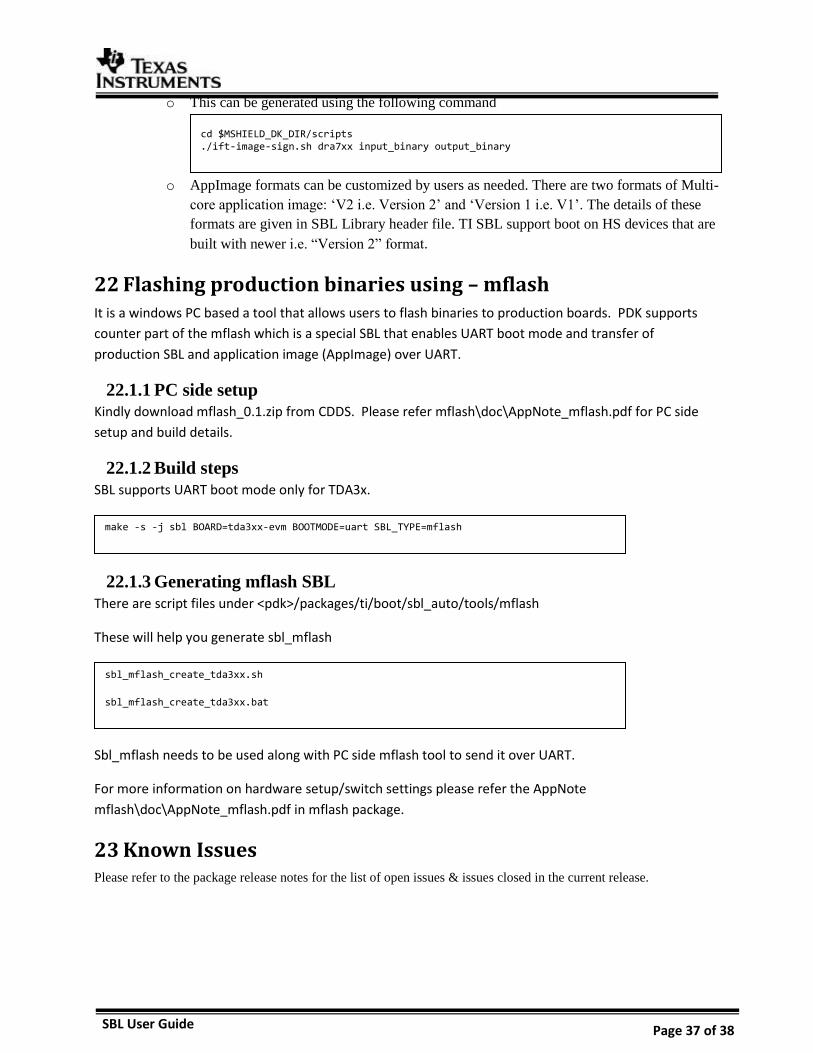
24 Revision History
Version Date Status Author Revision History
1.0 2-JULY-17 Approved Rishabh SBL User guide for TDA2xx, TDA2Ex and TDA3xx with Performance numbers and details required to run/build/user SBL
1.1 12-OCT-17 Approved Ankur Added details for TDA2Px device