Embed Size (px)
Citation preview
1
SCADA/ICS
Supervisory Control and Data Acquisition (SCADA)
Industrial Control System (ICS)
(brought to you by RMRoberts.com)
In the first article we are providing.is newsletter we are providing an article
covering changes to Domain 1.7
There are several new terms and acronyms listed under Domain 1.7.
SCADA/ICS
ICS server
DCS/Closed Network
Remote Terminal Unit
Programmable Logic Controller
Industrial and Manufacturing Network Systems
Industrial and manufacturing systems incorporate network devices, media and
technology in automated systems. The network systems and application were
developed separately from typical networks used in business for data systems.
As a result of the separate development, some of the terms and devices now
have a somewhat different definition, as compared to data networking
terminology. First, we will take a look at the overall network system encountered
in industrial applications and automation systems.
Note: This section uses terminology as defined by the National Institute of
Standards and Technology (NIST) under the U.S. Department of Commerce.
Programmable Logic Controller
In the early days of computer development, the Programmable Logic Controller
(PLC) was a specialized small computer designed to replace existing automation
control devices. Originally, early automated systems use in manufacturing and
2
industrial process plants were based upon using electromechanical relays, as
well as mechanically operated timers, mechanical counters and switches.
The early control systems designed with relays were referred to as relay logic
control systems or relay logic systems. The relays were wired together with
switches and timers to form automated manufacturing system of an industrial
process. Hundreds or even thousands of electromagnetic devices were used to
create a completely automated manufacturing plant.
With the invention of the transistor devices, new items such as miniature
computers were invented. Industrial computers were designed to replace the
electromechanical devices such as relays and mechanical timers, and to gather
data (information) such as speed of motors, temperature, flow rates, volume of
materials and such. The early industrial computers were called PLC or
Programmable Logic Controllers.
The name Programmable Logic Controller reflects the purpose of the industrial
computer. The PLC was programmable, which meant the input and output
connections associated with the PLC could be programed using specialized
software and be designated the purpose of connections associated with PLC as
a switch, or a timer, or a counter and more. Relays used to create logic control
systems were no longer needed.
The PLC proved to be more economical than relay logic systems. The PLC was
more dependable because there was no failure due to excessive wear as with
mechanical devices such as relays and mechanical timers. The PLC and
associated devices that do not use moving parts, could be tightly sealed in an
epoxy like material, thus making them impervious to dust, debris, rust or
moisture.
In order to make a change in the industrial control process using relay logic type
of control system, the technician was required to physically rewire the relay
system and possible add additional relays and timers. When using a PLC, the
technician simply modifies the program, which automatically makes changes to
the control system. There is no need for physical control device to be rewired.
PLCs use proprietary software which is designed especially for industrial and
manufacturing systems such as oil refineries, electrical power production and
electrical distribution systems, water systems, automobile manufacturing, food
3
processing plants, chemical plants and more. PLCs were not designed for
software applications like the personal computer (PC).
To properly program a PLC, a basic understanding of electrical devices such as
motors, limit switches, actuators and more is required.
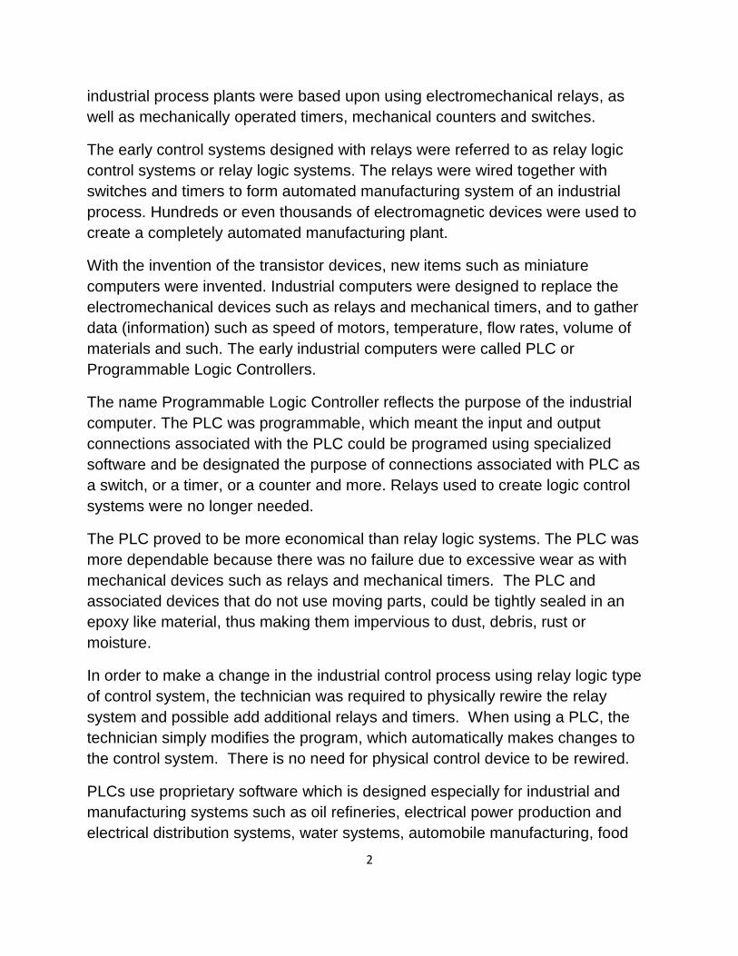
Figure 1 - Lenze motion controller with programmable logic controller (PLC)
See the link: http://www.lenze.com/en-us/products/controls/controller-c300/
The Original Programmable Logic Controller (PLC)
The original PLC was a small dedicated industrial computer designed to replace
the functions executed by electromechanical hardware (relays, switches, and
mechanical timer/counters). PLCs are typically found throughout large and small
SCADA and DCS systems. The two acronyms SCADA/ICS stand for
“Supervisory Control and Data Acquisition” (SCADA) and “Industrial Control
System” (ICS). These terms are used when describing large manufacturing
plants and industrial processing plants.
4
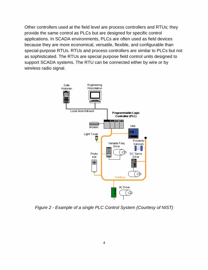
Other controllers used at the field level are process controllers and RTUs; they
provide the same control as PLCs but are designed for specific control
applications. In SCADA environments, PLCs are often used as field devices
because they are more economical, versatile, flexible, and configurable than
special-purpose RTUs. RTUs and process controllers are similar to PLCs but not
as sophisticated. The RTUs are special purpose field control units designed to
support SCADA systems. The RTU can be connected either by wire or by
wireless radio signal.
Figure 2 - Example of a single PLC Control System (Courtesy of NIST)
5
Industrial Control System Network Architecture
Again, the two acronyms are (SCADA) “Supervisory Control and Data
Acquisition,” and (ICS) Industrial Control System.
Note: The acronym ICS also represents Internet Connection Sharing.
The term supervisory control and data acquisition (SCADA) means that the
control of the plant is controlled and monitored electronically, “supervisory
control,” and data about the process is gathered, “data acquisition.” The data
acquisition is used to monitor inventory of product and to control production
rates.
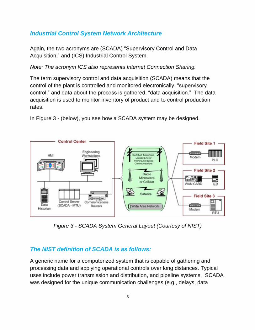
In Figure 3 - (below), you see how a SCADA system may be designed.
Figure 3 - SCADA System General Layout (Courtesy of NIST)
The NIST definition of SCADA is as follows:
A generic name for a computerized system that is capable of gathering and
processing data and applying operational controls over long distances. Typical
uses include power transmission and distribution, and pipeline systems. SCADA
was designed for the unique communication challenges (e.g., delays, data
6
integrity) that are posed by the various media that must be used, such as phone
lines, microwave, and satellite. Usually, these are shared rather than dedicated.
Control Center
The control center portion of the SCADA consists of Human Machine Interface
(HMI), engineering workstations, data historian, control server, and
communications routers. These items work together to control and record data
about the system or process.
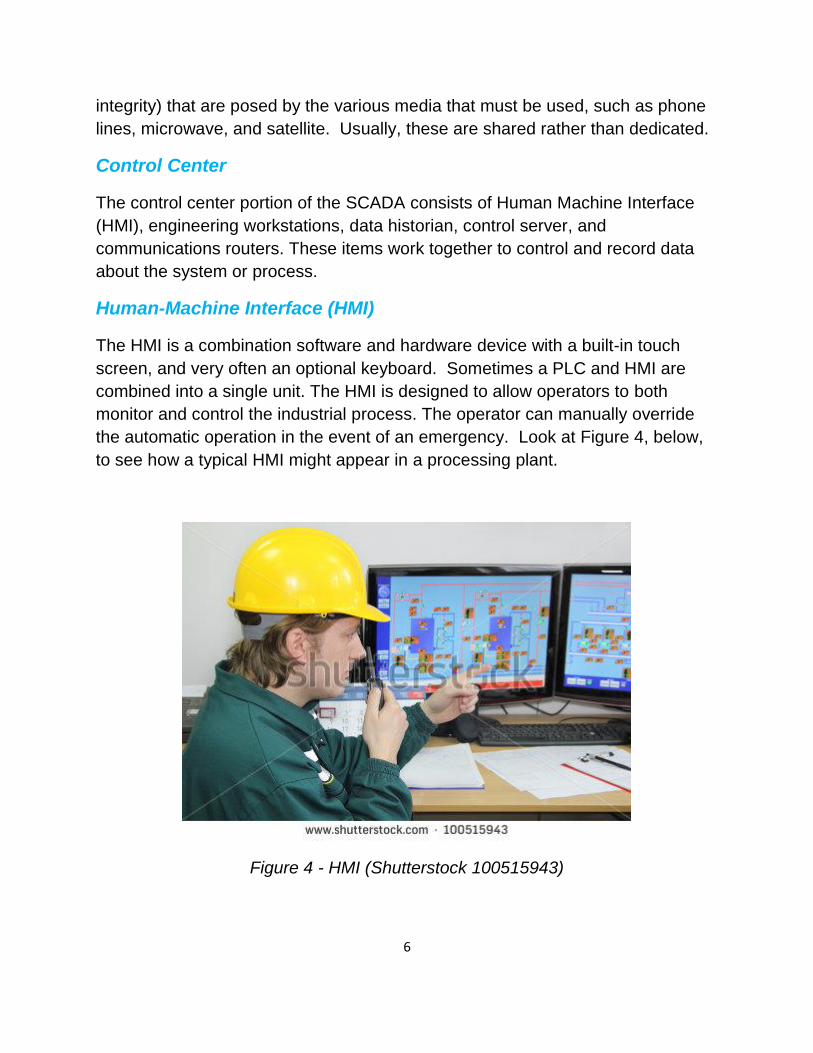
Human-Machine Interface (HMI)
The HMI is a combination software and hardware device with a built-in touch
screen, and very often an optional keyboard. Sometimes a PLC and HMI are
combined into a single unit. The HMI is designed to allow operators to both
monitor and control the industrial process. The operator can manually override
the automatic operation in the event of an emergency. Look at Figure 4, below,
to see how a typical HMI might appear in a processing plant.
Figure 4 - HMI (Shutterstock 100515943)
7
Data Historian
The data historian is a centralized database for logging all process information
within an ICS. Information stored in this database can be accessed to support
various analyses, from statistical process control to enterprise level planning.
SCADA Server or Master Terminal Unit (MTU)
The SCADA Server is the device that acts as the master in a SCADA system.
Remote terminal units and PLC devices located at remote field sites usually act
as slaves for the SCADA master terminal.
Communications Routers
A router is a communications device that transfers and or translates data and
commands between two dissimilar networks. Common uses for routers include
connecting a LAN to a WAN, and connecting MTUs, and RTUs to a long-distance
network medium for SCADA communication. This definition is similar to data
network definition of a router, but is more appropriate for an industrial type of
network such as a SCADA.
The manufacturing or process plant may cover large areas and require a wide
area network for support. The wide area network could utilize telephone lines,
power lines, radio microwave or cellular phone system or even satellite system.
The wide area network could even be use more than one type of network media
and more than on network topography.
8
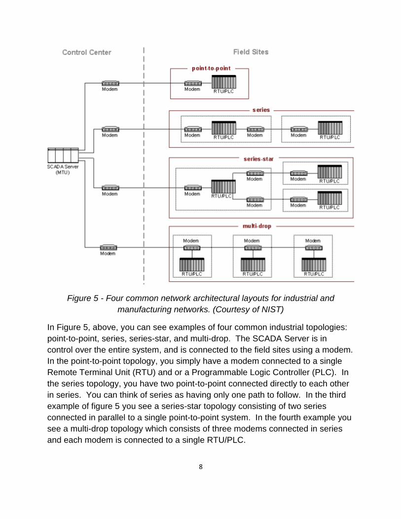
Figure 5 - Four common network architectural layouts for industrial and
manufacturing networks. (Courtesy of NIST)
In Figure 5, above, you can see examples of four common industrial topologies:
point-to-point, series, series-star, and multi-drop. The SCADA Server is in
control over the entire system, and is connected to the field sites using a modem.
In the point-to-point topology, you simply have a modem connected to a single
Remote Terminal Unit (RTU) and or a Programmable Logic Controller (PLC). In
the series topology, you have two point-to-point connected directly to each other
in series. You can think of series as having only one path to follow. In the third
example of figure 5 you see a series-star topology consisting of two series
connected in parallel to a single point-to-point system. In the fourth example you
see a multi-drop topology which consists of three modems connected in series
and each modem is connected to a single RTU/PLC.
9
DISTRIBUTED CONTROL SYSTEM (DCS)
A Distributed Control System (DCS) is a system comprised of independently control
groups of devices spread across the entire processing or manufacturing system. In a
DCS system, a centralized controller is not required to control the process of any one
particular section. DCS is often presented as a “closed system” which means that the
DCS can operate autonomously. The closed network does not require a centralized
server to control the operation of a DCS. The primary function of the control center is
used to gather data and share data rather than directly control all process and
manufacturing devices.
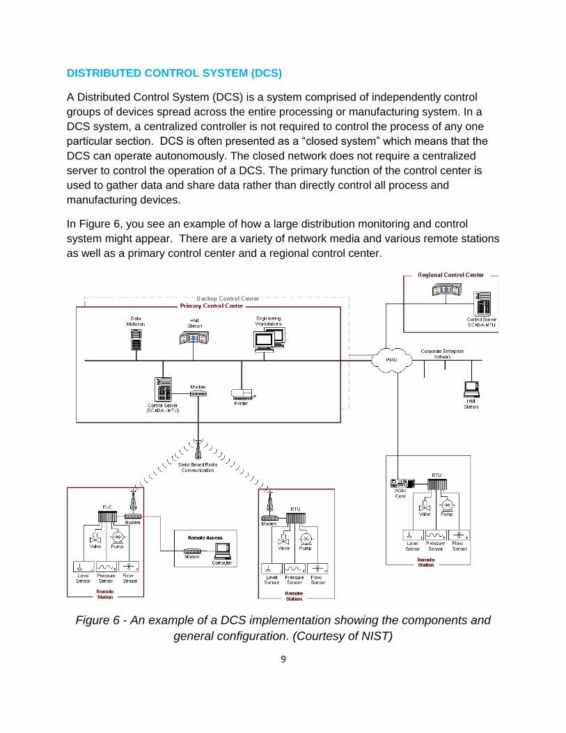
In Figure 6, you see an example of how a large distribution monitoring and control
system might appear. There are a variety of network media and various remote stations
as well as a primary control center and a regional control center.
Figure 6 - An example of a DCS implementation showing the components and
general configuration. (Courtesy of NIST)
10
There are three remote stations each with a pump and level, pressure and flow sensors. Each remote station is independent of the other two remote stations. Any of the three controllers can fail without affecting the other controllers. The three remote stations function independently of each other. They each have their own closed network system that does not require devices from any other section.
Remote Terminal Unit A Remote Terminal Unit (RTU) is an electronic device used to support communication between a remote station and a control center. A remote terminal unit differs from a PLC in the fact that the PLC is a more sophisticated electronic device that can not only support communication between the remote station and the control center but can also be used to control all functions of the remote station. To learn more about SCADA/ICS use the following link. https://www.tofinosecurity.com/blog/scada-security-basics-scada-vs-ics-terminology Guide to Industrial Control Systems (ICS) Security provided by the federal government. http://nvlpubs.nist.gov/nistpubs/SpecialPublications/NIST.SP.800-82r1.pdf Siemens white paper comparing PLC and DCS. http://w3.siemens.com/mcms/process-control-systems/SiteCollectionDocuments/efiles/pcs7/support/marktstudien/PLC_or_DCS.pdf
11
Review Questions
1. What does the acronym SCADA represent? 2. What is another name and acronym for a SCADA Server? 3. What is “relay logic control? 4. What computer device was designed to replace relay logic controlled systems? 5. What is the function of a RTU? 6. How does a RTU differ when compared to a PLC? 7. What does the acronym HMI represent? 8. What is the purpose of the HMI? 9. What are the four common network architectural layouts for industrial and manufacturing networks? 10. What does the acronym DCS represent? 11. What is a distributed control system? 12. How does a DCS differ from a SCADA?
12
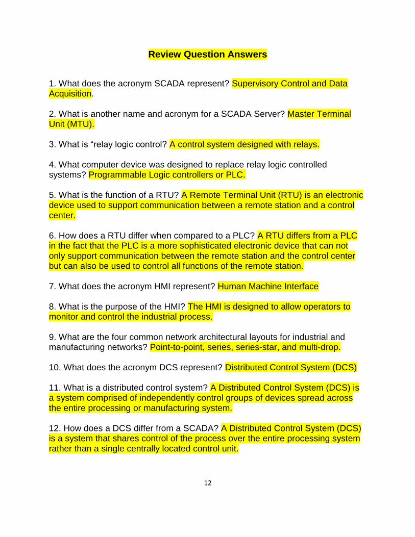
Review Question Answers
1. What does the acronym SCADA represent? Supervisory Control and Data Acquisition. 2. What is another name and acronym for a SCADA Server? Master Terminal Unit (MTU). 3. What is “relay logic control? A control system designed with relays. 4. What computer device was designed to replace relay logic controlled systems? Programmable Logic controllers or PLC. 5. What is the function of a RTU? A Remote Terminal Unit (RTU) is an electronic device used to support communication between a remote station and a control center. 6. How does a RTU differ when compared to a PLC? A RTU differs from a PLC in the fact that the PLC is a more sophisticated electronic device that can not only support communication between the remote station and the control center but can also be used to control all functions of the remote station. 7. What does the acronym HMI represent? Human Machine Interface 8. What is the purpose of the HMI? The HMI is designed to allow operators to monitor and control the industrial process. 9. What are the four common network architectural layouts for industrial and manufacturing networks? Point-to-point, series, series-star, and multi-drop. 10. What does the acronym DCS represent? Distributed Control System (DCS) 11. What is a distributed control system? A Distributed Control System (DCS) is a system comprised of independently control groups of devices spread across the entire processing or manufacturing system. 12. How does a DCS differ from a SCADA? A Distributed Control System (DCS) is a system that shares control of the process over the entire processing system rather than a single centrally located control unit.