Embed Size (px)
Citation preview
APRILIA WOULD LIKE TO THANK YOU
for choosing one of its products. We have drawn up this booklet to provide a comprehensive overview of your vehicle's quality features. Please read itcarefully before riding the vehicle for the first time. It contains information, tips and precautions for using your vehicle It also describes features, detailsand devices to assure you that you have made the right choice. We believe that if you follow our suggestions, you will soon get to know your new vehiclewell and will use it for a long time at full satisfaction. This booklet is an integral part of the vehicle, and should the vehicle be sold, it must be transferredto the new owner.
SCARABEO 125 - 200
Ed. 03 2008
The instructions given in this manual are intended to provide a clear, simple guide to using your vehicle; it also describes routine maintenance proceduresand regular checks that should be carried out on the vehicle at an Aprilia Dealer or Authorised Workshop. The booklet also contains instructions forsimple repairs. Any operations not specifically described in this booklet require the use of special tools and/or particular technical knowledge: for theseoperations, please take your vehicle to an Aprilia Dealer or Authorised Workshop.
2
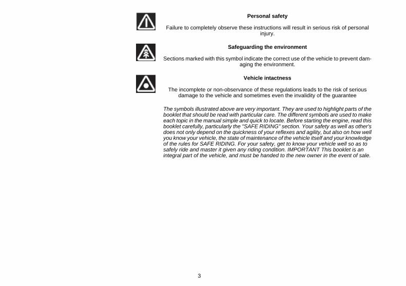
Personal safety
Failure to completely observe these instructions will result in serious risk of personalinjury.
Safeguarding the environment
Sections marked with this symbol indicate the correct use of the vehicle to prevent dam-aging the environment.
Vehicle intactness
The incomplete or non-observance of these regulations leads to the risk of seriousdamage to the vehicle and sometimes even the invalidity of the guarantee
The symbols illustrated above are very important. They are used to highlight parts of thebooklet that should be read with particular care. The different symbols are used to makeeach topic in the manual simple and quick to locate. Before starting the engine, read thisbooklet carefully, particularly the "SAFE RIDING" section. Your safety as well as other'sdoes not only depend on the quickness of your reflexes and agility, but also on how wellyou know your vehicle, the state of maintenance of the vehicle itself and your knowledgeof the rules for SAFE RIDING. For your safety, get to know your vehicle well so as tosafely ride and master it given any riding condition. IMPORTANT This booklet is anintegral part of the vehicle, and must be handed to the new owner in the event of sale.
3

4
INDEX
GENERAL RULES....................................................................... 7Information to recycle the scooter............................................. 8
VEHICLE...................................................................................... 11Arrangement of the main components...................................... 14Dashboard................................................................................ 17Analogue instrument panel....................................................... 19Digital lcd display...................................................................... 21
"MODE" button...................................................................... 22Key switch................................................................................. 23
Locking the steering wheel.................................................... 24Switch direction indicators........................................................ 25Horn button............................................................................... 25Light switch............................................................................... 25Start-up button.......................................................................... 26Engine stop button.................................................................... 26Power supply socket................................................................. 28
Opening the saddle............................................................... 28Identification.............................................................................. 29Rear top box opening................................................................ 31
USE.............................................................................................. 33Checks...................................................................................... 34Shock absorber adjustment...................................................... 36Starting up the engine............................................................... 38Difficult start up......................................................................... 43Stopping the engine.................................................................. 43Catalytic silencer....................................................................... 45Stand......................................................................................... 46Suggestions to prevent theft..................................................... 46Safe driving............................................................................... 47
MAINTENANCE........................................................................... 53Engine oil level.......................................................................... 54
Engine oil level check............................................................ 55Engine oil top-up................................................................... 56
Warning light (insufficient oil pressure)................................. 57Engine oil change.................................................................. 57
Tyres......................................................................................... 59Spark plug dismantlement........................................................ 61Removing the air filter............................................................... 63Air filter cleaning....................................................................... 64Cooling fluid level...................................................................... 65Checking the brake oil level...................................................... 70Battery....................................................................................... 72
Use of a new battery............................................................. 76Long periods of inactivity.......................................................... 77Lamps....................................................................................... 78Front light group........................................................................ 79
Headlight adjustment............................................................. 83Front direction indicators........................................................... 84Rear optical unit........................................................................ 85Number plate light..................................................................... 87Rear-view mirrors...................................................................... 87Idle adjustment.......................................................................... 88Front and rear disc brake.......................................................... 89Inactivity of the vehicle.............................................................. 91Cleaning the vehicle.................................................................. 92Transport................................................................................... 94
TECHNICAL DATA...................................................................... 97Kit equipment............................................................................ 102
PROGRAMMED MAINTENANCE............................................... 105Scheduled maintenance table................................................... 106
SPECIAL FITTINGS..................................................................... 113Sidestand.................................................................................. 114Luggage rack............................................................................ 114Windscreen............................................................................... 115
5

6

SCARABEO 125 - 200Chap. 01
General rules
7
01_01
01_02
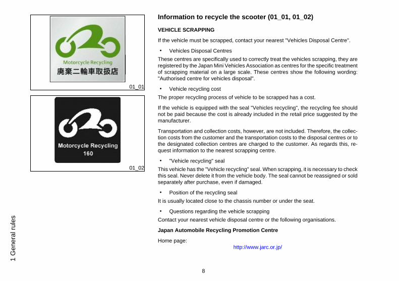
Information to recycle the scooter (01_01, 01_02)
VEHICLE SCRAPPING
If the vehicle must be scrapped, contact your nearest "Vehicles Disposal Centre".
• Vehicles Disposal CentresThese centres are specifically used to correctly treat the vehicles scrapping, they areregistered by the Japan Mini Vehicles Association as centres for the specific treatmentof scrapping material on a large scale. These centres show the following wording:"Authorised centre for vehicles disposal".
• Vehicle recycling costThe proper recycling process of vehicle to be scrapped has a cost.
If the vehicle is equipped with the seal "Vehicles recycling", the recycling fee shouldnot be paid because the cost is already included in the retail price suggested by themanufacturer.
Transportation and collection costs, however, are not included. Therefore, the collec-tion costs from the customer and the transportation costs to the disposal centres or tothe designated collection centres are charged to the customer. As regards this, re-quest information to the nearest scrapping centre.
• "Vehicle recycling" sealThis vehicle has the "Vehicle recycling" seal. When scrapping, it is necessary to checkthis seal. Never delete it from the vehicle body. The seal cannot be reassigned or soldseparately after purchase, even if damaged.
• Position of the recycling sealIt is usually located close to the chassis number or under the seat.
• Questions regarding the vehicle scrappingContact your nearest vehicle disposal centre or the following organisations.
Japan Automobile Recycling Promotion Centre
Home page:http://www.jarc.or.jp/
8
1 G
ener
al ru
les
Japan Automobile Recycling Promotion Centre call centre for vehicles recy-cling
Telephone: 03-3598-8075
Time: From 9:30 am to 5:00 pm (Except holidays, weekends and the first and last dayof the year.)
9
1 General rules

10
1 G
ener
al ru
les
SCARABEO 125 - 200Chap. 02
Vehicle
11
02_01
12
2 Ve
hicl
e
02_02
13
2 Vehicle
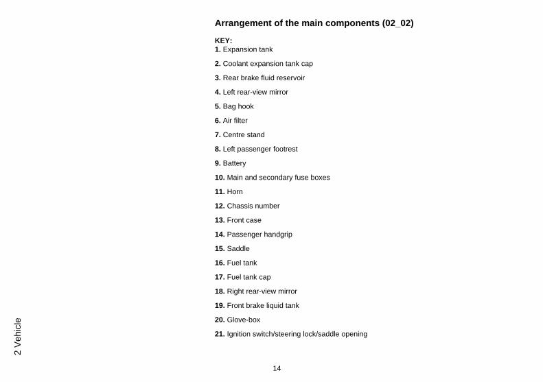
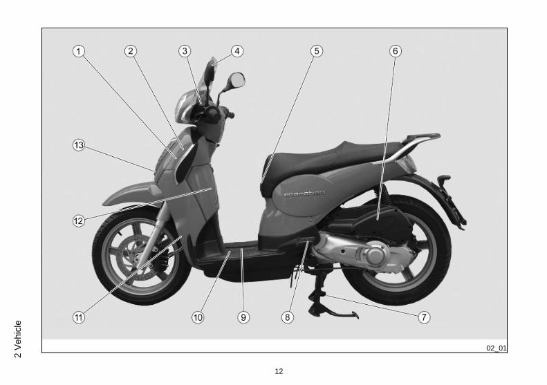
Arrangement of the main components (02_02)
KEY:1. Expansion tank
2. Coolant expansion tank cap
3. Rear brake fluid reservoir
4. Left rear-view mirror
5. Bag hook
6. Air filter
7. Centre stand
8. Left passenger footrest
9. Battery
10. Main and secondary fuse boxes
11. Horn
12. Chassis number
13. Front case
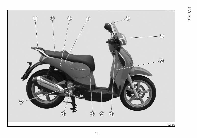
14. Passenger handgrip
15. Saddle
16. Fuel tank
17. Fuel tank cap
18. Right rear-view mirror
19. Front brake liquid tank
20. Glove-box
21. Ignition switch/steering lock/saddle opening
14
2 Ve
hicl
e
22. Battery compartment cover
23. Spark plug
24. Engine oil refill cap
25. Right passenger footrest
15
2 Vehicle
02_03
16
2 Ve
hicl
e
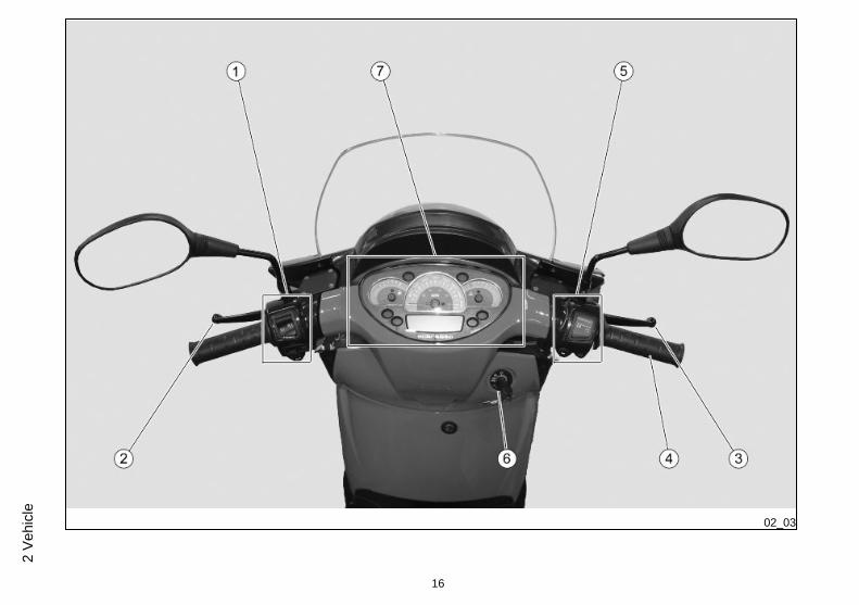
Dashboard (02_03)
KEY1. Electrical controls on the left-hand side of the handlebar
2. Rear brake lever
3. Front brake lever
4. Throttle grip
5. Electrical controls on the right-hand side of the handlebar
6. Ignition switch / steering lock (ON - OFF - LOCK) / saddle opening
7. Instruments and gauges
17
2 Vehicle
02_04
18
2 Ve
hicl
e
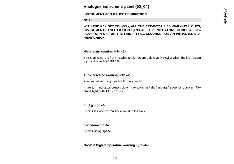
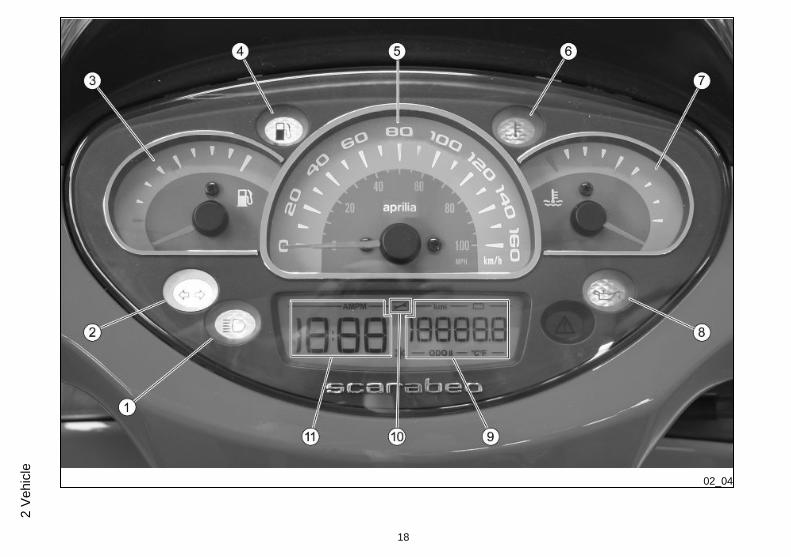
Analogue instrument panel (02_04)
INSTRUMENT AND GAUGE DESCRIPTION
NOTE
WITH THE KEY SET TO «ON», ALL THE PRE-INSTALLED WARNING LIGHTS,INSTRUMENT PANEL LIGHTING AND ALL THE INDICATORS IN DIGITAL DIS-PLAY TURN ON FOR THE FIRST THREE SECONDS FOR AN INITIAL INSTRU-MENT CHECK.
High beam warning light «1»
Turns on when the front headlamp high beam bulb is activated or when the high beamlight is flashed (PASSING).
Turn indicator warning light «2»
Flashes when in right or left turning mode.
If the turn indicator breaks down, the warning light flashing frequency doubles. Re-place light bulb if this occurs.
Fuel gauge «3»
Shows the approximate fuel level in the tank.
Speedometer «5»
Shows riding speed.
Coolant high temperature warning light «6»
19
2 Vehicle
Turns on when the coolant temperature indicator reaches very high values. Stop theengine at once and check the coolant level.
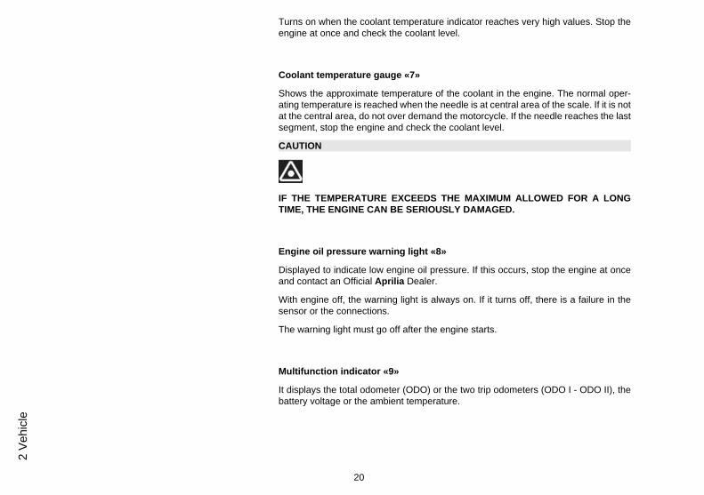
Coolant temperature gauge «7»
Shows the approximate temperature of the coolant in the engine. The normal oper-ating temperature is reached when the needle is at central area of the scale. If it is notat the central area, do not over demand the motorcycle. If the needle reaches the lastsegment, stop the engine and check the coolant level.
CAUTION
IF THE TEMPERATURE EXCEEDS THE MAXIMUM ALLOWED FOR A LONGTIME, THE ENGINE CAN BE SERIOUSLY DAMAGED.
Engine oil pressure warning light «8»
Displayed to indicate low engine oil pressure. If this occurs, stop the engine at onceand contact an Official Aprilia Dealer.
With engine off, the warning light is always on. If it turns off, there is a failure in thesensor or the connections.
The warning light must go off after the engine starts.
Multifunction indicator «9»
It displays the total odometer (ODO) or the two trip odometers (ODO I - ODO II), thebattery voltage or the ambient temperature.
20
2 Ve
hicl
e
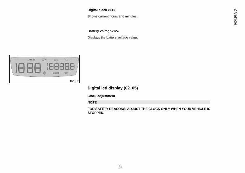
Digital clock «11»
Shows current hours and minutes.
Battery voltage«12»
Displays the battery voltage value.
02_05
Digital lcd display (02_05)
Clock adjustment
NOTE
FOR SAFETY REASONS, ADJUST THE CLOCK ONLY WHEN YOUR VEHICLE ISSTOPPED.
21
2 Vehicle
02_06
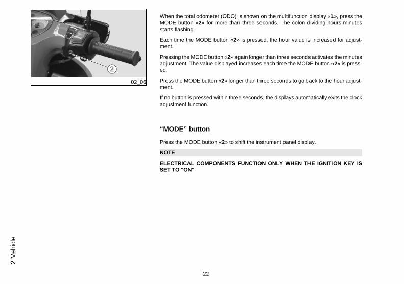
When the total odometer (ODO) is shown on the multifunction display «1», press theMODE button «2» for more than three seconds. The colon dividing hours-minutesstarts flashing.
Each time the MODE button «2» is pressed, the hour value is increased for adjust-ment.
Pressing the MODE button «2» again longer than three seconds activates the minutesadjustment. The value displayed increases each time the MODE button «2» is press-ed.
Press the MODE button «2» longer than three seconds to go back to the hour adjust-ment.
If no button is pressed within three seconds, the displays automatically exits the clockadjustment function.
“MODE” button
Press the MODE button «2» to shift the instrument panel display.
NOTE
ELECTRICAL COMPONENTS FUNCTION ONLY WHEN THE IGNITION KEY ISSET TO "ON"
22
2 Ve
hicl
e
02_07
02_08
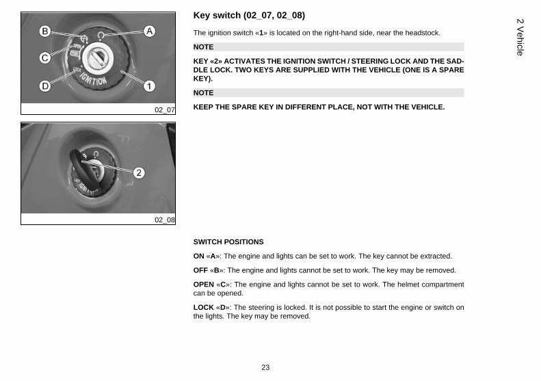
Key switch (02_07, 02_08)
The ignition switch «1» is located on the right-hand side, near the headstock.
NOTE
KEY «2» ACTIVATES THE IGNITION SWITCH / STEERING LOCK AND THE SAD-DLE LOCK. TWO KEYS ARE SUPPLIED WITH THE VEHICLE (ONE IS A SPAREKEY).
NOTE
KEEP THE SPARE KEY IN DIFFERENT PLACE, NOT WITH THE VEHICLE.
SWITCH POSITIONS
ON «A»: The engine and lights can be set to work. The key cannot be extracted.
OFF «B»: The engine and lights cannot be set to work. The key may be removed.
OPEN «C»: The engine and lights cannot be set to work. The helmet compartmentcan be opened.
LOCK «D»: The steering is locked. It is not possible to start the engine or switch onthe lights. The key may be removed.
23
2 Vehicle
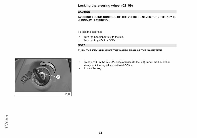
Locking the steering wheel (02_09)
CAUTION
AVOIDING LOSING CONTROL OF THE VEHICLE - NEVER TURN THE KEY TO«LOCK» WHILE RIDING.
To lock the steering:
• Turn the handlebar fully to the left.• Turn the key «2» to «OFF»
NOTE
TURN THE KEY AND MOVE THE HANDLEBAR AT THE SAME TIME.
02_09
• Press and turn the key «2» anticlockwise (to the left), move the handlebarslowly until the key «2» is set to «LOCK».
• Extract the key.
24
2 Ve
hicl
e
02_10
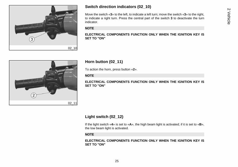
Switch direction indicators (02_10)
Move the switch «3» to the left, to indicate a left turn; move the switch «3» to the right,to indicate a right turn. Press the central part of the switch 3 to deactivate the turnindicator.
NOTE
ELECTRICAL COMPONENTS FUNCTION ONLY WHEN THE IGNITION KEY ISSET TO "ON"
02_11
Horn button (02_11)
To action the horn, press button «2».
NOTE
ELECTRICAL COMPONENTS FUNCTION ONLY WHEN THE IGNITION KEY ISSET TO "ON"
Light switch (02_12)
If the light switch «4» is set to «A», the high beam light is activated; if it is set to «B»,the low beam light is activated.
NOTE
ELECTRICAL COMPONENTS FUNCTION ONLY WHEN THE IGNITION KEY ISSET TO "ON"
25
2 Vehicle
02_12
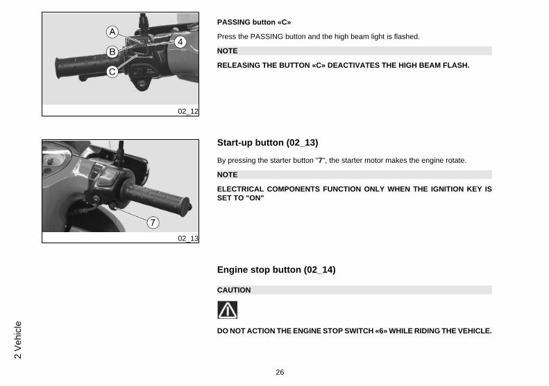
PASSING button «C»
Press the PASSING button and the high beam light is flashed.
NOTE
RELEASING THE BUTTON «C» DEACTIVATES THE HIGH BEAM FLASH.
02_13
Start-up button (02_13)
By pressing the starter button "7", the starter motor makes the engine rotate.
NOTE
ELECTRICAL COMPONENTS FUNCTION ONLY WHEN THE IGNITION KEY ISSET TO "ON"
Engine stop button (02_14)
CAUTION
DO NOT ACTION THE ENGINE STOP SWITCH «6» WHILE RIDING THE VEHICLE.
26
2 Ve
hicl
e
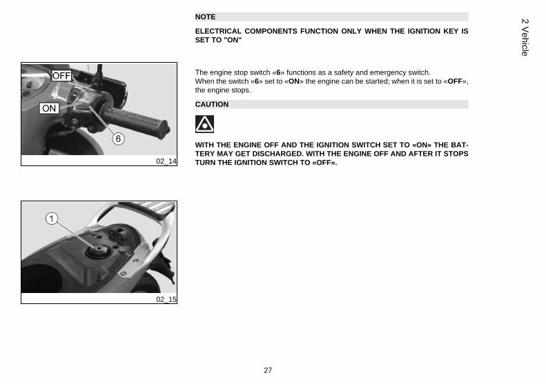
NOTE
ELECTRICAL COMPONENTS FUNCTION ONLY WHEN THE IGNITION KEY ISSET TO "ON"
02_14
The engine stop switch «6» functions as a safety and emergency switch.When the switch «6» set to «ON» the engine can be started; when it is set to «OFF»,the engine stops.
CAUTION
WITH THE ENGINE OFF AND THE IGNITION SWITCH SET TO «ON» THE BAT-TERY MAY GET DISCHARGED. WITH THE ENGINE OFF AND AFTER IT STOPSTURN THE IGNITION SWITCH TO «OFF».
02_15
27
2 Vehicle
02_16
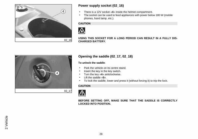
Power supply socket (02_16)
• There is a 12V socket «4» inside the helmet compartment.• The socket can be used to feed appliances with power below 180 W (mobile
phones, hand lamp, etc.).
CAUTION
USING THIS SOCKET FOR A LONG PERIOD CAN RESULT IN A FULLY DIS-CHARGED BATTERY.
02_17
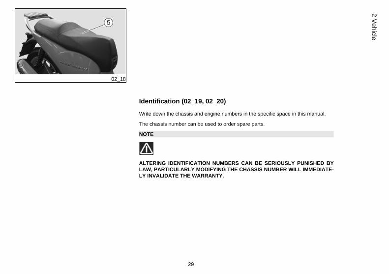
Opening the saddle (02_17, 02_18)
To unlock the saddle:
• Park the vehicle on its centre stand.• Insert the key in the key switch.• Turn the key «4» anticlockwise.• Lift the saddle «5».• To lock the saddle, lower and press it (without forcing it) to trip the lock.
CAUTION
BEFORE SETTING OFF, MAKE SURE THAT THE SADDLE IS CORRECTLYLOCKED INTO POSITION.
28
2 Ve
hicl
e
02_18
Identification (02_19, 02_20)
Write down the chassis and engine numbers in the specific space in this manual.
The chassis number can be used to order spare parts.
NOTE
ALTERING IDENTIFICATION NUMBERS CAN BE SERIOUSLY PUNISHED BYLAW, PARTICULARLY MODIFYING THE CHASSIS NUMBER WILL IMMEDIATE-LY INVALIDATE THE WARRANTY.
29
2 Vehicle
02_19
Chassis number
The chassis number is stamped on the chassis central bar. Remove the cover indi-cated to read it.
Chassis No.: ...............................................
02_20
Engine number
The engine number is stamped near the rear shock absorber lower support.
Engine No.: ...............................................
02_21
30
2 Ve
hicl
e
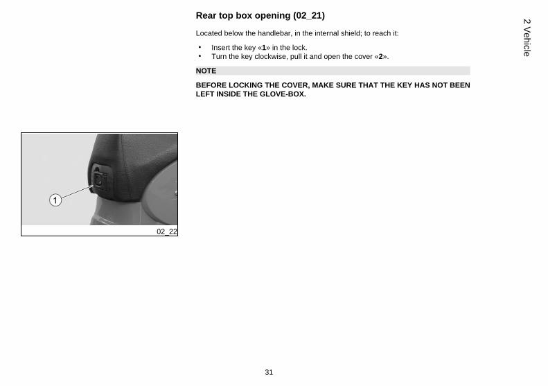
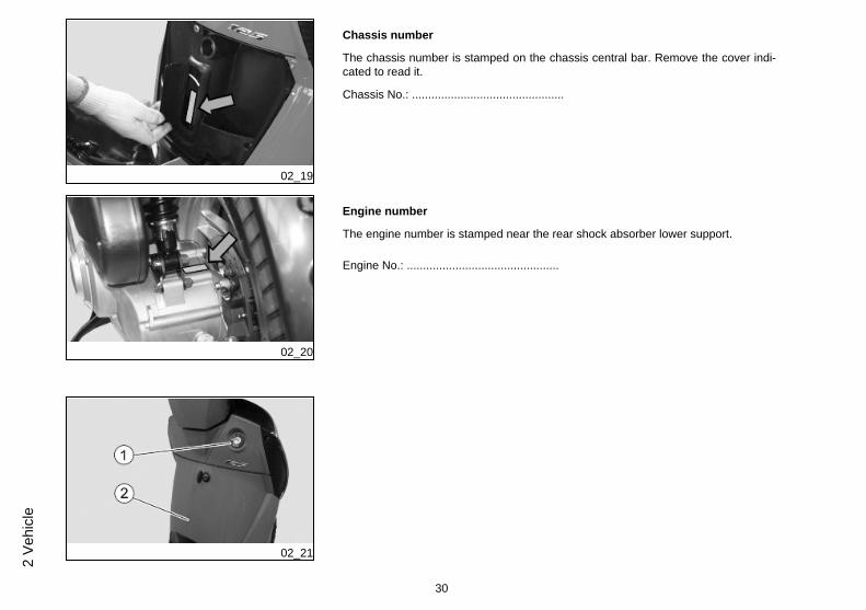
Rear top box opening (02_21)
Located below the handlebar, in the internal shield; to reach it:
• Insert the key «1» in the lock.• Turn the key clockwise, pull it and open the cover «2».
NOTE
BEFORE LOCKING THE COVER, MAKE SURE THAT THE KEY HAS NOT BEENLEFT INSIDE THE GLOVE-BOX.
02_22
31
2 Vehicle

32
2 Ve
hicl
e
SCARABEO 125 - 200Chap. 03
Use
33
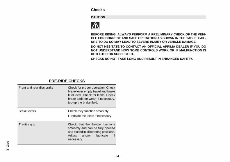
Checks
CAUTION
BEFORE RIDING, ALWAYS PERFORM A PRELIMINARY CHECK OF THE VEHI-CLE FOR CORRECT AND SAFE OPERATION AS SHOWN IN THE TABLE. FAIL-URE TO DO SO MAY LEAD TO SEVERE INJURY OR VEHICLE DAMAGE.DO NOT HESITATE TO CONTACT AN OFFICIAL APRILIA DEALER IF YOU DONOT UNDERSTAND HOW SOME CONTROLS WORK OR IF MALFUNCTION ISDETECTED OR SUSPECTED.CHECKS DO NOT TAKE LONG AND RESULT IN ENHANCED SAFETY.
PRE-RIDE CHECKSFront and rear disc brake Check for proper operation. Check
brake lever empty travel and brakefluid level. Check for leaks. Checkbrake pads for wear. If necessary,top-up the brake fluid.
Brake levers Check they function smoothly.Lubricate the joints if necessary.
Throttle grip Check that the throttle functionssmoothly and can be fully openedand closed in all steering positions.Adjust and/or lubricate ifnecessary.
34
3 U
se
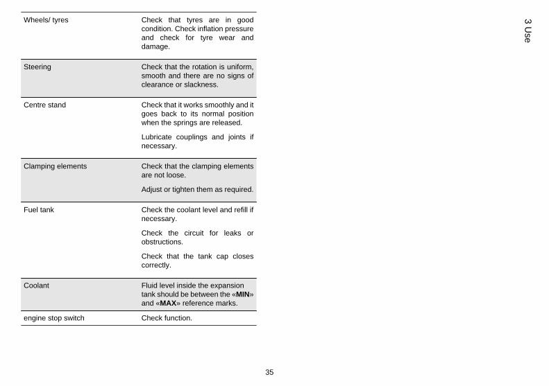
Wheels/ tyres Check that tyres are in goodcondition. Check inflation pressureand check for tyre wear anddamage.
Steering Check that the rotation is uniform,smooth and there are no signs ofclearance or slackness.
Centre stand Check that it works smoothly and itgoes back to its normal positionwhen the springs are released.
Lubricate couplings and joints ifnecessary.
Clamping elements Check that the clamping elementsare not loose.
Adjust or tighten them as required.
Fuel tank Check the coolant level and refill ifnecessary.
Check the circuit for leaks orobstructions.
Check that the tank cap closescorrectly.
Coolant Fluid level inside the expansiontank should be between the «MIN»and «MAX» reference marks.
engine stop switch Check function.
35
3 Use
03_01
03_02
03_03
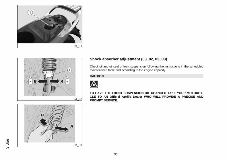
Shock absorber adjustment (03_02, 03_03)
Check oil and oil seal of front suspension following the instructions in the scheduledmaintenance table and according to the engine capacity.
CAUTION
TO HAVE THE FRONT SUSPENSION OIL CHANGED TAKE YOUR MOTORCY-CLE TO AN Official Aprilia Dealer WHO WILL PROVIDE A PRECISE ANDPROMPT SERVICE.
36
3 U
se
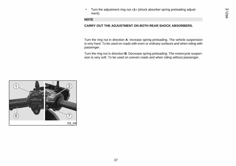
• Turn the adjustment ring nut «1» (shock absorber spring preloading adjust-ment).
NOTE
CARRY OUT THE ADJUSTMENT ON BOTH REAR SHOCK ABSORBERS.
Turn the ring nut in direction A: Increase spring preloading. The vehicle suspensionis very hard. To be used on roads with even or ordinary surfaces and when riding withpassenger.
Turn the ring nut in direction B: Decrease spring preloading. The motorcycle suspen-sion is very soft. To be used on uneven roads and when riding without passenger.
03_04
37
3 Use
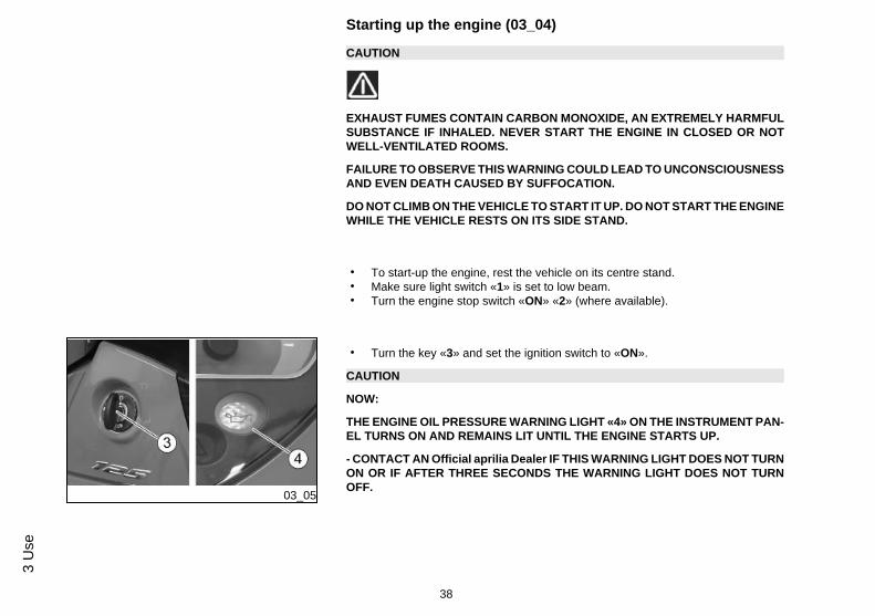
Starting up the engine (03_04)
CAUTION
EXHAUST FUMES CONTAIN CARBON MONOXIDE, AN EXTREMELY HARMFULSUBSTANCE IF INHALED. NEVER START THE ENGINE IN CLOSED OR NOTWELL-VENTILATED ROOMS.
FAILURE TO OBSERVE THIS WARNING COULD LEAD TO UNCONSCIOUSNESSAND EVEN DEATH CAUSED BY SUFFOCATION.
DO NOT CLIMB ON THE VEHICLE TO START IT UP. DO NOT START THE ENGINEWHILE THE VEHICLE RESTS ON ITS SIDE STAND.
• To start-up the engine, rest the vehicle on its centre stand.• Make sure light switch «1» is set to low beam.• Turn the engine stop switch «ON» «2» (where available).
03_05
• Turn the key «3» and set the ignition switch to «ON».
CAUTION
NOW:
THE ENGINE OIL PRESSURE WARNING LIGHT «4» ON THE INSTRUMENT PAN-EL TURNS ON AND REMAINS LIT UNTIL THE ENGINE STARTS UP.
- CONTACT AN Official aprilia Dealer IF THIS WARNING LIGHT DOES NOT TURNON OR IF AFTER THREE SECONDS THE WARNING LIGHT DOES NOT TURNOFF.
38
3 U
se
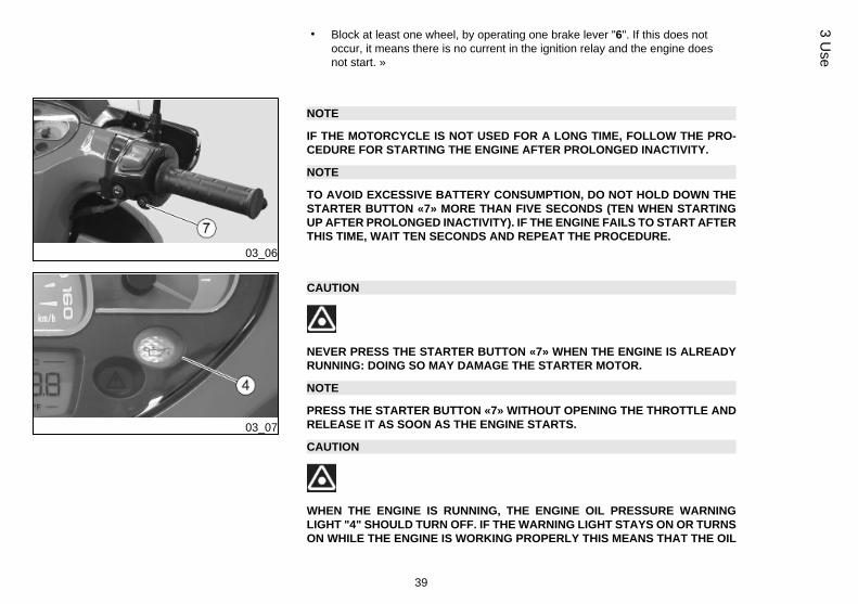
• Block at least one wheel, by operating one brake lever "6". If this does notoccur, it means there is no current in the ignition relay and the engine doesnot start. »
03_06
NOTE
IF THE MOTORCYCLE IS NOT USED FOR A LONG TIME, FOLLOW THE PRO-CEDURE FOR STARTING THE ENGINE AFTER PROLONGED INACTIVITY.
NOTE
TO AVOID EXCESSIVE BATTERY CONSUMPTION, DO NOT HOLD DOWN THESTARTER BUTTON «7» MORE THAN FIVE SECONDS (TEN WHEN STARTINGUP AFTER PROLONGED INACTIVITY). IF THE ENGINE FAILS TO START AFTERTHIS TIME, WAIT TEN SECONDS AND REPEAT THE PROCEDURE.
03_07
CAUTION
NEVER PRESS THE STARTER BUTTON «7» WHEN THE ENGINE IS ALREADYRUNNING: DOING SO MAY DAMAGE THE STARTER MOTOR.
NOTE
PRESS THE STARTER BUTTON «7» WITHOUT OPENING THE THROTTLE ANDRELEASE IT AS SOON AS THE ENGINE STARTS.
CAUTION
WHEN THE ENGINE IS RUNNING, THE ENGINE OIL PRESSURE WARNINGLIGHT "4" SHOULD TURN OFF. IF THE WARNING LIGHT STAYS ON OR TURNSON WHILE THE ENGINE IS WORKING PROPERLY THIS MEANS THAT THE OIL
39
3 Use
PRESSURE IN THE CIRCUIT IS NOT ENOUGH. SHOULD THIS OCCUR, STOPTHE ENGINE AT ONCE AND CONTACT AN aprilia Official Dealer. NEVER USETHE VEHICLE WITH LOW ENGINE OIL SO AS TO AVOID DAMAGING ENGINEPARTS.
03_08
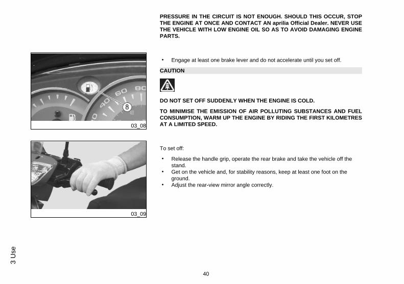
• Engage at least one brake lever and do not accelerate until you set off.
CAUTION
DO NOT SET OFF SUDDENLY WHEN THE ENGINE IS COLD.
TO MINIMISE THE EMISSION OF AIR POLLUTING SUBSTANCES AND FUELCONSUMPTION, WARM UP THE ENGINE BY RIDING THE FIRST KILOMETRESAT A LIMITED SPEED.
03_09
To set off:
• Release the handle grip, operate the rear brake and take the vehicle off thestand.
• Get on the vehicle and, for stability reasons, keep at least one foot on theground.
• Adjust the rear-view mirror angle correctly.
40
3 U
se
CAUTION
WITH THE VEHICLE AT A STANDSTILL, PRACTICE USING THE REAR-VIEWMIRRORS. THE MIRRORS ARE CONVEX, SO OBJECTS MAY SEEM FARTHERAWAY THAN THEY REALLY ARE. THESE MIRRORS OFFER A WIDE-ANGLEVIEW AND ONLY EXPERIENCE HELPS YOU JUDGE THE DISTANCE SEPARAT-ING YOU AND THE VEHICLE BEHIND.
03_10
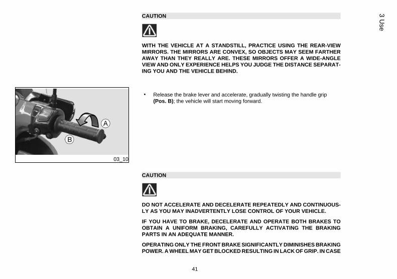
• Release the brake lever and accelerate, gradually twisting the handle grip(Pos. B); the vehicle will start moving forward.
CAUTION
DO NOT ACCELERATE AND DECELERATE REPEATEDLY AND CONTINUOUS-LY AS YOU MAY INADVERTENTLY LOSE CONTROL OF YOUR VEHICLE.
IF YOU HAVE TO BRAKE, DECELERATE AND OPERATE BOTH BRAKES TOOBTAIN A UNIFORM BRAKING, CAREFULLY ACTIVATING THE BRAKINGPARTS IN AN ADEQUATE MANNER.
OPERATING ONLY THE FRONT BRAKE SIGNIFICANTLY DIMINISHES BRAKINGPOWER. A WHEEL MAY GET BLOCKED RESULTING IN LACK OF GRIP. IN CASE
41
3 Use
OF STOP IN ASCENT, FULLY DECELERATE AND ONLY USE THE BRAKES TOKEEP THE VEHICLE STOPPED. USING THE ENGINE TO KEEP THE VEHICLESTOPPED MAY CAUSE THE VARIATOR TO OVERHEAT.
CAUTION
BEFORE GETTING INTO A BEND, REDUCE SPEED OR BRAKE; WHILE BEND-ING, RIDE AT THE SAME MODERATE AND CONSTANT SPEED OR SLIGHTLYACCELERATE; DO NOT BRAKE IN EXCESS: THERE IS HIGH RISK OF SKID-DING.
BRAKING CONTINUOUSLY WHILE GOING DOWNHILL MAY RESULT IN FRIC-TION GASKET OVERHEATING AND CONSEQUENTLY IN POOR BRAKING.TAKE ADVANTAGE OF THE ENGINE COMPRESSION USING THE BRAKES AL-TERNATIVELY. WHEN GOING DOWNHILL NEVER RIDE WITH THE ENGINE OFF.WHEN RIDING ON WET SURFACES OR WITH POOR GRIP (SNOW, ICE, MUD,ETC.) AT A MODERATE SPEED AVOIDING SUDDEN BRAKING OR MANOEU-VRES THAT MAY LEAD TO LACK OF GRIP AND CONSEQUENTLY TO FALLS.PAY ATTENTION TO OBSTACLES ON OR VARIATIONS IN THE ROAD SUR-FACE. UNEVEN ROADS, RUTS, DRAINS, TRAFFIC SIGNS PAINTED ON THEROADS, PIPEWORK METAL SHEETS MAY BECOME SLIPPERY WHEN ITRAINS. CROSS OVER THEM WITH EXTREME CAUTION, RIDE CAREFULLY ANDINCLINE THE MOTORCYCLE THE LEAST POSSIBLE.
CAUTION
ALWAYS SIGNAL CHANGES IN DIRECTION WITH THE APPROPRIATE DEVICESAND WELL IN ADVANCE, AVOID ABRUPT AND DANGEROUS MANOEUVRES.TURN OFF THE DEVICES IMMEDIATELY AFTER THE CHANGE IN DIRECTION.WHEN OVERTAKING OR BEING OVERTAKEN BY OTHER VEHICLES RIDE WITHEXTREME CAUTION. WHEN IT RAINS, SPRAY CAUSED BY LARGE VEHICLESREDUCES VISIBILITY; AIR SHIFTS MAY CAUSE LOSS OF CONTROL ON YOURMOTORCYCLE.
42
3 U
se
03_11
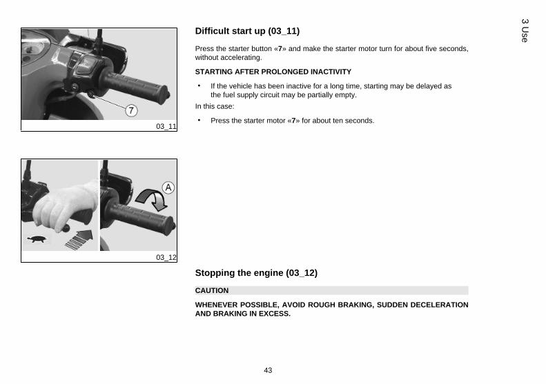
Difficult start up (03_11)
Press the starter button «7» and make the starter motor turn for about five seconds,without accelerating.
STARTING AFTER PROLONGED INACTIVITY
• If the vehicle has been inactive for a long time, starting may be delayed asthe fuel supply circuit may be partially empty.
In this case:
• Press the starter motor «7» for about ten seconds.
03_12
Stopping the engine (03_12)
CAUTION
WHENEVER POSSIBLE, AVOID ROUGH BRAKING, SUDDEN DECELERATIONAND BRAKING IN EXCESS.
43
3 Use
03_13
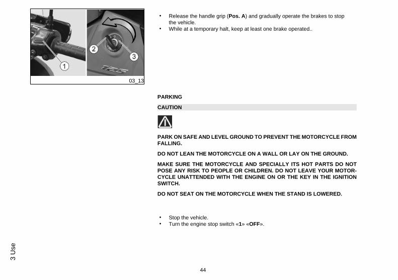
• Release the handle grip (Pos. A) and gradually operate the brakes to stopthe vehicle.
• While at a temporary halt, keep at least one brake operated..
PARKING
CAUTION
PARK ON SAFE AND LEVEL GROUND TO PREVENT THE MOTORCYCLE FROMFALLING.
DO NOT LEAN THE MOTORCYCLE ON A WALL OR LAY ON THE GROUND.
MAKE SURE THE MOTORCYCLE AND SPECIALLY ITS HOT PARTS DO NOTPOSE ANY RISK TO PEOPLE OR CHILDREN. DO NOT LEAVE YOUR MOTOR-CYCLE UNATTENDED WITH THE ENGINE ON OR THE KEY IN THE IGNITIONSWITCH.
DO NOT SEAT ON THE MOTORCYCLE WHEN THE STAND IS LOWERED.
• Stop the vehicle.• Turn the engine stop switch «1» «OFF».
44
3 U
se
CAUTION
WITH ENGINE OFF AND THE IGNITION SWITCH SET TO «ON» THE BATTERYMAY GET DISCHARGED.
• Turn the key «2» and set the ignition switch «3» to «OFF» .• Rest the vehicle on its stand.
CAUTION
DO NOT LEAVE THE KEY INSERTED IN THE IGNITION SWITCH.
NOTE
WITH THE ENGINE OFF, IT IS NOT NECESSARY TO CLOSE THE FUEL VALVE,FOR IT HAS AN AUTOMATIC SEALING SYSTEM.
• Lock the steering and take out the key «2».
Catalytic silencer
CAUTION
DO NOT TAMPER THE NOISE CONTROL SYSTEM.
Vehicle owners are warned that the law may prohibit the following:
45
3 Use
- the removal of any device or element belonging to a new vehicle or any other actionby anyone leading to render it non-operating, if not for maintenance, repair or re-placement reasons, in order to control noise emission before the sale or delivery ofthe vehicle to the ultimate buyer or while it is used; and
- using the vehicle after that device or part has been removed or made non-operating.
Check the muffler/exhaust silencer and the silencer pipes, make sure there are nosigns of rust or holes and that the exhaust system works properly. If exhaust noiseincreases, take your vehicle at once to an Official Aprilia Dealer.
03_14
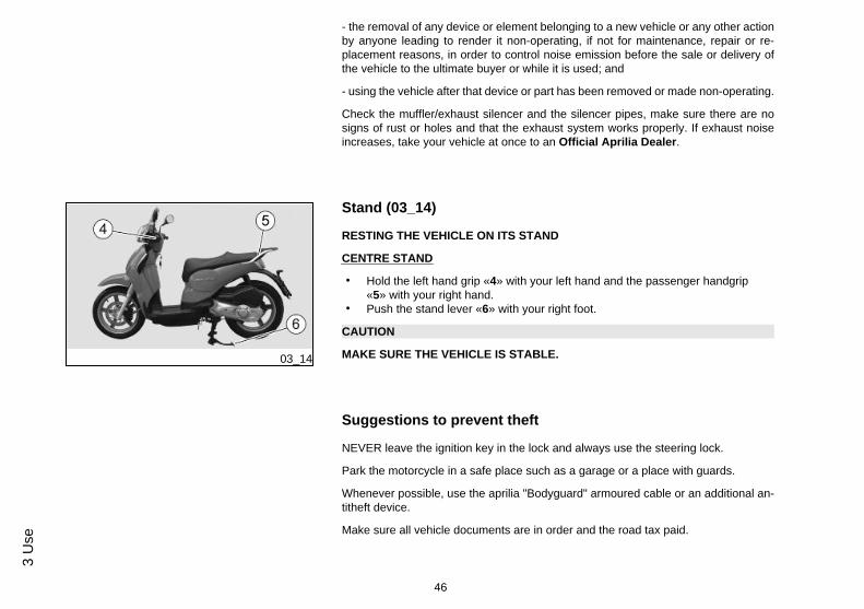
Stand (03_14)
RESTING THE VEHICLE ON ITS STAND
CENTRE STAND
• Hold the left hand grip «4» with your left hand and the passenger handgrip«5» with your right hand.
• Push the stand lever «6» with your right foot.
CAUTION
MAKE SURE THE VEHICLE IS STABLE.
Suggestions to prevent theft
NEVER leave the ignition key in the lock and always use the steering lock.
Park the motorcycle in a safe place such as a garage or a place with guards.
Whenever possible, use the aprilia "Bodyguard" armoured cable or an additional an-titheft device.
Make sure all vehicle documents are in order and the road tax paid.
46
3 U
se
Write down your personal details and telephone number on this page to help identi-fying the owner in case of vehicle retrieval after a theft.
LAST NAME: ....................
NAME: ..........................
ADDRESS: ....................
TELEPHONE NO.: ............
IMPORTANT: In many cases, stolen vehicles can be identified through data indicatedin the use and maintenance booklet.
03_15
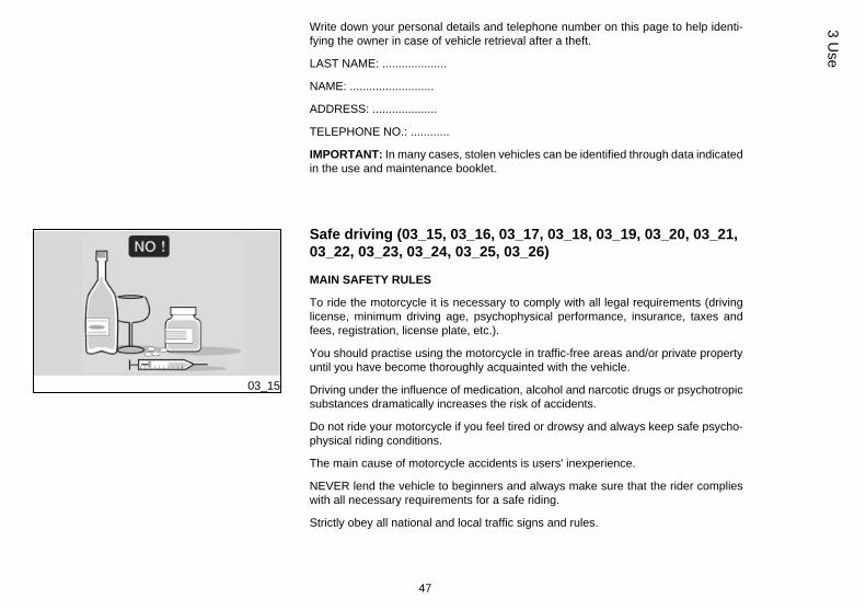
Safe driving (03_15, 03_16, 03_17, 03_18, 03_19, 03_20, 03_21,03_22, 03_23, 03_24, 03_25, 03_26)
MAIN SAFETY RULES
To ride the motorcycle it is necessary to comply with all legal requirements (drivinglicense, minimum driving age, psychophysical performance, insurance, taxes andfees, registration, license plate, etc.).
You should practise using the motorcycle in traffic-free areas and/or private propertyuntil you have become thoroughly acquainted with the vehicle.
Driving under the influence of medication, alcohol and narcotic drugs or psychotropicsubstances dramatically increases the risk of accidents.
Do not ride your motorcycle if you feel tired or drowsy and always keep safe psycho-physical riding conditions.
The main cause of motorcycle accidents is users' inexperience.
NEVER lend the vehicle to beginners and always make sure that the rider complieswith all necessary requirements for a safe riding.
Strictly obey all national and local traffic signs and rules.
47
3 Use
03_16
03_17
Avoid any abrupt and dangerous swerves for your own as well as others' safety (forexample: rearing up on the back wheel, riding over the speed limit, etc.). Besides,always assess and bear in mind the road surface conditions, visibility, etc.
Do not knock obstacles that can damage the motorcycle or cause loss of control.
Do not ride on the course of the vehicle in front just to improve your own speed.
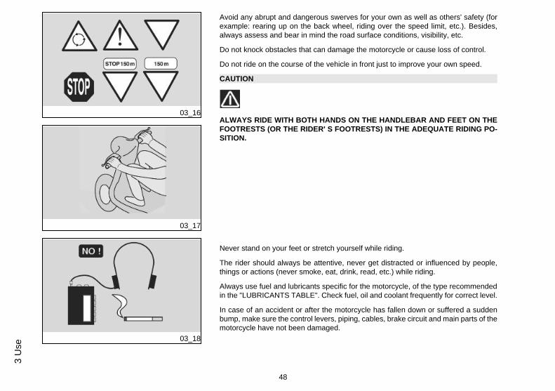
CAUTION
ALWAYS RIDE WITH BOTH HANDS ON THE HANDLEBAR AND FEET ON THEFOOTRESTS (OR THE RIDER' S FOOTRESTS) IN THE ADEQUATE RIDING PO-SITION.
03_18
Never stand on your feet or stretch yourself while riding.
The rider should always be attentive, never get distracted or influenced by people,things or actions (never smoke, eat, drink, read, etc.) while riding.
Always use fuel and lubricants specific for the motorcycle, of the type recommendedin the "LUBRICANTS TABLE". Check fuel, oil and coolant frequently for correct level.
In case of an accident or after the motorcycle has fallen down or suffered a suddenbump, make sure the control levers, piping, cables, brake circuit and main parts of themotorcycle have not been damaged.
48
3 U
se
03_19
03_20
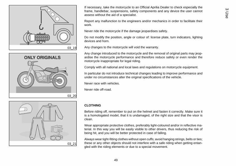
If necessary, take the motorcycle to an Official Aprilia Dealer to check especially theframe, handlebar, suspensions, safety components and any device the user cannotassess without the aid of a specialist.
Report any malfunction to the engineers and/or mechanics in order to facilitate theirwork.
Never ride the motorcycle if the damage jeopardises safety.
Do not modify the position, angle or colour of: license plate, turn indicators, lightingdevices and horn.
Any changes to the motorcycle will void the warranty.
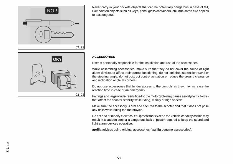
Any change introduced to the motorcycle and the removal of original parts may jeop-ardise the motorcycle performance and therefore reduce safety or even render themotorcycle inappropriate for legal riding.
Comply with all national and local laws and regulations on motorcycle equipment.
In particular do not introduce technical changes leading to improve performance andunder no circumstances alter the original specifications of the vehicle.
Never race with vehicles.
Never ride off-road.
03_21
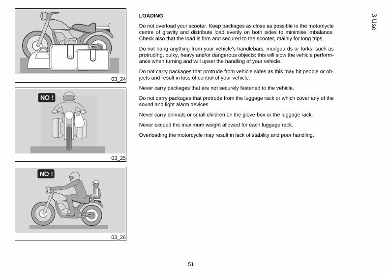
CLOTHING
Before riding off, remember to put on the helmet and fasten it correctly. Make sure itis a homologated model, that it is undamaged, of the right size and that the visor isclean.
Wear appropriate protective clothes, preferably light-coloured and/or in reflective ma-terial. In this way you will be easily visible to other drivers, thus reducing the risk ofbeing hit, and you will be better protected in case of falling.
Always wear tight-fitting clothes without open cuffs; avoid hanging strings, belts or ties;these or any other objects should not interfere with a safe riding when getting entan-gled with the riding elements or due to a special movement.
49
3 Use
03_22
Never carry in your pockets objects that can be potentially dangerous in case of fall,like: pointed objects such as keys, pens, glass containers, etc. (the same rule appliesto passengers).
03_23
ACCESSORIES
User is personally responsible for the installation and use of the accessories.
While assembling accessories, make sure that they do not cover the sound or lightalarm devices or affect their correct functioning, do not limit the suspension travel orthe steering angle, do not obstruct control actuation or reduce the ground clearanceand inclination angle at corners.
Do not use accessories that hinder access to the controls as they may increase thereaction time in case of an emergency.
Fairings and large windscreens fitted to the motorcycle may cause aerodynamic forcesthat affect the scooter stability while riding, mainly at high speeds.
Make sure the accessory is firm and secured to the scooter and that it does not poseany risks while riding the motorcycle.
Do not add or modify electrical equipment that exceed the vehicle capacity as this mayresult in a sudden stop or a dangerous lack of power required to keep the sound andlight alarm devices operative.
aprilia advises using original accessories (aprilia genuine accessories).
50
3 U
se
03_24
03_25
03_26
LOADING
Do not overload your scooter. Keep packages as close as possible to the motorcyclecentre of gravity and distribute load evenly on both sides to minimise imbalance.Check also that the load is firm and secured to the scooter, mainly for long trips.
Do not hang anything from your vehicle's handlebars, mudguards or forks, such asprotruding, bulky, heavy and/or dangerous objects: this will slow the vehicle perform-ance when turning and will upset the handling of your vehicle.
Do not carry packages that protrude from vehicle sides as this may hit people or ob-jects and result in loss of control of your vehicle.
Never carry packages that are not securely fastened to the vehicle.
Do not carry packages that protrude from the luggage rack or which cover any of thesound and light alarm devices.
Never carry animals or small children on the glove-box or the luggage rack.
Never exceed the maximum weight allowed for each luggage rack.
Overloading the motorcycle may result in lack of stability and poor handling.
51
3 Use

52
3 U
se
SCARABEO 125 - 200Chap. 04
Maintenance
53
Engine oil level (04_01)
Check engine oil level frequently according to the indications in the scheduled main-tenance table.
CAUTION
HANDLING OIL FOR PROLONGED PERIODS AND ON A REGULAR BASIS CANCAUSE SERIOUS SKIN DAMAGE.
WASH YOUR HANDS CAREFULLY AFTER HANDLING OIL.
WHEN CARRYING OUT MAINTENANCE OPERATIONS, IT IS ADVISABLE TOWEAR LATEX GLOVES.
KEEP OUT OF THE REACH OF CHILDREN.
DO NOT DISPOSE OF OIL INTO THE ENVIRONMENT.
CAUTION
PROCEED WITH CAUTION.
DO NOT SPILL OIL.
BE CAREFUL NOT TO DIRTY COMPONENTS, THE WORKING OR SURROUND-ING AREA.
THOROUGHLY WASH OUT ANY OIL TRACE.
IN THE EVENT OF OIL LEAKS OR MALFUNCTIONING, TAKE YOUR VEHICLETO AN Official aprilia Dealer.
NOTE
USE OIL WITH THE SPECIFICATIONS DETAILED IN THE RECOMMENDEDPRODUCTS TABLE.
54
4 M
aint
enan
ce
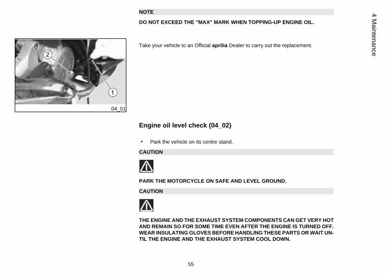
NOTE
DO NOT EXCEED THE "MAX" MARK WHEN TOPPING-UP ENGINE OIL.
04_01
Take your vehicle to an Official aprilia Dealer to carry out the replacement.
Engine oil level check (04_02)
• Park the vehicle on its centre stand.
CAUTION
PARK THE MOTORCYCLE ON SAFE AND LEVEL GROUND.
CAUTION
THE ENGINE AND THE EXHAUST SYSTEM COMPONENTS CAN GET VERY HOTAND REMAIN SO FOR SOME TIME EVEN AFTER THE ENGINE IS TURNED OFF.WEAR INSULATING GLOVES BEFORE HANDLING THESE PARTS OR WAIT UN-TIL THE ENGINE AND THE EXHAUST SYSTEM COOL DOWN.
55
4 Maintenance
• Stop the engine and let it cool down. This will allow the oil to settle into thecrankcase and cool down.
NOTE
FAILURE TO FOLLOW THESE OPERATIONS MAY RESULT IN AN INCORRECTREADING OF THE ENGINE OIL LEVEL.
04_02
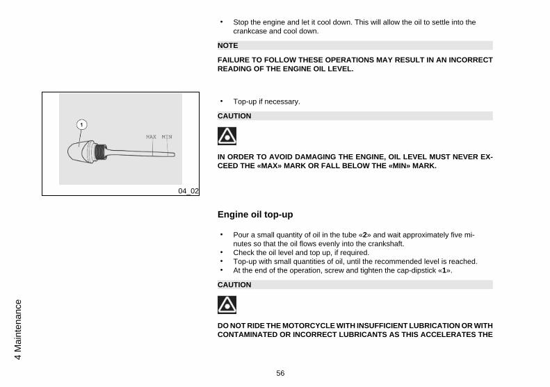
• Top-up if necessary.
CAUTION
IN ORDER TO AVOID DAMAGING THE ENGINE, OIL LEVEL MUST NEVER EX-CEED THE «MAX» MARK OR FALL BELOW THE «MIN» MARK.
Engine oil top-up
• Pour a small quantity of oil in the tube «2» and wait approximately five mi-nutes so that the oil flows evenly into the crankshaft.
• Check the oil level and top up, if required.• Top-up with small quantities of oil, until the recommended level is reached.• At the end of the operation, screw and tighten the cap-dipstick «1».
CAUTION
DO NOT RIDE THE MOTORCYCLE WITH INSUFFICIENT LUBRICATION OR WITHCONTAMINATED OR INCORRECT LUBRICANTS AS THIS ACCELERATES THE
56
4 M
aint
enan
ce
WEAR AND TEAR OF THE MOVING PARTS AND CAN CAUSE IRRETRIEVABLEDAMAGE.
04_03
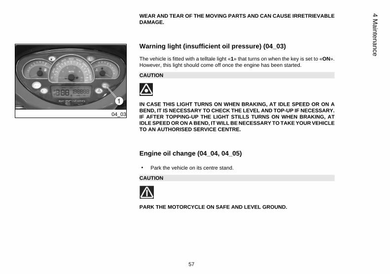
Warning light (insufficient oil pressure) (04_03)
The vehicle is fitted with a telltale light «1» that turns on when the key is set to «ON».However, this light should come off once the engine has been started.
CAUTION
IN CASE THIS LIGHT TURNS ON WHEN BRAKING, AT IDLE SPEED OR ON ABEND, IT IS NECESSARY TO CHECK THE LEVEL AND TOP-UP IF NECESSARY.IF AFTER TOPPING-UP THE LIGHT STILLS TURNS ON WHEN BRAKING, ATIDLE SPEED OR ON A BEND, IT WILL BE NECESSARY TO TAKE YOUR VEHICLETO AN AUTHORISED SERVICE CENTRE.
Engine oil change (04_04, 04_05)
• Park the vehicle on its centre stand.
CAUTION
PARK THE MOTORCYCLE ON SAFE AND LEVEL GROUND.
57
4 Maintenance
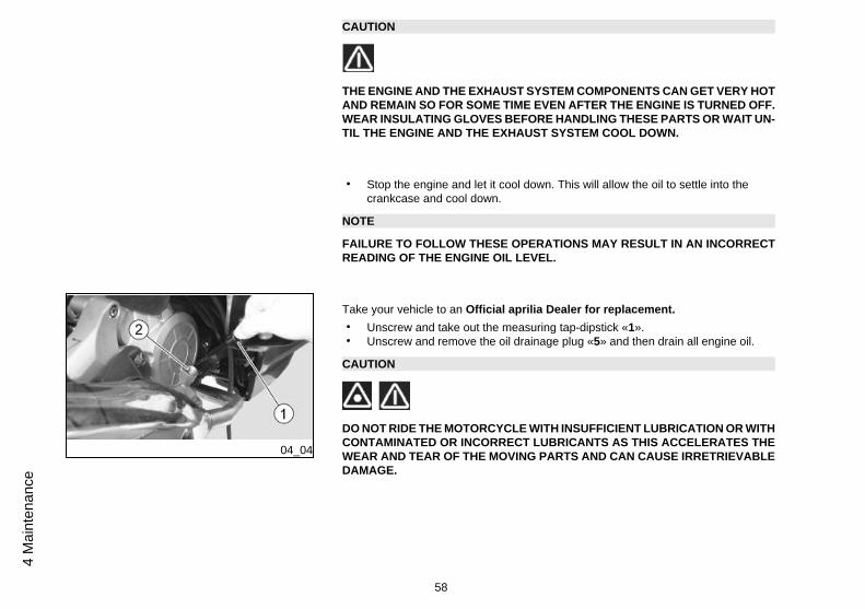
CAUTION
THE ENGINE AND THE EXHAUST SYSTEM COMPONENTS CAN GET VERY HOTAND REMAIN SO FOR SOME TIME EVEN AFTER THE ENGINE IS TURNED OFF.WEAR INSULATING GLOVES BEFORE HANDLING THESE PARTS OR WAIT UN-TIL THE ENGINE AND THE EXHAUST SYSTEM COOL DOWN.
• Stop the engine and let it cool down. This will allow the oil to settle into thecrankcase and cool down.
NOTE
FAILURE TO FOLLOW THESE OPERATIONS MAY RESULT IN AN INCORRECTREADING OF THE ENGINE OIL LEVEL.
04_04
Take your vehicle to an Official aprilia Dealer for replacement.• Unscrew and take out the measuring tap-dipstick «1».• Unscrew and remove the oil drainage plug «5» and then drain all engine oil.
CAUTION
DO NOT RIDE THE MOTORCYCLE WITH INSUFFICIENT LUBRICATION OR WITHCONTAMINATED OR INCORRECT LUBRICANTS AS THIS ACCELERATES THEWEAR AND TEAR OF THE MOVING PARTS AND CAN CAUSE IRRETRIEVABLEDAMAGE.
58
4 M
aint
enan
ce
04_05
CAUTION
AS USED OIL HAS SUBSTANCES HARMFUL TO THE ENVIRONMENT, TAKEYOUR SCOOTER TO AN OFFICIAL APRILIA DEALER TO HAVE THE OILCHANGED. THESE CENTRES CAN CARRY OUT ENVIRONMENTALLY-FRIEND-LY DISPOSAL OF USED OIL IN COMPLIANCE WITH REGULATIONS IN FORCE.
04_06
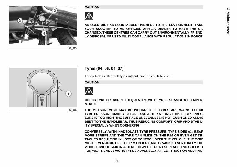
Tyres (04_06, 04_07)
This vehicle is fitted with tyres without inner tubes (Tubeless).
CAUTION
CHECK TYRE PRESSURE FREQUENTLY, WITH TYRES AT AMBIENT TEMPER-ATURE.
THE MEASUREMENT MAY BE INCORRECT IF TYRES ARE WARM. CHECKTYRE PRESSURE MAINLY BEFORE AND AFTER A LONG TRIP. IF TYRE PRES-SURE IS TOO HIGH, THE SURFACE UNEVENNESS IS NOT CUSHIONED AND ISSENT TO THE HANDLEBAR, THUS REDUCING COMFORT, GRIP AND STABIL-ITY SPECIALLY WHEN CORNERING.
CONVERSELY, WITH INADEQUATE TYRE PRESSURE, TYRE SIDES «1» BEARMORE STRESS AND THE TYRE CAN SLIDE ON THE RIM OR EVEN GET DE-TACHED RESULTING IN LOSS OF CONTROL OVER THE VEHICLE. THE TYREMIGHT EVEN JUMP OFF THE RIM UNDER HARD BRAKING. EVENTUALLY THEVEHICLE MIGHT SKID IN A BEND. INSPECT TREAD SURFACE AND CHECK ITFOR WEAR. BADLY WORN TYRES ADVERSELY AFFECT TRACTION AND HAN-
59
4 Maintenance
04_07
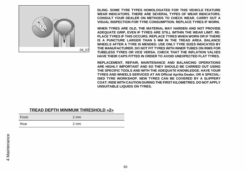
DLING. SOME TYRE TYPES HOMOLOGATED FOR THIS VEHICLE FEATUREWEAR INDICATORS. THERE ARE SEVERAL TYPES OF WEAR INDICATORS.CONSULT YOUR DEALER ON METHODS TO CHECK WEAR. CARRY OUT AVISUAL INSPECTION FOR TYRE CONSUMPTION. REPLACE TYRES IF WORN.
WHEN TYRES ARE OLD, THE MATERIAL MAY HARDEN AND NOT PROVIDEADEQUATE GRIP, EVEN IF TYRES ARE STILL WITHIN THE WEAR LIMIT. RE-PLACE TYRES IF THIS OCCURS. REPLACE TYRES WHEN WORN OR IF THEREIS A PUNCTURE LARGER THAN 5 MM IN THE TREAD AREA. BALANCEWHEELS AFTER A TYRE IS MENDED. USE ONLY TYRE SIZES INDICATED BYTHE MANUFACTURER. DO NOT FIT TYRES WITH INNER TUBES ON RIMS FORTUBELESS TYRES OR VICE VERSA. CHECK THAT THE INFLATION VALVESHAVE THEIR CAPS FITTED IN ORDER TO AVOID UNEXPECTED FLAT TYRES.
REPLACEMENT, REPAIR, MAINTENANCE AND BALANCING OPERATIONSARE HIGHLY IMPORTANT AND SO THEY SHOULD BE CARRIED OUT USINGTHE SPECIFIC TOOLS AND WITH THE ADEQUATE KNOWLEDGE. HAVE YOURTYRES AND WHEELS SERVICED AT AN Official Aprilia Dealer, OR A SPECIAL-ISED TYRE WORKSHOP. NEW TYRES CAN BE COVERED BY A SLIPPERYCOAT: RIDE WITH CAUTION DURING THE FIRST KILOMETRES. DO NOT APPLYUNSUITABLE LIQUIDS ON TYRES.
TREAD DEPTH MINIMUM THRESHOLD «2»Front: 2 mm
Rear 2 mm
60
4 M
aint
enan
ce
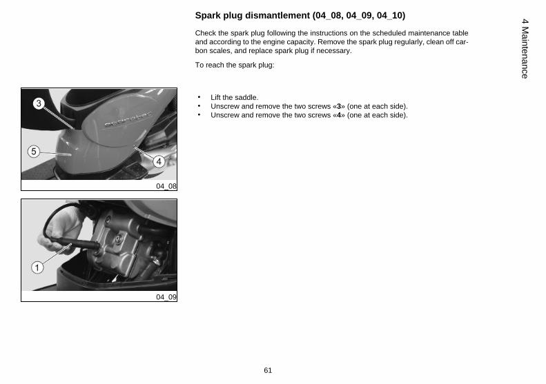
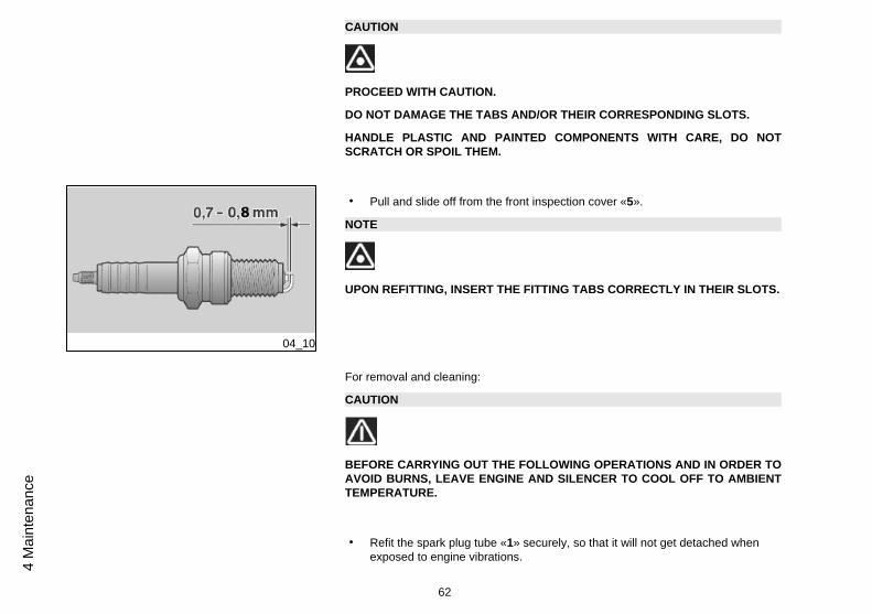
Spark plug dismantlement (04_08, 04_09, 04_10)
Check the spark plug following the instructions on the scheduled maintenance tableand according to the engine capacity. Remove the spark plug regularly, clean off car-bon scales, and replace spark plug if necessary.
To reach the spark plug:
04_08
04_09
• Lift the saddle.• Unscrew and remove the two screws «3» (one at each side).• Unscrew and remove the two screws «4» (one at each side).
61
4 Maintenance
CAUTION
PROCEED WITH CAUTION.
DO NOT DAMAGE THE TABS AND/OR THEIR CORRESPONDING SLOTS.
HANDLE PLASTIC AND PAINTED COMPONENTS WITH CARE, DO NOTSCRATCH OR SPOIL THEM.
04_10
• Pull and slide off from the front inspection cover «5».
NOTE
UPON REFITTING, INSERT THE FITTING TABS CORRECTLY IN THEIR SLOTS.
For removal and cleaning:
CAUTION
BEFORE CARRYING OUT THE FOLLOWING OPERATIONS AND IN ORDER TOAVOID BURNS, LEAVE ENGINE AND SILENCER TO COOL OFF TO AMBIENTTEMPERATURE.
• Refit the spark plug tube «1» securely, so that it will not get detached whenexposed to engine vibrations.
62
4 M
aint
enan
ce
• Refit the central inspection cover «5».
04_11
04_12
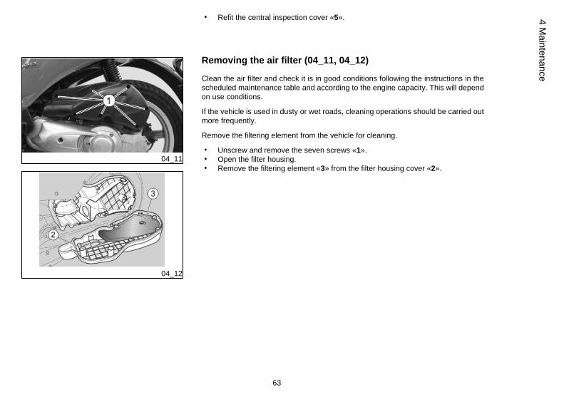
Removing the air filter (04_11, 04_12)
Clean the air filter and check it is in good conditions following the instructions in thescheduled maintenance table and according to the engine capacity. This will dependon use conditions.
If the vehicle is used in dusty or wet roads, cleaning operations should be carried outmore frequently.
Remove the filtering element from the vehicle for cleaning.
• Unscrew and remove the seven screws «1».• Open the filter housing.• Remove the filtering element «3» from the filter housing cover «2».
63
4 Maintenance
04_13
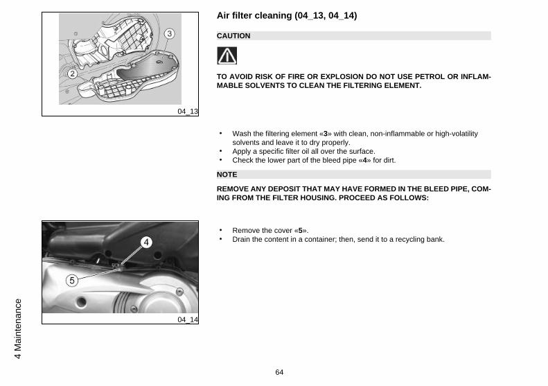
Air filter cleaning (04_13, 04_14)
CAUTION
TO AVOID RISK OF FIRE OR EXPLOSION DO NOT USE PETROL OR INFLAM-MABLE SOLVENTS TO CLEAN THE FILTERING ELEMENT.
• Wash the filtering element «3» with clean, non-inflammable or high-volatilitysolvents and leave it to dry properly.
• Apply a specific filter oil all over the surface.• Check the lower part of the bleed pipe «4» for dirt.
NOTE
REMOVE ANY DEPOSIT THAT MAY HAVE FORMED IN THE BLEED PIPE, COM-ING FROM THE FILTER HOUSING. PROCEED AS FOLLOWS:
04_14
• Remove the cover «5».• Drain the content in a container; then, send it to a recycling bank.
64
4 M
aint
enan
ce
Cooling fluid level (04_15, 04_16, 04_17, 04_18)
CAUTION
DO NOT USE YOUR MOTORCYCLE IF THE COOLANT LEVEL IS BELOW THEMINIMUM LEVEL MARKED "MIN".
Check the coolant level following the instructions in the scheduled maintenance tableand according to the engine capacity.
CAUTION
COOLANT IS TOXIC IF INGESTED; CONTACT WITH YOUR EYES OR SKIN MAYCAUSE IRRITATION. IF THE FLUID GETS IN CONTACT WITH THE EYES ORSKIN, RINSE REPEATEDLY WITH PLENTY OF WATER AND SEEK MEDICALADVICE. IF SWALLOWED, INDUCE VOMITING, RINSE MOUTH AND THROATWITH PLENTY OF WATER AND SEEK MEDICAL ADVICE IMMEDIATELY.
CAUTION
DO NOT DISPOSE OF THE FLUID INTO THE ENVIRONMENT.
CAUTION
KEEP OUT OF THE REACH OF CHILDREN.
65
4 Maintenance
CAUTION
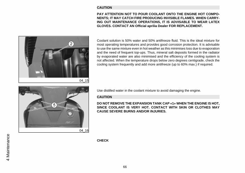
PAY ATTENTION NOT TO POUR COOLANT ONTO THE ENGINE HOT COMPO-NENTS; IT MAY CATCH FIRE PRODUCING INVISIBLE FLAMES. WHEN CARRY-ING OUT MAINTENANCE OPERATIONS, IT IS ADVISABLE TO WEAR LATEXGLOVES. CONTACT AN Official aprilia Dealer FOR REPLACEMENT.
04_15
Coolant solution is 50% water and 50% antifreeze fluid. This is the ideal mixture formost operating temperatures and provides good corrosion protection. It is advisableto use the same mixture even in hot weather as this minimises loss due to evaporationand the need of frequent top-ups. Thus, mineral salt deposits formed in the radiatorby evaporated water are also minimised and the efficiency of the cooling system isnot affected. When the temperature drops below zero degrees centigrade, check thecooling system frequently and add more antifreeze (up to 60% max.) if required.
04_16
Use distilled water in the coolant mixture to avoid damaging the engine.
CAUTION
DO NOT REMOVE THE EXPANSION TANK CAP «1» WHEN THE ENGINE IS HOT,SINCE COOLANT IS VERY HOT. CONTACT WITH SKIN OR CLOTHES MAYCAUSE SEVERE BURNS AND/OR INJURIES.
CHECK
66
4 M
aint
enan
ce
CAUTION
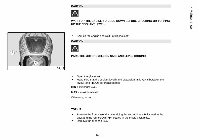
WAIT FOR THE ENGINE TO COOL DOWN BEFORE CHECKING OR TOPPING-UP THE COOLANT LEVEL.
04_17
• Shut off the engine and wait until it cools off.
CAUTION
PARK THE MOTORCYCLE ON SAFE AND LEVEL GROUND.
• Open the glove-box.• Make sure that the coolant level in the expansion tank «2» is between the
«MIN» and «MAX» reference marks.MIN = minimum level.
MAX = maximum level.
Otherwise, top-up.
TOP-UP
• Remove the front case «3» by undoing the two screws «4» located at theback and the four screws «5» located in the shield back plate.
• Remove the filler cap «1».
67
4 Maintenance
CAUTION
PROCEED WITH CAUTION.
DO NOT DAMAGE THE TABS AND/OR THEIR CORRESPONDING SLOTS.
HANDLE PLASTIC AND PAINTED COMPONENTS WITH CARE, DO NOTSCRATCH OR SPOIL THEM.
NOTE
UPON REFITTING, INSERT THE FITTING TABS CORRECTLY IN THEIR SLOTS.
CAUTION
COOLANT IS TOXIC IF INGESTED; CONTACT WITH YOUR EYES OR SKIN MAYCAUSE IRRITATION. DO NOT INTRODUCE YOUR FINGERS OR ANY OTHEROBJECT TO CHECK IF THERE IS COOLANT OR NOT.
CAUTION
WHEN TOPPING-UP, DO NOT EXCEED THE «MAX» LEVEL OR THE FLUID WILLFLOW OUT WHEN THE ENGINE IS RUNNING.
• Top-up with coolant until the fluid level is near the «MAX» level.• Refit the filler cap «1».
68
4 M
aint
enan
ce
CAUTION
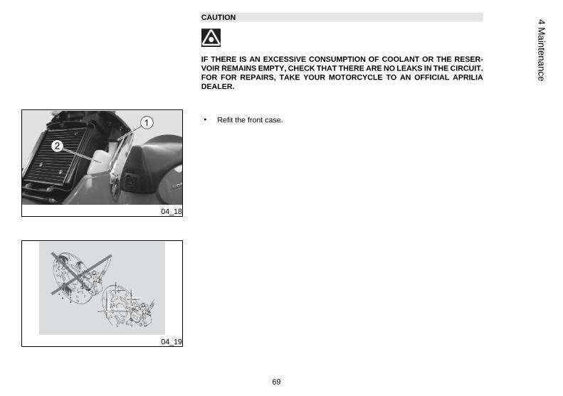
IF THERE IS AN EXCESSIVE CONSUMPTION OF COOLANT OR THE RESER-VOIR REMAINS EMPTY, CHECK THAT THERE ARE NO LEAKS IN THE CIRCUIT.FOR FOR REPAIRS, TAKE YOUR MOTORCYCLE TO AN OFFICIAL APRILIADEALER.
04_18
• Refit the front case.
04_19
69
4 Maintenance
Checking the brake oil level (04_19)
This vehicle is fitted with a braking system made up of:
• A front disc brake;• A rear disc brake;
Operating the right (front) brake lever exerts pressure on the front brake calliper. Op-erating the left (rear) brake lever exerts pressure on the front and rear brake callipers.
NOTE
THIS VEHICLE IS FITTED WITH AN INTEGRAL BRAKING SYSTEM.
CAUTION
UNEXPECTED CLEARANCE VARIATIONS OR ELASTIC RESISTANCE IN THEBRAKE LEVER ARE DUE TO FAILURE IN THE HYDRAULIC CIRCUIT. CONTACTAN Official Aprilia Dealer IN CASE OF DOUBTS ON THE CORRECT OPERATIONOF THE BRAKING SYSTEM OR WHEN UNABLE TO CARRY OUT ROUTINECHECK PROCEDURES.
CAUTION
PAY SPECIAL ATTENTION TO THE BRAKE DISC AND THE FRICTION GASKETSAND CHECK THAT THEY ARE NOT OILY OR GREASY, SPECIALLY AFTERMAINTENANCE OPERATIONS OR CHECKS. CHECK THAT THE BRAKE PIPE ISNOT TWISTED OR WORN.
KEEP OUT OF THE REACH OF CHILDREN.
DO NOT DISPOSE OF THE FLUID INTO THE ENVIRONMENT.
When the friction pads wear out, the brake fluid level in the reservoir goes down toautomatically compensate for that wear.
70
4 M
aint
enan
ce
The brake fluid reservoirs are located on the handlebar, near the brake lever attach-ments.
Check frequently the brake fluid level in the reservoirs and the brake pad wear.
CAUTION
DO NOT USE YOUR MOTORCYCLE IF A FLUID LEAK IN THE BRAKING CIRCUITIS DETECTED.
Checking
To check level:
CAUTION
PARK THE MOTORCYCLE ON SAFE AND LEVEL GROUND.
• Rest the vehicle on its centre stand.• Turn the handlebar so that the fluid in the brake fluid reservoir is parallel to
the «MIN» reference mark indicated on the sight glass «1».• Check that the level in the reservoir is over the reference "MIN" indicated on
the sight glass "1".MIN = minimum level.
If the fluid does not reach at least the «MIN» reference mark:
CAUTION
FLUID LEVEL DECREASES GRADUALLY AS BRAKE PADS WEAR DOWN.
71
4 Maintenance
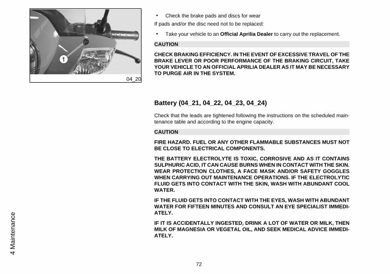
04_20
• Check the brake pads and discs for wearIf pads and/or the disc need not to be replaced:
• Take your vehicle to an Official Aprilia Dealer to carry out the replacement.
CAUTION
CHECK BRAKING EFFICIENCY. IN THE EVENT OF EXCESSIVE TRAVEL OF THEBRAKE LEVER OR POOR PERFORMANCE OF THE BRAKING CIRCUIT, TAKEYOUR VEHICLE TO AN OFFICIAL APRILIA DEALER AS IT MAY BE NECESSARYTO PURGE AIR IN THE SYSTEM.
Battery (04_21, 04_22, 04_23, 04_24)
Check that the leads are tightened following the instructions on the scheduled main-tenance table and according to the engine capacity.
CAUTION
FIRE HAZARD. FUEL OR ANY OTHER FLAMMABLE SUBSTANCES MUST NOTBE CLOSE TO ELECTRICAL COMPONENTS.
THE BATTERY ELECTROLYTE IS TOXIC, CORROSIVE AND AS IT CONTAINSSULPHURIC ACID, IT CAN CAUSE BURNS WHEN IN CONTACT WITH THE SKIN.WEAR PROTECTION CLOTHES, A FACE MASK AND/OR SAFETY GOGGLESWHEN CARRYING OUT MAINTENANCE OPERATIONS. IF THE ELECTROLYTICFLUID GETS INTO CONTACT WITH THE SKIN, WASH WITH ABUNDANT COOLWATER.
IF THE FLUID GETS INTO CONTACT WITH THE EYES, WASH WITH ABUNDANTWATER FOR FIFTEEN MINUTES AND CONSULT AN EYE SPECIALIST IMMEDI-ATELY.
IF IT IS ACCIDENTALLY INGESTED, DRINK A LOT OF WATER OR MILK, THENMILK OF MAGNESIA OR VEGETAL OIL, AND SEEK MEDICAL ADVICE IMMEDI-ATELY.
72
4 M
aint
enan
ce
THE BATTERY RELEASES EXPLOSIVE GASES. KEEP IT AWAY OF FLAMES,SPARKS, CIGARETTES OR ANY OTHER HEAT SOURCE.
WHEN RECHARGING OR USING THE BATTERY, BE CAREFUL TO HAVE THEROOM ADEQUATELY AIRED. DO NOT BREATH GASES RELEASED WHEN THEBATTERY IS BEING RECHARGED.
KEEP OUT OF THE REACH OF CHILDREN.
PAY ATTENTION NOT TO TILT THE MOTORCYCLE EXCESSIVELY TO AVOIDDANGEROUS SPILLS OF BATTERY FLUID.
CAUTION
DO NOT INVERT THE CONNECTIONS OF THE BATTERY LEADS.
CONNECT AND DISCONNECT THE BATTERY WITH THE IGNITION SWITCH SETTO «OFF» OR THIS MAY DAMAGE SOME COMPONENTS. CONNECT THE POS-ITIVE LEAD (+) FIRST AND THEN THE NEGATIVE ONE (-). DISCONNECT IN THEREVERSE ORDER.
BATTERY FLUID IS CORROSIVE.
DO NOT POUR OR SPREAD IT ESPECIALLY ON PLASTIC PARTS.
WHEN RECHARGING A "MAINTENANCE FREE" BATTERY INSTALLED USE ASPECIFIC BATTERY CHARGER (VOLTAGE/CONSTANT AMPERAGE OR CON-STANT VOLTAGE TYPE).
USING A CONVENTIONAL BATTERY CHARGER MAY DAMAGE THE BATTERY.
Battery removal
73
4 Maintenance
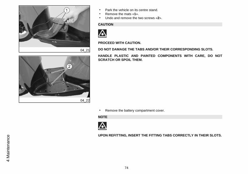
04_21
04_22
• Park the vehicle on its centre stand.• Remove the mats «1».• Undo and remove the two screws «2».
CAUTION
PROCEED WITH CAUTION.
DO NOT DAMAGE THE TABS AND/OR THEIR CORRESPONDING SLOTS.
HANDLE PLASTIC AND PAINTED COMPONENTS WITH CARE, DO NOTSCRATCH OR SPOIL THEM.
• Remove the battery compartment cover.
NOTE
UPON REFITTING, INSERT THE FITTING TABS CORRECTLY IN THEIR SLOTS.
74
4 M
aint
enan
ce
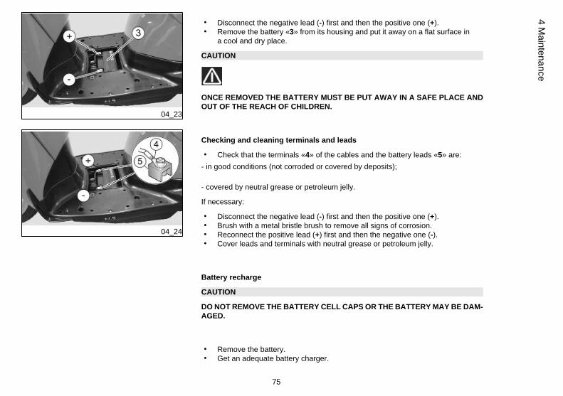
04_23
• Disconnect the negative lead (-) first and then the positive one (+).• Remove the battery «3» from its housing and put it away on a flat surface in
a cool and dry place.
CAUTION
ONCE REMOVED THE BATTERY MUST BE PUT AWAY IN A SAFE PLACE ANDOUT OF THE REACH OF CHILDREN.
04_24
Checking and cleaning terminals and leads
• Check that the terminals «4» of the cables and the battery leads «5» are:- in good conditions (not corroded or covered by deposits);
- covered by neutral grease or petroleum jelly.
If necessary:
• Disconnect the negative lead (-) first and then the positive one (+).• Brush with a metal bristle brush to remove all signs of corrosion.• Reconnect the positive lead (+) first and then the negative one (-).• Cover leads and terminals with neutral grease or petroleum jelly.
Battery recharge
CAUTION
DO NOT REMOVE THE BATTERY CELL CAPS OR THE BATTERY MAY BE DAM-AGED.
• Remove the battery.• Get an adequate battery charger.
75
4 Maintenance
• Set the battery charger for a slow recharge.• Connect the battery to the battery charger.
CAUTION
WHEN RECHARGING OR USING THE BATTERY, BE CAREFUL TO HAVE THEROOM ADEQUATELY AIRED. DO NOT BREATH GASES RELEASED WHEN THEBATTERY IS RECHARGING.
• Switch on the battery charger.
04_25
04_26
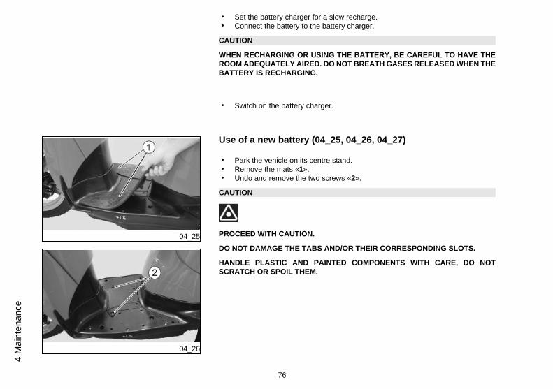
Use of a new battery (04_25, 04_26, 04_27)
• Park the vehicle on its centre stand.• Remove the mats «1».• Undo and remove the two screws «2».
CAUTION
PROCEED WITH CAUTION.
DO NOT DAMAGE THE TABS AND/OR THEIR CORRESPONDING SLOTS.
HANDLE PLASTIC AND PAINTED COMPONENTS WITH CARE, DO NOTSCRATCH OR SPOIL THEM.
76
4 M
aint
enan
ce
• Remove the battery compartment cover.
NOTE
UPON REFITTING, INSERT THE FITTING TABS CORRECTLY IN THEIR SLOTS.
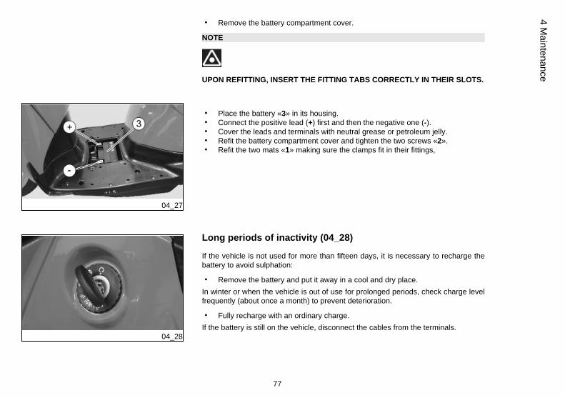
04_27
• Place the battery «3» in its housing.• Connect the positive lead (+) first and then the negative one (-).• Cover the leads and terminals with neutral grease or petroleum jelly.• Refit the battery compartment cover and tighten the two screws «2».• Refit the two mats «1» making sure the clamps fit in their fittings,
04_28
Long periods of inactivity (04_28)
If the vehicle is not used for more than fifteen days, it is necessary to recharge thebattery to avoid sulphation:
• Remove the battery and put it away in a cool and dry place.In winter or when the vehicle is out of use for prolonged periods, check charge levelfrequently (about once a month) to prevent deterioration.
• Fully recharge with an ordinary charge.If the battery is still on the vehicle, disconnect the cables from the terminals.
77
4 Maintenance
Lamps
CAUTION
FIRE HAZARD. FUEL OR ANY OTHER FLAMMABLE SUBSTANCES MUST NOTBE CLOSE TO ELECTRICAL COMPONENTS.
CAUTION
BEFORE REPLACING A BULB, TURN THE IGNITION SWITCH TO «KEY OFF»AND WAIT A FEW MINUTES FOR THE BULB TO COOL OFF.
WEAR CLEAN GLOVES OR USE A CLEAN DRY CLOTH TO REPLACE THEBULB.
DO NOT LEAVE PRINTS ON THE BULB AS THIS MAY CAUSE IT TO OVERHEATOR EVEN BLOW OUT. IF YOU TOUCH THE BULB WITHOUT WEARING GLOVES,CLEAN OFF PRINTS WITH ALCOHOL TO AVOID DAMAGING THE BULB.
DO NOT FORCE ELECTRICAL CABLES.
NOTE
BEFORE REPLACING A BULB, CHECK THE FUSES.
BULBS/WARNING LIGHTS(*) Cannot be replaced
High/low beam bulb 12 V 60/55 W H4
Tail light bulb 12V - 5W
78
4 M
aint
enan
ce
Front and rear turn indicator bulbs 12V - 10 W (RY amber bulb)
License plate light bulb 12V - 5W
Rear daylight running light /stoplight bulb
12V - 5/21W
Instrument panel lighting bulb (*) LED
Turn indicator warning light (*) LED
High beam warning light (*) LED
Low fuel warning light (*) LED
04_29
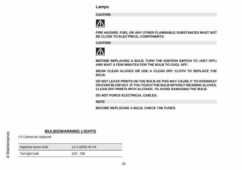
Front light group (04_29, 04_30, 04_31, 04_32, 04_33, 04_34,04_35, 04_36)
In the headlamp there are:• One low/high beam light bulb «1»;• One tail light bulb «2»;
For replacement:
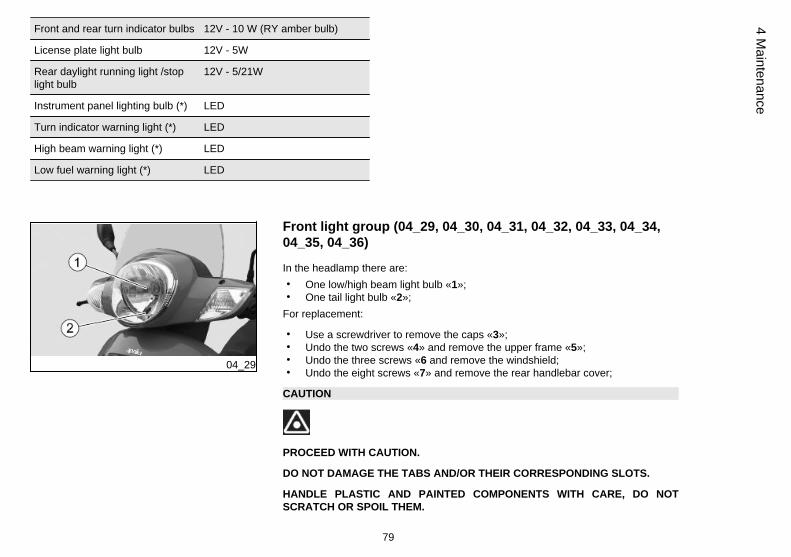
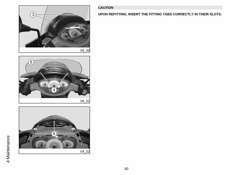
• Use a screwdriver to remove the caps «3»;• Undo the two screws «4» and remove the upper frame «5»;• Undo the three screws «6 and remove the windshield;• Undo the eight screws «7» and remove the rear handlebar cover;
CAUTION
PROCEED WITH CAUTION.
DO NOT DAMAGE THE TABS AND/OR THEIR CORRESPONDING SLOTS.
HANDLE PLASTIC AND PAINTED COMPONENTS WITH CARE, DO NOTSCRATCH OR SPOIL THEM.
79
4 Maintenance
04_30
04_31
04_32
CAUTION
UPON REFITTING, INSERT THE FITTING TABS CORRECTLY IN THEIR SLOTS.
80
4 M
aint
enan
ce
04_33
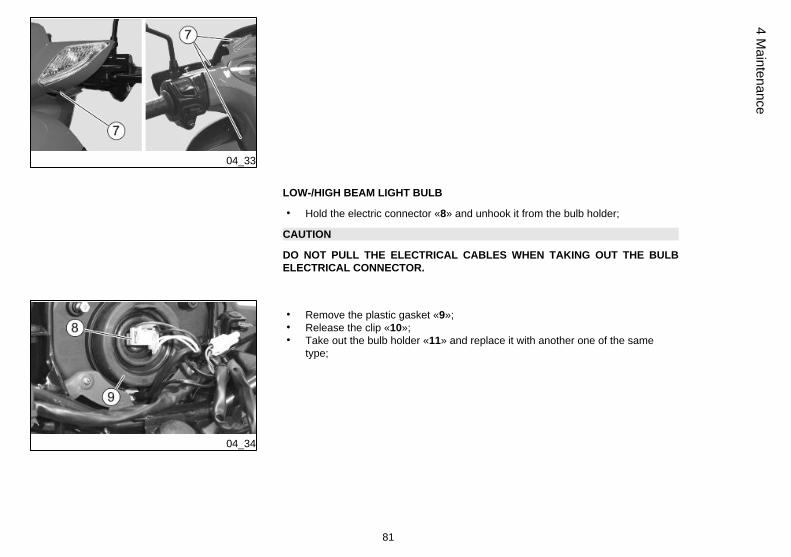
LOW-/HIGH BEAM LIGHT BULB
• Hold the electric connector «8» and unhook it from the bulb holder;
CAUTION
DO NOT PULL THE ELECTRICAL CABLES WHEN TAKING OUT THE BULBELECTRICAL CONNECTOR.
04_34
• Remove the plastic gasket «9»;• Release the clip «10»;• Take out the bulb holder «11» and replace it with another one of the same
type;
81
4 Maintenance
04_35
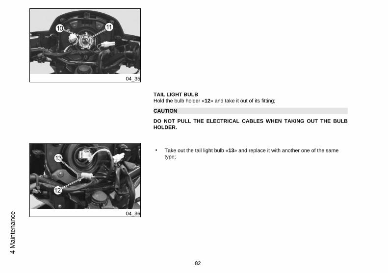
TAIL LIGHT BULBHold the bulb holder «12» and take it out of its fitting;
CAUTION
DO NOT PULL THE ELECTRICAL CABLES WHEN TAKING OUT THE BULBHOLDER.
04_36
• Take out the tail light bulb «13» and replace it with another one of the sametype;
82
4 M
aint
enan
ce
04_37
04_38
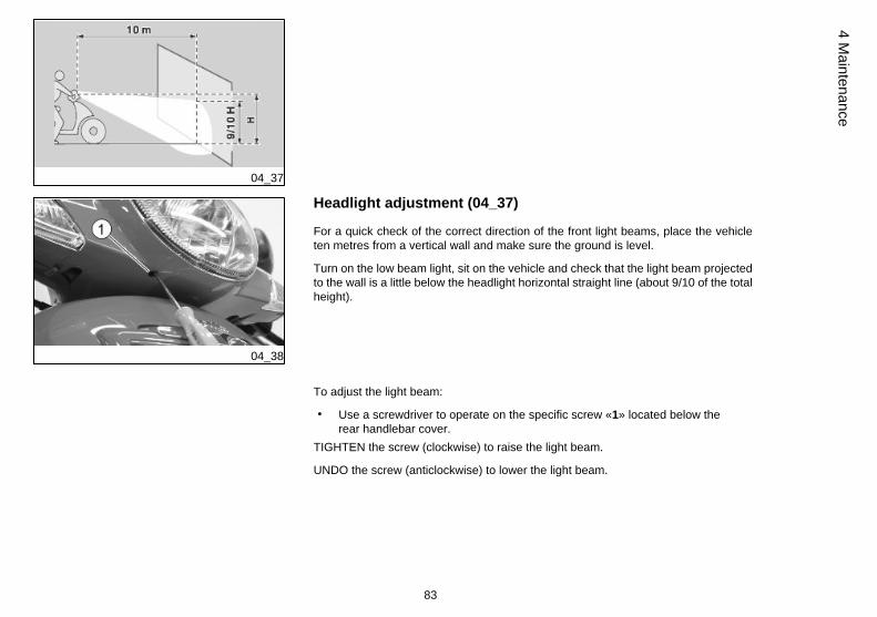
Headlight adjustment (04_37)
For a quick check of the correct direction of the front light beams, place the vehicleten metres from a vertical wall and make sure the ground is level.
Turn on the low beam light, sit on the vehicle and check that the light beam projectedto the wall is a little below the headlight horizontal straight line (about 9/10 of the totalheight).
To adjust the light beam:
• Use a screwdriver to operate on the specific screw «1» located below therear handlebar cover.
TIGHTEN the screw (clockwise) to raise the light beam.
UNDO the screw (anticlockwise) to lower the light beam.
83
4 Maintenance
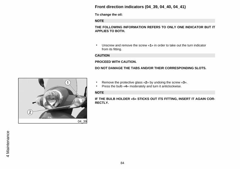
Front direction indicators (04_39, 04_40, 04_41)
To change the oil:
NOTE
THE FOLLOWING INFORMATION REFERS TO ONLY ONE INDICATOR BUT ITAPPLIES TO BOTH.
• Unscrew and remove the screw «1» in order to take out the turn indicatorfrom its fitting.
CAUTION
PROCEED WITH CAUTION.
DO NOT DAMAGE THE TABS AND/OR THEIR CORRESPONDING SLOTS.
04_39
• Remove the protective glass «2» by undoing the screw «3».• Press the bulb «4» moderately and turn it anticlockwise.
NOTE
IF THE BULB HOLDER «5» STICKS OUT ITS FITTING, INSERT IT AGAIN COR-RECTLY.
84
4 M
aint
enan
ce
04_40
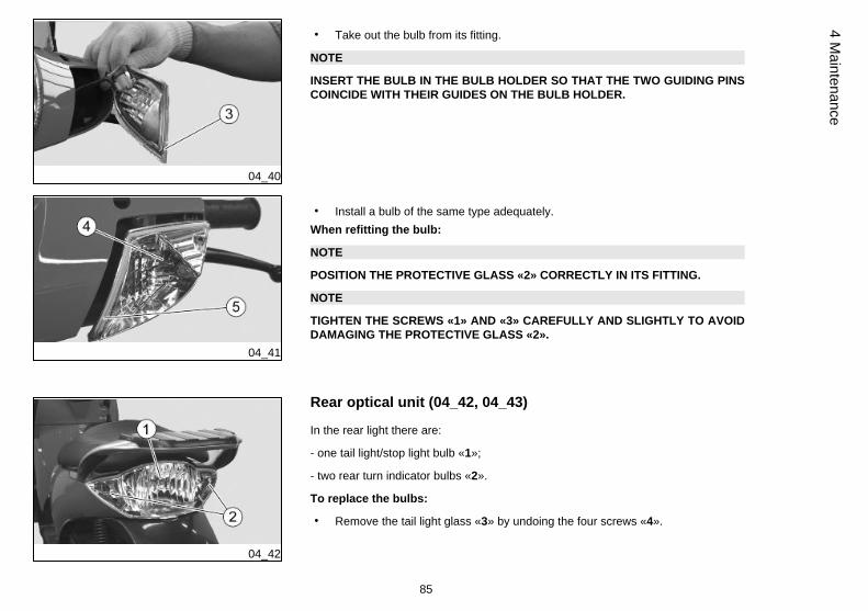
• Take out the bulb from its fitting.
NOTE
INSERT THE BULB IN THE BULB HOLDER SO THAT THE TWO GUIDING PINSCOINCIDE WITH THEIR GUIDES ON THE BULB HOLDER.
04_41
• Install a bulb of the same type adequately.When refitting the bulb:
NOTE
POSITION THE PROTECTIVE GLASS «2» CORRECTLY IN ITS FITTING.
NOTE
TIGHTEN THE SCREWS «1» AND «3» CAREFULLY AND SLIGHTLY TO AVOIDDAMAGING THE PROTECTIVE GLASS «2».
04_42
Rear optical unit (04_42, 04_43)
In the rear light there are:
- one tail light/stop light bulb «1»;
- two rear turn indicator bulbs «2».
To replace the bulbs:
• Remove the tail light glass «3» by undoing the four screws «4».
85
4 Maintenance
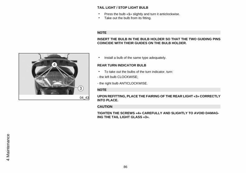
TAIL LIGHT / STOP LIGHT BULB
• Press the bulb «1» slightly and turn it anticlockwise.• Take out the bulb from its fitting.
NOTE
INSERT THE BULB IN THE BULB HOLDER SO THAT THE TWO GUIDING PINSCOINCIDE WITH THEIR GUIDES ON THE BULB HOLDER.
04_43
• Install a bulb of the same type adequately.
REAR TURN INDICATOR BULB
• To take out the bulbs of the turn indicator, turn:- the left bulb CLOCKWISE;
- the right bulb ANTICLOCKWISE.
NOTE
UPON REFITTING, PLACE THE FAIRING OF THE REAR LIGHT «3» CORRECTLYINTO PLACE.
CAUTION
TIGHTEN THE SCREWS «4» CAREFULLY AND SLIGHTLY TO AVOID DAMAG-ING THE TAIL LIGHT GLASS «3».
86
4 M
aint
enan
ce
04_44
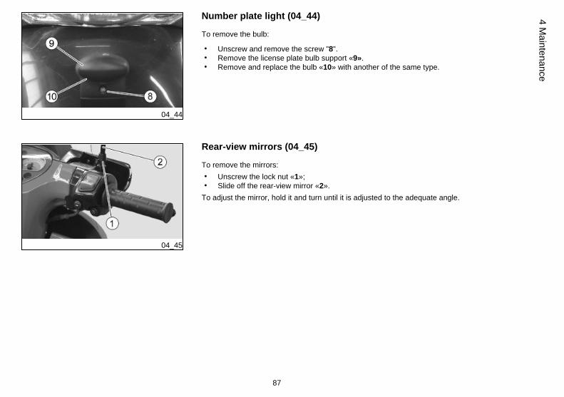
Number plate light (04_44)
To remove the bulb:
• Unscrew and remove the screw "8".• Remove the license plate bulb support «9».• Remove and replace the bulb «10» with another of the same type.
04_45
Rear-view mirrors (04_45)
To remove the mirrors:• Unscrew the lock nut «1»;• Slide off the rear-view mirror «2».
To adjust the mirror, hold it and turn until it is adjusted to the adequate angle.
87
4 Maintenance
04_46
04_47
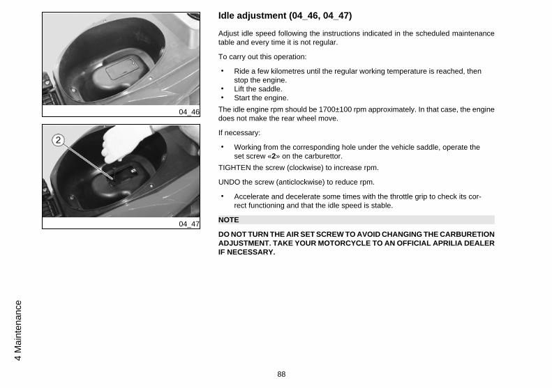
Idle adjustment (04_46, 04_47)
Adjust idle speed following the instructions indicated in the scheduled maintenancetable and every time it is not regular.
To carry out this operation:
• Ride a few kilometres until the regular working temperature is reached, thenstop the engine.
• Lift the saddle.• Start the engine.
The idle engine rpm should be 1700±100 rpm approximately. In that case, the enginedoes not make the rear wheel move.
If necessary:
• Working from the corresponding hole under the vehicle saddle, operate theset screw «2» on the carburettor.
TIGHTEN the screw (clockwise) to increase rpm.
UNDO the screw (anticlockwise) to reduce rpm.
• Accelerate and decelerate some times with the throttle grip to check its cor-rect functioning and that the idle speed is stable.
NOTE
DO NOT TURN THE AIR SET SCREW TO AVOID CHANGING THE CARBURETIONADJUSTMENT. TAKE YOUR MOTORCYCLE TO AN OFFICIAL APRILIA DEALERIF NECESSARY.
88
4 M
aint
enan
ce
04_48
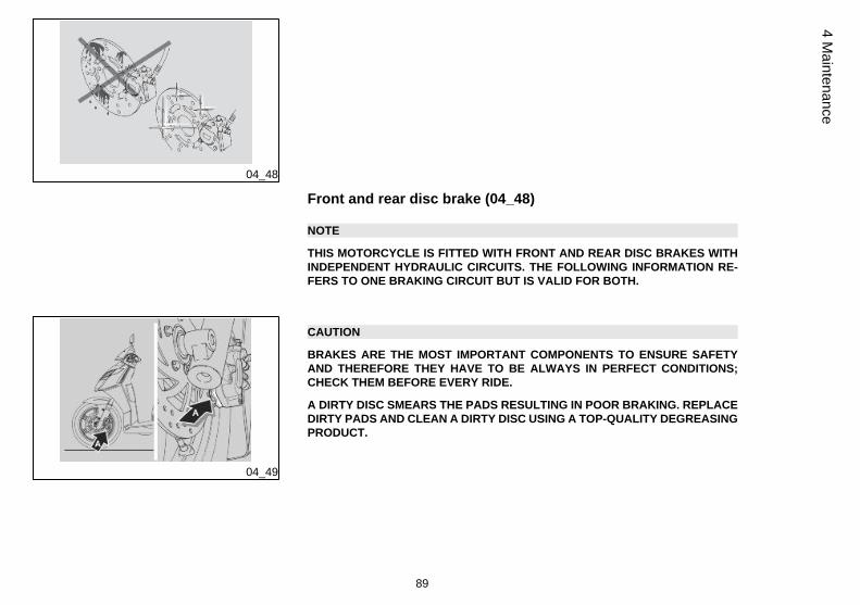
Front and rear disc brake (04_48)
NOTE
THIS MOTORCYCLE IS FITTED WITH FRONT AND REAR DISC BRAKES WITHINDEPENDENT HYDRAULIC CIRCUITS. THE FOLLOWING INFORMATION RE-FERS TO ONE BRAKING CIRCUIT BUT IS VALID FOR BOTH.
04_49
CAUTION
BRAKES ARE THE MOST IMPORTANT COMPONENTS TO ENSURE SAFETYAND THEREFORE THEY HAVE TO BE ALWAYS IN PERFECT CONDITIONS;CHECK THEM BEFORE EVERY RIDE.
A DIRTY DISC SMEARS THE PADS RESULTING IN POOR BRAKING. REPLACEDIRTY PADS AND CLEAN A DIRTY DISC USING A TOP-QUALITY DEGREASINGPRODUCT.
89
4 Maintenance
04_50
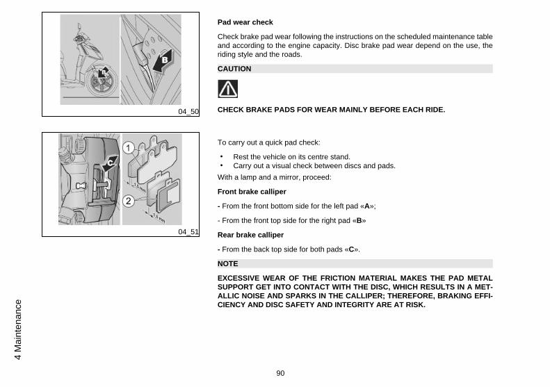
Pad wear check
Check brake pad wear following the instructions on the scheduled maintenance tableand according to the engine capacity. Disc brake pad wear depend on the use, theriding style and the roads.
CAUTION
CHECK BRAKE PADS FOR WEAR MAINLY BEFORE EACH RIDE.
04_51
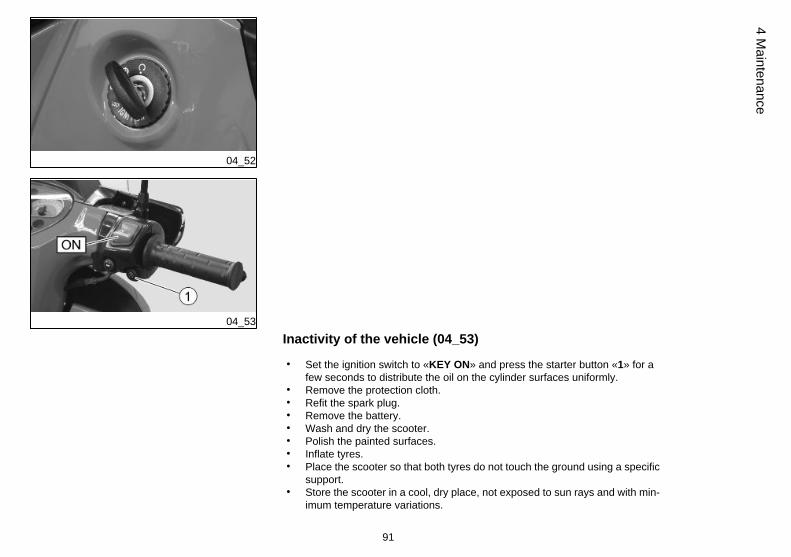
To carry out a quick pad check:
• Rest the vehicle on its centre stand.• Carry out a visual check between discs and pads.
With a lamp and a mirror, proceed:
Front brake calliper
- From the front bottom side for the left pad «A»;
- From the front top side for the right pad «B»
Rear brake calliper
- From the back top side for both pads «C».
NOTE
EXCESSIVE WEAR OF THE FRICTION MATERIAL MAKES THE PAD METALSUPPORT GET INTO CONTACT WITH THE DISC, WHICH RESULTS IN A MET-ALLIC NOISE AND SPARKS IN THE CALLIPER; THEREFORE, BRAKING EFFI-CIENCY AND DISC SAFETY AND INTEGRITY ARE AT RISK.
90
4 M
aint
enan
ce
04_52
04_53
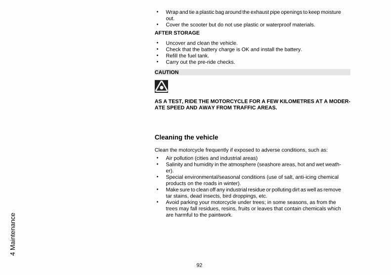
Inactivity of the vehicle (04_53)
• Set the ignition switch to «KEY ON» and press the starter button «1» for afew seconds to distribute the oil on the cylinder surfaces uniformly.
• Remove the protection cloth.• Refit the spark plug.• Remove the battery.• Wash and dry the scooter.• Polish the painted surfaces.• Inflate tyres.• Place the scooter so that both tyres do not touch the ground using a specific
support.• Store the scooter in a cool, dry place, not exposed to sun rays and with min-
imum temperature variations.
91
4 Maintenance
• Wrap and tie a plastic bag around the exhaust pipe openings to keep moistureout.
• Cover the scooter but do not use plastic or waterproof materials.AFTER STORAGE
• Uncover and clean the vehicle.• Check that the battery charge is OK and install the battery.• Refill the fuel tank.• Carry out the pre-ride checks.
CAUTION
AS A TEST, RIDE THE MOTORCYCLE FOR A FEW KILOMETRES AT A MODER-ATE SPEED AND AWAY FROM TRAFFIC AREAS.
Cleaning the vehicle
Clean the motorcycle frequently if exposed to adverse conditions, such as:• Air pollution (cities and industrial areas)• Salinity and humidity in the atmosphere (seashore areas, hot and wet weath-
er).• Special environmental/seasonal conditions (use of salt, anti-icing chemical
products on the roads in winter).• Make sure to clean off any industrial residue or polluting dirt as well as remove
tar stains, dead insects, bird droppings, etc.• Avoid parking your motorcycle under trees; in some seasons, as from the
trees may fall residues, resins, fruits or leaves that contain chemicals whichare harmful to the paintwork.
92
4 M
aint
enan
ce
CAUTION
AFTER CLEANING YOUR MOTORCYCLE, BRAKING EFFICIENCY MAY BE TEM-PORARILY AFFECTED DUE TO THE PRESENCE OF WATER ON THE FRICTIONSURFACES OF THE BRAKING CIRCUIT. ALLOW LONGER BRAKING DISTAN-CES TO PREVENT ACCIDENTS. BRAKE REPEATEDLY TO RESTORE NORMALOPERATION. CARRY OUT THE PRE-RIDE CHECKS.
To clean off dirt and mud deposited from painted surfaces, soften caked dirt with alow-pressure water jet. Sponge off using a car body sponge soaked in a car bodyshampoo and water solution (2 - 4% parts of shampoo in water).
Then rinse with plenty of water, and dry with a chamois leather. To clean the engineouter parts, use degreasing detergent, brushes and old cloths.
CAUTION
TO CLEAN THE HEADLIGHTS USE A SPONGE SOAKED IN WATER AND MILDDETERGENT, RUBBING THE SURFACE GENTLY AND RINSING FREQUENTLYWITH PLENTY OF WATER.
REMEMBER TO CLEAN THE VEHICLE CAREFULLY BEFORE ANY POLISHINGWITH SILICON WAX.
DO NOT USE ABRASIVE PASTES TO POLISH MATT FINISH PAINTWORK.
THE VEHICLE SHOULD NEVER BE WASHED IN DIRECT SUNLIGHT, ESPECIAL-LY DURING SUMMER, WITH THE BODYWORK STILL HOT, AS THE SHAMPOOCAN DAMAGE THE PAINTWORK IF IT DRIES BEFORE BEING RINSED OFF.
DO NOT USE LIQUIDS AT TEMPERATURES OVER 40 °C WHEN CLEANINGPLASTIC PARTS OF THE VEHICLE.
DO NOT AIM HIGH PRESSURE AIR/WATER JETS OR STEAM JETS DIRECTLYTO THE FOLLOWING PARTS: WHEEL HUBS, CONTROLS ON THE RIGHT ANDLEFT SIDES OF THE HANDLEBAR, BEARINGS, BRAKE PUMPS, INSTRUMENTSAND GAUGES, MUFFLER EXHAUST, GLOVE-BOX/TOOL KIT COMPARTMENT,
93
4 Maintenance
IGNITION SWITCH /STEERING LOCK, RADIATOR FINS, FUEL TANK CAP,HEADLAMPS AND ELECTRICAL CONNECTIONS.
DO NOT USE ALCOHOL, PETROL OR SOLVENTS TO CLEAN RUBBER ANDPLASTIC PARTS. USE ONLY WATER AND NEUTRAL SOAP INSTEAD. DO NOTUSE SOLVENTS OR PETROL BY-PRODUCTS (ACETONE, TRICHLOROETHY-LENE, TURPENTINE, PETROL, THINNERS) TO CLEAN THE SADDLE. USE IN-STEAD DETERGENTS WITH SURFACE ACTIVE AGENTS NOT EXCEEDING 5%(NEUTRAL SOAP, DEGREASING DETERGENTS) OR ALCOHOL. DRY THE SAD-DLE WELL AFTER CLEANING.
CAUTION
DO NOT APPLY PROTECTIVE WAX ON THE SADDLE AS IT MAY BECOME SLIP-PERY.
Transport
CAUTION
BEFORE TRANSPORTING THE VEHICLE, EMPTY THE FUEL TANK WELL ANDMAKE SURE IT IS PERFECTLY DRY.
DURING TRANSPORT, THE VEHICLE SHOULD BE AT ALL TIMES UPRIGHT ANDWELL ANCHORED SO AS TO AVOID FUEL, OIL OR COOLANT LEAKS.
IN CASE OF FAILURE, DO NOT HAVE THE MOTORCYCLE TOWED. ASK FORAN ADEQUATE ASSISTANCE.
EMPTYING THE FUEL TANK
CAUTION
FIRE HAZARD.
WAIT UNTIL THE ENGINE AND THE MUFFLER ARE COLD.
94
4 M
aint
enan
ce
FUEL VAPOURS ARE HARMFUL TO HEALTH.
BEFORE ANY OPERATION, MAKE SURE THAT THE ROOM WHERE YOU AREHAS ADEQUATE AIR VENTILATION.
DO NOT INHALE FUEL VAPOURS.
DO NOT DISPOSE OF FUEL INTO THE ENVIRONMENT.
• Rest the vehicle on its centre stand.• Shut off the engine and wait until it cools off.• Get a container, with more capacity than the fuel in the tank, and put it on the
ground to the left of the vehicle.• Remove the fuel tank cap.• Use a hand-operated pump or a similar system to empty the fuel tank. Take
care not to damage the pump unit (probe checking fuel level in the tank).
CAUTION
AFTER EMPTYING THE TANK, REFIT THE FUEL TANK CAP.
95
4 Maintenance

96
4 M
aint
enan
ce

SCARABEO 125 - 200Chap. 05
Technical data
97
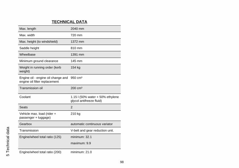
TECHNICAL DATAMax. length 2040 mm
Max. width 720 mm
Max. height (to windshield) 1372 mm
Saddle height 810 mm
Wheelbase 1391 mm
Minimum ground clearance 145 mm
Weight in running order (kerbweight)
154 kg
Engine oil - engine oil change andengine oil filter replacement
950 cm³
Transmission oil 200 cm³
Coolant 1.15 l (50% water + 50% ethyleneglycol antifreeze fluid)
Seats 2
Vehicle max. load (rider +passenger + luggage)
210 kg
Gearbox automatic continuous variator
Transmission V-belt and gear reduction unit.
Engine/wheel total ratio (125) minimum: 32.1
maximum: 9.9
Engine/wheel total ratio (200) minimum: 21.0
98
5 Te
chni
cal d
ata
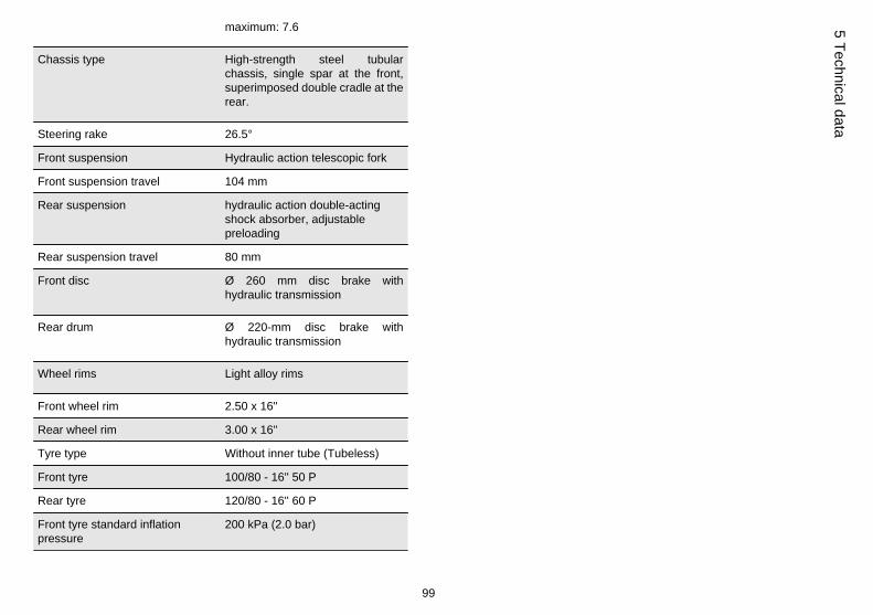
maximum: 7.6
Chassis type High-strength steel tubularchassis, single spar at the front,superimposed double cradle at therear.
Steering rake 26.5°
Front suspension Hydraulic action telescopic fork
Front suspension travel 104 mm
Rear suspension hydraulic action double-actingshock absorber, adjustablepreloading
Rear suspension travel 80 mm
Front disc Ø 260 mm disc brake withhydraulic transmission
Rear drum Ø 220-mm disc brake withhydraulic transmission
Wheel rims Light alloy rims
Front wheel rim 2.50 x 16''
Rear wheel rim 3.00 x 16''
Tyre type Without inner tube (Tubeless)
Front tyre 100/80 - 16'' 50 P
Rear tyre 120/80 - 16'' 60 P
Front tyre standard inflationpressure
200 kPa (2.0 bar)
99
5 Technical data
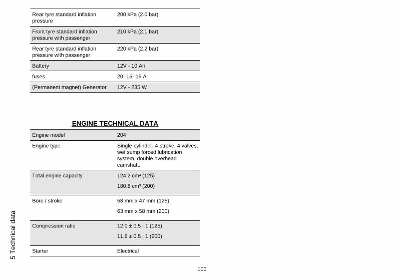
Rear tyre standard inflationpressure
200 kPa (2.0 bar)
Front tyre standard inflationpressure with passenger
210 kPa (2.1 bar)
Rear tyre standard inflationpressure with passenger
220 kPa (2.2 bar)
Battery 12V - 10 Ah
fuses 20- 15- 15 A
(Permanent magnet) Generator 12V - 235 W
ENGINE TECHNICAL DATAEngine model 204
Engine type Single-cylinder, 4-stroke, 4 valves,wet sump forced lubricationsystem, double overheadcamshaft.
Total engine capacity 124.2 cm³ (125)
180.8 cm³ (200)
Bore / stroke 58 mm x 47 mm (125)
63 mm x 58 mm (200)
Compression ratio 12.0 ± 0.5 : 1 (125)
11.6 ± 0.5 : 1 (200)
Starter Electrical
100
5 Te
chni
cal d
ata
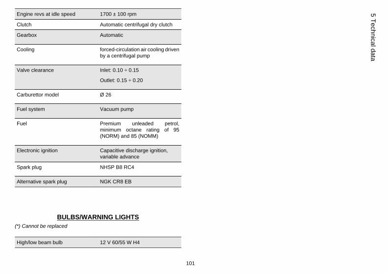
Engine revs at idle speed 1700 ± 100 rpm
Clutch Automatic centrifugal dry clutch
Gearbox Automatic
Cooling forced-circulation air cooling drivenby a centrifugal pump
Valve clearance Inlet: 0.10 ÷ 0.15
Outlet: 0.15 ÷ 0.20
Carburettor model Ø 26
Fuel system Vacuum pump
Fuel Premium unleaded petrol,minimum octane rating of 95(NORM) and 85 (NOMM)
Electronic ignition Capacitive discharge ignition,variable advance
Spark plug NHSP B8 RC4
Alternative spark plug NGK CR8 EB
BULBS/WARNING LIGHTS(*) Cannot be replaced
High/low beam bulb 12 V 60/55 W H4
101
5 Technical data
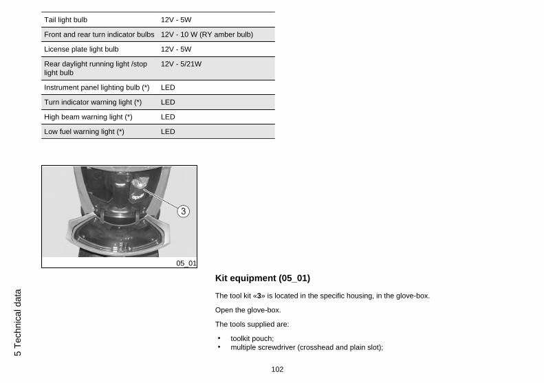
Tail light bulb 12V - 5W
Front and rear turn indicator bulbs 12V - 10 W (RY amber bulb)
License plate light bulb 12V - 5W
Rear daylight running light /stoplight bulb
12V - 5/21W
Instrument panel lighting bulb (*) LED
Turn indicator warning light (*) LED
High beam warning light (*) LED
Low fuel warning light (*) LED
05_01
Kit equipment (05_01)
The tool kit «3» is located in the specific housing, in the glove-box.
Open the glove-box.
The tools supplied are:
• toolkit pouch;• multiple screwdriver (crosshead and plain slot);
102
5 Te
chni
cal d
ata
• 16 mm box-spanner;• shock absorber adjustment wrench:• 4 mm spanner for Allen screws.
103
5 Technical data

104
5 Te
chni
cal d
ata
SCARABEO 125 - 200Chap. 06
Programmedmaintenance
105
Scheduled maintenance table
CAUTION
FIRE HAZARD.
FUEL OR ANY OTHER INFLAMMABLE SUBSTANCES MUST NOT BE CLOSE TOELECTRICAL COMPONENTS.
BEFORE ANY MAINTENANCE OPERATION OR INSPECTION ON THE MOTOR-CYCLE, SHUT OFF THE ENGINE AND REMOVE THE KEY. WAIT UNTIL THEENGINE AND THE EXHAUST SYSTEM ARE COLD, IF POSSIBLE LIFT THESCOOTER WITH A SPECIFIC TOOL ON A FIRM AND LEVEL GROUND.
BEFORE ANY OPERATION, MAKE SURE THAT THE ROOM WHERE YOU AREHAS ADEQUATE AIR VENTILATION.
TO AVOID BURNS BE SPECIALLY CAREFUL WITH HOT ENGINE AND EXHAUSTSYSTEM PARTS.
DO NOT HOLD ANY MECHANICAL OR OTHER MOTORCYCLE PARTS WITHYOUR MOUTH: MOTORCYCLE COMPONENT ARE NOT EDIBLE, ON THE CON-TRARY SOME OF THEM ARE HARMFUL AND EVEN TOXIC.
NOTE
UNLESS OTHERWISE INDICATED, REFIT THE UNITS FOLLOWING THE RE-MOVAL STEPS BUT IN REVERSE ORDER.
WHEN CARRYING OUT MAINTENANCE OPERATIONS, IT IS ADVISABLE TOWEAR LATEX GLOVES.
In general terms, routine maintenance operations can be carried out by the owner; insome cases it is necessary to use specific tools and have some technical knowledge.
106
6 Pr
ogra
mm
ed m
aint
enan
ce
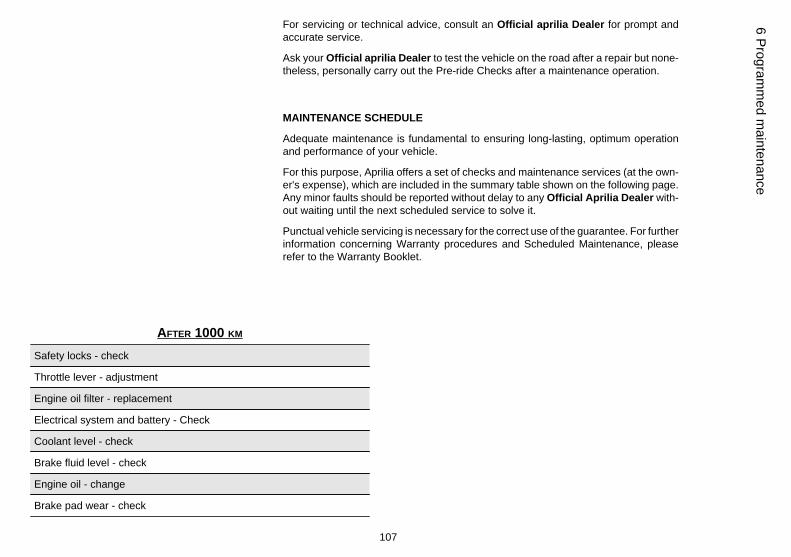
For servicing or technical advice, consult an Official aprilia Dealer for prompt andaccurate service.
Ask your Official aprilia Dealer to test the vehicle on the road after a repair but none-theless, personally carry out the Pre-ride Checks after a maintenance operation.
MAINTENANCE SCHEDULE
Adequate maintenance is fundamental to ensuring long-lasting, optimum operationand performance of your vehicle.
For this purpose, Aprilia offers a set of checks and maintenance services (at the own-er's expense), which are included in the summary table shown on the following page.Any minor faults should be reported without delay to any Official Aprilia Dealer with-out waiting until the next scheduled service to solve it.
Punctual vehicle servicing is necessary for the correct use of the guarantee. For furtherinformation concerning Warranty procedures and Scheduled Maintenance, pleaserefer to the Warranty Booklet.
AFTER 1000 KM
Safety locks - check
Throttle lever - adjustment
Engine oil filter - replacement
Electrical system and battery - Check
Coolant level - check
Brake fluid level - check
Engine oil - change
Brake pad wear - check
107
6 Programm
ed maintenance
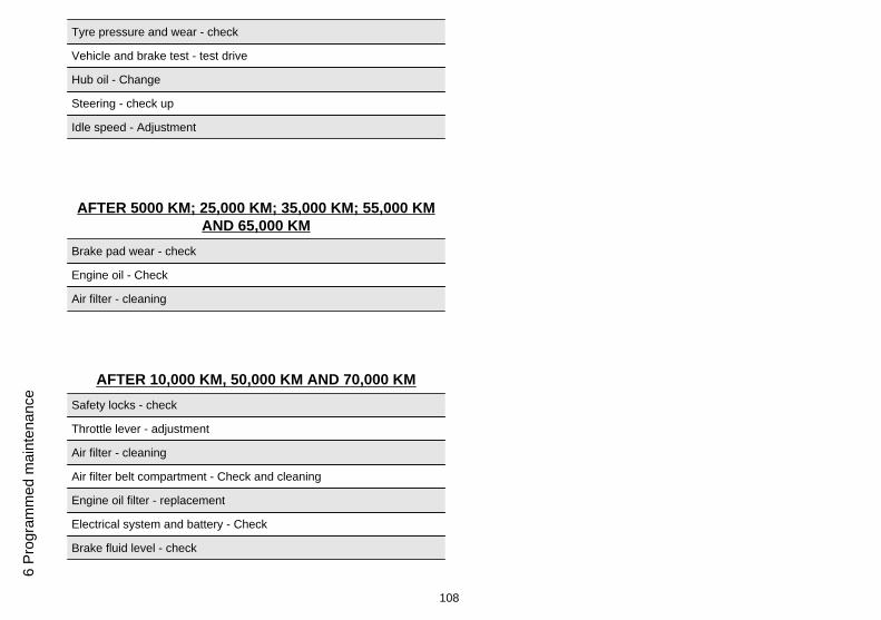
Tyre pressure and wear - check
Vehicle and brake test - test drive
Hub oil - Change
Steering - check up
Idle speed - Adjustment
AFTER 5000 KM; 25,000 KM; 35,000 KM; 55,000 KMAND 65,000 KM
Brake pad wear - check
Engine oil - Check
Air filter - cleaning
AFTER 10,000 KM, 50,000 KM AND 70,000 KMSafety locks - check
Throttle lever - adjustment
Air filter - cleaning
Air filter belt compartment - Check and cleaning
Engine oil filter - replacement
Electrical system and battery - Check
Brake fluid level - check
108
6 Pr
ogra
mm
ed m
aint
enan
ce
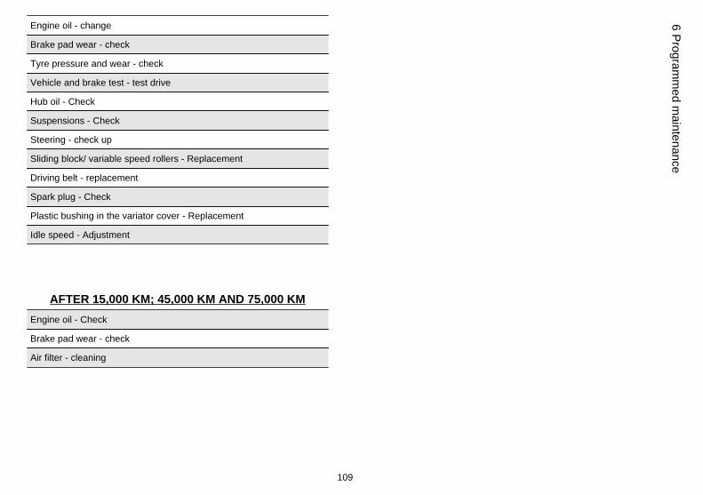
Engine oil - change
Brake pad wear - check
Tyre pressure and wear - check
Vehicle and brake test - test drive
Hub oil - Check
Suspensions - Check
Steering - check up
Sliding block/ variable speed rollers - Replacement
Driving belt - replacement
Spark plug - Check
Plastic bushing in the variator cover - Replacement
Idle speed - Adjustment
AFTER 15,000 KM; 45,000 KM AND 75,000 KMEngine oil - Check
Brake pad wear - check
Air filter - cleaning
109
6 Programm
ed maintenance
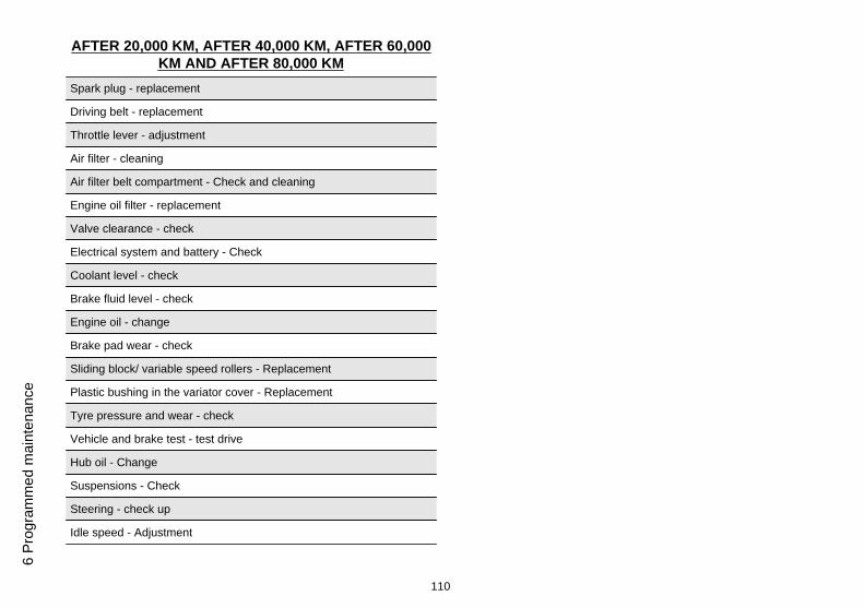
AFTER 20,000 KM, AFTER 40,000 KM, AFTER 60,000KM AND AFTER 80,000 KM
Spark plug - replacement
Driving belt - replacement
Throttle lever - adjustment
Air filter - cleaning
Air filter belt compartment - Check and cleaning
Engine oil filter - replacement
Valve clearance - check
Electrical system and battery - Check
Coolant level - check
Brake fluid level - check
Engine oil - change
Brake pad wear - check
Sliding block/ variable speed rollers - Replacement
Plastic bushing in the variator cover - Replacement
Tyre pressure and wear - check
Vehicle and brake test - test drive
Hub oil - Change
Suspensions - Check
Steering - check up
Idle speed - Adjustment
110
6 Pr
ogra
mm
ed m
aint
enan
ce
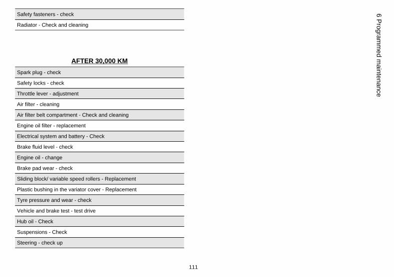
Safety fasteners - check
Radiator - Check and cleaning
AFTER 30,000 KMSpark plug - check
Safety locks - check
Throttle lever - adjustment
Air filter - cleaning
Air filter belt compartment - Check and cleaning
Engine oil filter - replacement
Electrical system and battery - Check
Brake fluid level - check
Engine oil - change
Brake pad wear - check
Sliding block/ variable speed rollers - Replacement
Plastic bushing in the variator cover - Replacement
Tyre pressure and wear - check
Vehicle and brake test - test drive
Hub oil - Check
Suspensions - Check
Steering - check up
111
6 Programm
ed maintenance
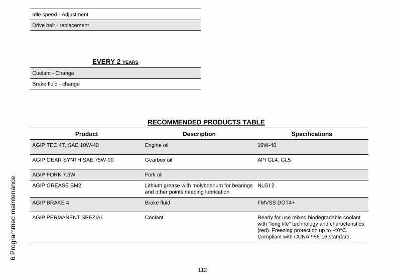
Idle speed - Adjustment
Drive belt - replacement
EVERY 2 YEARS
Coolant - Change
Brake fluid - change
RECOMMENDED PRODUCTS TABLEProduct Description Specifications
AGIP TEC 4T, SAE 10W-40 Engine oil 10W-40
AGIP GEAR SYNTH SAE 75W-90 Gearbox oil API GL4, GL5
AGIP FORK 7.5W Fork oil
AGIP GREASE SM2 Lithium grease with molybdenum for bearingsand other points needing lubrication
NLGI 2
AGIP BRAKE 4 Brake fluid FMVSS DOT4+
AGIP PERMANENT SPEZIAL Coolant Ready for use mixed biodegradable coolantwith "long life" technology and characteristics(red). Freezing protection up to -40°C.Compliant with CUNA 956-16 standard.
112
6 Pr
ogra
mm
ed m
aint
enan
ce

SCARABEO 125 - 200Chap. 07
Special fittings
113
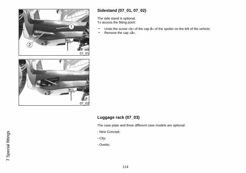
07_01
07_02
Sidestand (07_01, 07_02)
The side stand is optional.To access the fitting point:
• Undo the screw «1» of the cap 2» of the spoiler on the left of the vehicle;• Remove the cap «2».
Luggage rack (07_03)
The case plate and three different case models are optional:
- New Concept;
- City;
- Ovetto;
114
7 Sp
ecia
l fitt
ings
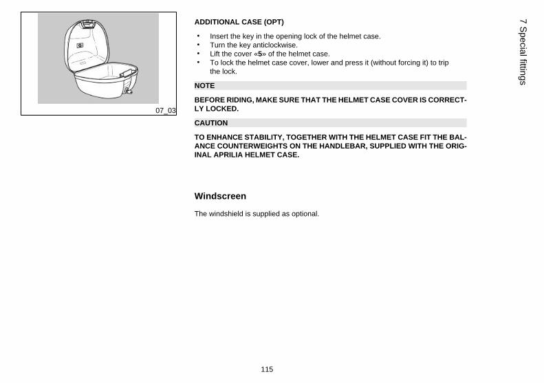
07_03
ADDITIONAL CASE (OPT)
• Insert the key in the opening lock of the helmet case.• Turn the key anticlockwise.• Lift the cover «5» of the helmet case.• To lock the helmet case cover, lower and press it (without forcing it) to trip
the lock.
NOTE
BEFORE RIDING, MAKE SURE THAT THE HELMET CASE COVER IS CORRECT-LY LOCKED.
CAUTION
TO ENHANCE STABILITY, TOGETHER WITH THE HELMET CASE FIT THE BAL-ANCE COUNTERWEIGHTS ON THE HANDLEBAR, SUPPLIED WITH THE ORIG-INAL APRILIA HELMET CASE.
Windscreen
The windshield is supplied as optional.
115
7 Special fittings

116
7 Sp
ecia
l fitt
ings
TABLE OF CONTENTS
AAir filter: 63, 64
BBattery: 72, 76Brake: 70, 89
DDisc brake: 89Display: 21
EEngine oil: 54–57Engine stop: 26
HHeadlight: 83Horn: 25
IIdentification: 29Instrument panel: 19
KKey switch: 23
LLight switch: 25Luggage rack: 114
MMaintenance: 53, 105, 106Maintenance Table: 106Mirrors: 87
Rrear-view mirrors: 87
SSaddle: 28Scheduled maintenance:106Shock absorber: 36Spark plug: 61Stand: 46Start-up: 26
TTechnical data: 97Tyres: 59
117
THE VALUE OF SERVICE
Thanks to continuous technical updates and specific training programs on aprilia products, only aprilia Official Network mechanics know this vehicle fully and have the special tools necessary to carryout maintenance and repair operations correctly.
The reliability of the vehicle also depends on its mechanical conditions. Checking the vehicle before riding, its regular maintenance and the use of Original aprilia Spare Parts only, are essential factors!
For information about the nearest Official Dealer and/or Service Centre, consult the Yellow Pages or search directly on the inset map in our Official Website:
www.aprilia.com
Only aprilia Original Spare Parts ensure products already studied and tested during the vehicle design stage. All aprilia Original Spare Parts undergo quality control procedures to guarantee full reliabilityand duration.
The descriptions and illustrations given in this publication are not binding; while the basic characteristics as described and illustrated in this manual remain unchanged, aprilia reserves the right, at anytime and without being required to update this publication beforehand, to make any changes to components, parts or accessories, which it considers necessary to improve the product or which are
required for manufacturing or construction reasons.
Not all versions/models shown in this publication are available in all countries. The availability of individual versions/models should be confirmed with the official Aprilia sales network.
© Copyright 2006- Aprilia. All rights reserved. Reproduction of this publication in whole or in part is prohibited. Aprilia - After-sales service.
Aprilia trademark is property of Piaggio & C. S.p.A.