Embed Size (px)
Citation preview
2010 SIMULIA Customer Conference 1
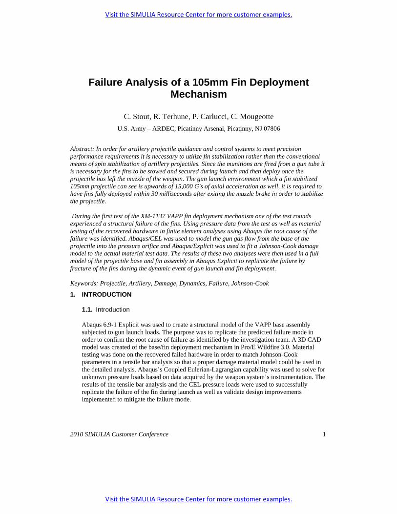
Failure Analysis of a 105mm Fin Deployment Mechanism
C. Stout, R. Terhune, P. Carlucci, C. Mougeotte
U.S. Army – ARDEC, Picatinny Arsenal, Picatinny, NJ 07806
Abstract: In order for artillery projectile guidance and control systems to meet precision performance requirements it is necessary to utilize fin stabilization rather than the conventional means of spin stabilization of artillery projectiles. Since the munitions are fired from a gun tube it is necessary for the fins to be stowed and secured during launch and then deploy once the projectile has left the muzzle of the weapon. The gun launch environment which a fin stabilized 105mm projectile can see is upwards of 15,000 G's of axial acceleration as well, it is required to have fins fully deployed within 30 milliseconds after exiting the muzzle brake in order to stabilize the projectile. During the first test of the XM-1137 VAPP fin deployment mechanism one of the test rounds experienced a structural failure of the fins. Using pressure data from the test as well as material testing of the recovered hardware in finite element analyses using Abaqus the root cause of the failure was identified. Abaqus/CEL was used to model the gun gas flow from the base of the projectile into the pressure orifice and Abaqus/Explicit was used to fit a Johnson-Cook damage model to the actual material test data. The results of these two analyses were then used in a full model of the projectile base and fin assembly in Abaqus Explicit to replicate the failure by fracture of the fins during the dynamic event of gun launch and fin deployment. Keywords: Projectile, Artillery, Damage, Dynamics, Failure, Johnson-Cook
1. INTRODUCTION
1.1. Introduction
Abaqus 6.9-1 Explicit was used to create a structural model of the VAPP base assembly subjected to gun launch loads. The purpose was to replicate the predicted failure mode in order to confirm the root cause of failure as identified by the investigation team. A 3D CAD model was created of the base/fin deployment mechanism in Pro/E Wildfire 3.0. Material testing was done on the recovered failed hardware in order to match Johnson-Cook parameters in a tensile bar analysis so that a proper damage material model could be used in the detailed analysis. Abaqus’s Coupled Eulerian-Lagrangian capability was used to solve for unknown pressure loads based on data acquired by the weapon system’s instrumentation. The results of the tensile bar analysis and the CEL pressure loads were used to successfully replicate the failure of the fin during launch as well as validate design improvements implemented to mitigate the failure mode.
Visit the SIMULIA Resource Center for more customer examples.
Visit the SIMULIA Resource Center for more customer examples.
2 2010 SIMULIA Customer Conference
2. DESIGN DESCRIPTION
2.1. Fin Deployment Mechanism Assembly
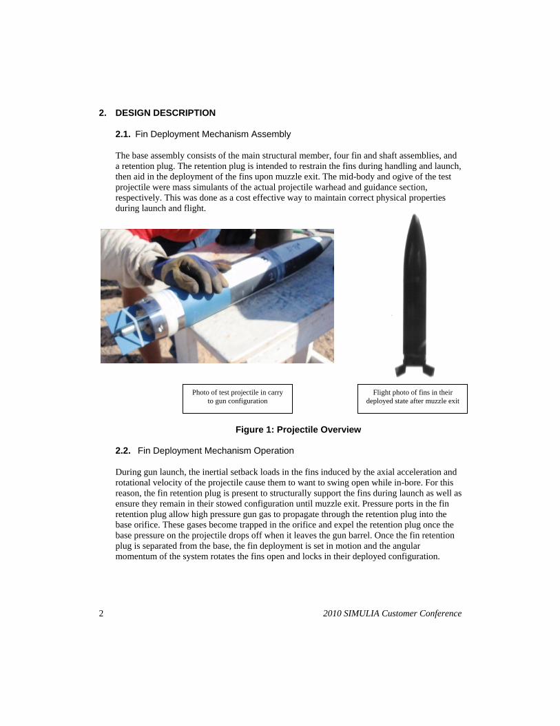
The base assembly consists of the main structural member, four fin and shaft assemblies, and a retention plug. The retention plug is intended to restrain the fins during handling and launch, then aid in the deployment of the fins upon muzzle exit. The mid-body and ogive of the test projectile were mass simulants of the actual projectile warhead and guidance section, respectively. This was done as a cost effective way to maintain correct physical properties during launch and flight.
Figure 1: Projectile Overview
2.2. Fin Deployment Mechanism Operation
During gun launch, the inertial setback loads in the fins induced by the axial acceleration and rotational velocity of the projectile cause them to want to swing open while in-bore. For this reason, the fin retention plug is present to structurally support the fins during launch as well as ensure they remain in their stowed configuration until muzzle exit. Pressure ports in the fin retention plug allow high pressure gun gas to propagate through the retention plug into the base orifice. These gases become trapped in the orifice and expel the retention plug once the base pressure on the projectile drops off when it leaves the gun barrel. Once the fin retention plug is separated from the base, the fin deployment is set in motion and the angular momentum of the system rotates the fins open and locks in their deployed configuration.
Flight photo of fins in their deployed state after muzzle exit
Photo of test projectile in carry to gun configuration
2010 SIMULIA Customer Conference 3
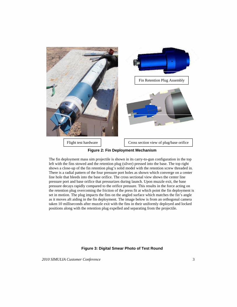
Figure 2: Fin Deployment Mechanism
The fin deployment mass sim projectile is shown in its carry-to-gun configuration in the top left with the fins stowed and the retention plug (silver) pressed into the base. The top right shows a close-up of the fin retention plug’s solid model with the retention screw threaded in. There is a radial pattern of the four pressure port holes as shown which converge on a center line hole that bleeds into the base orifice. The cross sectional view shows the center line pressure port and base orifice that pressurizes during launch. Upon muzzle exit, the base pressure decays rapidly compared to the orifice pressure. This results in the force acting on the retention plug overcoming the friction of the press fit at which point the fin deployment is set in motion. The plug impacts the fins on the angled surface which matches the fin’s angle as it moves aft aiding in the fin deployment. The image below is from an orthogonal camera taken 10 milliseconds after muzzle exit with the fins in their uniformly deployed and locked positions along with the retention plug expelled and separating from the projectile.
Figure 3: Digital Smear Photo of Test Round
Flight test hardware
Fin Retention Plug Assembly
Cross section view of plug/base orifice
4 2010 SIMULIA Customer Conference
2.3. Fin Failure
The first test series consisted of four test rounds, the first three of which successfully deployed fins and flew stable down range. The fourth round exited the muzzle of the weapon and appeared to have all four fins broken off. Further investigation of the gun tube showed signs of the fins impacting the gun tube wall just after shot start and proceeding down the tube wall.
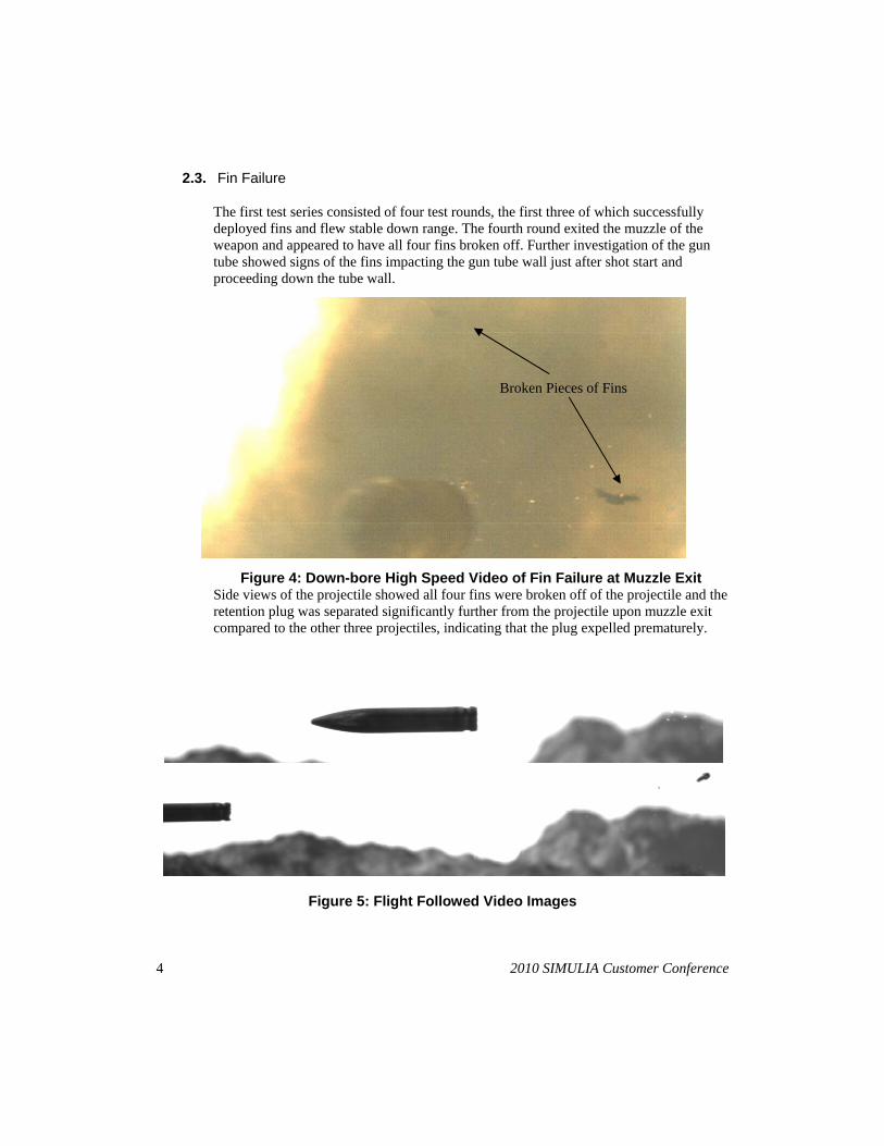
Figure 4: Down-bore High Speed Video of Fin Failure at Muzzle Exit Side views of the projectile showed all four fins were broken off of the projectile and the retention plug was separated significantly further from the projectile upon muzzle exit compared to the other three projectiles, indicating that the plug expelled prematurely.
Figure 5: Flight Followed Video Images
Broken Pieces of Fins
2010 SIMULIA Customer Conference 5
3. PRELIMINARY ANALYSES
3.1. Abaqus CEL Analysis of Orifice Pressure
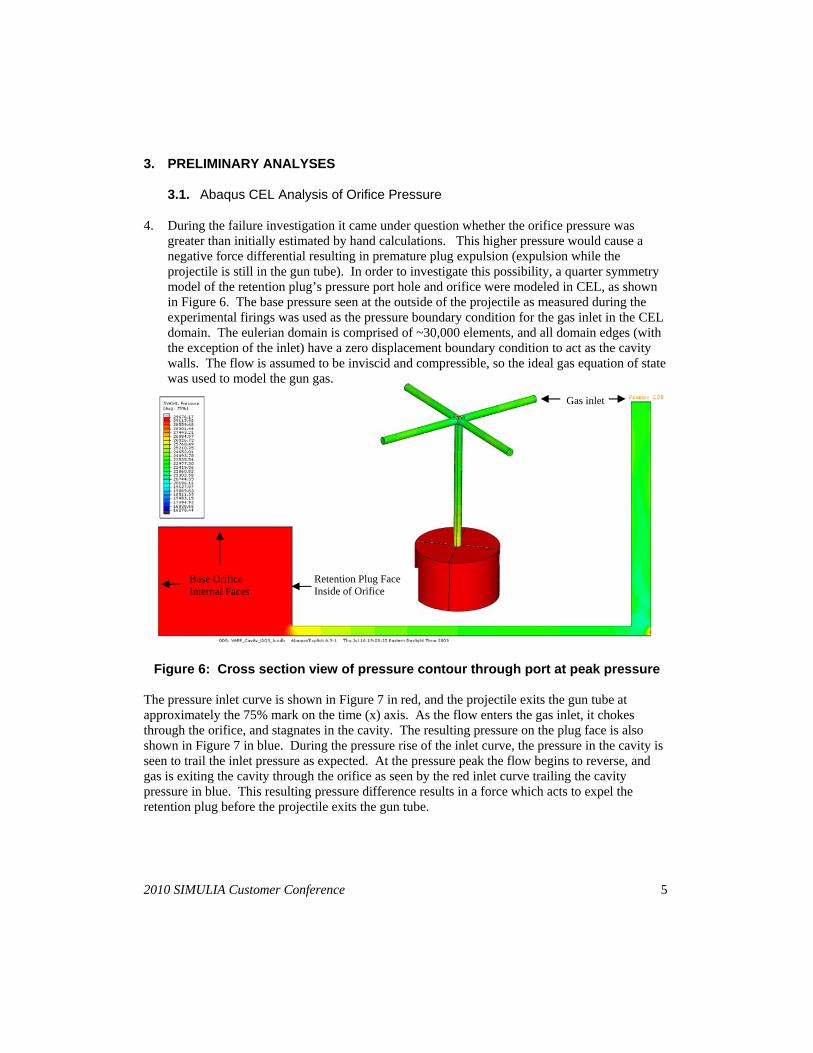
4. During the failure investigation it came under question whether the orifice pressure was greater than initially estimated by hand calculations. This higher pressure would cause a negative force differential resulting in premature plug expulsion (expulsion while the projectile is still in the gun tube). In order to investigate this possibility, a quarter symmetry model of the retention plug’s pressure port hole and orifice were modeled in CEL, as shown in Figure 6. The base pressure seen at the outside of the projectile as measured during the experimental firings was used as the pressure boundary condition for the gas inlet in the CEL domain. The eulerian domain is comprised of ~30,000 elements, and all domain edges (with the exception of the inlet) have a zero displacement boundary condition to act as the cavity walls. The flow is assumed to be inviscid and compressible, so the ideal gas equation of state was used to model the gun gas.
Figure 6: Cross section view of pressure contour through port at peak pressure
The pressure inlet curve is shown in Figure 7 in red, and the projectile exits the gun tube at approximately the 75% mark on the time (x) axis. As the flow enters the gas inlet, it chokes through the orifice, and stagnates in the cavity. The resulting pressure on the plug face is also shown in Figure 7 in blue. During the pressure rise of the inlet curve, the pressure in the cavity is seen to trail the inlet pressure as expected. At the pressure peak the flow begins to reverse, and gas is exiting the cavity through the orifice as seen by the red inlet curve trailing the cavity pressure in blue. This resulting pressure difference results in a force which acts to expel the retention plug before the projectile exits the gun tube.
Base Orifice Internal Faces
Retention Plug Face Inside of Orifice
Gas inlet
6 2010 SIMULIA Customer Conference
0
1 0 0
2 0 0
3 0 0
0 1 2 3 4 5 6 7 8
S t r e s s ( k s i )
S t r a i n ( % )
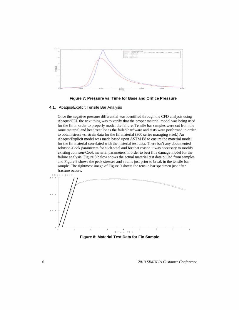
Figure 7: Pressure vs. Time for Base and Orifice Pressure
4.1. Abaqus/Explicit Tensile Bar Analysis
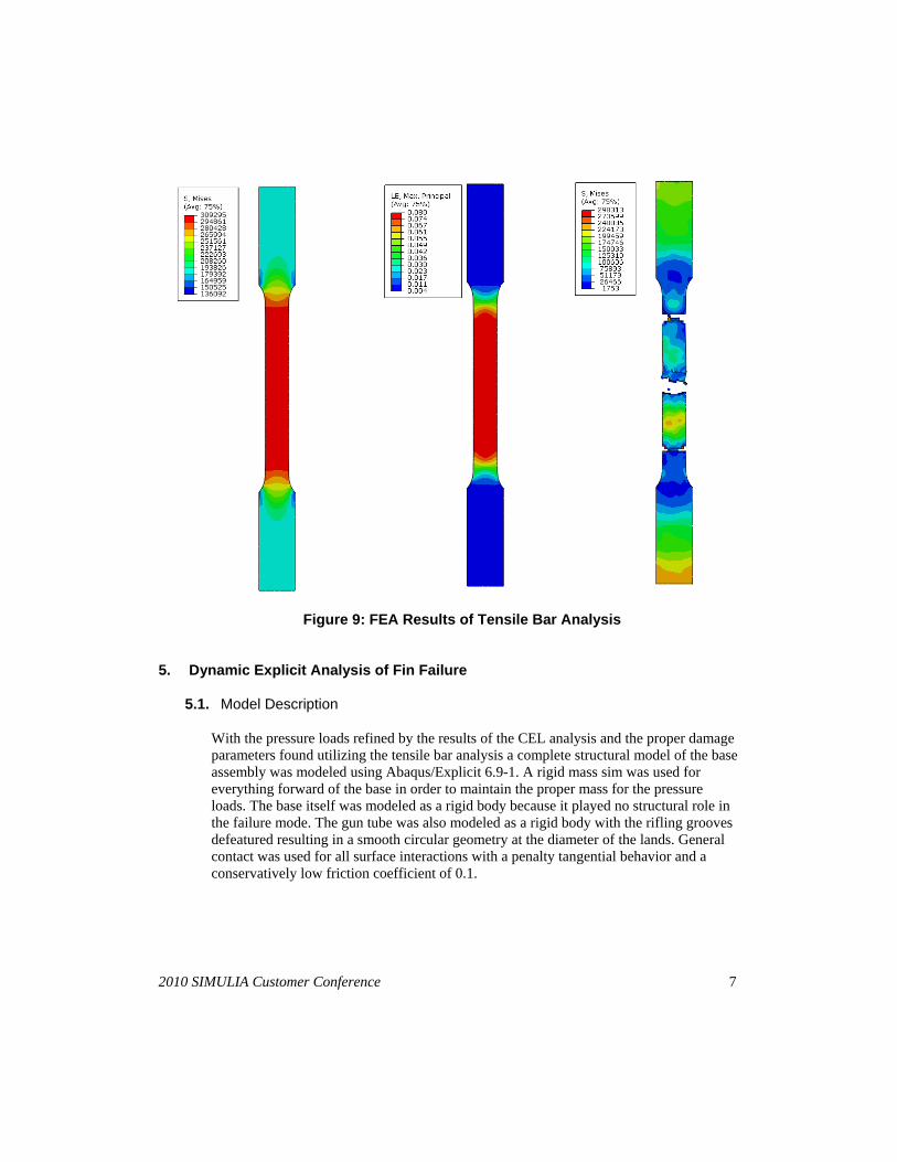
Once the negative pressure differential was identified through the CFD analysis using Abaqus/CEL the next thing was to verify that the proper material model was being used for the fin in order to properly model the failure. Tensile bar samples were cut from the same material and heat treat lot as the failed hardware and tests were performed in order to obtain stress vs. strain data for the fin material (300 series maraging steel.) An Abaqus/Explicit model was made based upon ASTM E8 to ensure the material model for the fin material correlated with the material test data. There isn’t any documented Johnson-Cook parameters for such steel and for that reason it was necessary to modify existing Johnson-Cook material parameters in order to best fit a damage model for the failure analysis. Figure 8 below shows the actual material test data pulled from samples and Figure 9 shows the peak stresses and strains just prior to break in the tensile bar sample. The rightmost image of Figure 9 shows the tensile bar specimen just after fracture occurs.
Figure 8: Material Test Data for Fin Sample
2010 SIMULIA Customer Conference 7
Figure 9: FEA Results of Tensile Bar Analysis 5. Dynamic Explicit Analysis of Fin Failure
5.1. Model Description
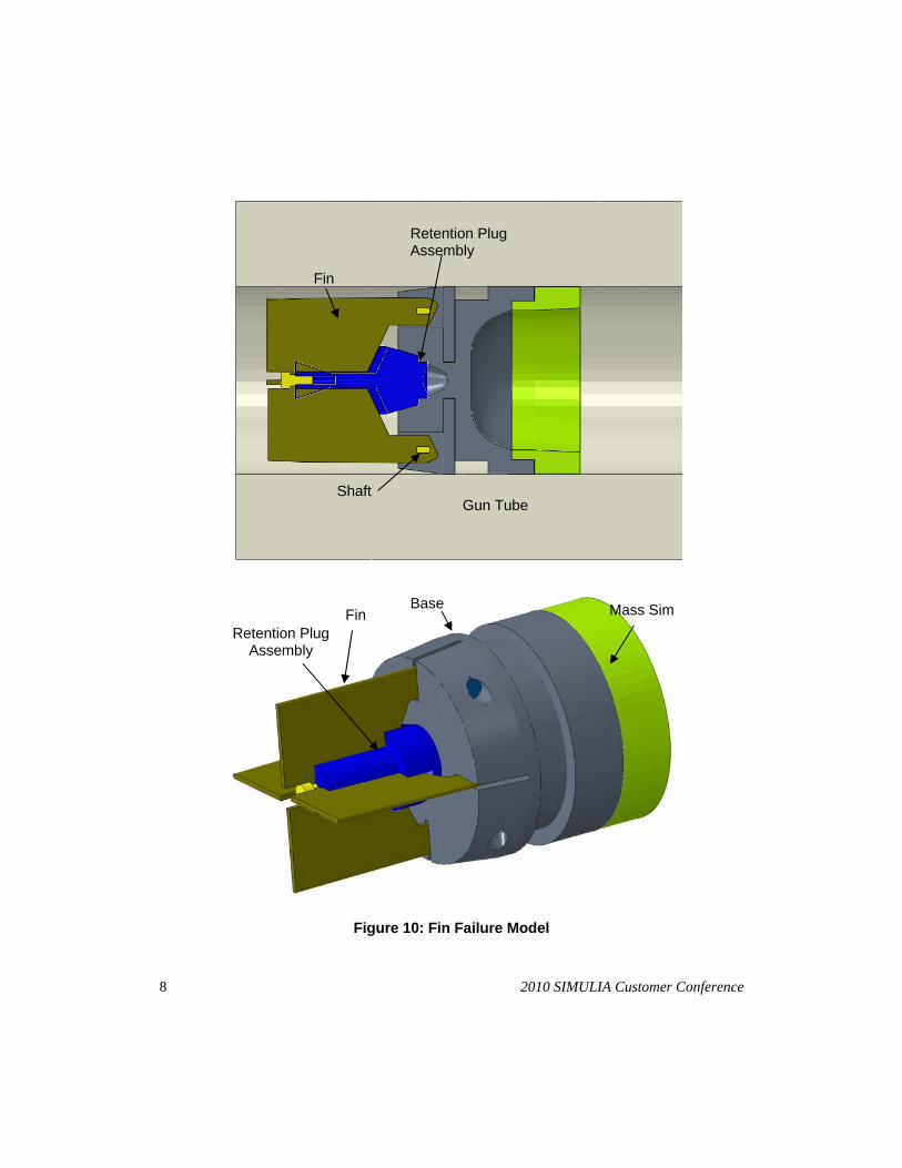
With the pressure loads refined by the results of the CEL analysis and the proper damage parameters found utilizing the tensile bar analysis a complete structural model of the base assembly was modeled using Abaqus/Explicit 6.9-1. A rigid mass sim was used for everything forward of the base in order to maintain the proper mass for the pressure loads. The base itself was modeled as a rigid body because it played no structural role in the failure mode. The gun tube was also modeled as a rigid body with the rifling grooves defeatured resulting in a smooth circular geometry at the diameter of the lands. General contact was used for all surface interactions with a penalty tangential behavior and a conservatively low friction coefficient of 0.1.
8 2010 SIMULIA Customer Conference
Figure 10: Fin Failure Model
Fin Mass Sim Base
Retention Plug Assembly
Gun Tube Shaft
Fin
Retention Plug Assembly
2010 SIMULIA Customer Conference 9
5.2. Mesh
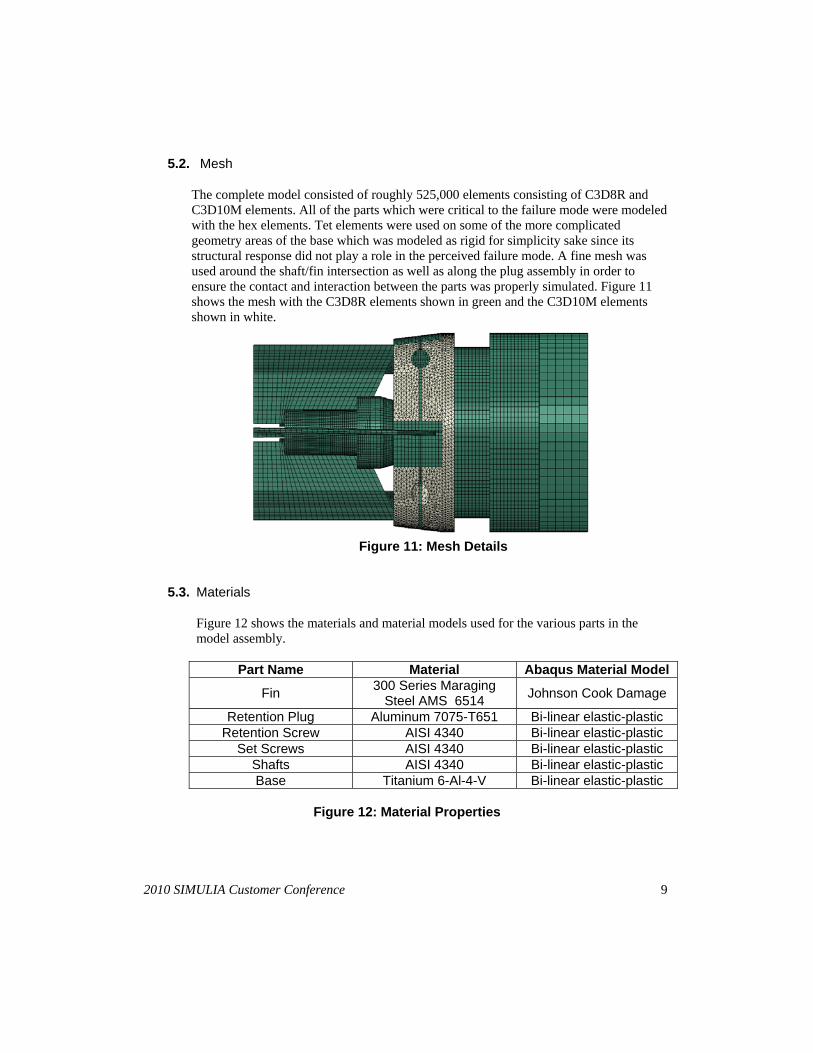
The complete model consisted of roughly 525,000 elements consisting of C3D8R and C3D10M elements. All of the parts which were critical to the failure mode were modeled with the hex elements. Tet elements were used on some of the more complicated geometry areas of the base which was modeled as rigid for simplicity sake since its structural response did not play a role in the perceived failure mode. A fine mesh was used around the shaft/fin intersection as well as along the plug assembly in order to ensure the contact and interaction between the parts was properly simulated. Figure 11 shows the mesh with the C3D8R elements shown in green and the C3D10M elements shown in white.
Figure 11: Mesh Details
5.3. Materials
Figure 12 shows the materials and material models used for the various parts in the model assembly.
Part Name Material Abaqus Material Model
Fin 300 Series Maraging
Steel AMS 6514 Johnson Cook Damage
Retention Plug Aluminum 7075-T651 Bi-linear elastic-plastic Retention Screw AISI 4340 Bi-linear elastic-plastic
Set Screws AISI 4340 Bi-linear elastic-plastic Shafts AISI 4340 Bi-linear elastic-plastic Base Titanium 6-Al-4-V Bi-linear elastic-plastic
Figure 12: Material Properties
10 2010 SIMULIA Customer Conference
5.4. Loads
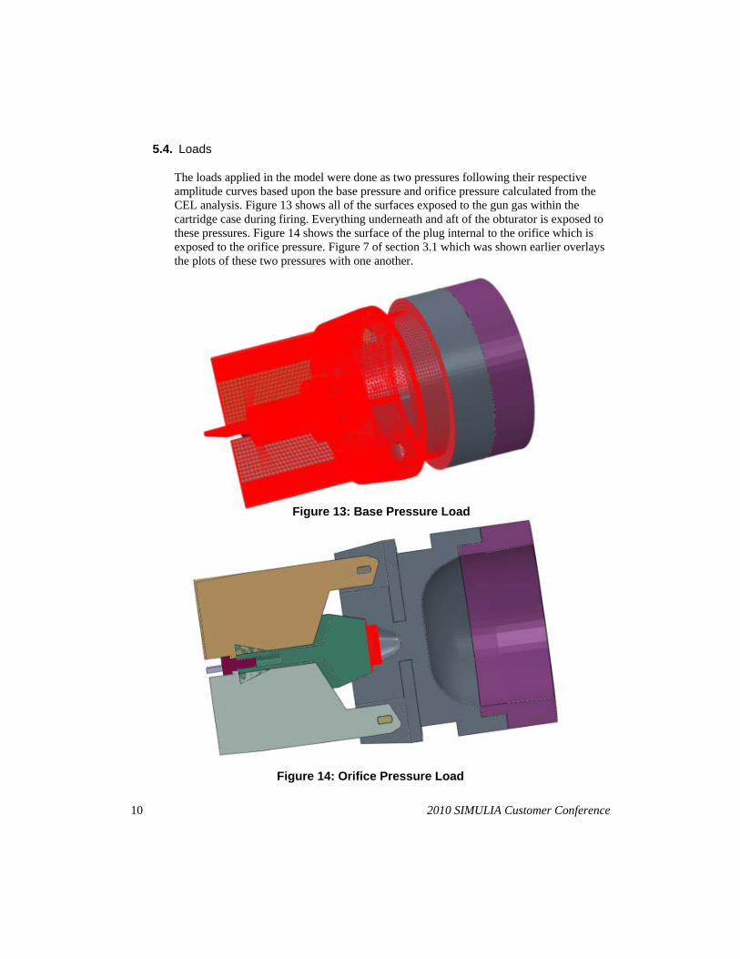
The loads applied in the model were done as two pressures following their respective amplitude curves based upon the base pressure and orifice pressure calculated from the CEL analysis. Figure 13 shows all of the surfaces exposed to the gun gas within the cartridge case during firing. Everything underneath and aft of the obturator is exposed to these pressures. Figure 14 shows the surface of the plug internal to the orifice which is exposed to the orifice pressure. Figure 7 of section 3.1 which was shown earlier overlays the plots of these two pressures with one another.
Figure 13: Base Pressure Load
Figure 14: Orifice Pressure Load
2010 SIMULIA Customer Conference 11
5.5. Boundary Conditions
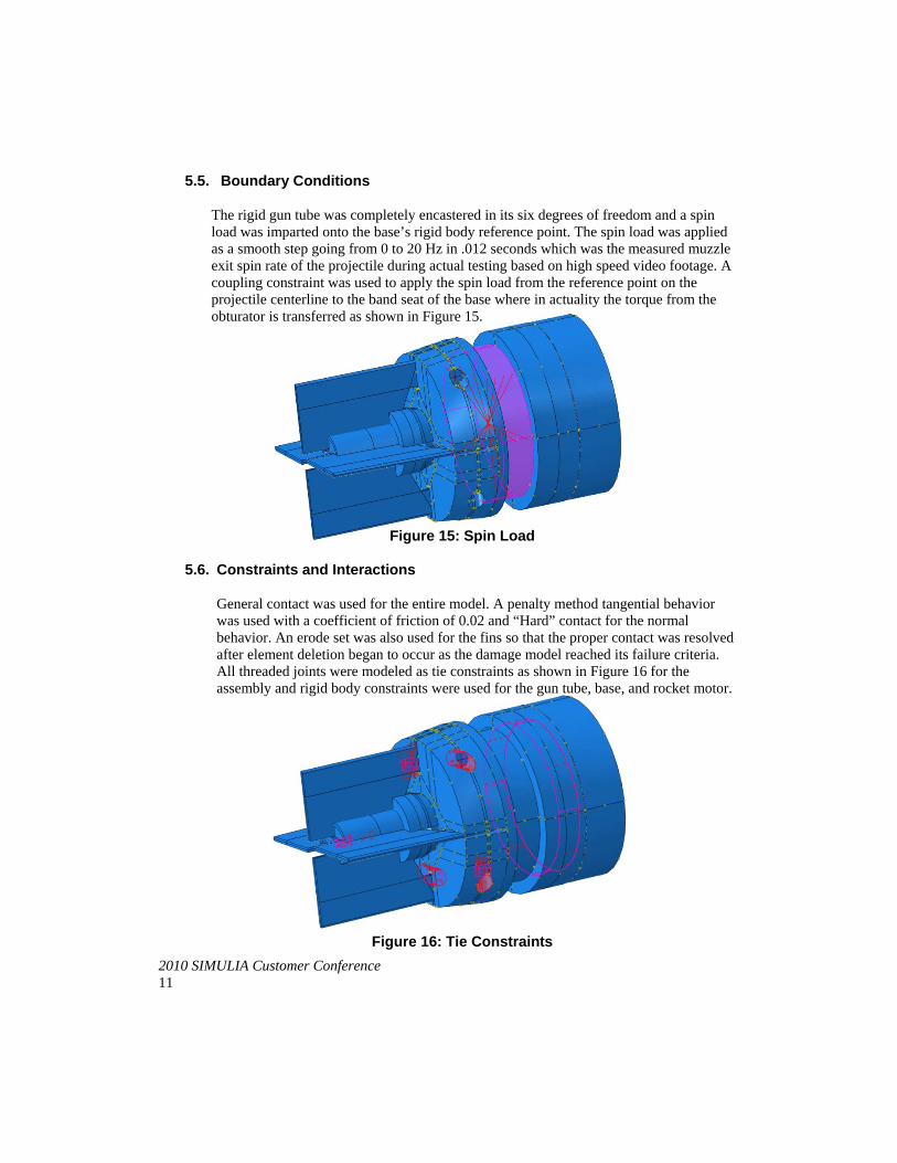
The rigid gun tube was completely encastered in its six degrees of freedom and a spin load was imparted onto the base’s rigid body reference point. The spin load was applied as a smooth step going from 0 to 20 Hz in .012 seconds which was the measured muzzle exit spin rate of the projectile during actual testing based on high speed video footage. A coupling constraint was used to apply the spin load from the reference point on the projectile centerline to the band seat of the base where in actuality the torque from the obturator is transferred as shown in Figure 15.
Figure 15: Spin Load
5.6. Constraints and Interactions
General contact was used for the entire model. A penalty method tangential behavior was used with a coefficient of friction of 0.02 and “Hard” contact for the normal behavior. An erode set was also used for the fins so that the proper contact was resolved after element deletion began to occur as the damage model reached its failure criteria. All threaded joints were modeled as tie constraints as shown in Figure 16 for the assembly and rigid body constraints were used for the gun tube, base, and rocket motor.
Figure 16: Tie Constraints
12 2010 SIMULIA Customer Conference
6. RESULTS
6.1. Results
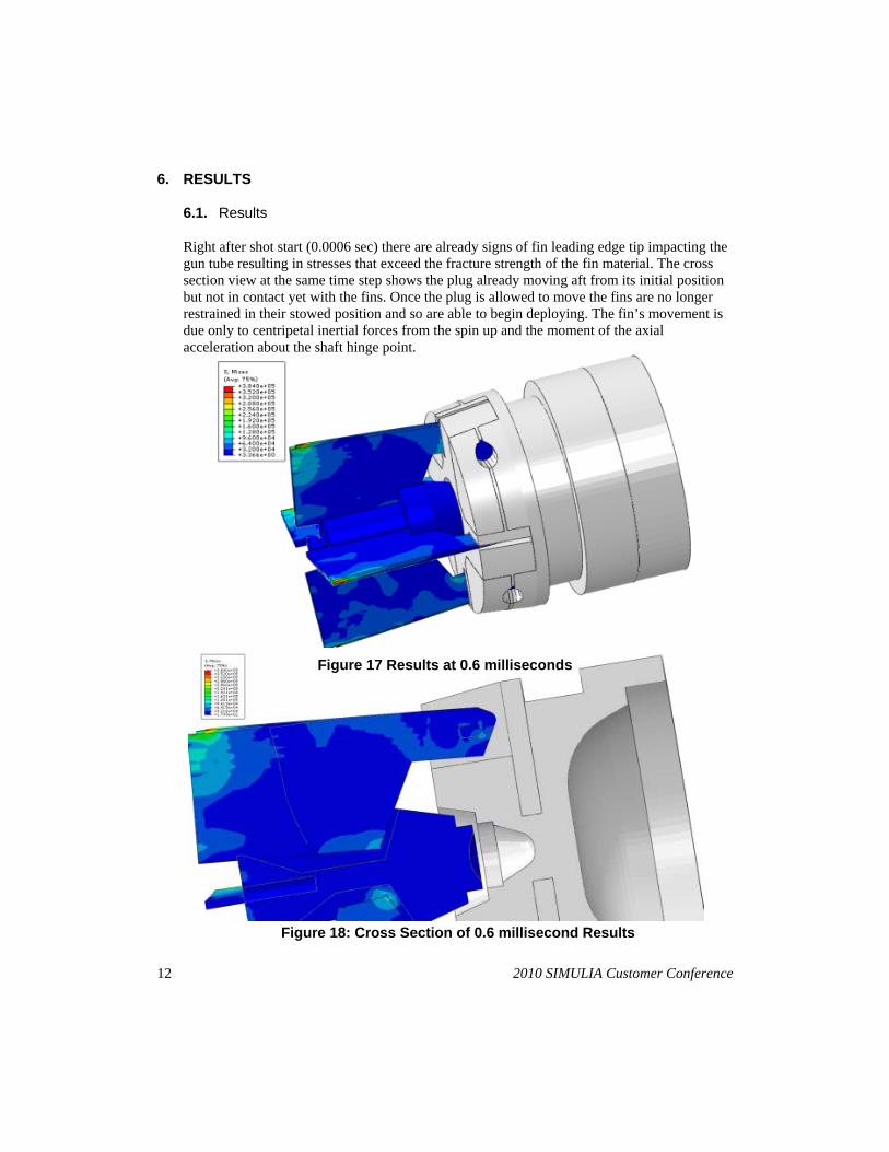
Right after shot start (0.0006 sec) there are already signs of fin leading edge tip impacting the gun tube resulting in stresses that exceed the fracture strength of the fin material. The cross section view at the same time step shows the plug already moving aft from its initial position but not in contact yet with the fins. Once the plug is allowed to move the fins are no longer restrained in their stowed position and so are able to begin deploying. The fin’s movement is due only to centripetal inertial forces from the spin up and the moment of the axial acceleration about the shaft hinge point.
Figure 17 Results at 0.6 milliseconds
Figure 18: Cross Section of 0.6 millisecond Results
2010 SIMULIA Customer Conference 13
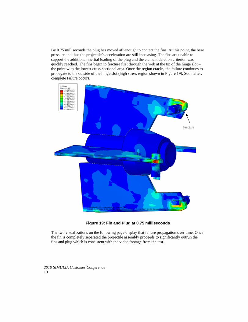
By 0.75 milliseconds the plug has moved aft enough to contact the fins. At this point, the base pressure and thus the projectile’s acceleration are still increasing. The fins are unable to support the additional inertial loading of the plug and the element deletion criterion was quickly reached. The fins begin to fracture first through the web at the tip of the hinge slot – the point with the lowest cross-sectional area. Once the region cracks, the failure continues to propagate to the outside of the hinge slot (high stress region shown in Figure 19). Soon after, complete failure occurs.
Figure 19: Fin and Plug at 0.75 milliseconds
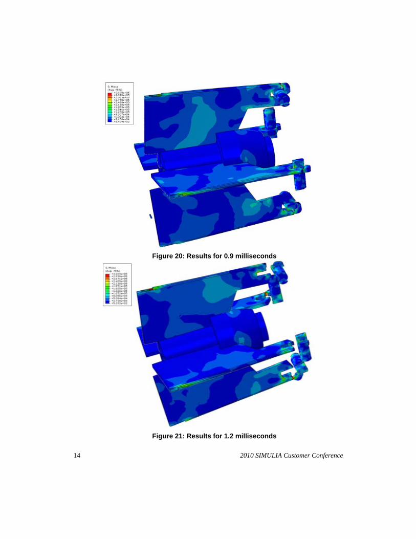
The two visualizations on the following page display that failure propagation over time. Once the fin is completely separated the projectile assembly proceeds to significantly outrun the fins and plug which is consistent with the video footage from the test.
Fracture
14 2010 SIMULIA Customer Conference
Figure 20: Results for 0.9 milliseconds
Figure 21: Results for 1.2 milliseconds
2010 SIMULIA Customer Conference 15
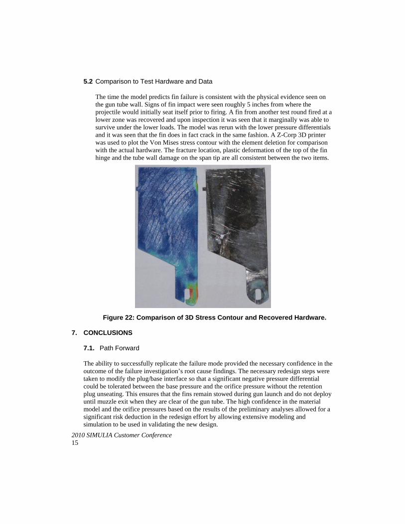
5.2 Comparison to Test Hardware and Data
The time the model predicts fin failure is consistent with the physical evidence seen on the gun tube wall. Signs of fin impact were seen roughly 5 inches from where the projectile would initially seat itself prior to firing. A fin from another test round fired at a lower zone was recovered and upon inspection it was seen that it marginally was able to survive under the lower loads. The model was rerun with the lower pressure differentials and it was seen that the fin does in fact crack in the same fashion. A Z-Corp 3D printer was used to plot the Von Mises stress contour with the element deletion for comparison with the actual hardware. The fracture location, plastic deformation of the top of the fin hinge and the tube wall damage on the span tip are all consistent between the two items.
Figure 22: Comparison of 3D Stress Contour and Recovered Hardware.
7. CONCLUSIONS
7.1. Path Forward
The ability to successfully replicate the failure mode provided the necessary confidence in the outcome of the failure investigation’s root cause findings. The necessary redesign steps were taken to modify the plug/base interface so that a significant negative pressure differential could be tolerated between the base pressure and the orifice pressure without the retention plug unseating. This ensures that the fins remain stowed during gun launch and do not deploy until muzzle exit when they are clear of the gun tube. The high confidence in the material model and the orifice pressures based on the results of the preliminary analyses allowed for a significant risk deduction in the redesign effort by allowing extensive modeling and simulation to be used in validating the new design.
16 2010 SIMULIA Customer Conference
8. REFERENCES
1. Carlucci, P., Mougeotte, C., Huidi, J. “Validation of Abaqus Explicit – CEL for classes of
problems of interest to the US Army” Simulia Customer Conference Proceedings, Providence RI, May 24 – May 27 2010.
2. Johnson, G.R. and Holmquist, T.J., “Test Data and Computational Strength and Fracture Model Constants for 23 Materials Subjected to Large Strains, High Strain Rates, and High Temperatures”, Los Alamos National Laboratory, LA-11463-MS, 1989.
Visit the SIMULIA Resource Center for more customer examples.