Embed Size (px)
Citation preview

IntelliSuite Scripting
Guide Parametric elements and
scripting in IntelliSuite
User Reference
SCRIPTING GUIDE
SCRIPTING GUIDE – IntelliSuite Version 8 Version 8.2/PC Part Number 30-090-105 February 2007 © Copyright IntelliSense Software Corporation 2004, 2005, 2006, 2007 All Rights Reserved. Section 3-10 reproduced from Microsoft VBScript Guide for purely educational purposes and are © Copyright Microsoft, 1997 Printed in the United States of America This manual and the software described within it are the copyright of IntelliSense Software Corporation, with all rights reserved. Restricted Rights Legend Under the copyright laws, neither this manual nor the software that it describes may be copied, in whole or in part, without the written consent of IntelliSense Software Corporation. Use, duplication or disclosure of the Programs is subject to restrictions stated in your software license agreement with IntelliSense Software Corporation. Although due effort has been made to present clear and accurate information, IntelliSense Software Corporation disclaims all warranties with respect to the software or manual, including without limitation warranties of merchantability and fitness for a particular purpose, either expressed or implied. The information in this documentation is subject to change without notice. In no event will IntelliSense Software Corporation be liable for direct, indirect, special, incidental, or consequential damages resulting from use of the software or the documentation. IntelliSuite is a trademark of IntelliSense Software Corporation. RECIPE is a trademark of IntelliSense Software Corporation. Windows NT is a trademark of Microsoft Corporation. Windows 2000 is a trademark of Microsoft Corporation. Patent Number 6,116,766: Fabrication Based Computer Aided Design System Using Virtual Fabrication Techniques Patent Number 6,157,900: Knowledge Based System and Method for Determining Material Properties from Fabrication and Operating Parameters
2
SCRIPTING GUIDE
Table of contents 1 How to Script ...................................................................................................................... 9
1.1 Official Scripting Language........................................................................................ 9 1.2 Using other scripting languages............................................................................... 9 1.3 What is VBScript? ....................................................................................................10
1.3.1 Easy to Use and Learn.................................................................................................10 1.3.2 ActiveX Scripting............................................................................................................10
1.4 VBScript Data Types ...............................................................................................11 1.4.1 What Are VBScript Data Types?...............................................................................11 1.4.2 Variant Subtypes............................................................................................................11
1.5 VBScript Variables....................................................................................................14 1.5.1 What Is a Variable?......................................................................................................14 1.5.2 Declaring Variables .......................................................................................................14 1.5.3 Naming Restrictions......................................................................................................14 1.5.4 Scope and Lifetime of Variables................................................................................14 1.5.5 Assigning Values to Variables .....................................................................................15 1.5.6 Scalar Variables and Array Variables.......................................................................15
1.6 VBScript Constants..................................................................................................17 1.6.1 What Is a Constant? ....................................................................................................17 1.6.2 Creating Constants........................................................................................................17
1.7 VBScript Operators.................................................................................................18 1.7.1 Operator Precedence....................................................................................................18
1.8 Using Conditional Statements ...............................................................................20 1.8.1 Controlling Program Execution ..................................................................................20 1.8.2 Making Decisions Using If...Then...Else ...................................................................20 1.8.3 Running Statements if a Condition is True.............................................................20 1.8.4 Running Certain Statements if a Condition is True and Running Others if a Condition is False ...............................................................................................................................21 1.8.5 Deciding Between Several Alternatives....................................................................21 1.8.6 Making Decisions with Select Case..........................................................................21
1.9 Looping Through Code ..........................................................................................23 1.9.1 Using Loops to Repeat Code......................................................................................23 1.9.2 Using Do Loops..............................................................................................................23 1.9.3 Repeating Statements While a Condition is True ................................................23 1.9.4 Repeating a Statement Until a Condition Becomes True...................................24 1.9.5 Exiting a Do...Loop Statement from Inside the Loop...........................................24 1.9.6 Using While...Wend......................................................................................................25
3
SCRIPTING GUIDE
1.9.7 Using For...Next............................................................................................................. 25 1.9.8 Using For Each...Next .................................................................................................. 26
1.10 VBScript Procedures .......................................................................................... 27 1.10.1 Kinds of Procedures...................................................................................................... 27 1.10.2 Sub Procedures.............................................................................................................. 27 1.10.3 Function Procedures ..................................................................................................... 27 1.10.4 Getting Data into and out of Procedures ............................................................... 28 1.10.5 Using Sub and Function Procedures in Code ........................................................ 28
1.11 Your first script ................................................................................................... 29 1.11.1 Step-Wise Description of the Bi-Morph Script ..................................................... 29 1.11.2 Comment Statements.................................................................................................. 29 1.11.3 Declaration of Variables.............................................................................................. 29 1.11.4 Assign Values to Variables.......................................................................................... 30 1.11.5 Body of the Script ......................................................................................................... 31
2 Active MEMS Elements .................................................................................................... 39 2.1 Linear Comb Drive Element ................................................................................. 39 2.2 Linear Side Drive Elements.................................................................................... 42 2.3 Unidirectional Rotary Comb Drive Elements-1................................................ 45 2.4 Unidirectional Rotary Comb Drive-2.................................................................. 48 2.5 Bi-directional Rotary Comb Drive Elements ..................................................... 51 2.6 Harmonic Side Drive Elements............................................................................. 54 2.7 Rotary Side Drive Elements .................................................................................. 57 2.8 Folded Spring ............................................................................................................ 60
3 Passive MEMS Elements................................................................................................... 63 3.1 Journal Bearing Element ......................................................................................... 63 3.2 Linear Crab Leg Suspension Elements-1............................................................. 66 3.3 Linear Crab Leg Suspension Elements-2............................................................. 69 3.4 Linear Folded Beam Suspension Elements ......................................................... 72
4 MEMS Packaging Elements .............................................................................................. 77 4.1 Dual Inline Pin Package ........................................................................................... 77 4.2 Small Outline IC Package ....................................................................................... 80 4.3 Quad Flatpack Package_Gull-Winged Pins......................................................... 83
4
SCRIPTING GUIDE
4.4 Quad Flatpack Package ...........................................................................................86 4.5 To Can........................................................................................................................89 4.6 Perforated Rectangular Plate .................................................................................92
5 Electrical and mechanical test elements .......................................................................95 5.1 Area-Perimeter Dielectric Isolation Test Structure (APTEST)......................95 5.2 Crossover Test Structure Element ......................................................................98 5.3 Crossover Test Structure Element ....................................................................101 5.4 Euler Column (Doubly supported Beam) .........................................................104 5.5 Array of Euler Column - Doubly Supported Beam.........................................107 5.6 Guckel Ring Test Structure Element .................................................................110 5.7 Array of Guckel Ring.............................................................................................113 5.8 Multilayer Pad Element (MPE) .............................................................................116 5.9 Rectangular Coil .....................................................................................................119
6 MEMS Stress Elements ...................................................................................................123 6.1 Bent Beam................................................................................................................123 6.2 Vernier Frame.........................................................................................................126
7 Miscellaneous MEMS Elements.....................................................................................129 7.1 Meter ........................................................................................................................129 7.2 Staple ........................................................................................................................131 7.3 Bearing......................................................................................................................133 7.4 Vertical Support .....................................................................................................135 7.5 Capacitor .................................................................................................................138
8 Beam and Truss Elements .............................................................................................141 8.1 Perforated Rectangular Beam..............................................................................141 8.2 Rectangular Perforated Truss Element..............................................................143 8.3 Diamond Truss Element .......................................................................................145
9 Heatuators........................................................................................................................149 9.1 Bi-Morph ..................................................................................................................149
5
SCRIPTING GUIDE
9.2 Multi Bi-Morph ....................................................................................................... 152 9.3 Vertical Heatuator................................................................................................. 154 9.4 Tiptuator.................................................................................................................. 156
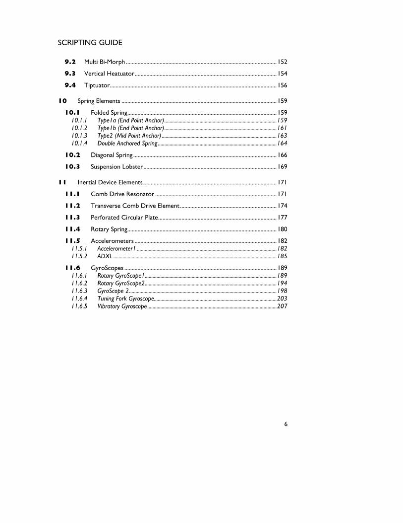
10 Spring Elements .......................................................................................................... 159 10.1 Folded Spring...................................................................................................... 159
10.1.1 Type1a (End Point Anchor)......................................................................................159 10.1.2 Type1b (End Point Anchor)......................................................................................161 10.1.3 Type2 (Mid Point Anchor) ........................................................................................163 10.1.4 Double Anchored Spring ...........................................................................................164
10.2 Diagonal Spring .................................................................................................. 166 10.3 Suspension Lobster........................................................................................... 169
11 Inertial Device Elements ........................................................................................... 171 11.1 Comb Drive Resonator ................................................................................... 171 11.2 Transverse Comb Drive Element .................................................................. 174 11.3 Perforated Circular Plate................................................................................. 177 11.4 Rotary Spring...................................................................................................... 180 11.5 Accelerometers ................................................................................................. 182
11.5.1 Accelerometer1 ...........................................................................................................182 11.5.2 ADXL .............................................................................................................................185
11.6 GyroScopes ........................................................................................................ 189 11.6.1 Rotary GyroScope1.....................................................................................................189 11.6.2 Rotary GyroScope2.....................................................................................................194 11.6.3 GyroScope 2.................................................................................................................198 11.6.4 Tuning Fork Gyroscope..............................................................................................203 11.6.5 Vibratory Gyroscope...................................................................................................207
6

SCRIPTING GUIDE
Learning to Script
Scripting guide to IntelliMask
7

SCRIPTING GUIDE
8
SCRIPTING GUIDE
How to Script 1.1 Official Scripting Language The officially supported scripting language for IntelliMask is VBScript. While other languages can be used, IntelliSense does not provide technical assistance for using other scripting languages. IntelliMask using a Windows technology called Windows Scripting Host (WSH) to support scripting. While WSH can be used with other languages, we do not provide official support for other languages. 1.2 Using other scripting languages You can use other scripting languages such as Perl or Tcl/Tk or Python with IntelliMask. However, IntelliSense does not officially support other languages. There are excellent tutorials online for using other languages with Windows Scripting Host. For example if you wish to use Perl take a look at: < http://pages.infinit.net/che/perlwsh/perlwsh0.html> A commercial Perl IDE for Windows can be bought from Active State < http://www.activestate.com/>. You can also download a free version of ActivePerl from Active State. For more information on using ActivePerl with IntelliMask please see: <http://aspn.activestate.com/ASPN/docs/ActivePerl/Windows/WindowsScriptHost.html> Python users can take a look at examples at ASPN ActiveScript also provides ActivePython which can be used for scripting IntelliMask in Python. <http://aspn.activestate.com/ASPN/Cookbook/Python/Recipe/65107 or consult the newsgroup news:comp.lang.python> Tcl/Tk and Rexx users can take a look at < http://labmice.techtarget.com/scripting/WSH.htm> for more information.
9
SCRIPTING GUIDE
1.3 What is VBScript? Sections 1.3.1 through 1.10 are excerpts from Microsoft Developer Network and are © Microsoft Corp.. More information on scripting can be found at: <http://msdn.microsoft.com/scripting/> For a convenient Online Reference Guide see: < http://msdn.microsoft.com/library/default.asp?url=/library/en-us/script56/html/vtoriVBScript.asp > Microsoft Visual Basic Scripting Edition, the newest member of the Visual Basic family of programming languages, brings active scripting to a wide variety of environments, including Web client scripting in Microsoft Internet Explorer and Web server scripting in Microsoft Internet Information Server. 1.3.1 Easy to Use and Learn If you already know Visual Basic or Visual Basic for Applications, VBScript will be very familiar. Even if you don't know Visual Basic, once you learn VBScript, you're on your way to programming with the whole family of Visual Basic languages. Although you can learn about VBScript in just these few Web pages, they don't teach you how to program. To get started programming, take a look at Step by Step books available from Microsoft Press. 1.3.2 ActiveX Scripting VBScript talks to host applications using ActiveX™ Scripting. With ActiveX Scripting, browsers and other host applications don't require special integration code for each scripting component. ActiveX Scripting enables a host to compile scripts, obtain and call entry points, and manage the namespace available to the developer. With ActiveX Scripting, language vendors can create standard language run times for scripting. Microsoft will provide run-time support for VBScript. Microsoft is working with various Internet groups to define the ActiveX Scripting standard so that scripting engines can be interchangeable. ActiveX Scripting is used in Microsoft® Internet Explorer and in Microsoft® Internet Information Server.
10
SCRIPTING GUIDE
1.4 VBScript Data Types 1.4.1 What Are VBScript Data Types? VBScript has only one data type called a Variant. A Variant is a special kind of data type that can contain different kinds of information, depending on how it's used. Because Variant is the only data type in VBScript, it's also the data type returned by all functions in VBScript. At its simplest, a Variant can contain either numeric or string information. A Variant behaves as a number when you use it in a numeric context and as a string when you use it in a string context. That is, if you're working with data that looks like numbers, VBScript assumes that it is numbers and does the thing that is most appropriate for numbers. Similarly, if you're working with data that can only be string data, VBScript treats it as string data. Of course, you can always make numbers behave as strings by enclosing them in quotation marks (" "). 1.4.2 Variant Subtypes Beyond the simple numeric or string classifications, a Variant can make further distinctions about the specific nature of numeric information. For example, you can have numeric information that represents a date or a time. When used with other date or time data, the result is always expressed as a date or a time. Of course, you can also have a rich variety of numeric information ranging in size from Boolean values to huge floating-point numbers. These different categories of information that can be contained in a Variant are called subtypes. Most of the time, you can just put the kind of data you want in a Variant, and the Variant behaves in a way that is most appropriate for the data it contains. The following table shows the subtypes of data that a Variant can contain. Empty Variant is uninitialized. Value is 0 for numeric variables or a zero-length string ("") for string variables. Null Variant intentionally contains no valid data. Boolean
11

SCRIPTING GUIDE
Contains either True or False. Byte Contains integer in the range 0 to 255. Integer Contains integer in the range -32,768 to 32,767. Currency -922,337,203,685,477.5808 to 922,337,203,685,477.5807. Long Contains integer in the range -2,147,483,648 to 2,147,483,647. Single Contains a single-precision, floating-point number in the range -3.402823E38 to -1.401298E-45 for negative values; 1.401298E-45 to 3.402823E38 for positive values. Double Contains a double-precision, floating-point number in the range -1.79769313486232E308 to -4.94065645841247E-324 for negative values; 4.94065645841247E-324 to 1.79769313486232E308 for positive values. Date (Time) Contains a number that represents a date between January 1, 100 to December 31, 9999. String Contains a variable-length string that can be up to approximately 2 billion characters in length. Object Contains an object. Error Contains an error number.
12

SCRIPTING GUIDE
You can use conversion functions to convert data from one subtype to another. In addition, the VarType function returns information about how your data is stored within a Variant
13
SCRIPTING GUIDE
1.5 VBScript Variables 1.5.1 What Is a Variable? A variable is a convenient placeholder that refers to a computer memory location where you can store program information that may change during the time your script is running. For example, you might create a variable called ClickCount to store the number of times a user clicks an object on a particular Web page. Where the variable is stored in computer memory is unimportant. What's important is that you only have to refer to a variable by name to see its value or to change its value. In VBScript, variables are always of one fundamental data type, Variant. 1.5.2 Declaring Variables You declare variables explicitly in your script using the Dim statement, the Public statement, and the Private statement. For example: D You declare multiple variables by separating each variable name with a comma. For example:
im DegreesFahrenheit
Dim Top, Bottom, Left, Right You can also declare a variable implicitly by simply using its name in your script. That's not generally a good practice because you could misspell the variable name in one or more places, causing unexpected results when your script is run. For that reason, the Option Explicit statement is available to require explicit declaration of all variables. The Option Explicit statement should be the first statement in your script. 1.5.3 Naming Restrictions Variable names follow the standard rules for naming anything in VBScript. A variable name: • Must begin with an alphabetic character. • Cannot contain an embedded period. • Must not exceed 255 characters. • Must be unique in the scope in which it is declared. 1.5.4 Scope and Lifetime of Variables A variable's scope is determined by where you declare it. When you declare a variable within a procedure, only code within that procedure can access or change the value of that variable. It has local scope and is called a procedure-level variable. If you declare a variable outside a procedure, you make it recognizable to all the procedures in your script. This is a script-level variable, and it has script-level scope. How long a variable exists is its lifetime. The lifetime of a script-level variable extends from the time it's declared until the time the script is finished running. At
14
SCRIPTING GUIDE
procedure level, a variable exists only as long as you are in the procedure. When the procedure exits, the variable is destroyed. Local variables are ideal as temporary storage space when a procedure is executing. You can have local variables of the same name in several different procedures because each is recognized only by the procedure in which it is declared. 1.5.5 Assigning Values to Variables Values are assigned to variables creating an expression as follows: the variable is on the left side of the expression and the value you want to assign to the variable is on the right. For example: B = 200
1.5.6 Scalar Variables and Array Variables Much of the time, you just want to assign a single value to a variable you've declared. A variable containing a single value is a scalar variable. Other times, it's convenient to assign more than one related value to a single variable. Then you can create a variable that can contain a series of values. This is called an array variable. Array variables and scalar variables are declared in the same way, except that the declaration of an array variable uses parentheses ( ) following the variable name. In the following example, a single-dimension array containing 11 elements is declared: Dim A(10)
Although the number shown in the parentheses is 10, all arrays in VBScript are zero-based, so this array actually contains 11 elements. In a zero-based array, the number of array elements is always the number shown in parentheses plus one. This kind of array is called a fixed-size array. You assign data to each of the elements of the array using an index into the array. Beginning at zero and ending at 10, data can be assigned to the elements of an array as follows: A(0) = 256 A(1) = 324 A(2) = 100 . . . A(10) = 55
Similarly, the data can be retrieved from any element using an index into the particular array element you want. For example: . . . SomeVariable = A(8) . . . Arrays aren't limited to a single dimension. You can have as many as 60 dimensions, although most people can't comprehend more than three or four dimensions. Multiple dimensions are declared by separating an array's size numbers in the parentheses with
15
SCRIPTING GUIDE
commas. In the following example, the MyTable variable is a two-dimensional array consisting of 6 rows and 11 columns: Dim MyTable(5, 10)
In a two-dimensional array, the first number is always the number of rows; the second number is the number of columns. You can also declare an array whose size changes during the time your script is running. This is called a dynamic array. The array is initially declared within a procedure using either the Dim statement or using the ReDim statement. However, for a dynamic array, no size or number of dimensions is placed inside the parentheses.
r example: Fo Dim MyArray() ReDim AnotherArray() To use a dynamic array, you must subsequently use ReDim to determine the number of dimensions and the size of each dmension. In the following example, ReDim sets the initial size of the dynamic array to 25. A subsequent ReDim statement resizes the array to 30, but uses the Preserve keyword to preserve the contents of the array as
resizing takes place. the ReDim MyArray(25) . . . ReDim Preserve MyArray(30)
There is no limit to the number of times you can resize a dynamic array, but you should know that if you make an array smaller than it was, you lose the data in the eliminated elements.
16
SCRIPTING GUIDE
1.6 VBScript Constants 1.6.1 What Is a Constant? A constant is a meaningful name that takes the place of a number or string and never changes. VBScript defines a number of intrinsic constants. You can get information about these intrinsic constants from the VBScript Language Reference. 1.6.2 Creating Constants You create user-defined constants in VBScript using the Const statement. Using the Const statement, you can create string or numeric constants with meaningful names and assign them literal values. For example: Const MyString = "This is my string." Const MyAge = 49
Note that the string literal is enclosed in quotation marks (" "). Quotation marks are the most obvious way to differentiate string values from numeric values. Date literals and time literals are represented by enclosing them in number signs (#). For example: Const CutoffDate = #6-1-97#
You may want to adopt a naming scheme to differentiate constants from variables. This will prevent you from trying to reassign constant values while your script is running. For example, you might want to use a "vb" or "con" prefix on your constant names, or you might name your constants in all capital letters. Differentiating constants from variables eliminates confusion as you develop more complex scripts.
17
SCRIPTING GUIDE
1.7 VBScript Operators VBScript has a full range of operators, including arithmetic operators, comparison operators, concatenation operators, and logical operators. 1.7.1 Operator Precedence When several operations occur in an expression, each part is evaluated and resolved in a predetermined order called operator precedence. You can use parentheses to override the order of precedence and force some parts of an expression to be evaluated before others. Operations within parentheses are always performed before those outside. Within parentheses, however, standard operator precedence is maintained. When expressions contain operators from more than one category, arithmetic operators are evaluated first, comparison operators are evaluated next, and logical operators are evaluated last. Comparison operators all have equal precedence; that is, they are evaluated in the left-to-right order in which they appear. Arithmetic and logical operators are evaluated in the following order of precedence.
When multiplication and division occur together in an expression, each operation is evaluated as it occurs from left to right. Likewise, when addition and subtraction occur
Arithmetic Comparison Logical Description Symbol Description Symbol Description Symbol
Exponentiation ^ Equality = Logical negation
Not
Unary negation - Inequality <> Logical conjunction
And
Multiplication * Less than < Logical disjunction
Or
Division / Greater than > Logical exclusion
Xor
Integer division \ Less than or equal to
<= Logical equivalence
Eqv
Modulus arithmetic
Mod Greater than or equal to
>= Logical implication
Imp
Addition + Object equivalence
Is
Subtraction - String
concatenation &
18

SCRIPTING GUIDE
together in an expression, each operation is evaluated in order of appearance from left to right. The string concatenation (&) operator is not an arithmetic operator, but in precedence it does fall after all arithmetic operators and before all comparison operators. The Is operator is an object reference comparison operator. It does not compare objects or their values; it checks only to determine if two object references refer to the same object.
19
SCRIPTING GUIDE
1.8 Using Conditional Statements 1.8.1 Controlling Program Execution You can control the flow of your script with conditional statements and looping statements. Using conditional statements, you can write VBScript code that makes decisions and repeats actions. The following conditional statements are available in VBScript: • If...Then...Else statement • Select Case statement 1.8.2 Making Decisions Using If...Then...Else The If...Then...Else statement is used to evaluate whether a condition is True or False and, depending on the result, to specify one or more statements to run. Usually the condition is an expression that uses a comparison operator to compare one value or variable with another. For information about comparison operators, see Comparison Operators. If...Then...Else statements can be nested to as many levels as you need. 1.8.3 Running Statements if a Condition is True To run only one statement when a condition is True, use the single-line syntax for the If...Then...Else statement. The following example shows the single-line syntax. Notice that this example omits the Else keyword. Sub FixDate() Dim myDate myDate = #2/13/95# If myDate < Now Then myDate = Now End Sub
To run more than one line of code, you must use the multiple-line (or block) syntax. This syntax includes the End If statement, as shown in the following example: Sub AlertUser(value) If value = 0 Then AlertLabel.ForeColor = vbRed AlertLabel.Font.Bold = True AlertLabel.Font.Italic = True End If End Sub
20
SCRIPTING GUIDE
1.8.4 Running Certain Statements if a Condition is True and Running Others if a Condition is False
You can use an If...Then...Else statement to define two blocks of executable statements: one block to run if the condition is True, the other block to run if the condition is False. Sub AlertUser(value) If value = 0 Then AlertLabel.ForeColor = vbRed AlertLabel.Font.Bold = True AlertLabel.Font.Italic = True Else AlertLabel.Forecolor = vbBlack AlertLabel.Font.Bold = False AlertLabel.Font.Italic = False End If End Sub
1.8.5 Deciding Between Several Alternatives A variation on the If...Then...Else statement allows you to choose from several alternatives. Adding ElseIf clauses expands the functionality of the If...Then...Else statement so you can control program flow based on different possibilities. For example: Sub ReportValue(value) If value = 0 Then MsgBox value ElseIf value = 1 Then MsgBox value ElseIf value = 2 then Msgbox value Else Msgbox "Value out of range!" End If
You can add as many ElseIf clauses as you need to provide alternative choices. Extensive use of the ElseIf clauses often becomes cumbersome. A better way to choose between several alternatives is the Select Case statement. 1.8.6 Making Decisions with Select Case The Select Case structure provides an alternative to If...Then...ElseIf for selectively executing one block of statements from among multiple blocks of statements. A Select Case statement provides capability similar to the If...Then...Else statement, but it makes code more efficient and readable.
21
SCRIPTING GUIDE
A Select Case structure works with a single test expression that is evaluated once, at the top of the structure. The result of the expression is then compared with the values for each Case in the structure. If there is a match, the block of statements associated with that Case is executed: Select Case Document.Form1.CardType.Options(SelectedIndex).Text Case "MasterCard" DisplayMCLogo ValidateMCAccount Case "Visa" DisplayVisaLogo ValidateVisaAccount Case "American Express" DisplayAMEXCOLogo ValidateAMEXCOAccount Case Else DisplayUnknownImage PromptAgain End Select
Notice that the Select Case structure evaluates an expression once at the top of the structure. In contrast, the If...Then...ElseIf structure can evaluate a different expression for each ElseIf statement. You can replace an If...Then...ElseIf structure with a Select Case structure only if each ElseIf statement evaluates the same expression.
22
SCRIPTING GUIDE
1.9 Looping Through Code 1.9.1 Using Loops to Repeat Code Looping allows you to run a group of statements repeatedly. Some loops repeat statements until a condition is False; others repeat statements until a condition is True. There are also loops that repeat statements a specific number of times. The following looping statements are available in VBScript: • Do...Loop: Loops while or until a condition is True. • While...Wend: Loops while a condition is True. • For...Next: Uses a counter to run statements a specified number of times. • For Each...Next: Repeats a group of statements for each item in a collection or each element of an array. 1.9.2 Using Do Loops You can use Do...Loop statements to run a block of statements an indefinite number of times. The statements are repeated either while a condition is True or until a condition becomes True. 1.9.3 Repeating Statements While a Condition is True Use the While keyword to check a condition in a Do...Loop statement. You can check the condition before you enter the loop (as shown in the following ChkFirstWhile example), or you can check it after the loop has run at least once (as shown in the ChkLastWhile example). In the ChkFirstWhile procedure, if myNum is set to 9 instead of 20, the statements inside the loop will never run. In the ChkLastWhile procedure, the statements inside the loop run only once because the condition is already False. Sub ChkFirstWhile() Dim counter, myNum counter = 0 myNum = 20 Do While myNum > 10 myNum = myNum - 1 counter = counter + 1 Loop MsgBox "The loop made " & counter & " repetitions." End Sub Sub ChkLastWhile() Dim counter, myNum counter = 0 myNum = 9 Do
23
SCRIPTING GUIDE
myNum = myNum - 1 counter = counter + 1 Loop While myNum > 10 MsgBox "The loop made " & counter & " repetitions." End Sub 1.9.4 Repeating a Statement Until a Condition Becomes True You can use the Until keyword in two ways to check a condition in a Do...Loop statement. You can check the condition before you enter the loop (as shown in the following ChkFirstUntil example), or you can check it after the loop has run at least once (as shown in the ChkLastUntil example). As long as the condition is False, the looping occurs. Sub ChkFirstUntil() Dim counter, myNum counter = 0 myNum = 20 Do Until myNum = 10 myNum = myNum - 1 counter = counter + 1 Loop MsgBox "The loop made " & counter & " repetitions." End Sub Sub ChkLastUntil() Dim counter, myNum counter = 0 myNum = 1 Do myNum = myNum + 1 counter = counter + 1 Loop Until myNum = 10 MsgBox "The loop made " & counter & " repetitions." End Sub
1.9.5 Exiting a Do...Loop Statement from Inside the Loop You can exit a Do...Loop by using the Exit Do statement. Because you usually want to exit only in certain situations, such as to avoid an endless loop, you should use the Exit Do statement in the True statement block of an If...Then...Else statement. If the condition is False, the loop runs as usual. In the following example, myNum is assigned a value that creates an endless loop. The If...Then...Else statement checks for this condition, preventing the endless repetition. Sub ExitExample() Dim counter, myNum
24
SCRIPTING GUIDE
counter = 0 myNum = 9 Do Until myNum = 10 myNum = myNum - 1 counter = counter + 1 If myNum < 10 Then Exit Do Loop MsgBox "The loop made " & counter & " repetitions." End Sub 1.9.6 Using While...Wend The While...Wend statement is provided in VBScript for those who are familiar with its usage. However, because of the lack of flexibility in While...Wend, it is recommended that you use Do...Loop instead. 1.9.7 Using For...Next You can use For...Next statements to run a block of statements a specific number of times. For loops, use a counter variable whose value is increased or decreased with each repetition of the loop. For example, the following procedure causes a procedure called MyProc to execute 50 times. The For statement specifies the counter variable x and its start and end values. The Next statement increments the counter variable by 1. Sub DoMyProc50Times() Dim x For x = 1 To 50 MyProc Next End Sub Using the Step keyword, you can increase or decrease the counter variable by the value you specify. In the following example, the counter variable j is incremented by 2 each time the loop repeats. When the loop is finished, total is the sum of 2, 4, 6, 8, and 10. Sub TwosTotal() Dim j, total For j = 2 To 10 Step 2 total = total + j Next MsgBox "The total is " & total End Sub
25
SCRIPTING GUIDE
To decrease the counter variable, you use a negative Step value. You must specify an end value that is less than the start value. In the following example, the counter variable myNum is decreased by 2 each time the loop repeats. When the loop is finished, total is the sum of 16, 14, 12, 10, 8, 6, 4, and 2. Sub NewTotal() Dim myNum, total For myNum = 16 To 2 Step -2 total = total + myNum Next MsgBox "The total is " & total End Sub You can exit any For...Next statement before the counter reaches its end value by using the Exit For statement. Because you usually want to exit only in certain situations, such as when an error occurs, you should use the Exit For statement in the True statement block of an If...Then...Else statement. If the condition is False, the loop runs as usual. 1.9.8 Using For Each...Next A For Each...Next loop is similar to a For...Next loop. Instead of repeating the statements a specified number of times, a For Each...Next loop repeats a group of statements for each item in a collection of objects or for each element of an array. This is especially helpful if you don't know how many elements are in a collection.
26
SCRIPTING GUIDE
1.10 VBScript Procedures 1.10.1 Kinds of Procedures In VBScript there are two kinds of procedures; the Sub procedure and the Function procedure. 1.10.2 Sub Procedures A Sub procedure is a series of VBScript statements, enclosed by Sub and End Sub statements, that perform actions but don't return a value. A Sub procedure can take arguments (constants, variables, or expressions that are passed by a calling procedure). If a Sub procedure has no arguments, its Sub statement must include an empty set of parentheses (). The following Sub procedure uses two intrinsic, or built-in, VBScript functions, MsgBox and InputBox, to prompt a user for some information. It then displays the results of a calculation based on that information. The calculation is performed in a Function procedure created using VBScript. The Function procedure is shown after the following discussion. Sub ConvertTemp() temp = InputBox("Please enter the temperature in degrees F.", 1) MsgBox "The temperature is " & Celsius(temp) & " degrees C." End Sub 1.10.3 Function Procedures A Function procedure is a series of VBScript statements enclosed by the Function and End Function statements. A Function procedure is similar to a Sub procedure, but can also return a value. A Function procedure can take arguments (constants, variables, or expressions that are passed to it by a calling procedure). If a Function procedure has no arguments, its Function statement must include an empty set of parentheses. A Function returns a value by assigning a value to its name in one or more statements of the procedure. The return type of a Function is always a Variant. In the following example, the Celsius function calculates degrees Celsius from degrees Fahrenheit. When the function is called from the ConvertTemp Sub procedure, a variable containing the argument value is passed to the function. The result of the calculation is returned to the calling procedure and displayed in a message box. Sub ConvertTemp() temp = InputBox("Please enter the temperature in degrees F.", 1) MsgBox "The temperature is " & Celsius(temp) & "
27
SCRIPTING GUIDE
degrees C." End Sub Function Celsius(fDegrees) Celsius = (fDegrees - 32) * 5 / 9 End Function 1.10.4 Getting Data into and out of Procedures Each piece of data is passed into your procedures using an argument. Arguments serve as placeholders for the data you want to pass into your procedure. You can name your arguments anything that is valid as a variable name. When you create a procedure using either the Sub statement or the Function statement, parentheses must be included after the name of the procedure. Any arguments are placed inside these parentheses, separated by commas. For example, in the following example, fDegrees is a placeholder for the value being passed into the Celsius function for conversion: Function Celsius(fDegrees) Celsius = (fDegrees - 32) * 5 / 9 End Function
To get data out of a procedure, you must use a Function. Remember, a Function procedure can return a value; a Sub procedure can't. 1.10.5 Using Sub and Function Procedures in Code A Function in your code must always be used on the right side of a variable assignment or in an expression. For example: Temp = Celsius(fDegrees) or MsgBox "The Celsius temperature is " & Celsius(fDegrees) & " degrees." To call a Sub procedure from another procedure, you can just type the name of the procedure along with values for any required arguments, each separated by a comma. The Call statement is not required, but if you do use it, you must enclose any arguments in parentheses. The following example shows two calls to the MyProc procedure. One uses the Call statement in the code; the other doesn't. Both do exactly the same thing. Call MyProc(firstarg, secondarg) MyProc firstarg, secondarg Notice that the parentheses are omitted in the call when the Call statement isn't used.
28
SCRIPTING GUIDE
1.11 Your first script 1.11.1 Step-Wise Description of the Bi-Morph Script This portion of the document explains how a VB-Script is written in IntelliMask, taking the example of the Bi-Morph Element: 1.11.2 Comment Statements The Script begins with the line
‘VB_Script Bi-Morph. This line is a comment, which can be used as descriptive statements. The comment line should be preceded by a single quote (‘). Alternatively comment statements can also take the form as below: REM+++++++++++++++ REM. ……Comments……………… REM------------------------ For example in this script we use REM+++++++++++++++ REM Layer Information REM------------------------ to enter the Layer details of the mask layout. 1.11.3 Declaration of Variables The next step involves the declaration of variables. A variable is a "container" for information you want to store. A variable's value can change during the script. You can declare variables with the Dim, Public or the Private statements. The declaration of variables using Dim statement in this script is shown below. Dim L , f_l, f_w, spacing, w_ca, w_ha, w_a, d_a, cross , d_s, d_r, N Dim L_s, L_a, L_d
29
SCRIPTING GUIDE
1.11.4 Assign Values to Variables In this part of the script a brief description of each of the variables is given and values are assigned to them. The variable name is on the left side of the expression and the value you want to assign to the variable is on the right. The description of variables and assignment of values to the bi-morph structure are given below. 'L_s : Layer number to draw bi-morph 'L_a : Layer number to draw anchor 'L_d : Layer number to draw dimples L_s = 5 L_a = 6 L_d = 7 'L : Length from the terminals to the end of actuator, µm 'f_l : Length of flange which connects the wide part of cold-arm to the terminal, µm 'f_w : width of flange, µm 'spacing : space between hot-arm and cold-arm, µm 'w_ca : width of wide part of cold-arm, µm 'w_ha : width of hot-arm, µm 'w_a : width of anchor, µm 'd_a : distance of anchor from edge of frame, µm 'cross : width of the part connecting the hot-arm and cold-arm, µm 'd_s : spacing between dimples, µm 'd_r : radius of dimple, µm 'd_l : length of rectangular dimple, µm 'd_w : width of rectangular dimple, µm 'dimple_type : type of dimple required (round or rectangle) 'N : Number of dimples L = 200 f_l = 40 f_w = 2 spacing = 3 w_ca = 16 w_ha = 2
30
SCRIPTING GUIDE
w_a = 15 d_a = 10 cross = 8 d_s = 20 d_r = 2 d_l = 5 d_w = 3 N = 6 dimple_type = 1 'For round dimple enter dimple_type = 0, for rectangular dimple enter dimple_type = 1 The user has the freedom to change these values to parameterize the structure. 1.11.5 Body of the Script
• The body of the script starts with the line SetLayer(L_s)
In this script using the keyword SetLayer draws the mask layout on layer number 5, as a value of 5 was assigned to the L_s variable.
Thus for a muti-layered mask the user can use this keyword followed by a declared variable to draw layouts on different layers.
• Define the coordinates of the starting point, which in this
case is the origin i.e.
X=0 Y=0
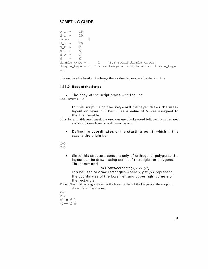
• Since this structure consists only of orthogonal polygons, the layout can be drawn using series of rectangles or polygons. The command
z=DrawRectangle(x,y,x1,y1) can be used to draw rectangles where x,y,x1,y1 represent the coordinates of the lower left and upper right corners of the rectangle.
For ex. The first rectangle drawn in the layout is that of the flange and the script to draw this is given below.
x=0 y=0 x1=x+f_l y1=y+f_w
31
SCRIPTING GUIDE
z=DrawRectangle(x,y,x1,y1)
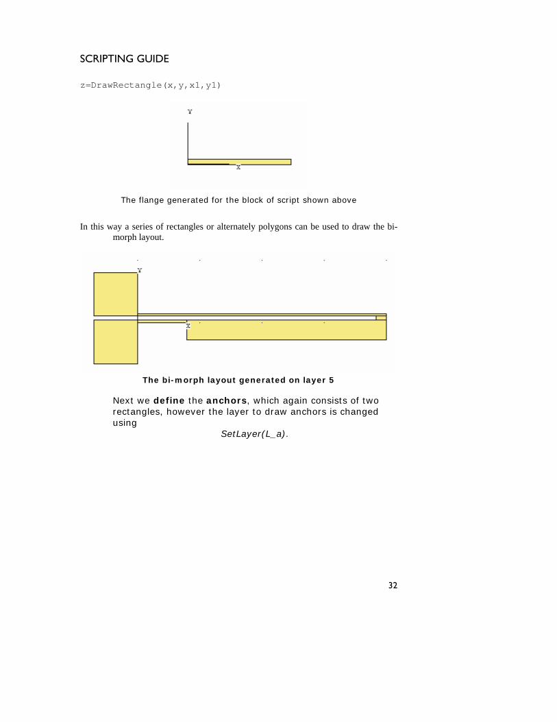
The flange generated for the block of script shown above
In this way a series of rectangles or alternately polygons can be used to draw the bi-
morph layout.
The bi-morph layout generated on layer 5
Next we define the anchors, which again consists of two rectangles, however the layer to draw anchors is changed using
SetLayer(L_a).
32
SCRIPTING GUIDE
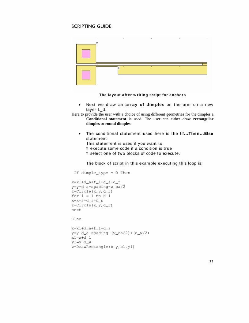
The layout after writing script for anchors
an array of dimples on the arm on a new
th a choice of using different geometries for the dimples a Conditional statement is used. The user can either draw rectangular
or round dimples.
al statement used here is the If...Then...Else
statement is used if you want to dition is true
of code to execute.
k of script in this example executing this loop is:
+f_l+d_s+d_r spacing-w_ca/2
=Circfor i x=x+2*z=Circnext
x=x1+dy=y-d_a-spacing-(w_ca/2)+(d_w/2) x1=x+d1=y-d_w z=D w
• Next we drawlayer L_d.
provide the user wiHere to
dimples
• The conditionstatement This
* execute some code if a conf two blocks * select one o
blocThe
imple_type = 0 Then If d
x=x1+d_a=y-d_a-yz le(x,y,d_r)
= 1 to N-1 d_r+d_s le(x,y,d_r)
Else
_a+f_l+d_s
_l y
ra Rectangle(x,y,x1,y1)
33
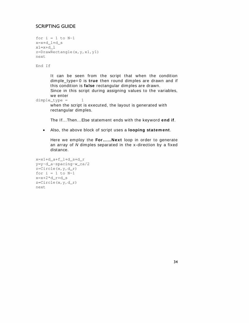
SCRIPTING GUIDE
for i = 1 to N-1 x=x+d_x1=x+dz=DrawRectangle(x,y,x1,y1) ext
n from the script that when the condition 0 is true then round dimples are drawn and if s false rectangular dimples are drawn.
during assigning values to the variables, we enter
diwhen the script is executed, the layout is generated with
hen...Else statement ends with the keyword end if.
of script uses a looping statement.
fixed
=x1+d_a+f_l+d_s+d_r y=y-d_a-spacing-w_ca/2 z=Circle(x,y,d_r) for i = 1 to N-1 x=x+2*d_r+d_s z=Circle(x,y,d_r) next
l+d_s _l
n End If
eeIt can be spe=dimple_ty
this condition iSince in this script
mple_type = 1
rectangular dimples.
The If...T
• Also, the above block
Here we employ the For……Next loop in order to generatean array of N dimples separated in the x-direction by adistance.
x
34
SCRIPTING GUIDE
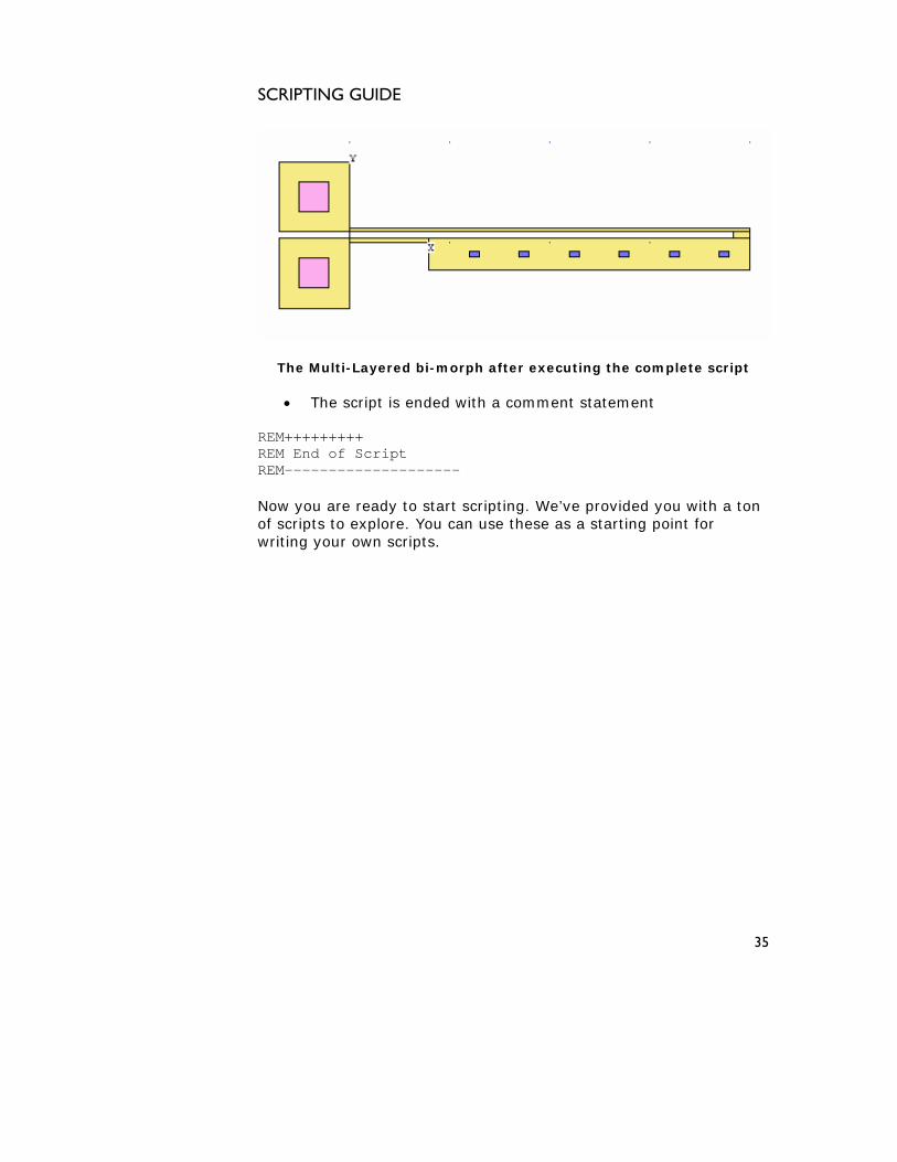
The Multi-Layered bi-morph after executing the complete script
• The script is ended with a comment statement
REM+++++++++ REM End of Script REM-------------------- Now you are ready to start scripting. We’ve provided you with a ton of scripts to explore. You can use these as a starting point for writing your own scripts.
35

SCRIPTING GUIDE
36
SCRIPTING GUIDE
Parametric element library MEMS Parametric Elements
37

SCRIPTING GUIDE
38
SCRIPTING GUIDE
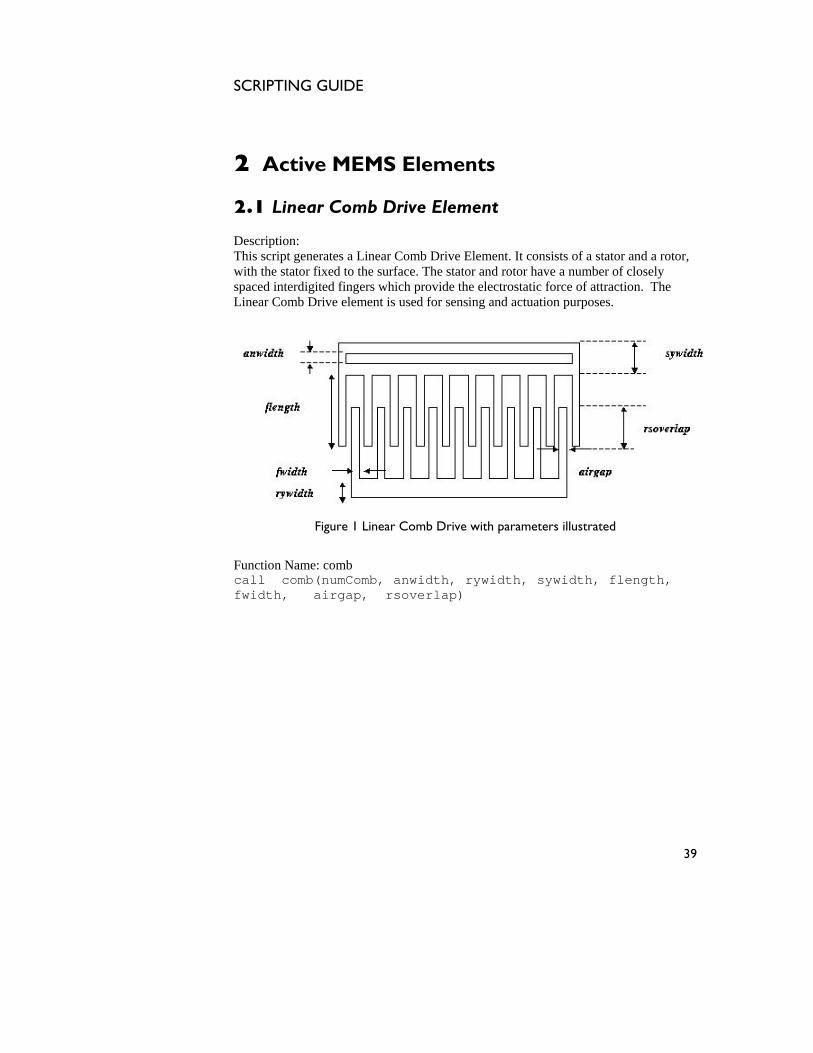
EMS Elements
b Drive Element Descript :This scr g ates a Linear Co sists of a stator and a rotowith the stator fixed to the surface. The stator and rotor have a number of closely spaced interdigited fingers which tic force of attraction. The
inear Comb Drive element is used for sensing and actuation purposes.
2 Active M
2.1 Linear Com
ion ipt ener mb Drive Element. It con r,
provide the electrostaL
Figure 1 Linear Comb Drive with parameters illustrated
unction Name: comb
h, Fcall comb(numComb, anwidth, rywidth, sywidth, flengtfwidth, airgap, rsoverlap)
39
SCRIPTING GUIDE
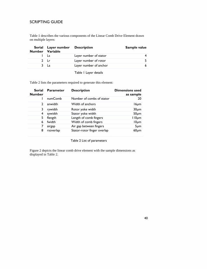
able 1 describes the various components of the LiT near Comb Drive Element drawn
ers:
er of stator 4
on multiple lay
Serial Number
Layer number Variable
Description Sample value
1 Ls Layer numb
2 Lr Layer number of rotor 5 3 La Layer number of anchor 6
Table 1 Layer details
Table 2 lists the parameters required to generate this element:
Serial Number
Parameter Description Dimensions used as sample
1 numComb Number of combs of stator 20
2 anwidth Width of anchors 16µm
3 rywidth Rotor yoke width 30µm 4 sywidth Stator yoke width 50µm 5 flength Length of comb fingers 110µm 6 fwidth Width of comb fingers 10µm 7 airgap Air gap between fingers 5µm 8 rsoverlap Stator-rotor finger overlap 60µm
Table 2 List of parameters
Figure 2 depicts t ns as
isplayed in Table 2. he linear comb drive element with the sample dimensio
d
40
SCRIPTING GUIDE
Figure 2 Linear Comb Drive
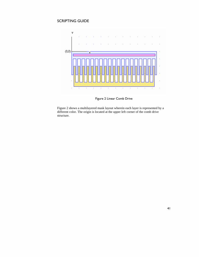
Figure 2 o ltilayer each layer is represe a different col rigin is corner of the combstructure
sh ws a mu ed mask layout wherein nted byor. The o located at the upper left drive
.
41
SCRIPTING GUIDE
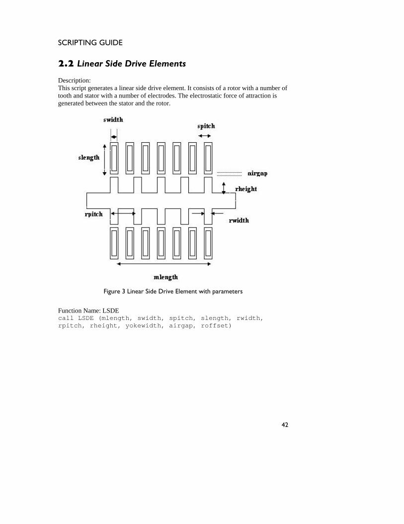
2.2 Linear Side
This script generates a linear side drive element. It consists of a rotor with a number of tooth and stator with a number of electrodes. The electrostatic force of attraction is generated between the stator and the rotor.
Drive Elements Description:
Figure 3 Linear Side Drive Element with parameters
Function Name: LSDE call LSDE (mlength, swidth, spitch, slength, rwidth, rpitch, rheight, yokewidth, airgap, roffset)
42
SCRIPTING GUIDE
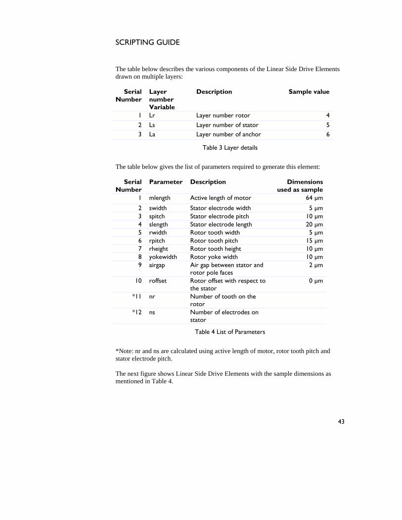
The table below describes the various components of the Linear Side Drive Ele
rawn on multiple layers: ments
d
Serial Number
Layer number Variable
Description Sample value
1 Lr Layer number rotor 4
2 Ls Layer number of stator 5 3 La Layer number of anchor 6
Table 3 Layer details
The table below gives the list of parameters required to generate this element:
Serial Number
Parameter Description Dimensions used as sample
1 mlength Active length of motor 64 µm
2 swidth Stator electrode width 5 µm 3 spitch Stator electrode pitch 10 µm 4 slength Stator electrode length 20 µm 5 rwidth Rotor tooth width 5 µm 6 rpitch Rotor tooth pitch 15 µm 7 rheight Rotor tooth height 10 µm 8 yokewidth Rotor yoke width 10 µm 9 airgap Air gap between stator and
rotor pole faces 2 µm
10 roffset Rotor offset with respect to the stator
0 µm
*11 nr Number of tooth on the rotor
*12 ns Number of electrodes on stator
Table 4 List of Parameters
Note: nr and ns are calculated using active length of motor, rotor tooth pitch and
*stator electrode pitch. The next figure shows Linear Side Drive Elements with the sample dimensions as mentioned in Table 4.
43
SCRIPTING GUIDE
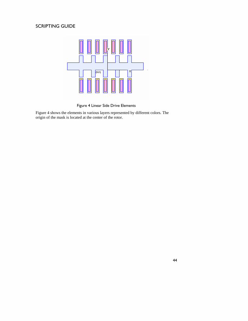
Figure 4 Linear Side Drive Elements
ows the elements in various layers represented by different coloorigin o e cated tor. Figure 4 sh rs. The
f th mask is lo at the center of the ro
44
SCRIPTING GUIDE
2.3
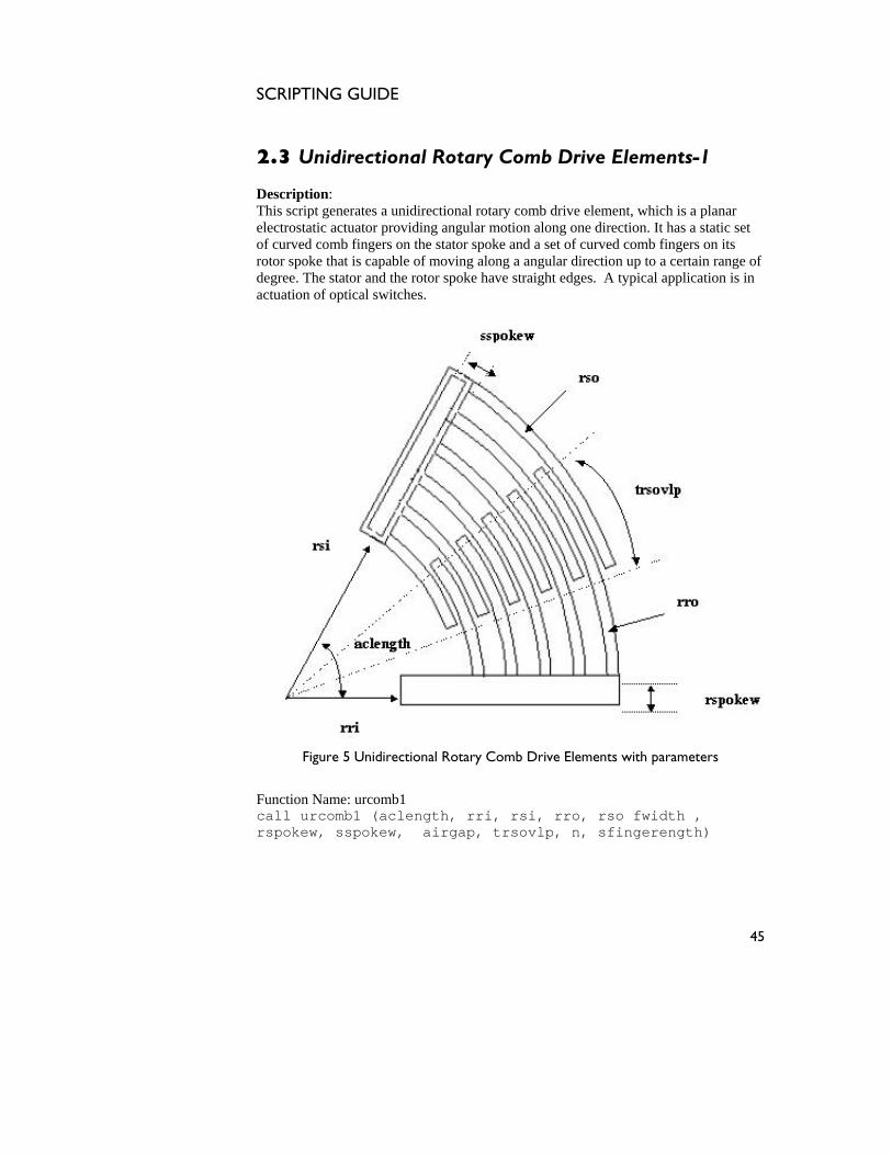
Unidirectional Rotary Comb Drive Elements-1
Description: s script generates a unidirectional rotary comb drive element, which is a planar
ge of application is in
actuation of optical switches.
Thielectrostatic actuator providing angular motion along one direction. It has a static set of curved comb fingers on the stator spoke and a set of curved comb fingers on its rotor spoke that is capable of moving along a angular direction up to a certain randegree. The stator and the rotor spoke have straight edges. A typical
Figure 5 Unidirectional Rotary Comb Drive Elements with parameters
Function Name: urcomb1 call urcomb1 (aclength, rri, rsi, rro, rso fwidth , rspokew, sspokew, airgap, trsovlp, n, sfingerength)
45
SCRIPTING GUIDE
The table below describes the various components of the Unidirect
rive Elements drawn on multiple layers: ional Rotary Comb
D
Serial Number
Layer number Variable
Description Sample value
1 Layer_comb Layer number of comb 4
2 Layer_anchor Layer number of anchor 5
Table 5 Layer details
The table below gives the list of parameters required to generate this element:
Serial Number
Parameter Description Dimensions used as sample
1 aclength Active angular comb length,
60 degrees
2 rri Inner radius of rotor 100 µm
3 rsi Inner radius of stator comb 20 µm *4 rro Outer radius of rotor
comb
*5 rso Outer radius of stator comb
6 fwidth Width of comb fingers 10 µm 7 rspokew Rotor spoke width 25 µm 8 sspokew Stator spoke width 25 µm 9 airgap Airgap between adjacent
comb fingers 5 µm
10 trsovlp Angular stator-rotor finger overlap
20 degrees
11 n Number of fingers on stator
6
Table 6 List of Parameters
*Note: 1.rso is calculated using rsi, n, fwidth, airgap. 2.rro is calculated using rso, fwidth, airgap. The next figure depicts a Unidirectional Rotary Comb Drive Element with 6 fingers on its stator, as viewed in Intellimask with the dimensions mentioned in Table 6.
46
SCRIPTING GUIDE
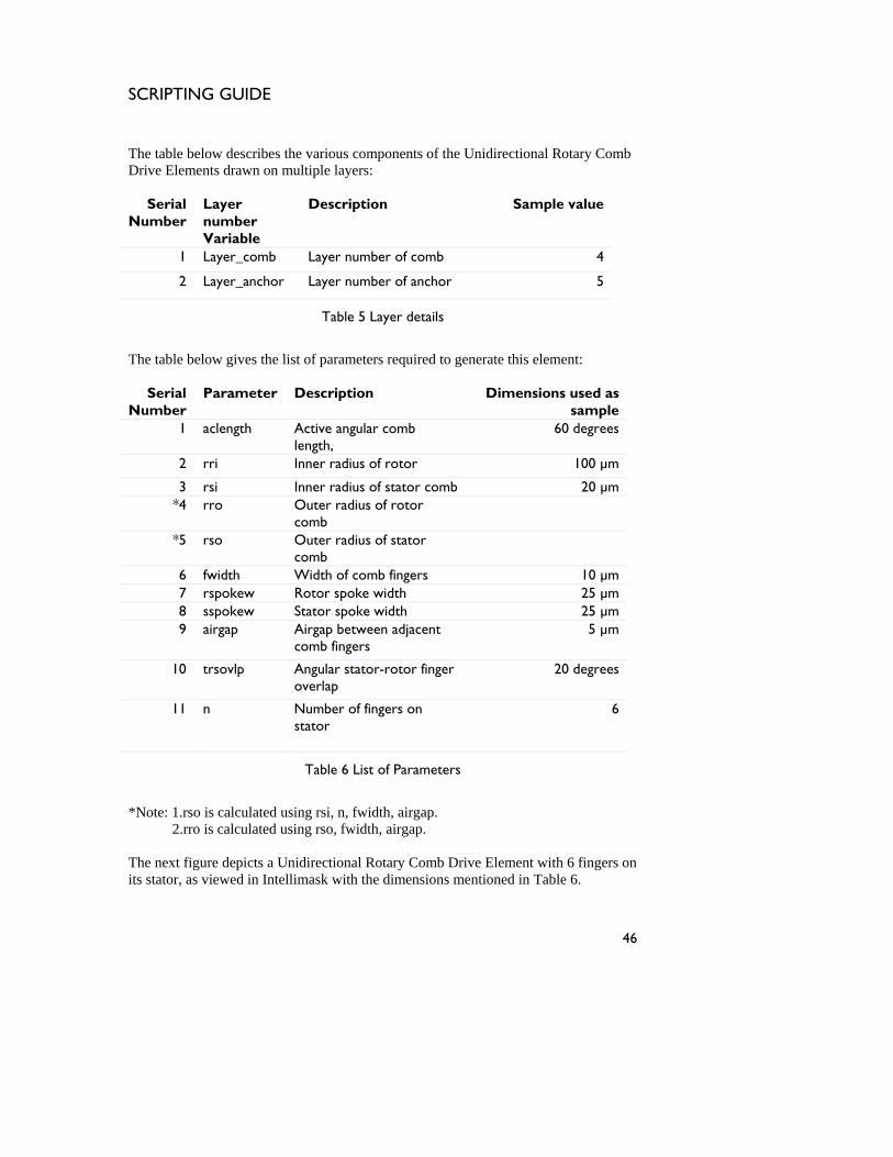
Figure 6 Un ive Elements
The fig s e two-la h layer is represent different col mb is located at the center of circular nd th with the x-axis.
idirectional Rotary Comb Dr
ure hows thor. The c
yered mask layout wherein eac ed bythe
ao
b fingers a generated with its origin
com e rotor spoke aligned
47
SCRIPTING GUIDE
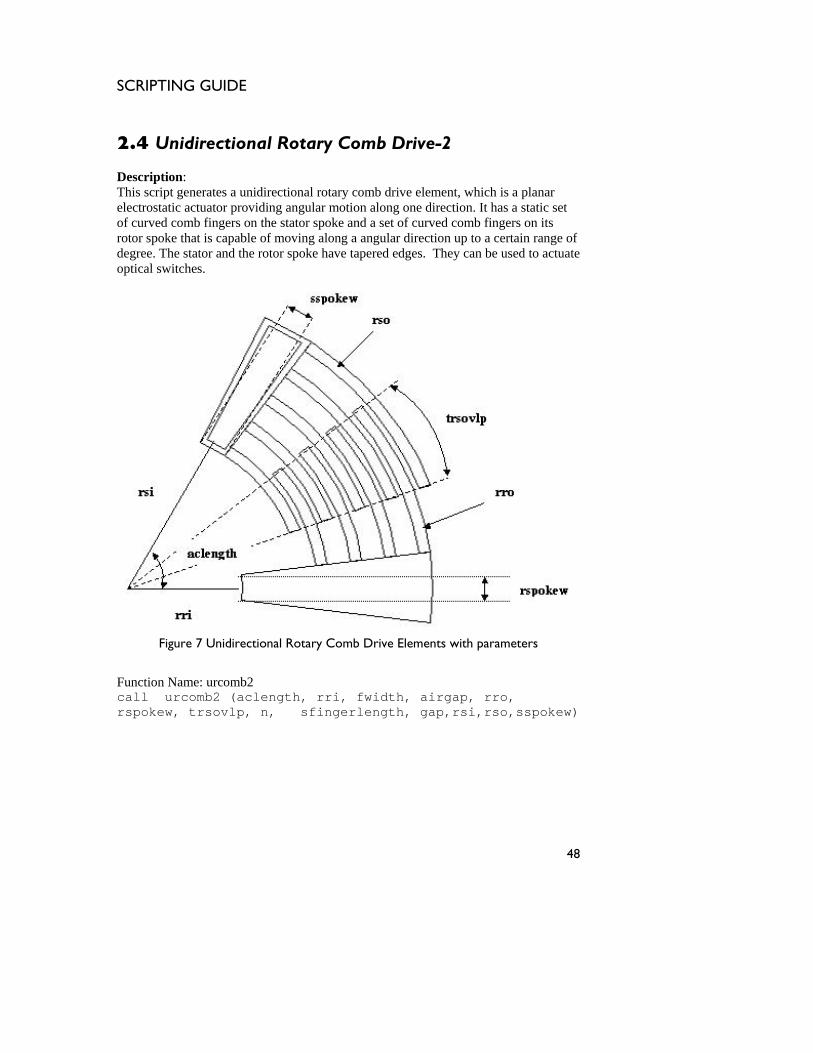
2.4 Unidirectional Rotary Comb Drive-2 Description: This script generates a unidirectional rotary mb drive element, which is a planar electrostatic actu s a static set
f curved comb fingers on the stator spoke and a set of curved comb fingers on its
coator providing angular motion along one direction. It ha
orotor spoke that is capable of moving along a angular direction up to a certain range ofdegree. The stator and the rotor spoke have tapered edges. They can be used to actuateoptical switches.
Figure 7 Unidirectional Rotary Comb Drive Elements with parameters
Function Name: urcomb2 call urcomb2 (aclength, rri, fwidth, airgap, rro, rspokew, trsovlp, n, sfingerlength, gap,rsi,rso,sspokew)
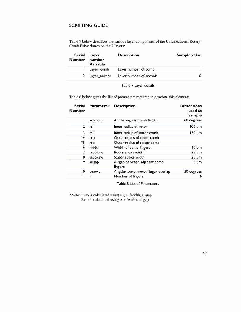
48
SCRIPTING GUIDE
able 7 below describes the various layer components of the UnidirectionaT l Rotary
awn on the 2 layers: Comb Drive dr
Serial Number
Layer number Variable
Description Sample value
1 Layer_comb Layer number of comb 1
2 Layer_anchor Layer number of anchor 6
Table 7 Layer details
Table 8 below gives the list of parameters required to generate this element:
Serial Number
Parameter Description Dimensions used as sample
1 aclength Active angular comb length 60 degrees
2 rri Inner radius of rotor 100 µm
3 rsi Inner radius of stator comb 150 µm *4 rro Outer radius of rotor comb *5 rso Outer radius of stator comb 6 fwidth Width of comb fingers 10 µm 7 rspokew Rotor spoke width 25 µm 8 sspokew Stator spoke width 25 µm 9 airgap Airgap between adjacent comb
fingers 5 µm
10 trsovlp Angular stator-rotor finger overlap 30 degrees 11 n Number of fingers 6
Table 8 List of Parameters
*Note: 1.rso is calculated using rsi, n, fwidth, airgap. 2.rro is calculated using rso, fwidth, airgap.
49
SCRIPTING GUIDE
The next figure depicts the Unidirectional Rotary Comb Drive Elements as viewed in Intellimask with the sample dimensions mentioned in Table 8.
Figure 8 Un ve Elements
The figu s o-la herein each layer is represen different col b is at the center of thcircular c m rs and th xis.
idirectional Rotary Comb Dri
re hows the tw yered mask layout w ted by aor. The comb finge
generated with its origin locatede rotor spoke aligned with the x-a
e o
50
SCRIPTING GUIDE
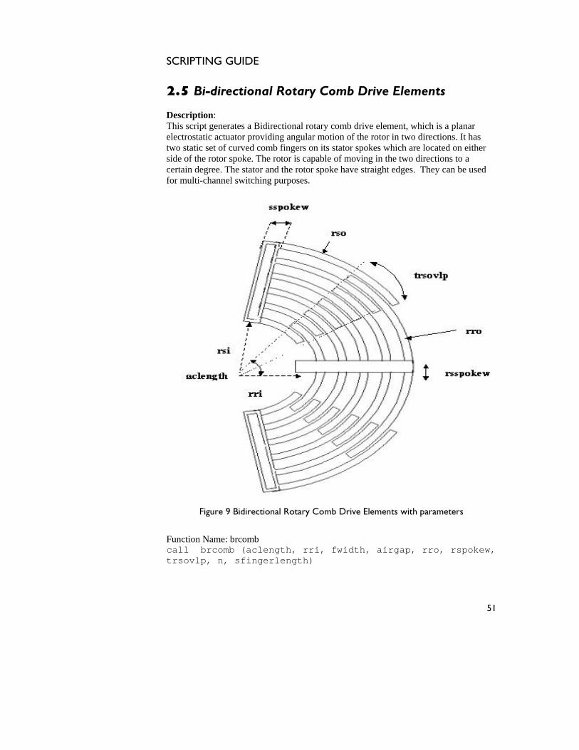
2.5 Bi-directional Rotary Comb Drive Elements Description:
his
script generates a Bidirectional rotary comb drive element, which is a planar lectrostatic . It has
o static se on either de of the rotor spoke. The rotor is capable of moving in the two directions to a
certain degree. T can be used r multi-channel switching purposes.
Te actuator providing angular motion of the rotor in two directions
t of curved comb fingers on its stator spokes which are located twsi
he stator and the rotor spoke have straight edges. Theyfo
Figure 9 Bidirectional Rotary Comb Drive Elements with parameters
Function Name: brcomb call brcomb (aclength, rri, fwidth, airgap, rro, rspokew, trsovlp, n, sfingerlength)
51
SCRIPTING GUIDE
The table below describes the various components of th
rive Elements drawn on multiple layers: e Bidirectional Rotary Comb
D
Serial Number
Layer number Variable
Description Sample value
1 Ls Layer number of stator 1
2 Lr Layer number of rotor 2
3 La Layer number of anchor
3
Table 9 Layer details
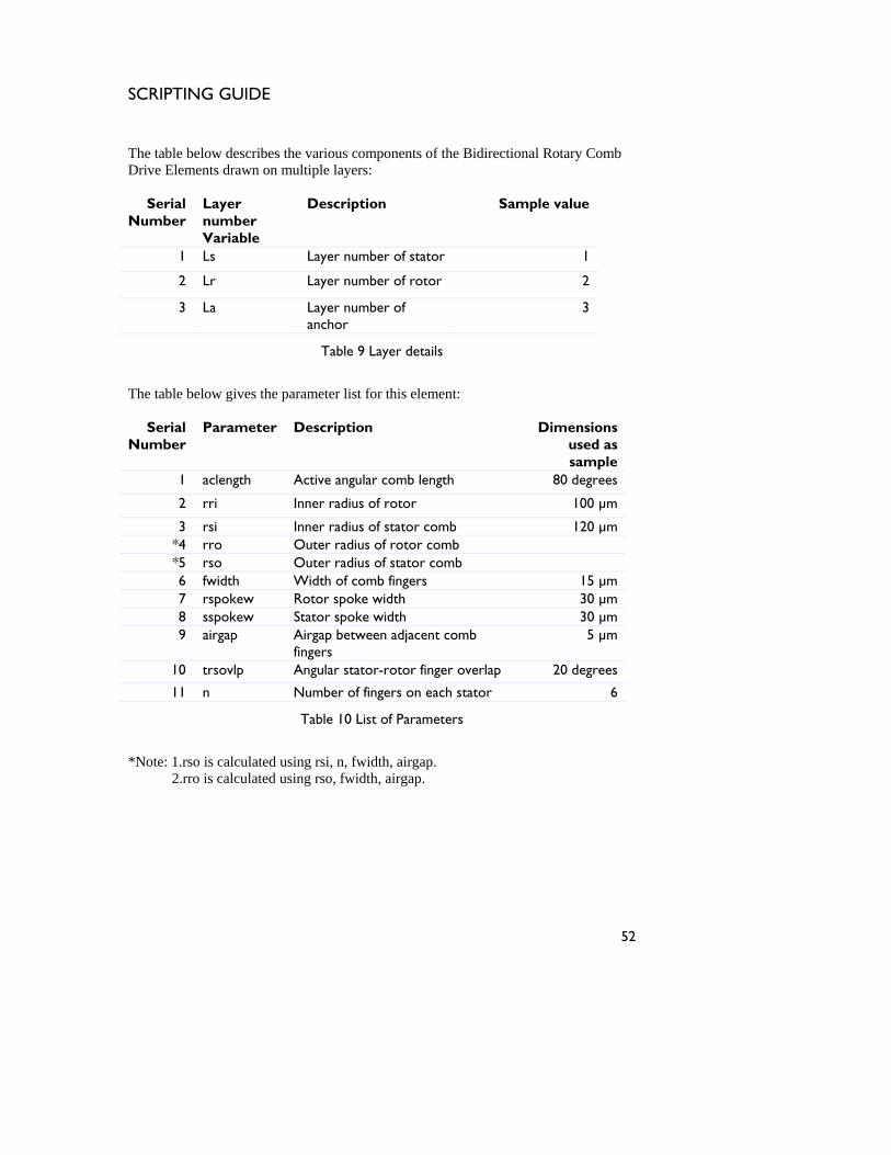
The table below gives the parameter list for this element:
used as sample
1 aclength Active angular comb length 80 degrees
Serial
Number Parameter Description Dimensions
2 rri Inner radius of rotor 100 µm
3 rsi Inner radius of stator comb 120 µm *4 rro Outer radius of rotor comb *5 rso Outer radius of stator comb 6 fwidth Width of comb fingers 15 µm 7 rspokew Rotor spoke width 30 µm 8 sspokew Stator spoke width 30 µm 9 airgap Airgap between adjacent comb
fingers 5 µm
10 trsovlp Angular stator-rotor finger overlap 20 degrees
11 n Number of fingers on each stator 6
Table 10 List of Parameters
*Note: 1.rso is calculated using rsi, n, fwidth, airgap. 2.rro is calculated using rso, fwidth, airgap.
52

SCRIPTING GUIDE
The next figure depicts a Bidirectional Rotary Comb Drive Element with 6 fingers oneach of its stator, as generated in Int
ellimask with the dimensions mentioned in Table
0.
jects cannot be created from editing field codes.
Figure 10 Bidi omb Drive Elements
The figure shows the multilayered mask layout wherein each layer is represented by a different color. The comb is gen center of the
rcular comb fingers and the rotor spoke aligned with the x-axis.
1
Error! Ob
rectional Rotary C
erated with its origin located at theci
53
SCRIPTING GUIDE
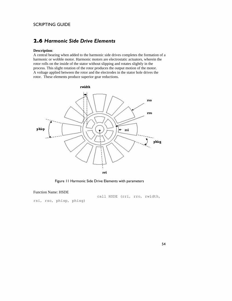
2.6 Harmonic Side Drive Elements DescriptionA central be ation of a harmonic or wobble m uators, wherein the
tor rolls on the inside of the stator without slipping and rotates slightly in the
: aring when added to the harmonic side drives completes the form
otor. Harmonic motors are electrostatic actroprocess. This slight rotation of the rotor produces the output motion of the motor. A voltage applied between the rotor and the electrodes in the stator hole drives the rotor. These elements produce superior gear reductions.
Figure 11 Harmonic Side Drive Elements with parameters
Function Name: HSDE call HSDE (rri, rro, rwidth, rsi, rso, phisp, phisg)
54
SCRIPTING GUIDE
The table below describes the various components
lement drawn on multiple layers: of the Harmonic Side Drive
E
Serial Number
Layer number Variable
Description Sample value
1 Ls Layer number of stator
1
2 Lr Layer number of rotor 2
Table 11 Layer details
The table below gives the list of parameters required to generate this element:
Serial Number
Parameter Description Dimensions used as sample
1 rri Inner rotor radius 20 µm
2 rro Outer rotor radius 80 µm
3 rwidth Rotor ring width 15 µm 4 rsi Stator inner radius 90 µm 5 rso Stator outer radius 180 µm 6 phisp Stator pole angle 20 degrees
*7 phisg Angular gap between stator poles degrees
8 nr Number of electrodes on rotor
6
9 ns Number of electrodes on stator
12
Table 12 List of Parameters
Note: 1. Phisg is calculated from phisp. *
55

SCRIPTING GUIDE
The figure below depicts the Harmonic Side Drive Element as viewed in IntelliMask with the sample dimensions mentioned in Table 12.
bjects ca d from editing f
Side Drive Elements
The figure shows a two-layered ayout wherein each layer is represented by a different col he origin is lo stator.
Error! O nnot be create ield codes.
Figure 12 Harmonic
mask lor. T cated at the center of the
56
SCRIPTING GUIDE
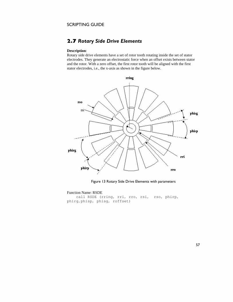
2.7 Rotary Side Drive Elements
escription: DRotary side stator lectrodes. T n stator nd the rotor. With a zero offset, the first rotor tooth will be aligned with the first
stator electrodes, i.e., th
drive elements have a set of rotor tooth rotating inside the set ofhey generate an electrostatic force when an offset exists betweee
ae x-axis as shown in the figure below.
Figure 13 Rotary Side Drive Elements with parameters
Function Name: RSDE call RSDE (rring, rri, rro, rsi, rso, phirp, phirg,phisp, phisg, roffset)
57
SCRIPTING GUIDE
he table below describes the vaT rious components of the Rotary Side Drive Elements
ple layers:
1 Ls Layer number of stator
0
drawn on multi
Serial Number
Layer number Variable
Description Sample value
2 Lr 1 Layer number of rotor
Table 13 Layer details
Serial Number
Parameter Description Dimensions used as sample
1 rring Inner radius of rotor ring 20 µm
The parameters required to generate this element are tabulated below:
2 rri Inner rotor radius 35 µm
3 rro Outer rotor radius 85 µm
4 rsi Stator inner radius 90 µm 5 rso Stator outer radius 180 µm 6 phirp Angular width of rotor pole
(tooth) 20 degrees
7 phirg Angular gap between adjacent rotor teeth
25 degrees
8 phisp Angular width of stator pole 20 degrees 9 phisg Angular gap between adjacent
stator poles 10 degrees
10 roffset Angular offset of rotor with respect to stator
5 degrees
*11 nr Number of tooth on rotor *12 ns Number of electrodes on stator
Table 14 List of Parameters
*Note: nr is calculated using phirp and phirg, while ns is calculated using phisp and phisg.
58

SCRIPTING GUIDE
The next figure depicts a Rotary Side Drive Element having 8 teeth in its rotor and 12 lectrodes in its stator, as viewed in IntelliMask with the sample dimensions
me 4.
jects cannot be created from editing field codes.
Figure 1 ments
a
entioned i
n Table 1
Error! Ob
4 Rotary Side Drive Ele
The figure shows a two layered mask layout wherein each layer is represented by
ifferent color. The origin is located at the center of the rotor ring. d
59
SCRIPTING GUIDE
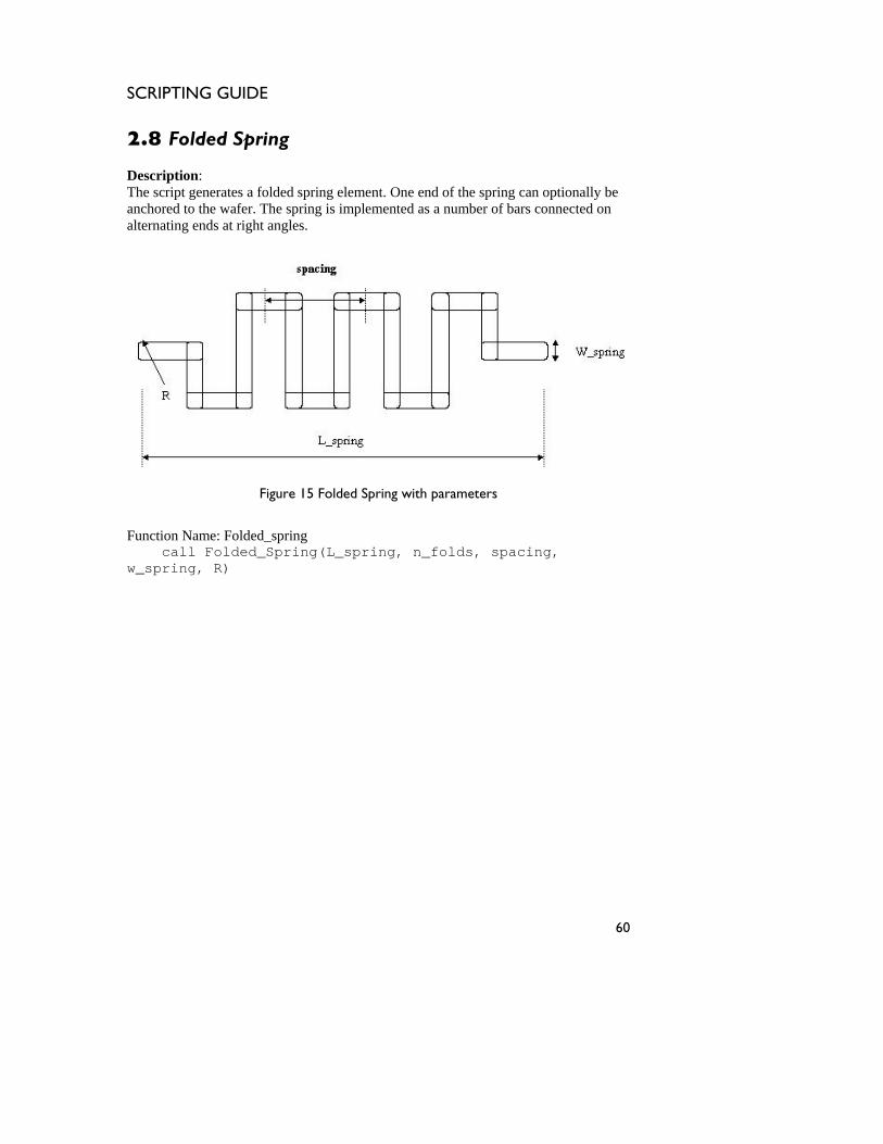
2.8 Folded Spring Description: The script generates a folded spring element. One end of the spring can optionally be anchored to the wafer. The spring is implemented as a number of bars connected on alternating ends at right angles.
Figure 15 Folded Spring with parameters
Function Name: Folded_spring call Folded_Spring(L_spring, n_folds, spacing, w_spring, R)
60
SCRIPTING GUIDE
The table below gives the layer number variable of the folded spring drawn:
umber number Sample value
ng 6
Serial Layer Description
NVariable
1 Layer_spring Layer number to draw spri
Table 15 Layer details
The table below gives the list of parameters required to generate this element:
Serial Parameter Description Number
Dimensions used as sample
*1 L_spring Overall length of the spring 320 µm
2 n_folds Number of folds of the spring 6 µm
3 spacing Inter tether spacing 80 µm 4 w_spring Width of the spring 15 µm 5 R Curvature of the spring
corners 3 µm
Table 16 List of Parameters
*Note: L_spring is calculated using number of folds of the spring, width of spring and the spacing. The next figure shows the folded spring element generated in IntelliMask with the dimensions as shown in Table 16.
Error! Objects cannot be created from editing field codes.
ering the origin at the lower left corner as the starting point.
Figure 16 Folded Spring
The mask is drawn consid
61

SCRIPTING GUIDE
62
SCRIPTING GUIDE
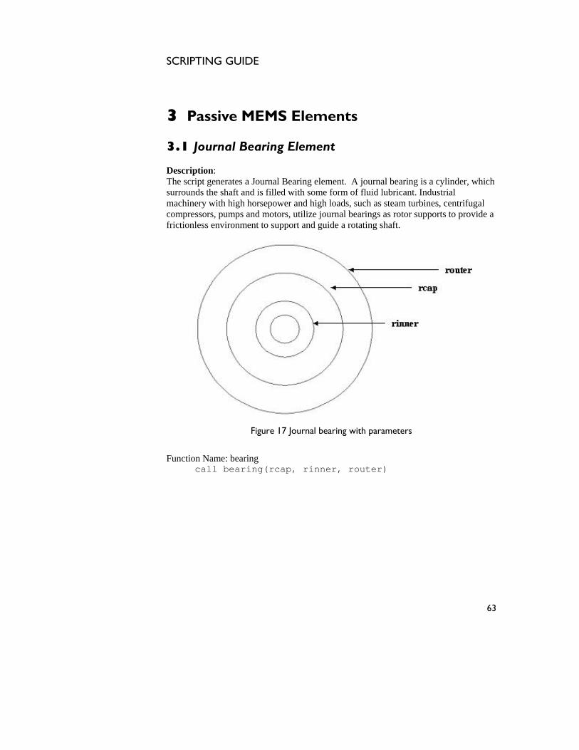
3 Passive MEMS Elements
.1 Journal Bearing Element
escription:
fugal compressors, pumps and motors, utilize journal bearings as rotor supports to provide a frictionless environment to support and guide a rotating shaft.
3
DThe script generates a Journal Bearing element. A journal bearing is a cylinder, whichsurrounds the shaft and is filled with some form of fluid lubricant. Industrial machinery with high horsepower and high loads, such as steam turbines, centri
Figure 17 Journal bearing with parameters
Function Name: bearing call bearing(rcap, rinner, router)
63
SCRIPTING GUIDE
he table below describes the various components of the Journal BeariT ng drawn on
:
1
multiple layers
Serial Number
Layer number Variable
Description Sample value
1 La1 Layer number of rcap
2 La2 Layer number of rinner 2 3 3 La3 Layer number of router
*4 La4 Layer number of rinner1 4
Table 17 Layer details
*Note: La4 is the innermost layer whose radius is dependent on the other parameters. The table below gives the list of parameters required to generate this element:
Serial Number
Parameter Description Dimensions used as sample
1 rcap Radius of cap on central shaft 200 µm
2 rinner Inner radius of journal rotor 100 µm
3 router Outer radius of journal rotor 300 µm
4 rinner1 Inner most radius
Table 18 List of Parameters
64

SCRIPTING GUIDE
The next figure shows the Journal Bearing element with the sample dimensions as mentioned in Table 18, generated in IntelliMask.
bjects ted from editing field
ng
The journal bearing element layer represented by a different color is shown in the figure ve. The orig r of the shaft and cap.
Error! O cannot be crea codes.
Figure 18 Journal Beari
with each abo in for the mask is the cente
65
SCRIPTING GUIDE
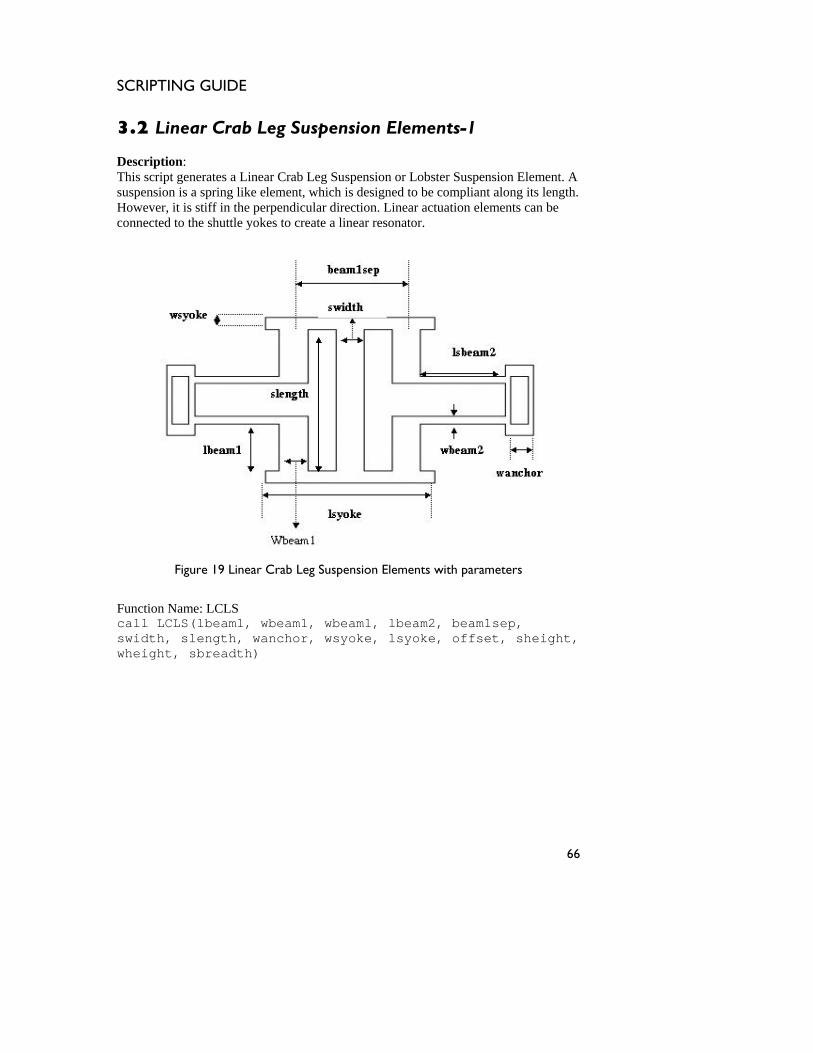
3.2 Linear Crab Leg Suspension Elements-1
escription:
his script generates a Linear Crab Leg Suspension or Lobster Suspension Element. A suspension is a spring like element, which is designed to be compliant along its length. However, it is stiff in the perpendicular direction. Linear actuation elements can be connected to the shuttle yokes to create a linear resonator.
DT
Figure 19 Linear Crab Leg Suspension Elements with parameters
Function Name: LCLS call LCLS(lbeam1, wbeam1, wbeam1, lbeam2, beam1sep, swidth, slength, wanchor, wsyoke, lsyoke, offset, sheight, wheight, sbreadth)
66
SCRIPTING GUIDE
he table below describes the various components of the Linear CrabT Leg Suspension
on multiple layers:
n Element
4
Elements drawn
Serial Number
Layer number
Description Sample value
Variable 1 Ls Layer number of Linear
Crab Leg Suspensio
2 3 La Layer number of anchor
Table 19 Layer details
Number Dimensions
used as sample 1 lbeam1 Length of beam 1 40 µm
The table below gives the design parameters required to generate this element:
Serial Parameter Description
2 wbeam1 Width of beam 1 20 µm
3 lbeam2 Length of beam 2 60 µm 4 wbeam2 Width of beam 2 6 µm 5 beam1sep Separation between type 1
beams 80 µm
6 swidth Width of shuttle width 20 µm 7 slength Length of shuttle 120 µm 8 wanchor Width of anchor support 20 µm 9 wsyoke Width of shuttle yoke 10 µm
10 lsyoke Length of shuttle yoke 120 µm
Table 20 List of Parameters
67
SCRIPTING GUIDE
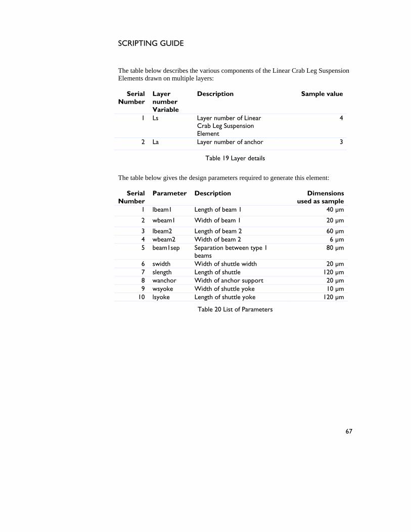
The next figure depicts the Linear Crab Leg Suspension Elements as viewed in IntelliMask with the sample dimensions shown in Table 20.
Figure 2 uspension Elements
Figure 2 h yer ch layer is repre a different color. The origin is t the upper left corner of the element.
0 Linear Crab Leg S
0 s ows a two la ed mask layout wherein ea located a
sented by
68
SCRIPTING GUIDE
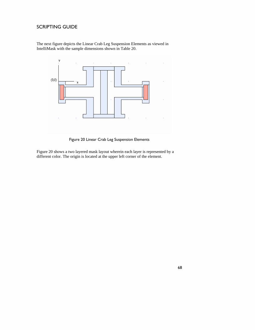
3.3 Linear Crab Leg Suspension Elements-2
escription:
his script g is a spring like element it is stiff along its the perpen
ctuators or other mechanical elements like comb-drives can be connected to the
DT enerates a Linear Crab Leg Suspension Element. A suspension
, which is designed to be compliant along its length. However, dicular direction.
Ayokes at the ends of the shuttle mass.
Figure 21 Linear Crab Leg Suspension Elements with parameters
Function Name: LCLSb call LCLSb (lbeam1, wbeam1, wbeam2, lbeam2, beam1sep, swidth, slength, wanchor, wsyoke, lsyoke, aprojection, sprojection, sheight, sheight1)
69
SCRIPTING GUIDE
The table below gives the layer details of the Linear Crab Leg Suspension Elements:
ayer Description Sample value
Serial LNumber number
Variable 1 Ls Layer number of crab 1
Table 21 Layer details
The table below gives the list of parameters required to generate this element:
Serial Number
Parameter Description Dimensions used as sample
1 lbeam1 Length of beam 1
60 µm
2 wbeam1 Width of beam 1
6 µm
3 lbeam2 Length of beam 2
40 µm
4 wbeam2 Width of beam 2 20 µm
5 beam1sep Separation between type 30 µm 1 beams
6 swidth Width of shuttle width
40 µm
7 slength Length of shuttle
70 µm
8 wanchor Width of anchor support
30 µm
9 wsyoke Width of shuttle yoke
10 µm
10 lsyoke Length of shuttle yoke
80 µm
Table 22 List of Parameters
70

SCRIPTING GUIDE
The next figure depicts the Linear Crab Leg Suspension Elements generated in IntelliMask with the sample dimensions shown in Table 22.
bjects ca d from editing fiel
e 22 Linear Crab Leg Suspension Elements
The figu s the mask lay spension element. The element dering t in, which is located at upper left corner.
Error! O nnot be create d codes.
Figur
re show is d
out of the linear crab leg suhe starting point as the origrawn consi the
71
SCRIPTING GUIDE
3.4 Linear Folded Beam Suspension Elements DescriptionThis script g eam suspension is a sp ng its length.
owever, it is stiff in the perpendicular direction. Actuators or other mechanical
: enerates a Linear Folded Beam Suspension Element. A folded b
ring like element, which is designed to be compliant aloHelements like comb-drives can be connected to the yokes at the ends of the shuttle mass.
Figure 23 Linear Folded Beam Suspension Elements with parameters
Function Name: LFBS call LFBS(lbeam, wbeam, beamsep, wbar, swidth ,wanchor, wsyoke, lsyoke)
72
SCRIPTING GUIDE
The table below describes the various components of the Linear Folded Beam Suspension Elements drawn on multiple layers:
Serial Number
Layer number Variable
Description Sample value
1 Ls Layer number of structure 6
2 La Layer number of anchor 5
Table 23 Layer details
The table below gives the list of parameters required to generate this element:
Serial Number
Parameter Description Dimensions used as sample
1 lbeam Length of beam 70 µm
2 wbeam Width of beam 5 µm
3 beamsep Separation between beams 20 µm
4 wbar Width of connecting bar 10 µm 5 swidth Width of shuttle width 30 µm 6 wanchor Width of anchor support 15 µm 7 wsyoke Width of shuttle yoke 10 µm 8 lsyoke Length of shuttle yoke 70 µm
Table 24 List of Parameters
73

SCRIPTING GUIDE
The next figure depicts the Linear Folded Beam Suspension Elements generated in Intellimask with the dimensions shown in Table 24.
Error! Objects cannot be created from editing field codes.
Figure 24 Linear Folded Beam Suspension Elements
The figure shows the two layered mask layout wherein each layer is represented by a different color. The origin is located at the upper left corner of the element.
74

SCRIPTING GUIDE
75

SCRIPTING GUIDE
76
SCRIPTING GUIDE
4 MEMS Pack
ption: The pins hang vertically from the two long edges of the rectangular package, spaced at certain intervals. The pins fit through holes in the circuit board to which they are soldered or into a socket. The most common type of package for small and medium scale integrated circuits, have up to about 48 pins.
aging Elements 4.1 Dual Inline Pin Package Descri
Figure 25 Dual Inline Pin Package with parameters, also showning pin detail
Function Name: DIPP call DIPP(n,pitch,length,width,R,b,W,L1,L2,L3,overlap)
77
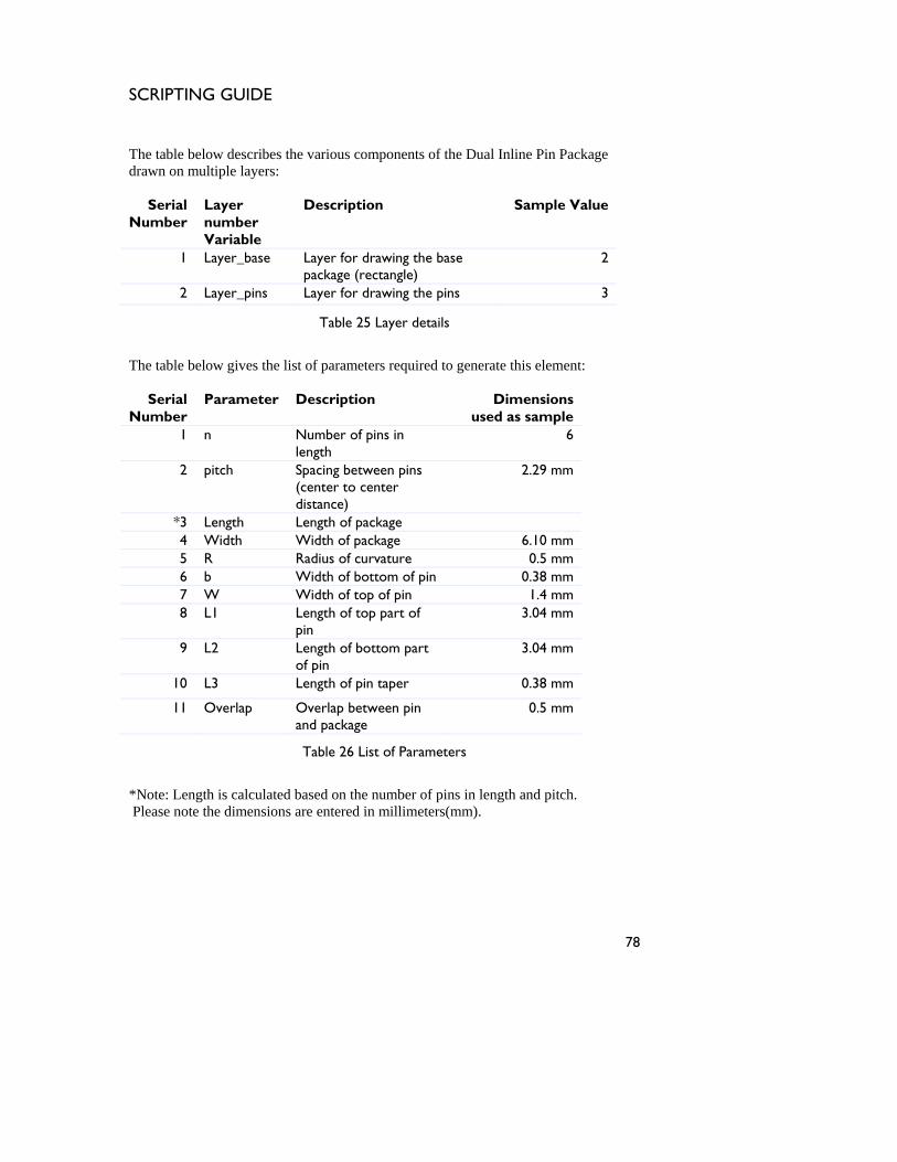
SCRIPTING GUIDE
he table below describes the various componeT nts of the Dual Inline Pin Package
ple layers:
1 Layer_base Layer for drawing the base package (rectangle)
2
drawn on multi
Serial Layer Description Sample Value Number number
Variable
2 Layer_pins Layer for drawing the pins 3
Table 25 Layer details
The table below gives the list of parameters required to generate this element:
Serial Number
Parameter Description Dimensions used as sample
1 n Number of pins in length
6
2 pitch Spacing between pins (center to center distance)
2.29 mm
*3 Leng th Length of package 4 Widt mm h Width of package 6.105 R Radius of curvature 0.5 mm 6 b Width of bottom of pin 0.38 mm 7 W Width of top of pin 1.4 mm 8 L1 Length of top part of
pin 3.04 mm
9 L2 Length of bottom part of pin
3.04 mm
10 L3 Length of pin taper 0.38 mm
11 Overlap Overlap between pin and package
0.5 mm
Table 26 List of Parameters
*Note: Length is calculated based on the number of pins in length and pitch. Please note the dimensions are entered in millimeters(mm).
78

SCRIPTING GUIDE
Figure 26 shows the Dual Inline Pin Package generated in IntelliMask with the sampdimensions shown in Table
le 26.
bjects ted from editing field code
Figure 26 Dual Inline Pin Package
The figure shows the two-lay rein each layer is represented by a different l in of wer left corner of the base layer.
Error! O cannot be crea s.
ered mask layout whe co or. The orig the mask is located at the lo
79
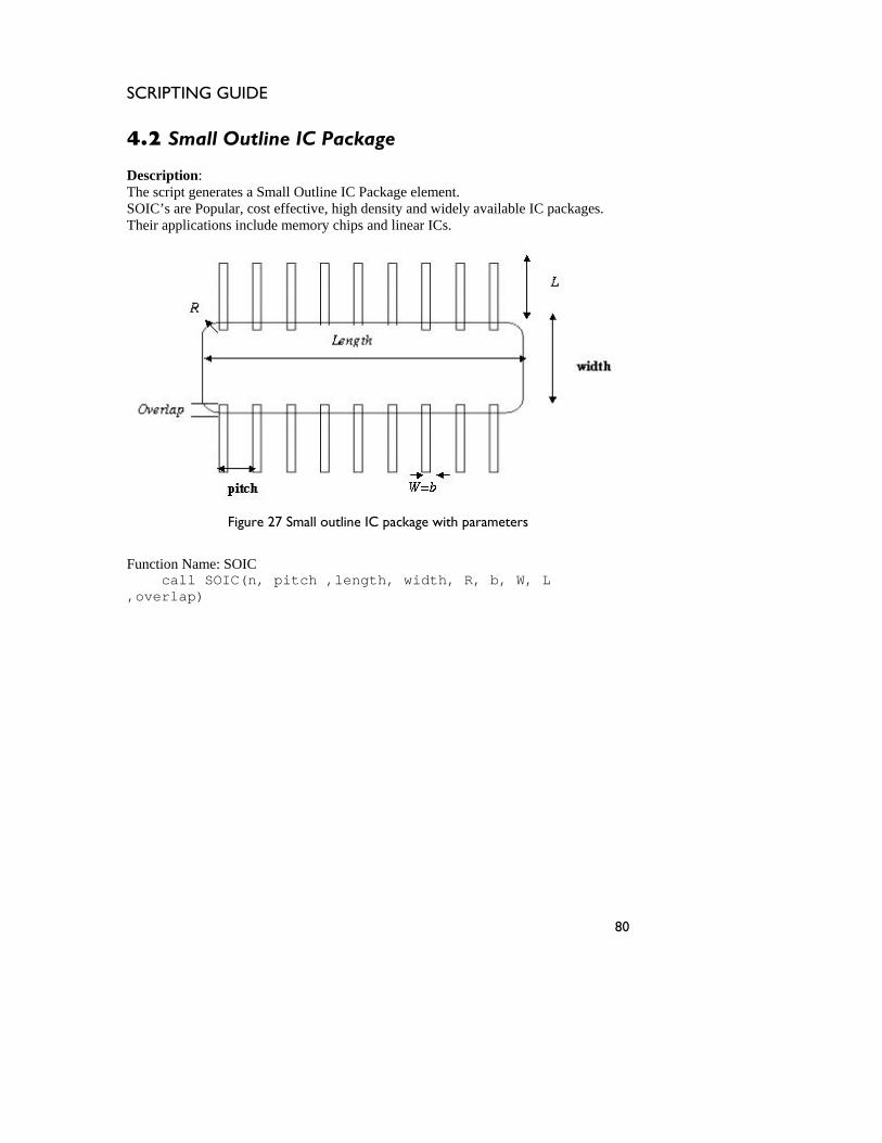
SCRIPTING GUIDE
4.2 Small Outline IC Package Description: The script generates a Small Outline IC Package element. SOIC’s are Popular, cost ilable IC packages.
pplications include memory chips and linear ICs. effective, high density and widely ava
Their a
Figure 27 Small outline IC package with parameters
Function Name: SOIC call SOIC(n, pitch ,length, width, R, b, W, L ,overlap)
80
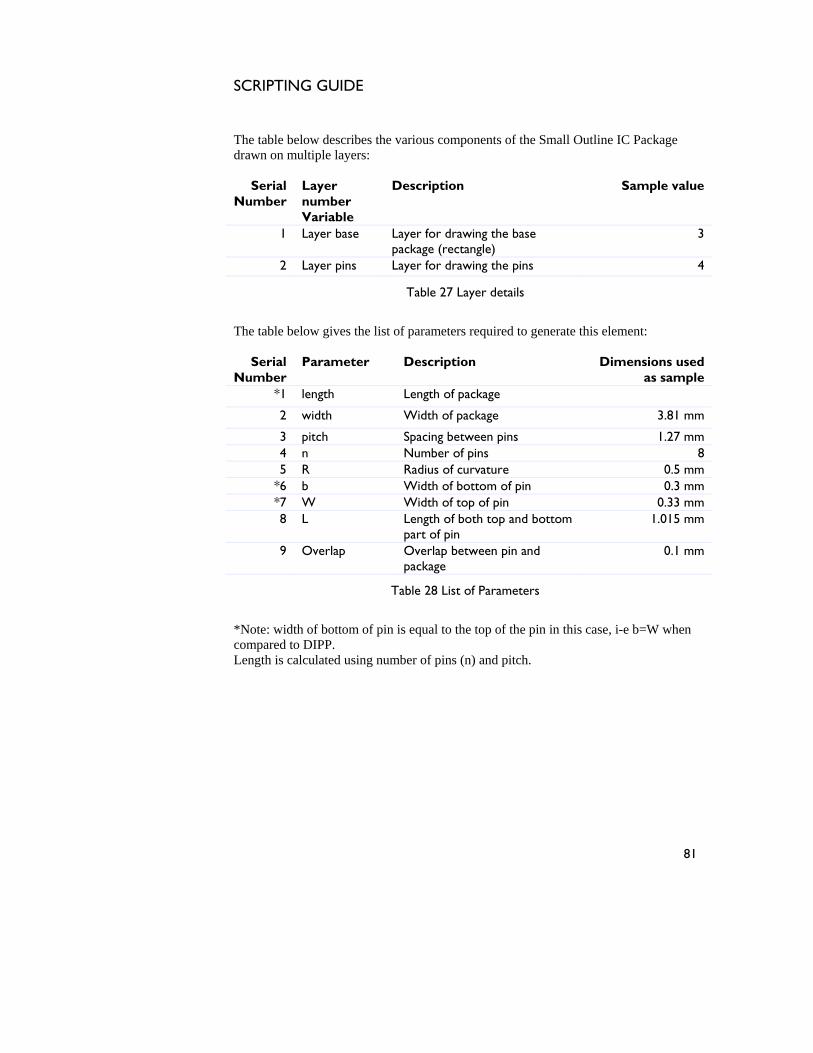
SCRIPTING GUIDE
The table below describes the various components of the Small Outline IC
rawn on multiple layers: Package
e
1 Layer base Layer for drawing the base package (rectangle)
3
d
Serial Layer Description Sample valuNumber number
Variable
2 Layer pins Layer for drawing the pins 4
Table 27 Layer details
Serial
Number Parameter Description Dimensions used
as sample *1 length Length of package
The table below gives the list of parameters required to generate this element:
2 width Width of package 3.81 mm
3 pitch Spacing between pins 1.27 mm 4 n Number of pins 8 5 R Radius of curvature 0.5 mm
*6 b Width of bottom of pin 0.3 mm *7 W Width of top of pin 0.33 mm 8 L Length of both top and bottom
part of pin 1.015 mm
9 Overlap Overlap between pin and package
0.1 mm
Table 28 List of Parameters
*Note: width of bottom of pin is equal to the top of the pin in this case, i-e b=W when compared to DIPP. Length is calculated using number of pins (n) and pitch.
81

SCRIPTING GUIDE
Figure 28 shows the Small Outline IC Package generated in IntelliMask with the
rror! Objects cannot be created from editing field codes.
e 28 C Package
The figure shows the two-layered m ach layer is represented by a different l k is drawn c left extreme as tstarting point.
sample dimensions shown in Table 28 E
Figur Small Outline I
ask layout wherein e co or. The mas onsidering the origin at the he
82
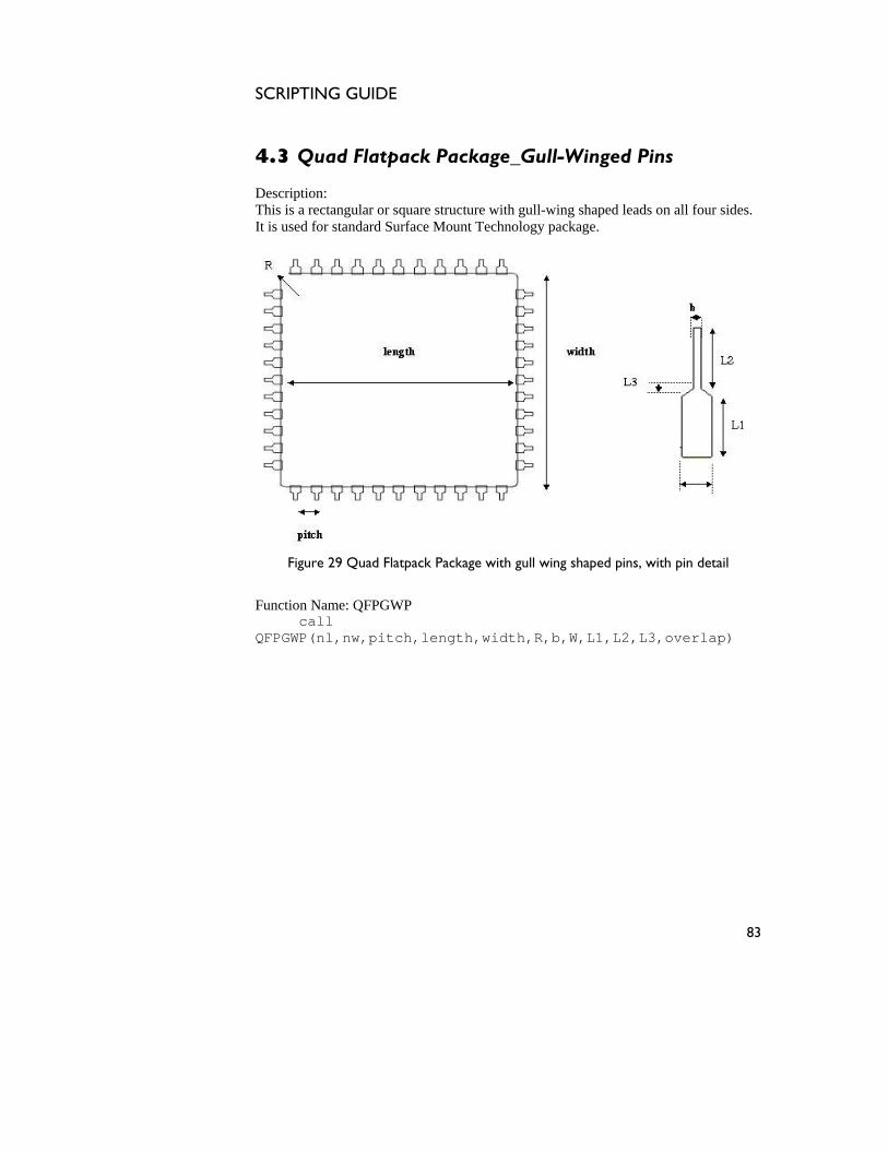
SCRIPTING GUIDE
4.3 Quad Flatpack Package_Gull-Winged Pins Description:This is a rect our sides. It is used for standard Surf
angular or square structure with gull-wing shaped leads on all f
ace Mount Technology package.
Figure 29 Quad Flatpack Package with gull wing shaped pins, with pin detail
Function Name: QFPGWP call QFPGWP(nl,nw,pitch,length,width,R,b,W,L1,L2,L3,overlap)
83
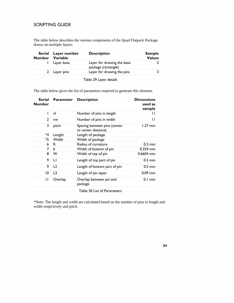
SCRIPTING GUIDE
he table below describes the various componeT nts of the Quad Flatpack Package
ple layers:
the base 2
drawn on multi
Serial Number
Layer number Variable
Description Sample Values
1 Layer base Layer for drawingpackage (rectangle)
2 Layer pins Layer for drawing the pins 3
Table 29 Layer details
The table below gives the list of parameters required to generate this element:
Serial Number
Parameter Description Dimensions used as sample
1 nl Number of pins in length 11
2 nw Number of pins in width 11
3 pitch Spacing between pins (center to center distance)
1.27 mm
*4 Length Length of package *5 Width Width of package 6 R Radius of curvature 0.3 mm 7 b Width of bottom of pin 0.254 mm 8 W Width of top of pin 0.6604 mm
9 L1 Length of top part of pin 0.5 mm
9 L2 0.5 mm Length of bottom part of pin
10 L3 Length of pin taper 0.09 mm
11 Overlap Overlap between pin and 0.1 mm package
Table 30 List of Parameters
*Note: The length and width are calculated based on the number of pins in length and width respectively and pitch.
84

SCRIPTING GUIDE
Figure 30 shows the QFP package with 44 pins for the sample dimensions shown iTable 30, as viewed in Inte
n lliMask.
bjects ted from editing fiel
Figure 30 Quad Flatpack Package
The above figure shows QFP layer represented by a different color. T ask orner of the base layer
Error! O cannot be crea d codes.
package with its eachhe origin of the m is located at the lower left c .
85
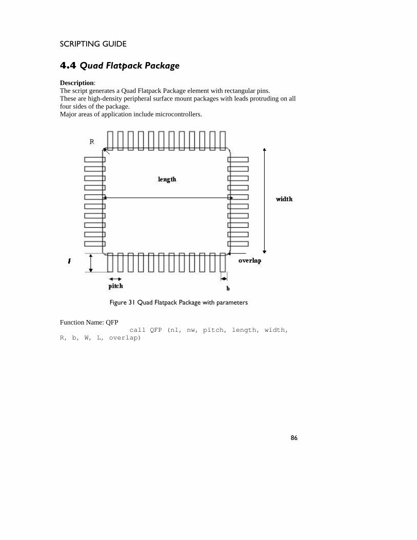
SCRIPTING GUIDE
4.4 Quad Flatpack Package
escription:
he script g s.
These are hi ding on all four sides of the package.
ajor areas of application include microcontrollers.
DT enerates a Quad Flatpack Package element with rectangular pin
gh-density peripheral surface mount packages with leads protru
M
Figure 31 Quad Flatpack Package with parameters
Function Name: QFP call QFP (nl, nw, pitch, length, width, R, b, W, L, overlap)
86
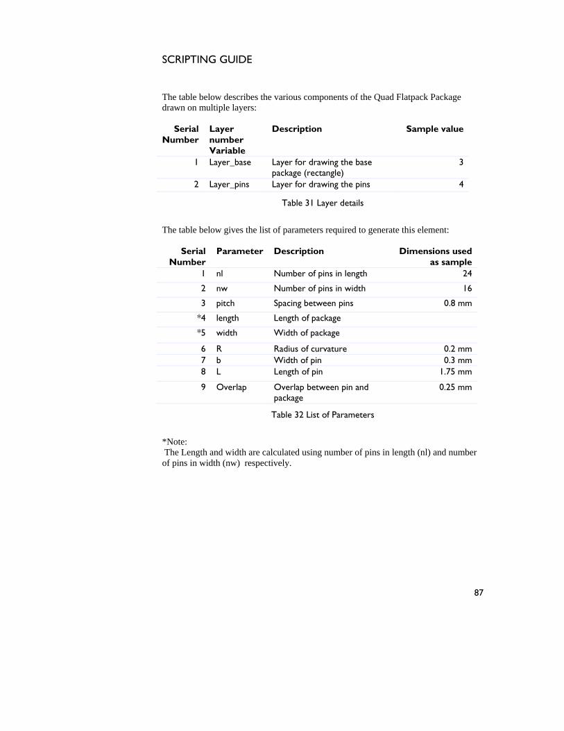
SCRIPTING GUIDE
The table below des
rawn on multiple lcribes the various components of the Quad Flatpack Package ayers:
1 Layer_base Layer for drawing the base package (recta
3
d
Serial Number
Layer number Variable
Description Sample value
ngle) 2 Layer_pins Laye ins 4 r for drawing the p
Table 31 Layer details
Serial Number
Parameter Description Dimensions used as sample
1 nl Number of pins in length 24
The table below gives the list of parameters required to generate this element:
2 nw Number of pins in width 16
3 pitch Spacing between pins 0.8 mm
*4 length Length of package
*5 width Width of package
6 R Radius of curvature 0.2 mm 7 b Width of pin 0.3 mm 8 L Length of pin 1.75 mm
9 Overlap Overlap between pin and package
0.25 mm
Table 32 List of Parameters
*Note: The Length and width are calculated using number of pins in length (nl) and number of pins in width (nw) respectively.
87

SCRIPTING GUIDE
Figure 32 shows an 80 pin QFP for the dimensions shown in Table 32, as viewed in IntelliMask.
nn rom edi
Figure 32
The abo fi QFP with sented by a differeThe origin of the mask is located ft corner of the base layer.
Error! Objects ca ot be created f ting field codes.
Quad Flatpack Package
ve gure shows its each layer repreat the lower le
nt color.
88
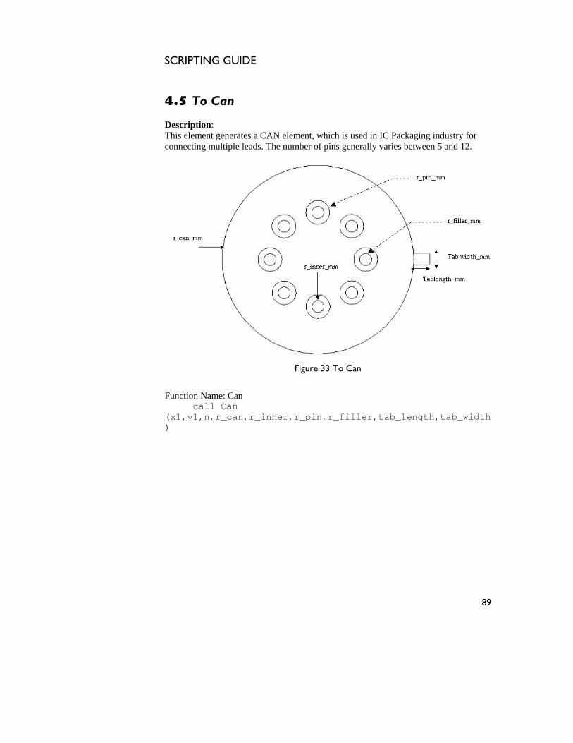
SCRIPTING GUIDE
4.5 To Can DescriptionThis elemen stry for connecting multiple leads. The nu lly varies between 5 and 12.
: t generates a CAN element, which is used in IC Packaging indu
mber of pins genera
Figure 33 To Can
Function Name: Can call Can (x1,y1,n,r_can,r_inner,r_pin,r_filler,tab_length,tab_width)
89
SCRIPTING GUIDE
he table below describes the various components of the T To Can drawn on multiple
Variable ple value
1 Layer_Can Layer number for drawing can
3
layers:
Serial Layer number Description SamNumber
2 Layer_Pin Layer number for drawing pins
4
3 Layer_Filler Layer number for drawing fillers
5
Table 33 Layer details
The table below gives the list of parameters required to generate this element:
Serial Number
Parameter Description Dimensions used as sample
1 n Number of pins 8
2 r_can_mm Outer radius of can 3.875 mm 3 r_inner_mm Inner radius around
which the pins are placed
2.235 mm
4 r_pin_mm Pin radius 0.205 mm 5 r_filler_mm Radius of filler hole 0.305 mm 6 ta m b_length_mm Length of tab 0.690 m7 tab_width_mm Width of tab 0.690 mm
Table 34 List of Parameters
90

SCRIPTING GUIDE
The next figure depicts the CAN with 8 pins, generated in Intellimask with the sample
imensions shown in Table 34.
jects cannot be created from editing field codes.
Can
The figure shows a multilayered m layer is represented by a different color. The origin is at t ement.
d
Error! Ob
Figure 34 To
ask layout wherein each he center of the CAN el
91
SCRIPTING GUIDE
4.6 Perforated Rectangular Plate Description:The script g
enerates a Perforated Rectangular Plate element.
Figure 35 Perforated Rectangular Plate with parameters
Function Name: PRP Call PRP (Plate_width ,Plate height, Corner radius ,n_rows, n_columns, hole_width, hole_height)
92
SCRIPTING GUIDE
The table below gives the layer details of the perforated plate:
Variable
Serial Number
Layer number
Description Sample value
1 Layer_plate Layer number to draw plate
3
Table 35 Layer details
Description Dimensions used as
e plate 200 µm
The table below gives the list of parameters required to generate this element:
Serial ParameterNumber sample
1 Plate_width Width of th
2 Plate_height Height of the plate 150 µm
3 Corner_radius Radius of curvature of 5 µm plate
4 n_rows Number of perforations 9 in a row
5 n_columns Number of perforations in a column
6
6 hole_width Width of the perforation
10 µm
7 hole_height Height of the perforation
10 µm
Table 36 List of parameters
93

SCRIPTING GUIDE
Figure 36 shows the Perforated Rectangular Plate as seen in IntelliMask with the
Error! Objects cannot be created from editing field codes.
Figure ngular Plate
The mas s n considerin r left corner as the starting
sample dimensions specified in Table 36.
36 Perforated Recta
k i draw g the origin located at the lowepoint.
94
SCRIPTING GUIDE
Elec ts
.1 Area-Perimeter Dielectric Isolation Test Structure
The APTEST element generates an area-perimeter test structure that can be used to test the dielectric properties of the isolation layer between the first electrical connect layer and the substrate. It can also be used to characterize electrical resistance. Electrical pads are connected to both the ends of the serpentine structure.
5 trical and mechanical test elemen
5(APTEST)
Description:
Figure 37 Area-Perimeter Dielectric Isolation Test Structure with parameters
Function Name: Aptest call Aptest(width, height, length, nw)
95
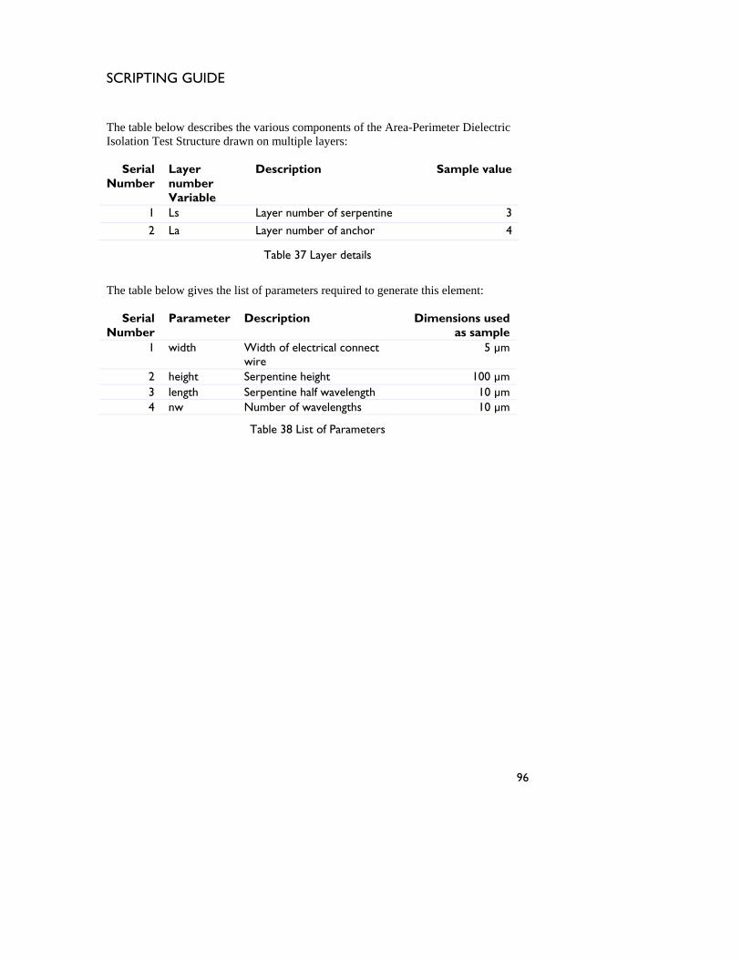
SCRIPTING GUIDE
he table below describes the various components of the ArT ea-Perimeter Dielectric
Isolation Test Structure drawn on multiple layers:
Serial Number
Layer number Variable
Description Sample value
1 Ls Layer number of serpentine 3
2 La Layer number of anchor 4
Table 37 Layer details
The table below gives the list of parameters required to generate this element:
Serial Number
Parameter Description Dimensions used as sample
1 width Width of electrical connect wire
5 µm
2 height Serpentine height 100 µm 3 length Serpentine half wavelength 10 µm 4 nw Number of wavelengths 10 µm
Table 38 List of Parameters
96

SCRIPTING GUIDE
The next figure shows the Area-Perimeter Dielectric Isolation Test Structure generated in IntelliMask with the values from Table 38.
n from editing field
rea-Perimeter Die tructure
Figure 3 h the Area-Perim cture with two of its layers re s d by different c sk is located at the lowleft corne of t rpentine structure.
Error! Objects ca not be created codes.
Figure 38 A lectric Isolation Test S
8 s ows eter Dielectric Isolation Test Strupre ente olors. The origin of the ma er r he se
97
SCRIPTING GUIDE
5.2 Crossover Test Structure Element
escription: The script generates a cros
sover test structure that can be used to test lectrical int ctural
layers 2 to cr 2 is anchored to the sub added to the
ires to allow electrical probing of the test structures. The structure below shows two
De erconnection of standard conducting lines using bridges on stru
oss over lines on structural layer 1. The wire on structural layer strate everywhere except at the bridges. Pads are
whorizontal bridge (crossover) wires on structural layer 2 that cross the anchored underpass which is the vertical wire on structural layer 1.
Figure 39 Crossover Test Structure-2 Element with parameters
Function Name: coatst call coatst (p0width, p1width, p2width, p2length, p1length)
98
SCRIPTING GUIDE
he table below describes the various components of the CrT ossover Test Structure
Element drawn on multiple layers:
Serial Number
Layer number Variable
Description Sample value
1 L1 Electrical connect Layer 1
2 L2 First Structural Layer 2
3 L3 Second Structural Layer 3
4 L4 Third Layer 4
Table 39 Layer details
Serial
Number Parameter Description Dimensions used as
sample 1 p0width
Width of wire on first electrical connect layer
5µm
The table below gives the list of parameters required to generate this element:
2 p1width Width of wire on first structural layer
10 µm
3 p2width Width of wire on second structural layer, µm
10 µm
4 p2length Length of crossover structures 100 µm
5 p1length Length of underpass structure 100 µm
Table 40 List of Parameters
99

SCRIPTING GUIDE
The next figure shows the Crossover Test Structure Element in Intellimask with the sample dimensions shown in Table 40.
n rom editing field co
40 Cros
The figure o ultilayered m represented by a different c rigin for the ft side pads of the crossover s ctu evident from
Error! Objects can ot be created f des.
Figure sover Test Structure-2 Element
sh ws a m ask layout with each layer is olor. The o structure is located between letru res as the figure.
100
SCRIPTING GUIDE
5.3 Crossover Test Structure Element
escription: The script generates a crossover test structure that c
an be used to test lectrical int ctural
layers 2 to cr r 2 is anchored to the sub dded to the
ires to allow electrical probing of the test structures. The structure below shows a
De erconnection of standard conducting lines using bridges on stru
oss over lines on structural layer 1. The wire on structural layestrate everywhere except at the bridges. Pads are a
whorizontal bridge (crossover) wire on structural layer 2 that crosses the anchored underpass, vertical wire on structural layer 1.
Figure 41 Crossover Test Structure Element with parameters
Function Name: cotest call cotest (p1width,p2width,p2length, p1length)
101
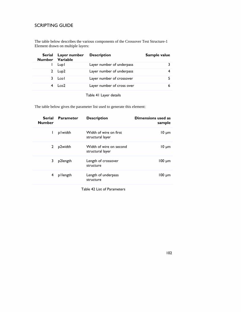
SCRIPTING GUIDE
he table below describes the various components of the Crossover TestT Structure-1
3
Element drawn on multiple layers:
Serial Layer number Description Sample valueNumber Variable
1 Lup1 Layer number of underpass
2 Lup2 Layer number of underpass 4
3 Lco1 Layer number of crossover 5
4 Lco2 Layer number of cross over 6
Table 41 Layer details
The table below gives the parameter list used to generate this element:
Serial Number
Parameter Description Dimensions used as sample
Width of wire on first 10 µm 1 p1width structural layer
2 p2width Width of wire on second structural layer
10 µm
3 p2length Length of crossover structure
100 µm
4 p1length Length of underpass structure
100 µm
Table 42 List of Parameters
102

SCRIPTING GUIDE
The next figure depicts the Crossover Test Structure-1 Element as viewed in Intellimask with the sample dimensions mentioned in Table 42.
r ot m editing field cod
2 Crossover Te
The figure show ultilayered mas represented by different color. The origin for the structure is e lower left corner of the pad of the crossover structure.
Er or! Objects cann be created fro es.
Figure 4 st Structure-1 Element
s a m k layout with each layer is a located at th
103
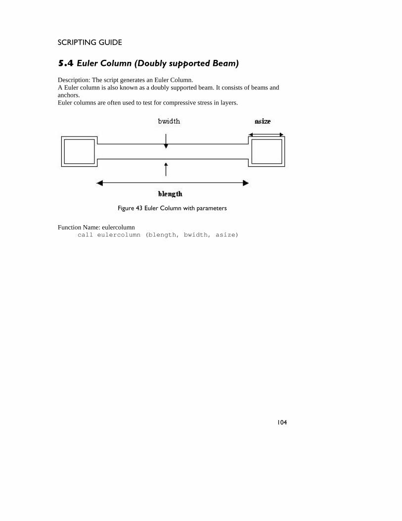
SCRIPTING GUIDE
5.4 Euler Column (Doubly supported Beam)
escription: The script generates an E
uler Column. Euler colu ams and
anchors. Euler columns ar
DA mn is also known as a doubly supported beam. It consists of be
e often used to test for compressive stress in layers.
Figure 43 Euler Column with parameters
Function Name: eulercolumn call eulercolumn (blength, bwidth, asize)
104
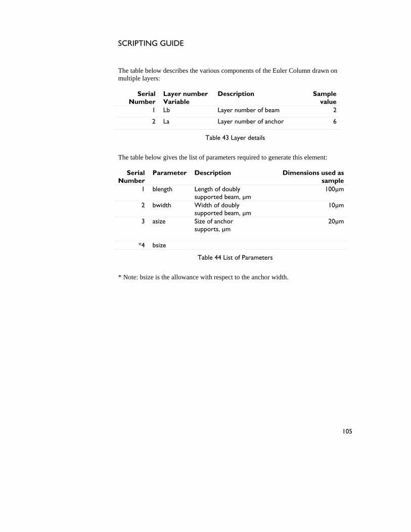
SCRIPTING GUIDE
The table below describes the various components of the Euler Column drawn on
ultiple layers: m
Serial Layer number Description Sample Number Variable value
1 Lb Layer number of beam 2
2 La Layer number of anchor 6
Table 43 Layer details
The table below gives the list of parameters required to generate this element:
sample 1 blength Length of doubly
supported beam, µm 100µm
Serial
Number Parameter Description Dimensions used as
2 bwidth Width of doubly supported beam, µm
10µm
3 asize Size of anchor supports, µm
20µm
*4 bsize
Table 44 List of Parameters
* Note: bsize is the allowance with respect to the anchor width.
105

SCRIPTING GUIDE
The next figure depicts the Euler column as viewed in Intellimask with the sampledimensions shown in Table
44.
r jects cann rom editing f
Euler Column (Doubly Supported Beam)
The figure w ultilayered m layer is represente y a different col r. The mask is drawn c e starting point.
E ror! Ob ot be created f ield codes.
Figure 44
shoo
s a m ask layout wherein each onsidering the origin as th
d b
106
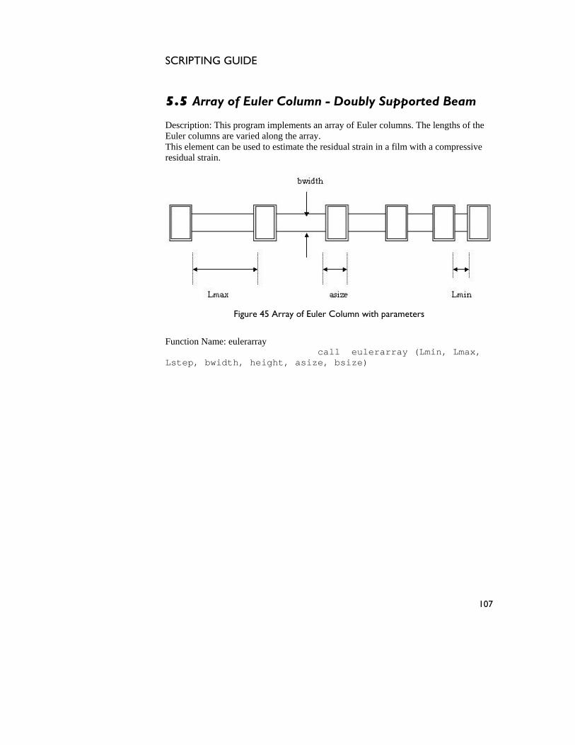
SCRIPTING GUIDE
5.5 Array of Euler Column - Doubly Supported Beam Description: This program implements an array of Euler columns. The lengths o
uler columns are varied along the arrf the
ay. with a compressive
EThis element can be used to estimate the residual strain in a filmresidual strain.
Figure 45 Array of Euler Column with parameters
Function Name: eulerarray call eulerarray (Lmin, Lmax, Lstep, bwidth, height, asize, bsize)
107
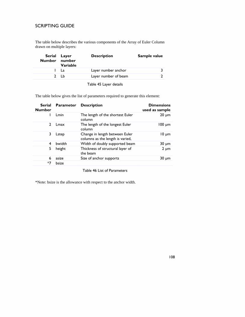
SCRIPTING GUIDE
he table below describes the various components of the ArrayT of Euler Column
iple layers:
Serial Number
Layer number Variable
Description Sample value
1 La Layer number anchor 3
drawn on mult
2 Lb Layer number of beam 2
Table 45 Layer details
The table below gives the list of parameters required to generate this element:
Serial Number
Parameter Description Dimensions used as sample
1 Lmin The length of the shortest Euler column
20 µm
2 Lmax The length of the longest Euler column
100 µm
3 Lstep Change in length between Euler columns as the length is varied,
10 µm
4 bwidth Width of doubly supported beam 30 µm 5 height Thickness of structural layer of
the beam 2 µm
6 30 µm asize Size of anchor supports *7 bsize
Table 46 List of Parameters
th respect to the anchor width. *Note: bsize is the allowance wi
108

SCRIPTING GUIDE
The next figure shows an array of 9 Euler Columns generated in IntelliMask with the length of the column decreasing gradually from the longest to the shortest length. The
ifference in lengths between two consecutive columns is the step length. The dim fied in Tab
Error! Obj be created from editing field codes.
Figu r Coulmn
Figure 46 shows the element w o layers represented by different colors. The origin of the element is located at the left end of the set of columns.
densions
are speci le 46.
ects cannot
re 46 Array of Eule
ith the tw
109

SCRIPTING GUIDE
5.6 Guckel Ring Test Structure Element
escription:
D
Figure 47 Guckel Ring Test Structure Element with parameters
Function Name: guckelring call guckelring(radius, bring, bbeam, asize)
110
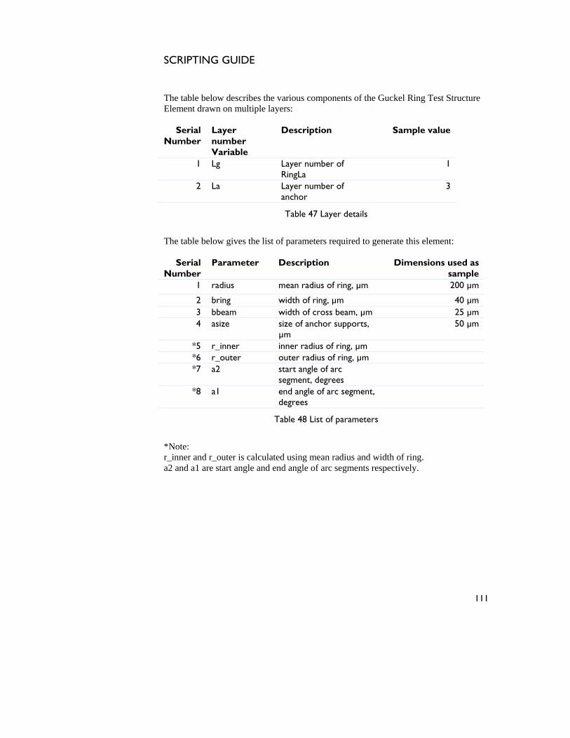
SCRIPTING GUIDE
The table below describes the various com
lement drawn on multiple layers: ponents of the Guckel Ring Test Structure
1 Lg Layer number of RingLa
1
E
Serial Number
Layer number Variable
Description Sample value
2 La anchor
3 Layer number of
Table 47 Layer details
The table below gives the list of parameters required to generate this element:
Serial Number
Parameter Description Dimensions used as sample
1 radius mean radius of ring, µm 200 µm
2 bring width of ring, µm 40 µm 3 bbeam width of cross beam, µm 25 µm 4 asize size of anchor supports,
µm 50 µm
*5 r_inner inner radius of ring, µm *6 r_outer outer radius of ring, µm *7 a2 start angle of arc
segment, degrees
*8 a1 end angle of arc segment, degrees
Table 48 List of parameters
*Note: r_inner and r_outer is calculated using mean radius and width of ring. a2 and a1 are start angle and end angle of arc segments respectively.
111

SCRIPTING GUIDE
The next figure shows the Guckel Ring Test Structure Element with dimensions as specified in Table 48.
bjects c d from editing fie
re 48 Guckel Ring Test Structure Element
Figure 4 h he element w ented by different colo The mask is dr nsidering the t.
Error! O annot be create ld codes.
Figu
8 saw
ows tn co
ith two of its layers represorigin as the starting poin
rs.
112
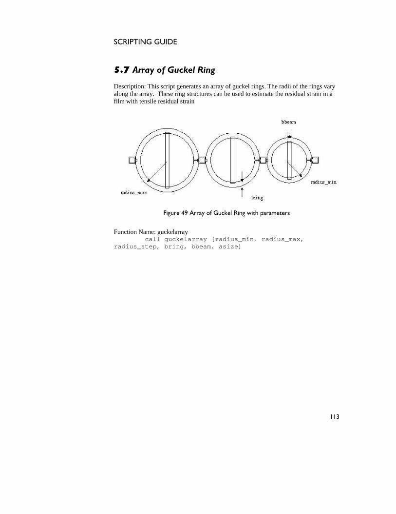
SCRIPTING GUIDE
5.7 Array of Guckel Ring
escription: This script generates an array of guckel rings. The radii of tD he rings vary e residual strain in a
along the array. These ring structures can be used to estimate thfilm with tensile residual strain
Figure 49 Array of Guckel Ring with parameters
Function Name: guckelarray call guckelarray (radius_min, radius_max, radius_step, bring, bbeam, asize)
113
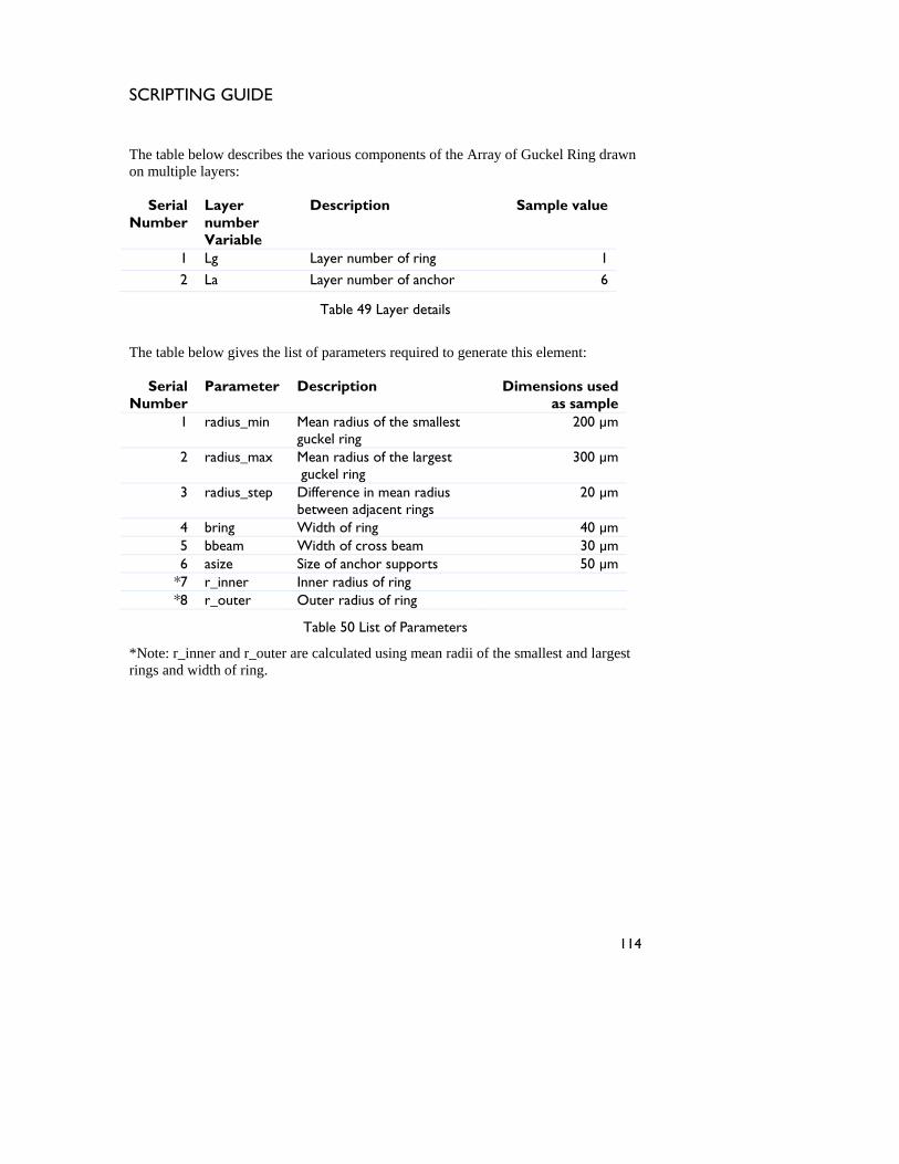
SCRIPTING GUIDE
he table below describes the various components of thT e Array of Guckel Ring drawn
mber of ring 1
on multiple layers:
Serial Layer Description Sample value Number number
Variable 1 Lg Layer nu
2 La Layer number of anchor 6
Table 49 Layer details
The table below gives the list of parameters required to generate this element:
Serial Number
Parameter Description Dimensions used as sample
1 radius_min Mean radius of the smallest guckel ring
200 µm
2 radius_max Mean radius of the largest guckel ring
300 µm
3 radius_step Difference in mean radius between adjacent rings
20 µm
4 bring Width of ring 40 µm 5 bbeam Width of cross beam 30 µm 6 asize Size of anchor supports 50 µm
*7 r_inner Inner radius of ring *8 r_outer Outer radius of ring
Table 50 List of Parameters
*Note: r_inner an lest and largest ngs and width of ring.
d r_outer are calculated using mean radii of the smalri
114

SCRIPTING GUIDE
The next figure shows the IntelliMask generated Guckel Array, containing 6 Rings with the radius of the rings gradually decreasing from the maximum to minimum
dius. The figure shown the sample dimensions specified in Table 50.
be created from editing field codes.
Figure 50 Array of Guckel Ring
Figure 5 h he element with its two layers represented by differen olors. The origin o e ent is located at the center of the ring with the maxim radius.
ra
Error! Objects cannot
0 s ows t t cf th elem um
115
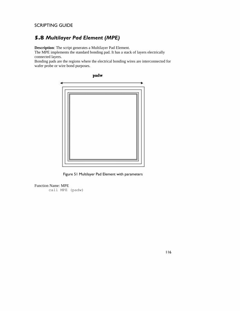
SCRIPTING GUIDE
5.8 Multilayer Pad Element (MPE) Description
The MPE im trically connected layers.
pads are the regions where the electrical bonding wires are interconnected for
: The script generates a Multilayer Pad Element. plements the standard bonding pad. It has a stack of layers elec
Bonding wafer probe or wire bond purposes.
Figure 51 Multilayer Pad Element with parameters
Function Name: MPE call MPE (padw)
116
SCRIPTING GUIDE
he table below describes the various cT omponents of the MultiLayer Pad Element
1 Lp1 1
drawn on multiple layers:
Serial umber
Layer number Variable
Sample value N
2 Lp2 2 3 Lp3 3
4 Lp4 4
5 Lp5 5
6 Lp6 6
Table 51 Layer details
Lp1 to Lp6 are the layer numbers of the 6 layers of the element. The table below gives the list of parameters required to generate this element:
Serial Number
Parameter Description Dimensions used as sample
1 padw Width of the exterior most pad
118 µm
*2 Width of 2 to 6 layers
Table 52 List of parameters
*The width of the subsequent 5 inner layers is calculated as per MUMPS standard.
117

SCRIPTING GUIDE
The next figure shows the MPE with the sample dimensions as shown in Table 52,
enerated in IntelliMask. n from editi
Figure 52 Multil
The above figure shows a multi rein each of the 6 layers is
presented by a different color. The layers 2 and 4, being overlapped by layers 3 and left
gError! Objects ca not be created ng field codes.
ayer Pad Element
layered mask layout where5 respectively are not visible. The origin for the element is located at the lowerorner of the exterior most pad. c
118
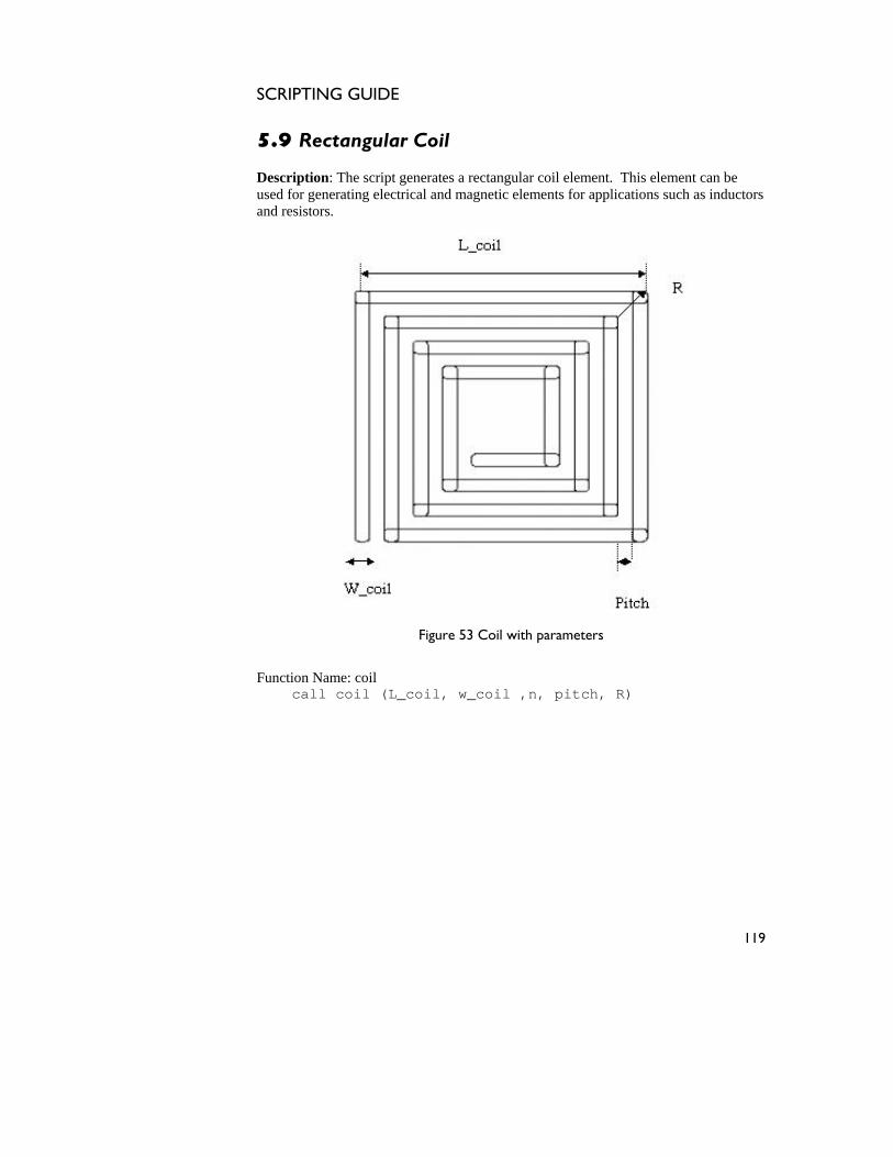
SCRIPTING GUIDE
5.9 Rectangular Coil
escription: The script ge
nerates a rectangular coil element. This element can be sed for gen inductors
and resistors
Du erating electrical and magnetic elements for applications such as
.
Figure 53 Coil with parameters
Function Name: coil call coil (L_coil, w_coil ,n, pitch, R)
119
SCRIPTING GUIDE
The table below gives the layer number variable of the coil drawn:
Serial Number
Layer number Variable
Description Sample Values
1 Layer_coil layer to draw the coil 7
Table 53 Layer details
The table below gives the list of parameters required to generate this element:
Serial Number
Parameter Description Dimensions used as sample
1 L_coil Outer length of the coil 200 µm
2 w_coil Width of the coil strand 10 µm
3 n Number of turns of the coil 4 4 pitch pitch of the coil 10 µm 5 R curvature of the coil
corners 3 µm
Table 54 List of Parameters
120

SCRIPTING GUIDE
Figure 54 shows the coil structure with the sample dimensions as shown in Table 54, generated in IntelliMask.
Error! Objects cannot be created from editing field codes.
l
ering the origin at the lower left corner as the starting point.
Figure 54 Coi
The mask is drawn consid
121

SCRIPTING GUIDE
122
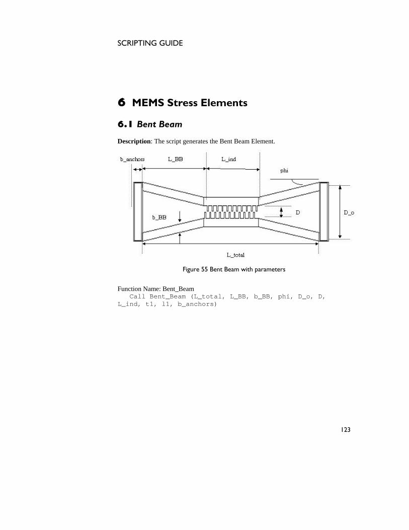
SCRIPTING GUIDE
6 MEMS Stress Elements
Description: The script generates the Bent Beam Element.
6.1 Bent Beam
Figure 55 Bent Beam with parameters
Function Name: Bent_Beam Call Bent_Beam (L_total, L_BB, b_BB, phi, D_o, D, L_ind, t1, l1, b_anchors)
123
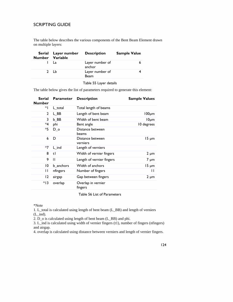
SCRIPTING GUIDE
The table below describes the
n multiple layers: various components of the Bent Beam Element drawn
anchor
o
Serial Number
Layer number Variable
Description Sample Value
1 La Layer number of 6
2 Lb Layer num er of 4 bBeam
Table 55 Layer details
Number Values
*1 L_total Total length of beams
The table below gives the list of parameters required to generate this element:
Serial Parameter Description Sample
2 L_BB Length of bent beam 100µm
3 b_BB Width of bent beam 10µm *4 phi Bent angle 10 degrees *5 D_o Distance between
beams
6 D Distance between verniers
15 µm
*7 L_ind Length of verniers
8 t1 Width of vernier fingers 2 µm
9 l1 Length of vernier fingers 7 µm
10 b_anchors Width of anchors 15 µm 11 nfingers Number of fingers 11
12 airgap Gap between fingers 2 µm
*13 overlap Overlap in vernier fingers
Table 56 List of Parameters
*Note 1. L_total is calculated using length of bent beam (L_BB) and length of verniers (L_ind). 2. D_o is calculated using length of bent beam (L_BB) and phi. 3. L_ind is calculated using width of vernier fingers (t1), number of fingers (nfingers) and airgap. 4. overlap is calculated using distance between verniers and length of vernier fingers.
124

SCRIPTING GUIDE
The bent beam is shown in the figure below as generated in IntelliMask using the dimensions as specified in Table 56.
Error! Objects cannot be created from editing field codes.
Beam
The figure shows the mask layou n each of the two layers is represented by a different l raw e starting point
Figure 56 Bent
t wherei co or. The mask is d n considering the origin as th .
125
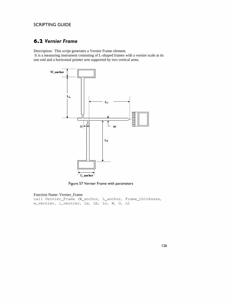
SCRIPTING GUIDE
6.2 Vernier Frame Description: It is a meas ale at its one end and a horizontal point rtical arms.
This script generates a Vernier Frame element. uring instrument consisting of L-shaped frames with a vernier sc
er arm supported by two ve
Figure 57 Vernier Frame with parameters
Function Name: Vernier_Frame call Vernier_Frame (W_anchor, L_anchor, Frame_thickness, w_vernier, l_vernier, La, Lb, Lc, W, O, n)
126
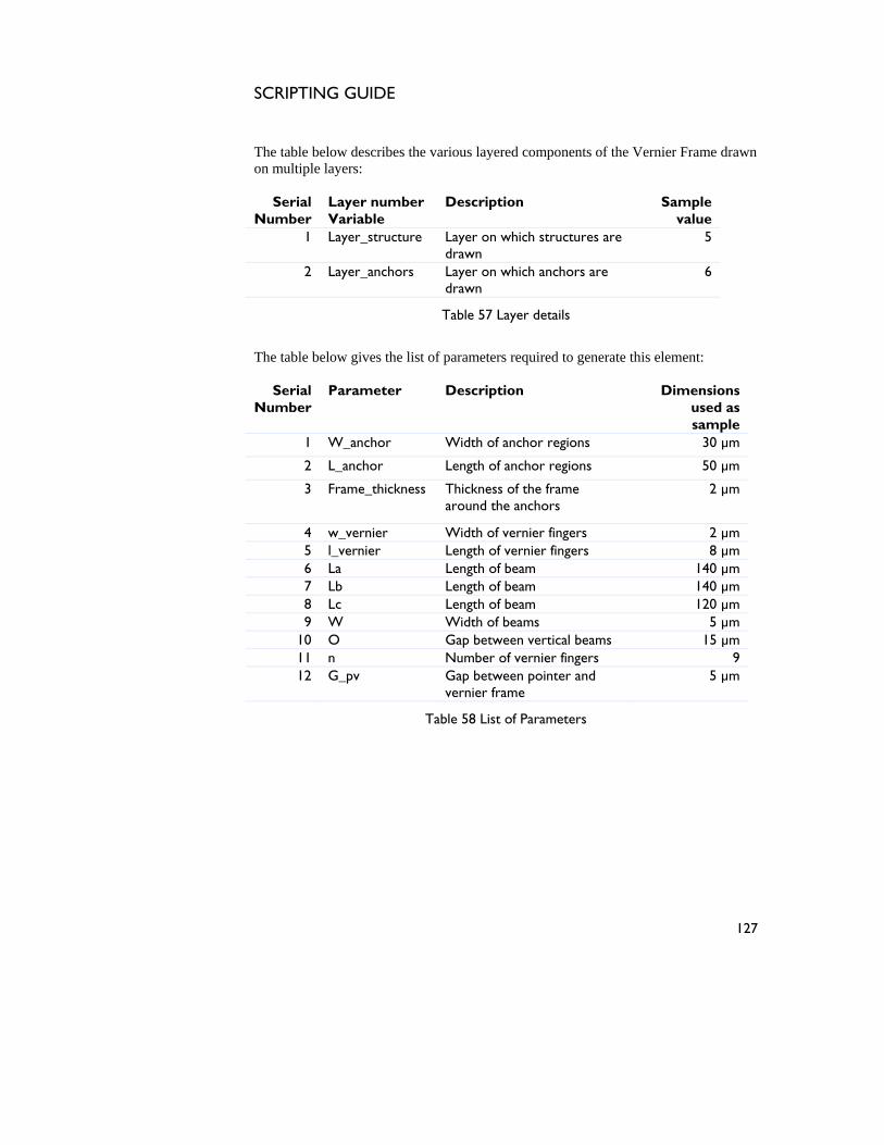
SCRIPTING GUIDE
Vernier Frame drawn
r number ble
Description Sample value
yer_structure Layer on which structures are 5
The table below describes the various layered components of theon multiple layers:
Serial umber
LayeVariaN
1 Ladrawn
2 Layer_anchors Layer on which anchors are drawn
6
Table 57 Layer details
The table below gives the list of parameters required to generate this element:
Serial Number
Parameter Description Dimensions used as sample
1 W_anchor Width of anchor regions 30 µm
2 L_anchor Length of anchor regions 50 µm
3 Frame_thickness Thickness of the frame 2 µm around the anchors
4 w_vernier Width of vernier fingers 2 µm 5 l_vernier Length of vernier fingers 8 µm 6 La Length of beam 140 µm 7 Lb Length of beam 140 µm 8 Lc Length of beam 120 µm 9 W Width of beams 5 µm
10 15 µm O Gap between vertical beams1 rs 9 1 n Number of vernier finge12 G_pv een pointer and 5 µm Gap betw
vernier frame
Table 58 List f Parameters o
127

SCRIPTING GUIDE
The nex below depicts iewed in Intellimask
mple dimensions shown in Table 58.
Error! Objects cannot be cre ted from editing field codes.
layout wherein each layer is represented by a ifferent color. The origin is located at lower-left end of the horizontal beam.
t figure the Vernier Frame as v with the sa
a
Figure 58 Vernier Frame
The figure shows a multilayered mask d
128
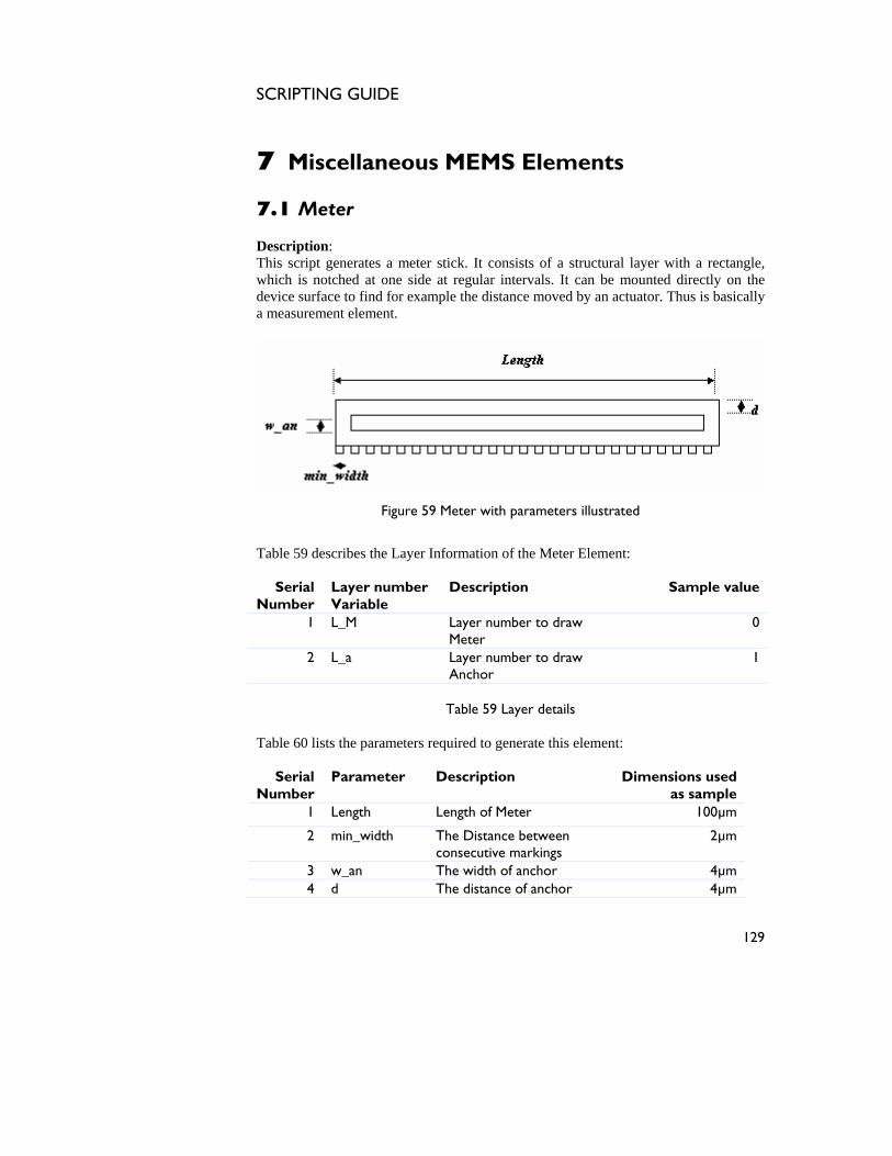
SCRIPTING GUIDE
7 Miscellaneous MEMS Elements
his script generates a meter stick. It consists of a structural layer with a rectangle, which is notched at one side at regular intervals. It can be mounted directly on the device surface to find for example the distance moved by an actuator. Thus is basically a measurement element.
7.1 Meter Description: T
Figure 59 Meter with parameters illustrated
Ta s f Meter Element:
SeriNumber
r number Variable
Sample valu
ble 59 de
cribes the Layer In ormation of the
al Laye Description e
1 L_M Layer number to draw Meter
0
2 L_a Layer number to draw 1 Anchor
Table 60 lists the parameters required to generate this element:
Serial Number
Parameter Description Dimensions used as sample
1 Length Length of Meter 100µm
Table 59 Layer details
2 min_width The Distance between consecutive markings
2µm
3 w_an The width of anchor 4µm 4 d The distance of anchor 4µm
129
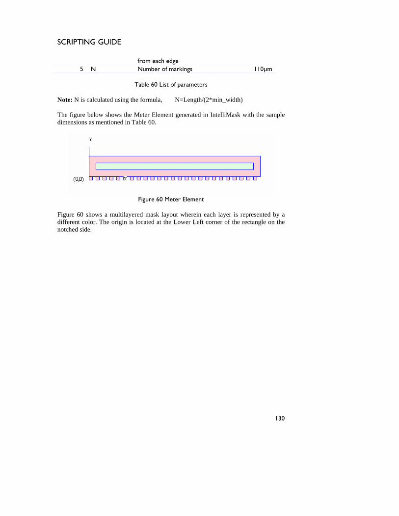
SCRIPTING GUIDE
fromNumber of markings
each edge 5 N 110µm
Table s
Note: N is ca l ng the for _width) The figure b s the Meter IntelliMask with the sadimensions a e ed in Table
60 List of parameter
lcu ated usi mula, N=Length/(2*min
elow show Element generated in mple s m ntion 60.
Figure 60 Meter Element
Figure 60 shows a multilayered mask lay wherein each layer is represented by a out
different color. The origin is located at the Lower Left corner of the rectangle on the notched side.
130
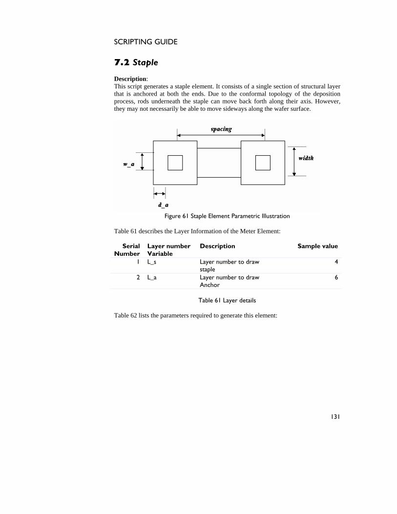
SCRIPTING GUIDE
7.2 Staple
escription: erates a staple element. It consists of a single section of structural layer
forth along their axis. However,
DThis script genthat is anchored at both the ends. Due to the conformal topology of the deposition process, rods underneath the staple can move back they may not necessarily be able to move sideways along the wafer surface.
Figure 61 Sta Illustration
Table 61 describes the Layer Information of the Meter Element:
Serial Number
Layer number Variable
Description Sample value
1 L_s Layer number to draw staple
4
ple Element Parametric
2 L_a Layer number to draw Anchor
6
Table 61 Layer details
Table 62 lists the parameters required to generate this element:
131
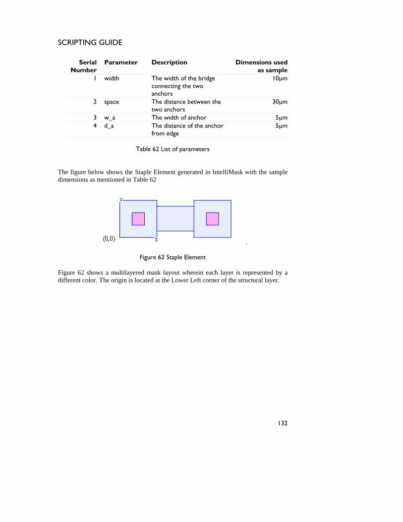
SCRIPTING GUIDE
Tab
The figu b shows the Sta liMask with th le dimensi a ntioned in Tab
le 62 List of parameters
re elow ple Element generated in Intel e sampons s me le 62
.
Figure 62 Staple Element
Figure 62 shows a multilayered mask layout wherein each layer is represented by a different color. The origin is located at the Lower Left corner of the structural layer.
Serial Number
Parameter Description Dimensions used as sample
1 widconnect he two
10µm th The width of the bridge ing t
anchors 2 space The distance between the
30µm
two anchors3 w_a The width of anchor m 5µ4 d_a The distance of the anchor m
from edge 5µ
132
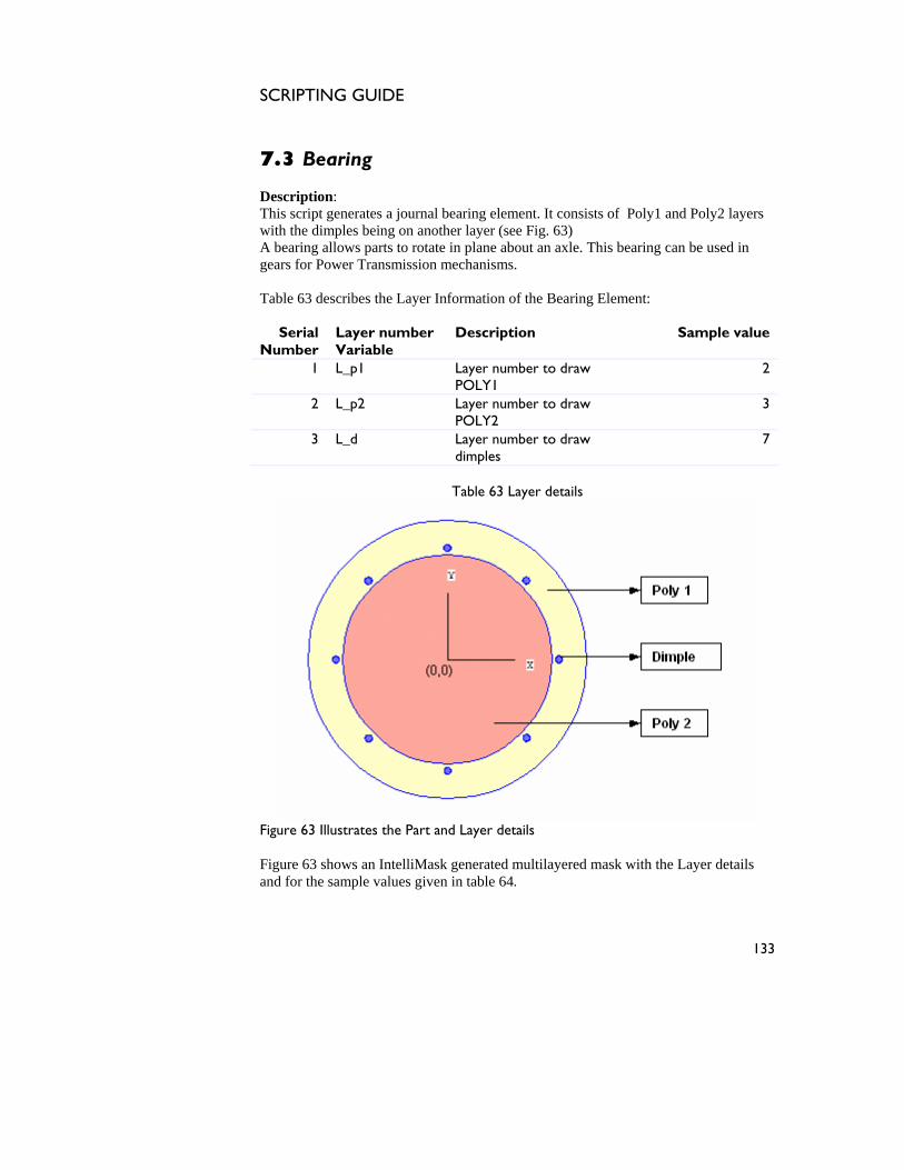
SCRIPTING GUIDE
7.3 Bearing
g. 63) bearing allows parts to rotate in plane about an axle. This bearing can be used in
Ta s f Bearing Element:
SeriNumber
number Variable
Sample valu
Description: This script generates a journal bearing element. It consists of Poly1 and Poly2 layers with the dimples being on another layer (see FiAgears for Power Transmission mechanisms.
ble 63 de
cribes the Layer In ormation of the
al Layer Description e
1 L_p1 Layer number to draw POLY1
2
2 L_p2 Layer number to draw 3 POLY2
3 L_d Layer num er to draw dimples
7 b
Table 63 Layer details
Figure 63 Illustrates the Part and Layer details Fi ure 63 shows an IntelliMask generated multilayered mask with the Layer details a r th
gnd fo e sample values given in table 64.
133
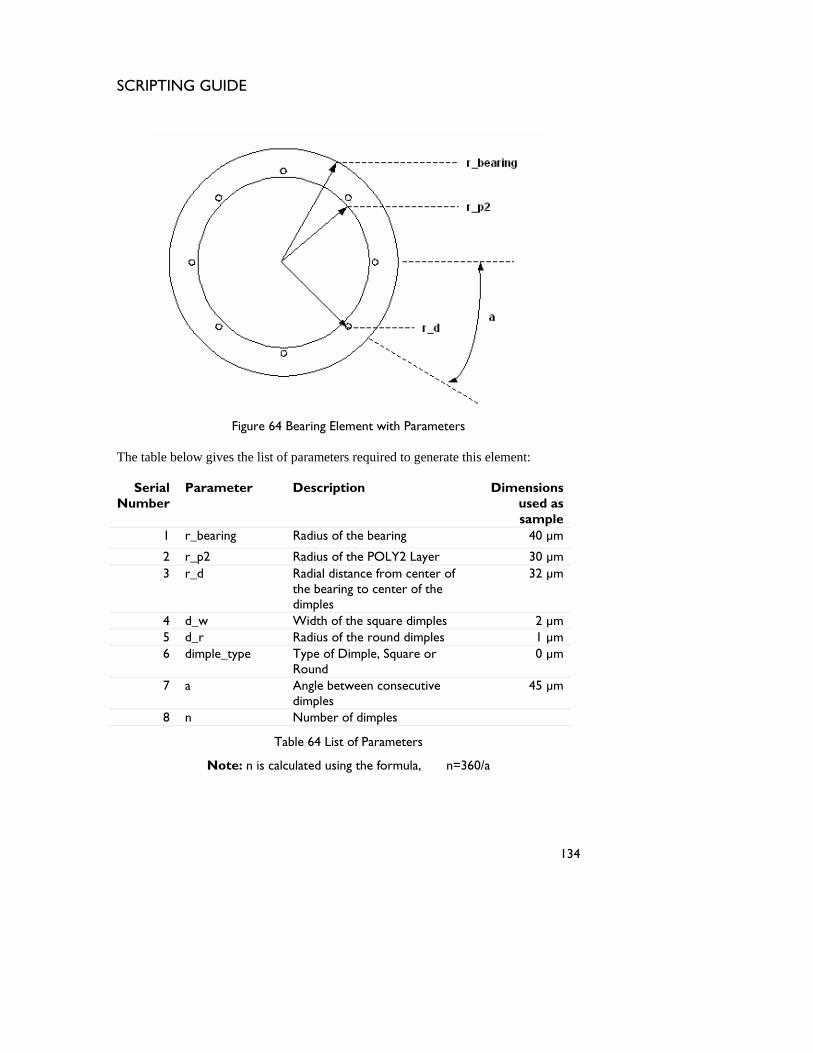
SCRIPTING GUIDE
Figure 64 Bear
The table l s the list of par ement:
SeriaNumbe
P meter De Dimensions used as sample
r Rad 40 µm
ing Element with Parameters
be ow give ameters required to generate this el
l r
ara scription
1 _bearing ius of the bearing
2 r_p2 r 30 µm Radius of the POLY2 Laye3 r_d Radial distance from center of
the bearing to center of the dimples
32 µm
4 d_w Width of the square dimples 2 µm 5 d_r Radius of the round dimples 1 µm 6 dimple_type Type of Dimple, Square or
Round 0 µm
7 a Angle between consecutive dimples
45 µm
8 n Number of dimples
Table 64 List of Parameters
Note: n is calculated using the formula, n=360/a
134
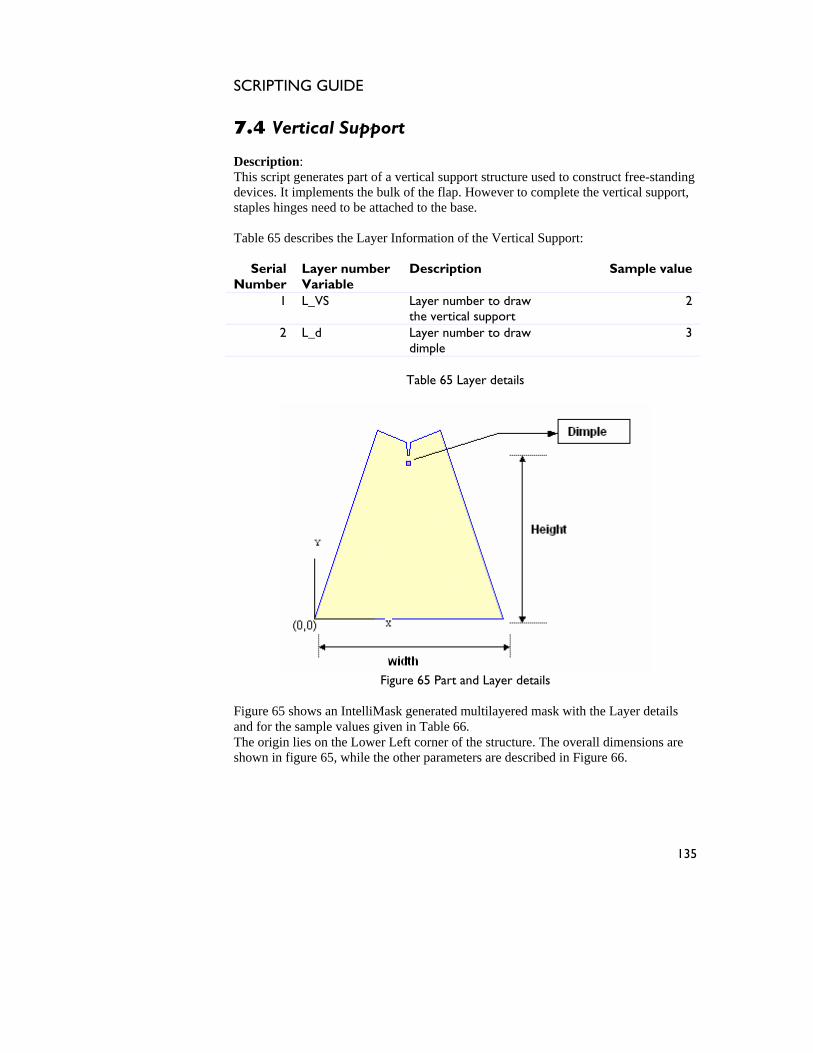
SCRIPTING GUIDE
7.4 Vertical Support
f the flap. However to complete the vertical support,
staples hinges need to be attached to the ba .
able 65 describes the Layer Information of the Vertical Support:
Numbeber
le Description Sample value
1 L_VS to draw 2
Description: This script generates part of a vertical support structure used to construct free-standingdevices. It implements the bulk o
se T
Serial r
Layer numVariab
Layer number the vertical support
2 L_d 3 Layer number to drawdimple
Table 65 Layer details
Figure 65 Part and Layer details
Figure 65 shows an IntelliMask generated multilayered mask with the Layer details and for the sample values given in Table 66. The origin lies on the Lower Left corner of the structure. The overall dimensions are shown in figure 65, re 66.
while the other parameters are described in Figu
135
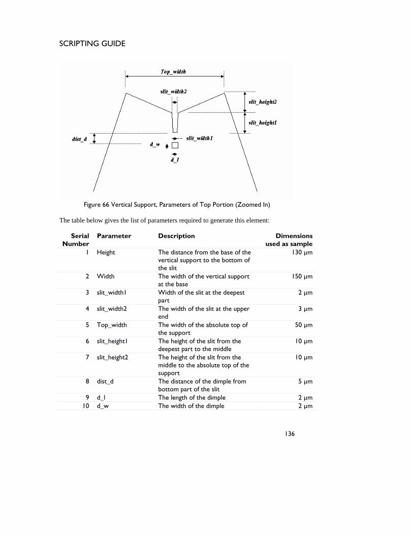
SCRIPTING GUIDE
Figure 66 Vertical Support, Parameters of Top Portio
The table b lo par t:
Serial Numbe
Parameter Dimensions used as sa
1 Height from the base of the f
130 µm
n (Zoomed In)
ameters required to generatee w gives the list of this elemen
Descriptionr mple
The distancevertical support to the bottom othe slit
2 Width support 15The width of the vertical at the base
0 µm
3 slit_width1 e slit at the deepest 2 µm Width of thpart
4 slit_width2 idth of the slit at the upper 3 µm The wend
5 Top_width he absolute top of the support
50 µm The width of t
6 slit_height1 rom the deepest part to the middle
10 µm The height of the slit f
7 slit_height2 The height of the slit from the middle to the absolute top of the support
10 µm
8 dist_d The distance of the dimple from bottom part of the slit
5 µm
9 d_l The length of the dimple 2 µm 10 d_w The width of the dimple 2 µm
136

SCRIPTING GUIDE
11 d_r The radius of dimple 1 µm ound 1 µm 12 dimple_type Type of Dimple, Square or R
Table 66 List of Parameters
137
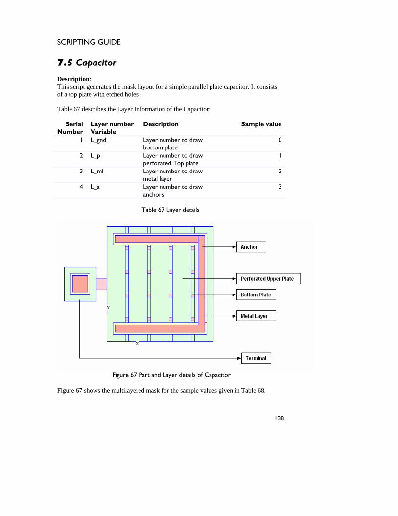
SCRIPTING GUIDE
7.5 Capacitor
escription:
Table 67 describes the Layer Information of e Capacitor:
Serial Number
Layer numVariable
Sample value
DThis script generates the mask layout for a simple parallel plate capacitor. It consists of a top plate with etched holes
th
ber Description
1 L_gnd Layer number to draw bottom plate
0
2 L_p Layer number to draw perforated Top plate
1
3 L_ml Layer number to draw metal layer
2
4 L_a Layer number to draw anchors
3
Table 67 Layer details
Figure 67 Part and Layer details of Capacitor
Figure 67 shows the multilayered mask for the sample values given in Table 68.
138
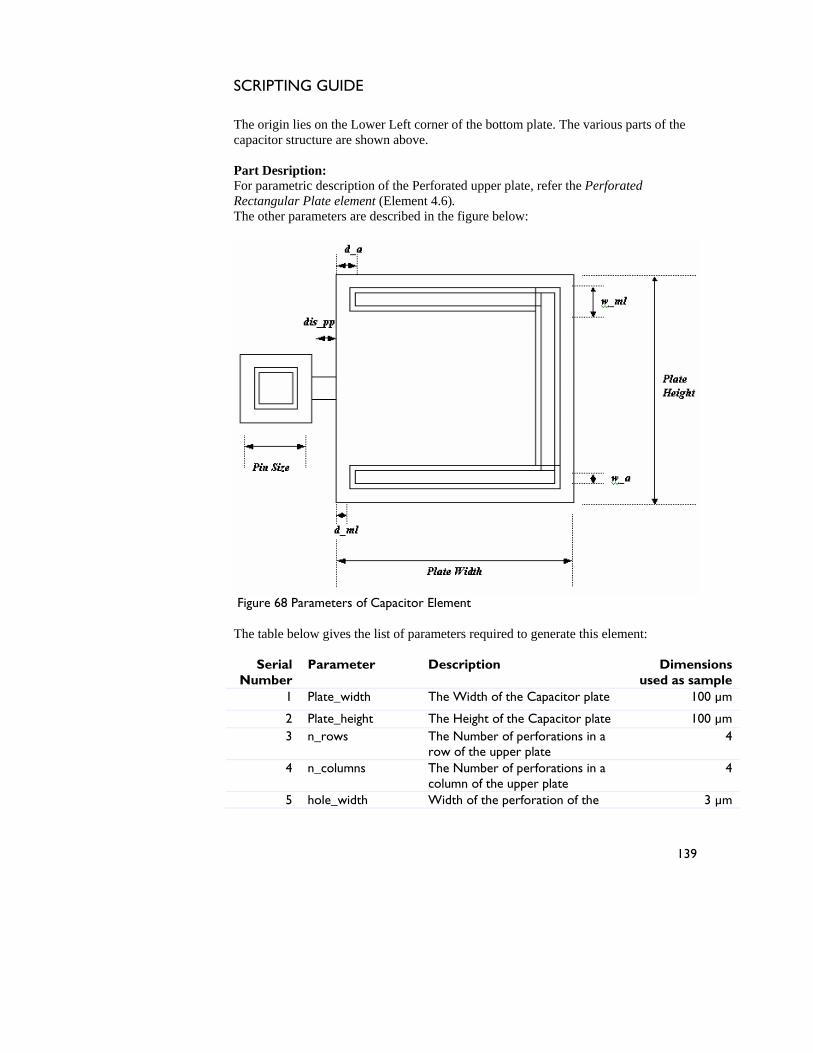
SCRIPTING GUIDE
The origin lies on the Lower Left corner of the bottom plate. The vaapacitor structure are shown above.
rious parts of the c Part Desription: For parametric description of the Perforated upper plate, refer the Perforated Rectangular Plate element (Element 4.6). The other parameters are described in the figure below:
Figure 68 Parameters of Capacitor Element
this element:
_width 10
he table below gives the list of parameters required to generateT
Serial
Number Parameter Description Dimensions
used as sample 1 Plate The Width of the Capacitor plate 0 µm
2 Plate_height tor plate 1The Height of the Capaci 00 µm 3 n_rows The Number of perforations in a
row of the upper plate 4
4 n_columns orations in a column of the upper plate The Number of perf 4
5 hole_width ion of the 3 µm Width of the perforat
139
SCRIPTING GUIDE
upper plate 6 hole_height Height of the perforation of the
upper plate 3 µm
7 pin_size The side length of the terminal 30 µm 8 w_ml 10 µm The width of metal layer 9 w_a The w th of the anchor id 6 µm
10 d_ml The distance of metal layer from plate edge
6 µm
11 d_a The distance of anchor from plate edge
8 µm
12 dis_pp The distance between capacitor plate and pin
10 µm
Table 68 List of Parameters
140
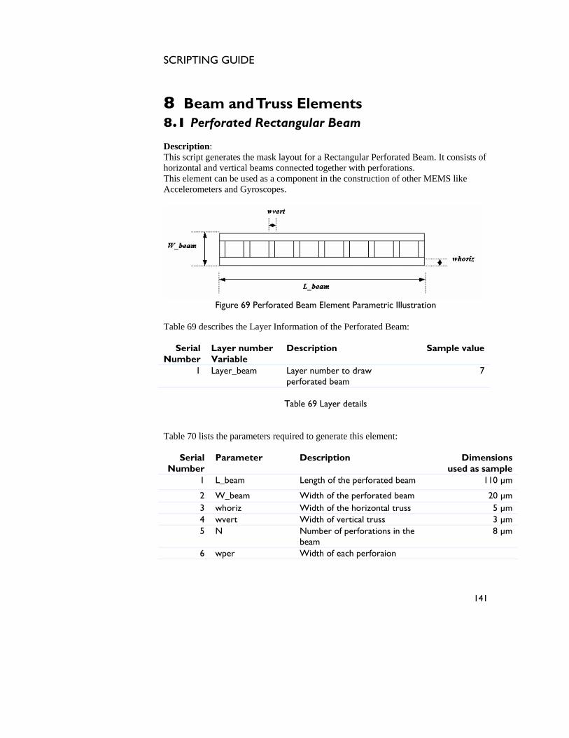
SCRIPTING GUIDE
8 Beam and Truss Elements
nerates the mask layout for a Rectangular Perforated Beam. It consists of horizontal and vertical beams connected together with perforations. This element can be used as a component in the construction of other MEMS like Accelerometers and Gyroscopes.
8.1 Perforated Rectangular Beam Description: This script ge
Figure 69 Perforated Beam Element Parametric Illustration
Table 69 describes the Layer Information of the Perforated Beam:
Serial Number
Layer number Variable
Description Sample value
1 Layer_beam Layer number to draw perforated beam
7
Table 69 Layer details
Table 70 lists
Dimensions used as sample
he perforated beam 0 µm
the parameters required to generate this element:
Serial Number
Parameter Description
1 L_beam Length of t 11
2 W_beam Width of the perforated beam 20 µm 3 whoriz ntal truss 5 µm Width of the horizo4 wvert rtical truss 3 µm Width of ve5 N Number of perforations in the 8 µm
beam 6 wper Width of each perforaion
141
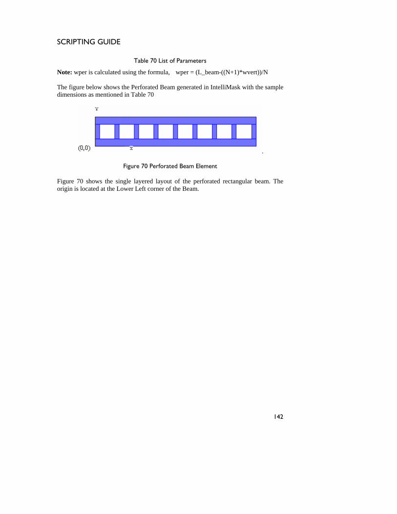
SCRIPTING GUIDE
Table 70 List of Parameters
Not is ng the fo (L_beam-((N+1)*wvert))/ T elo ows the Perforated withdimensions as ioned in Table 7
e: wper
he figure b
calculated usi rmula, wper = N
the sample w sh ment
Beam generated in IntelliMask0
.
Figure 70 P ment
Figure 70 shows the single ated rectangular beam. The located at the Lower Left corner of the Beam.
erforated Beam Ele
layered layout of the perfororigin is
142
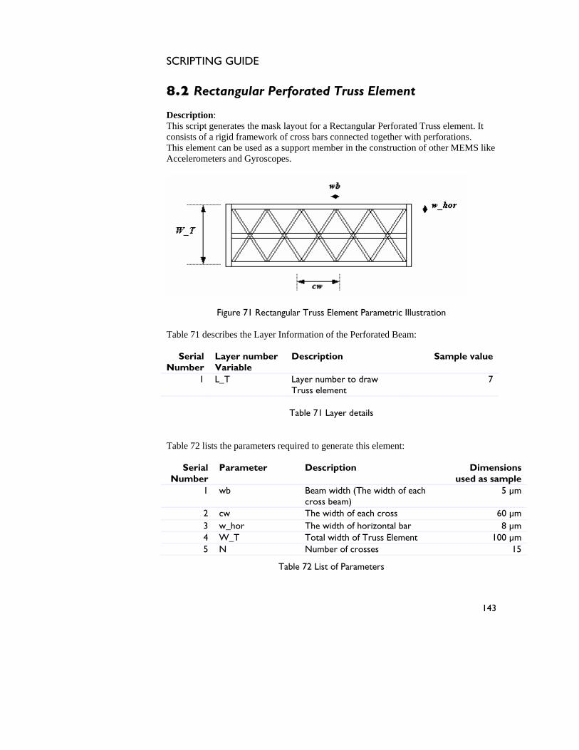
SCRIPTING GUIDE
8.2 Rectangular Perforated Truss Element Description: This script generates the mask layout for a Rectangular Perforated Truss element. It consists of a rigid framework of cross bars connected together with perforations. This element can be used as a support member in the construction of other MEMS like Accelerometers and Gyroscopes.
Figure 71 Rectangular Truss Element Parametric Illustration Table 71 describes the Layer Information of the Perforated Beam:
Serial Number
Layer number Variable
Description Sample value
1 L_T Layer number to draw Truss element
7
Table 71 Layer details
Table 72 lists the parameters required to generate this element:
Serial Number
Parameter Description Dimensions used as sample
1 wb Beam width (The width of each cross beam)
5 µm
2 cw The width of each cross 60 µm 3 w_hor The width of horizontal bar 8 µm 4 W_T Total width of Truss Element 100 µm 5 N Number of crosses 15
Table 72 List of Parameters
143
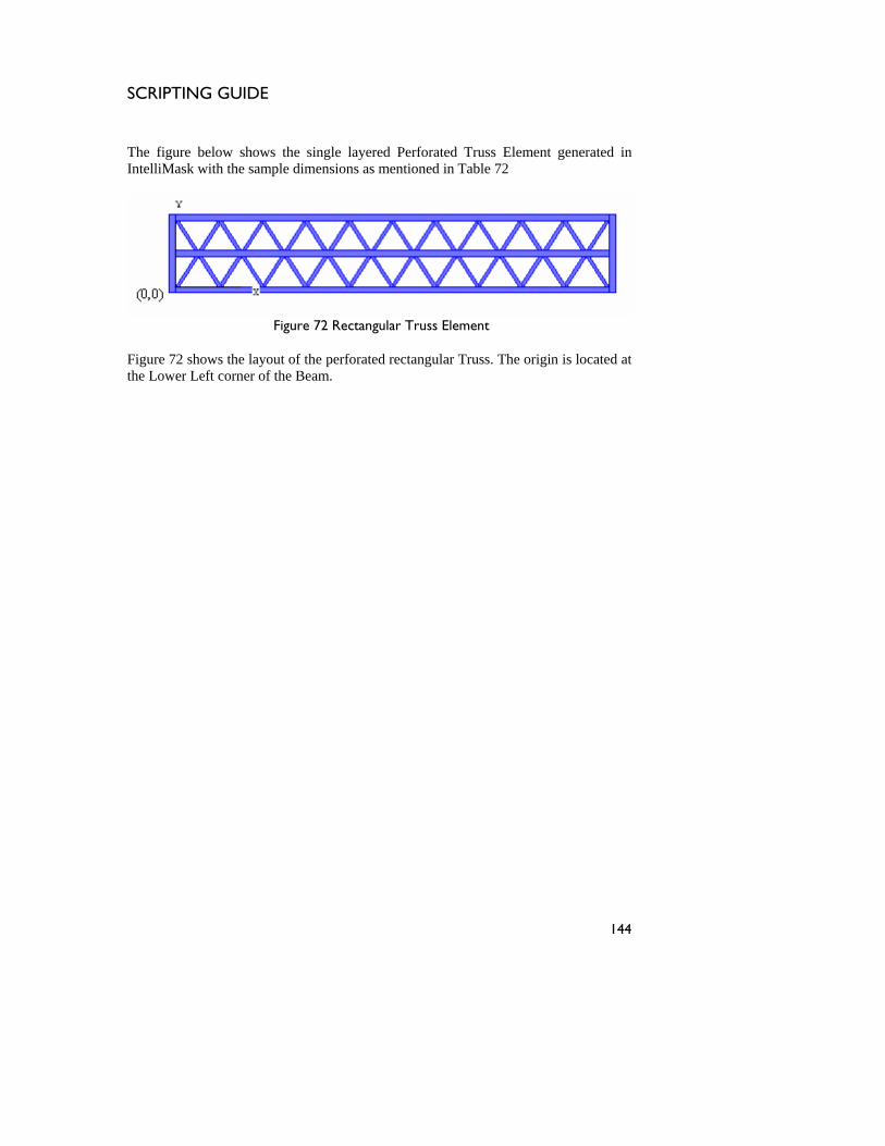
SCRIPTING GUIDE
e single layered Perforated Truss Element generated in dimensions as mentioned in Table 72
The figure below shows thIntelliMask with the sample
Figure 72 Rectangular Truss Element
Figure 72 shows the layout of the perforated rectangular Truss. The origin is located at the Lower Left corner of the Beam.
144
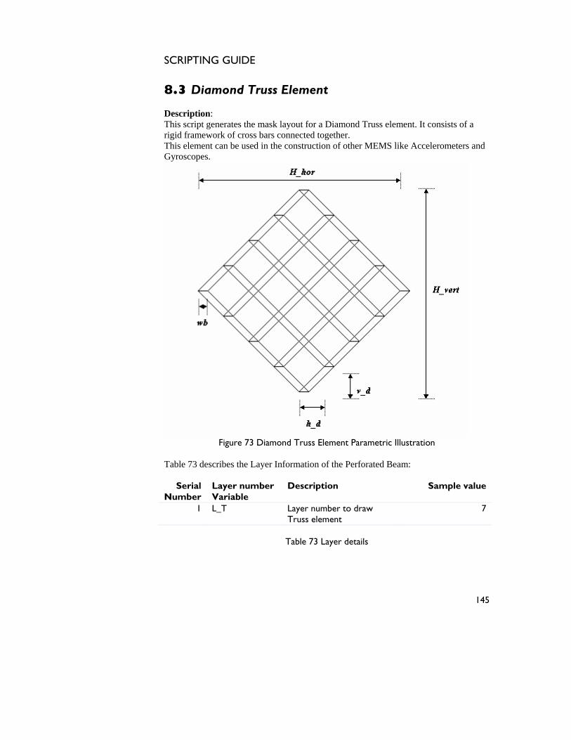
SCRIPTING GUIDE
8.3 Diamond Truss Element Description: This script generates the mask layout for a Diamond Truss element. It consists of a rigid framework of cross bars connected together. This element can be used in the construction of other MEMS like Accelerometers and Gyroscopes.
Figure 73 Diamond Truss Element Parametric Illustration
Table 73 describes the Layer Information of the Perforated Beam:
Serial Number
Layer number Variable
Description Sample value
1 L_T Layer number to draw Truss element
7
Table 73 Layer details
145
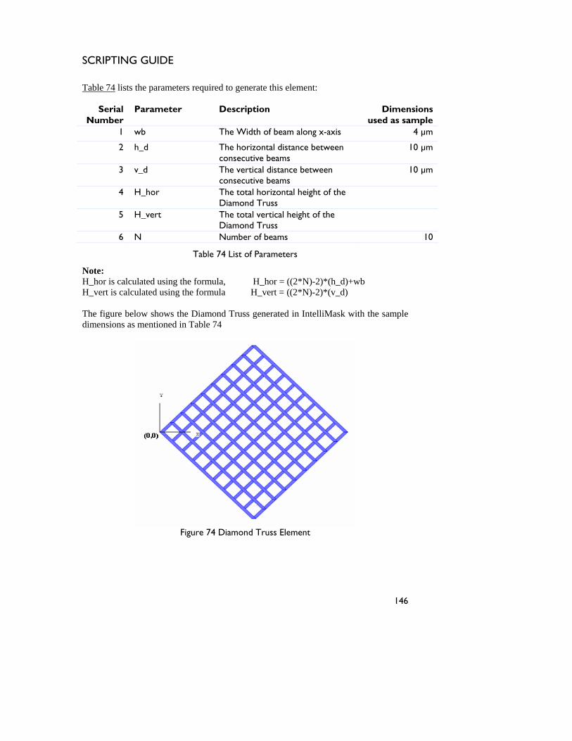
SCRIPTING GUIDE
Table 74 lists the parameters required to generate this element:
Serial Number
Parameter Description Dimensions used as sample
1 wb The Width of beam along x-axis 4 µm
2 h_d The horizontal distance between consecutive beams
10 µm
3 v_d The vertical distance between consecutive beams
10 µm
4 H_hor The total horizontal height of the Diamond Truss
5 H_vert The total vertical height of the Diamond Truss
6 N Number of beams 10
Table 74 List of Parameters
Note: H_hor is calculated using the formula, H_hor = ((2*N)-2)*(h_d)+wb H_vert is calculated using the formula H_vert = ((2*N)-2)*(v_d) The figure below shows the Diamond Truss generated in IntelliMask with the sample dimensions as mentioned in Table 74
Figure 74 Diamond Truss Element
146

SCRIPTING GUIDE
The above figure shows the layout of the Diamond Truss. The origin is located at the Left centre of the Truss Element. The element shown has 10 beams across in both the directions.
147

SCRIPTING GUIDE
148
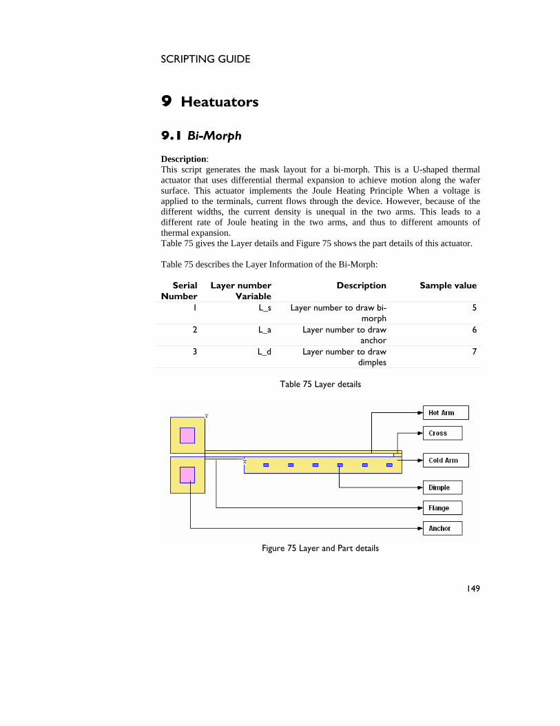
SCRIPTING GUIDE
9 Heatuators 9.1 Bi-Morph Description: This script generates the mask layout for a bi-morph. This is a U-shaped thermal actuator that uses differential thermal expansion to achieve motion along the wafer surface. This actuator implements the Joule Heating Principle When a voltage is applied to the terminals, current flows through the device. However, because of the different widths, the current density is unequal in the two arms. This leads to a different rate of Joule heating in the two arms, and thus to different amounts of thermal expansion. Table 75 gives the Layer details and Figure 75 shows the part details of this actuator. Table 75 describes the Layer Information of the Bi-Morph:
Serial Number
Layer number Variable
Description Sample value
1 L_s Layer number to draw bi-morph
5
2 L_a Layer number to draw anchor
6
3 L_d Layer number to draw dimples
7
Table 75 Layer details
Figure 75 Layer and Part details
149
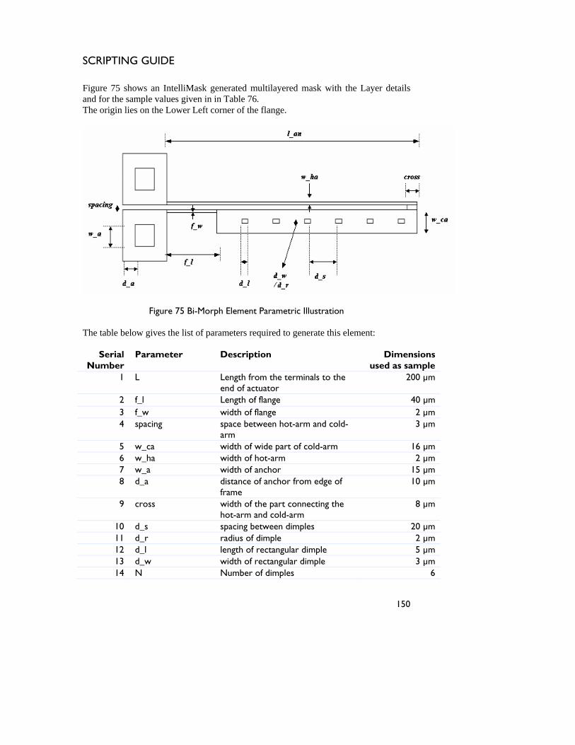
SCRIPTING GUIDE
Figure 75 shows an IntelliMask generated multilayered mask with the Layer details and for the sample values given in in Table 76. The origin lies on the Lower Left corner of the flange.
Figure 75 Bi-Morph Element Parametric Illustration
The table below gives the list of parameters required to generate this element:
Serial Number
Parameter Description Dimensions used as sample
1 L Length from the terminals to the end of actuator
200 µm
2 f_l Length of flange 40 µm 3 f_w width of flange 2 µm 4 spacing space between hot-arm and cold-
arm 3 µm
5 w_ca width of wide part of cold-arm 16 µm 6 w_ha width of hot-arm 2 µm 7 w_a width of anchor 15 µm 8 d_a distance of anchor from edge of
frame 10 µm
9 cross width of the part connecting the hot-arm and cold-arm
8 µm
10 d_s spacing between dimples 20 µm 11 d_r radius of dimple 2 µm 12 d_l length of rectangular dimple 5 µm 13 d_w width of rectangular dimple 3 µm 14 N Number of dimples 6
150

SCRIPTING GUIDE
15 dimple_type type of dimple, Round or Rectangle
1 µm
Table 76 List of parameters
Note: For round dimple enter dimple_type = 0 For rectangular dimple enter dimple_type = 1
151
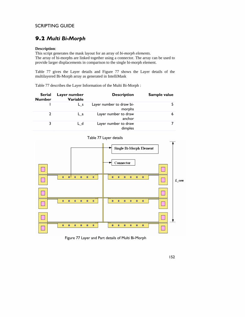
SCRIPTING GUIDE
9.2 Multi Bi-Morph Description: This script generates the mask layout for an array of bi-morph elements. The array of bi-morphs are linked together using a connector. The array can be used to provide larger displacements in comparison to the single bi-morph element. Table 77 gives the Layer details and Figure 77 shows the Layer details of the multilayered Bi-Morph array as generated in IntelliMask Table 77 describes the Layer Information of the Multi Bi-Morph :
Serial Number
Layer number Variable
Description Sample value
1 L_s Layer number to draw bi-morphs
5
2 L_a Layer number to draw anchor
6
3 L_d Layer number to draw dimples
7
Table 77 Layer details
Figure 77 Layer and Part details of Multi Bi-Morph
152
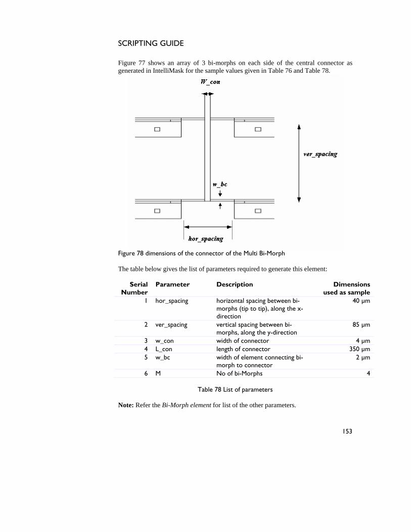
SCRIPTING GUIDE
Figure 77 shows an array of 3 bi-morphs on each side of the central connector as generated in IntelliMask for the sample values given in Table 76 and Table 78.
Figure 78 dimensions of the connector of the Multi Bi-Morph The table below gives the list of parameters required to generate this element:
Serial Number
Parameter Description Dimensions used as sample
1 hor_spacing horizontal spacing between bi-morphs (tip to tip), along the x-direction
40 µm
2 ver_spacing vertical spacing between bi-morphs, along the y-direction
85 µm
3 w_con width of connector 4 µm 4 L_con length of connector 350 µm 5 w_bc width of element connecting bi-
morph to connector 2 µm
6 M No of bi-Morphs 4
Table 78 List of parameters Note: Refer the Bi-Morph element for list of the other parameters.
153
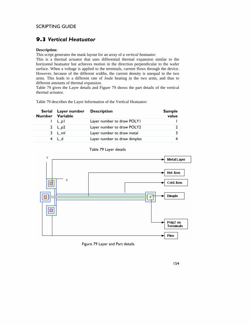
SCRIPTING GUIDE
9.3 Vertical Heatuator Description: This script generates the mask layout for an array of a vertical heatuator. This is a thermal actuator that uses differential thermal expansion similar to the horizontal heatuator but achieves motion in the direction perpendicular to the wafer surface. When a voltage is applied to the terminals, current flows through the device. However, because of the different widths, the current density is unequal in the two arms. This leads to a different rate of Joule heating in the two arms, and thus to different amounts of thermal expansion. Table 79 gives the Layer details and Figure 79 shows the part details of the vertical thermal actuator. Table 79 describes the Layer Information of the Vertical Heatuator:
Serial Number
Layer number Variable
Description Sample value
1 L_p1 Layer number to draw POLY1 1
2 L_p2 Layer number to draw POLY2 2 3 L_ml Layer number to draw metal 3 4 L_d Layer number to draw dimples 4
Table 79 Layer details
Figure 79 Layer and Part details
154
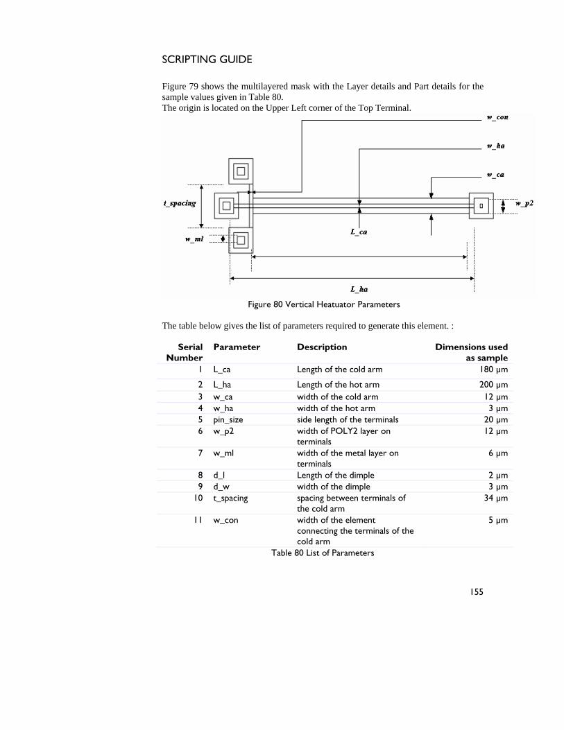
SCRIPTING GUIDE
Figure 79 shows the multilayered mask with the Layer details and Part details for the sample values given in Table 80. The origin is located on the Upper Left corner of the Top Terminal.
Figure 80 Vertical Heatuator Parameters The table below gives the list of parameters required to generate this element. :
Serial Number
Parameter Description Dimensions used as sample
1 L_ca Length of the cold arm 180 µm
2 L_ha Length of the hot arm 200 µm 3 w_ca width of the cold arm 12 µm 4 w_ha width of the hot arm 3 µm 5 pin_size side length of the terminals 20 µm 6 w_p2 width of POLY2 layer on
terminals 12 µm
7 w_ml width of the metal layer on terminals
6 µm
8 d_l Length of the dimple 2 µm 9 d_w width of the dimple 3 µm
10 t_spacing spacing between terminals of the cold arm
34 µm
11 w_con width of the element connecting the terminals of the cold arm
5 µm
Table 80 List of Parameters
155
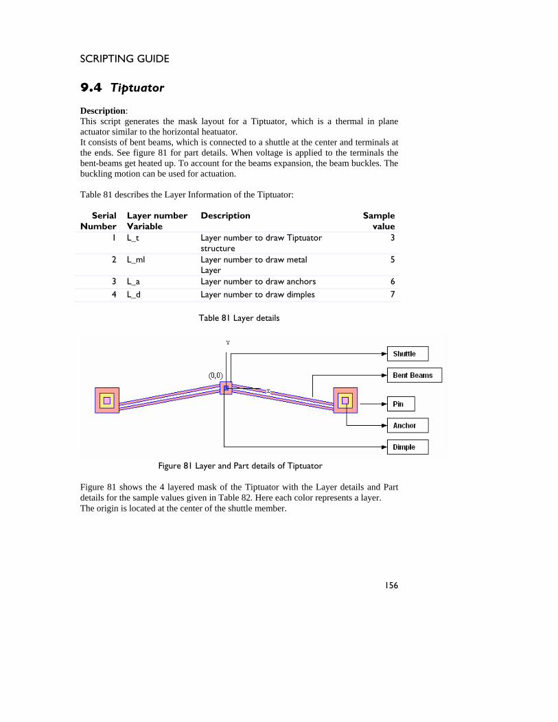
SCRIPTING GUIDE
9.4 Tiptuator Description: This script generates the mask layout for a Tiptuator, which is a thermal in plane actuator similar to the horizontal heatuator. It consists of bent beams, which is connected to a shuttle at the center and terminals at the ends. See figure 81 for part details. When voltage is applied to the terminals the bent-beams get heated up. To account for the beams expansion, the beam buckles. The buckling motion can be used for actuation. Table 81 describes the Layer Information of the Tiptuator:
Serial Number
Layer number Variable
Description Sample value
1 L_t Layer number to draw Tiptuator structure
3
2 L_ml Layer number to draw metal Layer
5
3 L_a Layer number to draw anchors 6 4 L_d Layer number to draw dimples 7
Table 81 Layer details
Figure 81 Layer and Part details of Tiptuator
Figure 81 shows the 4 layered mask of the Tiptuator with the Layer details and Part details for the sample values given in Table 82. Here each color represents a layer. The origin is located at the center of the shuttle member.
156
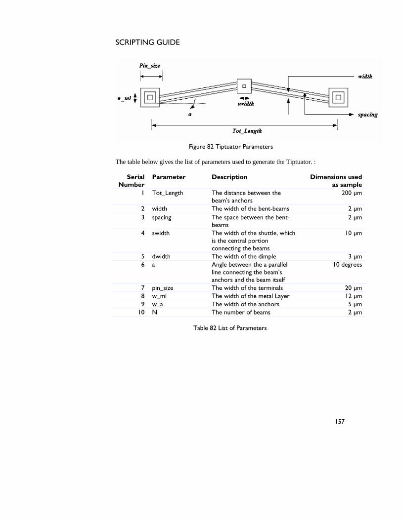
SCRIPTING GUIDE
Figure 82 Tiptuator Parameters The table below gives the list of parameters used to generate the Tiptuator. :
Serial Number
Parameter Description Dimensions used as sample
1 Tot_Length The distance between the beam's anchors
200 µm
2 width The width of the bent-beams 2 µm 3 spacing The space between the bent-
beams 2 µm
4 swidth The width of the shuttle, which is the central portion connecting the beams
10 µm
5 dwidth The width of the dimple 3 µm 6 a Angle between the a parallel
line connecting the beam's anchors and the beam itself
10 degrees
7 pin_size The width of the terminals 20 µm 8 w_ml The width of the metal Layer 12 µm 9 w_a The width of the anchors 5 µm
10 N The number of beams 2 µm
Table 82 List of Parameters
157

SCRIPTING GUIDE
158
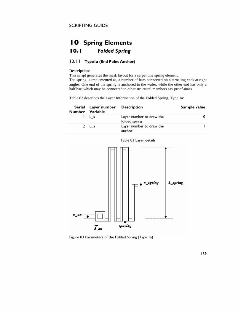
SCRIPTING GUIDE
10 Spring Elements 10.1 Folded Spring 10.1.1 Type1a (End Point Anchor) Description: This script generates the mask layout for a serpentine spring element. The spring is implemented as, a number of bars connected on alternating ends at right angles. One end of the spring is anchored to the wafer, while the other end has only a half bar, which may be connected to other structural members say proof-mass. Table 83 describes the Layer Information of the Folded Spring, Type 1a:
Serial Number
Layer number Variable
Description Sample value
1 L_s Layer number to draw the folded spring
0
2 L_a Layer number to draw the anchor
1
Table 83 Layer details
Figure 83 Parameters of the Folded Spring (Type 1a)
159
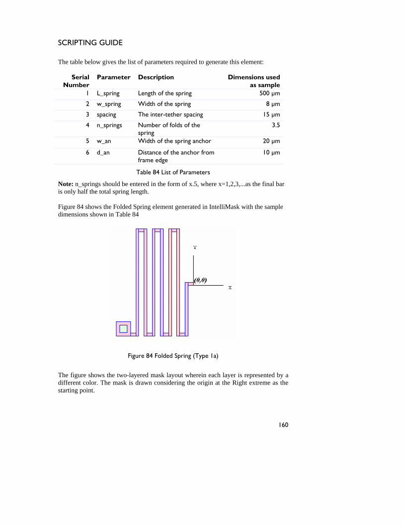
SCRIPTING GUIDE
The table below gives the list of parameters required to generate this element:
Serial Number
Parameter Description Dimensions used as sample
1 L_spring Length of the spring 500 µm
2 w_spring Width of the spring 8 µm
3 spacing The inter-tether spacing 15 µm
4 n_springs Number of folds of the spring
3.5
5 w_an Width of the spring anchor 20 µm
6 d_an Distance of the anchor from frame edge
10 µm
Table 84 List of Parameters
Note: n_springs should be entered in the form of x.5, where x=1,2,3,...as the final bar is only half the total spring length. Figure 84 shows the Folded Spring element generated in IntelliMask with the sample dimensions shown in Table 84
Figure 84 Folded Spring (Type 1a)
The figure shows the two-layered mask layout wherein each layer is represented by a different color. The mask is drawn considering the origin at the Right extreme as the starting point.
160
SCRIPTING GUIDE
10.1.2 Type1b (End Point Anchor) Description: This script generates the mask layout for a serpentine spring element. The spring is implemented as, a number of bars connected on alternating ends at right angles. One end of the spring is anchored to the wafer, while the other end may be connected to other structural members say proof-mass. This spring is different from Type 1a in the fact that the length and width of this spring are orthogonal that of type 1a as evident from figure 84a. The Layer Information is same as spring type 1a described in Table 83. The table below gives the list of parameters required to generate this element:
Serial Number
Parameter Description Dimensions used as sample
1 L_spring Length of the spring 500 µm
2 w_spring Width of the spring 8 µm
3 spacing The inter-tether spacing 15 µm
4 n_springs Number of folds of the spring
3
5 w_an Width of the spring anchor 20 µm
6 d_an Distance of the anchor from frame edge
10 µm
Table 84a List of Parameters
Figure 84a shows the Folded Spring element generated in IntelliMask with the sample dimensions shown in Table 84
161
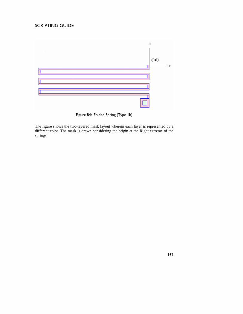
SCRIPTING GUIDE
Figure 84a Folded Spring (Type 1b)
The figure shows the two-layered mask layout wherein each layer is represented by a different color. The mask is drawn considering the origin at the Right extreme of the springs.
162
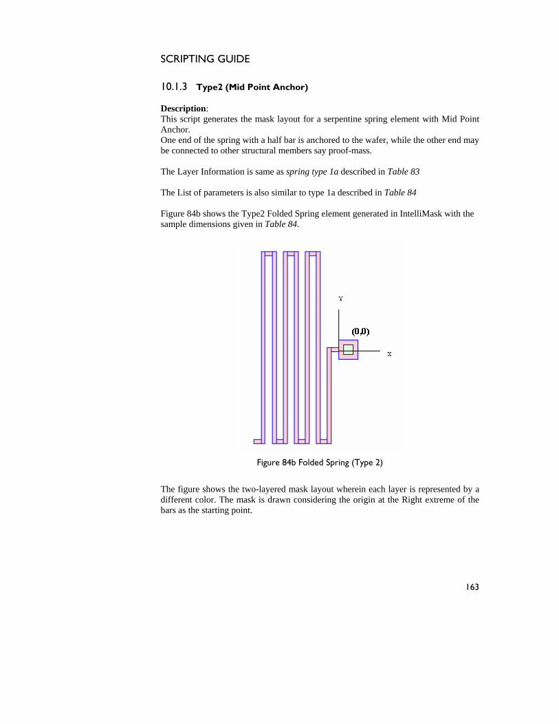
SCRIPTING GUIDE
10.1.3 Type2 (Mid Point Anchor) Description: This script generates the mask layout for a serpentine spring element with Mid Point Anchor. One end of the spring with a half bar is anchored to the wafer, while the other end may be connected to other structural members say proof-mass. The Layer Information is same as spring type 1a described in Table 83 The List of parameters is also similar to type 1a described in Table 84 Figure 84b shows the Type2 Folded Spring element generated in IntelliMask with the sample dimensions given in Table 84.
Figure 84b Folded Spring (Type 2)
The figure shows the two-layered mask layout wherein each layer is represented by a different color. The mask is drawn considering the origin at the Right extreme of the bars as the starting point.
163
SCRIPTING GUIDE
10.1.4 Double Anchored Spring Description: This script generates the mask layout for a double anchored serpentine spring element. The spring is implemented as, a number of bars connected on alternating ends at right angles. The two ends of the spring is anchored to the wafer. There is a central prong dividing the spring into symmetrical halves. This is a Mid Point anchor type spring. The Layer Information is same as spring type 1a described in Table 83. The table below gives the list of parameters and values required to generate this element:
Serial Number
Parameter Description Dimensions used as sample
1 L_spring Length of the spring 400 µm
2 w_spring Width of the spring 8 µm
3 spacing The inter-tether spacing 20 µm
4 n_springs Number of folds of the spring
2.5
5 w_an Width of the spring anchor 20 µm
6 d_an Distance of the anchor from frame edge
10 µm
7 L_prong Length of the central prong 500 8 w_prong width of central prong 10 µm
Table 84c List of Parameters
Note: n_springs should be entered in the form of x.5, where x=1,2,3,...as the final bar is only half the total spring length. Figure 84c shows the Folded Spring element generated in IntelliMask with the sample dimensions given in Table 84c. The figure also depicts the parameters used to draw the central prong.
164
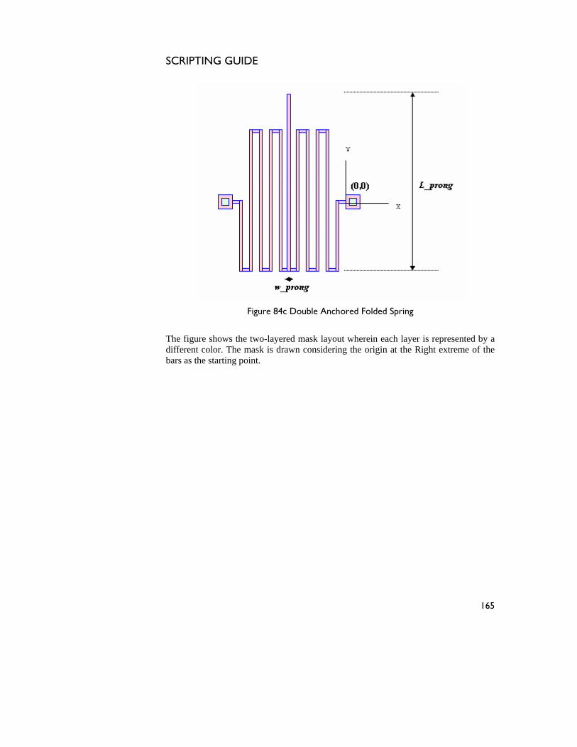
SCRIPTING GUIDE
Figure 84c Double Anchored Folded Spring
The figure shows the two-layered mask layout wherein each layer is represented by a different color. The mask is drawn considering the origin at the Right extreme of the bars as the starting point.
165
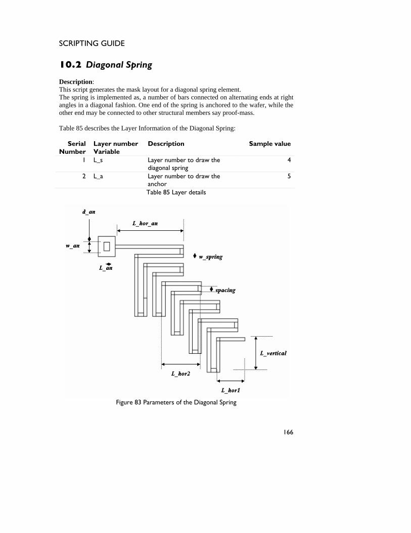
SCRIPTING GUIDE
10.2 Diagonal Spring Description: This script generates the mask layout for a diagonal spring element. The spring is implemented as, a number of bars connected on alternating ends at right angles in a diagonal fashion. One end of the spring is anchored to the wafer, while the other end may be connected to other structural members say proof-mass. Table 85 describes the Layer Information of the Diagonal Spring:
Serial Number
Layer number Variable
Description Sample value
1 L_s Layer number to draw the diagonal spring
4
2 L_a Layer number to draw the anchor
5
Table 85 Layer details
Figure 83 Parameters of the Diagonal Spring
166
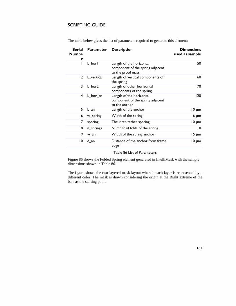
SCRIPTING GUIDE
The table below gives the list of parameters required to generate this element:
Serial Numbe
r
Parameter Description Dimensions used as sample
1 L_hor1 Length of the horizontal component of the spring adjacent to the proof mass
50
2 L_vertical Length of vertical components of the spring
60
3 L_hor2 Length of other horizontal components of the spring
70
4 L_hor_an Length of the horizontal component of the spring adjacent to the anchor
120
5 L_an Length of the anchor 10 µm
6 w_spring Width of the spring 6 µm
7 spacing The inter-tether spacing 10 µm
8 n_springs Number of folds of the spring 10
9 w_an Width of the spring anchor 15 µm
10 d_an Distance of the anchor from frame edge
10 µm
Table 86 List of Parameters
Figure 86 shows the Folded Spring element generated in IntelliMask with the sample dimensions shown in Table 86. The figure shows the two-layered mask layout wherein each layer is represented by a different color. The mask is drawn considering the origin at the Right extreme of the bars as the starting point.
167
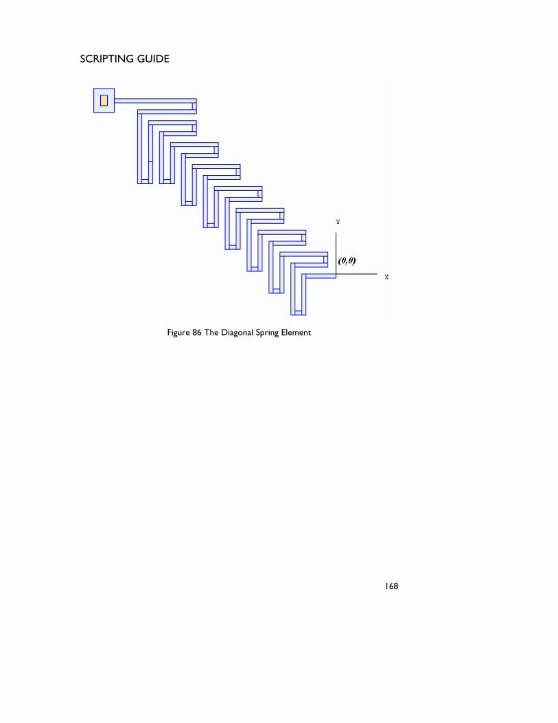
SCRIPTING GUIDE
Figure 86 The Diagonal Spring Element
168
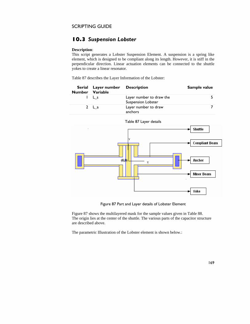
SCRIPTING GUIDE
10.3 Suspension Lobster Description: This script generates a Lobster Suspension Element. A suspension is a spring like element, which is designed to be compliant along its length. However, it is stiff in the perpendicular direction. Linear actuation elements can be connected to the shuttle yokes to create a linear resonator. Table 87 describes the Layer Information of the Lobster:
Serial Number
Layer number Variable
Description Sample value
1 L_s Layer number to draw the Suspension Lobster
5
2 L_a Layer number to draw anchors
7
Table 87 Layer details
Figure 87 Part and Layer details of Lobster Element
Figure 87 shows the multilayered mask for the sample values given in Table 88. The origin lies at the center of the shuttle. The various parts of the capacitor structure are described above. The parametric Illustration of the Lobster element is shown below.:
169
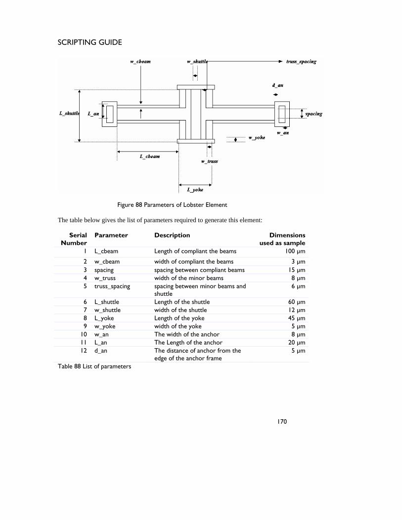
SCRIPTING GUIDE
Figure 88 Parameters of Lobster Element
The table below gives the list of parameters required to generate this element:
Serial Number
Parameter Description Dimensions used as sample
1 L_cbeam Length of compliant the beams 100 µm
2 w_cbeam width of compliant the beams 3 µm 3 spacing spacing between compliant beams 15 µm 4 w_truss width of the minor beams 8 µm 5 truss_spacing spacing between minor beams and
shuttle 6 µm
6 L_shuttle Length of the shuttle 60 µm 7 w_shuttle width of the shuttle 12 µm 8 L_yoke Length of the yoke 45 µm 9 w_yoke width of the yoke 5 µm
10 w_an The width of the anchor 8 µm 11 L_an The Length of the anchor 20 µm 12 d_an The distance of anchor from the
edge of the anchor frame 5 µm
Table 88 List of parameters
170
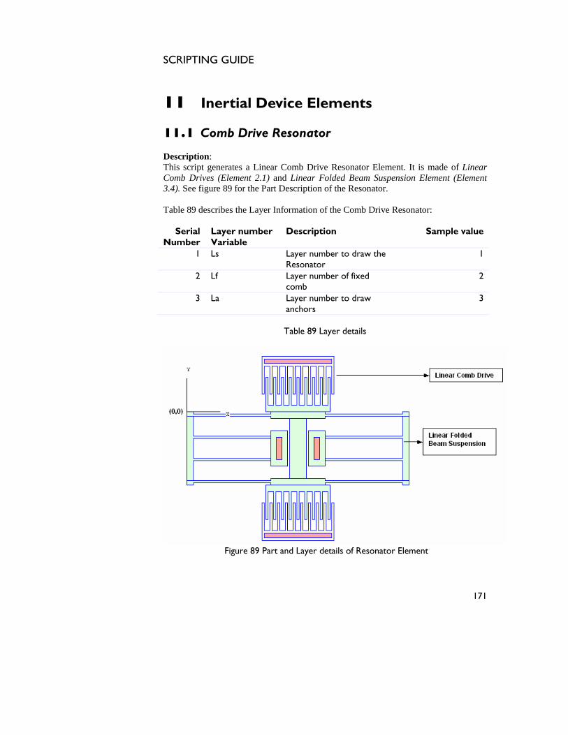
SCRIPTING GUIDE
11 Inertial Device Elements 11.1 Comb Drive Resonator Description: This script generates a Linear Comb Drive Resonator Element. It is made of Linear Comb Drives (Element 2.1) and Linear Folded Beam Suspension Element (Element 3.4). See figure 89 for the Part Description of the Resonator. Table 89 describes the Layer Information of the Comb Drive Resonator:
Serial Number
Layer number Variable
Description Sample value
1 Ls Layer number to draw the Resonator
1
2 Lf Layer number of fixed comb
2
3 La Layer number to draw anchors
3
Table 89 Layer details
Figure 89 Part and Layer details of Resonator Element
171
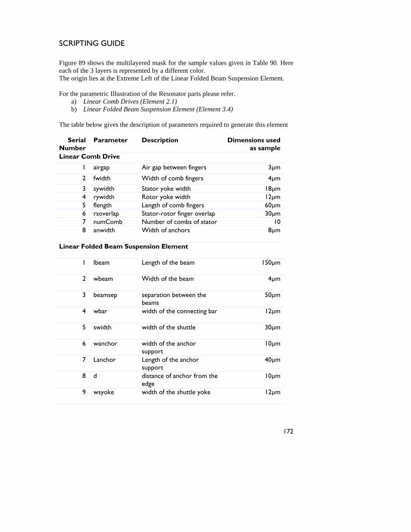
SCRIPTING GUIDE
Figure 89 shows the multilayered mask for the sample values given in Table 90. Here each of the 3 layers is represented by a different color. The origin lies at the Extreme Left of the Linear Folded Beam Suspension Element. For the parametric Illustration of the Resonator parts please refer.
a) Linear Comb Drives (Element 2.1) b) Linear Folded Beam Suspension Element (Element 3.4)
The table below gives the description of parameters required to generate this element
Serial Number
Parameter Description Dimensions used as sample
Linear Comb Drive
1 airgap Air gap between fingers 3µm
2 fwidth Width of comb fingers 4µm
3 sywidth Stator yoke width 18µm 4 rywidth Rotor yoke width 12µm 5 flength Length of comb fingers 60µm 6 rsoverlap Stator-rotor finger overlap 30µm 7 numComb Number of combs of stator 10 8 anwidth Width of anchors 8µm
Linear Folded Beam Suspension Element
1 lbeam Length of the beam 150µm
2 wbeam Width of the beam 4µm
3 beamsep separation between the beams
50µm
4 wbar width of the connecting bar 12µm
5 swidth width of the shuttle 30µm
6 wanchor width of the anchor support
10µm
7 Lanchor Length of the anchor support
40µm
8 d distance of anchor from the edge
10µm
9 wsyoke width of the shuttle yoke 12µm
172

SCRIPTING GUIDE
10 lsyoke Length of the shuttle yoke 98µm
Table 89 List of parameters
173
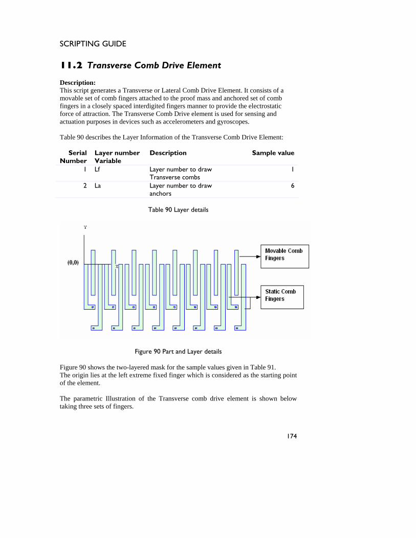
SCRIPTING GUIDE
11.2 Transverse Comb Drive Element Description: This script generates a Transverse or Lateral Comb Drive Element. It consists of a movable set of comb fingers attached to the proof mass and anchored set of comb fingers in a closely spaced interdigited fingers manner to provide the electrostatic force of attraction. The Transverse Comb Drive element is used for sensing and actuation purposes in devices such as accelerometers and gyroscopes. Table 90 describes the Layer Information of the Transverse Comb Drive Element:
Serial Number
Layer number Variable
Description Sample value
1 Lf Layer number to draw Transverse combs
1
2 La Layer number to draw anchors
6
Table 90 Layer details
Figure 90 Part and Layer details
Figure 90 shows the two-layered mask for the sample values given in Table 91. The origin lies at the left extreme fixed finger which is considered as the starting point of the element. The parametric Illustration of the Transverse comb drive element is shown below taking three sets of fingers.
174
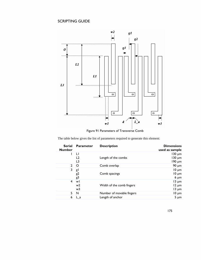
SCRIPTING GUIDE
Figure 91 Parameters of Transverse Comb
The table below gives the list of parameters required to generate this element:
Serial Number
Parameter Description Dimensions used as sample
1 L1 L2 L3
Length of the combs
130 µm 130 µm 190 µm
2 O Comb overlap 90 µm 3 g1
g2 g3
Comb spacings
10 µm 10 µm 6 µm
4 w1 w2 w3
Width of the comb fingers
13 µm 12 µm 13 µm
5 N Number of movable fingers 10 µm 6 L_a Length of anchor 5 µm
175

SCRIPTING GUIDE
7 W_a Width of anchor 3 µm 8 R Radius of curvature of anchor 0 µm 9 d Distance of anchor from the edge 5 µm
Table 91 List of parameters of Transverse Comb
176
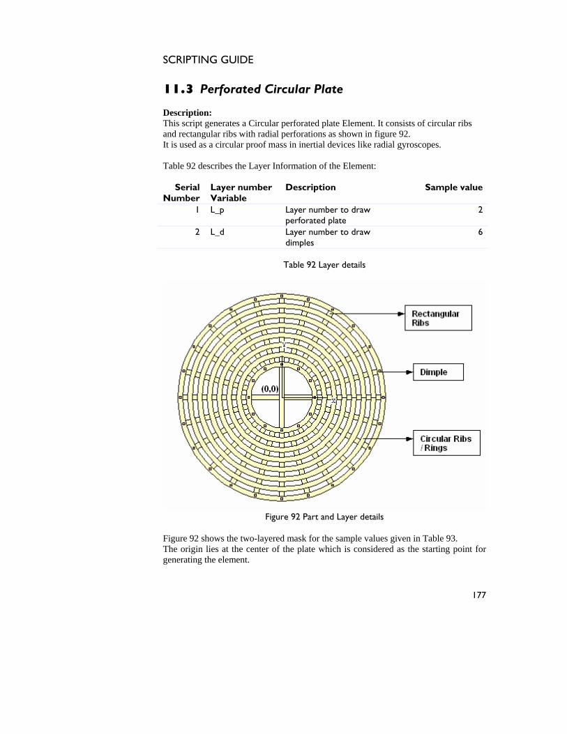
SCRIPTING GUIDE
11.3 Perforated Circular Plate Description: This script generates a Circular perforated plate Element. It consists of circular ribs and rectangular ribs with radial perforations as shown in figure 92. It is used as a circular proof mass in inertial devices like radial gyroscopes. Table 92 describes the Layer Information of the Element:
Serial Number
Layer number Variable
Description Sample value
1 L_p Layer number to draw perforated plate
2
2 L_d Layer number to draw dimples
6
Table 92 Layer details
Figure 92 Part and Layer details
Figure 92 shows the two-layered mask for the sample values given in Table 93. The origin lies at the center of the plate which is considered as the starting point for generating the element.
177
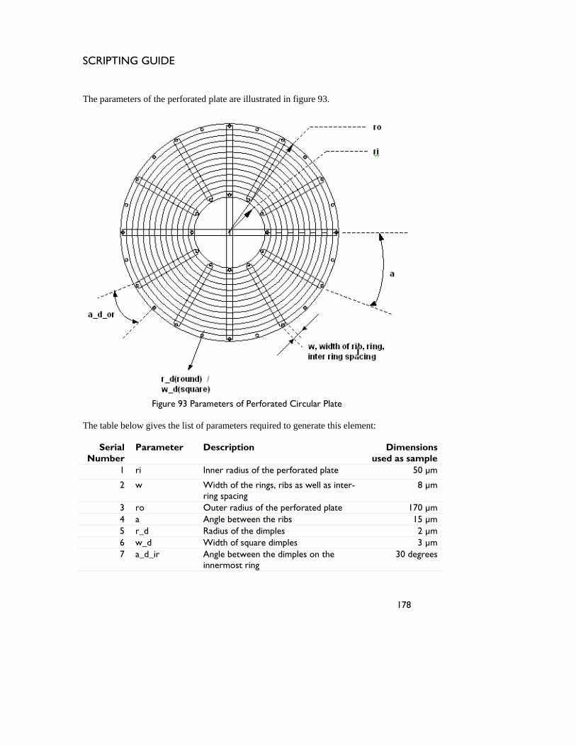
SCRIPTING GUIDE
The parameters of the perforated plate are illustrated in figure 93.
Figure 93 Parameters of Perforated Circular Plate
The table below gives the list of parameters required to generate this element:
Serial Number
Parameter Description Dimensions used as sample
1 ri Inner radius of the perforated plate 50 µm
2 w Width of the rings, ribs as well as inter-ring spacing
8 µm
3 ro Outer radius of the perforated plate 170 µm 4 a Angle between the ribs 15 µm 5 r_d Radius of the dimples 2 µm 6 w_d Width of square dimples 3 µm 7 a_d_ir Angle between the dimples on the
innermost ring 30 degrees
178
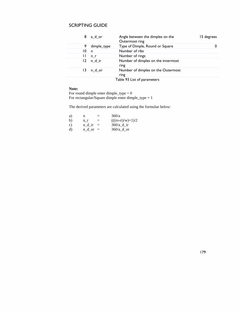
SCRIPTING GUIDE
8 a_d_or Angle between the dimples on the Outermost ring
15 degrees
9 dimple_type Type of Dimple, Round or Square 0 10 n Number of ribs 11 n_r Number of rings 12 n_d_ir Number of dimples on the innermost
ring
13 n_d_or Number of dimples on the Outermost ring
Table 93 List of parameters
Note: For round dimple enter dimple_type = 0 For rectangular/Square dimple enter dimple_type = 1 The derived parameters are calculated using the formulae below: a) n = 360/a b) n_r = (((ro-ri)/w)+1)/2 c) n_d_ir = 360/a_d_ir d) n_d_or = 360/a_d_or
179
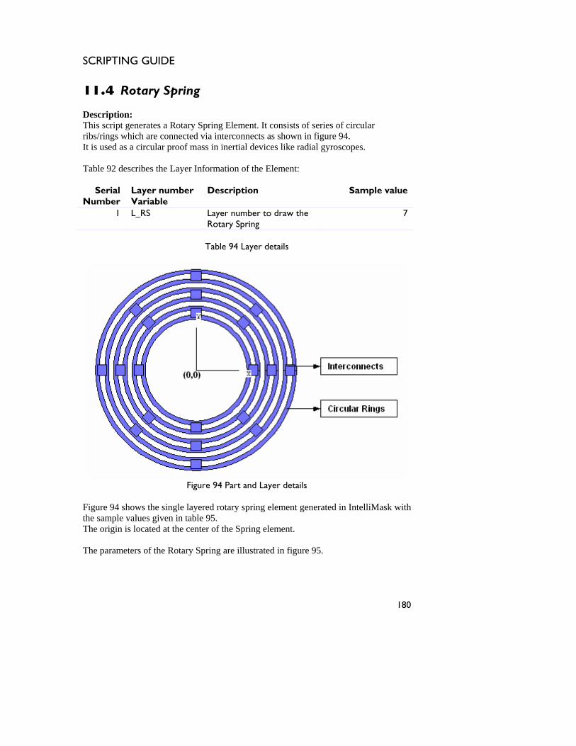
SCRIPTING GUIDE
11.4 Rotary Spring Description: This script generates a Rotary Spring Element. It consists of series of circular ribs/rings which are connected via interconnects as shown in figure 94. It is used as a circular proof mass in inertial devices like radial gyroscopes. Table 92 describes the Layer Information of the Element:
Serial Number
Layer number Variable
Description Sample value
1 L_RS Layer number to draw the Rotary Spring
7
Table 94 Layer details
Figure 94 Part and Layer details
Figure 94 shows the single layered rotary spring element generated in IntelliMask with the sample values given in table 95. The origin is located at the center of the Spring element. The parameters of the Rotary Spring are illustrated in figure 95.
180
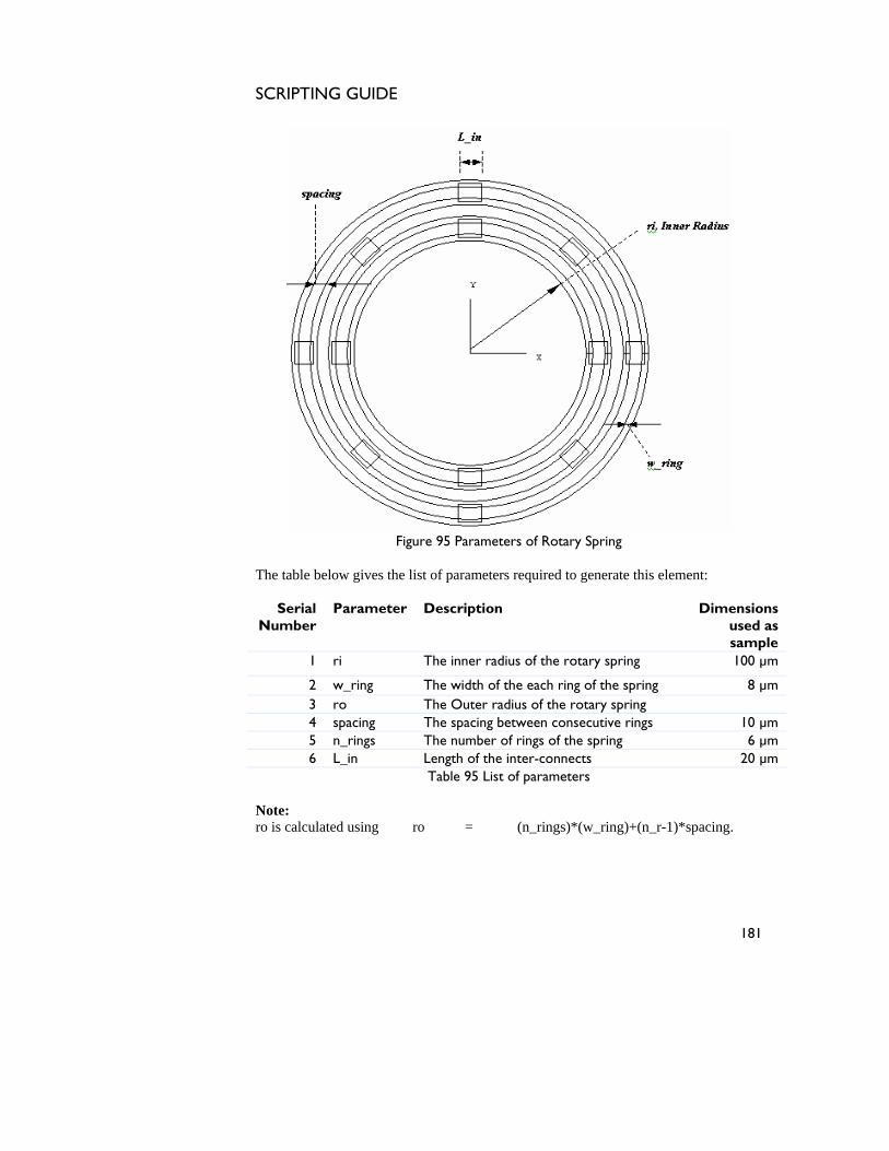
SCRIPTING GUIDE
Figure 95 Parameters of Rotary Spring
The table below gives the list of parameters required to generate this element:
Serial Number
Parameter Description Dimensions used as sample
1 ri The inner radius of the rotary spring 100 µm
2 w_ring The width of the each ring of the spring 8 µm 3 ro The Outer radius of the rotary spring 4 spacing The spacing between consecutive rings 10 µm 5 n_rings The number of rings of the spring 6 µm 6 L_in Length of the inter-connects 20 µm
Table 95 List of parameters
Note: ro is calculated using ro = (n_rings)*(w_ring)+(n_r-1)*spacing.
181
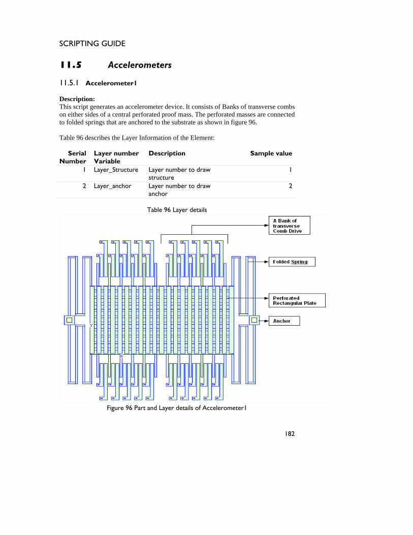
SCRIPTING GUIDE
11.5 Accelerometers 11.5.1 Accelerometer1 Description: This script generates an accelerometer device. It consists of Banks of transverse combs on either sides of a central perforated proof mass. The perforated masses are connected to folded springs that are anchored to the substrate as shown in figure 96. Table 96 describes the Layer Information of the Element:
Serial Number
Layer number Variable
Description Sample value
1 Layer_Structure Layer number to draw structure
1
2 Layer_anchor Layer number to draw anchor
2
Table 96 Layer details
Figure 96 Part and Layer details of Accelerometer1
182
SCRIPTING GUIDE
Figure 96 shows the multilayered mask for the sample values given in Table 97 as generated in IntelliMask. The origin lies at the Lower Left corner of the Perforated Plate Element. For the parametric Illustration of the parts of the Accelerometer please refer.
a) Perforated Rectangular Plate (Element 4.6) b) Folded Spring Elements (Element 10.1) c) Transverse Comb Drive (Element 11.2)
The table below gives parameters and sample values used to generate this element
Serial Number
Parameter Description Dimensions used as sample
Perforated Rectangular Plate
1 Plate_width Width of the plate 1320 µm
2 Plate_height Height of the plate 460 µm
3 Corner_radius Radius of curvature of plate 2 µm 4 n_rows Number of perforations in a
row 30
5 n_columns Number of perforations in a column
10
6 hole_width Width of the perforation 10 µm 7 hole_height Height of the perforation 10 µm
Folded Spring Element
1 L_spring Total Length of the spring 260 µm
2 w_spring Width of the beam 8 µm
3 n_folds Number of folds of the spring 2
4 spacing The inter-tether spacing 20 µm
5 w_an width of spring the anchor 20 µm
6 d_an width of the anchor support 10 µm
Transverse Comb Drive Element
1 L1 Length of the combs 100 µm
183
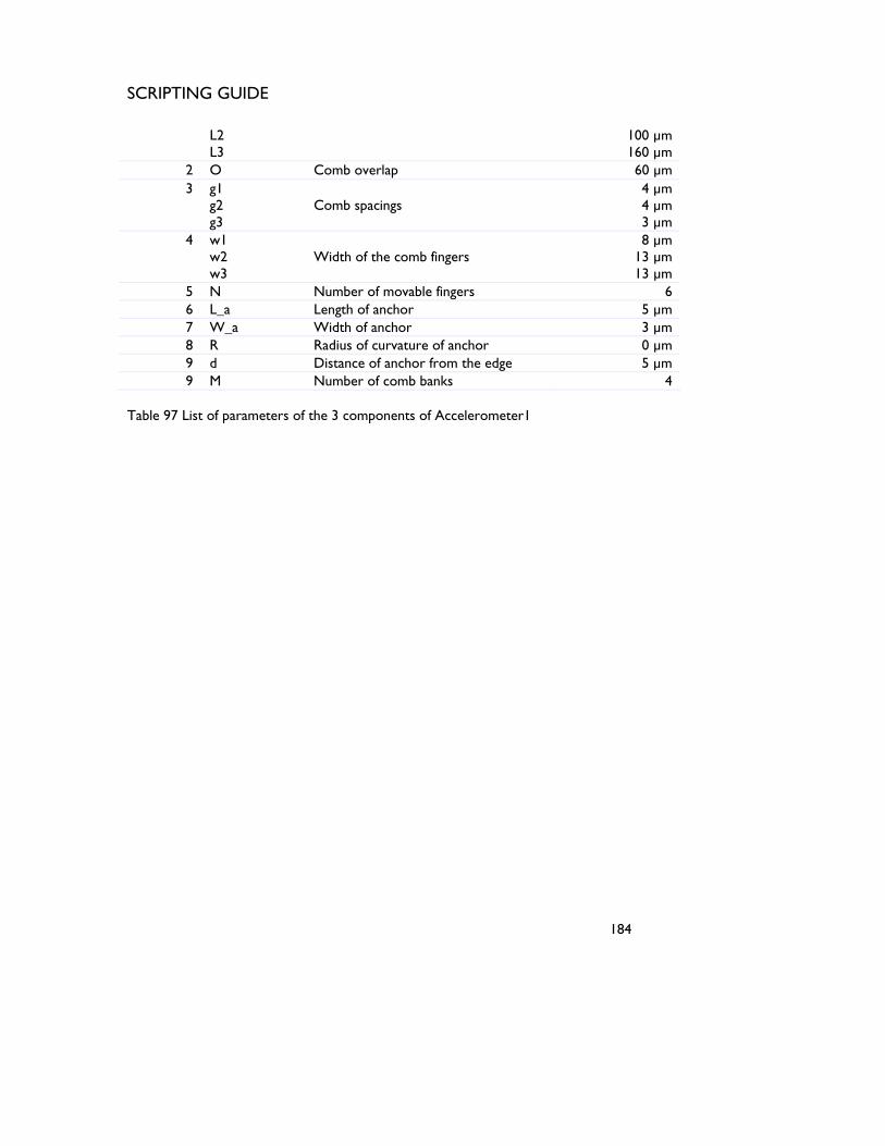
SCRIPTING GUIDE
L2 L3
100 µm 160 µm
2 O Comb overlap 60 µm 3 g1
g2 g3
Comb spacings
4 µm 4 µm 3 µm
4 w1 w2 w3
Width of the comb fingers
8 µm 13 µm 13 µm
5 N Number of movable fingers 6 6 L_a Length of anchor 5 µm 7 W_a Width of anchor 3 µm 8 R Radius of curvature of anchor 0 µm 9 d Distance of anchor from the edge 5 µm 9 M Number of comb banks 4
Table 97 List of parameters of the 3 components of Accelerometer1
184
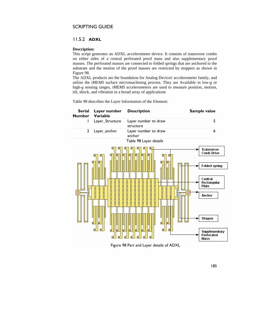
SCRIPTING GUIDE
11.5.2 ADXL Description: This script generates an ADXL accelerometer device. It consists of transverse combs on either sides of a central perforated proof mass and also supplementary proof masses. The perforated masses are connected to folded springs that are anchored to the substrate and the motion of the proof masses are restricted by stoppers as shown in Figure 98. The ADXL products are the foundation for Analog Devices' accelerometer family, and utilize the iMEMS surface micromachining process. They are Available in low-g or high-g sensing ranges, iMEMS accelerometers are used to measure position, motion, tilt, shock, and vibration in a broad array of applications Table 98 describes the Layer Information of the Element:
Serial Number
Layer number Variable
Description Sample value
1 Layer_Structure Layer number to draw structure
5
2 Layer_anchor Layer number to draw anchor
6
Table 98 Layer details
Figure 98 Part and Layer details of ADXL
185
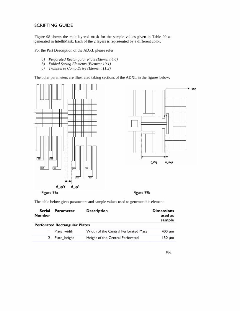
SCRIPTING GUIDE
Figure 98 shows the multilayered mask for the sample values given in Table 99 as generated in IntelliMask. Each of the 2 layers is represented by a different color. For the Part Description of the ADXL please refer.
a) Perforated Rectangular Plate (Element 4.6) b) Folded Spring Elements (Element 10.1) c) Transverse Comb Drive (Element 11.2)
The other parameters are illustrated taking sections of the ADXL in the figures below:
Figure 99a The table below gives parameters and sample values use
Serial Number
Parameter Description
Perforated Rectangular Plates
1 Plate_width Width of the Central P
2 Plate_height Height of the Central P
186
Figure 99b
d to generate this element
Dimensions used as sample
erforated Mass 400 µm
erforated 150 µm
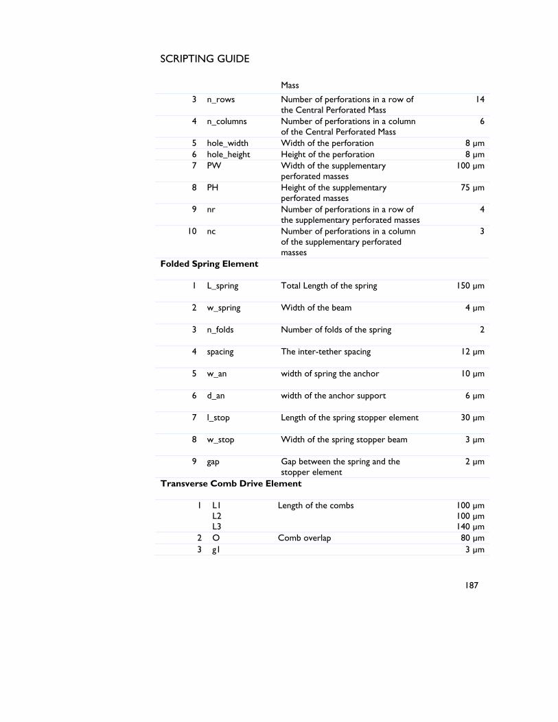
SCRIPTING GUIDE
Mass
3 n_rows Number of perforations in a row of the Central Perforated Mass
14
4 n_columns Number of perforations in a column of the Central Perforated Mass
6
5 hole_width Width of the perforation 8 µm 6 hole_height Height of the perforation 8 µm 7 PW Width of the supplementary
perforated masses 100 µm
8 PH Height of the supplementary perforated masses
75 µm
9 nr Number of perforations in a row of the supplementary perforated masses
4
10 nc Number of perforations in a column of the supplementary perforated masses
3
Folded Spring Element
1 L_spring Total Length of the spring 150 µm
2 w_spring Width of the beam 4 µm
3 n_folds Number of folds of the spring 2
4 spacing The inter-tether spacing 12 µm
5 w_an width of spring the anchor 10 µm
6 d_an width of the anchor support 6 µm
7 l_stop Length of the spring stopper element 30 µm
8 w_stop Width of the spring stopper beam 3 µm
9 gap Gap between the spring and the stopper element
2 µm
Transverse Comb Drive Element
1 L1 L2 L3
Length of the combs 100 µm 100 µm 140 µm
2 O Comb overlap 80 µm 3 g1 3 µm
187
SCRIPTING GUIDE
g2 g3
Comb spacings 3 µm 2 µm
4 w1 w2 w3
Width of the comb fingers
5 µm 9 µm 9 µm
5 N Number of fixed set of combs on the central plate
12
6 N1 Number of fixed set of combs on the supplementary plates
2
7 L_a Length of anchor 5 µm 8 W_a Width of anchor 3 µm 9 d Distance of anchor from the edge 3 µm
10 d_cf Distance of the first movable comb finger from the central and plate edge.
12 µm
11 d_cf1 Distance of the first movable comb finger from the supplementary plate edges
10 µm
Table 99 List of parameters of the 3 components of ADXL
188
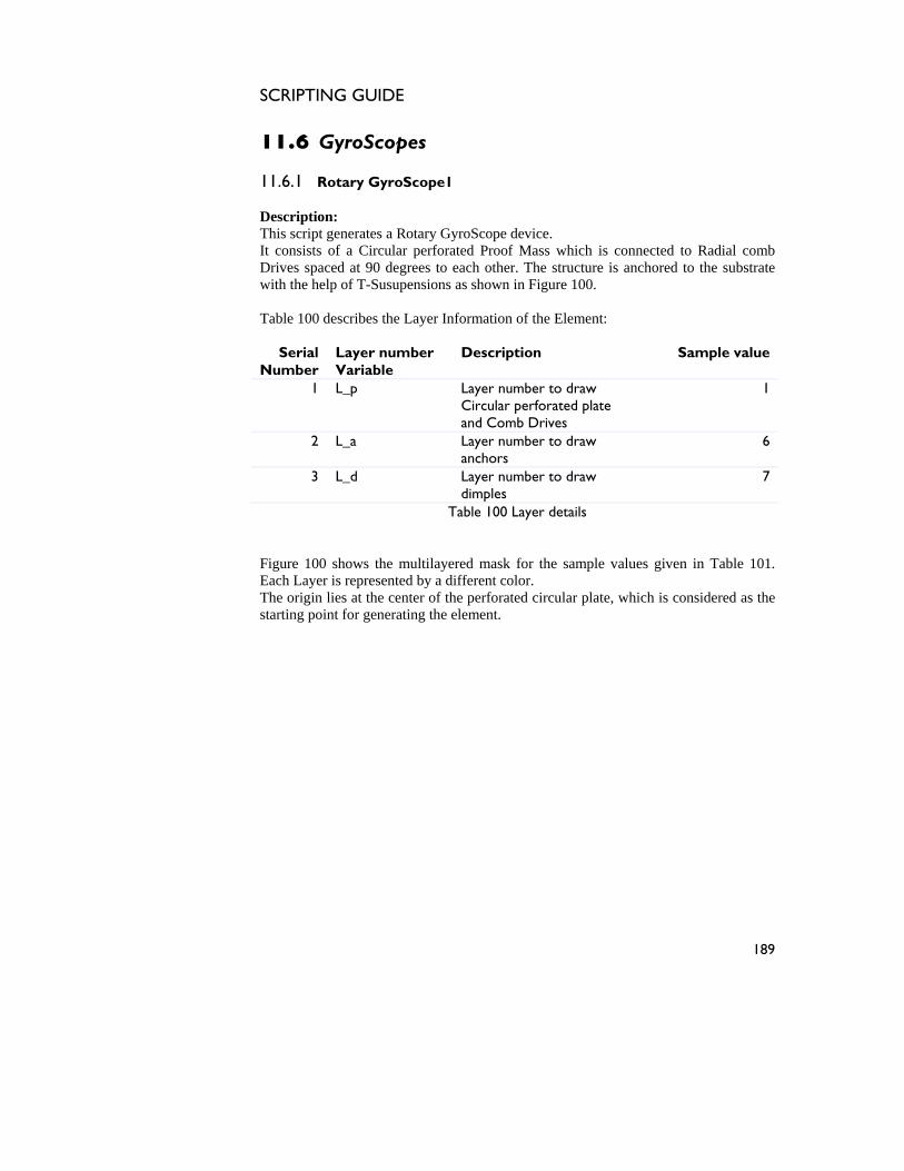
SCRIPTING GUIDE
11.6 GyroScopes 11.6.1 Rotary GyroScope1 Description: This script generates a Rotary GyroScope device. It consists of a Circular perforated Proof Mass which is connected to Radial comb Drives spaced at 90 degrees to each other. The structure is anchored to the substrate with the help of T-Susupensions as shown in Figure 100. Table 100 describes the Layer Information of the Element:
Serial Number
Layer number Variable
Description Sample value
1 L_p Layer number to draw Circular perforated plate and Comb Drives
1
2 L_a Layer number to draw anchors
6
3 L_d Layer number to draw dimples
7
Table 100 Layer details
Figure 100 shows the multilayered mask for the sample values given in Table 101. Each Layer is represented by a different color. The origin lies at the center of the perforated circular plate, which is considered as the starting point for generating the element.
189
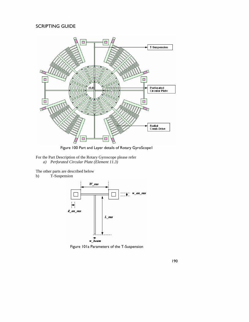
SCRIPTING GUIDE
Figure 100 Part and Layer details of Rotary GyroScope1
For the Part Description of the Rotary Gyroscope please refer
a) Perforated Circular Plate (Element 11.3) The other parts are described below b) T-Suspension
Figure 101a Parameters of the T-Suspension
190
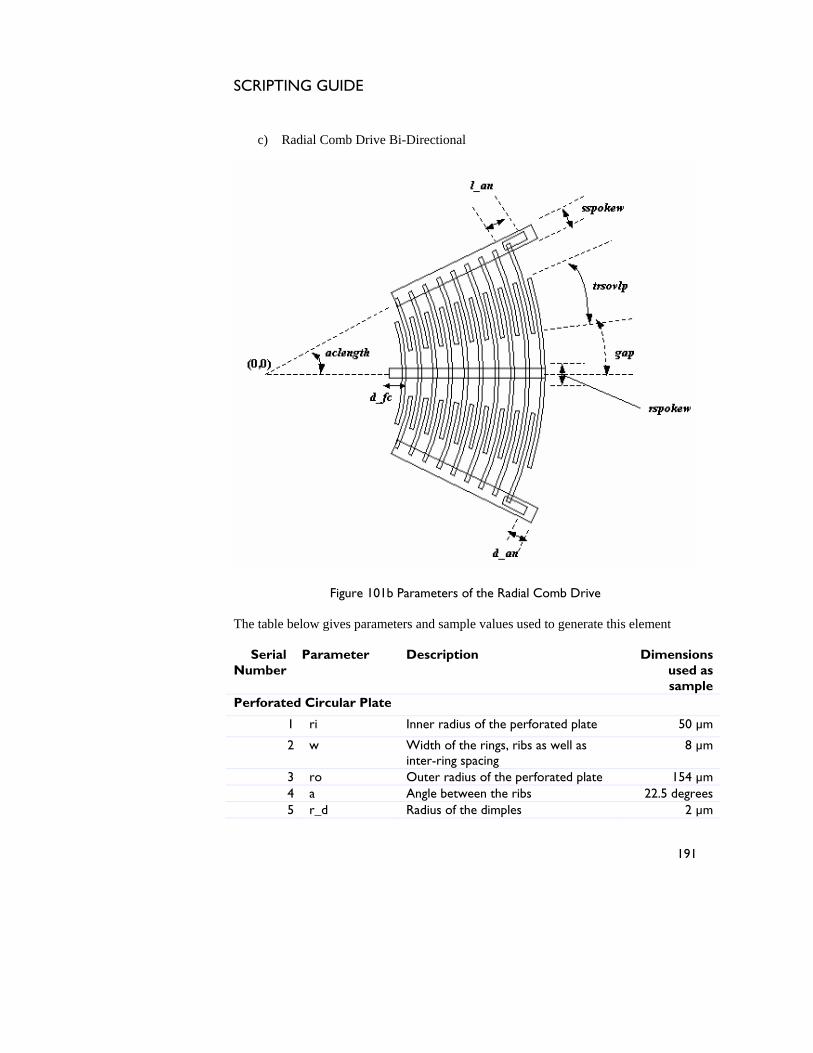
SCRIPTING GUIDE
c) Radial Comb Drive Bi-Directional
Figure 101b Parameters of the Radial Comb Drive
The table below gives parameters and sample values used to generate this element
Serial Number
Parameter Description Dimensions used as sample
Perforated Circular Plate
1 ri Inner radius of the perforated plate 50 µm
2 w Width of the rings, ribs as well as inter-ring spacing
8 µm
3 ro Outer radius of the perforated plate 154 µm 4 a Angle between the ribs 22.5 degrees 5 r_d Radius of the dimples 2 µm
191
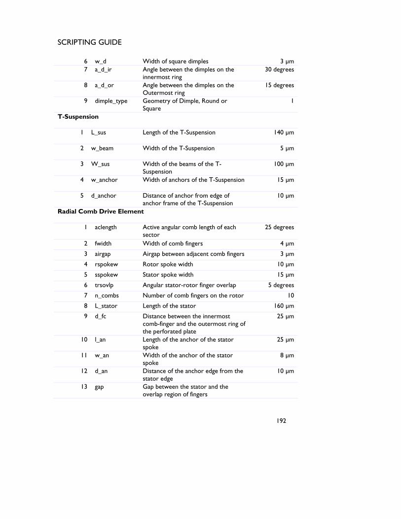
SCRIPTING GUIDE
6 w_d Width of square dimples 3 µm 7 a_d_ir Angle between the dimples on the
innermost ring 30 degrees
8 a_d_or Angle between the dimples on the Outermost ring
15 degrees
9 dimple_type Geometry of Dimple, Round or Square
1
T-Suspension
1 L_sus Length of the T-Suspension 140 µm
2 w_beam Width of the T-Suspension 5 µm
3 W_sus Width of the beams of the T-Suspension
100 µm
4 w_anchor Width of anchors of the T-Suspension 15 µm
5 d_anchor Distance of anchor from edge of anchor frame of the T-Suspension
10 µm
Radial Comb Drive Element
1 aclength Active angular comb length of each sector
25 degrees
2 fwidth Width of comb fingers 4 µm
3 airgap Airgap between adjacent comb fingers 3 µm
4 rspokew Rotor spoke width 10 µm
5 sspokew Stator spoke width 15 µm
6 trsovlp Angular stator-rotor finger overlap 5 degrees
7 n_combs Number of comb fingers on the rotor 10
8 L_stator Length of the stator 160 µm
9 d_fc Distance between the innermost comb-finger and the outermost ring of the perforated plate
25 µm
10 l_an Length of the anchor of the stator spoke
25 µm
11 w_an Width of the anchor of the stator spoke
8 µm
12 d_an Distance of the anchor edge from the stator edge
10 µm
13 gap Gap between the stator and the overlap region of fingers
192
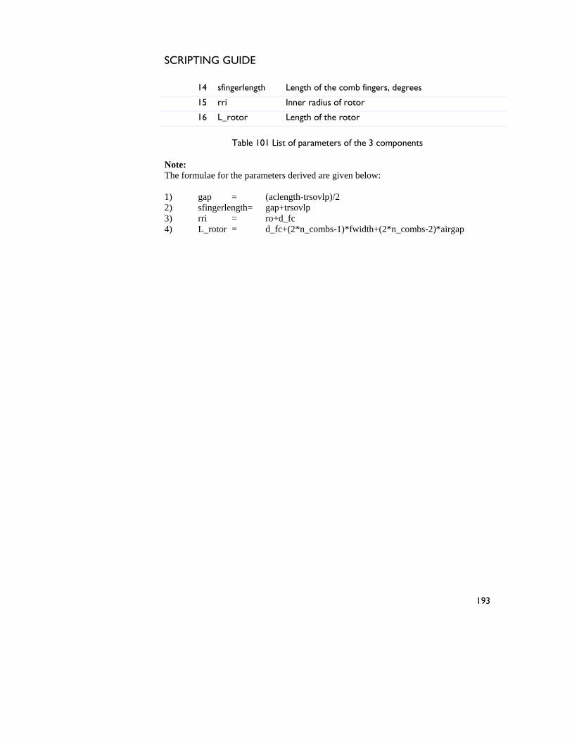
SCRIPTING GUIDE
14 sfingerlength Length of the comb fingers, degrees
15 rri Inner radius of rotor
16 L_rotor Length of the rotor
Table 101 List of parameters of the 3 components
Note: The formulae for the parameters derived are given below: 1) gap = (aclength-trsovlp)/2 2) sfingerlength= gap+trsovlp 3) rri = ro+d_fc 4) L_rotor = d_fc+(2*n_combs-1)*fwidth+(2*n_combs-2)*airgap
193
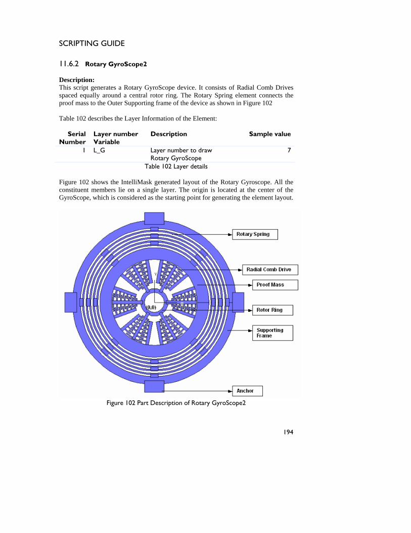
SCRIPTING GUIDE
11.6.2 Rotary GyroScope2 Description: This script generates a Rotary GyroScope device. It consists of Radial Comb Drives spaced equally around a central rotor ring. The Rotary Spring element connects the proof mass to the Outer Supporting frame of the device as shown in Figure 102 Table 102 describes the Layer Information of the Element:
Serial Number
Layer number Variable
Description Sample value
1 L_G Layer number to draw Rotary GyroScope
7
Table 102 Layer details
Figure 102 shows the IntelliMask generated layout of the Rotary Gyroscope. All the constituent members lie on a single layer. The origin is located at the center of the GyroScope, which is considered as the starting point for generating the element layout.
Figure 102 Part Description of Rotary GyroScope2
194
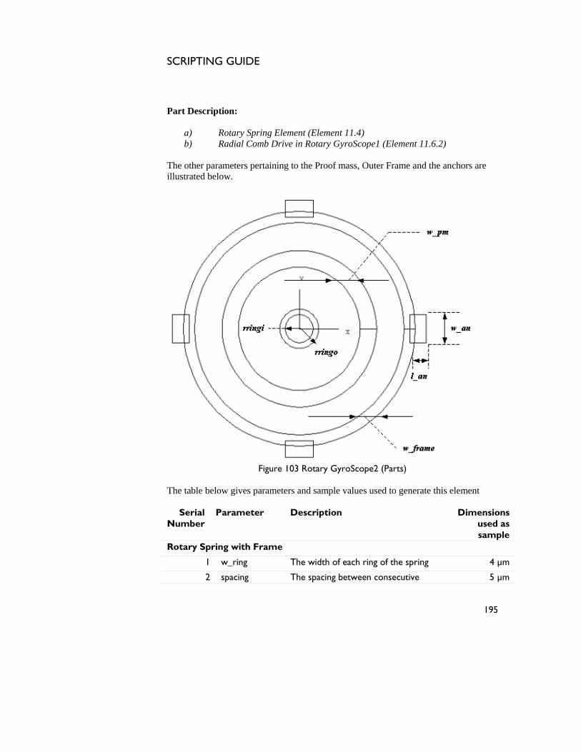
SCRIPTING GUIDE
Part Description:
a) Rotary Spring Element (Element 11.4) b) Radial Comb Drive in Rotary GyroScope1 (Element 11.6.2)
The other parameters pertaining to the Proof mass, Outer Frame and the anchors are illustrated below.
Figure 103 Rotary GyroScope2 (Parts)
The table below gives parameters and sample values used to generate this element
Serial Number
Parameter Description Dimensions used as sample
Rotary Spring with Frame
1 w_ring The width of each ring of the spring 4 µm
2 spacing The spacing between consecutive 5 µm
195
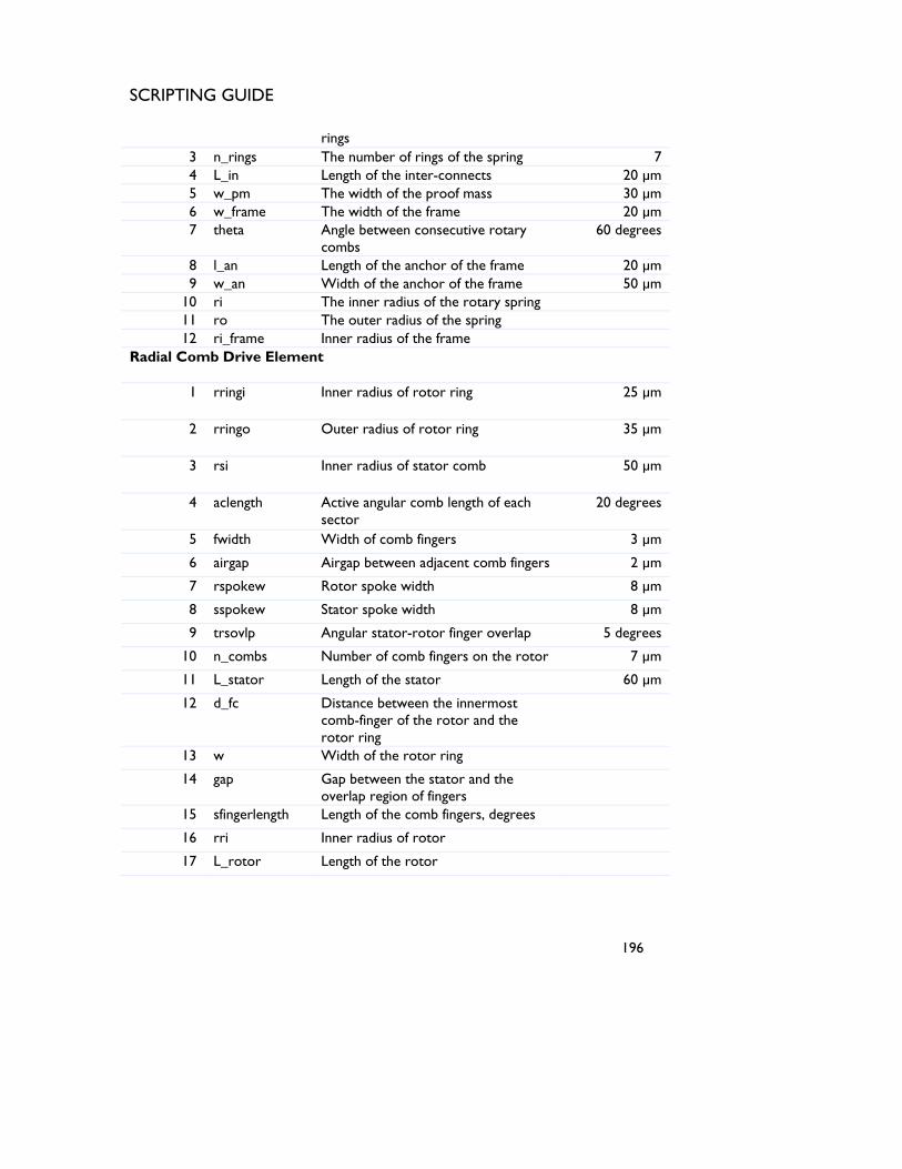
SCRIPTING GUIDE
rings 3 n_rings The number of rings of the spring 7 4 L_in Length of the inter-connects 20 µm 5 w_pm The width of the proof mass 30 µm 6 w_frame The width of the frame 20 µm 7 theta Angle between consecutive rotary
combs 60 degrees
8 l_an Length of the anchor of the frame 20 µm 9 w_an Width of the anchor of the frame 50 µm
10 ri The inner radius of the rotary spring 11 ro The outer radius of the spring 12 ri_frame Inner radius of the frame
Radial Comb Drive Element
1 rringi Inner radius of rotor ring 25 µm
2 rringo Outer radius of rotor ring 35 µm
3 rsi Inner radius of stator comb 50 µm
4 aclength Active angular comb length of each sector
20 degrees
5 fwidth Width of comb fingers 3 µm
6 airgap Airgap between adjacent comb fingers 2 µm
7 rspokew Rotor spoke width 8 µm
8 sspokew Stator spoke width 8 µm
9 trsovlp Angular stator-rotor finger overlap 5 degrees
10 n_combs Number of comb fingers on the rotor 7 µm
11 L_stator Length of the stator 60 µm
12 d_fc Distance between the innermost comb-finger of the rotor and the rotor ring
13 w Width of the rotor ring
14 gap Gap between the stator and the overlap region of fingers
15 sfingerlength Length of the comb fingers, degrees
16 rri Inner radius of rotor
17 L_rotor Length of the rotor
196

SCRIPTING GUIDE
Table 103 List of parameters of the components Note: The formulae for the parameters derived are given below: 1) ri = rsi+L_stator+w_pm+spacing 2) ro = (n_rings)*(w_ring)+(n_r-1)*spacing 3) ri_frame =rsi+L_stator+w_pm+(n_rings*w_ring)+((n_rings+1)*spacing)1) 4) w = rringo-rringi 5) gap = (aclength-trsovlp)/2 6) sfingerlength = gap+trsovlp 7) rri = rsi-fwidth-airgap 8) d_fc = rri-rringo 9) L_rotor = d_fc+(2*n_combs-1)*fwidth+(2*n_combs-2)*airgap
197
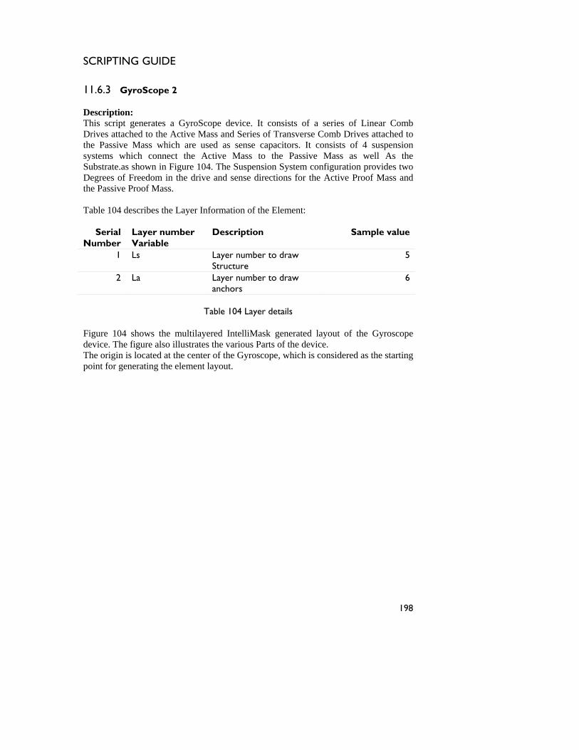
SCRIPTING GUIDE
11.6.3 GyroScope 2 Description: This script generates a GyroScope device. It consists of a series of Linear Comb Drives attached to the Active Mass and Series of Transverse Comb Drives attached to the Passive Mass which are used as sense capacitors. It consists of 4 suspension systems which connect the Active Mass to the Passive Mass as well As the Substrate.as shown in Figure 104. The Suspension System configuration provides two Degrees of Freedom in the drive and sense directions for the Active Proof Mass and the Passive Proof Mass. Table 104 describes the Layer Information of the Element:
Serial Number
Layer number Variable
Description Sample value
1 Ls Layer number to draw Structure
5
2 La Layer number to draw anchors
6
Table 104 Layer details
Figure 104 shows the multilayered IntelliMask generated layout of the Gyroscope device. The figure also illustrates the various Parts of the device. The origin is located at the center of the Gyroscope, which is considered as the starting point for generating the element layout.
198
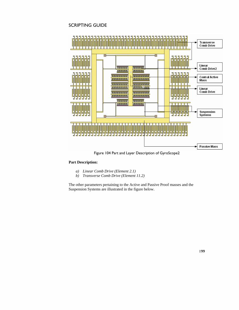
SCRIPTING GUIDE
Figure 104 Part and Layer Description of GyroScope2
Part Description:
a) Linear Comb Drive (Element 2.1) b) Transverse Comb Drive (Element 11.2)
The other parameters pertaining to the Active and Passive Proof masses and the Suspension Systems are illustrated in the figure below.
199
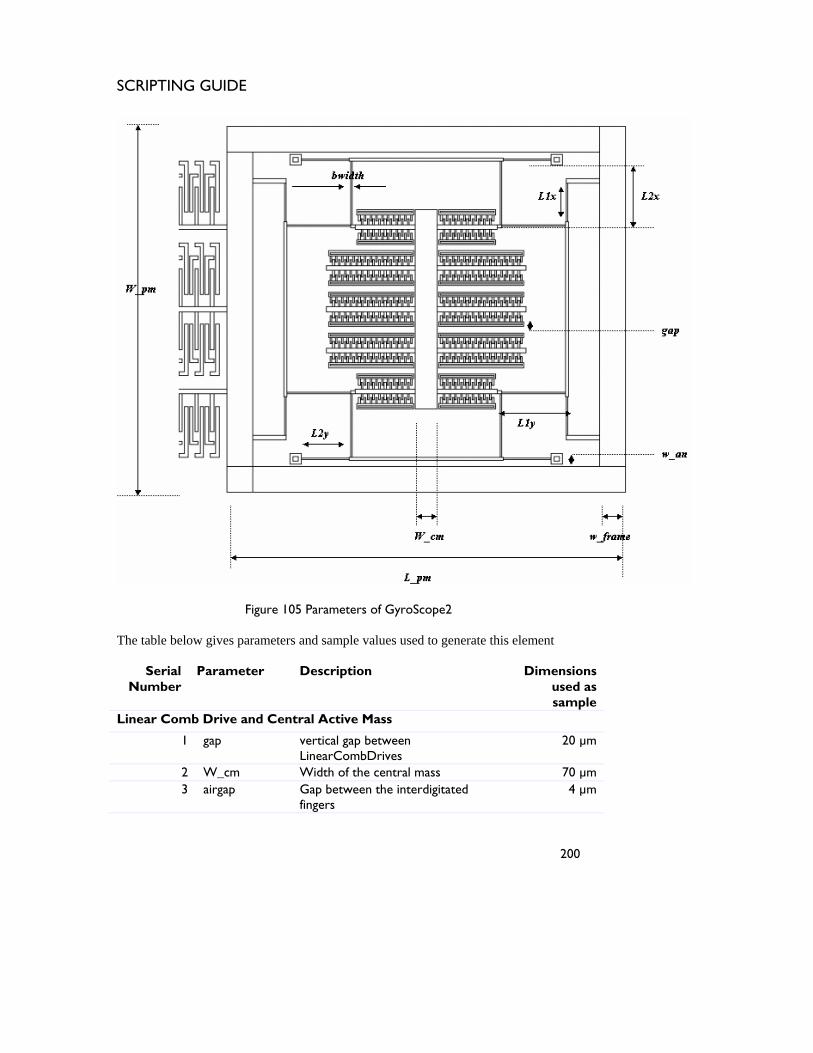
SCRIPTING GUIDE
200
Figure 105 Parameters of GyroScope2
The table below gives parameters and sample values used to generate this element
Serial Number
Parameter Description Dimensions used as sample
Linear Comb Drive and Central Active Mass
1 gap vertical gap between LinearCombDrives
20 µm
2 W_cm Width of the central mass 70 µm 3 airgap Gap between the interdigitated
fingers 4 µm
SCRIPTING GUIDE
201
4 fwidth The finger width 5 µm 5 sywidth Width of the stator yoke 15 µm 6 rywidth Width of the Rotor yoke 15 µm 7 flength Length of the finger 20 µm 8 rsoverlap Rotor-Stator finger overlap 8 µm 9 anwidth Width of the anchors 5 µm
10 da Distance of the anchor from edge 5 µm 11 numComb Number of combs of stator 20 12 numComb2 Number of combs of
lowermost/uppermost stator 15
Passive Mass
1 L_pm Length of Passive mass 1380 µm
2 W_pm Width of Passive mass 1300 µm
3 w_frame frame width of Passive mass 80 µm
Suspension Systems
1 bwidth width of beams along drive and sense directions
5 µm
2 L1x L1y
Lengths of beam in suspension connecting Active and Passive mass
120 µm 200 µm
3 L2x L2y
Lengths of beam in suspension connecting Active mass and Substrate
200 µm 150 µm
4 w_an width of suspension anchors 15 µm
5 d_an distance of anchor from edge 10 µm
Transverse Comb Drive Element
1 L1 L2 L3
Length of the combs 120 µm 120 µm 160 µm
2 O Comb overlap 80 µm 3 g1
g2 g3
Comb spacings
6 µm 6 µm 5 µm
4 w1 w2 w3
Width of the comb fingers
11 µm 10 µm 11 µm
5 N Number of movable fingers on Transverse CombDrive
10

SCRIPTING GUIDE
202
6 M Number of movable fingers on Top/Bottom ends of Transverse CombDrive
49
7 L_a Length of anchor 5 µm 8 W_a Width of anchor 3 µm 9 R Radius of curvature of the anchor 1 µm
10 d Distance of anchor from the edge 4 µm
Table 105 List of parameters of the components
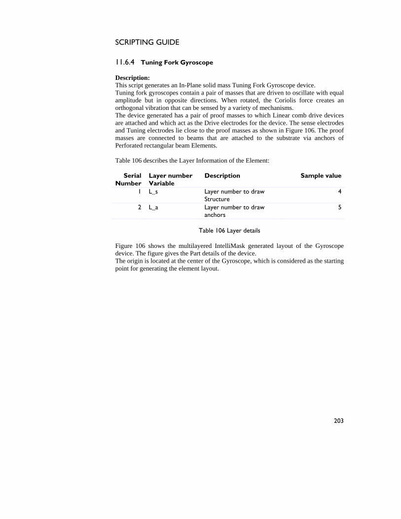
SCRIPTING GUIDE
203
11.6.4 Tuning Fork Gyroscope Description: This script generates an In-Plane solid mass Tuning Fork Gyroscope device. Tuning fork gyroscopes contain a pair of masses that are driven to oscillate with equal amplitude but in opposite directions. When rotated, the Coriolis force creates an orthogonal vibration that can be sensed by a variety of mechanisms. The device generated has a pair of proof masses to which Linear comb drive devices are attached and which act as the Drive electrodes for the device. The sense electrodes and Tuning electrodes lie close to the proof masses as shown in HTFigure 106TH. The proof masses are connected to beams that are attached to the substrate via anchors of Perforated rectangular beam Elements. Table 106 describes the Layer Information of the Element:
Serial Number
Layer number Variable
Description Sample value
1 L_s Layer number to draw Structure
4
2 L_a Layer number to draw anchors
5
Table 106 Layer details
HTFigure 106TH shows the multilayered IntelliMask generated layout of the Gyroscope device. The figure gives the Part details of the device. The origin is located at the center of the Gyroscope, which is considered as the starting point for generating the element layout.
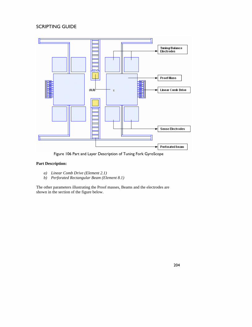
SCRIPTING GUIDE
204
Figure 106 Part and Layer Description of Tuning Fork GyroScope
Part Description:
a) HTLinear Comb Drive (Element 2.1)THHT b) HPerforated Rectangular Beam (Element 8.1)H
The other parameters illustrating the Proof masses, Beams and the electrodes are shown in the section of the figure below.
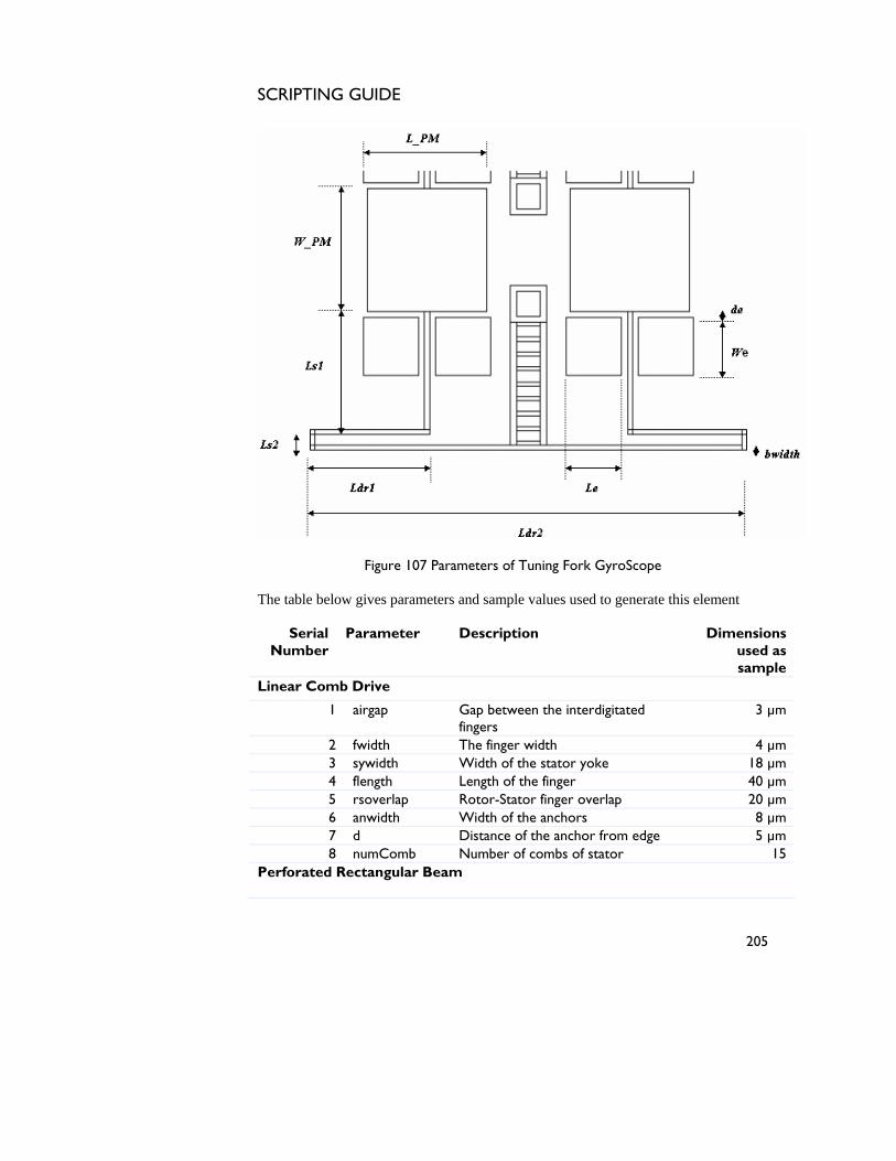
SCRIPTING GUIDE
205
Figure 107 Parameters of Tuning Fork GyroScope
The table below gives parameters and sample values used to generate this element
Serial Number
Parameter Description Dimensions used as sample
Linear Comb Drive
1 airgap Gap between the interdigitated fingers
3 µm
2 fwidth The finger width 4 µm 3 sywidth Width of the stator yoke 18 µm 4 flength Length of the finger 40 µm 5 rsoverlap Rotor-Stator finger overlap 20 µm 6 anwidth Width of the anchors 8 µm 7 d Distance of the anchor from edge 5 µm 8 numComb Number of combs of stator 15
Perforated Rectangular Beam
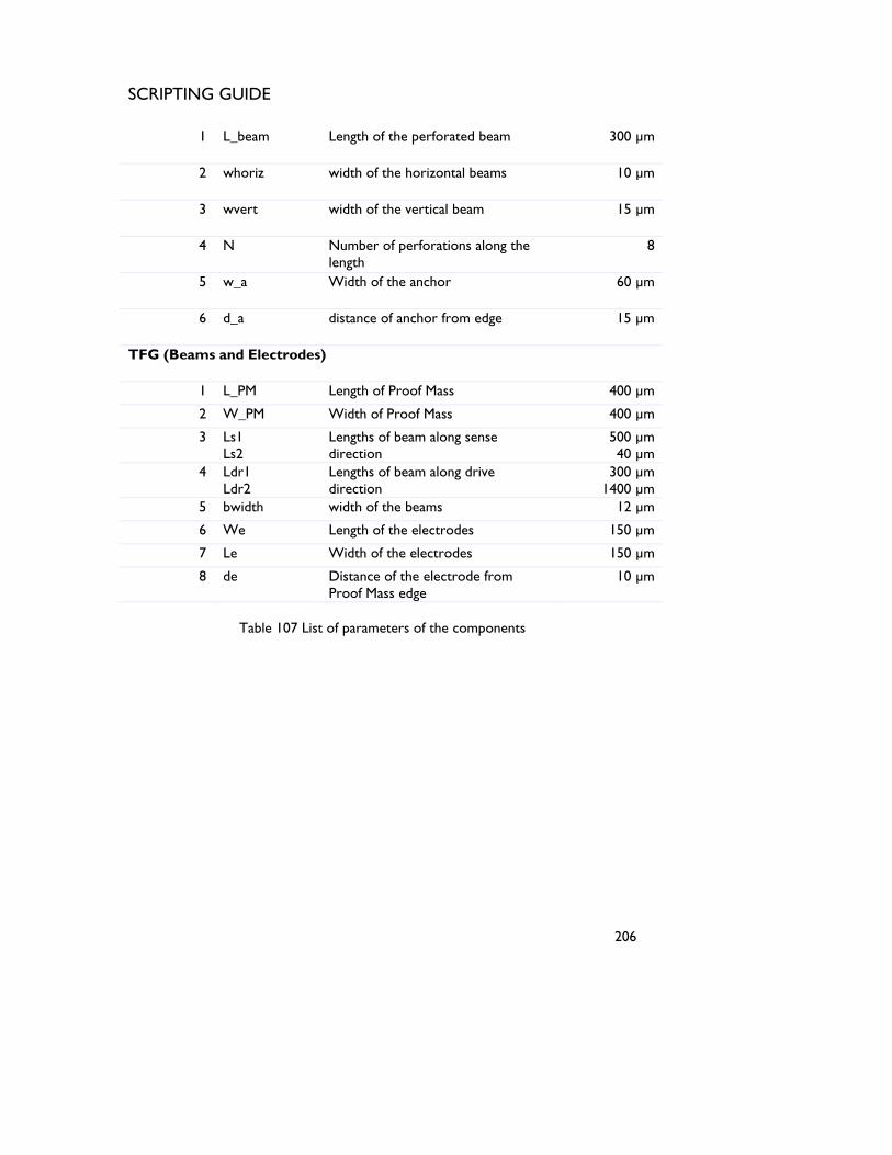
SCRIPTING GUIDE
206
1 L_beam Length of the perforated beam 300 µm
2 whoriz width of the horizontal beams 10 µm
3 wvert width of the vertical beam 15 µm
4 N Number of perforations along the length
8
5 w_a Width of the anchor 60 µm
6 d_a distance of anchor from edge 15 µm
TFG (Beams and Electrodes)
1 L_PM Length of Proof Mass 400 µm
2 W_PM Width of Proof Mass 400 µm
3 Ls1 Ls2
Lengths of beam along sense direction
500 µm 40 µm
4 Ldr1 Ldr2
Lengths of beam along drive direction
300 µm 1400 µm
5 bwidth width of the beams 12 µm
6 We Length of the electrodes 150 µm
7 Le Width of the electrodes 150 µm
8 de Distance of the electrode from Proof Mass edge
10 µm
Table 107 List of parameters of the components
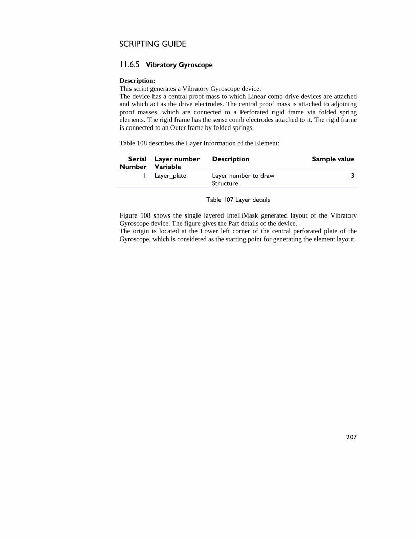
SCRIPTING GUIDE
207
11.6.5 Vibratory Gyroscope Description: This script generates a Vibratory Gyroscope device. The device has a central proof mass to which Linear comb drive devices are attached and which act as the drive electrodes. The central proof mass is attached to adjoining proof masses, which are connected to a Perforated rigid frame via folded spring elements. The rigid frame has the sense comb electrodes attached to it. The rigid frame is connected to an Outer frame by folded springs. Table 108 describes the Layer Information of the Element:
Serial Number
Layer number Variable
Description Sample value
1 Layer_plate Layer number to draw Structure
3
Table 107 Layer details
HFigure 108H shows the single layered IntelliMask generated layout of the Vibratory Gyroscope device. The figure gives the Part details of the device. The origin is located at the Lower left corner of the central perforated plate of the Gyroscope, which is considered as the starting point for generating the element layout.
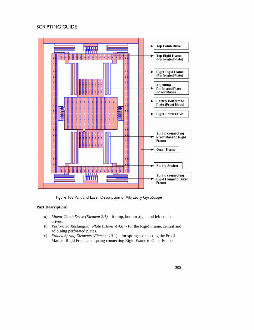
SCRIPTING GUIDE
208
Figure 108 Part and Layer Description of Vibratory GyroScope
Part Description:
a) HLinear Comb Drive (Element 2.1)H – for top, bottom ,right and left comb drives.
b) HPerforated Rectangular Plate (Element 4.6)H - for the Rigid Frame, central and adjoining perforated plates.
c) HFolded Spring Elements (Element 10.1)H – for springs connecting the Proof Mass to Rigid Frame and spring connecting Rigid Frame to Outer Frame.
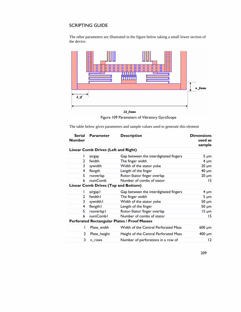
SCRIPTING GUIDE
209
The other parameters are illustrated in the figure below taking a small lower section of the device.
Figure 109 Parameters of Vibratory GyroScope The table below gives parameters and sample values used to generate this element
Serial Number
Parameter Description Dimensions used as sample
Linear Comb Drives (Left and Right)
1 airgap Gap between the interdigitated fingers 5 µm 2 fwidth The finger width 4 µm 3 sywidth Width of the stator yoke 20 µm 4 flength Length of the finger 40 µm 5 rsoverlap Rotor-Stator finger overlap 20 µm 6 numComb Number of combs of stator 15
Linear Comb Drives (Top and Bottom)
1 airgap1 Gap between the interdigitated fingers 4 µm 2 fwidth1 The finger width 5 µm 3 sywidth1 Width of the stator yoke 50 µm 4 flength1 Length of the finger 50 µm 5 rsoverlap1 Rotor-Stator finger overlap 15 µm 6 numComb1 Number of combs of stator 15
Perforated Rectangular Plates / Proof Masses
1 Plate_width Width of the Central Perforated Mass 600 µm
2 Plate_height Height of the Central Perforated Mass 400 µm
3 n_rows Number of perforations in a row of 12
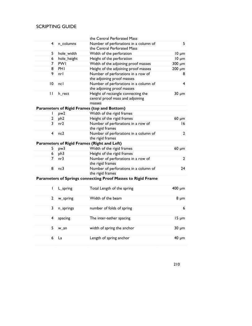
SCRIPTING GUIDE
210
the Central Perforated Mass 4 n_columns Number of perforations in a column of
the Central Perforated Mass 5
5 hole_width Width of the perforation 10 µm 6 hole_height Height of the perforation 10 µm 7 PW1 Width of the adjoining proof masses 300 µm 8 PH1 Height of the adjoining proof masses 200 µm 9 nr1 Number of perforations in a row of
the adjoining proof masses 8
10 nc1 Number of perforations in a column of the adjoining proof masses
4
11 h_rect Height of rectangle connecting the central proof mass and adjoining masses
30 µm
Parameters of Rigid Frames (top and Bottom) 1 pw2 Width of the rigid frames 2 ph2 Height of the rigid frames 60 µm 3 nr2 Number of perforations in a row of
the rigid frames 16
4 nc2 Number of perforations in a column of the rigid frames
2
Parameters of Rigid Frames (Right and Left) 5 pw3 Width of the rigid frames 60 µm 6 ph3 Height of the rigid frames 7 nr3 Number of perforations in a row of
the rigid frames 2
8 nc3 Number of perforations in a column of the rigid frames
24
Parameters of Springs connecting Proof Masses to Rigid Frame
1 L_spring Total Length of the spring 400 µm
2 w_spring Width of the beam 8 µm
3 n_springs number of folds of spring 6
4 spacing The inter-tether spacing 15 µm
5 w_an width of spring the anchor 30 µm
6 La Length of spring anchor 40 µm
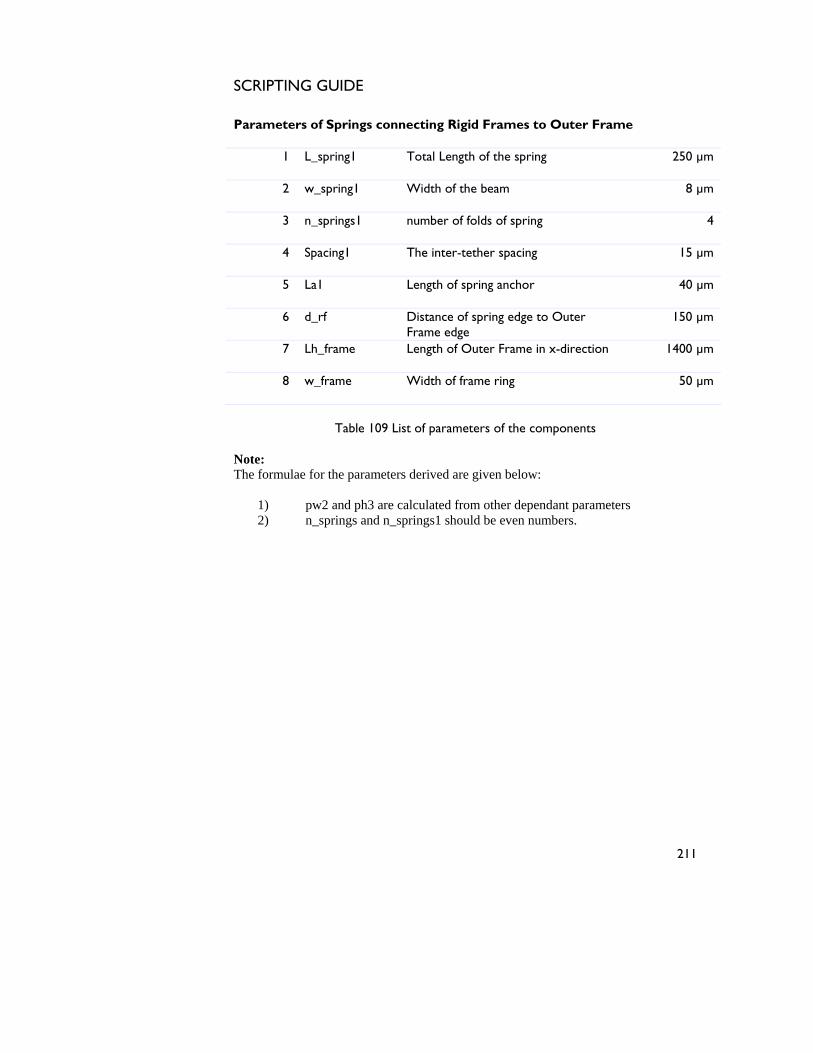
SCRIPTING GUIDE
211
Parameters of Springs connecting Rigid Frames to Outer Frame
1 L_spring1 Total Length of the spring 250 µm
2 w_spring1 Width of the beam 8 µm
3 n_springs1 number of folds of spring 4
4 Spacing1 The inter-tether spacing 15 µm
5 La1 Length of spring anchor 40 µm
6 d_rf Distance of spring edge to Outer Frame edge
150 µm
7 Lh_frame Length of Outer Frame in x-direction 1400 µm
8 w_frame Width of frame ring 50 µm
Table 109 List of parameters of the components
Note: The formulae for the parameters derived are given below:
1) pw2 and ph3 are calculated from other dependant parameters 2) n_springs and n_springs1 should be even numbers.

SCRIPTING GUIDE
212