Embed Size (px)
Citation preview
EAR Controlled - ECCN EAR99 This technical data is subject to US Government export control in accordance with the Export Administration Regulations. Export of this data to any foreign country, or disclosure of this data to a Non-US person, may be a violation of Federal law. Sea Tel, Inc. (trading as Cobham SATCOM) 4030 Nelson Avenue Concord, CA 94520 Tel: +1 (925) 798-7979 Fax: +1 (925) 798-7986
Thrane & Thrane A/S (trading as Cobham SATCOM) Lundtoftegaardsvej 93 D, 2800 Kgs. Lyngby, Denmark Tel: +45 3955 8800 Fax: +45 3955 8888 Web: http://www.cobham.com/satcom Email: [email protected]
February 14, 2018 Document. No. 99-148766-B
EAR Controlled - ECCN EAR99
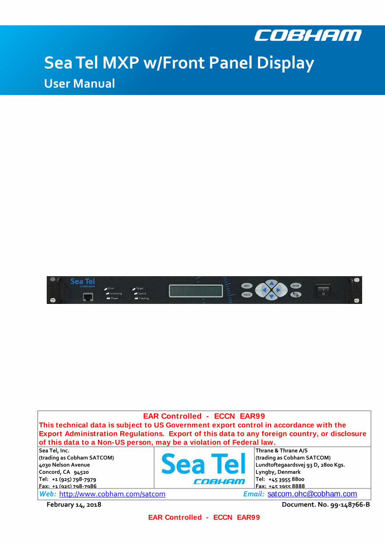
Sea Tel MXP w/Front Panel Display User Manual
MXP w/Front Panel Display User Manual
ii
EAR Controlled - ECCN EAR99
These commodities, technology or software were exported from the United States in accordance with the Export Administration Regulations. Diversion contrary to U.S. law is prohibited.
Sea Tel Marine Stabilized Antenna systems are assembled in the United States of America.
Sea Tel is an ISO 9001:2008 registered company. Certificate Number 13690 originally issued March 14, 2011 and was renewed/reissued on March 10, 2014.
RED 2014/53/EU
Cobham SATCOM declares that the Sea Tel VSAT Maritime Satellite Earth Stations are in compliance with The Radio Equipment Directive 2014/53/EU. The full text of this Self Declaration of Conformity for this equipment is contained in this manual.
Copyright Notice
Copyright © 2015 Sea Tel Inc All Rights Reserved. The information contained in this document is proprietary to Sea Tel, Inc.. This document may not be reproduced or distributed in any form without prior written consent of Sea Tel, Inc. The information in this document is subject to change without notice. Sea Tel Inc, is also doing business as Cobham SATCOM – Maritime.
Revision History
REV DCO# Date Description By
X1 N/A October 19, 2015 PRELIMINARY release for Beta users MDN
A N/A May 3, 2016 Production Release MDN
B 00024566 January22, 2018 Update text and add cyber security caution. MDN
Table of Contents MXP w/Front Panel Display User Manual
iii
EAR Controlled - ECCN EAR99
1. INTRODUCTION ............................................................................................................................. 1-1 1.1. AUDIENCE ............................................................................................................................................ 1-1 1.2. INTERNAL WEB PAGE PREREQUISITES ...................................................................................................... 1-1
Browsers .................................................................................................................................. 1-1 1.2.1.
Monitors .................................................................................................................................. 1-1 1.2.2.
Computer Parameters ............................................................................................................... 1-1 1.2.3.
SSL certificate .......................................................................................................................... 1-2 1.2.4.
Signal Bar ................................................................................................................................ 1-2 1.2.5.
1.3. USING THIS MANUAL ............................................................................................................................. 1-2 1.4. CYBER SECURITY CAUTION ..................................................................................................................... 1-2
2. QUICK START ................................................................................................................................. 2-1 2.1. TURN POWER ON ................................................................................................................................. 2-1 2.2. POWER-UP SEQUENCE ........................................................................................................................... 2-1 2.3. IF SATELLITE SIGNAL NOT FOUND .......................................................................................................... 2-2 2.4. IF SATELLITE SIGNAL IS FOUND BUT RECEIVE LOCK IS NOT ACHIEVED: ............................................................ 2-2 2.5. TARGET A DIFFERENT SATELLITE ............................................................................................................. 2-2 2.6. BASIC FUNCTION OF FRONT PANEL KEYS .................................................................................................. 2-2 2.7. NORMAL FRONT PANEL LED STATES ....................................................................................................... 2-3
3. OPERATION FROM THE FRONT PANEL ........................................................................................... 3-1 3.1. DISPLAY AND ENTRY OPERATION MENUS ................................................................................................. 3-1 3.2. POWER-UP & STATUS ............................................................................................................................ 3-1
Power-Up displays .................................................................................................................... 3-1 3.2.1.
Status Information Menus ........................................................................................................ 3-2 3.2.2.
3.3. SHIP INFORMATION MENUS .................................................................................................................... 3-3 3.4. SATELLITE INFORMATION MENUS. ........................................................................................................... 3-5 3.5. ANTENNA INFORMATION MENUS. ............................................................................................................ 3-8
4. OPERATION FROM THE INTERNAL WEB-BASED GUI....................................................................... 4-1 4.1. LOGIN TO MXP..................................................................................................................................... 4-1 4.2. COMMON INFORMATION ON ALL MXP SYSTEM PAGES ............................................................................... 4-1
Banner ..................................................................................................................................... 4-1 4.2.1.
Left Side Bar ............................................................................................................................ 4-3 4.2.2.
Task Bar ................................................................................................................................... 4-4 4.2.3.
4.3. MXP SYSTEM PAGES ............................................................................................................................. 4-4 Satellite Search > Auto (Satellite Signal Automatic Search page) ............................................... 4-4 4.3.1.
Configuration > Satellite (Satellite Configuration page) .............................................................. 4-5 4.3.2.
Configuration > Interfaces (Ship Position Settings page)........................................................... 4-10 4.3.3.
Status > Graphs (Monitoring Graph page) ............................................................................... 4-10 4.3.4.
Status > System (System Status page) .................................................................................... 4-12 4.3.5.
Tools > Position Antenna .........................................................................................................4-13 4.3.6.
Logs > Activity (View Activity Log page) .................................................................................. 4-14 4.3.7.
Logs > Data Export (System Log and Criteria for Graphic Data Export pages)............................. 4-17 4.3.8.
Others > Change Password ...................................................................................................... 4-17 4.3.9.
Cyber Security Caution ............................................................................................................ 4-18 4.3.10.
Others > Help (Help / FAQ page) .............................................................................................. 4-18 4.3.11.
Recycle Power ........................................................................................................................ 4-19 4.3.12.
MXP w/Front Panel Display User Manual Table of Contents
iv
EAR Controlled - ECCN EAR99
5. SETUP FROM THE FRONT PANEL .................................................................................................... 5-1 5.1. ACCESS TO THE SETUP PARAMETERS ........................................................................................................ 5-1 5.2. DISPLAY/EDIT THE SETUP PARAMETERS .................................................................................................... 5-1
6. TROUBLESHOOTING FOR USERS .................................................................................................... 6-1 6.1. CHECK TO SEE THAT THE MXP POWERS UP............................................................................................... 6-1 6.2. CHECK TO SEE THAT THE OTHER BELOW DECKS EQUIPMENT POWERS UP ...................................................... 6-1 6.3. CHECK THE FRONT PANEL LED STATES ................................................................................................... 6-1 6.4. CHECK FOR BLOCKAGE .......................................................................................................................... 6-2 6.5. CHECK FOR ERRORS .............................................................................................................................. 6-3
7. GLOSSARY OF TERMS ..................................................................................................................... 7-1 8. TECHNICAL CONTACTS ................................................................................................................... 8-1
Introduction MXP w/Front Panel Display User Manual
1-1
EAR Controlled - ECCN EAR99
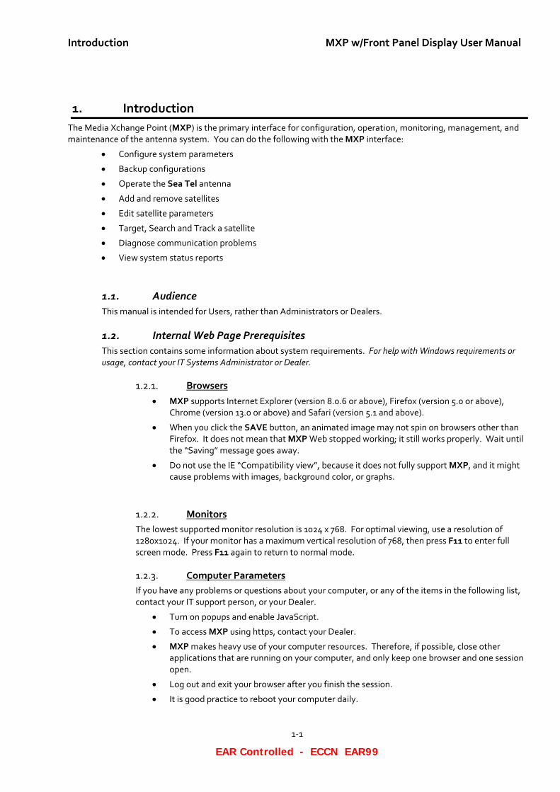
1. Introduction The Media Xchange Point (MXP) is the primary interface for configuration, operation, monitoring, management, and maintenance of the antenna system. You can do the following with the MXP interface:
• Configure system parameters
• Backup configurations
• Operate the Sea Tel antenna
• Add and remove satellites
• Edit satellite parameters
• Target, Search and Track a satellite
• Diagnose communication problems
• View system status reports
1.1. Audience This manual is intended for Users, rather than Administrators or Dealers.
1.2. Internal Web Page Prerequisites This section contains some information about system requirements. For help with Windows requirements or usage, contact your IT Systems Administrator or Dealer.
Browsers 1.2.1.• MXP supports Internet Explorer (version 8.0.6 or above), Firefox (version 5.0 or above),
Chrome (version 13.0 or above) and Safari (version 5.1 and above).
• When you click the SAVE button, an animated image may not spin on browsers other than Firefox. It does not mean that MXP Web stopped working; it still works properly. Wait until the “Saving” message goes away.
• Do not use the IE “Compatibility view”, because it does not fully support MXP, and it might cause problems with images, background color, or graphs.
Monitors 1.2.2.The lowest supported monitor resolution is 1024 x 768. For optimal viewing, use a resolution of 1280x1024. If your monitor has a maximum vertical resolution of 768, then press F11 to enter full screen mode. Press F11 again to return to normal mode.
Computer Parameters 1.2.3.If you have any problems or questions about your computer, or any of the items in the following list, contact your IT support person, or your Dealer.
• Turn on popups and enable JavaScript.
• To access MXP using https, contact your Dealer.
• MXP makes heavy use of your computer resources. Therefore, if possible, close other applications that are running on your computer, and only keep one browser and one session open.
• Log out and exit your browser after you finish the session.
• It is good practice to reboot your computer daily.
MXP w/Front Panel Display User Manual Introduction
1-2
EAR Controlled - ECCN EAR99
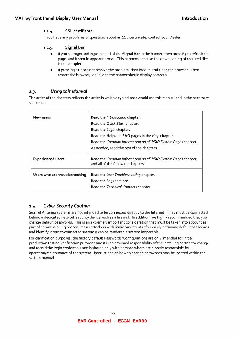
SSL certificate 1.2.4.If you have any problems or questions about an SSL certificate, contact your Dealer.
Signal Bar 1.2.5.• If you see 15px and 25px instead of the Signal Bar in the banner, then press F5 to refresh the
page, and it should appear normal. This happens because the downloading of required files is not complete.
• If pressing F5 does not resolve the problem, then logout, and close the browser. Then restart the browser, log in, and the banner should display correctly.
1.3. Using this Manual The order of the chapters reflects the order in which a typical user would use this manual and in the necessary sequence.
New users Read the Introduction chapter.
Read the Quick Start chapter.
Read the Login chapter.
Read the Help and FAQ pages in the Help chapter.
Read the Common Information on all MXP System Pages chapter.
As needed, read the rest of the chapters.
Experienced users Read the Common Information on all MXP System Pages chapter, and all of the following chapters.
Users who are troubleshooting Read the User Troubleshooting chapter.
Read the Logs sections.
Read the Technical Contacts chapter.
1.4. Cyber Security Caution Sea Tel Antenna systems are not intended to be connected directly to the Internet. They must be connected behind a dedicated network security device such as a firewall. In addition, we highly recommended that you change default passwords. This is an extremely important consideration that must be taken into account as part of commissioning procedures as attackers with malicious intent (after easily obtaining default passwords and identify internet-connected systems) can be rendered a system inoperable.
For clarification purposes, the factory default Passwords/Configurations are only intended for initial production testing/verification purposes and it is an assumed responsibility of the installing partner to change and record the login credentials and is shared only with persons whom are directly responsible for operation/maintenance of the system. Instructions on how to change passwords may be located within the system manual.
Quick Start MXP w/Front Panel Display User Manual
2-1
EAR Controlled - ECCN EAR99
2. Quick Start If your system was set up correctly, and if your ship has not moved since the system was set up or used last, then the system should:
• Automatically power up from a cold start;
• Acquire the last satellite that you used;
• Achieve receive network lock;
• Start tracking.
• Then the system is fully operational
Perform the steps in the rest of this chapter to go from a cold start to an operational system.
2.1. Turn Power ON To apply power to the antenna system:
1. If all of the Above Deck Equipment (ADE) and Below Decks Equipment (BDE) are connected to a Universal Power Supply (UPS), then turn the UPS ON first (or verify that it is ON).
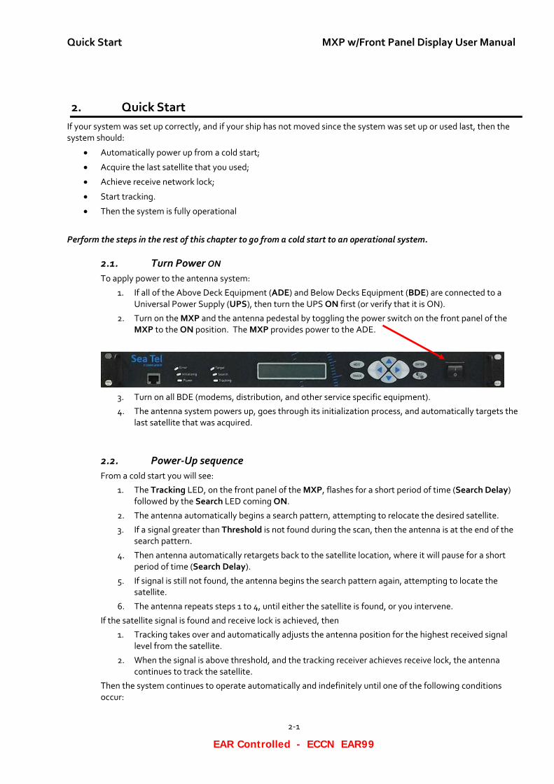
2. Turn on the MXP and the antenna pedestal by toggling the power switch on the front panel of the MXP to the ON position. The MXP provides power to the ADE.
3. Turn on all BDE (modems, distribution, and other service specific equipment).
4. The antenna system powers up, goes through its initialization process, and automatically targets the last satellite that was acquired.
2.2. Power-Up sequence From a cold start you will see:
1. The Tracking LED, on the front panel of the MXP, flashes for a short period of time (Search Delay) followed by the Search LED coming ON.
2. The antenna automatically begins a search pattern, attempting to relocate the desired satellite.
3. If a signal greater than Threshold is not found during the scan, then the antenna is at the end of the search pattern.
4. Then antenna automatically retargets back to the satellite location, where it will pause for a short period of time (Search Delay).
5. If signal is still not found, the antenna begins the search pattern again, attempting to locate the satellite.
6. The antenna repeats steps 1 to 4, until either the satellite is found, or you intervene.
If the satellite signal is found and receive lock is achieved, then
1. Tracking takes over and automatically adjusts the antenna position for the highest received signal level from the satellite.
2. When the signal is above threshold, and the tracking receiver achieves receive lock, the antenna continues to track the satellite.
Then the system continues to operate automatically and indefinitely until one of the following conditions occur:
MXP w/Front Panel Display User Manual Quick Start
2-2
EAR Controlled - ECCN EAR99
• AC power to the system is interrupted;
• The satellite signal is blocked.
• The ship sails into an area with insufficient satellite signal strength or level.
2.3. If Satellite Signal NOT Found If the system cannot find the satellite, then follow the steps below:
1. Press NEXT until the Ship menu is displayed to check the Latitude, Longitude and Heading values. If necessary:
• Correct the Latitude and Longitude location of the ship.
• Correct the Heading to be the same as the current heading value of the of the ships Gyro Compass.
2. Press NEXT to the Satellite display menu so you can check the satellite being targeted and the tracking frequency being used. If either of these are incorrect:
• Correct the Longitude of the Satellite to target the desired satellite.
• Correct the Frequency so that the system will be able to track the desired satellite.
If the desired satellite is still not found:
1. Check for Blockage. (Blockage is the most common cause of not being able to acquire the desired satellite.) (See the Check for Blockage section in the Troubleshooting chapter for details.)
2. Check the cable connections to assure that a cable is not disconnected.
3. Check the satellite modem power, connections and settings.
4. Read the Troubleshooting chapter for other possible causes and directions.
If you cannot identify or resolve the problem, then contact your Dealer.
2.4. If satellite signal IS found but receive lock is NOT achieved: If you’re system has been setup to use the receive lock/satellite ID output from the satellite modem; When signal above threshold is found but the modem does NOT get receive lock (receive sync), the ACU will re-target in an attempt to find the satellite which has signal AND receive lock. This could be due to the antenna targeting the wrong satellite, polarization failure, modem failure (not getting receive sync) or network failure (not allowing the modem to get receive sync). The ACU will continue to re-target.
2.5. Target a Different Satellite If your system is managed remotely (e.g., OpenAMIP, ROAM, and so forth), then you may not be able to target, or use another satellite for your broadband services without changing the satellite modem settings. If your system is managed remotely, then check with your airtime provider to make any necessary changes.
If your system is managed locally, check your records for the proper settings for the satellite, or beam, that you wish to begin using. To target a different satellite, or beam, refer to the Operation chapter to make the appropriate changes and re-target the antenna.
2.6. Basic Function of Front Panel Keys Keyboard operation is very simple and straightforward. Basic function of each key is:
Press NEXT to cycle through the four main menus: Ship, Satellite, Antenna and Status (refer to the Operation Flowcharts).
Press TRACK key to toggle the state of Tracking, ON/OFF. If SEARCH is ON, pressing the TRACK key will turn search OFF.
Quick Start MXP w/Front Panel Display User Manual
2-3
EAR Controlled - ECCN EAR99
When the Antenna main menu is displayed, pressing the LEFT arrow moves the antenna left (CCW or down in azimuth). Pressing the RIGHT arrow to move the antenna right (CW or up in azimuth).
In any sub-menu, pressing the LEFT or RIGHT arrow enters editing mode and brings up a cursor in the display. When the cursor is under a character, it is selected and can be changed (see UP/DOWN arrow below).
(Setup) - Press and release BOTH the LEFT and RIGHT arrow keys to access the SAVE parameters window. Press and hold for six seconds to access the setup parameters (refer to the Setup section of the systems installation manual).
When the Antenna main menu is displayed, press UP arrow to move the antenna up in elevation or the DOWN arrow to move the antenna down in elevation.
Press the UP/DOWN arrow cycle Up and Down through the sub-menus.
When a sub-menu item is being edited, use the UP/DOWN to increment/decrement the selected character. This steps the selected entry one increment per sequential key-press or rapidly increments the selected entry when pressed and held.
At any main menu level, press ENTER to access the sub-menu items.
When viewing one of the sub-menus, pressing the ENTER key will step down through the sub-menu items, like the DOWN arrow does.
When editing, the cursor is visible under a character in a sub-menu (whether it has been changed or not), press ENTER to execute the present value, and return to display mode of that sub-menu. This does NOT save the new value to NVRAM.
Press Brightness/Backlight button once to select, and then the UP/DOWN arrow key to adjust, the brightness of the display. Press the Brightness/Backlight again to select, and then the UP/DOWN arrow key to adjust, the backlight level of the display. Press the Brightness/Backlight button a third time to exit Brightness/Backlight mode.
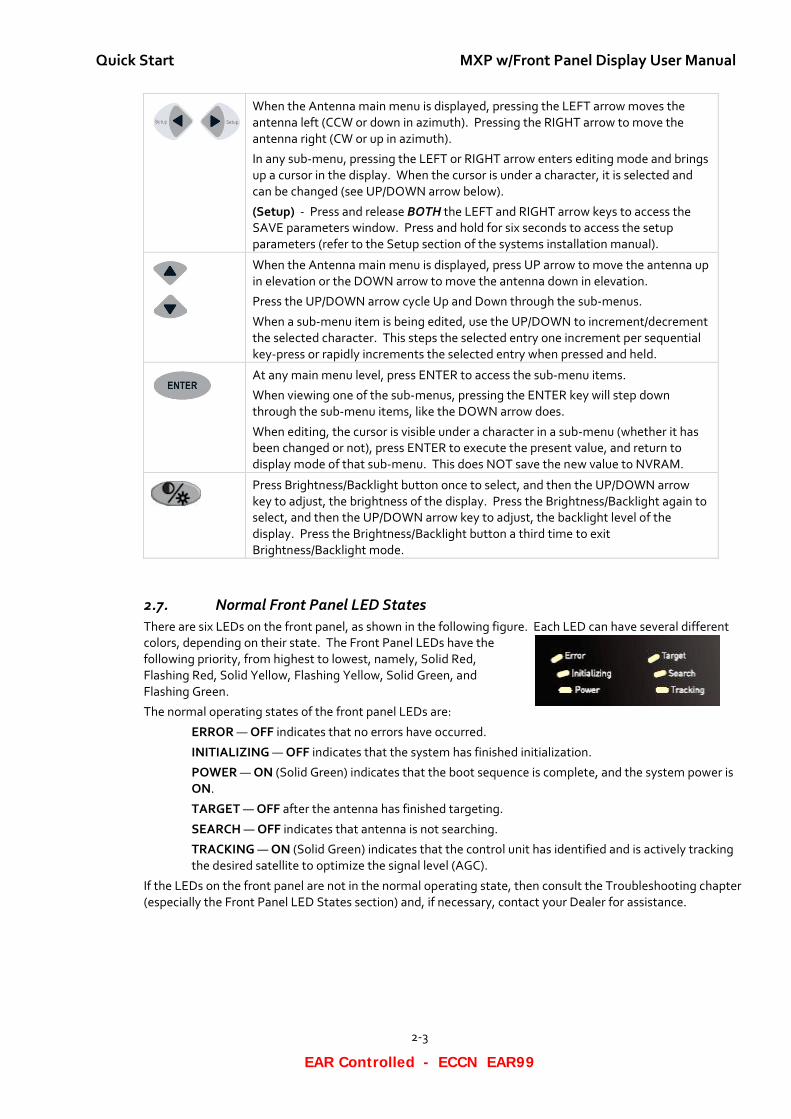
2.7. Normal Front Panel LED States There are six LEDs on the front panel, as shown in the following figure. Each LED can have several different colors, depending on their state. The Front Panel LEDs have the following priority, from highest to lowest, namely, Solid Red, Flashing Red, Solid Yellow, Flashing Yellow, Solid Green, and Flashing Green.
The normal operating states of the front panel LEDs are:
ERROR — OFF indicates that no errors have occurred.
INITIALIZING — OFF indicates that the system has finished initialization.
POWER — ON (Solid Green) indicates that the boot sequence is complete, and the system power is ON.
TARGET — OFF after the antenna has finished targeting.
SEARCH — OFF indicates that antenna is not searching.
TRACKING — ON (Solid Green) indicates that the control unit has identified and is actively tracking the desired satellite to optimize the signal level (AGC).
If the LEDs on the front panel are not in the normal operating state, then consult the Troubleshooting chapter (especially the Front Panel LED States section) and, if necessary, contact your Dealer for assistance.
MXP w/Front Panel Display User Manual Quick Start
2-4
EAR Controlled - ECCN EAR99
This Page Intentionally Left Blank
Operation from the Front Panel MXP w/Front Panel Display User Manual
3-1
EAR Controlled - ECCN EAR99
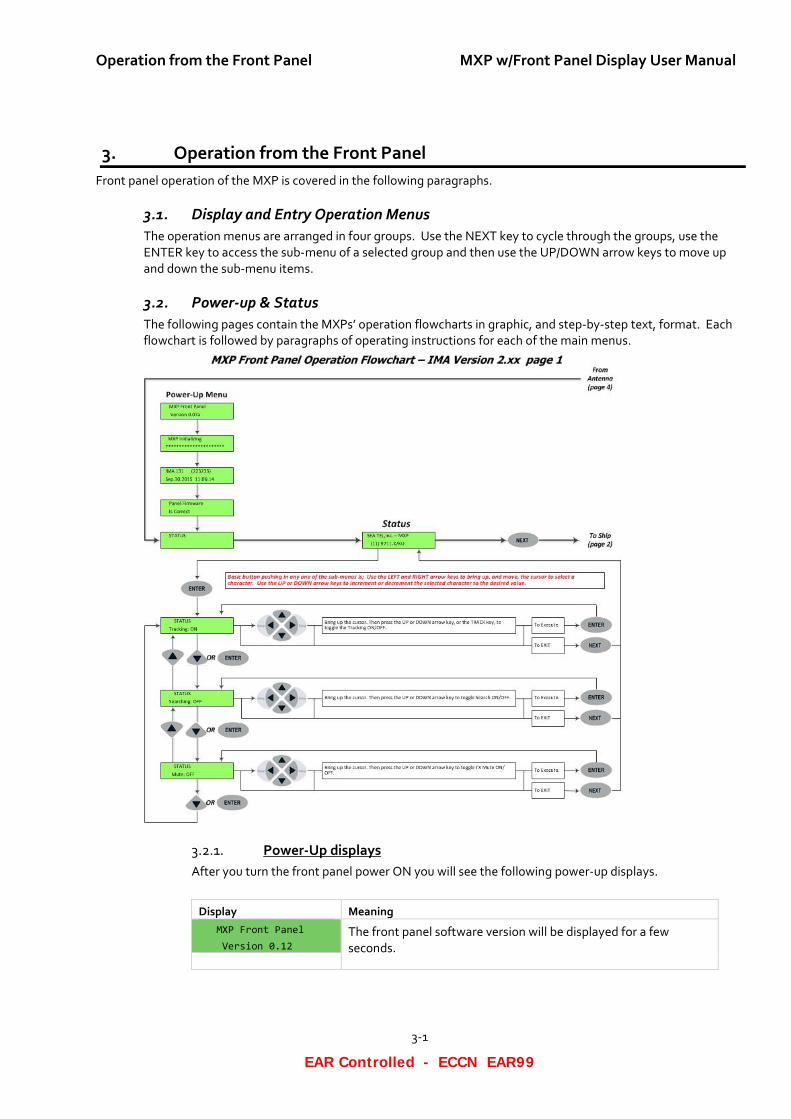
3. Operation from the Front Panel Front panel operation of the MXP is covered in the following paragraphs.
3.1. Display and Entry Operation Menus The operation menus are arranged in four groups. Use the NEXT key to cycle through the groups, use the ENTER key to access the sub-menu of a selected group and then use the UP/DOWN arrow keys to move up and down the sub-menu items.
3.2. Power-up & Status The following pages contain the MXPs’ operation flowcharts in graphic, and step-by-step text, format. Each flowchart is followed by paragraphs of operating instructions for each of the main menus.
Power-Up displays 3.2.1.After you turn the front panel power ON you will see the following power-up displays.
Display Meaning MXP Front Panel Version 0.12
The front panel software version will be displayed for a few seconds.
MXP w/Front Panel Display User Manual Operation from the Front Panel
3-2
EAR Controlled - ECCN EAR99
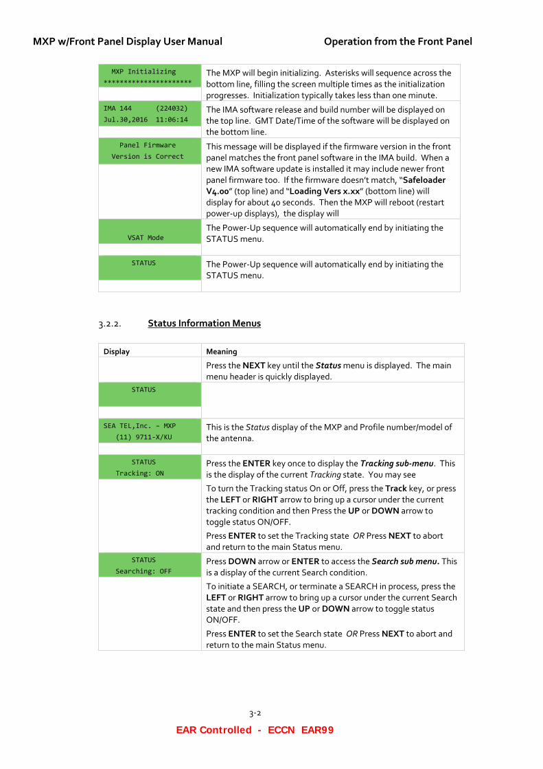
MXP Initializing **********************
The MXP will begin initializing. Asterisks will sequence across the bottom line, filling the screen multiple times as the initialization progresses. Initialization typically takes less than one minute.
IMA 144 (224032) Jul.30,2016 11:06:14
The IMA software release and build number will be displayed on the top line. GMT Date/Time of the software will be displayed on the bottom line.
Panel Firmware Version is Correct
This message will be displayed if the firmware version in the front panel matches the front panel software in the IMA build. When a new IMA software update is installed it may include newer front panel firmware too. If the firmware doesn’t match, “Safeloader V4.00” (top line) and “Loading Vers x.xx” (bottom line) will display for about 40 seconds. Then the MXP will reboot (restart power-up displays), the display will
VSAT Mode
The Power-Up sequence will automatically end by initiating the STATUS menu.
STATUS
The Power-Up sequence will automatically end by initiating the STATUS menu.
Status Information Menus 3.2.2.
Display Meaning Press the NEXT key until the Status menu is displayed. The main
menu header is quickly displayed. STATUS
SEA TEL,Inc. – MXP (11) 9711-X/KU
This is the Status display of the MXP and Profile number/model of the antenna.
STATUS Tracking: ON
Press the ENTER key once to display the Tracking sub-menu. This is the display of the current Tracking state. You may see
To turn the Tracking status On or Off, press the Track key, or press the LEFT or RIGHT arrow to bring up a cursor under the current tracking condition and then Press the UP or DOWN arrow to toggle status ON/OFF.
Press ENTER to set the Tracking state OR Press NEXT to abort and return to the main Status menu.
STATUS Searching: OFF
Press DOWN arrow or ENTER to access the Search sub menu. This is a display of the current Search condition.
To initiate a SEARCH, or terminate a SEARCH in process, press the LEFT or RIGHT arrow to bring up a cursor under the current Search state and then press the UP or DOWN arrow to toggle status ON/OFF.
Press ENTER to set the Search state OR Press NEXT to abort and return to the main Status menu.
Operation from the Front Panel MXP w/Front Panel Display User Manual
3-3
EAR Controlled - ECCN EAR99
STATUS Mute: OFF
Press DOWN arrow or ENTER to access the TX Mute sub menu. This is a display of the current TX Mute state. Turning TX Mute ON will send a TX MUTE output to the satellite modem to force it to stop transmitting. This is automatically done whenever the antenna is blocked, targeting, searching or has a stability error.
To turn the TX Mute status On or Off, press the LEFT or RIGHT arrow to bring up a cursor under the current TX Mute status and then Press the UP or DOWN arrow to toggle status ON/OFF.
Press ENTER to set the Search state OR Press NEXT to abort and return to the main Status menu.
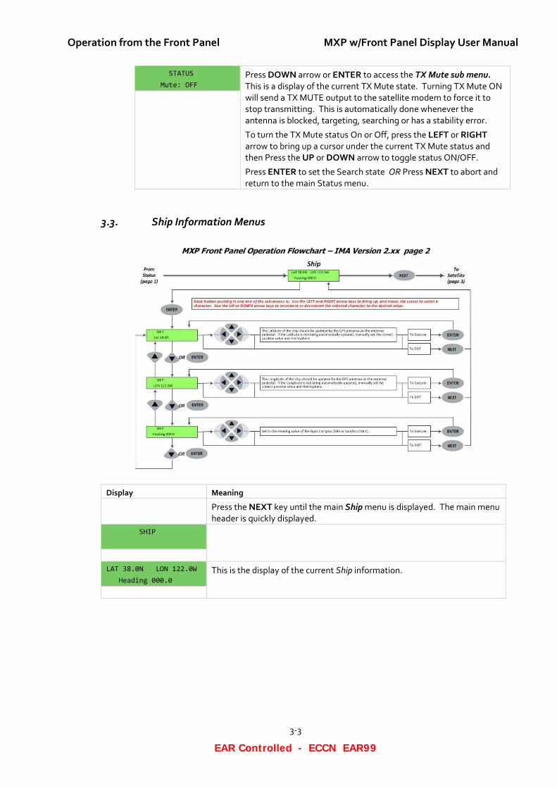
3.3. Ship Information Menus
Display Meaning Press the NEXT key until the main Ship menu is displayed. The main menu
header is quickly displayed. SHIP
LAT 38.0N LON 122.0W Heading 000.0
This is the display of the current Ship information.
MXP w/Front Panel Display User Manual Operation from the Front Panel
3-4
EAR Controlled - ECCN EAR99
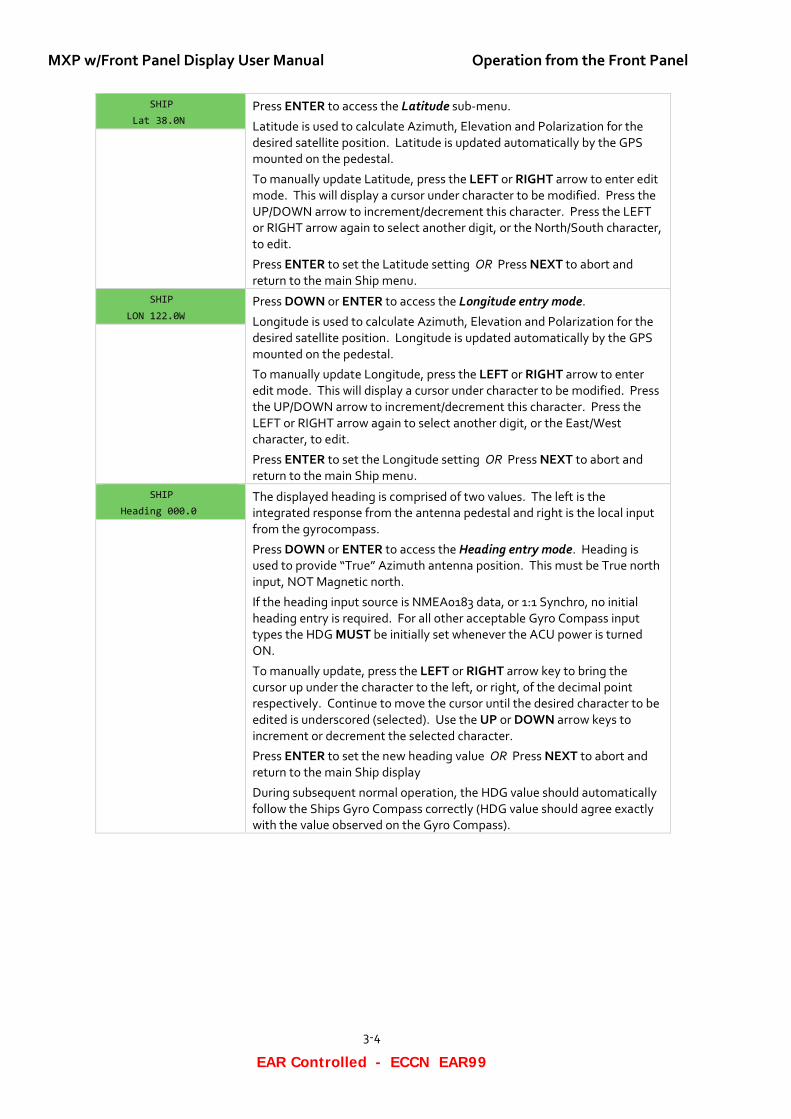
SHIP Lat 38.0N
Press ENTER to access the Latitude sub-menu.
Latitude is used to calculate Azimuth, Elevation and Polarization for the desired satellite position. Latitude is updated automatically by the GPS mounted on the pedestal.
To manually update Latitude, press the LEFT or RIGHT arrow to enter edit mode. This will display a cursor under character to be modified. Press the UP/DOWN arrow to increment/decrement this character. Press the LEFT or RIGHT arrow again to select another digit, or the North/South character, to edit.
Press ENTER to set the Latitude setting OR Press NEXT to abort and return to the main Ship menu.
SHIP LON 122.0W
Press DOWN or ENTER to access the Longitude entry mode.
Longitude is used to calculate Azimuth, Elevation and Polarization for the desired satellite position. Longitude is updated automatically by the GPS mounted on the pedestal.
To manually update Longitude, press the LEFT or RIGHT arrow to enter edit mode. This will display a cursor under character to be modified. Press the UP/DOWN arrow to increment/decrement this character. Press the LEFT or RIGHT arrow again to select another digit, or the East/West character, to edit.
Press ENTER to set the Longitude setting OR Press NEXT to abort and return to the main Ship menu.
SHIP Heading 000.0
The displayed heading is comprised of two values. The left is the integrated response from the antenna pedestal and right is the local input from the gyrocompass.
Press DOWN or ENTER to access the Heading entry mode. Heading is used to provide “True” Azimuth antenna position. This must be True north input, NOT Magnetic north.
If the heading input source is NMEA0183 data, or 1:1 Synchro, no initial heading entry is required. For all other acceptable Gyro Compass input types the HDG MUST be initially set whenever the ACU power is turned ON.
To manually update, press the LEFT or RIGHT arrow key to bring the cursor up under the character to the left, or right, of the decimal point respectively. Continue to move the cursor until the desired character to be edited is underscored (selected). Use the UP or DOWN arrow keys to increment or decrement the selected character.
Press ENTER to set the new heading value OR Press NEXT to abort and return to the main Ship display
During subsequent normal operation, the HDG value should automatically follow the Ships Gyro Compass correctly (HDG value should agree exactly with the value observed on the Gyro Compass).
Operation from the Front Panel MXP w/Front Panel Display User Manual
3-5
EAR Controlled - ECCN EAR99
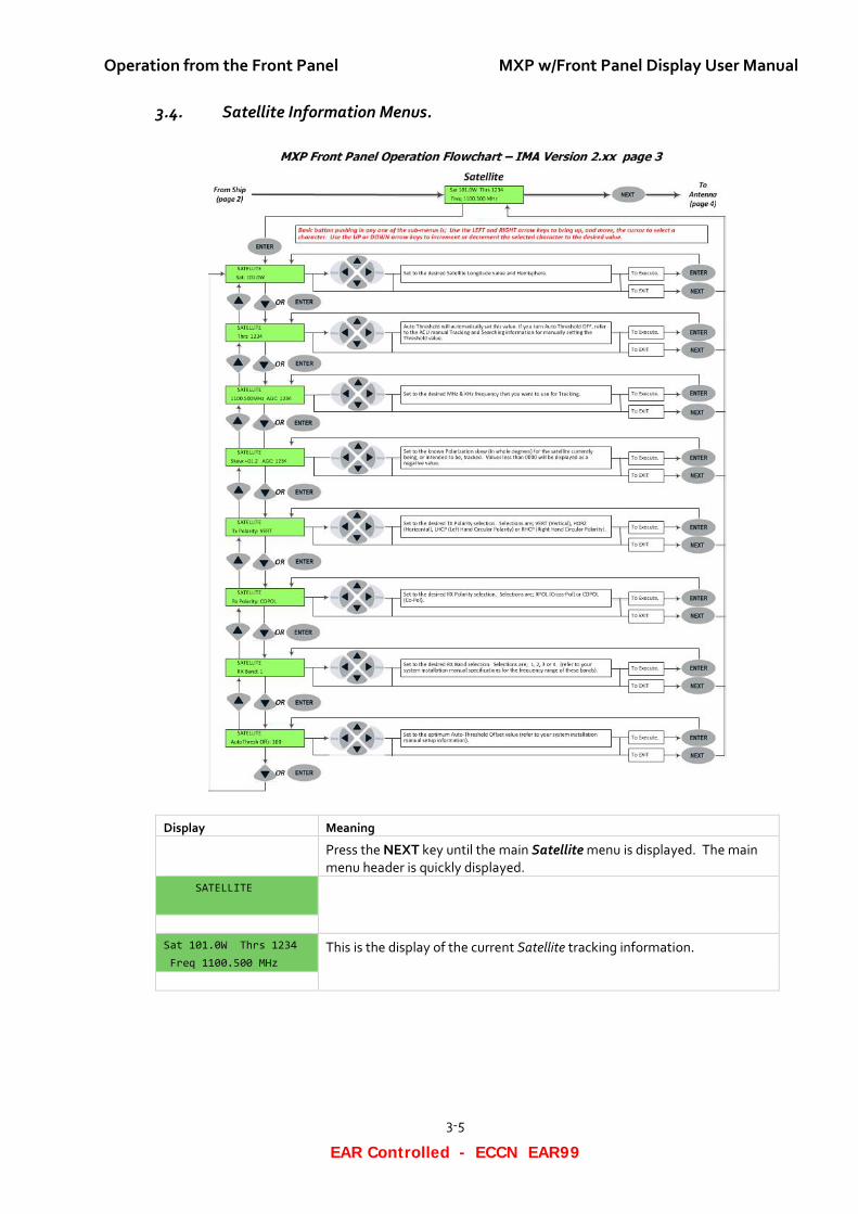
3.4. Satellite Information Menus.
Display Meaning Press the NEXT key until the main Satellite menu is displayed. The main
menu header is quickly displayed. SATELLITE
Sat 101.0W Thrs 1234 Freq 1100.500 MHz
This is the display of the current Satellite tracking information.
MXP w/Front Panel Display User Manual Operation from the Front Panel
3-6
EAR Controlled - ECCN EAR99
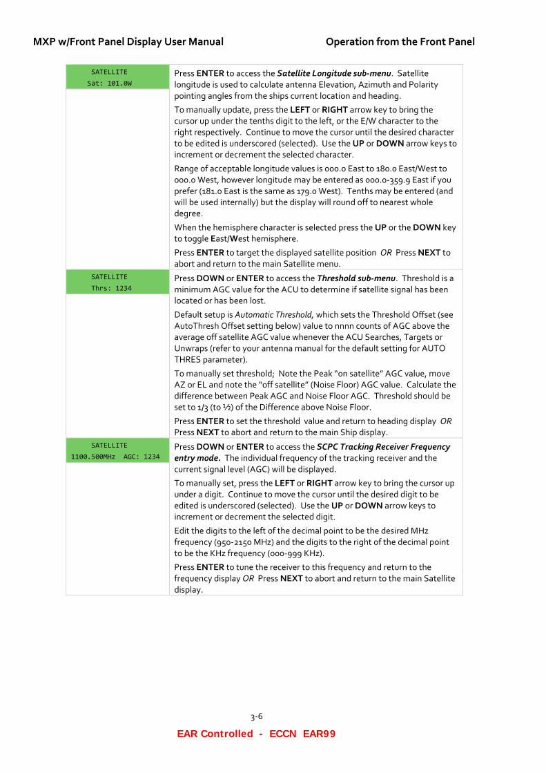
SATELLITE Sat: 101.0W
Press ENTER to access the Satellite Longitude sub-menu. Satellite longitude is used to calculate antenna Elevation, Azimuth and Polarity pointing angles from the ships current location and heading.
To manually update, press the LEFT or RIGHT arrow key to bring the cursor up under the tenths digit to the left, or the E/W character to the right respectively. Continue to move the cursor until the desired character to be edited is underscored (selected). Use the UP or DOWN arrow keys to increment or decrement the selected character.
Range of acceptable longitude values is 000.0 East to 180.0 East/West to 000.0 West, however longitude may be entered as 000.0-359.9 East if you prefer (181.0 East is the same as 179.0 West). Tenths may be entered (and will be used internally) but the display will round off to nearest whole degree.
When the hemisphere character is selected press the UP or the DOWN key to toggle East/West hemisphere.
Press ENTER to target the displayed satellite position OR Press NEXT to abort and return to the main Satellite menu.
SATELLITE Thrs: 1234
Press DOWN or ENTER to access the Threshold sub-menu. Threshold is a minimum AGC value for the ACU to determine if satellite signal has been located or has been lost.
Default setup is Automatic Threshold, which sets the Threshold Offset (see AutoThresh Offset setting below) value to nnnn counts of AGC above the average off satellite AGC value whenever the ACU Searches, Targets or Unwraps (refer to your antenna manual for the default setting for AUTO THRES parameter).
To manually set threshold; Note the Peak “on satellite” AGC value, move AZ or EL and note the “off satellite” (Noise Floor) AGC value. Calculate the difference between Peak AGC and Noise Floor AGC. Threshold should be set to 1/3 (to ½) of the Difference above Noise Floor.
Press ENTER to set the threshold value and return to heading display OR Press NEXT to abort and return to the main Ship display.
SATELLITE 1100.500MHz AGC: 1234
Press DOWN or ENTER to access the SCPC Tracking Receiver Frequency entry mode. The individual frequency of the tracking receiver and the current signal level (AGC) will be displayed.
To manually set, press the LEFT or RIGHT arrow key to bring the cursor up under a digit. Continue to move the cursor until the desired digit to be edited is underscored (selected). Use the UP or DOWN arrow keys to increment or decrement the selected digit.
Edit the digits to the left of the decimal point to be the desired MHz frequency (950-2150 MHz) and the digits to the right of the decimal point to be the KHz frequency (000-999 KHz).
Press ENTER to tune the receiver to this frequency and return to the frequency display OR Press NEXT to abort and return to the main Satellite display.
Operation from the Front Panel MXP w/Front Panel Display User Manual
3-7
EAR Controlled - ECCN EAR99
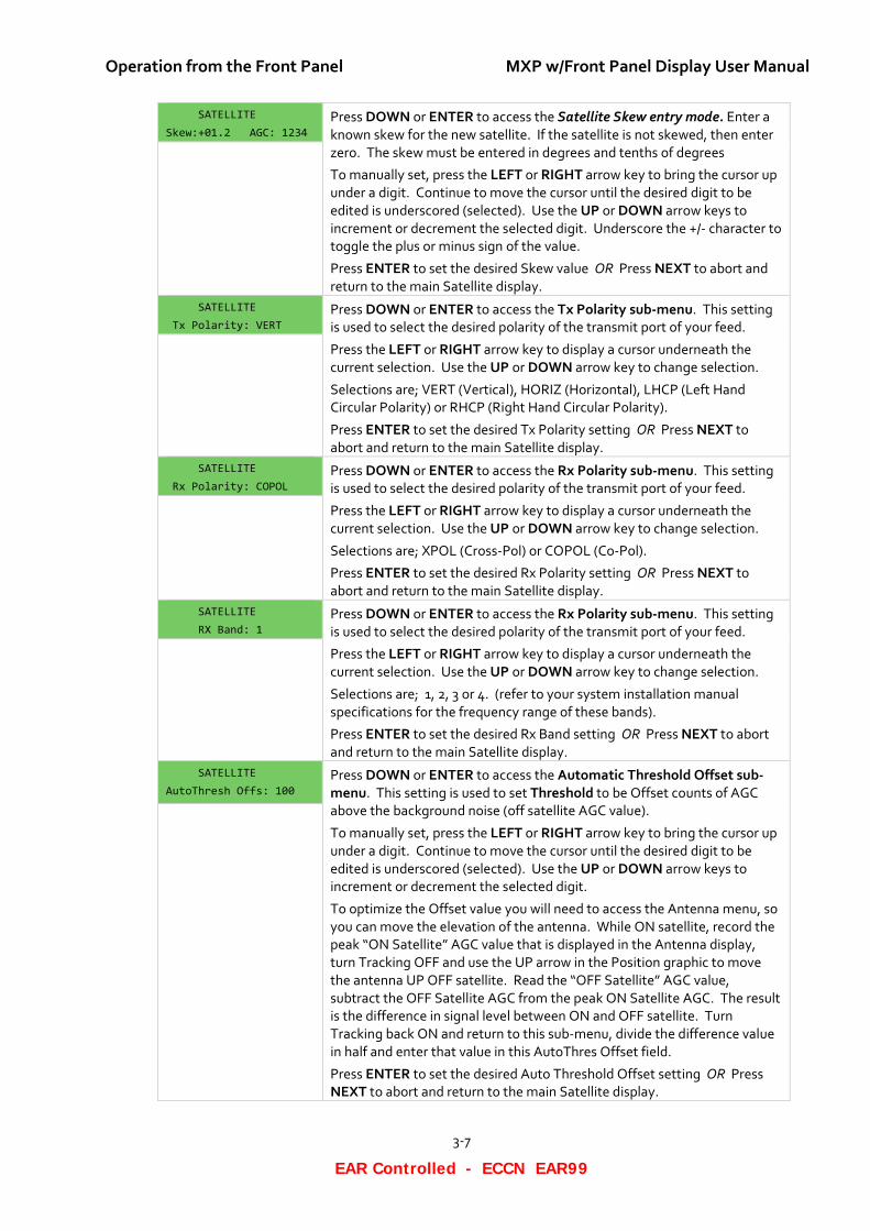
SATELLITE Skew:+01.2 AGC: 1234
Press DOWN or ENTER to access the Satellite Skew entry mode. Enter a known skew for the new satellite. If the satellite is not skewed, then enter zero. The skew must be entered in degrees and tenths of degrees
To manually set, press the LEFT or RIGHT arrow key to bring the cursor up under a digit. Continue to move the cursor until the desired digit to be edited is underscored (selected). Use the UP or DOWN arrow keys to increment or decrement the selected digit. Underscore the +/- character to toggle the plus or minus sign of the value.
Press ENTER to set the desired Skew value OR Press NEXT to abort and return to the main Satellite display.
SATELLITE Tx Polarity: VERT
Press DOWN or ENTER to access the Tx Polarity sub-menu. This setting is used to select the desired polarity of the transmit port of your feed.
Press the LEFT or RIGHT arrow key to display a cursor underneath the current selection. Use the UP or DOWN arrow key to change selection.
Selections are; VERT (Vertical), HORIZ (Horizontal), LHCP (Left Hand Circular Polarity) or RHCP (Right Hand Circular Polarity).
Press ENTER to set the desired Tx Polarity setting OR Press NEXT to abort and return to the main Satellite display.
SATELLITE Rx Polarity: COPOL
Press DOWN or ENTER to access the Rx Polarity sub-menu. This setting is used to select the desired polarity of the transmit port of your feed.
Press the LEFT or RIGHT arrow key to display a cursor underneath the current selection. Use the UP or DOWN arrow key to change selection.
Selections are; XPOL (Cross-Pol) or COPOL (Co-Pol).
Press ENTER to set the desired Rx Polarity setting OR Press NEXT to abort and return to the main Satellite display.
SATELLITE RX Band: 1
Press DOWN or ENTER to access the Rx Polarity sub-menu. This setting is used to select the desired polarity of the transmit port of your feed.
Press the LEFT or RIGHT arrow key to display a cursor underneath the current selection. Use the UP or DOWN arrow key to change selection.
Selections are; 1, 2, 3 or 4. (refer to your system installation manual specifications for the frequency range of these bands).
Press ENTER to set the desired Rx Band setting OR Press NEXT to abort and return to the main Satellite display.
SATELLITE
AutoThresh Offs: 100 Press DOWN or ENTER to access the Automatic Threshold Offset sub-menu. This setting is used to set Threshold to be Offset counts of AGC above the background noise (off satellite AGC value).
To manually set, press the LEFT or RIGHT arrow key to bring the cursor up under a digit. Continue to move the cursor until the desired digit to be edited is underscored (selected). Use the UP or DOWN arrow keys to increment or decrement the selected digit.
To optimize the Offset value you will need to access the Antenna menu, so you can move the elevation of the antenna. While ON satellite, record the peak “ON Satellite” AGC value that is displayed in the Antenna display, turn Tracking OFF and use the UP arrow in the Position graphic to move the antenna UP OFF satellite. Read the “OFF Satellite” AGC value, subtract the OFF Satellite AGC from the peak ON Satellite AGC. The result is the difference in signal level between ON and OFF satellite. Turn Tracking back ON and return to this sub-menu, divide the difference value in half and enter that value in this AutoThres Offset field.
Press ENTER to set the desired Auto Threshold Offset setting OR Press NEXT to abort and return to the main Satellite display.
MXP w/Front Panel Display User Manual Operation from the Front Panel
3-8
EAR Controlled - ECCN EAR99
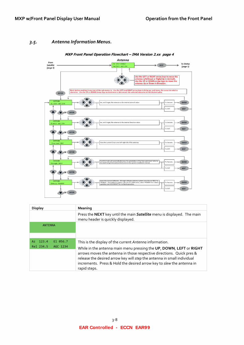
3.5. Antenna Information Menus.
Display Meaning Press the NEXT key until the main Satellite menu is displayed. The main
menu header is quickly displayed. ANTENNA
Az 123.4 El 056.7 Rel 234.5 AGC 1234
This is the display of the current Antenna information.
While in the antenna main menu pressing the UP, DOWN, LEFT or RIGHT arrows moves the antenna in those respective directions. Quick pres & release the desired arrow key will step the antenna in small individual increments. Press & Hold the desired arrow key to slew the antenna in rapid steps.
Operation from the Front Panel MXP w/Front Panel Display User Manual
3-9
EAR Controlled - ECCN EAR99
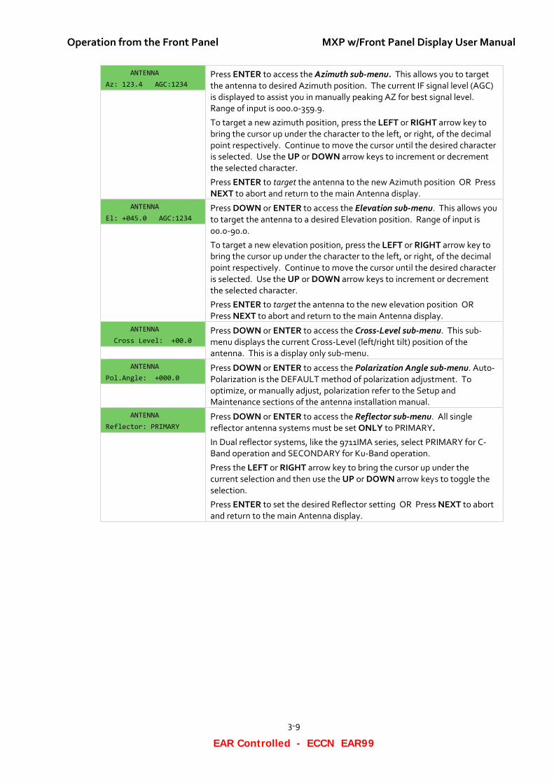
ANTENNA Az: 123.4 AGC:1234
Press ENTER to access the Azimuth sub-menu. This allows you to target the antenna to desired Azimuth position. The current IF signal level (AGC) is displayed to assist you in manually peaking AZ for best signal level. Range of input is 000.0-359.9.
To target a new azimuth position, press the LEFT or RIGHT arrow key to bring the cursor up under the character to the left, or right, of the decimal point respectively. Continue to move the cursor until the desired character is selected. Use the UP or DOWN arrow keys to increment or decrement the selected character.
Press ENTER to target the antenna to the new Azimuth position OR Press NEXT to abort and return to the main Antenna display.
ANTENNA El: +045.0 AGC:1234
Press DOWN or ENTER to access the Elevation sub-menu. This allows you to target the antenna to a desired Elevation position. Range of input is 00.0-90.0.
To target a new elevation position, press the LEFT or RIGHT arrow key to bring the cursor up under the character to the left, or right, of the decimal point respectively. Continue to move the cursor until the desired character is selected. Use the UP or DOWN arrow keys to increment or decrement the selected character.
Press ENTER to target the antenna to the new elevation position OR Press NEXT to abort and return to the main Antenna display.
ANTENNA Cross Level: +00.0
Press DOWN or ENTER to access the Cross-Level sub-menu. This sub-menu displays the current Cross-Level (left/right tilt) position of the antenna. This is a display only sub-menu.
ANTENNA Pol.Angle: +000.0
Press DOWN or ENTER to access the Polarization Angle sub-menu. Auto-Polarization is the DEFAULT method of polarization adjustment. To optimize, or manually adjust, polarization refer to the Setup and Maintenance sections of the antenna installation manual.
ANTENNA Reflector: PRIMARY
Press DOWN or ENTER to access the Reflector sub-menu. All single reflector antenna systems must be set ONLY to PRIMARY.
In Dual reflector systems, like the 9711IMA series, select PRIMARY for C-Band operation and SECONDARY for Ku-Band operation.
Press the LEFT or RIGHT arrow key to bring the cursor up under the current selection and then use the UP or DOWN arrow keys to toggle the selection.
Press ENTER to set the desired Reflector setting OR Press NEXT to abort and return to the main Antenna display.
MXP w/Front Panel Display User Manual Operation from the Front Panel
3-10
EAR Controlled - ECCN EAR99
This Page Intentionally Left Blank
Operation from the Internal Web-based GUI MXP w/Front Panel Display User Manual
4-1
EAR Controlled - ECCN EAR99
4. Operation from the Internal Web-based GUI You may prefer to operate the MXP from a computer, using the internal web-based GUI. GUI operation is covered in the following paragraphs.
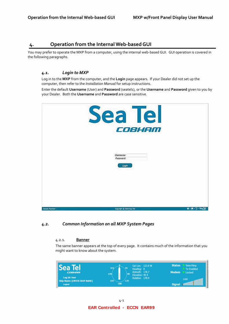
4.1. Login to MXP Log in to the MXP from the computer, and the Login page appears. If your Dealer did not set up the computer, then refer to the Installation Manual for setup instructions.
Enter the default Username (User) and Password (seatel1), or the Username and Password given to you by your Dealer. Both the Username and Password are case sensitive.
4.2. Common Information on all MXP System Pages
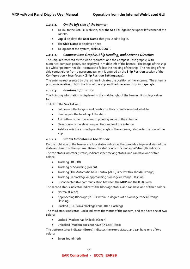
Banner 4.2.1.The same banner appears at the top of every page. It contains much of the information that you might want to know about the system.
MXP w/Front Panel Display User Manual Operation from the Internal Web-based GUI
4-2
EAR Controlled - ECCN EAR99
4.2.1.1. On the left side of the banner: • To link to the Sea Tel web site, click the Sea Tel logo in the upper-left corner of the
banner.
• Log Id displays the User Name that you used to log in.
• The Ship Name is displayed next.
• To log out of the system, click LOGOUT.
4.2.1.2. Compass Rose Graphic, Ship Heading, and Antenna Direction The Ship, represented by the white “pointer”, and the Compass Rose graphic, with numerical compass points, are displayed in middle left of the banner. The image of the ship is a white “pointer” needle. It rotates to follow the heading of the ship. The heading of the ship comes either from a gyrocompass, or it is entered on the Ship Position section of the Configuration > Interfaces > (Ship Position Setting page).
The antenna represented by the red line indicates the position of the antenna. The antenna position is relative to both the bow of the ship and the true azimuth pointing-angle.
4.2.1.3. Pointing Information The Pointing Information is displayed in the middle right of the banner. It displays values for:
To link to the Sea Tel web
• Sat Lon – is the longitudinal position of the currently selected satellite.
• Heading – is the heading of the ship.
• Azimuth — is the true azimuth pointing angle of the antenna.
• Elevation — is the elevation pointing-angle of the antenna.
• Relative — is the azimuth pointing angle of the antenna, relative to the bow of the ship.
4.2.1.1. Status Indicators in the Banner On the right side of the banner are four status indicators that provide a top-level view of the state and health of the system. Below the status indictors is a Signal Strength indicator.
The top status indicator (Status) indicates the tracking status, and can have one of five colors:
• Tracking Off (Off)
• Tracking or Searching (Green)
• Tracking (The Automatic Gain Control [AGC] is below threshold) (Orange)
• Tracking (In blockage or approaching blockage) (Orange Flashing)
• Disconnected (No communication between the MXP and the ICU) (Red)
The second status indicator indicates the blockage status, and can have one of three colors:
• Normal (Green)
• Approaching Blockage (REL is within 10 degrees of a blockage zone) (Orange Flashing)
• Blocked (REL is in a blockage zone) (Red Flashing)
The third status indicator (Lock) indicates the status of the modem, and can have one of two colors:
• Locked (Modem has RX lock) (Green)
• Unlocked (Modem does not have RX Lock) (Red)
The bottom status indicator (Errors) indicates the errors status, and can have one of two colors:
• Errors found (red)
Operation from the Internal Web-based GUI MXP w/Front Panel Display User Manual
4-3
EAR Controlled - ECCN EAR99
• No errors found (green)
If Errors are found (The Errors LED is red.), then click View to see the errors in the system. See the Troubleshooting chapter for a list of errors that can be displayed, along with other information about them. If you cannot resolve the errors, contact your Dealer for help.
4.2.1.2. Signal Level The Signal level bar graph is shown below the LEDs. It is a visual representation of the relative signal strength (AGC). The signal level is displayed, both as a digital value of AGC, and as a relative bar graph. The AGC has a range of 0 to 4095. The bar graph displays a segment of the AGC range from -300 to +300 around the orange bar. The orange bar represents the current Threshold value. Its digital value is displayed just above the graphic.
When the signal level is greater than the Threshold value, then the segments of the bar graph are green. When the signal level is less than the Threshold value, then the segments of the bar graph are red. The more green bars, the stronger the signal strength.
• If the signal strength (AGC) is 300 counts less than threshold, all bars are gray. A single gray bar represents the minimum value.
• If the signal strength (AGC) is less than the threshold, then red bars appear.
• If the signal strength (AGC) is greater than the threshold, then green bars appear.
• If the signal strength (AGC) is 300 counts greater than the threshold, then all bars are green.
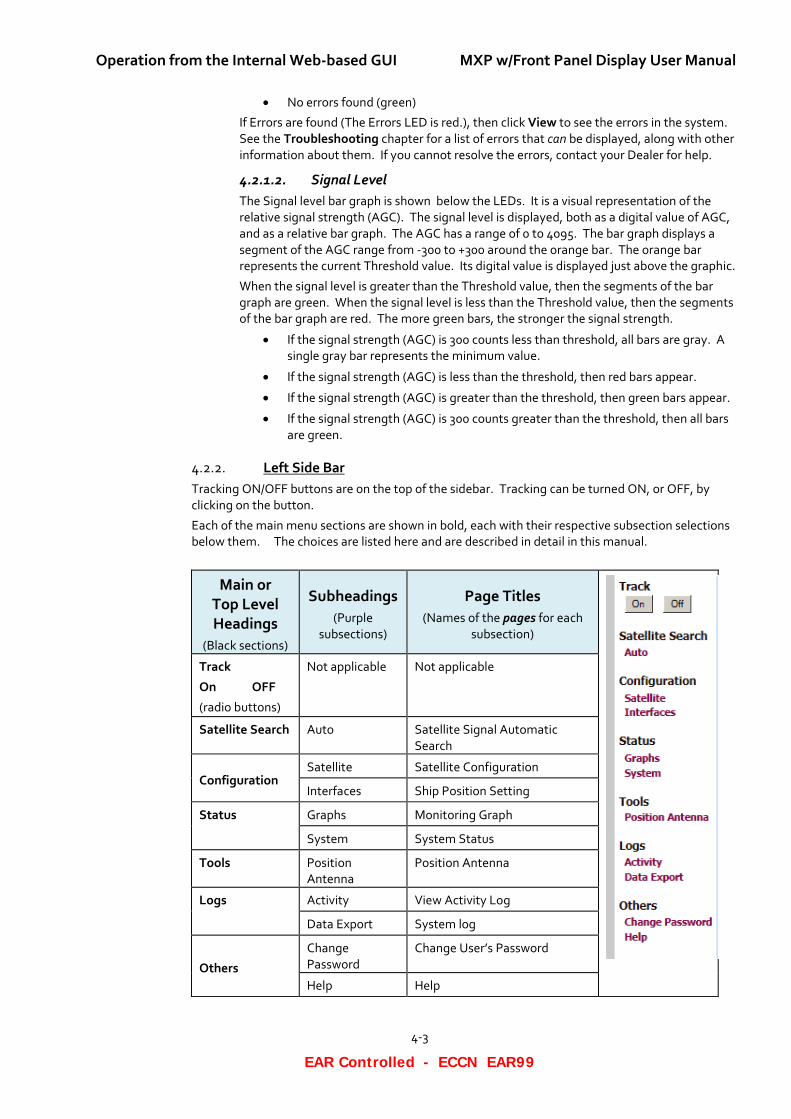
Left Side Bar 4.2.2.Tracking ON/OFF buttons are on the top of the sidebar. Tracking can be turned ON, or OFF, by clicking on the button.
Each of the main menu sections are shown in bold, each with their respective subsection selections below them. The choices are listed here and are described in detail in this manual.
Main or Top Level Headings
(Black sections)
Subheadings (Purple
subsections)
Page Titles (Names of the pages for each
subsection)
Track
On OFF
(radio buttons)
Not applicable Not applicable
Satellite Search Auto Satellite Signal Automatic Search
Configuration Satellite Satellite Configuration
Interfaces Ship Position Setting
Status Graphs Monitoring Graph
System System Status
Tools Position Antenna
Position Antenna
Logs Activity View Activity Log
Data Export System log
Others
Change Password
Change User’s Password
Help Help
MXP w/Front Panel Display User Manual Operation from the Internal Web-based GUI
4-4
EAR Controlled - ECCN EAR99
Task Bar 4.2.3.The task bar is at the bottom of each page.
The MXP Software Version and Build Number are on the left. The Copyright is in the middle.
Ignore the four icons on the right. Do not click the icons.
4.3. MXP System Pages
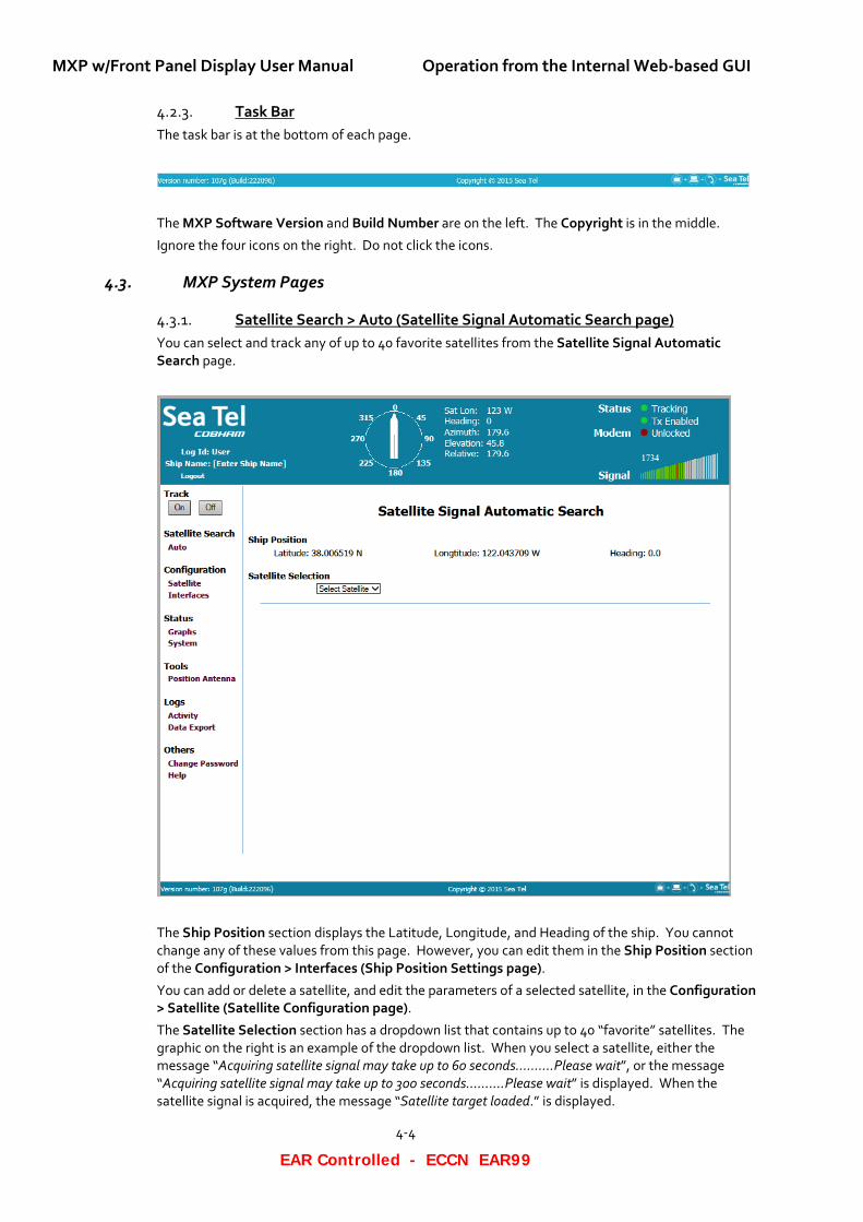
Satellite Search > Auto (Satellite Signal Automatic Search page) 4.3.1.You can select and track any of up to 40 favorite satellites from the Satellite Signal Automatic Search page.
The Ship Position section displays the Latitude, Longitude, and Heading of the ship. You cannot change any of these values from this page. However, you can edit them in the Ship Position section of the Configuration > Interfaces (Ship Position Settings page).
You can add or delete a satellite, and edit the parameters of a selected satellite, in the Configuration > Satellite (Satellite Configuration page).
The Satellite Selection section has a dropdown list that contains up to 40 “favorite” satellites. The graphic on the right is an example of the dropdown list. When you select a satellite, either the message “Acquiring satellite signal may take up to 60 seconds..........Please wait”, or the message “Acquiring satellite signal may take up to 300 seconds..........Please wait” is displayed. When the satellite signal is acquired, the message “Satellite target loaded.” is displayed.
Operation from the Internal Web-based GUI MXP w/Front Panel Display User Manual
4-5
EAR Controlled - ECCN EAR99
NOTE: If the power to the system is recycled, then after power is restored, the system retargets the last satellite that was selected.
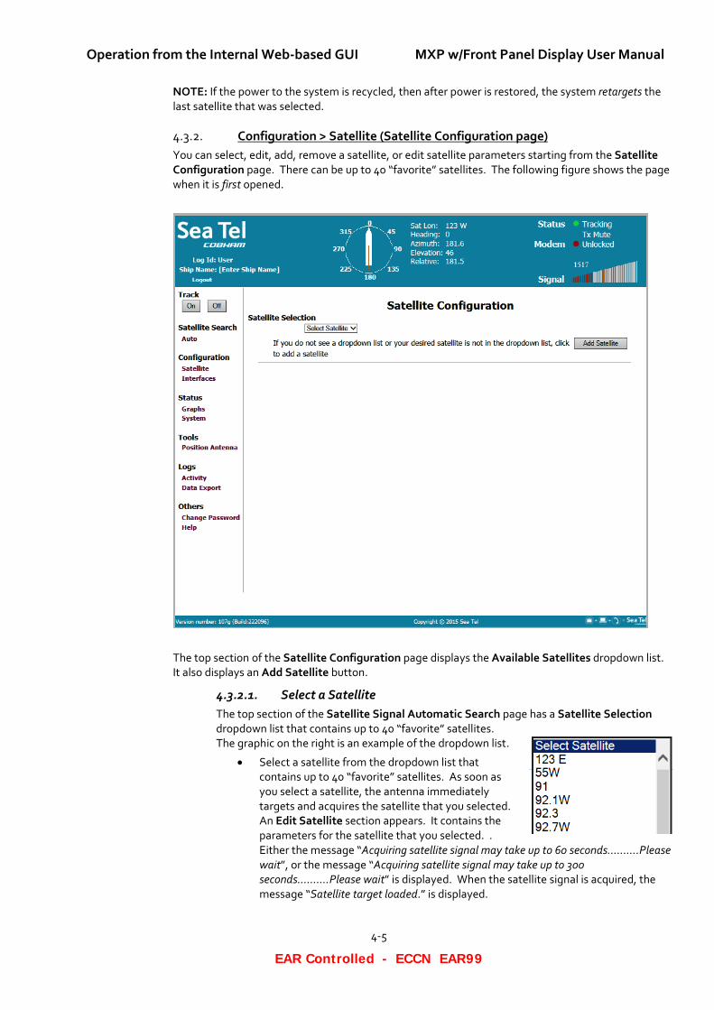
Configuration > Satellite (Satellite Configuration page) 4.3.2.You can select, edit, add, remove a satellite, or edit satellite parameters starting from the Satellite Configuration page. There can be up to 40 “favorite” satellites. The following figure shows the page when it is first opened.
The top section of the Satellite Configuration page displays the Available Satellites dropdown list. It also displays an Add Satellite button.
4.3.2.1. Select a Satellite The top section of the Satellite Signal Automatic Search page has a Satellite Selection dropdown list that contains up to 40 “favorite” satellites. The graphic on the right is an example of the dropdown list.
• Select a satellite from the dropdown list that contains up to 40 “favorite” satellites. As soon as you select a satellite, the antenna immediately targets and acquires the satellite that you selected. An Edit Satellite section appears. It contains the parameters for the satellite that you selected. . Either the message “Acquiring satellite signal may take up to 60 seconds..........Please wait”, or the message “Acquiring satellite signal may take up to 300 seconds..........Please wait” is displayed. When the satellite signal is acquired, the message “Satellite target loaded.” is displayed.
MXP w/Front Panel Display User Manual Operation from the Internal Web-based GUI
4-6
EAR Controlled - ECCN EAR99
Then the bottom section (Edit Satellite) of the Satellite Configuration page is displayed. It contains the parameters for the satellite that you selected.
NOTE: If the power to the system is recycled, then when power is restored, the system retargets the last satellite that was selected.
4.3.2.2. Remove a Satellite To remove a satellite, perform the following steps.
1. Go to the Configuration > Satellite (Satellite Configuration page).
2. From the Select Satellite dropdown list, select the satellite that you want to delete.
3. Click Remove. The satellite is removed from the Select Satellite dropdown list. The parameters and everything else about the satellite are removed from the system.
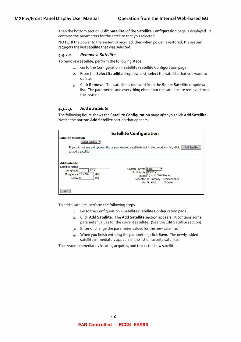
4.3.2.3. Add a Satellite The following figure shows the Satellite Configuration page after you click Add Satellite. Notice the bottom Add Satellite section that appears.
To add a satellite, perform the following steps.
1. Go to the Configuration > Satellite (Satellite Configuration page).
2. Click Add Satellite. The Add Satellite section appears. It contains some parameter values for the current satellite. (See the Edit Satellite section).
3. Enter or change the parameter values for the new satellite.
4. When you finish entering the parameters, click Save. The newly added satellite immediately appears in the list of favorite satellites.
The system immediately locates, acquires, and tracks the new satellite.
Operation from the Internal Web-based GUI MXP w/Front Panel Display User Manual
4-7
EAR Controlled - ECCN EAR99
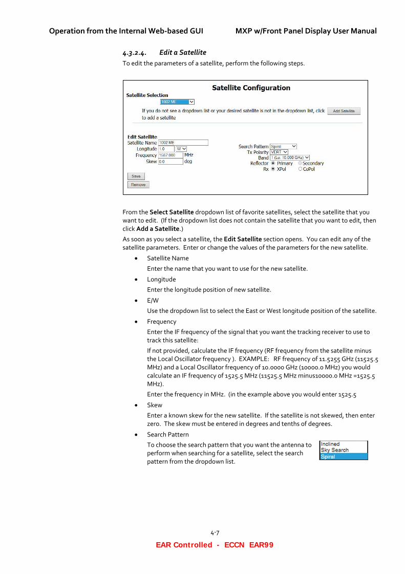
4.3.2.4. Edit a Satellite To edit the parameters of a satellite, perform the following steps.
From the Select Satellite dropdown list of favorite satellites, select the satellite that you want to edit. (If the dropdown list does not contain the satellite that you want to edit, then click Add a Satellite.)
As soon as you select a satellite, the Edit Satellite section opens. You can edit any of the satellite parameters. Enter or change the values of the parameters for the new satellite.
• Satellite Name
Enter the name that you want to use for the new satellite.
• Longitude
Enter the longitude position of new satellite.
• E/W
Use the dropdown list to select the East or West longitude position of the satellite.
• Frequency
Enter the IF frequency of the signal that you want the tracking receiver to use to track this satellite:
If not provided, calculate the IF frequency (RF frequency from the satellite minus the Local Oscillator frequency ). EXAMPLE: RF frequency of 11.5255 GHz (11525.5 MHz) and a Local Oscillator frequency of 10.0000 GHz (10000.0 MHz) you would calculate an IF frequency of 1525.5 MHz (11525.5 MHz minus10000.0 MHz =1525.5 MHz).
Enter the frequency in MHz. (in the example above you would enter 1525.5
• Skew
Enter a known skew for the new satellite. If the satellite is not skewed, then enter zero. The skew must be entered in degrees and tenths of degrees.
• Search Pattern
To choose the search pattern that you want the antenna to perform when searching for a satellite, select the search pattern from the dropdown list.
MXP w/Front Panel Display User Manual Operation from the Internal Web-based GUI
4-8
EAR Controlled - ECCN EAR99
Please note that the DEFAULT search pattern is the Spiral search.
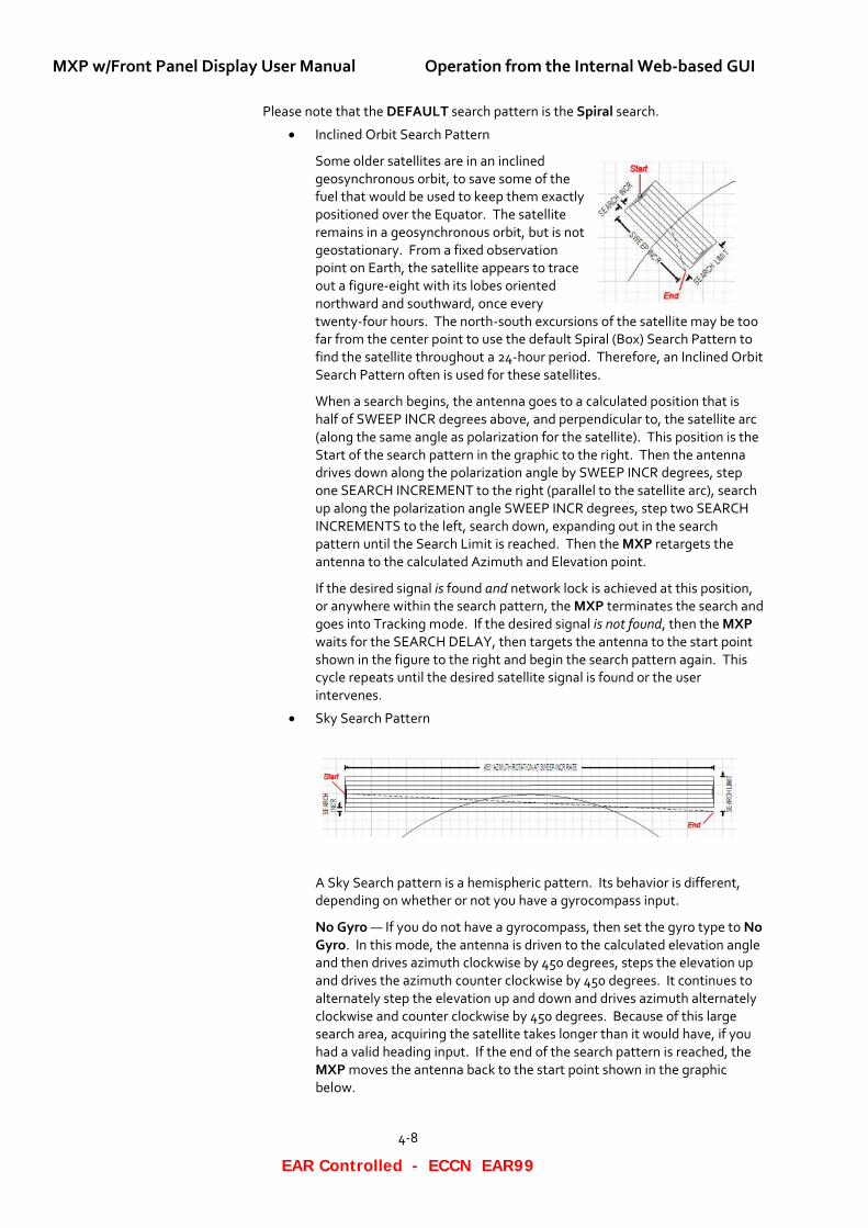
• Inclined Orbit Search Pattern
Some older satellites are in an inclined geosynchronous orbit, to save some of the fuel that would be used to keep them exactly positioned over the Equator. The satellite remains in a geosynchronous orbit, but is not geostationary. From a fixed observation point on Earth, the satellite appears to trace out a figure-eight with its lobes oriented northward and southward, once every twenty-four hours. The north-south excursions of the satellite may be too far from the center point to use the default Spiral (Box) Search Pattern to find the satellite throughout a 24-hour period. Therefore, an Inclined Orbit Search Pattern often is used for these satellites.
When a search begins, the antenna goes to a calculated position that is half of SWEEP INCR degrees above, and perpendicular to, the satellite arc (along the same angle as polarization for the satellite). This position is the Start of the search pattern in the graphic to the right. Then the antenna drives down along the polarization angle by SWEEP INCR degrees, step one SEARCH INCREMENT to the right (parallel to the satellite arc), search up along the polarization angle SWEEP INCR degrees, step two SEARCH INCREMENTS to the left, search down, expanding out in the search pattern until the Search Limit is reached. Then the MXP retargets the antenna to the calculated Azimuth and Elevation point.
If the desired signal is found and network lock is achieved at this position, or anywhere within the search pattern, the MXP terminates the search and goes into Tracking mode. If the desired signal is not found, then the MXP waits for the SEARCH DELAY, then targets the antenna to the start point shown in the figure to the right and begin the search pattern again. This cycle repeats until the desired satellite signal is found or the user intervenes.
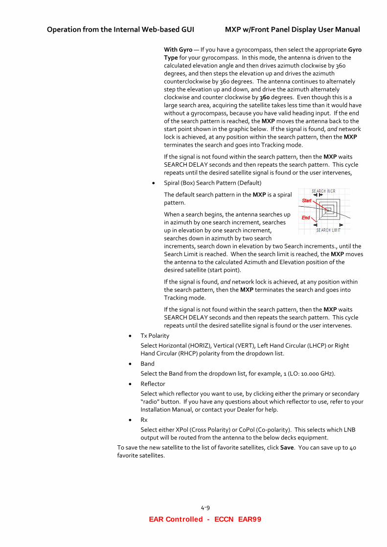
• Sky Search Pattern
A Sky Search pattern is a hemispheric pattern. Its behavior is different, depending on whether or not you have a gyrocompass input.
No Gyro — If you do not have a gyrocompass, then set the gyro type to No Gyro. In this mode, the antenna is driven to the calculated elevation angle and then drives azimuth clockwise by 450 degrees, steps the elevation up and drives the azimuth counter clockwise by 450 degrees. It continues to alternately step the elevation up and down and drives azimuth alternately clockwise and counter clockwise by 450 degrees. Because of this large search area, acquiring the satellite takes longer than it would have, if you had a valid heading input. If the end of the search pattern is reached, the MXP moves the antenna back to the start point shown in the graphic below.
Operation from the Internal Web-based GUI MXP w/Front Panel Display User Manual
4-9
EAR Controlled - ECCN EAR99
With Gyro — If you have a gyrocompass, then select the appropriate Gyro Type for your gyrocompass. In this mode, the antenna is driven to the calculated elevation angle and then drives azimuth clockwise by 360 degrees, and then steps the elevation up and drives the azimuth counterclockwise by 360 degrees. The antenna continues to alternately step the elevation up and down, and drive the azimuth alternately clockwise and counter clockwise by 360 degrees. Even though this is a large search area, acquiring the satellite takes less time than it would have without a gyrocompass, because you have valid heading input. If the end of the search pattern is reached, the MXP moves the antenna back to the start point shown in the graphic below. If the signal is found, and network lock is achieved, at any position within the search pattern, then the MXP terminates the search and goes into Tracking mode.
If the signal is not found within the search pattern, then the MXP waits SEARCH DELAY seconds and then repeats the search pattern. This cycle repeats until the desired satellite signal is found or the user intervenes,
• Spiral (Box) Search Pattern (Default)
The default search pattern in the MXP is a spiral pattern.
When a search begins, the antenna searches up in azimuth by one search increment, searches up in elevation by one search increment, searches down in azimuth by two search increments, search down in elevation by two Search increments., until the Search Limit is reached. When the search limit is reached, the MXP moves the antenna to the calculated Azimuth and Elevation position of the desired satellite (start point).
If the signal is found, and network lock is achieved, at any position within the search pattern, then the MXP terminates the search and goes into Tracking mode.
If the signal is not found within the search pattern, then the MXP waits SEARCH DELAY seconds and then repeats the search pattern. This cycle repeats until the desired satellite signal is found or the user intervenes.
• Tx Polarity
Select Horizontal (HORIZ), Vertical (VERT), Left Hand Circular (LHCP) or Right Hand Circular (RHCP) polarity from the dropdown list.
• Band
Select the Band from the dropdown list, for example, 1 (LO: 10.000 GHz).
• Reflector
Select which reflector you want to use, by clicking either the primary or secondary “radio” button. If you have any questions about which reflector to use, refer to your Installation Manual, or contact your Dealer for help.
• Rx
Select either XPol (Cross Polarity) or CoPol (Co-polarity). This selects which LNB output will be routed from the antenna to the below decks equipment.
To save the new satellite to the list of favorite satellites, click Save. You can save up to 40 favorite satellites.
MXP w/Front Panel Display User Manual Operation from the Internal Web-based GUI
4-10
EAR Controlled - ECCN EAR99
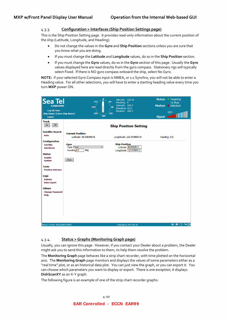
Configuration > Interfaces (Ship Position Settings page) 4.3.3.This is the Ship Position Setting page. It provides read-only information about the current position of the ship (Latitude, Longitude, and Heading).
• Do not change the values in the Gyro and Ship Position sections unless you are sure that you know what you are doing.
• If you must change the Latitude and Longitude values, do so in the Ship Position section.
• If you must change the Gyro values, do so in the Gyro section of this page. Usually the Gyro values displayed here are read directly from the gyro compass. Stationary rigs will typically select Fixed. If there is NO gyro compass onboard the ship, select No Gyro.
NOTE: if your selected Gyro Compass input is NMEA, or 1:1 Synchro, you will not be able to enter a Heading value. For all other selections, you will have to enter a starting heading value every time you turn MXP power ON.
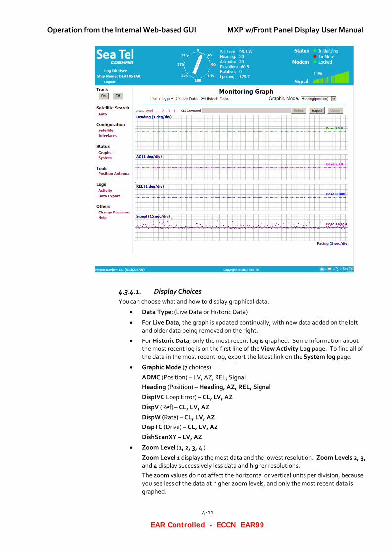
Status > Graphs (Monitoring Graph page) 4.3.4.Usually, you can ignore this page. However, if you contact your Dealer about a problem, the Dealer might ask you to send this information to them, to help them resolve the problem.
The Monitoring Graph page behaves like a strip chart recorder, with time plotted on the horizontal axis. The Monitoring Graph page monitors and displays the values of some parameters either as a “real time” plot, or as an historical data plot. You can just view the graph, or you can export it. You can choose which parameters you want to display or export. There is one exception; it displays DishScanXY as an X-Y graph.
The following figure is an example of one of the strip chart recorder graphs:
Operation from the Internal Web-based GUI MXP w/Front Panel Display User Manual
4-11
EAR Controlled - ECCN EAR99
4.3.4.1. Display Choices You can choose what and how to display graphical data.
• Data Type: (Live Data or Historic Data)
• For Live Data, the graph is updated continually, with new data added on the left and older data being removed on the right.
• For Historic Data, only the most recent log is graphed. Some information about the most recent log is on the first line of the View Activity Log page. To find all of the data in the most recent log, export the latest link on the System log page.
• Graphic Mode (7 choices)
ADMC (Position) – LV, AZ, REL, Signal
Heading (Position) – Heading, AZ, REL, Signal
DispIVC Loop Error) – CL, LV, AZ
DispV (Ref) – CL, LV, AZ
DispW (Rate) – CL, LV, AZ
DispTC (Drive) – CL, LV, AZ
DishScanXY – LV, AZ
• Zoom Level (1, 2, 3, 4 )
Zoom Level 1 displays the most data and the lowest resolution. Zoom Levels 2, 3, and 4 display successively less data and higher resolutions.
The zoom values do not affect the horizontal or vertical units per division, because you see less of the data at higher zoom levels, and only the most recent data is graphed.
MXP w/Front Panel Display User Manual Operation from the Internal Web-based GUI
4-12
EAR Controlled - ECCN EAR99
4.3.4.2. Parameter Names and Graphical Scales The parameter names are based on the chosen Graphic Mode. The horizontal and vertical units are determined by the data and whether or not the data is centered.
• The name of the parameter that is being plotted is in the top left corner of each graph. It is followed by the number of units per division (vertical scale).
• The number of time units per division (horizontal scale) is called Pacing, and it is displayed at the bottom left of the page. It is the same for all graphs on the page.
4.3.4.3. Actions You can perform the following actions on the graphical data:
• To export the graphical data as a CSV file, which you can open in a spreadsheet, click Export. Then you can either further analyze the data, or graph it in other types of graphs.
• To center the data on the Base (line), click Center. The Base is the value set when the signal of the selected parameter is at a maximum. The value if the Base follows the word Base on the right center of the graph.
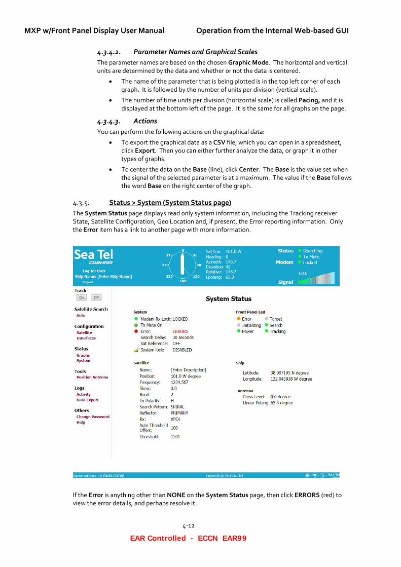
Status > System (System Status page) 4.3.5.The System Status page displays read only system information, including the Tracking receiver State, Satellite Configuration, Geo Location and, if present, the Error reporting information. Only the Error item has a link to another page with more information.
If the Error is anything other than NONE on the System Status page, then click ERRORS (red) to view the error details, and perhaps resolve it.
Operation from the Internal Web-based GUI MXP w/Front Panel Display User Manual
4-13
EAR Controlled - ECCN EAR99
4.3.5.1. System section This section is a read only display of the system states. However, for the Error status, you can click ERRORS (in red), and the Check for Errors page appears.
4.3.5.2. Satellite section This section is a read only display of the current target satellite parameters. However, for Name, you can click [Enter Description], and enter or change the name of the satellite.
4.3.5.3. Front Panel LED section This section is a mirror image of the status LEDs located on the front plate of the MXP.
4.3.5.4. Ship section This section is a read only display of the current geographic (Geo) location provided by the integrated GPS.
4.3.5.5. Antenna section This section is a read only display of the systems Cross Level and Polarization angles (degrees).
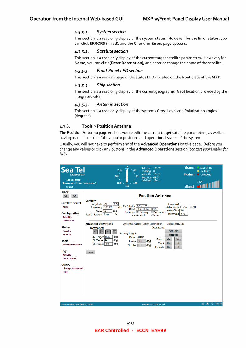
Tools > Position Antenna 4.3.6.The Position Antenna page enables you to edit the current target satellite parameters, as well as having manual control of the angular positions and operational states of the system.
Usually, you will not have to perform any of the Advanced Operations on this page. Before you change any values or click any buttons in the Advanced Operations section, contact your Dealer for help.
MXP w/Front Panel Display User Manual Operation from the Internal Web-based GUI
4-14
EAR Controlled - ECCN EAR99
4.3.6.1. Satellite Section In this section, you can enter the satellite information required by the antenna, so that it can acquire the chosen satellite.
You can edit any of the satellite parameters (see “Edit a Satellite” above).
4.3.6.2. Advanced Operations Section Usually, you will not have to perform any of the Advanced Operations on this page. Before you change any values or click any buttons in the Advanced Operations section, contact your Dealer for help.
• Antenna Name
View the Antenna Name, for example Port Antenna.
• Model
View the Model number of the system.
• Other Parameters in the Advanced Operations Section
View the rest of the parameters in the Advanced Operations section. Do not change any of these parameters unless you are absolutely sure what you are doing. You can easily damage the system if you enter the wrong parameter value. At the very least, you may cause the system to malfunction.
If you changed the values any of the parameters in the section, and you want to save them, then parameters, click Save.
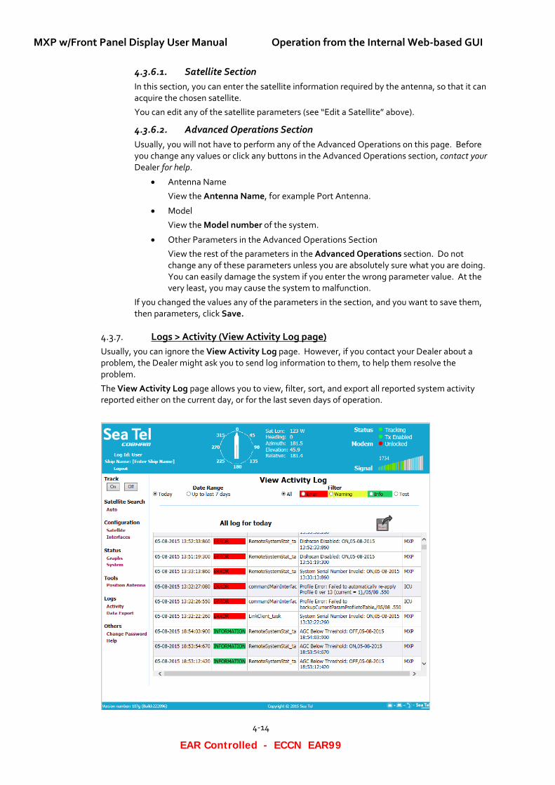
Logs > Activity (View Activity Log page) 4.3.7.Usually, you can ignore the View Activity Log page. However, if you contact your Dealer about a problem, the Dealer might ask you to send log information to them, to help them resolve the problem.
The View Activity Log page allows you to view, filter, sort, and export all reported system activity reported either on the current day, or for the last seven days of operation.
Operation from the Internal Web-based GUI MXP w/Front Panel Display User Manual
4-15
EAR Controlled - ECCN EAR99
The View Activity Log is a read only table of reported messages. You can sort them by clicking on one of the column headers (Time, Type, Status, Brief Summary, or Source).
Right-click Export (icon) to list options for exporting the desired data set to a Computer, LAN location, or USB Drive.
To view the data, execute the following steps:
1. From the left-hand bar, select Logs > Activity. The View Activity Log page appears.
2. If "no data" appears, then reboot the system. Then, click Activity and the View Activity Log should appear.
3. For Date Range, you have two choices: Today or Up to last 7 days.
4. For Filter, you have five choices: All, Error, Warning, Info, and Test.
5. Click the disc icon to export the information
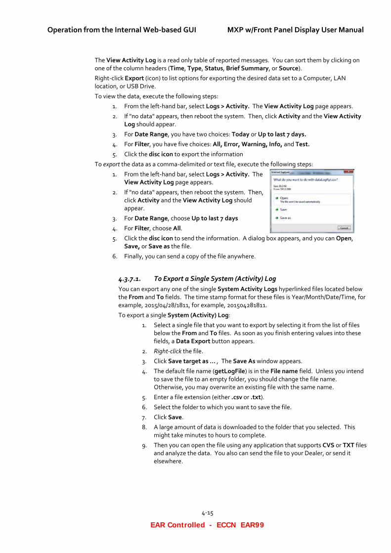
To export the data as a comma-delimited or text file, execute the following steps:
1. From the left-hand bar, select Logs > Activity. The View Activity Log page appears.
2. If "no data" appears, then reboot the system. Then, click Activity and the View Activity Log should appear.
3. For Date Range, choose Up to last 7 days
4. For Filter, choose All.
5. Click the disc icon to send the information. A dialog box appears, and you can Open, Save, or Save as the file.
6. Finally, you can send a copy of the file anywhere.
4.3.7.1. To Export a Single System (Activity) Log You can export any one of the single System Activity Logs hyperlinked files located below the From and To fields. The time stamp format for these files is Year/Month/Date/Time, for example, 2015/04/28/1811, for example, 201504281811.
To export a single System (Activity) Log:
1. Select a single file that you want to export by selecting it from the list of files below the From and To files. As soon as you finish entering values into these fields, a Data Export button appears.
2. Right-click the file.
3. Click Save target as … , The Save As window appears.
4. The default file name (getLogFile) is in the File name field. Unless you intend to save the file to an empty folder, you should change the file name. Otherwise, you may overwrite an existing file with the same name.
5. Enter a file extension (either .csv or .txt).
6. Select the folder to which you want to save the file.
7. Click Save.
8. A large amount of data is downloaded to the folder that you selected. This might take minutes to hours to complete.
9. Then you can open the file using any application that supports CVS or TXT files and analyze the data. You also can send the file to your Dealer, or send it elsewhere.
MXP w/Front Panel Display User Manual Operation from the Internal Web-based GUI
4-16
EAR Controlled - ECCN EAR99
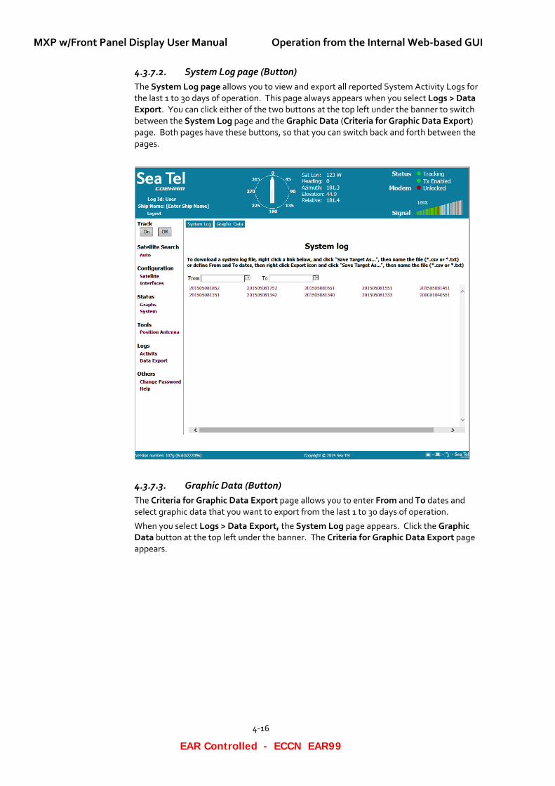
4.3.7.2. System Log page (Button) The System Log page allows you to view and export all reported System Activity Logs for the last 1 to 30 days of operation. This page always appears when you select Logs > Data Export. You can click either of the two buttons at the top left under the banner to switch between the System Log page and the Graphic Data (Criteria for Graphic Data Export) page. Both pages have these buttons, so that you can switch back and forth between the pages.
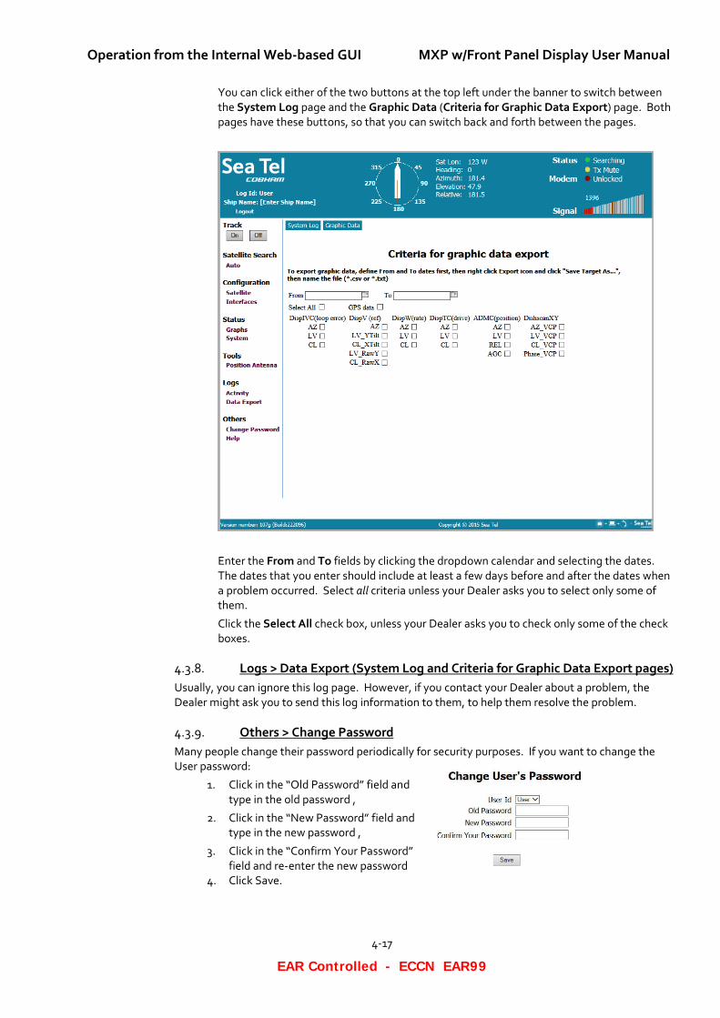
4.3.7.3. Graphic Data (Button) The Criteria for Graphic Data Export page allows you to enter From and To dates and select graphic data that you want to export from the last 1 to 30 days of operation.
When you select Logs > Data Export, the System Log page appears. Click the Graphic Data button at the top left under the banner. The Criteria for Graphic Data Export page appears.
Operation from the Internal Web-based GUI MXP w/Front Panel Display User Manual
4-17
EAR Controlled - ECCN EAR99
You can click either of the two buttons at the top left under the banner to switch between the System Log page and the Graphic Data (Criteria for Graphic Data Export) page. Both pages have these buttons, so that you can switch back and forth between the pages.
Enter the From and To fields by clicking the dropdown calendar and selecting the dates. The dates that you enter should include at least a few days before and after the dates when a problem occurred. Select all criteria unless your Dealer asks you to select only some of them.
Click the Select All check box, unless your Dealer asks you to check only some of the check boxes.
Logs > Data Export (System Log and Criteria for Graphic Data Export pages) 4.3.8.Usually, you can ignore this log page. However, if you contact your Dealer about a problem, the Dealer might ask you to send this log information to them, to help them resolve the problem.
Others > Change Password 4.3.9.Many people change their password periodically for security purposes. If you want to change the User password:
1. Click in the “Old Password” field and type in the old password ,
2. Click in the “New Password” field and type in the new password ,
3. Click in the “Confirm Your Password” field and re-enter the new password
4. Click Save.
MXP w/Front Panel Display User Manual Operation from the Internal Web-based GUI
4-18
EAR Controlled - ECCN EAR99
Cyber Security Caution 4.3.10.Sea Tel Antenna systems are not intended to be connected directly to the Internet. They must be connected behind a dedicated network security device such as a firewall. In addition, we highly recommended that you change default passwords. This is an extremely important consideration that must be taken into account as part of commissioning procedures as attackers with malicious intent (after easily obtaining default passwords and identify internet-connected systems) can be rendered a system inoperable.
For clarification purposes, the factory default Passwords/Configurations are only intended for initial production testing/verification purposes and it is an assumed responsibility of the installing partner to change and record the login credentials and is shared only with persons whom are directly responsible for operation/maintenance of the system. Instructions on how to change passwords may be located within the system manual.
Others > Help (Help / FAQ page) 4.3.11.This page has two selection buttons at the top of the page. Select one of them to display, either Help, or FAQ.
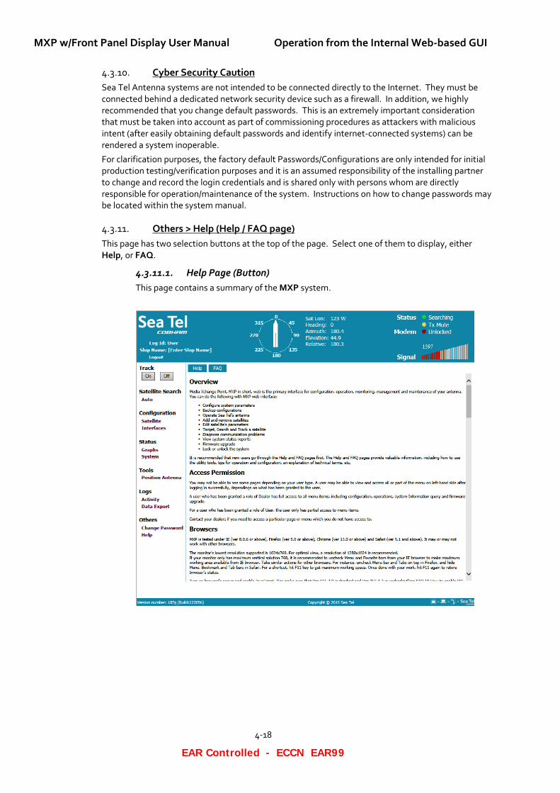
4.3.11.1. Help Page (Button) This page contains a summary of the MXP system.
Operation from the Internal Web-based GUI MXP w/Front Panel Display User Manual
4-19
EAR Controlled - ECCN EAR99
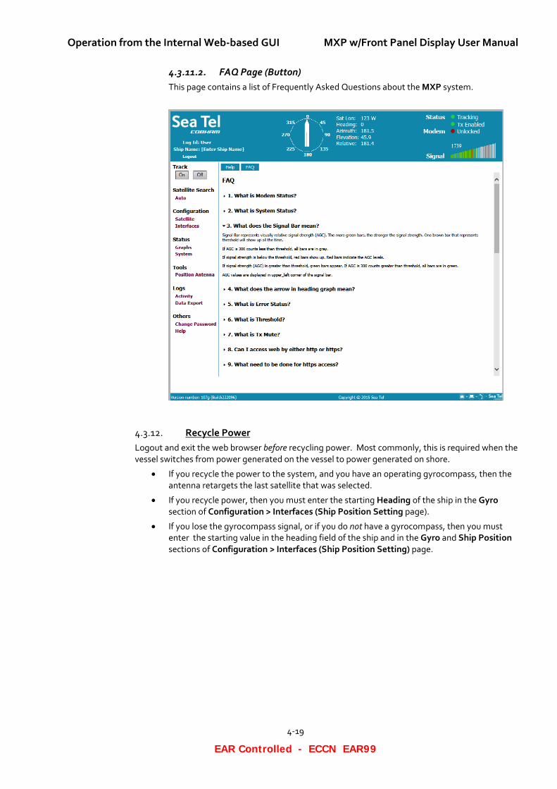
4.3.11.2. FAQ Page (Button) This page contains a list of Frequently Asked Questions about the MXP system.
Recycle Power 4.3.12.Logout and exit the web browser before recycling power. Most commonly, this is required when the vessel switches from power generated on the vessel to power generated on shore.
• If you recycle the power to the system, and you have an operating gyrocompass, then the antenna retargets the last satellite that was selected.
• If you recycle power, then you must enter the starting Heading of the ship in the Gyro section of Configuration > Interfaces (Ship Position Setting page).
• If you lose the gyrocompass signal, or if you do not have a gyrocompass, then you must enter the starting value in the heading field of the ship and in the Gyro and Ship Position sections of Configuration > Interfaces (Ship Position Setting) page.
MXP w/Front Panel Display User Manual Operation from the Internal Web-based GUI
4-20
EAR Controlled - ECCN EAR99
This Page Intentionally Left Blank
Setup from the Front Panel MXP w/Front Panel Display User Manual
5-1
EAR Controlled - ECCN EAR99
5. Setup from the Front Panel The display panel allows you to access the Setup parameters of the MXP if the front panel has not been locked. If you front panel has been locked, you will be able to display the Setup parameters but not change them.
Follow the instructions below to display/edit the Setup Parameters of your MXP.
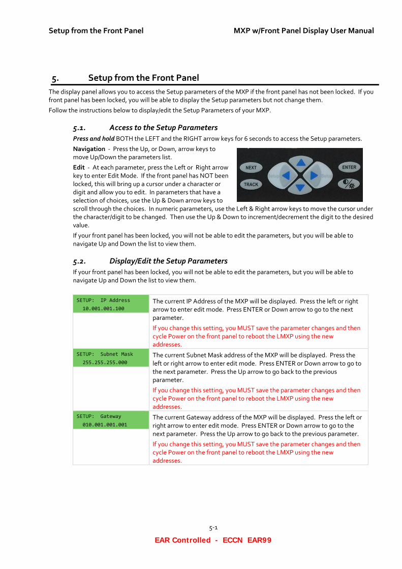
5.1. Access to the Setup Parameters Press and hold BOTH the LEFT and the RIGHT arrow keys for 6 seconds to access the Setup parameters.
Navigation - Press the Up, or Down, arrow keys to move Up/Down the parameters list.
Edit - At each parameter, press the Left or Right arrow key to enter Edit Mode. If the front panel has NOT been locked, this will bring up a cursor under a character or digit and allow you to edit. In parameters that have a selection of choices, use the Up & Down arrow keys to scroll through the choices. In numeric parameters, use the Left & Right arrow keys to move the cursor under the character/digit to be changed. Then use the Up & Down to increment/decrement the digit to the desired value.
If your front panel has been locked, you will not be able to edit the parameters, but you will be able to navigate Up and Down the list to view them.
5.2. Display/Edit the Setup Parameters If your front panel has been locked, you will not be able to edit the parameters, but you will be able to navigate Up and Down the list to view them.
SETUP: IP Address 10.001.001.100
The current IP Address of the MXP will be displayed. Press the left or right arrow to enter edit mode. Press ENTER or Down arrow to go to the next parameter.
If you change this setting, you MUST save the parameter changes and then cycle Power on the front panel to reboot the LMXP using the new addresses.
SETUP: Subnet Mask 255.255.255.000
The current Subnet Mask address of the MXP will be displayed. Press the left or right arrow to enter edit mode. Press ENTER or Down arrow to go to the next parameter. Press the Up arrow to go back to the previous parameter.
If you change this setting, you MUST save the parameter changes and then cycle Power on the front panel to reboot the LMXP using the new addresses.
SETUP: Gateway 010.001.001.001
The current Gateway address of the MXP will be displayed. Press the left or right arrow to enter edit mode. Press ENTER or Down arrow to go to the next parameter. Press the Up arrow to go back to the previous parameter.
If you change this setting, you MUST save the parameter changes and then cycle Power on the front panel to reboot the LMXP using the new addresses.
MXP w/Front Panel Display User Manual Setup from the Front Panel
5-2
EAR Controlled - ECCN EAR99
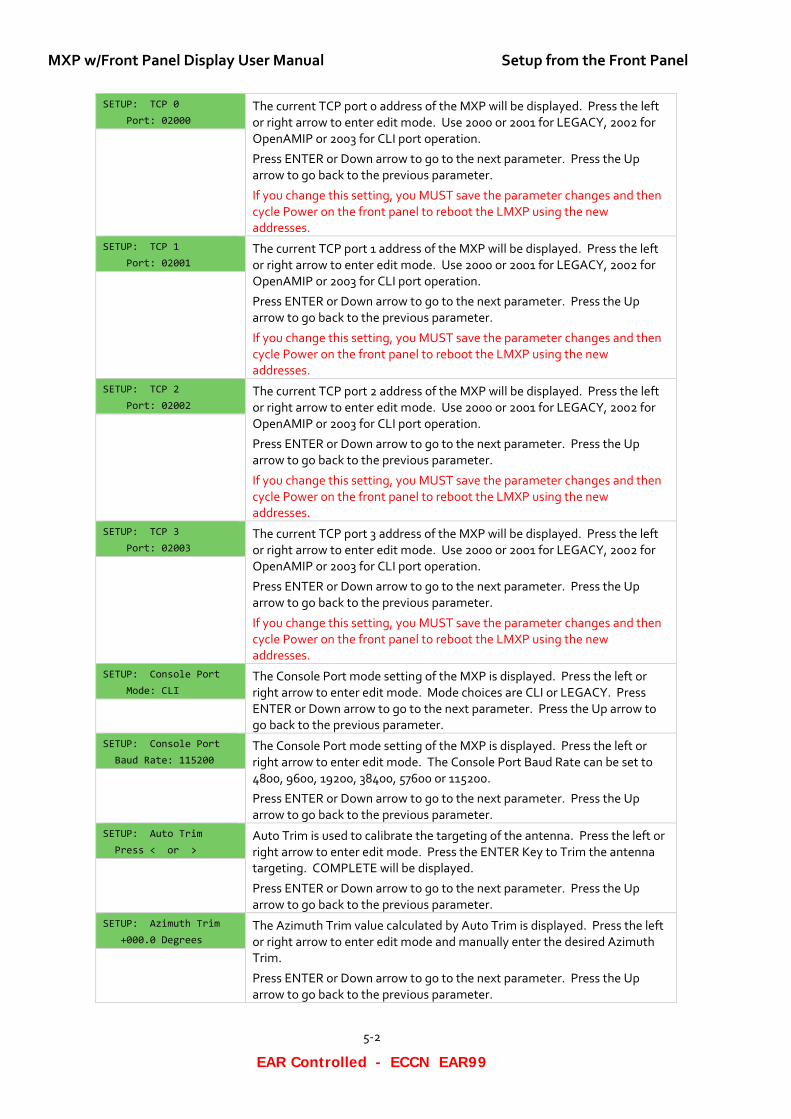
SETUP: TCP 0 Port: 02000
The current TCP port 0 address of the MXP will be displayed. Press the left or right arrow to enter edit mode. Use 2000 or 2001 for LEGACY, 2002 for OpenAMIP or 2003 for CLI port operation.
Press ENTER or Down arrow to go to the next parameter. Press the Up arrow to go back to the previous parameter.
If you change this setting, you MUST save the parameter changes and then cycle Power on the front panel to reboot the LMXP using the new addresses.
SETUP: TCP 1 Port: 02001
The current TCP port 1 address of the MXP will be displayed. Press the left or right arrow to enter edit mode. Use 2000 or 2001 for LEGACY, 2002 for OpenAMIP or 2003 for CLI port operation.
Press ENTER or Down arrow to go to the next parameter. Press the Up arrow to go back to the previous parameter.
If you change this setting, you MUST save the parameter changes and then cycle Power on the front panel to reboot the LMXP using the new addresses.
SETUP: TCP 2 Port: 02002
The current TCP port 2 address of the MXP will be displayed. Press the left or right arrow to enter edit mode. Use 2000 or 2001 for LEGACY, 2002 for OpenAMIP or 2003 for CLI port operation.
Press ENTER or Down arrow to go to the next parameter. Press the Up arrow to go back to the previous parameter.
If you change this setting, you MUST save the parameter changes and then cycle Power on the front panel to reboot the LMXP using the new addresses.
SETUP: TCP 3 Port: 02003
The current TCP port 3 address of the MXP will be displayed. Press the left or right arrow to enter edit mode. Use 2000 or 2001 for LEGACY, 2002 for OpenAMIP or 2003 for CLI port operation.
Press ENTER or Down arrow to go to the next parameter. Press the Up arrow to go back to the previous parameter.
If you change this setting, you MUST save the parameter changes and then cycle Power on the front panel to reboot the LMXP using the new addresses.
SETUP: Console Port Mode: CLI
The Console Port mode setting of the MXP is displayed. Press the left or right arrow to enter edit mode. Mode choices are CLI or LEGACY. Press ENTER or Down arrow to go to the next parameter. Press the Up arrow to go back to the previous parameter.
SETUP: Console Port Baud Rate: 115200
The Console Port mode setting of the MXP is displayed. Press the left or right arrow to enter edit mode. The Console Port Baud Rate can be set to 4800, 9600, 19200, 38400, 57600 or 115200.
Press ENTER or Down arrow to go to the next parameter. Press the Up arrow to go back to the previous parameter.
SETUP: Auto Trim Press < or >
Auto Trim is used to calibrate the targeting of the antenna. Press the left or right arrow to enter edit mode. Press the ENTER Key to Trim the antenna targeting. COMPLETE will be displayed.
Press ENTER or Down arrow to go to the next parameter. Press the Up arrow to go back to the previous parameter.
SETUP: Azimuth Trim +000.0 Degrees
The Azimuth Trim value calculated by Auto Trim is displayed. Press the left or right arrow to enter edit mode and manually enter the desired Azimuth Trim.
Press ENTER or Down arrow to go to the next parameter. Press the Up arrow to go back to the previous parameter.
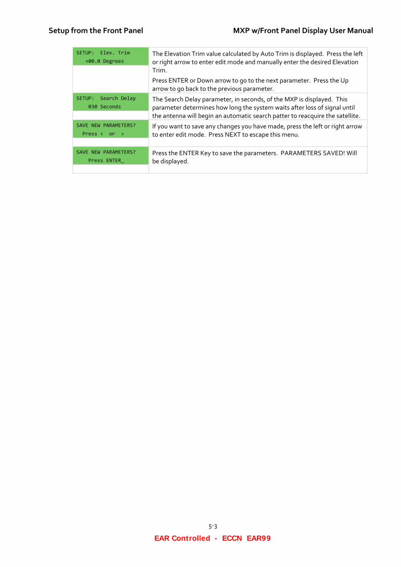
Setup from the Front Panel MXP w/Front Panel Display User Manual
5-3
EAR Controlled - ECCN EAR99
SETUP: Elev. Trim +00.0 Degrees
The Elevation Trim value calculated by Auto Trim is displayed. Press the left or right arrow to enter edit mode and manually enter the desired Elevation Trim.
Press ENTER or Down arrow to go to the next parameter. Press the Up arrow to go back to the previous parameter.
SETUP: Search Delay 030 Seconds
The Search Delay parameter, in seconds, of the MXP is displayed. This parameter determines how long the system waits after loss of signal until the antenna will begin an automatic search patter to reacquire the satellite.
SAVE NEW PARAMETERS? Press < or >
If you want to save any changes you have made, press the left or right arrow to enter edit mode. Press NEXT to escape this menu.
SAVE NEW PARAMETERS? Press ENTER_
Press the ENTER Key to save the parameters. PARAMETERS SAVED! Will be displayed.

MXP w/Front Panel Display User Manual Setup from the Front Panel
5-4
EAR Controlled - ECCN EAR99
This Page Intentionally Left Blank
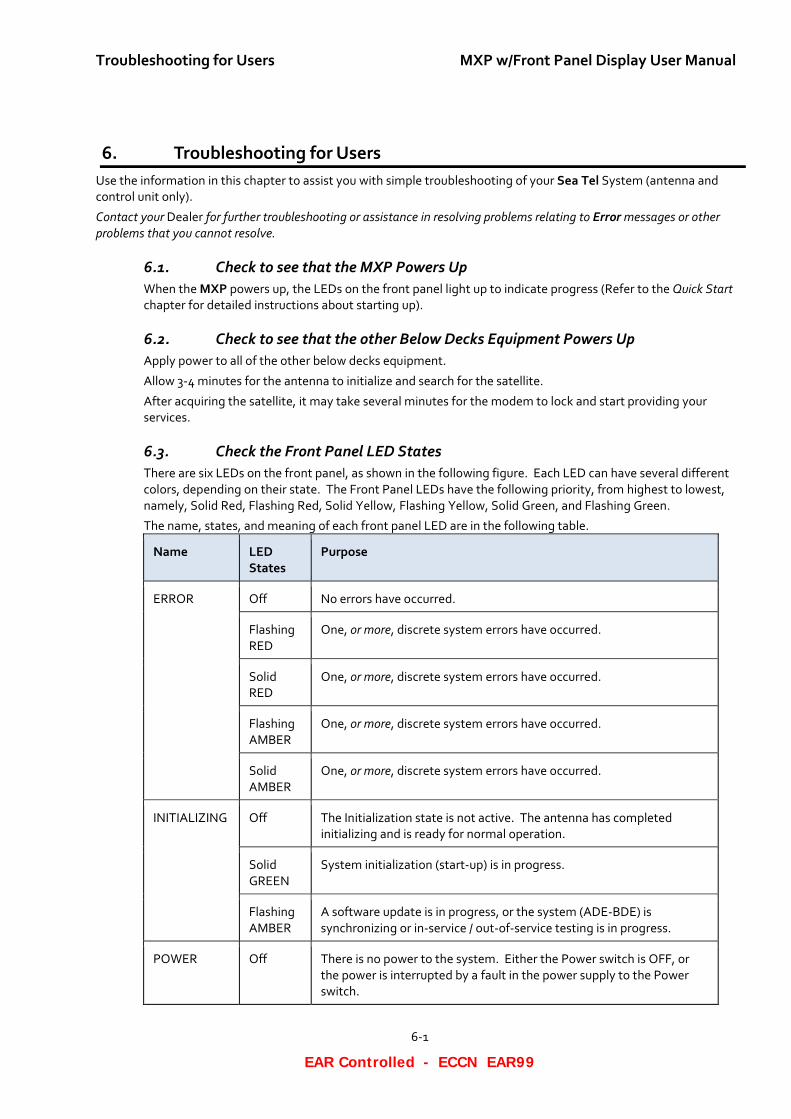
Troubleshooting for Users MXP w/Front Panel Display User Manual
6-1
EAR Controlled - ECCN EAR99
6. Troubleshooting for Users Use the information in this chapter to assist you with simple troubleshooting of your Sea Tel System (antenna and control unit only).
Contact your Dealer for further troubleshooting or assistance in resolving problems relating to Error messages or other problems that you cannot resolve.
6.1. Check to see that the MXP Powers Up When the MXP powers up, the LEDs on the front panel light up to indicate progress (Refer to the Quick Start chapter for detailed instructions about starting up).
6.2. Check to see that the other Below Decks Equipment Powers Up Apply power to all of the other below decks equipment.
Allow 3-4 minutes for the antenna to initialize and search for the satellite.
After acquiring the satellite, it may take several minutes for the modem to lock and start providing your services.
6.3. Check the Front Panel LED States There are six LEDs on the front panel, as shown in the following figure. Each LED can have several different colors, depending on their state. The Front Panel LEDs have the following priority, from highest to lowest, namely, Solid Red, Flashing Red, Solid Yellow, Flashing Yellow, Solid Green, and Flashing Green.
The name, states, and meaning of each front panel LED are in the following table.
Name LED States
Purpose
ERROR Off No errors have occurred.
Flashing RED
One, or more, discrete system errors have occurred.
Solid RED
One, or more, discrete system errors have occurred.
Flashing AMBER
One, or more, discrete system errors have occurred.
Solid AMBER
One, or more, discrete system errors have occurred.
INITIALIZING Off The Initialization state is not active. The antenna has completed initializing and is ready for normal operation.
Solid GREEN
System initialization (start-up) is in progress.
Flashing AMBER
A software update is in progress, or the system (ADE-BDE) is synchronizing or in-service / out-of-service testing is in progress.
POWER Off There is no power to the system. Either the Power switch is OFF, or the power is interrupted by a fault in the power supply to the Power switch.
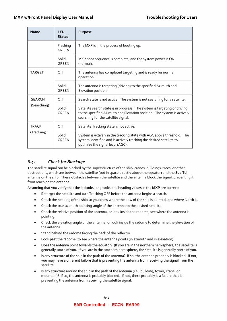
MXP w/Front Panel Display User Manual Troubleshooting for Users
6-2
EAR Controlled - ECCN EAR99
Name LED States
Purpose
Flashing GREEN
The MXP is in the process of booting up.
Solid GREEN
MXP boot sequence is complete, and the system power is ON (normal).
TARGET Off The antenna has completed targeting and is ready for normal operation.
Solid GREEN
The antenna is targeting (driving) to the specified Azimuth and Elevation position.
SEARCH
(Searching)
Off Search state is not active. The system is not searching for a satellite.
Solid GREEN
Satellite search state is in progress. The system is targeting or driving to the specified Azimuth and Elevation position. The system is actively searching for the satellite signal.
TRACK
(Tracking)
Off Satellite Tracking state is not active.
Solid GREEN
System is actively in the tracking state with AGC above threshold. The system identified and is actively tracking the desired satellite to optimize the signal level (AGC).
6.4. Check for Blockage The satellite signal can be blocked by the superstructure of the ship, cranes, buildings, trees, or other obstructions, which are between the satellite (out in space directly above the equator) and the Sea Tel antenna on the ship. These obstacles between the satellite and the antenna block the signal, preventing it from reaching the antenna.
Assuming that you verify that the latitude, longitude, and heading values in the MXP are correct:
• Retarget the satellite and turn Tracking OFF before the antenna begins a search.
• Check the heading of the ship so you know where the bow of the ship is pointed, and where North is.
• Check the true azimuth pointing-angle of the antenna to the desired satellite.
• Check the relative position of the antenna, or look inside the radome, see where the antenna is pointing.
• Check the elevation angle of the antenna, or look inside the radome to determine the elevation of the antenna.
• Stand behind the radome facing the back of the reflector.
• Look past the radome, to see where the antenna points (in azimuth and in elevation).
• Does the antenna point towards the equator? (If you are in the northern hemisphere, the satellite is generally south of you. If you are in the southern hemisphere, the satellite is generally north of you.
• Is any structure of the ship in the path of the antenna? If so, the antenna probably is blocked. If not, you may have a different failure that is preventing the antenna from receiving the signal from the satellite.
• Is any structure around the ship in the path of the antenna (i.e., building, tower, crane, or mountain)? If so, the antenna is probably blocked. If not, there probably is a failure that is preventing the antenna from receiving the satellite signal.
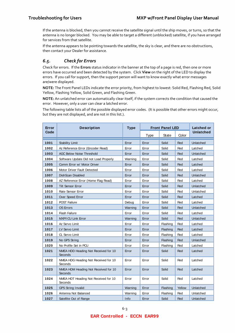
Troubleshooting for Users MXP w/Front Panel Display User Manual
6-3
EAR Controlled - ECCN EAR99
If the antenna is blocked, then you cannot receive the satellite signal until the ship moves, or turns, so that the antenna is no longer blocked. You may be able to target a different (unblocked) satellite, if you have arranged for services from that satellite.
If the antenna appears to be pointing towards the satellite, the sky is clear, and there are no obstructions, then contact your Dealer for assistance.
6.5. Check for Errors Check for errors. If the Errors status indicator in the banner at the top of a page is red, then one or more errors have occurred and been detected by the system. Click View on the right of the LED to display the errors. If you call for support, then the support person will want to know exactly what error messages are/were displayed.
NOTE: The Front Panel LEDs indicate the error priority, from highest to lowest: Solid Red, Flashing Red, Solid Yellow, Flashing Yellow, Solid Green, and Flashing Green.
NOTE: An unlatched error can automatically clear itself, if the system corrects the condition that caused the error. However, only a user can clear a latched error.
The following table lists all of the possible displayed error codes. (It is possible that other errors might occur, but they are not displayed, and are not in this list.).
Error Code
Description Type Front Panel LED Latched or Unlatched
Type State Color
1001 Stability Limit Error Error Solid Red Unlatched
1002 Az Reference Error (Encoder Read) Error Error Solid Red Latched
1003 AGC Below Noise Threshold Error Error Solid Red Unlatched
1004 Software Update Did not Load Properly Warning Error Solid Red Latched
1005 Comm Error w/ Motor Driver Error Error Solid Red Latched
1006 Motor Driver Fault Detected Error Error Solid Red Latched
1007 DishScan Disabled Error Error Solid Red Unlatched
1008 AZ Reference Error (Home Flag Read) Error Error Solid Red Latched
1009 Tilt Sensor Error Error Error Solid Red Unlatched
1010 Rate Sensor Error Error Error Solid Red Unlatched
1011 Over Speed Error Error Error Solid Red Latched
1012 POST Failure Debug Error Solid Red Latched
1013 OS Errors Warning Error Solid Red Unlatched
1014 Flash Failure Error Error Solid Red Latched
1015 MXP/ICU Link Error Warning Error Solid Red Unlatched
1016 Az Servo Limit Error Error Flashing Red Latched
1017 LV Servo Limit Error Error Flashing Red Latched
1018 CL Servo Limit Error Error Flashing Red Latched
1019 No GPS String Error Error Flashing Red Unlatched
1020 No Profile Set in PCU Error Error Flashing Red Latched
1021 NMEA HDD Heading Not Received for 10 Seconds
Error Error Solid Red Latched
1022 NMEA HDG Heading Not Received for 10 Seconds
Error Error Solid Red Latched
1023 NMEA HDM Heading Not Received for 10 Seconds
Error Error Solid Red Latched
1024 NMEA HDT Heading Not Received for 10 Seconds
Error Error Solid Red Latched
1025 GPS String Invalid Warning Error Flashing Yellow Unlatched
1026 Antenna Not Balanced Warning Error Flashing Red Unlatched
1027 Satellite Out of Range Info Error Solid Red Unlatched
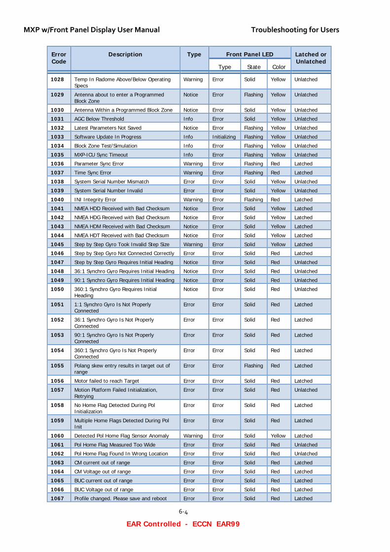
MXP w/Front Panel Display User Manual Troubleshooting for Users
6-4
EAR Controlled - ECCN EAR99
Error Code
Description Type Front Panel LED Latched or Unlatched
Type State Color
1028 Temp In Radome Above/Below Operating Specs
Warning Error Solid Yellow Unlatched
1029 Antenna about to enter a Programmed Block Zone
Notice Error Flashing Yellow Unlatched
1030 Antenna Within a Programmed Block Zone Notice Error Solid Yellow Unlatched
1031 AGC Below Threshold Info Error Solid Yellow Unlatched
1032 Latest Parameters Not Saved Notice Error Flashing Yellow Unlatched
1033 Software Update In Progress Info Initializing Flashing Yellow Unlatched
1034 Block Zone Test/Simulation Info Error Flashing Yellow Unlatched
1035 MXP-ICU Sync Timeout Info Error Flashing Yellow Unlatched
1036 Parameter Sync Error Warning Error Flashing Red Latched
1037 Time Sync Error Warning Error Flashing Red Latched
1038 System Serial Number Mismatch Error Error Solid Yellow Unlatched
1039 System Serial Number Invalid Error Error Solid Yellow Unlatched
1040 INI Integrity Error Warning Error Flashing Red Latched
1041 NMEA HDD Received with Bad Checksum Notice Error Solid Yellow Latched
1042 NMEA HDG Received with Bad Checksum Notice Error Solid Yellow Latched
1043 NMEA HDM Received with Bad Checksum Notice Error Solid Yellow Latched
1044 NMEA HDT Received with Bad Checksum Notice Error Solid Yellow Latched
1045 Step by Step Gyro Took Invalid Step Size Warning Error Solid Yellow Latched
1046 Step by Step Gyro Not Connected Correctly Error Error Solid Red Latched
1047 Step by Step Gyro Requires Initial Heading Notice Error Solid Red Unlatched
1048 36:1 Synchro Gyro Requires Initial Heading Notice Error Solid Red Unlatched
1049 90:1 Synchro Gyro Requires Initial Heading Notice Error Solid Red Unlatched
1050 360:1 Synchro Gyro Requires Initial Heading
Notice Error Solid Red Unlatched
1051 1:1 Synchro Gyro Is Not Properly Connected
Error Error Solid Red Latched
1052 36:1 Synchro Gyro Is Not Properly Connected
Error Error Solid Red Latched
1053 90:1 Synchro Gyro Is Not Properly Connected
Error Error Solid Red Latched
1054 360:1 Synchro Gyro Is Not Properly Connected
Error Error Solid Red Latched
1055 Polang skew entry results in target out of range
Error Error Flashing Red Latched
1056 Motor failed to reach Target Error Error Solid Red Latched
1057 Motion Platform Failed Initialization, Retrying
Error Error Solid Red Unlatched
1058 No Home Flag Detected During Pol Initialization
Error Error Solid Red Latched
1059 Multiple Home Flags Detected During Pol Init
Error Error Solid Red Latched
1060 Detected Pol Home Flag Sensor Anomaly Warning Error Solid Yellow Latched
1061 Pol Home Flag Measured Too Wide Error Error Solid Red Unlatched
1062 Pol Home Flag Found In Wrong Location Error Error Solid Red Unlatched
1063 CM current out of range Error Error Solid Red Latched
1064 CM Voltage out of range Error Error Solid Red Latched
1065 BUC current out of range Error Error Solid Red Latched
1066 BUC Voltage out of range Error Error Solid Red Latched
1067 Profile changed. Please save and reboot Error Error Solid Red Latched
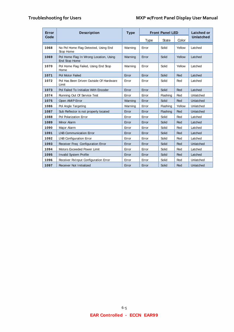
Troubleshooting for Users MXP w/Front Panel Display User Manual
6-5
EAR Controlled - ECCN EAR99
Error Code
Description Type Front Panel LED Latched or Unlatched
Type State Color
1068 No Pol Home Flag Detected, Using End Stop Home
Warning Error Solid Yellow Latched
1069 Pol Home Flag In Wrong Location, Using End Stop Home
Warning Error Solid Yellow Latched
1070 Pol Home Flag Failed, Using End Stop Home
Warning Error Solid Yellow Latched
1071 Pol Motor Failed Error Error Solid Red Latched
1072 Pol Has Been Driven Outside Of Hardware Limit
Error Error Solid Red Latched
1073 Pol Failed To Initialize With Encoder Error Error Solid Red Latched
1074 Running Out Of Service Test Error Error Flashing Red Unlatched
1075 Open AMIP Error Warning Error Solid Red Unlatched
1086 Pol Angle Targeting Warning Error Flashing Yellow Unlatched
1087 Sub Reflector is not properly located Error Error Flashing Red Unlatched
1088 Pol Polarization Error Error Error Solid Red Latched
1089 Minor Alarm Error Error Solid Red Latched
1090 Major Alarm Error Error Solid Red Latched
1091 LNB Communication Error Error Error Solid Red Latched
1092 LNB Configuration Error Error Error Solid Red Latched
1093 Receiver Freq Configuration Error Error Error Solid Red Unlatched
1094 Motors Exceeded Power Limit Error Error Solid Red Latched
1095 Invalid System Profile Error Error Solid Red Latched
1096 Receiver RxInput Configuration Error Error Error Solid Red Unlatched
1097 Receiver Not Initialized Error Error Solid Red Unlatched
MXP w/Front Panel Display User Manual Troubleshooting for Users
6-6
EAR Controlled - ECCN EAR99
This Page Intentionally Left Blank
Glossary of Terms MXP w/Front Panel Display User Manual
7-1
EAR Controlled - ECCN EAR99
7. Glossary of Terms
ACU (Antenna Control Unit) – The ACU is the below-decks electronic equipment that controls the antenna.
ADE (Above Decks Equipment) – The ADE includes the Sea Tel antenna, and its fiberglass radome, because they are on a higher deck or mast location outside the ship. Your ADE may include a Base frame, Legs, Braces, and may even have a marine air conditioner.
AGC (Automatic Gain Control) – A digital representation of the actual signal level being received from the satellite.
Antenna – This is entire assembly including the dish (reflector), antenna support structure (but not the pedestal), enclosure (radome), mechanical drive mechanism, etc. The antenna includes an integrated preamplifier, waveguides, and other electronic components that are directly connected to the antenna assembly.
AZ (Azimuth) – Clockwise /Counter Clockwise Rotation of the Antenna
BDE (Below Decks Equipment) – The MXP, satellite modem, satellite receivers, signal processing and distribution equipment that is associated with this type of system.
BLOCK (Blockage) – The signal from a satellite can be blocked by the superstructure of the ship, cranes, buildings, trees, or other obstructions, which are between the satellite (out in space directly above the equator) and the Sea Tel antenna. These obstacles block the signal, preventing it from reaching the antenna.
bps (Bits Per Second) – The speed at which a data signal carries information. It is commonly expressed in thousands of bits per second (kbps).
CFE (Customer Furnished Equipment) – Modem, Router, cables, uninterruptable power supply (UPS), etc.
CL (CROSS-LEVEL) – Tilt (left-right) of the antenna.
Dish (Part of the antenna) — It is a parabolic reflector, which is a curved surface with the cross-sectional shape of a parabola, used to direct radio and microwaves. The most common form is shaped like a dish. Often it is used synonymously with Reflector.
EL (ELEVATION) – The pointing-angle of the satellite antenna dish/reflector, between the horizon (0 degrees EL) and the zenith (directly overhead at 90 degrees EL).
ERROR – Name of an LED on the front panel. OFF indicates that no errors have occurred.
Favorite Satellite – Any satellite that is in the Select Satellite dropdown list of satellites. The list is in the Satellite Selection section of the Configuration > Satellite > Satellite Configuration page.
GPS (Global Positioning System) – A device that uses satellites to provide accurate Latitude and Longitude position of the ship.
GUI (Graphical User Interface) — Refers to the Graphical User Interface of the MXP ACU.
Gyrocompass – A device on the ship that provides the true heading of the ship, relative to true North. It is a non-magnetic compass, based on a fast-spinning disc and the rotation of the Earth. Gyrocompasses are used for navigation on ships, because they find true north as determined by the rotation of the Earth, which is more useful than magnetic north. They are not affected by ferromagnetic materials, such as a steel hull, which changes the magnetic field.
Horiz (Horizontal) – Horizontal linear polarity satellite signal.
ICU (Integrated Control Unit) – The remote controller mounted on the antenna pedestal. It is in constant communication with the ACU. They jointly control all the movements of the antenna.
INIT (Initializing) – Name of an LED on the front panel. OFF indicates that the system has finished initialization.
LED (Light Emitting Diode) – LEDs in various colors are used to indicate the status of parts of the system.
LHCP (Left Hand Circular Polarity) – Left-hand rotating circular polarity satellite signal.
LNB (Low Noise Block Down-Converter) — is the device mounted on a satellite antenna, which allows it to receive the satellite signal and convert it for use with the satellite modem or receivers.
MXP (Media Xchange Point™) – This is the Antenna Control Unit for the Sea Tel system. It uses HTML-based internal web pages that form the GUI that enables a user to access and operate the system.
MXP w/Front Panel Display User Manual Glossary of Terms
7-2
EAR Controlled - ECCN EAR99
Polang (Polarization Angle)
POWER – Name of an LED on the front panel. ON (Solid Green) indicates that the MXP boot sequence is complete, and the system power is ON (normal).
Radome – A structural, weatherproof enclosure that protects a microwave antenna.
Reflector (Part of the antenna) — It is a parabolic reflector, which is a curved surface with the cross-sectional shape of a parabola, used to direct radio and microwaves (radar). The most common form is shaped like a dish. Often it is used synonymously with Dish.
Relative AZ — This is the azimuth-pointing angle of the antenna relative to the bow of the ship. It is 000.0 (360.0) when the antenna is inline with the bow, 090.0 when the antenna is directly to starboard, 180.0 when directly aft and 270.0 when directly to port.
RHCP (Right Hand Circular Polarity) – Right hand rotating circular polarity satellite signal.
RMA (Return Material Authorization) – An RMA number must be obtained prior to returning a part for repair or replacement.
SCPC (Single Channel Per Carrier)
SEARCH (Searching) – OFF indicates that antenna is not searching.
STABILIZATION – Decoupling of the ships motion from the stabilized portion of the antenna, so that the antenna stays accurately pointed in 3-dimentional free space.
TARGET – Name of an LED on the front panel. OFF indicates that the antenna has finished targeting a satellite.
TRACK (Tracking) – ON (Solid Green) indicates that the MXP has identified and is actively tracking the desired satellite to optimize the signal level (AGC).
VSAT (Very Small Aperture Terminal) It refers to an antenna that is used to send and receive signals to or from a satellite for broadband services.
Vert (Vertical) – Vertical linear polarity.
Technical Contacts MXP w/Front Panel Display User Manual
8-1
EAR Controlled - ECCN EAR99
8. Technical Contacts Your first technical contact always should be your Dealer, from whom you originally purchased the system. This is usually the fastest way to have your problem resolved. If your Dealer cannot resolve the problem, then they will contact Sea Tel directly and work together to resolve the problem.
For your reference, please write in the following information:
Dealer Name: ______________________________________________________________________
Dealer Address _____________________________________________________________________
Dealer Phone ______________________________________________________________________
Dealer Fax _________________________________________________________________________
Dealer Email Address ________________________________________________________________
If, for some reason, you cannot contact your Dealer, then you can contact Sea Tel Service:
Sea Tel Inc., a Cobham SATCOM company 4030 Nelson Ave. Concord, CA 94520 USA
Email to GCS service: [email protected] Telephone: +1 (925) 798-2399
MXP w/Front Panel Display User Manual Technical Contacts
8-2
EAR Controlled - ECCN EAR99
This Page Intentionally Left Blank
![%ROHVáDZLHF 3RZLDWRZH *LPQD]MXP …¡DZD *yUQD *LPQD]MXP QU 6=.2/1$ 'REURFLQ 1LHSXEOLF]QH *LPQD]MXP 6SHFMDOQH %DMHF]QH :]JyU]D .R FLXV]NL àDJLHZQLNL *LPQD]MXP LP 3LDVWyZ O …](https://img.pdfslide.net/doc/110x75/5c9b454209d3f2404d8ba62c/rohvadzlhf-3rzldwrzh-lpqdmxp-dzd-yuqd-lpqdmxp-qu-621-reurflq-1lhsxeolfqh.jpg)