Embed Size (px)
Citation preview

Sealing and Isolating Gaskets
Flange Isolation Kits
Isolation Sleeves and Washers
Specifications and Ordering Guide
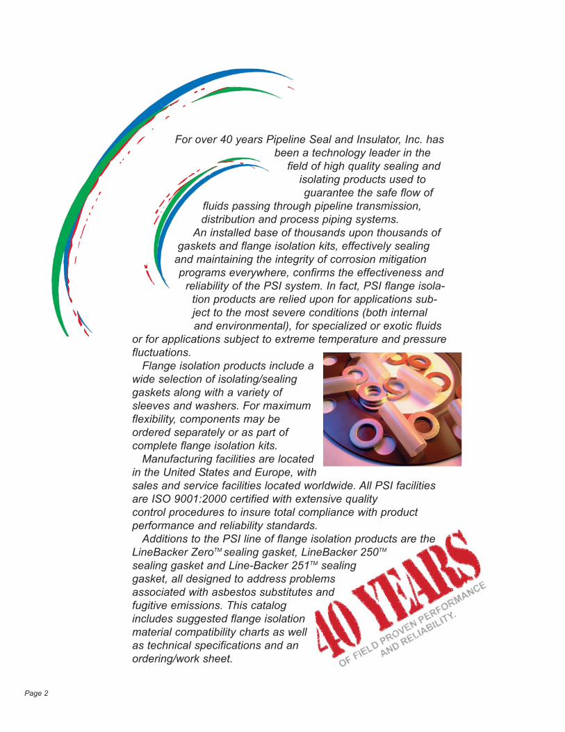
For over 40 years Pipeline Seal and Insulator, Inc. hasbeen a technology leader in the
field of high quality sealing andisolating products used toguarantee the safe flow of
fluids passing through pipeline transmission, distribution and process piping systems.
An installed base of thousands upon thousands ofgaskets and flange isolation kits, effectively sealing
and maintaining the integrity of corrosion mitigationprograms everywhere, confirms the effectiveness and
reliability of the PSI system. In fact, PSI flange isola-tion products are relied upon for applications sub-ject to the most severe conditions (both internaland environmental), for specialized or exotic fluids
or for applications subject to extreme temperature and pressurefluctuations.
Flange isolation products include awide selection of isolating/sealinggaskets along with a variety ofsleeves and washers. For maximumflexibility, components may beordered separately or as part ofcomplete flange isolation kits.
Manufacturing facilities are locatedin the United States and Europe, withsales and service facilities located worldwide. All PSI facilitiesare ISO 9001:2000 certified with extensive qualitycontrol procedures to insure total compliance with productperformance and reliability standards.
Additions to the PSI line of flange isolation products are theLineBacker ZeroTM sealing gasket, LineBacker 250TM
sealing gasket and Line-Backer 251TM sealinggasket, all designed to address problemsassociated with asbestos substitutes andfugitive emissions. This catalogincludes suggested flange isolationmaterial compatibility charts as wellas technical specifications and anordering/work sheet.
Page 2
PSI Isolating Gasket Types
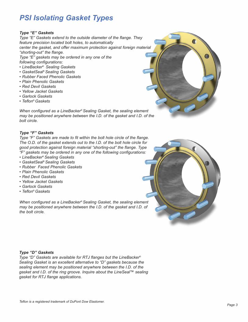
Type “E” GasketsType “E” Gaskets extend to the outside diameter of the flange. They feature precision located bolt holes, to automaticallycenter the gasket, and offer maximum protection against foreign material“shorting-out” the flange. Type “E” gaskets may be ordered in any one of thefollowing configurations:• LineBacker® Sealing Gaskets• GasketSeal® Sealing Gaskets• Rubber Faced Phenolic Gaskets• Plain Phenolic Gaskets• Red Devil Gaskets• Yellow Jacket Gaskets• Garlock Gaskets• Teflon® Gaskets
When configured as a LineBacker® Sealing Gasket, the sealing elementmay be positioned anywhere between the I.D. of the gasket and I.D. of thebolt circle.
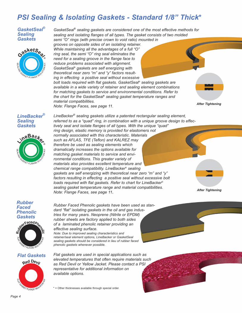
Type “F” GasketsType “F” Gaskets are made to fit within the bolt hole circle of the flange.The O.D. of the gasket extends out to the I.D. of the bolt hole circle forgood protection against foreign material “shorting-out” the flange. Type“F” gaskets may be ordered in any one of the following configurations:• LineBacker® Sealing Gaskets• GasketSeal® Sealing Gaskets• Rubber Faced Phenolic Gaskets• Plain Phenolic Gaskets• Red Devil Gaskets• Yellow Jacket Gaskets• Garlock Gaskets• Teflon® Gaskets
When configured as a LineBacker® Sealing Gasket, the sealing elementmay be positioned anywhere between the I.D. of the gasket and I.D. ofthe bolt circle.
Type “D” GasketsType “D” Gaskets are available for RTJ flanges but the LineBacker®
Sealing Gasket is an excellent alternative to “D” gaskets because thesealing element may be positioned anywhere between the I.D. of thegasket and I.D. of the ring groove. Inquire about the LineSeal™ sealinggasket for RTJ flange applications.
Teflon is a registered trademark of DuPont Dow Elastomer.Page 3
After Tightening
PSI Sealing & Isolating Gaskets - Standard 1/8” Thick*GasketSeal®SealingGaskets
LineBacker®
SealingGaskets
RubberFacedPhenolicGaskets
Flat Gaskets
GasketSeal® sealing gaskets are considered one of the most effective methods forsealing and isolating flanges of all types. The gasket consists of two moldedsemi “O” rings (with precise crown to void ratio) mounted ingrooves on opposite sides of an isolating retainer.While maintaining all the advantages of a full “O”ring seal, the semi “O” ring seal eliminates theneed for a sealing groove in the flange face toreduce problems associated with alignment.GasketSeal® gaskets are self energizing withtheoretical near zero “m” and “y” factors result-ing in effecting a positive seal without excessivebolt loads required with flat gaskets. GasketSeal® sealing gaskets areavailable in a wide variety of retainer and sealing element combinationsfor matching gaskets to service and environmental conditions. Refer tothe chart for the GasketSeal® sealing gasket temperature ranges andmaterial compatibilities. Note: Flange Faces, see page 11.
Rubber Faced Phenolic gaskets have been used as stan-dard “flat” isolating gaskets in the oil and gas indus-tries for many years. Neoprene (Nitrile or EPDM)rubber sheets are factory applied to both sidesof a laminated phenolic retainer providing an effective sealing surface.Note: Due to improved sealing characteristics and retainer/seal element options, LineBacker or GasketSealsealing gaskets should be considered in lieu of rubber facedphenolic gaskets whenever possible.
Page 4
* = Other thicknesses available through special order.
Flat gaskets are used in special applications such aselevated temperatures that often require materials suchas Red Devil or Yellow Jacket. Please contact a PSIrepresentative for additional information onavailable options.
LineBacker® sealing gaskets utilize a patented rectangular sealing element,referred to as a “quad” ring, in combination with a unique groove design to effec-tively seal and isolate flanges of all types. With the unique “quad”ring design, elastic memory is provided for elastomers notnormally associated with this characteristic. Materialssuch as AFLAS, TFE (Teflon) and KALREZ maytherefore be used as sealing elements which dramatically increases the options available formatching gasket materials to service and envi-ronmental conditions. This greater variety ofmaterials also provides excellent temperature andchemical range compatibility. LineBacker® sealinggaskets are self energizing with theoretical near zero “m” and “y”factors resulting in effecting a positive seal without excessive boltloads required with flat gaskets. Refer to chart for LineBacker®
sealing gasket temperature range and material compatibilities.Note: Flange Faces, see page 11. After Tightening
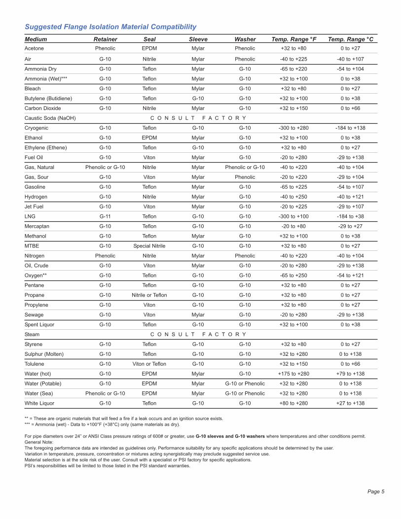
Suggested Flange Isolation Material CompatibilityMedium Retainer Seal Sleeve Washer Temp. Range °F Temp. Range °C Acetone Phenolic EPDM Mylar Phenolic +32 to +80 0 to +27
Air G-10 Nitrile Mylar Phenolic -40 to +225 -40 to +107
Ammonia Dry G-10 Teflon Mylar G-10 -65 to +220 -54 to +104
Ammonia (Wet)*** G-10 Teflon Mylar G-10 +32 to +100 0 to +38
Bleach G-10 Teflon Mylar G-10 +32 to +80 0 to +27
Butylene (Butidiene) G-10 Teflon G-10 G-10 +32 to +100 0 to +38
Carbon Dioxide G-10 Nitrile Mylar G-10 +32 to +150 0 to +66
Caustic Soda (NaOH) C O N S U L T F A C T O R Y
Cryogenic G-10 Teflon G-10 G-10 -300 to +280 -184 to +138
Ethanol G-10 EPDM Mylar G-10 +32 to +100 0 to +38
Ethylene (Ethene) G-10 Teflon G-10 G-10 +32 to +80 0 to +27
Fuel Oil G-10 Viton Mylar G-10 -20 to +280 -29 to +138
Gas, Natural Phenolic or G-10 Nitrile Mylar Phenolic or G-10 -40 to +220 -40 to +104
Gas, Sour G-10 Viton Mylar Phenolic -20 to +220 -29 to +104
Gasoline G-10 Teflon Mylar G-10 -65 to +225 -54 to +107
Hydrogen G-10 Nitrile Mylar G-10 -40 to +250 -40 to +121
Jet Fuel G-10 Viton Mylar G-10 -20 to +225 -29 to +107
LNG G-11 Teflon G-10 G-10 -300 to +100 -184 to +38
Mercaptan G-10 Teflon G-10 G-10 -20 to +80 -29 to +27
Methanol G-10 Teflon Mylar G-10 +32 to +100 0 to +38
MTBE G-10 Special Nitrile G-10 G-10 +32 to +80 0 to +27
Nitrogen Phenolic Nitrile Mylar Phenolic -40 to +220 -40 to +104
Oil, Crude G-10 Viton Mylar G-10 -20 to +280 -29 to +138
Oxygen** G-10 Teflon G-10 G-10 -65 to +250 -54 to +121
Pentane G-10 Teflon G-10 G-10 +32 to +80 0 to +27
Propane G-10 Nitrile or Teflon G-10 G-10 +32 to +80 0 to +27
Propylene G-10 Viton G-10 G-10 +32 to +80 0 to +27
Sewage G-10 Viton Mylar G-10 -20 to +280 -29 to +138
Spent Liquor G-10 Teflon G-10 G-10 +32 to +100 0 to +38
Steam C O N S U L T F A C T O R Y
Styrene G-10 Teflon G-10 G-10 +32 to +80 0 to +27
Sulphur (Molten) G-10 Teflon G-10 G-10 +32 to +280 0 to +138
Tolulene G-10 Viton or Teflon G-10 G-10 +32 to +150 0 to +66
Water (hot) G-10 EPDM Mylar G-10 +175 to +280 +79 to +138
Water (Potable) G-10 EPDM Mylar G-10 or Phenolic +32 to +280 0 to +138
Water (Sea) Phenolic or G-10 EPDM Mylar G-10 or Phenolic +32 to +280 0 to +138
White Liquor G-10 Teflon G-10 G-10 +80 to +280 +27 to +138
** = These are organic materials that will feed a fire if a leak occurs and an ignition source exists.
*** = Ammonia (wet) - Data to +100°F (+38°C) only (same materials as dry).
For pipe diameters over 24” or ANSI Class pressure ratings of 600# or greater, use G-10 sleeves and G-10 washers where temperatures and other conditions permit.
General Note:
The foregoing performance data are intended as guidelines only. Performance suitability for any specific applications should be determined by the user.
Variation in temperature, pressure, concentration or mixtures acting synergistically may preclude suggested service use.
Material selection is at the sole risk of the user. Consult with a specialist or PSI factory for specific applications.
PSI’s responsibilities will be limited to those listed in the PSI standard warranties.
Page 5
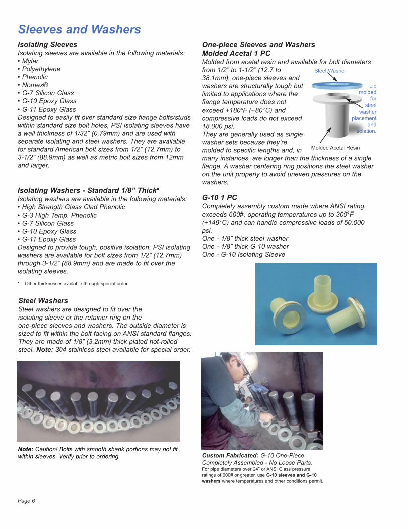
Sleeves and WashersIsolating SleevesIsolating sleeves are available in the following materials:• Mylar• Polyethylene• Phenolic• Nomex®• G-7 Silicon Glass• G-10 Epoxy Glass• G-11 Epoxy GlassDesigned to easily fit over standard size flange bolts/studswithin standard size bolt holes, PSI isolating sleeves havea wall thickness of 1/32” (0.79mm) and are used with separate isolating and steel washers. They are availablefor standard American bolt sizes from 1/2” (12.7mm) to 3-1/2” (88.9mm) as well as metric bolt sizes from 12mmand larger.
Isolating Washers - Standard 1/8” Thick* Isolating washers are available in the following materials:• High Strength Glass Clad Phenolic• G-3 High Temp. Phenolic• G-7 Silicon Glass• G-10 Epoxy Glass• G-11 Epoxy GlassDesigned to provide tough, positive isolation. PSI isolatingwashers are available for bolt sizes from 1/2” (12.7mm)through 3-1/2” (88.9mm) and are made to fit over the isolating sleeves.
One-piece Sleeves and WashersMolded Acetal 1 PCMolded from acetal resin and available for bolt diametersfrom 1/2” to 1-1/2” (12.7 to38.1mm), one-piece sleeves andwashers are structurally tough butlimited to applications where theflange temperature does notexceed +180ºF (+80°C) andcompressive loads do not exceed18,000 psi.They are generally used as singlewasher sets because they’remolded to specific lengths and, inmany instances, are longer than the thickness of a singleflange. A washer centering ring positions the steel washeron the unit properly to avoid uneven pressures on thewashers.
G-10 1 PCCompletely assembly custom made where ANSI ratingexceeds 600#, operating temperatures up to 300°F(+149°C) and can handle compressive loads of 50,000psi.One - 1/8” thick steel washerOne - 1/8” thick G-10 washerOne - G-10 Isolating Sleeve
Steel WashersSteel washers are designed to fit over theisolating sleeve or the retainer ring on theone-piece sleeves and washers. The outside diameter issized to fit within the bolt facing on ANSI standard flanges.They are made of 1/8” (3.2mm) thick plated hot-rolledsteel. Note: 304 stainless steel available for special order.
Page 6
Custom Fabricated: G-10 One-PieceCompletely Assembled - No Loose Parts. For pipe diameters over 24” or ANSI Class pressure
ratings of 600# or greater, use G-10 sleeves and G-10
washers where temperatures and other conditions permit.
* = Other thicknesses available through special order.
Note: Caution! Bolts with smooth shank portions may not fitwithin sleeves. Verify prior to ordering.
Molded Acetal Resin
Steel Washer
Lip
molded
for
steel
washer
placement
and
isolation.
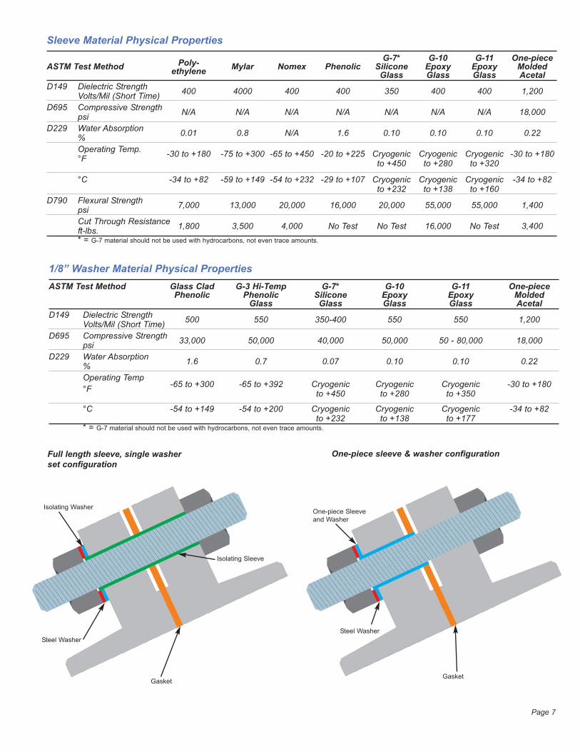
Sleeve Material Physical PropertiesG-7* G-10 G-11 One-piece
ASTM Test Method Poly- Mylar Nomex Phenolic Silicone Epoxy Epoxy Moldedethylene Glass Glass Glass AcetalD149 Dielectric Strength
Volts/Mil (Short Time) 400 4000 400 400 350 400 400 1,200
D695 Compressive Strengthpsi N/A N/A N/A N/A N/A N/A N/A 18,000
D229 Water Absorption% 0.01 0.8 N/A 1.6 0.10 0.10 0.10 0.22
Operating Temp.°F -30 to +180 -75 to +300 -65 to +450 -20 to +225 Cryogenic Cryogenic Cryogenic -30 to +180
to +450 to +280 to +320
°C -34 to +82 -59 to +149 -54 to +232 -29 to +107 Cryogenic Cryogenic Cryogenic -34 to +82to +232 to +138 to +160
D790 Flexural Strengthpsi 7,000 13,000 20,000 16,000 20,000 55,000 55,000 1,400
Cut Through Resistanceft-lbs. 1,800 3,500 4,000 No Test No Test 16,000 No Test 3,400* = G-7 material should not be used with hydrocarbons, not even trace amounts.
1/8” Washer Material Physical PropertiesASTM Test Method Glass Clad G-3 Hi-Temp G-7* G-10 G-11 One-piece
Phenolic Phenolic Silicone Epoxy Epoxy MoldedGlass Glass Glass Glass Acetal
D149 Dielectric StrengthVolts/Mil (Short Time) 500 550 350-400 550 550 1,200
D695 Compressive Strengthpsi 33,000 50,000 40,000 50,000 50 - 80,000 18,000
D229 Water Absorption% 1.6 0.7 0.07 0.10 0.10 0.22
Operating Temp°F -65 to +300 -65 to +392 Cryogenic Cryogenic Cryogenic -30 to +180
to +450 to +280 to +350
°C -54 to +149 -54 to +200 Cryogenic Cryogenic Cryogenic -34 to +82to +232 to +138 to +177
* = G-7 material should not be used with hydrocarbons, not even trace amounts.
One-piece sleeve & washer configurationFull length sleeve, single washerset configuration
Isolating Washer
Isolating Sleeve
One-piece Sleeve
and Washer
Steel Washer
Steel Washer
GasketGasket
Page 7
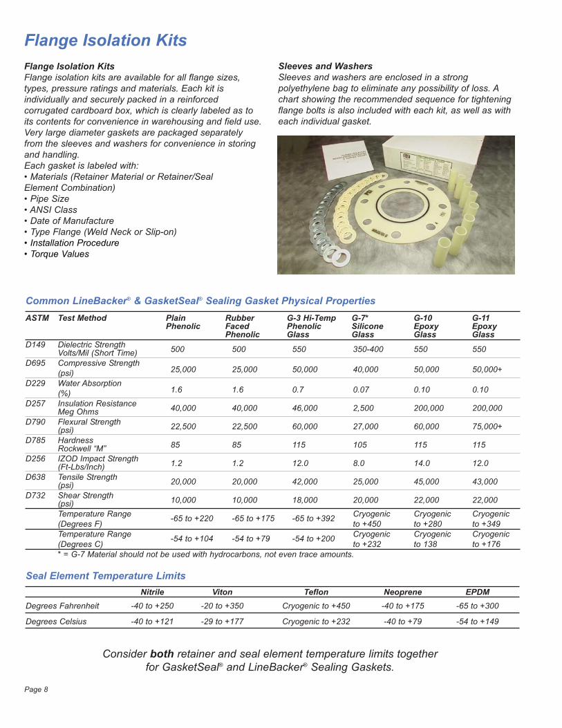
Flange Isolation KitsFlange Isolation KitsFlange isolation kits are available for all flange sizes,types, pressure ratings and materials. Each kit isindividually and securely packed in a reinforcedcorrugated cardboard box, which is clearly labeled as toits contents for convenience in warehousing and field use.Very large diameter gaskets are packaged separatelyfrom the sleeves and washers for convenience in storingand handling.Each gasket is labeled with:• Materials (Retainer Material or Retainer/SealElement Combination) • Pipe Size• ANSI Class• Date of Manufacture• Type Flange (Weld Neck or Slip-on)• Installation Procedure• Torque Values
Common LineBacker® & GasketSeal® Sealing Gasket Physical Properties ASTM Test Method Plain Rubber G-3 Hi-Temp G-7* G-10 G-11
Phenolic Faced Phenolic Silicone Epoxy EpoxyPhenolic Glass Glass Glass Glass
D149 Dielectric StrengthVolts/Mil (Short Time) 500 500 550 350-400 550 550
D695 Compressive Strength(psi) 25,000 25,000 50,000 40,000 50,000 50,000+
D229 Water Absorption(%) 1.6 1.6 0.7 0.07 0.10 0.10
D257 Insulation ResistanceMeg Ohms 40,000 40,000 46,000 2,500 200,000 200,000
D790 Flexural Strength(psi) 22,500 22,500 60,000 27,000 60,000 75,000+
D785 HardnessRockwell “M” 85 85 115 105 115 115
D256 IZOD Impact Strength(Ft-Lbs/Inch) 1.2 1.2 12.0 8.0 14.0 12.0
D638 Tensile Strength(psi) 20,000 20,000 42,000 25,000 45,000 43,000
D732 Shear Strength(psi) 10,000 10,000 18,000 20,000 22,000 22,000
Temperature Range -65 to +220 -65 to +175 -65 to +392 Cryogenic Cryogenic Cryogenic(Degrees F) to +450 to +280 to +349Temperature Range -54 to +104 -54 to +79 -54 to +200 Cryogenic Cryogenic Cryogenic(Degrees C) to +232 to 138 to +176* = G-7 Material should not be used with hydrocarbons, not even trace amounts.
Consider both retainer and seal element temperature limits togetherfor GasketSeal® and LineBacker® Sealing Gaskets.
Seal Element Temperature LimitsNitrile Viton Teflon Neoprene EPDM
Degrees Fahrenheit -40 to +250 -20 to +350 Cryogenic to +450 -40 to +175 -65 to +300
Degrees Celsius -40 to +121 -29 to +177 Cryogenic to +232 -40 to +79 -54 to +149
Sleeves and WashersSleeves and washers are enclosed in a strongpolyethylene bag to eliminate any possibility of loss. Achart showing the recommended sequence for tighteningflange bolts is also included with each kit, as well as witheach individual gasket.
Page 8
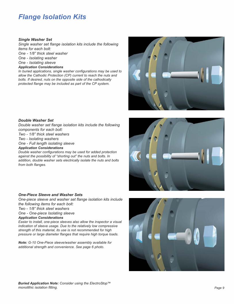
Single Washer SetSingle washer set flange isolation kits include the followingitems for each bolt:One - 1/8” thick steel washerOne - Isolating washerOne - Isolating sleeveApplication ConsiderationsIn buried applications, single washer configurations may be used toallow the Cathodic Protection (CP) current to reach the nuts andbolts. If desired, nuts on the opposite side of the cathodicallyprotected flange may be included as part of the CP system.
Flange Isolation Kits
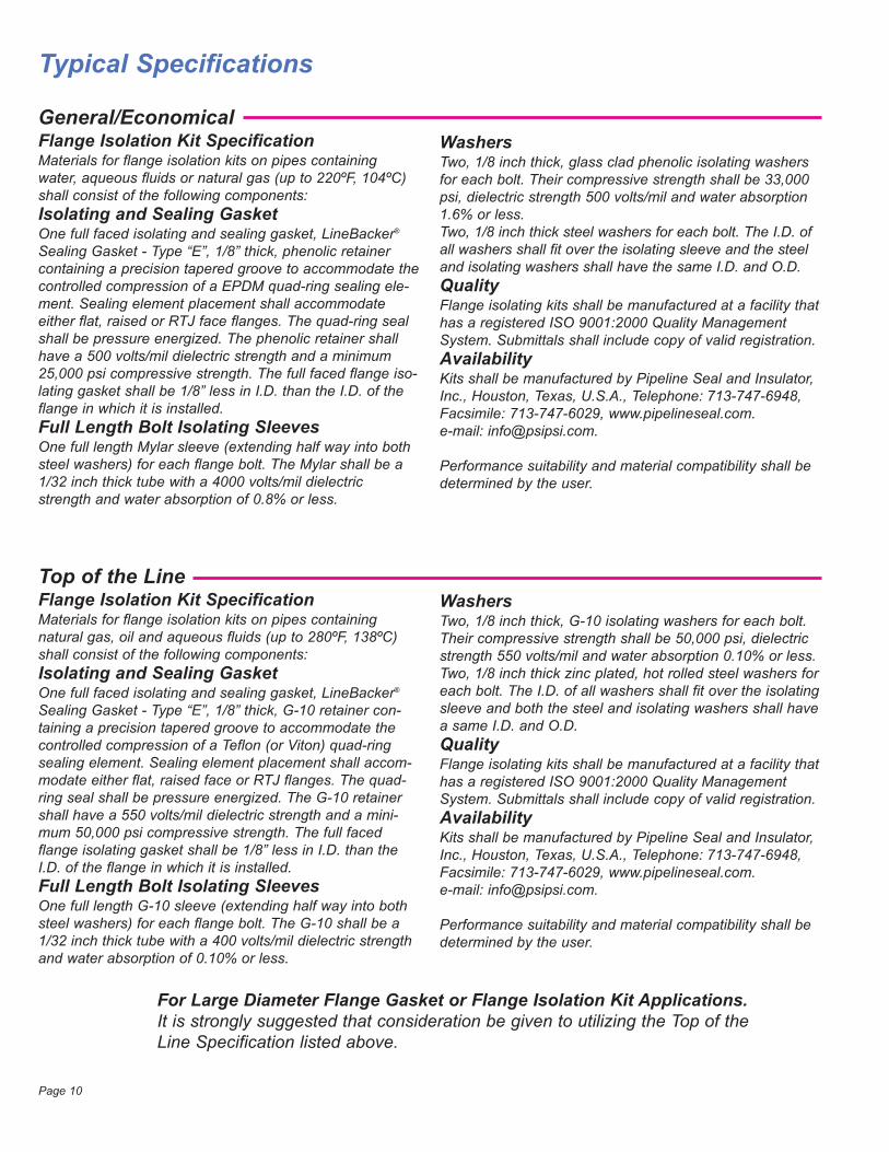
Double Washer Set Double washer set flange isolation kits include the followingcomponents for each bolt:Two - 1/8” thick steel washersTwo - Isolating washersOne - Full length isolating sleeveApplication ConsiderationsDouble washer configurations may be used for added protectionagainst the possibility of “shorting out” the nuts and bolts. Inaddition, double washer sets electrically isolate the nuts and boltsfrom both flanges.
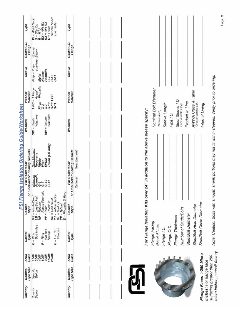
One-Piece Sleeve and Washer SetsOne-piece sleeve and washer set flange isolation kits includethe following items for each bolt:Two - 1/8” thick steel washersOne - One-piece Isolating sleeveApplication ConsiderationsEasier to install, one-piece sleeves also allow the inspector a visualindication of sleeve usage. Due to the relatively low compressivestrength of this material, its use is not recommended for highpressure or large diameter flanges that require high torque loads.
Note: G-10 One-Piece sleeve/washer assembly available for additional strength and convenience. See page 6 photo.
Page 9Buried Application Note: Consider using the ElectroStop™ monolithic isolation fitting.
Typical Specifications
General/EconomicalFlange Isolation Kit SpecificationMaterials for flange isolation kits on pipes containingwater, aqueous fluids or natural gas (up to 220ºF, 104ºC)shall consist of the following components:Isolating and Sealing GasketOne full faced isolating and sealing gasket, LineBacker®
Sealing Gasket - Type “E”, 1/8” thick, phenolic retainercontaining a precision tapered groove to accommodate thecontrolled compression of a EPDM quad-ring sealing ele-ment. Sealing element placement shall accommodateeither flat, raised or RTJ face flanges. The quad-ring sealshall be pressure energized. The phenolic retainer shallhave a 500 volts/mil dielectric strength and a minimum25,000 psi compressive strength. The full faced flange iso-lating gasket shall be 1/8” less in I.D. than the I.D. of theflange in which it is installed.Full Length Bolt Isolating SleevesOne full length Mylar sleeve (extending half way into bothsteel washers) for each flange bolt. The Mylar shall be a1/32 inch thick tube with a 4000 volts/mil dielectricstrength and water absorption of 0.8% or less.
Top of the LineFlange Isolation Kit SpecificationMaterials for flange isolation kits on pipes containingnatural gas, oil and aqueous fluids (up to 280ºF, 138ºC)shall consist of the following components:Isolating and Sealing GasketOne full faced isolating and sealing gasket, LineBacker®
Sealing Gasket - Type “E”, 1/8” thick, G-10 retainer con-taining a precision tapered groove to accommodate thecontrolled compression of a Teflon (or Viton) quad-ringsealing element. Sealing element placement shall accom-modate either flat, raised face or RTJ flanges. The quad-ring seal shall be pressure energized. The G-10 retainershall have a 550 volts/mil dielectric strength and a mini-mum 50,000 psi compressive strength. The full facedflange isolating gasket shall be 1/8” less in I.D. than theI.D. of the flange in which it is installed.Full Length Bolt Isolating SleevesOne full length G-10 sleeve (extending half way into bothsteel washers) for each flange bolt. The G-10 shall be a1/32 inch thick tube with a 400 volts/mil dielectric strengthand water absorption of 0.10% or less.
WashersTwo, 1/8 inch thick, glass clad phenolic isolating washersfor each bolt. Their compressive strength shall be 33,000psi, dielectric strength 500 volts/mil and water absorption1.6% or less.Two, 1/8 inch thick steel washers for each bolt. The I.D. ofall washers shall fit over the isolating sleeve and the steeland isolating washers shall have the same I.D. and O.D.QualityFlange isolating kits shall be manufactured at a facility thathas a registered ISO 9001:2000 Quality ManagementSystem. Submittals shall include copy of valid registration.AvailabilityKits shall be manufactured by Pipeline Seal and Insulator,Inc., Houston, Texas, U.S.A., Telephone: 713-747-6948,Facsimile: 713-747-6029, www.pipelineseal.com.e-mail: [email protected].
Performance suitability and material compatibility shall bedetermined by the user.
WashersTwo, 1/8 inch thick, G-10 isolating washers for each bolt.Their compressive strength shall be 50,000 psi, dielectricstrength 550 volts/mil and water absorption 0.10% or less.Two, 1/8 inch thick zinc plated, hot rolled steel washers foreach bolt. The I.D. of all washers shall fit over the isolatingsleeve and both the steel and isolating washers shall havea same I.D. and O.D.QualityFlange isolating kits shall be manufactured at a facility thathas a registered ISO 9001:2000 Quality ManagementSystem. Submittals shall include copy of valid registration.AvailabilityKits shall be manufactured by Pipeline Seal and Insulator,Inc., Houston, Texas, U.S.A., Telephone: 713-747-6948,Facsimile: 713-747-6029, www.pipelineseal.com.e-mail: [email protected].
Performance suitability and material compatibility shall bedetermined by the user.
Page 10
For Large Diameter Flange Gasket or Flange Isolation Kit Applications.It is strongly suggested that consideration be given to utilizing the Top of theLine Specification listed above.
For
Flan
ge Is
olat
ion
Kits
ove
r 24
” in
add
ition
to th
e ab
ove
plea
se s
peci
fy:
Flan
ge F
acin
g (R
aise
d, R
TJ..e
tc)
——
——
——
——
——
——
——
——
—Fl
ange
I.D
.—
——
——
——
——
——
——
——
——
Flan
ge O
.D.
——
——
——
——
——
——
——
——
—Fl
ange
Thi
ckne
ss—
——
——
——
——
——
——
——
——
Num
ber o
f Stu
ds/B
olts
—
——
——
——
——
——
——
——
——
Stud
/Bol
t Dia
met
er—
——
——
——
——
——
——
——
——
Stud
/Bol
t Hol
e D
iam
eter
——
——
——
——
——
——
——
——
—St
ud/B
olt C
ircle
Dia
met
er—
——
——
——
——
——
——
——
——
Not
e: C
autio
n! B
olts
with
sm
ooth
sha
nk p
ortio
ns m
ay n
ot fi
t with
in s
leev
es. V
erify
prio
r to
orde
ring.
Nom
inal
Bol
t Dia
met
er(T
hrea
ds/In
ch)
——
——
——
——
——
——
——
——
——
——
——
——
——
Sle
eve
Leng
th—
——
——
——
——
——
——
——
——
—P
ipe
I.D.
——
——
——
——
——
——
——
——
——
Stee
l Sle
eve
I.D.
——
——
——
——
——
——
——
——
——
(For
Con
cret
e P
ipe)
Pro
duct
In L
ine
——
——
——
——
——
——
——
——
——
AWW
A C
lass
& T
able
——
——
——
——
——
——
——
——
——
(Or o
ther
sim
ilar s
td.)
Inte
rnal
Lin
ing
——
——
——
——
——
——
——
——
——
PSI F
lang
e Is
olat
ion
Ord
erin
g G
uide
/Wor
kshe
etQ
uant
ityN
omin
alA
NSI
Gas
ket
Gas
ket
For
Gas
ketS
eal®
Was
hers
Was
her
Slee
veG
aske
t I.D
.Ty
pePi
pe S
ize
Cla
ssTy
peSt
yle
or L
ineB
acke
r®Se
alin
g G
aske
tsM
ater
ial
Flan
geS
peci
fyS
peci
fy15
0#E
= W
ithG
S=
Gas
ketS
eal®
Ret
aine
rS
eal E
lem
ent
SW=
Sin
gle
1 PC
= 1
Pie
cePo
ly=
Pol
y-S
peci
fyW
= W
eld
Nec
kB
elow
Bel
ow30
0#B
olt H
oles
LB =
Lin
eBac
ker®
Phen
olic
Neo
pren
eW
ashe
rsA
ceta
let
hyle
neB
elow
S =
Slip
On
400#
NP
= R
ubbe
rG
-3N
itrile
Phen
= P
heno
licM
ylar
R =
RTJ
600#
F =
Rin
gFa
ced
Phe
nolic
G-7
Vito
nG
-3N
omex
BX
= A
PI B
X90
0#(N
o B
olt
PP =
Pla
inG
-10
EPD
MD
W=
Dou
ble
G-7
Phen
olic
RX
= A
PI R
X15
00#
Hol
es)
Phe
nolic
G-1
1Te
flon
(LB
onl
y)W
ashe
rsG
-10
G-7
O =
Oth
er25
00#
RD
= R
ed D
evil
G-1
0 1
PCG
-10
Den
ote
Spe
cs.
D =
For
RTJ
YJ =
Yel
low
Jac
ket
G-1
1G
-11
and
Tabl
eFl
ange
sG
L =
Gar
lock
TF =
Tef
lon®
D =
Phe
nolic
D R
ing
Qua
ntity
Nom
inal
AN
SIG
aske
tG
aske
tFo
r G
aske
tSea
l®W
ashe
rsW
ashe
rSl
eeve
Gas
ket I
.D.
Type
Pipe
Siz
eC
lass
Type
Styl
eor
Lin
eBac
ker®
Sea
ling
Gas
kets
Mat
eria
lFl
ange
Ret
aine
rS
eal E
lem
ent
Pag
e 11
Flan
ge F
aces
>25
0 M
icro
Inch
es: F
or fl
ange
face
su
rfaci
ng g
reat
er th
an 2
50m
icro
inch
es, c
onsu
lt fa
ctor
y.
Pipeline Seal and Insulator, Inc.
©2009 - Pipeline Seal and Insulator, Inc.
PSI-FIC-3/09
WarrantyAll products are warranted against failure caused bymanufacturing defects for a period of one year. Anyproduct found to be so defective and returned withinone year from date of shipment will be replaced withoutcharge. The above warranty is made in lieu of, and we disclaim,any and all other warranties, expressed or implied,including the warranties of merchantability andfitness for a particular purpose, and buyer agreesto accept the products without any suchwarranties.We hereby disclaim any obligation orliability for consequential damages, laborcosts or any other claims or liabilities of anykind whatsoever.
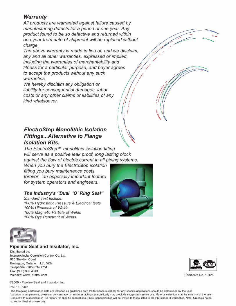
ElectroStop Monolithic IsolationFittings...Alternative to FlangeIsolation Kits.The ElectroStop™ monolithic isolation fittingwill serve as a positive leak proof, long lasting blockagainst the flow of electric current in all piping systems.When you bury the ElectroStop isolationfitting you bury maintenance costs forever - an especially important featurefor system operators and engineers.
The Industry’s “Dual ‘O’ Ring Seal”Standard Test Include:100% Hydrostatic Pressure & Electrical tests100% Ultrasonic of Welds100% Magnetic Particle of Welds100% Dye Penetrant of Welds
Certificate No. 10125
The foregoing performance data are intended as guidelines only. Performance suitability for any specific applications should be determined by the user.
Variation in temperature, pressure, concentration or mixtures acting synergistically may preclude suggested service use. Material selection is at the sole risk of the user.
Consult with a specialist or PSI factory for specific applications. PSI’s responsibilities will be limited to those listed in the PSI standard warranties. Note: Graphics not to
scale, for illustration use only.
Distributed by:Interprovincial Corrosion Control Co. Ltd.930 Sheldon CourtBurlington, Ontario L7L 5K6Telephone: (905) 634 7751Fax: (905) 333 4313Website: www.Rustrol.com