Embed Size (px)
Citation preview
IBIZ
Aow
ner’
sm
anua
l
auto emoción
fully to familiarise yourself with
l contribute to preserve its value.
s and parts exchange.
as this should be kept with the
ForewordThis owner's manual and the corresponding supplements should be read care
your vehicle.
Also, the regular care and maintenance and correct handling of the vehicle wil
For safety reasons, note the information concerning accessories, modification
If selling the vehicle, give all of the onboard documentation to the new owner
vehicle.

Contents 3
irst-aid kit, warning triangle, fire extinguisher*
uggage compartment . . . . . . . . . . . . . . . . . . . .
ting, Ventilation and Air conditioning . .
eating and ventilation . . . . . . . . . . . . . . . . . . .
ir conditioning* . . . . . . . . . . . . . . . . . . . . . . . . .
limatronic . . . . . . . . . . . . . . . . . . . . . . . . . . . . . .
eneral notes . . . . . . . . . . . . . . . . . . . . . . . . . . .
ing . . . . . . . . . . . . . . . . . . . . . . . . . . . . . . . . . . .
ddress . . . . . . . . . . . . . . . . . . . . . . . . . . . . . . . .
afety . . . . . . . . . . . . . . . . . . . . . . . . . . . . . . . . . .
nition lock . . . . . . . . . . . . . . . . . . . . . . . . . . . . .
tarting and stopping the engine . . . . . . . . . . .
anual gearbox . . . . . . . . . . . . . . . . . . . . . . . . . .
utomatic gearbox* . . . . . . . . . . . . . . . . . . . . . .
andbrake . . . . . . . . . . . . . . . . . . . . . . . . . . . . . .
ruise control system (CCS)* . . . . . . . . . . . . . . .
s and Maintenance . . . . . . . . . . . . .
lligent technology . . . . . . . . . . . . . . . . . . . . .
rakes . . . . . . . . . . . . . . . . . . . . . . . . . . . . . . . . .
nti-lock brake system and traction control ABS
lectronic stabilisation programme (ESP)* . . . .
ing and the environment . . . . . . . . . . . . . .
unning-in . . . . . . . . . . . . . . . . . . . . . . . . . . . . . .
xhaust gasses purification system . . . . . . . . . .
riving abroad . . . . . . . . . . . . . . . . . . . . . . . . . . .
railer towing . . . . . . . . . . . . . . . . . . . . . . . . . . . .
riving economically and with respect for the
nvironment . . . . . . . . . . . . . . . . . . . . . . . . . . . . .
116
116
119
119
122
125
128
130
130
131
132
133
136
137
141
142
147
147
147
148
149
151
151
152
153
158
160
Contents
The structure of this manual . . . . .
Content . . . . . . . . . . . . . . . . . . . . . . . . . . . . . . . .
Safety First . . . . . . . . . . . . . . . . . . . . . . . . . . .
Safe driving . . . . . . . . . . . . . . . . . . . . . . . . . . . . . .
Brief introduction . . . . . . . . . . . . . . . . . . . . . . . .
Proper sitting position for occupants . . . . . . . . .
Pedal area . . . . . . . . . . . . . . . . . . . . . . . . . . . . . .
Stowing luggage . . . . . . . . . . . . . . . . . . . . . . . . .
Seat belts . . . . . . . . . . . . . . . . . . . . . . . . . . . . . . . .
Introduction . . . . . . . . . . . . . . . . . . . . . . . . . . . . .
Why wear seat belts? . . . . . . . . . . . . . . . . . . . . . .
Seat belts . . . . . . . . . . . . . . . . . . . . . . . . . . . . . . .
Belt tension devices* . . . . . . . . . . . . . . . . . . . . .
Airbag system . . . . . . . . . . . . . . . . . . . . . . . . . . . .
Brief introduction . . . . . . . . . . . . . . . . . . . . . . . .
Front airbags . . . . . . . . . . . . . . . . . . . . . . . . . . . .
Side airbags . . . . . . . . . . . . . . . . . . . . . . . . . . . . .
Curtain airbags . . . . . . . . . . . . . . . . . . . . . . . . . .
Deactivating airbags* . . . . . . . . . . . . . . . . . . . . .
Child safety . . . . . . . . . . . . . . . . . . . . . . . . . . . . . .
Brief introduction . . . . . . . . . . . . . . . . . . . . . . . .
Child seats . . . . . . . . . . . . . . . . . . . . . . . . . . . . . .
Securing child seats . . . . . . . . . . . . . . . . . . . . . .
Operating instructions . . . . . . . . . . . .
Cockpit . . . . . . . . . . . . . . . . . . . . . . . . . . . . . . . . . . .
Overview . . . . . . . . . . . . . . . . . . . . . . . . . . . . . . .
Instruments . . . . . . . . . . . . . . . . . . . . . . . . . . . . .
Digital display in the instrument panel . . . . . . .
Warning lamps . . . . . . . . . . . . . . . . . . . . . . . . . . .
Steering wheel controls* . . . . . . . . . . . . . . . . . .
Audio control from controls on the steering
wheel . . . . . . . . . . . . . . . . . . . . . . . . . . . . . . . . . .
Unlocking and locking . . . . . . . . . . . . . . . . . . . .
Doors . . . . . . . . . . . . . . . . . . . . . . . . . . . . . . . . . .
Central locking* . . . . . . . . . . . . . . . . . . . . . . . . . .
Keys . . . . . . . . . . . . . . . . . . . . . . . . . . . . . . . . . . .
Radio frequency remote control . . . . . . . . . . . . .
Anti-theft alarm system* . . . . . . . . . . . . . . . . . . .
Tailgate . . . . . . . . . . . . . . . . . . . . . . . . . . . . . . . . .
Windows . . . . . . . . . . . . . . . . . . . . . . . . . . . . . . .
Sliding/tilting roof* . . . . . . . . . . . . . . . . . . . . . . .
Lights and visibility . . . . . . . . . . . . . . . . . . . . . . .
Lights . . . . . . . . . . . . . . . . . . . . . . . . . . . . . . . . . .
Interior lights . . . . . . . . . . . . . . . . . . . . . . . . . . . .
Visibility . . . . . . . . . . . . . . . . . . . . . . . . . . . . . . . .
Windscreen washers . . . . . . . . . . . . . . . . . . . . . .
Windscreen . . . . . . . . . . . . . . . . . . . . . . . . . . . . .
Rearview mirrors . . . . . . . . . . . . . . . . . . . . . . . . .
Seats and stowage . . . . . . . . . . . . . . . . . . . . . . .
The importance of correct seat adjustment . . . .
Head restraints . . . . . . . . . . . . . . . . . . . . . . . . . .
Front seats . . . . . . . . . . . . . . . . . . . . . . . . . . . . . .
Rear seat bench . . . . . . . . . . . . . . . . . . . . . . . . . .
Stowage compartments . . . . . . . . . . . . . . . . . . .
Ashtrays, cigarette lighter and electrical sockets
F
L
Hea
H
A
C
G
Driv
A
S
Ig
S
M
A
H
C
Tip
Inte
B
A
E
Driv
R
E
D
T
D
e
5
6
7
7
7
9
14
15
16
16
17
20
24
26
26
29
33
37
40
42
42
44
47
51
51
51
52
54
60
68
68
70
70
70
76
78
80
83
84
87
90
90
95
96
97
100
101
104
104
105
107
109
110
113
Contents4
Cleaning and caring for your vehicle . . . . . . .
General notes . . . . . . . . . . . . . . . . . . . . . . . . . . .
Care of the vehicle exterior . . . . . . . . . . . . . . . . .
Care of the vehicle interior . . . . . . . . . . . . . . . . .
Accessories, parts replacement and
modifications . . . . . . . . . . . . . . . . . . . . . . . . . . . .
Accessories and parts . . . . . . . . . . . . . . . . . . . . .
Modifications . . . . . . . . . . . . . . . . . . . . . . . . . . . .
Roof aerial* . . . . . . . . . . . . . . . . . . . . . . . . . . . . .
Mobile telephones and two-way radios . . . . . . .
Fitting a towing bracket* . . . . . . . . . . . . . . . . . . .
Checking and refilling levels . . . . . . . . . . . . . .
Refuelling . . . . . . . . . . . . . . . . . . . . . . . . . . . . . . .
Petrol . . . . . . . . . . . . . . . . . . . . . . . . . . . . . . . . . .
Diesel . . . . . . . . . . . . . . . . . . . . . . . . . . . . . . . . . .
Working in the engine compartment . . . . . . . . .
Engine oil . . . . . . . . . . . . . . . . . . . . . . . . . . . . . . .
Coolant . . . . . . . . . . . . . . . . . . . . . . . . . . . . . . . . .
Washer fluid and windscreen wiper blades . . . .
Brake fluid . . . . . . . . . . . . . . . . . . . . . . . . . . . . . .
Battery . . . . . . . . . . . . . . . . . . . . . . . . . . . . . . . . .
Wheels . . . . . . . . . . . . . . . . . . . . . . . . . . . . . . . . .
If and when . . . . . . . . . . . . . . . . . . . . . . . . . . . . . .
Vehicle tools, spare wheel . . . . . . . . . . . . . . . . .
Wheel change . . . . . . . . . . . . . . . . . . . . . . . . . . .
Tyre repair kit* (Tyre Mobility System) . . . . . . . .
Fuses . . . . . . . . . . . . . . . . . . . . . . . . . . . . . . . . . .
Bulb change . . . . . . . . . . . . . . . . . . . . . . . . . . . . .
Jump-starting . . . . . . . . . . . . . . . . . . . . . . . . . . . .
Towing and tow-starting . . . . . . . . . . . . . . . . . . .
Technical Data . . . . . . . . . . . . . . . . . . . . . . .
General notes on the technical data . . . . . . .
What you should be aware of . . . . . . . . . . . . . . .
How are the figures measured? . . . . . . . . . . . . .
Towing a trailer . . . . . . . . . . . . . . . . . . . . . . . . . .
Wheels . . . . . . . . . . . . . . . . . . . . . . . . . . . . . . . . .
Technical Data . . . . . . . . . . . . . . . . . . . . . . . . . . . .
Checking fluid levels . . . . . . . . . . . . . . . . . . . . . .
Petrol engine 1.2 44 kW (60 bhp) . . . . . . . . . . .
Petrol engine 1.2 51 kW (69 bhp) . . . . . . . . . . .
Petrol engine 1.4 63 kW (86 bhp) . . . . . . . . . . .
Petrol engine 1.4 litre 55 kW (75 hp). Automatic
Petrol engine 1.4 74 kW (100 bhp) . . . . . . . . . .
Petrol engine 1.6l 77 kW (105 bhp) . . . . . . . . . .
Petrol engine 1.8 110 kW (150 bhp) . . . . . . . . .
Petrol engine 1.8l 132 kW (180 bhp) CUPRA . .
Diesel engine 1.4 litre TDI 51 kW (70 bhp) . . . .
Diesel engine 1.4 litre TDI 59 kW (80 bhp) . . . .
Diesel engine 1.9l TDI 74 kW (100 bhp) . . . . . .
Diesel engine 1.9l TDI 96 kW (131 bhp) . . . . . .
Diesel engine 1.9 TDI 118kW . . . . . . . . . . . . . . .
Dimensions and capacities . . . . . . . . . . . . . . . .
Index . . . . . . . . . . . . . . . . . . . . . . . . . . . . . . . . . .
163
163
164
170
172
172
172
173
173
175
177
177
178
179
180
183
187
189
192
194
196
202
202
205
211
213
219
230
233
237
237
237
239
240
240
242
242
243
244
245
247
248
249
251
252
253
254
256
257
258
260
261
The structure of this manual 5
The structure of this manualBefore reading this manual it must be understoodThis manual contains a description of the vehicle equipment at the time of
publication. Some of the equipment described here will not be available until
a later date, or is available only in certain markets.
Due to the fact that this is a general manual for the IBIZA, some of the equip-ment and functions that are described in this manual are not included in all types or variants of the model; they may be different or be modified depending on the technical requirements and on the market; this should in no way be interpreted as misleading advertising.
The illustrations are intended as a general guide, and may vary from the
equipment fitted in your vehicle in some details.
The direction indications (left, right, front, rear) appearing in this manual
refer to the normal forward working direction of the vehicle except when
otherwise indicated.
The equipment marked with an asterisk* is supplied as standard on certain
versions of the model only, it can be supplied as an option on some models,
or else it is only on sale in certain countries.
® All registered marks are indicated with ®. Even if the copyright symbol
does not appear this does not mean that the mark is not copyrighted.
The section is continued on the following page.
This shows the end of the section.
WARNING
Texts with this symbol contain safety information. They warn you of serious dangers, possibly involving accident or injury.
CautionTexts with this symbol draw your attention to a possible risk of damage to
your vehicle.
For the sake of the environmentTexts with this symbol refer to points relevant to the protection of the environ-
ment.
NoteTexts preceded by this symbol contain additional information.
Content6
ContentThis manual is structured to give you the information you need as quickly and
clearly as possible. The contents of this Manual are grouped into relatively
short sections making up chapters (e.g. “Air conditioning”). The entire
manual is divided into five large parts which are:
1. Safety FirstInformation on the vehicle equipment relating to passive safety such as seat
belts, airbags, seats, etc.
2. Controls and equipmentInformation about the distribution of controls in the driver position of the
vehicle, about the seat adjustment possibilities, how to create a suitable
climate in the passenger compartment, etc.
3. Tips and MaintenanceAdvice relating to driving, care and maintenance of your vehicle and certain
problems which you may solve yourself.
4. Technical DataFigures, values and the dimensions of your vehicle.
5. Alphabetic indexAt the end of this manual there is a detailed alphabetical index, this will help
you to rapidly find the information you require.
Safe driving 7
Safety Fir Technical Data
s a part of the occupant protection
the risk of injury during an accident.
fety and the safety of your passengers. In the
ty equipment could reduce the risk of injury. The
f the safety equipment in your SEAT:
front and rear side seats,
e front seats,
eat backrests,
r child seats in the rear side seats with the
straints,
s with in-use position and non-use position,
n.
ned above works together to provide you and
t possible protection in accident situations. But
t help you or your passengers if you or your
rect sitting position or do not properly adjust or
st Operating instructions Tips and Maintenance
Safety First
Safe driving
Brief introduction
Dear SEAT Driver
Safety first!
This chapter contains important information, tips, suggestions and
warnings that you should read and follow in the interest of your own
safety and the safety of your passengers.
WARNING
• This manual contains important information concerning the driver's and passengers' handling of the vehicle. The other booklets in the vehicle wallet also contain further information that you should be aware of for your own safety and for the safety of your passengers.
• Ensure that the onboard documentation is kept in the vehicle at all times. This is especially important when lending or selling the vehicle to another person.
Safety equipment
The safety equipment i
system and can reduce
Never “gamble” with your sa
event of an accident, the safe
following list includes most o
• three-point seat belts,
• belt tension limiter for the
• belt tension devices for th
• front airbags,
• side airbags in the front s
• curtain airbags,
• “ISOFIX” anchor points fo
“ISOFIX” system,
• height-adjustable head re
• rear-centre head restraint
• adjustable steering colum
The safety equipment mentio
your passengers with the bes
this safety equipment canno
passengers assume an incor
use this equipment.
Safe driving8
adjust the head restraints according to
propriate child seats and properly
age 42.
ing position. Instruct your passengers
r sitting position. ⇒ page 9.
ecurely. Instruct your passengers also to
roperly ⇒ page 16.
fety?
determined by your driving style and
of all occupants.
ible for yourself and your passengers.
r driving safety is affected, you endanger
n the road ⇒ , for this reason:
be distracted from the traffic around you,
elephone conversations.
riving ability is impaired (e.g. by medica-
d speed limits.
ed as appropriate for road, traffic and
Therefore, information is provided about why this equipment is so important,
how it protects you, what you have to observe when using it and how you and
your passengers can achieve the greatest possible benefit from the safety
equipment fitted. This manual includes important warnings that you and your
passengers should observe in order to reduce the risk of injury.
Safety is everyone's business!
Before every trip
The driver bears the responsibility for his passengers and the
operational worthiness of the vehicle.
For your own safety and the safety of your passengers, always note
the following points before every trip:
– Ensure that the vehicle's lights and turn signals operate flaw-
lessly.
– Check tyre pressure.
– Ensure that all windows provide a clear and good view of the
surroundings.
– Secure all baggage ⇒ page 15.
– Make sure that no objects can interfere with the pedals.
– Adjust front seat, head restraint and mirrors properly for your
size.
– Ensure that the passenger in the central rear seat always has the
head restraint in the correct position for use.
– Instruct passengers to
their height.
– Protect children with ap
applied seat belts ⇒ p
– Assume the correct sitt
also to assume a prope
– Fasten your safety belt s
fasten their seat belts p
What affects driving sa
Driving safety is largely
the personal behaviour
As driver, you are respons
When your concentration o
yourself as well as others o
– Do not allow yourself to
e.g. by passengers or t
– Never drive when your d
tion, alcohol, drugs).
– Observe traffic laws an
– Always reduce your spe
weather conditions.
Safe driving 9
Safety Fir Technical Data
reduce the risk of injury in the event of an
the following adjustments for the driver:
eel so that there is a distance of at least
ering wheel and the centre of your chest
forwards or backwards so that you are able
r, brake and clutch pedals to the floor with
y angled ⇒ .
ach the highest point of the steering
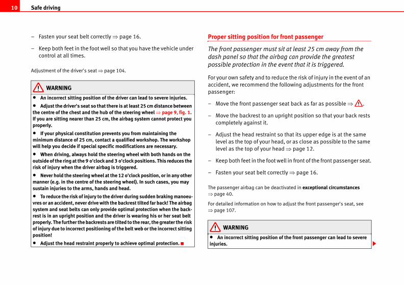
int so that its upper edge is at the same
head, or as close as possible to the same
r head ⇒ fig. 2.
n upright position so that your back rests
Fig. 2 Proper head restraint position for driver
st Operating instructions Tips and Maintenance
– When travelling long distances, take breaks regularly - at least
every two hours.
– If possible, avoid driving when you are tired or are under pres-
sure of time.
WARNING
When driving safety is impaired during a trip, the risk of injury and acci-dents increases.
Proper sitting position for occupants
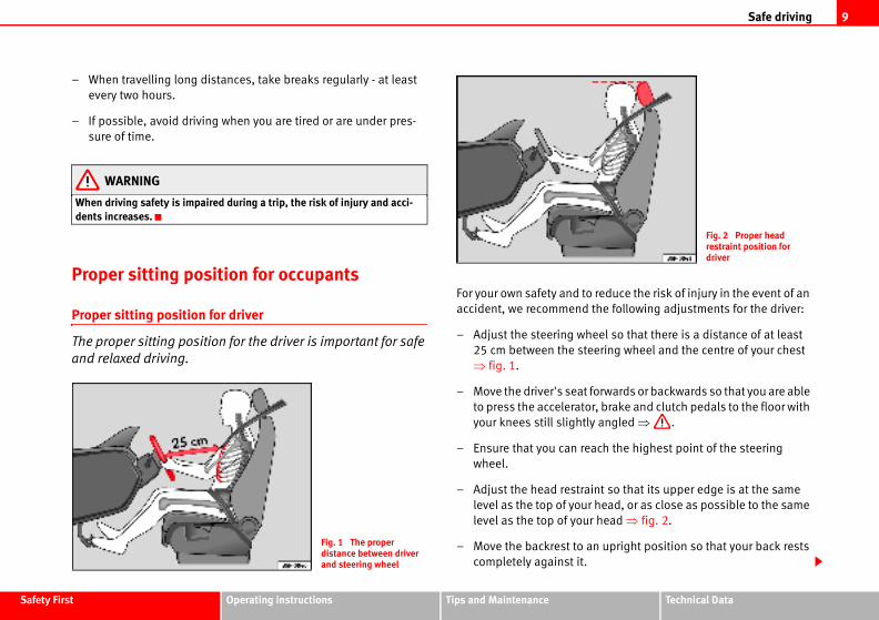
Proper sitting position for driver
The proper sitting position for the driver is important for safe
and relaxed driving.
For your own safety and to
accident, we recommend
– Adjust the steering wh
25 cm between the ste
⇒ fig. 1.
– Move the driver's seat
to press the accelerato
your knees still slightl
– Ensure that you can re
wheel.
– Adjust the head restra
level as the top of your
level as the top of you
– Move the backrest to a
completely against it.
Fig. 1 The proper distance between driver and steering wheel
Safe driving10
for front passenger
st sit at least 25 cm away from the
irbag can provide the greatest
e event that it is triggered.
reduce the risk of injury in the event of an
he following adjustments for the front
er seat back as far as possible ⇒ .
upright position so that your back rests
nt so that its upper edge is at the same
head, or as close as possible to the same
head ⇒ page 12.
ot well in front of the front passenger seat.
rrectly ⇒ page 16.
deactivated in exceptional circumstances
w to adjust the front passenger's seat, see
ion of the front passenger can lead to severe
– Fasten your seat belt correctly ⇒ page 16.
– Keep both feet in the foot well so that you have the vehicle under
control at all times.
Adjustment of the driver's seat ⇒ page 104.
WARNING
• An incorrect sitting position of the driver can lead to severe injuries.
• Adjust the driver's seat so that there is at least 25 cm distance between the centre of the chest and the hub of the steering wheel ⇒ page 9, fig. 1. If you are sitting nearer than 25 cm, the airbag system cannot protect you properly.
• If your physical constitution prevents you from maintaining the minimum distance of 25 cm, contact a qualified workshop. The workshop will help you decide if special specific modifications are necessary.
• When driving, always hold the steering wheel with both hands on the outside of the ring at the 9 o'clock and 3 o'clock positions. This reduces the risk of injury when the driver airbag is triggered.
• Never hold the steering wheel at the 12 o'clock position, or in any other manner (e.g. in the centre of the steering wheel). In such cases, you may sustain injuries to the arms, hands and head.
• To reduce the risk of injury to the driver during sudden braking manoeu-vres or an accident, never drive with the backrest tilted far back! The airbag system and seat belts can only provide optimal protection when the back-rest is in an upright position and the driver is wearing his or her seat belt properly. The further the backrests are tilted to the rear, the greater the risk of injury due to incorrect positioning of the belt web or the incorrect sitting position!
• Adjust the head restraint properly to achieve optimal protection.
Proper sitting position
The front passenger mu
dash panel so that the a
possible protection in th
For your own safety and to
accident, we recommend t
passenger:
– Move the front passeng
– Move the backrest to an
completely against it.
– Adjust the head restrai
level as the top of your
level as the top of your
– Keep both feet in the fo
– Fasten your seat belt co
The passenger airbag can be
⇒ page 40.
For detailed information on ho
⇒ page 107.
WARNING
• An incorrect sitting positinjuries.
Safe driving 11
Safety Fir Technical Data
the correct position ⇒ page 12.
oot well in front of the rear seat.
orrectly ⇒ page 16.
ld restraint system when you take children
42.
rear seat are not sitting properly, they could
t properly to achieve maximum protection.
de optimal protection when backrests are in an sengers are wearing their seat belts properly. t are not sitting in an upright position, the risk
sitioning of the belt web increases.
st Operating instructions Tips and Maintenance
• Adjust the front passenger seat so that there is at least 25 cm between your breastbone and the dash panel. If you are sitting nearer than 25 cm, the airbag system cannot protect you properly.
• If your physical constitution prevents you from maintaining the minimum distance of 25 cm, contact a qualified workshop. The workshop will help you decide if special specific modifications are necessary.
• Always keep your feet in the foot well when the vehicle is moving; never rest them on the instrument panel, out the window or on the seat. An incor-rect sitting position exposes you to an increased risk of injury in the event of a braking manoeuvre or an accident. If the airbag is triggered, you could sustain severe injuries due to an incorrect sitting position.
• To reduce the risk of injury to the front passenger during sudden braking manoeuvres or an accident, never travel with the backrest tilted far back! The airbag system and seat belts can only provide optimal protection when the backrest is in an upright position and the front passenger is wearing his or her seat belt properly. The further the backrests are tilted to the rear, the greater the risk of injury due to incorrect positioning of the belt web or the incorrect sitting position!
• Adjust the head restraint properly to achieve maximum protection.
Correct sitting position for passengers in the rear seats
Passengers in the rear seats must sit up straight, keep their
feet in the footwells, have the rear central head restraint posi-
tioned for use and wear their seat belts properly.
To reduce the risk of injury in the event of a sudden braking
manoeuvre or an accident, passengers on the rear bench seat must
observe the following:
– Adjust the headrest to
– Keep both feet in the f
– Fasten your seat belt c
– Use an appropriate chi
in the vehicle ⇒ page
WARNING
• If the passengers on thesustain severe injuries.
• Adjust the head restrain
• Seat belts can only proviupright position and the pasIf passengers on the rear seaof injury due to incorrect po
WARNING (continued)
Safe driving12
roperly to achieve maximum protection.
nt so that its upper edge is at the same
head, or as close as possible to the same
head and, at the very least, at eye level
⇒ page 105.
estraints removed or improperly adjusted njuries.
restraints could result in death in the event of
restraints also increase the risk of injury driving or braking manoeuvres.
always be adjusted according to the occu-
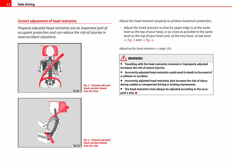
Correct adjustment of head restraints
Properly adjusted head restraints are an important part of
occupant protection and can reduce the risk of injuries in
most accident situations.
Adjust the head restraint p
– Adjust the head restrai
level as the top of your
level as the top of your
⇒ fig. 3 and ⇒ fig. 4.
Adjusting the head restraints
WARNING
• Travelling with the head rincreases the risk of severe i
• Incorrectly adjusted heada collision or accident.
• Incorrectly adjusted headduring sudden or unexpected
• The head restraints mustpant's size.
Fig. 3 Properly adjusted head restraint viewed from the front
Fig. 4 Properly adjusted head restraint viewed from the side
Safe driving 13
Safety Fir Technical Data
adjustment of the head restraints.
itting positions
ition can lead to severe injuries to
timal protection only when the belt webs
ncorrect sitting positions substantially
tion of seat belts and increase the risk of
t web position. As the driver, you are
occupants, especially children.
o assume an incorrect sitting position in
lling ⇒ .
amples of sitting positions that could be
The list is not complete, but we would like to
.
icle is in motion:
,
r to the rear,
sh panel,
h,
e of a seat,
st Operating instructions Tips and Maintenance
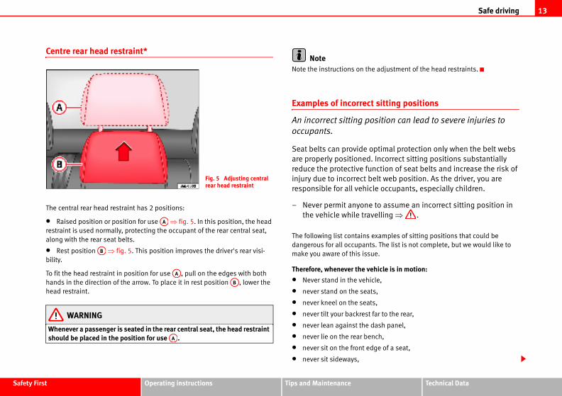
Centre rear head restraint*
The central rear head restraint has 2 positions:
• Raised position or position for use ⇒ fig. 5. In this position, the head
restraint is used normally, protecting the occupant of the rear central seat,
along with the rear seat belts.
• Rest position ⇒ fig. 5. This position improves the driver's rear visi-
bility.
To fit the head restraint in position for use , pull on the edges with both
hands in the direction of the arrow. To place it in rest position , lower the
head restraint.
WARNING
Whenever a passenger is seated in the rear central seat, the head restraint should be placed in the position for use .
NoteNote the instructions on the
Examples of incorrect s
An incorrect sitting pos
occupants.
Seat belts can provide op
are properly positioned. I
reduce the protective func
injury due to incorrect bel
responsible for all vehicle
– Never permit anyone t
the vehicle while trave
The following list contains ex
dangerous for all occupants.
make you aware of this issue
Therefore, whenever the veh
• Never stand in the vehicle
• never stand on the seats,
• never kneel on the seats,
• never tilt your backrest fa
• never lean against the da
• never lie on the rear benc
• never sit on the front edg
• never sit sideways,
Fig. 5 Adjusting central rear head restraint
AA
AB
AA
AB
AA
Safe driving14
can return unimpaired to their initial posi-
e the pedal area free and can be securely
e pedal must be free to move further than
hicle to a stop.
ort your feet properly and give you a good feel
on can lead to critical situations while driving.
driver foot well. An object could move into the operation. In the event of a sudden driving or not be able to operate the brake, clutch or ident!
r side
used which can be securely fastened
ot impair operation of the pedals.
ats are securely fastened during the trip
pedals ⇒ .
ve the pedals clear and which are secured to
ou can obtain suitable floor mats from a quali-
• never lean out of a window,
• never put your feet out of a window,
• never put your feet on the dash panel,
• never put your feet on the surface of a seat,
• never travel in a foot well,
• never travel on a seat without wearing the seat belt,
• never carry any person in the luggage compartment.
WARNING
• Every incorrect sitting position increases the risk of severe injuries.
• Sitting in an incorrect position exposes the occupants to severe injuries if airbags deploy, striking an occupant who has assumed an incorrect sitting position.
• Before the vehicle moves, assume the proper sitting position and main-tain it throughout the trip. Before every trip, instruct your passengers to assume the proper sitting position and to maintain it during the trip ⇒ page 9, “Proper sitting position for occupants”.
Pedal area
Pedals
The operation and freedom of movement of all pedals must
never be impaired by objects or floor mats.
– Ensure that you can always press the accelerator, brake and
clutch pedals unimpaired to the floor.
– Ensure that the pedals
tions.
Use only floor mats which leav
fastened in the foot well.
If a brake circuit fails, the brak
normal in order to bring the ve
Wear suitable shoes
Always wear shoes which supp
for the pedals.
WARNING
• Restricting pedal operati
• Never place objects in thepedal area and impair pedal braking manoeuvre, you will accelerator pedal. Risk of acc
Floor mats on the drive
Only floor mats may be
in the foot well and do n
– Ensure that the floor m
and do not obstruct the
Only use floor mats which lea
prevent them from slipping. Y
fied dealership.
Safe driving 15
Safety Fir Technical Data
e luggage compartment.
res or accidents, loose objects can be thrown upants or even to third parties. This increased increased if a loose object is struck by an ens, objects can be transformed into ry.
tre of gravity may shift when transporting ct the vehicle's handling and lead to an acci-
ial to adjust your speed and driving style nts.
d axle loads or allowed maximum weight. If the wed total weight is exceeded, the driving char-y change, leading to accidents, injuries and
unattended, especially when the tailgate is nto the luggage compartment closing the door in trapped without help and there is a mortal
lay in or around the vehicle. Close and lock doors when you leave the vehicle. Before you that there are no adults or children in the
ers in the luggage compartment. Every belted in ⇒ page 16.
cle helps reduce fogging of the windows. Used
on slits in the side trim of the luggage compart-
tion slits are never covered.
st Operating instructions Tips and Maintenance
WARNING
• If the pedals are obstructed, you could cause an accident. Risk of serious injuries.
• Ensure that the floor mats are always securely attached.
• Never lay or fit floor mats or other floor coverings over the original floor mats. This would reduce the pedal area and could obstruct the pedals. Risk of accident.
Stowing luggage
Loading the luggage compartment
All luggage and other loose objects must be safely secured in
the luggage compartment.
Unsecured objects which shift back and forth could affect safety or
driving characteristics of the vehicle by shifting the centre of gravity.
– Distribute the load evenly in the luggage compartment.
– Lay and stow heavy luggage as far forward as possible in the
luggage compartment.
– Stow heavy luggage as low as possible in the luggage compart-
ment.
WARNING
• Loose luggage and other objects in the luggage compartment can cause serious injuries.
• Always put objects in th
• During sudden manoeuvforward, injuring vehicle occrisk of injury will be further inflating airbag. If this happ“missiles”. Risk of fatal inju
• Please note that the cenheavy objects; this may affedent. Therefore, it is essentaccordingly, to avoid accide
• Never exceed the alloweallowed axle load or the alloacteristics of the vehicle madamage to the vehicle.
• Never leave your vehicleopen. Children could climb ibehind them; they will remarisk.
• Never allow children to pboth the tailgate and all thelock the vehicle, make sure vehicle.
• Never transport passengpassenger must be properly
Note• Air circulation in the vehi
air escapes through ventilati
ment. Ensure that the ventila
WARNING (continued)
Seat belts16
ple than there are seats available in the
icle must properly fasten and wear the seat eat. Children must be protected with an appro-
*
s a reminder to the driver to fasten
:
securely.
s to fasten their seat belts properly before
g child seats of the correct height for the
mbi-instrument lights up if the driver seat belt
ion is switched on. In addition, an acoustic
couple of seconds.
t go out until the driver seat belt is fastened
on.
Seat belts
Introduction
Before driving: remember your seat belt!
Properly worn seat belts can save lives!
In this chapter you will learn why seat belts are so important, how
they work and how to properly fasten, adjust and wear them.
– Read and observe all the information as well as the warnings in
this chapter.
WARNING
• If the seat belts are worn incorrectly or not at all, the risk of severe inju-ries increases.
• Properly worn seat belts can reduce severe injuries in the event of sudden braking manoeuvres or accidents. Therefore, you and your passen-gers should always wear the seat belts properly as long as the vehicle is in motion.
• Pregnant women or persons with physical disabilities must also use seat belts. Like all other occupants, these persons can also sustain severe injuries if they are not wearing their seat belts properly.
Number of seats
Your vehicle has five passenger places, two individual front seats and three
places on the rear seat. Each seat is equipped with a three-point seat belt.
WARNING
• Never transport more peovehicle.
• Every occupant in the vehbelt belonging to his or her spriate child restraint system.
Seat belt warning lamp
The warning lamp acts a
the seat belt.
Before starting the vehicle
– Fasten your safety belt
– Instruct your passenger
driving off.
– Protect children by usin
age of the child.
The warning lamp in the co
is not fastened when the ignit
signal can also be heard for a
The warning lamp* does no
while the ignition is switched
Seat belts 17
Safety Fir Technical Data
aws of physics work in the case of a head-on
rts moving ⇒ fig. 6 there is a certain amount of
rgy”, both in the vehicle and in the occupants.
y” depends on the speed of the vehicle and the
sengers. The higher the speed and the greater
there is to be “released” in an accident.
owever, is the speed of the vehicle. If the speed
km/h, for example, the kinetic energy increases
ur example are not restrained by seat belts, the
gy has to be absorbed at the point of impact
50 km/h, the forces acting on bodies in a colli-
nne (1,000 kg). At greater speed these forces
belts are not “attached” to the vehicle. In a
inue to move forward at the speed their vehicle
Fig. 7 The vehicle hits the wall: the occupants are not wearing seatbelts
st Operating instructions Tips and Maintenance
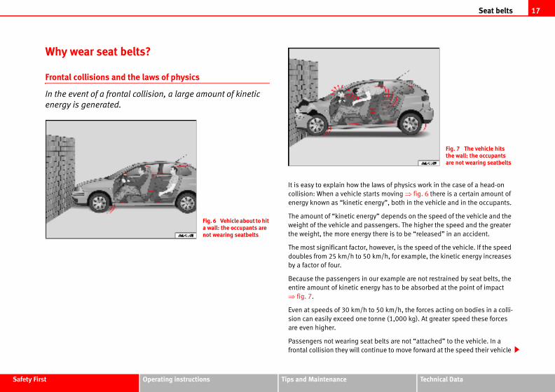
Why wear seat belts?
Frontal collisions and the laws of physics
In the event of a frontal collision, a large amount of kinetic
energy is generated.
It is easy to explain how the l
collision: When a vehicle sta
energy known as “kinetic ene
The amount of “kinetic energ
weight of the vehicle and pas
the weight, the more energy
The most significant factor, h
doubles from 25 km/h to 50
by a factor of four.
Because the passengers in o
entire amount of kinetic ener
⇒ fig. 7.
Even at speeds of 30 km/h to
sion can easily exceed one to
are even higher.
Passengers not wearing seat
frontal collision they will cont
Fig. 6 Vehicle about to hit a wall: the occupants are not wearing seatbelts
Seat belts18
acting on the body in a collision are so great
oneself with one's hands. In a frontal collision,
wn forward and will make violent contact with
, windscreen or whatever else is in the way
stitute for the seat belts. When deployed,
al protection. All occupants (including the
elts properly during the trip. This will reduce
e event of an accident – regardless of whether
.
ered only once. To achieve the best possible
always be worn properly so that you will be
h no airbag is deployed.
passengers to wear seat belts properly, as they
ward violently in an accident. Rear passengers
anger not only themselves but also the front
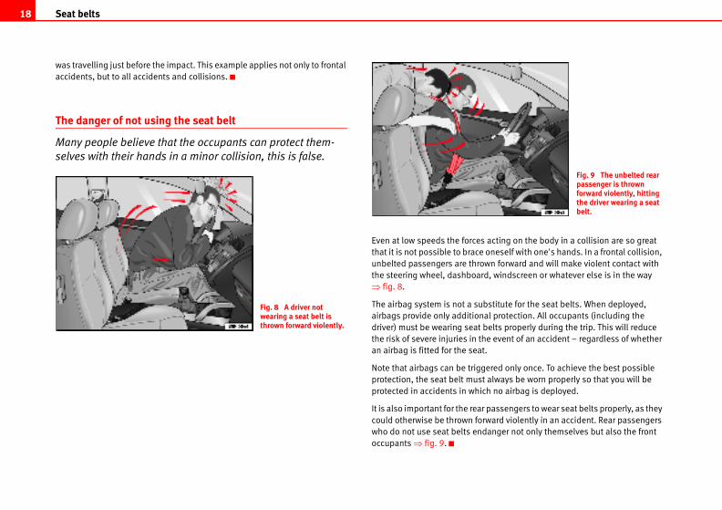
Fig. 9 The unbelted rear passenger is thrown forward violently, hitting the driver wearing a seat belt.
was travelling just before the impact. This example applies not only to frontal
accidents, but to all accidents and collisions.
The danger of not using the seat belt
Many people believe that the occupants can protect them-
selves with their hands in a minor collision, this is false.
Even at low speeds the forces
that it is not possible to brace
unbelted passengers are thro
the steering wheel, dashboard
⇒ fig. 8.
The airbag system is not a sub
airbags provide only addition
driver) must be wearing seat b
the risk of severe injuries in th
an airbag is fitted for the seat
Note that airbags can be trigg
protection, the seat belt must
protected in accidents in whic
It is also important for the rear
could otherwise be thrown for
who do not use seat belts end
occupants ⇒ fig. 9.
Fig. 8 A driver not wearing a seat belt is thrown forward violently.
Seat belts 19
Safety Fir Technical Data
n seat belts before every trip, even when "just
wear their seat belts as well. Accident statistics
at belts to be an effective means of substantially
d improving the chances of survival in a serious
rly worn seat belts improve the protection
ent of an accident. For this reason, wearing a
most countries.
ipped with airbags, the seat belts must be
airbags, for example, are only triggered in some
irbags will not be triggered during minor frontal
ns, rear collisions, rolls or accidents in which the
e control unit is not exceeded.
wear your seat belt and ensure that your
eir seat belts properly before you drive off!
seat belts
rrectly, they can reduce the risk of
elt as described in this booklet.
lts can be fastened at all times and are not
incorrectly or not at all, the risk of severe inju-rotection from seat belts can be achieved only
st Operating instructions Tips and Maintenance
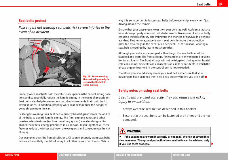
Seat belts protect
Passengers not wearing seat belts risk severe injuries in the
event of an accident.
Properly worn seat belts hold the vehicle occupants in the correct sitting posi-
tions and substantially reduce the kinetic energy in the event of an accident.
Seat belts also help to prevent uncontrolled movements that could lead to
severe injuries. In addition, properly worn seat belts reduce the danger of
being thrown from the car.
Passengers wearing their seat belts correctly benefit greatly from the ability
of the belts to absorb kinetic energy. The front crumple zones and other
passive safety features (such as the airbag system) are also designed to
absorb the kinetic energy generated in a collision. Taken together, all these
features reduce the forces acting on the occupants and consequently the risk
of injury.
Our examples describe frontal collisions. Of course, properly worn seat belts
reduce substantially the risk of injury in all other types of accidents. This is
why it is so important to faste
driving around the corner".
Ensure that your passengers
have shown properly worn se
reducing the risk of injury an
accident. Furthermore, prope
provided by airbags in the ev
seat belt is required by law in
Although your vehicle is equ
fastened and worn. The front
frontal accidents. The front a
collisions, minor side collisio
airbag trigger threshold in th
Therefore, you should always
passengers have fastened th
Safety notes on using
If seat belts are used co
injury in an accident.
– Always wear the seat b
– Ensure that the seat be
damaged.
WARNING
• If the seat belts are wornries increases. The optimal pif you use them properly.
Fig. 10 Driver wearing the seat belt properly: is secured by the belt in sharp braking
Seat belts20
damaged seat belt yourself. The seat belts ified in any way.
ean, otherwise the retractors may not work
nt and rear occupants are locked into
its full protection if the belt web is not
Fig. 11 Belt buckle and latch plate of seat belt
• Fasten your seat belt before every trip - even when driving in town. That applies also to your front and rear passengers – danger of injury!
• The seat belt cannot offer its full protection if the belt web is not posi-tioned correctly.
• Never allow two passengers (even children) to share the same seat belt.
• Keep both feet in the foot-well in front of your seat as long as the vehicle is in motion.
• Never unbuckle a seat belt while the vehicle is in motion. Risk of fatal injury.
• The belt webbing must never be twisted while it is being worn.
• The belt webbing should never lie on hard or fragile objects (such as glasses or pens, etc.) because this can cause injuries.
• Do not allow the seat belt to be damaged or jammed, or to rub on any sharp edges.
• Never wear the seat belt under the arm or in any other incorrect posi-tion.
• Loose, bulky clothing (such as an overcoat over a jacket) impairs the proper fit and function of the belts, reducing their capacity to protect.
• The slot in the seat belt buckle must not be blocked with paper or other objects, as this can prevent the latch plate from engaging securely.
• Never use seat belt clips, retaining rings or similar instruments to alter the position of the belt webbing.
• Frayed or torn seat belts or damage to the connections, belt retractors or parts of the buckle could cause severe injuries in the event of an acci-dent. Therefore, you must check the condition of all seat belts at regular intervals.
• Seat belts which have been worn in an accident and stretched must be replaced by a qualified workshop. Renewal may be necessary even if there is no apparent damage. The belt anchorage should also be checked.
• Do not attempt to repair amust not be removed or mod
• The belts must be kept clproperly.
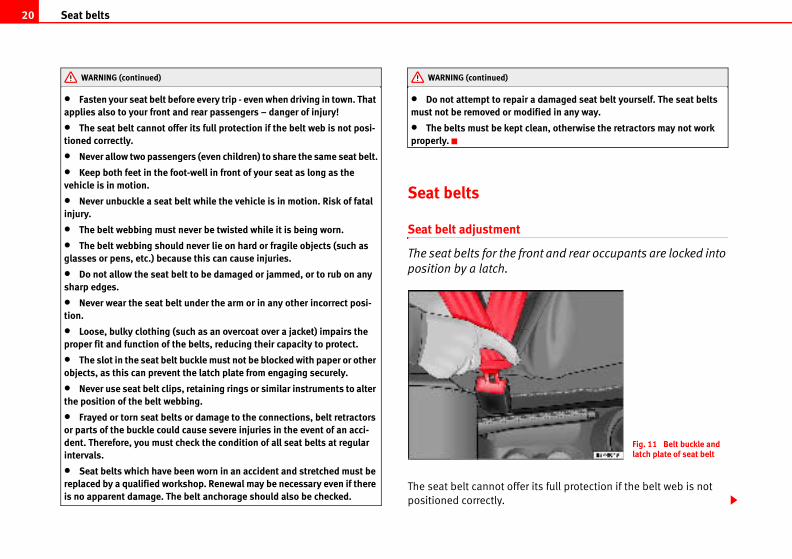
Seat belts
Seat belt adjustment
The seat belts for the fro
position by a latch.
The seat belt cannot offer
positioned correctly.
WARNING (continued) WARNING (continued)
Seat belts 21
Safety Fir Technical Data
ximum protection only when they are
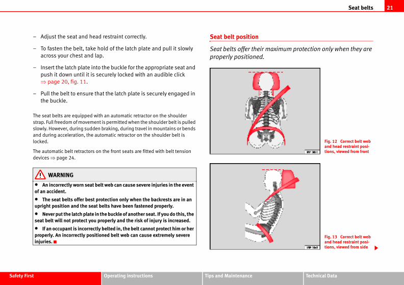
Fig. 12 Correct belt web and head restraint posi-tions, viewed from front
Fig. 13 Correct belt web and head restraint posi-tions, viewed from side
st Operating instructions Tips and Maintenance
– Adjust the seat and head restraint correctly.
– To fasten the belt, take hold of the latch plate and pull it slowly
across your chest and lap.
– Insert the latch plate into the buckle for the appropriate seat and
push it down until it is securely locked with an audible click
⇒ page 20, fig. 11.
– Pull the belt to ensure that the latch plate is securely engaged in
the buckle.
The seat belts are equipped with an automatic retractor on the shoulder
strap. Full freedom of movement is permitted when the shoulder belt is pulled
slowly. However, during sudden braking, during travel in mountains or bends
and during acceleration, the automatic retractor on the shoulder belt is
locked.
The automatic belt retractors on the front seats are fitted with belt tension
devices ⇒ page 24.
WARNING
• An incorrectly worn seat belt web can cause severe injuries in the event of an accident.
• The seat belts offer best protection only when the backrests are in an upright position and the seat belts have been fastened properly.
• Never put the latch plate in the buckle of another seat. If you do this, the seat belt will not protect you properly and the risk of injury is increased.
• If an occupant is incorrectly belted in, the belt cannot protect him or her properly. An incorrectly positioned belt web can cause extremely severe injuries.
Seat belt position
Seat belts offer their ma
properly positioned.
Seat belts22
imum protection only when the belt web
age 21.
d head restraint correctly.
pull the belt evenly across your chest and
the pelvis ⇒ fig. 14.
to the buckle for the corresponding seat
it is securely locked with an audible click
hat the latch plate is securely engaged in
elt web can cause severe injuries in the event
lap part of the seat belt must lie as low as er across the stomach, and always lie flat so n the abdomen.
rnings ⇒ page 19.
WARNING
• An incorrectly worn seat belt web can cause severe injuries in the event of an accident.
• The shoulder belt must be positioned around the middle of the shoulder. The seat belt must lie flat and snugly on the torso ⇒ page 21, fig. 12.
• The lap part of the seat belt must lie across the pelvis, never across the stomach. The seat belt must lie flat and snugly on the pelvis ⇒ page 21, fig. 13. Pull the belt tight if necessary to take up any slack.
• Read and observe the warnings ⇒ page 19.
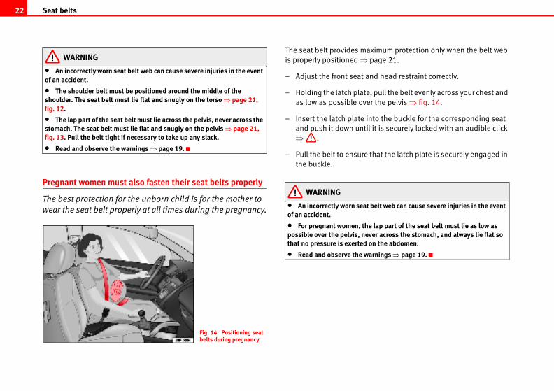
Pregnant women must also fasten their seat belts properly
The best protection for the unborn child is for the mother to
wear the seat belt properly at all times during the pregnancy.
The seat belt provides max
is properly positioned ⇒ p
– Adjust the front seat an
– Holding the latch plate,
as low as possible over
– Insert the latch plate in
and push it down until
⇒ .
– Pull the belt to ensure t
the buckle.
WARNING
• An incorrectly worn seat bof an accident.
• For pregnant women, thepossible over the pelvis, nevthat no pressure is exerted o
• Read and observe the wa
Fig. 14 Positioning seat belts during pregnancy
Seat belts 23
Safety Fir Technical Data
height
ers can be used to adjust the position
houlder.
the front seats can be used to adjust the
shoulder.
the shoulder belt guide and hold it in this
t guide up or down until you have adjusted
rect position.
e shoulder belt sharply to check that the
belt guide is engaged securely.
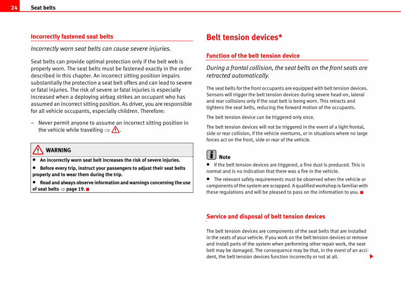
Fig. 16 Location of the belt height adjuster
st Operating instructions Tips and Maintenance
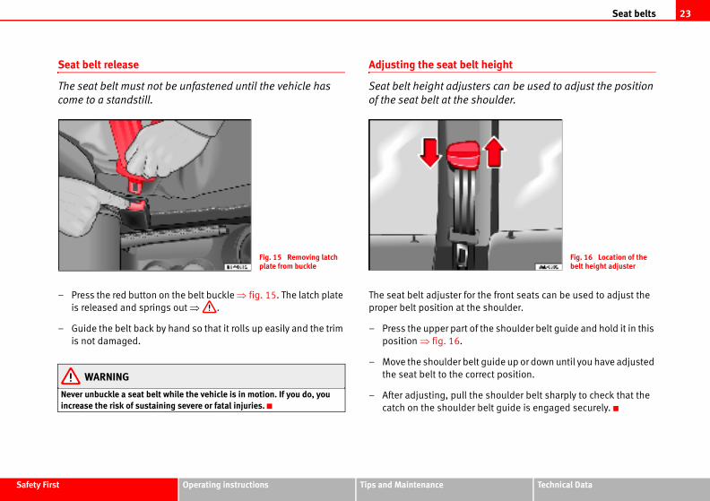
Seat belt release
The seat belt must not be unfastened until the vehicle has
come to a standstill.
– Press the red button on the belt buckle ⇒ fig. 15. The latch plate
is released and springs out ⇒ .
– Guide the belt back by hand so that it rolls up easily and the trim
is not damaged.
WARNING
Never unbuckle a seat belt while the vehicle is in motion. If you do, you increase the risk of sustaining severe or fatal injuries.
Adjusting the seat belt
Seat belt height adjust
of the seat belt at the s
The seat belt adjuster for
proper belt position at the
– Press the upper part of
position ⇒ fig. 16.
– Move the shoulder bel
the seat belt to the cor
– After adjusting, pull th
catch on the shoulder
Fig. 15 Removing latch plate from buckle
Seat belts24
es*
sion device
, the seat belts on the front seats are
upants are equipped with belt tension devices.
nsion devices during severe head-on, lateral
seat belt is being worn. This retracts and
ing the forward motion of the occupants.
triggered only once.
ot be triggered in the event of a light frontal,
hicle overturns, or in situations where no large
rear of the vehicle.
are triggered, a fine dust is produced. This is
at there was a fire in the vehicle.
ments must be observed when the vehicle or
scrapped. A qualified workshop is familiar with
pleased to pass on the information to you.
belt tension devices
omponents of the seat belts that are installed
you work on the belt tension devices or remove
when performing other repair work, the seat
nsequence may be that, in the event of an acci-
function incorrectly or not at all.
Incorrectly fastened seat belts
Incorrectly worn seat belts can cause severe injuries.
Seat belts can provide optimal protection only if the belt web is
properly worn. The seat belts must be fastened exactly in the order
described in this chapter. An incorrect sitting position impairs
substantially the protection a seat belt offers and can lead to severe
or fatal injuries. The risk of severe or fatal injuries is especially
increased when a deploying airbag strikes an occupant who has
assumed an incorrect sitting position. As driver, you are responsible
for all vehicle occupants, especially children. Therefore:
– Never permit anyone to assume an incorrect sitting position in
the vehicle while travelling ⇒ .
WARNING
• An incorrectly worn seat belt increases the risk of severe injuries.
• Before every trip, instruct your passengers to adjust their seat belts properly and to wear them during the trip.
• Read and always observe information and warnings concerning the use of seat belts ⇒ page 19.
Belt tension devic
Function of the belt ten
During a frontal collision
retracted automatically.
The seat belts for the front occ
Sensors will trigger the belt te
and rear collisions only if the
tightens the seat belts, reduc
The belt tension device can be
The belt tension devices will n
side or rear collision, if the ve
forces act on the front, side or
Note• If the belt tension devices
normal and is no indication th
• The relevant safety require
components of the system are
these regulations and will be
Service and disposal of
The belt tension devices are c
in the seats of your vehicle. If
and install parts of the system
belt may be damaged. The co
dent, the belt tension devices
Seat belts 25
Safety Fir Technical Data
st Operating instructions Tips and MaintenanceSo that the effectiveness of the belt tension device is not reduced and that
removed parts do not cause any injuries or environmental pollution, regula-
tions, which are known to the qualified workshops, must be observed.
WARNING
• If repairs are not carried out by a professional, or if the belt tension devices are used incorrectly, the risk of severe or fatal injuries increases. The belt tension devices may fail to trigger or may trigger in the wrong circumstances.
• Never attempt to repair, adjust, remove or install parts of the belt tension devices or seat belts.
• The belt tension device and seat belt including its automatic retractor cannot be repaired.
• Any work on the belt tension devices and seat belts, including the removal and refitting of system parts in conjunction with other repair work, must be performed by a qualified workshop only.
• The belt tension devices will only provide protection for one accident and must be changed it they have been activated.
Airbag system26
g may inflict critical or fatal injuries upon the
larly to children.
possible distance between yourself and the
t airbags can completely deploy when trig-
m protection.
at will trigger an airbag are: the type of acci-
d the speed of the vehicle.
ered depends primarily on the vehicle deceler-
ollision and detected by the control unit. If the
during the collision and measured by the
specified reference values, the front, side
be triggered. Take into account that the visible
an accident, for whatever reason, are not an
gs were triggered.
orrectly or assuming an incorrect sitting posi-al injuries.
hildren, who are not properly belted can s if the airbag is triggered. You should always years of age on the rear seat. Never transport are not restrained or the restraint system is
, size or weight.
eat belt or if you lean forward or to the side or osition, the risk of injury is increased risk of injury will be further increased if you ag.
y from an inflating airbag, always wear the
Airbag system
Brief introduction
Why wear a seat belt and assume the correct sitting position?
For the inflating airbags to achieve the best protection, the
seat belt must always be worn properly and the correct sitting
position must be assumed.
For your own safety and the safety of the passengers, please ensure
the following before you drive:
– Always wear the seat belt properly.
– Adjust the driver seat and the steering wheel correctly.
– Adjust the front passenger seat correctly.
– Adjust the head restraint seat correctly ⇒ page 12.
– Use the correct child restraint system to protect children in your
vehicle.
The airbag deploys in fractions of a second and with a high velocity. If you
have assumed an incorrect seating position at that moment, you could
sustain critical injuries. Therefore, it is essential that all occupants maintain
a correct sitting position while travelling.
Braking heavily the moment before an accident may cause an occupant not
wearing a seat belt to be thrown forward into the area of the deploying airbag.
In this case, the inflating airba
occupant. This applies particu
Always maintain the greatest
front airbag. This way, the fron
gered, providing their maximu
The most important factors th
dent, the angle of collision an
Whether the airbags are trigg
ation rate resulting from the c
vehicle deceleration occurring
control unit remains below the
and/or curtain airbag will not
damage in a vehicle following
indication as to why the airba
WARNING
• Wearing the seat belt inction can lead to critical or fat
• All occupants, including csustain critical or fatal injurietransport all children up to 12children in the vehicle if theynot appropriate for their age
• If you are not wearing a sassume an incorrect sitting psubstantially. This increasedare struck by an inflating airb
• To reduce the risk of injurseat belt properly.
Airbag system 27
Safety Fir Technical Data
ger airbag can strike the rear-facing child seat gainst the door, the roof or the backrest.
tances, it should be necessary to transport a at on the front passenger seat, it is absolutely he following safety measures:
enger airbag ⇒ page 40, “Deactivating
e approved by the child seat manufacturer for r seat with front or side airbag.
instructions of the child seat manufacturer all warnings
ling the child seat, push the front passenger ar so that the greatest possible distance to the s ensured.
s prevent the front passenger seat from being .
ont passenger seat must be in an upright
g and belt tension device system
itors the airbag and belt tension
ll airbags and belt tension devices in the
its and wiring connections.
st Operating instructions Tips and Maintenance
• Always properly adjust the front seats.
The danger of fitting a child seat on the front passenger seat
Rear-facing child seats must never be used on the front
passenger seat when the front passenger airbag is enabled.
An enabled front airbag on the front passenger side is potentially a major
danger to a child. The front passenger seat is life threatening to a child if you
transport the child in a rear-facing child seat. You should always transport all
children up to 12 years of age on the rear seat.
If a rear-facing child seat is secured to the front passenger seat, an inflating
airbag can strike it with such great force that critical or fatal injuries may
result.
Therefore we urgently recommend that you transport children on the rear
seats. That is the safest place in the vehicle for children. Alternatively, the
front passenger airbag can be disabled with a key-operated switch
⇒ page 40. When transporting children, use a child seat appropriate to the
age and size of each child.
For those vehicles that do not include a key lock switch to turn the airbag off,
an Authorised Service Centre must be consulted.
WARNING
• If a child seat is secured to the front passenger seat, the risk to the child of sustaining critical or fatal injuries in the event of an accident increases.
• Never secure a rear-facing child seat to the front passenger seat if the front passenger airbag is enabled. The child can suffer critical or fatal inju-ries when the front passenger airbag is triggered.
• An inflating front passenand hurl it with great force a
• If, under special circumschild in a rear-facing child seessential that you observe t
− Disable the front passairbags*”.
− The child seat must buse on a front passenge
− Follow the installationand absolutely observe
− Before properly instalseat all the way to the refront passenger airbag i
− Ensure that no objectpushed completely back
− The backrest of the frposition.
Warning lamp for airba
This warning lamp mon
device system.
The warning lamp monitors a
vehicle, including control un
WARNING (continued) WARNING (continued)
Airbag system28
ay be that, in the event of an accident, the
oes not inflate at all.
nts must be observed when the vehicle or
scrapped. The specialist workshops and the
miliar with these requirements.
ut by a professional, or if the airbags are used or fatal injuries is increased. The airbags may in the wrong circumstances.
hing on the steering wheel hub or the soft unit on the passenger side of the dashboard, y them in any way.
ch any objects such as cup holders or tele-aces covering the airbag units.
el or dash panel, you may use only a dry cloth Never clean the dash panel and surface of the s containing solvents. Solvents cause the the airbag inflates, disintegrating plastic njuries.
djust, remove or install parts of the airbag
stem or removal and installation of the airbag (such as repairs to the steering wheel) should fied workshop. Qualified workshops have the
ation and qualified personnel.
hat you go to a qualified workshop for all work
front bumper or the body.
ction for one accident only, if they have been ced.
Monitoring of airbag and belt tension device system
The functionality of the airbag and belt tension device system is constantly
monitored electronically. The warning lamp will light up for a few seconds
every time the ignition is switched on (self-diagnosis).
The system must be checked when the warning lamp :
• does not come on when the ignition is switched on,
• does not go out about 4 seconds after the ignition is switched on,
• goes out and then comes on again after the ignition is switched on,
• or if it comes on or flickers while the car is moving.
In the event of a malfunction, the warning lamp remains on continuously.
Have the airbag system inspected immediately by a qualified workshop.
If any of the airbags are de-activated by the Authorised Service Centre, the
indicator lights for several seconds more after the verification and will turn off
if there is no fault.
WARNING
• If there is a malfunction, the airbag and belt tension device system cannot properly perform its protective function.
• If a malfunction should occur, have the system checked immediately by a qualified workshop. Otherwise there is a risk that, in the event of an acci-dent, the airbag system and belt tension devices may not be triggered, or may not be triggered correctly.
Repair, care and disposal of the airbags
The parts of the airbag system are installed in various places in your vehicle.
If you work on the airbag system or remove and install parts of the system
when performing other repair work, parts of the airbag system may be
damaged. The consequence m
airbag inflates incorrectly or d
The relevant safety requireme
components of the airbag are
Vehicle disposal centres are fa
WARNING
• If repairs are not carried oincorrectly, the risk of severefail to inflate, or could inflate
• Do not cover or stick anytplastic surface of the airbag and do not obstruct or modif
• It is important not to attaphone mountings to the surf
• To clean the steering wheor one moistened with water.airbag module with cleansersurface to become porous. Ifparts can cause substantial i
• Never attempt to repair, asystem.
• Any work on the airbag sycomponents for other repairsbe performed only by a qualinecessary tools, repair inform
• We urgently recommend ton the airbag system.
• Never attempt to alter the
• The airbags provide protedeployed they must be repla
Airbag system 29
Safety Fir Technical Data
r is located in the steering wheel ⇒ fig. 17 and
nger is located in the dash panel ⇒ fig. 18.
text “AIRBAG”.
elts, the front airbag system gives the front
ion for the head and chest in the event of a
ge 32, “Safety notes on front airbag system”.
nction of restraining the occupants, the seat
front passenger in a position where the airbags
tion in a frontal collision.
bstitute for seat belts, but is an integral part of
safety system. Please bear in mind that the
ffectively when the occupants are wearing their
adjusted the head restraints properly. For this
o wear the seat belts at all times, not only
w in most countries, but also for your safety.
irbag system are:
monitoring system (control unit),
ag with gas generator) for the driver and front
dash panel insert ⇒ page 27.
g system is monitored electronically. The airbag
r a few seconds every time the ignition is
if the warning lamp
he ignition is switched on ⇒ page 27,
econds after the ignition is switched on,
on again after the ignition is switched on,
s while the car is moving.
st Operating instructions Tips and Maintenance
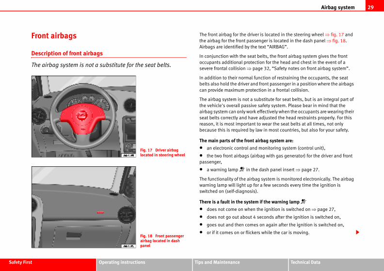
Front airbags
Description of front airbags
The airbag system is not a substitute for the seat belts.
The front airbag for the drive
the airbag for the front passe
Airbags are identified by the
In conjunction with the seat b
occupants additional protect
severe frontal collision ⇒ pa
In addition to their normal fu
belts also hold the driver and
can provide maximum protec
The airbag system is not a su
the vehicle's overall passive
airbag system can only work e
seat belts correctly and have
reason, it is most important t
because this is required by la
The main parts of the front a
• an electronic control and
• the two front airbags (airb
passenger,
• a warning lamp in the
The functionality of the airba
warning lamp will light up fo
switched on (self-diagnosis).
There is a fault in the system
• does not come on when t
• does not go out about 4 s
• goes out and then comes
• or if it comes on or flicker
Fig. 17 Driver airbag located in steering wheel
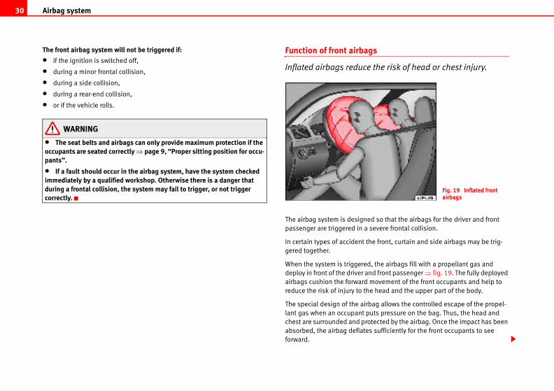
Fig. 18 Front passenger airbag located in dash panel
Airbag system30
s
the risk of head or chest injury.
so that the airbags for the driver and front
evere frontal collision.
e front, curtain and side airbags may be trig-
the airbags fill with a propellant gas and
d front passenger ⇒ fig. 19. The fully deployed
ovement of the front occupants and help to
head and the upper part of the body.
ag allows the controlled escape of the propel-
ts pressure on the bag. Thus, the head and
ected by the airbag. Once the impact has been
sufficiently for the front occupants to see
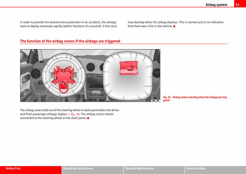
Fig. 19 Inflated front airbags
The front airbag system will not be triggered if:
• if the ignition is switched off,
• during a minor frontal collision,
• during a side collision,
• during a rear-end collision,
• or if the vehicle rolls.
WARNING
• The seat belts and airbags can only provide maximum protection if the occupants are seated correctly ⇒ page 9, “Proper sitting position for occu-pants”.
• If a fault should occur in the airbag system, have the system checked immediately by a qualified workshop. Otherwise there is a danger that during a frontal collision, the system may fail to trigger, or not trigger correctly.
Function of front airbag
Inflated airbags reduce
The airbag system is designed
passenger are triggered in a s
In certain types of accident th
gered together.
When the system is triggered,
deploy in front of the driver an
airbags cushion the forward m
reduce the risk of injury to the
The special design of the airb
lant gas when an occupant pu
chest are surrounded and prot
absorbed, the airbag deflates
forward.
Airbag system 31
Safety Fir Technical Data
deploys. This is normal and is no indication
hicle.
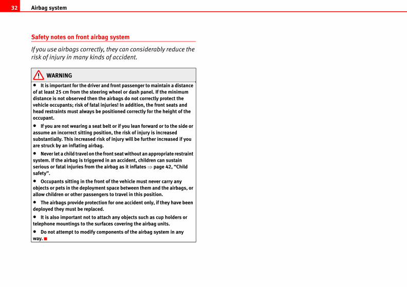
g. 20 Airbag covers reacting when the airbags are trig-red
st Operating instructions Tips and Maintenance
In order to provide the desired extra protection in an accident, the airbags
have to deploy extremely rapidly (within fractions of a second). A fine dust
may develop when the airbag
that there was a fire in the ve
The function of the airbag covers if the airbags are triggered
The airbag covers fold out of the steering wheel or dash panel when the driver
and front passenger airbags deploy ⇒ fig. 20. The airbag covers remain
connected to the steering wheel or the dash panel.
Fige
Airbag system32
Safety notes on front airbag system
If you use airbags correctly, they can considerably reduce the
risk of injury in many kinds of accident.
WARNING
• It is important for the driver and front passenger to maintain a distance of at least 25 cm from the steering wheel or dash panel. If the minimum distance is not observed then the airbags do not correctly protect the vehicle occupants; risk of fatal injuries! In addition, the front seats and head restraints must always be positioned correctly for the height of the occupant.
• If you are not wearing a seat belt or if you lean forward or to the side or assume an incorrect sitting position, the risk of injury is increased substantially. This increased risk of injury will be further increased if you are struck by an inflating airbag.
• Never let a child travel on the front seat without an appropriate restraint system. If the airbag is triggered in an accident, children can sustain serious or fatal injuries from the airbag as it inflates ⇒ page 42, “Child safety”.
• Occupants sitting in the front of the vehicle must never carry any objects or pets in the deployment space between them and the airbags, or allow children or other passengers to travel in this position.
• The airbags provide protection for one accident only, if they have been deployed they must be replaced.
• It is also important not to attach any objects such as cup holders or telephone mountings to the surfaces covering the airbag units.
• Do not attempt to modify components of the airbag system in any way.
Airbag system 33
Safety Fir Technical Data
bstitute for seat belts, but is an integral part of
safety system. Please bear in mind that the
ffectively when the occupants are wearing their
is most important to wear the seat belts at all
s required by law in most countries, but also for
ot be triggered
off,
ion,
n,
system are
monitoring system (control unit),
es of the backrests of the front seats,
dash panel insert ⇒ page 27.
g system is monitored electronically. The airbag
r approx. 4 seconds every time the ignition is
e side airbags will not work, if the sensors do ressure increase on the interior of the doors, the areas with holes or openings in the door
f the interior panels have been removed.
r door panels have been removed or if the tly fitted.
st Operating instructions Tips and Maintenance
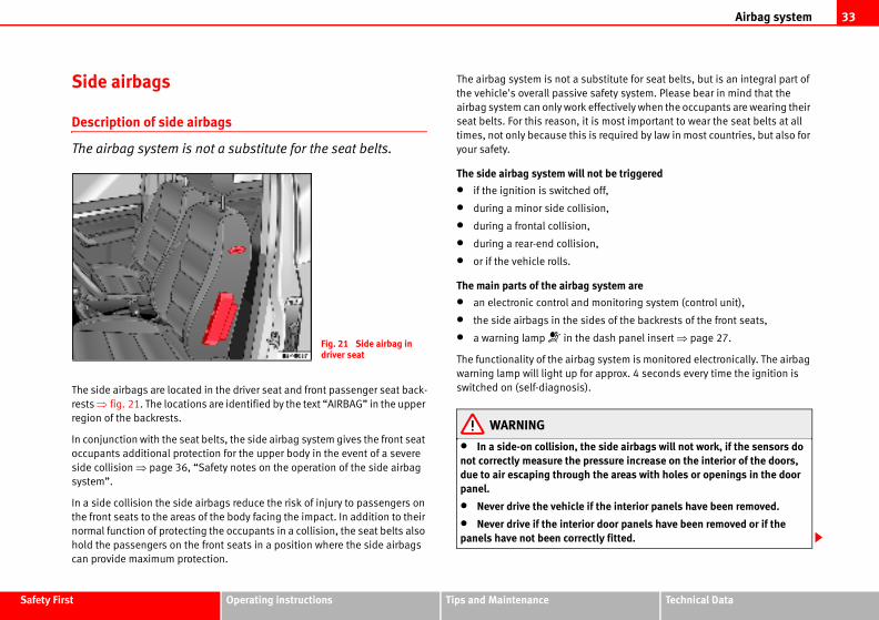
Side airbags
Description of side airbags
The airbag system is not a substitute for the seat belts.
The side airbags are located in the driver seat and front passenger seat back-
rests ⇒ fig. 21. The locations are identified by the text “AIRBAG” in the upper
region of the backrests.
In conjunction with the seat belts, the side airbag system gives the front seat
occupants additional protection for the upper body in the event of a severe
side collision ⇒ page 36, “Safety notes on the operation of the side airbag
system”.
In a side collision the side airbags reduce the risk of injury to passengers on
the front seats to the areas of the body facing the impact. In addition to their
normal function of protecting the occupants in a collision, the seat belts also
hold the passengers on the front seats in a position where the side airbags
can provide maximum protection.
The airbag system is not a su
the vehicle's overall passive
airbag system can only work e
seat belts. For this reason, it
times, not only because this i
your safety.
The side airbag system will n
• if the ignition is switched
• during a minor side collis
• during a frontal collision,
• during a rear-end collisio
• or if the vehicle rolls.
The main parts of the airbag
• an electronic control and
• the side airbags in the sid
• a warning lamp in the
The functionality of the airba
warning lamp will light up fo
switched on (self-diagnosis).
WARNING
• In a side-on collision, thnot correctly measure the pdue to air escaping throughpanel.
• Never drive the vehicle i
• Never drive if the interiopanels have not been correc
Fig. 21 Side airbag in driver seat
Airbag system34
uce the risk of head or chest injury in
ions.
e airbag is triggered on the impact side of the
e front, curtain and side airbags may be trig-
the airbag is filled with propellant gas.
extra protection in an accident, the airbags
dly (within fractions of a second). A fine dust
deploys. This is normal and is no indication
icle.
hion the movement of the occupants of the
the risk of injury to the upper body.
Fig. 22 Inflated side airbag on left side of vehicle
• Never drive the vehicle if the loudspeakers in the door panels have been removed, unless the holes left by the loudspeakers have been correctly closed.
• Always check that the openings are closed or covered if loudspeakers or other equipment are fitted in the interior door panels.
• Any work carried out to the doors should be made in a qualified author-ised workshop.
• The seat belts and airbags can only provide maximum protection if the occupants are seated correctly ⇒ page 9, “Proper sitting position for occu-pants”.
• If a fault should occur in the airbag system, have the system checked immediately by a qualified workshop. Otherwise there is a danger that during a side collision, the system may fail to trigger, or not trigger correctly.
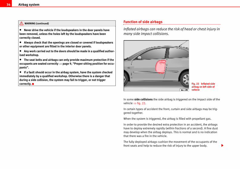
Function of side airbags
Inflated airbags can red
many side impact collis
In some side collisions the sid
vehicle ⇒ fig. 22.
In certain types of accident th
gered together.
When the system is triggered,
In order to provide the desired
have to deploy extremely rapi
may develop when the airbag
that there was a fire in the veh
The fully deployed airbags cus
front seats and help to reduce
WARNING (continued)
Airbag system 35
Safety Fir Technical Data
st Operating instructions Tips and MaintenanceThe special design of the airbag allows the controlled escape of the propel-
lant gas when an occupant puts pressure on the bag. Thus, the head and
chest are surrounded and protected by the airbag.
Airbag system36
incorrect sitting position, they expose them-f injury in the event of an accident. This is ild is travelling on the front passenger seat gered in an accident; this could have critical us injury or death ⇒ page 42, “Child safety”.
ag system or removal and installation of the repairs (such as removal of the front seat) a qualified workshop. Otherwise, a fault may tion of the airbag system.
components of the airbag system in any way.
s are managed through sensors located in the ensure the correct functioning of the side and rs nor the door panels should be modified in kers). If the front door is damaged in any way,
orking of the system. All work carried out on in a qualified workshop.
Safety notes on the operation of the side airbag system
If airbags are used correctly, they can considerably reduce the
risk of injury in side impact collisions.
WARNING
• If you do not wear a seat belt, if you lean forward, or are not seated correctly while the vehicle is in motion, you are at greater risk of injury should the side airbag system be triggered in an accident.
• In order for the side airbags to provide their maximum protection, the prescribed sitting position must always be maintained with seat belts fastened while travelling.
• Occupants of the outer seats must never carry any objects or pets in the deployment space between them and the airbags, or allow children or other passengers to travel in this position. It is also important not to attach any accessories (such as cup holders) to the doors. This would impair the protection offered by the side airbags.
• The built-in coat hooks should be used only for lightweight clothing. Do not leave any heavy or sharp-edged objects in the pockets.
• Great forces, such as hard blows or kicks, must not be exerted upon the backrest bolster because the system may be damaged. In this case the side airbags would not be triggered.
• Under no circumstances should protective covers be fitted over the driver seat or front passenger seat unless the covers have been expressly approved for use in your vehicle. Because the airbag deploys from the side of the backrest, the use of conventional seat covers would obstruct the side airbag, seriously reducing the airbag's effectiveness.
• Any damage to the original seat upholstery or around the seams of the side airbag units must be repaired immediately by a qualified workshop.
• The airbags provide protection for one accident only, if they have been deployed they must be replaced.
• When children assume anselves to an increased risk oparticularly the case if the chand the airbag system is trigconsequences including serio
• Any work on the side airbairbag components for othershould only be performed bybe introduced into the opera
• Do not attempt to modify
• The side and head airbaginterior of the front doors. Tohead airbags neither the dooany way (e.g. fitting loudspeathis may affect the correct wthe front door must be made
WARNING (continued)
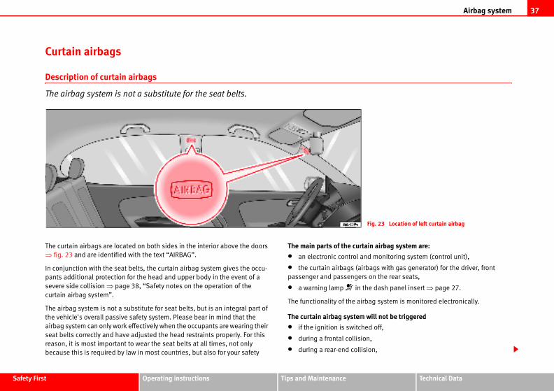
Airbag system 37
Safety Fir Technical Data
airbag system are:
monitoring system (control unit),
gs with gas generator) for the driver, front
n the rear seats,
dash panel insert ⇒ page 27.
g system is monitored electronically.
ll not be triggered
off,
n,
g. 23 Location of left curtain airbag
st Operating instructions Tips and Maintenance
Curtain airbags
Description of curtain airbags
The airbag system is not a substitute for the seat belts.
The curtain airbags are located on both sides in the interior above the doors
⇒ fig. 23 and are identified with the text “AIRBAG”.
In conjunction with the seat belts, the curtain airbag system gives the occu-
pants additional protection for the head and upper body in the event of a
severe side collision ⇒ page 38, “Safety notes on the operation of the
curtain airbag system”.
The airbag system is not a substitute for seat belts, but is an integral part of
the vehicle's overall passive safety system. Please bear in mind that the
airbag system can only work effectively when the occupants are wearing their
seat belts correctly and have adjusted the head restraints properly. For this
reason, it is most important to wear the seat belts at all times, not only
because this is required by law in most countries, but also for your safety
The main parts of the curtain
• an electronic control and
• the curtain airbags (airba
passenger and passengers o
• a warning lamp in the
The functionality of the airba
The curtain airbag system wi
• if the ignition is switched
• during a frontal collision,
• during a rear-end collisio
Fi
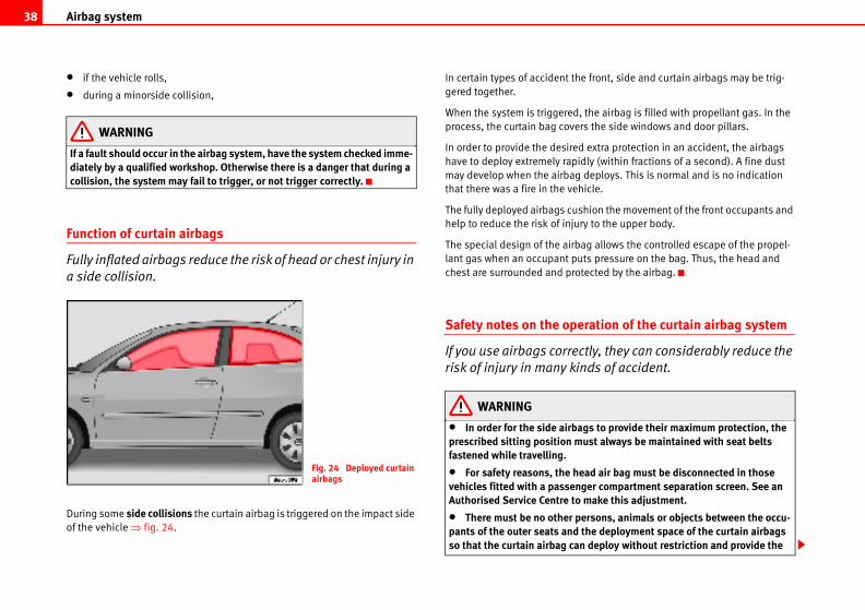
Airbag system38
e front, side and curtain airbags may be trig-
the airbag is filled with propellant gas. In the
rs the side windows and door pillars.
extra protection in an accident, the airbags
dly (within fractions of a second). A fine dust
deploys. This is normal and is no indication
icle.
hion the movement of the front occupants and
ry to the upper body.
ag allows the controlled escape of the propel-
ts pressure on the bag. Thus, the head and
tected by the airbag.
ration of the curtain airbag system
tly, they can considerably reduce the
ds of accident.
gs to provide their maximum protection, the ust always be maintained with seat belts
ad air bag must be disconnected in those ger compartment separation screen. See an make this adjustment.
ersons, animals or objects between the occu-the deployment space of the curtain airbags deploy without restriction and provide the
• if the vehicle rolls,
• during a minorside collision,
WARNING
If a fault should occur in the airbag system, have the system checked imme-diately by a qualified workshop. Otherwise there is a danger that during a collision, the system may fail to trigger, or not trigger correctly.
Function of curtain airbags
Fully inflated airbags reduce the risk of head or chest injury in
a side collision.
During some side collisions the curtain airbag is triggered on the impact side
of the vehicle ⇒ fig. 24.
In certain types of accident th
gered together.
When the system is triggered,
process, the curtain bag cove
In order to provide the desired
have to deploy extremely rapi
may develop when the airbag
that there was a fire in the veh
The fully deployed airbags cus
help to reduce the risk of inju
The special design of the airb
lant gas when an occupant pu
chest are surrounded and pro
Safety notes on the ope
If you use airbags correc
risk of injury in many kin
WARNING
• In order for the side airbaprescribed sitting position mfastened while travelling.
• For safety reasons, the hevehicles fitted with a passenAuthorised Service Centre to
• There must be no other ppants of the outer seats and so that the curtain airbag can
Fig. 24 Deployed curtain airbags
Airbag system 39
Safety Fir Technical Data
st Operating instructions Tips and Maintenancegreatest possible protection. Therefore, sun blinds which have not been expressly approved for use in your vehicle may not be attached to the side windows.
• The built-in coat hooks should be used only for lightweight clothing. Do not leave any heavy or sharp-edged objects in the pockets. When using the coat hooks, do not hang the clothes on coat hangers.
• The airbags provide protection for one accident only, if they have been deployed they must be replaced.
• Any work on the curtain airbag system or removal and installation of the airbag components for other repairs (such as removal of the roof lining) should only be performed by a qualified workshop. Otherwise, a fault may be introduced into the operation of the airbag system.
• Do not attempt to modify components of the airbag system in any way.
• The side and head airbags are managed through sensors located in the interior of the front doors. To ensure the correct functioning of the side and head airbags neither the doors nor the door panels should be modified in any way (e.g. fitting loudspeakers). If the front door is damaged in any way, this may affect the correct working of the system. All work carried out on the front door must be made in a qualified workshop.
WARNING (continued)
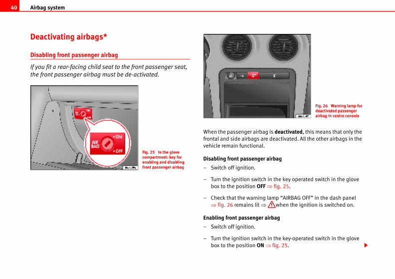
Airbag system40
g is deactivated, this means that only the
e deactivated. All the other airbags in the
airbag
in the key operated switch in the glove
⇒ fig. 25.
lamp “AIRBAG OFF” in the dash panel
when the ignition is switched on.
irbag
in the key-operated switch in the glove
⇒ fig. 25.
Fig. 26 Warning lamp for deactivated passenger airbag in centre console
Deactivating airbags*
Disabling front passenger airbag
If you fit a rear-facing child seat to the front passenger seat,
the front passenger airbag must be de-activated.
When the passenger airba
frontal and side airbags ar
vehicle remain functional.
Disabling front passenger
– Switch off ignition.
– Turn the ignition switch
box to the position OFF
– Check that the warning
⇒ fig. 26 remains lit ⇒
Enabling front passenger a
– Switch off ignition.
– Turn the ignition switch
box to the position ON
Fig. 25 In the glove compartment: key for enabling and disabling front passenger airbag
Airbag system 41
Safety Fir Technical Data
er the front passenger airbag will deploy m your passengers of this.
key to activate / deactivate the passenger enger frontal and side airbag will be activated
irbag on the passenger side will remain
st Operating instructions Tips and Maintenance
– Check that the warning lamp “AIRBAG OFF” in the dash panel
does ⇒ page 40, fig. 26 not light up when the ignition is
switched on ⇒ .
WARNING
• The driver is responsible for the proper position of the key-operated switch.
• You should deactivate the front passenger airbag only if you have to use a rear-facing child seat in exceptional cases. ⇒ page 42, “Child safety”.
• Never install a child seat facing backwards (or rear-facing) on the front passenger seat unless the front passenger airbag has been disabled. This represents a risk of fatal injuries to the child! However, if it is necessary in exceptional circumstances to transport a child in a rear-facing child seat on the front passenger seat, you must always disable the front passenger airbag.
• As soon as the child seat is no longer needed on the front passenger seat, enable the front passenger airbag again.
• Only deactivate the passenger airbag when the ignition is off, other-wise a fault may occur in the airbag system, this will create a danger that in case of an accident, the airbag does not deploy properly or does not deploy at all.
• When the passenger airbag is deactivated, if the warning lamp AIRBAG OFF is not continuously lit up when the front passenger airbag is disabled, there may be a fault in the airbag system:
− Have the airbag system inspected immediately by a qualified work-shop.
− Do not use a child seat on the front passenger seat! The front passenger airbag could be triggered despite the fact that there is a fault in the system and, as a result, a child could sustain serious or fatal inju-ries.
− It is not certain whethduring an accident! Infor
• When using the ignitionfrontal airbag, only the pass/ deactivated. The curtain aactive.
WARNING (continued)
Child safety42
de the manufacturer's directions for child seat
lways keep them in the vehicle.
Child safety
Brief introduction
Introduction
Statistics show that children are generally safer on the rear
seat than on the front passenger seat.
We recommend that children under 12 years of age be transported on the rear
seats. Children travelling on the rear seat must use a child restraint system or
the seat belts provided, depending on their age, height and weight. For
safety reasons, the child restraint system should be installed in the centre of
the rear seat or behind the front passenger's seat.
The physical principles involved and the forces acting in a collision apply to
children just as much as adults ⇒ page 17, “Why wear seat belts?”. But
unlike adults, children do not have fully developed muscle and bone struc-
tures. This means that children are subject to a greater risk of injury.
To reduce this risk, children must always use special child restraint systems
when travelling in the vehicle.
We recommend the use of child safety products from the SEAT Genuine Acces-
sories Program including systems for all ages made by “Peke”1).
These systems have been especially designed and approved, complying with
the ECE-R44. regulation.
Follow the manufacturer's instructions and observe any statutory require-
ments when installing and using child seats. Always read and observe
⇒ page 43, “Safety notes on using child seats”.
We recommend that you inclu
use in the vehicle wallet and a
1) Not for all countries
Child safety 43
Safety Fir Technical Data
bies on your lap, this can result in potentially
transported in a vehicle without being properly neel on a seat while travelling. In an accident, ugh the vehicle, causing possibly fatal injuries upants.
proper sitting position when the car is moving, greater risk of injury during a sudden braking . This is particularly the case if the child is trav-r seat and the airbag system is triggered in an nsequences including serious injury or death.
protect your child!
pervised in a child seat or alone in the vehicle.
nditions, it may become extremely hot or cold be fatal.
an 1.5 metres tall must not wear a normal seat t system, as this could cause injuries to the uring a sudden braking manoeuvre or in an
bbing to become twisted or jammed, or to rub
lts can cause injuries even in a minor collision res.
aximum protection only when the belt web is 20, “Seat belts”.
py a child seat ⇒ page 44, “Child seats”.
st Operating instructions Tips and Maintenance
Safety notes on using child seats
Proper use of child seats substantially reduces the risk of
injury in an accident!
As the driver, you are responsible for any children you transport in
your vehicle.
– Protect your children by properly using appropriate child seats
⇒ page 44.
– Always ensure that the belt webbing is properly positioned
according to the instructions provided by the manufacturer of the
child seat.
– When travelling, do not allow children to distract you from traffic.
– Take breaks regularly during long trips. Take a break at least
every two hours.
WARNING
• Never install a child seat facing backwards (or rear-facing) on the front passenger seat unless the front passenger airbag has been disabled. This could lead to a risk of potentially fatal injuries to the child! However, if it is necessary, in exceptional cases, to transport a child in the front passenger seat, the front passenger airbag must always be disabled ⇒ page 40, “Deactivating airbags*”. If the passenger seat has a height adjustment option, move it to the highest position.
• For those vehicles that do not include a key lock switch to turn the airbag off, an Authorised Service Centre must be consulted.
• All passengers, especially children, must assume the proper sitting position and be properly belted in while travelling.
• Never hold children or bafatal injuries to the child!
• Never allow a child to be secured, or to stand up or kthe child could be flung throto themselves and other occ
• If children assume an imthey expose themselves to manoeuvre or in an accidentelling on the front passengeaccident; this could have co
• A suitable child seat can
• Never leave a child unsu
• Depending on weather coinside the vehicle. This can
• Children who are less thbelt without a child restrainabdominal and neck areas daccident.
• Do not allow the belt weon any sharp edges.
• Incorrectly worn seat beor sudden braking manoeuv
• The seat belt provides mproperly positioned ⇒ page
• Only one child may occu
WARNING (continued)
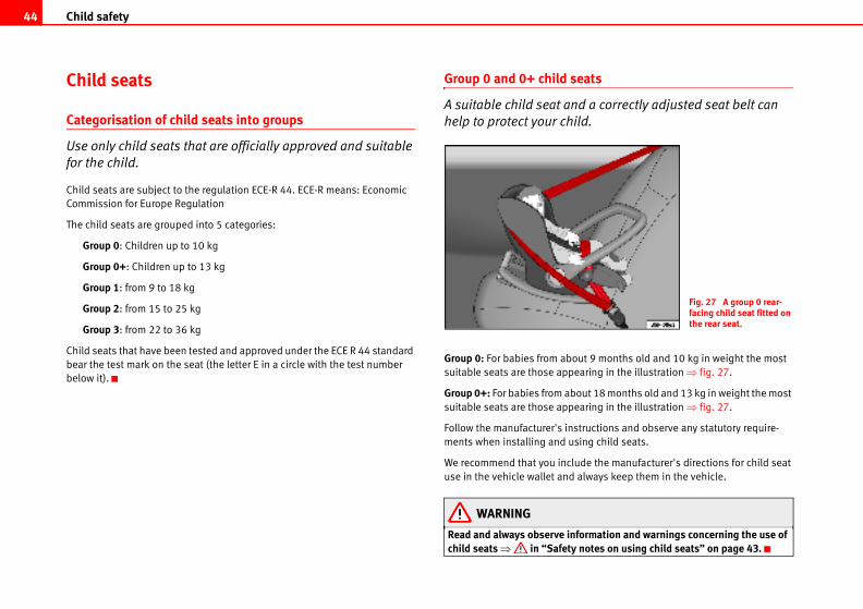
Child safety44
ats
a correctly adjusted seat belt can
d.
t 9 months old and 10 kg in weight the most
aring in the illustration ⇒ fig. 27.
ut 18 months old and 13 kg in weight the most
aring in the illustration ⇒ fig. 27.
tructions and observe any statutory require-
ing child seats.
de the manufacturer's directions for child seat
lways keep them in the vehicle.
ormation and warnings concerning the use of notes on using child seats” on page 43.
Fig. 27 A group 0 rear-facing child seat fitted on the rear seat.
Child seats
Categorisation of child seats into groups
Use only child seats that are officially approved and suitable
for the child.
Child seats are subject to the regulation ECE-R 44. ECE-R means: Economic
Commission for Europe Regulation
The child seats are grouped into 5 categories:
Group 0: Children up to 10 kg
Group 0+: Children up to 13 kg
Group 1: from 9 to 18 kg
Group 2: from 15 to 25 kg
Group 3: from 22 to 36 kg
Child seats that have been tested and approved under the ECE R 44 standard
bear the test mark on the seat (the letter E in a circle with the test number
below it).
Group 0 and 0+ child se
A suitable child seat and
help to protect your chil
Group 0: For babies from abou
suitable seats are those appe
Group 0+: For babies from abo
suitable seats are those appe
Follow the manufacturer's ins
ments when installing and us
We recommend that you inclu
use in the vehicle wallet and a
WARNING
Read and always observe infchild seats ⇒ in “Safety
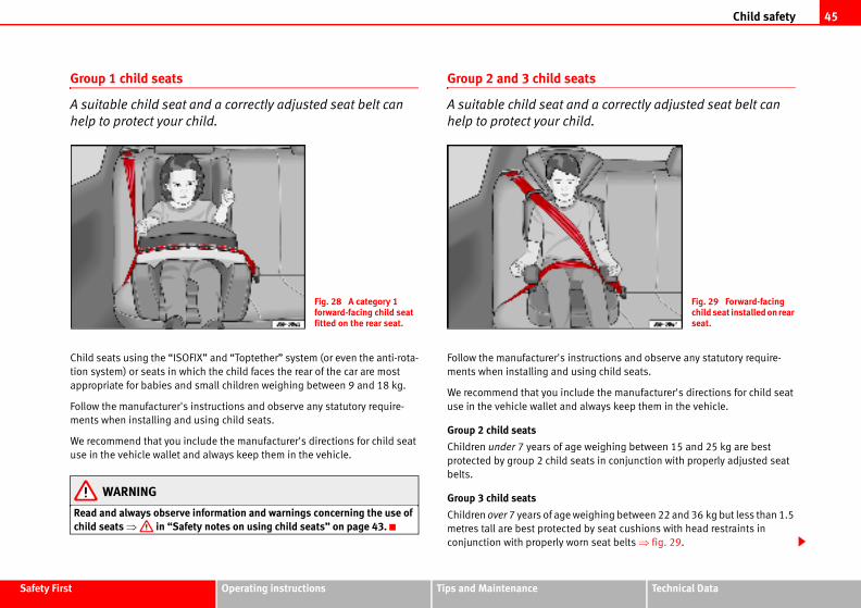
Child safety 45
Safety Fir Technical Data
ats
d a correctly adjusted seat belt can
ld.
tructions and observe any statutory require-
sing child seats.
ude the manufacturer's directions for child seat
always keep them in the vehicle.
weighing between 15 and 25 kg are best
ats in conjunction with properly adjusted seat
eighing between 22 and 36 kg but less than 1.5
by seat cushions with head restraints in
rn seat belts ⇒ fig. 29.
Fig. 29 Forward-facing child seat installed on rear seat.
st Operating instructions Tips and Maintenance
Group 1 child seats
A suitable child seat and a correctly adjusted seat belt can
help to protect your child.
Child seats using the “ISOFIX” and “Toptether” system (or even the anti-rota-
tion system) or seats in which the child faces the rear of the car are most
appropriate for babies and small children weighing between 9 and 18 kg.
Follow the manufacturer's instructions and observe any statutory require-
ments when installing and using child seats.
We recommend that you include the manufacturer's directions for child seat
use in the vehicle wallet and always keep them in the vehicle.
WARNING
Read and always observe information and warnings concerning the use of child seats ⇒ in “Safety notes on using child seats” on page 43.
Group 2 and 3 child se
A suitable child seat an
help to protect your chi
Follow the manufacturer's ins
ments when installing and u
We recommend that you incl
use in the vehicle wallet and
Group 2 child seats
Children under 7 years of age
protected by group 2 child se
belts.
Group 3 child seats
Children over 7 years of age w
metres tall are best protected
conjunction with properly wo
Fig. 28 A category 1 forward-facing child seat fitted on the rear seat.
Child safety46
WARNING
• The shoulder part of the seat belt must lie approximately on the centre of the shoulder, never across the neck or the arm. The seat belt must lie close to the torso. The lap belt part must lie across the pelvis, not across the stomach, and always fit closely. Pull the belt tight if necessary to take up any slack ⇒ page 20, “Seat belts”.
• Read and always observe information and warnings concerning the use of child seats ⇒ in “Safety notes on using child seats” on page 43.
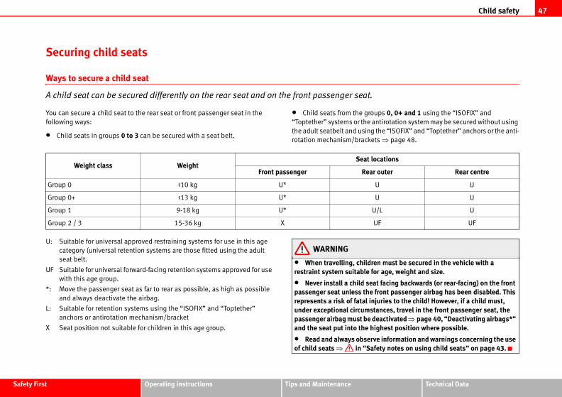
Child safety 47
Safety Fir Technical Data
ps 0, 0+ and 1 using the “ISOFIX” and
tirotation system may be secured without using
he “ISOFIX” and “Toptether” anchors or the anti-
s ⇒ page 48.
n must be secured in the vehicle with a r age, weight and size.
facing backwards (or rear-facing) on the front ront passenger airbag has been disabled. This uries to the child! However, if a child must, nces, travel in the front passenger seat, the activated ⇒ page 40, “Deactivating airbags*” hest position where possible.
information and warnings concerning the use ty notes on using child seats” on page 43.
cations
outer Rear centre
U
U
L U
F UF
st Operating instructions Tips and Maintenance
Securing child seats
Ways to secure a child seat
A child seat can be secured differently on the rear seat and on the front passenger seat.
You can secure a child seat to the rear seat or front passenger seat in the
following ways:
• Child seats in groups 0 to 3 can be secured with a seat belt.
• Child seats from the grou
“Toptether” systems or the an
the adult seatbelt and using t
rotation mechanism/bracket
U: Suitable for universal approved restraining systems for use in this age
category (universal retention systems are those fitted using the adult
seat belt.
UF Suitable for universal forward-facing retention systems approved for use
with this age group.
*: Move the passenger seat as far to rear as possible, as high as possible
and always deactivate the airbag.
L: Suitable for retention systems using the “ISOFIX” and “Toptether”
anchors or antirotation mechanism/bracket
X Seat position not suitable for children in this age group.
WARNING
• When travelling, childrerestraint system suitable fo
• Never install a child seatpassenger seat unless the frepresents a risk of fatal injunder exceptional circumstapassenger airbag must be deand the seat put into the hig
• Read and always observeof child seats ⇒ in “Safe
Weight class WeightSeat lo
Front passenger Rear
Group 0 <10 kg U* U
Group 0+ <13 kg U* U
Group 1 9-18 kg U* U/
Group 2 / 3 15-36 kg X U
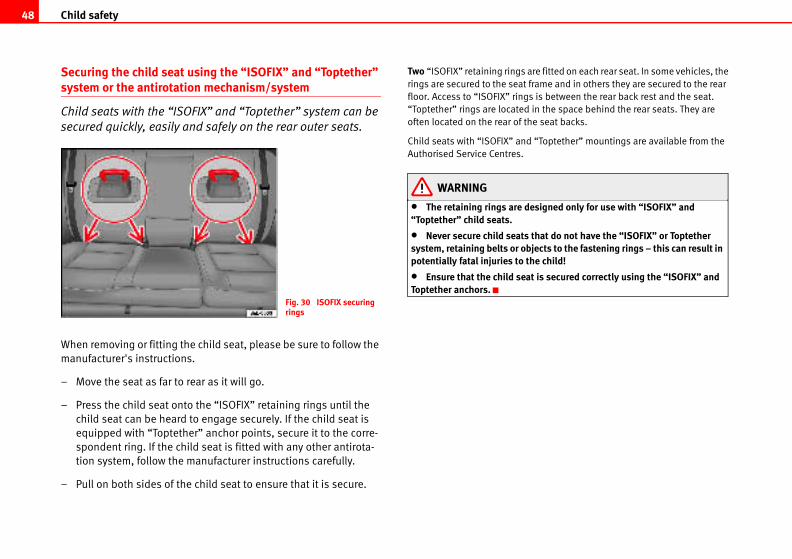
Child safety48
re fitted on each rear seat. In some vehicles, the
rame and in others they are secured to the rear
is between the rear back rest and the seat.
in the space behind the rear seats. They are
e seat backs.
“Toptether” mountings are available from the
signed only for use with “ISOFIX” and
that do not have the “ISOFIX” or Toptether jects to the fastening rings – this can result in e child!
t is secured correctly using the “ISOFIX” and
Securing the child seat using the “ISOFIX” and “Toptether” system or the antirotation mechanism/system
Child seats with the “ISOFIX” and “Toptether” system can be
secured quickly, easily and safely on the rear outer seats.
When removing or fitting the child seat, please be sure to follow the
manufacturer's instructions.
– Move the seat as far to rear as it will go.
– Press the child seat onto the “ISOFIX” retaining rings until the
child seat can be heard to engage securely. If the child seat is
equipped with “Toptether” anchor points, secure it to the corre-
spondent ring. If the child seat is fitted with any other antirota-
tion system, follow the manufacturer instructions carefully.
– Pull on both sides of the child seat to ensure that it is secure.
Two “ISOFIX” retaining rings a
rings are secured to the seat f
floor. Access to “ISOFIX” rings
“Toptether” rings are located
often located on the rear of th
Child seats with “ISOFIX” and
Authorised Service Centres.
WARNING
• The retaining rings are de“Toptether” child seats.
• Never secure child seats system, retaining belts or obpotentially fatal injuries to th
• Ensure that the child seaToptether anchors.
Fig. 30 ISOFIX securing rings

49
Safety Fir Technical Data
st Operating instructions Tips and Maintenance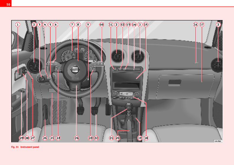
50
Fig. 3
1 Instrument panel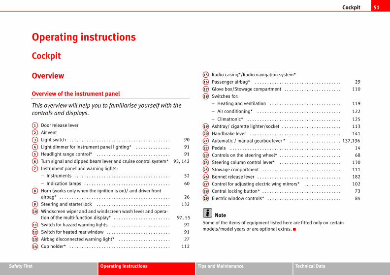
Cockpit 51
Safety Fir Technical Data
igation system*
. . . . . . . . . . . . . . . . . . . . . . . . . . . . . . . .
partment . . . . . . . . . . . . . . . . . . . . . . .
n . . . . . . . . . . . . . . . . . . . . . . . . . . . . .
. . . . . . . . . . . . . . . . . . . . . . . . . . . . . . . .
. . . . . . . . . . . . . . . . . . . . . . . . . . . . . . . .
r/socket . . . . . . . . . . . . . . . . . . . . . . . .
. . . . . . . . . . . . . . . . . . . . . . . . . . . . . . . .
rbox lever * . . . . . . . . . . . . . . . . . . . . .
. . . . . . . . . . . . . . . . . . . . . . . . . . . . . . . .
wheel* . . . . . . . . . . . . . . . . . . . . . . . . .
lever* . . . . . . . . . . . . . . . . . . . . . . . . .
. . . . . . . . . . . . . . . . . . . . . . . . . . . . . . . .
. . . . . . . . . . . . . . . . . . . . . . . . . . . . . . . .
ctric wing mirrors* . . . . . . . . . . . . . . .
. . . . . . . . . . . . . . . . . . . . . . . . . . . . . . . .
* . . . . . . . . . . . . . . . . . . . . . . . . . . . . . .
ent listed here are fitted only on certain
ptional extras.
29
110
119
122
125
113
141
137,136
14
68
130
111
182
102
73
84
st Operating instructions Tips and Maintenance
Operating instructions
Cockpit
Overview
Overview of the instrument panel
This overview will help you to familiarise yourself with the
controls and displays.
Door release lever
Air vent
Light switch . . . . . . . . . . . . . . . . . . . . . . . . . . . . . . . . . . . . . . . . .
Light dimmer for instrument panel lighting* . . . . . . . . . . . . . .
Headlight range control* . . . . . . . . . . . . . . . . . . . . . . . . . . . . . .
Turn signal and dipped beam lever and cruise control system*
Instrument panel and warning lights:
− Instruments . . . . . . . . . . . . . . . . . . . . . . . . . . . . . . . . . . . . . . .
− Indication lamps . . . . . . . . . . . . . . . . . . . . . . . . . . . . . . . . . . .
Horn (works only when the ignition is on)/ and driver front
airbag* . . . . . . . . . . . . . . . . . . . . . . . . . . . . . . . . . . . . . . . . . . . . .
Steering and starter lock . . . . . . . . . . . . . . . . . . . . . . . . . . . . . .
Windscreen wiper and and windscreen wash lever and opera-
tion of the multi-function display* . . . . . . . . . . . . . . . . . . . . . . .
Switch for hazard warning lights . . . . . . . . . . . . . . . . . . . . . . . .
Switch for heated rear window . . . . . . . . . . . . . . . . . . . . . . . . . .
Airbag disconnected warning light* . . . . . . . . . . . . . . . . . . . . .
Cup holder* . . . . . . . . . . . . . . . . . . . . . . . . . . . . . . . . . . . . . . . . .
Radio casing*/Radio nav
Passenger airbag* . . .
Glove box/Stowage com
Switches for:
− Heating and ventilatio
− Air conditioning* . .
− Climatronic* . . . . . .
Ashtray/ cigarette lighte
Handbrake lever . . . . .
Automatic / manual gea
Pedals . . . . . . . . . . . . .
Controls on the steering
Steering column control
Stowage compartment
Bonnet release lever . .
Control for adjusting ele
Central locking button*
Electric window controls
NoteSome of the items of equipm
models/model years or are o
A1
A2
A3 90
A4 91
A5 91
A6 93, 142
A7
52
60
A8
26
A9 132
A10
97, 55
A11 92
A12 91
A13 27
A14 112
A15
A16
A17
A18
A19
A20
A21
A22
A23
A24
A25
A26
A27
A28
A29
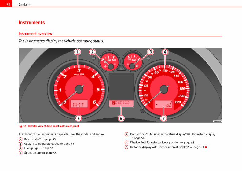
Cockpit52
perature display*/Multifunction display
ever position ⇒ page 58
vice interval display* ⇒ page 58
Instruments
Instrument overview
The instruments display the vehicle operating status.
Fig. 32 Detailed view of dash panel instrument panel
The layout of the instruments depends upon the model and engine.
Rev counter* ⇒ page 53
Coolant temperature gauge ⇒ page 53
Fuel gauge ⇒ page 54
Speedometer ⇒ page 54
Digital clock*/Outside tem
⇒ page 54
Display field for selector l
Distance display with ser
A1
A2
A3
A4
A5
A6
A7
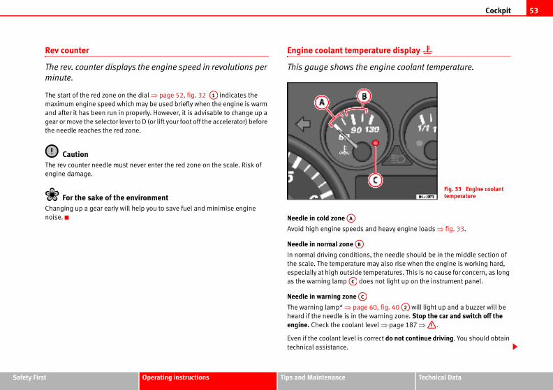
Cockpit 53
Safety Fir Technical Data
ature display
ngine coolant temperature.
d heavy engine loads ⇒ fig. 33.
the needle should be in the middle section of
ay also rise when the engine is working hard,
peratures. This is no cause for concern, as long
not light up on the instrument panel.
0, fig. 40 will light up and a buzzer will be
arning zone. Stop the car and switch off the el ⇒ page 187 ⇒ .
rrect do not continue driving. You should obtain
Fig. 33 Engine coolant temperature
A2
st Operating instructions Tips and Maintenance
Rev counter
The rev. counter displays the engine speed in revolutions per
minute.
The start of the red zone on the dial ⇒ page 52, fig. 32 indicates the
maximum engine speed which may be used briefly when the engine is warm
and after it has been run in properly. However, it is advisable to change up a
gear or move the selector lever to D (or lift your foot off the accelerator) before
the needle reaches the red zone.
CautionThe rev counter needle must never enter the red zone on the scale. Risk of
engine damage.
For the sake of the environmentChanging up a gear early will help you to save fuel and minimise engine
noise.
Engine coolant temper
This gauge shows the e
Needle in cold zone
Avoid high engine speeds an
Needle in normal zone
In normal driving conditions,
the scale. The temperature m
especially at high outside tem
as the warning lamp does
Needle in warning zone
The warning lamp* ⇒ page 6
heard if the needle is in the w
engine. Check the coolant lev
Even if the coolant level is co
technical assistance.
A1
AA
AB
AC
AC
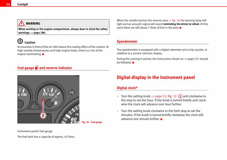
Cockpit54
reserve zone ⇒ fig. 34 the warning lamp will
ill sound reminding the driver to refuel. At this
res of fuel in the tank.
with a digital odometer and a trip counter, in
display.
the instructions shown on ⇒ page 151 should
the instrument panel
page 52, fig. 32 anti-clockwise to
r. If the knob is turned briefly anti-clock-
nce one hour further.
lockwise to the limit stop to set the
turned briefly clockwise the clock will
rther.
A5
WARNING
When working in the engine compartment, always bear in mind the safety warnings ⇒ page 180.
CautionAccessories in front of the air inlet reduce the cooling effect of the coolant. At
high outside temperatures and high engine loads, there is a risk of the
engine overheating.
Fuel gauge and reserve indicator
Instrument panel: fuel gauge
The fuel tank has a capacity of approx. 45 litres.
When the needle reaches the
light and an acoustic signal w
point there are still about 7 lit
Speedometer
The speedometer is equipped
addition to a service intervals
During the running-in period,
be followed.
Digital display in
Digital clock*
– Turn the setting knob ⇒the stop to set the hou
wise the clock will adva
– Turn the setting knob c
minutes. If the knob is
advance one minute fuFig. 34 Fuel gauge
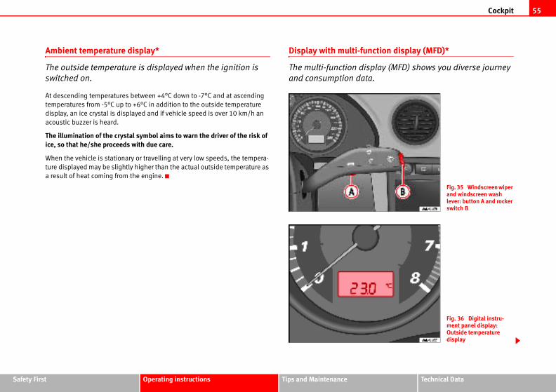
Cockpit 55
Safety Fir Technical Data
tion display (MFD)*
lay (MFD) shows you diverse journey
Fig. 35 Windscreen wiper and windscreen wash lever: button A and rocker switch B
Fig. 36 Digital instru-ment panel display: Outside temperature display
st Operating instructions Tips and Maintenance
Ambient temperature display*
The outside temperature is displayed when the ignition is
switched on.
At descending temperatures between +4°C down to -7°C and at ascending
temperatures from -5°C up to +6°C in addition to the outside temperature
display, an ice crystal is displayed and if vehicle speed is over 10 km/h an
acoustic buzzer is heard.
The illumination of the crystal symbol aims to warn the driver of the risk of ice, so that he/she proceeds with due care.
When the vehicle is stationary or travelling at very low speeds, the tempera-
ture displayed may be slightly higher than the actual outside temperature as
a result of heat coming from the engine.
Display with multi-func
The multi-function disp
and consumption data.
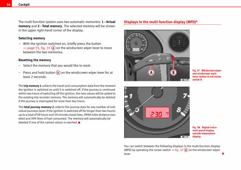
Cockpit56
nction display (MFD)*
llowing displays in the multi-function display
switch ⇒ fig. 37 on the windscreen wiper
Fig. 37 Windscreen wiper and windscreen wash lever: button A and rocker switch B
Fig. 38 Digital instru-ment panel display: outside temperature display.
AB
The multi-function system uses two automatic memories: 1 - Actual memory and 2 - Total memory. The selected memory will be shown
in the upper right-hand corner of the display.
Selecting memory
– With the ignition switched on, briefly press the button
⇒ page 55, fig. 35 on the windscreen wiper lever to move
between the two memories.
Resetting the memory
– Select the memory that you would like to reset.
– Press and hold button on the windscreen wiper lever for at
least 2 seconds.
The trip memory 1 collects the travel and consumption data from the moment
the ignition is switched on until it is switched off. If the journey is continued
within two hours of switching off the ignition, the new values will be added to
the existing trip recorder memory. The memory will automatically be deleted
if the journey is interrupted for more than two hours.
The total journey memory 2 collects the journey data for any number of indi-
vidual journeys (even if the ignition is switched off for longer than two hours)
up to a total of 99 hours and 59 minutes travel time, 9999 miles distance trav-
elled and 999 litres of fuel consumed. The memory will automatically be
deleted if one of the named values is reached.
Displays in the multi-fu
You can switch between the fo
(MFD) by operating the rocker
lever.
AA
AA
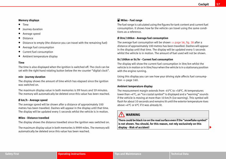
Cockpit 57
Safety Fir Technical Data
sing the figures for tank content and current fuel
ar the vehicle can travel using the same condi-
consumption
n will be shown ⇒ page 56, fig. 38 after a
0 metres has been travelled. Dashes will appear
The display will be updated every 5 seconds
n. The amount of fuel used will not be shown.
fuel consumption
rent fuel consumption in litre/km whilst the
hour when the vehicle is in a stationary position
e how your driving style affects fuel consump-
tends from -45°C to +58°C. At temperatures
al symbol” is displayed and a “warning” sounds
re than 10 km/h (ice warning). This symbol will
d remains lit until the exterior temperature rises
ready lit.
he road surface even if the “snowflake symbol” r this reason, not rely exclusively on this
st Operating instructions Tips and Maintenance
Memory displays
• Time
• Journey duration
• Average speed
• Distance
• Distance to empty (the distance you can travel with the remaining fuel)
• Average fuel consumption
• Current fuel consumption
• Ambient temperature display
Time
The time is also displayed when the ignition is switched off. The clock can be
set with the right-hand rotating button below the rev counter “digital clock”.
min - Journey duration
The display shows the amount of time which has elapsed since the ignition
was switched on.
The maximum display value in both memories is 99 hours and 59 minutes.
The memory will automatically be deleted once this value has been reached.
Ø km/h - Average speed
The average speed will be shown after a distance of approximately 100
metres has been travelled. Dashes will appear in the display until that time.
The display will be updated every 5 seconds whilst the vehicle is in motion.
Miles - Distance travelled
The display shows the distance travelled since the ignition was switched on.
The maximum display value in both memories is 9999 miles. The memory will
automatically be deleted once this value has been reached.
Miles - Fuel range
The fuel range is calculated u
consumption. It shows how f
tions as a reference.
Ø litre/100km - Average fuel
The average fuel consumptio
distance of approximately 10
in the display until that time.
whilst the vehicle is in motio
ltr/100km or ltr/hr - Current
The display will show the cur
vehicle is in motion or in litre/
with the engine running.
Using this display you can se
tion ⇒ page 160.
Ambient temperature display
The measurement margin ex
lower than +4°C, an “ice cryst
if the vehicle is moving at mo
flash for about 10 seconds an
above +4°C or 6°C if it was al
WARNING
There could be black ice on tis not shown. You should, fodisplay - Risk of accident!
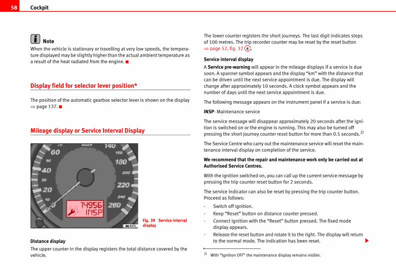
Cockpit58
e short journeys. The last digit indicates steps
er counter may be reset by the reset button
ear in the mileage displays if a service is due
ars and the display “km” with the distance that
rvice appointment is due. The display will
seconds. A clock symbol appears and the
service appointment is due.
rs on the instrument panel if a service is due:
ppear approximately 20 seconds after the igni-
ine is running. This may also be turned off
nter reset button for more than 0.5 seconds.2)
ut the maintenance service will reset the main-
mpletion of the service.
r and maintenance work only be carried out at
you can call up the current service message by
t button for 2 seconds.
be reset by pressing the trip counter button.
istance counter pressed.
“Reset” button pressed. The fixed mode
nd rotate it to the right. The display will return
indication has been reset.
nance display remains visible.
NoteWhen the vehicle is stationary or travelling at very low speeds, the tempera-
ture displayed may be slightly higher than the actual ambient temperature as
a result of the heat radiated from the engine.
Display field for selector lever position*
The position of the automatic gearbox selector lever is shown on the display
⇒ page 137.
Mileage display or Service Interval Display
Distance display
The upper counter in the display registers the total distance covered by the
vehicle.
The lower counter registers th
of 100 metres. The trip record
⇒ page 52, fig. 32 .
Service interval display
A Service pre-warning will app
soon. A spanner symbol appe
can be driven until the next se
change after approximately 10
number of days until the next
The following message appea
INSP- Maintenance service
The service message will disa
tion is switched on or the eng
pressing the short journey cou
The Service Centre who carry o
tenance interval display on co
We recommend that the repaiAuthorised Service Centres.
With the ignition switched on,
pressing the trip counter rese
The service indicator can also
Proceed as follows:
- Switch off ignition.
- Keep “Reset” button on d
- Connect ignition with the
display appears.
- Release the reset button a
to the normal mode. The
Fig. 39 Service interval display
2) With “Ignition OFF” the mainte
A6
Cockpit 59
Safety Fir Technical Data
st Operating instructions Tips and MaintenanceCautionWe recommend that the resetting of the service interval indicator be carried
out in an Authorised Service Centre to avoid possible faults in the vehicle.
Note• The indication can only be reset when a pre-warning or warning is indi-
cated.
• Do not reset the display between two service intervals, otherwise the
display will be incorrect.
• The values are stored even when the battery is disconnected.
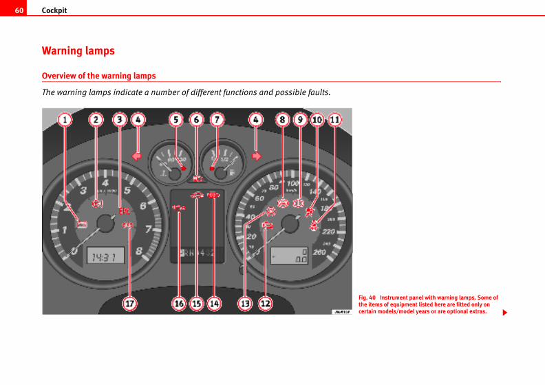
Cockpit60
. 40 Instrument panel with warning lamps. Some of items of equipment listed here are fitted only on tain models/model years or are optional extras.
Warning lamps
Overview of the warning lamps
The warning lamps indicate a number of different functions and possible faults.
Figthecer
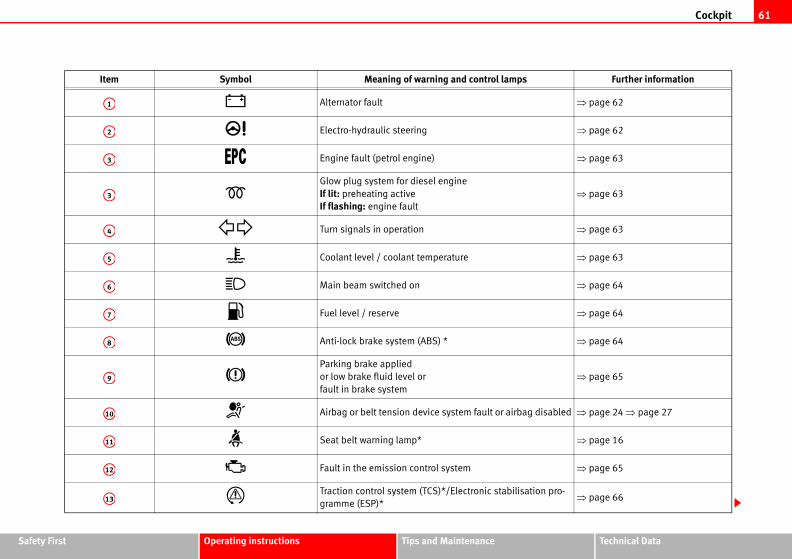
Cockpit 61
Safety Fir Technical Data
Further information
⇒ page 62
⇒ page 62
⇒ page 63
⇒ page 63
⇒ page 63
⇒ page 63
⇒ page 64
⇒ page 64
⇒ page 64
⇒ page 65
disabled ⇒ page 24 ⇒ page 27
⇒ page 16
⇒ page 65
ion pro-⇒ page 66
st Operating instructions Tips and Maintenance
Item Symbol Meaning of warning and control lamps
Alternator fault
Electro-hydraulic steering
Engine fault (petrol engine)
Glow plug system for diesel engine
If lit: preheating active
If flashing: engine fault
Turn signals in operation
Coolant level / coolant temperature
Main beam switched on
Fuel level / reserve
Anti-lock brake system (ABS) *
Parking brake applied
or low brake fluid level or
fault in brake system
Airbag or belt tension device system fault or airbag
Seat belt warning lamp*
Fault in the emission control system
Traction control system (TCS)*/Electronic stabilisat
gramme (ESP)*
A1
A2
A3
A3
A4
A5
A6
A7
A8
A9
A10
A11
A12
A13
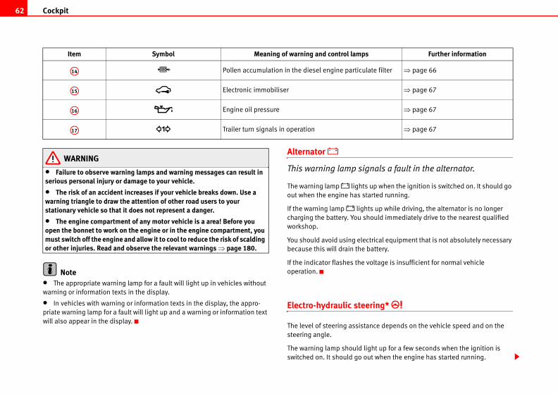
Cockpit62
als a fault in the alternator.
when the ignition is switched on. It should go
ed running.
up while driving, the alternator is no longer
ld immediately drive to the nearest qualified
cal equipment that is not absolutely necessary
ttery.
tage is insufficient for normal vehicle
ng*
e depends on the vehicle speed and on the
t up for a few seconds when the ignition is
when the engine has started running.
filter ⇒ page 66
⇒ page 67
⇒ page 67
⇒ page 67
Further information
WARNING
• Failure to observe warning lamps and warning messages can result in serious personal injury or damage to your vehicle.
• The risk of an accident increases if your vehicle breaks down. Use a warning triangle to draw the attention of other road users to your stationary vehicle so that it does not represent a danger.
• The engine compartment of any motor vehicle is a area! Before you open the bonnet to work on the engine or in the engine compartment, you must switch off the engine and allow it to cool to reduce the risk of scalding or other injuries. Read and observe the relevant warnings ⇒ page 180.
Note• The appropriate warning lamp for a fault will light up in vehicles without
warning or information texts in the display.
• In vehicles with warning or information texts in the display, the appro-
priate warning lamp for a fault will light up and a warning or information text
will also appear in the display.
Alternator
This warning lamp sign
The warning lamp lights up
out when the engine has start
If the warning lamp lights
charging the battery. You shou
workshop.
You should avoid using electri
because this will drain the ba
If the indicator flashes the vol
operation.
Electro-hydraulic steeri
The level of steering assistanc
steering angle.
The warning lamp should ligh
switched on. It should go out
Pollen accumulation in the diesel engine particulate
Electronic immobiliser
Engine oil pressure
Trailer turn signals in operation
Item Symbol Meaning of warning and control lamps
A14
A15
A16
A17
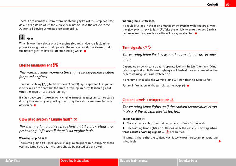
Cockpit 63
Safety Fir Technical Data
ine management system while you are driving,
. Take the vehicle to an Authorised Service
nd have the engine checked.
es when the turn signals are in oper-
nal is operated, either the left or right indi-
ing lamps will flash at the same time when the
itched on.
rning lamp will start flashing twice as fast.
rn signals ⇒ page 93.
rature
s up if the coolant temperature is too
vel is too low.
not go out again after a few seconds.
p or flashes while the vehicle is moving, while
ls ⇒ are emitted.
olant level is too low or the coolant temperature
st Operating instructions Tips and Maintenance
There is a fault in the electro-hydraulic steering system if the lamp does not
go out or lights up whilst the vehicle is in motion. Take the vehicle to the
Authorised Service Centre as soon as possible.
NoteWhen towing the vehicle with the engine stopped or due to a fault in the
power steering, this will not operate. The vehicle can still be steered, but it
will require greater force to turn the steering wheel.
Engine management
This warning lamp monitors the engine management system
for petrol engines.
The warning lamp (Electronic Power Control) lights up when the ignition
is switched on to show that the lamp is working properly. It should go out
when the engine has started running.
If a fault develops in the electronic engine management system while you are
driving, this warning lamp will light up. Stop the vehicle and seek technical
assistance.
Glow plug system / Engine fault*
The warning lamp lights up to show that the glow plugs are
preheating. It flashes if there is an engine fault.
Warning lamp is lit
The warning lamp lights up while the glow plugs are preheating. When the
warning lamp goes off, the engine should be started straight away.
Warning lamp flashes
If a fault develops in the eng
the glow plug lamp will flash
Centre as soon as possible a
Turn signals
The warning lamp flash
ation.
Depending on which turn sig
cator lamp flashes. Both warn
hazard warning lights are sw
If one turn signal fails, the wa
Further information on the tu
Coolant Level* / tempe
The warning lamp light
high or if the coolant le
There is a fault if:
• The warning symbol does
• The warning lamp lights u
three acoustic warning signa
This means that either the co
is too high.
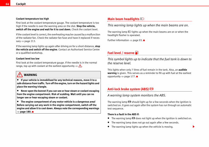
Cockpit64
s up when the main beams are on.
p when the main beams are on or when the
3.
indicate that the fuel tank is down to
f fuel remain in the tank. Also, an audible as a reminder to fill up with fuel at the earliest
(ABS)
monitors the ABS.
ight up for a few seconds when the ignition is
after the system has run through an automatic
not light up when the ignition is switched on.
t go out again after a few seconds.
p when the vehicle is moving.
Coolant temperature too high
First look at the coolant temperature gauge. The coolant temperature is too
high if the needle is over the warning area on the dial. Stop the vehicle, switch off the engine and wait for it to cool down. Check the coolant level.
If the coolant level is correct, the overheating may be caused by a malfunction
of the radiator fan. Check the radiator fan fuse and have it replaced if neces-
sary ⇒ page 213.
If the warning lamp lights up again after driving on for a short distance, stop the vehicle and switch off the engine. Contact an Authorised Service Centre
or a qualified workshop.
Coolant level too low
First look at the coolant temperature gauge. If the needle is in the normal
range, top up with coolant at the earliest opportunity ⇒ .
WARNING
• If your vehicle is immobilised for any technical reasons, move it to a safe distance from traffic. Turn off the engine, turn on the hazard lights and place the warning triangle.
• Never open the bonnet if you can see or hear steam or coolant escaping from the engine compartment. Risk of scalding. Wait until you can no longer see or hear escaping steam or coolant.
• The engine compartment of any motor vehicle is a dangerous area! Before carrying out any work in the engine compartment, switch off the engine and allow it to cool down. Always note the corresponding warnings ⇒ page 180.
Main beam headlights
This warning lamp light
The warning lamp lights u
headlight flasher is operated.
Further information ⇒ page 9
Fuel level / reserve
This symbol lights up to
the reserve level.
This lights when only 7 litres o
warning is given. This serves
opportunity ⇒ page 177.
Anti-lock brake system
A warning lamp system
The warning lamp should l
switched on. It goes out again
test sequence.
There is a fault in the ABS if:
• The warning lamp does
• The warning lamp does no
• The warning lamp lights u
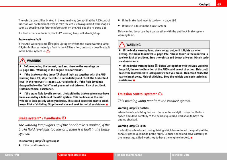
Cockpit 65
Safety Fir Technical Data
oo low ⇒ page 192
ake system
p together with the anti-lock brake system
p does not go out, or if it lights up when l ⇒ page 192, “Brake fluid” in the reservoir is
p the vehicle and do not drive on. Obtain tech-
p lights up together with the ABS warning n of the ABS could be out of action. This could k quickly when you brake. This could cause the kidding. Stop the vehicle and seek technical
m*
itors the exhaust system.
an damage the catalytic converter. Reduce
he nearest qualified workshop to have the
g driving which has reduced the quality of the
be fault). Reduce speed and drive carefully to
op to have the engine checked.
st Operating instructions Tips and Maintenance
The vehicle can still be braked in the normal way (except that the ABS control
function will not function). Please take the vehicle to a qualified workshop as
soon as possible. For further information on the ABS see the ⇒ page 148.
If a fault occurs in the ABS, the ESP* warning lamp will also light up.
Brake system fault
If the ABS warning lamp lights up together with the brake warning lamp
, this indicates not only a fault in the ABS function, but also a possible fault
in the brake system ⇒ .
WARNING
• Before opening the bonnet, read and observe the warnings on ⇒ page 180, “Working in the engine compartment”.
• If the brake warning lamp should light up together with the ABS warning lamp , stop the vehicle immediately and check the brake fluid level in the reservoir ⇒ page 192, “Brake fluid”. If the fluid level has dropped below the “MIN” mark you must not drive on. Risk of accident. Obtain technical assistance.
• If the brake fluid level is correct, the fault in the brake system may have been caused by a failure of the ABS system. This could cause the rear wheels to lock quickly when you brake. This could cause the rear to break away. Risk of skidding. Stop the vehicle and seek technical assistance.
Brake system* / handbrake
The warning lamp lights up if the handbrake is applied, if the
brake fluid level falls too low or if there is a fault in the brake
system.
This warning lamp lights up if
• If the handbrake is on
• If the brake fluid level is t
• If there is a fault in the br
This warning lamp can light u
warning lamp.
WARNING
• If the brake warning lamdriving, the brake fluid levetoo low. Risk of accident. Stonical assistance.
• If the brake warning lamlamp , the control functiocause the rear wheels to locrear to break away. Risk of sassistance.
Emission control syste
This warning lamp mon
Warning lamp flashes:
When there is misfiring that c
speed and drive carefully to t
engine checked.
Warning lamp is lit:
If a fault has developed durin
exhaust gas (e.g. lambda pro
the nearest qualified worksh
Cockpit66
ctivated by switching the ignition off and then
goes out, this means the system is fully
e diesel engine particulate filter *
ay help the filter clear itself by driving in the
utes in 4th or 5th gear (automatic gearbox: S
m/h, with the engine running at approximately
len build up in the filter is burned. When
icator turns off.
ivated, bring the vehicle to a specialised work-
the road weather conditions, the terrain and ions should never lead to illegal maneouvers
late filter may reach extremely high tempera- contact with flammable materials under-
comply could result in fire.
el engine particulate filter must not be refueled
hat the fuel system may be damaged.
Traction control system (TCS)*
The traction control system prevents the driven wheels from
spinning when the vehicle is accelerating
The warning lamp lights up when the ignition is switched on and should turn
out after about 2 seconds.
When the TCS is operating while driving, the warning lamp flashes. If the
system is deactivated or if there is any fault in the same, the warning lamp will
remain lit.
It will also come on if a fault should occur in the ABS because the TCS oper-
ates in conjunction with the ABS. For further information see ⇒ page 147,
“Brakes”.
Electronic stabilisation programme (ESP)*
This warning lamp monitors the electronic stabilisation
programme.
This programme includes the ABS, EDL and TCS.
The warning lamp has the following functions:
• It will light for about 2 seconds when the ignition is switched on while a
test of the function is carried out.
• It flashes when the ESP is activated when driving.
• It will light up continuously if there is a malfunction in the ESP.
• It will light up continuously if the ESP is switched off.
• It will also come on if a fault should occur in the ABS because the ESP
operates in conjunction with the ABS.
If the ESP warning lamp lights up and stays on after the engine is started,
this may mean that the control system has temporarily switched off the ESP.
In this case the ESP can be rea
on again. If the warning lamp
functional.
Soot accumulation in th
If the indicator lights you m
appropriate manner.
To do this, drive about 15 min
gear range) at a speed of 60 k
2000 rpm. In this way, the pol
cleaning is successful, the ind
If the indicator is not deact
shop to repair the fault.
WARNING
• Always drive according totraffic. Driving recommendatin surrounding traffic.
• The diesel engine particutures; it should not enter intoneath the vehicle. Failure to
CautionVehicles equipped with a dies
using biodiesel (RME), given t
Cockpit 67
Safety Fir Technical Data
flashes when the turn signals are
a caravan or trailer.
when the turn signals are operated, provided a
d connected to the vehicle.
sh if one of the turn signals on the trailer fails.
EDL)*
the ABS in vehicles equipped with an
Program (ESP)*
dicated by the ABS warning lamp . Please
workshop as soon as possible. For further infor-
50, “Electronic differential lock (EDL)*”
st Operating instructions Tips and Maintenance
Electronic immobiliser
Inside the key there is a chip that deactivates the electronic immobiliser auto-
matically when the key is inserted into the ignition. The immobiliser will be
activated again automatically as soon as you pull the key out of the ignition
lock.
The engine can, however, be started if the appropriate coded SEAT genuine
key is used.
NoteThe vehicle cannot be operated properly if you do not have a genuine SEAT
key.
Engine oil pressure
This warning lamp indicates that the engine oil pressure is
too low.
If this warning symbol starts to flash, and is accompanied by three audible warnings, switch off the engine and check the oil level. If the oil level is too
low, add more engine oil ⇒ page 183.
If the symbol flashes although the oil level is correct, do not drive on. The
engine must not even run at idle speed. Obtain technical assistance.
Trailer turn signals
This warning lamp also
operated while towing
The warning lamp flashes
trailer is correctly attached an
The warning lamp will not fla
Differential lock fault (
EDL operates along with
Electronic Stabilisation
A malfunction in the EDL is in
take the vehicle to a qualified
mation on the EDL ⇒ page 1
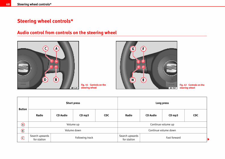
Steering wheel controls*68
Fig. 42 Controls on the steering wheel
Long press
udio CD mp3 CDC
ontinue volume up
ntinue volume down
Fast forward
Steering wheel controls*
Audio control from controls on the steering wheel
Fig. 41 Controls on the steering wheel
Button
Short press
Radio CD Audio CD mp3 CDC Radio CD A
Volume up C
Volume down Co
Search upwards
for stationFollowing track
Search upwards
for station
AB
AC
AA
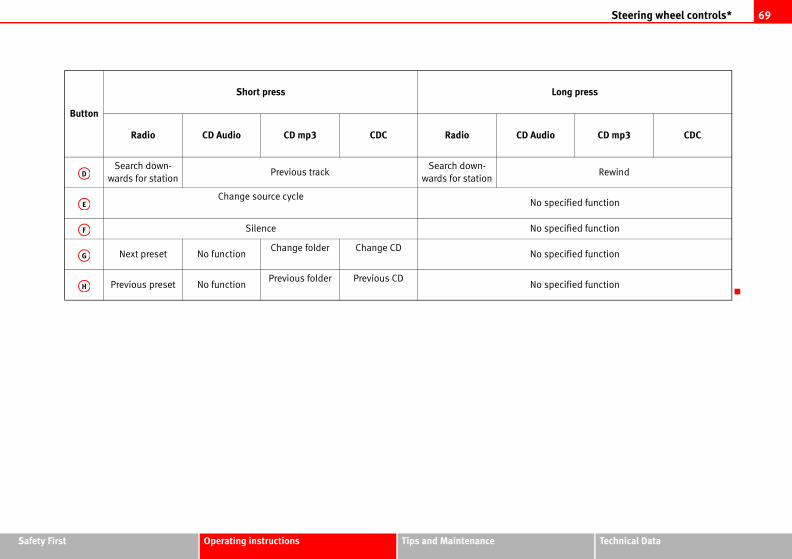
Steering wheel controls* 69
Safety Fir Technical Data
Long press
udio CD mp3 CDC
Rewind
o specified function
o specified function
o specified function
o specified function
st Operating instructions Tips and Maintenance
Button
Short press
Radio CD Audio CD mp3 CDC Radio CD A
Search down-
wards for stationPrevious track
Search down-
wards for station
Change source cycle N
Silence N
Next preset No functionChange folder Change CD
N
Previous preset No functionPrevious folder Previous CD
N
AD
AE
AF
AG
AH
Unlocking and locking70
without taking care or observing all the r other people especially children.
ever leave children unaccompanied inside, as ssistance if required.
d, any intrusion is impeded, for example while
m enables you to lock and unlock all
te from one point.
ed using any of the following options:
the driver's door cylinder and rotating manu-
, (electronic control) in the passenger compart-
e control, using the buttons on the key
e to improve the vehicle security:
m*
Unlocking and locking
Doors
Locking and unlocking the vehicle
From the outside of the vehicle, the driver's door may be
locked or unlocked using the key.
When opened, the latch will rise up (for vehicles without central locking)
For vehicles equipped with electric windows and central locking, if the key is
maintained in the opening position all of the electric side windows will open.
When locking the latch will descend (for vehicles without central locking)
In some vehicle models equipped with electric windows and central locking,
if the key is maintained in the locking position on the driver side, any side
windows left open, as well as the electric sunroof, will close.
For vehicles without central locking, the passenger door and the rear doors
may be locked from the outside without using a key. Just press the button
down and close the door.
The latch on the driver’s door may not be pushed down while the door is open
(only in vehicles without central locking). This avoids accidentally leaving the
keys in the ignition.
From inside all the doors may be locked by pushing the security buttons down
(in vehicles without central locking).
WARNING
• Exercise extreme caution when closing the windows and the sunroof from the outside of the vehicle.
• Closing from the outside vehicle may cause bruising fo
• When locking a vehicle, nit will be difficult to provide a
• When the doors are lockestopped at a red light.
Central locking*
Description
The central locking syste
the doors and the tailga
Central locking can be activat
• the key, by inserting it into
ally,
• the central locking buttonment ⇒ page 73,
• the radio frequency remot⇒ page 78.
Various functions are availabl
- Locking system “Safe”
- Selective unlocking syste
WARNING (continued)
Unlocking and locking 71
Safety Fir Technical Data
the remote control, press the lock button on the
eactivated, the alarm volumetric sensor is also
activated, the doors are locked using the simple
t they may be opened from the interior but not
eactivation of the “Safe” system may be
ample, if we press the button because we
it locks as a result, however, we are not sure that
utton once more within 2 seconds, we will have
m).
pening, see “Selective unlocking system*”.
a light indicator visible from the outside of the
fe” system status.
ystem is activated, by the flashing of the light
ash on all vehicles, whether they are fitted with
vehicle is unlocked.
t alarm: Indicator flashes continuously.
rm: The indicator remains off.
The indicator remains off.
st Operating instructions Tips and Maintenance
- Auto-locking to prevent involuntary unlocking
- Automatic speed dependent locking and unlocking system*
- Emergency unlocking system
NoteFor anti-theft security, only the driver's door is fitted with a lock cylinder.
Safety system “Safe”
This is an anti-theft device consisting of a double lock for the
door locks and a deactivation function for the boot in order to
make forced entry more difficult.
Activation
The “safe” system is activated when the vehicle is locked using the key or the
remote control.
To activate this system with the key, rotate the key once in the door lock
cylinder in the locking direction.
To activate the system using the remote control, press the lock button on the
remote once.
When this system is activated, it is not possible to open the doors normally,
from the outside or the inside. The boot/tailgate may not be opened. The
central locking button does not work.
Voluntary deactivation
The “Safe” system can be deactivated voluntarily by the user.
This is done by locking two times in quick succession (in under 2 seconds).
This double locking can be executed using the key or the remote control.
Using the key, rotate the lock cylinder twice in the locking direction.
To activate the system using
remote twice.
When the “Safe” system is d
deactivated.
When the “Safe” system is de
locking system, meaning tha
from the exterior.
Involuntary deactivation
The methods described for d
executed involuntarily (for ex
want to lock the vehicle, and
it is locked and we press the b
deactivated the “Safe” syste
Deactivation when opening
To deactivate the system on o
“Safe” status
On the driver's door, there is
vehicle that indicates the “Sa
We can see that the “Safe” s
indicator. The indicator will fl
an alarm or not, and until the
Remember:
Safe activated with or withou
Safe deactivated without ala
Safe deactivated with alarm:
Unlocking and locking72
3.
luntary unlocking
em and will avoid situations where
intentionally
utomatically, if it is unlocked and neither the
pened within 30 seconds. This function
aining unlocked if the unlocking button is
dent locking and unlocking system*
o prevent access to the vehicle from
hicle is in transit (for example, when
).
omatically locked when vehicle speed exceeds
ne of the doors is opened, when the vehicle
speed of 15 km/h the unlocked door(s) will be
y unlocks when the key is removed from the
WARNING
No one should remain in the vehicle if the “Safe” deadlock mechanism has been activated. It is not possible to open the doors from the inside or the outside and this would make any outside intervention difficult in case of emergency. Danger of death. People could become trapped inside in an emergency.
Selective unlocking system*
This system allows for unlocking only the driver's door, or all
the vehicle.
Driver's door unlock button
This is done by a simple unlocking (once). This can be done with the key or
the remote control.
With the key, rotate the key once in the lock cylinder in the unlock direction.
The driver's door will be released from the “Safe” system and unlocked and
may be opened, the indicator light will also be switched off. For vehicles fitted
with an alarm, this system is deactivated.
Using the remote control, press the unlock button on the remote once. The
“Safe” system is deactivated for all the vehicle, only the driver's door is
unlocked for opening, the alarm is turned off as is the light indicator.
Unlocking all doors and the boot
So that all the doors and the boot can be opened, the unlock button on
the remote must be pressed twice.
The button must be pressed twice in under 2 seconds and this will deactivate
the “Safe” system for all the vehicle, all doors will be unlocked and the boot
will be activated. The indicator will be turned off as will be the alarm for those
vehicles fitted with one.
Unlocking the boot
See ⇒ page 78 and ⇒ page 8
Locking system for invo
This is an anti-theft syst
the vehicle is opened un
The vehicle will be re-locked a
boot or any of the doors are o
prevents the vehicle from rem
pressed by mistake.
Automatic speed depen
This is a safety system t
the exterior when the ve
stopped at a traffic light
Locking
The doors and the boot are aut
15 km/h.
If the vehicle is stopped and o
moves off again and exceeds a
locked once more.
Unlocking
The driver's door automaticall
ignition.
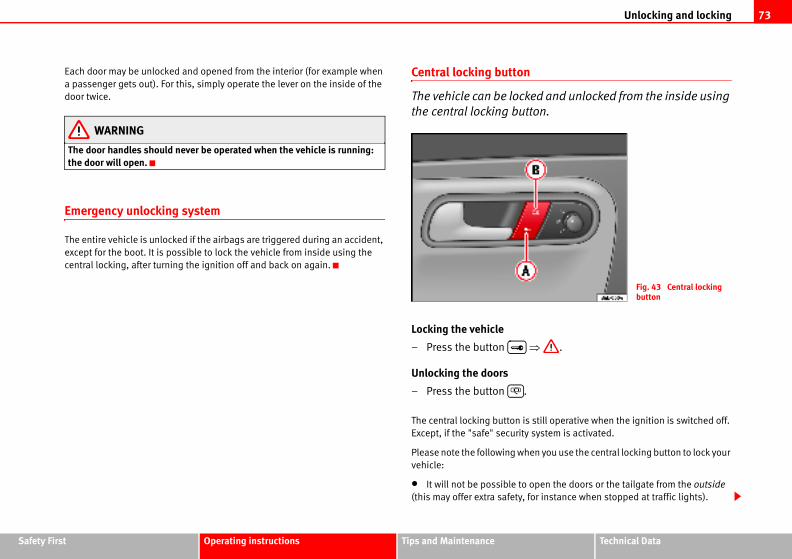
Unlocking and locking 73
Safety Fir Technical Data
d and unlocked from the inside using
on.
.
still operative when the ignition is switched off.
system is activated.
n you use the central locking button to lock your
pen the doors or the tailgate from the outside
r instance when stopped at traffic lights).
Fig. 43 Central locking button
st Operating instructions Tips and Maintenance
Each door may be unlocked and opened from the interior (for example when
a passenger gets out). For this, simply operate the lever on the inside of the
door twice.
WARNING
The door handles should never be operated when the vehicle is running: the door will open.
Emergency unlocking system
The entire vehicle is unlocked if the airbags are triggered during an accident,
except for the boot. It is possible to lock the vehicle from inside using the
central locking, after turning the ignition off and back on again.
Central locking button
The vehicle can be locke
the central locking butt
Locking the vehicle
– Press the button ⇒
Unlocking the doors
– Press the button .
The central locking button is
Except, if the "safe" security
Please note the following whe
vehicle:
• It will not be possible to o
(this may offer extra safety, fo
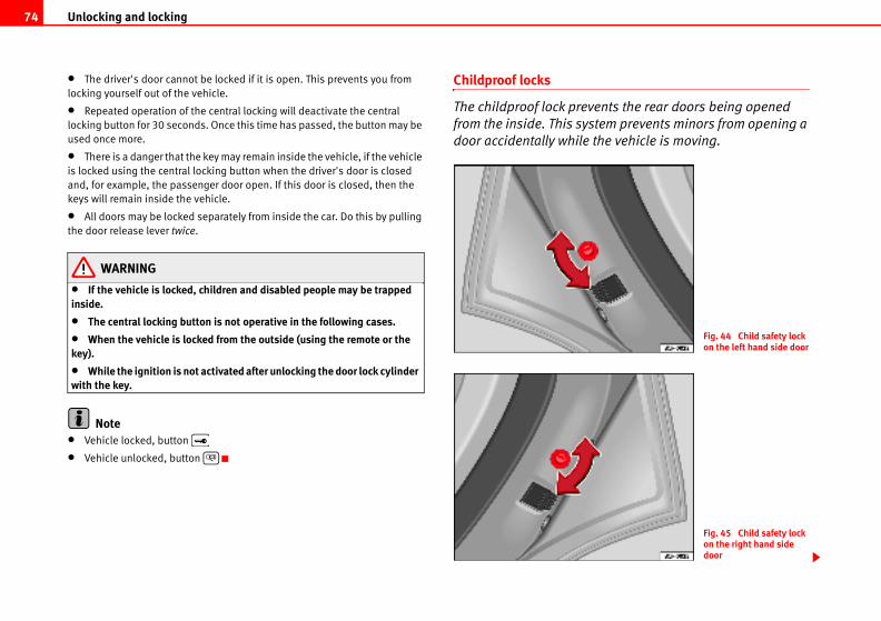
Unlocking and locking74
ents the rear doors being opened
tem prevents minors from opening a
the vehicle is moving.
Fig. 44 Child safety lock on the left hand side door
Fig. 45 Child safety lock on the right hand side door
• The driver's door cannot be locked if it is open. This prevents you from
locking yourself out of the vehicle.
• Repeated operation of the central locking will deactivate the central
locking button for 30 seconds. Once this time has passed, the button may be
used once more.
• There is a danger that the key may remain inside the vehicle, if the vehicle
is locked using the central locking button when the driver's door is closed
and, for example, the passenger door open. If this door is closed, then the
keys will remain inside the vehicle.
• All doors may be locked separately from inside the car. Do this by pulling
the door release lever twice.
WARNING
• If the vehicle is locked, children and disabled people may be trapped inside.
• The central locking button is not operative in the following cases.
• When the vehicle is locked from the outside (using the remote or the key).
• While the ignition is not activated after unlocking the door lock cylinder with the key.
Note• Vehicle locked, button
• Vehicle unlocked, button
Childproof locks
The childproof lock prev
from the inside. This sys
door accidentally while
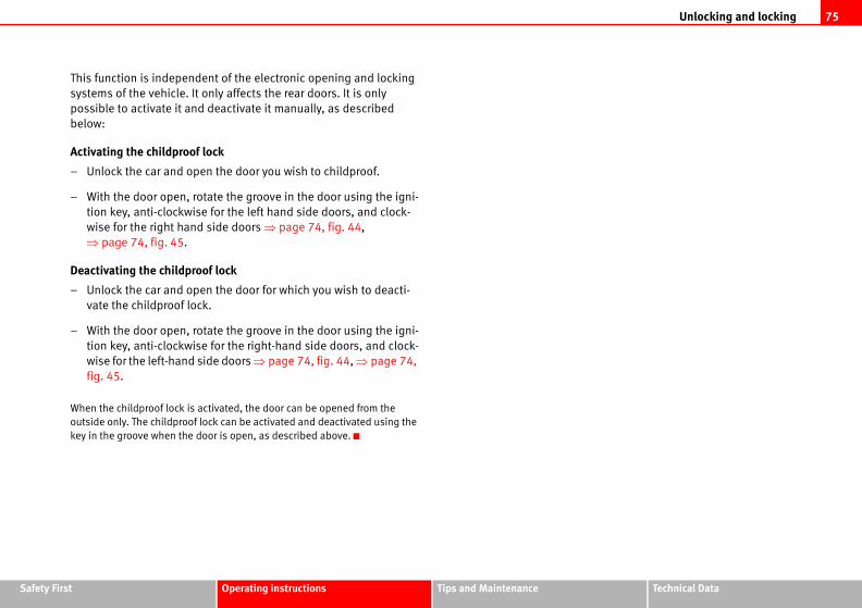
Unlocking and locking 75
Safety Fir Technical Data
st Operating instructions Tips and MaintenanceThis function is independent of the electronic opening and locking
systems of the vehicle. It only affects the rear doors. It is only
possible to activate it and deactivate it manually, as described
below:
Activating the childproof lock
– Unlock the car and open the door you wish to childproof.
– With the door open, rotate the groove in the door using the igni-
tion key, anti-clockwise for the left hand side doors, and clock-
wise for the right hand side doors ⇒ page 74, fig. 44,
⇒ page 74, fig. 45.
Deactivating the childproof lock
– Unlock the car and open the door for which you wish to deacti-
vate the childproof lock.
– With the door open, rotate the groove in the door using the igni-
tion key, anti-clockwise for the right-hand side doors, and clock-
wise for the left-hand side doors ⇒ page 74, fig. 44, ⇒ page 74,
fig. 45.
When the childproof lock is activated, the door can be opened from the
outside only. The childproof lock can be activated and deactivated using the
key in the groove when the door is open, as described above.
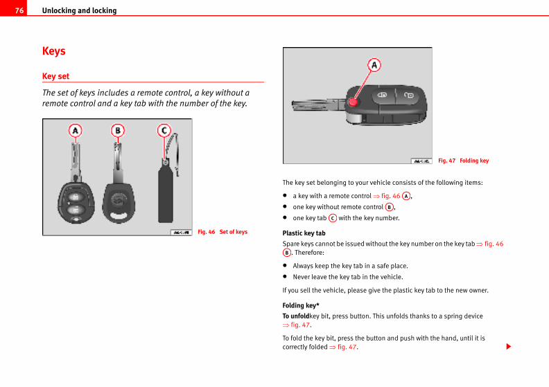
Unlocking and locking76
vehicle consists of the following items:
l ⇒ fig. 46 ,
ntrol ,
y number.
ithout the key number on the key tab ⇒ fig. 46
a safe place.
the vehicle.
give the plastic key tab to the new owner.
. This unfolds thanks to a spring device
utton and push with the hand, until it is
Fig. 47 Folding key
AA
AB
Keys
Key set
The set of keys includes a remote control, a key without a
remote control and a key tab with the number of the key.
The key set belonging to your
• a key with a remote contro
• one key without remote co
• one key tab with the ke
Plastic key tab
Spare keys cannot be issued w
. Therefore:
• Always keep the key tab in
• Never leave the key tab in
If you sell the vehicle, please
Folding key*
To unfoldkey bit, press button
⇒ fig. 47.
To fold the key bit, press the b
correctly folded ⇒ fig. 47.
Fig. 46 Set of keys
AC
AB
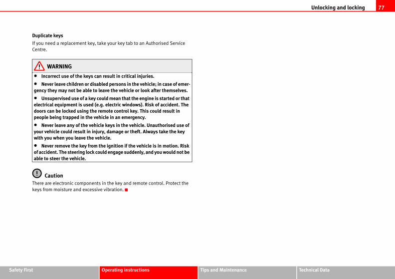
Unlocking and locking 77
Safety Fir Technical Data
st Operating instructions Tips and MaintenanceDuplicate keys
If you need a replacement key, take your key tab to an Authorised Service
Centre.
WARNING
• Incorrect use of the keys can result in critical injuries.
• Never leave children or disabled persons in the vehicle; in case of emer-gency they may not be able to leave the vehicle or look after themselves.
• Unsupervised use of a key could mean that the engine is started or that electrical equipment is used (e.g. electric windows). Risk of accident. The doors can be locked using the remote control key. This could result in people being trapped in the vehicle in an emergency.
• Never leave any of the vehicle keys in the vehicle. Unauthorised use of your vehicle could result in injury, damage or theft. Always take the key with you when you leave the vehicle.
• Never remove the key from the ignition if the vehicle is in motion. Risk of accident. The steering lock could engage suddenly, and you would not be able to steer the vehicle.
CautionThere are electronic components in the key and remote control. Protect the
keys from moisture and excessive vibration.
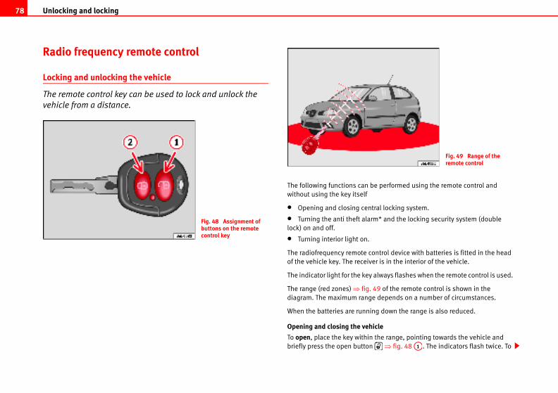
Unlocking and locking78
e performed using the remote control and
al locking system.
* and the locking security system (double
ntrol device with batteries is fitted in the head
r is in the interior of the vehicle.
lways flashes when the remote control is used.
9 of the remote control is shown in the
depends on a number of circumstances.
g down the range is also reduced.
cle
the range, pointing towards the vehicle and
⇒ fig. 48 . The indicators flash twice. To
Fig. 49 Range of the remote control
A1
Radio frequency remote control
Locking and unlocking the vehicle
The remote control key can be used to lock and unlock the
vehicle from a distance.
The following functions can b
without using the key itself
• Opening and closing centr
• Turning the anti theft alarm
lock) on and off.
• Turning interior light on.
The radiofrequency remote co
of the vehicle key. The receive
The indicator light for the key a
The range (red zones) ⇒ fig. 4
diagram. The maximum range
When the batteries are runnin
Opening and closing the vehi
To open, place the key within
briefly press the open button
Fig. 48 Assignment of buttons on the remote control key
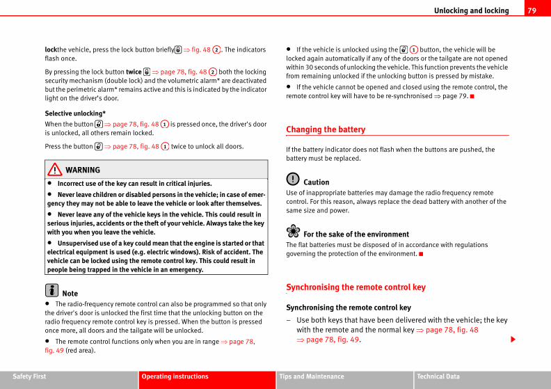
Unlocking and locking 79
Safety Fir Technical Data
using the button, the vehicle will be
any of the doors or the tailgate are not opened
g the vehicle. This function prevents the vehicle
e unlocking button is pressed by mistake.
pened and closed using the remote control, the
to be re-synchronised ⇒ page 79.
ot flash when the buttons are pushed, the
s may damage the radio frequency remote
ys replace the dead battery with another of the
nvironmentposed of in accordance with regulations
he environment.
ote control key
control key
e been delivered with the vehicle; the key
e normal key ⇒ page 78, fig. 48
A1
st Operating instructions Tips and Maintenance
lockthe vehicle, press the lock button briefly ⇒ fig. 48 . The indicators
flash once.
By pressing the lock button twice ⇒ page 78, fig. 48 both the locking
security mechanism (double lock) and the volumetric alarm* are deactivated
but the perimetric alarm* remains active and this is indicated by the indicator
light on the driver’s door.
Selective unlocking*
When the button ⇒ page 78, fig. 48 is pressed once, the driver's door
is unlocked, all others remain locked.
Press the button ⇒ page 78, fig. 48 twice to unlock all doors.
WARNING
• Incorrect use of the key can result in critical injuries.
• Never leave children or disabled persons in the vehicle; in case of emer-gency they may not be able to leave the vehicle or look after themselves.
• Never leave any of the vehicle keys in the vehicle. This could result in serious injuries, accidents or the theft of your vehicle. Always take the key with you when you leave the vehicle.
• Unsupervised use of a key could mean that the engine is started or that electrical equipment is used (e.g. electric windows). Risk of accident. The vehicle can be locked using the remote control key. This could result in people being trapped in the vehicle in an emergency.
Note• The radio-frequency remote control can also be programmed so that only
the driver's door is unlocked the first time that the unlocking button on the
radio frequency remote control key is pressed. When the button is pressed
once more, all doors and the tailgate will be unlocked.
• The remote control functions only when you are in range ⇒ page 78,
fig. 49 (red area).
• If the vehicle is unlocked
locked again automatically if
within 30 seconds of unlockin
from remaining unlocked if th
• If the vehicle cannot be o
remote control key will have
Changing the battery
If the battery indicator does n
battery must be replaced.
CautionUse of inappropriate batterie
control. For this reason, alwa
same size and power.
For the sake of the eThe flat batteries must be dis
governing the protection of t
Synchronising the rem
Synchronising the remote
– Use both keys that hav
with the remote and th
⇒ page 78, fig. 49.
A2
A2
A1
A1
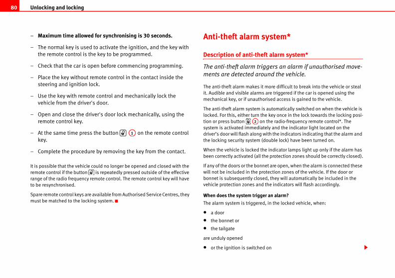
Unlocking and locking80
ystem*
t alarm system*
gers an alarm if unauthorised move-
nd the vehicle.
ore difficult to break into the vehicle or steal
are triggered if the car is opened using the
rised access is gained to the vehicle.
automatically switched on when the vehicle is
e key once in the lock towards the locking posi-
the radio-frequency remote control*. The
ly and the indicator light located on the
ith the indicators indicating that the alarm and
ouble lock) have been turned on.
indicator lamps light up only if the alarm has
e protection zones should be correctly closed).
et are open, when the alarm is connected these
tection zones of the vehicle. If the door or
d, they will automatically be included in the
the indicators will flash accordingly.
r an alarm?
, in the locked vehicle, when:
on
– Maximum time allowed for synchronising is 30 seconds.
– The normal key is used to activate the ignition, and the key with
the remote control is the key to be programmed.
– Check that the car is open before commencing programming.
– Place the key without remote control in the contact inside the
steering and ignition lock.
– Use the key with remote control and mechanically lock the
vehicle from the driver's door.
– Open and close the driver's door lock mechanically, using the
remote control key.
– At the same time press the button on the remote control
key.
– Complete the procedure by removing the key from the contact.
It is possible that the vehicle could no longer be opened and closed with the
remote control if the button is repeatedly pressed outside of the effective
range of the radio frequency remote control. The remote control key will have
to be resynchronised.
Spare remote control keys are available from Authorised Service Centres, they
must be matched to the locking system.
Anti-theft alarm s
Description of anti-thef
The anti-theft alarm trig
ments are detected arou
The anti-theft alarm makes it m
it. Audible and visible alarms
mechanical key, or if unautho
The anti-theft alarm system is
locked. For this, either turn th
tion or press button on
system is activated immediate
driver’s door will flash along w
the locking security system (d
When the vehicle is locked the
been correctly activated (all th
If any of the doors or the bonn
will not be included in the pro
bonnet is subsequently close
vehicle protection zones and
When does the system trigge
The alarm system is triggered
• a door
• the bonnet or
• the tailgate
are unduly opened
• or the ignition is switched
A1
A2
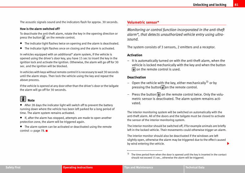
Unlocking and locking 81
Safety Fir Technical Data
nction incorporated in the anti-theft
authorized vehicle entry using ultra-
ensors, 2 emitters and a receptor.
ed on with the anti-theft alarm, when the
anically with the key and when the button
rol is used.
the key, either mechanically3) or by
on the remote control.
the remote control twice. Only the volu-
ivated. The alarm system remains acti-
m will be switched on automatically with the
ors and the tailgate must be closed to activate
nitoring system.
e switched off, if for example animals are briefly
ir movements could otherwise trigger an alarm.
lso be deactivated if the windows are left
larm may be triggered due to the effect caused
e door is opened until the key is inserted in the contact
herwise the alarm will be triggered.
st Operating instructions Tips and Maintenance
The acoustic signals sound and the indicators flash for approx. 30 seconds.
How is the alarm switched off?
To deactivate the anti-theft alarm, rotate the key in the opening direction or
press the button on the remote control.
• The indicator light flashes twice on opening and the alarm is deactivated.
• The indicator light flashes once on closing and the alarm is activated.
In vehicles equipped with an additional* alarm system, if the vehicle is
opened using the driver's door key, you have 15 sec to insert the key in the
ignition lock and activate the ignition. Otherwise, the alarm will go off for 30
sec. and the ignition will be blocked.
In vehicles with keys without remote control it is necessary to wait 30 seconds
until the alarm stops. Then lock the vehicle using the key and repeat the
above process.
If the vehicle is opened at any door other than the driver's door or the tailgate
the alarm will go off for 30 seconds.
Note• After 28 days the indicator light will switch off to prevent the battery
running down where the vehicle has been left parked for a long period of
time. The alarm system remains activated.
• If, after the alarm has stopped, attempts are made to open another
protection zone, the alarm will be triggered again.
• The alarm system can be activated or deactivated using the remote
control ⇒ page 78.
Volumetric sensor*
Monitoring or control fu
alarm*, that detects un
sound.
The system consists of 3 s
Activation
– It is automatically turn
vehicle is locked mech
on the remote cont
Deactivation
– Open the vehicle with
pressing the button
– Press the button on
metric sensor is deact
vated.
The interior monitoring syste
anti-theft alarm. All of the do
the sensor of the interior mo
The interior monitor should b
left in the locked vehicle. The
The interior monitor should a
slightly open, otherwise the a
by wind entering the vehicle.
3) The time period from when th
should not exceed 15 sec., ot
Unlocking and locking82
Note• If, after deactivating the volumetric sensor, the vehicle is locked using the
remote control or the key in the door lock in under 30 seconds, the volumetric
sensor will remain deactivated. The other functions of the antitheft alarm*
will remain activated. After this time, the deactivation function of the volu-
metric sensor is cancelled.
• If the vehicle is relocked and the alarm is activated without the volumetric
sensor function, relocking will activate the alarm with all its functions, except
the volumetric sensor. This function is reactivated when the alarm is next
switched on, unless it is deliberately switched off.
• If the alarm has been triggered by the volumetric sensor, this will be indi-
cated by a flashing of the indicator on the driver's door. The flash is different
to the flash indicating the alarm is activated.
• If the alarm is triggered three times by the volumetric sensor, the alarm
system is no longer triggered.
• Triggering caused by other sensors (doors, boot opening, etc.) will
continue.
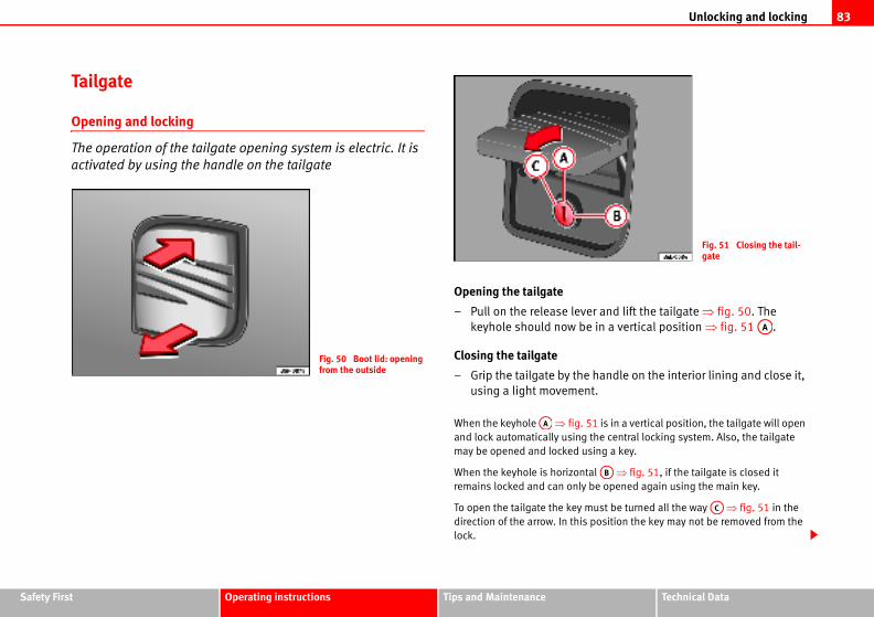
Unlocking and locking 83
Safety Fir Technical Data
er and lift the tailgate ⇒ fig. 50. The
e in a vertical position ⇒ fig. 51 .
handle on the interior lining and close it,
t.
51 is in a vertical position, the tailgate will open
the central locking system. Also, the tailgate
sing a key.
al ⇒ fig. 51, if the tailgate is closed it
be opened again using the main key.
ust be turned all the way ⇒ fig. 51 in the
position the key may not be removed from the
Fig. 51 Closing the tail-gate
AA
AB
AC
st Operating instructions Tips and Maintenance
Tailgate
Opening and locking
The operation of the tailgate opening system is electric. It is
activated by using the handle on the tailgate
Opening the tailgate
– Pull on the release lev
keyhole should now b
Closing the tailgate
– Grip the tailgate by the
using a light movemen
When the keyhole ⇒ fig.
and lock automatically using
may be opened and locked u
When the keyhole is horizont
remains locked and can only
To open the tailgate the key m
direction of the arrow. In this
lock.
Fig. 50 Boot lid: opening from the outside
AA
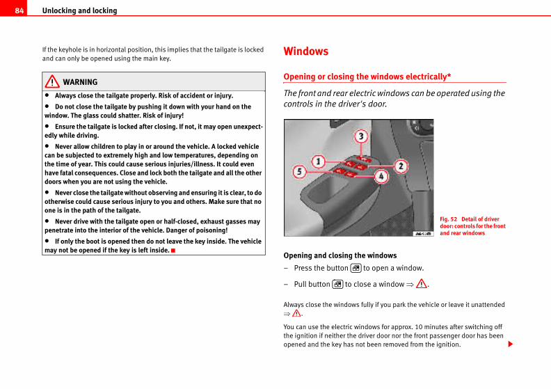
Unlocking and locking84
windows electrically*
ic windows can be operated using the
oor.
indows
open a window.
a window ⇒ .
y if you park the vehicle or leave it unattended
ws for approx. 10 minutes after switching off
r door nor the front passenger door has been
een removed from the ignition.
Fig. 52 Detail of driver door: controls for the front and rear windows
If the keyhole is in horizontal position, this implies that the tailgate is locked
and can only be opened using the main key.
WARNING
• Always close the tailgate properly. Risk of accident or injury.
• Do not close the tailgate by pushing it down with your hand on the window. The glass could shatter. Risk of injury!
• Ensure the tailgate is locked after closing. If not, it may open unexpect-edly while driving.
• Never allow children to play in or around the vehicle. A locked vehicle can be subjected to extremely high and low temperatures, depending on the time of year. This could cause serious injuries/illness. It could even have fatal consequences. Close and lock both the tailgate and all the other doors when you are not using the vehicle.
• Never close the tailgate without observing and ensuring it is clear, to do otherwise could cause serious injury to you and others. Make sure that no one is in the path of the tailgate.
• Never drive with the tailgate open or half-closed, exhaust gasses may penetrate into the interior of the vehicle. Danger of poisoning!
• If only the boot is opened then do not leave the key inside. The vehicle may not be opened if the key is left inside.
Windows
Opening or closing the
The front and rear electr
controls in the driver's d
Opening and closing the w
– Press the button to
– Pull button to close
Always close the windows full
⇒ .
You can use the electric windo
the ignition if neither the drive
opened and the key has not b
Unlocking and locking 85
Safety Fir Technical Data
ty switch to disable the rear electric windows. en disabled.
lose because it is stiff or because of an obstruc-
tically open again ⇒ page 86. If this happens,
not be closed before attempting to close it
closing*
and closing function is only possible
an only be activated from the driver's
he window briefly to the second position.
ly.
for the window briefly to the second posi-
s fully.
ing and closing
st Operating instructions Tips and Maintenance
Buttons in the driver door
Button for window in front left door
Button for window in front right door
Buttons for rear windows*
Safety switch for deactivating the electric window buttons in the rear
doors
Button for window in rear right door
Button for window in rear left door
Safety switch *
Safety switch in the driver door can be used to disable the electric window
buttons in the rear doors.
Safety switch not pressed: buttons on rear doors are activated.
Safety switch pressed: buttons on rear doors are deactivated.
WARNING
• Incorrect use of the electric windows can result in injury.
• Never close the tailgate without observing and ensuring it is clear, to do otherwise could cause serious injury to you and others. Make sure that no one is in the path of a window.
• Always take the vehicle key with you when you leave the vehicle.
• Never leave children or disabled persons in the vehicle, particularly if they have access to the keys. Unsupervised use of a key could mean that the engine is started or that electrical equipment is used (e.g. electric windows). Risk of accident. The doors can be locked using the remote control key. This could result in people being trapped in the vehicle in an emergency.
• The electric windows will work until the key has been removed from the ignition and one of the front doors has been opened.
• If necessary, use the safeMake sure that they have be
NoteIf the window is not able to c
tion, the window will automa
check why the window could
again.
One-touch opening and
The one-touch opening
on the front doors and c
door.
One-touch closing
– Pull up the button for t
The window closes ful
One-touch opening
– Push down the button
tion. The window open
Restoring one-touch open
– Close all windows.
A1
A2
A3
A4
A5
A3
WARNING (continued)
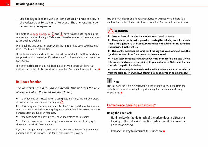
Unlocking and locking86
ll-back function will not work if there is a
dows. Contact an Authorised Service Centre.
ric windows can result in injury.
you when leaving the vehicle, even if you only ime. Please ensure that children are never left
work until the key has been removed from the doors has been opened.
ithout observing and ensuring it is clear, to do s injury to you and others. Make sure that no
w.
ain in the vehicle when you close the vehicle s cannot be opened even in an emergency.
ivated if the windows are closed from the
e ignition key for convenience closing
nd closing*
r lock of the driver door in either the
g position until all windows are either
rupt this function.
– Use the key to lock the vehicle from outside and hold the key in
the lock position for at least one second. The one-touch function
is now ready for operation.
The buttons ⇒ page 84, fig. 52 and have two levels for opening the
window and two for closing it. This makes it easier to open or close windows
to the desired position.
One-touch closing does not work when the ignition has been switched off,
even if the key is in the ignition.
The automatic open and close function will not work if the battery has been
temporarily disconnected, or if the battery is flat. The function then has to be
reactivated.
The one-touch function and roll-back function will not work if there is a
malfunction in the electric windows. Contact an Authorised Service Centre.
Roll-back function
The windows have a roll-back function. This reduces the risk
of injuries when the windows are closing.
• If a window is obstructed when closing automatically, the window stops
at this point and lowers immediately ⇒ .
• If this happens, check immediately (within 10 seconds) why the window
could not be closed before attempting to close it again. After 10 seconds the
normal automatic function resumes.
• If the window is still obstructed, the window stops at this point.
• If there is no obvious reason why the window cannot be closed, try to
close it again within five seconds.
If you wait longer than 5 - 10 seconds, the window will open fully when you
operate one of the buttons. One-touch closing is reactivated.
The one-touch function and ro
malfunction in the electric win
WARNING
• Incorrect use of the elect
• Always take the key with intend to be gone for a short tunsupervised in the vehicle.
• The electric windows willignition and one of the front
• Never close the tailgate wotherwise could cause seriouone is in the path of a windo
• Never allow people to remfrom the outside. The window
NoteThe roll-back function is deact
outside of the vehicle using th
⇒ page 86.
Convenience opening a
Using the door lock
– Hold the key in the doo
locking or the unlockin
opened or closed.
– Release the key to inter
A1 A2
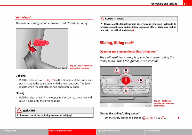
Unlocking and locking 87
Safety Fir Technical Data
ithout observing and ensuring it is clear, to do us injury to you and others. Make sure that no w.
f*
e sliding/tilting roof
oof is opened and closed using the
ignition is switched on.
sunroof
to position ⇒ fig. 54 ⇒ .
Fig. 54 Roof lining description: rotary sun roof control
AA
st Operating instructions Tips and Maintenance
Vent wings*
The rear vent wings can be opened and closed manually.
Opening
– Pull the release lever ⇒ fig. 53 in the direction of the arrow and
push it out at the same time until the lever engages. The lever
inserts when the deflector is half open or fully open.
Closing
– Pull the release lever in the opposite direction to the arrow and
push it back until the lever engages.
WARNING
• Incorrect use of the vent wings can result in injury!
• Never close the tailgate wotherwise could cause serioone is in the path of a windo
Sliding/tilting roo
Opening and closing th
The sliding/tilting sunr
rotary button when the
Closing the sliding/tilting
– Turn the rotary button
Fig. 53 Release lever for mechanical vent wing
WARNING (continued)
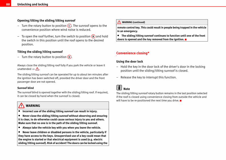
Unlocking and locking88
d result in people being trapped in the vehicle
f continues to function until one of the front removed from the ignition.
r lock of the driver's door in the locking
g/tilting sunroof is closed.
rupt this function.
ry button remains in the last position selected
venience closing from outside the vehicle and
he next time you drive.
Opening/tilting the sliding/tilting sunroof
– Turn the rotary button to position . The sunroof opens to the
convenience position where wind noise is reduced.
– To open the roof further, turn the switch to position and hold
the switch in this position until the roof opens to the desired
position.
Tilting the sliding/tilting sunroof
– Turn the rotary button to position .
Always close the sliding/tilting roof fully if you park the vehicle or leave it
unattended ⇒ .
The sliding/tilting sunroof can be operated for up to about ten minutes after
the ignition has been switched off, provided the driver door and the front
passenger door are not opened.
Sunroof blind
The sunroof blind is opened together with the sliding/tilting roof. If required,
it can be closed by hand when the sunroof is closed.
WARNING
• Incorrect use of the sliding/tilting sunroof can result in injury.
• Never close the sliding/tilting sunroof without observing and ensuring it is clear, to do otherwise could cause serious injury to you and others. Make sure that no one is in the path of the sliding/tilting sunroof.
• Always take the vehicle key with you when you leave the vehicle.
• Never leave children or disabled persons in the vehicle, particularly if they have access to the keys. Unsupervised use of a key could mean that the engine is started or that electrical equipment is used (e.g. electric sliding/tilting sunroof). Risk of accident! The doors can be locked using the
remote control key. This coulin an emergency.
• The sliding/tilting sunroodoors is opened and the key
Convenience closing*
Using the door lock
– Hold the key in the doo
position until the slidin
– Release the key to inter
NoteThe sliding/tilting sunroof rota
if the roof is closed using con
will have to be re-positioned t
AC
AB
AD
WARNING (continued)
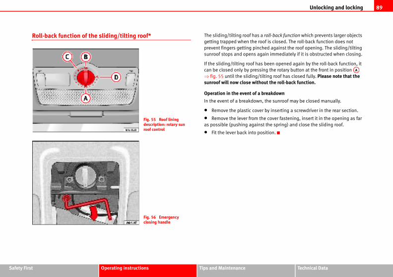
Unlocking and locking 89
Safety Fir Technical Data
roll-back function which prevents larger objects
f is closed. The roll-back function does not
ed against the roof opening. The sliding/tilting
in immediately if it is obstructed when closing.
been opened again by the roll-back function, it
g the rotary button at the front in position
ting roof has closed fully. Please note that the ut the roll-back function.
reakdown
the sunroof may be closed manually.
by inserting a screwdriver in the rear section.
e cover fastening, insert it in the opening as far
the spring) and close the sliding roof.
ition.
AA
st Operating instructions Tips and Maintenance
Roll-back function of the sliding/tilting roof* The sliding/tilting roof has a
getting trapped when the roo
prevent fingers getting pinch
sunroof stops and opens aga
If the sliding/tilting roof has
can be closed only by pressin
⇒ fig. 55 until the sliding/til
sunroof will now close witho
Operation in the event of a b
In the event of a breakdown,
• Remove the plastic cover
• Remove the lever from th
as possible (pushing against
• Fit the lever back into pos
Fig. 55 Roof lining description: rotary sun roof control
Fig. 56 Emergency closing handle
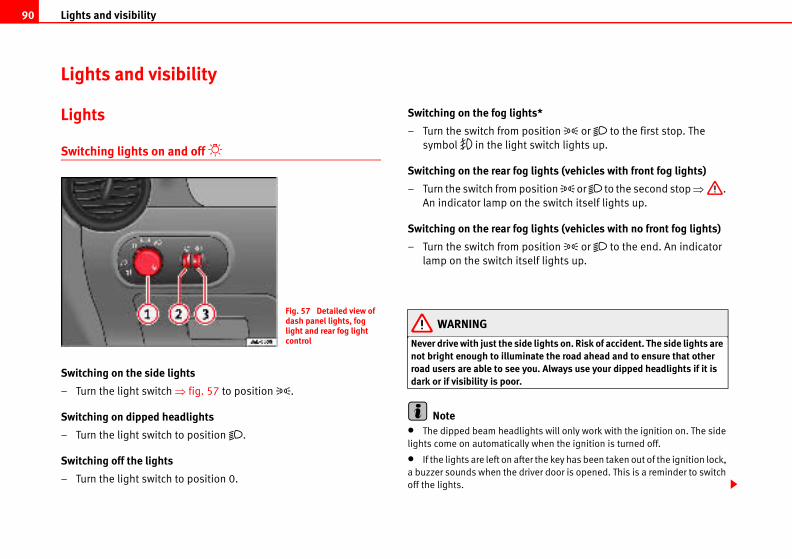
Lights and visibility90
s*
sition or to the first stop. The
witch lights up.
lights (vehicles with front fog lights)
sition or to the second stop ⇒ .
e switch itself lights up.
lights (vehicles with no front fog lights)
sition or to the end. An indicator
lf lights up.
lights on. Risk of accident. The side lights are te the road ahead and to ensure that other
u. Always use your dipped headlights if it is
ts will only work with the ignition on. The side
when the ignition is turned off.
the key has been taken out of the ignition lock,
er door is opened. This is a reminder to switch
Lights and visibility
Lights
Switching lights on and off
Switching on the side lights
– Turn the light switch ⇒ fig. 57 to position .
Switching on dipped headlights
– Turn the light switch to position .
Switching off the lights
– Turn the light switch to position 0.
Switching on the fog light
– Turn the switch from po
symbol in the light s
Switching on the rear fog
– Turn the switch from po
An indicator lamp on th
Switching on the rear fog
– Turn the switch from po
lamp on the switch itse
WARNING
Never drive with just the sidenot bright enough to illuminaroad users are able to see yodark or if visibility is poor.
Note• The dipped beam headligh
lights come on automatically
• If the lights are left on after
a buzzer sounds when the driv
off the lights.
Fig. 57 Detailed view of dash panel lights, fog light and rear fog light control
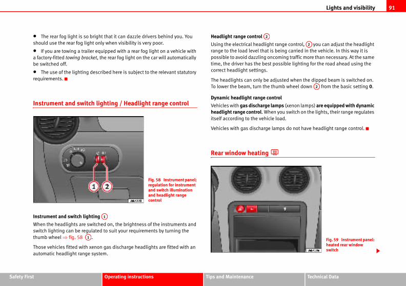
Lights and visibility 91
Safety Fir Technical Data
t range control, you can adjust the headlight
being carried in the vehicle. In this way it is
coming traffic more than necessary. At the same
possible lighting for the road ahead using the
djusted when the dipped beam is switched on.
humb wheel down from the basic setting 0.
trol
amps (xenon lamps) are equipped with dynamic n you switch on the lights, their range regulates
load.
amps do not have headlight range control.
A2
A2
Fig. 59 Instrument panel: heated rear window switch
st Operating instructions Tips and Maintenance
• The rear fog light is so bright that it can dazzle drivers behind you. You
should use the rear fog light only when visibility is very poor.
• If you are towing a trailer equipped with a rear fog light on a vehicle with
a factory-fitted towing bracket, the rear fog light on the car will automatically
be switched off.
• The use of the lighting described here is subject to the relevant statutory
requirements.
Instrument and switch lighting / Headlight range control
Instrument and switch lighting
When the headlights are switched on, the brightness of the instruments and
switch lighting can be regulated to suit your requirements by turning the
thumb wheel ⇒ fig. 58 .
Those vehicles fitted with xenon gas discharge headlights are fitted with an
automatic headlight range system.
Headlight range control
Using the electrical headligh
range to the load level that is
possible to avoid dazzling on
time, the driver has the best
correct headlight settings.
The headlights can only be a
To lower the beam, turn the t
Dynamic headlight range con
Vehicles with gas discharge lheadlight range control. Whe
itself according to the vehicle
Vehicles with gas discharge l
Rear window heating
Fig. 58 Instrument panel: regulation for instrument and switch illumination and headlight range control
A1
A1
A2
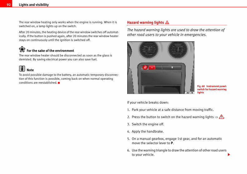
Lights and visibility92
ts are used to draw the attention of
r vehicle in emergencies.
n:
afe distance from moving traffic.
tch on the hazard warning lights ⇒ .
ngage 1st gear, and for an automatic
to P.
e to draw the attention of other road users
Fig. 60 Instrument panel: switch for hazard warning lights
The rear window heating only works when the engine is running. When it is
switched on, a lamp lights up on the switch.
After 20 minutes, the heating device of the rear window switches off automat-
ically. If the button is pushed again, after 20 minutes the rear window heater
stays on continuously until the ignition is switched off.
For the sake of the environmentThe rear window heater should be disconnected as soon as the glass is
demisted. By saving electrical power you can also save fuel.
NoteTo avoid possible damage to the battery, an automatic temporary disconnec-
tion of this function is possible, coming back on when normal operating
conditions are reestablished.
Hazard warning lights
The hazard warning ligh
other road users to you
If your vehicle breaks dow
1. Park your vehicle at a s
2. Press the button to swi
3. Switch the engine off.
4. Apply the handbrake.
5. On a manual gearbox, e
move the selector lever
6. Use the warning triangl
to your vehicle.
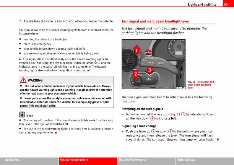
Lights and visibility 93
Safety Fir Technical Data
eam headlight lever
in beam lever also operates the
headlight flasher.
beam headlight lever has the following
nals
ay up ⇒ fig. 61 to indicate right, and
indicate left.
r down to the point where you incur
lease the lever. The turn signal will flash
esponding warning lamp will also flash.
Fig. 61 Turn signal and main beam headlight lever
A1
A2
st Operating instructions Tips and Maintenance
7. Always take the vehicle key with you when you leave the vehicle.
You should switch on the hazard warning lights to warn other road users, for
instance when:
• reaching the tail end of a traffic jam
• there is an emergency
• your vehicle breaks down due to a technical defect
• you are towing another vehicle or your vehicle is being towed.
All turn signals flash simultaneously when the hazard warning lights are
switched on. That is that the two turn signal indicator lamps and the
indicator lamp in the switch will flash at the same time. The hazard
warning lights also work when the ignition is switched off.
WARNING
• The risk of an accident increases if your vehicle breaks down. Always use the hazard warning lights and a warning triangle to draw the attention of other road users to your stationary vehicle.
• Never park where the catalytic converter could come into contact with inflammable materials under the vehicle, for example dry grass or spilt petrol. This could start a fire!
Note• The battery will run down if the hazard warning lights are left on for a long
time, even if the ignition is switched off.
• The use of the hazard warning lights described here is subject to the rele-
vant statutory requirements.
Turn signal and main b
The turn signal and ma
parking lights and the
The turn signal and main
functions:
Switching on the turn sig
– Move the lever all the w
all the way down to
Signalling a lane change
– Push the lever up o
resistance and then re
several times. The corr
A2
A1
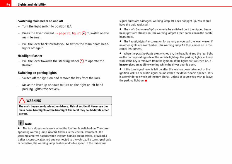
Lights and visibility94
rning lamp does not light up. You should
can only be switched on if the dipped beam
warning lamp then comes on in the combi-
es on for as long as you pull the lever – even if
n. The warning lamp then comes on in the
e switched on, the headlight and the rear light
he vehicle light up. The parking lights will only
the ignition. If the lights are switched on, a
ng while the driver door is open.
ft on after the key has been taken out of the
al sounds when the driver door is opened. This
turn signal, unless of course you wish to leave
Switching main beam on and off
– Turn the light switch to position .
– Press the lever forward ⇒ page 93, fig. 61 to switch on the
main beams.
– Pull the lever back towards you to switch the main beam head-
lights off again.
Headlight flasher
– Pull the lever towards the steering wheel to operate the
flasher.
Switching on parking lights
– Switch off the ignition and remove the key from the lock.
– Move the lever up or down to turn on the right or left-hand
parking lights respectively.
WARNING
The main beam can dazzle other drivers. Risk of accident! Never use the main beam headlights or the headlight flasher if they could dazzle other drivers.
Note• The turn signals only work when the ignition is switched on. The corre-
sponding warning lamp or flashes in the combi-instrument. The
warning lamp flashes when the turn signals are operated, provided a
trailer is correctly attached and connected to the vehicle. If a turn signal bulb
is defective, the warning lamp flashes at double speed. If the trailer turn
signal bulbs are damaged, wa
have the bulb replaced.
• The main beam headlights
headlights are already on. The
instrument.
• The headlight flasher com
no other lights are switched o
combi-instrument.
• When the parking lights ar
on the corresponding side of t
work if the key is removed from
buzzer gives an audible warni
• If the turn signal lever is le
ignition lock, an acoustic sign
is a reminder to switch off the
the parking light on.
A4
A3
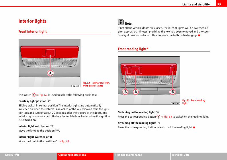
Lights and visibility 95
Safety Fir Technical Data
e closed, the interior lights will be switched off
viding the key has been removed and the cour-
his prevents the battery discharging.
t
on ⇒ fig. 63 to switch on the reading light.
hts
on to switch off the reading light.
Fig. 63 Front reading light
AB
st Operating instructions Tips and Maintenance
Interior lights
Front interior light
The switch ⇒ fig. 62 is used to select the following positions:
Courtesy light position
Sliding switch in central position The interior lights are automatically
switched on when the vehicle is unlocked or the key removed from the igni-
tion lock and turn off about 20 seconds after the closure of the doors. The
interior lights are switched off when the vehicle is locked or when the ignition
is switched on.
Interior light switched on
Move the knob to the position .
Interior light switched off O
Move the knob to the position O ⇒ fig. 62.
NoteIf not all the vehicle doors ar
after approx. 10 minutes, pro
tesy light position selected. T
Front reading light*
Switching on the reading ligh
Press the corresponding butt
Switching off the reading lig
Press the corresponding butt
Fig. 62 Interior roof trim: front interior lights
AA
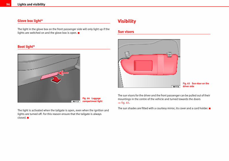
Lights and visibility96
d the front passenger can be pulled out of their
vehicle and turned towards the doors
a courtesy mirror, its cover and a card holder.
Fig. 65 Sun visor on the driver side
Glove box light*
The light in the glove box on the front passenger side will only light up if the
lights are switched on and the glove box is open.
Boot light*
The light is activated when the tailgate is open, even when the ignition and
lights are turned off. For this reason ensure that the tailgate is always
closed.
Visibility
Sun visors
The sun visors for the driver an
mountings in the centre of the
⇒ fig. 65.
The sun shades are fitted with
Fig. 64 Luggage compartment light
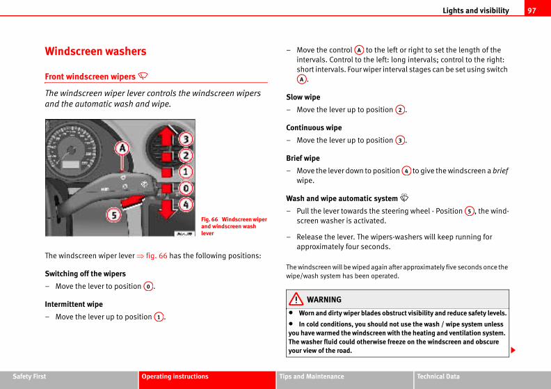
Lights and visibility 97
Safety Fir Technical Data
the left or right to set the length of the
e left: long intervals; control to the right:
per interval stages can be set using switch
osition .
osition .
position to give the windscreen a brief
system
he steering wheel - Position , the wind-
ated.
wipers-washers will keep running for
onds.
again after approximately five seconds once the
operated.
des obstruct visibility and reduce safety levels.
hould not use the wash / wipe system unless creen with the heating and ventilation system. rwise freeze on the windscreen and obscure
A2
A3
A4
A5
st Operating instructions Tips and Maintenance
Windscreen washers
Front windscreen wipers
The windscreen wiper lever controls the windscreen wipers
and the automatic wash and wipe.
The windscreen wiper lever ⇒ fig. 66 has the following positions:
Switching off the wipers
– Move the lever to position .
Intermittent wipe
– Move the lever up to position .
– Move the control to
intervals. Control to th
short intervals. Four wi
.
Slow wipe
– Move the lever up to p
Continuous wipe
– Move the lever up to p
Brief wipe
– Move the lever down to
wipe.
Wash and wipe automatic
– Pull the lever towards t
screen washer is activ
– Release the lever. The
approximately four sec
The windscreen will be wiped
wipe/wash system has been
WARNING
• Worn and dirty wiper bla
• In cold conditions, you syou have warmed the windsThe washer fluid could otheyour view of the road.
Fig. 66 Windscreen wiper and windscreen wash lever
A0
A1
AA
AA

Lights and visibility98
the frequency of the windscreen
ing on the amount of rain.
or
iper lever into position ⇒ fig. 67.
the left or right to set the sensitivity of the
he right: highly sensitive. Control to the
nterval wipe function. You will have to switch
witch off the ignition. This is done by switching
off and back on.
Fig. 67 Windscreen wiper lever
A1
• Always note the corresponding warnings on ⇒ page 190.
CautionIn icy conditions, always check that the wiper blades are not frozen to the
glass before using the wipers for the first time. If you switch on the wipers
when the wiper blades are frozen to the windscreen, you could damage both
the wiper blades and the wiper motor.
Note• The windscreen wipers will only work when the ignition is switched on.
• The heat output of the heated jets* is controlled automatically when the
ignition is switched on, depending upon the outside temperature.
Rain sensor*
The rain sensor controls
wiper intervals, depend
Switching on the rain sens
– Move the windscreen w
– Move the control to
rain sensor. Control to t
left: less sensitive.
The rain sensor is part of the i
the rain sensor back on if you s
the wiper intermittent function
WARNING (continued)
AA
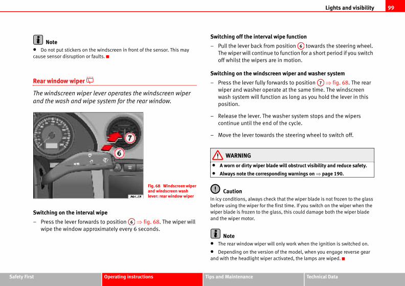
Lights and visibility 99
Safety Fir Technical Data
wipe function
position towards the steering wheel.
to function for a short period if you switch
re in motion.
een wiper and washer system
rwards to position ⇒ fig. 68. The rear
rate at the same time. The windscreen
ion as long as you hold the lever in this
washer system stops and the wipers
of the cycle.
s the steering wheel to switch off.
de will obstruct visibility and reduce safety.
onding warnings on ⇒ page 190.
k that the wiper blade is not frozen to the glass
first time. If you switch on the wiper when the
lass, this could damage both the wiper blade
ll only work when the ignition is switched on.
of the model, when you engage reverse gear
activated, the lamps are wiped.
A6
A7
st Operating instructions Tips and Maintenance
Note• Do not put stickers on the windscreen in front of the sensor. This may
cause sensor disruption or faults.
Rear window wiper
The windscreen wiper lever operates the windscreen wiper
and the wash and wipe system for the rear window.
Switching on the interval wipe
– Press the lever forwards to position ⇒ fig. 68. The wiper will
wipe the window approximately every 6 seconds.
Switching off the interval
– Pull the lever back from
The wiper will continue
off whilst the wipers a
Switching on the windscr
– Press the lever fully fo
wiper and washer ope
wash system will funct
position.
– Release the lever. The
continue until the end
– Move the lever toward
WARNING
• A worn or dirty wiper bla
• Always note the corresp
CautionIn icy conditions, always chec
before using the wiper for the
wiper blade is frozen to the g
and the wiper motor.
Note• The rear window wiper wi
• Depending on the version
and with the headlight wiper
Fig. 68 Windscreen wiper and windscreen wash lever: rear window wiper
A6
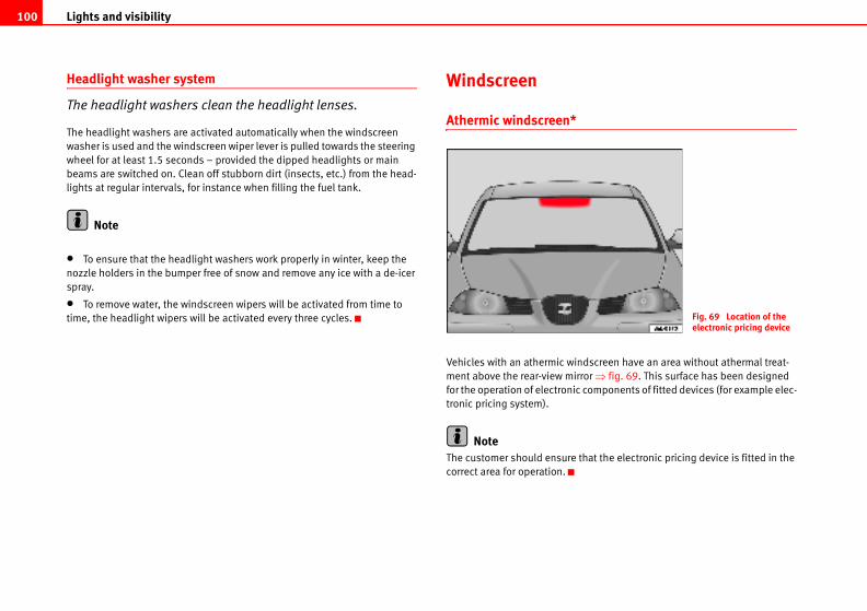
Lights and visibility100
dscreen have an area without athermal treat-
or ⇒ fig. 69. This surface has been designed
components of fitted devices (for example elec-
hat the electronic pricing device is fitted in the
Fig. 69 Location of the electronic pricing device
Headlight washer system
The headlight washers clean the headlight lenses.
The headlight washers are activated automatically when the windscreen
washer is used and the windscreen wiper lever is pulled towards the steering
wheel for at least 1.5 seconds – provided the dipped headlights or main
beams are switched on. Clean off stubborn dirt (insects, etc.) from the head-
lights at regular intervals, for instance when filling the fuel tank.
Note
• To ensure that the headlight washers work properly in winter, keep the
nozzle holders in the bumper free of snow and remove any ice with a de-icer
spray.
• To remove water, the windscreen wipers will be activated from time to
time, the headlight wipers will be activated every three cycles.
Windscreen
Athermic windscreen*
Vehicles with an athermic win
ment above the rear-view mirr
for the operation of electronic
tronic pricing system).
NoteThe customer should ensure t
correct area for operation.
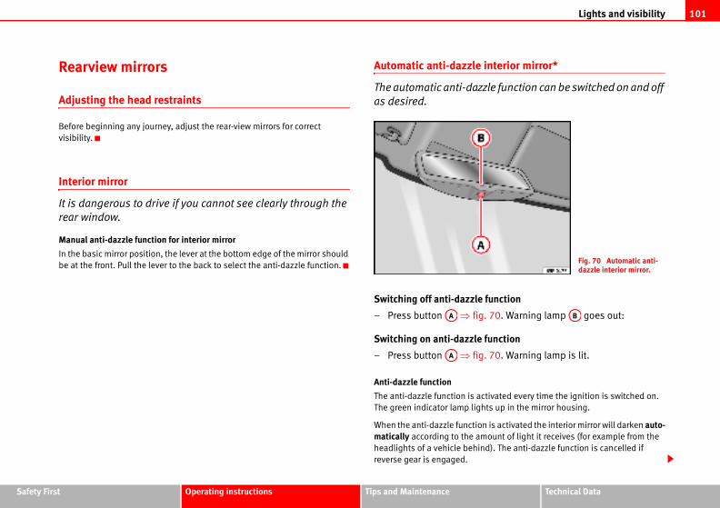
Lights and visibility 101
Safety Fir Technical Data
interior mirror*
zle function can be switched on and off
function
. 70. Warning lamp goes out:
function
. 70. Warning lamp is lit.
tivated every time the ignition is switched on.
ts up in the mirror housing.
is activated the interior mirror will darken auto-ount of light it receives (for example from the
d). The anti-dazzle function is cancelled if
Fig. 70 Automatic anti-dazzle interior mirror.
AB
st Operating instructions Tips and Maintenance
Rearview mirrors
Adjusting the head restraints
Before beginning any journey, adjust the rear-view mirrors for correct
visibility.
Interior mirror
It is dangerous to drive if you cannot see clearly through the
rear window.
Manual anti-dazzle function for interior mirror
In the basic mirror position, the lever at the bottom edge of the mirror should
be at the front. Pull the lever to the back to select the anti-dazzle function.
Automatic anti-dazzle
The automatic anti-daz
as desired.
Switching off anti-dazzle
– Press button ⇒ fig
Switching on anti-dazzle
– Press button ⇒ fig
Anti-dazzle function
The anti-dazzle function is ac
The green indicator lamp ligh
When the anti-dazzle function
matically according to the am
headlights of a vehicle behin
reverse gear is engaged.
AA
AA
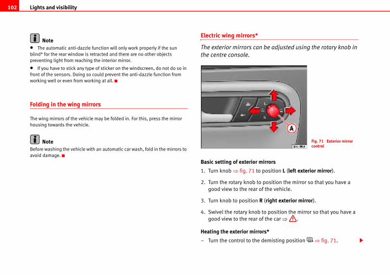
Lights and visibility102
be adjusted using the rotary knob in
irrors
position L (left exterior mirror).
position the mirror so that you have a
f the vehicle.
(right exterior mirror).
to position the mirror so that you have a
f the car ⇒ .
rs*
emisting position ⇒ fig. 71.
Fig. 71 Exterior mirror control
Note• The automatic anti-dazzle function will only work properly if the sun
blind* for the rear window is retracted and there are no other objects
preventing light from reaching the interior mirror.
• If you have to stick any type of sticker on the windscreen, do not do so in
front of the sensors. Doing so could prevent the anti-dazzle function from
working well or even from working at all.
Folding in the wing mirrors
The wing mirrors of the vehicle may be folded in. For this, press the mirror
housing towards the vehicle.
NoteBefore washing the vehicle with an automatic car wash, fold in the mirrors to
avoid damage.
Electric wing mirrors*
The exterior mirrors can
the centre console.
Basic setting of exterior m
1. Turn knob ⇒ fig. 71 to
2. Turn the rotary knob to
good view to the rear o
3. Turn knob to position R
4. Swivel the rotary knob
good view to the rear o
Heating the exterior mirro
– Turn the control to the d
Lights and visibility 103
Safety Fir Technical Data
nvironmentould be switched off when it is no longer
wise.
t ever fails to operate, the mirrors can be
ressing the edge of the mirror glass.
ing mirrors, the following points should be
al force (e.g. a knock while manoeuvring), the
sing is altered, the mirror will have to be
. Do not readjust the mirror housing by hand, as
rror adjuster function.
be adjusted separately or simultaneously, as
st Operating instructions Tips and Maintenance
– Place the control in position L or R once the mirrors have
demisted to prevent unnecessary use of the battery.
Folding in exterior mirrors*
– Turn the control ⇒ page 102, fig. 71 to position to fold in the
exterior mirrors. You should always fold in the exterior mirrors if
you are driving through an automatic car wash. This will help
prevent damage.
Folding exterior mirrors back out to the extended position*
– Turn the knob to position L or R to fold the exterior mirrors back
out ⇒ .
Synchronised wing mirror adjustment*
1. Turn the control to the position L (left exterior mirror).
2. Turn the rotary knob to position the mirror so that you have a
good view to the rear of the vehicle. The right exterior mirror will
be adjusted at the same time (synchronised).
WARNING
• The rear view convex or aspheric mirror increase the field of vision however the objects appear smaller and further away in the mirrors. If you use these mirrors to estimate the distance to vehicles behind you when changing lane, you could make a mistake. Risk of accident.
• If possible, use the interior mirror to estimate distances to vehicles behind you.
• Make sure that you do not get your finger trapped between the mirror and the mirror base when folding back the mirrors. Risk of injury!
For the sake of the eThe exterior mirror heating sh
needed. Fuel is wasted other
Note• If the electrical adjustmen
adjusted by hand by lightly p
• In vehicles with electric w
observed: if, due to an extern
adjustment of the mirror hou
completely folded electricallythis will interfere with the mi
• The rear view mirrors can
described before.
Seats and stowage104
he foot well when the vehicle is moving; never out of the window or on the seat. This also correct sitting position exposes you to an event of a braking manoeuvre or an accident. could sustain severe injuries due to an incor-
er and front passenger to maintain a distance ering wheel or dash panel. Failure to respect
s that the airbag will not protect you. Risk of ween the driver and the steering wheel or and the dash panel should always be as great
passenger seat only when the vehicle is at could move unexpectedly while the vehicle e the risk of an accident and therefore injury. our seat, you will assume an incorrect sitting
nts.
to installing a child seat on the front ling a child seat, observe the warning note in ”.
Seats and stowage
The importance of correct seat adjustment
Proper seat adjustment optimises the level of protection
offered by seat belts and airbags.
Your vehicle has five passenger places, two individual front seats and three
places on the rear seat. Each seat is equipped with a three-point seat belt.
The driver seat and front passenger seat can be adjusted in many ways to suit
the physical requirements of the vehicle occupants. The correct seat position
is very important for:
• fast and easy operation of all controls on the instrument panel,
• relaxed posture that does not cause drowsiness,
• safe driving ⇒ page 7,
• and to ensure that the seat belts and airbag system provide maximum
protection ⇒ page 16.
WARNING
• If the driver and passengers assume improper sitting positions, they may sustain critical injuries.
• Never transport more people than there are seats available in the vehicle.
• Every occupant in the vehicle must properly fasten and wear the seat belt belonging to his or her seat. Children must be protected with an appro-priate child restraint system ⇒ page 42, “Child safety”.
• The front seats and all head restraints must always be adjusted to body size and the seat belt must always be properly adjusted to provide you and your passengers with optimum protection.
• Always keep your feet in trest them on the dash panel,applies to passengers. An inincreased risk of injury in theIf the airbag is triggered, yourect sitting position.
• It is important for the drivof at least 25 cm from the stethe minimum distance meanfatal injury. The distance betbetween the front passengeras possible.
• Adjust the driver or front stationary. Otherwise your seis moving. This could increasIn addition, while adjusting yposition. Risk of fatal accide
• Special guidelines apply passenger seat. When instalthe ⇒ page 42, “Child safety
WARNING (continued)
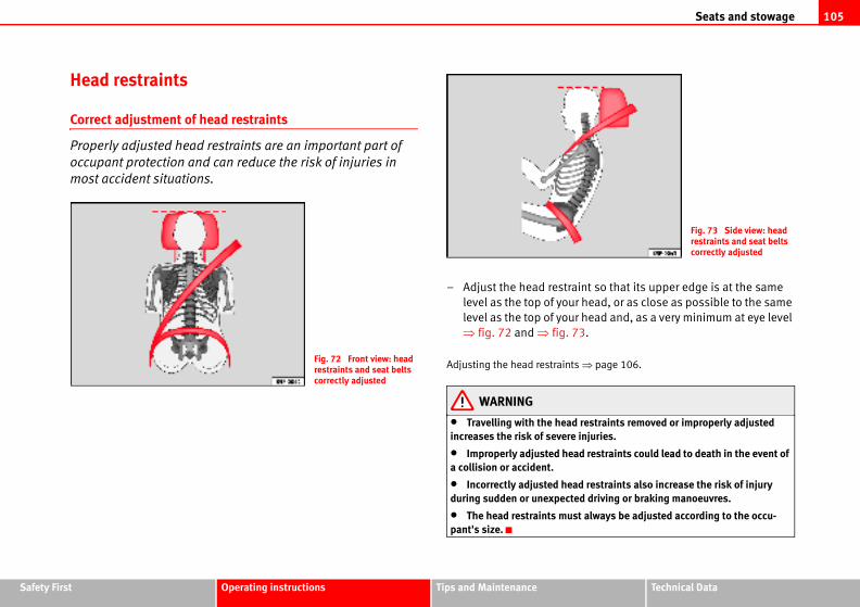
Seats and stowage 105
Safety Fir Technical Data
int so that its upper edge is at the same
head, or as close as possible to the same
head and, as a very minimum at eye level
3.
⇒ page 106.
restraints removed or improperly adjusted injuries.
d restraints could lead to death in the event of
d restraints also increase the risk of injury d driving or braking manoeuvres.
t always be adjusted according to the occu-
Fig. 73 Side view: head restraints and seat belts correctly adjusted
st Operating instructions Tips and Maintenance
Head restraints
Correct adjustment of head restraints
Properly adjusted head restraints are an important part of
occupant protection and can reduce the risk of injuries in
most accident situations.
– Adjust the head restra
level as the top of your
level as the top of your
⇒ fig. 72 and ⇒ fig. 7
Adjusting the head restraints
WARNING
• Travelling with the headincreases the risk of severe
• Improperly adjusted heaa collision or accident.
• Incorrectly adjusted headuring sudden or unexpecte
• The head restraints muspant's size.
Fig. 72 Front view: head restraints and seat belts correctly adjusted
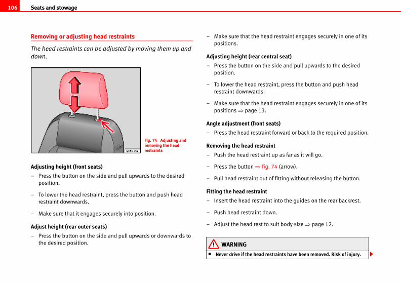
Seats and stowage106
d restraint engages securely in one of its
tral seat)
side and pull upwards to the desired
aint, press the button and push head
d restraint engages securely in one of its
ats)
t forward or back to the required position.
int
up as far as it will go.
74 (arrow).
of fitting without releasing the button.
t into the guides on the rear backrest.
wn.
suit body size ⇒ page 12.
straints have been removed. Risk of injury.
Removing or adjusting head restraints
The head restraints can be adjusted by moving them up and
down.
Adjusting height (front seats)
– Press the button on the side and pull upwards to the desired
position.
– To lower the head restraint, press the button and push head
restraint downwards.
– Make sure that it engages securely into position.
Adjust height (rear outer seats)
– Press the button on the side and pull upwards or downwards to
the desired position.
– Make sure that the hea
positions.
Adjusting height (rear cen
– Press the button on the
position.
– To lower the head restr
restraint downwards.
– Make sure that the hea
positions ⇒ page 13.
Angle adjustment (front se
– Press the head restrain
Removing the head restra
– Push the head restraint
– Press the button ⇒ fig.
– Pull head restraint out
Fitting the head restraint
– Insert the head restrain
– Push head restraint do
– Adjust the head rest to
WARNING
• Never drive if the head re
Fig. 74 Adjusting and removing the head restraints
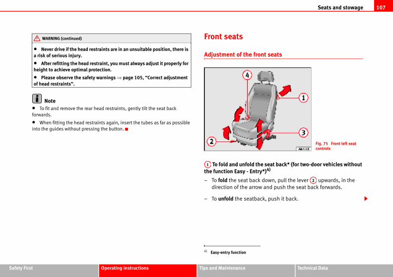
Seats and stowage 107
Safety Fir Technical Data
t seats
seat back* (for two-door vehicles without )4)
own, pull the lever upwards, in the
and push the seat back forwards.
, push it back.
Fig. 75 Front left seat controls
A2
st Operating instructions Tips and Maintenance
• Never drive if the head restraints are in an unsuitable position, there is a risk of serious injury.
• After refitting the head restraint, you must always adjust it properly for height to achieve optimal protection.
• Please observe the safety warnings ⇒ page 105, “Correct adjustment of head restraints”.
Note• To fit and remove the rear head restraints, gently tilt the seat back
forwards.
• When fitting the head restraints again, insert the tubes as far as possible
into the guides without pressing the button.
Front seats
Adjustment of the fron
To fold and unfold thethe function Easy - Entry*
– To fold the seat back d
direction of the arrow
– To unfold the seatback
WARNING (continued)
4) Easy-entry function
A1
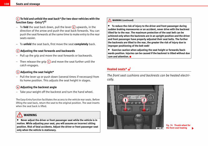
Seats and stowage108
y to the driver and front passenger during or an accident, never drive with the backrest imum protection of the seat belt can be rests are in an upright position and the driver perly adjusted their seat belts. The further
e rear, the greater the risk of injury due to elt web!
justing the seat height or forwards/back-e caused if the backrest is tilted without due
and backrests can be heated electri-
Fig. 76 Thumb wheel for the front seat heating
To fold and unfold the seat back* (for two-door vehicles with the function Easy - Entry*)4)
– To fold the seat back down, pull the lever upwards, in the
direction of the arrow and push the seat back forwards. You can
push the seat forwards at the same time to make entry to the rear
seats easier.
– To unfold the seat back, first move the seat completely back.
Adjusting the seat forwards and backwards
– Pull up the grip and move the seat forwards or backwards.
– Then release the grip and move the seat further until the
catch engages.
Adjusting the seat height*
– Pull the lever up or push down (several times if necessary) from
its home position. This adjusts the seat height in stages.
Adjusting the backrest angle
– Take your weight off the backrest and turn the hand wheel.
The Easy-Entry function facilitates the access to the vehicle rear seats. Before
lifting the seat back, return the seat to the original position. The seat inserts
when the seat back is lifted.
WARNING
• Never adjust the driver or front passenger seat while the vehicle is in motion. While adjusting your seat, you will assume an incorrect sitting position. Risk of fatal accidents. Adjust the driver or front passenger seat only when the vehicle is stationary.
• To reduce the risk of injursudden braking manoeuvrestilted far to the rear. The maxachieved only when the backand front passenger have prothe backrests are tilted to thimproper positioning of the b
• Exercise caution when adwards position. Injuries can bcare and attention.
Heated seats*
The front seat cushions
cally.
A1
A2
A2
A1
A3
A4
WARNING (continued)
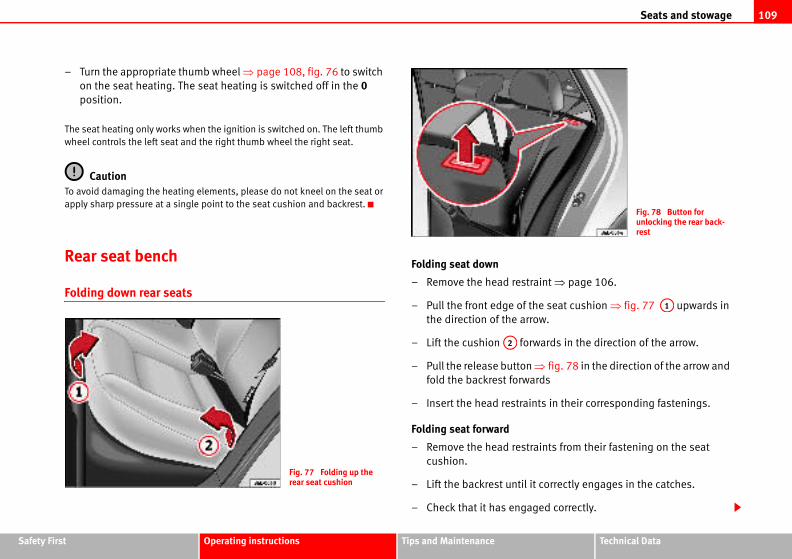
Seats and stowage 109
Safety Fir Technical Data
aint ⇒ page 106.
he seat cushion ⇒ fig. 77 upwards in
ow.
wards in the direction of the arrow.
⇒ fig. 78 in the direction of the arrow and
rds
nts in their corresponding fastenings.
aints from their fastening on the seat
t correctly engages in the catches.
ged correctly.
Fig. 78 Button for unlocking the rear back-rest
A1
st Operating instructions Tips and Maintenance
– Turn the appropriate thumb wheel ⇒ page 108, fig. 76 to switch
on the seat heating. The seat heating is switched off in the 0
position.
The seat heating only works when the ignition is switched on. The left thumb
wheel controls the left seat and the right thumb wheel the right seat.
CautionTo avoid damaging the heating elements, please do not kneel on the seat or
apply sharp pressure at a single point to the seat cushion and backrest.
Rear seat bench
Folding down rear seats
Folding seat down
– Remove the head restr
– Pull the front edge of t
the direction of the arr
– Lift the cushion for
– Pull the release button
fold the backrest forwa
– Insert the head restrai
Folding seat forward
– Remove the head restr
cushion.
– Lift the backrest until i
– Check that it has enga
Fig. 77 Folding up the rear seat cushion
A2
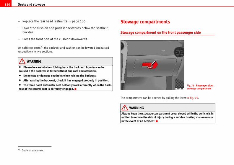
Seats and stowage110
ments
on the front passenger side
ed by pulling the lever ⇒ fig. 79.
partment cover closed while the vehicle is in njury during a sudden braking manoeuvre or
Fig. 79 Passenger side: stowage compartment
– Replace the rear head restraints ⇒ page 106.
– Lower the cushion and push it backwards below the seatbelt
buckles.
– Press the front part of the cushion downwards.
On split rear seats 5) the backrest and cushion can be lowered and raised
respectively in two sections.
WARNING
• Please be careful when folding back the backrest! Injuries can be caused if the backrest is tilted without due care and attention.
• Do no trap or damage seatbelts when raising the backrest.
• After raising the backrest, check it has engaged properly in position.
• The three point automatic seat belt only works correctly when the back-rest of the central seat is correctly engaged.
Stowage compart
Stowage compartment
The compartment can be open
WARNING
Always keep the stowage commotion to reduce the risk of iin the event of an accident.
5) Optional equipment
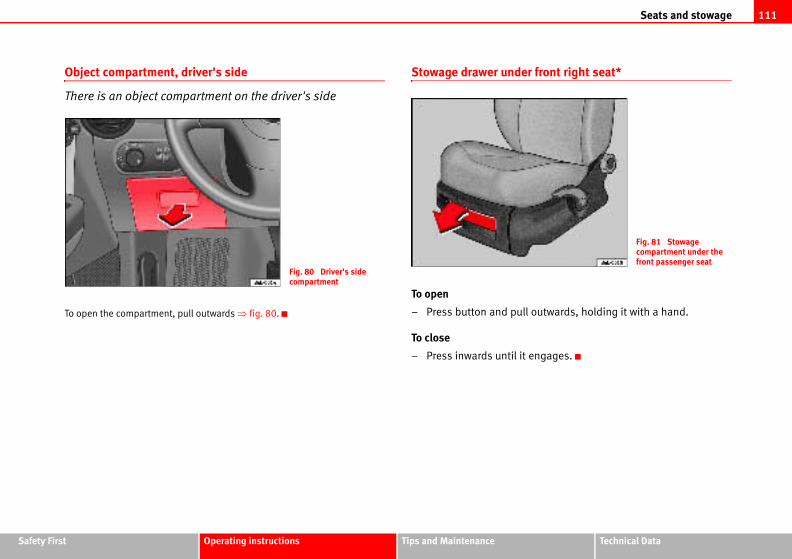
Seats and stowage 111
Safety Fir Technical Data
front right seat*
outwards, holding it with a hand.
ngages.
Fig. 81 Stowage compartment under the front passenger seat
st Operating instructions Tips and Maintenance
Object compartment, driver's side
There is an object compartment on the driver's side
To open the compartment, pull outwards ⇒ fig. 80.
Stowage drawer under
To open
– Press button and pull
To close
– Press inwards until it e
Fig. 80 Driver's side compartment
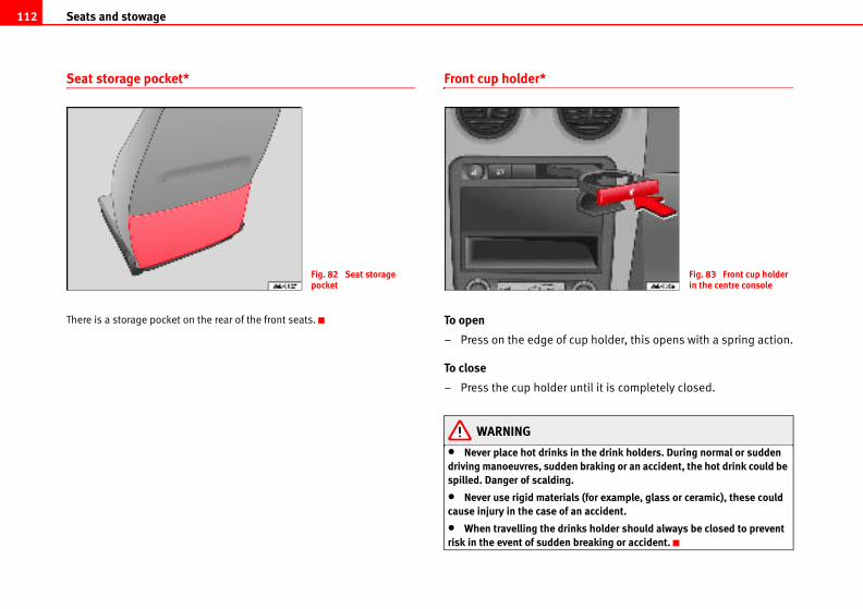
Seats and stowage112
p holder, this opens with a spring action.
til it is completely closed.
the drink holders. During normal or sudden braking or an accident, the hot drink could be
(for example, glass or ceramic), these could accident.
s holder should always be closed to prevent reaking or accident.
Fig. 83 Front cup holder in the centre console
Seat storage pocket*
There is a storage pocket on the rear of the front seats.
Front cup holder*
To open
– Press on the edge of cu
To close
– Press the cup holder un
WARNING
• Never place hot drinks indriving manoeuvres, sudden spilled. Danger of scalding.
• Never use rigid materialscause injury in the case of an
• When travelling the drinkrisk in the event of sudden b
Fig. 82 Seat storage pocket
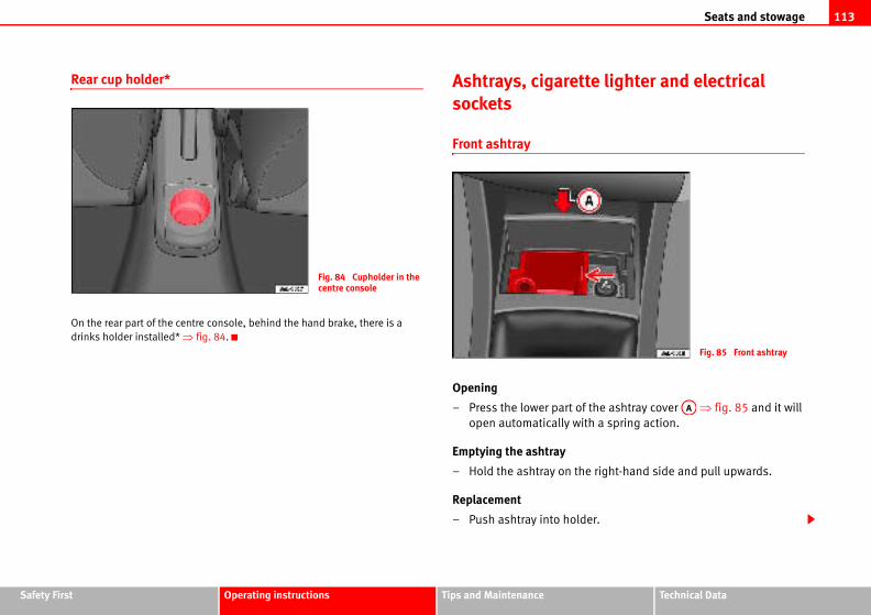
Seats and stowage 113
Safety Fir Technical Data
te lighter and electrical
the ashtray cover ⇒ fig. 85 and it will
th a spring action.
e right-hand side and pull upwards.
er.
Fig. 85 Front ashtray
AA
st Operating instructions Tips and Maintenance
Rear cup holder*
On the rear part of the centre console, behind the hand brake, there is a
drinks holder installed* ⇒ fig. 84.
Ashtrays, cigaretsockets
Front ashtray
Opening
– Press the lower part of
open automatically wi
Emptying the ashtray
– Hold the ashtray on th
Replacement
– Push ashtray into hold
Fig. 84 Cupholder in the centre console
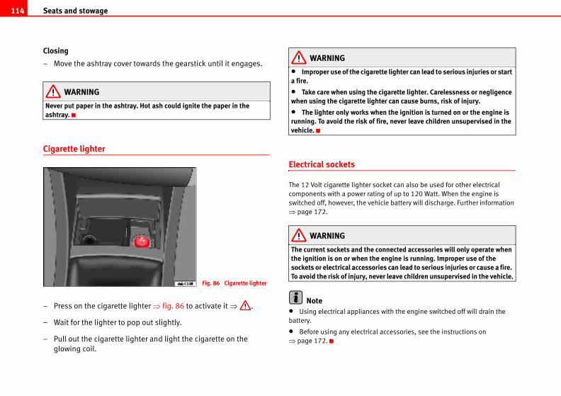
Seats and stowage114
tte lighter can lead to serious injuries or start
cigarette lighter. Carelessness or negligence ter can cause burns, risk of injury.
en the ignition is turned on or the engine is fire, never leave children unsupervised in the
cket can also be used for other electrical
ng of up to 120 Watt. When the engine is
icle battery will discharge. Further information
onnected accessories will only operate when engine is running. Improper use of the ies can lead to serious injuries or cause a fire.
ver leave children unsupervised in the vehicle.
s with the engine switched off will drain the
l accessories, see the instructions on
Closing
– Move the ashtray cover towards the gearstick until it engages.
WARNING
Never put paper in the ashtray. Hot ash could ignite the paper in the ashtray.
Cigarette lighter
– Press on the cigarette lighter ⇒ fig. 86 to activate it ⇒ .
– Wait for the lighter to pop out slightly.
– Pull out the cigarette lighter and light the cigarette on the
glowing coil.
WARNING
• Improper use of the cigarea fire.
• Take care when using thewhen using the cigarette ligh
• The lighter only works whrunning. To avoid the risk of vehicle.
Electrical sockets
The 12 Volt cigarette lighter so
components with a power rati
switched off, however, the veh
⇒ page 172.
WARNING
The current sockets and the cthe ignition is on or when thesockets or electrical accessorTo avoid the risk of injury, ne
Note• Using electrical appliance
battery.
• Before using any electrica
⇒ page 172.
Fig. 86 Cigarette lighter
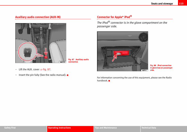
Seats and stowage 115
Safety Fir Technical Data
od®
in the glove compartment on the
e use of this equipment, please see the Radio
Fig. 88 iPod connection in glove box on passenger side.
st Operating instructions Tips and Maintenance
Auxiliary audio connection (AUX-IN)
– Lift the AUX. cover ⇒ fig. 87.
– Insert the pin fully (See the radio manual).
Connector for Apple* iP
The iPod® connector is
passenger side.
For information concerning th
handbook.
Fig. 87 Auxiliary audio connection
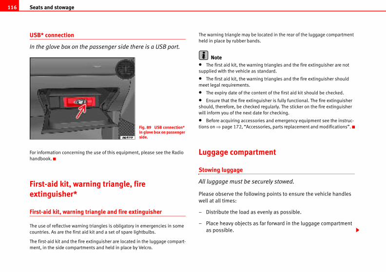
Seats and stowage116
ocated in the rear of the luggage compartment
.
g triangles and the fire extinguisher are not
tandard.
g triangles and the fire extinguisher should
tent of the first aid kit should be checked.
uisher is fully functional. The fire extinguisher
regularly. The sticker on the fire extinguisher
e for checking.
ies and emergency equipment see the instruc-
ories, parts replacement and modifications”.
ent
urely stowed.
ng points to ensure the vehicle handles
venly as possible.
far forward in the luggage compartment
USB* connection
In the glove box on the passenger side there is a USB port.
For information concerning the use of this equipment, please see the Radio
handbook.
First-aid kit, warning triangle, fire extinguisher*
First-aid kit, warning triangle and fire extinguisher
The use of reflective warning triangles is obligatory in emergencies in some
countries. As are the first aid kit and a set of spare lightbulbs.
The first-aid kit and the fire extinguisher are located in the luggage compart-
ment, in the side compartments and held in place by Velcro.
The warning triangle may be l
held in place by rubber bands
Note• The first aid kit, the warnin
supplied with the vehicle as s
• The first aid kit, the warnin
meet legal requirements.
• The expiry date of the con
• Ensure that the fire exting
should, therefore, be checked
will inform you of the next dat
• Before acquiring accessor
tions on ⇒ page 172, “Access
Luggage compartm
Stowing luggage
All luggage must be sec
Please observe the followi
well at all times:
– Distribute the load as e
– Place heavy objects as
as possible.
Fig. 89 USB connection* in glove box on passenger side.
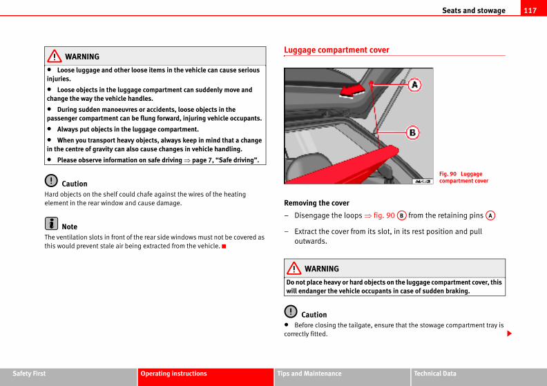
Seats and stowage 117
Safety Fir Technical Data
cover
fig. 90 from the retaining pins
its slot, in its rest position and pull
bjects on the luggage compartment cover, this cupants in case of sudden braking.
e, ensure that the stowage compartment tray is
Fig. 90 Luggage compartment cover
AB AA
st Operating instructions Tips and Maintenance
WARNING
• Loose luggage and other loose items in the vehicle can cause serious injuries.
• Loose objects in the luggage compartment can suddenly move and change the way the vehicle handles.
• During sudden manoeuvres or accidents, loose objects in the passenger compartment can be flung forward, injuring vehicle occupants.
• Always put objects in the luggage compartment.
• When you transport heavy objects, always keep in mind that a change in the centre of gravity can also cause changes in vehicle handling.
• Please observe information on safe driving ⇒ page 7, “Safe driving”.
CautionHard objects on the shelf could chafe against the wires of the heating
element in the rear window and cause damage.
NoteThe ventilation slots in front of the rear side windows must not be covered as
this would prevent stale air being extracted from the vehicle.
Luggage compartment
Removing the cover
– Disengage the loops ⇒
– Extract the cover from
outwards.
WARNING
Do not place heavy or hard owill endanger the vehicle oc
Caution• Before closing the tailgat
correctly fitted.
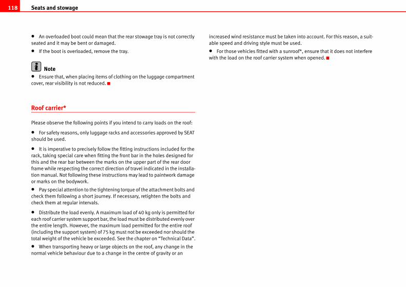
Seats and stowage118
st be taken into account. For this reason, a suit-
ust be used.
ith a sunroof*, ensure that it does not interfere
er system when opened.
• An overloaded boot could mean that the rear stowage tray is not correctly
seated and it may be bent or damaged.
• If the boot is overloaded, remove the tray.
Note• Ensure that, when placing items of clothing on the luggage compartment
cover, rear visibility is not reduced.
Roof carrier*
Please observe the following points if you intend to carry loads on the roof:
• For safety reasons, only luggage racks and accessories approved by SEAT
should be used.
• It is imperative to precisely follow the fitting instructions included for the
rack, taking special care when fitting the front bar in the holes designed for
this and the rear bar between the marks on the upper part of the rear door
frame while respecting the correct direction of travel indicated in the installa-
tion manual. Not following these instructions may lead to paintwork damage
or marks on the bodywork.
• Pay special attention to the tightening torque of the attachment bolts and
check them following a short journey. If necessary, retighten the bolts and
check them at regular intervals.
• Distribute the load evenly. A maximum load of 40 kg only is permitted for
each roof carrier system support bar, the load must be distributed evenly over
the entire length. However, the maximum load permitted for the entire roof
(including the support system) of 75 kg must not be exceeded nor should the
total weight of the vehicle be exceeded. See the chapter on “Technical Data”.
• When transporting heavy or large objects on the roof, any change in the
normal vehicle behaviour due to a change in the centre of gravity or an
increased wind resistance mu
able speed and driving style m
• For those vehicles fitted w
with the load on the roof carri
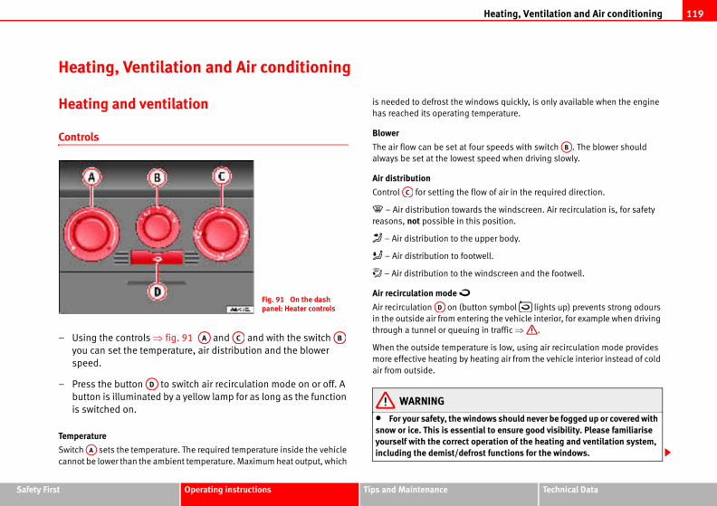
Heating, Ventilation and Air conditioning 119
Safety Fir Technical Data
ows quickly, is only available when the engine
perature.
r speeds with switch . The blower should
peed when driving slowly.
w of air in the required direction.
the windscreen. Air recirculation is, for safety
position.
per body.
ell.
indscreen and the footwell.
n symbol lights up) prevents strong odours
g the vehicle interior, for example when driving
in traffic ⇒ .
re is low, using air recirculation mode provides
ting air from the vehicle interior instead of cold
ows should never be fogged up or covered with l to ensure good visibility. Please familiarise
eration of the heating and ventilation system, t functions for the windows.
AB
st Operating instructions Tips and Maintenance
Heating, Ventilation and Air conditioning
Heating and ventilation
Controls
– Using the controls ⇒ fig. 91 and and with the switch
you can set the temperature, air distribution and the blower
speed.
– Press the button to switch air recirculation mode on or off. A
button is illuminated by a yellow lamp for as long as the function
is switched on.
Temperature
Switch sets the temperature. The required temperature inside the vehicle
cannot be lower than the ambient temperature. Maximum heat output, which
is needed to defrost the wind
has reached its operating tem
Blower
The air flow can be set at fou
always be set at the lowest s
Air distribution
Control for setting the flo
– Air distribution towards
reasons, not possible in this
– Air distribution to the up
– Air distribution to footw
– Air distribution to the w
Air recirculation mode
Air recirculation on (butto
in the outside air from enterin
through a tunnel or queuing
When the outside temperatu
more effective heating by hea
air from outside.
WARNING
• For your safety, the windsnow or ice. This is essentiayourself with the correct opincluding the demist/defros
Fig. 91 On the dash panel: Heater controls
AA AC AB
AD
AA
AC
AD
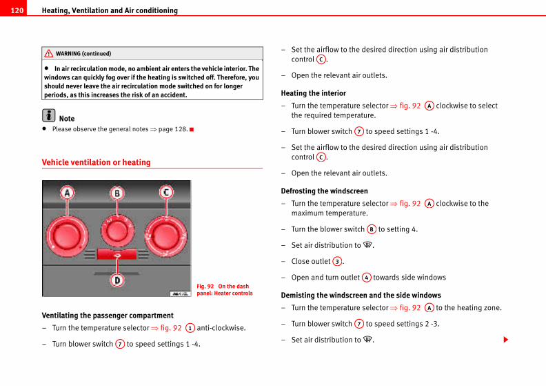
Heating, Ventilation and Air conditioning120
esired direction using air distribution
utlets.
lector ⇒ fig. 92 clockwise to select
re.
to speed settings 1 -4.
esired direction using air distribution
utlets.
lector ⇒ fig. 92 clockwise to the
.
to setting 4.
.
towards side windows
and the side windows
lector ⇒ fig. 92 to the heating zone.
to speed settings 2 -3.
.
AA
AA
AB
AA
• In air recirculation mode, no ambient air enters the vehicle interior. The windows can quickly fog over if the heating is switched off. Therefore, you should never leave the air recirculation mode switched on for longer periods, as this increases the risk of an accident.
Note• Please observe the general notes ⇒ page 128.
Vehicle ventilation or heating
Ventilating the passenger compartment
– Turn the temperature selector ⇒ fig. 92 anti-clockwise.
– Turn blower switch to speed settings 1 -4.
– Set the airflow to the d
control .
– Open the relevant air o
Heating the interior
– Turn the temperature se
the required temperatu
– Turn blower switch
– Set the airflow to the d
control .
– Open the relevant air o
Defrosting the windscreen
– Turn the temperature se
maximum temperature
– Turn the blower switch
– Set air distribution to
– Close outlet .
– Open and turn outlet
Demisting the windscreen
– Turn the temperature se
– Turn blower switch
– Set air distribution to
WARNING (continued)
Fig. 92 On the dash panel: Heater controls
A1
A7
AC
A7
AC
A3
A4
A7
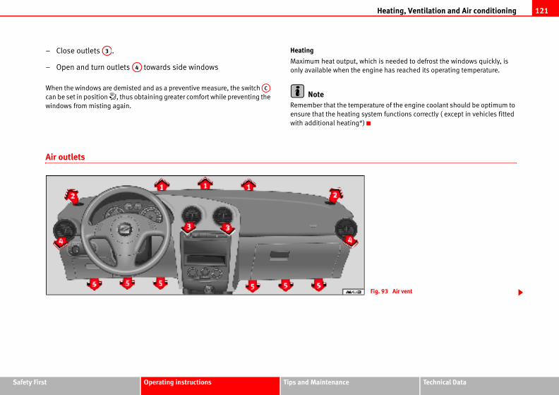
Heating, Ventilation and Air conditioning 121
Safety Fir Technical Data
is needed to defrost the windows quickly, is
ne has reached its operating temperature.
ure of the engine coolant should be optimum to
m functions correctly ( except in vehicles fitted
g. 93 Air vent
st Operating instructions Tips and Maintenance
– Close outlets .
– Open and turn outlets towards side windows
When the windows are demisted and as a preventive measure, the switch
can be set in position , thus obtaining greater comfort while preventing the
windows from misting again.
Heating
Maximum heat output, which
only available when the engi
NoteRemember that the temperat
ensure that the heating syste
with additional heating*)
Air outlets
A3
A4
AC
Fi
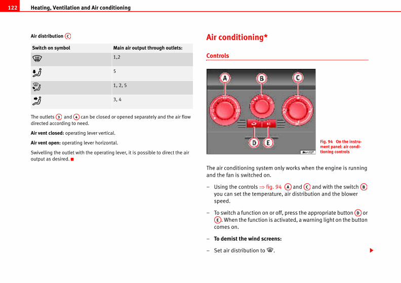
Heating, Ventilation and Air conditioning122
only works when the engine is running
.
g. 94 and and with the switch
ature, air distribution and the blower
or off, press the appropriate button or
is activated, a warning light on the button
ens:
.
Fig. 94 On the instru-ment panel: air condi-tioning controls
AA AC AB
AD
Air distribution
The outlets and can be closed or opened separately and the air flow
directed according to need.
Air vent closed: operating lever vertical.
Air vent open: operating lever horizontal.
Swivelling the outlet with the operating lever, it is possible to direct the air
output as desired.
Air conditioning*
Controls
The air conditioning system
and the fan is switched on
– Using the controls ⇒ fi
you can set the temper
speed.
– To switch a function on
. When the function
comes on.
– To demist the wind scre
– Set air distribution to
Switch on symbol Main air output through outlets:
1,2
5
1, 2, 5
3, 4
AC
A3 A4
AE
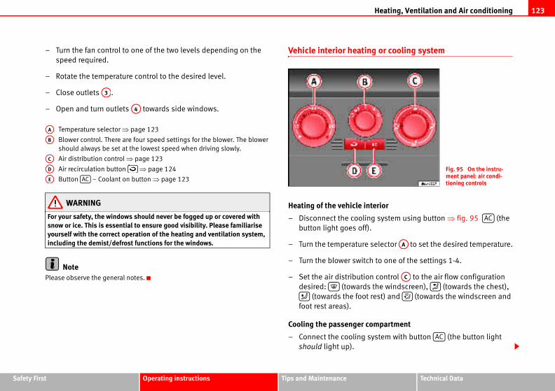
Heating, Ventilation and Air conditioning 123
Safety Fir Technical Data
or cooling system
erior
system using button ⇒ fig. 95 (the
elector to set the desired temperature.
to one of the settings 1-4.
control to the air flow configuration
the windscreen), (towards the chest),
est) and (towards the windscreen and
mpartment
stem with button (the button light
Fig. 95 On the instru-ment panel: air condi-tioning controls
AC
AA
AC
AC
st Operating instructions Tips and Maintenance
– Turn the fan control to one of the two levels depending on the
speed required.
– Rotate the temperature control to the desired level.
– Close outlets .
– Open and turn outlets towards side windows.
Temperature selector ⇒ page 123
Blower control. There are four speed settings for the blower. The blower
should always be set at the lowest speed when driving slowly.
Air distribution control ⇒ page 123
Air recirculation button ⇒ page 124
Button – Coolant on button ⇒ page 123
WARNING
For your safety, the windows should never be fogged up or covered with snow or ice. This is essential to ensure good visibility. Please familiarise yourself with the correct operation of the heating and ventilation system, including the demist/defrost functions for the windows.
NotePlease observe the general notes.
Vehicle interior heating
Heating of the vehicle int
– Disconnect the cooling
button light goes off).
– Turn the temperature s
– Turn the blower switch
– Set the air distribution
desired: (towards
(towards the foot r
foot rest areas).
Cooling the passenger co
– Connect the cooling sy
should light up).
A3
A4
AA
AB
AC
AD
AE AC
Heating, Ventilation and Air conditioning124
revents fumes or unpleasant smells
e.
switched on (button ⇒ page 123, fig. 95
ours in the outside air do not enter the vehicle
sing through a tunnel or in queuing traffic.
e is low, using air recirculation mode provides
ting air from the vehicle interior instead of cold
is high, using air recirculation mode provides
ing air from the vehicle interior instead of warm
ulation is not possible when the control for air
screen setting .
ambient air enters the vehicle interior. If the itched off, the windows can quickly mist over. leave the air recirculation mode switched on creases the risk of an accident.
ged the air recirculation connects automatically
aust fumes in the vehicle on travelling back-
button does not light up.
s turned to the coldest setting (blue point) and
e “Air recirculation” function is automatically
assenger compartment rapidly using a
nction indicator will light.
– Turn the temperature control switch until the desired interior
temperature is obtained.
– Turn the blower switch to one of the settings 1-4.
– Set the air distribution control to the air flow configuration
desired: (towards the windscreen), (towards the chest),
(towards the foot rest) and (towards the windscreen and
foot rest areas).
Heating
Maximum heat output, which is needed to defrost the windows quickly, is
only available when the engine has reached its operating temperature.
Coolant system
When the cooling system is switched on, not only the temperature, but also
the air humidity in the vehicle interior is reduced. This improves comfort for
the vehicle occupants and prevents misting of the windows when the outside
air humidity is high.
If the cooling system cannot be switched on this may be due to the following
reasons:
• the engine is not running.
• The blower is switched off.
• The outside temperature is lower than +5°C.
• the cooling system compressor has been temporarily switched off
because the engine coolant temperature is too high.
• The air conditioning fuse is faulty.
• Another fault in the vehicle. Have the air conditioning checked by a qual-
ified workshop.
Air recirculation
Air recirculation mode p
from entering the vehicl
When air recirculation mode is
with warning lamp) strong od
interior, for example when pas
When the outside temperatur
more effective heating by hea
air from outside.
When the outside temperature
more effective cooling by cool
air from outside.
For reasons of safety, air recirc
distribution is set to the wind
WARNING
In air recirculation mode, no air conditioning system is swTherefore, you should never for longer periods, as this in
Note• When reverse gear is enga
to prevent the entrance of exh
wards. The control light on the
• If the temperature control i
the switch is activated, th
activated in order to cool the p
minimum of energy and the fu
AC
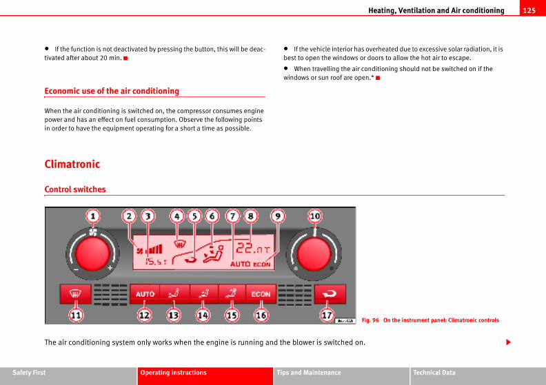
Heating, Ventilation and Air conditioning 125
Safety Fir Technical Data
verheated due to excessive solar radiation, it is
doors to allow the hot air to escape.
nditioning should not be switched on if the
.*
g. 96 On the instrument panel: Climatronic controls
st Operating instructions Tips and Maintenance
• If the function is not deactivated by pressing the button, this will be deac-
tivated after about 20 min.
Economic use of the air conditioning
When the air conditioning is switched on, the compressor consumes engine
power and has an effect on fuel consumption. Observe the following points
in order to have the equipment operating for a short a time as possible.
• If the vehicle interior has o
best to open the windows or
• When travelling the air co
windows or sun roof are open
Climatronic
Control switches
The air conditioning system only works when the engine is running and the blower is switched on.
Fi
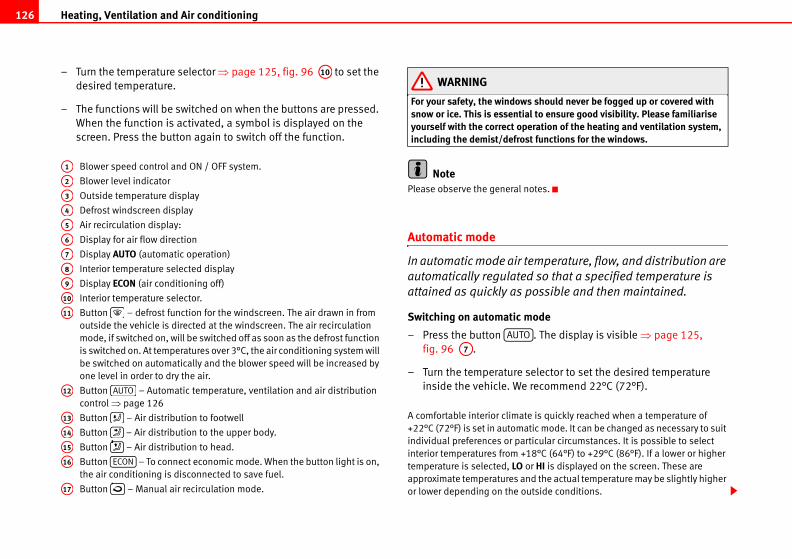
Heating, Ventilation and Air conditioning126
should never be fogged up or covered with to ensure good visibility. Please familiarise ration of the heating and ventilation system, functions for the windows.
tes.
mperature, flow, and distribution are
so that a specified temperature is
ossible and then maintained.
ode
. The display is visible ⇒ page 125,
lector to set the desired temperature
ecommend 22°C (72°F).
is quickly reached when a temperature of
ic mode. It can be changed as necessary to suit
icular circumstances. It is possible to select
8°C (64°F) to +29°C (86°F). If a lower or higher
HI is displayed on the screen. These are
d the actual temperature may be slightly higher
tside conditions.
– Turn the temperature selector ⇒ page 125, fig. 96 to set the
desired temperature.
– The functions will be switched on when the buttons are pressed.
When the function is activated, a symbol is displayed on the
screen. Press the button again to switch off the function.
Blower speed control and ON / OFF system.
Blower level indicator
Outside temperature display
Defrost windscreen display
Air recirculation display:
Display for air flow direction
Display AUTO (automatic operation)
Interior temperature selected display
Display ECON (air conditioning off)
Interior temperature selector.
Button – defrost function for the windscreen. The air drawn in from
outside the vehicle is directed at the windscreen. The air recirculation
mode, if switched on, will be switched off as soon as the defrost function
is switched on. At temperatures over 3°C, the air conditioning system will
be switched on automatically and the blower speed will be increased by
one level in order to dry the air.
Button – Automatic temperature, ventilation and air distribution
control ⇒ page 126
Button – Air distribution to footwell
Button – Air distribution to the upper body.
Button – Air distribution to head.
Button – To connect economic mode. When the button light is on,
the air conditioning is disconnected to save fuel.
Button – Manual air recirculation mode.
WARNING
For your safety, the windowssnow or ice. This is essentialyourself with the correct opeincluding the demist/defrost
NotePlease observe the general no
Automatic mode
In automatic mode air te
automatically regulated
attained as quickly as p
Switching on automatic m
– Press the button
fig. 96 .
– Turn the temperature se
inside the vehicle. We r
A comfortable interior climate
+22°C (72°F) is set in automat
individual preferences or part
interior temperatures from +1
temperature is selected, LO or
approximate temperatures an
or lower depending on the ou
A10
A1
A2
A3
A4
A5
A6
A7
A8
A9
A10
A11
A12 AUTO
A13
A14
A15
A16 ECON
A17
AUTO
A7
Heating, Ventilation and Air conditioning 127
Safety Fir Technical Data
djusted with the blower control . Always have
etting to ensure a constant flow of fresh air into
witched off (no level displayed ) and the
e left, the Climatronic is switched off. Then OFF
d using the buttons , and . It is also
ome of the air outlets separately.
g system on and off
itches off the air cooling system to save fuel.
be regulated. The set temperature can then
than the outside temperature.
prevents fumes or unpleasant smells
le.
switch air recirculation mode on or off.
l ⇒ page 125, fig. 96 is displayed
ts strong odours in the ambient air from
or example when passing through a tunnel or in
re is low, using air recirculation mode provides
ting air from the vehicle interior instead of cold
A1
A2
A5
st Operating instructions Tips and Maintenance
Climatronic maintains a constant temperature level fully automatically. The
temperature of the air supplied to the interior, the blower speed and the air
distribution are regulated automatically. The system also allows for the effect
of strong sunlight, so there is no need for manual adjustment. Therefore,
automatic mode provides the best comfort for the vehicle occupants in virtu-
ally all conditions throughout the year.
Automatic mode is switched off whenever an adjustment is made using the
buttons for the air distribution, blower or . The temperature continues
to be regulated.
Manual mode
In manual mode you can adjust the air temperature, flow, and
distribution yourself.
Switching on manual mode
– Press one of the buttons ⇒ page 125, fig. 96 to , or turn
the blower control . The display is switched off .
Temperature
It is possible to select interior temperatures from +18°C (64°F) to +29°C
(86°F). These are approximate temperatures and the actual temperature may
be slightly higher or lower depending on the outside conditions.
If a temperature below 18°C (64°F) is selected, the display switches to LO. In
this setting the system runs at maximum cooling output and the temperature
is not regulated.
If a temperature above 29°C (86°F) is selected the display indicates HI. In this
setting the system runs at maximum heating output and the temperature is
not controlled.
Blower
The blower can be infinitely a
the blower running at a low s
the vehicle. If the blower is s
control is turned further to th
is displayed on the screen.
Air distribution
The air distribution is adjuste
possible to open and close s
Switching the air conditionin
Pressing the button sw
The temperature continues to
only be reached if it is higher
Air recirculation mode
Air recirculation mode
from entering the vehic
– Press the button to
This is ON if the symbo
on the screen.
Air recirculation mode preven
entering the vehicle interior, f
queuing traffic.
When the outside temperatu
more effective heating by hea
air from outside.
ECON
A13 A15
A1 A7
ECON
Heating, Ventilation and Air conditioning128
conditioning is damaged, switch off the air
to prevent further damage and have it
op.
ning system require specialist knowledge and
commend that you take the vehicle to a quali-
s occur.
rature outside the vehicle are high, condensa-r in the cooling system and form a pool under-
letely normal and there is no need to suspect
front of the windscreen free of snow, ice and
cooling is not impaired, and to prevent the
s through the passenger compartment and is
r this purpose. Do not cover these slots with
jects.
m operates most effectively with the windows
osed. However, if the sun has heated up the
ooled more quickly by opening the windows for
irculation mode is on, as smoke drawn into the
s a residue on the evaporator, producing a
es the compressor switches off automatically.
witched on either.
he air conditioning at least once a month, to
nd prevent leaks. If a decrease in the cooling
rised Service Centre should be consulted to
N
When the outside temperature is high, using air recirculation mode provides
more effective cooling by cooling air from the vehicle interior instead of warm
air from outside.
For reasons of safety, air recirculation is not possible when the control for air
distribution is set to the windscreen setting .
WARNING
In air recirculation mode, no ambient air enters the vehicle interior. If the air conditioning system is switched off, the windows can quickly mist over. Therefore, you should never leave the air recirculation mode switched on for longer periods, as this increases the risk of an accident.
NoteWhen reverse gear is engaged the air recirculation connects automatically to
prevent the entrance of exhaust fumes in the vehicle on travelling backwards.
In this case the symbol for air recirculation is not displayed.
General notes
The pollen filter
The pollution filter (a combined particulate filter and active carbon filter)
serves as a barrier against impurities in the ambient air, including dust and
pollen.
For the air conditioning system to work with maximum efficiency, the pollen
filter must be replaced at the intervals specified in the Maintenance Program.
If the filter loses efficiency prematurely due to use in areas with very high
levels of air pollution, the pollen filter must be changed more frequently than
stated in the Service Schedule.
Caution• If you suspect that the air
conditioning with button
checked by a qualified worksh
• Repairs to the air conditio
special tools. Therefore, we re
fied workshop should problem
Note• If the humidity and tempe
tion can drip off the evaporato
neath the vehicle, this is comp
a leak.
• Keep the air intake slots in
leaves to ensure heating and
windows misting over.
• The air from the vents flow
extracted by slots designed fo
articles of clothing or other ob
• The air conditioning syste
and the sliding/tilting roof* cl
vehicle, the air inside can be c
a short period.
• Do not smoke while air rec
air conditioning system leave
permanent unpleasant odour.
• At low outside temperatur
The button cannot be s
• It is advisable to connect t
lubricate the system gaskets a
capacity is detected, an Autho
check the system.
ECO
AUTO
Heating, Ventilation and Air conditioning 129
Safety Fir Technical Data
st Operating instructions Tips and Maintenance• For correct operation of the system, do not block the grille between the
button and the button .
• When the engine is under extreme strain, switch off the compressor for a
moment.
AUTO
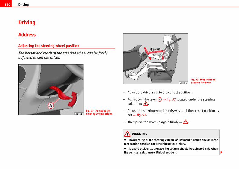
Driving130
the correct position.
⇒ fig. 97 located under the steering
el in this way until the correct position is
again firmly ⇒ .
ing column adjustment function and an incor-ult in serious injury.
eering column should be adjusted only when k of accident.
Fig. 98 Proper sitting position for driver
Driving
Address
Adjusting the steering wheel position
The height and reach of the steering wheel can be freely
adjusted to suit the driver.
– Adjust the driver seat to
– Push down the lever
column ⇒ .
– Adjust the steering whe
set ⇒ fig. 98.
– Then push the lever up
WARNING
• Incorrect use of the steerrect seating position can res
• To avoid accidents, the stthe vehicle is stationary. Ris
Fig. 97 Adjusting the steering wheel position
AA
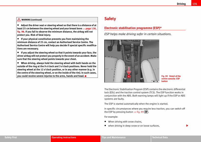
Driving 131
Safety Fir Technical Data
programme (ESP)*
safer in certain situations.
rogram (ESP) contains the electronic differential
ntrol system (TCS). The ESP function works in
th warning lamps will light up if the ESP or ABS
ally when the engine is started.
ere you require less traction, you can switch off
fig. 99 .
hains,
w or on loose surfaces,
Fig. 99 Detail of the centre console: ESP button
st Operating instructions Tips and Maintenance
• Adjust the driver seat or steering wheel so that there is a distance of at least 25 cm between the steering wheel and your breast bone ⇒ page 130, fig. 98. If you fail to observe the minimum distance, the airbag will not protect you. Risk of fatal injury.
• If your physical constitution prevents you from maintaining the minimum distance of 25 cm, contact an Authorised Service Centre. The Authorised Service Centre will help you decide if special specific modifica-tions are necessary.
• If you adjust the steering wheel so that it points towards your face, the driver airbag will not protect you properly in the event of an accident. Make sure that the steering wheel points towards your chest.
• When driving, always hold the steering wheel with both hands on the outside of the ring at the 9 o'clock and 3 o'clock positions. Never hold the steering wheel at the 12 o'clock position, or in any other manner (e.g. in the centre of the steering wheel, or on the inside of the rim). In such cases, you could receive severe injuries to the arms, hands and head.
Safety
Electronic stabilisation
ESP helps make driving
The Electronic Stabilisation P
lock (EDL) and the traction co
conjunction with the ABS. Bo
systems are faulty.
The ESP is started automatic
In specific circumstances wh
the ESP by pressing button ⇒
For example:
• When driving with snow c
• when driving in deep sno
WARNING (continued)
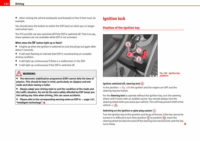
Driving132
key
lock
ignition and the engine are OFF and the
te without the ignition key, turn the steering
dible sound. You should always lock the
your vehicle. This will help prevent theft of the
low plug system
sition and let go of the key. If the key cannot be
m position to position , move the
d off the steering lock mechanism) until the key
Fig. 100 Ignition key positions
A0
A1
A0 A12
• when rocking the vehicle backwards and forwards to free it from mud, for
example.
You should press the button to switch the ESP back on when you no longer
need wheel spin.
The TCS and EDL are also switched off if the ESP is switched off. That is to say,
these systems are not available while ESP is not activated.
When does the button light up or flash?
• It lights up when the ignition is switched on and should go out again after
about 2 seconds.
• It will start flashing to indicate that ESP is counteracting an unstable
driving condition.
• It will light up continuously if there is a malfunction in the ESP.
• It will light up continuously if the ESP is switched off.
WARNING
• The electronic stabilisation programme (ESP) cannot defy the laws of physics. This should be kept in mind, particularly on slippery and wet roads and when towing a trailer.
• Always adapt your driving style to suit the condition of the roads and the traffic situation. Do not let the extra safety afforded by ESP tempt you into taking any risks when driving, this can cause accidents.
• Please refer to the corresponding warning notes on ESP in ⇒ page 147, “Intelligent technology”.
Ignition lock
Position of the ignition
Ignition switched off, steering
In the position ⇒ fig. 100 the
steering may be locked.
For the Steering lock to opera
wheel until it locks with an au
steering wheel when you leave
vehicle ⇒ .
Switching on the ignition or g
Turn the ignition key to this po
turned or is difficult to turn fro
steering wheel (to take the loa
turns freely.
Driving 133
Safety Fir Technical Data
ts unauthorised persons from driving
hat deactivates the electronic immobiliser auto-
erted into the ignition.
ted again automatically as soon as you pull the
d using a genuine SEAT key with the correct
ed properly if you do not have a genuine SEAT
ping the engine
started using a genuine SEAT key with
the neutral position and depress the
old it in this position, the starter will then
ngine.
position ⇒ page 132 to start the engine.
st Operating instructions Tips and Maintenance
Starting
The engine is started when the key is in this position. Electrical components
with a high power consumption are switched off temporarily.
Each time that the vehicle must be started, the ignition key must be turned to
the position . The repetitive start prevention lock of the ignition prevents
possible damage to the starter motor if the engine is already running.
WARNING
• Wait for the vehicle to come to a standstill before removing the ignition key from the lock. The steering lock could be activated immediately - Risk of accident!
• Always remove the key from the ignition lock when leaving the vehicle, even if you only intend to be gone for a short period. This is especially important if you must leave children or disabled people in the vehicle, they could accidentally start the engine or work electrical equipment such as the windows possibly resulting in an accident.
• Unsupervised use of the keys could result in the engine being started or electrical systems, such as the electric windows, being used. This can result in serious injury.
CautionThe starter motor will only work when the engine is stopped (ignition key
position ).
Electronic immobiliser
The immobiliser preven
the vehicle.
Inside the key there is a chip t
matically when the key is ins
The immobiliser will be activa
key out of the ignition lock.
The engine can only be starte
code.
NoteThe vehicle cannot be operat
key.
Starting and stop
Starting petrol engines
The engine can only be
the correct code.
– Move the gear lever to
clutch pedal fully and h
only have to turn the e
– Turn the ignition key to
A2
A0
A2
Driving134
vironment running the engine with the vehicle stationary.
s you start the engine. This helps the engine
aster and reduces emissions.
tarted using a genuine SEAT key with
the neutral position and depress the
old it in this position, the starter will then
gine.
the starting position.
position ⇒ page 132, fig. 100 . The
light for engine pre-heating.
goes out, turn the key to position to
t press the accelerator.
y as soon as the engine starts, the starter
wed to run on with the engine.
ngine may be a little noisy for the first few
built up in the hydraulic valve compensators.
ause for concern.
the engine, see ⇒ page 230.
A1
A2
– Let go of the ignition key as soon as the engine starts; the starter
motor must not be allowed to run on with the engine.
After starting a very hot engine, you may need to press the accelerator briefly.
When starting from cold, the engine may be a little noisy for the first few
seconds until oil pressure has built up in the hydraulic valve compensators.
This is quite normal, and no cause for concern.
If the engine does not start immediately, switch off the starter after about
10 seconds and try again after about half a minute. If the engine still does not
start, the fuel pump fuse should be checked ⇒ page 213, “Fuses”.
WARNING
• Never start or run the engine in unventilated or closed rooms. The exhaust fumes contain carbon monoxide, an odourless and colourless poisonous gas. Risk of fatal accidents. Carbon monoxide can cause loss of consciousness. It can also cause death.
• Never leave the vehicle unattended if the engine is running.
• Never use “cold start sprays”, they could explode or cause the engine to run at high revs. Risk of injury.
Caution• When the engine is cold, you should avoid high engine speeds, driving at
full throttle and over-loading the engine. Risk of engine damage.
• The vehicle should not be pushed or towed for more than approximately
50 metres to start the engine. Fuel could enter the catalytic converter and
damage it.
• Before attempting to push-start or tow a vehicle to start it, you should first
try to start it using the battery of another vehicle. Note and follow the instruc-
tions ⇒ page 230, “Jump-starting”.
For the sake of the enDo not warm-up the engine by
You should drive off as soon a
reach operating temperature f
Starting diesel engines
The engine can only be s
the correct code.
– Move the gear lever to
clutch pedal fully and h
only have to turn the en
– Turn the ignition key to
– Turn the ignition key to
indication lamp will
– When the warning lamp
start the engine. Do no
– Let go of the ignition ke
motor must not be allo
When starting from cold, the e
seconds until oil pressure has
This is quite normal, and no c
If there are problems starting
Driving 135
Safety Fir Technical Data
nvironmenty running the engine with the vehicle stationary.
as you start the engine. This helps the engine
faster and reduces emissions.
e
position ⇒ page 132, fig. 100 .
ff the radiator fan may run on for up to 10
s switched off. It is also possible that it will turn
perature of the coolant increases due to the
the engine compartment or if this is heated due
heat of the sun.
ine until the vehicle is stationary.
nly when the engine is running. You will need ehicle when the engine is switched off. As you anner, there is a greater risk of accidents and
gage immediately when the key is removed ehicle cannot be steered. Risk of accident.
A0
st Operating instructions Tips and Maintenance
Glow plug system for the diesel engine
To avoid unnecessary load on the battery, do not use any other major elec-
trical equipment while the glow plugs are pre-heating.
Start the engine as soon as the glow plug warning lamp ⇒ page 63 goes out.
Starting the engine after the fuel tank has been completely run dry
If the fuel tank has been completely run dry, it may take longer than normal
(up to one minute) to start the engine after refuelling with diesel fuel. This is
because the system must eliminate air first.
WARNING
• Never start or run the engine in unventilated or closed rooms. The exhaust fumes contain carbon monoxide, an odourless and colourless poisonous gas. Risk of fatal accidents. Carbon monoxide can cause loss of consciousness. It can also cause death.
• Never leave the vehicle unattended if the engine is running.
• Never use “cold start sprays”, they could explode or cause the engine to run at high revs. Risk of injury.
Caution• When the engine is cold, you should avoid high engine speeds, driving at
full throttle and over-loading the engine. Risk of engine damage.
• The vehicle should not be pushed or towed for more than approximately
50 metres to start the engine. Fuel could enter the catalytic converter and
damage it.
• Before attempting to push-start or tow a vehicle to start it, you should first
try to start it using the battery of another vehicle. Note and follow the instruc-
tions ⇒ page 230, “Jump-starting”.
For the sake of the eDo not warm-up the engine b
You should drive off as soon
reach operating temperature
Switching off the engin
– Stopping the engine.
– Turn the ignition key to
After the engine is switched o
minutes, even if the ignition i
itself on once more if the tem
elimination of built up heat in
to prolonged exposure to the
WARNING
• Never switch off the eng
• The brake servo works omore strength to brake the vcannot brake in the normal mserious injury.
• The steering lock can enfrom the ignition lock. The v
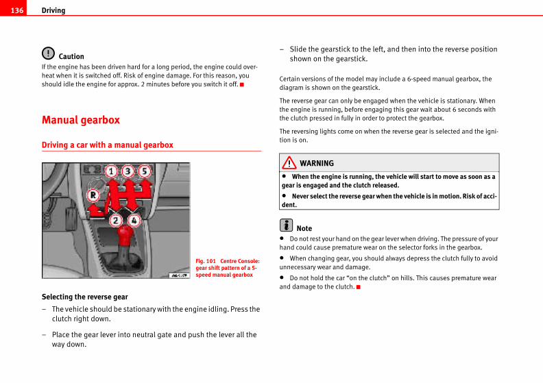
Driving136
e left, and then into the reverse position
.
may include a 6-speed manual gearbox, the
stick.
ngaged when the vehicle is stationary. When
engaging this gear wait about 6 seconds with
rder to protect the gearbox.
when the reverse gear is selected and the igni-
ng, the vehicle will start to move as soon as a ch released.
ear when the vehicle is in motion. Risk of acci-
e gear lever when driving. The pressure of your
ear on the selector forks in the gearbox.
should always depress the clutch fully to avoid
e.
e clutch” on hills. This causes premature wear
CautionIf the engine has been driven hard for a long period, the engine could over-
heat when it is switched off. Risk of engine damage. For this reason, you
should idle the engine for approx. 2 minutes before you switch it off.
Manual gearbox
Driving a car with a manual gearbox
Selecting the reverse gear
– The vehicle should be stationary with the engine idling. Press the
clutch right down.
– Place the gear lever into neutral gate and push the lever all the
way down.
– Slide the gearstick to th
shown on the gearstick
Certain versions of the model
diagram is shown on the gear
The reverse gear can only be e
the engine is running, before
the clutch pressed in fully in o
The reversing lights come on
tion is on.
WARNING
• When the engine is runnigear is engaged and the clut
• Never select the reverse gdent.
Note• Do not rest your hand on th
hand could cause premature w
• When changing gear, you
unnecessary wear and damag
• Do not hold the car “on th
and damage to the clutch.
Fig. 101 Centre Console: gear shift pattern of a 5-speed manual gearbox
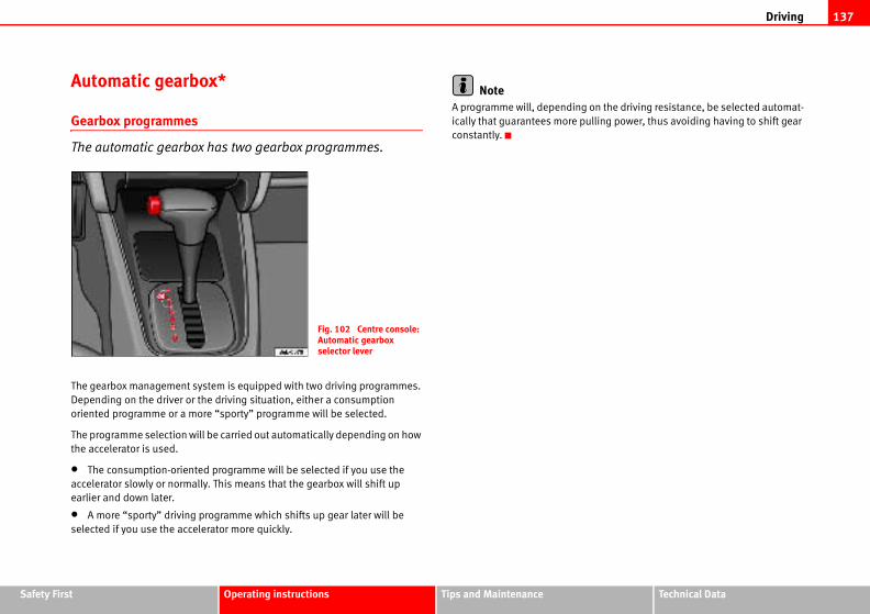
Driving 137
Safety Fir Technical Data
on the driving resistance, be selected automat-
ulling power, thus avoiding having to shift gear
st Operating instructions Tips and Maintenance
Automatic gearbox*
Gearbox programmes
The automatic gearbox has two gearbox programmes.
The gearbox management system is equipped with two driving programmes.
Depending on the driver or the driving situation, either a consumption
oriented programme or a more “sporty” programme will be selected.
The programme selection will be carried out automatically depending on how
the accelerator is used.
• The consumption-oriented programme will be selected if you use the
accelerator slowly or normally. This means that the gearbox will shift up
earlier and down later.
• A more “sporty” driving programme which shifts up gear later will be
selected if you use the accelerator more quickly.
NoteA programme will, depending
ically that guarantees more p
constantly.
Fig. 102 Centre console: Automatic gearbox selector lever
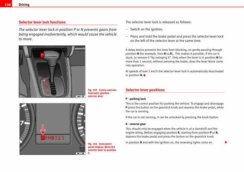
Driving138
leased as follows:
e pedal and press the selector lever lock
or lever at the same time.
ver form blocking, on gently passing through
R to D),. This makes it possible, if the car is
ng it”. Only when the lever is in position N for
ressing the brake, does the lever block come
elector lever lock is automatically deactivated
parking the vehicle. To engage and disengage
stick knob and depress the brake pedal, while
be unlocked by pressing the knob button.
when the vehicle is at a standstill and the
g position R, starting from position P or N,
ress the button on the gearstick knob.
ition on, the reversing lights come on.
Selector lever lock functions
The selector lever lock in position P or N prevents gears from
being engaged inadvertently, which would cause the vehicle
to move.
The selector lever lock is re
– Switch on the ignition.
– Press and hold the brak
on the left of the select
A delay device prevents the le
position N (for example, from
stuck, to remove it “by swingi
more than 1 second, without p
into operation.
At speeds of over 5 km/h the s
in position N.
Selector lever positions
P - parking lock
This is the correct position for
P press the button on the gear
the car is running.
If the car is not running, it can
R - reverse gear
This should only be engaged
engine idling. Before engagin
depress the brake pedal and p
In position R and with the ign
Fig. 103 Centre console: Automatic gearbox selector lever
Fig. 104 Instrument panel display: Move the selector lever to position P.
Driving 139
Safety Fir Technical Data
ced in positions 3, 2 and 1 when the change is
matic gearbox does not change to a lower gear
ns is appropriate.
acceleration. When the accelerator is
d depending on the vehicle speed and engine
aged. As soon as the maximum engine speed
ext gear up is engaged.
eels may skid if the kick-down feature is acti- slippery roads. Danger of skidding!
d when the selector lever is at N or P
l and the engine is running, always depress the
a range.
g a range when the engine is at a standstill
st Operating instructions Tips and Maintenance
N - neutral (idling)
To take the lever out of position N at speeds of below 5 km/h or when the car
is at a standstill but the ignition is switched on, depress the brake pedal and
press the lock button on the gearstick knob.
D - Drive (forwards)
The four gears automatically change up or down, depending on engine load
and vehicle speed.
In certain conditions it is preferable to place the selector lever provisionally in
one of the positions described below:
3 - Position for uneven surfaces
Gears 1st, 2nd and 3rd automatically change up or down depending on the
engine load and vehicle speed. 4th gear is blocked. This increases the engine
braking effect when decelerating.
This position is recommended when in position D and under certain driving
conditions, there are frequent changes between 3rd and 4th.
2 - Position for hilly roads
Position recommended for long slopes.
1st and 2nd gear change automatically depending on engine load and
vehicle speed. 3rd and 4th do not operate.
1 - Position for very steep slopes or manoeuvres
Recommended position for extreme slopes.
The vehicle only travels in 1st gear. 2nd, 3rd and 4th are blocked.
The cruise control* can not be used in position 1.
CautionNever move the selector lever to R or P when driving. This could damage the
gearbox. Risk of accident!
NoteThe selector lever can be pla
made manually, but the auto
until the number of revolutio
Kick-down feature
This system allows maximum
depressed to full throttle, an
speed, the lowest gear is eng
for that gear is reached, the n
WARNING
Remember that the drive whvated when driving on icy or
Instructions for driving
Starting
The engine can only be starte
⇒ page 133.
Selecting a range
When the car is at a standstil
brake pedal before selecting
Do not accelerate on selectin
Driving140
matically engage gears.
ed manually. 3rd gear is only available in posi-
r lever.
ector lever 1st gear and reverse gear are avail-
ired to work more, especially due to the lack of
gearbox oil may overheat. In this case, consult
as soon as possible.
cle must always be held with the foot brake This is because an automatic gearbox still g speed, and the vehicle tends to “creep”.
ndstill and the engine is idling, a range is ccelerate accidentally (for example, when rtment), as the car will start to move immedi-
ng engine, place the selector lever in position
m moving out of control, the handbrake en the vehicle is at a standstill. In addition sition P.
If, while driving, the selector lever accidentally moves to position N, first
release the accelerator pedal and wait until the engine slows to idling before
selecting a forward gear ⇒ .
Starting
Select a range (R, D, 3, 2, 1). Wait until the change has taken place and the
power transmission of the drive wheels has stabilised (slight pressure is
noticeable). Then depress the accelerator.
Stopping
In the case of a temporary stop, for example at a traffic light, it is not neces-
sary to move to position N, it is sufficient to brake using the brake pedal. The
engine should only run at idle speed.
Parking
On slopes, first pull handbrake on firmly and then connect block. This
prevents overloading of the locking mechanism, making the subsequent
deactivation easier ⇒ .
Emergency start
For vehicles fitted with an automatic gearbox the engine can not be started by
towing or pushing the vehicle ⇒ page 233.
If the vehicle battery is flat, a battery from another car can be used to jump-
start the car using a set of jump leads ⇒ page 133.
Towing
If the vehicle requires towing at any time, observe the instructions of
⇒ page 233, “Towing and tow-starting”.
Back-up programme
In the event of a malfunction of the gearbox electronics, emergency
programmes are activated, according to the type of fault.
• The gearbox continues to connect gears automatically, but the operations
are jerky. Consult the Authorised Service Centre.
• The gearbox does not auto
In this case they can be chang
tions D, 3 and 2 of the selecto
In positions 1 and R of the sel
able respectively as normal.
As the torque converter is requ
2nd gear, it is possible that the
the Authorised Service Centre
WARNING
• In all the ranges the vehiwhen the engine is running. transmits power even at idlin
• If, when the car is at a staconnected, take care not to aworking in the engine compaately.
• Before working on a runniP and apply the handbrake.
• To prevent the vehicle froshould always be applied whmove the selector lever to po
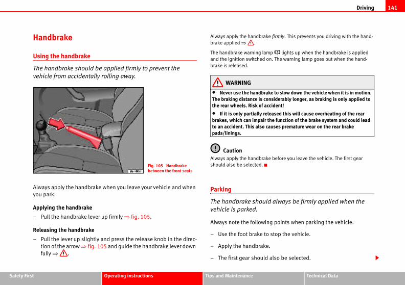
Driving 141
Safety Fir Technical Data
firmly. This prevents you driving with the hand-
lights up when the handbrake is applied
. The warning lamp goes out when the hand-
to slow down the vehicle when it is in motion. iderably longer, as braking is only applied to dent!
sed this will cause overheating of the rear e function of the brake system and could lead ses premature wear on the rear brake
before you leave the vehicle. The first gear
always be firmly applied when the
points when parking the vehicle:
top the vehicle.
lso be selected.
st Operating instructions Tips and Maintenance
Handbrake
Using the handbrake
The handbrake should be applied firmly to prevent the
vehicle from accidentally rolling away.
Always apply the handbrake when you leave your vehicle and when
you park.
Applying the handbrake
– Pull the handbrake lever up firmly ⇒ fig. 105.
Releasing the handbrake
– Pull the lever up slightly and press the release knob in the direc-
tion of the arrow ⇒ fig. 105 and guide the handbrake lever down
fully ⇒ .
Always apply the handbrake
brake applied ⇒ .
The handbrake warning lamp
and the ignition switched on
brake is released.
WARNING
• Never use the handbrakeThe braking distance is consthe rear wheels. Risk of acci
• If it is only partially releabrakes, which can impair thto an accident. This also caupads/linings.
CautionAlways apply the handbrake
should also be selected.
Parking
The handbrake should
vehicle is parked.
Always note the following
– Use the foot brake to s
– Apply the handbrake.
– The first gear should a
Fig. 105 Handbrake between the front seats
Driving142
tem (CCS)*
is able to maintain the set speed in
30 km/h to 180 km/h.
en saved, you may take your foot off the accel-
the cruise control system if it is not possible
ise control system should not be used in bends or where roads conditions are poor pings, slippery surfaces, snow). Risk of acci-
when you have finished using it. This will ke.
t speed which is too high for the current road, . Risk of accident.
tain a constant speed when descending gradi-
te under its own weight. Use the foot brake to
– Switch off the engine and remove the key from the ignition lock.
Turn the steering wheel slightly to engage the steering lock.
– Always take you car keys with you when you leave the vehicle
⇒ .
Additional notes on parking the vehicle on gradients:
Turn the steering wheel so that the vehicle would roll against the kerb if it did
start to roll.
• If the vehicle is facing downhill, turn the front wheels so that they point
towards the kerb.
• If the vehicle is facing uphill, turn the front wheels so that they point away
from the kerb.
• Secure the vehicle as normal by applying the handbrake firmly and
selecting first gear.
WARNING
• Take measures to reduce the risk of injury when you leave your vehicle unattended.
• Never park where the hot exhaust system could ignite inflammable materials, such as dry grass, low bushes, spilt fuel etc.
• Never allow vehicle occupants to remain in the vehicle when it is locked. They would be unable to open the vehicle from the inside, and could become trapped in the vehicle in an emergency. In the event of an emergency, locked doors will delay assistance to occupants.
• Never leave children unsupervised in the vehicle. They could set the vehicle in motion, for example, by releasing the handbrake or the gear lever / selector lever.
• Depending on weather conditions, it may become extremely hot or cold inside the vehicle. This can be fatal.
Cruise control sys
Description
The cruise control system
the range from approx.
Once the speed setting has be
erator.
WARNING
It could be dangerous to useto drive at constant speed.
• For safety reasons the crudense traffic, in sections with(e.g. aquaplaning, loose chipdent.
• Always switch off the CCSprevent you using it by mista
• It is dangerous to use a setraffic or weather conditions
NoteThe cruise control cannot main
ents. The vehicle will accelera
slow the vehicle.
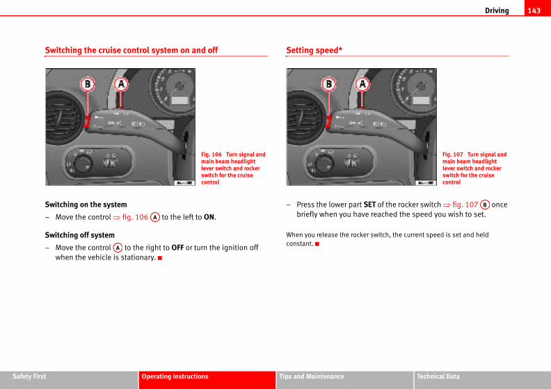
Driving 143
Safety Fir Technical Data
T of the rocker switch ⇒ fig. 107 once
reached the speed you wish to set.
switch, the current speed is set and held
Fig. 107 Turn signal and main beam headlight lever switch and rocker switch for the cruise control
AB
st Operating instructions Tips and Maintenance
Switching the cruise control system on and off
Switching on the system
– Move the control ⇒ fig. 106 to the left to ON.
Switching off system
– Move the control to the right to OFF or turn the ignition off
when the vehicle is stationary.
Setting speed*
– Press the lower part SEbriefly when you have
When you release the rocker
constant.
Fig. 106 Turn signal and main beam headlight lever switch and rocker switch for the cruise control
AA
AA
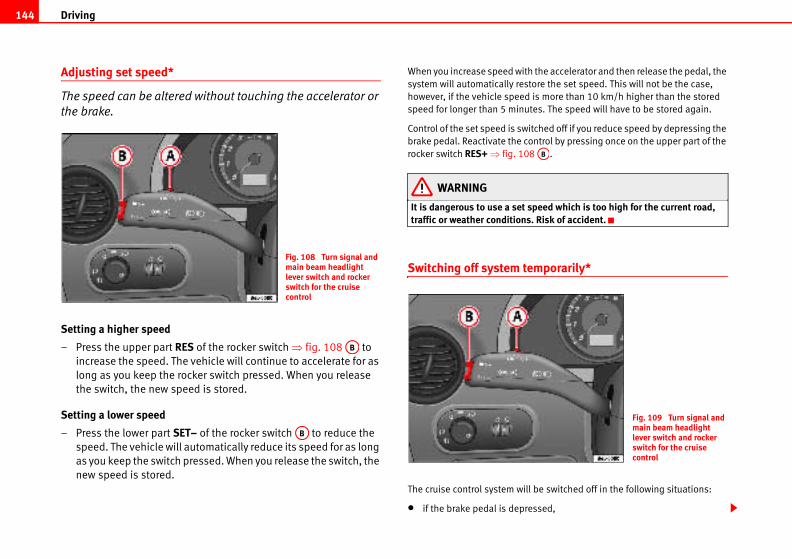
Driving144
the accelerator and then release the pedal, the
ore the set speed. This will not be the case,
is more than 10 km/h higher than the stored
es. The speed will have to be stored again.
tched off if you reduce speed by depressing the
ntrol by pressing once on the upper part of the
.
peed which is too high for the current road, . Risk of accident.
mporarily*
be switched off in the following situations:
ssed,
AB
Fig. 109 Turn signal and main beam headlight lever switch and rocker switch for the cruise control
Adjusting set speed*
The speed can be altered without touching the accelerator or
the brake.
Setting a higher speed
– Press the upper part RES of the rocker switch ⇒ fig. 108 to
increase the speed. The vehicle will continue to accelerate for as
long as you keep the rocker switch pressed. When you release
the switch, the new speed is stored.
Setting a lower speed
– Press the lower part SET– of the rocker switch to reduce the
speed. The vehicle will automatically reduce its speed for as long
as you keep the switch pressed. When you release the switch, the
new speed is stored.
When you increase speed with
system will automatically rest
however, if the vehicle speed
speed for longer than 5 minut
Control of the set speed is swi
brake pedal. Reactivate the co
rocker switch RES+ ⇒ fig. 108
WARNING
It is dangerous to use a set straffic or weather conditions
Switching off system te
The cruise control system will
• if the brake pedal is depre
Fig. 108 Turn signal and main beam headlight lever switch and rocker switch for the cruise control
AB
AB
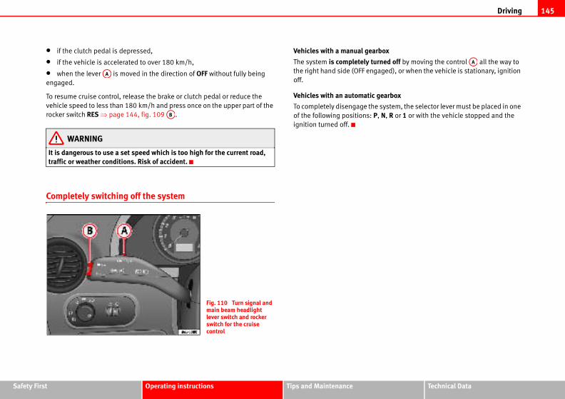
Driving 145
Safety Fir Technical Data
ox
ned off by moving the control all the way to
ged), or when the vehicle is stationary, ignition
earbox
system, the selector lever must be placed in one
N, R or 1 or with the vehicle stopped and the
AA
st Operating instructions Tips and Maintenance
• if the clutch pedal is depressed,
• if the vehicle is accelerated to over 180 km/h,
• when the lever is moved in the direction of OFF without fully being
engaged.
To resume cruise control, release the brake or clutch pedal or reduce the
vehicle speed to less than 180 km/h and press once on the upper part of the
rocker switch RES ⇒ page 144, fig. 109 .
WARNING
It is dangerous to use a set speed which is too high for the current road, traffic or weather conditions. Risk of accident.
Completely switching off the system
Vehicles with a manual gearb
The system is completely turthe right hand side (OFF enga
off.
Vehicles with an automatic g
To completely disengage the
of the following positions: P,
ignition turned off.
AA
AB
Fig. 110 Turn signal and main beam headlight lever switch and rocker switch for the cruise control

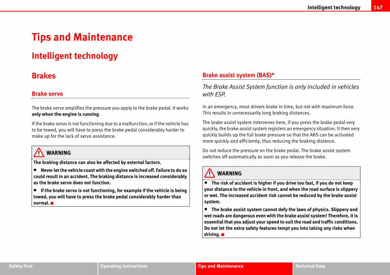
Intelligent technology 147
Safety Fir Technical Data
AS)*
function is only included in vehicles
s brake in time, but not with maximum force.
long braking distances.
venes here, if you press the brake pedal very
m registers an emergency situation. It then very
ke pressure so that the ABS can be activated
thus reducing the braking distance.
n the brake pedal. The brake assist system
soon as you release the brake.
gher if you drive too fast, if you do not keep in front, and when the road surface is slippery nt risk cannot be reduced by the brake assist
cannot defy the laws of physics. Slippery and n with the brake assist system! Therefore, it is r speed to suit the road and traffic conditions. atures tempt you into taking any risks when
st Operating instructions Tips and Maintenance
Tips and Maintenance
Intelligent technology
Brakes
Brake servo
The brake servo amplifies the pressure you apply to the brake pedal. It works
only when the engine is running.
If the brake servo is not functioning due to a malfunction, or if the vehicle has
to be towed, you will have to press the brake pedal considerably harder to
make up for the lack of servo assistance.
WARNING
The braking distance can also be affected by external factors.
• Never let the vehicle coast with the engine switched off. Failure to do so could result in an accident. The braking distance is increased considerably as the brake servo does not function.
• If the brake servo is not functioning, for example if the vehicle is being towed, you will have to press the brake pedal considerably harder than normal.
Brake assist system (B
The Brake Assist System
with ESP.
In an emergency, most driver
This results in unnecessarily
The brake assist system inter
quickly, the brake assist syste
quickly builds up the full bra
more quickly and efficiently,
Do not reduce the pressure o
switches off automatically as
WARNING
• The risk of accident is hiyour distance to the vehicleor wet. The increased accidesystem.
• The brake assist systemwet roads are dangerous eveessential that you adjust youDo not let the extra safety fedriving.
Intelligent technology148
is also determined by the tyres fitted
es are modified, the effectiveness of the ABS
(TCS)*
em prevents the drive wheels from
s accelerating. The system always
he traction control system during acceleration
help prevent the drive wheels of front-wheel
during acceleration. The system works in the
tion with ABS. If a malfunction should occur in
ut of action.
oving, accelerate and climb a gradient in slip-
y otherwise be difficult or even impossible.
tically when the engine is started. If necessary,
hing the button on the centre console.
ng lamp is lit. The TCS should normally be left
in exceptional circumstances, when slipping of
it be disconnected, for example
pare wheel.
ns.
or on loose surfaces.
d-down, to free it by “rocking.”
Anti-lock brake system and traction control ABS
Anti-lock brake system (ABS)
The anti-lock brake system prevents the wheels locking
during braking.
The anti-lock brake system (ABS) is an important part of the vehicle’s active
safety system.
How the ABS works
If one of the wheels is turns too slowly in relation to the road speed, and is
close to locking, the system will reduce the braking pressure for this wheel.
The driver is made aware of this control process by a pulsating of the brake pedal and audible noise. This is a deliberate warning to the driver that one or
more of the wheels is tending to lock and the ABS control function has inter-
vened. In this situation it is important to keep the brake pedal fully depressed
so the ABS can regulate the brake application. Do not “pump”.
If you brake hard on a slippery road surface, the best possible control is
retained as the wheels do not lock.
However, ABS will not necessarily guarantee shorter braking distances in all
conditions. The braking distance could even be longer if you brake on gravel
or on fresh snow covering a slippery surface.
WARNING
• The anti-lock brake system cannot defy the laws of physics. Slippery and wet roads are dangerous even with ABS! If you notice that the ABS is working (to counteract locked wheels under braking), you should reduce speed immediately to suit the road and traffic conditions. Do not let the extra safety features tempt you into taking any risks when driving.
• The effectiveness of ABS ⇒ page 196.
• If the running gear or brakcould be severely limited.
Traction control system
The traction control syst
spinning when the car i
includes ABS
Description and operation of t(TCS)
TCS reduces engine power to
drive vehicles losing traction
entire speed range in conjunc
the ABS, the TCS will also be o
TCS helps the vehicle to start m
pery conditions where this ma
The TCS is switched on automa
it may be turned on or off pus
When the TCS is off, the warni
switched on at all times. Only
the wheels is required, should
• With compact temporary s
• When using the snow chai
• When driving in deep snow
• When the vehicle is bogge
WARNING (continued)
Intelligent technology 149
Safety Fir Technical Data
m (ESP)*
idding by braking the wheels individually.
wheel angle and road speed to calculate the
by the driver, and constantly compares them
the vehicle. If the desired course is not being
e car is starting to skid), then the ESP compen-
g the appropriate wheel.
ed wheel bring the vehicle back to a stable
s to oversteer, the system will act on the front
urn.
hat ESP cannot defy the laws of physics. This ticularly on slippery and wet roads and when
g style to suit the condition of the roads and let the extra safety afforded by ESP tempt you riving, this can cause accidents.
P functions correctly, all four wheels must be
y differences in the rolling radius of the tyres can
ngine power when this is not desired.
le (e.g. to the engine, the brake system, running
cting the wheels and tyres) could affect the effi-
nd TCS.
button ⇒ page 131.
st Operating instructions Tips and Maintenance
The TCS should be switched on again afterwards as soon as possible.
WARNING
• It must be remembered that TCS cannot defy the laws of physics. This should be kept in mind, particularly on slippery and wet roads and when towing a trailer.
• Always adapt your driving style to suit the condition of the roads and the traffic situation. Do not let the extra safety afforded by TCS tempt you into taking any risks when driving, this can cause accidents.
Caution• In order to ensure that TCS function correctly, all four wheels must be
fitted with the same tyres. Any differences in the rolling radius of the tyres can
cause the system to reduce engine power when this is not desired.
• Modifications to the vehicle (e.g. to the engine, the brake system, running
gear or any components affecting the wheels and tyres) could affect the effi-
ciency of the ABS and TCS.
Electronic stabilisation programme (ESP)*
General notes
The electronic stabilisation programme increases the
vehicle’s stability on the road.
The electronic stabilisation programme helps to reduce the danger of skid-
ding.
The electronic stabilisation programme (ESP) consists of ABS, EDL and TCS.
Electronic Stabilising Progra
ESP reduces the danger of sk
The system uses the steering
changes of direction desired
with the actual behaviour of
maintained (for instance, if th
sates automatically by brakin
The forces acting on the brak
condition. If the vehicle tend
wheel on the outside of the t
WARNING
• It must be remembered tshould be kept in mind, partowing a trailer.
• Always adapt your drivinthe traffic situation. Do not into taking any risks when d
Caution• In order to ensure that ES
fitted with the same tyres. An
cause the system to reduce e
• Modifications to the vehic
gear or any components affe
ciency of the ABS, EDL, ESP a
NoteTo disconnect using the ESP
Intelligent technology150
style to suit road conditions and the traffic safety afforded by EDL tempt you into taking an cause accidents.
.g. to the engine, the brake system, running
ting the wheels and tyres) could affect the effi-
.
tem (TCS)
vents the drive wheels from spinning when the
8.
Anti-lock brake system (ABS)
The anti-lock brake system prevents the wheels locking during braking
⇒ page 148.
Electronic differential lock (EDL)*
The electronic differential lock helps prevent the loss of trac-
tion caused if one of the driven wheels starts spinning.
EDL helps the vehicle to start moving, accelerate and climb a gradient in slip-
pery conditions where this may otherwise be difficult or even impossible.
The system will control the revolutions of the drive wheels using the ABS
sensors (in case of an EDL fault the warning lamp for ABS lights up)
⇒ page 64.
At speeds of up to approximately 80 km/h, it is able to balance out differ-
ences in the speed of the driven wheels of approximately 100 rpm caused by
a slippery road surface on one side of the vehicle. It does this by braking the
wheel which has lost traction and distributing more driving force to the other
driven wheel via the differential.
To prevent the disc brake of the braked wheel from overheating, the EDL cuts
out automatically if subjected to excessive loads. The vehicle will continue to
function normally without EDL. For this reason, the driver is not informed that
the EDL has been switched off.
The EDL will switch on again automatically when the brake has cooled down.
WARNING
• When accelerating on a slippery surface, for example on ice and snow, press the accelerator carefully. Despite EDL, the driven wheels may start to spin. This could impair the vehicle’s stability.
• Always adapt your drivingsituation. Do not let the extraany risks when driving, this c
CautionModifications to the vehicle (e
gear or any components affec
ciency of the EDL ⇒ page 172
The traction control sys
The traction control system pre
car is accelerating ⇒ page 14
WARNING (continued)
Driving and the environment 151
Safety Fir Technical Data
ion)
ugh puddles and passages of water must not
rake pads
n-in carefully for the first 500 km. New
un-in carefully for the first 200 km.
can compensate for the reduced braking effect
the brake pedal. If you need to make an emer-
nce will be longer with new brake pads than with
run-in.
ximum grip to start with, and require running-nt. Drive particularly carefully in the first 500
“run in” and do not have the correct friction 00 km. However, the reduced braking capacity ssing on the brake pedal a little harder.
st Operating instructions Tips and Maintenance
Driving and the environment
Running-in
Running in a new engine
The engine needs to be run-in over the first 1,500 km.
Up to 1,000 kilometres
– Do not drive faster than three quarters of top speed.
– Do not accelerate hard.
– Avoid high engine revolutions.
– Do not tow a trailer.
From 1000 to 1500 km
– Speeds can be gradually increased to the maximum road speed
or maximum permissible engine speed (rpm).
During its first few hours of running, the internal friction in the engine is
greater than later on when all the moving parts have bedded in.
For the sake of the environmentIf the engine is run in gently, the life of the engine will be increased and its oil
consumption reduced.
Deep water (Cupra vers
The speed of the vehicle thro
exceed 25 km/h.
Running in tyres and b
New tyres should be ru
brake pads should be r
During the first 200 km, you
by applying more pressure to
gency stop, the braking dista
brake pads which have been
WARNING
• New tyres do not give main. This may cause an accidekm.
• New brake pads must beproperties during the first 2may be compensated by pre
Driving and the environment152
” by applying light pressure. Continuous to overheat and will increase the braking ase the brakes alternately.
t with the engine switched off. The braking rably as the brake servo does not function.
kes may cause a vapour lock if the brake fluid ng. This impairs the braking effect.
front spoilers could restrict the airflow to the erheat. Observe the relevant instructions s ⇒ page 172, “Modifications”.
braking distance will be increased consider-kshop immediately and avoid unnecessary
rification system
of the catalytic converter
etrol.
dry.
do not replenish with too much engine oil
up engine oil ”.
o start it, use jump leads if necessary
Braking effect and braking distance
The braking effect and braking distance are influenced by
driving situations and road conditions.
The efficiency of the brakes depends directly on the brake pad wear. The rate
of wear of the brake pads depends to a great extent on the conditions under
which the vehicle is operated and the way the vehicle is driven. If you often
drive in town traffic, drive short distances or have a sporty driving style, we
recommend that you have the thickness of your brake pads checked by an
Authorised Service Centre more frequently than recommended in the Service
Schedule.
If you drive with wet brakes, for example, after crossing areas of water, in
heavy rainfall or even after washing the car, the effect of the brakes is less-
ened as the brake discs are wet or even frozen (in winter): The brakes should
be “dried” by pressing the pedal to restore full braking effect.
WARNING
Longer braking distances and faults in the brake system increase the risk of accidents.
• New brake pads must be run in and do not have the correct friction during the first 200 km. However, the reduced braking capacity may be compensated by pressing on the brake pedal a little harder. This also applies when new brake pads are fitted.
• If brakes are wet or frozen, or if you are driving on roads which have been gritted with salt, braking power may set in later than normal.
• On steep descents if the brakes are excessively used they will over heat. Before driving down a long steep gradient, it is advisable to reduce speed and change to a lower gear (or move the selector lever to a lower gear if your vehicle has automatic transmission). This makes use of engine braking and relieves the brakes.
• Never let the brakes “rubbraking will cause the brakesdistance. Apply and then rele
• Never let the vehicle coasdistance is increased conside
• Very heavy use of the brais left in the system for too lo
• Non-standard or damagedbrakes and cause them to ovbefore purchasing accessorie
• If a brake circuit fails, theably. Contact a qualified worjourneys.
Exhaust gasses pu
Catalytic converter*
To conserve the useful life
– Always use unleaded p
– Do not run the fuel tank
– For engine oil changes,
⇒ page 186, “Topping
– Never tow the vehicle t
⇒ page 230.
WARNING (continued)
Driving and the environment 153
Safety Fir Technical Data
te filter*
culate filter eliminates soot produced
liminates most of the soot from the exhaust gas
conditions, the filter cleans itself. If the driving
ilter to clean itself (for example, multiple short
ted by dust and pollen and the indicator for
filter indicator will light. See under Warning
ulate filter may reach extremely high tempera-o contact with flammable materials under- comply could result in fire.
el engine particulate filter must not be refueled
that the fuel system may be damaged.
ing must be taken into consideration:
atalytic converter ensure that unleaded petrol is
the chapter “Refuelling”. Automobile organisa-
st Operating instructions Tips and Maintenance
If you notice misfiring, uneven running or loss of power when the vehicle is
moving, reduce speed immediately and have the vehicle inspected at the
nearest qualified workshop. In general, the exhaust warning lamp will light
up when any of the described symptoms occur ⇒ page 60. If this happens,
unburnt fuel can enter the exhaust system and escape into the environment.
The catalytic converter can also be damaged by overheating.
WARNING
The catalytic converter reaches very high temperatures! Fire hazard!
• Never park where the catalytic converter could come into contact with dry grass or inflammable materials under the vehicle.
• Do not apply additional underseal or anti-corrosion coatings to the exhaust pipes, catalytic converter or the heat shields on the exhaust system. These materials could catch fire when the vehicle is driven.
CautionNever fully drain the fuel tank, in this case, the irregularity of the fuel supply
may cause ignition problems. This allows unburnt fuel to enter the exhaust
system, which could cause overheating and damage the catalytic converter.
For the sake of the environmentEven when the emission control system is working perfectly, there may be a
smell of sulphur from the exhaust under some conditions. This depends on
the sulphur content of the fuel used. Quite often the problem can be reme-
died by changing to another brand of fuel.
Diesel engine particula
The diesel engine parti
by burning diesel.
The diesel engine dust filter e
system. Under normal driving
conditions do not allow the f
trips) the filter will be obstruc
the diesel engine particulate
Lights.
WARNING
• The diesel engine partictures; it should not enter intneath the vehicle. Failure to
CautionVehicles equipped with a dies
using biodiesel (RME), given
Driving abroad
Notes
For driving abroad, the follow
• For vehicles fitted with a c
available for the journey. See
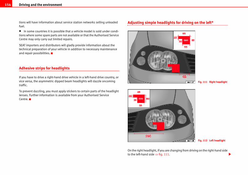
Driving and the environment154
ights for driving on the left*
re changing from driving on the right-hand side
1.
Fig. 111 Right headlight
Fig. 112 Left headlight
tions will have information about service station networks selling unleaded
fuel.
• In some countries it is possible that a vehicle model is sold under condi-
tions where some spare parts are not available or that the Authorised Service
Centre may only carry out limited repairs.
SEAT importers and distributors will gladly provide information about the
technical preparation of your vehicle in addition to necessary maintenance
and repair possibilities.
Adhesive strips for headlights
If you have to drive a right-hand drive vehicle in a left-hand drive country, or
vice versa, the asymmetric dipped beam headlights will dazzle oncoming
traffic.
To prevent dazzling, you must apply stickers to certain parts of the headlight
lenses. Further information is available from your Authorised Service
Centre.
Adjusting simple headl
On the right headlight, if you a
to the left-hand side ⇒ fig. 11
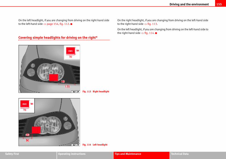
Driving and the environment 155
Safety Fir Technical Data
are changing from driving on the left-hand side
113.
e changing from driving on the left-hand side to
4.
st Operating instructions Tips and Maintenance
On the left headlight, if you are changing from driving on the right-hand side
to the left-hand side ⇒ page 154, fig. 112.
Covering simple headlights for driving on the right*
On the right headlight, if you
to the right-hand side ⇒ fig.
On the left headlight, if you ar
the right-hand side ⇒ fig. 11
Fig. 113 Right headlight
Fig. 114 Left headlight
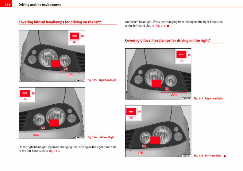
Driving and the environment156
e changing from driving on the right-hand side
6.
mps for driving on the right*
Fig. 117 Right headlight
Fig. 118 Left headlight
Covering bifocal headlamps for driving on the left*
On the right headlight, if you are changing from driving on the right-hand side
to the left-hand side ⇒ fig. 115.
On the left headlight, if you ar
to the left-hand side ⇒ fig. 11
Covering bifocal headla
Fig. 115 Right headlight
Fig. 116 Left headlight
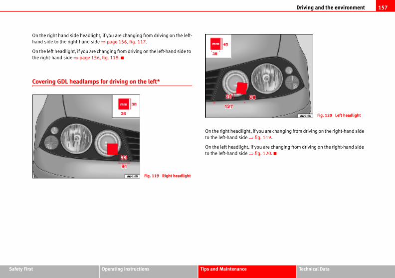
Driving and the environment 157
Safety Fir Technical Data
are changing from driving on the right-hand side
19.
re changing from driving on the right-hand side
20.
Fig. 120 Left headlight
st Operating instructions Tips and Maintenance
On the right hand side headlight, if you are changing from driving on the left-
hand side to the right-hand side ⇒ page 156, fig. 117.
On the left headlight, if you are changing from driving on the left-hand side to
the right-hand side ⇒ page 156, fig. 118.
Covering GDL headlamps for driving on the left*
On the right headlight, if you
to the left-hand side ⇒ fig. 1
On the left headlight, if you a
to the left-hand side ⇒ fig. 1
Fig. 119 Right headlight
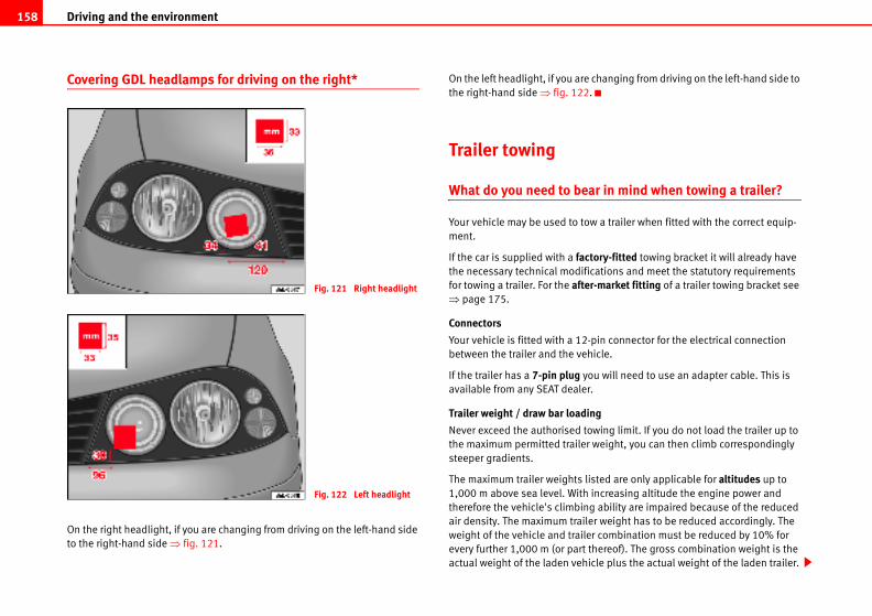
Driving and the environment158
changing from driving on the left-hand side to
.
ar in mind when towing a trailer?
w a trailer when fitted with the correct equip-
ctory-fitted towing bracket it will already have
ications and meet the statutory requirements
er-market fitting of a trailer towing bracket see
-pin connector for the electrical connection
hicle.
ou will need to use an adapter cable. This is
r.
ing
owing limit. If you do not load the trailer up to
r weight, you can then climb correspondingly
listed are only applicable for altitudes up to
increasing altitude the engine power and
g ability are impaired because of the reduced
ler weight has to be reduced accordingly. The
er combination must be reduced by 10% for
thereof). The gross combination weight is the
icle plus the actual weight of the laden trailer.
Covering GDL headlamps for driving on the right*
On the right headlight, if you are changing from driving on the left-hand side
to the right-hand side ⇒ fig. 121.
On the left headlight, if you are
the right-hand side ⇒ fig. 122
Trailer towing
What do you need to be
Your vehicle may be used to to
ment.
If the car is supplied with a fathe necessary technical modif
for towing a trailer. For the aft⇒ page 175.
Connectors
Your vehicle is fitted with a 12
between the trailer and the ve
If the trailer has a 7-pin plug y
available from any SEAT deale
Trailer weight / draw bar load
Never exceed the authorised t
the maximum permitted traile
steeper gradients.
The maximum trailer weights
1,000 m above sea level. With
therefore the vehicle's climbin
air density. The maximum trai
weight of the vehicle and trail
every further 1,000 m (or part
actual weight of the laden veh
Fig. 121 Right headlight
Fig. 122 Left headlight
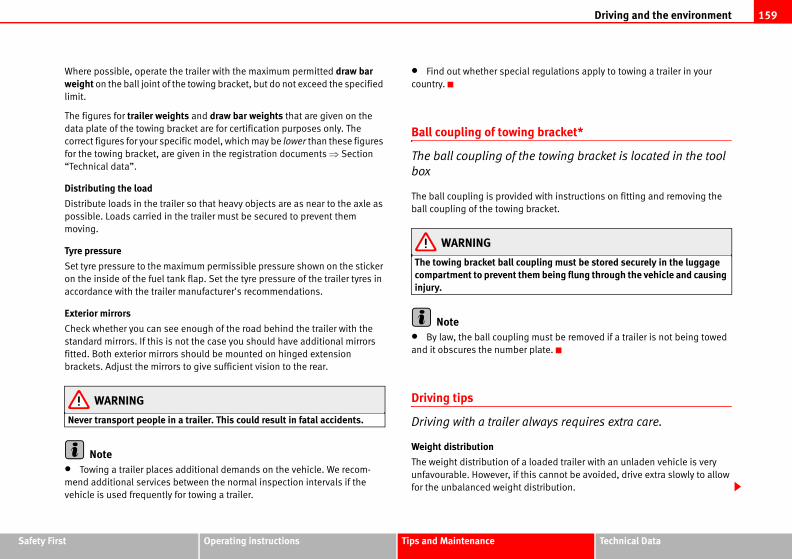
Driving and the environment 159
Safety Fir Technical Data
regulations apply to towing a trailer in your
bracket*
towing bracket is located in the tool
with instructions on fitting and removing the
racket.
pling must be stored securely in the luggage m being flung through the vehicle and causing
must be removed if a trailer is not being towed
late.
ways requires extra care.
oaded trailer with an unladen vehicle is very
s cannot be avoided, drive extra slowly to allow
stribution.
st Operating instructions Tips and Maintenance
Where possible, operate the trailer with the maximum permitted draw bar weight on the ball joint of the towing bracket, but do not exceed the specified
limit.
The figures for trailer weights and draw bar weights that are given on the
data plate of the towing bracket are for certification purposes only. The
correct figures for your specific model, which may be lower than these figures
for the towing bracket, are given in the registration documents ⇒ Section
“Technical data”.
Distributing the load
Distribute loads in the trailer so that heavy objects are as near to the axle as
possible. Loads carried in the trailer must be secured to prevent them
moving.
Tyre pressure
Set tyre pressure to the maximum permissible pressure shown on the sticker
on the inside of the fuel tank flap. Set the tyre pressure of the trailer tyres in
accordance with the trailer manufacturer's recommendations.
Exterior mirrors
Check whether you can see enough of the road behind the trailer with the
standard mirrors. If this is not the case you should have additional mirrors
fitted. Both exterior mirrors should be mounted on hinged extension
brackets. Adjust the mirrors to give sufficient vision to the rear.
WARNING
Never transport people in a trailer. This could result in fatal accidents.
Note• Towing a trailer places additional demands on the vehicle. We recom-
mend additional services between the normal inspection intervals if the
vehicle is used frequently for towing a trailer.
• Find out whether special
country.
Ball coupling of towing
The ball coupling of the
box
The ball coupling is provided
ball coupling of the towing b
WARNING
The towing bracket ball coucompartment to prevent theinjury.
Note• By law, the ball coupling
and it obscures the number p
Driving tips
Driving with a trailer al
Weight distribution
The weight distribution of a l
unfavourable. However, if thi
for the unbalanced weight di
Driving and the environment160
tions to "alleviate" some of the strain in the
time, your wallet.
well in advance
accelerating. When you anticipate the situa-
s often and, thus, accelerate less. If it is
th a gear engaged, for example, if you see a red
rgy
l is to change up through the gears quickly.
m in the lower gears uses an unnecessary
first to second gear as quickly as possible. We
ssible, you change to a higher gear upon
e slowly and avoid the “kick-down” position.
the top speed permitted by the vehicle. Fuel
ns and noise levels all increase very rapidly at
erate speeds will help to save fuel.
he engine when waiting in a traffic jam, at level
ith a long red phase. The fuel saved after only
n the amount of fuel needed to restart the
ime to warm up when it is running at idling
ollutant emissions are also especially high
ase. It is therefore best to drive off immediately
d running the engine at high speed.
Speed
The stability of the vehicle and trailer is reduced with increasing speed. For
this reason it is advisable not to drive at the maximum permissible speed in
unfavourable road, weather or wind conditions. This applies especially when
driving downhill.
You should always reduce speed immediately if the trailer shows the slightest
sign of snaking. Never try to stop the “snaking” by increasing speed.
Always brake in good time. If the trailer has an overrun brake, apply the
brakes gently at first and then firmly. This will prevent the jerking that can be
caused by the trailer wheels locking. Select a low gear in good time before
going down a steep descent. This enables you to use the engine braking to
slow down the vehicle.
Heating
At very high temperatures and during prolonged ascents, driving in a low gear
and high engine speed, always monitor the temperature indicator for the
coolant ⇒ page 51.
Electronic Stabilisation Program*
Do not switch off the ESP* when towing a trailer. The ESP* makes it easier to
stabilise if the trailer starts to snake.
Driving economically and with respect for the environment
General Observations
Fuel consumption, environmental pollution and wear to the engine, brakes
and tyres depends in large part on your driving style. Fuel consumption may
be reduced from 10 to 15 % by driving defensively and economically. Below
we will give you some sugges
environment and, at the same
Anticipate the traffic situation
A vehicle uses most fuel when
tion, you will have to brake les
possible, let the vehicle roll wi
light ahead.
Change gear early to save ene
An effective way of saving fue
Running the engine at high rp
amount of fuel.
Manual gearbox: Change from
recommend that, whenever po
reaching 2,000 rpms.
Automatic gearbox: Accelerat
Avoid driving at high speed
We advise you not to drive at
consumption, exhaust emissio
higher speeds. Driving at mod
Avoid idling
It is worthwhile switching off t
crossings or at traffic lights w
30 - 40 seconds is greater tha
engine.
The engine takes a very long t
speed. Mechanical wear and p
during this initial warm-up ph
after starting the engine. Avoi
Driving and the environment 161
Safety Fir Technical Data
l put up the fuel consumption, so it is worth
rtment occasionally to make sure that no unnec-
orted.
nator, which produces electricity. With the need
on is also increased. Because of this, always
when you do not need them. Examples of equip-
ity are: the fan at high speeds, the rear window
ck on fuel consumption is to take regular notes.
riations (both positive and negative) and react
ness
top priority in the design, choice of materials
eat.
ical recycling
signed for ease of dismantling
acilitate dismantling
rade materials
ers are labelled in accordance with ISO 1043,
can be recycled
rouped together for easy recycling
st Operating instructions Tips and Maintenance
Periodic maintenance
Periodic maintenance work guarantees that, before beginning a journey, you
will not waste fuel. A well-serviced engine gives you the benefit of improved fuel efficiency as well as maximum reliability and an enhanced resale value.
A maladjusted engine may mean an increase of 10 % over normal fuel
consumption.
Check the oil level every time you fill the tank. Oil consumption depends to a
great extent on the engine load and engine speed. It is quite normal that the
oil consumption of a new engine only reaches its lowest level after a certain
mileage. This means that the oil consumption can only be properly assessed
after about 5,000 km. Depending on your personal driving style, oil consump-
tion can be up to 0.5 litres per 1,000 km.
Avoid short journeys
To reduce the consumption and emission of polluting gases, the engine and
the exhaust filtration systems should reach the optimum service tempera-ture.
With the engine cold, fuel consumption is proportionally higher. The engine
does not warm up and fuel consumption does not regularise until having
driven some four kilometres. This is the reason why we recommend avoiding
short trips wherever possible.
Maintain the correct tyre pressures
Bear in mind that keeping the tyres at an adequate pressure saves fuel. If the
tyre pressures are just 1 bar too low, this can put the fuel consumption up by
as much as 5 %. Due to the greater rolling resistance, under-inflation also
increases tyre wear and impairs handling.
The tyre pressures should always be checked when the tyres are cold.
Do not use winter tyres all through the year: they will increase fuel consump-
tion by up to 10 %.
Avoid unnecessary weight
Every kilo of extra weight wil
checking the luggage compa
essary loads are being transp
Save electrical energy
The engine activates the alter
for electricity, fuel consumpti
turn off electrical equipment
ment that use a lot of electric
heating or the seat heaters*.
Logbook
A good way of keeping a che
You will be able to note the va
accordingly.
Environmental friendli
Environmental protection is a
and production of your new S
Design measures for econom
• Joints and connections de
• Modular construction to f
• Increased use of single-g
• Plastic parts and elastom
ISO 11469 and ISO 1629
Choice of materials
• Nearly all materials used
• Similar types of plastics g
Driving and the environment162
• Recycled materials used in manufacture
• Reduced “vapour emissions” from plastics
• CFC-free refrigerant in air conditioning
Compliance with prohibited materials laws: cadmium, asbestos, lead,
mercury, chrome VI.
Manufacturing methods
• Use of recycled material for manufacturing plastic parts
• Solvent-free cavity sealing
• Solvent-free wax for protecting the vehicles in transit
• Solvent-free adhesives
• No CFCs used in production
• Surplus materials used extensively for energy conversion and building
materials
• Overall water consumption reduced
• Heat recovery systems
• Water-soluble paint
Cleaning and caring for your vehicle 163
Safety Fir Technical Data
ain products may produce noxious vapours; l ventilated areas.
e, engine oil, nail varnish remover or other ic and highly flammable. There is a fire / explo-
hicle, or carry out any maintenance, switch off rake firmly and remove the key from the igni-
, mud or dust if the surface of the vehicle is dry.
e for cleaning purposes. This could damage the
hicle. Soak dirt, mud or dust with plenty of
nvironment products, try to select ones which are not
should not be disposed of with ordinary house-
osal information on the package.
st Operating instructions Tips and Maintenance
Cleaning and caring for your vehicle
General notes
Regular washing and care help maintain the value of your
vehicle.
Regular care
Regular and expert care helps to maintain the value of the vehicle. This may
also be one of the requirements for acknowledging warranty claims in the
event of corrosion or paint defects.
The best way to protect the car against environmental contaminants is to
wash and wax it frequently. The longer substances such as insects, bird drop-
pings, resinous tree sap, road dirt, industrial deposits, tar, soot or road salt
and other aggressive materials remain on the vehicle, the more damage they
do to the paintwork. High temperatures (for instance in strong sunlight)
further intensify the corrosive effect.
After the period when salt is put on the roads it is important to have the
underside of the vehicle washed thoroughly.
Car care products
Car care products are available from your Authorised Service Centre. Keep the
product instructions until you have used up the product.
WARNING
• Car care products can be toxic. For this, they must always be kept closed in their original container. Keep out of children's reach. Failure to comply could result in poisoning.
• Always read and observe the instructions and warnings on the package before using car care products. Improper use could damage your health or
your vehicle. The use of certthese should be used in wel
• Never use fuel, turpentinvolatile fluids. These are toxsion risk.
• Before you wash your vethe engine, apply the handbtion.
CautionNever attempt to remove dirt
Never use a dry cloth or spong
paintwork or glass on your ve
water.
For the sake of the e• When purchasing car care
harmful to the environment.
• Left over car care products
hold waste. Observe the disp
WARNING (continued)
Cleaning and caring for your vehicle164
soft sponge, a glove or a brush. Start on
way down. Use only light pressure.
ve as much as possible.
ould only be used for very stubborn dirt.
anels etc. last using a different sponge or
ughly with water.
ehicle gently using a chamois leather.
er seals and the surfaces they touch with
freezing. Apply silicone spray to the
en braking directly after washing the
the brakes by applying the brakes care-
age 152, “Braking effect and braking
be switched off before the vehicle is washed.
rms from cuts on sharp metal edges when inside of the wheel housings etc. Risk of
the brakes may affect braking efficiency. Risk
Care of the vehicle exterior
Automatic car washes
The paint is so durable that the car can normally be washed without problems
in an automatic car wash. However, the effect on the paint depends to a large
extent on the design of the car wash, the brushes used, the filtering of the
wash water and the type of detergents and wax solutions used, etc.
Before going through a car wash, be sure to take the usual precautions such
as closing the windows and sunroof. There is nothing to note apart from that.
If the vehicle has special accessories such as spoilers or a roof carrier or two-
way radio aerial, etc., it is advisable to consult the car wash operator.
After the car has been washed, the brakes could hesitate to respond as the
brake discs and pads will be wet, or even frozen in winter. “Dry ” the brakes
by braking several times.
WARNING
Moisture, ice and salt on the brakes may affect braking efficiency. Risk of accident.
CautionBefore putting the vehicle in a carwash tunnel, do not tighten the aerial if it is
folded as this may cause damage.
Washing by hand
Washing the vehicle
– First soften the dirt with plenty of water and rinse off.
– Clean the vehicle with a
the roof and work your
– Rinse the sponge or glo
– Special car shampoo sh
– Clean the wheels, sill p
glove.
– Rinse the vehicle thoro
– Dry the surface of the v
– If it is cold, dry the rubb
a cloth to prevent them
rubber seals.
After cleaning the vehicle
– If possible, avoid sudd
vehicle. You must “dry”
fully several times ⇒ p
distance”.
WARNING
• The ignition must always
• Protect your hands and acleaning the underbody, the injury.
• Moisture, ice and salt on of accident.
Cleaning and caring for your vehicle 165
Safety Fir Technical Data
sure cleaner to remove ice or snow from
d jet nozzles or so-called “dirt blasters”
en braking directly after washing the
” the brakes by applying the brakes care-
age 152.
concentrated jet or cylindrical jet (“rotating ing distances and short cleaning times, visible cur to the tyres. This may cause an accident.
the brakes may affect braking efficiency. Risk
an 60°C. This could damage the car.
hicle, maintain a sufficient distance from sensi-
xible hoses, plastic, sound proofing, etc. This is
pers painted in the same colour as the vehicle.
surface, the greater the wear on the material.
st Operating instructions Tips and Maintenance
Caution• Never attempt to remove dirt, mud or dust if the surface of the vehicle is
dry. Never use a dry cloth or sponge for cleaning purposes. This could scratch
the paintwork or glass on your vehicle.
• Washing the vehicle in low temperatures: if the vehicle is rinsed with a
hose, do not direct the water into the lock cylinders or the gaps around the
doors, luggage compartment, or bonnet. Otherwise there is a risk of malfunc-
tion.
For the sake of the environmentIn the interests of environmental protection, the car should be washed only
in specially provided wash bays. This prevents toxic, oil-laden waste water
entering the sewerage system. In some districts, washing vehicles anywhere
else may be prohibited.
NoteDo not wash the vehicle in direct sunlight.
Washing the car with a high pressure cleaner
Be particularly careful when using a high pressure cleaner!
– Always observe the instructions for the high-pressure cleaner,
particularly those concerning the pressure and the spraying distance.
– Increase the spraying distance for soft materials and painted
bumpers.
– Do not use a high pres
windows ⇒ page 166.
– Never use concentrate
⇒ .
– If possible, avoid sudd
vehicle. You must “dry
fully several times ⇒ p
WARNING
• Never wash tyres with a nozzle”). Even at large sprayand invisible damage can oc
• Moisture, ice and salt onof accident.
Caution
• Do not use water hotter th
• To avoid damage to the ve
tive materials for example: fle
especially important for bum
The closer the nozzle is to the
Cleaning and caring for your vehicle166
astic parts.
plastic parts, clean them with special solvent- products.
ner directly over the air vents of the vehicle may
e liquid is accidentally spilled.
ontain solvents will damage the material.
exterior mirrors
ith commercially available, alcohol based
clean chamois leather or a lint-free cloth.
ove snow from the windows and mirrors.
eather to dry the windows. Chamois leathers
ted surfaces are not suitable for use on
ith wax deposits which would smear the
Waxing the car
Regular waxing protects the paintwork.
You need to apply wax to your car if water does not form small drops and run
off the paintwork when it is clean.
Good quality hard wax is available from your Authorised Service Centre.
A good coat of wax helps to protects the paintwork from environmental
contaminants ⇒ page 163. It is also effective in protecting against minor
scratches.
Even if a wax solution is used regularly in the car wash, it is advisable to
protect the paint with a coat of hard wax at least twice a year.
Polishing the paintwork
Polishing brings back gloss to the paintwork.
Polishing is only necessary if the paint has lost its shine, and the gloss cannot
be brought back by applying wax. Polish can be obtained from your Author-
ised Service Centre.
The car must be waxed after polishing if the polish used does not contain wax
compounds to seal the paint ⇒ page 166, “Waxing the car”.
CautionTo prevent damage to the paintwork:
• Do not use polishes and hard wax on painted parts with a matte finish or
on plastic parts.
• Do not polish your vehicle in a sandy or dusty environment.
Caring for plastic parts
Solvents will damage pl
If normal washing fails to clean
free plastic cleaning and care
Caution• The use of liquid air freshe
damage the plastic parts if th
• Cleaning products which c
Cleaning windows and
Cleaning the windows
– Moisten the windows w
glass cleaner.
– Dry the windows with a
Removing snow
– Use a small brush to rem
Removing ice
– Use a de-icer spray.
Use a clean cloth or chamois l
which have been used on pain
windows. They will be soiled w
windows.
Cleaning and caring for your vehicle 167
Safety Fir Technical Data
looked after, they will not freeze so
ove dust and dirt from the rubber seals.
product to the rubber seals.
ors, windows, bonnet and rear lid will remain
are treated with a suitable care product (for
lso prevent premature ageing and leaks. The
f rubber seals are well looked after, they will not
can freeze up in winter.
ou should only use spray with lubricating and
th a damp cloth.
ith a soft, dry cloth.
st Operating instructions Tips and Maintenance
If possible use a de-icing spray to remove ice. If you use an ice scraper, push
it in one direction only. Do not move it to and fro.
Use window cleaner or a silicone remover to clean off rubber, oil, grease and
silicone deposits.
Wax deposits have to be removed with a special cleaner which is available
from your Authorised Service Centre. Wax deposits on the windscreen could
cause the wiper blades to judder. A window cleanser specifically for removing
wax will stop the blades juddering if added to the windscreen washer fluid.
Grease removing cleansers will not remove wax deposits.
Caution• Never use warm or hot water to remove snow and ice from windows and
mirrors. This could cause the glass to crack!
• The heating element for the rear window is located on the inner side of the
window. To prevent damage, do not put stickers over the heating elements on
the inside of the window.
Cleaning windscreen wiper blades
Clean wiper blades are essential for clear vision.
1. Use a soft cloth to remove dust and dirt from the windscreen
wiper blades.
2. Use window cleanser to clean the windscreen wiper blades. Use
a sponge or a cloth to remove stubborn stains.
Care of rubber seals
If rubber seals are well
quickly.
1. Use a soft cloth to rem
2. Apply a specialist care
The weather strips on the do
pliable and last longer if they
example silicone spray).
Caring for rubber seals will a
doors will be easier to open. I
freeze so quickly in winter.
Door lock cylinders
The door lock cylinders
To de-ice the lock cylinders y
anti-corrosive properties.
Cleaning chrome parts
1. Clean chrome parts wi
2. Polish chrome parts w
Cleaning and caring for your vehicle168
st from alloy wheels.
ent to clean the wheels.
ound to the wheels.
ttention to preserve their appearance. It is
and brake dust by washing the wheels at
e finish will be impaired.
gent for alloy wheels.
ents should not be used. If the protective
tone impact, the damaged area should be
ylindrical jet. Even at large spraying distances ible and invisible damage can occur to the
ident.
the brakes may affect braking efficiency. Risk sudden braking immediately after washing he brakes by applying the brakes carefully Braking effect and braking distance”.
If this does not provide satisfying results, use a specialist chrome cleaning product. Chrome cleaning products will remove stains and coatings from the
surface.
CautionTo prevent scratching chrome surfaces:
• Never use an abrasive care product on chrome.
• Do not clean or polish chrome parts in a sandy or dusty environment.
Steel wheels
– Clean steel wheels regularly using a separate sponge.
Use an industrial cleanser to remove brake dust. Any damage to the paint on
steel wheels should be repaired before the metal starts to rust.
WARNING
• Never wash tyres with a cylindrical jet. Even at large spraying distances and short cleaning times, visible and invisible damage can occur to the tyres. This may cause an accident.
• Moisture, ice and salt on the brakes may affect braking efficiency. Risk of accident. If possible, avoid sudden braking immediately after washing the vehicle. You must “dry” the brakes by applying the brakes carefully several times ⇒ page 152, “Braking effect and braking distance”.
Cleaning alloy wheels
Every two weeks
– Wash salt and brake du
– Use an acid free deterg
Every three months
– Apply a hard wax comp
Alloy wheels require regular a
important to remove road salt
regular intervals, otherwise th
Always use an acid-free deter
Car polish or other abrasive ag
coating is damaged, e.g. by s
repaired immediately.
WARNING
• Never wash tyres with a cand short cleaning times, vistyres. This may cause an acc
• Moisture, ice and salt on of accident. If possible, avoidthe vehicle. You must “dry” tseveral times ⇒ page 152, “
Cleaning and caring for your vehicle 169
Safety Fir Technical Data
is usually removed if the engine compartment
ing solutions, or if you have the engine cleaned.
ould ensure that all surfaces, seams, joints and
mpartment are given anti-corrosion treatment
ine compartment, always observe the safety
ply the parking brake firmly and always ition before you open the bonnet.
before you clean the engine compartment.
de of vehicle, wheel arches without protecting ay cut yourself on sharp-edged metal parts. lt in injury.
the brakes may affect braking efficiency. Risk d sudden braking immediately after washing
fan. It is temperature-controlled and could en the key is removed from the ignition!
nvironment could be removed when the engine is washed.
leaned in an oil separator. For this reason,
rried out only by a qualified workshop or a suit-
st Operating instructions Tips and Maintenance
Underbody sealant
The underside of the vehicle is coated to protect it from corro-
sion and damage.
The protective coating could be damaged when driving. We recommend that
the protective coating under the body and on the running gear should be
checked, and reinstated if necessary, before and after the winter season.
We recommend that repair work and additional anti-corrosion work is carried
out by your Authorised Service Centre.
WARNING
Do not apply underseal or anti-corrosion coatings to the exhaust pipes, catalytic converter or the heat shields on the exhaust system. The heat of the exhaust system or the engine could cause them to ignite! This is a fire hazard.
Cleaning the engine compartment
Take special care when cleaning the engine compartment.
Anti-corrosion treatment
The engine compartment and the surface of the power unit are given anti-
corrosion treatment at the factory.
Good corrosion protection is particularly important in winter when the car is
frequently driven on salted roads. To prevent the salt corroding the vehicle,
the entire engine compartment should be thoroughly cleaned before and
after the salting period.
Your Authorised Service Centre is able to provide the correct cleaning and
preserving products and has the necessary equipment. For this reason, we
recommend having this work performed by them.
The anti-corrosion protection
is cleaned with grease remov
If this job is carried out, you sh
components in the engine co
afterwards.
WARNING
• When working in the engwarnings ⇒ page 180.
• Switch off the engine, apremove the key from the ign
• Allow the engine to cool
• Do not clean the undersiyour hands and arms. You mFailure to comply could resu
• Moisture, ice and salt onof accident. If possible, avoithe vehicle.
• Never touch the radiatorstart automatically, even wh
For the sake of the eFuel, grease and oil deposits
The polluted water must be c
engine washing should be ca
able filling station.
Cleaning and caring for your vehicle170
ers and fabric trim
m on the doors, headlining etc. can be cleaned
r or with dry foam and a soft brush.
ollen cloth with water and wipe over the
be removed using a mild soap solution
ablespoons diluted in one litre of water)
k through the leather or soak into the
ft, dry cloth.
reated regularly (about twice a year) with
roduct, which is available from your
tre.
ery sparingly.
ft, dry cloth.
Care of the vehicle interior
Cleaning plastic parts and the dash panel
– Use a clean, damp cloth to clean plastic parts and the dash
panel.
– If this does not provide satisfactory results, use a special
solvent-free plastic cleaning product.
WARNING
Never clean the dash panel and surface of the airbag module with cleansers containing solvents. Solvents cause the surface to become porous. If the airbag inflates, disintegrating plastic parts can cause substantial injuries.
CautionCleaning products which contain solvents will damage the material.
Cleaning wooden trim*
– Clean the wooden trim with a clean cloth moistened with water.
– If this does not provide satisfactory results, use a gentle soap
solution.
CautionCleaning products which contain solvents will damage the material.
Cleaning cloth seat cov
Cloth seat covers and fabric tri
with a special interior cleanse
Cleaning leather*
Normal cleaning
– Moisten a cotton or wo
leather surfaces.
Cleaning stubborn stains
– More stubborn dirt can
(pure liquid soap; two t
and a cloth.
– Do not let the water soa
seams.
– Then wipe off with a so
Leather care
– The leather should be t
a special leather-care p
Authorised Service Cen
– Apply these products v
– Then wipe off with a so
Cleaning and caring for your vehicle 171
Safety Fir Technical Data
ts the belt will not retract correctly into the auto-
ning agents on the seat belts, as this can ebbing. Ensure that the belts do not come into .
ll seat belts at regular intervals. If you notice s, retractor mechanism or buckle of any of the ust be replaced by a specialist workshop.
a damaged seat belt yourself. The seat belts ified in any way.
ts to dry completely before rolling them up.
could become damaged.
st Operating instructions Tips and Maintenance
SEAT does everything possible to preserve the special qualities of leather, as
a natural product. Because of the natural properties of the specially selected
hides employed, the finished leather has a certain sensitivity to grease and
dirt, etc. so a degree of care is required in everyday use and when looking
after the leather.
Dust and grit in the pores and seams can scratch and damage the surface. If
the vehicle is left standing in the sun for long periods, the leather should be
protected against direct sunlight to prevent it from fading. However, slight
colour variations in high-quality natural leather are normal.
Caution• Do not use solvents, wax polish, shoe cream, spot removers or similar
products on leather.
• To avoid damage, stubborn stains should be removed by a qualified
workshop.
Cleaning seat belts
A dirty belt may stop the seat belt working properly.
Keep the seat belts clean and check all seat belts regularly.
Cleaning seat belts
– Carefully pull the dirty seat belt right out and leave it out.
– Clean the dirty seat belts with a gentle soap solution.
– Allow the seat belt fabric to dry.
– Do not roll up the seat belt until it is dry.
If large stains form on the bel
matic belt retractor.
WARNING
• Do not use chemical cleaimpair the strength of the wcontact with corrosive fluids
• Check the condition of athat the belt webbing, fittingbelts is damaged, the belt m
• Do not attempt to repairmust not be removed or mod
CautionAfter cleaning, allow seat bel
Otherwise the belt retractors
Accessories, parts replacement and modifications172
CE mark (European Union manufacturer
phone holders or drink holders, should never within the working range of, the airbags. If resulting injury if the airbag is triggered in an
ys be carried out according to our
the electronic components or software in the
ns. Due to the way the electronic components
s, other systems may be affected by the faults.
ty, lead to excessive wear of components, and
gistration documents.
es cannot be held liable for any damage
or work performed incorrectly.
d that all work should be performed by an
ng genuine and SEAT® approved parts and
Accessories, parts replacement and modifications
Accessories and parts
Always consult an Authorised Service Centre before
purchasing accessories and parts.
Your vehicle is designed to offer a high standard of active and passive safety.
Before purchasing accessories and parts, and before making technical
changes to your car, we recommend that you consult your Authorised Service
Centre.
SEAT dealerships will be happy to provide you with the latest information
about the use, legal requirements and recommendations from the manufac-
turer regarding accessories and parts.
We recommend you use only SEAT Approved Accessories® and SEAT Approved Spare Parts®. This way, SEAT can guarantee that the product in
question is suitable, reliable and safe. Authorised Service Centres have the
necessary experience and facilities to ensure that parts are installed correctly
and professionally.
Despite continuous observation of the market, SEAT is not able to assess the
reliability, safety and suitability of parts not approved by SEAT. For this reason
SEAT cannot assume responsibility for any non-genuine parts used, even if
these parts have been approved by an official testing agency or are covered
by an official approval certificate.
Any equipment subsequently installed which has a direct effect on the
vehicle and/or the way it is driven (e.g. cruise control system or electronically-
controlled suspension) must be approved by SEAT for use in your vehicle and
bear the e mark (the European Union's authorisation symbol).
If any additional electrical components are fitted which do not serve to
control the vehicle itself (for instance a refrigerator box, laptop or ventilator
fan, etc.), these must bear the
conformity declaration).
WARNING
Accessories, for example telebe fitted on the covers of, or they are, there is a danger of accident.
Modifications
Modifications must alwa
specifications.
Unauthorised modifications to
vehicle may cause malfunctio
are linked together in network
This can seriously impair safe
also invalidate your vehicle re
SEAT Authorised Service Centr
caused by modifications and/
For this reason, we recommen
Authorised Service Centre usi
accessories.
Accessories, parts replacement and modifications 173
Safety Fir Technical Data
an external aerial,
ximum 10 watts.
to give the equipment its optimal range.
Service Centre if you wish to use a mobile tele-
h a transmitting power in excess of 10 watts.
tion concerning the technical possibilities for
ay radios should be fitted only by a qualified
thorised Service Centre.
arily on driving. If you are distracted while cident.
ne mountings to the surfaces covering the ge of the airbags, danger of injury if the airbag
ones or two-way radios in the vehicle without agnetic radiation in the vehicle could exceed applies to external aerials that have not been
conditions could cause the electronics to
on causes of faults are:
installed,
ess of 10 watts.
st Operating instructions Tips and Maintenance
WARNING
Incorrectly performed modifications or other work on your vehicle can lead to malfunctions and cause accidents.
Roof aerial*
The vehicle may be fitted with a collapsible roof aerial* with antitheft
system*, which can be folded backwards, when, for example, going through
an automatic carwash.
To fold
Unscrew the aerial rod, tilting it backwards into a horizontal position and then
screw in again.
To return to working position
Continue in the reverse order to that given in the previous instruction.
CautionBefore putting the vehicle in a carwash tunnel, do not tighten the aerial if it is
folded as this may cause damage.
Mobile telephones and two-way radios
You will require an external aerial for mobile phones and two-
way radios.
SEAT has approved your vehicle for use with mobile telephones and two-way
radios providing the following conditions are observed:
• The correct installation of
• transmitting power of ma
An external aerial is needed
First consult your Authorised
phone or a two-way radio wit
Here you will receive informa
retrofitting this equipment.
Mobile telephones and two-w
workshop, for example an Au
WARNING
• Always concentrate primdriving you could have an ac
• Never attach the telephoairbag units or within the ranis triggered.
• If you use mobile telephan external aerial, electromauthorised limits. This also correctly installed.
CautionFailure to observe the above
malfunction. The most comm
• no external aerial,
• external aerial incorrectly
• transmitting power in exc
Accessories, parts replacement and modifications174
NotePlease observe the operating instructions of your mobile telephone / two-way
radio.
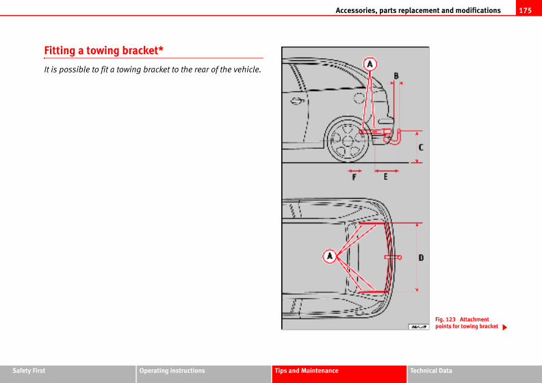
Accessories, parts replacement and modifications 175
Safety Fir Technical Data
Fig. 123 Attachment points for towing bracket
st Operating instructions Tips and Maintenance
Fitting a towing bracket*
It is possible to fit a towing bracket to the rear of the vehicle.
Accessories, parts replacement and modifications176
se observe the instructions provided by the racket.
correctly installed, this could cause damage to
.
RT, CUPRA...), fitting of a trailer bracket is not
ign of the bumpers.
If a towing bracket is to be fitted after the vehicle is purchased, this must be
completed according to the instructions of the towing bracket manufacturer.
The attachment points for the towing bracket are underneath the vehicle.
The distance between the centre of the ball coupling and the ground should
never be lower than the measurement indicated when the vehicle is fully
loaded including the maximum resting weight.
Measurement for securing the towing bracket:
65 mm (minimum)
from 350 mm to 420 mm (fully laden vehicle)
960 mm
345 mm
188 mm
Fitting a towing bracket
• Driving with a trailer implies additional work for the vehicle. Therefore,
before fitting a towing bracket, please contact an Authorised Service Centre
to check whether your cooling system needs modification.
• Observe the legal requirements in your country (e.g. the fitting of a sepa-
rate warning lamp).
• Certain vehicle components, e.g. the rear bumper must be removed and
reinstalled. The towing bracket securing bolts must be tightened using a
torque wrench, and an electrical socket must be used to connect to the
vehicle's electrical system. This requires specialist knowledge and tools.
• The figures in the illustration show the dimensions and attachment points
which must be observed if you are retrofitting a towing bracket.
WARNING
Towing brackets should be fitted by specialists.
• If the towing bracket is incorrectly installed, there is serious danger of an accident.
• For your own safety, pleamanufacturer of the towing b
Caution• If the electrical socket is in
the vehicle's electrical system
NoteFor the sports model (FR, SPO
recommended due to the des
AA
AB
AC
AD
AE
AF
WARNING (continued)
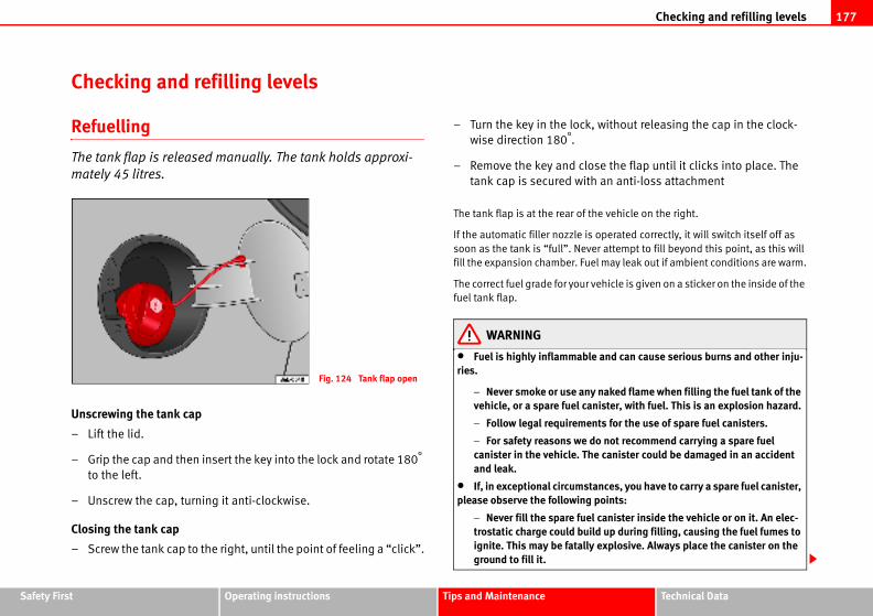
Checking and refilling levels 177
Safety Fir Technical Data
, without releasing the cap in the clock-
ose the flap until it clicks into place. The
th an anti-loss attachment
the vehicle on the right.
s operated correctly, it will switch itself off as
ver attempt to fill beyond this point, as this will
el may leak out if ambient conditions are warm.
r vehicle is given on a sticker on the inside of the
le and can cause serious burns and other inju-
y naked flame when filling the fuel tank of the anister, with fuel. This is an explosion hazard.
ents for the use of spare fuel canisters.
do not recommend carrying a spare fuel he canister could be damaged in an accident
tances, you have to carry a spare fuel canister, g points:
el canister inside the vehicle or on it. An elec-ild up during filling, causing the fuel fumes to
ly explosive. Always place the canister on the
st Operating instructions Tips and Maintenance
Checking and refilling levels
Refuelling
The tank flap is released manually. The tank holds approxi-
mately 45 litres.
Unscrewing the tank cap
– Lift the lid.
– Grip the cap and then insert the key into the lock and rotate 180°
to the left.
– Unscrew the cap, turning it anti-clockwise.
Closing the tank cap
– Screw the tank cap to the right, until the point of feeling a “click”.
– Turn the key in the lock
wise direction 180°.
– Remove the key and cl
tank cap is secured wi
The tank flap is at the rear of
If the automatic filler nozzle i
soon as the tank is “full”. Ne
fill the expansion chamber. Fu
The correct fuel grade for you
fuel tank flap.
WARNING
• Fuel is highly inflammabries.
− Never smoke or use anvehicle, or a spare fuel c
− Follow legal requirem
− For safety reasons wecanister in the vehicle. Tand leak.
• If, in exceptional circumsplease observe the followin
− Never fill the spare futrostatic charge could buignite. This may be fatalground to fill it.
Fig. 124 Tank flap open
Checking and refilling levels178
y the octane rating, e.g: 91, 95, 98 RON (RON
r, unit for determining the knock resistance of
ith a higher octane number than the one recom-
ever, this has no advantage in terms of fuel
er. If, in exceptional circumstances, the correct
Premium unleaded petrol (95 RON) the
eaded fuel with 91 RON can also be used. This
t loss of power under certain driving conditions.
Premium unleaded petrol (98 RON) the
leaded fuel with 95 RON can also be used. This
loss of power under certain driving conditions.
is not available, the engine can be run on
1 RON as an “emergency measure”. In this
e speeds and a light throttle. Avoid using full
petrol as soon as possible.
may be mixed with small quantities of ethanol.
hanol fuels” available at commercial establish-
5, which contain a high percentage of ethanol,
damage the fuel system.
d fuel would permanently impair the efficiency
ll throttle can damage the engine when using
wer than the correct grade for the engine.
vironmentel would seriously impair the efficiency of the
− Insert the fuel nozzle into the mouth of the canister as far as possible.
− If the spare fuel canister is made of metal, the filling nozzle must be in contact with the canister during filling. This helps prevent an electro-static charge building up.
− Never spill fuel in the vehicle or in the luggage compartment. Fuel vapours are explosive. Danger of death.
Caution• Fuel spills should be removed from the paintwork immediately.
• Never run the tank completely dry. An irregular fuel supply could cause
misfiring. As a result, unburnt fuel could enter the catalytic converter and
cause damage.
For the sake of the environmentDo not try to put in more fuel after the automatic filler nozzle has switched off;
this may cause the fuel to overflow if it becomes warm.
Petrol
Petrol types
The correct petrol types are listed on a sticker inside the fuel
tank flap.
Only unleaded petrol, corresponding to the standard DIN EN 228, may be
used for vehicles with catalytic converters (EN = “European Norm”).
Fuel types are differentiated b
= “Regulation Octane Numbe
petrol”). You may use petrol w
mended for your engine. How
consumption and engine pow
octane rating is not available:
• For engines which require
following is valid: Regular unl
can, however, result in a sligh
• For engines which require
following is valid: Premium un
can, however, result in a slight
– If premium unleaded petrol
regular unleaded petrol with 9
case only use moderate engin
throttle. Fill up with premium
Caution• Petrol that follows EN 228
However, the so-called “bioet
ments with reference E50 or E8
may not be used, as they will
• Even one tankfull of leade
of the catalytic converter.
• High engine speed and fu
petrol with an octane rating lo
For the sake of the enJust one full tank of leaded fu
catalytic converter.
WARNING (continued)
Checking and refilling levels 179
Safety Fir Technical Data
tion for “Deutsches Institut für Normung e.V.”,
te.
.
viation for “Fatty Acid Methyl Ester”
le includes the number PR 2G0 optional equip-
hicle has been prepared for biodiesel use.
re or automobile association will be able to
ain RME biodiesel fuel.
re can also be consulted to know if the vehicle
sel use.
el (biodiesel)
icle using biodiesel maybe somewhat reduced.
hicle using biodiesel may be slightly higher.
inter at temperatures down to approx. -10°C.
elow -10° C, we recommend using winter diesel
fuel system in vehicles which are not suitably
esel in your vehicle, please use only RME fuel
iant.
oes not meet the required standard, the fuel
peratures and a fuel biodiesel percentage of
in gas emission may occur during operation of
st Operating instructions Tips and Maintenance
Petrol additives
Petrol additives improve the quality of the petrol.
The quality of the petrol influences running behaviour, performance and
service life of the engine. For this reason you should use good quality petrol
containing additives. These additives will help to prevent corrosion, keep the
fuel system clean and prevent deposits from building up in the engine.
If good quality petrol with additives is not available or engine problems occur,
the required additives must be added during refuelling.
Diesel
Diesel*
Diesel fuel must correspond to DIN EN 590 (EN = “European standard”). It
must have a cetane number (CN) of at least 51. The cetane number indicates
the ignition quality of the diesel fuel.
Notes on filling with fuel ⇒ page 177.
RME fuel*
Only those vehicles fitted with special equipment (number PR
2G0 for biodiesel use) may use biodiesel corresponding to
the standard DIN EN 14214.
The biodiesel fuel must comply with the DIN EN 14.214 (FAME) Standard.
• Biodiesel is a methylester obtained from rapeseed oil.
• DIN is a German abbrevia
the German standards institu
• EN means European Norm
• FAME is the English abbre
If the date sticker of the vehic
ment) this means that that ve
Your Authorised Service Cent
advise on where you can obt
Your Authorised Service Cent
has been prepared for biodie
Things to note about RME fu
• The performance of a veh
• Fuel consumption of a ve
• RME fuel can be used in w
• At outside temperatures b
fuel.
Caution• RME fuel can damage the
adjusted.
• If you decide to use biodi
which is DIN E 14,214 compl
• If you use biodiesel that d
filter could become clogged.
Note• In case of low exterior tem
higher than 50%, an increase
the independent heating.
Checking and refilling levels180
inners”, or similar additives) with diesel fuel.
gine compartment
orking in the engine compartment
the engine compartment or on the
out cautiously.
n the engine or in the engine compart-
nd remove the key from the ignition.
eutral or the selector lever to position P.
ool down.
the vehicle.
ge 182.
the engine compartment unless you know
bs and have the correct tools! Have the work
shop if you are uncertain.
bles, e.g. coolant, engine oil, spark plugs and
y developed. SEAT provides a constant flow of
Service Centres concerning modifications. For
• The fuel filter may become clogged when fuel is changed to biodiesel. For
this reason, we recommend that, about every 300 or 400 km, following a fuel
change, also change the fuel filter. Also note the instructions in the Inspec-
tion and Maintenance plan.
• If the vehicle is to remain parked for more than about two weeks, we
recommend filling the fuel tank with biodiesel and driving about 50 km in
order to avoid damage to the injection system.
Winter driving
Diesel can thicken in winter.
Winter-grade diesel
When using “summer-grade diesel fuel”, difficulties may be experienced at
sub-zero temperatures because the fuel thickens due to wax separation. For
this reason, “winter-grade diesel fuel” is available in some countries during
the cold months. It can be used at temperatures as low as -22°C.
In countries with different climatic conditions the diesel fuel sold generally
has different temperature characteristics. Check with an Authorised Service
Centre or filling stations in the country concerned regarding the type of diesel
fuels available.
Filter pre-heater
Your vehicle is fitted with a fuel filter pre-heater, making it well equipped for
operation in winter. This ensures that the fuel system remains operational to
approx. -24°C, provided you use winter-grade diesel which is safe to -15°C.
However, if the fuel has waxed to such an extent that the engine will not start
at temperatures of under -24°C, simply place the vehicle in a warm place for
a while.
CautionDo not mix fuel additives (“th
Working in the en
Safety instructions on w
Any work carried out in
engine must be carried
Before starting any work o
ment:
1. Switch off the engine a
2. Apply the handbrake.
3. Move the gear stick to n
4. Wait for the engine to c
5. Keep children away from
6. Raise the bonnet ⇒ pa
You should not do any work in
exactly how to carry out the jo
carried out by a qualified work
All service fluids and consuma
batteries, are being constantl
information to the Authorised
Checking and refilling levels 181
Safety Fir Technical Data
ve not left any objects, such as cleaning cloths partment.
rneath the vehicle, you must use suitable ort the vehicle, there is a risk of accident!. A for securing the vehicle and there is a risk of
formed when the engine is started or with the dditional, potentially fatal, safety risk from the rive belts, alternator, radiator fan, etc., and
on system. You should also observe the
rical wiring of the ignition system.
loose clothing and long hair do not get e parts. Danger of death. Before starting any
ie back and cover hair, and wear tight-fitting
about pressing the accelerator if a gear is omatic or manual gearbox. The vehicle could rake is applied. Danger of death.
out on the fuel system or on electrical compo- following safety notes in addition to the above
e battery. The vehicle must be unlocked when he alarm will be triggered.
d flames.
inguisher on hand.
st Operating instructions Tips and Maintenance
this reason we recommend that you have service fluids and consumables
replaced by an Authorised Service Centre. Please observe the relevant
instructions ⇒ page 172. The engine compartment of any motor vehicle is a
hazardous area ⇒ .
WARNING
All work on the engine or in the engine compartment, e.g. checking and refilling fluids, involves the danger of injury and scalding as well as the risk of accident or fire.
• Never open the bonnet if you see steam, smoke or coolant escaping from the engine compartment. Otherwise, there is a risk of sustaining burns. Wait until no more steam or coolant is emitted, then allow the engine to cool before carefully opening the bonnet.
• Switch off the engine and remove the key from the ignition.
• Apply the handbrake and move the gear stick to neutral or selector lever to position P.
• Keep children away from the vehicle.
• Never touch hot engine parts. There is a risk of burns.
• Never spill liquids on a hot engine or on a hot exhaust gas system. This is a fire hazard.
• Avoid causing short-circuits in the electrical system, particularly at the points where the jump leads are attached ⇒ page 231. The battery could explode.
• Never touch the radiator fan. It is temperature controlled and could start automatically, even when the engine has been switched off and the key removed from the ignition!
• Do not unscrew the cap on the expansion tank when the engine is hot. If the coolant is hot, the cooling system will be pressurised!
• Protect face, hands and arms by covering the cap with a large, thick cloth to protect against escaping coolant and steam.
• Always make sure you haand tools, in the engine com
• If you have to work undestands additionally to supphydraulic jack is insufficientinjury.
• If any work has to be perengine running, there is an arotating parts, such as the dfrom the high-voltage ignitifollowing points:
− Never touch the elect
− Ensure that jewellery,trapped in rotating enginwork remove jewellery, tclothes.
− Always think carefullyengaged in either an autmove, even if the handb
• If work has to be carriednents, you must observe thewarnings:
− Always disconnect ththis is done, otherwise t
− Do not smoke.
− Never work near nake
− Always have a fire ext
WARNING (continued)
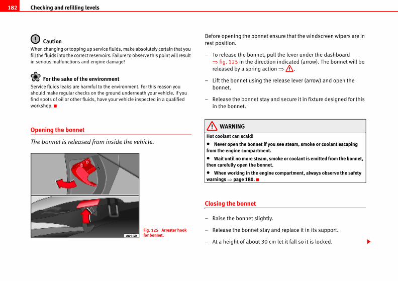
Checking and refilling levels182
ensure that the windscreen wipers are in
pull the lever under the dashboard
ion indicated (arrow). The bonnet will be
tion ⇒ .
e release lever (arrow) and open the
y and secure it in fixture designed for this
you see steam, smoke or coolant escaping t.
smoke or coolant is emitted from the bonnet, et.
ine compartment, always observe the safety
ly.
y and replace it in its support.
cm let it fall so it is locked.
CautionWhen changing or topping up service fluids, make absolutely certain that you
fill the fluids into the correct reservoirs. Failure to observe this point will result
in serious malfunctions and engine damage!
For the sake of the environmentService fluids leaks are harmful to the environment. For this reason you
should make regular checks on the ground underneath your vehicle. If you
find spots of oil or other fluids, have your vehicle inspected in a qualified
workshop.
Opening the bonnet
The bonnet is released from inside the vehicle.
Before opening the bonnet
rest position.
– To release the bonnet,
⇒ fig. 125 in the direct
released by a spring ac
– Lift the bonnet using th
bonnet.
– Release the bonnet sta
in the bonnet.
WARNING
Hot coolant can scald!
• Never open the bonnet if from the engine compartmen
• Wait until no more steam,then carefully open the bonn
• When working in the engwarnings ⇒ page 180.
Closing the bonnet
– Raise the bonnet slight
– Release the bonnet sta
– At a height of about 30
Fig. 125 Arrester hook for bonnet.
Checking and refilling levels 183
Safety Fir Technical Data
s on the performance of the engine for example,
consumption and a higher emission level.
fferent oils may be mixed as long as they all
.
ards) set out in the following page should
e service oil; the container will display together
trol and diesel engines, the oil can be used for
st Operating instructions Tips and Maintenance
If the bonnet does not close, do not press downwards. Open it once more and
let it fall as before.
WARNING
If the bonnet is not closed properly, it could open while you are driving and completely obscure your view of the road. Risk of accident.
• After closing the bonnet, always check that it is properly secured. The bonnet must be flush with the surrounding body panels.
• If you notice that the bonnet latch is not secured when the vehicle is moving, stop the vehicle immediately and close the bonnet properly. Risk of accident.
Engine oil
Engine oil specifications
The engine oil used must conform with exact specifications.
Specifications
The engine comes with a special, high quality, multi grade oil that can be
used in all seasons of the year except for those regions affected by extreme
cold.
As the use of good quality oil is necessary for the correct operation and long
service life of the engine, when it becomes necessary to replenish or change
the oil, always use an oil that complies to the VW standards.
If it is not possible to find oil conforming to the VW standards then oil
conforming to the ACEA or API standards with an appropriate viscosity at
atmospheric temperature should be used instead. The use of this type of oil
may have some repercussion
long starting time, increased
If a top up is required then di
conform to the VW standards
The specifications (VW stand
appear on the container of th
the different standards for pe
both types of engines.
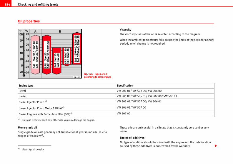
Checking and refilling levels184
selected according to the diagram.
e falls outside the limits of the scale for a short
quired.
climate that is constantly very cold or very
mixed with the engine oil. The deterioration
ot covered by the warranty.
00
00/ VW 506 01
01
Oil properties
Viscosity
The viscosity class of the oil is
When the ambient temperatur
period, an oil change is not re
Mono-grade oil
Single grade oils are generally not suitable for all year round use, due to
ranges of viscosity6).
These oils are only useful in a
warm.
Engine oil additives
No type of additive should be
caused by these additives is n
Fig. 126 Types of oil according to temperature
Engine type Specification
Petrol VW 501 01/ VW 502 00/ VW 504
Diesel VW 505 00/ VW 505 01/ VW 507
Diesel Injector Pump a)
a) Only use recommended oils, otherwise you may damage the engine.
VW 505 01/ VW 507 00/ VW 506
Diesel Injector Pump Motor 118 kWa) VW 506 01/ VW 507 00
Diesel Engines with Particulate filter (DPF)a) VW 507 00
6) Viscosity: oil density
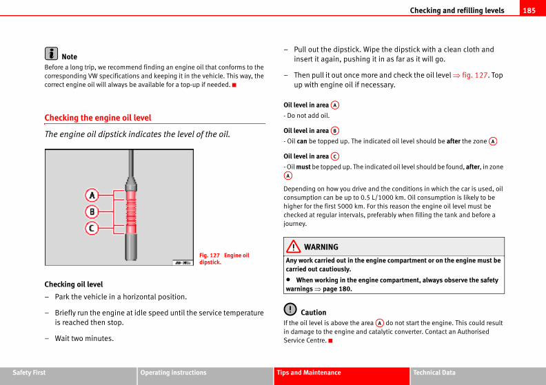
Checking and refilling levels 185
Safety Fir Technical Data
ipe the dipstick with a clean cloth and
g it in as far as it will go.
ore and check the oil level ⇒ fig. 127. Top
cessary.
dicated oil level should be after the zone
ndicated oil level should be found, after, in zone
and the conditions in which the car is used, oil
5 L/1000 km. Oil consumption is likely to be
For this reason the engine oil level must be
preferably when filling the tank and before a
engine compartment or on the engine must be
ine compartment, always observe the safety
ea do not start the engine. This could result
catalytic converter. Contact an Authorised
AA
AA
st Operating instructions Tips and Maintenance
NoteBefore a long trip, we recommend finding an engine oil that conforms to the
corresponding VW specifications and keeping it in the vehicle. This way, the
correct engine oil will always be available for a top-up if needed.
Checking the engine oil level
The engine oil dipstick indicates the level of the oil.
Checking oil level
– Park the vehicle in a horizontal position.
– Briefly run the engine at idle speed until the service temperature
is reached then stop.
– Wait two minutes.
– Pull out the dipstick. W
insert it again, pushin
– Then pull it out once m
up with engine oil if ne
Oil level in area
- Do not add oil.
Oil level in area
- Oil can be topped up. The in
Oil level in area
- Oil must be topped up. The i
Depending on how you drive
consumption can be up to 0.
higher for the first 5000 km.
checked at regular intervals,
journey.
WARNING
Any work carried out in the carried out cautiously.
• When working in the engwarnings ⇒ page 180.
CautionIf the oil level is above the ar
in damage to the engine and
Service Centre.
Fig. 127 Engine oil dipstick.
AA
AB
AC
AA
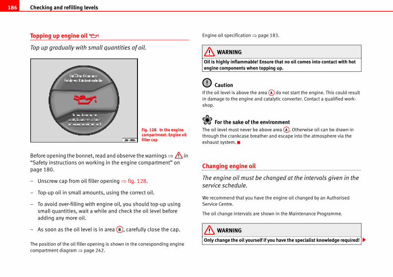
Checking and refilling levels186
ge 183.
sure that no oil comes into contact with hot pping up.
a do not start the engine. This could result
catalytic converter. Contact a qualified work-
vironmentove area . Otherwise oil can be drawn in
er and escape into the atmosphere via the
hanged at the intervals given in the
the engine oil changed by an Authorised
own in the Maintenance Programme.
if you have the specialist knowledge required!
AA
AA
Topping up engine oil
Top up gradually with small quantities of oil.
Before opening the bonnet, read and observe the warnings ⇒ in
“Safety instructions on working in the engine compartment” on
page 180.
– Unscrew cap from oil filler opening ⇒ fig. 128.
– Top-up oil in small amounts, using the correct oil.
– To avoid over-filling with engine oil, you should top-up using
small quantities, wait a while and check the oil level before
adding any more oil.
– As soon as the oil level is in area , carefully close the cap.
The position of the oil filler opening is shown in the corresponding engine
compartment diagram ⇒ page 242.
Engine oil specification ⇒ pa
WARNING
Oil is highly inflammable! Enengine components when to
CautionIf the oil level is above the are
in damage to the engine and
shop.
For the sake of the enThe oil level must never be ab
through the crankcase breath
exhaust system.
Changing engine oil
The engine oil must be c
service schedule.
We recommend that you have
Service Centre.
The oil change intervals are sh
WARNING
Only change the oil yourself
Fig. 128 In the engine compartment: Engine oil filler cap
AB
Checking and refilling levels 187
Safety Fir Technical Data
water and at least 40% coolant addi-
illed with a mixture of water and at least 40 % of
an additive with the specification TT-VW 774 F
re gives the necessary frost protection down to
arts of the cooling system against corrosion. It
ses the boiling point of the coolant.
must always be at least 40% - even if frost
equired in very cold climates, the proportion of
can be increased. However, the percentage of
exceed 60%, as this would reduce the frost
ce the cooling effect. A mixture with 60%
t protection to approx. -40°C.
oxic. There is a toxic risk. Always keep the al container which should be stored out of the
applies to coolant which you have drained off.
2+ must be added in sufficient quantities to n at the coldest ambient temperatures that ly cold ambient temperatures, the coolant hicle to breakdown. As the heater would also ere is a risk of suffering exposure!
st Operating instructions Tips and Maintenance
• Before opening the bonnet, read and observe the warnings ⇒ page 180, “Safety instructions on working in the engine compartment”.
• Wait for the engine to cool down. Hot oil may cause burn injuries.
• Wear eye protection to avoid injuries caused by splashes of oil.
• When removing the oil drain plug with your fingers, keep your arm hori-zontal to help prevent oil from running down your arm.
• Wash your skin thoroughly if it comes into contact with engine oil.
• Engine oil is poisonous! Used oil must be stored in a safe place out of the reach of children until it is disposed of.
CautionNo additives should be used with engine oil. This could result in engine
damage. Any damage caused by the use of such additives would not be
covered by the factory warranty.
For the sake of the environment• Because of the disposal problems, the necessary special tools and
specialist knowledge required, we recommend that you have the engine oil
and filter changed by an Authorised Service Centre.
• Never pour oil down drains or into the ground.
• Use a suitable container when draining the used oil. It has to be large
enough to hold all the engine oil.
Coolant
Coolant specifications
Coolant is a mixture of
tive.
The cooling system must be f
our coolant additive G 12+ or
(it is dyed purple). This mixtu
-25°C and protects the alloy p
also prevents scaling and rai
The concentration of coolant
protection is not required.
If greater frost protection is r
the antifreeze additive G 12+
coolant additives should not
protection. It would also redu
coolant additive will give fros
WARNING
• The coolant additive is tcoolant additive in the originreach of children. The same
• The coolant additive G 1provide anti-freeze protectiocan be expected. At extremecould freeze, causing the venot work in this situation, th
WARNING (continued)
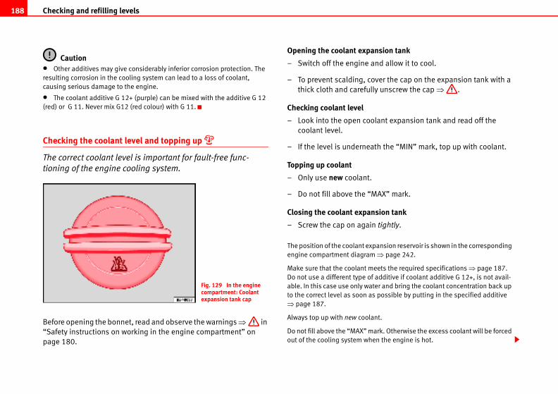
Checking and refilling levels188
nsion tank
nd allow it to cool.
ver the cap on the expansion tank with a
y unscrew the cap ⇒ .
lant expansion tank and read off the
th the “MIN” mark, top up with coolant.
AX” mark.
sion tank
tightly.
ansion reservoir is shown in the corresponding
⇒ page 242.
ets the required specifications ⇒ page 187.
additive if coolant additive G 12+, is not avail-
er and bring the coolant concentration back up
possible by putting in the specified additive
nt.
rk. Otherwise the excess coolant will be forced
n the engine is hot.
Caution• Other additives may give considerably inferior corrosion protection. The
resulting corrosion in the cooling system can lead to a loss of coolant,
causing serious damage to the engine.
• The coolant additive G 12+ (purple) can be mixed with the additive G 12
(red) or G 11. Never mix G12 (red colour) with G 11.
Checking the coolant level and topping up
The correct coolant level is important for fault-free func-
tioning of the engine cooling system.
Before opening the bonnet, read and observe the warnings ⇒ in
“Safety instructions on working in the engine compartment” on
page 180.
Opening the coolant expa
– Switch off the engine a
– To prevent scalding, co
thick cloth and carefull
Checking coolant level
– Look into the open coo
coolant level.
– If the level is undernea
Topping up coolant
– Only use new coolant.
– Do not fill above the “M
Closing the coolant expan
– Screw the cap on again
The position of the coolant exp
engine compartment diagram
Make sure that the coolant me
Do not use a different type of
able. In this case use only wat
to the correct level as soon as
⇒ page 187.
Always top up with new coola
Do not fill above the “MAX” ma
out of the cooling system whe
Fig. 129 In the engine compartment: Coolant expansion tank cap
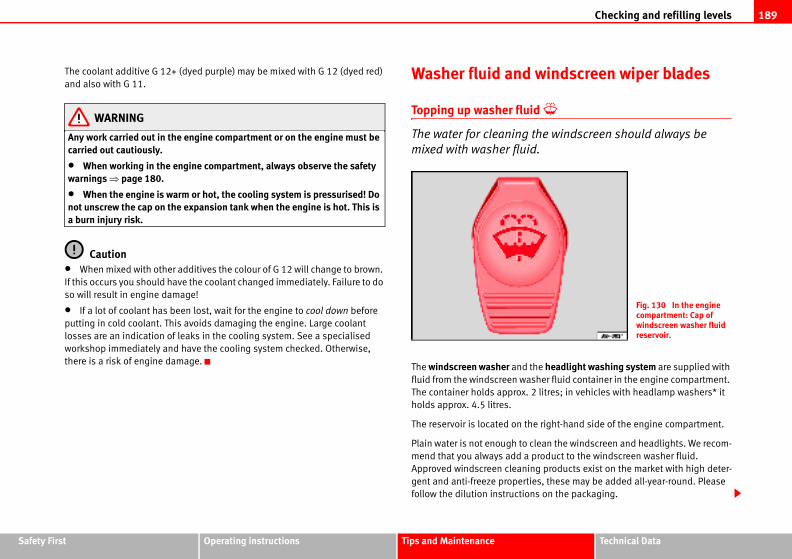
Checking and refilling levels 189
Safety Fir Technical Data
windscreen wiper blades
d
the windscreen should always be
.
he headlight washing system are supplied with
sher fluid container in the engine compartment.
2 litres; in vehicles with headlamp washers* it
e right-hand side of the engine compartment.
lean the windscreen and headlights. We recom-
product to the windscreen washer fluid.
g products exist on the market with high deter-
es, these may be added all-year-round. Please
s on the packaging.
Fig. 130 In the engine compartment: Cap of windscreen washer fluid reservoir.
st Operating instructions Tips and Maintenance
The coolant additive G 12+ (dyed purple) may be mixed with G 12 (dyed red)
and also with G 11.
WARNING
Any work carried out in the engine compartment or on the engine must be carried out cautiously.
• When working in the engine compartment, always observe the safety warnings ⇒ page 180.
• When the engine is warm or hot, the cooling system is pressurised! Do not unscrew the cap on the expansion tank when the engine is hot. This is a burn injury risk.
Caution• When mixed with other additives the colour of G 12 will change to brown.
If this occurs you should have the coolant changed immediately. Failure to do
so will result in engine damage!
• If a lot of coolant has been lost, wait for the engine to cool down before
putting in cold coolant. This avoids damaging the engine. Large coolant
losses are an indication of leaks in the cooling system. See a specialised
workshop immediately and have the cooling system checked. Otherwise,
there is a risk of engine damage.
Washer fluid and
Topping up washer flui
The water for cleaning
mixed with washer fluid
The windscreen washer and t
fluid from the windscreen wa
The container holds approx.
holds approx. 4.5 litres.
The reservoir is located on th
Plain water is not enough to c
mend that you always add a
Approved windscreen cleanin
gent and anti-freeze properti
follow the dilution instruction
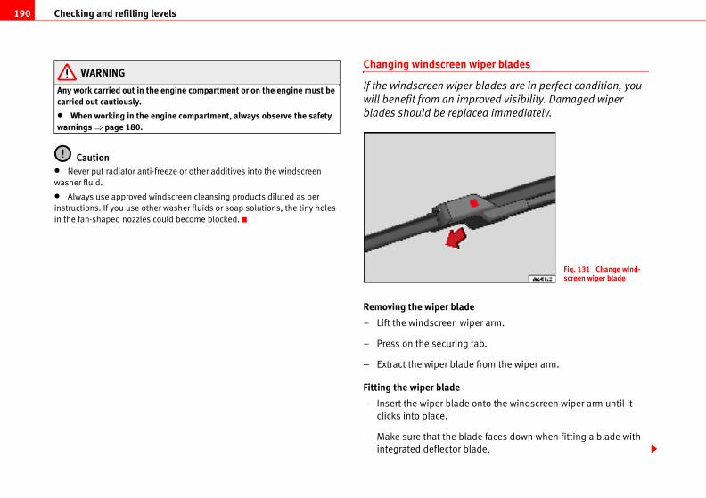
Checking and refilling levels190
iper blades
blades are in perfect condition, you
roved visibility. Damaged wiper
ed immediately.
er arm.
ab.
from the wiper arm.
nto the windscreen wiper arm until it
e faces down when fitting a blade with
de.
Fig. 131 Change wind-screen wiper blade
WARNING
Any work carried out in the engine compartment or on the engine must be carried out cautiously.
• When working in the engine compartment, always observe the safety warnings ⇒ page 180.
Caution• Never put radiator anti-freeze or other additives into the windscreen
washer fluid.
• Always use approved windscreen cleansing products diluted as per
instructions. If you use other washer fluids or soap solutions, the tiny holes
in the fan-shaped nozzles could become blocked.
Changing windscreen w
If the windscreen wiper
will benefit from an imp
blades should be replac
Removing the wiper blade
– Lift the windscreen wip
– Press on the securing t
– Extract the wiper blade
Fitting the wiper blade
– Insert the wiper blade o
clicks into place.
– Make sure that the blad
integrated deflector bla
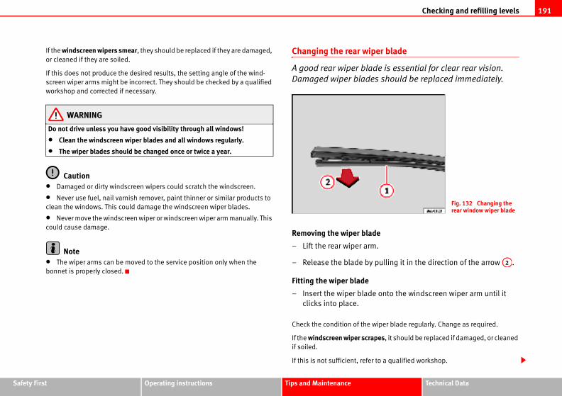
Checking and refilling levels 191
Safety Fir Technical Data
r blade
e is essential for clear rear vision.
should be replaced immediately.
ulling it in the direction of the arrow .
onto the windscreen wiper arm until it
iper blade regularly. Change as required.
es, it should be replaced if damaged, or cleaned
o a qualified workshop.
Fig. 132 Changing the rear window wiper blade
A2
st Operating instructions Tips and Maintenance
If the windscreen wipers smear, they should be replaced if they are damaged,
or cleaned if they are soiled.
If this does not produce the desired results, the setting angle of the wind-
screen wiper arms might be incorrect. They should be checked by a qualified
workshop and corrected if necessary.
WARNING
Do not drive unless you have good visibility through all windows!
• Clean the windscreen wiper blades and all windows regularly.
• The wiper blades should be changed once or twice a year.
Caution• Damaged or dirty windscreen wipers could scratch the windscreen.
• Never use fuel, nail varnish remover, paint thinner or similar products to
clean the windows. This could damage the windscreen wiper blades.
• Never move the windscreen wiper or windscreen wiper arm manually. This
could cause damage.
Note• The wiper arms can be moved to the service position only when the
bonnet is properly closed.
Changing the rear wipe
A good rear wiper blad
Damaged wiper blades
Removing the wiper blade
– Lift the rear wiper arm.
– Release the blade by p
Fitting the wiper blade
– Insert the wiper blade
clicks into place.
Check the condition of the w
If the windscreen wiper scrapif soiled.
If this is not sufficient, refer t
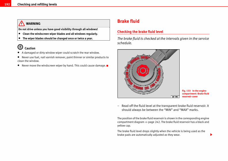
Checking and refilling levels192
d level
d at the intervals given in the service
at the transparent brake fluid reservoir. It
een the “MIN” and “MAX” marks.
reservoir is shown in the corresponding engine
e 242. The brake fluid reservoir has a black and
ghtly when the vehicle is being used as the
adjusted as they wear.
Fig. 133 In the engine compartment: Brake fluid reservoir cover
WARNING
Do not drive unless you have good visibility through all windows!
• Clean the windscreen wiper blades and all windows regularly.
• The wiper blades should be changed once or twice a year.
Caution• A damaged or dirty window wiper could scratch the rear window.
• Never use fuel, nail varnish remover, paint thinner or similar products to
clean the window.
• Never move the windscreen wiper by hand. This could cause damage.
Brake fluid
Checking the brake flui
The brake fluid is checke
schedule.
– Read off the fluid level
should always be betw
The position of the brake fluid
compartment diagram ⇒ pag
yellow cap.
The brake fluid level drops sli
brake pads are automatically
Checking and refilling levels 193
Safety Fir Technical Data
et to check the brake fluid level, read and ge 180.
red in the closed original container in a safe n. There is a toxic risk.
change according to the Maintenance rakes may cause a vapour lock if the brake fluid ong. This would seriously affect the efficiency of the vehicle. This may cause an accident.
paintwork. Wipe off any brake fluid from the
nvironmentnd disposed of in the proper manner observing
st Operating instructions Tips and Maintenance
However, if the level goes down noticeably in a short time, or drops below the
“MIN” mark, there may be a leak in the brake system. A display on the instru-
ment panel will warn you if the brake fluid level is too low ⇒ page 60.
WARNING
Before opening the bonnet to check the brake fluid level, read and observe the warnings ⇒ page 180.
Changing the brake fluid
The Maintenance Program indicates the brake fluid change
intervals.
We recommend that you have the brake fluid changed by an Authorised
Service Centre.
Before opening the bonnet, please read and follow the warnings ⇒ in
“Safety instructions on working in the engine compartment” on page 180 in
“Working in the engine compartment”.
Brake fluid absorbs moisture. In the course of time, it will absorb water from
the ambient air. If the water content in the brake fluid is too high, the brake
system could corrode. This also considerably reduces the boiling point of the
brake fluid. Heavy use of the brakes may then cause a vapour lock which
could impair the braking effect.
It is important that you use only brake fluid compliant with the US standard
FMVSS 116 DOT 4. We recommend the use of Genuine SEAT brake fluid.
WARNING
Brake fluid is poisonous. Old brake fluid impairs the braking effect.
• Before opening the bonnobserve the warnings ⇒ pa
• Brake fluid should be stoplace out of reach of childre
• Complete the brake fluidProgram. Heavy use of the bis left in the system for too lof the brakes and the safety
CautionBrake fluid could damage the
paintwork immediately.
For the sake of the eBrake fluid must be drained a
environmental regulations.
WARNING (continued)
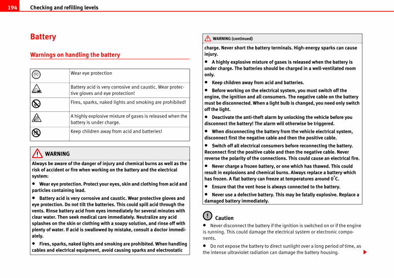
Checking and refilling levels194
ry terminals. High-energy sparks can cause
e of gases is released when the battery is hould be charged in a well-ventilated room
acid and batteries.
ctrical system, you must switch off the onsumers. The negative cable on the battery a light bulb is changed, you need only switch
alarm by unlocking the vehicle before you larm will otherwise be triggered.
battery from the vehicle electrical system, cable and then the positive cable.
nsumers before reconnecting the battery. able and then the negative cable. Never nnections. This could cause an electrical fire.
tery, or one which has thawed. This could ical burns. Always replace a battery which
freeze at temperatures around 0°C.
is always connected to the battery.
tery. This may be fatally explosive. Replace a y.
ry if the ignition is switched on or if the engine
the electrical system or electronic compo-
to direct sunlight over a long period of time, as
n can damage the battery housing.
Battery
Warnings on handling the battery
WARNING
Always be aware of the danger of injury and chemical burns as well as the risk of accident or fire when working on the battery and the electrical system:
• Wear eye protection. Protect your eyes, skin and clothing from acid and particles containing lead.
• Battery acid is very corrosive and caustic. Wear protective gloves and eye protection. Do not tilt the batteries. This could spill acid through the vents. Rinse battery acid from eyes immediately for several minutes with clear water. Then seek medical care immediately. Neutralize any acid splashes on the skin or clothing with a soapy solution, and rinse off with plenty of water. If acid is swallowed by mistake, consult a doctor immedi-ately.
• Fires, sparks, naked lights and smoking are prohibited. When handling cables and electrical equipment, avoid causing sparks and electrostatic
charge. Never short the batteinjury.
• A highly explosive mixturunder charge. The batteries sonly.
• Keep children away from
• Before working on the eleengine, the ignition and all cmust be disconnected. Whenoff the light.
• Deactivate the anti-theft disconnect the battery! The a
• When disconnecting the disconnect first the negative
• Switch off all electrical coReconnect first the positive creverse the polarity of the co
• Never charge a frozen batresult in explosions and chemhas frozen. A flat battery can
• Ensure that the vent hose
• Never use a defective batdamaged battery immediatel
Caution• Never disconnect the batte
is running. This could damage
nents.
• Do not expose the battery
the intense ultraviolet radiatio
Wear eye protection
Battery acid is very corrosive and caustic. Wear protec-
tive gloves and eye protection!
Fires, sparks, naked lights and smoking are prohibited!
A highly explosive mixture of gases is released when the
battery is under charge.
Keep children away from acid and batteries!
WARNING (continued)
Checking and refilling levels 195
Safety Fir Technical Data
the vehicle battery
nce-free and is checked during the
ork on the vehicle battery requires
ces or if the vehicle is not driven for long
e checked by a qualified workshop between the
and you have problems starting the vehicle, the
this happens, we recommend you have the
Authorised Service Centre where it will be re-
charged by a qualified workshop only, as
ology have been installed and they must be
onment.
ed to suit the conditions of its location and has
the maintenance, performance and safety spec-
only maintenance-free or cycle free leak-proof the standards T 825 06 and VW 7 50 73. This .
on the batteries, you must read and observe nings on handling the battery” on page 194.
st Operating instructions Tips and Maintenance
• If the vehicle is left standing in cold conditions for a long period, protect
the battery from frost. If it “freezes” it will be damaged.
Checking the electrolyte level
The electrolyte level should be checked regularly in high-
mileage vehicles, in hot countries and in older batteries.
– Open the bonnet and open the battery cover at the front ⇒ in
“Safety instructions on working in the engine compartment” on
page 180 ⇒ in “Warnings on handling the battery” on
page 194.
– Check the colour display in the "magic eye" on the top of the
battery.
– If there are air bubbles in the window, tap the window gently until
they disperse.
The position of the battery is shown in the corresponding engine compart-
ment diagram ⇒ page 242.
The round window (“magic eye”) on the top of the battery changes colour,
depending on the charge level and electrolyte level of the battery.
If the colour in the window is colourless or bright yellow, the electrolyte level
of the battery is too low. Have the battery checked by a qualified workshop.
The colours green and black are used by the workshops for diagnostic
purposes.
Charging and changing
The battery is maintena
inspection service. All w
specialist knowledge.
If you often drive short distan
periods, the battery should b
scheduled services.
If the battery has discharged
battery might be damaged. If
vehicle battery checked by an
charged or replaced.
Charging the battery
The vehicle battery should be
batteries using special techn
charged in a controlled envir
Replacing a vehicle battery
The battery has been develop
special safety features.
Genuine SEAT batteries fulfil
ifications of your vehicle.
WARNING
• We recommend you use batteries which comply withstandard applies as of 2001
• Before starting any workthe warnings ⇒ in “War
Checking and refilling levels196
page 151.
ay vary, according to the type and make of tyre
ften not readily visible. If you notice unusual
one side, this may indicate that one of the tyres
be checked immediately by an Authorised
attern
ndicates the direction of rotation on tyres with
rve the direction of rotation indicated when
ees optimum grip and helps to avoid aqua-
wear.
ximum grip in the first 500 km. Drive particu-f accident.
d tyres. This may cause an accident.
ation or if the vehicle pulls to one side when ediately and check the tyres for damage.
For the sake of the environmentBatteries contain toxic substances such as sulphuric acid and lead. They
must be disposed of appropriately and must not be disposed of with ordinary
household waste.
Wheels
General notes
Avoiding damage
– If you have to drive over a kerb or similar obstacle, drive very
slowly and as near as possible at a right angle to the kerb.
– Keep grease, oil and fuel off the tyres.
– Inspect the tyres regularly for damage (cuts, cracks or blisters,
etc.). Remove any foreign objects embedded in the treads.
Storing tyres
– Mark tyres when you remove them to indicate the direction of
rotation. This ensures you will be able to install them correctly
when you replace them.
– When removed, the wheels and/or tyres should be stored in a
cool, dry and preferably dark location.
– Store tyres in a vertical position if they are not fitted on wheel
rims.
New tyres
New tyres have to be run in ⇒
The tread depth of new tyres m
and the tread pattern.
Concealed damage
Damage to tyres and rims is o
vibrations or the car pulling to
is damaged. The tyres should
Service Centre.
Tyres with directional tread p
An arrow on the tyre sidewall i
directional tread. Always obse
fitting the wheel. This guarant
planing, excessive noise and
WARNING
• New tyres do not have malarly carefully to avoid risk o
• Never drive with damage
• If you notice unusual vibrdriving, stop the vehicle imm
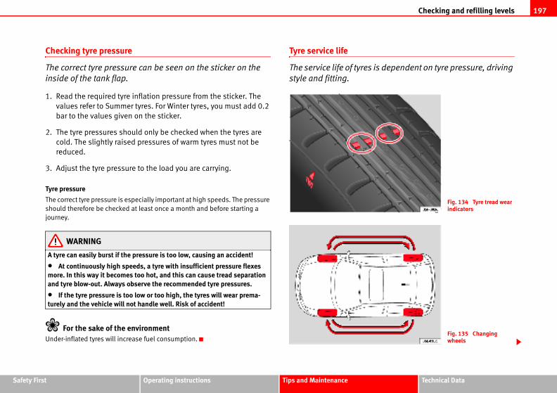
Checking and refilling levels 197
Safety Fir Technical Data
is dependent on tyre pressure, driving
Fig. 134 Tyre tread wear indicators
Fig. 135 Changing wheels
st Operating instructions Tips and Maintenance
Checking tyre pressure
The correct tyre pressure can be seen on the sticker on the
inside of the tank flap.
1. Read the required tyre inflation pressure from the sticker. The
values refer to Summer tyres. For Winter tyres, you must add 0.2
bar to the values given on the sticker.
2. The tyre pressures should only be checked when the tyres are
cold. The slightly raised pressures of warm tyres must not be
reduced.
3. Adjust the tyre pressure to the load you are carrying.
Tyre pressure
The correct tyre pressure is especially important at high speeds. The pressure
should therefore be checked at least once a month and before starting a
journey.
WARNING
A tyre can easily burst if the pressure is too low, causing an accident!
• At continuously high speeds, a tyre with insufficient pressure flexes more. In this way it becomes too hot, and this can cause tread separation and tyre blow-out. Always observe the recommended tyre pressures.
• If the tyre pressure is too low or too high, the tyres will wear prema-turely and the vehicle will not handle well. Risk of accident!
For the sake of the environmentUnder-inflated tyres will increase fuel consumption.
Tyre service life
The service life of tyres
style and fitting.
Checking and refilling levels198
ccidents if a tyre bursts during driving!
d at the latest when the tread is worn down to lure to do so could result in an accident. Worn speeds on wet roads. There is also a greater
eds, a tyre with insufficient pressure flexes eat. This can cause tread separation and tyre lways observe the recommended tyre pres-
ar, you should have the running gear checked tre.
il, fuel and brake fluid away from tyres.
s must be replaced immediately!
vironmentse fuel consumption.
ave to be run-in.
n essential part of the vehicle's design. The
AT are specially matched to the characteristics
jor contribution to good road holding and safe
ast in pairs and not individually (i.e. both front
er). A knowledge of tyre designations makes it
Wear indicators
The original tyres on your vehicle have 1.6 mm high “tread wear indicators”
⇒ page 197, fig. 134, running across the tread. Depending on the make,
there will be six to eight of them evenly spaced around the tyre. Markings on
the tyre sidewall (for instance the letters “TWI” or other symbols) indicate the
positions of the tread wear indicators. The minimum tread depth required by
law is 1.6 mm (measured in the tread grooves next to the tread wear indica-
tors). Worn tyres must be replaced. Different figures may apply in export
countries ⇒ .
Tyre pressure
Incorrect tyre pressure causes premature wear and could cause tyre blow-out.
For this reason, the tyre pressure should be checked at least once per month
⇒ page 197.
Driving style
Fast cornering, heavy acceleration and hard braking all increase tyre wear.
Changing wheels around
If the front tyres are worn considerably more than the rear ones it is advisable
to change them around as shown ⇒ page 197, fig. 135. All the tyres will then
last for about the same time.
Wheel balance
The wheels on new vehicles are balanced. However, various factors encoun-
tered in normal driving can cause them to become unbalanced, which results
in steering vibration.
Unbalanced wheels should be rebalanced, as they otherwise cause excessive
wear on steering, suspension and tyres. A wheel must also be rebalanced
when a new tyre is fitted.
Incorrect wheel alignment
Incorrect wheel alignment causes excessive tyre wear, impairing the safety of
the vehicle. If tyres show excessive wear, you should have the wheel align-
ment checked by an Authorised Service Centre.
WARNING
There is a serious danger of a
• The tyres must be replacethe tread wear indicators. Faityres do not grip well at highrisk of “aquaplaning”.
• At continuously high spemore. This causes it to overhblow-out. Risk of accident. Asures.
• If tyres show excessive weby an Authorised Service Cen
• Keep chemicals such as o
• Damaged wheels and tyre
For the sake of the enUnder-inflated tyres will increa
New tyres and wheels
New tyres and wheels h
The tyres and wheel rims are a
tyres and rims approved by SE
of the vehicle and make a ma
handling ⇒ .
Tyres should be replaced at le
tyres or both rear tyres togeth
Checking and refilling levels 199
Safety Fir Technical Data
e on tyres that are more than six years old. If should drive slowly and with extra care at all
ose with an unknown “history of use”.
ted, you must ensure that the flow of air to the s could cause them to overheat.
fitted with radial tyres of the same type, size he same tread pattern.
nvironmentf according to the laws in the country concerned.
s not generally possible to use the wheels from
apply to wheels of the same model. The use of
ot been approved by SEAT for use with your
icle's type approval for use on public roads.
same as the tyres that are mounted on the
ter tyres - you should only use the spare tyre for
ive with extra care. Refit the normal road wheel
htened to the correct torque.
matched to the rims. If different wheel rims are
with the right length and correctly shaped bolt
st Operating instructions Tips and Maintenance
easier to choose the correct tyres. Radial tyres have the tyre designations
marked on the sidewall, for example:
195/65 R15 91T
This contains the following information:
195 Tyre width in mm
65 Height/width ratio in %
R Tyre construction: Radial
15 Rim diameter in inches
91 Load rating code
T Speed rating
The tyres could also have the following information:
• A direction of rotation symbol
• “Reinforced” denotes heavy-duty tyres.
The manufacturing date is also indicated on the tyre sidewall (possibly only
on the inner side of the wheel).
“DOT... 1103...” means, for example, that the tyre was produced in the 11th
week of 2003.
We recommend that work on tyres and wheels is carried out by an Authorised
Service Centre. They are familiar with the procedure and have the necessary
special tools and spare parts as well as the proper facilities for disposing of
the old tyres.
Any Authorised Service Centre has full information on the technical require-
ments when installing or changing tyres, wheels or wheel trims.
WARNING
• We recommend that you use only wheels and tyres which have been approved by SEAT for your model. Failure to do so could impair vehicle handling. Risk of accident.
• Avoid running the vehiclyou have no alternative, youtimes.
• Never use old tyres or th
• If wheel trims are retrofitbrakes is not restricted. Thi
• All four wheels must be (rolling circumference) and t
For the sake of the eOld tyres must be disposed o
Note• For technical reasons, it i
other vehicles. This can also
wheels or tyres which have n
model may invalidate the veh
• If the spare tyre is not the
vehicle - for example with win
a short period of time and dr
as soon as possible.
Wheel bolts
Wheel bolts must be tig
The design of wheel bolts is
fitted, the correct wheel bolts
WARNING (continued)
Checking and refilling levels200
er tyre sizes can be found in the vehicle's regis-
adial winter tyres. All tyre sizes listed in the
pply to winter tyres.
eness when the tread is worn down to a depth
e 198, “New tyres and wheels” determines the
hich can exceed the speed rating of the fitted
sticker in the driver's field of view. These
r Authorised Service Centre. The legal require-
e followed.
for unnecessarily long periods. Vehicles with
hen the roads are free of snow and ice.
efer to the notes on the spare wheel
wheels”.
inter tyres must not be exceeded. Otherwise, e and thus, an accident risk.
vironment time. They are quieter, do not wear so quickly
heads must be used. This ensures that wheels are fitted securely and that the
brake system functions correctly.
In certain circumstances, you may not use wheel bolts from a different car -
even if it is the same model ⇒ page 172.
WARNING
If the wheel bolts are not tightened correctly, the wheel could become loose while driving. Risk of accident.
• The wheel bolts must be clean and turn easily. Never apply grease or oil to them.
• Use only wheel bolts which belong to the wheel.
• If the prescribed torque of the wheel bolts is too low, they could loosen whilst the vehicle is in motion. Risk of accident! If the tightening torque is too high, the wheel bolts and threads could be damaged.
CautionThe prescribed torque for wheel bolts for steel and alloy wheels is 120 Nm.
Winter tyres
Winter tyres will improve the vehicles handling on snow and
ice.
In winter conditions winter tyres will considerably improve the vehicles
handling. The design of summer tyres (width, rubber compound, tread
pattern) gives less grip on ice and snow.
Winter tyres must be inflated to a pressure 0.2 bar higher than the pressures
specified for summer tyres (see sticker on tank flap).
Winter tyres must be fitted on all four wheels.
Information on permitted winttration documents. Use only r
vehicle documentation also a
Winter tyres lose their effectiv
of 4 mm.
The speed rating code ⇒ pag
following speed limits: ⇒
Q max. 160 km/h
S max. 180 km/h
T max. 190 km/h
H max. 210 km/h
In some countries, vehicles w
tyre must have an appropriate
stickers are available from you
ments of each country must b
Do not have winter tyres fitted
summer tyres handle better w
If you have a flat tyre, please r
⇒ page 198, “New tyres and
WARNING
The maximum speed for the wthis could lead to tyre damag
For the sake of the enFit your summer tyres in good
and reduce fuel consumption.
Checking and refilling levels 201
Safety Fir Technical Data
st Operating instructions Tips and MaintenanceNote• The rims of the IBIZA CUPRA have been designed so as not to obstruct the
optional 4-cylinder brake unit.
• The CUPRA version has a specific tyre for driving in winter of 205/40 17 XL
84H. When you use this winter tyre, do not exceed 210 km/h.
Snow chains
Snow chains are only permitted on the front wheels and only for tyres 155/80
R13; 165/70 R14 and 185/80 R14. Snow chains must have fine-pitch links
which do not protrude more than 15 mm, including tension device.
Remaining tyres can be fitted with chains no thicker than 9 mm.
Remove wheel hub covers and trim rings before fitting snow chains. For safety
reasons cover caps, available in any Authorised Service Centre, must then be
fitted over the wheel bolts.
WARNING
Observe the fitting instructions provided by the snow chain manufacturer.
CautionYou must remove the snow chains to drive on roads which are free of snow.
Otherwise they will impair handling, damage the tyres and wear out very
quickly.
NoteIn some countries, the speed limit for using snow chains is 50 km/h. The legal
requirements of the country should be followed.
If and when202
factory is only designed for changing wheels t attempt to use it for lifting heavier vehicles
, level ground.
en the vehicle is on the jack, risk of accident.
underneath the vehicle, this must be secured e, there is a risk of injury.
If and when
Vehicle tools, spare wheel
Vehicle Tools
The vehicle onboard tools are located under the floor panel in
the luggage compartment.
– Lift floor panel
– Take the onboard tools out of the vehicle.
The tool kit includes:
• Jack*
• Hook for removing wheel covers* or hub caps*
• Box spanner for wheel bolts*
• Reversible screwdriver with handle (including hexagonal interior) for the
wheel bolts. The screwdriver is a combination tool.
• Towing ring*
• Adapter for the anti-theft wheel bolts*
Some of the items listed are only provided in certain models / model years,
or are optional extras.
WARNING
• Do not use the hexagonal socket in the screwdriver handle to tighten the wheel bolts as with this it is not possible to tighten the bolts to the required torque, risk of accident.
• The jack supplied by the on this model. On no accounor other loads, risk of injury.
• Use the jack only on firm
• Never start the engine wh
• If work is to be carried outby suitable stands. Otherwis
WARNING (continued)
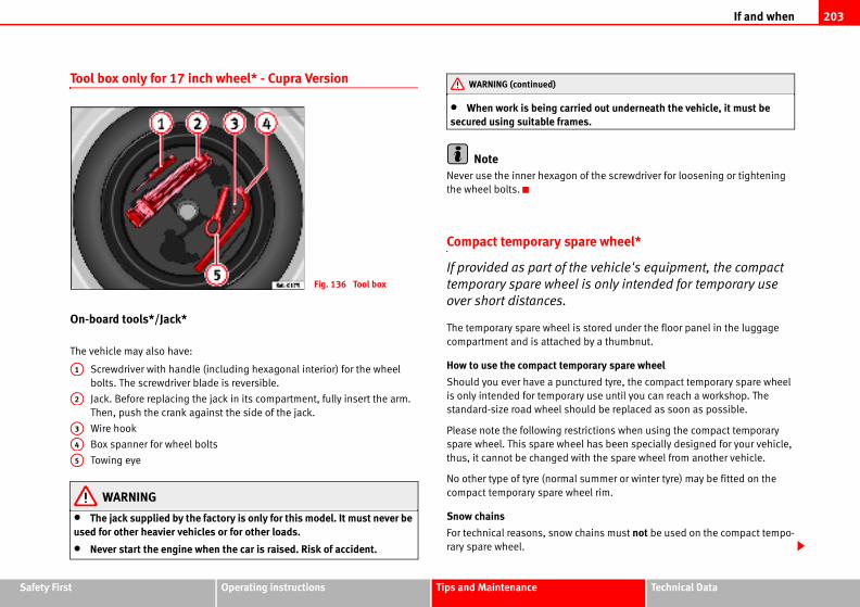
If and when 203
Safety Fir Technical Data
ied out underneath the vehicle, it must be es.
of the screwdriver for loosening or tightening
are wheel*
e vehicle's equipment, the compact
is only intended for temporary use
stored under the floor panel in the luggage
by a thumbnut.
porary spare wheel
tured tyre, the compact temporary spare wheel
y use until you can reach a workshop. The
uld be replaced as soon as possible.
trictions when using the compact temporary
l has been specially designed for your vehicle,
ith the spare wheel from another vehicle.
summer or winter tyre) may be fitted on the
eel rim.
hains must not be used on the compact tempo-
st Operating instructions Tips and Maintenance
Tool box only for 17 inch wheel* - Cupra Version
On-board tools*/Jack*
The vehicle may also have:
Screwdriver with handle (including hexagonal interior) for the wheel
bolts. The screwdriver blade is reversible.
Jack. Before replacing the jack in its compartment, fully insert the arm.
Then, push the crank against the side of the jack.
Wire hook
Box spanner for wheel bolts
Towing eye
WARNING
• The jack supplied by the factory is only for this model. It must never be used for other heavier vehicles or for other loads.
• Never start the engine when the car is raised. Risk of accident.
• When work is being carrsecured using suitable fram
NoteNever use the inner hexagon
the wheel bolts.
Compact temporary sp
If provided as part of th
temporary spare wheel
over short distances.
The temporary spare wheel is
compartment and is attached
How to use the compact tem
Should you ever have a punc
is only intended for temporar
standard-size road wheel sho
Please note the following res
spare wheel. This spare whee
thus, it cannot be changed w
No other type of tyre (normal
compact temporary spare wh
Snow chains
For technical reasons, snow c
rary spare wheel.
Fig. 136 Tool box
A1
A2
A3
A4
A5
WARNING (continued)
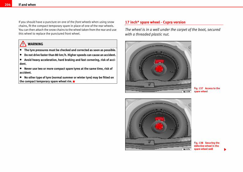
If and when204
Cupra version
der the carpet of the boot, secured
nut.
Fig. 137 Access to the spare wheel
Fig. 138 Securing the defective wheel in the spare wheel well
If you should have a puncture on one of the front wheels when using snow
chains, fit the compact temporary spare in place of one of the rear wheels.
You can then attach the snow chains to the wheel taken from the rear and use
this wheel to replace the punctured front wheel.
WARNING
• The tyre pressures must be checked and corrected as soon as possible.
• Do not drive faster than 80 km/h. Higher speeds can cause an accident.
• Avoid heavy acceleration, hard braking and fast cornering, risk of acci-dent.
• Never use two or more compact spare tyres at the same time, risk of accident.
• No other type of tyre (normal summer or winter tyre) may be fitted on the compact temporary spare wheel rim.
17 inch* spare wheel -
The wheel is in a well un
with a threaded plastic
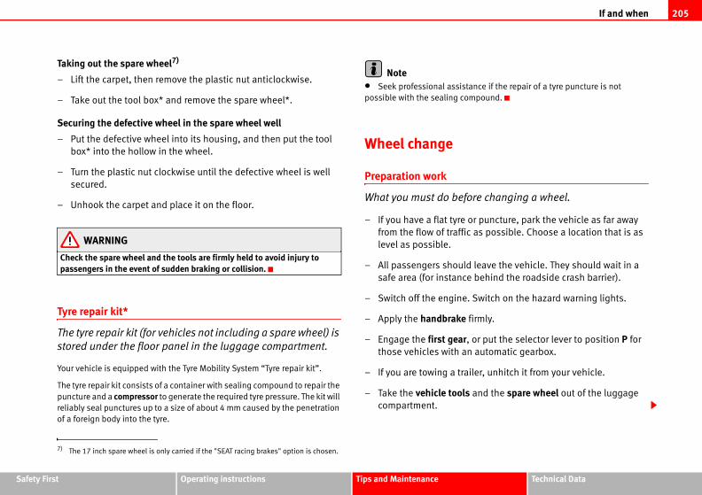
If and when 205
Safety Fir Technical Data
nce if the repair of a tyre puncture is not
pound.
re changing a wheel.
r puncture, park the vehicle as far away
as possible. Choose a location that is as
leave the vehicle. They should wait in a
behind the roadside crash barrier).
Switch on the hazard warning lights.
irmly.
or put the selector lever to position P for
automatic gearbox.
ler, unhitch it from your vehicle.
and the spare wheel out of the luggage
st Operating instructions Tips and Maintenance
Taking out the spare wheel7)
– Lift the carpet, then remove the plastic nut anticlockwise.
– Take out the tool box* and remove the spare wheel*.
Securing the defective wheel in the spare wheel well
– Put the defective wheel into its housing, and then put the tool
box* into the hollow in the wheel.
– Turn the plastic nut clockwise until the defective wheel is well
secured.
– Unhook the carpet and place it on the floor.
WARNING
Check the spare wheel and the tools are firmly held to avoid injury to passengers in the event of sudden braking or collision.
Tyre repair kit*
The tyre repair kit (for vehicles not including a spare wheel) is
stored under the floor panel in the luggage compartment.
Your vehicle is equipped with the Tyre Mobility System “Tyre repair kit”.
The tyre repair kit consists of a container with sealing compound to repair the
puncture and a compressor to generate the required tyre pressure. The kit will
reliably seal punctures up to a size of about 4 mm caused by the penetration
of a foreign body into the tyre.
Note• Seek professional assista
possible with the sealing com
Wheel change
Preparation work
What you must do befo
– If you have a flat tyre o
from the flow of traffic
level as possible.
– All passengers should
safe area (for instance
– Switch off the engine.
– Apply the handbrake f
– Engage the first gear,
those vehicles with an
– If you are towing a trai
– Take the vehicle tools
compartment.
7) The 17 inch spare wheel is only carried if the "SEAT racing brakes" option is chosen.
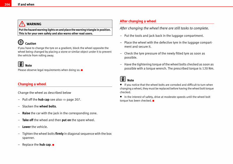
If and when206
l there are still tasks to complete.
ack in the luggage compartment.
e defective tyre in the luggage compart-
of the newly fitted tyre as soon as
ue of the wheel bolts checked as soon as
rench. The prescribed torque is 120 Nm.
l bolts are corroded and difficult to turn when
e replaced before having the wheel bolt torque
ive at moderate speeds until the wheel bolt
WARNING
Put the hazard warning lights on and place the warning triangle in position. This is for your own safety and also warns other road users.
CautionIf you have to change the tyre on a gradient, block the wheel opposite the
wheel being changed by placing a stone or similar object under it to prevent
the vehicle from rolling away.
NotePlease observe legal requirements when doing so.
Changing a wheel
Change the wheel as described below
– Pull off the hub cap see also ⇒ page 207.
– Slacken the wheel bolts.
– Raise the car with the jack in the corresponding zone.
– Take off the wheel and then put on the spare wheel.
– Lower the vehicle.
– Tighten the wheel bolts firmly in diagonal sequence with the box
spanner.
– Replace the hub cap.
After changing a wheel
After changing the whee
– Put the tools and jack b
– Place the wheel with th
ment and secure it.
– Check the tyre pressure
possible.
– Have the tightening torq
possible with a torque w
Note• If you notice that the whee
changing a wheel, they must b
checked.
• In the interest of safety, dr
torque has been checked.
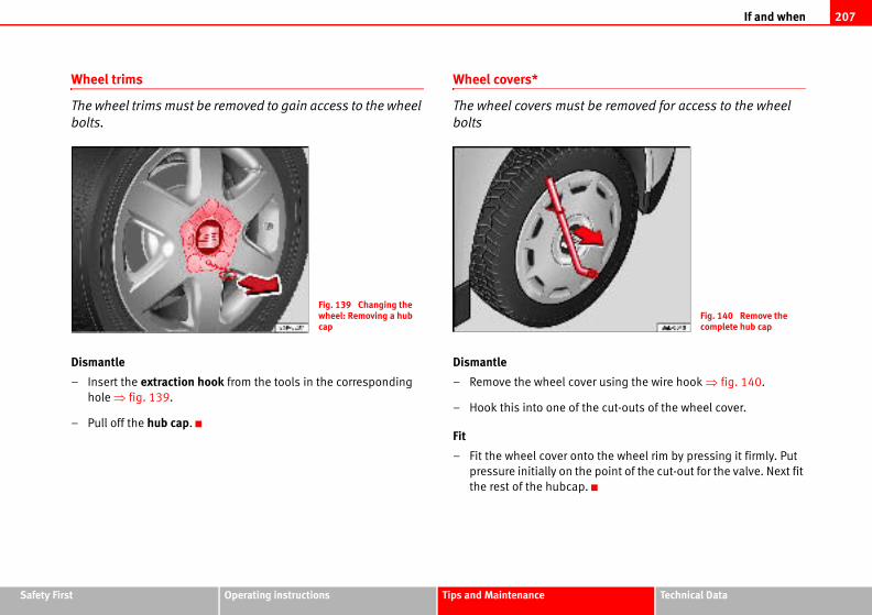
If and when 207
Safety Fir Technical Data
be removed for access to the wheel
er using the wire hook ⇒ fig. 140.
he cut-outs of the wheel cover.
o the wheel rim by pressing it firmly. Put
e point of the cut-out for the valve. Next fit
.
Fig. 140 Remove the complete hub cap
st Operating instructions Tips and Maintenance
Wheel trims
The wheel trims must be removed to gain access to the wheel
bolts.
Dismantle
– Insert the extraction hook from the tools in the corresponding
hole ⇒ fig. 139.
– Pull off the hub cap.
Wheel covers*
The wheel covers must
bolts
Dismantle
– Remove the wheel cov
– Hook this into one of t
Fit
– Fit the wheel cover ont
pressure initially on th
the rest of the hubcap
Fig. 139 Changing the wheel: Removing a hub cap
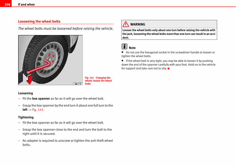
If and when208
about one turn before raising the vehicle with l bolts more than one turn can result in an acci-
socket in the screwdriver handle to loosen or
ht, you may be able to loosen it by pushing
carefully with your foot. Hold on to the vehicle
to slip.
Loosening the wheel bolts
The wheel bolts must be loosened before raising the vehicle.
Loosening
– Fit the box spanner as far as it will go over the wheel bolt.
– Grasp the box spanner by the end turn it about one full turn to the
left ⇒ fig. 141.
Tightening
– Fit the box spanner as far as it will go over the wheel bolt.
– Grasp the box spanner close to the end and turn the bolt to the
right until it is secured.
– An adapter is required to unscrew or tighten the anti-theft wheel
bolts.
WARNING
Loosen the wheel bolts only the jack, loosening the wheedent.
Note• Do not use the hexagonal
tighten the wheel bolts.
• If the wheel bolt is very tig
down the end of the spanner
for support and take care not
Fig. 141 Changing the wheel: loosen the wheel bolts
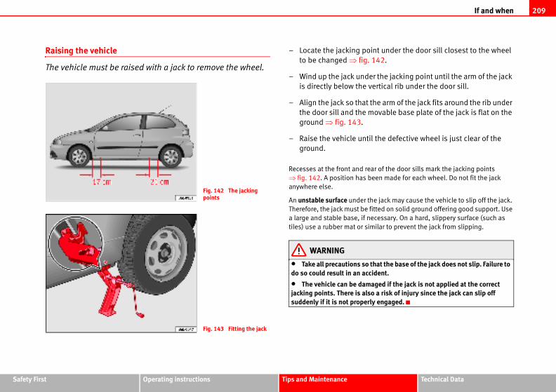
If and when 209
Safety Fir Technical Data
nt under the door sill closest to the wheel
42.
r the jacking point until the arm of the jack
rtical rib under the door sill.
e arm of the jack fits around the rib under
ovable base plate of the jack is flat on the
the defective wheel is just clear of the
r of the door sills mark the jacking points
en made for each wheel. Do not fit the jack
e jack may cause the vehicle to slip off the jack.
tted on solid ground offering good support. Use
cessary. On a hard, slippery surface (such as
ilar to prevent the jack from slipping.
at the base of the jack does not slip. Failure to dent.
ged if the jack is not applied at the correct a risk of injury since the jack can slip off engaged.
st Operating instructions Tips and Maintenance
Raising the vehicle
The vehicle must be raised with a jack to remove the wheel.
– Locate the jacking poi
to be changed ⇒ fig. 1
– Wind up the jack unde
is directly below the ve
– Align the jack so that th
the door sill and the m
ground ⇒ fig. 143.
– Raise the vehicle until
ground.
Recesses at the front and rea
⇒ fig. 142. A position has be
anywhere else.
An unstable surface under th
Therefore, the jack must be fi
a large and stable base, if ne
tiles) use a rubber mat or sim
WARNING
• Take all precautions so thdo so could result in an acci
• The vehicle can be damajacking points. There is alsosuddenly if it is not properly
Fig. 142 The jacking points
Fig. 143 Fitting the jack
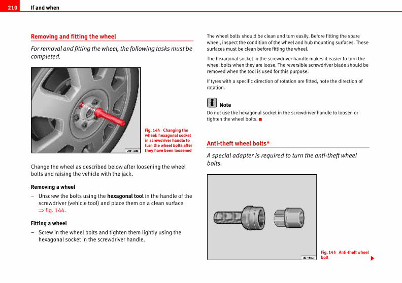
If and when210
an and turn easily. Before fitting the spare
f the wheel and hub mounting surfaces. These
fitting the wheel.
crewdriver handle makes it easier to turn the
se. The reversible screwdriver blade should be
d for this purpose.
n of rotation are fitted, note the direction of
ket in the screwdriver handle to loosen or
uired to turn the anti-theft wheel
Fig. 145 Anti-theft wheel bolt
Removing and fitting the wheel
For removal and fitting the wheel, the following tasks must be
completed.
Change the wheel as described below after loosening the wheel
bolts and raising the vehicle with the jack.
Removing a wheel
– Unscrew the bolts using the hexagonal tool in the handle of the
screwdriver (vehicle tool) and place them on a clean surface
⇒ fig. 144.
Fitting a wheel
– Screw in the wheel bolts and tighten them lightly using the
hexagonal socket in the screwdriver handle.
The wheel bolts should be cle
wheel, inspect the condition o
surfaces must be clean before
The hexagonal socket in the s
wheel bolts when they are loo
removed when the tool is use
If tyres with a specific directio
rotation.
NoteDo not use the hexagonal soc
tighten the wheel bolts.
Anti-theft wheel bolts*
A special adapter is req
bolts.
Fig. 144 Changing the wheel: hexagonal socket in screwdriver handle to turn the wheel bolts after they have been loosened
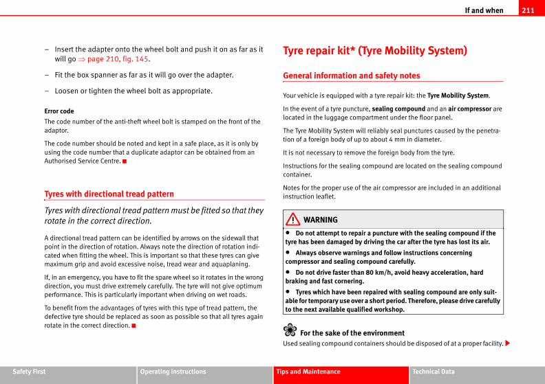
If and when 211
Safety Fir Technical Data
yre Mobility System)
d safety notes
a tyre repair kit: the Tyre Mobility System.
, sealing compound and an air compressor are
artment under the floor panel.
reliably seal punctures caused by the penetra-
about 4 mm in diameter.
the foreign body from the tyre.
mpound are located on the sealing compound
e air compressor are included in an additional
a puncture with the sealing compound if the riving the car after the tyre has lost its air.
s and follow instructions concerning pound carefully.
80 km/h, avoid heavy acceleration, hard
epaired with sealing compound are only suit- short period. Therefore, please drive carefully
ed workshop.
nvironmentainers should be disposed of at a proper facility.
st Operating instructions Tips and Maintenance
– Insert the adapter onto the wheel bolt and push it on as far as it
will go ⇒ page 210, fig. 145.
– Fit the box spanner as far as it will go over the adapter.
– Loosen or tighten the wheel bolt as appropriate.
Error code
The code number of the anti-theft wheel bolt is stamped on the front of the
adaptor.
The code number should be noted and kept in a safe place, as it is only by
using the code number that a duplicate adaptor can be obtained from an
Authorised Service Centre.
Tyres with directional tread pattern
Tyres with directional tread pattern must be fitted so that they
rotate in the correct direction.
A directional tread pattern can be identified by arrows on the sidewall that
point in the direction of rotation. Always note the direction of rotation indi-
cated when fitting the wheel. This is important so that these tyres can give
maximum grip and avoid excessive noise, tread wear and aquaplaning.
If, in an emergency, you have to fit the spare wheel so it rotates in the wrong
direction, you must drive extremely carefully. The tyre will not give optimum
performance. This is particularly important when driving on wet roads.
To benefit from the advantages of tyres with this type of tread pattern, the
defective tyre should be replaced as soon as possible so that all tyres again
rotate in the correct direction.
Tyre repair kit* (T
General information an
Your vehicle is equipped with
In the event of a tyre puncture
located in the luggage comp
The Tyre Mobility System will
tion of a foreign body of up to
It is not necessary to remove
Instructions for the sealing co
container.
Notes for the proper use of th
instruction leaflet.
WARNING
• Do not attempt to repairtyre has been damaged by d
• Always observe warningcompressor and sealing com
• Do not drive faster than braking and fast cornering.
• Tyres which have been rable for temporary use over ato the next available qualifi
For the sake of the eUsed sealing compound cont
If and when212
ents when doing so.
escribe the procedures for repairing
nd
container give detailed information on
compound.
ssor and hose from the container.
onto the valve.
ble into a 12 volt socket.
monitor the pressure shown on the pres-
r hose from the valve.
from the socket.
proper storing location.
NoteSeek professional assistance if the repair of a tyre puncture is not possible
with the sealing compound.
Preparation work
Certain steps must be taken before repairing a tyre.
– If you have a flat tyre or puncture, park the vehicle as far away
from the flow of traffic as possible.
– Apply the handbrake firmly.
– Engage the first gear, of put the selector lever to position P.
– All passengers should leave the vehicle. They should wait in a
safe area (for instance behind the roadside crash barrier).
– Check whether a repair is possible using the Tyre Mobility System
“General information and safety notes.”
– Unscrew inflation cap from the affected wheel.
– Take the tyre repair kit out of the luggage compartment.
WARNING
Put the hazard warning lights on and place the warning triangle in position. This is for your own safety and also warns other road users.
CautionTake special care if you have to repair a tyre on a gradient.
NotePlease observe legal requirem
Tyre repair
The following sections d
a tyre.
Using the sealing compou
– The instructions on the
how to use the sealing
Inflating the tyre.
– Remove the air compre
– Screw the retaining nut
– Plug the compressor ca
– Turn on compressor and
sure gauge.
Completing the repair
– Remove the compresso
– Fit the valve cap.
– Unplug the compressor
– Return all tools to their
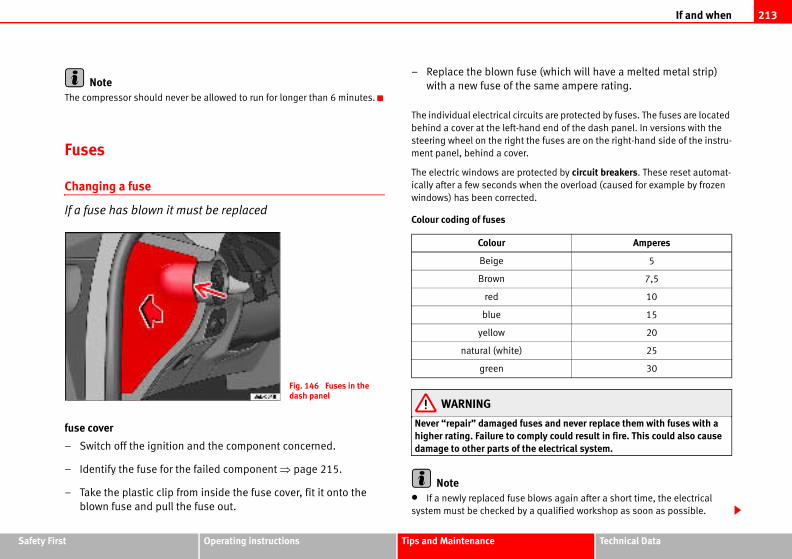
If and when 213
Safety Fir Technical Data
e (which will have a melted metal strip)
same ampere rating.
its are protected by fuses. The fuses are located
d end of the dash panel. In versions with the
e fuses are on the right-hand side of the instru-
tected by circuit breakers. These reset automat-
en the overload (caused for example by frozen
.
es and never replace them with fuses with a ply could result in fire. This could also cause
e electrical system.
lows again after a short time, the electrical
qualified workshop as soon as possible.
Amperes
5
7,5
10
15
20
25
30
st Operating instructions Tips and Maintenance
NoteThe compressor should never be allowed to run for longer than 6 minutes.
Fuses
Changing a fuse
If a fuse has blown it must be replaced
fuse cover
– Switch off the ignition and the component concerned.
– Identify the fuse for the failed component ⇒ page 215.
– Take the plastic clip from inside the fuse cover, fit it onto the
blown fuse and pull the fuse out.
– Replace the blown fus
with a new fuse of the
The individual electrical circu
behind a cover at the left-han
steering wheel on the right th
ment panel, behind a cover.
The electric windows are pro
ically after a few seconds wh
windows) has been corrected
Colour coding of fuses
WARNING
Never “repair” damaged fushigher rating. Failure to comdamage to other parts of th
Note• If a newly replaced fuse b
system must be checked by a
Fig. 146 Fuses in the dash panel
Colour
Beige
Brown
red
blue
yellow
natural (white)
green
If and when214
• If you replace a fuse with a stronger fuse, you could cause damage to
another location in the electrical system.
• Always keep some spare fuses in the vehicle. These are available from
SEAT dealers.
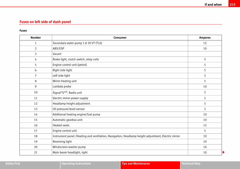
If and when 215
Safety Fir Technical Data
Amperes
15
10
5
5
5
5
5
10
5
5
5
5
10
10
15
5
Electric mirror 10
10
10
10
st Operating instructions Tips and Maintenance
Fuses on left side of dash panel
Fuses
Number Consumer
1 Secondary water pump 1.8 20 VT (T16)
2 ABS/ESP
3 Vacant
4 Brake light, clutch switch, relay coils
5 Engine control unit (petrol)
6 Right side light
7 Left side light
8 Mirror heating unit
9 Lambda probe
10 Signal“S”a). Radio unit
11 Electric mirror power supply
12 Headlamp height adjustment
13 Oil pressure/level sensor
14 Additional heating engine/fuel pump
15 Automatic gearbox unit
16 Heated seats
17 Engine control unit
18 Instrument panel /Heating and ventilation, Navigation, Headlamp height adjustment,
19 Reversing light
20 Windscreen washer pump
21 Main beam headlight, right
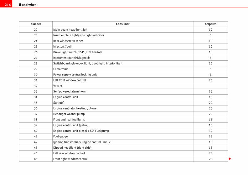
If and when216
10
5
10
10
10
5
10
5
5
25
15
15
20
25
20
15
15
30
15
15
15
25
25
Amperes
22 Main beam headlight, left
23 Number plate light/side light indicator
24 Rear windscreen wiper
25 Injectors(fuel)
26 Brake light switch /ESP (Turn sensor)
27 Instrument panel/Diagnosis
28 Switchboard: glovebox light, boot light, interior light
29 Climatronic
30 Power supply central locking unit
31 Left front window control
32 Vacant
33 Self powered alarm horn
34 Engine control unit
35 Sunroof
36 Engine ventilator heating /blower
37 Headlight washer pump
38 Front and rear fog lights
39 Engine control unit (petrol)
40 Engine control unit diesel + SDI Fuel pump
41 Fuel gauge
42 Ignition transformer+ Engine control unit T70
43 Dipped headlight (right side)
44 Left rear window control
45 Front right window control
Number Consumer
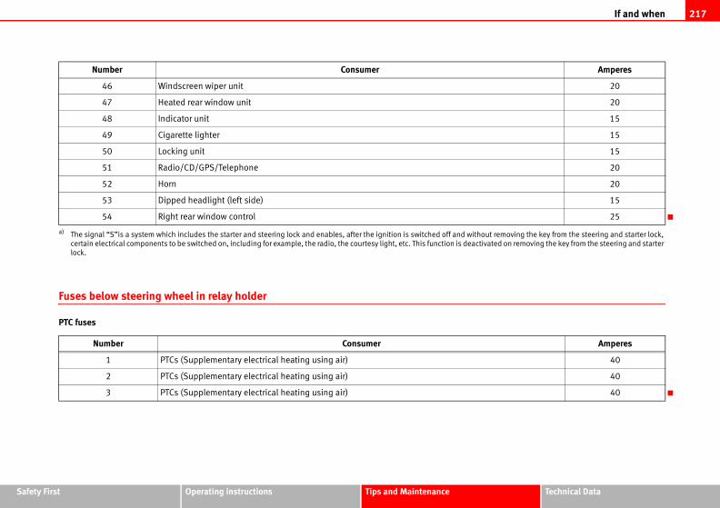
If and when 217
Safety Fir Technical Data
20
20
15
15
15
20
20
15
25
ut removing the key from the steering and starter lock,
vated on removing the key from the steering and starter
Amperes
40
40
40
Amperes
st Operating instructions Tips and Maintenance
Fuses below steering wheel in relay holder
PTC fuses
46 Windscreen wiper unit
47 Heated rear window unit
48 Indicator unit
49 Cigarette lighter
50 Locking unit
51 Radio/CD/GPS/Telephone
52 Horn
53 Dipped headlight (left side)
54 Right rear window control
a) The signal “S”is a system which includes the starter and steering lock and enables, after the ignition is switched off and witho
certain electrical components to be switched on, including for example, the radio, the courtesy light, etc. This function is deacti
lock.
Number Consumer
1 PTCs (Supplementary electrical heating using air)
2 PTCs (Supplementary electrical heating using air)
3 PTCs (Supplementary electrical heating using air)
Number Consumer
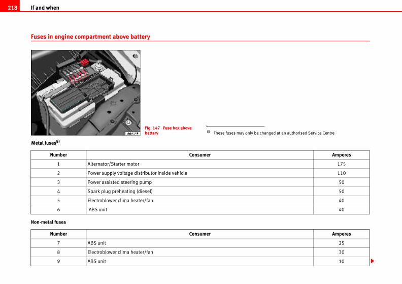
If and when218
ed at an authorised Service Centre
Amperes
175
110
50
50
40
40
Amperes
25
30
10
Fuses in engine compartment above battery
Metal fuses8)
Non-metal fuses
Fig. 147 Fuse box above battery 8) These fuses may only be chang
Number Consumer
1 Alternator/Starter motor
2 Power supply voltage distributor inside vehicle
3 Power assisted steering pump
4 Spark plug preheating (diesel)
5 Electroblower clima heater/fan
6 ABS unit
Number Consumer
7 ABS unit
8 Electroblower clima heater/fan
9 ABS unit
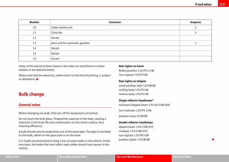
If and when 219
Safety Fir Technical Data
60/55W (H4)
5
5
5
Amperes
st Operating instructions Tips and Maintenance
Some of the electrical items listed in the table are only fitted on certain
models or are optional extras.
Please note that the above list, while correct at the time of printing, is subject
to alterations.
Bulb change
General notes
Before changing any bulb, first turn off the equipment concerned.
Do not touch the bulb glass. Fingerprints vaporise in the heat, causing a
reduction in the bulb life and condensation on the mirror surface, thus
reducing efficiency.
A bulb should only be replaced by one of the same type. The type is inscribed
on the bulb, either on the glass part or on the base.
It is highly recommended to keep a box of spare bulbs in the vehicle. At the
very least, the bulbs that most affect road safety should have spares in the
vehicle.
Rear lights on frame
Brake/position 12V/P21/5W
Turn signals 12V/P21W
Rear lights on tailgate
small position light 12V/W5W
antifog lamp 12V/P21W
reverse lamp 12V/P21W
Single reflector headlamps*
full beam/dipped beam 12V
turn indicator 12V/PY 21W
position lamp 12/W5W
Double reflector headlamps
dipped beam 12V/55W (H7)
roadway 12V/55W (H3)
turn signals 12V/PY21W
position lights 12V/W5W
10 Cable control unit
11 Clima fan
12 Vacant
13 Jatco unit for automatic gearbox
14 Vacant
15 Vacant
16 Vacant
Number Consumer
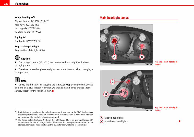
If and when220
Fig. 148 Main headlight lamps
Fig. 149 Main headlight lamps
Xenon headlights9)
Dipped beam 12V/35W (D1S) 10)
roadway 12V/55W (H7)
turn signals 12V/PY21W
position lights 12V/W5W
Fog lights*
Fog lights 12V/55W (H3)
Registration plate light
Registration plate light - C5W
Caution• The halogen lamps (H3, H7...) are pressurised and might explode on
changing them.
• Therefore protective gloves and glasses should be worn when changing a
halogen lamp.
Note• Due to the difficulty in accessing the lamps, any replacement work should
be done by a SEAT dealer. However, we shall explain how to change these
lamps, except for the xenon lights*.
Main headlight lamps
Dipped headlights
Main beam headlights
9) On this type of headlight, the bulb changes must be made by the SEAT dealer, given
that complex elements must be removed from the vehicle and a reset must be made
on the automatic control system incorporated.10) The Xenon bulbs discharge 2.5 times the light flux and have an average lifespan of 5
times more than that of halogen bulbs, this means that, except due to unusual circum-
stances, there is no need to change the bulbs for the whole life of the vehicle.
AA
AB
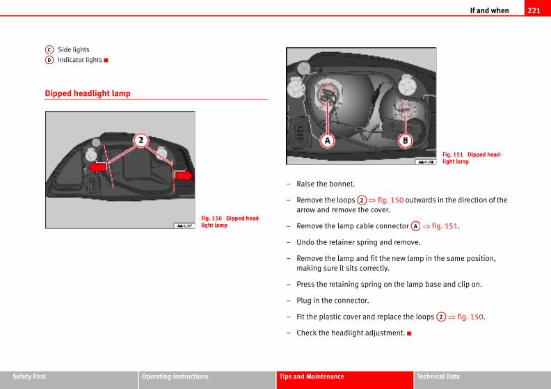
If and when 221
Safety Fir Technical Data
fig. 150 outwards in the direction of the
cover.
e connector ⇒ fig. 151.
g and remove.
fit the new lamp in the same position,
rectly.
ing on the lamp base and clip on.
d replace the loops ⇒ fig. 150.
justment.
Fig. 151 Dipped head-light lamp
AA
A2
st Operating instructions Tips and Maintenance
Side lights
Indicator lights
Dipped headlight lamp
– Raise the bonnet.
– Remove the loops ⇒arrow and remove the
– Remove the lamp cabl
– Undo the retainer sprin
– Remove the lamp and
making sure it sits cor
– Press the retaining spr
– Plug in the connector.
– Fit the plastic cover an
– Check the headlight ad
AC
AD
Fig. 150 Dipped head-light lamp
A2
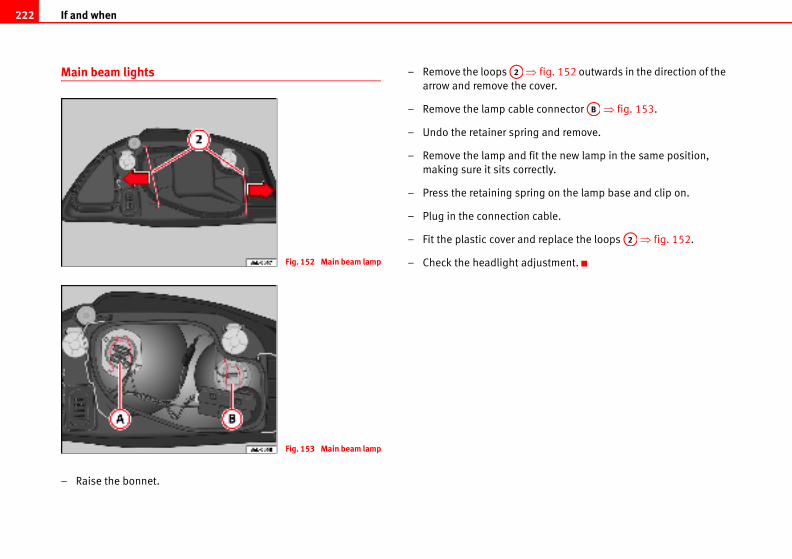
If and when222
fig. 152 outwards in the direction of the
over.
connector ⇒ fig. 153.
g and remove.
it the new lamp in the same position,
ectly.
ng on the lamp base and clip on.
cable.
replace the loops ⇒ fig. 152.
justment.
AB
A2
Main beam lights
– Raise the bonnet.
– Remove the loops ⇒arrow and remove the c
– Remove the lamp cable
– Undo the retainer sprin
– Remove the lamp and f
making sure it sits corr
– Press the retaining spri
– Plug in the connection
– Fit the plastic cover and
– Check the headlight adFig. 152 Main beam lamp
Fig. 153 Main beam lamp
A2
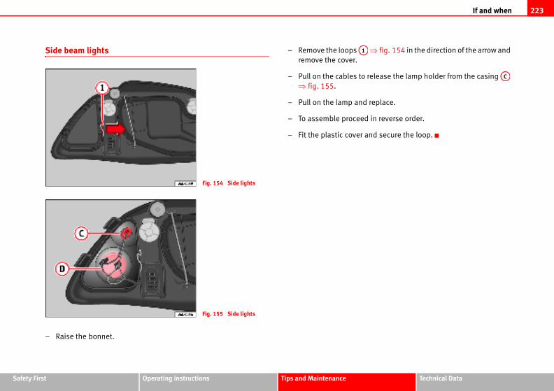
If and when 223
Safety Fir Technical Data
fig. 154 in the direction of the arrow and
lease the lamp holder from the casing
eplace.
n reverse order.
d secure the loop.
AC
st Operating instructions Tips and Maintenance
Side beam lights
– Raise the bonnet.
– Remove the loops ⇒remove the cover.
– Pull on the cables to re
⇒ fig. 155.
– Pull on the lamp and r
– To assemble proceed i
– Fit the plastic cover an
Fig. 154 Side lights
Fig. 155 Side lights
A1
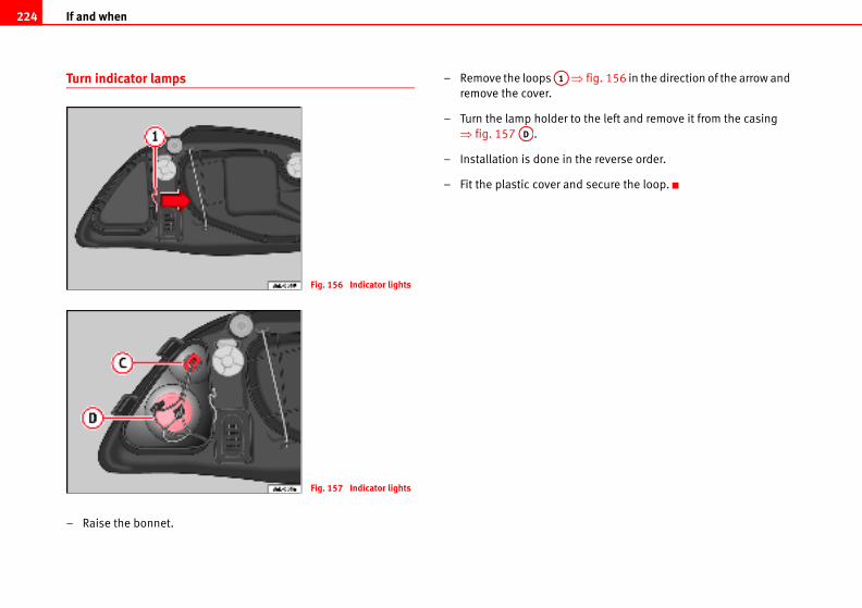
If and when224
fig. 156 in the direction of the arrow and
the left and remove it from the casing
he reverse order.
secure the loop.
Turn indicator lamps
– Raise the bonnet.
– Remove the loops ⇒remove the cover.
– Turn the lamp holder to
⇒ fig. 157 .
– Installation is done in t
– Fit the plastic cover and
Fig. 156 Indicator lights
Fig. 157 Indicator lights
A1
AD
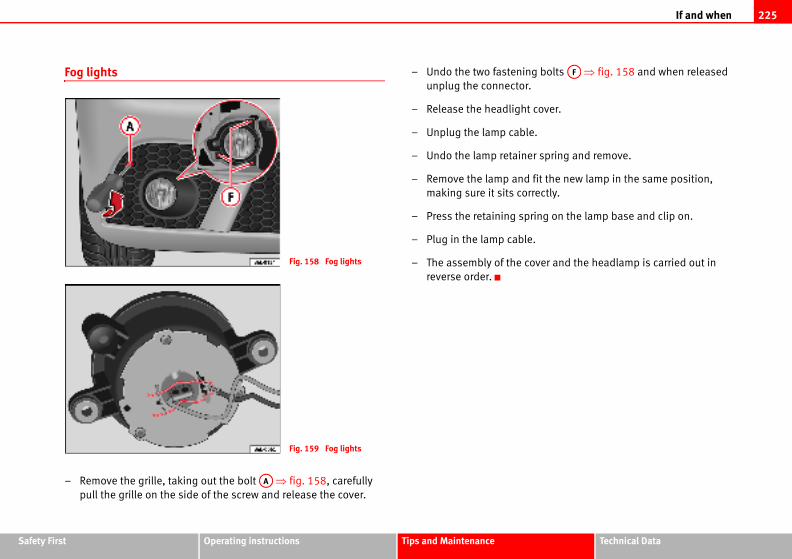
If and when 225
Safety Fir Technical Data
g bolts ⇒ fig. 158 and when released
cover.
.
r spring and remove.
fit the new lamp in the same position,
rectly.
ing on the lamp base and clip on.
.
ver and the headlamp is carried out in
AF
st Operating instructions Tips and Maintenance
Fog lights
– Remove the grille, taking out the bolt ⇒ fig. 158, carefully
pull the grille on the side of the screw and release the cover.
– Undo the two fastenin
unplug the connector.
– Release the headlight
– Unplug the lamp cable
– Undo the lamp retaine
– Remove the lamp and
making sure it sits cor
– Press the retaining spr
– Plug in the lamp cable
– The assembly of the co
reverse order.
Fig. 158 Fog lights
Fig. 159 Fog lights
AA
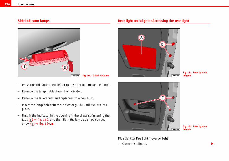
If and when226
ccessing the rear light
erse light
Fig. 161 Rear light on tailgate
Fig. 162 Rear light on tailgate
Side indicator lamps
– Press the indicator to the left or to the right to remove the lamp.
– Remove the lamp holder from the indicator.
– Remove the failed bulb and replace with a new bulb.
– Insert the lamp holder in the indicator guide until it clicks into
place.
– First fit the indicator in the opening in the chassis, fastening the
tabs ⇒ fig. 160, and then fit in the lamp as shown by the
arrow ⇒ fig. 160.
Rear light on tailgate: A
Side light 1/ Fog light/ rev
– Open the tailgate.
Fig. 160 Side indicators
A1
A2
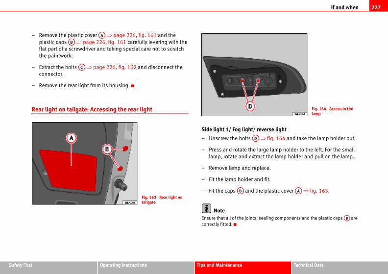
If and when 227
Safety Fir Technical Data
verse light
⇒ fig. 164 and take the lamp holder out.
rge lamp holder to the left. For the small
ct the lamp holder and pull on the lamp.
ace.
d fit.
e plastic cover ⇒ fig. 163.
ealing components and the plastic caps are
Fig. 164 Access to the lamp
AA
AB
st Operating instructions Tips and Maintenance
– Remove the plastic cover ⇒ page 226, fig. 161 and the
plastic caps ⇒ page 226, fig. 161 carefully levering with the
flat part of a screwdriver and taking special care not to scratch
the paintwork.
– Extract the bolts ⇒ page 226, fig. 162 and disconnect the
connector.
– Remove the rear light from its housing.
Rear light on tailgate: Accessing the rear light
Side light 1/ Fog light/ re
– Unscrew the bolts
– Press and rotate the la
lamp, rotate and extra
– Remove lamp and repl
– Fit the lamp holder an
– Fit the caps and th
NoteEnsure that all of the joints, s
correctly fitted.
AA
AB
AC
Fig. 163 Rear light on tailgate
AD
AB
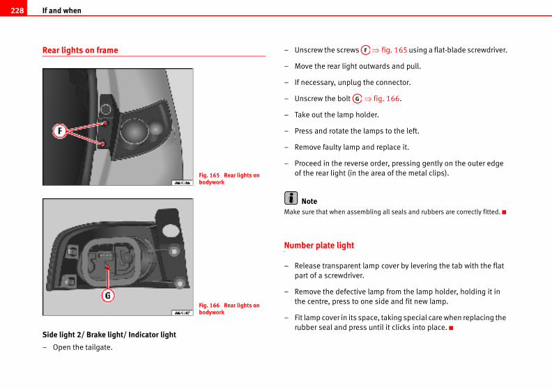
If and when228
⇒ fig. 165 using a flat-blade screwdriver.
wards and pull.
e connector.
fig. 166.
er.
ps to the left.
d replace it.
order, pressing gently on the outer edge
area of the metal clips).
ling all seals and rubbers are correctly fitted.
p cover by levering the tab with the flat
mp from the lamp holder, holding it in
side and fit new lamp.
ce, taking special care when replacing the
ntil it clicks into place.
Rear lights on frame
Side light 2/ Brake light/ Indicator light
– Open the tailgate.
– Unscrew the screws
– Move the rear light out
– If necessary, unplug th
– Unscrew the bolt ⇒
– Take out the lamp hold
– Press and rotate the lam
– Remove faulty lamp an
– Proceed in the reverse
of the rear light (in the
NoteMake sure that when assemb
Number plate light
– Release transparent lam
part of a screwdriver.
– Remove the defective la
the centre, press to one
– Fit lamp cover in its spa
rubber seal and press u
Fig. 165 Rear lights on bodywork
Fig. 166 Rear lights on bodywork
AF
AG
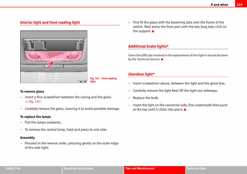
If and when 229
Safety Fir Technical Data
he fastening tabs over the frame of the
front part until the two long tabs click on
*
n the replacement of this light it should be done
ve, between the light and the glove box.
ght Next lift the light out sideways.
onnector side, first underneath then push
into place.
st Operating instructions Tips and Maintenance
Interior light and front reading light
To remove glass
– Insert a fine screwdriver between the casing and the glass
⇒ fig. 167.
– Carefully remove the glass, levering it to avoid possible damage.
To replace the lamps
– Pull the lamps outwards.
– To remove the central lamp, hold and press to one side.
Assembly
– Proceed in the reverse order, pressing gently on the outer edge
of the side light.
– First fit the glass with t
switch. Next press the
the support.
Additional brake lights
Given the difficulty involved i
by the Technical Service.
Glovebox light*
– Insert screwdriver abo
– Carefully remove the li
– Replace the bulb.
– Insert the light on the c
at the top until it clicks
Fig. 167 Front reading light
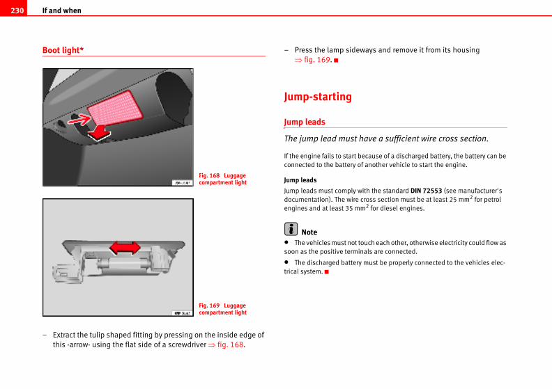
If and when230
s and remove it from its housing
e a sufficient wire cross section.
use of a discharged battery, the battery can be
other vehicle to start the engine.
the standard DIN 72553 (see manufacturer's
s section must be at least 25 mm2 for petrol
for diesel engines.
h each other, otherwise electricity could flow as
are connected.
st be properly connected to the vehicles elec-
Boot light*
– Extract the tulip shaped fitting by pressing on the inside edge of
this -arrow- using the flat side of a screwdriver ⇒ fig. 168.
– Press the lamp sideway
⇒ fig. 169.
Jump-starting
Jump leads
The jump lead must hav
If the engine fails to start beca
connected to the battery of an
Jump leads
Jump leads must comply with
documentation). The wire cros
engines and at least 35 mm2
Note• The vehicles must not touc
soon as the positive terminals
• The discharged battery mu
trical system.
Fig. 168 Luggage compartment light
Fig. 169 Luggage compartment light
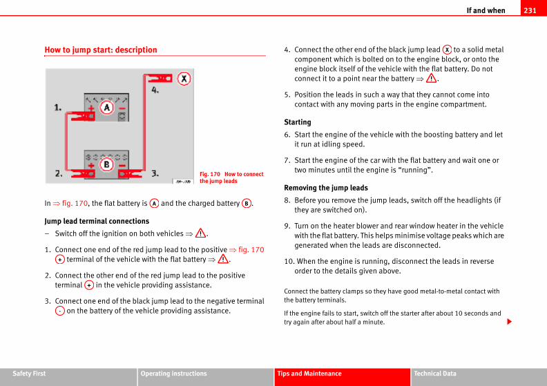
If and when 231
Safety Fir Technical Data
of the black jump lead to a solid metal
olted on to the engine block, or onto the
he vehicle with the flat battery. Do not
ar the battery ⇒ .
uch a way that they cannot come into
g parts in the engine compartment.
vehicle with the boosting battery and let
car with the flat battery and wait one or
ngine is “running”.
jump leads, switch off the headlights (if
wer and rear window heater in the vehicle
is helps minimise voltage peaks which are
ads are disconnected.
nning, disconnect the leads in reverse
en above.
o they have good metal-to-metal contact with
itch off the starter after about 10 seconds and
inute.
AX
st Operating instructions Tips and Maintenance
How to jump start: description
In ⇒ fig. 170, the flat battery is and the charged battery .
Jump lead terminal connections
– Switch off the ignition on both vehicles ⇒ .
1. Connect one end of the red jump lead to the positive ⇒ fig. 170
terminal of the vehicle with the flat battery ⇒ .
2. Connect the other end of the red jump lead to the positive
terminal in the vehicle providing assistance.
3. Connect one end of the black jump lead to the negative terminal
on the battery of the vehicle providing assistance.
4. Connect the other end
component which is b
engine block itself of t
connect it to a point ne
5. Position the leads in s
contact with any movin
Starting
6. Start the engine of the
it run at idling speed.
7. Start the engine of the
two minutes until the e
Removing the jump leads
8. Before you remove the
they are switched on).
9. Turn on the heater blo
with the flat battery. Th
generated when the le
10. When the engine is ru
order to the details giv
Connect the battery clamps s
the battery terminals.
If the engine fails to start, sw
try again after about half a m
Fig. 170 How to connect the jump leads
AA AB
A+
A+
A-
If and when232
WARNING
• Please note the safety warnings referring to working in the engine compartment ⇒ page 180, “Working in the engine compartment”.
• The battery providing assistance must have the same voltage as the flat battery (12V) and approximately the same capacity (see imprint on battery). Failure to comply could result in an explosion.
• Never use jump leads when one of the batteries is frozen. Danger of explosion! Even after the battery has thawed, battery acid could leak and cause chemical burns. If a battery freezes, it should be replaced.
• Keep sparks, flames and lighted cigarettes away from batteries, danger of explosion. Failure to comply could result in an explosion.
• Observe the instructions provided by the manufacturer of the jump leads.
• Do not connect the negative cable from the other vehicle directly to the negative terminal of the flat battery. The gas emitted from the battery could be ignited by sparks. Danger of explosion.
• Do not attach the negative cable from the other vehicle to parts of the fuel system or to the brake line.
• The non-insulated parts of the battery clamps must not be allowed to touch. The jump lead attached to the positive battery terminal must not touch metal parts of the vehicle, this can cause a short circuit.
• Position the leads in such a way that they cannot come into contact with any moving parts in the engine compartment.
• Do not bend over the batteries. This could result in chemical burns.
NoteThe vehicles must not touch each other, otherwise electricity could flow as
soon as the positive terminals are connected.
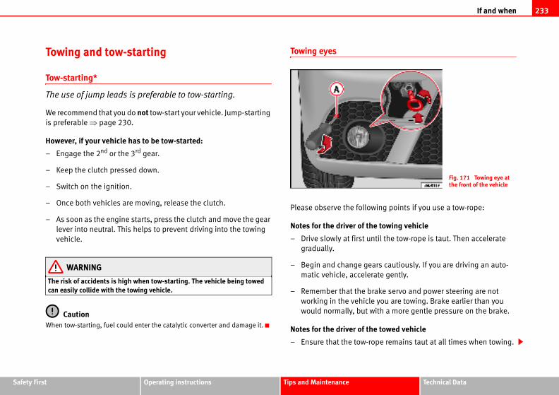
If and when 233
Safety Fir Technical Data
ing points if you use a tow-rope:
towing vehicle
til the tow-rope is taut. Then accelerate
rs cautiously. If you are driving an auto-
te gently.
ke servo and power steering are not
you are towing. Brake earlier than you
ith a more gentle pressure on the brake.
towed vehicle
pe remains taut at all times when towing.
Fig. 171 Towing eye at the front of the vehicle
st Operating instructions Tips and Maintenance
Towing and tow-starting
Tow-starting*
The use of jump leads is preferable to tow-starting.
We recommend that you do not tow-start your vehicle. Jump-starting
is preferable ⇒ page 230.
However, if your vehicle has to be tow-started:
– Engage the 2nd or the 3rd gear.
– Keep the clutch pressed down.
– Switch on the ignition.
– Once both vehicles are moving, release the clutch.
– As soon as the engine starts, press the clutch and move the gear
lever into neutral. This helps to prevent driving into the towing
vehicle.
WARNING
The risk of accidents is high when tow-starting. The vehicle being towed can easily collide with the towing vehicle.
CautionWhen tow-starting, fuel could enter the catalytic converter and damage it.
Towing eyes
Please observe the follow
Notes for the driver of the
– Drive slowly at first un
gradually.
– Begin and change gea
matic vehicle, accelera
– Remember that the bra
working in the vehicle
would normally, but w
Notes for the driver of the
– Ensure that the tow-ro
If and when234
ork if the engine is not running, you must apply
the brake pedal than you normally would.
does not work if the engine is not running, you
er than you normally would.
atic gearbox
position “N”.
km/h when towing a vehicle.
km.
sed, the vehicle must be towed with the front
ts when towing or tow-starting.
ing lights of both vehicles. However, observe
y.
icles with an automatic gearbox must not be
eans that there is no lubricant in the gearbox,
ls while the vehicle is being towed.
ed more than 50 km, the front wheels must be
ing should be carried out by a qualified person.
d when the vehicle has no electrical power. The
ith the front wheels raised. Towing should be
on.
ays be kept in the vehicle. Please refer to the
Fitting the front towing eye
– First remove the right hand cover from the lower part of the
bumper.
– Remove the bolt ⇒ page 233, fig. 171.
– Take the towing ring from the onboard tools.
– Rotate the towing ring to the left until it is completely tightened
into position.
– To remove the ring, rotate it to the right.
Tow-rope or tow-bar
It is easier and safer to tow a vehicle with a tow-bar. You should only use a
tow-rope if you do not have a tow-bar.
A tow-rope should be slightly elastic to reduce the loading on both vehicles.
It is advisable to use a tow-rope made of synthetic fibre or similarly elastic
material.
Attach the tow-rope or the tow-bar only to the towing eyes provided or a
towing bracket.
Driving style
Towing requires some experience, especially when using a tow-rope. Both
drivers should be familiar with the technique required for towing. Inexperi-
enced drivers should not attempt to tow-start or tow away another vehicle.
Do not pull too hard with the towing vehicle and take care to avoid jerking the
tow-rope. When towing on an unpaved road, there is always a risk of over-
loading and damaging the anchorage points.
The ignition of the vehicle being towed must be switched on to prevent the
steering wheel from locking and also to allow the use of the turn signals,
horn, windscreen wipers and washers.
As the brake servo does not w
considerably more pressure to
As the power assisted steering
will need more strength to ste
Towing vehicles with an autom
• Put the selector lever into
• Do not drive faster than 50
• Do not tow further than 50
• If a breakdown vehicle is u
wheels raised.
Note• Observe legal requiremen
• Switch on the hazard warn
any regulations to the contrar
• For technical reasons, veh
tow-started.
• If damage to your vehicle m
you must raise the drive whee
• If the vehicle has to be tow
raised during towing, and tow
• The steering wheel is locke
vehicle must then be towed w
carried out by a qualified pers
• The towing eye should alw
notes on ⇒ page 233.
AA
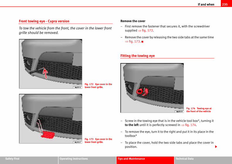
If and when 235
Safety Fir Technical Data
er that secures it, with the screwdriver
leasing the two side tabs at the same time
e that is in the vehicle tool box*, turning it
rfectly screwed in ⇒ fig. 174.
it to the right and put it in its place in the
d the two side tabs and place the cover in
Fig. 174 Towing eye at the front of the vehicle
st Operating instructions Tips and Maintenance
Front towing eye - Cupra version
To tow the vehicle from the front, the cover in the lower front
grille should be removed.
Remove the cover
– First remove the fasten
supplied ⇒ fig. 172.
– Remove the cover by re
⇒ fig. 173.
Fitting the towing eye
– Screw in the towing ey
to the left until it is pe
– To remove the eye, turn
toolbox*
– To place the cover, hol
position.
Fig. 172 Eye cover in the lower front grille.
Fig. 173 Eye cover in the lower front grille.
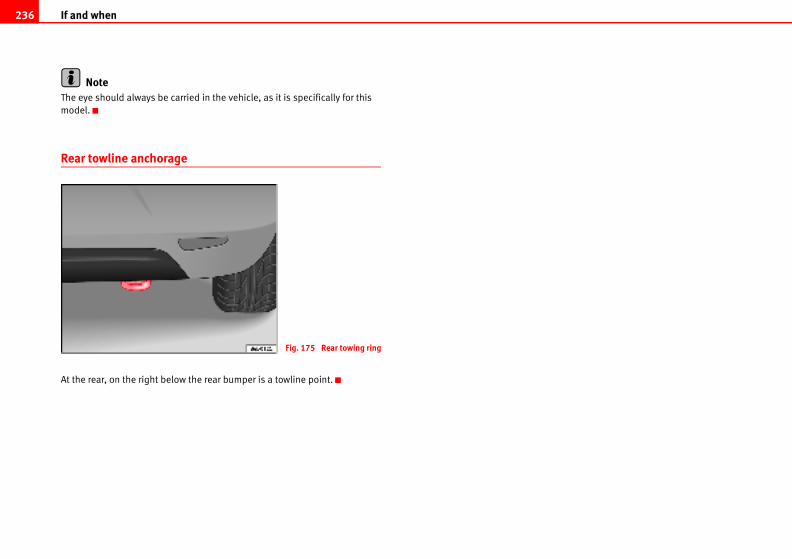
If and when236
NoteThe eye should always be carried in the vehicle, as it is specifically for this
model.
Rear towline anchorage
At the rear, on the right below the rear bumper is a towline point.
Fig. 175 Rear towing ring
General notes on the technical data 237
Safety Fir Technical Data
if additional equipment is fitted, for different
nd for other countries.
st Operating instructions Tips and Maintenance
Technical Data
General notes on the technical data
What you should be aware of
General notes
All data in the official vehicle documents take precedence over this data.
All data in these documents are valid for the basic model as offered in Spain.
The vehicle data card included in the Maintenance Programme or the vehicle
registration documents shows which engine is installed in the vehicle.
The figures may be different
models, for special vehicles a
Abbreviations used in this paragraph of the Technical Data
Abbreviation Meaning
kW Kilowatt, engine power measurement.
bhp Brake horse power, formerly used to denote engine power
at rpm Revolutions per minute - engine speed.
Nm Newton metres, unit of engine torque.
l/100 km Fuel consumption in litres per 100 kilometres
g/km Carbon dioxide emissions in grams per kilometre.
CO2 Carbon dioxide
CN Cetane number, indication of the ignition quality of the diesel.
RON Research octane number, indication of the knock resistance of petrol.
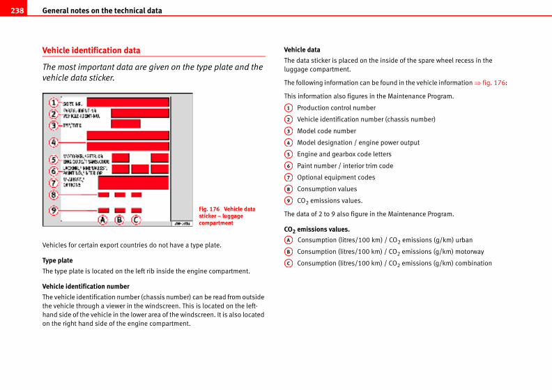
General notes on the technical data238
he inside of the spare wheel recess in the
be found in the vehicle information ⇒ fig. 176:
n the Maintenance Program.
er
ber (chassis number)
ne power output
letters
im code
s
n the Maintenance Program.
km) / CO2 emissions (g/km) urban
km) / CO2 emissions (g/km) motorway
km) / CO2 emissions (g/km) combination
Vehicle identification data
The most important data are given on the type plate and the
vehicle data sticker.
Vehicles for certain export countries do not have a type plate.
Type plate
The type plate is located on the left rib inside the engine compartment.
Vehicle identification number
The vehicle identification number (chassis number) can be read from outside
the vehicle through a viewer in the windscreen. This is located on the left-
hand side of the vehicle in the lower area of the windscreen. It is also located
on the right hand side of the engine compartment.
Vehicle data
The data sticker is placed on t
luggage compartment.
The following information can
This information also figures i
Production control numb
Vehicle identification num
Model code number
Model designation / engi
Engine and gearbox code
Paint number / interior tr
Optional equipment code
Consumption values
CO2 emissions values.
The data of 2 to 9 also figure i
CO2 emissions values.
Consumption (litres/100
Consumption (litres/100
Consumption (litres/100
Fig. 176 Vehicle data sticker – luggage compartment
A1
A2
A3
A4
A5
A6
A7
A8
A9
AB
AC
AA
General notes on the technical data 239
Safety Fir Technical Data
vehicle to another.
on figures are calculated in accordance with the
00/EC. These test requirements specify a real-
ormal everyday driving.
are applied:
in all gears, as in normal everyday driving. The
r the urban cycle and 63% for the extra urban
xide emissions. The gas composition is then
st Operating instructions Tips and Maintenance
How are the figures measured?
Fuel consumption
The consumption and emission details shown on the vehicle data sticker differ from one
The fuel consumption and CO2 emissions of the vehicle can be found on the
vehicle data sticker.
The fuel consumption and emissions figures given are based on the weight
category of the car, which is determined according to the engine/gearbox
combination and the equipment fitted.
The consumption and emissi
EC test requirements 1999/1
istic test method based on n
The following test conditions
Note• Actual consumption may vary from quoted test values, depending on
personal driving style, road and traffic conditions, the weather and the condi-
tion of the vehicle.
Urban cycle The urban cycle starts with an engine cold start. City driving is then simulated.
Extra urban cycleIn the extra urban cycle the vehicle undergoes frequent acceleration and braking
road speed ranges from 0 to 120 km/h.
CombinedThe average overall consumption is calculated with a weighting of around 37% fo
cycle.
CO2 emissionsThe exhaust gases are collected during both driving cycles to calculate carbon dio
analysed to evaluate the CO2 content and other emissions.
General notes on the technical data240
t exerted by the trailer drawbar on the ball joint
t exceed 75 kg.
e recommend that you always tow
awbar load. The response of the trailer on the
r load is too small.
rawbar load cannot be met (e.g. with small,
axle trailers or tandem axle trailers with an axle
least 4% of the actual trailer weight is a legal
.
ould not drive at speeds above 80 km/h when plies to countries where higher speeds are
m trailer weights or the draw bar loading. If the permissible total weight is exceeded, the vehicle may change, leading to accidents, ehicle.
ins, wheel bolts
ure values can be found on the inside of the
lues given there are for cold tyres. The slightly
s must not be reduced ⇒ .
Weights
Kerb weight refers to the basic model with a fuel tank filled to 90% capacity
and without optional extras. The figure quoted includes 75 kg to allow for the
weight of the driver.
For special versions and optional equipment fittings or for the addition of
accessories, the weight of the vehicle will increase ⇒ .
WARNING
• Please note that the centre of gravity may shift when transporting heavy objects; this may affect the vehicle's handling and lead to an acci-dent. Always adjust your speed and driving style to suit road conditions and requirements.
• Never exceed the gross axle weight rating or the gross vehicle weight rating. If the allowed axle load or the allowed total weight is exceeded, the driving characteristics of the vehicle may change, leading to accidents, injuries and damage to the vehicle.
Towing a trailer
Trailer weights
Trailer weights
The trailer weights and drawbar loads approved are selected in intensive
trials according to precisely defined criteria. The approved trailer weights are
valid for vehicles in the EU for maximum speeds of 80 km/h (in certain
circumstances up to 100 km/h). The figures may be different in other coun-
tries. All data in the official vehicle documents take precedence over these
data ⇒ .
Drawbar load
The maximum permitted weigh
of the towing bracket must no
In the interest of road safety, w
approaching the maximum dr
road will be poor if the drawba
If the maximum permissible d
empty and light-weight single
base of less than 1 metre), at
stipulation for a drawbar load
WARNING
• For safety reasons, you shtowing a trailer. This also appermitted.
• Never exceed the maximuthe permissible axle load or driving characteristics of theinjuries and damage to the v
Wheels
Tyre pressure, snow cha
Tyre pressures
The sticker with the tyre press
tank flap. The tyre pressure va
raised pressures of warm tyre
General notes on the technical data 241
Safety Fir Technical Data
st Operating instructions Tips and MaintenanceSnow chains
Snow chains are only permitted on the front wheels and only for tyres 155/80
R13; 165/70 R14 and 185/80 R14. Snow chains must have fine-pitch links
which do not protrude more than 15 mm, including tension device.
Remaining tyres can be fitted with chains no thicker than 9 mm.
Wheel bolts
After the wheels have been changed, the tightening torque of the wheel bolts
should be checked as soon as possible with a torque wrench ⇒ . The tight-
ening torque for steel and alloy wheels is 120 Nm.
WARNING
• Check the tyre pressure at least once per month. Correct tyre pressure is very important. If the tyre pressure is too high or too low, there is an increased danger of accidents, particularly at high speeds.
• If the torque of the wheel bolts is too low, they could loosen whilst the vehicle is in motion. Risk of accident! If the tightening torque is too high, the wheel bolts and threads could be damaged.
NoteWe recommend that you ask your Authorised Service Centre for information
about appropriate wheel, tyre and snow chain size.
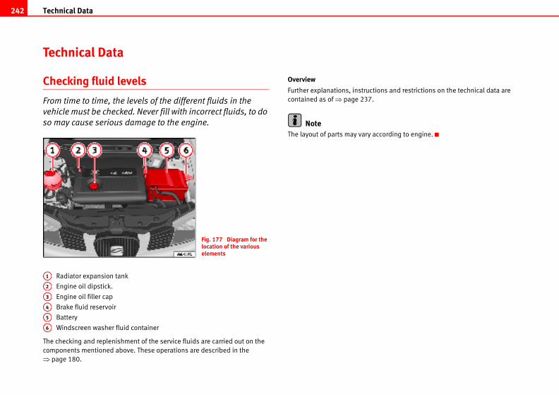
Technical Data242
ions and restrictions on the technical data are
ccording to engine.
Technical Data
Checking fluid levels
From time to time, the levels of the different fluids in the
vehicle must be checked. Never fill with incorrect fluids, to do
so may cause serious damage to the engine.
Radiator expansion tank
Engine oil dipstick.
Engine oil filler cap
Brake fluid reservoir
Battery
Windscreen washer fluid container
The checking and replenishment of the service fluids are carried out on the
components mentioned above. These operations are described in the
⇒ page 180.
Overview
Further explanations, instruct
contained as of ⇒ page 237.
NoteThe layout of parts may vary a
Fig. 177 Diagram for the location of the various elements
A1
A2
A3
A4
A5
A6
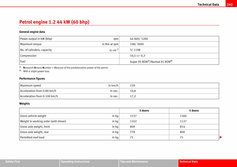
Technical Data 243
Safety Fir Technical Data
l 91 RONb)
5 doors
1560
1127
814
800
75
st Operating instructions Tips and Maintenance
Petrol engine 1.2 44 kW (60 bhp)
General engine data
Performance figures
Weights
Power output in kW (bhp) rpm 44 (60)/ 5200
Maximum torque in Nm at rpm 108/ 3000
No. of cylinders, capacity in cm 3 3/ 1198
Compression 10,5 +/- 0,3
Fuel Super 95 RONa)/Norma
a) Research-Octane-Number = Measure of the predetonation power of the petrol.b) With a slight power loss
Maximum speed in km/h 159
Acceleration from 0-80 km/h in sec. 10,8
Acceleration from 0-100 km/h in sec. 17,2
3 doors
Gross vehicle weight in kg 1537
Weight in working order (with driver) in kg 1102
Gross axle weight, front in kg 809
Gross axle weight, rear in kg 778
Permitted roof load in kg 75
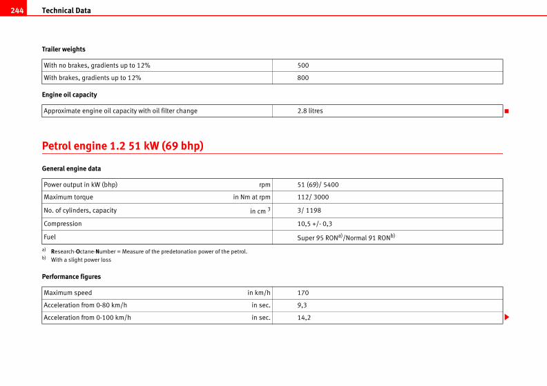
Technical Data244
91 RONb)
Trailer weights
Engine oil capacity
Petrol engine 1.2 51 kW (69 bhp)
General engine data
Performance figures
With no brakes, gradients up to 12% 500
With brakes, gradients up to 12% 800
Approximate engine oil capacity with oil filter change 2.8 litres
Power output in kW (bhp) rpm 51 (69)/ 5400
Maximum torque in Nm at rpm 112/ 3000
No. of cylinders, capacity in cm 3 3/ 1198
Compression 10,5 +/- 0,3
Fuel Super 95 RONa)/Normal
a) Research-Octane-Number = Measure of the predetonation power of the petrol.b) With a slight power loss
Maximum speed in km/h 170
Acceleration from 0-80 km/h in sec. 9,3
Acceleration from 0-100 km/h in sec. 14,2
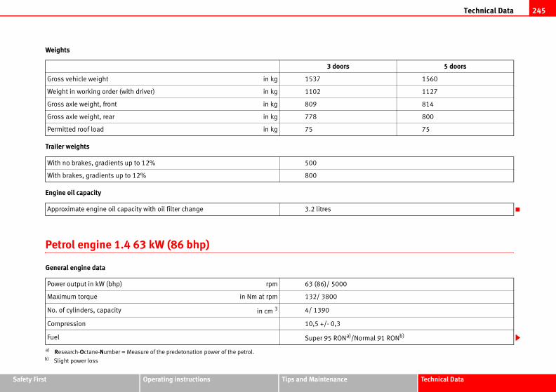
Technical Data 245
Safety Fir Technical Data
5 doors
1560
1127
814
800
75
l 91 RONb)
st Operating instructions Tips and Maintenance
Weights
Trailer weights
Engine oil capacity
Petrol engine 1.4 63 kW (86 bhp)
General engine data
3 doors
Gross vehicle weight in kg 1537
Weight in working order (with driver) in kg 1102
Gross axle weight, front in kg 809
Gross axle weight, rear in kg 778
Permitted roof load in kg 75
With no brakes, gradients up to 12% 500
With brakes, gradients up to 12% 800
Approximate engine oil capacity with oil filter change 3.2 litres
Power output in kW (bhp) rpm 63 (86)/ 5000
Maximum torque in Nm at rpm 132/ 3800
No. of cylinders, capacity in cm 3 4/ 1390
Compression 10,5 +/- 0,3
Fuel Super 95 RONa)/Norma
a) Research-Octane-Number = Measure of the predetonation power of the petrol.b) Slight power loss
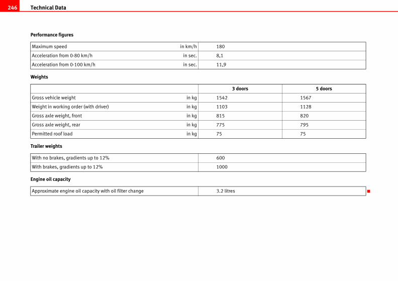
Technical Data246
5 doors
1567
1128
820
795
75
Performance figures
Weights
Trailer weights
Engine oil capacity
Maximum speed in km/h 180
Acceleration from 0-80 km/h in sec. 8,1
Acceleration from 0-100 km/h in sec. 11,9
3 doors
Gross vehicle weight in kg 1542
Weight in working order (with driver) in kg 1103
Gross axle weight, front in kg 815
Gross axle weight, rear in kg 775
Permitted roof load in kg 75
With no brakes, gradients up to 12% 600
With brakes, gradients up to 12% 1000
Approximate engine oil capacity with oil filter change 3.2 litres

Technical Data 247
Safety Fir Technical Data
l 91 RONb)
5 doors
1589
1169
860
795
75
st Operating instructions Tips and Maintenance
Petrol engine 1.4 litre 55 kW (75 hp). Automatic
General engine data
Performance figures
Weights
Power output in kW (bhp) rpm 55 (75)/ 5000
Maximum torque in Nm at rpm 126/ 3800
No. of cylinders, capacity in cm 3 4/ 1390
Compression 10,5
Fuel Super 95 RONa)/Norma
a) Research-Octane-Number = Measure of the predetonation power of the petrol.b) Slight power loss
Maximum speed in km/h 169
Acceleration from 0-80 km/h in sec. 10,1
Acceleration from 0-100 km/h in sec. 15,6
3 doors
Gross vehicle weight in kg 1562
Weight in working order (with driver) in kg 1142
Gross axle weight, front in kg 855
Gross axle weight, rear in kg 770
Permitted roof load in kg 75
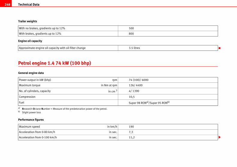
Technical Data248
5 RONb)
Trailer weights
Engine oil capacity
Petrol engine 1.4 74 kW (100 bhp)
General engine data
Performance figures
With no brakes, gradients up to 12% 500
With brakes, gradients up to 12% 800
Approximate engine oil capacity with oil filter change 3.5 litres
Power output in kW (bhp) rpm 74 (100)/ 6000
Maximum torque in Nm at rpm 126/ 4400
No. of cylinders, capacity in cm 3 4/ 1390
Compression 10,5
Fuel Super 98 RONa)/Super 9
a) Research-Octane-Number = Measure of the predetonation power of the petrol.b) Slight power loss
Maximum speed in km/h 190
Acceleration from 0-80 km/h in sec. 7,3
Acceleration from 0-100 km/h in sec. 11,2
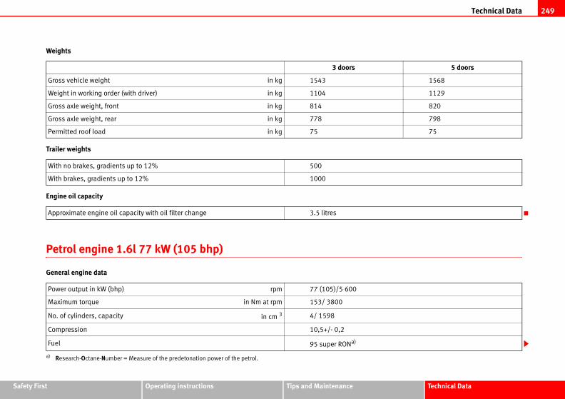
Technical Data 249
Safety Fir Technical Data
5 doors
1568
1129
820
798
75
st Operating instructions Tips and Maintenance
Weights
Trailer weights
Engine oil capacity
Petrol engine 1.6l 77 kW (105 bhp)
General engine data
3 doors
Gross vehicle weight in kg 1543
Weight in working order (with driver) in kg 1104
Gross axle weight, front in kg 814
Gross axle weight, rear in kg 778
Permitted roof load in kg 75
With no brakes, gradients up to 12% 500
With brakes, gradients up to 12% 1000
Approximate engine oil capacity with oil filter change 3.5 litres
Power output in kW (bhp) rpm 77 (105)/5 600
Maximum torque in Nm at rpm 153/ 3800
No. of cylinders, capacity in cm 3 4/ 1598
Compression 10,5+/- 0,2
Fuel 95 super RONa)
a) Research-Octane-Number = Measure of the predetonation power of the petrol.
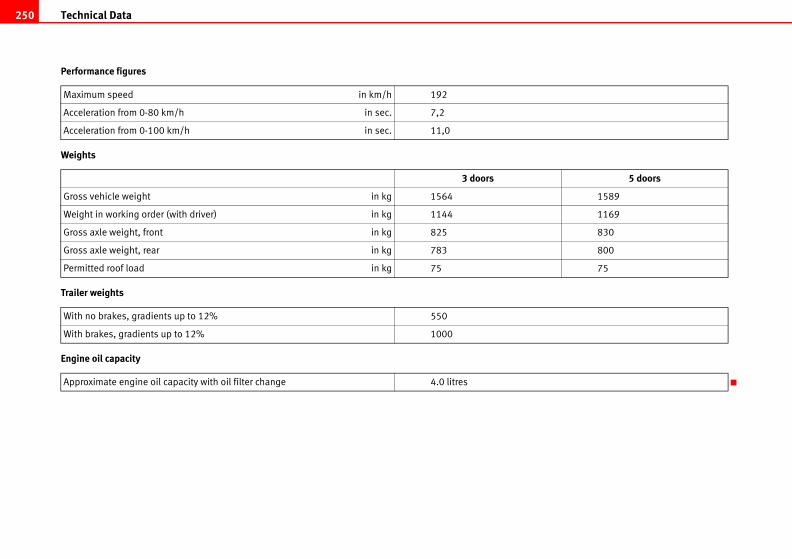
Technical Data250
5 doors
1589
1169
830
800
75
Performance figures
Weights
Trailer weights
Engine oil capacity
Maximum speed in km/h 192
Acceleration from 0-80 km/h in sec. 7,2
Acceleration from 0-100 km/h in sec. 11,0
3 doors
Gross vehicle weight in kg 1564
Weight in working order (with driver) in kg 1144
Gross axle weight, front in kg 825
Gross axle weight, rear in kg 783
Permitted roof load in kg 75
With no brakes, gradients up to 12% 550
With brakes, gradients up to 12% 1000
Approximate engine oil capacity with oil filter change 4.0 litres
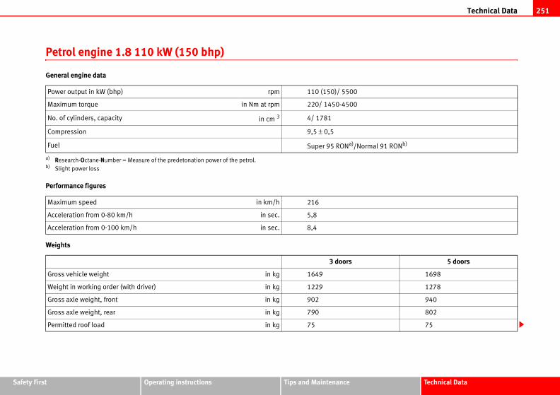
Technical Data 251
Safety Fir Technical Data
l 91 RONb)
5 doors
1698
1278
940
802
75
st Operating instructions Tips and Maintenance
Petrol engine 1.8 110 kW (150 bhp)
General engine data
Performance figures
Weights
Power output in kW (bhp) rpm 110 (150)/ 5500
Maximum torque in Nm at rpm 220/ 1450-4500
No. of cylinders, capacity in cm 3 4/ 1781
Compression 9,5 ± 0,5
Fuel Super 95 RONa)/Norma
a) Research-Octane-Number = Measure of the predetonation power of the petrol.b) Slight power loss
Maximum speed in km/h 216
Acceleration from 0-80 km/h in sec. 5,8
Acceleration from 0-100 km/h in sec. 8,4
3 doors
Gross vehicle weight in kg 1649
Weight in working order (with driver) in kg 1229
Gross axle weight, front in kg 902
Gross axle weight, rear in kg 790
Permitted roof load in kg 75
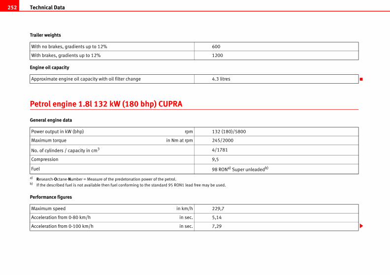
Technical Data252
db)
Trailer weights
Engine oil capacity
Petrol engine 1.8l 132 kW (180 bhp) CUPRA
General engine data
Performance figures
With no brakes, gradients up to 12% 600
With brakes, gradients up to 12% 1200
Approximate engine oil capacity with oil filter change 4.3 litres
Power output in kW (bhp) rpm 132 (180)/5800
Maximum torque in Nm at rpm 245/2000
No. of cylinders / capacity in cm3 4/1781
Compression 9,5
Fuel 98 RONa) Super unleade
a) Research-Octane-Number = Measure of the predetonation power of the petrol.b) If the described fuel is not available then fuel conforming to the standard 95 RON1 lead free may be used.
Maximum speed in km/h 229,7
Acceleration from 0-80 km/h in sec. 5,14
Acceleration from 0-100 km/h in sec. 7,29
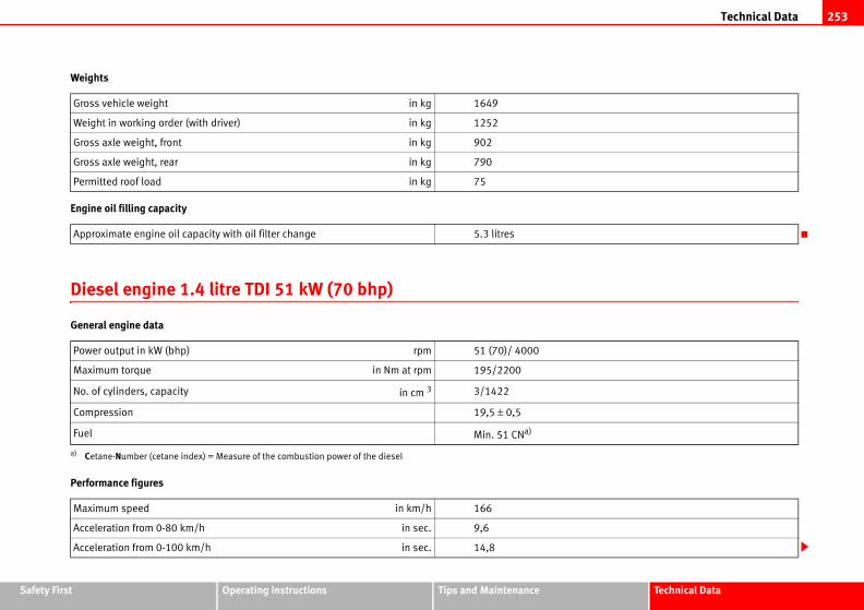
Technical Data 253
Safety Fir Technical Data
st Operating instructions Tips and MaintenanceWeights
Engine oil filling capacity
Diesel engine 1.4 litre TDI 51 kW (70 bhp)
General engine data
Performance figures
Gross vehicle weight in kg 1649
Weight in working order (with driver) in kg 1252
Gross axle weight, front in kg 902
Gross axle weight, rear in kg 790
Permitted roof load in kg 75
Approximate engine oil capacity with oil filter change 5.3 litres
Power output in kW (bhp) rpm 51 (70)/ 4000
Maximum torque in Nm at rpm 195/2200
No. of cylinders, capacity in cm 3 3/1422
Compression 19,5 ± 0,5
Fuel Min. 51 CNa)
a) Cetane-Number (cetane index) = Measure of the combustion power of the diesel
Maximum speed in km/h 166
Acceleration from 0-80 km/h in sec. 9,6
Acceleration from 0-100 km/h in sec. 14,8
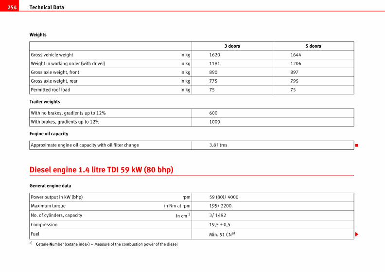
Technical Data254
5 doors
1644
1206
897
795
75
Weights
Trailer weights
Engine oil capacity
Diesel engine 1.4 litre TDI 59 kW (80 bhp)
General engine data
3 doors
Gross vehicle weight in kg 1620
Weight in working order (with driver) in kg 1181
Gross axle weight, front in kg 890
Gross axle weight, rear in kg 775
Permitted roof load in kg 75
With no brakes, gradients up to 12% 600
With brakes, gradients up to 12% 1000
Approximate engine oil capacity with oil filter change 3.8 litres
Power output in kW (bhp) rpm 59 (80)/ 4000
Maximum torque in Nm at rpm 195/ 2200
No. of cylinders, capacity in cm 3 3/ 1492
Compression 19,5 ± 0,5
Fuel Min. 51 CNa)
a) Cetane-Number (cetane index) = Measure of the combustion power of the diesel
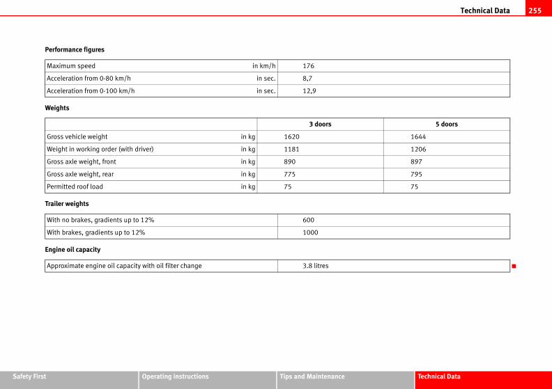
Technical Data 255
Safety Fir Technical Data
5 doors
1644
1206
897
795
75
st Operating instructions Tips and Maintenance
Performance figures
Weights
Trailer weights
Engine oil capacity
Maximum speed in km/h 176
Acceleration from 0-80 km/h in sec. 8,7
Acceleration from 0-100 km/h in sec. 12,9
3 doors
Gross vehicle weight in kg 1620
Weight in working order (with driver) in kg 1181
Gross axle weight, front in kg 890
Gross axle weight, rear in kg 775
Permitted roof load in kg 75
With no brakes, gradients up to 12% 600
With brakes, gradients up to 12% 1000
Approximate engine oil capacity with oil filter change 3.8 litres
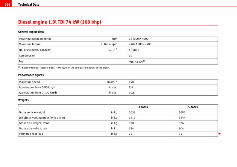
Technical Data256
5 doors
1682
1244
926
804
75
Diesel engine 1.9l TDI 74 kW (100 bhp)
General engine data
Performance figures
Weights
Power output in kW (bhp) rpm 74 (100)/ 4000
Maximum torque in Nm at rpm 240/ 1800 - 2400
No. of cylinders, capacity in cm 3 4/ 1896
Compression 19
Fuel Min. 51 CNa)
a) Cetane-Number (cetane index) = Measure of the combustion power of the diesel.
Maximum speed in km/h 190
Acceleration from 0-80 km/h in sec. 7,4
Acceleration from 0-100 km/h in sec. 10,8
3 doors
Gross vehicle weight in kg 1658
Weight in working order (with driver) in kg 1219
Gross axle weight, front in kg 920
Gross axle weight, rear in kg 784
Permitted roof load in kg 75
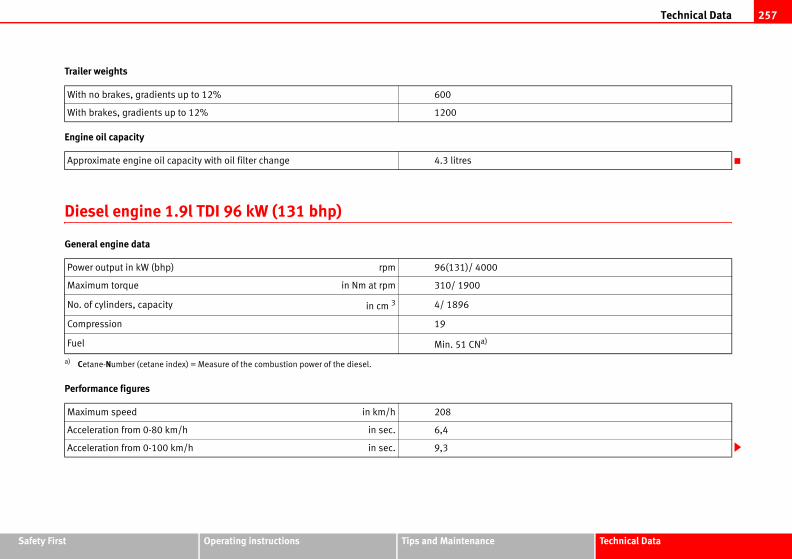
Technical Data 257
Safety Fir Technical Data
st Operating instructions Tips and MaintenanceTrailer weights
Engine oil capacity
Diesel engine 1.9l TDI 96 kW (131 bhp)
General engine data
Performance figures
With no brakes, gradients up to 12% 600
With brakes, gradients up to 12% 1200
Approximate engine oil capacity with oil filter change 4.3 litres
Power output in kW (bhp) rpm 96(131)/ 4000
Maximum torque in Nm at rpm 310/ 1900
No. of cylinders, capacity in cm 3 4/ 1896
Compression 19
Fuel Min. 51 CNa)
a) Cetane-Number (cetane index) = Measure of the combustion power of the diesel.
Maximum speed in km/h 208
Acceleration from 0-80 km/h in sec. 6,4
Acceleration from 0-100 km/h in sec. 9,3
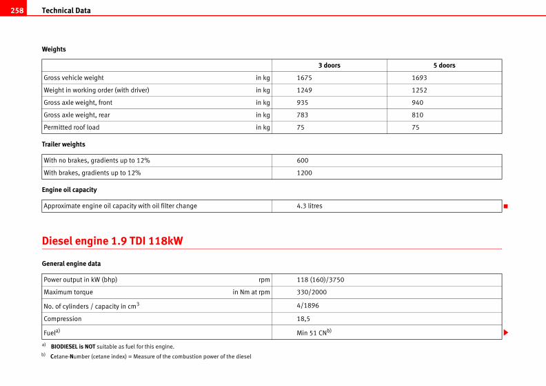
Technical Data258
5 doors
1693
1252
940
810
75
Weights
Trailer weights
Engine oil capacity
Diesel engine 1.9 TDI 118kW
General engine data
3 doors
Gross vehicle weight in kg 1675
Weight in working order (with driver) in kg 1249
Gross axle weight, front in kg 935
Gross axle weight, rear in kg 783
Permitted roof load in kg 75
With no brakes, gradients up to 12% 600
With brakes, gradients up to 12% 1200
Approximate engine oil capacity with oil filter change 4.3 litres
Power output in kW (bhp) rpm 118 (160)/3750
Maximum torque in Nm at rpm 330/2000
No. of cylinders / capacity in cm3 4/1896
Compression 18,5
Fuela)
a) BIODIESEL is NOT suitable as fuel for this engine.
Min 51 CNb)
b) Cetane-Number (cetane index) = Measure of the combustion power of the diesel
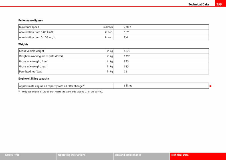
Technical Data 259
Safety Fir Technical Data
st Operating instructions Tips and MaintenancePerformance figures
Weights
Engine oil filling capacity
Maximum speed in km/h 220,2
Acceleration from 0-80 km/h in sec. 5,25
Acceleration from 0-100 km/h in sec. 7,6
Gross vehicle weight in kg 1675
Weight in working order (with driver) in kg 1290
Gross axle weight, front in kg 935
Gross axle weight, rear in kg 783
Permitted roof load in kg 75
Approximate engine oil capacity with oil filter changea)
a) Only use engine oil 0W-30 that meets the standards VW506 01 or VW 507 00.
5 litres
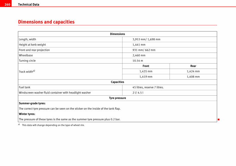
Technical Data260
Rear
1,424 mm
1,408 mm
tres.
Dimensions and capacities
Dimensions
Length, width 3,953 mm/ 1,698 mm
Height at kerb weight 1,441 mm
Front and rear projection 931 mm/ 662 mm
Wheelbase 2,460 mm
Turning circle 10.54 m
Track widtha)
a) This data will change depending on the type of wheel rim.
Front
1,435 mm
1,419 mm
Capacities
Fuel tank 45 litres, reserve 7 li
Windscreen washer fluid container with headlight washer 2 l/ 4.5 l
Tyre pressure
Summer-grade tyres:
The correct tyre pressure can be seen on the sticker on the inside of the tank flap.
Winter tyres:
The pressure of these tyres is the same as the summer tyre pressure plus 0.2 bar.
Index 261
iliary audio connection: AUX-IN . . . . . . . . . 115
coupling . . . . . . . . . . . . . . . . . . . . . . . . . . . 159
. . . . . . . . . . . . . . . . . . . . . . . . . . . . . . . . . . . 147
tery
Changing . . . . . . . . . . . . . . . . . . . . . . . . . . . 195
Charging . . . . . . . . . . . . . . . . . . . . . . . . . . . . 195
Winter conditions . . . . . . . . . . . . . . . . . . . . 194
tension device
Disposal . . . . . . . . . . . . . . . . . . . . . . . . . . . . . 24
Warning lamp . . . . . . . . . . . . . . . . . . . . . . . . 27
tension devices . . . . . . . . . . . . . . . . . . . . . . 24
diesel . . . . . . . . . . . . . . . . . . . . . . . . . . . . . . 179
net . . . . . . . . . . . . . . . . . . . . . . . . . . . . . . . . 182
t* . . . . . . . . . . . . . . . . . . . . . . . . . . . . . . 96, 230
ke assist system . . . . . . . . . . . . . . . . . . . . . 147
ke fluid . . . . . . . . . . . . . . . . . . . . . . . . . . . . . 192
Changing . . . . . . . . . . . . . . . . . . . . . . . . . . . 193
ke pads . . . . . . . . . . . . . . . . . . . . . . . . 151, 152
ke servo . . . . . . . . . . . . . . . . . . . . . . . 147, 152
ke system . . . . . . . . . . . . . . . . . . . . . . . . . . . 192
Warning lamp . . . . . . . . . . . . . . . . . . . . . . . . 65
kes . . . . . . . . . . . . . . . . . . . . . . . . . . . . . . . . 152
king distance . . . . . . . . . . . . . . . . . . . . . . . . 152
b changes
general notes . . . . . . . . . . . . . . . . . . . . . . . . 219
Index
AABS . . . . . . . . . . . . . . . . . . . . . . . . . . . . . . . . . . . 148
Warning lamp . . . . . . . . . . . . . . . . . . . . . . . . . 64
Accessories . . . . . . . . . . . . . . . . . . . . . . . . . . . . 172
Acoustic signal . . . . . . . . . . . . . . . . . . . . . . . . . . 16
Acoustic warning . . . . . . . . . . . . . . . . . . . . . . . . 132
Adjustable service interval display . . . . . . . . . . 58
Adjusting simple headlights
driving on the left . . . . . . . . . . . . . . . . . . . . 154
driving on the right . . . . . . . . . . . . . . . . . . . 154
Adjusting the seat belt height . . . . . . . . . . . . . . 23
Air conditioning system
Climatronic . . . . . . . . . . . . . . . . . . . . . . . . . . 125
General notes . . . . . . . . . . . . . . . . . . . . . . . . 128
Air conditioning* . . . . . . . . . . . . . . . . . . . . . . . . 122
Air outlets . . . . . . . . . . . . . . . . . . . . . . . . . . . . . . 121
Air recirculation
Semi-automatic air conditioning . . . . . . . . 124
Air recirculation mode
Climatronic . . . . . . . . . . . . . . . . . . . . . . . . . . 127
Airbag covers . . . . . . . . . . . . . . . . . . . . . . . . . . . . 31
Airbag system . . . . . . . . . . . . . . . . . . . . . . . . . . . 26
Curtain airbags . . . . . . . . . . . . . . . . . . . . . . . 37
Front airbags . . . . . . . . . . . . . . . . . . . . . . . . . 29
Side airbags . . . . . . . . . . . . . . . . . . . . . . . . . . 33
Warning lamp . . . . . . . . . . . . . . . . . . . . . . . . . 27
Airbags
Care . . . . . . . . . . . . . . . . . . . . . . . . . . . . . . . . 28
Disposal . . . . . . . . . . . . . . . . . . . . . . . . . . . . . 28
Safety notes . . . . . . . . . . . . . . . . . . . . . . . . . . 28
Alarm system
Switching off . . . . . . . . . . . . . . . . . . . . . . . . . 81
Alterations to the vehicle . . . . . . . . . . . . . . . . . 172
Alternator
Warning lamp . . . . . . . . . . . . . . . . . . . . . . . . . 62
Ambient temperature display . . . . . . . . . . . . 55, 57
Anti-freeze . . . . . . . . . . . . . . . . . . . . . . . . . . . . . 187
Anti-lock brake system . . . . . . . . . . . . . . . . . . . 148
Warning lamp . . . . . . . . . . . . . . . . . . . . . . . . . 64
Anti-theft alarm system . . . . . . . . . . . . . . . . . . . . 80
Switching off . . . . . . . . . . . . . . . . . . . . . . . . . 81
Anti-theft wheel bolts . . . . . . . . . . . . . . . . . . . . 208
Aquaplaning . . . . . . . . . . . . . . . . . . . . . . . . . . . 198
Athermic windscreen* . . . . . . . . . . . . . . . . . . . . 100
Automatic anti-dazzle interior mirror*
Activating the anti-dazzle function . . . . . . 101
Deactivating anti-dazzle function . . . . . . . . 101
Automatic car washes . . . . . . . . . . . . . . . . . . . . 164
Automatic gearbox . . . . . . . . . . . . . . . . . . . . . . 137
Instructions for driving . . . . . . . . . . . . . . . . 139
Kick-down feature . . . . . . . . . . . . . . . . . . . . 139
Selector lever positions . . . . . . . . . . . . . . . . 138
Automatic wiper/wash function for the rear window
99
Aux
BBall
BAS
Bat
Belt
Belt
Bio
Bon
Boo
Bra
Bra
Bra
Bra
Bra
Bra
Bra
Bul
Index262
ning cloth seat covers . . . . . . . . . . . . . . . . 170
ning dash panel . . . . . . . . . . . . . . . . . . . . . 170
ning engine compartment . . . . . . . . . . . . . 169
ning fabric trim . . . . . . . . . . . . . . . . . . . . . 170
ning leather . . . . . . . . . . . . . . . . . . . . . . . . 170
ning plastic parts . . . . . . . . . . . . . . . . . . . . 170
ning seat belts . . . . . . . . . . . . . . . . . . . . . . 171
ning steel wheels . . . . . . . . . . . . . . . . . . . . 168
ning windows . . . . . . . . . . . . . . . . . . . . . . . 166
ning wooden trim . . . . . . . . . . . . . . . . . . . . 170
atronic
utomatic mode . . . . . . . . . . . . . . . . . . . . . 126
ontrols . . . . . . . . . . . . . . . . . . . . . . . . . . . . 125
eneral notes . . . . . . . . . . . . . . . . . . . . . . . 128
anual mode . . . . . . . . . . . . . . . . . . . . . . . 127
k . . . . . . . . . . . . . . . . . . . . . . . . . . . . . . . . . . 54
pit . . . . . . . . . . . . . . . . . . . . . . . . . . . . . . . . . 51
ector for Apple iPod . . . . . . . . . . . . . . . . . 115
rol
ight switches . . . . . . . . . . . . . . . . . . . . . . . . 90
ing mirrors . . . . . . . . . . . . . . . . . . . . . . . . 102
rol lamps . . . . . . . . . . . . . . . . . . . . . . . . . . . 60
rol lighting . . . . . . . . . . . . . . . . . . . . . . . . . . 51
rols
lectric windows . . . . . . . . . . . . . . . . . . . . . . 84
enience closing
liding/tilting roof . . . . . . . . . . . . . . . . . . . . 88
indows . . . . . . . . . . . . . . . . . . . . . . . . . . . . 86
enience opening
indows . . . . . . . . . . . . . . . . . . . . . . . . . . . . 86
Buzzer . . . . . . . . . . . . . . . . . . . . . . . . . . . . . 94, 132
CCar care
Exterior . . . . . . . . . . . . . . . . . . . . . . . . . . . . . 164
Car care products . . . . . . . . . . . . . . . . . . . . . . . 163
Car phone . . . . . . . . . . . . . . . . . . . . . . . . . . . . . 173
Car washes . . . . . . . . . . . . . . . . . . . . . . . . . . . . 164
Catalytic converter . . . . . . . . . . . . . . . . . . . . . . 152
Central locking . . . . . . . . . . . . . . . . . . . . . . . . . . 70
Automatic speed dependent locking and un-
locking system* . . . . . . . . . . . . . . . . . . . . . 72
Emergency unlocking system . . . . . . . . . . . . 73
Locking system for involuntary unlocking . . 72
Selective unlocking system* . . . . . . . . . . . . 72
Unlocking system* . . . . . . . . . . . . . . . . . . . . 72
Central locking button
Central locking . . . . . . . . . . . . . . . . . . . . . . . 73
unlocking . . . . . . . . . . . . . . . . . . . . . . . . . . . . 73
Cetane number . . . . . . . . . . . . . . . . . . . . . . . . . 179
Change lamps
dipped headlight lamp . . . . . . . . . . . . . . . . 221
Changing gear
See Manual gearbox . . . . . . . . . . . . . . . . . . 136
Changing lamps
interior light and reading light . . . . . . . . . . 229
rear light units on the boot: access to the lamp
227
rear light units on the boot: access to the rear
light . . . . . . . . . . . . . . . . . . . . . . . . . . . . . . 226
changing lamps
rear lights on frame . . . . . . . . . . . . . . . . . . . 228
Changing the lamps
glovebox light* . . . . . . . . . . . . . . . . . . . . . . 229
indicator lights . . . . . . . . . . . . . . . . . . . . . . 224
main beam lights . . . . . . . . . . . . . . . . . . . . 222
Main headlight lamps . . . . . . . . . . . . . . . . . 220
number plate light . . . . . . . . . . . . . . . . . . . 228
side beam lights . . . . . . . . . . . . . . . . . . . . . 223
Side indicator lights . . . . . . . . . . . . . . . . . . 226
Changing windscreen wiper blades . . . . . . . . . 190
Chassis number . . . . . . . . . . . . . . . . . . . . . . . . 238
Checking . . . . . . . . . . . . . . . . . . . . . . . . . . . . . . 195
Checking battery electrolyte level . . . . . . . . . . 195
Checking engine oil level . . . . . . . . . . . . . . . . . 185
Child safety . . . . . . . . . . . . . . . . . . . . . . . . . . . . . 42
Child seat . . . . . . . . . . . . . . . . . . . . . . . . . . . . . . . 44
Categorisation in groups . . . . . . . . . . . . . . . 44
Group 1 . . . . . . . . . . . . . . . . . . . . . . . . . . . . . 45
Group 2 . . . . . . . . . . . . . . . . . . . . . . . . . . . . . 45
Group 3 . . . . . . . . . . . . . . . . . . . . . . . . . . . . . 45
Groups 0 and 0+ . . . . . . . . . . . . . . . . . . . . . . 44
Safety notes . . . . . . . . . . . . . . . . . . . . . . . . . . 43
Securing . . . . . . . . . . . . . . . . . . . . . . . . . . . . . 47
Child seats
ISOFIX and Toptether system . . . . . . . . . . . . 48
on the front passenger seat . . . . . . . . . . . . . 27
Cigarette lighter . . . . . . . . . . . . . . . . . . . . . . . . 114
Cleaning alloy wheels . . . . . . . . . . . . . . . . . . . . 168
Cleaning and caring for your vehicle . . . . . . . . 163
Cleaning chrome . . . . . . . . . . . . . . . . . . . . . . . . 167
Clea
Clea
Clea
Clea
Clea
Clea
Clea
Clea
Clea
Clea
Clim
a
c
G
m
Cloc
Cock
Conn
Cont
L
w
Cont
Cont
Cont
E
Conv
S
W
Conv
W
Index 263
trohydraulic steering
warning lamp . . . . . . . . . . . . . . . . . . . . . . . . . 62
tronic differential lock . . . . . . . . . . . . . . . . 150
Warning lamp . . . . . . . . . . . . . . . . . . . . . . . . 64
tronic immobiliser . . . . . . . . . . . . . . . . 67, 133
tronic stabilisation program . . . . . . . . . . . 149
tronic stabilisation programme . . . . . . . . . . 66
Description . . . . . . . . . . . . . . . . . . . . . . . . . . 131
Warning lamp . . . . . . . . . . . . . . . . . . . . . . . 132
tronic stabilisation programme (ESP)
warning lamp . . . . . . . . . . . . . . . . . . . . . . . . . 66
ssion control system
warning lamp . . . . . . . . . . . . . . . . . . . . . . . . . 65
ine
Running in . . . . . . . . . . . . . . . . . . . . . . . . . . 151
ine compartment
Working in the engine compartment . . . . . 180
ine coolant . . . . . . . . . . . . . . . . . . . . . . . . . . 187
ine fault
warning lamp . . . . . . . . . . . . . . . . . . . . . . . . . 63
ine management
Warning lamp . . . . . . . . . . . . . . . . . . . . . . . . 63
ine oil . . . . . . . . . . . . . . . . . . . . . . . . . . . . . . 183
Changing . . . . . . . . . . . . . . . . . . . . . . . . . . . 186
Checking level . . . . . . . . . . . . . . . . . . . . . . . 185
Oil properties . . . . . . . . . . . . . . . . . . . . . . . . 184
Specifications . . . . . . . . . . . . . . . . . . . . . . . 183
Topping up . . . . . . . . . . . . . . . . . . . . . . . . . . 186
ine oil dipstick . . . . . . . . . . . . . . . . . . . . . . . 185
ine oil pressure
Warning lamp . . . . . . . . . . . . . . . . . . . . . . . . 67
Coolant . . . . . . . . . . . . . . . . . . . . . . . . . . . 187, 188
Coolant Level . . . . . . . . . . . . . . . . . . . . . . . . . . . 188
Coolant level
warning light . . . . . . . . . . . . . . . . . . . . . . . . . 63
Coolant Loss . . . . . . . . . . . . . . . . . . . . . . . . . . . 188
Coolant temperature
Display . . . . . . . . . . . . . . . . . . . . . . . . . . . . . . 53
Safety instructions . . . . . . . . . . . . . . . . . . . . . 64
Correct adjustment of front head restraints . . . . 12
Cruise control system . . . . . . . . . . . . . . . . . . . . 142
Curtain airbags . . . . . . . . . . . . . . . . . . . . . . . . . . 37
Description . . . . . . . . . . . . . . . . . . . . . . . . . . . 37
Function . . . . . . . . . . . . . . . . . . . . . . . . . . . . . 38
Safety notes . . . . . . . . . . . . . . . . . . . . . . . . . . 38
DDanger of fitting a child seat on the front passenger
seat . . . . . . . . . . . . . . . . . . . . . . . . . . . . . . . 27
Deep Water in Cupra version . . . . . . . . . . . . . . 151
Diesel . . . . . . . . . . . . . . . . . . . . . . . . . . . . . . . . . 179
Diesel engine
Winter driving . . . . . . . . . . . . . . . . . . . . . . . . 180
Diesel engine particulate filter* . . . . . . . . . . . . 153
Differential lock . . . . . . . . . . . . . . . . . . . . . . . . . 150
Differential lock fault (EDL)
warning lamp . . . . . . . . . . . . . . . . . . . . . . . . . 67
Digital clock . . . . . . . . . . . . . . . . . . . . . . . . . . . . . 54
Dipped headlights . . . . . . . . . . . . . . . . . . . . . . . . 90
Disabling front passenger airbag
Safety notes . . . . . . . . . . . . . . . . . . . . . . . . . . 41
Disabling the airbag
Disabling front passenger airbag . . . . . . . . . 40
Displays in the Multi-function display
Memory displays . . . . . . . . . . . . . . . . . . . . . . 56
Door lock cylinders . . . . . . . . . . . . . . . . . . . . . . 167
Door release lever . . . . . . . . . . . . . . . . . . . . . . . . 51
Doors
Childproof locks . . . . . . . . . . . . . . . . . . . . . . . 74
Unlocking and locking . . . . . . . . . . . . . . . . . 70
Drive wheels traction control system . . . . . . . . 148
Driving
Driving abroad . . . . . . . . . . . . . . . . . . . . . . . 153
Economically / With Respect for the
Environment . . . . . . . . . . . . . . . . . . . . . . . 160
With a trailer . . . . . . . . . . . . . . . . . . . . . . . . . 159
with a trailer . . . . . . . . . . . . . . . . . . . . . . . . . 158
Driving abroad . . . . . . . . . . . . . . . . . . . . . . . . . . 153
Headlights . . . . . . . . . . . . . . . . . . . . . . . . . . 154
Driving economically . . . . . . . . . . . . . . . . . . . . . 160
Driving safety . . . . . . . . . . . . . . . . . . . . . . . . . . . . . 8
Driving with respect for the environment . . . . . 160
Duplicate keys . . . . . . . . . . . . . . . . . . . . . . . . . . . 77
Dust filter . . . . . . . . . . . . . . . . . . . . . . . . . . . . . . 128
Dynamic headlight range control . . . . . . . . . . . . 91
EEDL . . . . . . . . . . . . . . . . . . . . . . . . . . . . . . . . . . . 150
EDS
Warning lamp . . . . . . . . . . . . . . . . . . . . . . . . . 64
Electrical sockets . . . . . . . . . . . . . . . . . . . . . . . . 114
Elec
Elec
Elec
Elec
Elec
Elec
Emi
Eng
Eng
Eng
Eng
Eng
Eng
Eng
Eng
Index264
ed front seats . . . . . . . . . . . . . . . . . . . . . . 108
ing and ventilation . . . . . . . . . . . . . . . . . . 119
ing system . . . . . . . . . . . . . . . . . . . . . . . . . 120
pressure cleaners . . . . . . . . . . . . . . . . . . . 165
. . . . . . . . . . . . . . . . . . . . . . . . . . . . . . . . . . . 51
to jump start description . . . . . . . . . . . . . 231
tification number . . . . . . . . . . . . . . . . . . . . 238
ion key . . . . . . . . . . . . . . . . . . . . . . . . . . . . 132
ion lock . . . . . . . . . . . . . . . . . . . . . . . . . . . . 132
ator lights
ndication lamp . . . . . . . . . . . . . . . . . . . . . . . 63
ument and switch lighting . . . . . . . . . . . . . 91
ument lighting . . . . . . . . . . . . . . . . . . . . . . . 51
ument panel . . . . . . . . . . . . . . . . . . . . . . . . . 51
uments . . . . . . . . . . . . . . . . . . . . . . . . . . . . . 52
mittent wipe, windscreen . . . . . . . . . . . . . . 97
IX and Toptether system . . . . . . . . . . . . . . . 48
leads . . . . . . . . . . . . . . . . . . . . . . . . . . . . . 230
-starting . . . . . . . . . . . . . . . . . . . . . . . . . . . 230
ab . . . . . . . . . . . . . . . . . . . . . . . . . . . . . . . . . 76
. . . . . . . . . . . . . . . . . . . . . . . . . . . . . . . . . . . 76
Environment . . . . . . . . . . . . . . . . . . . . . . . . . . . 160
Environmental friendliness . . . . . . . . . . . . 161
Environmental tip
Avoiding pollution . . . . . . . . . . . . . . . . . . . . 178
ESP . . . . . . . . . . . . . . . . . . . . . . . . . . . . . . . . 66, 149
Exhaust gasses purification system . . . . . . . . 152
Exterior mirrors . . . . . . . . . . . . . . . . . . . . . . . . . 166
External aerial . . . . . . . . . . . . . . . . . . . . . . . . . . 173
FFloor mats . . . . . . . . . . . . . . . . . . . . . . . . . . . . . . 14
Fog lights . . . . . . . . . . . . . . . . . . . . . . . . . . . . . . . 90
Front airbags . . . . . . . . . . . . . . . . . . . . . . . . . . . . 29
Description . . . . . . . . . . . . . . . . . . . . . . . . . . 29
Function . . . . . . . . . . . . . . . . . . . . . . . . . . . . . 30
Safety notes . . . . . . . . . . . . . . . . . . . . . . . . . . 32
Front ashtray . . . . . . . . . . . . . . . . . . . . . . . . . . . 113
Front cup holder* . . . . . . . . . . . . . . . . . . . . . . . 112
Front interior light . . . . . . . . . . . . . . . . . . . . . . . . 95
Front passenger airbag deactivation . . . . . . . . . 40
Front reading light . . . . . . . . . . . . . . . . . . . . . . . . 95
Front seat adjustment
Lumbar support . . . . . . . . . . . . . . . . . . . . . . 107
Fuel
Diesel . . . . . . . . . . . . . . . . . . . . . . . . . . . . . . 179
Petrol . . . . . . . . . . . . . . . . . . . . . . . . . . . . . . 178
Fuel level
Indicator . . . . . . . . . . . . . . . . . . . . . . . . . . . . . 54
Fuel reserve . . . . . . . . . . . . . . . . . . . . . . . . . . . . . 64
Fuel Tank
Opening the fuel tank flap . . . . . . . . . . . . . 177
Fuel tank
See Fuel reserve . . . . . . . . . . . . . . . . . . . . . . 64
Fuel: save . . . . . . . . . . . . . . . . . . . . . . . . . . . . . . 160
Fuses . . . . . . . . . . . . . . . . . . . . . . . . . . . . . . . . . 213
GG 12 . . . . . . . . . . . . . . . . . . . . . . . . . . . . . . . . . . 187
Gear shift pattern . . . . . . . . . . . . . . . . . . . . . . . 136
General overview of the engine compartment 242
Glove compartment . . . . . . . . . . . . . . . . . . . . . . 110
Glow plug system . . . . . . . . . . . . . . . . . . . . . . . 135
warning lamp . . . . . . . . . . . . . . . . . . . . . . . . . 63
HHandbrake . . . . . . . . . . . . . . . . . . . . . . . . . . . . . 141
Warning lamp . . . . . . . . . . . . . . . . . . . . 65, 141
Hazard warning lights . . . . . . . . . . . . . . . . . . . . . 92
head restraints
Adjusting . . . . . . . . . . . . . . . . . . . . . . . 105, 106
adjustment of the head restraint angle . . . 106
Removing . . . . . . . . . . . . . . . . . . . . . . . . . . . 106
Headlight flasher . . . . . . . . . . . . . . . . . . . . . . . . 94
Headlight range control . . . . . . . . . . . . . . . . . . . 91
Headlights . . . . . . . . . . . . . . . . . . . . . . . . . . . . . . 90
Driving abroad . . . . . . . . . . . . . . . . . . . . . . . 154
Fog lights . . . . . . . . . . . . . . . . . . . . . . . . . . . . 90
Washer system . . . . . . . . . . . . . . . . . . . . . . 100
Heat
Heat
Heat
High
Horn
How
IIden
Ignit
Ignit
Indic
i
Instr
Instr
Instr
Instr
Inter
ISOF
JJump
Jump
KKey t
Keys
Index 265
ol . . . . . . . . . . . . . . . . . . . . . . . . . . . . . . . . . 178
Trips to foreign countries . . . . . . . . . . . . . . 153
ol additives . . . . . . . . . . . . . . . . . . . . . . . . . 179
ol engines, starting . . . . . . . . . . . . . . . . . . . 133
sical principles of a frontal collision . . . . . . 17
tic key tab . . . . . . . . . . . . . . . . . . . . . . . . . . . 76
tic parts . . . . . . . . . . . . . . . . . . . . . . . . . . . . 166
en filter . . . . . . . . . . . . . . . . . . . . . . . . . . . . . 128
io frequency remote control
Changing the battery . . . . . . . . . . . . . . . . . . . 79
io wave remote control . . . . . . . . . . . . . . . . . 78
sensor* . . . . . . . . . . . . . . . . . . . . . . . . . . . . 98
r cupholder* . . . . . . . . . . . . . . . . . . . . . . . . . 113
r fog lamp
indicator lamp . . . . . . . . . . . . . . . . . . . . . . . . 90
r seat bench . . . . . . . . . . . . . . . . . . . . . . . . . 109
r seats,
folding down . . . . . . . . . . . . . . . . . . . . . . . . 109
r window heating
Heating element wires . . . . . . . . . . . . . . . . 167
r window wiper . . . . . . . . . . . . . . . . . . . . . . . 99
r-view mirror . . . . . . . . . . . . . . . . . . . . . . . . . 101
rview mirrors . . . . . . . . . . . . . . . . . . . . . . . . 101
elling . . . . . . . . . . . . . . . . . . . . . . . . . . . . . . 177
ote control key
Buttons . . . . . . . . . . . . . . . . . . . . . . . . . . . . . . 78
Synchronising . . . . . . . . . . . . . . . . . . . . . . . . 79
LLights . . . . . . . . . . . . . . . . . . . . . . . . . . . . . . . . . . 90
Load compartment
See Luggage compartment . . . . . . . . . . . . . . 15
Locks . . . . . . . . . . . . . . . . . . . . . . . . . . . . . . . . . 167
Luggage compartment . . . . . . . . . . . . . . . 15, 116
See also Luggage compartment . . . . . . . . . . 15
Luggage compartment cover . . . . . . . . . . . . . . 117
MMain beam . . . . . . . . . . . . . . . . . . . . . . . . . . . . . . 94
Main beam headlights
Indicator lamp . . . . . . . . . . . . . . . . . . . . . . . . 64
Main headlight lamps . . . . . . . . . . . . . . . . . . . . 220
Manual gearbox . . . . . . . . . . . . . . . . . . . . . . . . . 136
Manual heating . . . . . . . . . . . . . . . . . . . . . . . . . 120
controls . . . . . . . . . . . . . . . . . . . . . . . . . . . . 119
Manual heating system
Defrosting the windscreen . . . . . . . . . . . . . 120
Demisting the windscreen and side windows . .
120
MFD . . . . . . . . . . . . . . . . . . . . . . . . . . . . . . . . . . . . 55
Mileage display . . . . . . . . . . . . . . . . . . . . . . . . . . 58
Mirrors
courtesy mirror . . . . . . . . . . . . . . . . . . . . . . . . 96
Interior mirror . . . . . . . . . . . . . . . . . . . . . . . . 101
Wing mirrors . . . . . . . . . . . . . . . . . . . . . . . . . 102
Mobile phone . . . . . . . . . . . . . . . . . . . . . . . . . . . 173
Modifications . . . . . . . . . . . . . . . . . . . . . . . . . . . 172
Multi-function display . . . . . . . . . . . . . . . . . . . . . 55
NNumber of seats . . . . . . . . . . . . . . . . . . . . . . . . . 16
OObservations . . . . . . . . . . . . . . . . . . . . . . . . . . . 153
Octane number . . . . . . . . . . . . . . . . . . . . . . . . . 178
Oil . . . . . . . . . . . . . . . . . . . . . . . . . . . . . . . . . . . . 183
Oil change . . . . . . . . . . . . . . . . . . . . . . . . . . . . . 186
Oil properties . . . . . . . . . . . . . . . . . . . . . . . . . . . 184
One-touch opening and closing
Electric windows . . . . . . . . . . . . . . . . . . . . . . 85
Opening and locking . . . . . . . . . . . . . . . . . . . . . . 83
Overview
Control lamps . . . . . . . . . . . . . . . . . . . . . . . . . 60
Instrument panel . . . . . . . . . . . . . . . . . . . . . . 51
Instruments . . . . . . . . . . . . . . . . . . . . . . . . . . 52
Warning lamps . . . . . . . . . . . . . . . . . . . . . . . . 60
PPaintwork
Polishing . . . . . . . . . . . . . . . . . . . . . . . . . . . 166
Waxing . . . . . . . . . . . . . . . . . . . . . . . . . . . . . 166
Parking . . . . . . . . . . . . . . . . . . . . . . . . . . . . . . . . 141
Parking lights . . . . . . . . . . . . . . . . . . . . . . . . . . . . 94
Parts . . . . . . . . . . . . . . . . . . . . . . . . . . . . . . . . . . 172
Pedals . . . . . . . . . . . . . . . . . . . . . . . . . . . . . . . . . . 14
Petr
Petr
Petr
Phy
Plas
Plas
Poll
RRad
Rad
Rain
Rea
Rea
Rea
Rea
Rea
Rea
Rea
Rea
Refu
Rem
Index266
airbags . . . . . . . . . . . . . . . . . . . . . . . . . . . . 33
escription . . . . . . . . . . . . . . . . . . . . . . . . . . 33
unction . . . . . . . . . . . . . . . . . . . . . . . . . . . . . 34
afety notes . . . . . . . . . . . . . . . . . . . . . . . . . . 36
lights . . . . . . . . . . . . . . . . . . . . . . . . . . . . . . 90
g position
river . . . . . . . . . . . . . . . . . . . . . . . . . . . . . . . . 9
ront passenger . . . . . . . . . . . . . . . . . . . . . . 10
ncorrect sitting position . . . . . . . . . . . . . . . 13
assengers . . . . . . . . . . . . . . . . . . . . . . . . . . 11
g position, occupants . . . . . . . . . . . . . . . . . 9
ng/tilting roof . . . . . . . . . . . . . . . . . . . . . . . 87
chains . . . . . . . . . . . . . . . . . . . . . . . 201, 241
accumulation in the diesel engine particulate
filter *
ndicator . . . . . . . . . . . . . . . . . . . . . . . . . . . . 66
e wheel . . . . . . . . . . . . . . . . . . . . . . . . . . . . 203
es . . . . . . . . . . . . . . . . . . . . . . . . . . . . . . . . 172
dometer . . . . . . . . . . . . . . . . . . . . . . . . . . . . 54
ing Petrol engines . . . . . . . . . . . . . . . . . . . 134
ing the engine . . . . . . . . . . . . . . . . . . 133, 134
fter the fuel tank has been run dry . . . . . 135
m cleaners . . . . . . . . . . . . . . . . . . . . . . . . . 165
ring . . . . . . . . . . . . . . . . . . . . . . . . . . . . . . . 130
teering lock . . . . . . . . . . . . . . . . . . . . . . . . 132
ring wheel controls . . . . . . . . . . . . . . . . . . . 68
ring wheel height adjustment . . . . . . . . . 130
age
ront right seats . . . . . . . . . . . . . . . . . . . . . . 111
age compartment
ront passenger side . . . . . . . . . . . . . . . . . 110
Removing and fitting the wheel . . . . . . . . . . . . 210
Repairs
Airbags . . . . . . . . . . . . . . . . . . . . . . . . . . . . . . 28
Replacement keys . . . . . . . . . . . . . . . . . . . . . . . . 77
Replacing lamps
fog lights . . . . . . . . . . . . . . . . . . . . . . . . . . . 225
Rev counter . . . . . . . . . . . . . . . . . . . . . . . . . . . . . 53
Reverse gear
Manual gearbox . . . . . . . . . . . . . . . . . . . . . 136
RME fuel (biodiesel) . . . . . . . . . . . . . . . . . . . . . 179
Roll-back function
Sliding/tilting roof . . . . . . . . . . . . . . . . . . . . 89
Windows . . . . . . . . . . . . . . . . . . . . . . . . . . . . 86
Roof aerial* . . . . . . . . . . . . . . . . . . . . . . . . . . . . 173
Roof carrier* . . . . . . . . . . . . . . . . . . . . . . . . . . . . 118
Rubber seals . . . . . . . . . . . . . . . . . . . . . . . . . . . 167
Running in
Brake pads . . . . . . . . . . . . . . . . . . . . . . . . . . 151
Engine . . . . . . . . . . . . . . . . . . . . . . . . . . . . . 151
Tyres . . . . . . . . . . . . . . . . . . . . . . . . . . . . . . . 151
Running in tyres . . . . . . . . . . . . . . . . . . . . . . . . 151
SSafe driving . . . . . . . . . . . . . . . . . . . . . . . . . . . . . . 7
Safety . . . . . . . . . . . . . . . . . . . . . . . . . . . . . . . . . . . 8
Safety equipment . . . . . . . . . . . . . . . . . . . . . . . . . 7
Safety instructions
Coolant temperature . . . . . . . . . . . . . . . . . . . 64
Safety notes
Belt tension devices . . . . . . . . . . . . . . . . . . . 24
Curtain airbags . . . . . . . . . . . . . . . . . . . . . . . 38
Disabling front passenger airbag . . . . . . . . 41
Front airbags . . . . . . . . . . . . . . . . . . . . . . . . . 32
Side airbags . . . . . . . . . . . . . . . . . . . . . . . . . 36
Using child seats . . . . . . . . . . . . . . . . . . . . . . 43
Using seat belts . . . . . . . . . . . . . . . . . . . . . . 19
Safety system- safe . . . . . . . . . . . . . . . . . . . . . . . 71
Seals . . . . . . . . . . . . . . . . . . . . . . . . . . . . . . . . . 167
Seat adjustment . . . . . . . . . . . . . . . . . . . . 104, 107
Seat belt position
Pregnant women . . . . . . . . . . . . . . . . . . . . . . 22
Seat belts . . . . . . . . . . . . . . . . . . . . . . . . . . . . 21
Seat belt release . . . . . . . . . . . . . . . . . . . . . . . . . 23
Seat belt warning lamp . . . . . . . . . . . . . . . . . . . . 16
Seat belts . . . . . . . . . . . . . . . . . . . . . . . . . . . . . . . 16
adjustment . . . . . . . . . . . . . . . . . . . . . . . . . . 20
Incorrectly fastened . . . . . . . . . . . . . . . . . . . 24
Not worn . . . . . . . . . . . . . . . . . . . . . . . . . . . . 18
Safety notes . . . . . . . . . . . . . . . . . . . . . . . . . . 19
Warning lamp . . . . . . . . . . . . . . . . . . . . . . . . 16
Seat belts protect . . . . . . . . . . . . . . . . . . . . . . . . 19
Seat heating . . . . . . . . . . . . . . . . . . . . . . . . . . . 108
Seats . . . . . . . . . . . . . . . . . . . . . . . . . . . . . . . . . . 16
Selective opening* . . . . . . . . . . . . . . . . . . . . . . . 72
Semiautomatic air conditioning
controls . . . . . . . . . . . . . . . . . . . . . . . . . . . . 122
Shoes . . . . . . . . . . . . . . . . . . . . . . . . . . . . . . . . . . 14
Side
D
F
S
Side
Sittin
D
F
I
P
Sittin
Slidi
Snow
Soot
I
Spar
Spar
Spee
Start
Start
A
Stea
Stee
S
Stee
Stee
Stow
f
Stow
F
Index 267
icle identification number . . . . . . . . . . . . . 238
icle interior heating or cooling system . . . 123
icle paint
Car care products . . . . . . . . . . . . . . . . . . . . 163
icle tools
Storage . . . . . . . . . . . . . . . . . . . . . . . . . . . . . 202
icle wallet storage . . . . . . . . . . . . . . . . . . . . 110
t wings* . . . . . . . . . . . . . . . . . . . . . . . . . . . . . 87
tilation . . . . . . . . . . . . . . . . . . . . . . . . . . . . . 120
tilation slits . . . . . . . . . . . . . . . . . . . . . . . . . . 15
metric sensor*
Activation . . . . . . . . . . . . . . . . . . . . . . . . . . . . 81
Deactivation . . . . . . . . . . . . . . . . . . . . . . . . . . 81
ning lamp . . . . . . . . . . . . . . . . . . . . . . . . . . . 27
ning lamps . . . . . . . . . . . . . . . . . . . . . . . . . . . 60
ning triangle . . . . . . . . . . . . . . . . . . . . . . . . 116
her fluid . . . . . . . . . . . . . . . . . . . . . . . . . . . . 189
hing by hand . . . . . . . . . . . . . . . . . . . . . . . . 164
hing the vehicle . . . . . . . . . . . . . . . . . . . . . 164
hing with high pressure cleaners . . . . . . . 165
er in the windscreen washer tank . . . . . . . 189
r indicators . . . . . . . . . . . . . . . . . . . . . . . . . 198
el bolts . . . . . . . . . . . . . . . . . . . . . . . 208, 241
Torque . . . . . . . . . . . . . . . . . . . . . . . . . . . . . 199
el change . . . . . . . . . . . . . . . . . . . . . . . . . . 205
el trims . . . . . . . . . . . . . . . . . . . . . . . . . . . . 207
els . . . . . . . . . . . . . . . . . . . . . . . . . . . 196, 240
Sun visors . . . . . . . . . . . . . . . . . . . . . . . . . . . . . . . 96
Sunroof . . . . . . . . . . . . . . . . . . . . . . . . . . . . . . . . . 87
Sunroof blind
Sliding/tilting roof . . . . . . . . . . . . . . . . . . . . . 88
Switch
Hazard warning lights . . . . . . . . . . . . . . . . . . 92
Rear window heating . . . . . . . . . . . . . . . . . . . 91
Switches
Electric windows . . . . . . . . . . . . . . . . . . . . . . 84
Sliding/tilting roof . . . . . . . . . . . . . . . . . . . . . 87
Switching off the engine . . . . . . . . . . . . . . . . . . 135
TTailgate . . . . . . . . . . . . . . . . . . . . . . . . . . . . . . . . . 83
Tank
fuel level . . . . . . . . . . . . . . . . . . . . . . . . . . . . . 54
reserve indicator . . . . . . . . . . . . . . . . . . . . . . 54
tank capacity . . . . . . . . . . . . . . . . . . . . . . . . . 54
TCS . . . . . . . . . . . . . . . . . . . . . . . . . . . . . . . . . . . 148
TCS (Traction control system)
Warning lamp . . . . . . . . . . . . . . . . . . . . . . . . . 66
The danger of not using the seat belt . . . . . . . . 18
Tightening torque of wheel bolts . . . . . . . . . . . 241
Tools . . . . . . . . . . . . . . . . . . . . . . . . . . . . . . . . . . 202
Towing . . . . . . . . . . . . . . . . . . . . . . . . . . . . . . . . 233
Towing a trailer . . . . . . . . . . . . . . . . . . . . 158, 240
Towing bracket . . . . . . . . . . . . . . . . . . . . . . . . . . 159
Towing bracket, fitting . . . . . . . . . . . . . . . . . . . 175
Towing eye . . . . . . . . . . . . . . . . . . . . . . . . . . . . . 233
Tow-starting . . . . . . . . . . . . . . . . . . . . . . . . . . . . 233
Traction control system
warning lamp . . . . . . . . . . . . . . . . . . . . . . . . . 66
Trailer turn signals
Indicator lamps . . . . . . . . . . . . . . . . . . . . . . . 67
Warning lamp . . . . . . . . . . . . . . . . . . . . . . . . . 94
Trailer weights . . . . . . . . . . . . . . . . . . . . . . . . . . 240
Trips, checklist . . . . . . . . . . . . . . . . . . . . . . . . . . . . 8
Turn signals . . . . . . . . . . . . . . . . . . . . . . . . . . . . . 93
Warning lamp . . . . . . . . . . . . . . . . . . . . . . 63, 94
Two-way radio . . . . . . . . . . . . . . . . . . . . . . . . . . 173
Type plate . . . . . . . . . . . . . . . . . . . . . . . . . . . . . . 238
Tyre Mobility-System (Tyre repair kit) . . . 205, 211
Tyre pressure . . . . . . . . . . . . . . . . . . . . . . . . . . . 197
Tyre pressures . . . . . . . . . . . . . . . . . . . . . . . . . . 240
Tyre repair kit . . . . . . . . . . . . . . . . . . . . . . 205, 211
Tyres and wheels
Dimensions . . . . . . . . . . . . . . . . . . . . . . . . . 198
Tyres service life . . . . . . . . . . . . . . . . . . . . . . . . 197
Tyres tread depth . . . . . . . . . . . . . . . . . . . . . . . . 198
Tyres with directional tread pattern . . . . . . . . . 196
UUnderbody sealant . . . . . . . . . . . . . . . . . . . . . . 169
USB* connection . . . . . . . . . . . . . . . . . . . . . . . . 116
VVehicle battery . . . . . . . . . . . . . . . . . . . . . . . . . . 194
Vehicle data . . . . . . . . . . . . . . . . . . . . . . . . . . . . 238
Vehicle identification data . . . . . . . . . . . . . . . . 238
Veh
Veh
Veh
Veh
Veh
ven
Ven
Ven
Volu
WWar
War
War
Was
Was
Was
Was
Wat
Wea
Whe
Whe
Whe
Whe
Index268
Why assume the correct sitting position? . . . . . 26
Why should head restraints be correctly adjusted?
12
Why wear seat belts? . . . . . . . . . . . . . . . . . . 16, 17
Why wear seatbelts? . . . . . . . . . . . . . . . . . . . . . . 26
Windows . . . . . . . . . . . . . . . . . . . . . . . . . . . . . . . 84
Windscreen . . . . . . . . . . . . . . . . . . . . . . . . . . . . 100
Windscreen defrosting . . . . . . . . . . . . . . . . . . . 120
Windscreen wiper blades
Cleaning . . . . . . . . . . . . . . . . . . . . . . . . . . . . 167
Windscreen wipers . . . . . . . . . . . . . . . . . . . . . . . 97
Changing blades . . . . . . . . . . . . . . . . . . . . . 190
Changing the rear blade . . . . . . . . . . . . . . . 191
Winter driving
Diesel engine . . . . . . . . . . . . . . . . . . . . . . . . 180
Winter tyres . . . . . . . . . . . . . . . . . . . . . . . . . . . . 200
Wiper/wash automatic function . . . . . . . . . . . . . 97
Working in the engine compartment . . . . . . . . 180
SEAT S.A. is permanently concerned about continuous development of its types and models. For this reason we ask you to understand,that at any given time, changes regarding shape, equipment and technique may take place on the car delivered. For this reason noright at all may derive based on the data, drawings and descriptions in this current handbook.
All texts, illustrations and standards in this handbook are based on the status of information at the time of printing. Except for erroror omission, the information included in the current handbook is valid as of the date of closing print.
Re-printing, copying or translating, whether total or partial is not allowed unless SEAT allows it in written form.
SEAT reserves all rights in accordance with the "Copyright" Act.
All rights on changes are reserved.
❀ This paper has been manufactured using bleached non-chlorine cellulose.
© SEAT S.A. - Reprint: 15.09.07

Ingl
és6L
6012
003E
D (
07.0
7) (
GT9
)
auto emoción
6L60
1200
3ED