Embed Size (px)
Citation preview
Secoroc Rock Drilling Tools
SECOROC COP 66 DOWN-THE-HOLE HAMMER
Operator’s instructions Spare parts list
SECOROC COP 66
2
CONTENTSIntroduction �����������������������������������������������������������������3General info ......................................................................................... 3How the hammer works ..................................................................... 3
Safety ����������������������������������������������������������������������������4Preparations �����������������������������������������������������������������4Hose connection ................................................................................. 4
Setting up the rig ................................................................................ 5What drill rig do you need ................................................................. 5Safety: Preparations ........................................................................... 5
Operation ���������������������������������������������������������������������5Getting started .................................................................................... 5
Impact .................................................................................................. 5Rotation ............................................................................................... 6Feed ..................................................................................................... 7Flushing ............................................................................................... 8How to collar the hole ........................................................................ 8Always rotate to the right! ................................................................. 8Safety: Operations .............................................................................. 9
Service ��������������������������������������������������������������������������9How to break the driver chuck joint ............................... 9
Tools for removing the drill bit and the backhead ......................... 10How to loosen the threads of the hammer .................................... 10How to replace the drill bit ............................................................... 10COP 66 service instructions ..............................................................11Disassembling the hammer ..............................................................11Assembling the hammer .................................................................. 12Wear limits and how to measure .................................................... 14Wear to the driver chuck and casing ............................................... 15Lubrication ........................................................................................ 15Dirt in the hammer ........................................................................... 16Extend the life of your hammer ....................................................... 16Economy kits ..................................................................................... 16Grinding the drill bit ......................................................................... 17Grinding equipment ......................................................................... 17Safety: Service .................................................................................. 17
Technical data ������������������������������������������������������������18Trouble shooting ��������������������������������������������������������18Spare parts list �����������������������������������������������������������19
3
INTRODUCTIONGeneral infoThe down-the-hole hammer is a percussion hammer drill. The hammer works down the hole at the end of the drill string, where the impact piston strikes the drill bit directly.
Compressed air is led to the hammer via the rotation spindle
and drill pipes. Exhaust air from the hammer is discharged through holes in the drill bit and used to flush clean the drill hole. Rotation is provided by a rotation unit on the feed beam and transmitted to the hammer via the drill pipes. The drill pipes are threaded so that the drill string can be extended as the hole becomes deeper. Feed force is also transmitted to the hammer via the rotation unit and drill pipes.
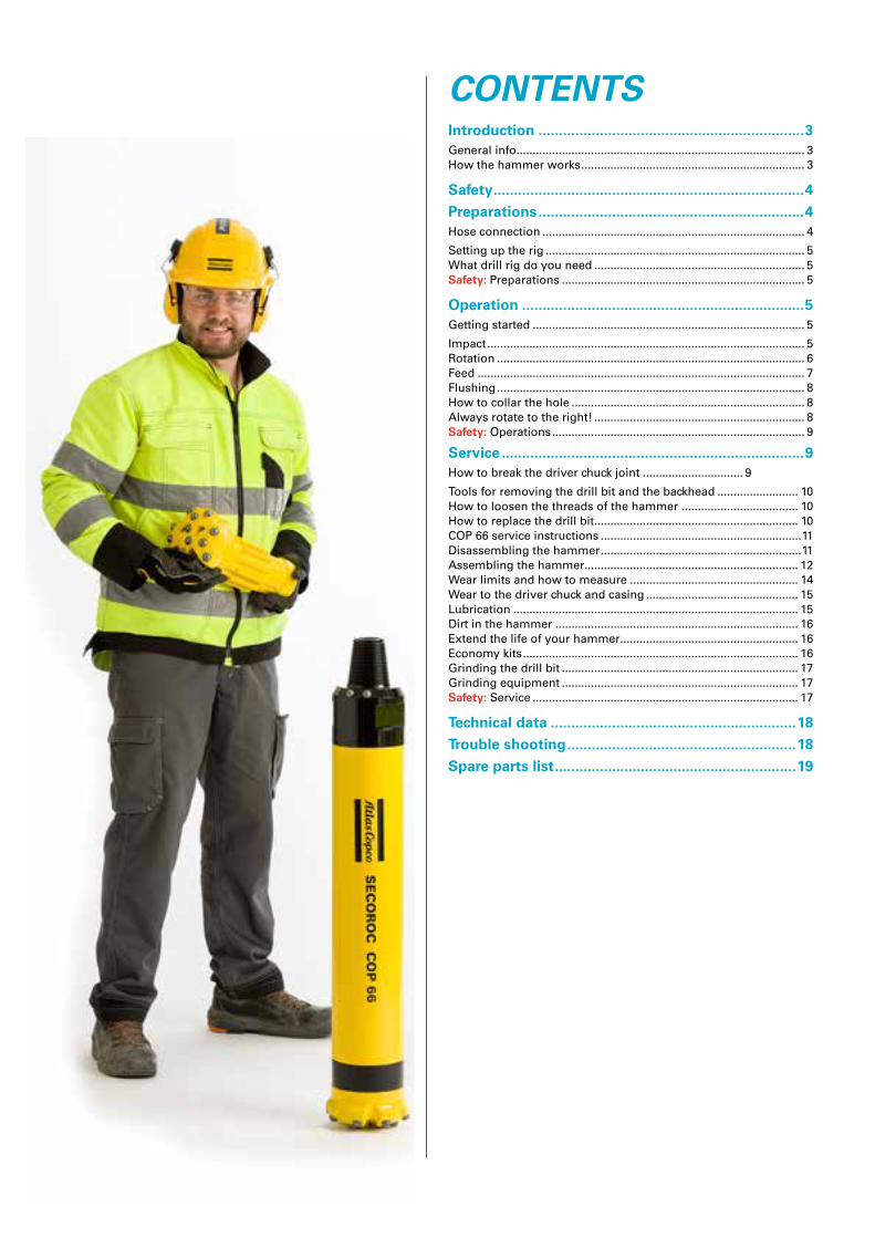
How the hammer worksThe Secoroc COP 66 down-the-hole hammer and drill bit oper- ate at the bottom of the hole as a unit.
A driver chuck (1) threads into the front end of the casing (7).
The splined union between the driver chuck and drill bit (2)
transmits rotation to the drill bit. The front end of the driver chuck transmits feed force to the drill bit. The split stop ring (3) limits axial movement of the drill bit. The check valve (8) prevents water from entering the hammer through the drill bit when the com-pressed air supply is shut off.
When feed force is applied, the drill bit is pushed into the
hammer and pressed against the front of the driver chuck. The impact piston (5) strikes the shank of the drill bit directly. The passage of compressed air through the hammer is directed by the piston, control tube (6) and bit bushing (4), which all have regulat-ing ducts. A built-in damping chamber cushions the piston return stroke and increases the impact frequency.
After the compressed air has imparted most of its pressure
energy to the piston, it is led as exhaust air through airchannels on the splines of drill bit and chuck. The exhaust air then emerges as flushing air through holes in the drill bit head. This gives ef-ficient transportation of cuttings out of the drill hole
When the hammer is lifted off the bottom of the hole, the piston drops into the air blowing position. This disengages percussion and gives air blowing only, that is, a large volume of air flows straight through the hammer and drill bit. During drilling, air blowing starts if the drill bit loses contact with the bottom of the hole. The hammer starts operating again as soon as the bit is pressed back against the driver chuck. Air blowing is used when powerful flushing of the drill hole is required, and in certain dif-ficult drilling conditions.
Friction between the drill pipes and the hole wall can some times reduce the penetration rate. This can often be counteracted by increasing the air pressure to give more impact power and faster penetration.
8
7
6
5
4
3
2
1
4
SAFETYGeneral safety regulations• Before starting, read these instructions carefully and follow the pieces of advice that are given.
• Use only authorized parts. Any damage or malfunction caused by the use of unauthorized parts is not covered by Warranty or Product Liability.
• Make sure that all warning signs on the rig remain in place and are free from dirt and easily legible.
• Make sure there are no personnel inside the working area of the drill rig during drilling, or when moving the rig.
• Always wear a helmet, goggles and ear protectors during drill-ing. Also observe any local regulations.
• The exhaust air from air driven hammers and grinding machines contains oil. It can be dangerous to inhale oil mist. Adjust the lubricator so that the correct rate of lubrication is obtained.
• Make sure that the place of work is well ventilated.
• Always check that hoses, hose nipples and hose clamps are properly tightened and secured, and that they are not damaged. Hoses that come loose can cause serious injury.
• Local regulations concerning air hoses and connections must always be strictly observed. This is especially the case if the DTH- hammer is to be operated at pressures above 10 bar (145 psi).
• The machine must not be used for purposes other than those prescribed by Secoroc (that is mining, quarrying, civil-engineer-ing, deep hole, water well and geothermal drilling operations).
Warning symbols
Indicates immediate hazards which WILL result in serious or fatal injury if the warning is not observed.
DANGER
Indicates hazards or hazardous procedures which COULD result in serious or fatal injury if the warning is not observed.
WARNING
Indicates hazards or hazardous procedures which COULD result in injury or damage to equipment if the warning is not observed.
CAUTION
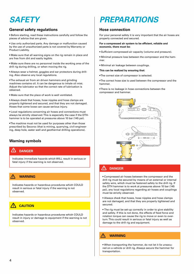
PREPARATIONSHose connectionFor your personal safety it is very important that the air hoses are properly connected and secured.
For a compressed air system to be efficient, reliable and economic, there must be:
• Sufficient compressed-air capacity (volume and pressure).
• Minimal pressure loss between the compressor and the ham-mer.
• Minimal air leakage between couplings.
This can be realized by ensuring that:
• The correct size of compressor is selected.
• The correct hose size is used between the compressor and the hammer.
• There is no leakage in hose connections between the compressor and hammer.
• Compressed air hoses between the compressor and the drill rig must be secured by means of an external or internal safety wire, which must be fastened safely to the drill rig. If the DTH hammer is to work at pressures above 10 bar (145 psi), any local regulations regarding air hoses and couplings must be strictly observed.
• Always check that hoses, hose nipples and hose clamps are not damaged, and that they are properly tightened and secured.
• The rig must be set-up correctly in order to give stability and safety. If this is not done, the effects of feed force and rotation torque can cause the rig to move or even to over-turn. This could result in serious or fatal injury as well as damage to the drill rig and equipment.
DANGER
• When transporting the hammer, do not let it lie unsecu-red on a vehicle or drill rig. Always secure the hammer for transportation.
WARNING
5
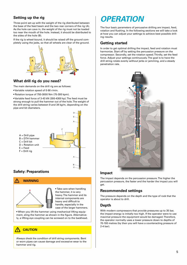
OPERATIONThe four basic parameters of percussive drilling are impact, feed, rotation and flushing. In the following sections we will take a look at how you can adjust your settings to achieve best possible drill-ing results.
Getting startedIn order to get optimal drilling the impact, feed and rotation must harmonize. Start off by setting the percussion pressure on the compressor. Secondly, set the rotation speed. Thirdly, set the feed force. Adjust your settings continuously. The goal is to have the drill string rotate evenly without jerks or jamming, and a steady penetration rate.
TONS
ImpactThe impact depends on the percussion pressure. The higher the percussion pressure, the faster and the harder the impact you will get.
Recommended settingsThe pressure depends on the depth and the type of rock that the operator is about to drill.
DepthWith modern compressors that provide pressures up to 35 bar, the impact energy is initially too high. If the operator were to use maximal pressure the equipment would be damaged. Therefore, the operator normally uses a lower pressure down to depths of 70-100 metres (by then you will have a counteracting pressure of 2-4 bar).
Setting up the rigThree-point set-up with the weight of the rig distributed between the base of the feed beam and the two rear corners of the rig (A). As the hole can cave in, the weight of the rig must not be loaded too near the mouth of the hole. Instead, it should be distributed to the sides of the hole (B).
If the rig is wheel-bound, it should be raised off the ground com-pletely using the jacks, so that all wheels are clear of the ground.
A B
What drill rig do you need?The main demands on the drill rig are as follows:
• Variable rotation speed of 0-90 r/min.
• Rotation torque of 750-3000 Nm (75-300 kpm).
• Variable feed force of 3-43 kN (300-4300 kp). The feed must be strong enough to pull the hammer out of the hole. The weight of the drill string varies between 9 and 34 kg/m, depending on the pipe and bit diameters.
A = Drill pipe B = DTH hammer C = Drill bit D = Rotation unit E = Feed F = Drill rig
Safety: Preparations
• Take care when handling the hammer, it is very heavy. The hammer and its internal components are heavy and difficult to handle, especially in the case of the larger hammers.
• When you lift the hammer using mechanical lifting equip-ment, sling the hammer as shown in the figure. Alternative-ly, a lifting-eye coupling can be screwed on to the backhead.
WARNING
•
Always check the condition of drill string components. Bent or worn pipes can cause damage and excessive wear to the hammer and rig.
CAUTION
6
bit diameter * 3,14 πRPM =
strokes per minute * button diameter
+/- 15% depending on rock formation or drill bit design
Exercise:
Suppose you are drilling at 25 bar with a COP 66 hammer. Your bit size is 165 mm and the bit button diameter is 16 mm. What is the recommended starting point for the rotation speed?
Answer:
A COP 66 hammer at 25 bar provides 2160 strokes per minute.
RPM = (2160*16) / (165*3,14) = 67 Rpm revolutions/min
B: 300 divided by the bit diameter
You could get a very rough estimate of the RPM simply by divid-ing 300 by the bit diameter in inches.
Exercise:
Suppose you are drilling with a 6 inch hammer (a 152 mmm hole). What is the recoomended starting point for the rotation speed?
Answer:
RPM = 300/6 = 50 rotations/min
C: Use a piece of chalk
The idea is to set the rotation speed based on the penetration rate. Follow the instructions given below.
1) Grab a piece of chalk or a soapstone.
2) Scribe a spiral on the drill pipe while the drill is operating.
3) Measure the distance between the spirals. If the space is less than 10 mm the drill RPM should be decreased. If the space is more than 20 mm the drill RPM should be increased. Having adjusted the settings, repeat the procedure until the space is between 10 mm and 19 mm.
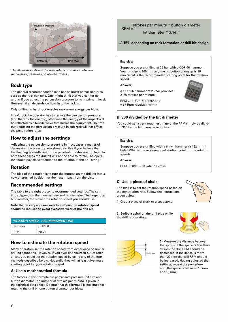
The illustration shows the principled correlation between percussion pressure and rock hardness.
Rock typeThe general recommendation is to use as much percussion pres-sure as the rock can take. One might think that you cannot go wrong if you adjust the percussion pressure to its maximum level. However, it all depends on how hard the rock is.
Only drilling in hard rock enables maximum energy per blow.
In soft rock the operator has to reduce the percussion pressure (and thereby the energy), otherwise the energy of the impact will be reflected as a tensile wave that harms the equipment. Do note that reducing the percussion pressure in soft rock will not affect the penetration rates.
How to adjust the setttingsAdjusting the percussion pressure is in most cases a matter of decreasing the pressure. You should do this if you believe that the flushing is insufficient or the penetration rates are too high. In both these cases the drill bit will not be able to rotate. The opera-tor should pay close attention to the rotation of the drill string.
RotationThe idea of the rotation is to turn the buttons on the drill bit into a new uncrushed position for the next impact from the piston.
Recommended settingsThe table to the right presents recommended settings. The set-tings depend on the hammer size and bit diameter. The larger the bit diameter, the slower the rotation speed you should use.
Note that in very abrasive rock formations the rotation speed should be reduced to avoid excessive wear of the drill bit�
ROTATION SPEED - RECOMMENDATIONS
Hammer COP 66
RPM1 20-70
How to estimate the rotation speedMany operators set the rotation speed from experience of similar drilling situations. However, if you ever find yourself out of refer-ences, you could set the rotation speed by using any of the four methods described below. Hopefully they will at least give you a starting point for your rotation speed.
A: Use a mathematical formula
The factors in this formula are percussive pressure, bit size and button diameter. The number of strokes per minute is given in the technical data sheet. Do note that this formula is designed for rotating the drill bit one button diameter per blow.
7
D: Uneven wear on drill bit buttons
Look out for uneven wear on the carbide buttons.
Comments: The four methods for setting the rotation speed all give different results. Method A normally suggest the highest RPM, method B the second highest value, method C the second lowest value and method D the lowest RPM. Please follow the instructions below for how to adjust the settings for best results.
How to adjust the settingsDecrease the rotation speed if you notice:
• Increased wear to the drill bit, the hammer and the drill pipes
• Increased stresses to the feed and rotation unit
Increase the rotation speed if you notice:
• Poor drilling output
• Uneven rotation
• Uneven wear on buttons
FeedThe purpose of the feed is to keep the shank of the drill bit pressed into the hammer while drilling.
Recommended settings
The feed force often needs to be corrected during drilling, de-pending on the rock formation and the weight of the drill string. The deeper the hole the less feed force is required, as the drill string gets heavier. In very deep holes the drill string is actually being held up to compensate for the heavy string. This is called “negative feeding” or “a holdback function”.
A rough guide to drill pipe weights for different sizes of DTH- hammer are given in the table.
Too low a feed force could harm the equipment.
A tip for finding the setting force is to increase the feed force until the bit is having a hard time to rotate, then you should cut down the feed force until the bit rotates smoothly.
RECOMMENDED FEED FORCE
Air pressure (bar) Feed force (kN) Feed force (lbs)
10 7 1570
15 10 2250
20 14 3150
25 17 3820
30 20 4500
Pipe dimension, mm Approx� weight, kg/m
76 9
89 15
102 18
114 20
127 23
140 34
How to adjust the settingsDecrease the feed force if you notice:
• Rotation is jerky, uneven or completely stopped
• Hole deviation
• The rig is unstable and repositioned
If you carry on drilling with a feed force that is too high you will experi- ence reduced capacity. You will also expose the drill string to severe bending stresses and possibly harm the rotation unit and feed beam.
Increase the feed force if you notice:
• Vibrations
• Poor drilling results
• Increased wear to splines (The splines are the steel channels in-side the driver chuck that the bit shank holds on to while rotating).
If the feed force is not correctly set it will make the drill bit come out of rhythm in relation to the air cycle inside the hammer. This will increase the wear on the hammer.
Observing the drill string is the key to correctly adjusting the feed force. Aim for a constant, even rotation speed with no jamming and a steady penetration.
FlushingIf the cuttings are not removed, the drill bit will re-crush already crushed material. This is a waste of energy and will reduce the capacity of the drill. Flushing media are air, water and foam.
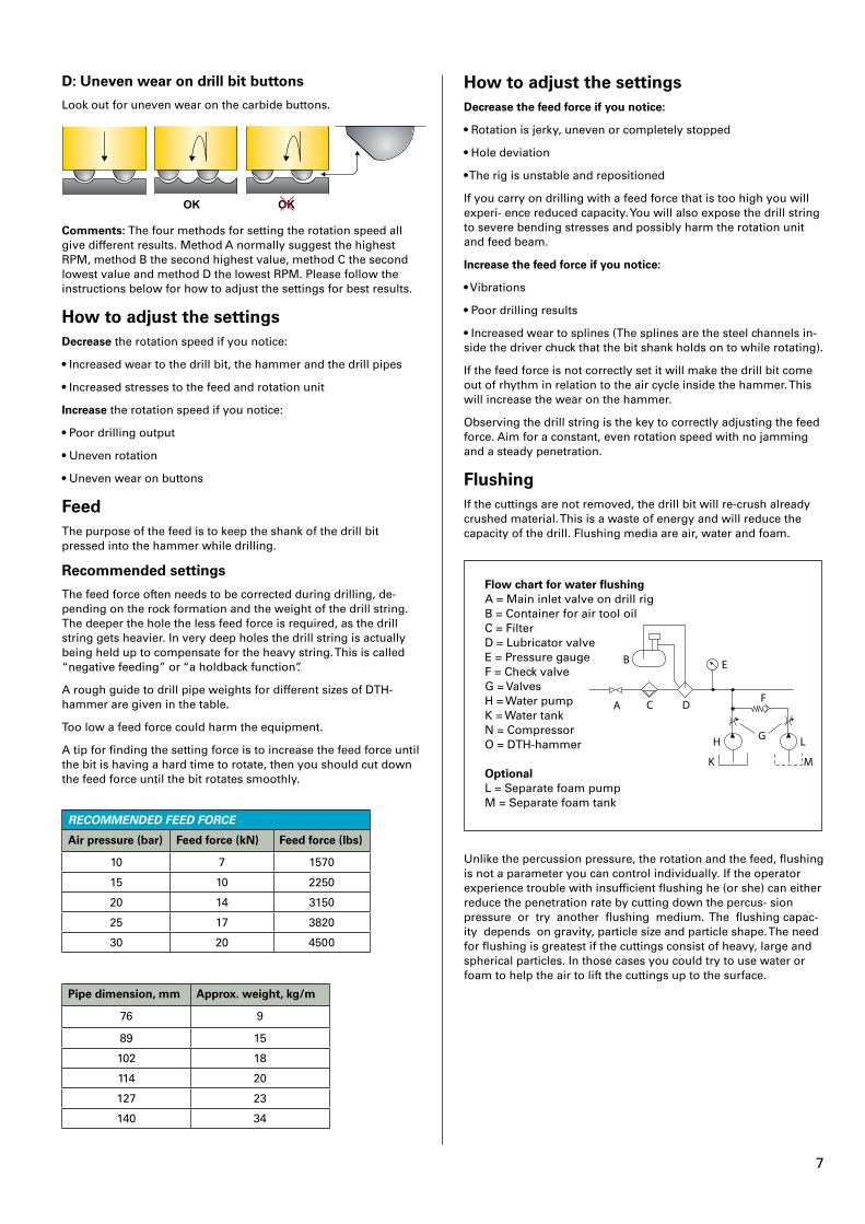
Flow chart for water flushingA = Main inlet valve on drill rig B = Container for air tool oilC = FilterD = Lubricator valve E = Pressure gauge F = Check valveG = Valves H = Water pumpK = Water tankN = Compressor O = DTH-hammer
OptionalL = Separate foam pump M = Separate foam tank
Unlike the percussion pressure, the rotation and the feed, flushing is not a parameter you can control individually. If the operator experience trouble with insufficient flushing he (or she) can either reduce the penetration rate by cutting down the percus- sion pressure or try another flushing medium. The flushing capac-ity depends on gravity, particle size and particle shape. The need for flushing is greatest if the cuttings consist of heavy, large and spherical particles. In those cases you could try to use water or foam to help the air to lift the cuttings up to the surface.
8
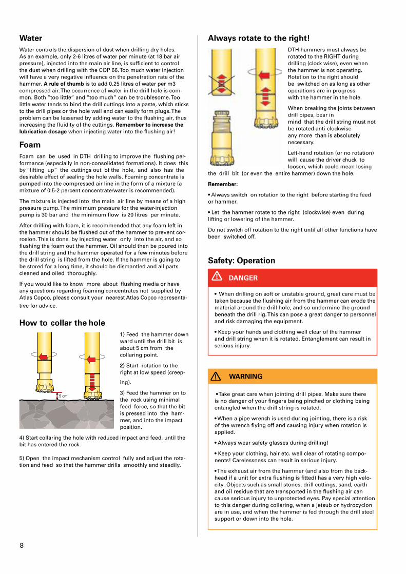
Always rotate to the right!DTH hammers must always be rotated to the RIGHT during drilling (clock wise), even when the hammer is not operating. Rotation to the right should be switched on as long as other operations are in progress with the hammer in the hole.
When breaking the joints between drill pipes, bear in mind that the drill string must not be rotated anti -clockwise any more than is absolutely necessary.
Left-hand rotation (or no rotation) will cause the driver chuck to loosen, which could mean losing
the drill bit (or even the entire hammer) down the hole.
Remember:
• Always switch on rotation to the right before starting the feed or hammer.
• Let the hammer rotate to the right (clockwise) even during lifting or lowering of the hammer.
Do not switch off rotation to the right until all other functions have been switched off.
Safety: Operation
• When drilling on soft or unstable ground, great care must be taken because the flushing air from the hammer can erode the material around the drill hole, and so undermine the ground beneath the drill rig. This can pose a great danger to personnel and risk damaging the equipment.
• Keep your hands and clothing well clear of the hammer and drill string when it is rotated. Entanglement can result in serious injury.
DANGER
• Take great care when jointing drill pipes. Make sure there is no danger of your fingers being pinched or clothing being entangled when the drill string is rotated.
• When a pipe wrench is used during jointing, there is a risk of the wrench fiying off and causing injury when rotation is applied.
• Always wear safety glasses during drilling!
• Keep your clothing, hair etc. well clear of rotating compo-nents! Careless ness can result in serious injury.
• The exhaust air from the hammer (and also from the back-head if a unit for extra fiushing is fitted) has a very high velo-city. Objects such as small stones, drill cuttings, sand, earth and oil residue that are transported in the flushing air can cause serious injury to unprotected eyes. Pay special attention to this danger during collaring, when a jetsub or hydrocyclon are in use, and when the hammer is fed through the drill steel support or down into the hole.
WARNING
WaterWater controls the dispersion of dust when drilling dry holes. As an example, only 2-6 litres of water per minute (at 18 bar air pressure), injected into the main air line, is sufficient to control the dust when drilling with the COP 66. Too much water injection will have a very negative influence on the penetration rate of the hammer. A rule of thumb is to add 0.25 litres of water per m3 compressed air. The occurrence of water in the drill hole is com-mon. Both “too little” and “too much” can be troublesome. Too little water tends to bind the drill cuttings into a paste, which sticks to the drill pipes or the hole wall and can easily form plugs. The problem can be lessened by adding water to the flushing air, thus increasing the fluidity of the cuttings. Remember to increase the lubrication dosage when injecting water into the flushing air!
FoamFoam can be used in DTH drilling to improve the flushing per-formance (especially in non-consolidated formations). It does this by “lifting up” the cuttings out of the hole, and also has the desirable effect of sealing the hole walls. Foaming concentrate is pumped into the compressed air line in the form of a mixture (a mixture of 0.5-2 percent concentrate/water is recommended).
The mixture is injected into the main air line by means of a high pressure pump. The minimum pressure for the water-injection pump is 30 bar and the minimum flow is 20 litres per minute.
After drilling with foam, it is recommended that any foam left in the hammer should be flushed out of the hammer to prevent cor-rosion. This is done by injecting water only into the air, and so flushing the foam out the hammer. Oil should then be poured into the drill string and the hammer operated for a few minutes before the drill string is lifted from the hole. If the hammer is going to be stored for a long time, it should be dismantled and all parts cleaned and oiled thoroughly.
If you would like to know more about flushing media or have any questions regarding foaming concentrates not supplied by Atlas Copco, please consult your nearest Atlas Copco representa-
tive for advice.
How to collar the hole
5 cm
1) Feed the hammer down ward until the drill bit is about 5 cm from the collar ing point.
2) Start rotation to the right at low speed (creep-
ing).
3) Feed the hammer on to the rock using minimal feed force, so that the bit is pressed into the ham-mer, and into the impact position.
4) Start collaring the hole with reduced impact and feed, until the bit has entered the rock. 5) Open the impact mechanism control fully and adjust the rota-tion and feed so that the hammer drills smoothly and steadily.
9
• Always wear ear protectors during drilling.
• The injection point for water and foaming concentrate should always be located after the main shut-off valve on the rig. If not, there is a danger of the mixture being pumped back through the main air line and into the compressor. This could seriously damage the compressor.
CAUTION
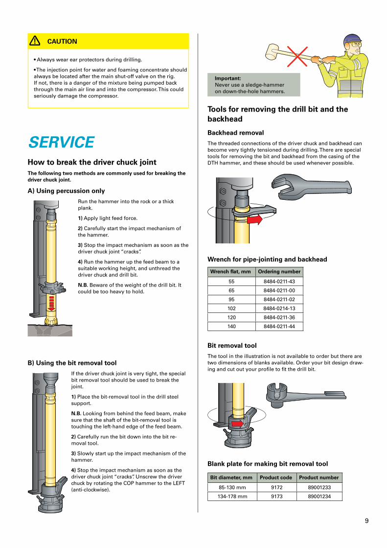
SERVICEHow to break the driver chuck jointThe following two methods are commonly used for breaking the driver chuck joint�
A) Using percussion only
Run the hammer into the rock or a thick plank.
1) Apply light feed force.
2) Carefully start the impact mechanism of the hammer.
3) Stop the impact mechanism as soon as the driver chuck joint “cracks”.
4) Run the hammer up the feed beam to a suitable working height, and unthread the driver chuck and drill bit.
N�B� Beware of the weight of the drill bit. It could be too heavy to hold.
B) Using the bit removal tool
If the driver chuck joint is very tight, the special bit removal tool should be used to break the joint.
1) Place the bit-removal tool in the drill steel support.
N�B� Looking from behind the feed beam, make sure that the shaft of the bit-removal tool is touching the left-hand edge of the feed beam.
2) Carefully run the bit down into the bit re-moval tool.
3) Slowly start up the impact mechanism of the hammer.
4) Stop the impact mechanism as soon as the driver chuck joint “cracks”. Unscrew the driver chuck by rotating the COP hammer to the LEFT (anti-clockwise).
Important: Never use a sledge-hammer on down-the-hole hammers.
Tools for removing the drill bit and the backhead
Backhead removal
The threaded connections of the driver chuck and backhead can become very tightly tensioned during drilling. There are special tools for removing the bit and backhead from the casing of the DTH hammer, and these should be used whenever possible.
Wrench for pipe-jointing and backhead
Wrench flat, mm Ordering number
55 8484-0211-43
65 8484-0211-00
95 8484-0211-02
102 8484-0214-13
120 8484-0211-36
140 8484-0211-44
Bit removal tool
The tool in the illustration is not available to order but there are two dimensions of blanks available. Order your bit design draw-ing and cut out your profile to fit the drill bit.
Blank plate for making bit removal tool
Bit diameter, mm Product code Product number
85-130 mm 9172 89001233
134-178 mm 9173 89001234
10
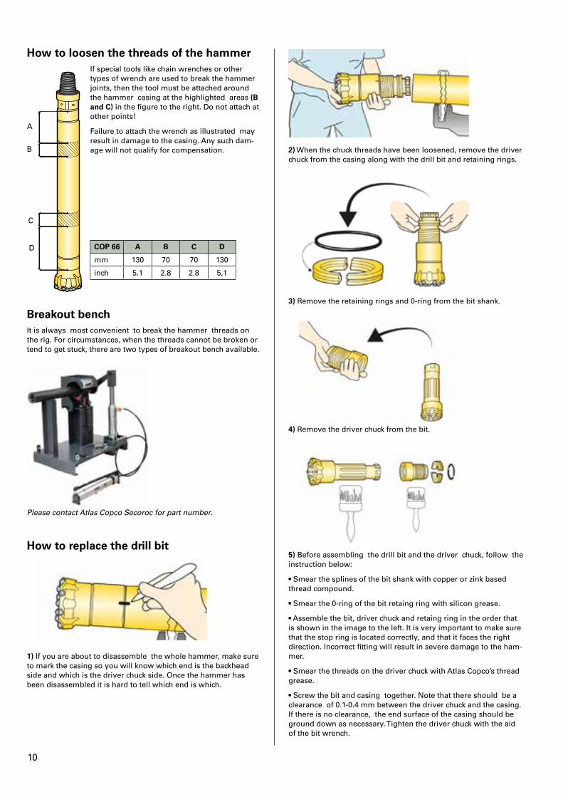
How to loosen the threads of the hammer
A
B
C
D
If special tools like chain wrenches or other types of wrench are used to break the hammer joints, then the tool must be attached around the hammer casing at the highlighted areas (B and C) in the figure to the right. Do not attach at other points!
Failure to attach the wrench as illustrated may result in damage to the casing. Any such dam-age will not qualify for compensation.
COP 66 A B C D
mm 130 70 70 130
inch 5.1 2.8 2.8 5,1
Breakout benchIt is always most convenient to break the hammer threads on the rig. For circumstances, when the threads cannot be broken or tend to get stuck, there are two types of breakout bench available.
Please contact Atlas Copco Secoroc for part number.
How to replace the drill bit
1) If you are about to disassemble the whole hammer, make sure to mark the casing so you will know which end is the backhead side and which is the driver chuck side. Once the hammer has been disassembled it is hard to tell which end is which.
2) When the chuck threads have been loosened, remove the driver chuck from the casing along with the drill bit and retaining rings.
3) Remove the retaining rings and 0-ring from the bit shank.
4) Remove the driver chuck from the bit.
5) Before assembling the drill bit and the driver chuck, follow the instruction below:
• Smear the splines of the bit shank with copper or zink based thread compound.
• Smear the 0-ring of the bit retaing ring with silicon grease.
• Assemble the bit, driver chuck and retaing ring in the order that is shown in the image to the left. It is very important to make sure that the stop ring is located correctly, and that it faces the right direc tion. Incorrect fitting will result in severe damage to the ham-mer.
• Smear the threads on the driver chuck with Atlas Copco’s thread grease.
• Screw the bit and casing together. Note that there should be a clearance of 0.1-0.4 mm between the driver chuck and the casing. If there is no clearance, the end surface of the casing should be ground down as necessary. Tighten the driver chuck with the aid of the bit wrench.
11
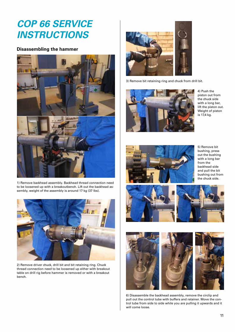
COP 66 SERVICE INSTRUCTIONSDisassembling the hammer
1) Remove backhead assembly. Backhead thread connection need to be loosened up with a breakoutbench. Lift out the backhead as-sembly, weight of the assembly is around 17 kg (37 lbs).
2) Remove driver chuck, drill bit and bit retaining ring. Chuck thread connection need to be loosened up either with breakout table on drill rig before hammer is removed or with a breakout bench.
3) Remove bit retaining ring and chuck from drill bit.
4) Push the piston out from the chuck side with a long bar, lift the piston out. Weight of piston is 17,4 kg.
5) Remove bit bushing, press out the bushing with a long bar from the backhead side and pull the bit bushing out from the chuck side.
6) Disassemble the backhead assembly, remove the circlip and pull out the control tube with buffers and retainer. Move the con-trol tube from side to side while you are pulling it upwards and it will come loose.
12
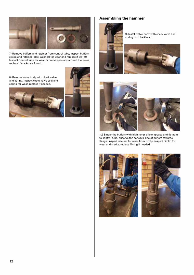
7) Remove buffers and retainer from control tube, Inspect buffers, circlip and retainer (steel washer) for wear and replace if worn!! Inspect Control tube for wear or cracks specially around the holes, replace if cracks are found.
8) Remove Valve body with check valve and spring. Inspect check valve seal and spring for wear, replace if needed.
Assembling the hammer
9) Install valve body with check valve and spring in to backhead.
10) Smear the buffers with high temp silicon grease and fit them to control tube, observe the concave side of buffers towards flange, Inspect retainer for wear from circlip, inspect circlip for wear and cracks, replace O-ring if needed.
13
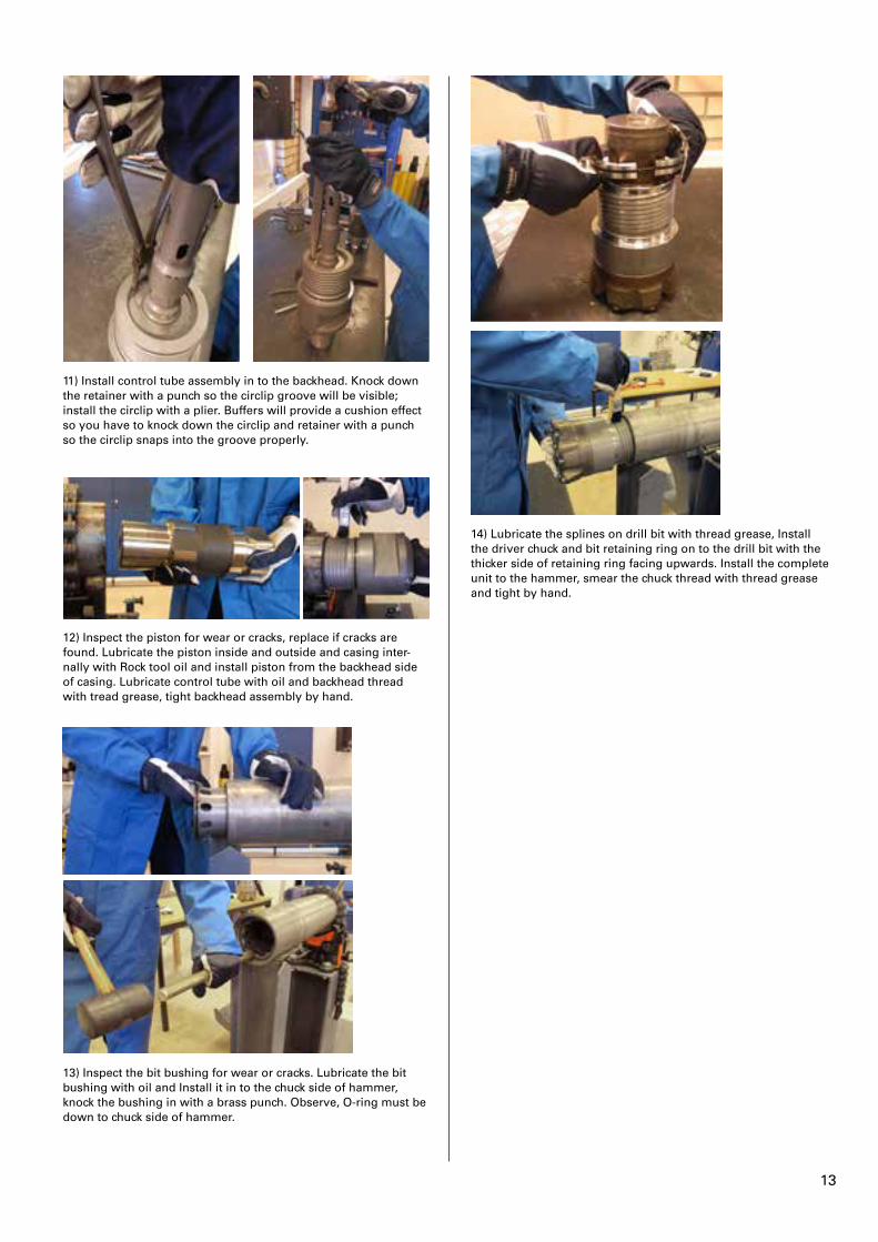
11) Install control tube assembly in to the backhead. Knock down the retainer with a punch so the circlip groove will be visible; install the circlip with a plier. Buffers will provide a cushion effect so you have to knock down the circlip and retainer with a punch so the circlip snaps into the groove properly.
12) Inspect the piston for wear or cracks, replace if cracks are found. Lubricate the piston inside and outside and casing inter-nally with Rock tool oil and install piston from the backhead side of casing. Lubricate control tube with oil and backhead thread with tread grease, tight backhead assembly by hand.
13) Inspect the bit bushing for wear or cracks. Lubricate the bit bushing with oil and Install it in to the chuck side of hammer, knock the bushing in with a brass punch. Observe, O-ring must be down to chuck side of hammer.
14) Lubricate the splines on drill bit with thread grease, Install the driver chuck and bit retaining ring on to the drill bit with the thicker side of retaining ring facing upwards. Install the complete unit to the hammer, smear the chuck thread with thread grease and tight by hand.
14
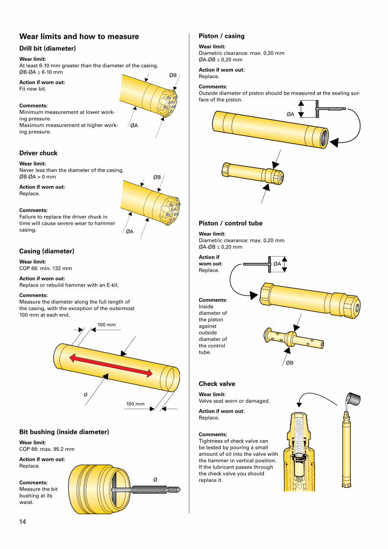
Wear limits and how to measureDrill bit (diameter)
Wear limit:At least 6-10 mm greater than the diameter of the casing. ØB-ØA ≥ 6-10 mm
Action if worn out:Fit new bit.
ØB
ØA
Comments:Minimum measurement at lower work-ing pressure. Maximum measurement at higher work-ing pressure.
Driver chuck
Wear limit:Never less than the diameter of the casing. ØB-ØA > 0 mm
Action if worn out:Replace.
ØB
ØA
Comments:Failure to replace the driver chuck in time will cause severe wear to hammer casing.
Casing (diameter)
Wear limit:COP 66: min. 132 mm
Action if worn out:Replace or rebuild hammer with an E-kit.
Comments:Measure the diameter along the full length of the casing, with the exception of the outermost 100 mm at each end.
100 mm
100 mm
Ø
Bit bushing (inside diameter)
Wear limit:COP 66: max. 95.2 mm
Action if worn out:Replace.
ØComments:Measure the bit bushing at its waist.
Piston / casing
Wear limit:Diametric clearance: max. 0,20 mm ØA-ØB ≤ 0,20 mm
Action if worn out:Replace.
Comments:Outside diameter of piston should be measured at the sealing sur- face of the piston.
ØA
Piston / control tube
Wear limit:Diametric clearance: max. 0,20 mm ØA-ØB ≤ 0,20 mm
Action if worn out:Replace.
ØA
ØB
Comments:Inside diameter of the piston against outside diameter of the control tube.
Check valve
Wear limit:Valve seat worn or damaged.
Action if worn out:Replace.
Comments:Tightness of check valve can be tested by pouring a small amount of oil into the valve with the hammer in vertical position. If the lubricant passes through the check valve you should replace it.
15
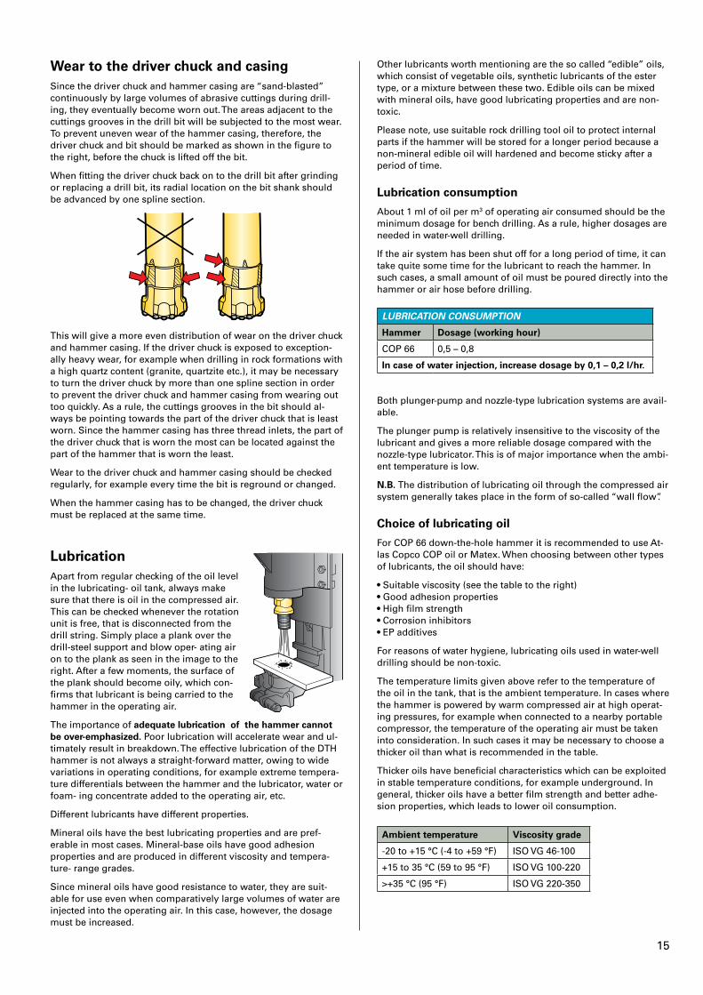
Wear to the driver chuck and casingSince the driver chuck and hammer casing are “sand-blasted” continuously by large volumes of abrasive cuttings during drill-ing, they eventually become worn out. The areas adjacent to the cuttings grooves in the drill bit will be subjected to the most wear. To prevent uneven wear of the hammer casing, therefore, the driver chuck and bit should be marked as shown in the figure to the right, before the chuck is lifted off the bit.
When fitting the driver chuck back on to the drill bit after grinding or replacing a drill bit, its radial location on the bit shank should be advanced by one spline section.
This will give a more even distribution of wear on the driver chuck and hammer casing. If the driver chuck is exposed to exception-ally heavy wear, for example when drilling in rock formations with a high quartz content (granite, quartzite etc.), it may be necessary to turn the driver chuck by more than one spline section in order to prevent the driver chuck and hammer casing from wearing out too quickly. As a rule, the cuttings grooves in the bit should al-ways be pointing towards the part of the driver chuck that is least worn. Since the hammer casing has three thread inlets, the part of the driver chuck that is worn the most can be located against the part of the hammer that is worn the least.
Wear to the driver chuck and hammer casing should be checked regularly, for example every time the bit is reground or changed.
When the hammer casing has to be changed, the driver chuck must be replaced at the same time.
LubricationApart from regular checking of the oil level in the lubricating- oil tank, always make sure that there is oil in the compressed air. This can be checked whenever the rotation unit is free, that is disconnected from the drill string. Simply place a plank over the drill-steel support and blow oper- ating air on to the plank as seen in the image to the right. After a few moments, the surface of the plank should become oily, which con-firms that lubricant is being carried to the hammer in the operating air.
The importance of adequate lubrication of the hammer cannot be over-emphasized� Poor lubrication will accelerate wear and ul-timately result in breakdown. The effective lubrication of the DTH hammer is not always a straight-forward matter, owing to wide variations in operating conditions, for example extreme tempera-ture differentials between the hammer and the lubricator, water or foam- ing concentrate added to the operating air, etc.
Different lubricants have different properties.
Mineral oils have the best lubricating properties and are pref-erable in most cases. Mineral-base oils have good adhesion properties and are produced in different viscosity and tempera-ture- range grades.
Since mineral oils have good resistance to water, they are suit- able for use even when comparatively large volumes of water are injected into the operating air. In this case, however, the dosage must be increased.
Other lubricants worth mentioning are the so called “edible” oils, which consist of vegetable oils, synthetic lubricants of the ester type, or a mixture between these two. Edible oils can be mixed with mineral oils, have good lubricating properties and are non-toxic.
Please note, use suitable rock drilling tool oil to protect internal parts if the hammer will be stored for a longer period because a non-mineral edible oil will hardened and become sticky after a period of time.
Lubrication consumption
About 1 ml of oil per m3 of operating air consumed should be the minimum dosage for bench drilling. As a rule, higher dosages are needed in water-well drilling.
If the air system has been shut off for a long period of time, it can take quite some time for the lubricant to reach the hammer. In such cases, a small amount of oil must be poured directly into the hammer or air hose before drilling.
LUBRICATION CONSUMPTION
Hammer Dosage (working hour)
COP 66 0,5 – 0,8
In case of water injection, increase dosage by 0,1 – 0,2 l/hr�
Both plunger-pump and nozzle-type lubrication systems are avail-able.
The plunger pump is relatively insensitive to the viscosity of the lubricant and gives a more reliable dosage compared with the nozzle-type lubricator. This is of major importance when the ambi-ent temperature is low.
N�B� The distribution of lubricating oil through the compressed air system generally takes place in the form of so-called “wall flow”.
Choice of lubricating oil
For COP 66 down-the-hole hammer it is recommended to use At-las Copco COP oil or Matex. When choosing between other types of lubricants, the oil should have:
• Suitable viscosity (see the table to the right) • Good adhesion properties • High film strength • Corrosion inhibitors • EP additives
For reasons of water hygiene, lubricating oils used in water-well drilling should be non-toxic.
The temperature limits given above refer to the temperature of the oil in the tank, that is the ambient temperature. In cases where the hammer is powered by warm compressed air at high operat-ing pressures, for example when connected to a nearby portable compressor, the temperature of the operating air must be taken into consideration. In such cases it may be necessary to choose a thicker oil than what is recommended in the table.
Thicker oils have beneficial characteristics which can be exploited in stable temperature conditions, for example underground. In general, thicker oils have a better film strength and better adhe-sion properties, which leads to lower oil consumption.
Ambient temperature Viscosity grade
-20 to +15 °C (-4 to +59 °F) ISO VG 46-100
+15 to 35 °C (59 to 95 °F) ISO VG 100-220
>+35 °C (95 °F) ISO VG 220-350
16
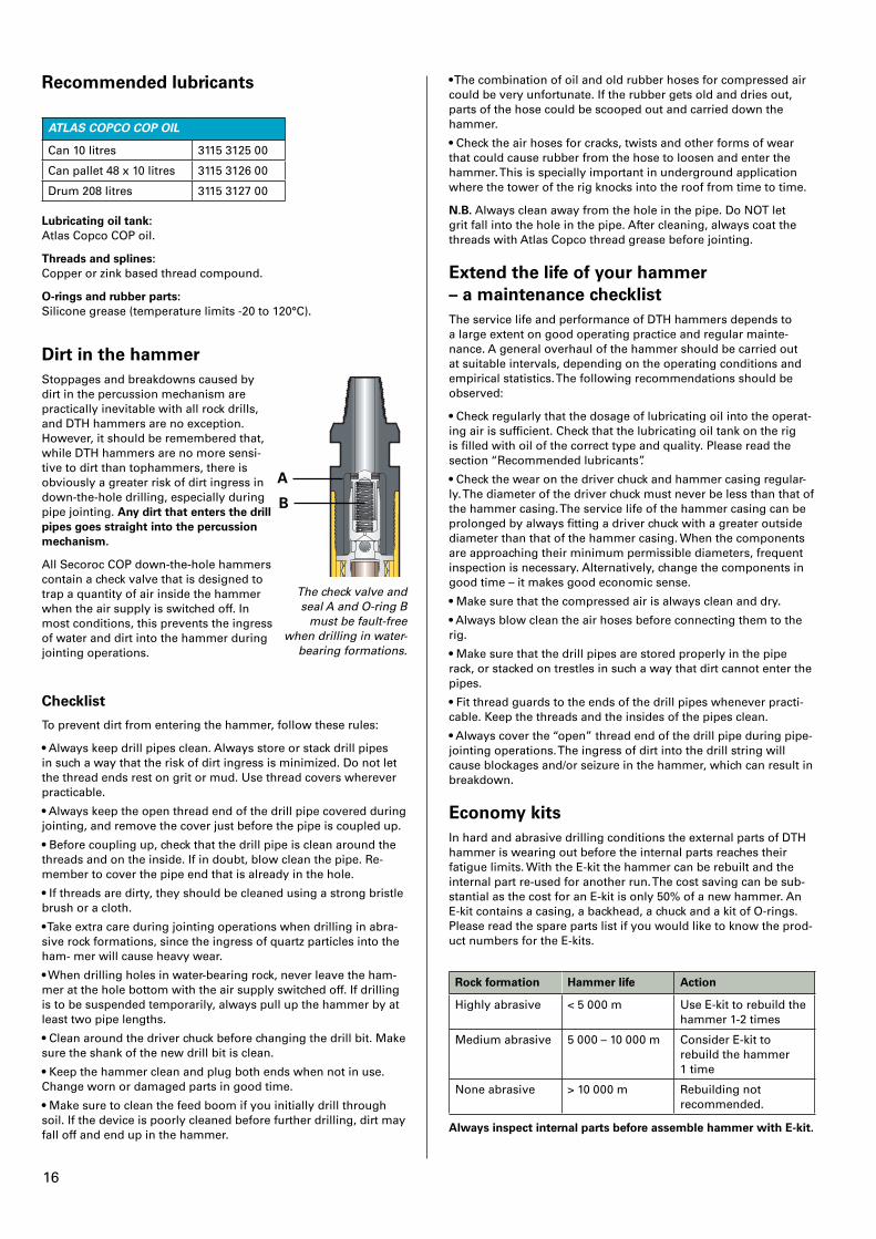
Recommended lubricants
ATLAS COPCO COP OIL
Can 10 litres 3115 3125 00
Can pallet 48 x 10 litres 3115 3126 00
Drum 208 litres 3115 3127 00
Lubricating oil tank:Atlas Copco COP oil.
Threads and splines:Copper or zink based thread compound.
O-rings and rubber parts:Silicone grease (temperature limits -20 to 120°C).
A
B
The check valve and seal A and O-ring B
must be fault-free when drilling in water-
bearing formations.
Dirt in the hammerStoppages and breakdowns caused by dirt in the percussion mechanism are practically inevitable with all rock drills, and DTH hammers are no exception. However, it should be remembered that, while DTH hammers are no more sensi-tive to dirt than tophammers, there is obviously a greater risk of dirt ingress in down-the-hole drilling, especially during pipe jointing. Any dirt that enters the drill pipes goes straight into the percussion mechanism�
All Secoroc COP down-the-hole hammers contain a check valve that is designed to trap a quantity of air inside the hammer when the air supply is switched off. In most conditions, this prevents the ingress of water and dirt into the hammer during jointing operations.
Checklist
To prevent dirt from entering the hammer, follow these rules:
• Always keep drill pipes clean. Always store or stack drill pipes in such a way that the risk of dirt ingress is minimized. Do not let the thread ends rest on grit or mud. Use thread covers wherever practicable.
• Always keep the open thread end of the drill pipe covered during jointing, and remove the cover just before the pipe is coupled up.
• Before coupling up, check that the drill pipe is clean around the threads and on the inside. If in doubt, blow clean the pipe. Re-member to cover the pipe end that is already in the hole.
• If threads are dirty, they should be cleaned using a strong bristle brush or a cloth.
• Take extra care during jointing operations when drilling in abra-sive rock formations, since the ingress of quartz particles into the ham- mer will cause heavy wear.
• When drilling holes in water-bearing rock, never leave the ham-mer at the hole bottom with the air supply switched off. If drilling is to be suspended temporarily, always pull up the hammer by at least two pipe lengths.
• Clean around the driver chuck before changing the drill bit. Make sure the shank of the new drill bit is clean.
• Keep the hammer clean and plug both ends when not in use. Change worn or damaged parts in good time.
• Make sure to clean the feed boom if you initially drill through soil. If the device is poorly cleaned before further drilling, dirt may fall off and end up in the hammer.
• The combination of oil and old rubber hoses for compressed air could be very unfortunate. If the rubber gets old and dries out, parts of the hose could be scooped out and carried down the hammer.
• Check the air hoses for cracks, twists and other forms of wear that could cause rubber from the hose to loosen and enter the hammer. This is specially important in underground application where the tower of the rig knocks into the roof from time to time.
N�B� Always clean away from the hole in the pipe. Do NOT let grit fall into the hole in the pipe. After cleaning, always coat the threads with Atlas Copco thread grease before jointing.
Extend the life of your hammer – a maintenance checklistThe service life and performance of DTH hammers depends to a large extent on good operating practice and regular mainte-nance. A general overhaul of the hammer should be carried out at suitable intervals, depending on the operating conditions and empirical statistics. The following recommendations should be observed:
• Check regularly that the dosage of lubricating oil into the operat-ing air is sufficient. Check that the lubricating oil tank on the rig is filled with oil of the correct type and quality. Please read the section “Recommended lubricants”.
• Check the wear on the driver chuck and hammer casing regular-ly. The diameter of the driver chuck must never be less than that of the hammer casing. The service life of the hammer casing can be prolonged by always fitting a driver chuck with a greater outside diameter than that of the hammer casing. When the components are approaching their minimum permissible diameters, frequent inspection is necessary. Alternatively, change the components in good time – it makes good economic sense.
• Make sure that the compressed air is always clean and dry.
• Always blow clean the air hoses before connecting them to the rig.
• Make sure that the drill pipes are stored properly in the pipe rack, or stacked on trestles in such a way that dirt cannot enter the pipes.
• Fit thread guards to the ends of the drill pipes whenever practi-cable. Keep the threads and the insides of the pipes clean.
• Always cover the “open” thread end of the drill pipe during pipe- jointing operations. The ingress of dirt into the drill string will cause blockages and/or seizure in the hammer, which can result in breakdown.
Economy kitsIn hard and abrasive drilling conditions the external parts of DTH hammer is wearing out before the internal parts reaches their fatigue limits. With the E-kit the hammer can be rebuilt and the internal part re-used for another run. The cost saving can be sub-stantial as the cost for an E-kit is only 50% of a new hammer. An E-kit contains a casing, a backhead, a chuck and a kit of O-rings. Please read the spare parts list if you would like to know the prod-uct numbers for the E-kits.
Rock formation Hammer life Action
Highly abrasive < 5 000 m Use E-kit to rebuild the hammer 1-2 times
Medium abrasive 5 000 – 10 000 m Consider E-kit to rebuild the hammer 1 time
None abrasive > 10 000 m Rebuilding not recommended.
Always inspect internal parts before assemble hammer with E-kit�
17
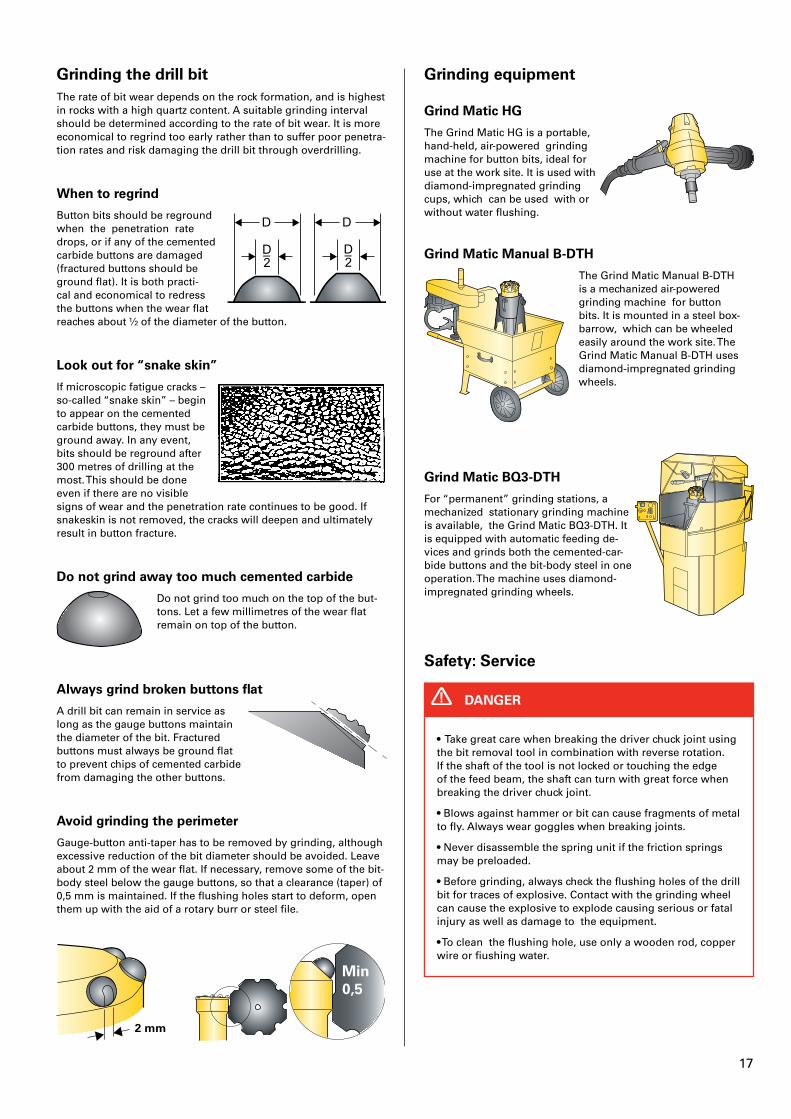
Grinding the drill bitThe rate of bit wear depends on the rock formation, and is highest in rocks with a high quartz content. A suitable grinding interval should be determined according to the rate of bit wear. It is more economical to regrind too early rather than to suffer poor penetra-tion rates and risk damaging the drill bit through overdrilling.
When to regrind
Button bits should be reground when the penetration rate drops, or if any of the cemented carbide buttons are damaged (fractured buttons should be ground flat). It is both practi-cal and economical to redress the buttons when the wear flat reaches about ½ of the diameter of the button.
Look out for “snake skin”
If microscopic fatigue cracks – so-called “snake skin” – begin to appear on the cemented carbide buttons, they must be ground away. In any event, bits should be reground after 300 metres of drilling at the most. This should be done even if there are no visible signs of wear and the penetration rate continues to be good. If snakeskin is not removed, the cracks will deepen and ultimately result in button fracture.
Do not grind away too much cemented carbide
Do not grind too much on the top of the but-tons. Let a few millimetres of the wear flat remain on top of the button.
Always grind broken buttons flat
A drill bit can remain in service as long as the gauge buttons maintain the diameter of the bit. Fractured buttons must always be ground flat to prevent chips of cemented carbide from damaging the other buttons.
Avoid grinding the perimeter
Gauge-button anti-taper has to be removed by grinding, although excessive reduction of the bit diameter should be avoided. Leave about 2 mm of the wear flat. If necessary, remove some of the bit- body steel below the gauge buttons, so that a clearance (taper) of 0,5 mm is maintained. If the flushing holes start to deform, open them up with the aid of a rotary burr or steel file.
2 mm
Min 0,5
Grinding equipment
Grind Matic HG
The Grind Matic HG is a portable, hand-held, air-powered grinding machine for button bits, ideal for use at the work site. It is used with diamond-impregnated grinding cups, which can be used with or without water flushing.
Grind Matic Manual B-DTH
The Grind Matic Manual B-DTH is a mechanized air-powered grinding machine for button bits. It is mounted in a steel box-barrow, which can be wheeled easily around the work site. The Grind Matic Manual B-DTH uses diamond-impregnated grinding wheels.
Grind Matic BQ3-DTH
For “permanent” grinding stations, a mechanized stationary grinding machine is available, the Grind Matic BQ3-DTH. It is equipped with automatic feeding de-vices and grinds both the cemented-car-bide buttons and the bit-body steel in one operation. The machine uses diamond-impregnated grinding wheels.
Safety: Service
• Take great care when breaking the driver chuck joint using the bit removal tool in combination with reverse rotation. If the shaft of the tool is not locked or touching the edge of the feed beam, the shaft can turn with great force when breaking the driver chuck joint.
• Blows against hammer or bit can cause fragments of metal to fly. Always wear goggles when breaking joints.
• Never disassemble the spring unit if the friction springs may be preloaded.
• Before grinding, always check the flushing holes of the drill bit for traces of explosive. Contact with the grinding wheel can cause the explosive to explode causing serious or fatal injury as well as damage to the equipment.
• To clean the flushing hole, use only a wooden rod, copper wire or fiushing water.
DANGER
18
• Take great care when handling the drill bit. Mind your fingers!
• When removing and fitting exhaust tubes, always wear protective goggles, gloves and appropriate protective clothing. Carelessness can result in injury to the eyes or other body parts.
• Foot valves are brittle. Heavy blows can deform or disloca-te the exhaust tube, with the risk that it would then obstruct the movement of the impact piston.
WARNING
• Always wear ear protectors, protective clothing, gloves and goggles when grinding.
• Use a dust extraction system or an approved dust mask. This is of special importance when dry grinding indoors.
CAUTION
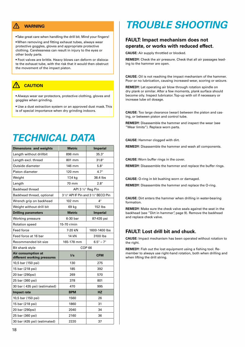
TECHNICAL DATADimensions and weights Metric Imperial
Length without drillbit 896 mm 35.3"
Length excl. thread 801 mm 31.8"
Outside diameter 146 mm 5.8"
Piston diameter 120 mm 4.7"
Weight 17,4 kg 38.4 lbs
Length 70 mm 2.8"
Backhead thread API 3 ½" Reg Pin
Backhead thread, optional 3 ½" API IF Pin and 3 ½" BECO Pin
Wrench grip on backhead 102 mm 4"
Weight without drill bit 69 kg 152 lbs
Drilling parameters Metric Imperial
Working pressure 6-30 bar 87-435 psi
Rotation speed 15-70 r/min
Feed force 7-20 kN 1600-1400 lbs
Feed force at 16 bar 14 kN 3100 lbs
Recommended bit size 165-178 mm 6.5" – 7"
Bit shank style COP 66
Air consumption at different working pressures
l/s CFM
10,5 bar (150 psi) 130 275
15 bar (218 psi) 185 392
20 bar (290psi) 269 570
25 bar (360 psi) 378 801
30 bar ( 435 psi) (estimated) 470 995
Impact rate BPM HZ
10,5 bar (150 psi) 1560 26
15 bar (218 psi) 1860 31
20 bar (290psi) 2040 34
25 bar (360 psi) 2160 36
30 bar (435 psi) (estimated) 2220 37
TROUBLE SHOOTINGFAULT: Impact mechanism does not operate, or works with reduced effect�CAUSE: Air supply throttled or blocked.
REMEDY: Check the air pressure. Check that all air passages lead-ing to the hammer are open.
CAUSE: Oil is not reaching the impact mechanism of the hammer. Poor or no lubrication, causing increased wear, scoring or seizure.
REMEDY: Let operating air blow through rotation spindle on dry plank or similar. After a few moments, plank surface should become oily. Inspect lubricator. Top-up with oil if necessary or increase lube oil dosage.
CAUSE: Too large clearance (wear) between the piston and cas-ing, or between piston and control tube.
REMEDY: Disassemble the hammer and inspect the wear (see ”Wear limits”). Replace worn parts.
CAUSE: Hammer clogged with dirt.
REMEDY: Disassemble the hammer and wash all components.
CAUSE: Worn buffer rings in the cover.
REMEDY: Disassemble the hammer and replace the buffer rings.
CAUSE: O-ring in bit bushing worn or damaged.
REMEDY: Disassemble the hammer and replace the O-ring.
CAUSE: Dirt enters the hammer when drilling in water-bearing formation.
REMEDY: Make sure the check valve seals against the seat in the backhead (see ”Dirt in hammer”, page 9). Remove the backhead and replace check valve.
FAULT: Lost drill bit and chuck�CAUSE: Impact mechanism has been operated without rotation to the right.
REMEDY: Fish out the lost equipment using a fishing tool. Re-member to always use right-hand rotation, both when drilling and when lifting the drill string.
19
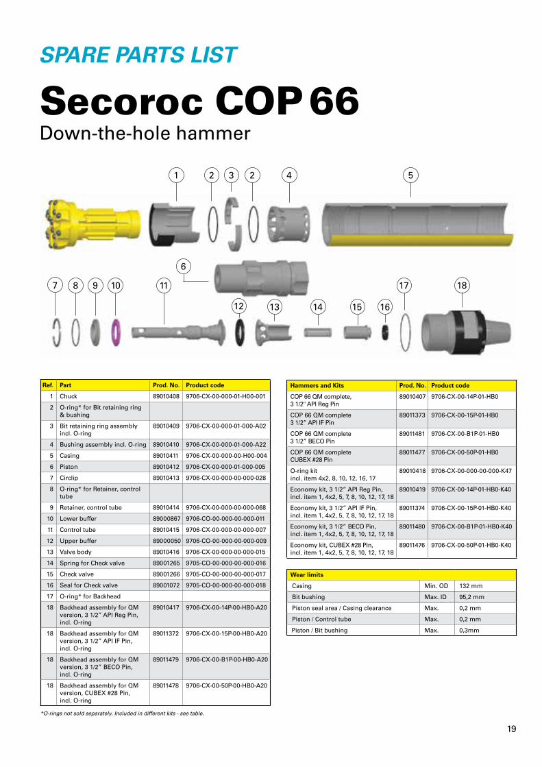
SPARE PARTS LIST
Atlas Copco Secoroc ABBox 521, SE-737 25 Fagersta, SwedenPhone +46 223 461 00 E-mail: [email protected]
Secoroc COP 66Down-the-hole hammer
Hammers and Kits Prod. No. Product code
COP 66 QM complete, 3 1/2" API Reg Pin
89010407 9706-CX-00-14P-01-HB0
COP 66 QM complete 3 1/2” API IF Pin
89011373 9706-CX-00-15P-01-HB0
COP 66 QM complete 3 1/2” BECO Pin
89011481 9706-CX-00-B1P-01-HB0
COP 66 QM completeCUBEX #28 Pin
89011477 9706-CX-00-50P-01-HB0
O-ring kit incl. item 4x2, 8, 10, 12, 16, 17
89010418 9706-CX-00-000-00-000-K47
Economy kit, 3 1/2” API Reg Pin, incl. item 1, 4x2, 5, 7, 8, 10, 12, 17, 18
89010419 9706-CX-00-14P-01-HB0-K40
Economy kit, 3 1/2” API IF Pin,incl. item 1, 4x2, 5, 7, 8, 10, 12, 17, 18
89011374 9706-CX-00-15P-01-HB0-K40
Economy kit, 3 1/2” BECO Pin,incl. item 1, 4x2, 5, 7, 8, 10, 12, 17, 18
89011480 9706-CX-00-B1P-01-HB0-K40
Economy kit, CUBEX #28 Pin,incl. item 1, 4x2, 5, 7, 8, 10, 12, 17, 18
89011476 9706-CX-00-50P-01-HB0-K40
Ref. Part Prod. No. Product code
1 Chuck 89010408 9706-CX-00-000-01-H00-001
2 O-ring* for Bit retaining ring & bushing
3 Bit retaining ring assembly incl. O-ring
89010409 9706-CX-00-000-01-000-A02
4 Bushing assembly incl. O-ring 89010410 9706-CX-00-000-01-000-A22
5 Casing 89010411 9706-CX-00-000-00-H00-004
6 Piston 89010412 9706-CX-00-000-01-000-005
7 Circlip 89010413 9706-CX-00-000-00-000-028
8 O-ring* for Retainer, control tube
9 Retainer, control tube 89010414 9706-CX-00-000-00-000-068
10 Lower buffer 89000867 9706-CO-00-000-00-000-011
11 Control tube 89010415 9706-CX-00-000-00-000-007
12 Upper buffer 89000050 9706-CO-00-000-00-000-009
13 Valve body 89010416 9706-CX-00-000-00-000-015
14 Spring for Check valve 89001265 9705-CO-00-000-00-000-016
15 Check valve 89001266 9705-CO-00-000-00-000-017
16 Seal for Check valve 89001072 9705-CO-00-000-00-000-018
17 O-ring* for Backhead
18 Backhead assembly for QM version, 3 1/2” API Reg Pin, incl. O-ring
89010417 9706-CX-00-14P-00-HB0-A20
18 Backhead assembly for QM version, 3 1/2” API IF Pin,incl. O-ring
89011372 9706-CX-00-15P-00-HB0-A20
18 Backhead assembly for QM version, 3 1/2” BECO Pin,incl. O-ring
89011479 9706-CX-00-B1P-00-HB0-A20
18 Backhead assembly for QM version, CUBEX #28 Pin,incl. O-ring
89011478 9706-CX-00-50P-00-HB0-A20
9853
124
2 01
a 20
14.1
0
21 3 4 5
7
16
17 18
15
8 9 10 11
12 13 14
2
Wear limits
Casing Min. OD 132 mm
Bit bushing Max. ID 95,2 mm
Piston seal area / Casing clearance Max. 0,2 mm
Piston / Control tube Max. 0,2 mm
Piston / Bit bushing Max. 0,3mm
*O-rings not sold separately. Included in different kits - see table.
6

9852
332
7 01
a S
ub
ject
to
alt
erat
ion
s w
ith
ou
t p
rio
r n
oti
ce f
rom
Atl
as C
op
co S
eco
roc
AB
. All
rig
hts
res
erve
d 2
016-
05
Atlas Copco Secoroc ABBox 521, 737 25 Fagersta, Sweden Phone: +46 223 461 00www.atlascopco.com/secoroc
We stand by our responsibilities towards our customers, towards the environment and the people around us. We make performance stand the test of time. This is what we call - Sustainable Productivity.