Embed Size (px)
Citation preview
Technical Specifications Section 15000 – Common Requirements For Mechanical Work
Project No. 08232-018 Fire Station Number 8
15000 - 1
SECTION 15000
COMMON REQUIREMENTS FOR MECHANICAL WORK
1.0 GENERAL
1.01 Scope of Division: Work shall include all materials, equipment, and labor necessary for a complete and properly functioning mechanical installation in accordance with requirements of the 2004 Florida Mechanical Code and to other pertinent codes made a part of such code by reference and local state codes, and contract drawings and specifications. Work shall be understood to include all work specified in Division 15, Mechanical, section numbers 15000 through 15999, inclusive, of the Specifications.
1.02 Drawings: Architectural and structural drawings take precedence over mechanical drawings with reference to the building construction. Mechanical drawings are diagrammatic and indicate the general arrangement and extent of work. Architectural drawings indicate more exactly the desired relationship between diffusers, registers, lighting fixtures, equipment, electric panels and devices, plumbing fixtures, and other items which remain exposed in the completed buildings. Exact locations and arrangements of materials and equipment shall be determined, with the approval of the Engineer, as work progresses to conform in the best possible manner with the surroundings and with the adjoining work of other trades. Where locations of equipment, devices or fixtures are controlled by architectural features, establish such locations by referring to dimensions on Architectural (A-series) drawings and not by scaling drawings.
1.03 Coordination of Work: Coordinate all work, prior to installation, with work of other trades and with architectural and structural features to preclude interference’s between the work of different trades and to insure necessary clearances at crossovers and equipment. Work requiring necessarily fixed locations (e.g., piping with required slopes, lighting fixtures, and diffusers in ceilings, etc.) takes precedence over work not requiring such fixed locations and shall establish permissible routing of services associated with the latter. Should work be performed without adequate coordination so that interference’s occur between work of different trades, the Contractor shall eliminate such interference’s by requiring necessary rework by the trades involved. Such rework shall meet express approval of the Architect and shall be performed at no addition to the contract amount.
1.04 Shop Drawings: Refer to "General Conditions". Submit to Architect for approval, before commencing work, shop drawings for all mechanical materials and equipment to be provided. In addition, submit other drawings or diagrams, dimensioned and in correct scale, requested by Architect to clarify the work intended or to show its relationship to adjacent work or work of other trades. Contractor is responsible for any delays in job progress accruing directly or indirectly from late submission of shop drawings. Shop drawings shall clearly show the following:
A. Technical and descriptive data in detail equal to or greater than the data given in the item specification. Indicate all characteristics, special modifications and features. Where performance and characteristic data is shown on the drawings or specified, submitted data shall be provided in a degree which is both quantitatively and qualitatively equal to that specified and shown so that
Technical Specifications Section 15000 – Common Requirements For Mechanical Work Project No. 08232-018 Fire Station Number 8
15000 - 2
comparison can be made. Present data in detail equal to or greater than that given in item specifications and include all weights, deflections, speeds, velocities, pressure drops, operating temperatures, operating curves, temperature ranges, sound ratings, dimensions, sizes, manufacturers' names, model numbers, types of material used, operating pressures, full load amperages, starting amperages, fouling factors, capacities, set-points, chemical compositions, certifications and endorsements, operating voltages, thicknesses, gauges and all other related information as applicable to particular item.
B. Exceptions to or deviations from the contract documents. Should Engineer approve any items having such deviations which are not clearly brought to Architect's attention, in writing, on item submittal, then Contractor is responsible for correction of such deviations regardless of when such deviations are discovered.
1.05 Record drawings:
A. Maintain one extra set of black-line, white print drawings for use as Record drawings. Records shall be kept daily, using colored pencil. As the work is completed, relevant information shall be transferred to a reproducible set, and copies made shall be given to the Architect.
B. As-built information shall be shown to scale, using standard symbols listed in the legend. As a minimum, show the following:
1. Location of stub-outs, dimensioned from permanent building lines.
2. Location and depth of under-slab and in-slab piping.
3. All routing of piping system.
4. Correct all equipment schedules.
5. Corrected numbers as they appear on the schedules.
6. Corrected motor horsepower electrical data.
1.06 Fees and Permit:
A. All work done under this Contract shall comply with all State and Local Codes having jurisdiction and with the requirements of the Utility Companies whose service may be used. All modifications required by these codes shall be made by this Contractor without additional charge. Where code requirements are less than those shown on the Plans or in the Specifications; the Plans and Specifications shall be followed. Where applicable, N.F.P.A. requirements shall be met.
B. The Contractor shall obtain all permits, inspections, and approvals as required by all authorities having jurisdiction. All fees and costs of any nature what-so-ever incidental to these permits, inspections, and approvals must be assumed and paid by this Contractor.
Technical Specifications Section 15000 – Common Requirements For Mechanical Work
Project No. 08232-018 Fire Station Number 8
15000 - 3
C. The Contractor shall comply with all applicable provisions of the Williams-Steiger Occupational Safety and Health Act.
2.0 PRODUCTS
2.01 General:
A. All materials and equipment shall be new and without blemish or defect.
B. Equipment and materials shall be products which will meet with the acceptance of the agency inspecting the work. Where acceptance is contingent upon having the products examined, tested, and certified by Underwriters or other recognized testing laboratory, the product shall be so examined, tested, and certified.
C. Substitutions: The following paragraphs shall govern should any conflict exist between these "substitution" paragraphs and any other paragraphs of Division 15.
1. Substituted equipment or optional equipment where permitted and approved, must conform to space requirements. Any substituted equipment that cannot meet space requirements, whether approved or not, shall be replaced at the Contractor's expense. Any modifications of related systems as a result of substitutions shall be made at the Contractor's expense.
2. Note that the approval of shop drawings, or other information submitted in accordance with the requirements herein before specified, does not assure that the Architect, or any other Owner's representative, attests to the dimensional accuracy or dimensional suitability of the material or equipment involved or the ability of the material or equipment involved or the mechanical performance of the equipment. Approval of shop drawings does not invalidate the plans and specifications if in conflict, unless a letter requesting such change is submitted by the Contractor and approved in writing by the Architect.
3. Substitutions of mechanical equipment for that shown on the schedules or designated by model number in the specifications will not be considered if the item is not a regular catalogued item shown in the current catalog of the manufacturer.
4. If bidder proposes to substitute materials and/or manufacturer's equipment in lieu of those specified, he shall submit written request to the Architect for approval no later than ten (10) days prior to the receipt of bids.
5. Requests submitted directly to the Owner or to the Architect's consultants and/or verbal requests will not be evaluated.
6. Should the proposed substitution be accepted, it will be incorporated into the Contract Documents by form of addendum.
Technical Specifications Section 15000 – Common Requirements For Mechanical Work Project No. 08232-018 Fire Station Number 8
15000 - 4
7. All substitutions proposed later than ten (10) days prior to the date for receipt of bids shall not be considered. Any substitution not accepted and any substitution request proposed later than ten (10) days prior to the date for receipt of bids shall not be used as either the basis for bidding or submittal after award of the contract.
D. Operating conditions and capacities must be as follows:
1. No overloading.
2. No operation at conditions outside of maximum and minimum limits recommended by the manufacturer and approved by the engineer.
3. Compatible with all systems.
E. Unless otherwise specified, all equipment and materials furnished must be as follows:
1. Recommended by the manufacturer for the application.
2. Installed in accord with the manufacturer's recommendations for the application except where specifications and drawings clearly indicate otherwise.
2.02 Sleeves:
A. General: Lay out work and set sleeves in new or existing construction so there shall be minimum of cutting, drilling and patching. All sleeves not used during construction period shall be sealed using grout. Unused penetrations or sleeves through fire rated barriers shall be sealed to prevent passage of smoke or heat using an Underwriters' Laboratories approved method rated at least equal to the barrier being penetrated. Method submitted must show proof of UL label.
B. Pipe sleeves:
1. Walls and partitions:
a. Sleeves 8 inch Diameter and Smaller (above grade): Sleeves shall be 18 gauge steel pipe or plastic sleeves built into wall, partition or beam, sized to pass pipe and covering, leaving a clear space of 1/4 inch minimum between covering and sleeve. Penetrations of fire rated barriers shall have 18 gauge steel sleeves.
b. Floors (above grade): Sleeves shall be Schedule 40 galvanized pipe or plastic, set before floor is poured, sized to pass pipe and covering, leaving a clear space of 1/4 inch between covering and sleeve, and shall extend 1/2 inch above finished floor.
Technical Specifications Section 15000 – Common Requirements For Mechanical Work
Project No. 08232-018 Fire Station Number 8
15000 - 5
c. Duct Sleeves: Sleeves or openings sized to pass mechanical ducts and covering shall be of framed construction in roof, wall, or partitions.
d. Sealing of sleeves:
1. Sleeves Above Grade: Openings around pipes, duct, etc., passing through sleeves shall be made draft free and vermin-proof by packing solidly with mineral wool or fiberglass.
2 Sealing Material: Where applicable and recommended by manufacturer, other sealing materials may be acceptable as options to above specified methods. Submit for Engineer approval prior to procurement.
2.03 Floor, Wall, and Ceiling Plates or Escutcheons, in Exposed Areas: Provide escutcheons or fabricated plates or collars at each location where pipe or exposed duct passes through a finished surface. Escutcheons for flush sleeves shall be chromium plated brass and sleeves extending above floor shall be chrome plated brass. Collars or plates for ducts and large diameter insulated pipe shall be fabricated of 18 gauge galvanized copper bearing sheet steel, secured to structure and neatly fitted around duct or pipe.
2.04 Motors: Unless specifically specified otherwise in the section covering the driven equipment (or the equipment drives), motors shall comply with the following:
A. Three Phase: NEMA design B, three-phase, squirrel cage induction type designed for 1800 rpm synchronous speed for operation in 40 degree C ambient at 1.15 service factor at constant speed on the scheduled voltage. Motors shall be insulated with Class B insulation material and shall be cast iron, drip proof, horizontal foot mounted type with ball bearings. Two speed motors shall be provided as scheduled and shall be two winding type.
B. Single Phase: Squirrel cage induction type designed for 1800 rpm synchronous speed for operation in 40 degree C ambient at 1.15 service factor at constant speed on the scheduled voltage. Motors shall be insulated with Class B insulation materials and shall be two winding capacitor start type with steel enclosure, drip proof, horizontal foot mount and ball bearings.
C. Scheduled Horsepowers: The horsepowers scheduled or specified are those nominal sizes estimated to be required by the equipment when operating at specified duties and efficiencies. In the case of pumps, these horsepowers are non-overloading and may also include provisions for future planned impeller changes. If the actual horsepower for the equipment furnished differs from that specified or shown on the drawings, it shall be the Contractor's responsibility to insure that proper size feeders, breakers, starters, etc. are provided at no change in contract price.
2.05 Substitutions Involving Electrical Changes: If the Contractor proposes items which have different electrical and/or control characteristics (such as larger amperage requirements, etc.) than those specified and provided for and/or which otherwise change the electrical
Technical Specifications Section 15000 – Common Requirements For Mechanical Work Project No. 08232-018 Fire Station Number 8
15000 - 6
and/or control system(s), then (even if the Architect approves such items) the Contractor must correlate all sizes, voltages, amperages and wiring for applicable items so that applicable electrical and/or control changes can be made. Contractor is responsible for all related additional costs. Other coordination is as specified elsewhere.
2.06 Belt Drives: Equip each motor driven machine not directly connected with V-belt drive. Belts shall be of correct cross section to fit properly in sheave grooves and shall be carefully matched for each drive. Sheaves shall be cast iron or steel, bored to fit properly on shafts and secured with keys of proper size. The rating of each drive shall be as recommended by manufacturer for service but shall be at least 1.5 times nameplate rating of motor.
A. Fan Belt Drives: Fixed pitch sheaves shall be provided.
B. Speed Adjustments: Adjust fan speed by change(s) in sheave size as necessary to obtain proper design air flow with fan in its installed location. Fans may be first fitted with variable pitch drive until proper fixed pitch drive size, or alternate sizes of fixed pitch drives may be used until proper fan speed is obtained. Provide all drives necessary to obtain proper fan speed needed to deliver necessary air quantity.
2.07 Bearings: All bearings shall be rated for 200,000 hour operating life unless indicated.
2.08 Belt and Coupling Guards: Each belt drive shall be equipped with an OSHA approved guard. Guards shall be constructed of #12 U.S. Standard gauges 3/4 inch diamond mesh wire screen, or equivalent, welded to one inch steel angle frames, and shall enclose all belts and sheaves. Tops and bottoms of guards shall be of substantial sheet metal or not less than #18 U.S. Standard gauge. Braces or supports must not "bridge" sound and vibration isolators. Guards shall be designed with adequate provision for movement of motor required to permit oiling, use of speed counters, and other maintenance and testing operations with guard in place. All direct drive equipment shall have coupling guards in accordance with Florida Department of Business Regulation safety regulations and OSHA.
2.09 Painting and Marking:
A. Painting: Painting of equipment, pipe, and ducts (insulated or uninsulated is specified under the "Painting" Division of these specifications. Touch-up of shop coat shall be performed under Division furnishing equipment.
B. Marking: Refer to Section entitled "Identification of Mechanical Systems".
2.10 Access Doors: Provide as necessary for access to concealed valves, cleanouts, unions, dampers, coils, junction boxes, etc., where no other means of access is shown or specified. Doors shall be manufactured by the Milcor Division of Inland-Ryerson, or an acceptable equal, type as follows:
Door Location Door Type
Drywall Style "DW"
Technical Specifications Section 15000 – Common Requirements For Mechanical Work
Project No. 08232-018 Fire Station Number 8
15000 - 7
Masonry or tile Style "M-Stainless"
Acoustical tile Style "AT"
Plaster Style "K"
Fire-rated walls Style "Fire Rated"
Each door shall be equipped with two flush, screwdriver operated, cam latches and, other than Style "M", shall be finished to match adjacent surface. Door sizes shall be applicable to the access required for normal service. See sections entitled "Ductwork" for access doors related to duct systems.
2.11 Excavation & Backfill:
A. Each subcontractor shall do trench and pit excavating and backfilling inside and outside the building, as required by his work, including shoring and bracing, pumping and protection for safety of persons and property.
B. Backfill shall be compacted in layers not exceeding six (6) inches in depth. Completed backfill shall conform to surrounding ground and finish grade and with compaction requirements of Division Two of these Specifications:
1. Concrete encasement: Piping passing under footings, foundations and other locations as shown on Drawings shall be encases by eight (8) inches (minimum) concrete on all sides. Concrete shall conform to Division Three requirements.
2. Extend concrete encasement eight (8) inches around piping and twelve (12) inches each side of footings or foundations.
C. Remove non-usable excavated material from the site. Deposit any usable surplus material on site where directed by the Project Architect/Engineer. Do not remove usable material from site.
D. Provide and maintain bracing, shoring or sheathing as required to safely support sides of excavations. The Contractor doing the excavation and the Contractor using the excavation are responsible for safety in excavations.
E. This Contractor shall provide and operate pumping equipment to keep excavations free of water.
F. This Contractor is responsible for repairing and restoring paving streets, curbs, walks and other work in the area where excavations are made.
G. Provide additional excavation and backfill where required to resolve conflicts in buried lines.
H. Coordinate timing of excavations in advance with other trades.
I. Excavation shall be open cut from the surface.
Technical Specifications Section 15000 – Common Requirements For Mechanical Work Project No. 08232-018 Fire Station Number 8
15000 - 8
J. Hold trench width to a minimum.
K. Do not excavate utility trenches parallel to building footings closer than four (4) feet from the footings except by approval of the Project Architect/Engineer. When parallel trenches require cuts deeper than the building footings, the horizontal distance from the footing shall be equal to, or greater than one and one-half (1-1/2) times the vertical distance below the footing, but in no case shall the horizontal distance be less than four (4) feet except by the approval of the Project Architect/Engineer.
L. Mechanical excavation shall be held to four (4) inches above final grade of the bottom of trench. The remainder shall be shaped by manual excavation, so that piping is fully supported on undisturbed soil. Shoring of piping in trench will not be allowed. Piping must be suspended from above.
M. Bell joint holes shall be carefully excavated so that none of the load is supported by the bells or joints.
N. Whenever, in the opinion of the Project Architect/Engineer, the soil is unsuitable for supporting piping and appurtenances, provisions for proper foundations shall be made at no additional cost to the Owner. Soil test reports are bound in the Specifications Book.
O. The drawings for this project show the anticipated underground utilities. Locations of utilities which will interfere with proposed construction shall be assumed to be a known factor to each subcontractor unless such locations on drawings are in error.
P. Wherever trenching or excavating, assume utilities may exist in area without such being shown on the drawings. Exercise extreme caution. Should existing facilities be damaged, repair such to Project Architect/Engineer's satisfaction at no additional cost to the Owner.
Q. Special care shall be taken with excavation in limited distance from existing trees. Manual excavation shall be required.
3.0 EXECUTION
3.01 Electrical and Control Work Coordination:
A. Definitions: Definitions for the purpose of mechanical/electrical control and power coordination are as follows. (Note: The use of the words, "Provide", "Furnish" and "Install" are intended only for use in describing the coordination indicated by this paragraph 3.01, and do not necessarily have the same definitions when used outside of the context of this paragraph 3.01). Any items which do not fall within the scope of this paragraph 3.01 shall be coordinated as individually specified.
1. "Furnish" means to procure an item and to deliver it to the project for installation.
Technical Specifications Section 15000 – Common Requirements For Mechanical Work
Project No. 08232-018 Fire Station Number 8
15000 - 9
2. "Install" means to determine (in coordination with others as necessary) the appropriate intended location of an item to set and connect it in place.
3. "Provide" means to both furnish and install.
4. Power Circuit: Circuit which carries main electric power to apparatus to which the power circuit is connected.
5. Control Circuit: Circuit which carries electrical signals directing the performance of a controller but which does not carry the main electric power. (See NEC, Section 430-71). Such circuits shall also include those which serve a dual control and power function (e.g., a line voltage thermostat circuit which both activates and powers a small fan motor).
6. Controller: A device, or group of devices, which serves to govern, in some predetermined manner, electric power delivered to apparatus to which the controller is connected and includes any switch or device normally used to start and stop a motor. (See NEC, Article 100, Definitions, "Controller", and Section 430-81(a).)
7. Control Device: A device which reacts to an operating condition (pressure, temperature, flow, humidity, etc.) and which initiates transmission of an electrical control signal which causes operation of a controller or which causes operation of pressure switches, etc.
B. Auxiliary Control Device: A device (such as a low voltage control transformer, electric relay, etc.) which is located in a control circuit and which carries or responds to (but does not initiate) an electrical control signal initiated by a control device.
C. Work of Division 15: includes (but is not necessarily limited to):
1. Provide:
a. All controllers which are generally manufactured or shipped as integral with Division 15 equipment (for example, such as starters packaged with packaged equipment, etc.).
b. All electric motors and other electrical power consuming equipment (such as electric air heating coils, electric hot water heaters, etc.) which are specified in Division 15.
c. All controls specified in Division 15 "HVAC Controls".
d. All control circuits (including conduit and boxes) from any Division 16 panels to power utilizing equipment provided by Division 15 and including the necessary circuit breakers.
e. All control connections to equipment provided by Division 15.
f. All control circuits, including conduit and boxes.
Technical Specifications Section 15000 – Common Requirements For Mechanical Work Project No. 08232-018 Fire Station Number 8
15000 - 10
g. All control connections to controllers, switches, motors and other mechanical systems electrical power consuming equipment (such as electric air heating coils, electric hot water heaters, etc.).
h. Auxiliary control devices.
i. All control devices (thermostats, pressure switches, flow switches, humidistats, etc.) and make control circuit connections thereto.
j. Any and all electronic and electric control devices and electric or pneumatic connections thereto.
k. Provide all starters for all mechanical equipment.
l. Provide all disconnects for all mechanical equipment.
2. Furnish: All controllers. Controllers shall comply with the requirements of applicable sections of Division 16.
D. Work of Division 16 includes (but is not necessarily limited to):
1. Provide:
a. All power circuits, including conduit and boxes.
b. All power connections to controllers, switches, motors and other mechanical systems, electrical power consuming equipment (such as electric air heating coils, electric hot water heaters, etc.).
c. All remote motor disconnects (remote from the related controller) at all locations required by NEC and connections thereto except those disconnects which are specified in Division 15 to be provided as part of the equipment itself.
2. Install: All controllers furnished by Division 15.
E. Other Requirements:
1. Interface Coordination: Contractor which supplies the power consuming equipment shall coordinate with actual contract document control and sequencing requirements regarding interface of the equipment with the control system specified in Division 15 and shall provide equipment wiring diagrams for final coordination for actual installation.
3.02 Tests:
A. General: All systems shall be inspected, tested, given a trial run, and demonstrated to Architect's and Owner's satisfaction that they are complete and ready for operation.
Technical Specifications Section 15000 – Common Requirements For Mechanical Work
Project No. 08232-018 Fire Station Number 8
15000 - 11
B. Plumbing Soil, Waste and Vent Piping: Test in accord with standard plumbing code and as otherwise specified.
C. All Other Piping: Unless required otherwise by code or other divisions of specifications, piping shall be tested at one hundred fifty percent (150%) of normal operating pressure for a continuous 24-hour period without leaking.
D. Systems - Air Conditioning: Refer to section describing test and balance of system.
E. Observation of Tests: Contractor shall notify Architect in writing at least two weeks prior to scheduled test(s) and demonstration(s) to allow Architect time to schedule his observation of Contractor's test(s) and demonstration(s).
3.03 Instruction: Refer to "Instruction and Maintenance Manuals" Section.
3.04 Acceptance:
A. Prior to requesting final inspection:
Complete all work required by drawings and specifications.
Acceptance will be made by the Architect on the basis of tests and inspection of project. Contractor shall furnish necessary mechanics to operate system, furnish test instruments and equipment as required, make necessary adjustments and assist with final inspection.
3.05 Protection of Work Until Final Acceptance: Contractor shall protect all materials and equipment from damage, the entrance of dirt and construction debris from the time of installation until final acceptance. Any materials and equipment that has been damaged shall be repaired to "as new" condition or replaced at the direction of the Architect. Where factory finishes occur and damage is minor, finishes may be touched-up. If, in the opinion of the Architect, the damage is excessive, factory finish shall be replaced to "new" condition.
END OF SECTION 15000
Technical Specifications Section 15005 – Instructions and Maintenance Manuals
Project No. 08232-018 Fire Station Number 8
15005 - 1
SECTION 15005
INSTRUCTIONS AND MAINTENANCE MANUALS
1.0 GENERAL:
1.01 Provide complete written and verbal operating and maintenance instruction to the Owner for all mechanical systems.
2.0 DOCUMENTATION:
2.01 Provide two (2) Instructions and Maintenance manuals, each complete as follows:
A. Hardback three ring loose-leaf binders.
B. Title sheet with job name, Contractor's subcontractors control subcontractor and related contractor's or material supplier’s names, addresses and phone numbers.
C. Index of contents.
D. A signed copy of acknowledgment of instructions to the Owner or his authorized representative. Two additional copies of the signed acknowledgment shall be sent directly to the Architect as soon as possible after receipt.
E. Typewritten operating instructions for the Owner's personnel describing the following for each piece of equipment and systems:
1. How to start and stop each piece of equipment.
2. How to set equipment and systems for normal operation.
3. Normal restarting procedures before contacting the service contractor.
4. Complete description of functions and operations of each piece of equipment including description of how equipment operates in conjunction with automatic control systems.
5. Instructions for cleaning, oiling, greasing, fueling and similar tasks.
F. Approved shop drawings and submittal data and parts and maintenance booklet for each item of material and equipment furnished under this Division, (but not limited to) the following:
1. Spare parts list and source of supply for each equipment item.
2. List of valves with location, service, size, model and operating position.
3. Diagrams clearly indicating automatic control hook-up.
G. Any as-built wiring diagrams as called for in other sections of this Division as needed to show how equipment controls interface with related systems.
Technical Specifications Section 15005 – Instructions and Maintenance Manuals Project No. 08232-018 Fire Station Number 8
15005 - 2
H. Contractor's Site Test and Balance report.
I. Copies of certificates of inspection.
J. Guarantees.
3.0 EXECUTION:
3.01 Verbal Instruction: Provide verbal, hands-on, operating and maintenance instruction to Owner's authorized personnel for each equipment item and system. Instruction shall be given by competent personnel.
END OF SECTION 15005
Technical Specifications Section 15020 – Piping and Fittings: Storm, Soil Waste, Vent and Drain
Project No. 08232-018 Fire Station Number 8
15020 - 1
SECTION 15020
PIPING AND FITTINGS: STORM, SOIL, WASTE, VENT AND DRAIN
1.0 GENERAL
1.01 Scope: Provide storm, soil, waste, vent and drain piping systems complete as indicated on drawings. Drawing scales prohibit the indication of all offsets, fittings, sleeves, and similar items; however, these deviations shall be provided as work of this section at no additional cost to Owner (no change in Contract price).
1.02 Shop Drawings: Refer to Section entitled "Common Requirements for Mechanical Work".
2.0 PRODUCTS
2.01 Pipe: Schedule 40 PVC.
2.02 Fittings: PVC solvent welded fittings.
3.0 EXECUTION
3.01 General: Refer to Section entitled "Common Requirements for Mechanical Work", paragraph entitled "Drawings".
3.02 Joints and Connections:
A. General: Joints and connections shall be made permanently air, gas, and water tight.
B. Connections: Provide fixture and equipment connections in compliance with requirements of local codes.
3.03 Flashings:
A. Floor Drains, Roof Drains, Showers, Etc.: Provide proper flashings for plumbing specialties installed in floors and roofs. Flashings shall be as per detail shown on architectural drawings.
B. Roof Penetrations: Provide flashing for all pipe passing through the roof. Minimum height of vents shall be one foot (1') above finished roof. Refer to architectural drawings for detail.
3.04 Cleanouts: Provide as indicated and as required by local code. Provide access covers as specified for concealed locations.
END OF SECTION 15020
Technical Specifications Section 15030 – Piping: Condensate Drain
Project No. 08232-018 Fire Station Number 8
15030 - 1
SECTION 15030
PIPING: CONDENSATE DRAIN
1.0 GENERAL
1.01 Scope: Provide condensate drain piping from cooling coil drain pans.
2.0 PRODUCTS
2.01 Pipe: Type M, DWV copper conforming to ASTM Spec. B88.
2.02 Fittings: Wrought copper, solder joint, pressure type conforming to ANSI B16.22.
2.03 Solder: Composition Sb5 (95/5).
3.0 EXECUTION
3.01 General: Piping shall be sloped uniformly toward drain, and provided with trap seal having a depth, in inches, equivalent to the total static pressure of the respective fan system. Traps shall be assembled using elbows and tees with threaded brass plugs to permit cleaning of trap and drain line. Piping shall be installed in a neat and workmanlike manner and shall not be smaller than full size of the equipment drain connection or three-quarters inch (3/4"), whichever is larger.
3.02 Routing: Route pipe discharge to nearest drain or as otherwise indicated on drawings.
3.03 Insulation: Insulate as specified in Section 15400 entitled "Thermal Insulation".
END OF SECTION 15030
Technical Specifications Section 15190 –Hangers and Supports: Piping Systems
Project No. 08232-018 Fire Station Number 8
15190 - 1
SECTION 15190
HANGERS AND SUPPORTS: PIPING SYSTEMS
1.0 GENERAL
1.01 Scope: Provide all angles, brackets, clamps, anchors, inserts, rods, braces, frames, hangers, nuts and bolts, and other miscellaneous steel and hardware items as may be required for the proper support of equipment and all piping systems.
1.02 Relation to Other Work: Contractor shall coordinate: shop drawings; placement; structural framing and overall building construction; and the work of all trades to insure an orderly and timely progress of the work. Refer to other Sections for special requirements relating to specific equipment and systems.
1.03 Manufacturer: Hangers and supports shall be as manufactured by Grinnell, Division ITT, F&S Manufacturing Corp.; Fee and Mason Manufacturing Co., or an approved equal.
2.0 PRODUCTS
2.01 Use the following (or approved equals thereof) if and as applicable to this project:
A. Hangers:
1. Hangers in contact with copper piping: Shall be copper plated or Teflon coated. Grinnell Fig. 97 or 97C.
2. Hangers (other than in contact with copper piping): Shall have manufacturer's standard finish. Pipe 3" and larger: Grinnell Fig. 260. Pipe 2-1/2" and smaller: Grinnell Fig. 104.
B. Pipe Roller Stands: Grinnell Fig. 274.
C. Pipe Roller Hangers: Grinnell Fig. 171.
D. Pipe Alignment Guide: Grinnell Fig. 256.
E. Pipe Riser Clamps: Grinnell Fig. 261.
F. Insulation Shields: Grinnell Fig. 292 with links.
G. Beam Clamps: Grinnell Fig. 292 with links.
H. Rod: Sized with safety factor of five (5). Grinnell Fig. 140 or 146.
3.0 EXECUTION
3.01 General: Refer to Section entitled "Common Requirements for Mechanical Work." All inserts, fasteners, hangers and supports shall be installed in strict accordance with manufacturer's instructions.
Technical Specifications Section 15190 –Hangers and Supports: Piping Systems Project No. 08232-018 Fire Station Number 8
15190 - 2
3.02 Pipe: Hangers shall be spaced to prevent sag and to permit proper drainage. All piping shall be run parallel with the lines of building, unless otherwise indicated on drawings. The hanger spacing and placement shall be such that after the covering (insulation and finish) is applied there will be not less than 1/2" clear space between finished covering and other surfaces, including the finished covering of parallel adjacent pipes. Hangers for insulated pipes shall be sized to encompass the insulating, finish and metal insulation shield (a metal insulation shield shall be provided for each hanger and support). Vertical piping shall be supported with pipe riser clamps at every floor penetration, unless specifically indicated otherwise on the drawings.
END OF SECTION 15190
Technical Specifications Section 15200 - Plumbing
Project No. 08232-018 Fire Station Number 8
15200 - 1
SECTION 15200
PLUMBING
1.0 GENERAL
1.01 Refer to Section 15000 entitled "Common Requirements for Mechanical Work".
1.02 Description of Work:
A. The extent of plumbing is indicated on the drawings and specifications.
B. In general, the work consists of, but is not limited to the following:
1. Hot and cold water supply piping, and all necessary valves, fittings, etc.
2. A system of soil, storm, waste and vent piping.
3. Natural gas piping and all necessary valves, fittings, etc.
4. Plumbing fixtures and trim.
5. Furnishing lead flashings for penetrations through the roof or as specified on drawings.
6. Connections of equipment furnished by others.
2.0 PRODUCTS
2.01 Refer to individual technical sections.
3.0 EXECUTION
3.01 The plumbing materials, fixtures and installation shall comply with all requirements of the latest edition of the 2004 Florida Building Code and all applicable state and local codes.
END OF SECTION 15200
Technical Specifications Section 15201 – Plumbing Fixtures, Trim, and Specialties
Project No. 08232-018 Fire Station Number 8
15201 - 1
SECTION 15201
PLUMBING FIXTURES, TRIM, AND SPECIALTIES
1.0 GENERAL
1.01 Refer to Section entitled "Common Requirements for Mechanical Work".
1.02 Energy Conservation Requirements:
A. Showers: Shower heads used shall be equipped with flow control devices to limit total flow to a maximum of two and a half (2.5) gallons per minute for ADA showers and a maximum of one and three quarts (1.75) gallons per minute for non-ADA showers.
B. Lavatories: Lavatories which are provided in public areas shall have the following feature: Outlet devices which limit the flow of water to a maximum of 0.5 GPM.
2.0 PRODUCTS
2.01 Plumbing Fixtures and Trim:
A. Provide all brackets, plates, anchors and fastening devices necessary for rigidly mounting fixtures in place. Unless noted otherwise, each wall hung plumbing fixture shall be supported on appropriate type of chair carriers.
B. Use chrome-plated brass piping where exposed to view between fixture and finished wall face and jacketed where fixture is designated for handicapped use. Provide tight fitting escutcheons of chrome plated brass wherever piping passes through walls. Supply piping to all fixtures shall be anchored to prevent movement.
C. Approved Manufacturers:
1. Fixtures: American Standard, Crane, Eljer, Elkay, Just, Fiat or Kohler.
2. Flush Valves: Delaney, Sloan or Zurn.
3. Toilet Seats: Bemis, Beneke, Church, Olsonite or Centoco.
4. Trim: American Standard, Chicago, Crane, Eljer, Kohler, T&S Brass, Zurn or Symmons.
5. Electric Water Coolers: Elkay, Halsey Taylor or Oasis.
D. General:
1. Acid resisting enamel for enameled cast iron and steel fixtures.
Technical Specifications Section 15201 – Plumbing Fixtures, Trim, and Specialties Project No. 08232-018 Fire Station Number 8
15201 - 2
2. Cast brass P-trap with cleanout for each lavatory and sink unless otherwise indicated.
3. Renewable seats and disks for supply valves.
4. Stops for fixture hot and cold water supplies.
2.02 Plumbing Specialties:
A. Cleanouts:
1. Exterior type: Heavy-duty cast iron body with round, scoriated, non-tilt top.
2. Interior floor type: Cast iron with square, heavy duty, scoriated nickel bronze top.
3. Interior wall type: Cast iron cleanout tee with countersunk plug and square, smooth nickel bronze access cover and frame.
4. Plugs: Heavy cast iron ferrule with screw plug.
5. Josam, J. R. Smith, Wade, Zurn, Sioux Chief or approved equal. Refer to schedule on drawings.
B. Traps:
1. Deep seal type on all floor drains.
2. Exposed and/or in cabinets: Chrome plated cast brass with cleanouts.
C. Water Hammer Arresters:
1. Shall be in accord with Plumbing and Drainage Institute Standard PDI-WH-201.
2. Josam, J. R. Smith, Wade, Zurn or Sioux Chief are approved equals.
D. Floor Drains:
1. Adjustable height, cast iron body, double drainage flanges, flashing clamp, nickel bronze strainer, no integral trap, inside caulk bottom outlet with adapter for ring.
2. 6" strainer.
3. Polished brass strainer in equipment rooms.
4. Automatic trap primer connection except on shower drains.
Technical Specifications Section 15201 – Plumbing Fixtures, Trim, and Specialties
Project No. 08232-018 Fire Station Number 8
15201 - 3
5. Josam, J. R. Smith, Wade, Zurn or Sioux Chief are approved equals. Refer to schedule on the drawings.
3.0 EXECUTION
3.01 General:
A. Protect chrome-plated items from damage by wrenches and other hazards.
B. Install fixtures having flush valves so that supplies to valves for all identical fixtures in each room are at same height for that fixture type. Seat valve in place so that valve discharge centerline is directly above fixture spud centerline; do not connect by bending nipple between valve spud.
C. Install cold water on right (facing applicable fixtures).
D. Verify, coordinate, adjust, align and secure rough-in piping to provide neat appearances and serviceable operation. Correlate with fixture manufacturer's data and recommendations and with required dimensions.
3.02 Cleanouts:
A. Install at or near foot of each soil or waste stack and at each change in direction of building drain greater than 45 degrees.
B. Shall be accessible; install flush with finished wall, floor or finished grade.
3.03 Traps:
A. Trap each fixture (except those with integral traps) with water sealed trap located as close as possible to fixture and never greater than 24" from fixture.
B. Provide all floor drains and hub drain traps and indirect waste traps with automatic primer system for each trap.
3.04 Water Hammer Arresters: Size and locate in accord with PDI Standard PDI-WH-201.
3.05 Final Installation: Final installation of all drains (floor, roof, hub, shower and other similar types) must yield absolutely permanently water tight floor and/or roof system.
END OF SECTION 15201
Technical Specifications Section 15210 – Domestic Water System
Project No. 08232-018 Fire Station Number 8
15210 - 1
SECTION 15210
DOMESTIC WATER SYSTEM
1.0 GENERAL
1.01 Scope: Provide potable water systems complete as indicated on the specifications and drawings. Drawings scales prohibit the indication of all offsets, fittings, sleeves, and similar items; however, these deviations shall be provided as work of this Section at no additional cost to the Owner. (No change in Contract price).
1.02 Shop Drawings: Refer to Section 15000 entitled “Common Requirements for Mechanical Work”.
2.0 PRODUCTS
2.01 Interior Water Pipe: Cold water supply piping below grade up to a point five feet outside the building line shall be type K hard drawn seamless copper water tube in a vinyl sleeve conforming to ASTM B88-89. Hot and cold water supply piping above grade shall be type L hard drawn seamless copper water tube conforming to ASTM B88.
2.02 Fittings: Wrought copper, pressure type conforming to ASTM B16.22-1989.
2.03 Solder: Lead free, 95-5 non-corrosive flux.
2.04 Pipe Protective Coating (Interior): Protect hot and cold water piping below floor or in contact with concrete by wrapping with 20 mil thickness vinyl tape equal to Permacel No. 307.
2.05 Dielectric Isolators:
A. Unions: For pipe sizes two inches (2”) and smaller, EPCO or Rockford-Eclipse insulated unions with joint connection to suit pipe and equipment.
B. Flanges: For pipe sizes two and one-half inches (2-1/2”) and over; Plico Products flange insulation sets with: phenolic retainer, nitrile rubber seal element, polyethylene sleeves and double washer sets. Spring lock type with set screw.
2.06 Relief Valves: ASME rated; size and setting as recommended by equipment manufacturer and/or indicated on drawings.
2.07 Valves:
A. All valves shall have the name or trademark of the manufacturer and the guaranteed working pressure cast or stamped on the body. Adapters shall be provided for all valves on copper lines.
Technical Specifications Section 15210 – Domestic Water System Project No. 08232-018 Fire Station Number 8
15210 - 2
B. All stop valves used on this work, unless otherwise specified or required, shall be of the gate pattern, suitable for 125 pound working pressure.
C. All gate valves shall be packed and left perfectly tight at the completion of work.
D. Gate Valves: Gate valves two inches (2”) and smaller shall be made of the best brass of screwed pattern of the solid wedge type, double seat, non-rising stem, with gland stuffing box and iron wheel, NIBCO T-133, Stockham B-128 or Jenkins 370C. Gate valves two and one-half inches (2-1/2”) or larger shall be iron body, brass trimmed, flanges ends and otherwise same type as smaller valves, NIBCO F617-0, Stockham 9-623 or Jenkins 651C.
E. Globe Valves: Globe valves 2: and smaller shall be the best grade brass, screwed pattern, removable disc suitable for the fluid to be controlled with gland stuffing box and iron wheel, NIBCO T235-Y, Jenkins 106B or Stockham B-22-T. Globe valves two and one-half inches (2-1/2”) and larger shall be iron body, brass trimmed, flanged ends and otherwise same type as smaller valves. NIBCO F178-B, Jenkins 613C or Stockham 9-512.
F. Check Valves: check valves two inches (2”) and smaller shall be made of the best grade brass, screwed pattern, swing check, one disc for hot and cold water; NIBCO T4-413-BY, Jenkins 996 or Stockham B-319. Check valves two and one-half inches (2-1/2”) and larger shall be iron body.
G. Ball valves two inches (2”) and smaller shall be all bronze of compact pattern with solder joint connections rated at 400 pounds WOG. Stem extensions shall be furnished for use in insulated lines where insulation exceeds 1/2” Ball valves may be substituted for gate valves in sizes two inches (2”) and smaller. NIBCO S-580, Milwaukee BA 100/150 Apollo 70-100/200.
3.0 EXECUTION
3.01 Joints and Connections:
A. General: Joints and connections shall be made permanently air, gas and watertight.
B. Equipment Connections: Final connections to services and connections to equipment shall be made with unions for pipe sizes two inches (2”) and under and with companion flanges for pipe two and one-half inches (2-1/2”) and larger. Where incompatible piping material comes in contact, except for the use of valves, isolate the two materials using dielectric isolators as specified herein before.
C. Piping drops to points of use shall each be valved for individual shut-offs.
3.02 Valves: All valves, stops, pressure regulators and similar items shall be installed in an easily accessible location. Provide access panel (refer to Section 15000 entitled “Common Requirements for Mechanical Work”) for all concealed valves.
Technical Specifications Section 15210 – Domestic Water System
Project No. 08232-018 Fire Station Number 8
15210 - 3
3.03 Sterilization: Sterilization solution shall be 400 PPM to 1000 PPM chlorine made from a sanitation grade chlorine or sodium hypochlorite. Solution shall remain in system for twenty four (24) hours during which time valves and faucets are to be opened and closed several times. Outlets shall be tested to insure an adequate amount of chlorine is present. At conclusion of sterilization entire system shall be flushed with clean water until chlorine content is at a level approved by the County Health Department.
3.04 Tests: Upon completion of the water supply system it shall be tested and proved tight under a water pressure no less than 25 PSI above the working pressure under which it is to be operated and retained for not less than 24 hours .s shall be observed by a representative of the Project Architect/Engineer before it is removed.
END OF SECTION 15210
Technical Specifications Section 15211 – Grease Interceptor
Project No. 08232-018 Fire Station Number 8
15211 - 1
SECTION 15211
GREASE INTERCEPTOR
1.0 GENERAL
1.01 Scope: Provide underground reinforced concrete grease interceptor in accordance with all applicable requirements of Plumbing and Drainage Institute Standard PDI-G101, EPA Manual, Florida Administrative Code 10D-6 and local plumbing codes.
1.02 Relation to Other Work: Refer to Section 15000 entitled "Common Requirements for Mechanical Work".
1.03 Shop Drawings: Refer to Section 15000 entitled "Common Requirements for Mechanical Work". Include complete data on: dimensions; working pressure; code compliance; protective finish; acceptance by local authority; manhole; and all accessories.
1.04 Operating and Maintenance Instructions: Refer to Section 15000 entitled "Instruction and Maintenance Manuals".
1.05 Industry Standards: Where compliance with an industry, society, or association standard is specified or indicated, certification of such compliance shall be submitted with shop drawings.
2.0 PRODUCTS
2.01 Interceptor: Shall be of capacity as indicated on Drawings, precast or poured in place reinforced concrete with manhole access to inlet and discharge fittings. Inlet fitting shall be four inch PVC short pattern combination with twelve inch long tailpiece. Outlet fitting shall be four inch PVC short pattern combination with tailpiece extended to twelve inches above floor of interceptor. Precast grease traps shall be as manufactured by Robinson Concrete Specialties, Incorporated or approved equal.
3.0 EXECUTION
3.01 Interceptor shall be installed plumb and level in all respects, on stable compacted earth. If earth is determined to be unstable, lime rock or concrete base shall be provided to obtain adequate stability.
END OF SECTION 15211
Technical Specifications Section 15215 – Storm Water System
Project No. 08232-018 Fire Station Number 8
15215 - 1
SECTION 15215
STORM WATER SYSTEM
1.0 GENERAL
1.01 Scope: Provide storm water piping system complete as indicated on drawings. Drawing scales prohibit the indication of all offsets, fittings, sleeves, and similar items; however, these deviations shall be provided as work of this section at no additional cost to Owner (no change in Contract price).
1.02 Shop Drawings: Refer to Section 15000 entitled "Common Requirements for Mechanical Work".
2.0 PRODUCTS
2.01 Pipe and Fittings:
A. Interior above first floor slab shall be schedule 40 polyvinylchloride pipe with PVC solvent welded fittings.
B. Interior below floor slab and up to a point five feet (5'-0") beyond the building walls shall be type PVC DWV pipe and fittings (ASTM 2665-88).
2.02 Roof Drains: All roof drains will be furnished and installed with sheet lead flashing of dimensions and configurations as shown on A-series drawing. Provide all accessories required for the particular construction in which they are to be mounted. Josam, J. R. Smith, Wade or Zurn are approved manufacturers. Refer to schedule on drawings.
3.0 EXECUTION
3.01 General: All piping shall be run in the most direct manner. Horizontal pipes shall have a grade of one-quarter inch (1/4") per foot wherever possible, and not less in any case than one-eighth inch (1/8") per foot. All offsets shall be 45 degrees or less.
3.02 Insulation: Refer to Section 15400 entitled "Thermal Insulation".
3.03 Tests: All storm drains shall be tested by filling leader with water to 10 feet head minimum and allowing to stand twenty-four (24) hours with no loss of head. Any tests shall be observed by a representative of the Architect before tests are removed.
END OF SECTION 15215
Technical Specifications Section 15220 – Sanitary Drainage System
Project No. 08232-018 Fire Station Number 8
15220 - 1
SECTION 15220
SANITARY DRAINAGE SYSTEM
1.0 GENERAL
1.01 Scope: Provide soil, waste and vent piping systems complete as indicated on specifications and drawings. Drawing scales prohibit the indication of all offsets, fittings, sleeves and similar items; however, these deviations shall be provided as work of this section at no additional cost to Owner (no change in Contract price).
2.0 PRODUCTS
2.01 Pipe and Fittings:
A. Interior above first floor slab shall be schedule 40 polyvinylchloride pipe with PVC solvent welded fittings.
B. Interior below floor slab and up to a point five feet (5'-0") beyond the building walls shall be type PVC DWV pipe and fittings (ASTM 2665-88).
2.02 Floor Drains: Floor drains shall be as manufactured by Josam, J.R. Smith, Wade or Zurn. Provide flashing clamp devices where required by floor construction. Refer to schedule on drawings.
3.0 EXECUTION
3.01 General: Contractor shall promptly install all sewer and drain piping after excavating, chasing, or cutting for same has been done, so as to keep the openings for such piping open as short a time as possible. No piping shall, however, be permanently closed up, furred in or covered before the examination of it by the authorities having jurisdiction.
3.02 Scope: All piping shall be run in the most direct manner. Horizontal pipe shall have a grade of one-quarter inch (1/4") per foot wherever possible and not less, in any case, than one-eighth inch (1/8") per foot. All offsets shall be 45 degrees or less.
3.03 Insulation: Refer to Section 15400 entitled "Thermal Insulation".
3.04 Cleanouts: Refer to Section 15201 entitled "Plumbing Fixtures Trim and Specialties".
3.05 Vents: Vent branches shall be kept above the fixtures in such a manner as to preclude the use of the vents as waste pipes should the latter become obstructed. All branches shall be so graded as to prevent accumulation of water or scale therein. All vent pipes shall be properly graded without drops or sags and so connected as to drip back to waste pipes by gravity. Wherever practicable, two or more vents shall be connected together and extended as one vent through the roof.
Technical Specifications Section 15220 – Sanitary Drainage System Project No. 08232-018 Fire Station Number 8
15220 - 2
3.06 Escutcheons: Where waste and vents are exposed at fixtures, pipes shall be chrome-plated brass (iron pipe size) and have chrome-plated escutcheons where they pass through floors, walls, or ceilings.
3.07 Flashing: At all points where the vents pass through the roof, the openings shall be flashed with sheet lead flashing weighing not less than four (4) pounds per square foot. The flashing shall be made absolutely watertight at the roofline and shall be extended up, over and down at least two inches (2") into the pipe. Each flange shield shall extend not less than fourteen inches (14") in all directions from the respective vent, underneath the roofing material.
3.08 Tests: After all soil, waste and vent stacks have been installed, the outlets shall be plugged and the piping system filled with water to the highest point of the system, but with no less than 10 ft head of water, and allowed to remain filled for twenty-four (24) hours and proved tight under such conditions. This test may be conducted in segments as required by the sequence of construction. All tests shall be observed by a representative of the Project Architect/Engineer before tests are removed.
END OF SECTION 15220
Technical Specifications Section 15224 – Natural Gas Piping System
Project No. 08232-018 Fire Station Number 8
15224 - 1
SECTION 15224
NATURAL GAS PIPING SYSTEM
1.0 GENERAL
1.0 Scope:
A. Work under this section of the specifications shall include furnishing, installing and testing the complete natural gas pipeline systems including piping, fittings, valves, outlets, cylinder manifolds, alarms, etc. (Electrical wiring shall be part of the electrical work under Division 16).
B. All systems shall be complete in every aspect and ready to be put into operation. All materials used shall be new and of the best grade and quality obtainable, and workmanship shall be first class in every respect. The subcontractor shall be responsible for compliance with all local, state or federal codes and local gas company regulations applicable to this installation.
C. The contractor shall arrange with the local gas utility for, and shall pay all charges incidental to, extending an underground service line and the installation of the gas meter. The contractor shall connect to the house side of the meter a complete natural gas piping system as shown on the drawings.
1.02 Specifications and Drawings:
A. The plans show the location of all fixtures and equipment and are intended to depict the general intent of the work, in scope, layout and quality of workmanship. They are not intended to show, in minute detail, each and all accessories intended for the purpose of execution of the work, but shall be understood that such details will be part of this work.
B. Where drawings and specifications conflict, it shall be the responsibility of this contractor to bring such conflict to the attention of the Architect for clarification.
1.03 Relationship to Other Work: Refer to Section 15000 entitled "Common Requirements for Mechanical Work". Piping systems requiring fixed locations and slopes shall take priority over those which do not have these requirements.
1.04 Shop Drawings: Refer to Section 15000 entitled "Common Requirements for Mechanical Work".
1.05 Quality Assurance:
A. Manufacturers: Firms regularly engaged in manufacture of natural gas piping products, of types, materials, and sizes required, whose products have been in satisfactory use in similar service for not less than 5 (five) years.
Technical Specifications Section 15224 – Natural Gas Piping System Project No. 08232-018 Fire Station Number 8
15224 - 2
B. Installer: A firm with at least 3 (three) years of successful installation experience on projects with natural gas piping system work similar to that required for project.
C. ANSI Code Compliance: Comply with applicable provisions of ANSI B31.2 "Fuel Gas Piping".
D. National Fuel Gas Code Compliance: Comply with applicable provisions of NFPA 54 (ANSI Z223.1) "National Fuel Gas Code", and ANSI Z223.1a "Supplement to National Fuel Gas Code".
E. Local Utility Compliance: Comply with requirements of local gas utility company.
1.06 Industry Standards: Where compliance with an industry, society or association standard is specified or indicated, certification of such compliance shall be submitted with shop drawings. Equipment shall, where applicable, be the same manufacturer throughout the system and shall be Underwriters Laboratories listed or Factory Mutual approved.
2.0 PRODUCTS:
2.01 Pipe and Fittings: Natural gas piping shall be standard weight black steel pipe conforming to ASTM A-120-84 with black malleable iron fittings conforming to ASTM A197-87. All piping two and one-half inches (2-1/2") and larger shall be welded. Welding fittings shall be Tube-Turns Schedule 40. Steel tubing for gas lines shall comply with specification for electric resistance-welded coiled steel tubing conforming to ASTM A53-87b.
2.02 Gas Cocks:
A. Gas Cocks 2" and Smaller: 150 psi non-shock, WOG, bronze straightway cock, flat or square head, threaded ends, Jenkins No. 30A.
B. Gas Cocks 2 1/2" and Larger: 125 psi non-shock, WOG, iron body, bronze mounted, straightway cock, square head, flanged ends. Nordstrom No. 142 or 143.
2.03 Control Valves: Master Gas Control Valve: Bronze body, packless, single seat, explosion-proof, solenoid operated, normally closed, UL approved, automatic reset, 120 volt.
2.04 Pressure Regulating Valves: Provide single stage, steel jacketed, corrosion resistant gas pressure regulators; with atmospheric vent, elevation compensator; with threaded ends for 2" and smaller, flanged ends for 2-1/2" and larger; for inlet and outlet gas pressures, specific gravity, and volume flow indicated.
3.0 EXECUTION
3.01 Gas Service:
Technical Specifications Section 15224 – Natural Gas Piping System
Project No. 08232-018 Fire Station Number 8
15224 - 3
A. Arrange with utility company to provide gas service to indicated location with shutoff valve at terminus. Consult with utility as to extent of its work, costs, fees and permits involved. Pay such costs and fees; obtain permits.
B. Extend service pipe from utility's terminus to inside building wall, under utility's direction.
C. Provide shutoff in gas service pipe at entry to building, extend pipe to gas meter location indicated; provide parts and accessories required by utility to connect meter.
3.02 Installation of Piping:
A. All piping shall be run straight without sags or traps and shall be so pitched as to drain back to the riser and from the riser to the meter. A drip pocket consisting of a nipple and a cap shall be screwed into the bottom of each riser and at all low points of the gas distributing system. Install all piping in accordance with 2004 Florida Building Code and the local authorities having jurisdiction.
B. All gas piping within the building shall be run exposed unless specifically shown otherwise on the drawings.
C. All pipe and fittings in the ground shall be protected against corrosion by a wrapping applied in accordance with the standards of the gas company. Field-fabricated joints shall be similarly protected. Exposed piping between meter and building shall be cleaned and painted with one coat asphaltic aluminum paint.
D. For piping buried in building substrate, or below floor slabs, install in welded conduit, ventilated to outdoors on both ends, and tested to same requirements as gas piping.
E. Plug each gas outlet, including valves, with threaded plug or cap immediately after installation and retain until continuing piping, or equipment connections are completed.
3.03 Tests: The complete natural gas piping system shall be tested at 75 PSIG for three (3) hours with no pressure drop or as requested by the local administrative authority or the local gas company. Ether or peppermint fumes shall be used to locate leaks. All tests shall be observed by a representative of the Architect and local gas company before the tests are removed.
3.04 Purging: After the piping system has been checked and tested it shall be purged. Under no circumstances shall a line be purged into the combustion chamber of an appliance. The open ends of piping systems being purged shall not discharge into confined spaces or areas where there are sources of ignition unless precautions are taken to perform purging in a safe manner by ventilation of the space, control of purging rate and elimination of all hazardous conditions.
Technical Specifications Section 15224 – Natural Gas Piping System Project No. 08232-018 Fire Station Number 8
15224 - 4
3.05 Painting: Piping exposed in finished areas shall be painted in a color to be selected by the Architect. Under no circumstances shall painting be done before testing and approval of the system is complete.
END OF SECTION 15224
Technical Specifications Section 15305 – Fire Sprinkler Systems
Project No. 08232-018 Fire Station Number 8
15305 - 1
SECTION 15305
FIRE SPRINKLER SYSTEMS
1.0 GENERAL
1.01 Scope: Provide complete automatic wet pipe type sprinkler system for the areas and occupancies shown on the drawings. System shall be designed and installed in accordance with: A) 2002 Edition of NFPA 13 Standard for the "Installation of Sprinkler Systems", B) Building and Fire Codes of local and state authorities having jurisdiction, C) Underwriters Laboratories, and D) Factory Mutual Standards.
1.02 Shop Drawings:
A. Refer to Section entitled "Common Requirements for Mechanical Work". Calculation for hydraulic design shall be submitted with working plans and results of recent flow test (to determine the adequacy of the water supply before construction begins) showing approval by the "Authority Having Jurisdiction".
B. Within thirty (30) days after the award of contract and prior to fabrication, complete shop drawings of the sprinkler systems, including manufacturer's equipment data and catalog sheets, shall be submitted to the following.
1. Insurance association having jurisdiction.
2. Local authorities having jurisdiction.
C. When approved shop drawings are obtained from the above jurisdictions, they shall be immediately submitted to the architect for his review.
D. Drawings shall be based on the latest floor plans, which are available at that time.
1.03 Industry Standards: Where compliance with an industry, society or association standard is specified or indicated, certification of such compliance shall be submitted with shop drawings. Equipment shall, where applicable, be Underwriters Laboratories listed or Factory Mutual approved.
1.04 Design Parameters:
A. General: Pipe sizes shall be hydraulically calculated and designed in accordance with NFPA 13, based on the occupancy classification of the protected area as scheduled on the drawings or as otherwise defined. Where a system is scheduled to include more than one occupancy classification, the hydraulic calculations shall be based on the higher demand or duplicate
Technical Specifications Section 15305 – Fire Sprinkler Systems Project No. 08232-018 Fire Station Number 8
15305 - 2
calculations may be submitted to show that each demand is met in its particular area.
B. Light Hazard Occupancies: Shall be designed to provide a minimum density of 0.10 GPM per square foot for the most hydraulically remote 1500 square feet of system coverage and 100 GPM for inside and outside hose streams. Sprinkler spacing shall not exceed 225 square feet per sprinkler.
C. Ordinary Hazard Occupancies:
1. Group I: Shall be designed to provide a minimum density of 0.15 GPM per square foot for the most hydraulically remote 1500 square feet of system coverage and 250 GPM for inside and outside hose streams. Sprinkler spacing shall not exceed 130 square feet per sprinkler.
2. Group II: Shall be designed to provide a minimum density of 0.20 GPM per square foot for the most hydraulically remote 1,500 square feet of system coverage and 250 GPM for inside and outside hose streams. Sprinkler spacing shall not exceed 130 square feet per sprinkler.
1.05 Water Supply: Shall be connected to a reliable and adequate water supply as described in NFPA 13 and indicated on the drawings.
1.06 Type of Construction: Shall be as indicated on the drawings or as defined by NFPA 13.
2.0 PRODUCTS
2.01 Pipe, Valves and Specialties:
A. Piping and Valves:
1. Fire protection piping above grade, inside buildings, shall be as shown on drawings. Fittings generally shall be UL approved, Victaulic piping fittings and Victaulic Style 77 couplings on 3" and larger sizes. All fittings and couplings shall be screwed for pipe 2-1/2" or smaller. All Victaulic Style 77 couplings shall have housing fabricated in two or more parts malleable iron castings; coupling gasket shall be Victaulic Grade "H" molded synthetic rubber; coupling bolts shall be oval neck track head type. Victaulic fittings shall be fabricated of malleable iron casting in accordance with Federal Specification QQ-1-666c, Grade II.
2. Before assembly of couplings, lightly coat pipe ends and outside of gaskets with grease or graphite paste.
3. Pipe grooving shall be in accordance with the manufacturer's specifications contained in latest published literature.
Technical Specifications Section 15305 – Fire Sprinkler Systems
Project No. 08232-018 Fire Station Number 8
15305 - 3
4. Fire Protection System gate valves shall be UL/Fm approved, class 200, solid wedge disc, O.S. & Y. or butterfly type.
5. Fire Protection System check valves 2-1/2" and smaller shall be Crane No. 41, made of best grade brass and screwed pattern. Check valves 3" and larger shall be UL/FM approved, swing check, bolted cap, high strength cast iron body and cap, bronze trim, flanged, Crane No. 375 or Jenkins.
6. All valves where shown on the drawings shall be electrically supervised with tamper switch wired to alarm bell at central panel. Coordinate wiring with valve and controls.
7. Check valves for Siamese fittings shall be provided with Potter-Roemer, Inc., No. 5980 automatic ball drip, piped to drip over a floor drain.
8. System to be installed to UL Standards and to their approval.
9. Where piping passes through walls, floors, ceilings, or other building construction, sleeves (UL Classified assembly) must be used. Where exposed piping passes through finished work, escutcheons shall be chrome plated or other finishes acceptable to the Architect. Split wall plates or escutcheons shall be installed to fit snuggly around piping. Where finish is not a problem, suitable plates shall be provided at each hole to assure effectiveness of construction as a fire stop.
10. Piping in areas having ceilings shall be concealed. Piping in other areas may be exposed, but kept at a minimum distance from structural systems. All piping shall be free of rust, clean and have a minimum of one shop coat of rust inhibiting paint.
B. Wet Pipe Sprinkler System: Shall consist of riser check valve trimmed for vertical or horizontal installation with complete trim piping, valve and fittings including flow switch. Piping arrangements and system boundaries shall be as indicated on the construction drawings.
2.02 Hangers and Supports: Refer to the Section entitled "Hangers and Supports: Piping System".
2.03 Sprinkler Heads
A. General: Shall be types as shown on drawings. Sprinklers shall be designed for a 175-PSI w.w.p. All sprinklers shall be UL listed and/or FM approved. All heads located in any area subject to mechanical injury shall be protected with approved guards. A reserve supply of sprinklers, quantity in accordance with NFPA 13-2002, shall be provided in a metal cabinet with at least one sprinkler wrench for each type of sprinkler used. Cabinet shall, as a minimum, contain at least two of
Technical Specifications Section 15305 – Fire Sprinkler Systems Project No. 08232-018 Fire Station Number 8
15305 - 4
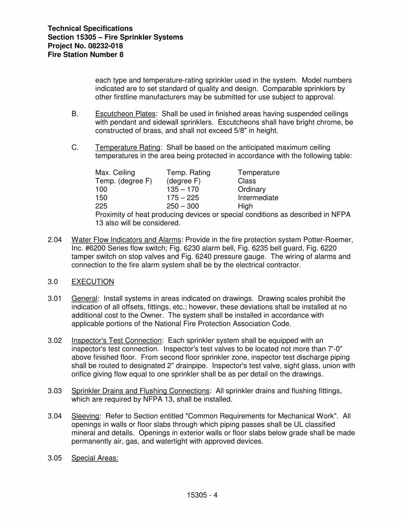
each type and temperature-rating sprinkler used in the system. Model numbers indicated are to set standard of quality and design. Comparable sprinklers by other firstline manufacturers may be submitted for use subject to approval.
B. Escutcheon Plates: Shall be used in finished areas having suspended ceilings with pendant and sidewall sprinklers. Escutcheons shall have bright chrome, be constructed of brass, and shall not exceed 5/8" in height.
C. Temperature Rating: Shall be based on the anticipated maximum ceiling temperatures in the area being protected in accordance with the following table:
Max. Ceiling Temp. Rating Temperature Temp. (degree F) (degree F) Class 100 135 – 170 Ordinary 150 175 – 225 Intermediate 225 250 – 300 High
Proximity of heat producing devices or special conditions as described in NFPA 13 also will be considered.
2.04 Water Flow Indicators and Alarms: Provide in the fire protection system Potter-Roemer, Inc. #6200 Series flow switch; Fig. 6230 alarm bell, Fig. 6235 bell guard, Fig. 6220 tamper switch on stop valves and Fig. 6240 pressure gauge. The wiring of alarms and connection to the fire alarm system shall be by the electrical contractor.
3.0 EXECUTION
3.01 General: Install systems in areas indicated on drawings. Drawing scales prohibit the indication of all offsets, fittings, etc.; however, these deviations shall be installed at no additional cost to the Owner. The system shall be installed in accordance with applicable portions of the National Fire Protection Association Code.
3.02 Inspector's Test Connection: Each sprinkler system shall be equipped with an inspector's test connection. Inspector's test valves to be located not more than 7'-0" above finished floor. From second floor sprinkler zone, inspector test discharge piping shall be routed to designated 2" drainpipe. Inspector's test valve, sight glass, union with orifice giving flow equal to one sprinkler shall be as per detail on the drawings.
3.03 Sprinkler Drains and Flushing Connections: All sprinkler drains and flushing fittings, which are required by NFPA 13, shall be installed.
3.04 Sleeving: Refer to Section entitled "Common Requirements for Mechanical Work". All openings in walls or floor slabs through which piping passes shall be UL classified mineral and details. Openings in exterior walls or floor slabs below grade shall be made permanently air, gas, and watertight with approved devices.
3.05 Special Areas:
Technical Specifications Section 15305 – Fire Sprinkler Systems
Project No. 08232-018 Fire Station Number 8
15305 - 5
A. Suspended Ceilings: Sprinklers located in areas having suspended ceilings shall be located so as to create an aesthetic appearance with other ceiling fixtures as indicated on the Architect's consolidated reflected ceiling plans. Any deviations to meet code requirements or for other reasons shall be approved by the Architect prior to incorporation. Sprinklers shall be located in an aesthetic pattern, which complies with code coverage and shall not penetrate ceiling T-bars. Sprinkler contractor shall provide all modifications to grid required to accommodate sprinklers.
END OF SECTION 15305
Technical Specifications Section 15400 – Insulation, Thermal
Project No. 08232-018 Fire Station Number 8
15400 - 1
SECTION 15400
INSULATION, THERMAL
1.0 GENERAL
1.01 Scope: Provide plant, labor, and materials to insulate equipment, piping and miscellaneous items in the piping and duct systems as indicated on the drawings and specified herein.
1.02 Relation to other work: Refer to section entitled "Common Requirements For Mechanical Work". No insulation adhesives, materials or finishes shall be applied until the item to be insulated has been completely installed, tested and proved tight.
1.03 Shop Drawings: Refer to section entitled "Common Requirements For Mechanical Work".
1.04 NFPA 90A: All materials and adhesives shall conform to the requirements of NFPA 90A as to flame spread and smoke developed ratings.
2.0 PRODUCTS
2.01 Insulation Materials, General: Insulation materials shall include products from, but not limited to, the following approved manufacturers;
a) Armstrong
b) Calsilite
c) Childers
d) Compac
e) Fasson
f) Fosters
g) Great Lakes
h) Johns Manville
i) Knauf
j) Marathon
k) Owens Corning
l) Pittsburgh Corning
m) Premier
Technical Specifications Section 15400 – Insulation, Thermal Project No. 08232-018 Fire Station Number 8
15400 - 2
n) Proto
o) Rubetex
p) Truebro
q) Venture
r) Vimasco
s) Zeston
2.02 Ductwork Insulation Materials:
A. Insulation, Fiber Glass Blanket Wrap (Type DI-1):
Knauf Fiber Glass Duct Insulation, two and three sixteenths (2-3/16") thick, three quarter (3/4#) pound per cubic foot density; (R=6.0).
B. Insulation, Ceramic Fiber Blanket (Type DI-4):
Great Lakes Fire Stop Blanket.
2.03 Piping Insulation Materials:
A. Insulation, Fiber Glass Pipe (Type PC-1):
Knauf Fiber Glass Pipe Insulation, white all service jacket with self-sealing laps (asj/ssl).
B. Insulation, Flexible Unicellular (Type PC-3):
Armstrong AP Armaflex Pipe Insulation.
C. Insulation, Flexible Fiber Glass (Type PC-4):
Knauf Fiber Glass Wrap Insulation, one and one half (1 ½") thick, three quarter (3/4#) pound per cubic foot density.
D. Insulation, Molded Vinyl (Type PC-5):
Truebro Handi Lav-Guard Kits, snap tight fasteners.
2.04 Equipment Insulation:
A. Insulation, Flexible Unicellular Sheets (Type EQ-3):
Armstrong Armaflex AP Sheet & Roll Insulation.
2.05 Adhesives, Mastics and Sealants:
Technical Specifications Section 15400 – Insulation, Thermal
Project No. 08232-018 Fire Station Number 8
15400 - 3
A. Flexible Unicellular Insulation Adhesive (Type FU-1):
Armstrong # 520 Armaflex Adhesive.
B. Vapor Barrier Mastic (Type VB-1):
Vimasco # 749 VAPOR-BLOK, water based.
2.06 Miscellaneous Insulation Accessories:
A. Vapor Barrier Tape (Type T-1):
3" wide dead soft aluminum foil pressure sensitive, acrylic based, Compac # 120.
B. Mechanical Fasteners (Type F-1):
Mild steel cup head capacitor discharge or glued stick pins, lengths as required to prevent over compression of insulation (25% maximum allowed).
C. Staples (Type ST-1):
Outward clinching type, mild steel.
D. Fitting Covers (Type FTG-1):
Proto 25/50 rated PVC fitting covers, factory supplied fiber glass inserts.
3.0 Execution:
PIPING
3.01 A. Domestic Hot Water Piping:
Insulate with fiber glass pipe covering (PC-1), all jacket laps and butt strips sealed tight, and fitting covers (FTG-1). Heating hot water piping to be one and one half inches (1 ½") thick except for runouts to individual heating units to be one inch (1") thick. Steam supply piping to be two inches (2") thick, condensate return be one and one half inches (1 ½") thick. All other piping to be one inch (1") thick.
3.02 A. Concealed Horizontal Rain Water Leaders Including The Vertical Portion Up To The Roof Sump:
Insulate with flexible fiber glass insulation (PC-4), one and one half inches (1 ½") thick, secured with staples (ST-1), all seams sealed with tape (T-1).
3.03 Interior Condensate Drain (Cold) Piping:
Insulate with flexible cellular insulation (PC-3) three quarters of one inch (3/4") thick secured with adhesive (FU-1).
Technical Specifications Section 15400 – Insulation, Thermal Project No. 08232-018 Fire Station Number 8
15400 - 4
3.04 Refrigerant Suction Piping:
Insulate with flexible cellular insulation (PC-3) three quarters of one inch (3/4") thick secured with adhesive (FU-1). Exterior insulation to be finished with two coats of finish (FU-2).
3.05 Handicapped Lavatories:
Insulate water supplies and waste piping with molded vinyl covers (PC-5).
DUCTWORK
General: Internal insulation. See section entitled "Ductwork". This section describes all of the ductwork used on this project and defines whether the ductwork should be insulated internally as work of the section "Ductwork" or externally insulted as work of the section "Insulation, Thermal". Internally lined ductwork does not require any additional external insulation.
3.06 Low Pressure Ductwork, Interior Concealed:
All supply (including ceiling outlets),return and outside air that is not internally insulated shall be externally insulated with fiber glass blanket (DI-1). Overlap internal insulation a minimum six inches (6") beyond any such internal insulation and vapor seal raw edges as specified herein for joints. The insulation is to be wrapped around the ductwork and have it's laps secured with staples (ST-1). Where duct width exceeds eighteen inches (18"), the insulation shall be additionally secured to the bottoms of the ductwork using mechanical fasteners (F-1) spaced eighteen inches (18") on centers. Insulation shall be applied with all edges tightly butted and all joints and breaks in the vapor barrier sealed tight using tape (T-1) applied in accordance with the manufacturer's recommendations.
3.07 Rectangular Medium and Low Pressure Ductwork, Interior Exposed:
All supply, return and outside air that is not internally insulated shall be externally insulated with fiber glass board (DI-2). The insulation shall be secured to the ductwork using mechanical fasteners (F-1) spaced eighteen inches (18") on centers. Insulation shall be applied with all edges tightly butted and all joints and breaks in the vapor barrier sealed tight using tape (T-1) applied in accordance with the manufacturer's recommendations. When duct is round or flat oval, insulate with (DI-1) as in paragraph 3.08 above.
3.08 Smoke Damper External Surfaces:
A. Externally Insulated Duct: Extend duct insulation up face of fire damper onto wall. Seal to wall with tape (T-1) coated with vapor barrier mastic (VB-1).
3.09 Flexible Duct Connections: Insulate with flexible unicellular sheet insulation (EQ-3), one inch (1") thick, adhered with adhesive (FU-1).
3.10 Kitchen Grease Exhaust Ductwork:
Technical Specifications Section 15400 – Insulation, Thermal
Project No. 08232-018 Fire Station Number 8
15400 - 5
Insulate with ceramic fiber blanket (DI-4), installed in accordance with manufacturer's instructions to obtain a 2 hour internal fire rating.
GENERAL APPLICATION
3.11 Insulation Fit:
Where insulation is applied to piping or equipment, it shall be installed with all joints fitted to eliminate voids. Voids shall not be filled with joint sealant but shall be eliminated by refitting or replacing the insulation.
3.12 Items Not Requiring Insulation:
In general, the following items do not require insulation: Domestic cold water piping; Vertical storm water piping; and exposed piping located under sinks except for ADA compliance.
END OF SECTION 15400
Technical Specifications Section 15601 –Power Roof Ventilators
Project No. 08232-018 Fire Station Number 8
15601 - 1
SECTION 15601
POWER ROOF VENTILATORS
1.0 GENERAL
1.01 Scope: Provide all power roof ventilators of size, capacity, and electrical characteristics indicated on the drawings or as otherwise indicated.
1.02 Shop Drawings: Refer to the Section entitled "Common Requirements for Mechanical Work".
1.03 Manufacturer: Greenheck Fan and Ventilator Corp.; Loren Cook Company; or approved equal.
2.0 PRODUCTS
2.01 Fan Hood, Housing and Base: Weatherproof and constructed of heavy gauge steel. Motor and drive shall be supported by a structural frame independent of hood, housing and curb base.
A. Upblast roof exhaust ventilators shall be of the belt driven axial type. The fan shall have as standard a stamped steel propeller with blades securely riveted to a heavy gauge steel spider. All propellers shall be statically and dynamically balanced for vibration free operation.
B. Exhaust ventilators shall have a heavy gauge painted steel base, windband and power assembly.
C. Exhaust ventilators shall be equipped with a set of steel butterfly dampers that shall be forced open by the exhaust air and closed by means of gravity. The butterfly dampers shall allow unrestricted airflow when the fan is running, yet provide a positive weather seal when the fan is not in operation. Bird screens are not required.
D. Steel and sheet metal parts shall be cleaned, conditioned and painted with enamel primer finish prior to final assembly. A final coat of gray enamel shall be applied to all exterior surfaces after assembly.
E. Upblast exhaust fans shall be provided with prefabricated roof curb and steel basket guard.
F. Basket guard shall be 16-gauge minimum steel expanded metal wire mesh.
G. Roof curb shall be 12” minimum in height and of 18 gauge galvanized steel construction with continuous welding; provide with pressure treated nailer. Coordinate roof curb with roof construction prior to bid and/or purchase.
2.02 Fan Wheel: Backward curved, non-overloading, steel, airfoil blade type.
Technical Specifications Section 15601 – Power Roof Ventilators Project No. 08232-018 Fire Station Number 8
15601 - 2
Drive Assembly: Direct or belt drive type as indicated. Conform with Section entitled "Common Requirements for Mechanical Work:”
A. Shafts shall be steel and accurately turned and polished. Clowse tolerance shall be maintained where the shaft makes contact with the bearings.
B. Bearings shall be grease lubricated ball bearing pillow block type. All motor drives shall be variable pitch through 5 horsepower. Five horsepower two-speed motor drives shall be fixed. Contact factory for variable pitch 5 horsepower two-speed motor drives. Oil resistant non-static belts shall be provided.
2.04 Disconnect Switch: Factory mounted disconnect switches wired to the motor.
2.05 Starter: Refer to Section entitled "Common Requirements for Mechanical Work".
A. The electrical contractor is to provide and install the motor starter and disconnect switch for these ventilators.
3.0 EXECUTION
3.01 Roof Curb Placement and Fan Mounting:
A. Fan location shall be essentially as shown on the drawings; however, actual placement of roof curb shall be verified using field measurements and data relating to the equipment approved for actual installation. Mount fan and backdraft damper in strict accordance with manufacturer's instructions.
B. All upblast exhaust roof ventilators shall be licensed to bear the AMCA seal for air and sound performance.
END OF SECTION 15601
Technical Specifications Section 15605 – ERV Specifications
Project No. 08232-018 Fire Station Number 8
15605 - 1
SECTION 15605
ERV SPECIFICATIONS
1.0 General
1.01 Energy Recovery Ventilator shall be as manufactured by "Greenheck" or approved equal, provided all specifications are met. Greenheck Model ERV equipment is used as the basis of design. Units shall be listed per ANSI/UL 1995, Heating and Cooling Equipment. Energy transfer ratings of the energy recovery wheel shall be ARI Certified. Ventilators shall bear the AMCA Certified Rating Seals for Air Performance. Performance shall be as scheduled on plans. Outdoor air shall not mix with exhaust air in a common plenum. Exhaust discharge and outside air intake shall not be closer than 10 feet from each other.
2.0 Unit Casing and Frames
2.01 Unit shall be of internal frame type construction of galvanized steel. Frame and panels shall be G90 galvanized steel. Where top panels are joined there shall be a standing seam to insure positive weather protection. All metal-to-metal seams shall be sealed, requiring no caulking at job site.
3.0 Insulation
3.01 Unit casing to be insulated with 1 inch fiberglass with Foil-Scrim-Kraft facing. Insulation shall meet requirements of NFPA 90A and tested to meet UL 181 erosion requirements. Insulation shall be secured to unit with waterproof adhesive and permanent mechanical fasteners.
4.0 Energy Recovery Wheel
4.01 Wheel shall be of the enthalpy type for both sensible and latent heat recovery and be designed to insure laminar flow. Energy transfer ratings must be ARI Certified to Standard 1060 and bear the ARI certification symbol for ARI Air-to-Air Energy Recovery Ventilation Equipment Certification Program based on ARI 1060. Ratings "in accordance with 1060" without certification are not acceptable. Desiccant shall be silica gel for maximum latent energy transfer. Wheel shall be constructed of lightweight polymer media to minimize shaft and bearing loads. Polymer media shall be mounted in a stainless steel rotor for corrosion resistance.
4.02 Wheel design shall consist of removable segments (for wheels greater than 26 inches in diameter) for ease of service and/or cleaning. Silica gel desiccant shall be permanently bonded to wheel media to retain latent heat recovery after cleaning. Wheels with sprayed on desiccant coatings are not acceptable. Wheels with desiccant applied after wheel formation are not acceptable. Energy recovery device shall transfer moisture entirely in the vapor phase.
Technical Specifications Section 15605 – ERV Specifications Project No. 08232-018 Fire Station Number 8
15605 - 2
4.03 Energy recovery drive belt material shall be high strength urethane and shall be factory installed in a pre-stretched state, eliminating the need for field belt tension adjustment. Link style belts are not acceptable.
5.0 Access Doors
5.01 All components shall be easily accessible through removable doors for exhaust, supply, filter, and damper compartments. Energy recovery wheels (smaller than 54 inches) shall be mounted in a slide-out track for ease of inspection, removal, and cleaning.
6.0 Fan Sections
6.01 Centrifugal fans to be double width, double inlet, single fan forward curved type. All blower wheels shall be statically and dynamically balanced. Ground and polished steel fan shafts shall be mounted in permanently lubricated, sealed ball bearing pillow blocks. Bearings shall be selected for a minimum (L10) life in excess of 100,000 hours at maximum cataloged operating speeds. Separate motors for exhaust and supply blowers shall be provided. Adjustable sheaves on belt-driven fans with motors less than 10 hp shall allow independent balancing of exhaust and supply airflows. Optional speed controllers on direct-drive fans shall allow independent balancing of exhaust and supply airflows. Fan and motor assemblies are mounted to unit base with neoprene isolators as standard. Fans shall be located in draw-through position in reference to the energy recovery wheel.
7.0 Motors and Drives
7.01 Motors shall be energy efficient, complying with EPACT standards, for single speed ODP and TE enclosures. Motors shall be permanently lubricated, heavy-duty type, matched to the fan load and furnished at the specified voltage, phase, and enclosure. Belt-drive motors shall be factory mounted to an adjustable motor plate having two heavy-duty adjusting bolts for alignment and belt tension. Drives shall be sized for a minimum of 150% of driven horsepower. Pulleys shall be of the fully machined cast type, keyed and securely attached to the fan wheel and motor shafts; 10 horsepower and less shall be supplied with an adjustable drive pulley. Energy wheel motors and direct-drive motors shall have integral overload protection.
9.0 Filters
9.1 Supply and exhaust air filters shall be 2-inch thick pleated fiberglass, 30% efficient and tested to meet UL Class 2. Filter racks shall be die-formed galvanized steel.
10.0 Electrical
10.01 All internal electrical components shall be factory wired for single point power connection. All electrical components shall be UL Listed, Approved or Classified where applicable and wired in compliance with the National Electrical Code.
Technical Specifications Section 15605 – ERV Specifications
Project No. 08232-018 Fire Station Number 8
15605 - 3
10.02 For Model ERV-251, integral door interlocking disconnect switch and terminal strip shall be supplied as standard components in the control center. Optional features include motor contactors, 24 VAC control circuit, and fusing.
11.0 Warranty
11.01 The energy recovery ventilator shall be warranted to be free from defects in material and workmanship for a period of one year from the purchase date. The energy recovery wheel shall be warranted to be free from defects in material and workmanship for a period of five years from the purchase date. Motors shall be warranted by the motor manufacturer for a period of one year from the purchase date.
END OF SECTION 15605
Technical Specifications Section 15662 – Roof Curbs
Project No. 08232-018 Fire Station Number 8
15662 - 1
SECTION 15662
ROOF CURBS
1.0 GENERAL
1.01 Scope: Provide a roof curb for each kitchen fans and ERV exhaust vent and outside air intake.
1.02 Relation to Other Work: Coordinate roof openings, curb dimensions and electrical connections including stub up through roof deck with fans actually furnished.
1.03 Shop Drawings: Refer to the requirements of Section entitled "Common Requirements for Mechanical Work".
1.04 Manufacturer: Curbs shall be matched to, and be a companion item for the equipment provided.
2.0 PRODUCTS
2.01 Factory prefabricated.
2.02 Minimum height of 12 inches (unless otherwise indicated).
2.03 Completely insulated internally with 2 inch minimum thickness fiberglass insulation complying with NFPA 90A.
2.04 Approved by Architect prior to provision of roof openings.
2.05 Heavy gauge steel with welded joints and hot dip galvanized after fabrication, or heavy gauge aluminum with welded joints.
2.06 Foam rubber gasket on top of curb.
3.0 EXECUTION
3.01 Coordination of Roof Curb Placement and Equipment Mounting: Mount equipment, curb and accessories in strict accordance with manufacturer's instructions. Correlate size(s) of roof opening(s) and roof curb(s) with actual equipment to be mounted thereon. Properly flash and seal curb opening.
END OF SECTION 15662
Technical Specifications Section 15800 – Air Distribution Equipment
Project No. 08232-018 Fire Station Number 8
15800 - 1
SECTION 15800
AIR DISTRIBUTION EQUIPMENT
1.0 GENERAL
1.01 Scope: Provide all air distribution devices as indicated on the drawings and as specified herein for a complete and operable system.
1.02 Relation to Other Work: Coordinate with work of the ceiling, drywall, and plastering trades as required to insure an orderly progression of work and a first class finished system with respect to placement, alignment, finish, general fit, and absence of conflict with lighting systems and fire protection systems.
1.03 Design Conditions:
A. Acoustical: Noise produced at each diffuser, register, grille, or other air distribution device shall not exceed a noise criteria level of NC 25 based on sound pressure levels in db re 0.0002 microbars unless otherwise indicated. Coordinate air distribution devices, sound attenuation measures, and equipment actually provided to insure that this design constraint is not exceeded by the system installed.
B. Pressure drop across any air distribution device shall not exceed 0.10 in w.g. static pressure unless otherwise indicated.
C. Guarantee: Air distribution equipment shall be guaranteed by the manufacturer to operate without excessive noise and with velocities in the five foot occupancy zone, when handling air with temperature differentials as high as 25 degrees, not to exceed 30 fpm at 2 degree difference, 50 fpm at 1-1/2 degree difference, or 75 fpm at a 1 degree difference when operating with an average 75 degree room temperature and measured no closer than 6 inches from a wall surface.
1.04 Shop Drawings: Refer to Section entitled "Common Requirements for Mechanical Work".
1.05 Manufacturer: Titus, Metalaire, Price or approved equal. Manufacturers style and series numbers indicated are examples of products to be provided.
1.06 Manufacturers must be members of the Air Distribution Council unless otherwise indicated.
1.07 All aluminum is to be extruded unless otherwise indicated.
1.08 Appearance: Each air distribution device which has a portion thereof (frame, core, etc.) exposed to view in the finished area shall have a factory applied finish which matches and is compatible with the color of the surrounding surface on which the device is installed. Colors must be approved by Architect prior to device fabrication.
1.09 All louvers, dampers, and/or shutters shall be rated by their manufacturer in accordance with AMCA Standard in effect.
Technical Specifications Section 15800 – Air Distribution Equipment Project No. 08232-018 Fire Station Number 8
15800 - 2
1.10 Integral Components: All dampers, blank-off baffles and other companion devices which form an integral part of air distribution devices shall be factory made items produced by the manufacturer of air distribution device.
2.0 PRODUCTS
2.01 Ceiling Mounted Conditioned Air Supply Diffusers, Return Air, and Exhaust Air
A. Designated on drawings by the manner of indicated system function for the device.
B. Sponge Rubber Gaskets.
C. Aluminum or steel, as specified.
D. Companion adjustable volume dampers.
2.02 Ceiling Mounted Transfer Grilles:
A. Designated on drawings by the manner of the indicated system function for the device.
B. Aluminum or steel as specified.
C. Sponge rubber gaskets.
2.03 Mounting Screws: Where grilles, diffusers, or registers are specified which require mounting screws visible from the face of the device, these screws shall be furnished with the air distribution equipment or register in which they are to be used.
3.0 EXECUTION
3.01 General:
A. Install neatly where indicated in accord with manufacturer's recommendations and in accord with SMACNA recommendations and as otherwise indicated.
B. Properly test, balance and adjust to produce quiet, draftless operating to best degree possible.
C. Do not install blank-offs under continuous linear diffuser distribution plenums. Distribution plenums shall cover only active portion of the diffuser.
3.02 Rectangular Diffusers: Where diffusers are in lay-in type, they shall be supported by the inverted T-bar suspension system, but all ducts connected thereto shall be supported independently of the ceiling as specified under Section entitled "Low Pressure Sheet Metal Ductwork". Surface mounted diffusers shall be supported by the duct runouts or drops where sheet metal ducts are indicated and by separate hangers where flex runouts are indicated. All rectangular ceiling diffusers shall be installed with their lines parallel and perpendicular to the building line and properly aligned with ceiling.
Technical Specifications Section 15800 – Air Distribution Equipment
Project No. 08232-018 Fire Station Number 8
15800 - 3
3.03 Sidewall Grilles and Registers: Mount securely to the duct system flanges using finish screws and in accordance with accepted good practice.
3.04 Ceiling Mounted Exhaust and Return Registers/Grilles: Mount as specified herein before for surface mounted ceiling diffusers except use finished screws provided and secure to duct and finished ceiling (or finished ceiling for nonducted returns) in accordance with manufacturer's instructions. Where required to provide adequate support for nonducted registers or grilles, prove appropriate mounting frame for incorporation into the ceiling system.
END OF SECTION 15800
Technical Specifications Section 15810 – HVAC Equipment, VRV Heat Pump
Project No. 08232-018 Fire Station Number 8
15810 - 1
SECTION 15810
HVAC EQUIPMENT, VRV HEAT PUMP
A. GENERAL
1. The HVAC Equipment Base Bid is Daikin. Alternate Bidders must be pre-approved based upon the full intent of this project. All bidders shall furnish the minimum system standards.
2. Base and Alternate Bid Equipment Suppliers shall furnish to the Mechanical
Contractor a complete engineering equipment manual in printed or electronic form (PDF). The Manual shall cover in detail all requirements for electrical, equipment installation, refrigerant piping, equipment capacities and controls installation.
3. The Mechanical Contractor shall furnish and install all control devices to interface the HVAC equipment shown on the plans and specifications.
4. The Mechanical Contractor must include in their bid all costs, which may be required to adjust related systems for adaptation to the HVAC equipment being supplied. i.e. electrical feeds, voltage, structural supports, space requirements, controls, etc.
5. Equipment supplier shall provide integral system control package as specified.
6. Equipment supplier to provide one-year full warranty on parts and an additional five-year warranty on compressor.
7. Equipment supplier shall coordinate equipment delivery schedule with Mechanical Contractor.
8. The Mechanical Contractor’s installation price shall be based on his selected equipment supplier’s system installation requirements. The Mechanical Contractor bids with complete knowledge of the HVAC system requirements.
B. SECTION INCLUDES
1. Alternate HVAC Equipment - Alternate
2. Variable Refrigerant Volume (VRV) Equipment Specifications
3. Controls Specifications
4. KW Monitoring Specifications
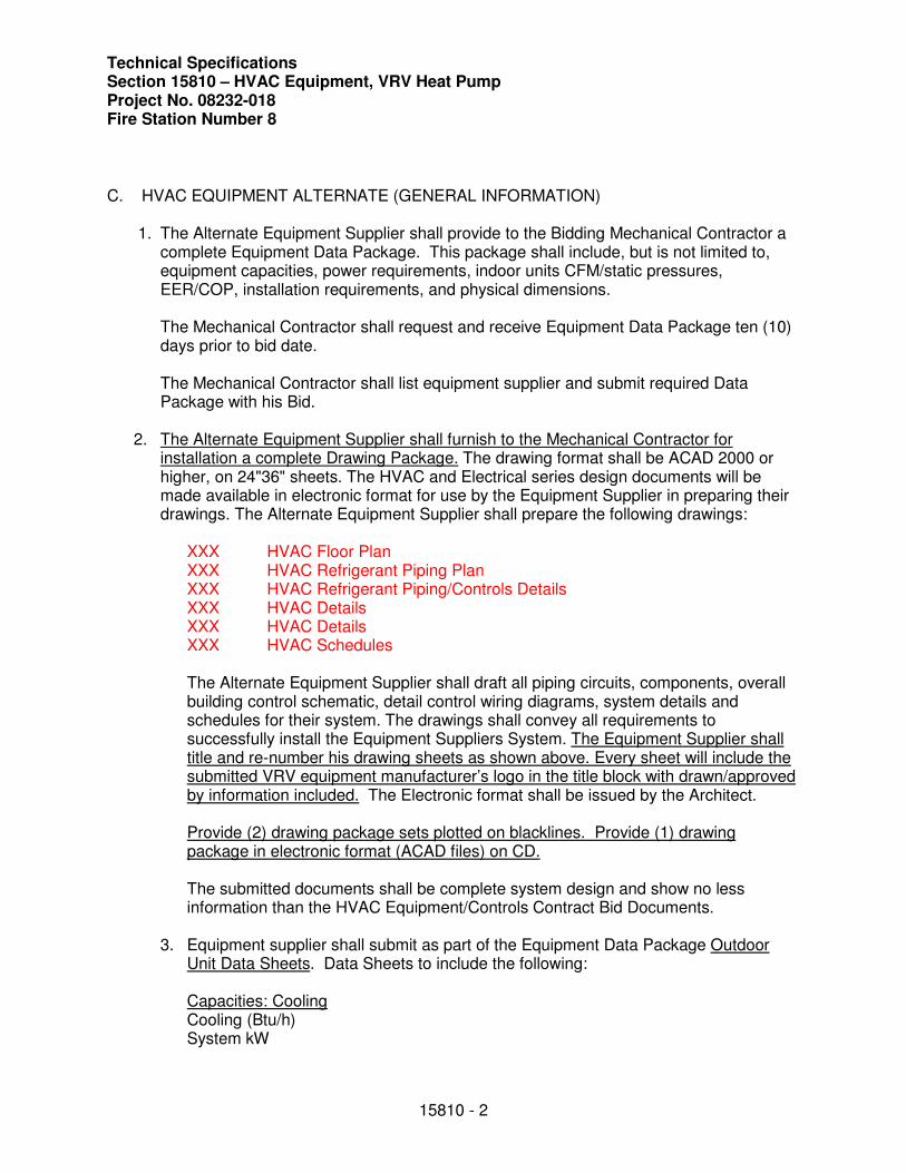
Technical Specifications Section 15810 – HVAC Equipment, VRV Heat Pump Project No. 08232-018 Fire Station Number 8
15810 - 2
C. HVAC EQUIPMENT ALTERNATE (GENERAL INFORMATION)
1. The Alternate Equipment Supplier shall provide to the Bidding Mechanical Contractor a complete Equipment Data Package. This package shall include, but is not limited to, equipment capacities, power requirements, indoor units CFM/static pressures, EER/COP, installation requirements, and physical dimensions.
The Mechanical Contractor shall request and receive Equipment Data Package ten (10) days prior to bid date.
The Mechanical Contractor shall list equipment supplier and submit required Data Package with his Bid.
2. The Alternate Equipment Supplier shall furnish to the Mechanical Contractor for installation a complete Drawing Package. The drawing format shall be ACAD 2000 or higher, on 24"36" sheets. The HVAC and Electrical series design documents will be made available in electronic format for use by the Equipment Supplier in preparing their drawings. The Alternate Equipment Supplier shall prepare the following drawings:
XXX HVAC Floor Plan XXX HVAC Refrigerant Piping Plan XXX HVAC Refrigerant Piping/Controls Details XXX HVAC Details XXX HVAC Details XXX HVAC Schedules
The Alternate Equipment Supplier shall draft all piping circuits, components, overall building control schematic, detail control wiring diagrams, system details and schedules for their system. The drawings shall convey all requirements to successfully install the Equipment Suppliers System. The Equipment Supplier shall title and re-number his drawing sheets as shown above. Every sheet will include the submitted VRV equipment manufacturer’s logo in the title block with drawn/approved by information included. The Electronic format shall be issued by the Architect.
Provide (2) drawing package sets plotted on blacklines. Provide (1) drawing package in electronic format (ACAD files) on CD.
The submitted documents shall be complete system design and show no less information than the HVAC Equipment/Controls Contract Bid Documents.
3. Equipment supplier shall submit as part of the Equipment Data Package Outdoor Unit Data Sheets. Data Sheets to include the following:
Capacities: CoolingCooling (Btu/h) System kW
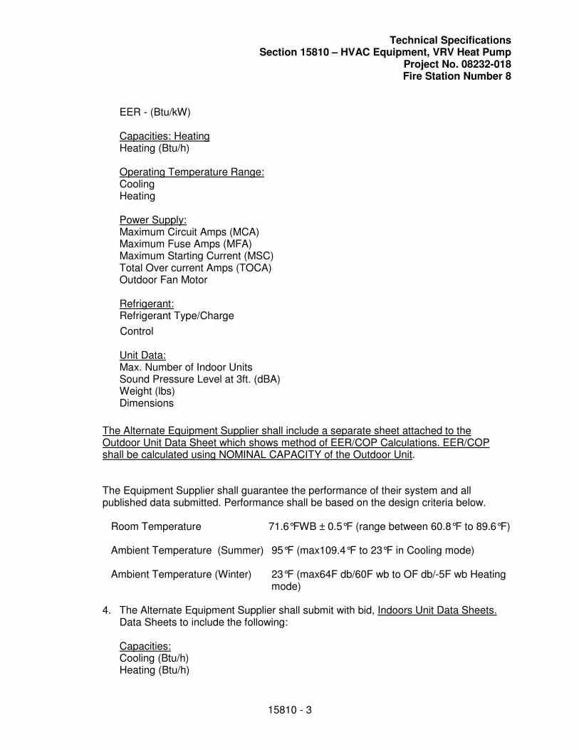
Technical Specifications Section 15810 – HVAC Equipment, VRV Heat Pump
Project No. 08232-018 Fire Station Number 8
15810 - 3
EER - (Btu/kW)
Capacities: HeatingHeating (Btu/h)
Operating Temperature Range: Cooling Heating
Power Supply:Maximum Circuit Amps (MCA) Maximum Fuse Amps (MFA) Maximum Starting Current (MSC) Total Over current Amps (TOCA) Outdoor Fan Motor
Refrigerant:Refrigerant Type/Charge
Control
Unit Data: Max. Number of Indoor Units Sound Pressure Level at 3ft. (dBA) Weight (lbs) Dimensions
The Alternate Equipment Supplier shall include a separate sheet attached to the Outdoor Unit Data Sheet which shows method of EER/COP Calculations. EER/COP shall be calculated using NOMINAL CAPACITY of the Outdoor Unit.
The Equipment Supplier shall guarantee the performance of their system and all published data submitted. Performance shall be based on the design criteria below.
Room Temperature 71.6°FWB ± 0.5°F (range between 60.8°F to 89.6°F)
Ambient Temperature (Summer) 95°F (max109.4°F to 23°F in Cooling mode)
Ambient Temperature (Winter) 23°F (max64F db/60F wb to OF db/-5F wb Heating mode)
4. The Alternate Equipment Supplier shall submit with bid, Indoors Unit Data Sheets. Data Sheets to include the following:
Capacities: Cooling (Btu/h) Heating (Btu/h)
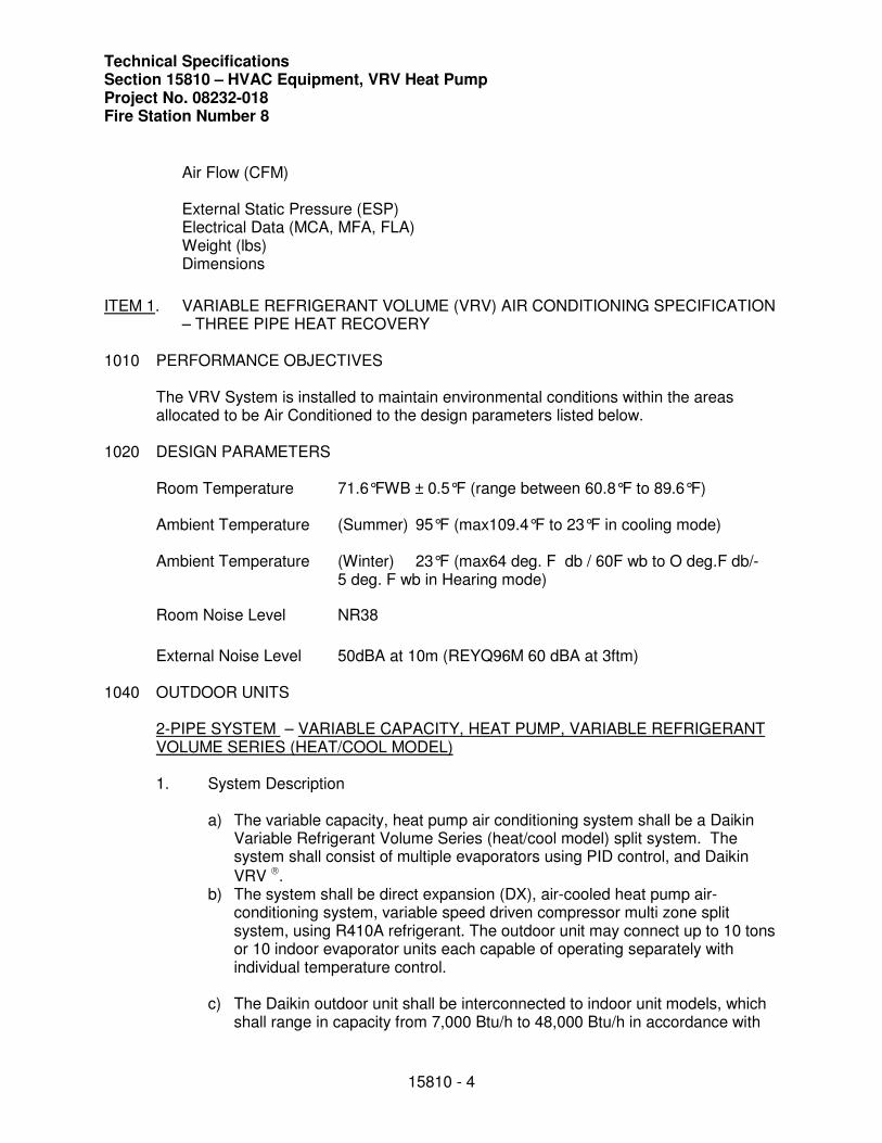
Technical Specifications Section 15810 – HVAC Equipment, VRV Heat Pump Project No. 08232-018 Fire Station Number 8
15810 - 4
Air Flow (CFM)
External Static Pressure (ESP) Electrical Data (MCA, MFA, FLA) Weight (lbs) Dimensions
ITEM 1. VARIABLE REFRIGERANT VOLUME (VRV) AIR CONDITIONING SPECIFICATION – THREE PIPE HEAT RECOVERY
1010 PERFORMANCE OBJECTIVES
The VRV System is installed to maintain environmental conditions within the areas allocated to be Air Conditioned to the design parameters listed below.
1020 DESIGN PARAMETERS
Room Temperature 71.6°FWB ± 0.5°F (range between 60.8°F to 89.6°F)
Ambient Temperature (Summer) 95°F (max109.4°F to 23°F in cooling mode)
Ambient Temperature (Winter) 23°F (max64 deg. F db / 60F wb to O deg.F db/- 5 deg. F wb in Hearing mode)
Room Noise Level NR38
External Noise Level 50dBA at 10m (REYQ96M 60 dBA at 3ftm)
1040 OUTDOOR UNITS
2-PIPE SYSTEM – VARIABLE CAPACITY, HEAT PUMP, VARIABLE REFRIGERANT VOLUME SERIES (HEAT/COOL MODEL)
1. System Description
a) The variable capacity, heat pump air conditioning system shall be a Daikin Variable Refrigerant Volume Series (heat/cool model) split system. The system shall consist of multiple evaporators using PID control, and Daikin
VRV . b) The system shall be direct expansion (DX), air-cooled heat pump air-
conditioning system, variable speed driven compressor multi zone split system, using R410A refrigerant. The outdoor unit may connect up to 10 tons or 10 indoor evaporator units each capable of operating separately with individual temperature control.
c) The Daikin outdoor unit shall be interconnected to indoor unit models, which shall range in capacity from 7,000 Btu/h to 48,000 Btu/h in accordance with
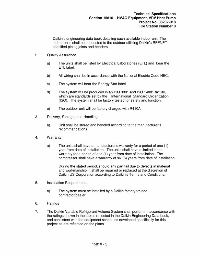
Technical Specifications Section 15810 – HVAC Equipment, VRV Heat Pump
Project No. 08232-018 Fire Station Number 8
15810 - 5
Daikin’s engineering data book detailing each available indoor unit. The indoor units shall be connected to the outdoor utilizing Daikin’s REFNET specified piping joints and headers.
2. Quality Assurance
a) The units shall be listed by Electrical Laboratories (ETL) and bear the ETL label.
b) All wiring shall be in accordance with the National Electric Code NEC.
c) The system will bear the Energy Star label.
d) The system will be produced in an ISO 9001 and ISO 14001 facility, which are standards set by the International Standard Organization (ISO). The system shall be factory tested for safety and function.
e) The outdoor unit will be factory charged with R410A
3. Delivery, Storage, and Handling
a) Unit shall be stored and handled according to the manufacturer’s recommendations.
4. Warranty
a) The units shall have a manufacturer’s warranty for a period of one (1) year from date of installation. The units shall have a limited labor warranty for a period of one (1) year from date of installation. The compressor shall have a warranty of six (6) years from date of installation.
During the stated period, should any part fail due to defects in material and workmanship, it shall be repaired or replaced at the discretion of Daikin US Corporation according to Daikin’s Terms and Conditions.
5. Installation Requirements
a) The system must be installed by a Daikin factory trained contractor/dealer.
6. Ratings
7. The Daikin Variable Refrigerant Volume System shall perform in accordance with the ratings shown in the tables reflected in the Daikin Engineering Data book, and consistent with the equipment schedules developed specifically for this project as are reflected on the plans.
Technical Specifications Section 15810 – HVAC Equipment, VRV Heat Pump Project No. 08232-018 Fire Station Number 8
15810 - 6
a) The operating range in cooling will be 23°F DB ~ 110°F DB. The operating range in heating will be 0°F DB ~ 60°F DB.
8. Refrigerant Piping
a) The system shall be capable of refrigerant piping up to 490 equivalent feet, a total combined length of 1000 feet of piping between the condensing and fan coil units with 165 feet maximum vertical difference, without any oil traps or additional equipment. In case where the outdoor unit is located below the indoor unit, the vertical difference is a maximum of 90 feet.
9. Outdoor Unit
a) General: The outdoor unit is designed specifically for use with VRV series components.
1) The outdoor unit shall be factory assembled and pre-wired with all necessary electronic and refrigerant controls. The refrigeration circuit of the condensing unit shall consist of a Daikin scroll compressor, motors, fans, condenser coil, electronic expansion valve, solenoid valves, 4 way valve, distribution headers, capillaries, filters, shut off valves, oil separators, service ports, liquid receivers and accumulators.
2) Both liquid and suction lines must be individually insulated between the outdoor and indoor units.
3) The outdoor unit can be wired and piped with outdoor unit access from left, right, rear or bottom.
4) The connection ratio of indoor units to outdoor unit will be 50% to 125%.
5) The sound pressure dB(A) shall be a value of 58 decibels at 3 feet. The outdoor unit shall be capable of operating at further reduced noise during night time.
6) The system will automatically restart operation after a power failure and will not cause any settings to be lost, thus eliminating the need for re-programming.
7) The outdoor unit shall be modular in design and should allow for side-by-side installation with minimum spacing. It should possible for no more than 3 separate condensing units to be connected to one piping system.
Technical Specifications Section 15810 – HVAC Equipment, VRV Heat Pump
Project No. 08232-018 Fire Station Number 8
15810 - 7
8) The following safety devices shall be part of the condensing unit; high pressure switch, control circuit fuses, crankcase heaters, fusible plug, high pressure switch, overload relay, inverter overload protector, thermal protectors for compressor and fan motors, over current protection for the inverter and anti-recycling timers. To ensure the liquid refrigerant does not flash when supplying to the various fan coil units, the circuit shall come with a sub-cooling feature. Oil recovery cycle shall be automatic occurring 1 hour after start of operation and then every 6 hours of operation.
9) In the case of a system comprising of plural condensing units, it is required that the condenser unit with the lowest inverter compressor running time be the first to operate at each start up. This duty cycling feature shall be factory supplied.
10) The outdoor unit shall be capable of operation at 0°F Dry bulb ambient temperature without additional low ambient controls.
b) Unit Cabinet:
1) The outdoor unit shall be completely weather proof and corrosion resistant. The unit shall be constructed from rust-proofed mild steel panels coated with a baked enamel finish.
c) Fan:
1) The condensing unit shall consist of two propeller type, direct-drive fan 750 W motors that have multiple speed operation of the DC inverter type.
2) The condensing unit fan motor shall have multiple speed operation of the DC inverter type, and be of high external static pressure and shall be factory set as standard at 0.12 in. WG with available by field setting switch to a maximum 0.25 in. WG pressure.
3) The fan shall be a vertical discharge configuration with an air flow
of 7,400 cfm.
4) The fan motor shall have inherent protection and permanently lubricated bearings and be mounted.
5) The fan motor shall be provided with a fan guard to prevent contact with moving parts.
d) Condenser Coil:
Technical Specifications Section 15810 – HVAC Equipment, VRV Heat Pump Project No. 08232-018 Fire Station Number 8
15810 - 8
1) The condenser coil shall be manufactured from copper tubes expanded into aluminum fins to form a mechanical bond.
2) The coil shall be of a waffle louver fin and high heat exchanger, rifled bore tube design to ensure highly efficient performance.
3) The coils shall be complete with corrosion treatment of an acrylic resin type. The thickness of the coating must be between 2.0 to 3.0 microns.
e) Compressor:
1) The Daikin scroll compressor shall be variable speed (PAM inverter) controlled which is capable of changing the speed to follow the variations in total cooling load as determined by the suction gas pressure as measured in the condensing unit.
2) The inverter driven compressor in each condensing unit shall be of highly efficient reluctance DC, hermetically sealed scroll type with a max speed of 6,480 rpm.
3) Neodymium magnets shall be adopted in the rotor construction to yield a higher torque and efficiency in the compressor instead of the normal ferrite magnet type. At complete stop of the compressor, the neodynium magnets will position the rotor into the optimum position for a low torque start.
4) The capacity control range shall be 14% to 100%. Each non-inverter compressor shall also be of the hermetically sealed scroll type.
5) Each compressor shall be equipped with a crankcase heater, high pressure safety switch, and internal thermal overload protector.
6) Oil separators shall be standard with the equipment together with an oil balancing circuit.
7) The compressor shall be mounted to avoid the transmission of vibration.
f) Electrical:
1) The power supply to the outdoor unit shall be 208/230 volts, 3 phase, 60 hertz with a voltage range from 187 volts to 253 volts.
Technical Specifications Section 15810 – HVAC Equipment, VRV Heat Pump
Project No. 08232-018 Fire Station Number 8
15810 - 9
2) The control voltage between the indoor and outdoor unit shall be 16VDC non-shielded 2 conductor cable.
3) The control wiring shall be a two-wire multiplex transmission system, making it possible to connect multiple indoor units to one outdoor unit with one 2-cable wire, thus simplifying the wiring operation.
4) The control wiring lengths are:
Outdoor to Indoor
Unit Outdoor to Central
Controller Outdoor Unit to Remote Control
Control Wiring Length
6,665 3,330 1,665
Wire Type 2 wire, non-polarity, non-shielded
10. Microprocessor Control
a. Automatic system-oriented setting controls, for example identification of connected indoor units. Very fast “wiring check” for field cabling (approx. 10-20 mins). Modification of programmed factory settings for evaporation, condensation and defrost temperature and also sequence start-up, noise reduction for reduced nighttime operation. Selection of master or slave functions when outdoor units are connected in groups. Interface for service and diagnosis computers, allowing full system visualization and data logging in 1.44-megabyte data format.
b. CE compliance certificates comprising LVD73/23/EEC, EMV89/336/EEC and MSD89/392/EEC supplied with the unit.
c. Operating range in cooling mode from 23F to 109F, heating mode from 5 F to 59 F.
d. VRV Installation guidelines for test site units working on R410A
1045 OUTDOOR UNITS – MINI VRV
1. The system shall be air-cooled, split type multi system air conditioners as manufactured by DAIKIN Industries Limited in Japan. The equipment shall consist of singular condensing units connecting to multiple fan coil units, each having capability to condition independently for the requirements of the room.
2. The condensing unit shall be able to connect multiple different type and capacity fan coil units to be controlled individually. The Condensing Unit shall be equipped with Inverter Controller, allowing the system to operate at a minimum connected cooling load of 2.2kW The COP of the system at 50% partial load shall be 3.5 or better.
Technical Specifications Section 15810 – HVAC Equipment, VRV Heat Pump Project No. 08232-018 Fire Station Number 8
15810 - 10
3. Compressor
The compressor shall be of the high-efficiency Hermetically Sealed Reluctance DC (Digital Commutator brushless motor) Scroll type employing neodymium magnets with gas fed directly to the compression process. The motor is cooled by pressurized gas and has no accumulator.
The outdoor unit shall have one inverter driven compressor electronically controlled and capable of changing the speed linearly to follow the variations in cooling or heating load. In the cases of two or more compressors there shall be duty balancing. This shall be by the use of HIDECS circuit (Hi Inverter Drive and Electronics Control System) together with independent multi-variable PI (Proportional Integral) control for the precise monitoring of status of the system.
Capacity control of the outdoor unit shall be inverter controlled with a min of 20 steps, then with by-pass for minimum capacity control of 8%. The frequency of inverter control shall be determined electronically by sensing ambient temperatures, operational pressures and monitoring the exact requirement of all of the connected indoor units.
4. The system shall be capable of refrigerant piping up to 330 ft. between the condensing and fan coil units with 165ft. level difference, without any oil traps or additional equipment. In case where the outdoor unit is located under the indoor unit, the level difference is a maximum of 133ft.
5. Both the fan coil units and condensing unit shall be factory assembl and tested at the factory. Additionally, the condensing unit will be charged with refrigerant at the factory.
1050 INDOOR UNITS
The basic components of the indoor units are a fan, a heat exchanger and an electronic proportional expansion valve which shall be controlled via computerized PID control which constantly, every 20 seconds measures and assesses the status of the return air temperature, refrigerant inlet and outlet temperature.
The indoor units shall be selected from the following types of Daikin units using R410A:
Slim Concealed Mounted Built-Type FXDQ-M Wall Mounted Type FXAQ-M
See plans for details of equipment selected.
Technical Specifications Section 15810 – HVAC Equipment, VRV Heat Pump
Project No. 08232-018 Fire Station Number 8
15810 - 11
During the cooling operation the electronic expansion valve shall control the degree of refrigerant superheat at the evaporator outlet. During the heating operation it shall control the degree of refrigerant sub cooling at the condenser outlet.
The indoor unit printed circuit board shall be complete with power input fusing, address switches for a variety of operation controls, emergency operation switch and fault/operation indication LED's. Fan motors shall be thermally protected.
The indoor unit casing of ceiling concealed and cassette types, shall be fully insulated and sealed to prevent condensation. The insulation shall conform to local regulations.
1060 LOCAL SYSTEM CONTROLS
The controls system shall include all necessary Daikin remote controllers and interface PCB's.
One simplified remote controller (BRC2A71) shall be provided per room or fan coil as specified and be capable of controlling an individual fan coil or group of fan coils, up to 16 indoor units. Functions available to the students / teachers can be blocked.
The controller shall have a liquid crystal display and provide the following facilities:
• Temperature setting
• Fan speed setting
• Mode setting fan/cooling
• On/Off control
• Diagnostics Feedback ( 55 alarm codes)
Remote air sensors KRCS01-1 shall be provided for local room sensing where fresh air is introduced to the fan coil unit. To be positioned within the room or close to the return air grill in the ceiling.
1100 FACTORY START UP
The Equipment Supplies representative shall carry out/or witness the commissioning of the VRV system and final inspection and record data as listed below:
• Record Pressure Test (Holding Pressure)
• Confirmation of Record Drawings
• Record Pipe Lengths
• Record Pipe Diameters
• Additional and Total refrigerate Volumes
• Addressing of Fan Coils
• Cooling Start Up Check
• Heating Start Up Check
• Complete and issue Documents and Certificates to Consultant/Client.
Technical Specifications Section 15810 – HVAC Equipment, VRV Heat Pump Project No. 08232-018 Fire Station Number 8
15810 - 12
Should it deemed necessary full access should be afforded to the site during the installation of the VRV System to allow the Equipment Supplier’s representative/engineer to verify that the installation methods being used comply and are fully in accordance with the VRV System Installation Instructions, requirement in order that the equipment warranties will not be invalidated.
COPPER PIPING for R410A
1. GENERAL
a) The refrigerant pipe shall be of de-oxidized phosphorous seamless copper pipe conforming to JIS H300-C1220T. Both suction gas and liquid lines should be sufficiently insulated to prevent formation of condensation in all circumstances. These pipes will be brazed with hard `Silver ` solder. Copper Piping for R410A Soldering work should avoid any upward direction in order to avoid leakage. The recommendable oil for pipe processing must be a synthetic oil (ether oil, ester oil, alkyl benzene oil or a mixture of these).
b) Tools used for R410A like gauges, gas leak detector, vacuum pump should be dedicated for R410A and cannot be used for R22 to avoid mineral oil contamination.
c) Piping size selection and only R410A refnets will be used and selected according to DAIKIN specifications.
d) The 3 rules of refrigerant piping: Dry, Clean and Airtight must be strictly observed during the piping work. At all times pipes should be covered or even pinched to avoid moisture.
e) Flushing both gas and liquid pipes with Nitrogen will be used as a standard working practice.
2. Thermal Insulation
a. The thermal insulation materials used must be well able to withstand the heat from the pipes and the local fire protection codes. The insulation of jointed pipes such as soldered, flared or flanged sections should only be carried out after the successful completion of the airtight test.
b. Attention should be paid to the unit model and the operating conditions. Liquid and suction pipe runs have to be insulated. Thickness of insulation material for pipe sections up to 1” insulation thickness should be minimum ½”, for larger pipe sections >1” the thickness should be increased to 5/8” or larger.
Technical Specifications Section 15810 – HVAC Equipment, VRV Heat Pump
Project No. 08232-018 Fire Station Number 8
15810 - 13
c. When the VRV system will operate at external temperatures below 50F the liquid pipe runs have to be insulated.
3. Flare Connection
a. A pipe cutter will be used to cut the pipe, burrs should be removed carefully. Flare sizes, as determined in SI 62
b. Appropriate amount of torque will be used to tighten the flare nut, ref SI62. Two Spanners should be used to grip the pipe.
4. Flange connection on Outdoor unit
a. The flange must be clean and undamaged; the flange surface should be coated with non-mineral refrigeration oil before the bolts are tightened.
5. Refnets
a. The selected refnet joints shall be installed horizontally or within an angle of 30 degrees.
b. The thermal insulation delivered with the joints must be used.
c. If selected pipe differs form the branch pipe in size, the correct pipe section must be cutted on the refnet.
d. The selected refnet headers can only be installed horizontally and they must be correctly insulated after the airtight test.
6. Refrigerant charge
a. The Daikin calculation method, based on `as-built` piping lengths, will be used before charging. After the airtight test, where a pressure of 3.2 M PA cannot decrease for 24hrs a double step vacuum drying will be executed. Small minor leaks cannot be detected if the pressure test is not executed for at least 24hrs.If there is no drop in pressure the test is OK.
b. In case of pressure drop the possible leak has to be detected by pressurizing with N2.
c. After the leak test the vacuum drying method in 2 steps will be executed. First vacuum drying will be done for 2 hours, vacuum will be broken with N2 only, a second vacuum test will be executed until the vacuum grade is –755 mmHg or lower is reached, the vacuum will be broken the charging process can be started.
d. R410A will be charged in liquid phase using a weighing scale + dedicated gauge manifold and charging hose. The added amount of refrigerant will be recorded on
Technical Specifications Section 15810 – HVAC Equipment, VRV Heat Pump Project No. 08232-018 Fire Station Number 8
15810 - 14
the outdoor unit.
e. Local codes with reference to possible refrigerant leakage must be respected. 7. Fan Coil Units
a. Each type of indoor unit requires level installation and easy access to filters for replacement and to electronics/drain pump for maintenance.
b. Special caution for short circuit has been taken into account. When fan coil units will be integrated into a false ceiling, enough ceiling height must be available.
c. Local codes apply for installing ductwork to a ducted indoor unit.
8. Drain piping
a. All indoor units equipped with a drain pump require the installation of the flexible drain hose and clamp delivered with the fan coil unit. This drain hose will be connected to the drainpipes that will have a downward slope of 1/100. The working of the drain pump can be tested by using the test mode of the fan coil unit and adding water in the drain pan .The drain pipe should be at least equal in size to that of the fan coil unit and thermally insulated to prevent any condensation.
b. All fan coil units whose drain connection is subjected to negative pressure should be fitted with an individual drain trap; this trap must allow future cleaning.
c. Ducted units shall be provided with an external condensate pump when gravity fall is not sufficient. Pump shall interlock with indoor unit.
9. Control Wiring
a. All field wiring and components must be provided by a licensed electrician.
b. The units shall be grounded in compliance with the applicable local and national codes.
c. The control system shall be connected by using non-polarity, 2-wire multiplex transmission system links from the single outdoor unit to multiple indoor units. In addition, the control system must come equipped with automatic address setting function (No manual setting of addressing is allowed). An automatic checking function for connection error of wiring and piping must come standard with the system.
d. The fan coil units shall functionally incorporate an on/off switching, fan speed selector, thermostat setting and liquid crystal display which indicates temperature setting, operational mode, malfunction code and filter cleaning timing. The
Technical Specifications Section 15810 – HVAC Equipment, VRV Heat Pump
Project No. 08232-018 Fire Station Number 8
15810 - 15
controller shall retain the latest malfunction code for maintenance, capable of field setting and service functions.
e. This shall be accomplished by the use of individual controllers for each room located on a wall in appropriate room temperature sensing location.
f. Multi core cables can destabilize the transmitted wave of the multiplex signal. High voltage wiring (power supply indoor units) should not be mixed with low voltage wiring (F1F2 communication line) .The separation of power and control lines is specified and these distances should be respected in order to avoid interference.
g. Refrigerant circuit and indoor/outdoor communication lines must correspond exactly.
10. Power Supply
Condensing units: 208 V / 3phase / 60 Hz Fan Coil units: 208 V / 1 phase / 60 Hz
a. Condensing Unit: a separate breaker of 70 A must be fitted for each outdoor unit. The thickness of the cables in the circuits providing the main power supply must satisfy the current tolerances specified by local code and by Daikin (SI 62).
b. Fan Coil Units: a separate breaker 15 A per indoor unit according to local code. If several indoor units are connected to one breaker, the total rated capacity of the fan motors set up in a 15A branch should not be more then 2.2 kW.
ITEM 2 – CONTROLS SPECIFICATION
A. GENERAL
The Mechanical Contractor shall be responsible to provide devices needed to bring all HVAC equipment, exhaust fans, etc. shown on the plans and specifications under EMS control.
The Equipment Supplier Shall provide to the Mechanical Contractor interface control adaptors (DTA103A51) to allow control of all Fresh Air units (ERV), and exhaust fans. The adaptor shall provide the following functions: unified ON/OFF control, timer operation, remote controller rejection/acceptance and operating status and adjustment.
B. CONTROLLER
1. Provide multi-zone controller DCS302C71.
C. QUALITY ASSURANCE
Technical Specifications Section 15810 – HVAC Equipment, VRV Heat Pump Project No. 08232-018 Fire Station Number 8
15810 - 16
1. Codes and Standards: Meet requirements of all applicable standards and codes, except when more detailed or stringent requirements are indicated by the Contract Documents, including requirements of this Section.
a. Underwriters Laboratories: Products shall be UL-916-PAZX listed. b. National Electrical Code -- NFPA 70. c. Federal Communications Commission -- Part J.
2. All products used in this installation shall be new, currently under manufacture, and shall be applied in similar installations for a minimum of [2] years. This installation shall not be used as a test site for any new products unless explicitly approved by the Owner's representative in writing prior to bid date. Spare parts shall be available for at least 5 years after completion of this contract.
D. SUBMITTALS
1. Equipment Supplier shall provide screen shots of unit graphics and floor plans, shop drawings and manufacturers’ standard specification data sheets on all hardware and software to be provided. No work may begin on any segment of this project until the Engineer and Owner have reviewed
submittals for conformity with the plan and specifications. Eight (8) copies are required. All shop drawings shall be provided to the Owner electronically as .dwg or .dxf file formats.
2. Quantities of items submitted shall be reviewed by the Engineer and Owner. Such review shall not relieve the Equipment Supplier from furnishing quantities required for complete installation.
3. Provide the Engineer and Owner, any additional information or data that is deemed necessary to determine compliance with these specifications or which is deemed valuable in documenting the system to be installed.
4. Submit the following:
a. A complete bill of materials of equipment to be used indicating quantity, manufacturer and model number.
b. A schedule of all control valves including the valve size, model number (including pattern and connections), flow, CV, pressure rating, and location.
c. A schedule of all control dampers. This shall include the damper size, pressure drop, manufacturer and model number.
d. Provide manufacturers cut sheets for major system components. When manufacturer's cut sheets apply to a product series rather than a specific product, the data specifically applicable to the project shall be highlighted or clearly indicated by other means. Each submitted piece of literature and drawings
Technical Specifications Section 15810 – HVAC Equipment, VRV Heat Pump
Project No. 08232-018 Fire Station Number 8
15810 - 17
shall clearly reference the specification and/or drawing that the submittal is being submitted to cover. Include:
1) Building Controllers 2) Custom Application Controllers 3) Application Specific Controllers 4) Operator Interface Computer 5) Portable Operator Workstation 6) Auxiliary Control Devices
1100 FACTORY START UP
The Equipment Supplies representative shall carry out/or witness the commissioning of the VRV system and final inspection and record data as listed below:
• Record Pressure Test (Holding Pressure)
• Confirmation of Record Drawings
• Record Pipe Lengths
• Record Pipe Diameters
• Additional and Total refrigerate Volumes
• Addressing of Fan Coils
• Cooling Start Up Check
• Heating Start Up Check
• Complete and issue Documents and Certificates to Consultant/Client.
Should it deemed necessary full access should be afforded to the site during the installation of the VRV System to allow the Equipment Supplier’s representative/engineer to verify that the installation methods being used comply and are fully in accordance with the VRV System Installation Instructions, requirement in order that the equipment warranties will not be invalidated.
END OF SECTION 15810
Technical Specifications Section 15850 – Low Pressure Sheet Metal Ductwork
Project No. 08232-018 Fire Station Number 8
15850 - 1
SECTION 15850
LOW PRESSURE SHEET METAL DUCTWORK
1.0 GENERAL
1.01 Scope: Provide complete duct systems as indicated. Systems shall include, but not be limited to, the following: Outside air, exhaust air, and air conditioning supply and return air duct systems as shown on drawings. Drawing scales prohibit the indication of all offsets, fittings, and like items; however, these items shall be installed as required for the actual project conditions at no change in contract price.
A. Items Included: This section generally includes, but is not limited to, the following major items:
1. Low pressure sheet metal ductwork.
2. Low pressure flexible ducts.
3. Duct system accessories.
a. Flexible duct connections.
b. Low pressure metal turning vanes.
c. Manual volume dampers.
d. Low pressure access doors.
1.02 Relation to Other Work: Coordinate shop drawings ordering, delivery, and placement of all items affecting the duct systems including, but not limited to, the following items: Air handling units, exhaust fans, supply fans, sound attenuators, duct mounted coils, access panels, air distribution devices, fire dampers, outside air louvers, hoods, filters, roof curbs, structural framing, roof construction, roofing, and the work of all trades to insure an orderly and timely progression of the work. Refer to the requirements of the Section entitled "Common Requirements for Mechanical Work".
1.03 Shop Drawings: Refer to Section entitled "Common Requirements for Mechanical Work". Include complete data on: All prefabricated duct and fittings; access doors; flexible connectors; manual volume dampers including operating hardware; extractors; turning vanes; automatic shutters; duct liner including mechanical fasteners and adhesives; and all other items.
1.04 Air Handling Unit and Ductwork Configuration Shop Drawings:
A. Air handling unit manufacturer and model or series, which has been used as the design basis for this project, is indicated. If Contractor elects to submit for approval any unit which is made by any other manufacturer which is listed as acceptable, the Contractor shall submit a shop drawing for each air handling unit for which he proposes to use a unit which is different than the design basis. Such shop drawings shall meet the following requirements:
Technical Specifications Section 15850 – Low Pressure Sheet Metal Ductwork Project No. 08232-018 Fire Station Number 8
15850 - 2
1. Be drawn at the same scale as the unit is shown on the Drawings. Contractor may elect to use a larger scale if he desires (i.e., if drawing of unit is at 1/4" = 1'-0", 1/2" = 1'-0" may be used).
2. Clearly show all proposed ductwork configuration changes (sizes, routing, and similar differences) which are different in any respect from the Drawings. Extent of shop drawings shall show all ductwork to and from each unit beginning with and terminating at those points where ductwork is intended to remain unchanged as shown on Drawings.
3. Where proposed changes affect any other work such as structure, housekeeping pads, piping, equipment, electrical work or any other work, shop drawings shall clearly show those proposed changes.
4. Proposed changes shall be at no additional change in contract price.
5. Where Drawings show units in plan only, shop drawings shall show proposed units in plan and also in elevation.
6. Shop drawings shall also show exact locations of related work (such as bar joists, columns, beams, sound attenuators, and like items) which affect the proposed ductwork routing and unit location and configuration.
7. Each section of each air handling unit shall be clearly identified (i.e., coil section, fan section, filter section, mixing box section, etc.).
B. Failure to submit these shop drawings together at the same time with the air handling unit shop drawings will result in total disapproval of the proposed air handling units. Time delays or other reasons will not be considered.
C. These shop drawings shall be prepared as work of this section in coordination with the work of section describing the air conditioning unit(s).
1.05 Other Requirements:
A. Provide all ductwork and components thereof in accordance with manufacturer's instructions.
B. All ductwork dimensions indicated are nominal free clearance internal dimensions, which do not include insulation thickness.
1.06 Definitions:
A. "SMACNA" means "Sheet Metal and Air Conditioning Contractors' National Association, Inc."
B. Low Pressure Ductwork: Any and all ductwork conveying air or other gases at velocities less than 2000 fpm and static pressure less than 2.0 inches w.g. This ductwork may also be referred to in these specifications as "Low Velocity Ductwork". SMACNA "HVAC Duct Construction Standards, Metal and Flexible,"
Technical Specifications Section 15850 – Low Pressure Sheet Metal Ductwork
Project No. 08232-018 Fire Station Number 8
15850 - 3
First Edition, 1985, shall govern construction of this ductwork unless otherwise specified; construct duct in accord therewith.
C. Pressure and Velocity Classifications: Pressure and velocity classifications, (hereinafter called "P/VC") for ducts are defined as follows:
Positive
SMACNA Static or SMACNA
P/VC Pressure Pressure Negative Seal Velocity
Designation Class Rating Pressure Class (fpm)
2 Low 2" + or - B 2500 dn
1 Low 1" + or - C 2500 dn
1/2 Low 1/2" + or - D 2000 dn
Note: All seams, joints, fastener penetrations and connections to be sealed with hard cast.
2.0 PRODUCTS
2.01 Low Pressure Sheet Metal Ductwork: Systems operating at two inches of water static pressure or less, shall, unless specifically specified otherwise, conform to the following requirements:
A. Material: Prime quality forty-eight inch wide resquare tight coat galvanized steel conforming to the requirements of ASTM A-526.
B. Reinforcing, Cross Breaking, Seams, Joints: Be in accordance with latest SMACNA construction standard for low-pressure sheet metal duct.
2.03 Glass Fiber Low Pressure Ductwork: None allowed on this project.
2.04 Low Pressure Round Ductwork:
A. Conduit: Shall be "zinc grip" steel of spiral lock-seam construction. Duct shall be made using galvanized steel as per ASTM A-527 G-90. Gauge shall be as follows:
1. Round Duct:
FittingSize Duct Gauge GaugeUp through 8"diameter 26 gauge 24 gauge 9" through 14" diameter 26 gauge 24 gauge 15" through 26" diameter 24 gauge 22 gauge 27" through 36" diameter 22 gauge 20 gauge 37" through 50" diameter 20 gauge 20 gauge 51" through 60" diameter 18 gauge 18 gauge 61" through 84" diameter 16 gauge 16 gauge
Technical Specifications Section 15850 – Low Pressure Sheet Metal Ductwork Project No. 08232-018 Fire Station Number 8
15850 - 4
2.05 Low Pressure Flexible Ducts: Flexible duct shall consist of spiral wound Helix Coil with Trilaminate Inner Fabric. Core shall be covered with factory applied one inch, one pound per cubic foot fiberglass insulation of 0.23 thermal conductance sheathed in a seamless exterior Class 1 vapor barrier jacket reinforced aluminum foil metalized jacket. Connections shall be made using quadrant dampered twist-in type fittings with extractor scoops and volume damper. Duct shall be NFPA 90A, Class 1 (UL 181), flame spread less than 25 and smoke developed less than 50. Provide in factory finished lengths not in excess of 6'-0' to make suitable connections with minimum pressure drop. Acceptable: Flexmaster, Genflex, Clevaflex or equal with "SPIN-IN" fitting with integral damper and air scoop at connection to main duct branch.
2.06 Duct System Accessories:
A. General:
1. Provide all necessary duct system accessories to assure proper balance, quiet and draftless distribution and conveyance, and minimization of turbulence, noise and pressure drop for all supply, return, and exhaust and ventilation air quantities indicated.
2. Be recommended by the manufacturer for the application.
B. Flexible Duct Connections:
1. Provided where air handlers, fans and blowers connect their ductwork.
2. At least 4 inches long.
3. Connected on each side to metal (either metal ductwork, air handling apparatus, or heavy gauge steel sleeves).
4. For use in low-pressure duct systems.
5. Ventfabrics, Inc., "Ventglas Metaledge".
C. Low Pressure Metal Turning Vanes: Provide in all elbows, bends and tees of all low velocity supply air ducts whether or not shown in detail; provide in all elbows, bends and tees of all other low velocity ducts where portions of such ducts convey air at greater than 700 fpm average velocity. Adequate rigidity and strength to be complete flutterproof; properly designed; permanently fixed type. Aluminum, or steel with corrosion resistant coating, or galvanized steel. Air foil type in all mitered elbows, mitered bends and mitered tees. Air foil type must be manufactured by Titus, Tuttle & Bailey, Anemostat, Waterloo, Metalaire, Barber-Colman, "Airturns", Tuttle & Bailey "Ducturns", or Dura-Dyne "VR" with 24 gauge rails and hollow vanes.
D. Manual Volume Dampers: (Other than those specified as being integral with each register, diffuser and other air outlet or inlet):
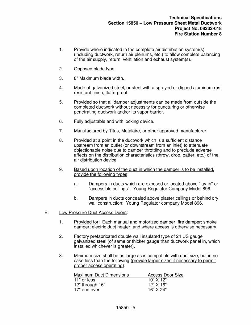
Technical Specifications Section 15850 – Low Pressure Sheet Metal Ductwork
Project No. 08232-018 Fire Station Number 8
15850 - 5
1. Provide where indicated in the complete air distribution system(s) (including ductwork, return air plenums, etc.) to allow complete balancing of the air supply, return, ventilation and exhaust system(s).
2. Opposed blade type.
3. 8" Maximum blade width.
4. Made of galvanized steel, or steel with a sprayed or dipped aluminum rust resistant finish; flutterproof.
5. Provided so that all damper adjustments can be made from outside the completed ductwork without necessity for puncturing or otherwise penetrating ductwork and/or its vapor barrier.
6. Fully adjustable and with locking device.
7. Manufactured by Titus, Metalaire, or other approved manufacturer.
8. Provided at a point in the ductwork which is a sufficient distance upstream from an outlet (or downstream from an inlet) to attenuate objectionable noise due to damper throttling and to preclude adverse affects on the distribution characteristics (throw, drop, patter, etc.) of the air distribution device.
9. Based upon location of the duct in which the damper is to be installed, provide the following types:
a. Dampers in ducts which are exposed or located above "lay-in" or "accessible ceilings": Young Regulator Company Model 896.
b. Dampers in ducts concealed above plaster ceilings or behind dry wall construction: Young Regulator company Model 896.
E. Low Pressure Duct Access Doors:
1. Provided for: Each manual and motorized damper; fire damper; smoke damper; electric duct heater; and where access is otherwise necessary.
2. Factory prefabricated double wall insulated type of 24 US gauge galvanized steel (of same or thicker gauge than ductwork panel in, which installed whichever is greater).
3. Minimum size shall be as large as is compatible with duct size, but in no case less than the following (provide larger sizes if necessary to permit proper access operating):
Maximum Duct Dimensions Access Door Size11" or less 10" X 12" 12" through 16" 12" X 16" 17" and over 16" X 24"
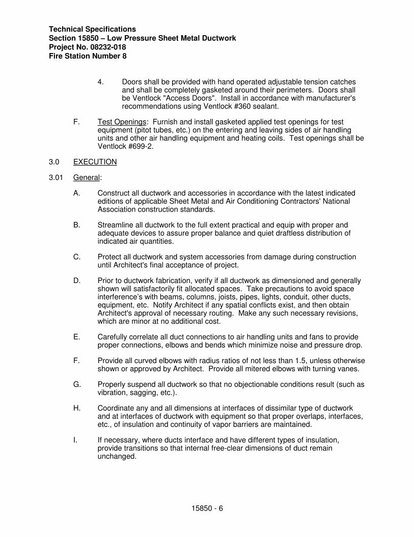
Technical Specifications Section 15850 – Low Pressure Sheet Metal Ductwork Project No. 08232-018 Fire Station Number 8
15850 - 6
4. Doors shall be provided with hand operated adjustable tension catches and shall be completely gasketed around their perimeters. Doors shall be Ventlock "Access Doors". Install in accordance with manufacturer's recommendations using Ventlock #360 sealant.
F. Test Openings: Furnish and install gasketed applied test openings for test equipment (pitot tubes, etc.) on the entering and leaving sides of air handling units and other air handling equipment and heating coils. Test openings shall be Ventlock #699-2.
3.0 EXECUTION
3.01 General:
A. Construct all ductwork and accessories in accordance with the latest indicated editions of applicable Sheet Metal and Air Conditioning Contractors' National Association construction standards.
B. Streamline all ductwork to the full extent practical and equip with proper and adequate devices to assure proper balance and quiet draftless distribution of indicated air quantities.
C. Protect all ductwork and system accessories from damage during construction until Architect's final acceptance of project.
D. Prior to ductwork fabrication, verify if all ductwork as dimensioned and generally shown will satisfactorily fit allocated spaces. Take precautions to avoid space interference’s with beams, columns, joists, pipes, lights, conduit, other ducts, equipment, etc. Notify Architect if any spatial conflicts exist, and then obtain Architect's approval of necessary routing. Make any such necessary revisions, which are minor at no additional cost.
E. Carefully correlate all duct connections to air handling units and fans to provide proper connections, elbows and bends which minimize noise and pressure drop.
F. Provide all curved elbows with radius ratios of not less than 1.5, unless otherwise shown or approved by Architect. Provide all mitered elbows with turning vanes.
G. Properly suspend all ductwork so that no objectionable conditions result (such as vibration, sagging, etc.).
H. Coordinate any and all dimensions at interfaces of dissimilar type of ductwork and at interfaces of ductwork with equipment so that proper overlaps, interfaces, etc., of insulation and continuity of vapor barriers are maintained.
I. If necessary, where ducts interface and have different types of insulation, provide transitions so that internal free-clear dimensions of duct remain unchanged.
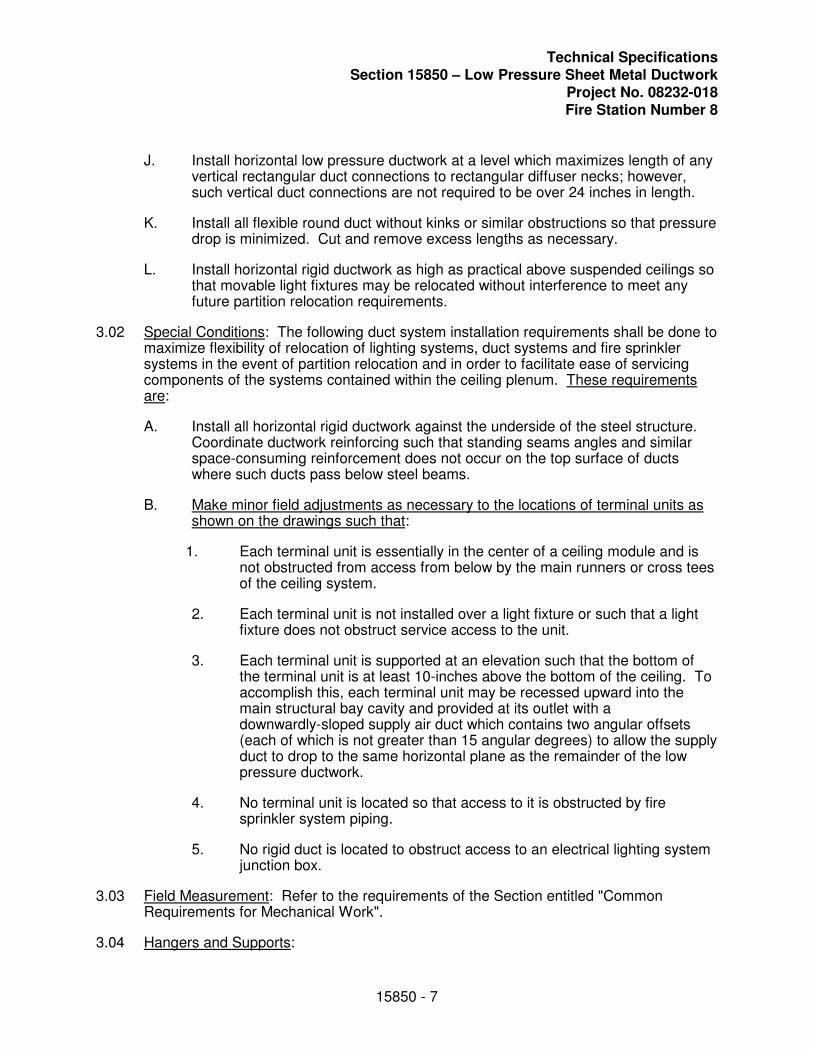
Technical Specifications Section 15850 – Low Pressure Sheet Metal Ductwork
Project No. 08232-018 Fire Station Number 8
15850 - 7
J. Install horizontal low pressure ductwork at a level which maximizes length of any vertical rectangular duct connections to rectangular diffuser necks; however, such vertical duct connections are not required to be over 24 inches in length.
K. Install all flexible round duct without kinks or similar obstructions so that pressure drop is minimized. Cut and remove excess lengths as necessary.
L. Install horizontal rigid ductwork as high as practical above suspended ceilings so that movable light fixtures may be relocated without interference to meet any future partition relocation requirements.
3.02 Special Conditions: The following duct system installation requirements shall be done to maximize flexibility of relocation of lighting systems, duct systems and fire sprinkler systems in the event of partition relocation and in order to facilitate ease of servicing components of the systems contained within the ceiling plenum. These requirements are:
A. Install all horizontal rigid ductwork against the underside of the steel structure. Coordinate ductwork reinforcing such that standing seams angles and similar space-consuming reinforcement does not occur on the top surface of ducts where such ducts pass below steel beams.
B. Make minor field adjustments as necessary to the locations of terminal units as shown on the drawings such that:
1. Each terminal unit is essentially in the center of a ceiling module and is not obstructed from access from below by the main runners or cross tees of the ceiling system.
2. Each terminal unit is not installed over a light fixture or such that a light fixture does not obstruct service access to the unit.
3. Each terminal unit is supported at an elevation such that the bottom of the terminal unit is at least 10-inches above the bottom of the ceiling. To accomplish this, each terminal unit may be recessed upward into the main structural bay cavity and provided at its outlet with a downwardly-sloped supply air duct which contains two angular offsets (each of which is not greater than 15 angular degrees) to allow the supply duct to drop to the same horizontal plane as the remainder of the low pressure ductwork.
4. No terminal unit is located so that access to it is obstructed by fire sprinkler system piping.
5. No rigid duct is located to obstruct access to an electrical lighting system junction box.
3.03 Field Measurement: Refer to the requirements of the Section entitled "Common Requirements for Mechanical Work".
3.04 Hangers and Supports:
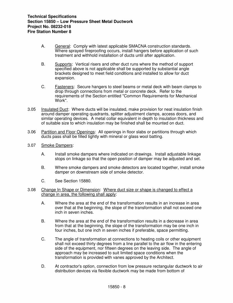
Technical Specifications Section 15850 – Low Pressure Sheet Metal Ductwork Project No. 08232-018 Fire Station Number 8
15850 - 8
A. General: Comply with latest applicable SMACNA construction standards. Where sprayed fireproofing occurs, install hangers before application of such treatment and withhold installation of ducts until after application.
B. Supports: Vertical risers and other duct runs where the method of support specified above is not applicable shall be supported by substantial angle brackets designed to meet field conditions and installed to allow for duct expansion.
C. Fasteners: Secure hangers to steel beams or metal deck with beam clamps to drop through connections from metal or concrete deck. Refer to the requirements of the Section entitled "Common Requirements for Mechanical Work".
3.05 Insulated Duct: Where ducts will be insulated, make provision for neat insulation finish around damper operating quadrants, splitter adjustment clamps, access doors, and similar operating devices. A metal collar equivalent in depth to insulation thickness and of suitable size to which insulation may be finished shall be mounted on duct.
3.06 Partition and Floor Openings: All openings in floor slabs or partitions through which ducts pass shall be filled tightly with mineral or glass wool batting.
3.07 Smoke Dampers:
A. Install smoke dampers where indicated on drawings. Install adjustable linkage stops on linkage so that the open position of damper may be adjusted and set.
B. Where smoke dampers and smoke detectors are located together, install smoke damper on downstream side of smoke detector.
C. See Section 15880.
3.08 Change In Shape or Dimension: Where duct size or shape is changed to effect a change in area, the following shall apply:
A. Where the area at the end of the transformation results in an increase in area over that at the beginning, the slope of the transformation shall not exceed one inch in seven inches.
B. Where the area at the end of the transformation results in a decrease in area from that at the beginning, the slope of the transformation may be one inch in four inches, but one inch in seven inches if preferable, space permitting.
C. The angle of transformation at connections to heating coils or other equipment shall not exceed thirty degrees from a line parallel to the air flow in the entering side of the equipment, nor fifteen degrees on the leaving side. The angle of approach may be increased to suit limited space conditions when the transformation is provided with vanes approved by the Architect.
D. At contractor's option, connection from low pressure rectangular ductwork to air distribution devices via flexible ductwork may be made from bottom of
Technical Specifications Section 15850 – Low Pressure Sheet Metal Ductwork
Project No. 08232-018 Fire Station Number 8
15850 - 9
rectangular ductwork in lieu of side connection providing contractor makes appropriate size transitions (if necessary) to maintain same free clear internal area at connection and also allows dimensional clearance for spin-in fitting with integral damper.
E. At contractor's option, he may eliminate a low pressure duct transition and hold the upstream duct size to the next downstream transition and make the necessary size transition at that point.
3.09 Changes in Direction: Changes in direction shall be basically as indicated on the drawings and the following shall apply:
A. Supply ducts turns of ninety degrees in low-pressure duct shall be made with mitered elbows fitted with closely spaced turning vanes designed for maintaining a constant velocity through the elbow.
B. Return and exhaust duct turns of ninety degrees in low pressure duct shall be made mitered elbows, as specified herein before, for supply ducts, unless radius elbows are indicated, in which case they shall be vaned and constructed with a throat radius three-quarters the duct width and a full radius heel.
C. Tees in low-pressure duct shall conform to the design requirements specified herein before for elbows.
D. Branch take-offs in low-pressure duct shall be made with extractors, splitter dampers, or 45 take-off with volume dampers, as indicated on drawings.
3.10 Other Requirements:
A. If ductwork materials are installed which do not meet these specifications, Contractor shall remove such ductwork materials and replace them with the specified materials. Any delay in job progress will be the responsibility of the Contractor.
B. Properly install all control related devices, which are part of the duct system. See Section(s) describing HVAC control systems.
END OF SECTION 15850
Technical Specifications Section 15880 – Smoke Dampers
Project No. 08232-018 Fire Station Number 8
15880 - 1
SECTION 15880
SMOKE DAMPERS
1.0 GENERAL
1.01 Work Included:
A. Smoke dampers.
B. Access doors.
1.02 Related Work:
A. Section 15000: General Conditions
B. Section 15850: Low Pressure Sheet Metal Ductwork
1.03 Reference Standards:
A. NFPA 90A.
B. SMACNA Fire, Smoke, and Radiation Installation Guide for HVAC Systems.
C. SMACNA HVAC Duct Construction Standards.
D. SMACNA Fibrous Glass Duct Construction Standards.
1.04 Submittals: Submit drawings, specifications and schedules in accordance with Section 01300 and Section 15000.
2.0 PRODUCTS
2.01 Acceptable Manufacturers:
A. National Controlled Air.
B. Ruskin.
C. Greenheck.
2.02 Construction:
A. Smoke damper: steel frame with galvanized roll formed interlocking blades 1-1/2 hour rating, with sleeve. The actuator shall permit operation by standard electric or pneumatic damper operators. Furnish with electric motor factory-mounted, 120-volt. The motor will keep the damper open with voltage applied to the motor. The damper shall close upon tripping by the smoke detector and return the damper to open position when the detection system has been cleared.
Technical Specifications Section 15880 – Smoke Dampers Project No. 08232-018 Fire Station Number 8
15880 - 2
B. Fire/Seal Access Doors: Frame, 24-gauge galvanized steel with 5/8" notched knock over edges for sheet metal or flanged frame for fiberglass duct. Door, insulated, one-inch thick double cam access, galvanized steel.
3.0 EXECUTION
3.01 Provide smoke dampers at all location shown on plans, and if not shown on plans, where ducts and outlets pass through or penetrate smoke-rated components.
3.02 Provide largest size access doors up to 16 inches by 24 inches that can be installed in the ductwork without obstruction. Provide an access door for each damper.
3.03 Install in accordance with the manufacturer's instructions.
END OF SECTION 15880
Technical Specifications Section 15980 – Test and Balance - Final
Project No. 08232-018 Fire Station Number 8
15980 - 1
SECTION 15980
TEST AND BALANCE - FINAL
1.0 GENERAL
1.01 Scope: HVAC Contractor shall provide the services of an independent test and balance agency to test, balance and certify the performance of the complete heating and air conditioning system, including supply and makeup air systems and all exhaust systems.
1.02 Job Requirements: The Contractor shall provide to the approved test and balance agency a complete set of plans and specifications and an approved copy of all heating, ventilating and air conditioning equipment shop drawings. The Contractor shall include the cost of all pulley, belt, and drive changes, as well as balancing dampers required to achieve proper system balance recommended by the test and balance agency.
1.03 Agency Qualifications: The test and balance agency shall be an approved member of AABC or NEBB that specializes in testing and balancing of heating, ventilating and air conditioning systems.
Acceptable: Test and Balance Corp. of Tampa, Phoenix Agency, Southern Independent Test and Balance, Bay to Bay Balancing, Inc. or other agency approved by Engineer.
1.04 Guarantee: The test and balance agency shall include a warranty period of ninety (90) days after completion and acceptable of test and balance work. During the warranty period, the Architect may request a re-check or re-setting of any outlet, supply fan, exhaust fan, or pump. The test and balance agency shall provide technicians, instruments, and tools to assist the Architect in conducting any test that he may require during this time. The foregoing shall be in addition to the A.A.M.C. National Project Certification Performance Guaranty which shall be forwarded with shop drawing data specified hereinbefore.
1.05 Perform all testing and balancing, adjusting and data recording necessary to establish and confirm capacity, quality and completed status of work.
2.0 PRODUCTS
2.01 Instruments used for test and balance shall have been calibrated within a period of six (6) months prior to the testing and balancing of this project. Letter of certification listing instrumentation used and last date of calibration shall be furnished to Architect with test report.
3.0 EXECUTION
3.01 National Standards: Testing and balancing shall be performed in accordance with A.A.B.C. National Standards.
3.02 Logs: Shall clearly indicate the following:
Technical Specifications Section 15980 – Test and Balance - Final Project No. 08232-018 Fire Station Number 8
15980 - 2
A. All inlet and outlet areas.
B. All applicable duct, pipe and coil sizes.
C. Outside, inside, mixed and supply air conditions.
D. All fluid velocities, flow rates, temperatures and pressures at significant locations (e.g., fluid pressures before and after each pump and fan, temperatures and pressures at supply and return headers and at chiller and boiler inlets and outlets, etc.)
E. All fan speeds.
F. All motor ampere ranges.
G. Descriptions of each test method used.
H. Use Associated Air Balance Council log and data forms.
3.03 Adjust and calibrate all applicable items (e.g., controls, dampers, registers, diffusers, balancing cocks, valves, thermometers, gauges, etc.).
3.04 Set all distribution devices to properly distribute conditioned air.
3.05 Check all safety devices for proper operation.
3.06 Verify adequacy, acceptable quietness and proper continuous operation of at least 24 hours duration of all motors, compressors, fans, etc.
3.07 Perform spot check tests or complete tests to fully reconfirm prior test results if required by the Architect as dependent upon extent, completeness and accuracy of prior tests and logs. Do in Architect's presence if called for.
3.08 After air distribution devices have been balanced to distribute calculated design indicated air quantities and if temperature in any area (where such area does not have the particular zone temperature control thermostat located therein) of any zone is not maintained within 2 degrees plus or minus of the zone area which does have the zone temperature control thermostat, then notify the Architect in writing of such conditions and obtain Architect's approval to rebalance devices to obtain air quantities other than those indicated so that air temperature in entire zone will be as even as possible regardless of calculated design air quantities. After obtaining Architect's written approval to rebalance, perform such necessary rebalancing.
3.09 When the mechanical work is in a state of readiness for test and balance work to proceed, the test and balance contractor shall proceed with his work. If, upon this proceeding, the test and balance contractor determines that there are other items of the work (control items, sheet metal items and/or other similar specialties and proper completion of which affects the ability of the test and balance contractor to properly perform his work) which have not been completed to an extent which will allow him to
Technical Specifications Section 15980 – Test and Balance - Final
Project No. 08232-018 Fire Station Number 8
15980 - 3
complete test and balance work, then he shall make a detailed written report of these items and shall send written notification to the Contractor of such incomplete work. The Contractor shall then send a copy of this report to the Architect. The test and balance work shall not proceed until these items are corrected; such correction shall be subject to approval of Architect.
3.10 All mechanical systems shall be balanced to optimum performance capabilities of the equipment and the design. This shall be done in accordance with the standards published by the Associated Air Balance Council unless otherwise indicated.
3.11 Report: Upon completion of all testing and balancing and prior to requesting final inspection and acceptance of the project, submit three (3) complete copies of the Test and Balance Report to the Architect/Engineer for approval. No final inspection will be conducted until the final Test and Balance Report has been accepted by the Engineer. Measurements shall be taken by methods recommended in the AABC (Associated Air Balance Council) National Standards. All reports submitted for review shall contain all of the information required in the reports shown in the related chapters of the AABC National Standards.
END OF SECTION 15980
Technical Specifications Section 15995 – HVAC System Commissioning
Project No. 08232-018 Fire Station Number 8
15995-1
SECTION 15995
HVAC SYSTEM COMMISSIONING
1.0 GENERAL
1.01 GENERAL PROVISIONS
A. Drawings and general provisions of the Contract, including General Conditions and Division-1 Specifications Sections, apply to work of this section.
B. Provisions of Section 15000, Basic Mechanical Requirements shall be made an integral part of this Section.
C. As a minimum the contractor will refer to following Sections; 15000, 15005, 15020, 15130, 15190, 15200, 15201, 15210, 15211, 15215, 15220, 15224, 15305, 15400, 15601, 15605, 15662, 15800, 15810, 16741. Provisions of these sections shall be made an integral part of this section.
D. Refer to ASHRAE Guideline 1-1996, The HVAC Commissioning Process, as a reference for commissioning.
1.02 WORK INCLUDED
A. Participate in the Commissioning program as outlined in this section.
1.03 COMMISSIONING PROGRAM CRITERIA
A. Intent
1. The intent of HVAC Commissioning Program is to assure delivery to the Owner, HVAC systems that are fully functioning in accordance with all specifications and which the Owner's personnel are fully trained and equipped to operate, maintain and troubleshoot.
2. The Commissioning Program shall be prepared by the Owner's Commissioning Authority in conjunction with the Contractor.
3. The Contractor shall execute a Commissioning Program that delivers the intended results using whatever personnel, time and resources are required.
4. This Section provides minimum program requirements; however, the Contractor shall exceed those requirements whenever necessary to achieve the intent of the HVAC Commissioning Program.
Technical Specifications Section 15995 – HVAC System Commissioning Project No. 08232-018 Fire Station Number 8
15995-2
B. Commissioning Authority:
1. The Owner shall retain a Commissioning Authority that shall prepare, coordinate and oversee all aspects of the program and to ensure that all steps as outlined in this section are carried out.
2. The Commissioning Authority shall report to the Owner.
C. Definitions and Abbreviations:
1. Maintenance, Orientation and Inspection: At prescribed times during the Work, the Contractor will walk the Owner’s Operations and Maintenance personnel through the Work, orient them to equipment types and locations, assist access for any requested inspections, answer all question concerning performance of the Work, workmanship standards and commissioning.
2. Equipment Placement Completion: Stage of the Work at which the major items of Division 15 have been placed at final locations, but have not received ductwork, piping and electrical connections. Major equipment includes, but is not limited to, Air handling, energy recovery units, and condensing units.
3. Distribution Completion: Stage of the Work at which distribution piping and ductwork have been installed and tested, but not insulated or concealed by further Work.
4. O&M Manuals: Operation and Maintenance Manuals as specified in Contract Documents.
5. TAB: Testing, Adjusting and Flow Balance of Division 15 equipment as specified in Contract Documents.
6. Trade Representative: Person who competently represents the work force engaged by the Contractor for the individual trade named. This person shall be completely familiar with the Work performed for this Contract at all levels of detail of his trade and with coordination to other trades. This person shall be capable of and have authority to execute all commissioning responsibilities of the trade as described in these Contract Documents.
7. Participate: Attend events, provide technical expertise or knowledge, equipment, measurements and observation needed or requested by the Commissioning Authority or Owner. Provide follow-up analysis, equipment data, design data, or other trade or professional service needed in response to the requirements.
8. Verify: To positively determine that the measured or observed quantity satisfies all required criteria. Simply performing the test, measurement or
Technical Specifications Section 15995 – HVAC System Commissioning
Project No. 08232-018 Fire Station Number 8
15995-3
observation does not constitute “verification”. The results must also satisfy all design criteria as shown in Contract Documents. Tests, which fail, must be repeated at no additional cost to the Owner after repairs or adjustments are made, until final verification is achieved.
9. Demonstration: To demonstrate to the Owner in the Owner' presence that all equipment, automatic temperature controls, controls and electrical interlocks, including fire and equipment safety interlocks perform per written sequence of operation
D. Scope: For coordination purposes, the entire Commissioning Program scope involving all parties is described here. The responsibilities of Division 15 Trades with respect to the Program are separated out under Section 3.3 RESPONSIBILITIES.
1. Verify that equipment and systems have been properly installed in accordance with the contract documents and manufacturer's written installation instructions.
2. Verify that piping systems have been properly tested and cleaned as specified.
3. Verify that duct systems have been properly tested and cleaned as specified.
4. Verify that equipment has been placed into operation with manufacturer's oversight and approval and/or in accordance with the manufacturers written installation instructions.
5. Verify that automatic temperature controls have been coordinated with those of other equipment suppliers. Provide a sign off from automatic temperature controls contractor on all equipment prior to shop drawing submittal.
6. Verify that adjusting, balancing and system testing has been properly completed.
7. Verify the performance of each piece of equipment and each system.
8. Assemble Contract Documents and Record Drawings.
9. Assemble Operation and Maintenance Instructions and submittal data.
10. Train Owner’s personnel in the proper operation of each piece of equipment and each system.
11. Document warranty start and end dates.
12. Identify, document and report all deficiencies of the Work versus Contract
Technical Specifications Section 15995 – HVAC System Commissioning Project No. 08232-018 Fire Station Number 8
15995-4
Specifications and performance requirements for tracking and correction.
E. Program Cost
1. Each trade and supplier of equipment shall include in his quoted price the cost of furnishing the material requested and manpower necessary for the operation and maintenance manuals, training and system verification as specified under this Section.
2.0 PRODUCTS
NOT APPLICABLE TO THIS SPECIFICATION
3.0 EXECUTION
3.01 PREPARATION OF COMMISSION PROGRAM
A. The Commissioning Authority shall prepare the Commissioning Program. The plan shall take full cognizance of all intent and specific requirements for the Program described in the Contract Documents.
B. The Commissioning Program shall be submitted to the Owner prior to the start of any work and shall be subject to approval in all aspects by the Owner. The Owner reserves the right to require changes in the Program or personnel assigned at any time to satisfy the Owner.
3.02 A. The Contractor shall designate a Commissioning Team consisting of all members needed to execute the approved Commissioning Program. Minimum membership shall include:
1. Commissioning Authority
2. Mechanical Trade Representative
3. Control Trade Representative
4. Test, Adjust and Balance Contractor Representative
5. Electrical Trade Representative
6. Owner’s Project Engineer
7. Owner’s Maintenance Engineer
B. The Contractor’s personnel shall be made available to execute all aspects of the Commissioning Program until the Owner accepts final results. Tasks and meetings may be repeated until the Owner is satisfied and will not be fixed as one-time, one-chance events for the Contractor.
Technical Specifications Section 15995 – HVAC System Commissioning
Project No. 08232-018 Fire Station Number 8
15995-5
3.03 RESPONSIBILITIES
A. Owner:
1. The Owner will assign maintenance and operating personnel and schedule them to participate in the various meetings, training sessions and inspections as follows:
a. Pre-construction coordination meeting.
b. Maintenance orientation and inspection at initial placement of major equipment.
c. Maintenance orientation and inspection at connection of distribution systems.
d. Piping and ductwork test meetings.
e. Procedures meeting for Testing, Adjusting and Balancing,
f. Owners training session.
g. Verification demonstrations.
h. Final review and acceptance meeting.
2. Provide technicians for video taping of training sessions.
B. Commissioning Authority.
1. Prepare the Commissioning Program. Include a list of all Trade Representatives for the required events by name, firm and trade specialty.
2. Execute Commissioning Program, through organization of all meetings, tests, demonstrations, training events and performance verifications described in the Contract Documents and approved Commissioning Program. Organizational responsibilities include preparation of agendas, attendance lists, and arrangements for facilities and timely notification to participants for each event. The Commissioning Authority shall act as chairman at all events and assure execution of all agenda items. The Commissioning Authority shall prepare minutes of every event; send copies to all attendees and the Owner within 7 working days of the event.
3. Review the plans and specifications with respect to their completeness in all areas relating to the Commissioning Program. This includes in conjunction with the Testing, Adjusting and Balancing Contractor, ensuring that there are adequate devices included in the design to ensure
Technical Specifications Section 15995 – HVAC System Commissioning Project No. 08232-018 Fire Station Number 8
15995-6
the ability to properly test, balance and adjust the systems and to document the performance of each piece of equipment and each system. Any items required but not shown shall be brought to the attention of the Contractor prior to submittal of shop drawings.
4. Schedule and attend a Commissioning coordination meeting within 90 days of the award of the contract, at some convenient location and at a time suitable to the Contractor, the Owner and Engineer of Record. This meeting will be for the purpose of reviewing the complete Commissioning Program and establishing tentative schedules for Maintenance orientation and inspections, 0 & M submittals, training sessions, system flushing and testing, job completion, system start-up and test, adjust and balance work.
5. Schedule and attend the HVAC Maintenance orientation and inspections. The mechanical Trade Representative will conduct the Maintenance orientation and inspection. The emphasis on this Maintenance orientation and inspection will be an observation of the equipment location with respect to accessibility. This session shall be conducted following completion of all equipment placements and prior to distribution completion. Prepare minutes of this meeting, with separate summary of deficiency findings by the Owner and Commissioning Authority. Distribute to attendees and to the Engineer of Record.
6. Schedule and attend the second HVAC Maintenance orientation and inspection at the Distribution Completion stage. The emphasis on this Maintenance orientation and inspection will be an observation of the equipment and distribution systems (piping, ductwork) location with respect to accessibility. The Maintenance orientation and inspection will be conducted by the Mechanical Trade Representative and will be attended by the Mechanical Trade Representative and the Owner's Representative. Prepare minutes of this meeting, with separate summary of deficiency findings. Distribute to attendees, Owner Representative and Engineer of Record.
7. Receive and perform commissioning on the Operation and Maintenance (O&M) manuals as submitted by the contractor. Ensure that they follow the specified outline and format.
8. Witness the HVAC piping test. Document the results and incorporate the documentation in the O&M Manuals. Prepare report of this observation, with separate summary of deficiency findings. Distribute to Owner Representative and Engineer of Record.
9. Schedule and attend a meeting with the test, adjust and balance (TAB) Contractor prior to the start of the test, adjust and balance procedure. The Owner, Mechanical Trade Representative, and TAB Contractor Representative should attend this meeting. The TAB Trade
Technical Specifications Section 15995 – HVAC System Commissioning
Project No. 08232-018 Fire Station Number 8
15995-7
Representative will outline the TAB procedure and get concurrence from the Engineer of Record and Commissioning Authority. Ensure that the TAB Trade Representative has all forts required for the job database and understands their importance and use.
10. Schedule and attend all Owner training sessions. These training sessions are to be attended by the Owner, Contractor, Trade Representatives and equipment suppliers as necessary. The format will follow the outline in the O&M Manuals. Schedule the final Maintenance orientation and inspections for each equipment and system with hands on training as a part of the training program.
11. Upon receipt of notification from, the Contractor that the system has been started, that all air and control systems and equipment are functioning as designed and specified, schedule the verification and compliance demonstration. These demonstrations will be conducted by the Contractor and the TAB and controls Trade Representative and witnessed by the Owner. Prepare minutes of each verification event, with data sheets and include a separate summary of deficiency findings to the Owner. Distribute to attendees, Owner Representative and Engineer of Record.
12. Review record drawings for accuracy against installed systems. Initial changes required to achieve accurate drawings. Forward to Architect.
13. Prepare final Commissioning report and submit to Owner. Schedule final review with Owner. Present all documentation and turn over signed acceptance of the system to the Owner for his review and final sign-off. The report shall address each of the following items:
• Meeting Design Intent
• Meeting Specifications
• Ensuring proper installation
• Functional performance and efficiency
• O&M Documentation
• Operator Training
C. HVAC Engineer of Record:
1. Provide HVAC system design parameters. Incorporate this data in the Design Documents as required.
2. Attend initial Commissioning meeting to be scheduled by the Commissioning Authority within 90 days of the award off the contract.
3. Review TAB report from TAB Contractor against design requirements. Issue a report noting deficiencies requiring correction to the Owner.
D. Contractor
Technical Specifications Section 15995 – HVAC System Commissioning Project No. 08232-018 Fire Station Number 8
15995-8
1. Include cost for the Commissioning Program implementation in the contract price.
2. Include Commissioning Program requirements in the mechanical and electrical subcontracts and ensure full cooperation of all parties in the program.
3. Provide an acceptable Commissioning contact to interface with the Commissioning Authority. Provide the contact with means and authority to execute the Program.
4. Coordinate the interface of the Program to other elements with the Owner's Commissioning Authority, including deficiency tracking.
E. Mechanical Trade Representative:
1. Include cost for Commissioning Program requirements in the contract price.
2. Include requirements for submittal data, 0 & M data and training in each purchase order or sub-contract written.
3. Enlist the support of the contractor's Q. C. contact to ensure cooperation of other sub-Trade Representatives such as the energy management and controls, electrical, plumbing, fire protection and security as necessary.
4. Ensure cooperation and participation of specialty sub-Trade Representatives such as sheet metal and piping, and refrigeration sub-Trade Representatives.
5. Ensure participation of major equipment manufacturers and their representatives.
6. Coordinate this Commissioning Program with the electrical system specified in Division 16 and Test, Adjusting and Balancing Contractor.
7. Attend initial Commissioning coordination meeting, Prepare necessary preliminary schedule for Maintenance orientation and inspections, 0 & M manual submission, training sessions, pipe and duct system testing, equipment start-up, test, adjust and balance start and job completion for use by the Commissioning Authority. Update schedule as appropriate throughout the construction period.
8. Attend initial training session and conduct Maintenance orientation and inspection at the equipment placement completion stage. Update drawings to the record condition, to date.
Technical Specifications Section 15995 – HVAC System Commissioning
Project No. 08232-018 Fire Station Number 8
15995-9
9. Gather 0 & M data on all equipment and assemble in binders as required by Section 15995. Submit to Commissioning Authority prior to the Distribution completion stage.
10. Conduct the second Maintenance orientation and inspection at the Distribution completion stage. Update drawings to the record condition, to date.
11. Notify the Commissioning Authority of the time for the piping system pressure tests.
12. Notify the Commissioning Authority of the time for start of the TAB work. Attend the initial TAB meeting for the review of the TAB procedures.
13. Participate in and schedule vendors and Trade Representatives to participate in the training sessions as set up by the Commissioning Authority.
14. Conduct a Maintenance orientation and inspection with hands on training.
15. Provide written certification that the following work has been completed in accordance with the plans and specifications and that they are functioning as designed. Where the Work has been sub-contracted, the sub-Trade Representative shall be responsible for the initial certification with the HVAC Trade Representative re certifying that he has inspected the Work and that it has been completed and functioning as designed. This written certification must be submitted to the Commissioning Authority prior to the final verification.
a. HVAC equipment including all fans, air handling units, ductwork, dampers, terminals, and all Division 15 equipment.
b. Exhaust System.
c. Fire stopping in the fire rated construction including fire and smoke damper installation, caulking, gasketing and sealing of smoke barriers.
d. Fire detection and smoke detection devices furnished under other divisions of this specification as they affect the operation of the smoke control systems.
e. That building control systems are functioning to control HVAC equipment.
16. Demonstrate the performance of each piece of equipment to the Commissioning Authority and Owner. Schedule the TAB, HVAC controls, and other sub-Trade Representatives as may apply to demonstrate the performance of the equipment and systems. Obtain sign-off of data
Technical Specifications Section 15995 – HVAC System Commissioning Project No. 08232-018 Fire Station Number 8
15995-10
sheets by all parties.
17. Turn over set of record mark-ups to the Contractor for his final incorporation into record documents.
F. Test, Adjust and Balance Trade Contractor
1. Include cost for Commissioning Program requirements in the contract price.
2. Attend initial Commissioning coordination meeting.
3. Attend the TAB review meeting scheduled by the Commissioning Authority. Be prepared to discuss the TAB procedures that will be followed in testing, adjusting and balancing the HVAC system.
4. Participate in training sessions as set up by the Commissioning Authority.
5. At the completion of the TAB work, notify the Mechanical Trade Representative, and demonstrate to the Commissioning Authority the performance of the equipment covered by the TAB sub-contract as specified under "Verification of Performance" in Section 15995.
6. Repeat any measurement contained in the TAB report where required by the Commissioning Authority for verification or diagnostic purposes.
G. Controls Trade Representative:
1. Include cost for Commissioning Program requirements in their contract price.
2. Attend initial Commissioning Control coordination meeting scheduled by the Commissioning Authority.
3. Coordinate control and control interfaces with Mechanical Contractor and equipment suppliers to ensure systems compatibility.
4. Participate in training sessions as set up by the Commissioning Authority.
5. At the completion of the controls and energy management systems start-up and adjustment work, notify the Mechanical Trade Representative, and test and demonstrate to the Commissioning Authority the performance of the controls and energy management systems. Testing will include the field tests and the performance verification tests. Field tests shall demonstrate proper calibration of input and output devices and the operation of specific equipment. Performance verification test shall ensure proper execution of the sequence of operation of all equipment.
H. Equipment Suppliers and Miscellaneous Trade Representatives:
Technical Specifications Section 15995 – HVAC System Commissioning
Project No. 08232-018 Fire Station Number 8
15995-11
1. Include cost for Commissioning Program requirements in the contract price.
2. Attend initial Commissioning coordination meeting scheduled by the Commissioning Authority.
3. Participate in training sessions as set up by the Commissioning Authority.
4. Demonstrate performance of equipment as applicable.
3.04 OPERATION AND MAINTENANCE MANUALS
A. General Requirements:
1. Initial preparation shall be the responsibility of the Mechanical Trade Representative.
2. Quantity (4)
3. Format: 3" thick, 8-1/2" x 1 l loose-leaf binders. Use as many binders as required. Do not overload the binders.
4. Content:
a. Cover sheet.
b. Table of Contents (as follows):
1) This description of systems will be an updated version of the narrative included in Section 15000 - Mechanical General Provisions and will be an overview of the entire system. Simplified professional drawn system diagrams shall be provided on 8-1/2 x 11 or 11 x 17 sheets. These shall include hot water system, heating system, supply air systems and exhaust systems. These shall show major pieces of equipment such as control valves, dampers, etc., unless they are not essential to understanding system operation, equipment pass arrangement, etc. Copies of these diagrams shall be framed under Plexiglas and mounted in an appropriate place. Framing and mounting shall be the responsibility of the mechanical Trade Representative. It will be the basis for the starting of the owner’s instruction program.
B. Detailed Preparation Requirements:
1. The cover sheet shall list: project name, location, architect, structural, mechanical and electrical engineering firm names with address, telephone number and project manager’s name for this project.
Technical Specifications Section 15995 – HVAC System Commissioning Project No. 08232-018 Fire Station Number 8
15995-12
2. Each major heading in the table of contents shall have a large distinctive, clearly marked, non-erasable, plastic encased tab.
3. Each section shall have the following sub-tabs- Sub-tabs shall be similar to the main tabs but of a different color.
a. Specifications: The specification shall be copied and inserted complete with all addenda.
b. Submittal and product Data This section shall include all of the latest approved submittal data. If submittal was not required for approval, descriptive product data shall be included.
c. Installation Instructions:
If the product, such as pipe, etc. does not have any written installation instructions, include a statement "Manufacturer's Written Installation Instructions not Available - Product Installed in Accordance with Specifications and Good Practice."
d. Operation and Maintenance Instructions:
These shall be the written manufacturer's data edited to omit reference to products or data not applicable to this installation.
e. Parts List:
These shall be edited to omit reference to items that do not apply to this installation.
f. Equipment Supplier:
This section shall include the name, address and telephone number of the manufacturer's and/or service agency supplying or installing and starting up to the equipment.
This will be filled out by the Contractor with the specified data and submitted data and inserted into the manual for submission to the Engineer of Record. Upon completion of this entry, the form shall be forwarded with the certification of system completion and commissioning request.
g. Preventative Maintenance Instructions:
This section shall include condensed typewritten excerpts from the manufacturers written instructions on weekly, monthly, quarterly,
Technical Specifications Section 15995 – HVAC System Commissioning
Project No. 08232-018 Fire Station Number 8
15995-13
annually, etc. The mechanical Trade Representative shall prepare this summary with help from the equipment supplier.
4. Adjusting, Balancing and System Testing shall contain the following sections:
a. Specifications.
b. Submittal.
c. TAB Data.
5. Section 15995 - Commissioning Program for HVAC System shall contain the following sections:
a. Specifications.
b. Approved Commissioning Plan for HVAC Systems.
c. Final Report of the Commissioning Authority on HVAC systems.
C. Submittal Requirement:
1. The O&M manuals shall be submitted two weeks prior to the training of the Owner’s operators.
3.05 TRAINING OF OWNERS OPERATORS
A. The owners shall be given comprehensive training in the understanding of the systems and the operation and maintenance of each major piece of equipment.
B. The Commissioning Authority, in cooperation with the Contractor, will be responsible for scheduling the training which shall start with classroom sessions followed by hands on training on each piece of equipment. Hands on training shall include start-up, operation in all modes possible, shutdown and any emergency procedures.
C. Training shall be conducted in a minimum of two sectors. The first, or systems orientation portion, shall occur at the equipment placement stage. This training session will include a review of all systems using the simplified system schematics.
D. The second portion shall be conducted after completion of the equipment verification.
E. Classroom sessions shall include the use of overhead projections, slides, video and audio taped material as might be appropriate.
F. The manufacturer's representative shall provide the instructions on each major piece of equipment. These sessions shall use the printed installation, operation
Technical Specifications Section 15995 – HVAC System Commissioning Project No. 08232-018 Fire Station Number 8
15995-14
and maintenance instruction material included in the O&M manuals and shall include a review of the written O&M installations emphasizing the safe and proper operating requirements and preventative maintenance. Training will be included for all major pieces of equipment including energy recovery units, air handling units, fans, and controls. Qualified service engineers employed by the manufacturers or their qualified sales representatives shall do equipment training. The operation and function of the equipment in the system shall be discussed.
H. Each classroom training session shall be followed by an inspection, explanation and demonstration of the equipment. The start-up and shutdown modes of operation shall be demonstrated.
I. The Contractor shall attend all sessions and shall add to each session any special information relating to the details of installation of the equipment as it might impact the operation and maintenance.
J. The temperature controls representatives shall attend all sessions and be prepared to conduct the controls portion of the training as it relates to each equipment section.
K. The temperature controls Trade Representative shall conduct the training session on the controls system hardware and software.
L. The TAB Trade Representative shall conduct a training session reviewing the procedures and methods used in the TAB process, shall review the TAB data and shall demonstrate use of test equipment which may have been turned over to the owner and shall point out the locations of all pilot traverse locations for the owner’s future use.
3.06 NOTIFICATION OF SYSTEM COMPLETION AND REQUEST FOR FINAL HVAC SYSTEM VERIFICATION
A. When systems are ready for final verification, the mechanical Trade Representative shall notify the Commissioning Authority in writing. The data sheets must be complete and included with the request. Test each sequence in the sequence of operations and other significant modes. Sequences and control strategies shall include; start-up, shut-down, unoccupied and occupied mode, modulation up and down the unit's range of capacity, power failure, smoke detector operation, alarms, interlocks with other equipment and sensor and actuator calibrations. The Commissioning Authority, as may be required, shall develop additional mechanical commissioning data sheets, with assistance of the Mechanical Trade Representative. Commissioning data sheets shall cover all testing of systems described in the specification of individual equipment in Division 15, as well as all items listed under VERIFICATION OF PERFORMANCE. Commissioning Data Sheets shall be submitted with the initial Commissioning Plan for review and concurrence of the Owner.
Technical Specifications Section 15995 – HVAC System Commissioning
Project No. 08232-018 Fire Station Number 8
15995-15
B. Should the verification test reveal that the equipment is not performing as specified or control operation is not acceptable, the Contractor will be required to reimburse the County for additional cost associated with retesting.
3.07 VERIFICATION OF COMPLETION AND PERFORMANCE
A. Verification of completion and performance will take place after certification of the completion of the construction. Demonstration shall be done by the mechanical Trade Representative and the TAB Trade Representative and shall be witnessed by the Commissioning Authority and the Owner's Representative.
The functional tests shall be completed prior to the system verification.
1. Verification of the performance of the HVAC cooling equipment shall be done when the outdoor temperature is above 85°F.
2. Verification of the performance of the heating system shall be done when the outdoor temperature is below 40° F.
3. Air handling units control operation performance shall be verified in the cooling mode and heating mode.
B. The following demonstration will be required:
1. Major duct flow and pressure checks:
a. The TAB Trade Representative shall identify all places where temperature, pressure and/or velocity readings were taken. On 10% of the locations, performance, as listed in the TAB Report, shall be demonstrated.
2. Fire damper and smoke detector installation and operation:
a. All dampers shall be inspected. Smoke detectors shall be checked for proper performance. Fire dampers shall be checked by removing fusible link and demonstrating closure.
3. AHU Coil Performance:
a. Coil Performance – Air Handling Units
b. Both cooling and heating coils shall be demonstrated with the unit control and at full air flow. Air temperature data and pressure loss shall be recorded together with airflow.
4. Fan and Motor Performance
a. Fan and motor performance
Technical Specifications Section 15995 – HVAC System Commissioning Project No. 08232-018 Fire Station Number 8
15995-16
b. Demonstrate with the units under control at full flow. CFM, static pressure and motor volt/amps of supply and return/exhaust fans.
5. Control Damper Operation
a. Damper performance
b. Demonstrate on shutdown and start-up operation. Dampers shall close tightly and operate smoothly.
6. Exhaust Fan Performance
a. Fan Schedule
b. Demonstrate during normal operation
7. HVAC Controls System:
a. ON/OFF control of each applicable piece of equipment.
b. All air control loops:
1) Demonstrate control to set point without excessive hunting.
c. Verify building pressurization scheme.
3.08 REPORT REQUIREMENTS
A. The Commissioning Authority shall document each verification of completion and performance event with a report. The documents shall separately list deficiencies observed or discovered during the event. The document shall be distributed to Trade Representative and the Owner’s Representative.
B. The Commissioning Authority shall also document any noted apparent operational deficiencies which might be the result of a design deficiency such as a condition where the equipment is performing as specified yet the space is not cool (or warm) and bring this to the attention of the HVAC Engineer of Record for confirmation and resolution.
C. The Commissioning Authority shall prepare a final format report to the Owner which will include a narrative in the form of an Executive Summary of the results of program, impressions of the training sessions and the level of operating competence and a certification that the verification of each item is complete and all systems are operating as intended. The report shall address each of the following items:
Technical Specifications Section 15995 – HVAC System Commissioning
Project No. 08232-018 Fire Station Number 8
15995-17
• Meeting design intent
• Meeting specifications
• Ensuring proper installation
• Functional performance and efficiency
• O&M Manuals
• Operator training
D. Transmitted with the report shall be Edited Operation and Maintenance Manuals including:
1. Performance Verification Data Sheets
2. Warrantees
3. Inspection Reports
4. TAB Balancing Reports
END OF SECTION 15995