Embed Size (px)
Citation preview

SECTION 4: STRUCTURAL ANALYSIS AND EVALUATION CALIFORNIA AMENDMENTS TO AASHTO LRFD BRIDGE DESIGN SPECIFICATIONS – FOURTH EDITION 4-7A
December 2008
4.3 NOTATION Revise the following definition: de = horizontal distance from the centerline of the exterior web of exterior beam at the deck level to the
interior edge of curb or traffic barrier (ft.) (4.6.2.2.1) Add the following definitions: Icr = moment of inertia of the cracked section, transformed to concrete (in.4) (C4.5.2.2), (C4.5.2.3) Igs = moment of inertia of the gross concrete section about the centroidal axis, neglecting the reinforcement
(in.4) (C4.5.2.2), (C4.5.2.3)

SECTION 4: STRUCTURAL ANALYSIS AND EVALUATION CALIFORNIA AMENDMENTS TO AASHTO LRFD BRIDGE DESIGN SPECIFICATIONS – FOURTH EDITION 4-7B
This page is intentionally left blank.
December 2008

SECTION 4: STRUCTURAL ANALYSIS AND EVALUATION CALIFORNIA AMENDMENTS TO AASHTO LRFD BRIDGE DESIGN SPECIFICATIONS – FOURTH EDITION 4-10A 4.4 ACCEPTABLE METHODS OF STRUCTURAL ANALYSIS Delete the 3rd Paragraph as follows:
The name, version, and release date of software used should be indicated in the contract documents.
December 2008

SECTION 4: STRUCTURAL ANALYSIS AND EVALUATION CALIFORNIA AMENDMENTS TO AASHTO LRFD BRIDGE DESIGN SPECIFICATIONS – FOURTH EDITION 4-10B
This page is intentionally left blank.
December 2008
SECTION 4: STRUCTURAL ANALYSIS AND EVALUATION CALIFORNIA AMENDMENTS TO AASHTO LRFD BRIDGE DESIGN SPECIFICATIONS – FOURTH EDITION 4-11A
December 2008
C4.5.2.2 Add a 2nd Paragraph as follows:
A limited number of analytical studies have been performed by Caltrans to determine the effects of using gross and cracked moment of inertia sectional properties (Igs & Icr) of concrete columns. The specific studies yielded the following findings on prestressed concrete girders on concrete columns:
1. Using Igs or Icr in the columns do not significantly reduce or increase the superstructure moment and shear demands from external vertical loads. Using Igs or Icr in the columns will significantly affect the superstructure moment and shear demands from thermal and other lateral loads.
2. Using Icr in the columns can reduce column force and moment demands.
3. Using Icr in the columns can increase the superstructure deflection and camber calculations.
C4.5.2.3
Add a 4th Paragraph as follows:
For cast-in-place reinforced concrete superstructures and for reinforced concrete columns supporting non-segmental bridge structures, engineers may use an estimated cracked moment of inertia for the respective superstructure and column sections. The effective properties may be incorporated into the structural models to analyze non-seismic force demands and deflection and camber results. Engineers may use methods prescribed in Section 5 for the estimated cracked moment of inertia.

SECTION 4: STRUCTURAL ANALYSIS AND EVALUATION CALIFORNIA AMENDMENTS TO AASHTO LRFD BRIDGE DESIGN SPECIFICATIONS – FOURTH EDITION 4-11B
This page is intentionally left blank.
December 2008

SECTION 4: STRUCTURAL ANALYSIS AND EVALUATION CALIFORNIA AMENDMENTS TO AASHTO LRFD BRIDGE DESIGN SPECIFICATIONS – FOURTH EDITION 4-27A
4.6.2.2.1 Application
Revise the 1st Paragraph as follows:
The provisions of this Article may be applied to superstructures modeled as a single spine beam for straight girder bridges and horizontally curved concrete bridges, as well as horizontally curved steel girder bridges complying with the provisions of Article 4.6.1.2.4. The provisions of this Article may also be used to determine a starting point for some methods of analysis to determine force effects in curved girders of any degree of curvature in plan.
December 2008

SECTION 4: STRUCTURAL ANALYSIS AND EVALUATION CALIFORNIA AMENDMENTS TO AASHTO LRFD BRIDGE DESIGN SPECIFICATIONS – FOURTH EDITION 4-28A
4.6.2.2.1 Application
Revise the 6th Paragraph as follows: Bridges not meeting the requirements of this Article shall be analyzed as specified in Article 4.6.3, or as directed by the Owner.
December 2008
SECTION 4: STRUCTURAL ANALYSIS AND EVALUATION CALIFORNIA AMENDMENTS TO AASHTO LRFD BRIDGE DESIGN SPECIFICATIONS – FOURTH EDITION 4-29A
December 2008
4.6.2.2.1 Application
Revise the 9th Paragraph as follows: Cast-in-place multicell concrete box girder bridge types may be designed as whole-width structures. Such cross-sections shall be designed for the live load distribution factors in Articles 4.6.2.2.2 and 4.6.2.2.3 for interior girders, multiplied by the number of girders, i.e., webs. The live load distribution factors for moment shall be applied to maximum moments and associated moments. The live load distribution factor for shear shall be applied to maximum shears and coincident shears.
C4.6.2.2.1
Revise the 8th Paragraph as follows:
Whole-width design is appropriate for torsionally-stiff cross-sections where load-sharing between girders is extremely high and torsional loads are hard to estimate. Prestressing force should be evenly distributed between girders. Cell width-to-height ratios should be approximately 2:1. The distribution factors for exterior girder moment and the two or-more-lanes loaded distribution factors for exterior girder shear are not used because using the distribution factors for interior girders would provide a conservative design. In general, the total number of design lanes doesn’t change appreciably when using interior girders distribution factors for the whole-widths. In certain cases, the two or-more-lanes loaded distribution factors for interior girders yield a 4% increase to that for exterior girder shears due to the range-of-applicability of de. The one-design-lane-loaded distribution factor for exterior girder shear is not used because lever rule isn’t appropriate for use in multi-cell boxes.

SECTION 4: STRUCTURAL ANALYSIS AND EVALUATION CALIFORNIA AMENDMENTS TO AASHTO LRFD BRIDGE DESIGN SPECIFICATIONS – FOURTH EDITION 4-29B
December 2008
This page is intentionally left blank.

SECTION 4: STRUCTURAL ANALYSIS AND EVALUATION CALIFORNIA AMENDMENTS TO AASHTO LRFD BRIDGE DESIGN SPECIFICATIONS – FOURTH EDITION 4-34A
4.6.2.2.2 Distribution Factor Method for Moment and Shear
Revise the following:
4.6.2.2.2b-i Interior Beams with Concrete Decks Add the following:
4.6.2.2.2b-ii Monolithic One- and Two-Cell Boxes For cast-in-place concrete box girder shown as
cross-section type “d”, the live load distribution for moment in one-cell and two-cell (Nc = 1 & 2) boxes shall be specified in terms of whole-width analysis. Such cross-sections shall be designed for the total live load lanes specified in Table 2 where the moment reinforcement shall be distributed equally across the total bridge width (within the effective flanges).
C4.6.2.2.2 Add the following:
C4.6.2.2.2b-ii
The Caltrans Structural Analysis Committee conducted parametric studies on one-cell and two-cell box girder bridges using SAP2000 3D analysis. The equations for the total live load lanes are applicable to box girders that meet the following conditions:
• Equal girder spacing, • 060≤
d .12
04.0 ≤L
• Deck overhang length < 0.5S
The distribution factor method may be used when the superstructure in the mathematical model is analyzed as a spine beam in 1-D, 2-D, or 3-D space.
December 2008

SECTION 4: STRUCTURAL ANALYSIS AND EVALUATION CALIFORNIA AMENDMENTS TO AASHTO LRFD BRIDGE DESIGN SPECIFICATIONS – FOURTH EDITION 4-34B
This page is intentionally left blank.
December 2008
SECTION 4: STRUCTURAL ANALYSIS AND EVALUATION CALIFORNIA AMENDMENTS TO AASHTO LRFD BRIDGE DESIGN SPECIFICATIONS – FOURTH EDITION 4-36A
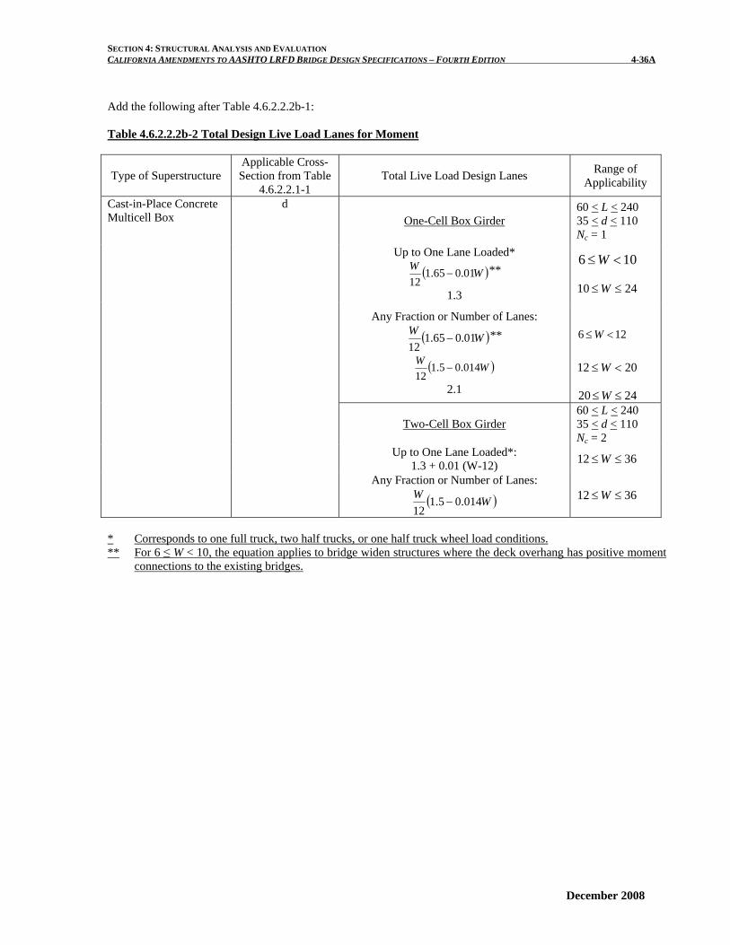
Add the following after Table 4.6.2.2.2b-1: Table 4.6.2.2.2b-2 Total Design Live Load Lanes for Moment
Type of Superstructure Applicable Cross-Section from Table
4.6.2.2.1-1
Total Live Load Design Lanes Range of
Applicability
One-Cell Box Girder 60 < L < 240 35 < d < 110 Nc = 1
Up to One Lane Loaded*
( )WW 01.065.112
− **
1.3
106 <≤W
2410 ≤≤W
Any Fraction or Number of Lanes:
( )WW 01.065.112
− **
( )WW 014.05.112
−
2.1
126 <≤W
2012 <≤W
2420 ≤≤W
Two-Cell Box Girder 60 < L < 240 35 < d < 110 Nc = 2
Up to One Lane Loaded*: 1.3 + 0.01 (W-12) 3612 ≤≤W
Cast-in-Place Concrete Multicell Box
d
Any Fraction or Number of Lanes:
( )WW 014.05.112
− 3612 ≤≤W
* Corresponds to one full truck, two half trucks, or one half truck wheel load conditions. ** For 6 ≤ W < 10, the equation applies to bridge widen structures where the deck overhang has positive moment
connections to the existing bridges.
December 2008

SECTION 4: STRUCTURAL ANALYSIS AND EVALUATION CALIFORNIA AMENDMENTS TO AASHTO LRFD BRIDGE DESIGN SPECIFICATIONS – FOURTH EDITION 4-36B_
December 2008
This page is intentionally left blank.

SECTION 4: STRUCTURAL ANALYSIS AND EVALUATION CALIFORNIA AMENDMENTS TO AASHTO LRFD BRIDGE DESIGN SPECIFICATIONS – FOURTH EDITION 4-38A
December 2008
4.6.2.2.2e Skewed Bridges
Delete the 1st Paragraph as follows:
When the line supports are skewed and the difference between skew angles of two adjacent lines of supports does not exceed 10o, the bending moment in the beams may be reduced in accordance with Table 1.
C4.6.2.2.2e
Revise the 1st Paragraph as follows:
Accepted reduction factors are not currently available for cases not covered in Table 1. Caltrans presently does not take advantage of the reduction in load distribution factors for moment in longitudinal beams on skewed supports.

SECTION 4: STRUCTURAL ANALYSIS AND EVALUATION CALIFORNIA AMENDMENTS TO AASHTO LRFD BRIDGE DESIGN SPECIFICATIONS – FOURTH EDITION 4-38B
December 2008
This page is intentionally left blank.
SECTION 4: STRUCTURAL ANALYSIS AND EVALUATION CALIFORNIA AMENDMENTS TO AASHTO LRFD BRIDGE DESIGN SPECIFICATIONS – FOURTH EDITION 4-40A
December 2008
4.6.2.2.3 Distribution Factor Method for Shear
Revise the following:
4.6.2.2.3a-i Interior Beams
C4.6.2.2.3
Add the following: The distribution factor method for girder shear
should be used when the superstructure in the mathematical model is analyzed as a spine beam in 1-D, 2-D, or 3-D space.
Add the following: 4.6.2.2.3a-ii Monolithic One- and Two-Cell Boxes For cast-in-place concrete box girder shown as
cross-section type “d”, the live load distribution for shear in one-cell and two-cell (Nc = 1 & 2) boxes shall be specified in terms of whole-width analysis. Such cross-sections shall be designed for the total live load lanes specified in Table 2 where the shear reinforcement shall be equally distributed to each girder web (for non-skew conditions).
C4.6.2.2.3a-ii
Add the following:
The Caltrans Structural Analysis Committee conducted parametric studies on one-cell and two-cell box girder bridges using SAP2000 3D analysis. The equations for the total live load lanes are applicable to box girders that meet the following conditions:
• Equal girder spacing, • 060≤
d .12
04.0 ≤L
• Deck overhang length < 0.5S
The distribution factor method may be used when the superstructure in the mathematical model is analyzed as a spine beam in 1-D, 2-D, or 3-D space.

SECTION 4: STRUCTURAL ANALYSIS AND EVALUATION CALIFORNIA AMENDMENTS TO AASHTO LRFD BRIDGE DESIGN SPECIFICATIONS – FOURTH EDITION 4-40B
This page is intentionally left blank.
December 2008
SECTION 4: STRUCTURAL ANALYSIS AND EVALUATION CALIFORNIA AMENDMENTS TO AASHTO LRFD BRIDGE DESIGN SPECIFICATIONS – FOURTH EDITION 4-41A
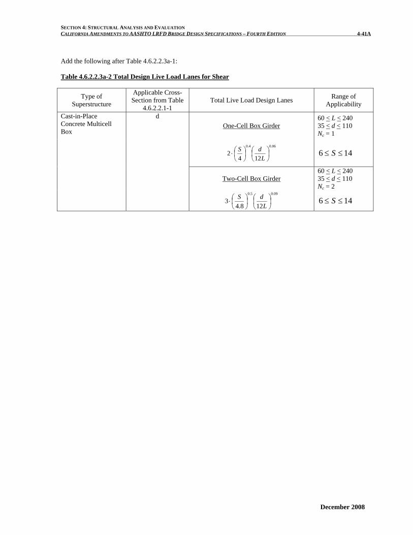
Add the following after Table 4.6.2.2.3a-1: Table 4.6.2.2.3a-2 Total Design Live Load Lanes for Shear
Type of Superstructure
Applicable Cross-Section from Table
4.6.2.2.1-1 Total Live Load Design Lanes Range of
Applicability
d One-Cell Box Girder
60 < L < 240 35 < d < 110 Nc = 1
06.04.0
1242 ⎟
⎠⎞
⎜⎝⎛
⎟⎠⎞
⎜⎝⎛⋅
LdS 146 ≤≤ S
Two-Cell Box Girder
60 < L < 240 35 < d < 110 Nc = 2
Cast-in-Place Concrete Multicell Box
09.05.0
128.43 ⎟
⎠⎞
⎜⎝⎛
⎟⎠⎞
⎜⎝⎛⋅
LdS 146 ≤≤ S
December 2008

SECTION 4: STRUCTURAL ANALYSIS AND EVALUATION CALIFORNIA AMENDMENTS TO AASHTO LRFD BRIDGE DESIGN SPECIFICATIONS – FOURTH EDITION 4-41B
This page is intentionally left blank.
December 2008
SECTION 4: STRUCTURAL ANALYSIS AND EVALUATION CALIFORNIA AMENDMENTS TO AASHTO LRFD BRIDGE DESIGN SPECIFICATIONS – FOURTH EDITION 4-44A
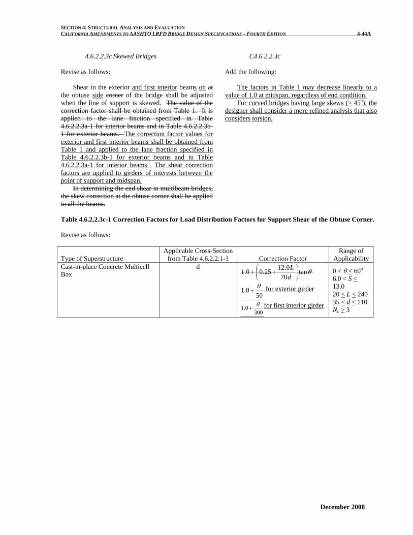
4.6.2.2.3c Skewed Bridges Revise as follows:
Shear in the exterior and first interior beams on at
the obtuse side corner of the bridge shall be adjusted when the line of support is skewed. The value of the correction factor shall be obtained from Table 1. It is applied to the lane fraction specified in Table 4.6.2.2.3a-1 for interior beams and in Table 4.6.2.2.3b-1 for exterior beams. The correction factor values for exterior and first interior beams shall be obtained from Table 1 and applied to the lane fraction specified in Table 4.6.2.2.3b-1 for exterior beams and in Table 4.6.2.2.3a-1 for interior beams. The shear correction factors are applied to girders of interests between the point of support and midspan.
In determining the end shear in multibeam bridges, the skew correction at the obtuse corner shall be applied to all the beams.
C4.6.2.2.3c Add the following:
The factors in Table 1 may decrease linearly to a value of 1.0 at midspan, regardless of end condition.
For curved bridges having large skews (> 45o), the designer shall consider a more refined analysis that also considers torsion.
Table 4.6.2.2.3c-1 Correction Factors for Load Distribution Factors for Support Shear of the Obtuse Corner. Revise as follows:
Type of Superstructure Applicable Cross-Section
from Table 4.6.2.2.1-1
Correction Factor Range of
Applicability Cast-in-place Concrete Multicell Box
d θtan
700.1225.00.1 ⎟
⎠⎞
⎜⎝⎛ ++
dL
500.1 θ+ for exterior girder
3000.1 θ+ for first interior girder
0 < θ < 60o
6.0 < S < 13.0 20 < L < 240 35 < d < 110 Nc > 3
December 2008

SECTION 4: STRUCTURAL ANALYSIS AND EVALUATION CALIFORNIA AMENDMENTS TO AASHTO LRFD BRIDGE DESIGN SPECIFICATIONS – FOURTH EDITION 4-44B_
December 2008
This page is intentionally left blank.
SECTION 4: STRUCTURAL ANALYSIS AND EVALUATION CALIFORNIA AMENDMENTS TO AASHTO LRFD BRIDGE DESIGN SPECIFICATIONS – FOURTH EDITION 4-46A_
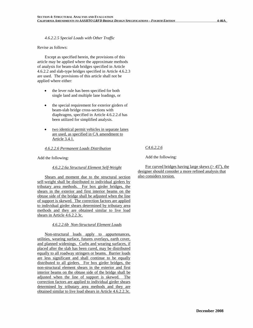
4.6.2.2.5 Special Loads with Other Traffic Revise as follows:
Except as specified herein, the provisions of this article may be applied where the approximate methods of analysis for beam-slab bridges specified in Article 4.6.2.2 and slab-type bridges specified in Article 4.6.2.3 are used. The provisions of this article shall not be applied where either:
• the lever rule has been specified for both
single land and multiple lane loadings, or • the special requirement for exterior girders of
beam-slab bridge cross-sections with diaphragms, specified in Article 4.6.2.2.d has been utilized for simplified analysis.
• two identical permit vehicles in separate lanes
are used, as specified in CA amendment to Article 3.4.1.
4.6.2.2.6 Permanent Loads Distribution
Add the following:
4.6.2.2.6a Structural Element Self-Weight
Shears and moment due to the structural section
self-weight shall be distributed to individual girders by tributary area methods. For box girder bridges, the shears in the exterior and first interior beams on the obtuse side of the bridge shall be adjusted when the line of support is skewed. The correction factors are applied to individual girder shears determined by tributary area methods and they are obtained similar to live load shears in Article 4.6.2.2.3c.
4.6.2.2.6b Non-Structural Element Loads
Non-structural loads apply to appurtenances, utilities, wearing surface, futures overlays, earth cover, and planned widenings. Curbs and wearing surfaces, if placed after the slab has been cured, may be distributed equally to all roadway stringers or beams. Barrier loads are less significant and shall continue to be equally distributed to all girders. For box girder bridges, the non-structural element shears in the exterior and first interior beams on the obtuse side of the bridge shall be adjusted when the line of support is skewed. The correction factors are applied to individual girder shears determined by tributary area methods and they are obtained similar to live load shears in Article 4.6.2.2.3c.
C4.6.2.2.6 Add the following:
For curved bridges having large skews (> 45o), the
designer should consider a more refined analysis that also considers torsion.
December 2008

SECTION 4: STRUCTURAL ANALYSIS AND EVALUATION CALIFORNIA AMENDMENTS TO AASHTO LRFD BRIDGE DESIGN SPECIFICATIONS – FOURTH EDITION 4-46B_
This page is intentionally left blank.
December 2008
SECTION 4: STRUCTURAL ANALYSIS AND EVALUATION CALIFORNIA AMENDMENTS TO AASHTO LRFD BRIDGE DESIGN SPECIFICATIONS – FOURTH EDITION 4-48A
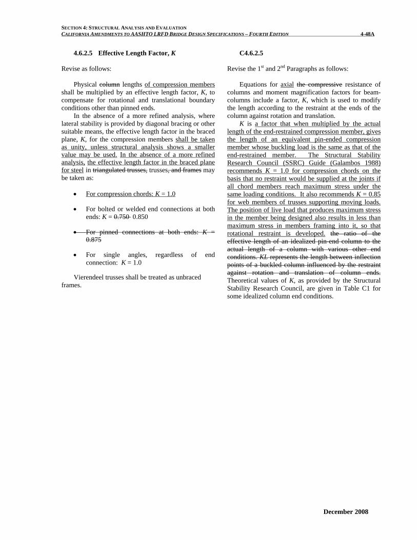
4.6.2.5 Effective Length Factor, K Revise as follows:
Physical column lengths of compression members shall be multiplied by an effective length factor, K, to compensate for rotational and translational boundary conditions other than pinned ends.
In the absence of a more refined analysis, where lateral stability is provided by diagonal bracing or other suitable means, the effective length factor in the braced plane, K, for the compression members shall be taken as unity, unless structural analysis shows a smaller value may be used. In the absence of a more refined analysis, the effective length factor in the braced plane for steel in triangulated trusses, trusses, and frames may be taken as:
• For compression chords: K = 1.0
• For bolted or welded end connections at both ends: K = 0.750 0.850
• For pinned connections at both ends: K = 0.875
• For single angles, regardless of end connection: K = 1.0
Vierendeel trusses shall be treated as unbraced frames.
C4.6.2.5 Revise the 1st and 2nd Paragraphs as follows:
Equations for axial the compressive resistance of columns and moment magnification factors for beam-columns include a factor, K, which is used to modify the length according to the restraint at the ends of the column against rotation and translation.
K is a factor that when multiplied by the actual length of the end-restrained compression member, gives the length of an equivalent pin-ended compression member whose buckling load is the same as that of the end-restrained member. The Structural Stability Research Council (SSRC) Guide (Galambos 1988) recommends K = 1.0 for compression chords on the basis that no restraint would be supplied at the joints if all chord members reach maximum stress under the same loading conditions. It also recommends K = 0.85 for web members of trusses supporting moving loads. The position of live load that produces maximum stress in the member being designed also results in less than maximum stress in members framing into it, so that rotational restraint is developed. the ratio of the effective length of an idealized pin-end column to the actual length of a column with various other end conditions. KL represents the length between inflection points of a buckled column influenced by the restraint against rotation and translation of column ends. Theoretical values of K, as provided by the Structural Stability Research Council, are given in Table C1 for some idealized column end conditions.
December 2008

SECTION 4: STRUCTURAL ANALYSIS AND EVALUATION CALIFORNIA AMENDMENTS TO AASHTO LRFD BRIDGE DESIGN SPECIFICATIONS – FOURTH EDITION 4-48B
This page is intentionally left blank.
December 2008
SECTION 4: STRUCTURAL ANALYSIS AND EVALUATION CALIFORNIA AMENDMENTS TO AASHTO LRFD BRIDGE DESIGN SPECIFICATIONS – FOURTH EDITION 4-52A
December 2008
4.6.2.6 Effective Flange Width 4.6.2.6.1 General
Revise as follows:
In the absence of a more refined analysis and/or unless otherwise specified, limits of the width of a concrete slab, taken as effective in composite action for determining resistance for all limit states, shall be as specified herein. The calculation of deflections should be based on the full flange width. For the calculation of live load deflections, where required, the provisions of Article 2.5.2.6.2 shall apply.
The effective span length used in calculating effective flange width may be taken as the actual span for simply supported spans and the distance between points of permanent load inflection for continuous spans, as appropriate for either positive or negative moments.
The effective flange width may be taken as:
If S/L ≤ 0.32, then:
bbeff = (4.6.2.6.1-1)
Otherwise:
mineff bbLS..b ≥⎥
⎦
⎤⎢⎣
⎡⎟⎠⎞
⎜⎝⎛−= 740241 (4.6.2.6.1-2)
where b = full flange width (ft) beff = effective flange width (ft) bmin = minimum effective flange width (ft) L = span length (ft) S = girder spacing (ft)
Equations 1 and 2 shall be used within the limit of
skew angle θ ≤ 60o. For θ > 60o, unless a more refined analysis is performed, the effective flange width may be taken as bmin and shall not exceed the girder spacing.
C4.6.2.6.1
Revise as follows:
Longitudinal stresses in the flanges are spread across the flange and the composite deck slab by in-plane shear stresses. Therefore, the longitudinal stresses are not uniform. The effective flange width is a reduced the width over which the longitudinal stresses are assumed to be uniformly distributed and yet result in the same force as the nonuniform stress distribution would if integrated over the whole width.
The effective flange width provisions are based on
state-of-the-art research by Chen, et al. (2005), Nassif et al. (2005), and Caltrans revisions. The concrete deck slabs shall be designed in accordance with Article 9.7.
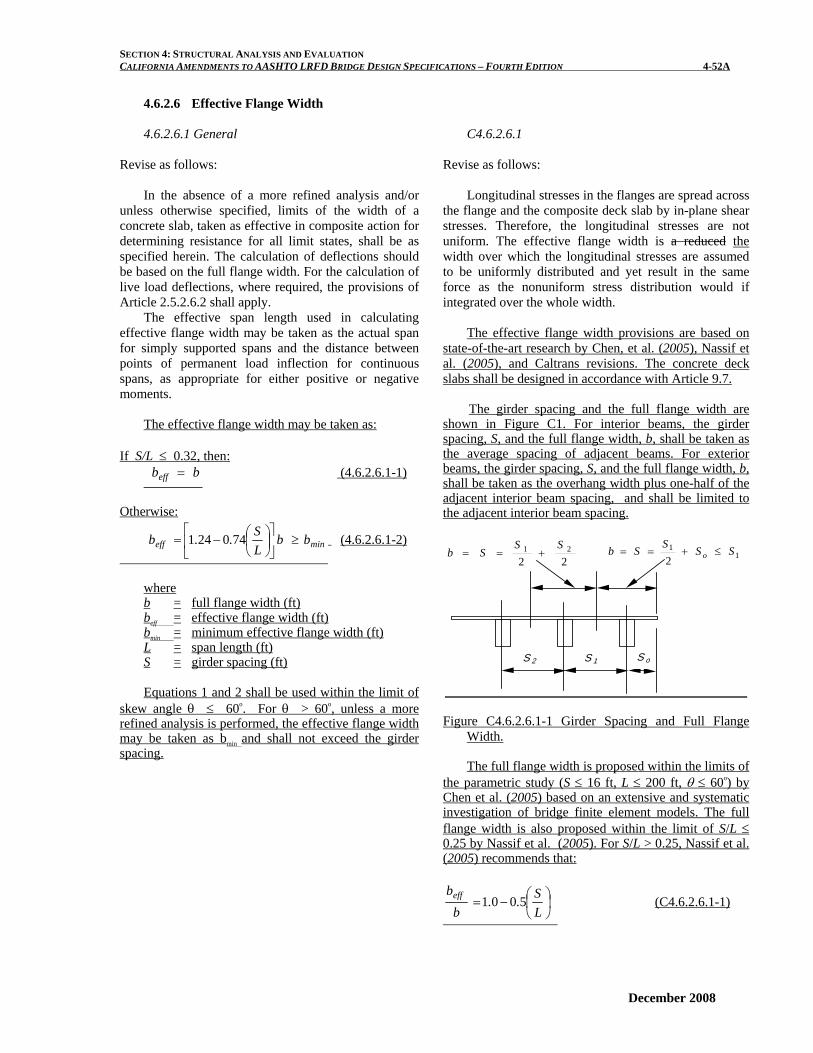
The girder spacing and the full flange width are
shown in Figure C1. For interior beams, the girder spacing, S, and the full flange width, b, shall be taken as the average spacing of adjacent beams. For exterior beams, the girder spacing, S, and the full flange width, b, shall be taken as the overhang width plus one-half of the adjacent interior beam spacing, and shall be limited to the adjacent interior beam spacing.
S 1S 2 S o
2221 SS
Sb +== 11
2SSSSb o ≤+==
Figure C4.6.2.6.1-1 Girder Spacing and Full Flange Width.
The full flange width is proposed within the limits of
the parametric study (S ≤ 16 ft, L ≤ 200 ft, θ ≤ 60o) by Chen et al. (2005) based on an extensive and systematic investigation of bridge finite element models. The full flange width is also proposed within the limit of S/L ≤ 0.25 by Nassif et al. (2005). For S/L > 0.25, Nassif et al. (2005) recommends that:
⎟⎠⎞
⎜⎝⎛−=
LS..
bbeff 5001 (C4.6.2.6.1-1)
SECTION 4: STRUCTURAL ANALYSIS AND EVALUATION CALIFORNIA AMENDMENTS TO AASHTO LRFD BRIDGE DESIGN SPECIFICATIONS – FOURTH EDITION 4-52B For interior beams, the minimum effective flange width, bmin effective flange width may be taken as the least of:
• One-quarter of the effective span length; • 12.0 times the average depth of the slab, plus the
greater of web thickness or one-half the width of the top flange of the girder. ; or
• The average spacing of adjacent beams.
For exterior beams, the minimum effective flange width, bmin effective flange width may be taken as one-half the effective width of the adjacent interior beam, plus the least of: • One-eighth of the effective span length; • 6.0 times the average depth of the slab, plus the
greater of one-half the web thickness or one-quarter of the width of the top flange of the basic girder.; or
• The width of the overhang.
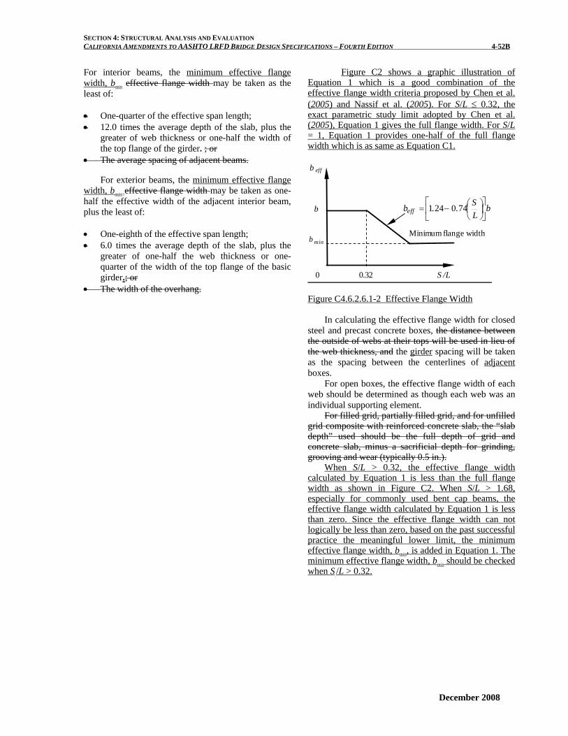
Figure C2 shows a graphic illustration of Equation 1 which is a good combination of the effective flange width criteria proposed by Chen et al. (2005) and Nassif et al. (2005). For S/L ≤ 0.32, the exact parametric study limit adopted by Chen et al. (2005), Equation 1 gives the full flange width. For S/L = 1, Equation 1 provides one-half of the full flange width which is as same as Equation C1.
b eff
b
b min
0.32 S /L
bLS..beff ⎥
⎦
⎤⎢⎣
⎡⎟⎠⎞
⎜⎝⎛−= 740241
Minimum flange width
0 Figure C4.6.2.6.1-2 Effective Flange Width
In calculating the effective flange width for closed steel and precast concrete boxes, the distance between the outside of webs at their tops will be used in lieu of the web thickness, and the girder spacing will be taken as the spacing between the centerlines of adjacent boxes.
For open boxes, the effective flange width of each web should be determined as though each web was an individual supporting element.
For filled grid, partially filled grid, and for unfilled grid composite with reinforced concrete slab, the “slab depth” used should be the full depth of grid and concrete slab, minus a sacrificial depth for grinding, grooving and wear (typically 0.5 in.).
When S/L > 0.32, the effective flange width calculated by Equation 1 is less than the full flange width as shown in Figure C2. When S/L > 1.68, especially for commonly used bent cap beams, the effective flange width calculated by Equation 1 is less than zero. Since the effective flange width can not logically be less than zero, based on the past successful practice the meaningful lower limit, the minimum effective flange width, bmin, is added in Equation 1. The minimum effective flange width, bmin should be checked when S /L > 0.32.
December 2008
SECTION 4: STRUCTURAL ANALYSIS AND EVALUATION CALIFORNIA AMENDMENTS TO AASHTO LRFD BRIDGE DESIGN SPECIFICATIONS – FOURTH EDITION 4-52C
For negative moment region only, one possible alternative for determining the effective flange width is provided by Equation C2:
01001000309480 ..SL..
bbeff ≤θ−⎟
⎠⎞
⎜⎝⎛+= (C4.6.2.6.1-2)
where L = span length (ft), the lesser of the two span lengths
if the two span lengths differ θ = skew angle (o)
By comparing the results using the effective flange
width obtained from the finite element analyses and a full slab width, the difference can be as high as 8.5%. By using Equation C2 the difference can be reduced to approximately 5.9% in the worst case investigated by Chen et al. (2005).
Both the full physical flange width provision and Equation C2 were formulated based on finite element models that developed slab cracking in the negative moment sections under service loads. Thus, in negative moment regions these provisions should be used assuming the slab to be cracked, i.e., the composite section to consist of the beam section and the longitudinal reinforcement within the effective width of concrete deck.
A more refined analysis should be performed to determine the effective flange width when θ > 60o.
Where a structurally continuous concrete barrier is present and is included in the models used for analysis as permitted in Article 4.5.1, the width of overhang for the purpose of this Article may be extended by:
s
b
tA
w2
=Δ (C4.6.2.6.1-1)
where: Ab = cross-sectional area of the barrier (in.2) ts = depth of deck slab (in.)
For integral bent caps, the effective flange width
overhanging each side of the bent cap web shall not exceed six times the least slab thickness, or 1/10 the span length of the bent cap. For cantilevered bent caps, the span length shall be taken as two times the length of the cantilever span.
The provisions for the effective flange width for
the integral bent cap are based on past successful practice, specified by Article 8.10.1.4 of the 2002 AASHTO Standard Specifications.
December 2008

SECTION 4: STRUCTURAL ANALYSIS AND EVALUATION CALIFORNIA AMENDMENTS TO AASHTO LRFD BRIDGE DESIGN SPECIFICATIONS – FOURTH EDITION 4-52D
This page is intentionally left blank.
December 2008

SECTION 4: STRUCTURAL ANALYSIS AND EVALUATION CALIFORNIA AMENDMENTS TO AASHTO LRFD BRIDGE DESIGN SPECIFICATIONS – FOURTH EDITION 4-66A
December 2008
4.6.3.1 General
Revise the 2nd Paragraph as follows:
A structurally continuous railing, barrier, or median, acting compositely with the supporting components, may be consider to be structurally active at service and fatigue limit states. Railings, barriers, and medians shall not be considered as structurally continuous, except as allowed for deck overhang load distribution in Article 3.6.1.3.4
C4.6.3.1
Revise the 2nd paragraph as follows:
This provision reflects the experimentally observed response of bridges. This source of stiffness has traditionally been neglected but exists and may be included, per the limits of Article 3.6.1.3.4, provided that full composite behavior is assured.

SECTION 4: STRUCTURAL ANALYSIS AND EVALUATION CALIFORNIA AMENDMENTS TO AASHTO LRFD BRIDGE DESIGN SPECIFICATIONS – FOURTH EDITION 4-66B
This page is intentionally left blank.
December 2008

SECTION 4: STRUCTURAL ANALYSIS AND EVALUATION CALIFORNIA AMENDMENTS TO AASHTO LRFD BRIDGE DESIGN SPECIFICATIONS – FOURTH EDITION 4-67A
4.6.3.2.1 General Revise the 1st Paragraph as follows:
Unless otherwise specified, flexural and torsional deformation of the deck shall be considered in the analysis but vertical shear deformation may be neglected. Yield-line analysis shall not be used.
December 2008

SECTION 4: STRUCTURAL ANALYSIS AND EVALUATION CALIFORNIA AMENDMENTS TO AASHTO LRFD BRIDGE DESIGN SPECIFICATIONS – FOURTH EDITION 4-67B
This page is intentionally left blank.
December 2008

SECTION 4: STRUCTURAL ANALYSIS AND EVALUATION CALIFORNIA AMENDMENTS TO AASHTO LRFD BRIDGE DESIGN SPECIFICATIONS – FOURTH EDITION 4-86A
Add References Chung, P.C., Shen, Bin, Bikaee. S., Schendel, R., Logus, A., “Live Load Distribution in One and Two-Cell Box-Girder Bridges- Draft,” Report No. CT-SAC-01, California Department of Transportation, November 2008. State of California, Department of Transportation, Standard Plans May 2006
December 2008

SECTION 4: STRUCTURAL ANALYSIS AND EVALUATION CALIFORNIA AMENDMENTS TO AASHTO LRFD BRIDGE DESIGN SPECIFICATIONS – FOURTH EDITION 4-86B
This page is intentionally left blank.
December 2008

![LoadEvaluationandStructuralLoad Evaluation and Structural ...mvdpanel.net/adjuntosTextos/cz47hroew7iqkp/699/korea.pdf0 10 203040 5060 0 Displacement [mm] Section Up-outboard Section](https://img.pdfslide.net/doc/110x75/5fead74be7cb7d437e298095/loadevaluationandstructuralload-evaluation-and-structural-0-10-203040-5060-0.jpg)