Embed Size (px)
Citation preview
Design and Build of Passenger Terminal Building North Extension At Macau International Airport (RFQ-198)
Section 7 –
Drawings, conceptual design and Design Requirement Brief
(Revision 1)
Design and Build of Passenger Terminal Building North Extension At Macau International Airport
S.7/1
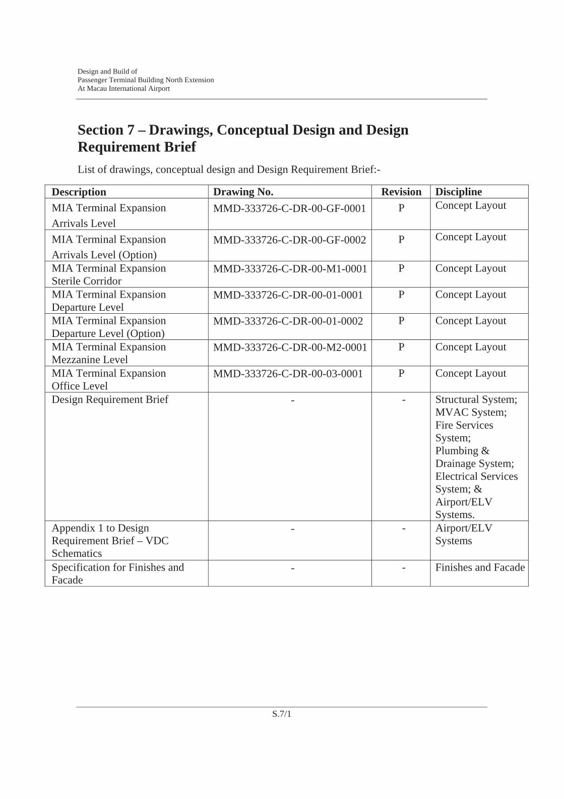
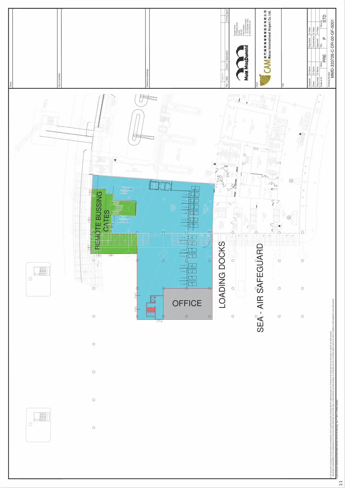
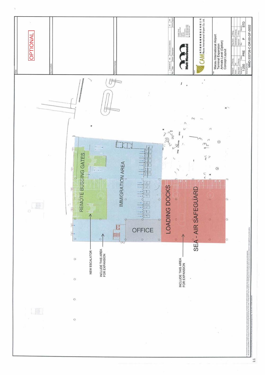
Section 7 – Drawings, Conceptual Design and Design Requirement BriefList of drawings, conceptual design and Design Requirement Brief:-
Description Drawing No. Revision DisciplineMIA Terminal Expansion Arrivals Level
MMD-333726-C-DR-00-GF-0001 P Concept Layout
MIA Terminal Expansion Arrivals Level (Option)
MMD-333726-C-DR-00-GF-0002 P Concept Layout
MIA Terminal Expansion Sterile Corridor
MMD-333726-C-DR-00-M1-0001 P Concept Layout
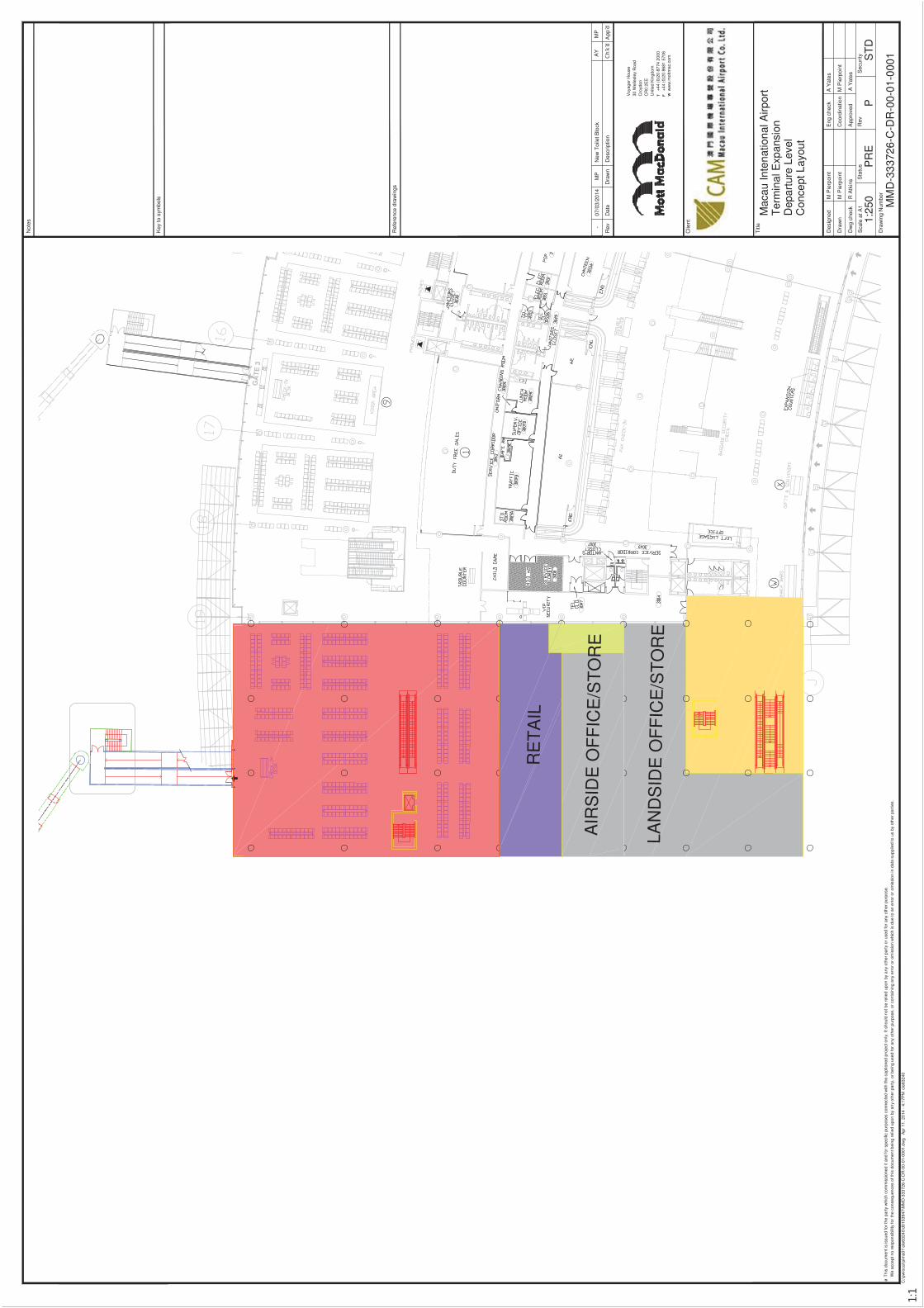
MIA Terminal Expansion Departure Level
MMD-333726-C-DR-00-01-0001 P Concept Layout
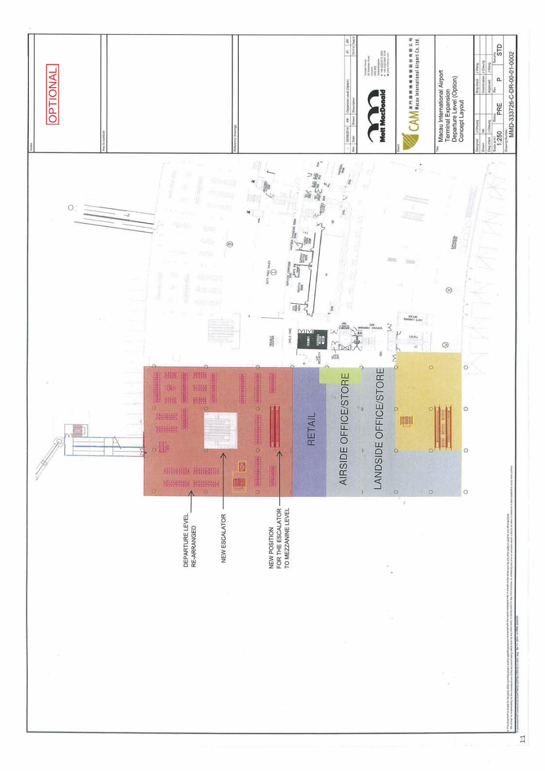
MIA Terminal Expansion Departure Level (Option)
MMD-333726-C-DR-00-01-0002 P Concept Layout
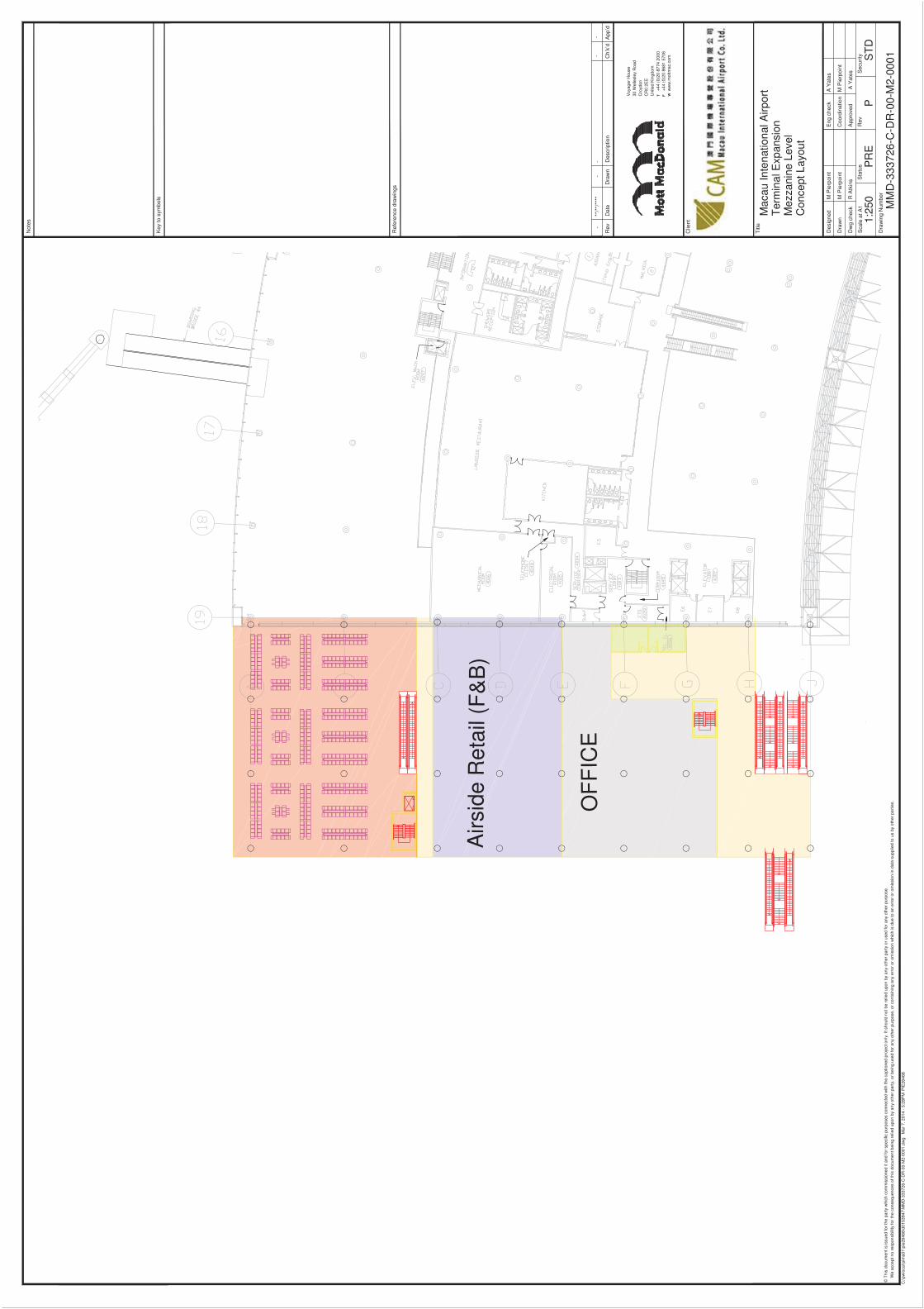
MIA Terminal Expansion Mezzanine Level
MMD-333726-C-DR-00-M2-0001 P Concept Layout
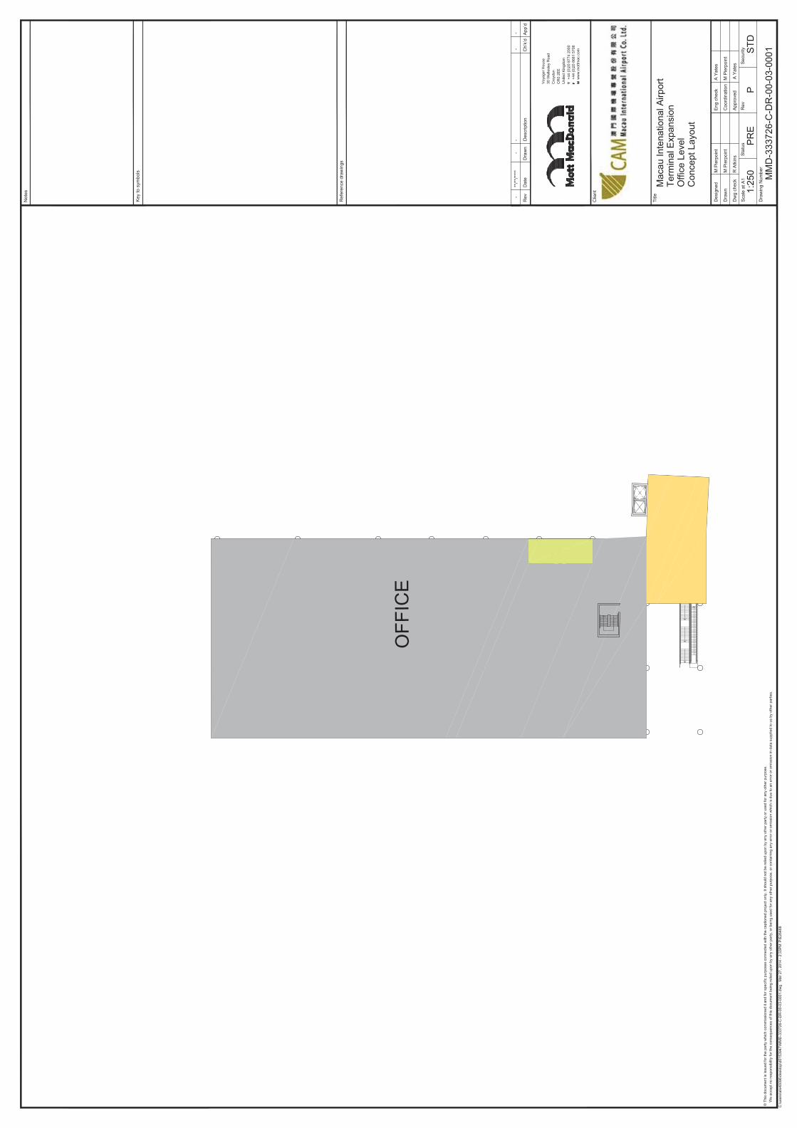
MIA Terminal Expansion Office Level
MMD-333726-C-DR-00-03-0001 P Concept Layout
Design Requirement Brief - - Structural System; MVAC System; Fire Services System; Plumbing & Drainage System; Electrical Services System; & Airport/ELV Systems.
Appendix 1 to Design Requirement Brief – VDC Schematics
- - Airport/ELV Systems
Specification for Finishes and Facade
- - Finishes and Facade
OFFICE LOA
DIN
G D
OC
KS
SE
A -
AIR
SA
FE
GU
AR
DRE
MO
TE
BU
SS
ING
GA
TE
S
Key
to s
ymbo
ls
Des
crip
tion
Dra
wn
Dat
eR
ev
Rev
Sta
tus
Dra
win
g N
umbe
r
Sca
le a
t A1
Eng
che
ck
App
rove
d
Coo
rdin
atio
n
Dw
g ch
eck
Dra
wn
Des
igne
d
Titl
e
Not
es
Clie
nt
Ref
eren
ce d
raw
ings
Sec
urity
C:\p
wlo
cal\p
ims0
1\cl
e632
40\d
0153
947\
MM
D-3
3372
6-C
-DR
-00-
XX
-000
4.dw
g A
pr 1
1, 2
014
- 4:
18P
M c
le63
240
T F W
E C
lerc
h
E C
lerc
h
R A
tkin
s
A Y
ates
A Y
ates
A Y
ates
PR
E
MM
D-3
3372
6-C
-DR
-00-
GF
-000
1
PS
TD
Voy
ager
Hou
se30
Wel
lesl
ey R
oad
Cro
ydon
CR
0 2E
EU
nite
d K
ingd
om+
44 (
0)20
877
4 20
00+
44 (
0)20
868
1 57
06w
ww
.mot
tmac
.com
Thi
s do
cum
ent i
s is
sued
for
the
part
y w
hich
com
mis
sion
ed it
and
for
spec
ific
purp
oses
con
nect
ed w
ith th
e ca
ptio
ned
proj
ect o
nly.
It s
houl
d no
t be
relie
d up
on b
y an
y ot
her
part
y or
use
d fo
r an
y ot
her
purp
ose.
We
acce
pt n
o re
spon
sibi
lity
for
the
cons
eque
nces
of t
his
docu
men
t bei
ng r
elie
d up
on b
y an
y ot
her
part
y, o
r be
ing
used
for
any
othe
r pu
rpos
e, o
r co
ntai
ning
any
err
or o
r om
issi
on w
hich
is d
ue to
an
erro
r or
om
issi
on in
dat
a su
pplie
d to
us
by o
ther
par
ties.
-**
/**/
****
--
--
OP
TIO
NA
L
Key
to s
ymbo
ls
Des
crip
tion
Dra
wn
Dat
eR
ev
Rev
Sta
tus
Dra
win
g N
umbe
r
Sca
le a
t A1
Eng
che
ck
App
rove
d
Coo
rdin
atio
n
Dw
g ch
eck
Dra
wn
Des
igne
d
Titl
e
Not
es
Clie
nt
Ref
eren
ce d
raw
ings
Sec
urity
C:\p
wlo
cal\p
ims0
1\cl
e632
40\d
0153
947\
MM
D-3
3372
6-C
-DR
-00-
M1-
0001
.dw
g A
pr 1
1, 2
014
- 4:
17P
M c
le63
240
T F W
Mac
au In
tena
tiona
l Airp
ort
Ter
min
al E
xpan
sion
Ser
ile C
orrid
orC
once
pt L
ayou
t
M P
ierp
oint
M P
ierp
oint
R A
tkin
s
A Y
ates
M P
ierp
oint
A Y
ates
1:25
0P
RE
MM
D-3
3372
6-C
-DR
-00-
M1-
0001
PS
TD
Voy
ager
Hou
se30
Wel
lesl
ey R
oad
Cro
ydon
CR
0 2E
EU
nite
d K
ingd
om+
44 (
0)20
877
4 20
00+
44 (
0)20
868
1 57
06w
ww
.mot
tmac
.com
Thi
s do
cum
ent i
s is
sued
for
the
part
y w
hich
com
mis
sion
ed it
and
for
spec
ific
purp
oses
con
nect
ed w
ith th
e ca
ptio
ned
proj
ect o
nly.
It s
houl
d no
t be
relie
d up
on b
y an
y ot
her
part
y or
use
d fo
r an
y ot
her
purp
ose.
We
acce
pt n
o re
spon
sibi
lity
for
the
cons
eque
nces
of t
his
docu
men
t bei
ng r
elie
d up
on b
y an
y ot
her
part
y, o
r be
ing
used
for
any
othe
r pu
rpos
e, o
r co
ntai
ning
any
err
or o
r om
issi
on w
hich
is d
ue to
an
erro
r or
om
issi
on in
dat
a su
pplie
d to
us
by o
ther
par
ties.
-**
/**/
****
--
--
RE
TA
IL
LAN
DS
IDE
OF
FIC
E/S
TO
RE
AIR
SID
E O
FF
ICE
/ST
OR
E
Key
to s
ymbo
ls
Des
crip
tion
Dra
wn
Dat
eR
ev
Rev
Sta
tus
Dra
win
g N
umbe
r
Sca
le a
t A1
Eng
che
ck
App
rove
d
Coo
rdin
atio
n
Dw
g ch
eck
Dra
wn
Des
igne
d
Titl
e
Not
es
Clie
nt
Ref
eren
ce d
raw
ings
Sec
urity
C:\p
wlo
cal\p
ims0
1\cl
e632
40\d
0153
947\
MM
D-3
3372
6-C
-DR
-00-
01-0
001.
dwg
Apr
11,
201
4 -
4:17
PM
cle
6324
0
T F W
Mac
au In
tena
tiona
l Airp
ort
Ter
min
al E
xpan
sion
Dep
artu
re L
evel
Con
cept
Lay
out
M P
ierp
oint
M P
ierp
oint
R A
tkin
s
A Y
ates
M P
ierp
oint
A Y
ates
1:25
0P
RE
MM
D-3
3372
6-C
-DR
-00-
01-0
001
PS
TD
Voy
ager
Hou
se30
Wel
lesl
ey R
oad
Cro
ydon
CR
0 2E
EU
nite
d K
ingd
om+
44 (
0)20
877
4 20
00+
44 (
0)20
868
1 57
06w
ww
.mot
tmac
.com
Thi
s do
cum
ent i
s is
sued
for
the
part
y w
hich
com
mis
sion
ed it
and
for
spec
ific
purp
oses
con
nect
ed w
ith th
e ca
ptio
ned
proj
ect o
nly.
It s
houl
d no
t be
relie
d up
on b
y an
y ot
her
part
y or
use
d fo
r an
y ot
her
purp
ose.
We
acce
pt n
o re
spon
sibi
lity
for
the
cons
eque
nces
of t
his
docu
men
t bei
ng r
elie
d up
on b
y an
y ot
her
part
y, o
r be
ing
used
for
any
othe
r pu
rpos
e, o
r co
ntai
ning
any
err
or o
r om
issi
on w
hich
is d
ue to
an
erro
r or
om
issi
on in
dat
a su
pplie
d to
us
by o
ther
par
ties.
-07
/03/
2014
MP
New
Toi
let B
lock
AY
MP
OP
TIO
NA
L
OF
FIC
E
Airs
ide
Ret
ail (
F&
B)
Key
to s
ymbo
ls
Des
crip
tion
Dra
wn
Dat
eR
ev
Rev
Sta
tus
Dra
win
g N
umbe
r
Sca
le a
t A1
Eng
che
ck
App
rove
d
Coo
rdin
atio
n
Dw
g ch
eck
Dra
wn
Des
igne
d
Titl
e
Not
es
Clie
nt
Ref
eren
ce d
raw
ings
Sec
urity
C:\p
wlo
cal\p
ims0
1\pi
e264
68\d
0153
947\
MM
D-3
3372
6-C
-DR
-00-
M2-
0001
.dw
g M
ar 7
, 201
4 -
5:28
PM
PIE
2646
8
T F W
Mac
au In
tena
tiona
l Airp
ort
Ter
min
al E
xpan
sion
Mez
zani
ne L
evel
Con
cept
Lay
out
M P
ierp
oint
M P
ierp
oint
R A
tkin
s
A Y
ates
M P
ierp
oint
A Y
ates
1:25
0P
RE
MM
D-3
3372
6-C
-DR
-00-
M2-
0001
PS
TD
Voy
ager
Hou
se30
Wel
lesl
ey R
oad
Cro
ydon
CR
0 2E
EU
nite
d K
ingd
om+
44 (
0)20
877
4 20
00+
44 (
0)20
868
1 57
06w
ww
.mot
tmac
.com
Thi
s do
cum
ent i
s is
sued
for
the
part
y w
hich
com
mis
sion
ed it
and
for
spec
ific
purp
oses
con
nect
ed w
ith th
e ca
ptio
ned
proj
ect o
nly.
It s
houl
d no
t be
relie
d up
on b
y an
y ot
her
part
y or
use
d fo
r an
y ot
her
purp
ose.
We
acce
pt n
o re
spon
sibi
lity
for
the
cons
eque
nces
of t
his
docu
men
t bei
ng r
elie
d up
on b
y an
y ot
her
part
y, o
r be
ing
used
for
any
othe
r pu
rpos
e, o
r co
ntai
ning
any
err
or o
r om
issi
on w
hich
is d
ue to
an
erro
r or
om
issi
on in
dat
a su
pplie
d to
us
by o
ther
par
ties.
-**
/**/
****
--
--
“Design and Build”
of
Passenger Terminal Building North Extension
at
Macau International Airport
Phase 1
Design Requirement Brief
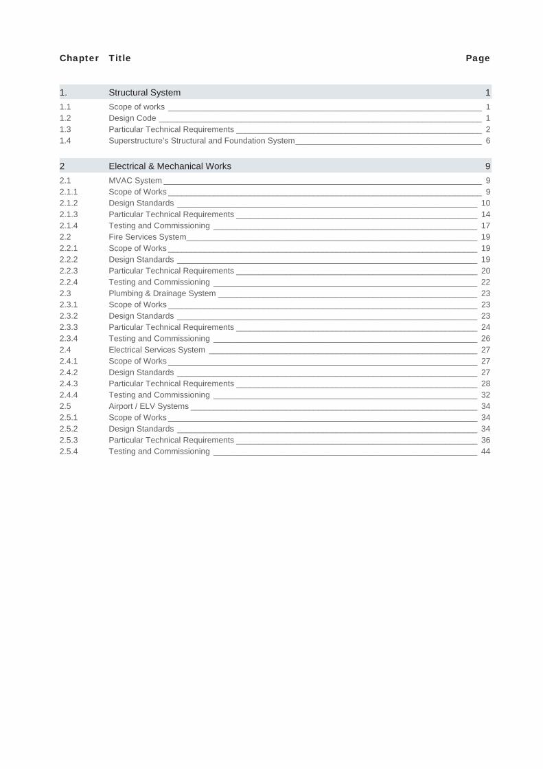
Chapter Title Page
1. Structural System 11.1 Scope of works _____________________________________________________________________ 11.2 Design Code _______________________________________________________________________ 11.3 Particular Technical Requirements ______________________________________________________ 21.4 Superstructure’s Structural and Foundation System _________________________________________ 6
2 Electrical & Mechanical Works 92.1 MVAC System ______________________________________________________________________ 92.1.1 Scope of Works _____________________________________________________________________ 92.1.2 Design Standards __________________________________________________________________ 102.1.3 Particular Technical Requirements _____________________________________________________ 142.1.4 Testing and Commissioning __________________________________________________________ 172.2 Fire Services System ________________________________________________________________ 192.2.1 Scope of Works ____________________________________________________________________ 192.2.2 Design Standards __________________________________________________________________ 192.2.3 Particular Technical Requirements _____________________________________________________ 202.2.4 Testing and Commissioning __________________________________________________________ 222.3 Plumbing & Drainage System _________________________________________________________ 232.3.1 Scope of Works ____________________________________________________________________ 232.3.2 Design Standards __________________________________________________________________ 232.3.3 Particular Technical Requirements _____________________________________________________ 242.3.4 Testing and Commissioning __________________________________________________________ 262.4 Electrical Services System ___________________________________________________________ 272.4.1 Scope of Works ____________________________________________________________________ 272.4.2 Design Standards __________________________________________________________________ 272.4.3 Particular Technical Requirements _____________________________________________________ 282.4.4 Testing and Commissioning __________________________________________________________ 322.5 Airport / ELV Systems _______________________________________________________________ 342.5.1 Scope of Works ____________________________________________________________________ 342.5.2 Design Standards __________________________________________________________________ 342.5.3 Particular Technical Requirements _____________________________________________________ 362.5.4 Testing and Commissioning __________________________________________________________ 44
1
1.1 Scope of works
The structural scope of works include the design and construction of the foundation (including pile caps) and the structural frame/shear walls for the expansion of the airport’s terminal building. The structural works shall include the demolition in part of the existing canopy to facilitate the construction of the expansion of the building.
1.2 Design Code
The local Macau standards should be followed and supplemented by Eurocode 2 & 3 and International Building Code.
56/96/M:
42/97/M:
32/97/M:
24/95/M:
47/96/M:
60/96/M:
64/96/M:
63/96/M:
GB50011-2001: -
29/2001/M
In addition, the following British Standards should be referenced:
- BS12: Specification of Portland Cement
- BS812: Testing aggregates
- BS882: Specification for aggregates from natural source for concrete
- BS1881 Testing concrete
- BS4466: Specification for scheduling, dimensioning, bending and cutting of steel
reinforcement for concrete.
- BS4483: Specification for steel fabric for the reinforcement of concrete
- BS8007: Code of Practice for design of concrete structures for retaining aqueous liquid
- Eurocode 2: Design of concrete structures
- Eurocode 3 : Design of steel structures
1. Structural System
2
- National Structural Steelwork S pecification (NSSS)
1.3 Particular Technical Requirements
The completed structure’s deflection and other structural movements should comply with the requirements of the designated codes of practices and the standards referenced therein.
Construction Materials: Cement
All cement shall be fresh Ordinary Portland cement shall comply with BS12 Part 2 1991. Other types of cement shall not be permitted without the written acceptance of the Engineer. The cement shall be produced by a manufacturer of good repute and subject to the endorsement of the Engineer. All cement to be used on the works shall be supplied from the same source unless alternate sources are endorsed by the by the engineer.
The contractor shall obtain a manufacturer’s certificate of test in accordance with the appropriate standards for each consignment of cement delivered to the site for use in the work. The Engineer may require that any cement, delivered to the site for use in the works to be sampled and tested in accordance with BS4550. Any batch of cement so tested which fails to comply with this specification will be rejected.
Construction Materials: Aggregates
Aggregates for concrete shall be from natural sources and shall comply with BS882 unless otherwise specified. In additional, the flakiness index when determined by the sieve method described in BS882 shall not exceed 35 for any sizes of aggregates. Aggregates finer than zone 4 of BS882 shall not be used. All aggregates shall be hard, durable, free from coatings of deleterious matter and shall be non porous. The grading of fine and coarse aggregates shall be to BS882:1992 and such as to produce a dense concrete of suitable workability with proportions of cement and water to be used.
The Engineer may require that any aggregate to be test for sulphate soundness in accordance with the latest edition of ASTM Test C289 before giving endorsement to any proposed source of supply. Notwithstanding any certificate of compliance or any prior endorsement given by the Engineer may, at any time, require that any aggregate deliver to the site, or else for use in the works, to be sampled and tested before it may be used. Any aggregate so tested which fails to comply with this specification may be rejected.
Construction Materials: Concrete
Structural concrete is specified in accordance with Macau Standard 60/96/M.
All concrete grade with prefix B denote designed mix. The reactive alkali of concrete expressed as the equivalent sodium oxide per cubic metre of concrete shall not exceed 3 kg. The concrete testing is to be undertaken in accordance with the requirements of the Macau Standards. The testing to be carried out include but not limited to compressive strength, flexural strength and early age compressive strength testing at 7 and 14 days.
The Contractor shall at his own expense provide all labour and materials including transportation to the testing laboratory, required to conduct concrete cube tests.
Concrete test cubes shall be made in 150mm cube steel moulds, filled in three 50mm layers, each layer being thoroughly compacted with a steel bar 380mm long having ramming surface of 25mm square and weighing 1.8kg for at least 35 strokes.
3
The cubes shall be suitably identified and recorded at the time of mould mix of concrete and location in the works from which the concrete has been taken for the cubes. A tank shall be provided by the Contractor for the purpose of curing test cubes to the satisfaction of the Engineer.
Should the test cubes fail to achieve the minimum resistance to crushing required for the concrete designed mix, the Engineer ay instruct the Contractors to carry out in-situ test at his own expenses to the Engineer’s satisfaction and/or reject the placed concrete. The Contractor shall also at his own expenses increase the proportion of cement in future mixes until such tests satisfy the concrete designed mix requirements.
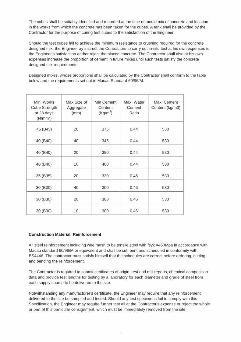
Designed mixes, whose proportions shall be calculated by the Contractor shall conform to the table below and the requirements set out in Macau Standard 60/96/M.
Min. Works Cube Strength
at 28 days (N/mm2)
Max Size of Aggregate
(mm)
Min Cement Content (Kg/m3)
Max. Water Cement
Ratio
Max. Cement Content (kg/m3)
45 (B45) 20 375 0.44 530
40 (B40) 40 345 0.44 530
40 (B40) 20 350 0.44 530
40 (B40) 10 400 0.44 530
35 (B35) 20 330 0.45 530
30 (B30) 40 300 0.46 530
30 (B30) 20 300 0.46 530
30 (B30) 10 300 0.46 530
Construction Material: Reinforcement
All steel reinforcement including wire mesh to be tensile steel with fsyk =460Mpa in accordance with Macau standard 60/96/M or equivalent and shall be cut, bent and scheduled in conformity with BS4446. The contractor must satisfy himself that the schedules are correct before ordering, cutting and bending the reinforcement.
The Contractor is required to submit certificates of origin, test and mill reports, chemical composition data and provide test lengths for testing by a laboratory for each diameter and grade of steel from each supply source to be delivered to the site.
Notwithstanding any manufacturer’s certificate, the Engineer may require that any reinforcement delivered to the site be sampled and tested. Should any test specimens fail to comply with this Specification, the Engineer may require further test all at the Contractor’s expense or reject the whole or part of this particular consignment, which must be immediately removed from the site.

4
All reinforcement shall be stored at least 150mm clear of the ground or floor, in clean conditions and in an orderly manner to the satisfaction of the Engineer.
All reinforcement shall, at the time of concreting, be free from loose scale, rust, oil or dirt or any other deleterious matter.
All reinforcement shall be fixed in the position shown on the drawings by adequate use of spacers, tying wire, chairs, stools, etc. and shall be so maintained during the concreting operation. Special attention shall be give to all starter bars, which shall be rigidly supported by temporary bracing near the free ends in such a way that they cannot move when accidentally knocked or pulled.
Formwork and Method of construction
The contractor should be responsible for the design, stability, supply, fixing and alignment of all formwork and supports. Formwork shall be so designed and constructed that concrete can be properly placed and thoroughly compacted to the true shape, line and dimensions without loss of cement grout or other harmful effect to the finished structure.
Formwork shall be adequately strutted, braced or tied, it shall be capable of adjustment to the lines and dimensions of the finished concrete and shall be sufficiently strong to withstand the pressure resulting from placing the concrete, including the method of compaction employed, without undue deflections or loss of alignment.
Any device for securing formwork shall not remain with the concrete. All joints in the formwork shall be either horizontal or vertical.
The Contractor shall inform the Designer before he intends to remove any formwork. The time at which the formwork is removed shall be the Contractor’s responsibility but the minimum period before the completion of any concreting and the removal of forms shall be as follows:
Vertical formwork to columns, walls 12 hours Soffit formwork to slabs with props left in 4 days Soffit formwork to beams with propos left in 7 days Props to slabs 10 days Props to beams 14 days Props to cantilevers 28 days
The periods given above are based on the use of ordinary Portland cement under average weather conditions. Should the Contractor propose to reduce these striking times, he must satisfy the Engineer that the strength of the concrete at such time and the structural system is adequate to withstand the dead and imposed loads applied to it. Before reducing the striking times, the Engineer’s endorsement shall be obtained in writing.
Placing and Compacting of Concrete
No concrete shall be placed until the disposition of the steel reinforcement, formwork etc. has been checked and endorsed by the Engineer. The Contractor shall give adequate notice to the Engineer on the day prior to concreting and when everything is ready for concreting in order that the Engineer may conduct his inspection.
5
The Contractor shall clean all areas where concrete is to be placed and render free from standing water immediately before placing of the concrete, except for concrete placed under water.
Concrete shall be placed in its final position as soon as possible after mixing and in such a manner as to avoid segregation of the concrete and displacement of the reinforcement or formwork. Placing shall be continuous between construction joints.
All concrete shall be compacted unless otherwise specified. The compaction shall be carried out by an experienced operator using immersion type vibrators to the Engineer’s satisfaction. Placing of concrete shall be carried out in layers not exceeding 600mm deep and in sequence from one end of the form to the other.
Concrete shall not be dropped from a height of greater than 3 metres, thrown or otherwise treated so that segregation, undesirable finish or defective structural quality may result.
Tolerances
All in-situ concrete work shall be dimensionally accurate to within the following tolerances, unless closer tolerances are specified or shown:
Variation from the plumb - In the lines and surfaces of columns, piers, walls and in arises: 6mm per 3m but not more than
25mm - In the lines and surfaces of concrete scheduled to receive thin-set or adhesive set ceramic tile,
granite or marble: 3mm in 2m but not more than 13mm - For expose corner columns, control-joint grooves and other conspicuous lines;
In any bay or 6m maximum: 6mm In 12.5m or more : 12mm
Variation from the level or from the grades indicated on the drawings
- In slab soffits, ceilings, beam soffits and in arises:
In any 3m of length : 6mm In any bay or 6m maximum : 8mm In 12.5m ore more : 18mm
- For exposed lintels, sills, parapets, horizontal grooves and other conspicuous lines:
In any bay or 6m maximum : 6mm In 12.5m or more : 12mm
- Variation of the linear building lines from established position on plan and related position of columns, walls and partitions:
In any bay or 6m maximum : 6mm In 12.5m or more : 25mm No variation in building line, which results in extension of the building over lot lines or restriction lines will be permitted
6
- Variation in cross sectional dimensions of columns and beams and in the thickness of slabs and walls:
Minus : 6mm Plus : 12mm
Construction Material: Structural Steelwork
All structural steelwork design shall be designed strictly in accordance with Macau Design Code 29/2001/M: Regulations of Steel Structures; Eurocode 3 Design of Structures and the latest version of British Standards (BS) and European Norm (EN) where applicable.
All structural steel bars and plates, angels, channels and hot rolled sections shall be grade S355JR to BS EN 10025-1:2004. All structural members with plates flange thickness greater than 35mm and less than or equal to 50mm shall be Grade S355J0 to BS EN 10025-1:2004. All structural members with plates/flange thickness greater than 50mm shall be Class 1 Grade S355J2 to BS EN 10025-1:2004.
Test sampling of steelwork shall be in accordance with BS EN10025 unless noted otherwise. Visual inspection of all material shall be in conformance with the requirements of S EN 10025, BS 4 or BS 4848 as appropriate.
The Fire Resisting Design to the steelwork shall be in accordance with the Macau Fire Code and the International Building Code IBC 2012. The Fire Resisting Protection (FRP) will be provided in the form of intumescent paint for exposed steel elements or cementitious fire protection.
All bolted assemblies shall have the strength, grade and combination of bolts, nuts and washer as specified by the relevant standards/design codes. All bolt holes shall be drilled and reamed where required, Except where noted otherwise on the drawings, standard clearance holes shall be provid ed. Holes for High strength friction grip (HSFG) bolts shall comply with BS4605 and table 35 of BS5950.
For welded connections, welding, filler metal, tack welds, welding techniques and welding procedures shall comply with BS EN1011-1 and 2. All welding shall be performed by certified welders in accordance with BS EN287-1. All welding procedures shall be approved to BS EN 288-1. Welding sequences, detailing, procedures and preheat of joints shall be such to reduce residual stresses, through thickness trains and distortion to a minimum. The toughness and notch sensitivity of the steel shall be considered in the formation of all welding procedures to prevent brittle and premature fracture. Welding processes shall by be shielded metal arc and submerged arc complying with BS EN 1011-1 & 2.
1.4 Superstructure’s Structural and Foundation System
The adopted structural form and layout of suspended floors are similar to the existing Passenger Terminal Building (PTB) in that a rigid beam column frame will be used as the structural system. The concrete grade used for the structural slabs, beams, columns and walls will be 45D/20. The arrival level’s slab will be on-grade and will be provided with longitudinal/tranverse joints and expansion joint.
Lateral load resulting from seismic action and wind load are resisted by the same lateral load resisting system of the rigid beam column frame. Seismic loads are the result of ground movement, which impart lateral forces on the structure due to the inertial mass of the building. Lateral loads induced in
7
the building as a result of seismic action are analysed by adopting an equivalent horizontal static load represented as a proportion of the mass of the building applied at each floor level. The lateral load resisting system for the PTB expansion has been designed to resist both seismic and wind loads.
The new extension is to be designed as a building separate from the existing terminal building with the provision of a movement joint between the existing terminal building and the new extension building. The movement joint shall be designed from the following effects:
a. Lateral movements due to wind or seismic loadings b. Concrete shrinkage due to drying effects c. Concrete creep in response to long term loading d. Thermal effects causing either expansion or contraction of structural elements e. Settlement due to ground movement f. Vibration due to dynamic responses due to transient load
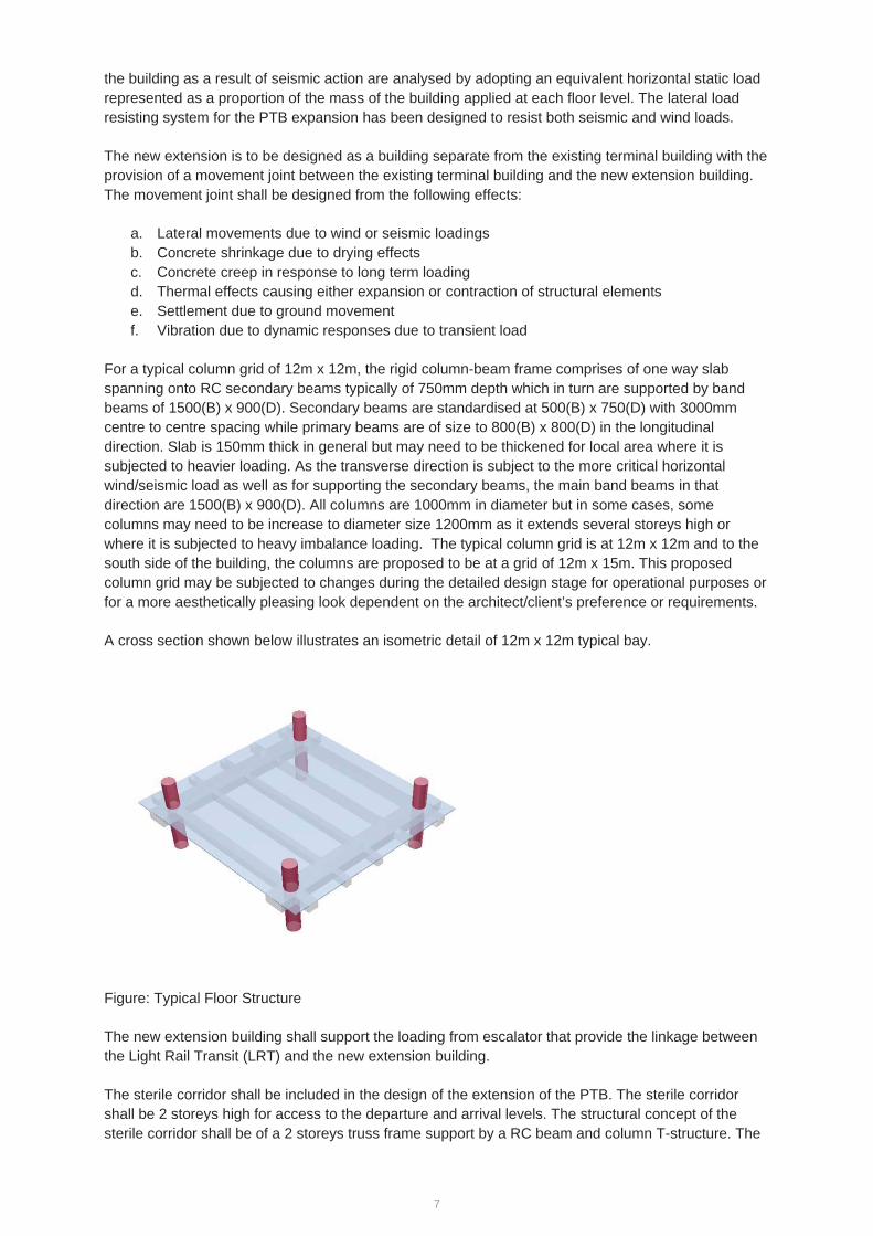
For a typical column grid of 12m x 12m, the rigid column-beam frame comprises of one way slab spanning onto RC secondary beams typically of 750mm depth which in turn are supported by band beams of 1500(B) x 900(D). Secondary beams are standardised at 500(B) x 750(D) with 3000mm centre to centre spacing while primary beams are of size to 800(B) x 800(D) in the longitudinal direction. Slab is 150mm thick in general but may need to be thickened for local area where it is subjected to heavier loading. As the transverse direction is subject to the more critical horizontal wind/seismic load as well as for supporting the secondary beams, the main band beams in that direction are 1500(B) x 900(D). All columns are 1000mm in diameter but in some cases, some columns may need to be increase to diameter size 1200mm as it extends several storeys high or where it is subjected to heavy imbalance loading. The typical column grid is at 12m x 12m and to the south side of the building, the columns are proposed to be at a grid of 12m x 15m. This proposed column grid may be subjected to changes during the detailed design stage for operational purposes or for a more aesthetically pleasing look dependent on the architect/client’s preference or requirements.
A cross section shown below illustrates an isometric detail of 12m x 12m typical bay.
Figure: Typical Floor Structure
The new extension building shall support the loading from escalator that provide the linkage between the Light Rail Transit (LRT) and the new extension building.
The sterile corridor shall be included in the design of the extension of the PTB. The sterile corridor shall be 2 storeys high for access to the departure and arrival levels. The structural concept of the sterile corridor shall be of a 2 storeys truss frame support by a RC beam and column T-structure. The
8
sterile corridor shall also support the loadings from the 2 nos. of Fixed Link Bridges (FLBs). Shallow foundation such as pad/raft footing shall be an appropriate foundation system for the sterile corridor.
The Fixed Link Bridges will be constructed as an independent steel frame supported by RC columns. Each FLB will include a main framing using RHS/SHS box sections or Universal Beams(UB)/Universal Columns(UC) dependent on the preference of the client/architect. From a structural engineering point of view, box sections provide good torsional resistance to the eccentric loadings likely to arise from flooring and/or cladding system connections. Members are anticipated to have truss loading (tension/compression) and bending (due to floor and/or cladding loads). Loadings from the steel frame will then be transferred to the concrete columns below which in turn will also be supported by the proposed pad footings.
For the phase 2/optional work adjacent to the sterile corridor, RC columns at spacing of not more than 15m are to be provided in the longitudinal direction with RC columns at spacing of 12m in the transverse direction. These columns are to be provided for supporting the loadings from the floor structure at the sterile corridor level and also the loadings from the departure level.
If the sterile corridor and the corridor extension are to be built at once as part of the PTB extension, then only two lines of RC columns at spacing of 15m between Gridline A and B are required. The spacing of the RC columns is 12m in the transverse direction.
Given that the existing PTB is found on pad footing, shallow foundation such as pad/raft footings will also be an appropriate foundation solution for the PTB expansion. The proposed shallow foundation will be found on material classified as soft rock moderately weathered or better with an allowable bearing pressure of 1000kPa. The excavation shall continue until founding material that meets the requirements are found to the engineer.
9
2.1 MVAC System
2.1.1 Scope of Works
The Works to be carried out under this section shall include all labours and materials necessary to form a complete Mechanical Ventilation and Air Conditioning (MVAC) System including design, supply, installation, commissioning, tests, adjustments, and maintenance of MVAC Installation. It shall not only include the major items of plant and equipment specified in this section but also include all the incidental sundry components necessary together with the labour for installing such components of the complete execution of the Works and for operation and maintenance of the installation. It shall also include the co-coordination with other Specialist Sub-contractors or other contractors employed by the Employer on the site.
The Contractor shall be responsible for the design, supply, install, test, commission, operate and maintain the MVAC Services for the Macau Airport Passenger Terminal Building (PTB) North Extension and comply with to the Macau code and regulations. The Contractor Designer shall, from time to time during the development of the design, prepare all design in full compliance with all relevant statutory requirements and the specifications. He shall prepare and submit all relevant design reports, calculation and drawings as necessary in good quality to the client for consent. The contractor shall provide site survey to the existing MIA, study, design submission, material fabrication, delivery, installation, testing and commissioning of the MVAC system so as to ensure new system can be fully operation as independent plant system from existing PTB services.
The Contractor shall liaise with Authority and Client at very early stage of the project to obtain the approval in principle for the proposed scope of fire service installations to be provided for Macau Airport Passenger Terminal Building (PTB) North Extension. If necessary the contractor shall adopt Performance based fire engineering evaluation, studies and analysis required for determining the adequacy of all necessary smoke control and extraction provisions and to the completion of the smoke control and extraction installation to the satisfaction of the authority and the Client.
The contractor shall complete the MVAC Services installation for the new extension development and shall include and not limited to the following MVAC Services systems: Water Cooled Chiller System, Fresh Water Cooling Tower Systems, Chilled Water and Condensing Water Distribution Systems, Air-handling System, Mechanical Ventilation System, associated Control and Monitoring Systems throughout new Macau Airport Passenger Terminal Building (PTB) North Extension.
The Works shall be carried out in a manner consistent with good practice in Macau and to the satisfaction of the Client. The equipment and materials used in the Contract shall have proven reliability and performance.
2 Electrical & Mechanical Works
10
2.1.2 Design Standards
The current codes, rules and regulations established by the following authorities and utility companies: Direccao dos Servicos de obras Publicas e Transportes (DSSOPT) – Applicable codes and
standards Regulamento de Seguranca Contra incendios (RSCI) – Dec.Lei 24/95/M of 09.06.1995 Regulamento de Aguas e de Drenagem de Aguas Residuais de Macau (RADARM)) (Dec. Lei
46/96/M of 19.08.1996) RSIUEE - Regulamento de Seguranca de Instalacoes de Utilizacao de Energia Electrica (RSIUEE) (Dec. Lei 740/74 of 26.12.1974) RSICEE - Regulamento de Seguranca de Instalacoes Colectivas de Edificios e Entradas
(Dec. Lei 740/74 of 26.12.1974) Companhia de Electrcidade de Macau (CEM) – Supply Rules and Relevant Electricity Supply
Ordinance Servico de Abastecimento de Aguas de Macau (Macau Water) – Supply Rules and Relevant
Water Supply Ordinance Companhia de Telecomunicacoes de Macau (CTM) – Supply Rules and Relevant Communications Supply Ordinance Institituto para os Assuntos Civicos e Municipais (IACM) – Recomendations and codes of
practices Hong Kong Building Energy Efficiency Ordinance from EMSD HKSAR Any other authorities having jurisdiction over the installation
The installation materials and equipment shall comply with the latest requirements of the standard codes, guides and other documents issued by the authorities, institutions and organizations referred to in various sections of the Specifications, including the following:
BSI British Standard Institution CIBSE Chartered Institution of Building Services Engineers IEE Institution of Electrical Engineers ISO Institution of Electrical Engineers IEC International Electro-technical Committee DIN International Standard ASHRAE American Society of Heating, Refrigeration and Air-Conditioning Engineers, Inc. IMC International Mechanical Code JIS Japanese International Standard NFPA National Fire Protection Association UL Underwriters Laboratory, Inc.
Design Criteria
Outdoor Design Conditions:
Summer: 33.5 deg C DB, 68% RH
Winter: 7.0 deg C DB, 40% RH
11
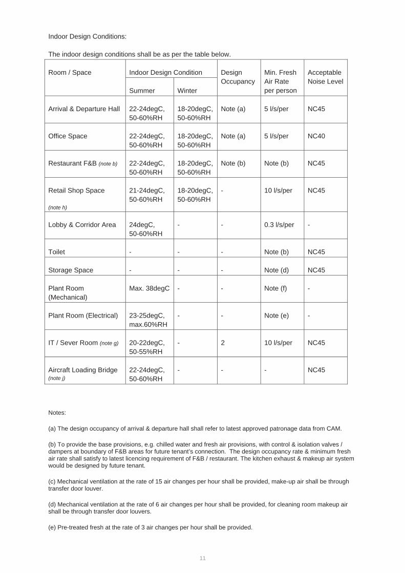
Indoor Design Conditions:
The indoor design conditions shall be as per the table below.
Room / Space Indoor Design Condition Design Occupancy
Min. Fresh Air Rate per person
Acceptable Noise Level
Summer Winter
Arrival & Departure Hall 22-24degC, 50-60%RH
18-20degC, 50-60%RH
Note (a) 5 l/s/per NC45
Office Space 22-24degC, 50-60%RH
18-20degC, 50-60%RH
Note (a) 5 l/s/per NC40
Restaurant F&B (note b) 22-24degC, 50-60%RH
18-20degC, 50-60%RH
Note (b) Note (b) NC45
Retail Shop Space
(note h)
21-24degC, 50-60%RH
18-20degC, 50-60%RH
- 10 l/s/per NC45
Lobby & Corridor Area 24degC, 50-60%RH
- - 0.3 l/s/per -
Toilet - - - Note (b) NC45
Storage Space - - - Note (d) NC45
Plant Room (Mechanical)
Max. 38degC - - Note (f) -
Plant Room (Electrical) 23-25degC, max.60%RH
- - Note (e) -
IT / Sever Room (note g) 20-22degC, 50-55%RH
- 2 10 l/s/per NC45
Aircraft Loading Bridge (note j)
22-24degC, 50-60%RH
- - - NC45
Notes:
(a) The design occupancy of arrival & departure hall shall refer to latest approved patronage data from CAM.
(b) To provide the base provisions, e.g. chilled water and fresh air provisions, with control & isolation valves / dampers at boundary of F&B areas for future tenant’s connection. The design occupancy rate & minimum fresh air rate shall satisfy to latest licencing requirement of F&B / restaurant. The kitchen exhaust & makeup air system would be designed by future tenant.
(c) Mechanical ventilation at the rate of 15 air changes per hour shall be provided, make-up air shall be through transfer door louver.
(d) Mechanical ventilation at the rate of 6 air changes per hour shall be provided, for cleaning room makeup air shall be through transfer door louvers.
(e) Pre-treated fresh at the rate of 3 air changes per hour shall be provided.

12
(f) Mechanical ventilation shall be provided to maintain plant room temperature at conditions of below 38degC.
(g) Computer Room Air-Conditioning (CRAC) system shall be provided for accurate control of temperature and relative humidity within the IT/Sever facility rooms.
(h) To provide the base provisions, e.g. chilled water and fresh air provisions, with control & isolation valves / dampers at boundary of F&B areas for future tenant’s connection.
(j) Split type air-conditioning system with condensing unit mounted locally at ALB to be provided.
Mechanical Smoke Control / Extraction system shall be provided for Arrival & Departure Concourses, Retails where appropriate. Same fire and smoke control strategy on existing terminal concourses would be followed. The design of smoke control system shall comply with the requirements of NFPA 92, CB (“Corpo de Bomberios”) and Macau fire safety code requirements. In the event of conflict between these standards, NFPA 92 and relevant requirements shall be followed.
Internal Loads
The air-conditioning loads shall comply with the requirements as stated in the latest ASHRAE Handbook – HVAC Applications recommendations and details are described as per the followings:
Occupancy
The occupancy considered for the cooling load calculations shall follow the approved occupancy data given from CAM.
Fresh Air Supply
The fresh air considered for the cooling load calculations shall be: 1. Public concourse areas: 5 l/s/person 2. Office Areas: 10 l/s/person 3. Air-conditioned Corridors ,Lobby and Storage Areas: 0.3 l/s/m2 4. Any Other Areas: As per ASHRAE 62.1-2013 Guidelines.
Heat Dissipation from People
The heat gain due to occupants considered in the cooling load calculation shall be: 1. Public concourse areas Sensible Heat gain - 75 W/person
Latent heat gain - 70 W/person 2. Office Areas Sensible Heat gain - 75 W/person
Latent heat gain - 55 W/person
Heat Dissipation from Lights
The heat dissipation from general lights (not including any theme or architectural feature lights) considered in the cooling load calculation shall be:
1. Public concourse areas- Sensible Heat gain - 20 W/m2 2. Equipment plant rooms - Sensible Heat gain - 12 W/m2
13
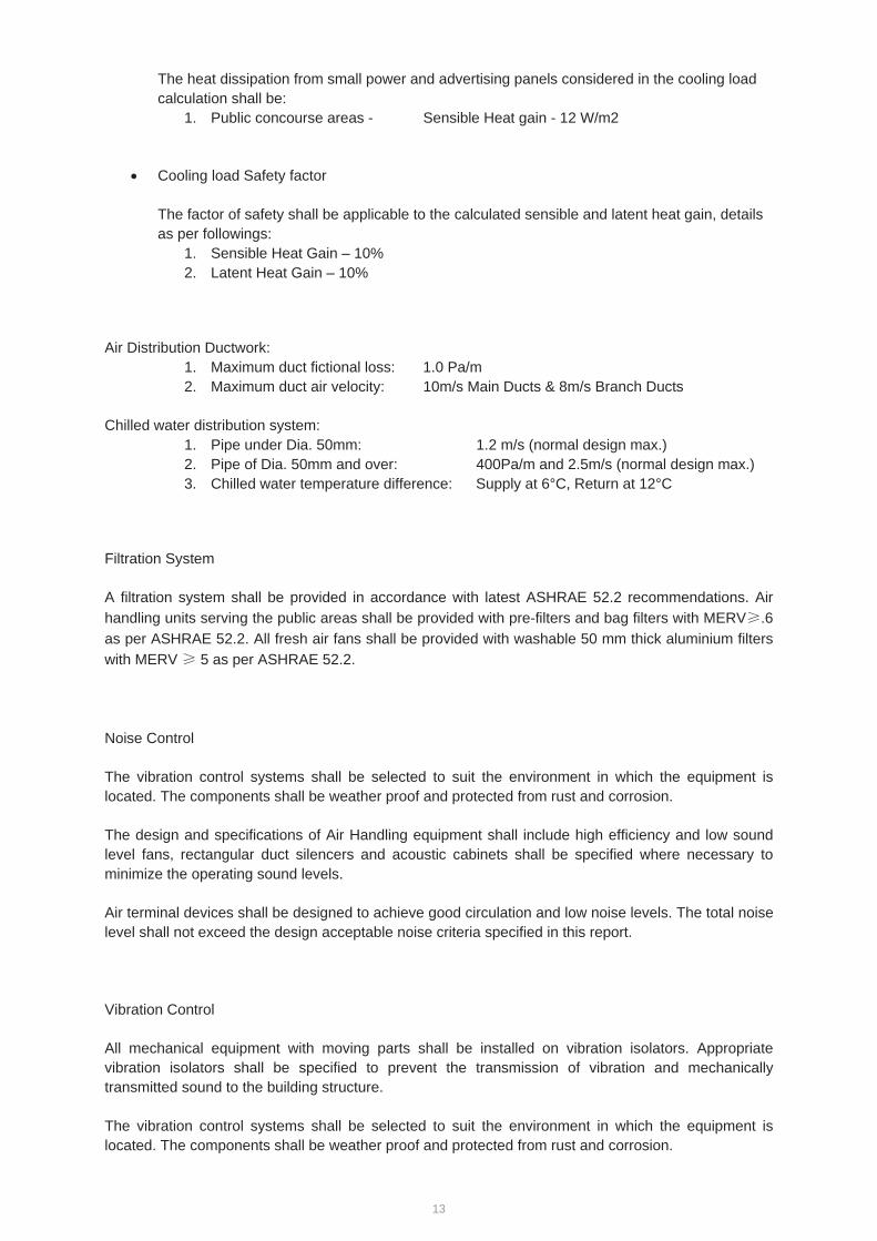
The heat dissipation from small power and advertising panels considered in the cooling load calculation shall be:
1. Public concourse areas - Sensible Heat gain - 12 W/m2
Cooling load Safety factor
The factor of safety shall be applicable to the calculated sensible and latent heat gain, details as per followings:
1. Sensible Heat Gain – 10% 2. Latent Heat Gain – 10%
Air Distribution Ductwork: 1. Maximum duct fictional loss: 1.0 Pa/m 2. Maximum duct air velocity: 10m/s Main Ducts & 8m/s Branch Ducts
Chilled water distribution system: 1. Pipe under Dia. 50mm: 1.2 m/s (normal design max.) 2. Pipe of Dia. 50mm and over: 400Pa/m and 2.5m/s (normal design max.) 3. Chilled water temperature difference: Supply at 6°C, Return at 12°C
Filtration System
A filtration system shall be provided in accordance with latest ASHRAE 52.2 recommendations. Air handling units serving the public areas shall be provided with pre-filters and bag filters with MERV .6 as per ASHRAE 52.2. All fresh air fans shall be provided with washable 50 mm thick aluminium filters with MERV 5 as per ASHRAE 52.2.
Noise Control
The vibration control systems shall be selected to suit the environment in which the equipment is located. The components shall be weather proof and protected from rust and corrosion.
The design and specifications of Air Handling equipment shall include high efficiency and low sound level fans, rectangular duct silencers and acoustic cabinets shall be specified where necessary to minimize the operating sound levels.
Air terminal devices shall be designed to achieve good circulation and low noise levels. The total noise level shall not exceed the design acceptable noise criteria specified in this report.
Vibration Control
All mechanical equipment with moving parts shall be installed on vibration isolators. Appropriate vibration isolators shall be specified to prevent the transmission of vibration and mechanically transmitted sound to the building structure.
The vibration control systems shall be selected to suit the environment in which the equipment is located. The components shall be weather proof and protected from rust and corrosion.
14
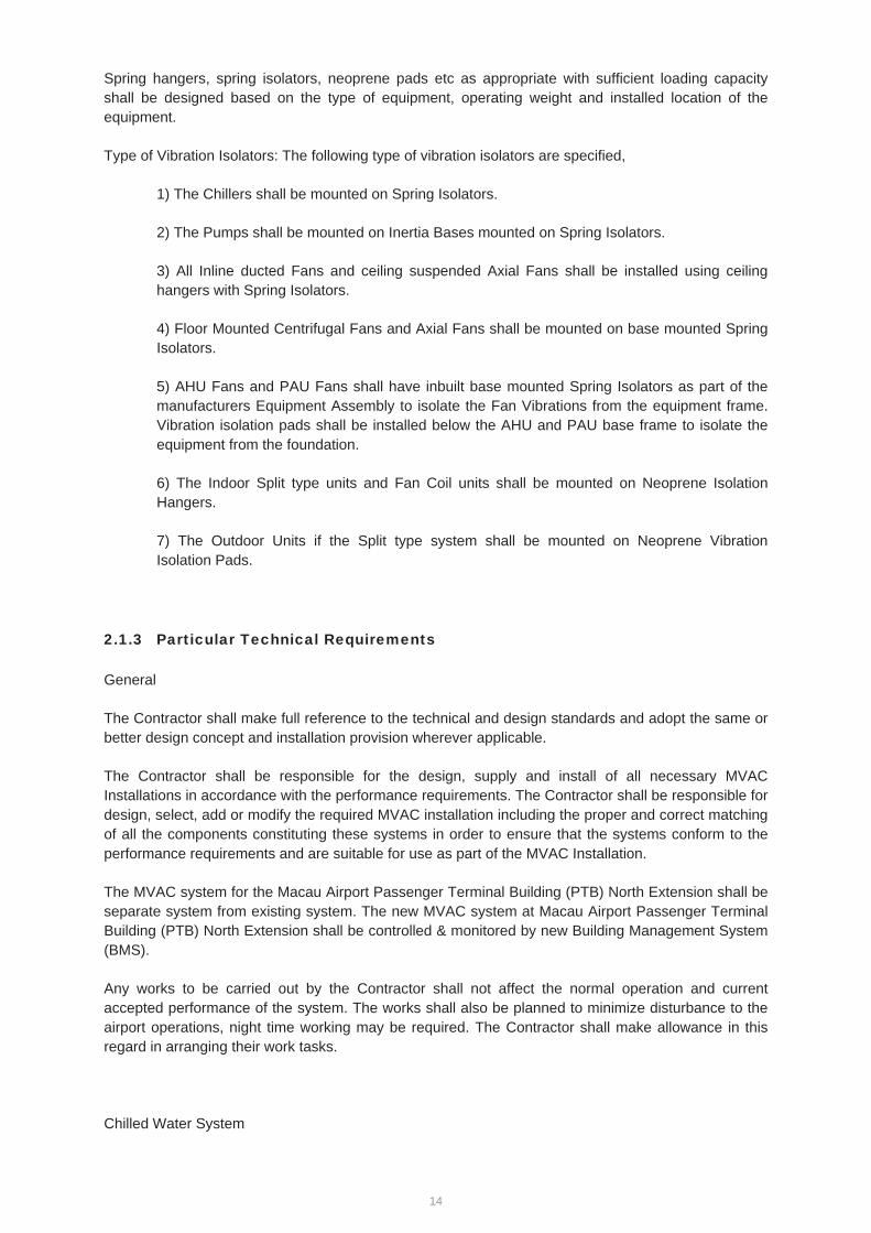
Spring hangers, spring isolators, neoprene pads etc as appropriate with sufficient loading capacity shall be designed based on the type of equipment, operating weight and installed location of the equipment.
Type of Vibration Isolators: The following type of vibration isolators are specified,
1) The Chillers shall be mounted on Spring Isolators.
2) The Pumps shall be mounted on Inertia Bases mounted on Spring Isolators.
3) All Inline ducted Fans and ceiling suspended Axial Fans shall be installed using ceiling hangers with Spring Isolators.
4) Floor Mounted Centrifugal Fans and Axial Fans shall be mounted on base mounted Spring Isolators.
5) AHU Fans and PAU Fans shall have inbuilt base mounted Spring Isolators as part of the manufacturers Equipment Assembly to isolate the Fan Vibrations from the equipment frame. Vibration isolation pads shall be installed below the AHU and PAU base frame to isolate the equipment from the foundation.
6) The Indoor Split type units and Fan Coil units shall be mounted on Neoprene Isolation Hangers.
7) The Outdoor Units if the Split type system shall be mounted on Neoprene Vibration Isolation Pads.
2.1.3 Particular Technical Requirements
General
The Contractor shall make full reference to the technical and design standards and adopt the same or better design concept and installation provision wherever applicable.
The Contractor shall be responsible for the design, supply and install of all necessary MVAC Installations in accordance with the performance requirements. The Contractor shall be responsible for design, select, add or modify the required MVAC installation including the proper and correct matching of all the components constituting these systems in order to ensure that the systems conform to the performance requirements and are suitable for use as part of the MVAC Installation.
The MVAC system for the Macau Airport Passenger Terminal Building (PTB) North Extension shall be separate system from existing system. The new MVAC system at Macau Airport Passenger Terminal Building (PTB) North Extension shall be controlled & monitored by new Building Management System (BMS).
Any works to be carried out by the Contractor shall not affect the normal operation and current accepted performance of the system. The works shall also be planned to minimize disturbance to the airport operations, night time working may be required. The Contractor shall make allowance in this regard in arranging their work tasks.
Chilled Water System
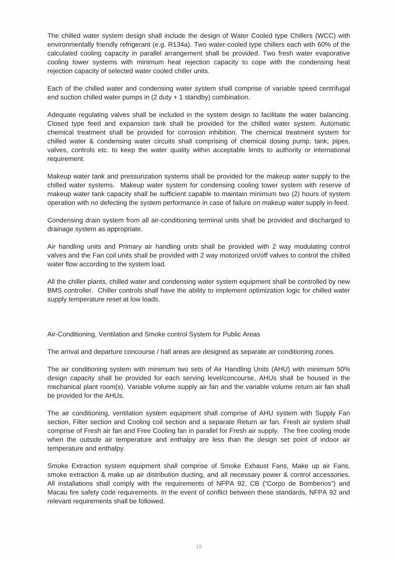
15
The chilled water system design shall include the design of Water Cooled type Chillers (WCC) with environmentally friendly refrigerant (e.g. R134a). Two water-cooled type chillers each with 60% of the calculated cooling capacity in parallel arrangement shall be provided. Two fresh water evaporative cooling tower systems with minimum heat rejection capacity to cope with the condensing heat rejection capacity of selected water cooled chiller units.
Each of the chilled water and condensing water system shall comprise of variable speed centrifugal end suction chilled water pumps in (2 duty + 1 standby) combination.
Adequate regulating valves shall be included in the system design to facilitate the water balancing. Closed type feed and expansion tank shall be provided for the chilled water system. Automatic chemical treatment shall be provided for corrosion inhibition. The chemical treatment system for chilled water & condensing water circuits shall comprising of chemical dosing pump, tank, pipes, valves, controls etc. to keep the water quality within acceptable limits to authority or international requirement.
Makeup water tank and pressurization systems shall be provided for the makeup water supply to the chilled water systems. Makeup water system for condensing cooling tower system with reserve of makeup water tank capacity shall be sufficient capable to maintain minimum two (2) hours of system operation with no defecting the system performance in case of failure on makeup water supply in-feed.
Condensing drain system from all air-conditioning terminal units shall be provided and discharged to drainage system as appropriate.
Air handling units and Primary air handling units shall be provided with 2 way modulating control valves and the Fan coil units shall be provided with 2 way motorized on/off valves to control the chilled water flow according to the system load.
All the chiller plants, chilled water and condensing water system equipment shall be controlled by new BMS controller. Chiller controls shall have the ability to implement optimization logic for chilled water supply temperature reset at low loads.
Air-Conditioning, Ventilation and Smoke control System for Public Areas
The arrival and departure concourse / hall areas are designed as separate air conditioning zones.
The air conditioning system with minimum two sets of Air Handling Units (AHU) with minimum 50% design capacity shall be provided for each serving level/concourse, AHUs shall be housed in the mechanical plant room(s). Variable volume supply air fan and the variable volume return air fan shall be provided for the AHUs.
The air conditioning, ventilation system equipment shall comprise of AHU system with Supply Fan section, Filter section and Cooling coil section and a separate Return air fan. Fresh air system shall comprise of Fresh air fan and Free Cooling fan in parallel for Fresh air supply. The free cooling mode when the outside air temperature and enthalpy are less than the design set point of indoor air temperature and enthalpy.
Smoke Extraction system equipment shall comprise of Smoke Exhaust Fans, Make up air Fans, smoke extraction & make up air distribution ducting, and all necessary power & control accessories. All installations shall comply with the requirements of NFPA 92, CB (“Corpo de Bomberios”) and Macau fire safety code requirements. In the event of conflict between these standards, NFPA 92 and relevant requirements shall be followed.

16
An exhaust system shall be designed for the toilets and cleaning rooms where the discharge air shall be connected to the external exhaust air louver at location without short circuiting to any building fresh air intake points.
Automatic Controls
The MVAC plant and equipment shall be controlled & monitored by BMS via the DDCs. The DDCs shall be provided where appropriate in the Plant room for the Chillers, Pumps, AHUs, cooling tower & ventilation systems, etc
The BMS shall control and monitor the following equipment: Chillers. Chilled water Pumps Cooling Towers Condensing water Pumps Air Handling Units (AHU) and Pre-treated Air Handling Unit (PAU) Fan Coil Units (FCU) Ventilation fans for fresh air and exhaust. Pressurization unit for the makeup water system. MVAC related Motorized dampers. Field sensors and switches. Power Factor Correction. Surge Protection. Main Air Circuit breaker status KWhr meter consumption Multi function meter (Voltage, Amperes, Harmonics, Power Factor, kVA, etc) All other equipment to suit the requirement of Authority & Client.
Temperature and Humidity sensors shall be located at various locations to measure the indoor and outdoor conditions. The BMS shall be programmed to enable the free cooling mode when the outside air temperature and enthalpy are less than the indoor air temperature and enthalpy.
CO2 sensors shall be provided in the return air ducts to measure the CO2 levels in the concourse areas. The modulating type return and fresh air dampers are designed to provide optimum fresh air as per the measured CO2 levels.
Dry contact shall be provided from the ventilation RI/O or I/O modules for VAC shut down control of the non-emergency equipment in case of fire.
MVAC system for non-Public Areas
Offices
Centralized Air conditioning system using AHU and associated supply distribution & return air ducting system; shall be provided for office areas.
Toilet
Mechanical exhaust system shall be provided for all male and female toilets with mechanical exhaust capacity of not less than 15 air changes per hour to the toilets. The exhaust system shall comprise of Inline centrifugal duct type exhaust fan with exhaust air ducts connected to the exhaust grilles for
17
discharge, and the exhaust air discharge shall arranged at location without short circuiting to any building fresh air intake points.
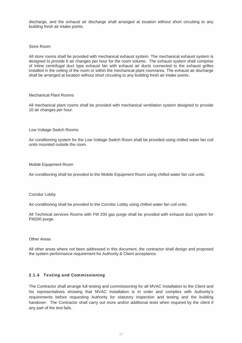
Store Room
All store rooms shall be provided with mechanical exhaust system. The mechanical exhaust system is designed to provide 6 air changes per hour for the room volume. The exhaust system shall comprise of Inline centrifugal duct type exhaust fan with exhaust air ducts connected to the exhaust grilles installed in the ceiling of the room or within the mechanical plant room/area. The exhaust air discharge shall be arranged at location without short circuiting to any building fresh air intake points.
Mechanical Plant Rooms
All mechanical plant rooms shall be provided with mechanical ventilation system designed to provide 10 air changes per hour.
Low Voltage Switch Rooms
Air conditioning system for the Low Voltage Switch Room shall be provided using chilled water fan coil units mounted outside the room.
Mobile Equipment Room
Air-conditioning shall be provided to the Mobile Equipment Room using chilled water fan coil units.
Corridor Lobby
Air-conditioning shall be provided to the Corridor Lobby using chilled water fan coil units.
All Technical services Rooms with FM 200 gas purge shall be provided with exhaust duct system for FM200 purge.
Other Areas
All other areas where not been addressed in this document, the contractor shall design and proposed the system performance requirement for Authority & Client acceptance.
2.1.4 Testing and Commissioning
The Contractor shall arrange full testing and commissioning for all MVAC Installation to the Client and his representatives showing that MVAC Installation is in order and complies with Authority’s requirements before requesting Authority for statutory inspection and testing and the building handover. The Contractor shall carry out more and/or additional tests when required by the client if any part of the test fails.

18
The Contractor shall allow adequate time in his programme for the test and re-testing before completion of the Contract.
The Contractor shall liaise with all concerned parties for the timely completion of all works affecting the final MVAC Installation inspection by Authority including normal and essential electricity supply, all related builder’s works, etc. before the submission of relevant application forms to Authority requesting for inspection.
The Contractor shall carry out all tests for equipment and installation to be covered up before proceeding further any work, such as hydraulic test for MVAC Installation piping before the installation of false ceiling, etc. to the satisfaction of the to the Client and his representatives. The Contractor shall be liable of all possible consequences if he fails to do so.
The Contractor shall submit the testing and commissioning details for the review without objection by the CAM Project Manager before implementation.
19
2.2 Fire Services System
2.2.1 Scope of Works
The Works to be carried out under this section shall include all labours and materials necessary to form a complete Fire Service Installation including design, supply, installation, commissioning, tests, adjustments, and maintenance of Fire Service Installation. It shall not only include the major items of plant and equipment specified in this section but also include all the incidental sundry components necessary together with the labour for installing such components of the complete execution of the Works and for operation and maintenance of the installation. It shall also include the co-coordination with other Specialist Sub-contractors or other contractors employed by the Employer on the site.
The Contractor shall be responsible for the design, supply, install, test, commission, operate and maintain the Fire Services for the Macau Airport Passenger Terminal Building (PTB) North Extension and associated works and comply with to the Macau Fire Services regulation and other code and regulations and shall obtain all statutory approvals for the works. The Contractor Designer shall, from time to time during the development of the design, prepare all design in full compliance with all relevant statutory requirements and the specifications. He shall prepare and submit all relevant design reports, calculation and drawings as necessary in good quality to the client for consent. The contractor shall carry out building services and structural site survey and utilities survey both aboveground and underground works to the existing Macau International Airport in associated to the Macau Airport Passenger Terminal Building (PTB) North Extension Works, study, design submissions, material fabrication and material submission, delivery, installation, testing and commissioning of the Fire Services system so as to ensure new system can be fully interface and integrated with the existing system.
The Contractor shall liaise with Macau Authority and Client at very early stage of the project to obtain the approval in principle for the proposed scope of fire service installations to be provided for Macau Airport Passenger Terminal Building (PTB) North Extension. If necessary the contractor shall adopt Performance based fire engineering evaluation, studies and analysis required for the completion of the installation and for determining the adequacy of all necessary fire safety provisions (both passive and active means) to the satisfaction of the authority and the Client.
The contractor shall complete the Fire Services installation for the new development and obtain all statuary approval and it shall include and not limited to the following Fire Services systems: Automatic Fire Detection and Fire Alarm Systems/ Fire Hydrant / Hose reel System/ Clean Agent Fire Extinguishing Systems / Automatic Sprinkler System/ Street Fire Hydrant System both at landside and airside/ Water Connection and Portable hand operated approved appliance throughout and for the new Macau Airport Passenger Terminal Building (PTB) North Extension.
The Works shall be carried out in a manner consistent with good practice in Macau and to the satisfaction of the Client. The equipment and materials used in the Contract shall have proven reliability and performance and should be with job reference with Macau International Airport/ Hong Kong International Airport or equivalent.
2.2.2 Design Standards
Fire Services Systems for development are designed based on and shall comply with following codes:
The Contractor shall make full reference to the technical and design standards/specifications appended as annexes of this section and adopt the same or better design concept and installation provision wherever applicable.
Macau Fire Services regulation “ Regulamento de Seguranca Contra Incendios” and Decree Law 24/95/M
Direcção dos Serviços de obras Públicas e Transportes (DSSOPT) – Applicable codes and standards
Regulamento de Segurança Contra incêndios (RSCI) – Dec.Lei 24/95/M of 09.06.1995
Regulamento de Águas e de Drenagem de Águas Residuais de Macau (RADARM)) (Dec. Lei 46/96/M of 19.08.1996)
20
RSIUEE - Regulamento de Segurança de Instalações de Utilização de Energia Eléctrica (RSIUEE) (Dec. Lei 740/74 of 26.12.1974)
RSICEE - Regulamento de Segurança de Instalações Colectivas de Edificios e Entradas (Dec. Lei 740/74 of 26.12.1974)
Companhia de Electrcidade de Macau (CEM) – Supply Rules and Relevant Electricity Supply Ordinance
Serviço de Abastecimento de Águas de Macau (Macau Water) – Supply Rules and Relevant Water Supply Ordinance
Companhia de Telecomunicações de Macau (CTM) – Supply Rules and Relevant Communications Supply Ordinance
Institituto para os Assuntos Civicos e Municipais (IACM) – Recomendations and codes of practices
NFPA 72 –National Fire Alarm Code
NFPA 130 – Standard for Fixed Guideway Transit and Passenger Rail Systems
NFPA 2001 – Standard on Clean Agent Fire Extinguishing Systems
The installation materials and equipment shall be supplied and installed using the best available quality materials and workmanship and shall comply with the latest requirements of the standard codes, guides and other documents issued by the authorities, institutions and organizations referred to in various sections of the Specifications, including the following:
BSI British Standard Institution
CIBSE Chartered Institution of Building Services Engineers
IEE Institution of Electrical Engineers
ISO Institution of Electrical Engineers
IEC International Electrotechnical Committee
DIN International Standard
ASHRAE American Society of Heating, Refrigeration and Air-Conditioning Engineers, Inc.
IPC International Plumbing Code
JIS Japanese International Standard
NFPA National Fire Protection Association
The Contractor shall adopt the latest development in the technology and use hi-tech, reliable, flexible, environmental friendly and sustainable system and equipment to formulate the final design. The Contractor shall at an early design stage liaise and consult with the relevant Government Departments, Authorities and Utility Undertakings such as Fire Services Department, Water Supplies Department, Environmental Protection Department and Power Company etc. to obtain their requirements for incorporation into the design.
2.2.3 Particular Technical Requirements
The Contractor shall make full reference to the technical and design standards and adopt the same or better design concept and installation provision wherever applicable
The Contractor shall be responsible for the design, supply and install testing and commissioning of all necessary Fire Service Installations in accordance with the performance requirements. The Contractor shall be responsible for design, select, add or modify the required fire service installation including the proper and correct matching of all the components constituting these systems in order to ensure that the systems conform to the performance requirements and are suitable for use as part of the Fire Service Installation.
21
The Fire Alarm and Detection system for the Macau Airport Passenger Terminal Building (PTB) North Extension shall be separate system and independent system from existing buildings systems. The contractor shall house the proposed AFA main panel within a FS control room and the location shall subject to Client approval. Fire Alarm signals from Macau Airport Passenger Terminal Building (PTB) North Extension shall be repeated to exiting Fire Services control centre for control and reporting. The Contractor shall be responsible in ensure in the new proposed Fire Services installation can compatible with existing Fire system the Automatic Fire alarm system, etc. All the fire signals shall be repeated to existing two control points. The contractor shall allow adequate interfacing points at the FS control room for others to connect and repeat the signals and for control/ operation of existing Fire Services installation. Should there be any modification, reconfiguration or addition of Fire Services installation, the overall system performance of the existing Fire Services installation system shall not be degraded in any form.
Performance at fire and reliability are two key requirements in the selection of The Fire Alarm and Detection system. The FS Contractor shall supply and install highly reliable approved manual and automatic fire alarm systems that have a good record of ‘no false fire alarm’ and ‘no malfunctioning’ in the past years. Substantiation on a good record of reliability shall be obtained from the suppliers and submitted to the Architect. System that has a poor false alarm record or has failed to provide the required record when asked will not be accepted for the Installations. Only equipment that suits the operating environment shall be selected and used. Manual and automatic fire alarm initiating devices shall be appropriately sited to avoid factors that can generate false fire alarms. At locations where the relative humidity is higher than 95% continuous non-condensing such as in non-air-conditioned space, the FS Contractor shall use detectors of harsh type or of appropriate design specially made for harsh environment and high humidity application up to relative humidity 99% continuous non-condensing. At dusty or windy environment, appropriate filtering and shielding devices shall be added to the detectors. At external area or covered area that can be subject to rainwater at wind condition, waterproof equipment shall be used. Appropriate type of surge protective device shall be supplied and installed in the electrical and control circuits for suppression of over-voltage surges arising from lightning strikes and switching transient. Manual and automatic fire alarm system shall be of analogue addressable type except for system with manual fire alarm only. The rate of false fire alarms, excluding false fire alarms arising from malicious actions by humans and false fire alarms with good intent involving genuine belief of a fire, shall not be more than one false fire alarm per 100 fire alarm initiating devices per annum for all the Installations in a building, and shall not be more than one false fire alarm per 80 automatic detectors per annum for the automatic fire alarm system. The FS Contractor shall be responsible to limit the false fire alarms in the process of equipment selection, choosing suppliers, types and brands, whole system integration, installation, siting, testing, commissioning, cleaning/maintenance, and verification of manufacturer’s test records and quality control standards. The FS Contractor shall only select brands and models of equipment and materials that have good track record or job reference of meeting the above requirement on the rate of false fire alarms. The Contractor shall allow at least 25% spare at each detection loop for future expansion/ use. Fire service computer system shall be supplied and installed. Fire service computer system shall comprise a computer system and Sever for indication and monitoring of the operational status of fire service equipment and fire alarms. The computer system shall be used to facilitate the management and maintenance of the Installations. The computer system shall not interfere with the operation of the fire alarm control system. When the computer system is down or has faults, the fire alarm control system shall still perform without any interruption. Fire service computer system can be part of an integrated computer system for indication and monitoring of all building services systems in a building. Web-based computer software shall be preferred and shall be adopted unless otherwise approved by the Architect. Facilities shall also be built-in for easy monitoring and access of the fire service computer system from a remote site through the Internet when needed. Details and associated software of the fire service computer system shall be submitted to the Client for approval. All the fire signals including the common alarm signal shall be repeated to the BMS systems for monitoring. The Fire alarm and detection system shall also interface with and not limited to the following systems the electrical system, lift system, access door control system, public address system and HVAC systems for Ventilation/ Air conditioning control system and Smoke extraction system if necessary.
For the Fire Services Wet systems, they shall be independent and separate system from the existing Fire Services systems at other buildings within the Macau International Airport. For the project Macau Airport Passenger Terminal Building (PTB) North Extension and associated works area the
22
new systems, the contractor may consider to connect to respectively FS main from existing network FS water supply network. The Contractor shall submit detailed proposal including detailed calculation to the Client and his representatives for approval. In the proposal, the Contractor shall demonstrate the design of the proposed system can cater for the Macau Airport Passenger Terminal Building (PTB) North Extension and the existing development as well The Contractor shall be responsible for any upgrading of the existing systems including but not limited to FS pumps, sprinkler pumps, street hydrant pumps and water tank,etc if necessary. In an alternative, the Contractor shall allow its own cost to build an independent Fire Services for the new Macau Airport Passenger Terminal Building (PTB) North Extension.
Clean Agent Fire Extinguishing Systems – Novec 1230 [complying to NFPA] shall be employed for this project for the protection of Electrical/ ELV equipment rooms and Electrical / ELVplant rooms including but not limited to battery room, Lan server room, ELV control room, ELV equipment rooms, etc.
Any works to be carried out by the Contractor shall not affect the normal operation and current accepted performance of the system. The works shall also be planned to minimize disturbance to the airport operations, night time working may be required. The Contractor shall make allowance in this regard in arranging their work tasks.
2.2.4 Testing and Commissioning
The Contractor shall arrange full testing and commissioning for all fire service installation to the Client and his representatives showing that the fire service installation is in order and complies with Authority’s requirements before requesting Authority for statutory inspection and testing and the building handover. The Contractor shall carry out more and/or additional tests when required by the client if any part of the test fails.
The Contractor shall allow adequate time in his programme for the test and re-testing before completion of the Contract.
The Contractor shall liaise with all concerned parties for the timely completion of all works affecting the final fire services inspection by Authority including portable firefighting equipment, water supplies, EXIT signs, the whole Fire Service Installation, normal and essential electricity supply, control of the A/C works, fireman’s lift, all related builder’s works, etc. before the submission of relevant application forms to Authority requesting for inspection.
The Contractor shall carry out all tests for equipment and installation to be covered up before proceeding further any work, such as hydraulic test for sprinkler system piping before the installation of false ceiling, etc. to the satisfaction of the to the Client and his representatives. The Contractor shall be liable of all possible consequences if he fails to do so.
The Contractor shall submit the testing and commissioning details for the review without objection by the CAM Project Manager before implementation.
23
2.3 Plumbing & Drainage System
2.3.1 Scope of Works
The Works to be carried out under this section shall include all labours and materials necessary to form a complete Plumbing and Drainage Service Installation including design, supply, installation, commissioning, tests, adjustments, and maintenance of Plumbing and Drainage Service Installation. It shall not only include the major items of plant and equipment specified in this section but also include all the incidental sundry components necessary together with the labour for installing such components of the complete execution of the Works and for operation and maintenance of the installation. It shall also include the co-coordination with other Specialist Sub-contractors or other contractors employed by the Employer on the site.
The Contractor shall be responsible for the design, supply, install, test, commission, operate and maintain the Plumbing and Drainage Service Installation both aboveground and underground for Macau Airport Passenger Terminal Building (PTB) North Extension and comply with to the Macau code and regulations and shall obtain all statutory approvals for the works. The Contractor Designer shall, from time to time during the development of the design, prepare all design in full compliance with all relevant statutory requirements and the specifications. He shall prepare and submit all relevant design reports, calculation and drawings as necessary in good quality to the client for consent. The contractor shall provide building services and structural site survey and utilities survey both aboveground and underground works to the existing Macau International Airport in associated to the Macau Airport Passenger Terminal Building (PTB) North Extension Works, study, design submission, material fabrication, delivery, installation, testing and commissioning of the Plumbing and Drainage Service Installation so as to ensure new system can be fully interface and integrated with the existing system.
The Works shall be carried out in a manner consistent with good practice in Macau and to the satisfaction of the Client. The equipment and materials used in the Contract shall have proven reliability and performance and should be with job reference with Macau International Airport/ Hong Kong International Airport or equivalent.
2.3.2 Design Standards
The plumbing and drainage system works shall comply with the current rules and regulations established by the following authorities and utility companies:
Direcção dos Serviços de obras Públicas e Transportes (DSSOPT) – Applicable codes and standards
Regulamento de Segurança Contra incêndios (RSCI) – Dec.Lei 24/95/M of 09.06.1995
Regulamento de Águas e de Drenagem de Águas Residuais de Macau (RADARM)) (Dec. Lei 46/96/M of 19.08.1996)
RSIUEE - Regulamento de Segurança de Instalações de Utilização de Energia Eléctrica (RSIUEE) (Dec. Lei 740/74 of 26.12.1974)
RSICEE - Regulamento de Segurança de Instalações Colectivas de Edificios e Entradas (Dec. Lei 740/74 of 26.12.1974)
Companhia de Electrcidade de Macau (CEM) – Supply Rules and Relevant Electricity Supply Ordinance
Serviço de Abastecimento de Águas de Macau (Macau Water) – Supply Rules and Relevant Water Supply Ordinance
Companhia de Telecomunicações de Macau (CTM) – Supply Rules and Relevant Communications Supply Ordinance
Institituto para os Assuntos Civicos e Municipais (IACM) – Recomendations and codes of practices
Any other authorities having jurisdiction over the installation
24
The design of external terminal building plumbing and drainage systems shall be carried out according to Macau Code ‘Macau Regulation 46/96/M for Plumbing and Drainage Installation (RADARM)’.
The installation materials and equipment shall be supplied and installed using the best available quality materials and workmanship and shall comply with the latest requirements of the standard codes, guides and other documents issued by the authorities, institutions and organizations referred to in various sections of the Specifications, including the following:
BSI British Standard Institution
CIBSE Chartered Institution of Building Services Engineers
IEE Institution of Electrical Engineers
ISO Institution of Electrical Engineers
IEC International Electrotechnical Committee
DIN International Standard
ASHRAE American Society of Heating, Refrigeration and Air-Conditioning Engineers, Inc.
IPC International Plumbing Code
JIS Japanese International Standard
NFPA National Fire Protection Association
UL Underwriters Laboratory, Inc.
The Contractor shall adopt the latest development in the technology and use hi-tech, reliable, flexible, environmental friendly and sustainable system and equipment to formulate the final design. The Contractor shall at an early design stage liaise and consult with the relevant Government Departments, Authorities and Utility Undertakings such as Fire Services Department, Water Supplies Department, Environmental Protection Department and Power Company etc. to obtain their requirements for incorporation into the design.
2.3.3 Particular Technical Requirements
The Contractor shall make full reference to the technical and design standards and adopt the same or better design concept and installation provision wherever applicable
The Contractor shall be responsible for the design of all necessary Plumbing and Drainage Service Installation in accordance with the performance requirements. The Contractor shall be responsible for design, select, add or modify the required plumbing and drainage installation including the proper and correct matching of all the components constituting these systems in order to ensure that the systems conform to the performance requirements and are suitable for use as part of the Plumbing and Drainage Service Installation. The Contractor shall be responsible to design and provide water supply including but not limited to all necessary make-up storage water tanks with sufficient volume, pumping (duty and standby) facilities and control (automatic and manual) facilities to meet the user requirement on flow rate and pressure of water supply. Complete foul and storm water disposal system including all aboveground and underground pipeworks, fittings, traps and equipment. Dome grating outlets shall be provided to areas without vehicle / pedestrian traffic. Flat grating outlets shall be used for other areas which are subject to vehicle / pedestrian traffic. Floor drains shall be provided to all plant rooms except electrical services. Floor drains shall be provided inside escalator pits and lift pits.
Complete potable, cleansing, irrigation and flushing water supply system, A/C makeup water
including all pipeworks, fittings, pumps and equipment. The proposed design criteria are as follows:
Minimum water pressure for sanitary fixtures : 1.5 bar
Maximum water pressure for sanitary fixtures : 3.0 bar
25
Cleaning water supply shall be provided to the AHU room, toilets and cleaning room for cleaning
purpose.
Condensate water from A/C split units and AHUs shall be discharged to the nearest floor drain inside toilet area / plant room and connected to the drainage system.
No water supply pipes and drainage pipes shall be allowed to pass through all electrical plant rooms, extra low voltage plant rooms, switch room, transformer rooms, generator rooms, FS control room, CCMS rooms, motor control cubicle rooms, local control rooms, building management office, lift machine rooms, computer rooms, LAN server rooms, battery rooms, UPS rooms, PABX room, TBE room, Telecommunication Rooms, and the associated control rooms, Laboratories, etc. As far as possible no plumbing and drainage pipes shall cross the technical rooms. In areas where it is infeasible the plumbing and drainage pipes shall be enclosed in protective fire rated enclosure.
The plumbing system for the Macau Airport Passenger Terminal Building (PTB) North Extension shall be a concealed system. All vertical pipes shall run in pipe ducts and all horizontal pipe runs shall be concealed in the ceiling void, horizontal ducts or vanity cabinets. Adequate access panels shall be provided to the pipe ducts to enable maintenance work to be carried out. No piping shall be cast into concrete structures or block walls
The drainage system for the Macau Airport Passenger Terminal Building (PTB) North Extension shall be a concealed system. All vertical drainage pipes shall run inside pipe ducts and horizontal drainage pipes shall run inside ceiling voids, horizontal ducts or vanity cabinets. No drainage pipes shall be bedded in concrete structures or block walls
The Contractor is responsible for all necessary application and coordination with the Client for providing and carrying out utility connection of plumbing and drainage utilities connection including but not limited to fresh and flushing water run-in from public utilities, storm water and foul water discharge connection to public utilities. The Contractor shall allow all cost and time for the payment of connection fee charges by the utilities company for the utility connection. The Contractor shall also allow all other associated costs for the utility connection in this regard.
The Contractor shall be responsible to design and provide the plumbing and drainage system to connect and support the existing drainage system on site. The Contractor shall closely liaise with the Client and his representatives in connection with the existing plumbing and drainage system and drains on site in order to avoid from conflict with building structure and existing utility services. The Contractor shall allow all cost and time for diversion, modification, upgrading the existing drainage system on site if considered necessary. Should there be any modification, reconfiguration or addition of plumbing and drainage installation, the overall system performance of the existing plumbing and drainage system shall not be degraded in any form.
The Contractor shall submit detailed proposal including detailed calculation to the Client and his representatives for approval. In the proposal, the Contractor shall demonstrate the design of the proposed drainage system can cater for the hoisting of black rainstorm signal, different rainfall profiles and conditions including and not limited to the extreme rainfall with a rainfall intensity for a 10 year period of return and a concentration time of 5 minutes
Cold and hot water supply shall be provided for the following locations/rooms
Areas Cold Water Hot Water
Stand-alone wash hand basins at Office areas Yes Yes
Wash hand basins at locker/changing rooms, Pantry Yes Yes
Shower Units Yes Yes

26
Wash hand basins at staff toilets Plant Operations and Administration
Yes No
Wash hand basins at public toilet/lavatory Yes No
The contractor shall allow adequate water supply and water supply points together with associated drainage provision for the kiosk, shop area, retail area and F&B area.
All the plumbing and drainage system serving the Macau Airport Passenger Terminal Building (PTB) North Extension shall be an independent and separate systems and shall subject to the approval from the Macau Authority and client. All the major equipment’s status such as pump status/ water tanks status shall be monitored by BMS systems.
Any works to be carried out by the Contractor shall not affect the normal operation and current accepted performance of the system. The works shall also be planned to minimize disturbance to the airport operations, night time working may be required. The Contractor shall make allowance in this regard in arranging their work tasks.
2.3.4 Testing and Commissioning
The Contractor shall arrange full testing and commissioning for all Plumbing and Drainage Service Installation to the Client and his representatives showing that Plumbing and Drainage Service Installation is in order and complies with Authority’s requirements before requesting Authority for statutory inspection and testing and the building handover. The Contractor shall carry out more and/or additional tests when required by the client if any part of the test fails.
The Contractor shall allow adequate time in his programme for the test and re-testing before completion of the Contract.
The Contractor shall liaise with all concerned parties for the timely completion of all works affecting the final Plumbing and Drainage Service Installation inspection by Authority including normal and essential electricity supply, all related builder’s works, etc. before the submission of relevant application forms to Authority requesting for inspection.
The Contractor shall carry out all tests for equipment and installation to be covered up before proceeding further any work, such as hydraulic test for Plumbing and Drainage Service Installation piping before the installation of false ceiling, etc. to the satisfaction of the to the Client and his representatives. The Contractor shall be liable of all possible consequences if he fails to do so.
The Contractor shall submit the testing and commissioning details for the review without objection by the CAM Project Manager before implementation.
27
2.4 Electrical Services System
2.4.1 Scope of Works
The Scope of Works for the Electrical Services System in Macau Airport Building PTB Expansion Works shall include:
A. To arrange a 11KV voltage power supply feed in liaison with CEM and CAM, and provide a new transformer room for 11kV /LV power supplies with the incoming sources connections from existing substation 2. The transformer room design shall able to accommodate 2 transformer bay and one transformer unit of 1600KVA shall be installed. The HV/LV design will cover the associated HV switchboard, the LV main switch room; and associated distribution electrical rooms at Macau Airport PTB Expansion Area to serve the new expansion building; the fixed link bridge and airbridge facilities. All excavation, diversion and reinstatement works if required shall be deemed to be included in the cost provisions for this power supplies arrangement.
B. Provide the Low Voltage (LV) Power supplies and Distribution System. C. Provide General Lighting and Essential Lighting System for office area, public area, retail and
F&B area, airside facilities and landside office/store area, Back of House area and MEP Plant Rooms at roof area for the PTB Expansion Building.
D. Provide Emergency Lighting System throughout the means of escape route within the new building
E. Provide the Lift and Escalator Installation F. Provide the UPS System Installation for Airport ELV Systems G. Provide power supplies to all related MEP systems, Airport ELV Systems, Isolators; Fused Spur
Units and Socket Outlets for Small Power System within the new PTB expansion building. H. Provide the Cable Containment System including cable ladders, cable trays and surface and
concealed type conduit system with mounting and support accessories I. Provide the complete Electrical Earthing and Clean Earthing System J. Provide Lightning Protection System Facilities K. Provide the provisions of Emergency Diesel Generator System for back up emergency power
provisions of not less than 500KVA rating and arrange for essential power connections to Airport ELV Systems and fire services installation Facilities
L. Provide the appropriate demolition works and manage waste disposal services; adjust any electrical system elements and items in the existing interfacing boundary of the existing PTB building to facilitate the PTB expansion works
2.4.2 Design Standards
Electrical Services System Design shall be developed to comply with the requirements of the Statutory Authorities, industry recognized standards, Codes of Practice applicable in Macau, professional guides and recommendations issued by relevant professional bodies, institutions and organizations.
2.4.2.1 The relevant Local Code and Standard from Authorities and Utilities Companies :
Direcção dos Serviços de obras Públicas e Transportes (DSSOPT) – Applicable codes and standards
RSIUEE - Regulamento de Segurança de Instalações de Utilização de Energia Eléctrica (RSIUEE) (Dec. Lei 740/74 of 26.12.1974)
Companhia de Electrcidade de Macau (CEM) – Supply Rules and Relevant Electricity Supply Ordinance
Companhia de Telecomunicações de Macau (CTM) – Supply Rules and Relevant Communications Supply Ordinance
28
Institituto para os Assuntos Civicos e Municipais (IACM) – Recommendations and codes of practices
The installation materials and equipment shall be supplied and installed using the best available quality materials and workmanship and shall comply with the latest requirements of the standard codes, guides and other documents issued by the authorities, institutions and organizations referred to in various sections of the Specifications, including the following:
Relevant International Standards and Codes which are applicable are :
• BSI British Standards Institution.
• NFPA National Fire Protection Association (130 & 70)
• CIBSE Chartered Institution of Building Services Engineers.
• IET Institution of Engineering and Technology.
• ISO International Standards Organization.
• IEC International Electro-technical Committee
• UL Underwriters' Laboratories, Inc.
• DIN International Standard.
Code of Practice for the Electricity (Wiring) Regulations 2009 Edition issued by Electrical and Mechanical Services department, HKSAR (EMSD)
Code of Practice for Energy Efficiency for Building Services Installation 2012 Edition Issued by EMSD
General Material and Workmanship Specification, Airport Authority Hong Kong. BS 7671: Institution of Engineering and Technology (IET) Wiring Regulations – Regulations for
Electrical Installations, 18th Edition. (hereinafter referred to as the IET Wiring Regulations) BS7430 : Earthing BSEN 62305: Protection against Lightning, 2006 Code of Practice for Minimum Fire Service Installations and Equipment and Inspection and
Testing of Installations and Equipment, issued by Fire Services Department, Hong Kong Special Administrative Region, 2012 Edition, and requirements covered by FSD Circular Letters
BS 5839-1: 2002 + A2: 2008 – Fire detection and fire alarm systems for buildings – Part 1: Code of practice for system design, installation commissioning and maintenance
Relevant British Standard
The Contractor shall adopt the latest development in the technology and use hi-tech, reliable, flexible, environmental friendly and sustainable system and equipment to formulate the final design. The Contractor shall at an early design stage liaise and consult with the relevant Government Departments, Authorities and Utility Undertakings such as Fire Services Department, Power Utilities Company etc. to obtain their requirements for incorporation into the design
2.4.3 Particular Technical Requirements
The Contractor shall make full reference to the technical and design standards and adopt the same or better design approach and installation provision wherever applicable.
The Electrical Services Installation include the works for design review and selection, add or modify the existing electrical services system, to establish the new electrical services system for PTB expansion works.
29
The design process shall ensure the proper and correct matching of all the components constituting these systems are working properly in order to conform to the performance requirements for the complete Electrical Services Installation.
2.4.3.1 Power Supply and Distribution System
The incoming sources shall be obtained from the existing substation 2 at 11kV side and a transformer room of two transformer bay shall be provided. 1600KVA 11KV/LV transformer unit shall be installed and the associated LV main switchroom with LV main switchboard and associated power quality equipment shall be provided at MEP plant area tentatively located at the roof level of the PTB Expansion Building.
A complete separate power supply and distribution system to ensure adequate power provision shall be provided. The electrical distribution systems including HV/LV transformers, generators, switchgear and feeders shall be designed with a spare capacity of not less than 20% for future extension or expansion. The design shall incorporate power security for critical systems and public area lighting. The design shall incorporate protection and discrimination scheme in order to isolate the electrical fault and confine the impact on the airport operation to a minimum.
Interleaving circuit strategy for PTB Building Expansion shall be provided for the power supply network.
The design shall incorporate the requirements of voltage dip ride-through capability for all critical equipment including airport ELV system equipment, including without limitation the control systems, lighting systems, mechanical systems, lifts and escalators.
UPS system shall be provided for Communication Rooms housing airport ELV core equipment. The UPS shall provide a minimum backup time of 120 minutes at the full load for communication rooms.
2.4.3.2 Emergency Generator System
Diesel Generator system of not less than 500KVA shall be provided to backup the essential services which include:
Fire services installations
Essential and Emergency lighting
Fireman's lift and lift homing
Ventilation for fire services pump room
Ventilation for fireman's lift machine room
Smoke Extraction system
Ventilation control system
Audio Visual Advisory system
Fire Shutters
Smoke Curtain
Building Management system
Security systems
30
Airport Operation and ELV Systems not limit to :
Closed Circuit Television (CCTV) System Public Address (PA) System Private Automated Branch Exchange (PABX) System Access Control System (ACS) Wireless Network (WLAN) System Radio Communication System Flight Information Display System (FIDS) Voice and Data Cabling (VDC) System Master Antenna Television (MATV) System Building Management System (BMS) Passenger Check-in System Baggage Handling and Screening System Immigration Desks Port Health System/Equipment Customs System/Equipment
Fixed Link Bridge Facilities
• Plumbing and drainage system
The diesel generator system shall also include the fuel tank storage design, generator control panels and transfer pump and associated level sensors facilities as well as exhaust flue arrangement to satisfy local fire services and environmental requirements. The diesel generator system shall back up full rated load operation for not less than 7.5 hours.
2.4.3.3 Electrical Loading Estimate
The Contractor shall submit the electrical load estimate calculation in his D&B design for the CAM Project Manager Consent
2.4.3.4 Uninterruptible Power Supplies (UPS) System
Critical systems and control panels shall be backed up by UPS to ensure monitoring and control functions remain unaffected in case of voltage dips. The UPS shall be equipped with external maintenance bypass facility allowing the non-break power switching in the event that UPS is required to disconnect from the electrical system for maintenance or repair.
For airport ELV systems, dual UPS configuration (each rated at 100% load) shall be considered and provided. External maintenance bypass facility shall be included to allow the non-break power switching in the event that both UPS are required to disconnect from the electrical system for maintenance or repair. The UPS shall be equipped with remote monitoring mechanism fully compatible and capable of integrating with UPS monitoring system. The design shall include associated cabling and equipment.
The Contractor shall submit the UPS loading calculation to PM for consent and each rating of the UPS unit shall not be less than 40KVA.
2.4.3.5 Lighting System
A complete lighting system and intelligent lighting control system shall be provided. Timer control shall also be included.
31
The lighting levels for various areas shall be designed generally according to the recommendations of CIBSE Lighting Codes and guidebooks. The maintenance factor shall be based on manufacturer's recommendation and it shall not be less than 0.8.
Normal and emergency lighting shall be provided in all general public areas, plant rooms, retail shops, food & beverage areas, check-in counters and the like.
Self-contained battery with charger shall be provided for lighting for electrical rooms/ducts, fire services equipment rooms and exit signs.
At least 50% of general lighting in the public areas shall be fed by essential power supply from generators. At least 10% of the essential lighting shall be incorporated with 2 hours self-contained battery.
The lighting for public areas shall be controlled and monitored by the BMS.
The lighting systems shall be considered with different circuits feed to minimise the operational impacts in the event of power fault.
The selection of light fittings shall consider energy efficiency, maintenance frequency and spare part availability. The selection of light fittings shall be based on the latest technology and energy efficiency. LED type general Iighting shall be considered where practicable.
The lighting circuitry shall be arranged with interleaving circuits such that there is no total blackout in the event of single power supply failure.
The lighting and control system shall be designed with flexibility in the circuit arrangement to allow for future optimization of operation schedule to achieve energy saving.
2.4.3.6 Earthing and Lightning Protection System
Lightning protection system shall be included for all structures and systems
The electrical earthing system shall be designed in accordance with BS 7430.
The lightning protection system shall be designed in accordance with BSEN62305. The Contractor may propose equivalent International Standard for Lightning Protection Systems but submission is required to obtain Project Manager Consent prior to works.
Clean Earthing System shall be provided for communication rooms housing Airport ELV System equipment.
2.4.3.7 Lifts and Escalators
Proper attention shall be given to vertical transportation in order to operate public, office and retail areas successfully.
Design criteria shall be based on the traffic analysis results. A recommendable specification shall then be established to assist in determining all technical requirements of lift/escalator equipment such as the optimum speed, capacity of lift cars, stop arrangements, type of lift motrs or mechanics with due consideration of cost and utilization factors. Facilities shall be allowed for the use of the disabled.
Various types of vertical transportation such as passenger lifts, escalators, service/freight lifts, shall be considered to perform the specific functions of different building elements.

32
The fireman lifts shall comply with all statutory regulations.
The escalators shall have dual speed of energy saving features.
All lifts shall be equipped with Alternate Current Variable Voltage Variable Frequency (ACVVVF) gear/gearless drive if they are electrically motor driven. The lift system design shall incorporate voltage dip ride through devices and the use of lift regenerative power feature shall be considered.
The Contractor shall closely liaise with the Client and his representatives in connection with the existing system in order to avoid from conflict and disruption of airport operation with building structure and existing utility services.
The Contractor shall allow all cost and time for adjustment, modification, upgrading the existing electrical services system as necessary.
The Contractor shall submit detailed proposal including detailed electrical calculation to the Client and his representatives. for approval. In the proposal, the Contractor shall demonstrate the design of the proposed electrical load estimate and electrical system calculation are optimum.
The Contractor shall allow all cost and time for the payment of connection fee charges by the utilities company for the utility connection.
2.4.4 Testing and Commissioning
The Contractor shall be responsible to prepare and submit a full set of Test and Commissioning documentation (T&C) for electrical services Systems to the Project Manager for Approval.
The T&C documents shall be submitted at least 8 weeks before the commencement of any T&C activities. The T&C Document shall include as minimum containing the following information with provisions or connections serving the PTB expansion.
i) Proposed methodology and test procedure details ii) Requirements of testing Instruments, testing conditions and proposed acceptance criterion for
operation performance iii) Specific items of Factory Acceptance Test (FAT) and Site Acceptance Test (SAT) iv) List of Electrical Services System and Equipment which shall not limit to : LV Switchboard and LV Switchgear UPS Power General Lighting Emergency Lighting System Lightning Protection System Earthing System Emergency Generator Power LV Power and ELV Cables
v) The T&C Items shall generally include
Visual Inspection; Functional Checklist for respective electrical services sub-systems ; Instrumentation and Protection Device Operation; Cable/Conductor Continuity Test; Insulation Tests; Polarity Check Test; Earth Fault Loop Impedance Test; Earth Rod Resistance Test;
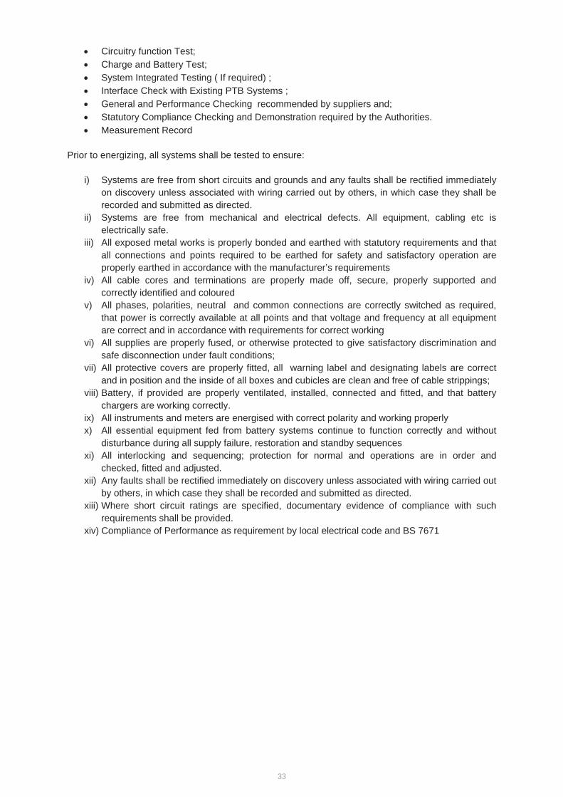
33
Circuitry function Test; Charge and Battery Test; System Integrated Testing ( If required) ; Interface Check with Existing PTB Systems ; General and Performance Checking recommended by suppliers and; Statutory Compliance Checking and Demonstration required by the Authorities. Measurement Record
Prior to energizing, all systems shall be tested to ensure:
i) Systems are free from short circuits and grounds and any faults shall be rectified immediately on discovery unless associated with wiring carried out by others, in which case they shall be recorded and submitted as directed.
ii) Systems are free from mechanical and electrical defects. All equipment, cabling etc is electrically safe.
iii) All exposed metal works is properly bonded and earthed with statutory requirements and that all connections and points required to be earthed for safety and satisfactory operation are properly earthed in accordance with the manufacturer’s requirements
iv) All cable cores and terminations are properly made off, secure, properly supported and correctly identified and coloured
v) All phases, polarities, neutral and common connections are correctly switched as required, that power is correctly available at all points and that voltage and frequency at all equipment are correct and in accordance with requirements for correct working
vi) All supplies are properly fused, or otherwise protected to give satisfactory discrimination and safe disconnection under fault conditions;
vii) All protective covers are properly fitted, all warning label and designating labels are correct and in position and the inside of all boxes and cubicles are clean and free of cable strippings;
viii) Battery, if provided are properly ventilated, installed, connected and fitted, and that battery chargers are working correctly.
ix) All instruments and meters are energised with correct polarity and working properly x) All essential equipment fed from battery systems continue to function correctly and without
disturbance during all supply failure, restoration and standby sequences xi) All interlocking and sequencing; protection for normal and operations are in order and
checked, fitted and adjusted. xii) Any faults shall be rectified immediately on discovery unless associated with wiring carried out
by others, in which case they shall be recorded and submitted as directed. xiii) Where short circuit ratings are specified, documentary evidence of compliance with such
requirements shall be provided. xiv) Compliance of Performance as requirement by local electrical code and BS 7671
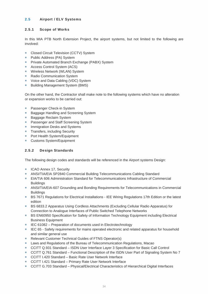
34
2.5 Airport / ELV Systems
2.5.1 Scope of Works
In this MIA PTB North Extension Project, the airport systems, but not limited to the following are involved:
Closed Circuit Television (CCTV) System Public Address (PA) System Private Automated Branch Exchange (PABX) System Access Control System (ACS) Wireless Network (WLAN) System Radio Communication System Voice and Data Cabling (VDC) System Building Management System (BMS)
On the other hand, the Contractor shall make note to the following systems which have no alteration or expansion works to be carried out:
Passenger Check-in System Baggage Handling and Screening System Baggage Reclaim System Passenger and Staff Screening System Immigration Desks and Systems Transfers, including Security Port Health System/Equipment Customs System/Equipment
2.5.2 Design Standards
The following design codes and standards will be referenced in the Airport systems Design:
ICAO Annex 17, Security ANSI/TIA/EIA SP2840 Commercial Building Telecommunications Cabling Standard EIA/TIA 606 Administration Standard for Telecommunications Infrastructure of Commercial BuildingsANSI/TIA/EIA-607 Grounding and Bonding Requirements for Telecommunications in Commercial BuildingsBS 7671 Regulations for Electrical Installations - IEE Wiring Regulations 17th Edition or the latest edition BS 6833.2 Apparatus Using Cordless Attachments (Excluding Cellular Radio Apparatus) for Connection to Analogue Interfaces of Public Switched Telephone Networks BS EN60950 Specification for Safety of Information Technology Equipment including Electrical Business Equipment IEC 61082 – Preparation of documents used in Electrotechnology IEC 65 - Safety requirements for mains operated electronic and related apparatus for household and similar general use Relevant Customer Technical Guides of FTNS Operator(s) Laws and Regulations of the Bureau of Telecommunication Regulations, Macao CCITT Q.931 Standard – ISDN User Interface Layer 3 Specification for Basic Call Control CCITT Q.761 Standard – Functional Description of the ISDN User Part of Signaling System No 7 CCITT I.420 Standard – Basic Rate User Network Interface CCITT I.421 Standard – Primary Rate User Network Interface CCITT G.703 Standard – Physical/Electrical Characteristics of Hierarchical Digital Interfaces
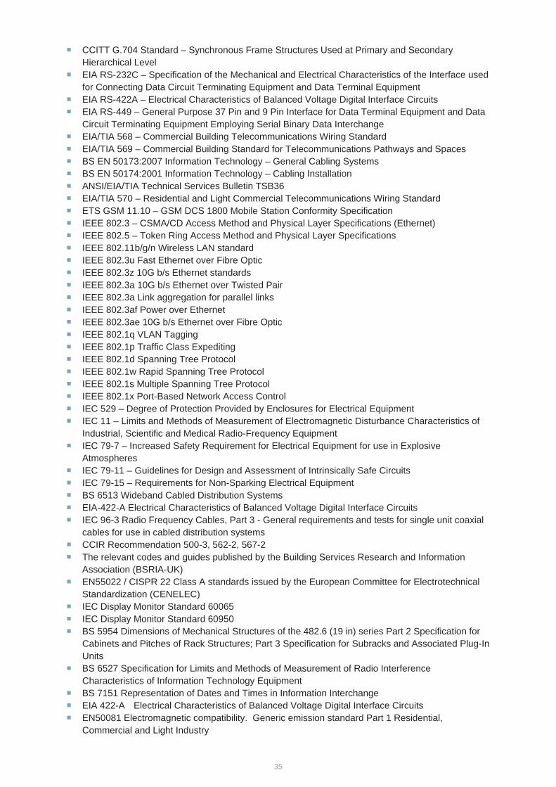
35
CCITT G.704 Standard – Synchronous Frame Structures Used at Primary and Secondary Hierarchical Level EIA RS-232C – Specification of the Mechanical and Electrical Characteristics of the Interface used for Connecting Data Circuit Terminating Equipment and Data Terminal Equipment EIA RS-422A – Electrical Characteristics of Balanced Voltage Digital Interface Circuits EIA RS-449 – General Purpose 37 Pin and 9 Pin Interface for Data Terminal Equipment and Data Circuit Terminating Equipment Employing Serial Binary Data Interchange EIA/TIA 568 – Commercial Building Telecommunications Wiring Standard EIA/TIA 569 – Commercial Building Standard for Telecommunications Pathways and Spaces BS EN 50173:2007 Information Technology – General Cabling Systems BS EN 50174:2001 Information Technology – Cabling Installation ANSI/EIA/TIA Technical Services Bulletin TSB36 EIA/TIA 570 – Residential and Light Commercial Telecommunications Wiring Standard ETS GSM 11.10 – GSM DCS 1800 Mobile Station Conformity Specification IEEE 802.3 – CSMA/CD Access Method and Physical Layer Specifications (Ethernet) IEEE 802.5 – Token Ring Access Method and Physical Layer Specifications IEEE 802.11b/g/n Wireless LAN standard IEEE 802.3u Fast Ethernet over Fibre Optic IEEE 802.3z 10G b/s Ethernet standards IEEE 802.3a 10G b/s Ethernet over Twisted Pair IEEE 802.3a Link aggregation for parallel links IEEE 802.3af Power over Ethernet IEEE 802.3ae 10G b/s Ethernet over Fibre Optic IEEE 802.1q VLAN Tagging IEEE 802.1p Traffic Class Expediting IEEE 802.1d Spanning Tree Protocol IEEE 802.1w Rapid Spanning Tree Protocol IEEE 802.1s Multiple Spanning Tree Protocol IEEE 802.1x Port-Based Network Access Control IEC 529 – Degree of Protection Provided by Enclosures for Electrical Equipment IEC 11 – Limits and Methods of Measurement of Electromagnetic Disturbance Characteristics of Industrial, Scientific and Medical Radio-Frequency Equipment IEC 79-7 – Increased Safety Requirement for Electrical Equipment for use in Explosive Atmospheres IEC 79-11 – Guidelines for Design and Assessment of Intrinsically Safe Circuits IEC 79-15 – Requirements for Non-Sparking Electrical Equipment BS 6513 Wideband Cabled Distribution Systems EIA-422-A Electrical Characteristics of Balanced Voltage Digital Interface Circuits IEC 96-3 Radio Frequency Cables, Part 3 - General requirements and tests for single unit coaxial cables for use in cabled distribution systems CCIR Recommendation 500-3, 562-2, 567-2 The relevant codes and guides published by the Building Services Research and Information Association (BSRIA-UK) EN55022 / CISPR 22 Class A standards issued by the European Committee for Electrotechnical Standardization (CENELEC) IEC Display Monitor Standard 60065 IEC Display Monitor Standard 60950 BS 5954 Dimensions of Mechanical Structures of the 482.6 (19 in) series Part 2 Specification for Cabinets and Pitches of Rack Structures; Part 3 Specification for Subracks and Associated Plug-In Units BS 6527 Specification for Limits and Methods of Measurement of Radio Interference Characteristics of Information Technology Equipment BS 7151 Representation of Dates and Times in Information Interchange EIA 422-A Electrical Characteristics of Balanced Voltage Digital Interface Circuits EN50081 Electromagnetic compatibility. Generic emission standard Part 1 Residential, Commercial and Light Industry

36
EN50082 Electromagnetic compatibility: Generic immunity standard Part 1 Residential, Commercial and Light Industry
ISO/IEC11801- Information technology –Generic cabling for customer premises ISO/IEC 24764 - Information technology -- Generic cabling systems for data centres TIA-942 - Telecommunications Infrastructure Standards for Data Centers
2.5.3 Particular Technical Requirements
This section of Particular Technical Requirements (PTR) specifies the particular technical and performance requirements for the extension of the existing Systems for the PTB North Extension Project in MIA.
Closed Circuit Television (CCTV) System
The Contractor shall be responsible for all the Works including but not limited to the CCTV system equipment design, supply, installation, testing and commissioning, documentation, training, and the interface co-ordination with the existing CCTV systemThe works shall include but not be limited to the provision of all necessary hardware and software as described in this PTR for the works. Such hardware shall include but not be limited to: a) Analogue and IP fixed and pan/tilt/zoom cameras, lens, housing and brackets. The camera
shall have at least 720p high definition video quality for general surveillance and 1080p high definition video quality for critical areas
b) Optical transceivers; c) Video distribution amplifiers; d) CCTV POE network switches such as CISCO 2960 series or equivalent; e) Digital Video Recorders (DVR) which shall record all 24x7 video images for 24-40 day
continuously but not more than 65 days.; f) Equipment enclosures, power supplies, optical transceivers with fibre cable organizers; g) Mounting brackets and poles; h) Surge arresters for all outdoor equipment installations; i) Fibre patch cord and horizontal fibre cables to and from cameras to new IDF Room(s) and
their termination and accessories; j) Coaxial cabling and coaxial patch cords, their termination and accessories; and k) All necessary local cable containment for the power and control cables required connected to
the main trunking.
The Works shall cover all areas within the Extension Building.
The Contractor shall carry out the design and installation of the mounting brackets/poles and necessary accessories, which shall be submitted for review without objection by the CAM Project Manager prior to manufacturing and installation.
All the proposed equipment shall be compatible with the existing CCTV system. Since the existing CCTV System is an analogue system under Pelco CM9760 System and shall be replaced soon, the Contractor shall take into account of the CCTV replacement works whereas IP Camera solution is the main approach for this project.
The Contractor shall be responsible for site survey on the existing equipment in order to have a basic knowledge on the design criteria and concept.
Alternative equipment proposed by the Contractor will be considered but shall be subject to review without objection by the CAM Project Manager.
The Contractor shall install, test and commission all the field devices as well as the CCTV equipment including cabinet(s) at the New IDF room in the PTB Extension. All the works after the network switch to the main CCTV System shall be carried out by others.
The Contractor shall provide documentation to the CAM Project Manager for review without objection. These shall include, but not be limited to, the following:
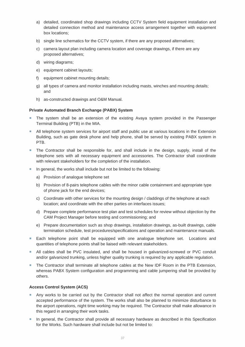
37
a) detailed, coordinated shop drawings including CCTV System field equipment installation and detailed connection method and maintenance access arrangement together with equipment box locations;
b) single line schematics for the CCTV system, if there are any proposed alternatives;
c) camera layout plan including camera location and coverage drawings, if there are any proposed alternatives;
d) wiring diagrams;
e) equipment cabinet layouts;
f) equipment cabinet mounting details;
g) all types of camera and monitor installation including masts, winches and mounting details; and
h) as-constructed drawings and O&M Manual.
Private Automated Branch Exchange (PABX) System
The system shall be an extension of the existing Avaya system provided in the Passenger Terminal Building (PTB) in the MIA.
All telephone system services for airport staff and public use at various locations in the Extension Building, such as gate desk phone and help phone, shall be served by existing PABX system in PTB.
The Contractor shall be responsible for, and shall include in the design, supply, install of the telephone sets with all necessary equipment and accessories. The Contractor shall coordinate with relevant stakeholders for the completion of the installation.
In general, the works shall include but not be limited to the following:
a) Provision of analogue telephone set
b) Provision of 8-pairs telephone cables with the minor cable containment and appropriate type of phone jack for the end devices;
c) Coordinate with other services for the mounting design / claddings of the telephone at each location; and coordinate with the other parties on interfaces issues;
d) Prepare complete performance test plan and test schedules for review without objection by the CAM Project Manager before testing and commissioning; and
e) Prepare documentation such as shop drawings, installation drawings, as-built drawings, cable termination schedule, test procedures/specifications and operation and maintenance manuals.
Each telephone point shall be equipped with one analogue telephone set. Locations and quantities of telephone points shall be liaised with relevant stakeholders.
All cables shall be PVC insulated, and shall be housed in galvanized-screwed or PVC conduit and/or galvanized trunking, unless higher quality trunking is required by any applicable regulation.
The Contractor shall terminate all telephone cables at the New IDF Room in the PTB Extension, whereas PABX System configuration and programming and cable jumpering shall be provided by others.
Access Control System (ACS)
Any works to be carried out by the Contractor shall not affect the normal operation and current accepted performance of the system. The works shall also be planned to minimize disturbance to the airport operations, night time working may be required. The Contractor shall make allowance in this regard in arranging their work tasks.
In general, the Contractor shall provide all necessary hardware as described in this Specification for the Works. Such hardware shall include but not be limited to:
38
a) a) Door Controller with 2 hours UPS Backup facilitiesPeripheral access control devices such as card readers (i.e. Honeywell DR4205 reader), integrated card reader with PIN Pad (i.e. Honeywell DR4205K reader with PIN pad), door release button, biased magnetic sensors, breakglasses, and the like, including all interconnections, field equipment cabling, and cabling back to the associated Controller(s) (i.e. Honeywell PW-Series) located at new IDF room in PTB Extension.
Design, supply and installation of the card readers, Controller(s) and the related ACS equipment components, mounting brackets and necessary accessories which shall be subject to review without objection by the CAM Project Manager prior to manufacturing and installation;
Provision of all containment as required for the connection to the final field equipment devices. This shall include but not be limited to cable trunking, trays, cable ladders, concealed conduits, back boxes, termination boxes, flexible conduits, etc. All such last-run connections in conduits shall be concealed unless otherwise specified.
The existing ACS System have interfaced with the fire services system by means of the electromagnetic (EM) door lock. The Contractor shall study the existing arrangement and implement the same arrangement at the new EM door locks into the new PTB Extension.
All the proposed equipment shall be compatible with the existing Access Control System in MIA.
Modification of existing system shall be carried out by others.The Contractor shall provide documentation to the CAM Project Manager for review without objection. These shall include but not be limited to the following:
a) detailed, coordinated shop drawings including ACS System field equipment installation, detailed connection method, maintenance access arrangement together with equipment box locations;
b) single line schematics for the ACS system;
c) access control type connection and installation diagrams;
d) wiring diagrams;
e) equipment cabinet layouts;
f) equipment cabinet mounting details;
g) O&M manuals; and
h) as-constructed Record Drawings.
Wireless Network (WLAN) System
Any works to be carried out by the Contractor shall not affect the normal operation and current accepted performance of the system. The works shall also be planned to minimize disturbance to the airport operations, night time working may be required. The Contractor shall make allowance in this regard in arranging their work tasks.
The Contractor shall design, develop, construct, programme, configure, engineer, supply, deliver, install, set up, test and commission the system works as hereunder described, Specifications, and any works not specifically mentioned but required to complete the Works.
The system is a flexible data communications system implemented as an extension to the existing airport wide Wireless LAN system. Using radio frequency (RF) technology, the system transmits and receives data over the air, minimizing the need for wired connections.
The system standard to be used shall be based on IEEE 802.11b (Wi-Fi) standard and also IEEE 802.11a/g. The existing Wireless LAN installed in the airport is based on IEEE 802.11b standard but shall also support the IEEE 802.11g standard.
The quantities and locations of Access Points shall be restricted by the available ports at POE edge switches and licenses on the wireless controllers.. The Contractor shall evaluate the coverage based on the particular equipment to be provided, and develop the layout in details with

39
coordination among other related services including architectural and electrical. The Contractor shall submit, for review without objection by the CAM Project Manager, the equipment details and locations to demonstrate the required coverage and performance can be met before implementation.
The Contractor shall undertake detailed site survey and signal strength measurements for the review without objection by the CAM Project Manager, to confirm the final quantities and locations of the Access Points to achieve or ensure acceptable signal coverage in the areas required.
The Contractor shall provide all necessary horizontal cabling from the New IDF Room to all the Access Points and a POE Network Switch (i.e CISCO 2960 or equivalent) shall also be provided. All upstream cabling works shall be under the scope of voice and data cabling works. Regarding the Wireless LAN System configuration, it shall be done by others.
In general, the works shall include but not be limited to the following:
a) Provision of all necessary hardware and software;
b) Design and develop equipment mounting brackets/poles and necessary accessories, which shall be subject to review without objection by the CAM Project Manager prior to manufacturing and installation;
c) Provision of cables with the minor cable containment for the end devices.
d) Coordinate with other services for the mounting design / claddings of each location;
e) Prepare complete performance test plan and test schedules for review without objection by the CAM Project Manager before testing and commissioning; and
f) Prepare documentation such as shop drawings, installation drawings, as-built drawings, test procedures/specifications and operation and maintenance manuals.
Modification of existing systems shall be carried out by others.Radio Communication System
Any works to be carried out by the Contractor shall not affect the normal operation and current accepted performance of the system. The works shall also be planned to minimize disturbance to the airport operations, night time working may be required. The Contractor shall make allowance in this regard in arranging their work tasks.
The Contractor shall design, develop, construct, programme, configure, engineer, supply, deliver, install, set up, test and commission the system works as hereunder described, Specifications, and any works not specifically mentioned but required to complete the Works.
The Contractor shall base on the existing signal source to design and develop the antenna network at the PTB Extension and all associated radio communication equipment shall be supplied and installed at the new IDA Room. The antenna network shall provide RF coverage throughout the entire Extension Building operating area.
In general, the works shall include but not be limited to the following:
a) provision of all necessary hardware as described for the works. Alternative equipment proposed by the Contractor will be considered and shall obtain review without objection by the CAM Project Manager;
b) all the proposed equipment shall be compatible with the existing radio communication system installed in PTB;
c) the design and configurations of the mounting brackets/poles and necessary accessories shall be reviewed without objection by the CAM Project Manager prior to manufacturing and installation;
d) provision of all necessary local cable containment for the power and control cables required;
e) provision of all cables and associated cabling / termination work; and
40
f) The Contractor shall provide the documentation including equipment submission (with equipment specification), signal strength calculation (i.e. link budget calculation), design / calculation on coverage prediction / analysis, antenna mounting design drawings, installation drawings and etc. to obtain review without objection by the CAM Project Manager.
g) The modification works on the existing system shall be carried out by others
Voice and Data Cabling (VDC) System
The voice and data cabling infrastructure design in the Extension Project shall be modelled on the existing voice and data cabling arrangement in MIA.
Any works to be carried out by the Contractor shall not affect the normal operation and current accepted performance of the system. The works shall also be planned to minimize disturbance to the airport operations.
In order to maintain continuous services and not to disrupt the normal operation of the airport terminal, night time working shall be required for certain works which would cause downtime of the affected system and affect the normal operation of the system. The Contractor shall make allowance in this regard in arranging their work tasks.
All outdoor cables for both copper and fibre cables, e.g. passing through external ducts, if any, shall be armour-type cables suitable for external outdoor use. No direct buried cable installation shall be allowed.
All voice and data cabling outlets, fibre and copper termination frames, media converters, junction boxes, termination boxes, faceplates, etc. which are installed in exposed outdoor environment shall be provided with suitable weather-proof housing by the Contractor with a minimum standard of IP65 rating.
The Contractor shall develop, construct, programme, supply, deliver, install, set up, test and commission the system works as hereunder described, as well as any works not specifically mentioned but required to complete the works.
In view of the PTB extension containing an area of about 3600 sq.m, The Contractor shall construct extra new IDF room(s) which would take care all various signalling service and networking provision in this new extension.
The design and implementation of new IDF Room(s), shall follow the local code, international standard and industry requirement such as ISO/IEC 11801, ISO/IEC 24764, TIA-942, etc. Where there is a difference or conflict between such international standard and in the Macau local codes, Macau local codes shall prevail.
The structure cabling system in the new PTB extension shall not be separated from the existing structure cabling system. The design shall connect or integrate the new system into the existing system to form a complete System in order to allow a smooth and effective operation in the PTB including its new extension, or even to other buildings within MIA.
The scope of works of the Contract includes the following as a minimum:
a) All cabling for airport systems including all fibre and copper cables carrying voice, data or multimedia traffic;
b) Supply, installation, testing and commissioning of cabling components including but not be limited to the following components as a minimum:
c) Multipair / UTP / STP copper cables;
d) Single mode / Multimode fibre cables;
e) Patch panels and patch cords;
f) Termination frames including mounting frames, termination blocks and cable management modules for the termination frames;
g) Data / voice / fibre socket outlets and faceplates;
41
h) Equipment cabinets in new IDF Room and/or closets
i) Equipment cabinet accessories such as cable management rings, channels, wiring managers, in-cabinet containments, ventilation fans, equipment shelves, raised floor tile grommets, floor-cut-outs, etc;
j) All copper, coaxial and fibre cable connectors;
k) Termination boxes and back boxes;
l) Cross connecting cables for the jumpering of voice and data connections across frame verticals;
m) Cable labelling, numbering and marker for all cables, patch panels, equipment racks, frames, outlets, patch cords, etc; in particular, all the external cables shall be labelled properly in each drawpit at cable entry and exit points;
n) Final connections (jumpering / patching) from the new VDC infrastructure to the existing infrastructure to connect necessary circuits;
o) All other relevant accessories and sundry items required for the complete operation of the VDC system; and
h) All cabling provisions shall be low smoke and fume (LSF/LSOH) type and shall apply to optic fibre and Cat 5e or Cat 6 UTP cables.
i) Voice and Data Outlets (VDO) and Distribution Frames in all locations shall be marked on the Contractor’s Design Drawings.
j) Allocation and recording of the cable utilization records and coordination of the utilization cable space and positioning in risers, cable trays, cable ducts, etc, to ensure efficient and neat utilization of commonly used cable routes. This shall include but not be limited to BMS, ACS, CCTV, WLAN, FIDS, PA, MATV, PABX, etc;
k) Installation of associated necessary items such as secondary cable containment such as cable tray, conduit, trunking and other such items will be required to connect to the backbone tray and trunking scheme;
l) Contractor's Drawings (shop drawings, design calculations, etc);
m) As-built Record Drawings with the indication of cable length and cable paths from the VDOs to the distribution frame;
n) Testing and commissioning of all system components; and
o) Opertion and Maintenance Manual
Please find Appendix 1 for the existing VDC Structure Cabling Route for your reference.
Public Address (PA) System
Any works to be carried out by the Contractor shall not affect the normal operation and current accepted performance of the system. The works shall also be planned to minimize disturbance to the airport operations, night time working may be required. The Contractor shall make allowance in this regard in arranging their work tasks.
The PA system provided at the PTB Extension shall be an extension of the existing Bosch Digital PA System and be fully operated within the PTB Extension both in system control and management.
42
The Contractor shall include the engineering, design, development, construction, supply, delivery, installation, fabrication, assembly, , installation set up, testing and commissioning, documentation, training and warranty of the PA System.
Should there be any modification, reconfiguration, addition of Public Address devices, the overall system performance of the existing PA system shall not be degraded in any form and be carried out by others
The Contractor shall obtain sufficient information from the supplier or maintenance contractor or even site inspection of the existing PA system to formulate the design criteria and concept and to ensure a smooth integration/changeover to the extended PA system in PTB Extension without service interruption.
The Contractor shall base on their design to install the PA System equipment at the new IDA Room(s) and provide associated cabling works for the field PA Speakers. Suitable quantity of PA system equipment cabinet(s) shall be supplied and installed by the Contractor.
In general, the works shall include but not be limited to the following:
a) Provide all system engineering and design necessary to develop the complete systems such as system schematics, hardward drawings, system diagrams, schedules and lists;
b) Provision of all necessary hardware
c) Provide design, supply, install and configuration of the mounting brackets/poles and necessary accessories, which shall be subject to review without objection by the CAM Project Manager prior to manufacturing and installation;
d) Provision of all necessary local cable containment for the power and control cables required;
e) Submit a detailed changeover plan with necessary fallback/contingency plans for review without objection by CAM Project Manager.
f) The modification works on existing system shall be carried out by others.
Building Management System (BMS)
The Contractor shall supply, install, configure, test and commissioning the BMS installation, including provision of all necessary hardware, software and associate software license, testing at the manufacturer's works, delivery to Site, interfacing work for other services, certificates and guarantees.
Should there be any modification, reconfiguration, addition of BMS devices, the overall system performance in the existing BMS system shall not be degraded in any form or causing implication to the operations of the existing BMS system;
The Contractor shall include and provide all interface components for BMS, including dry contacts, relay, high level interface, cables, trunking, conduits and local I/O panel etc. to interface with the Building Services (BS) / Electrical & Mechanical (E&M) equipment;
The Contractor shall be responsible for the completion of Building Management System (BMS) as specified including but not be limited to the following:
a) Supply and install the complete communication networks which consist but not be limited to optical fibre cables, Cat 5e copper cables, network switches, optical fibre transceiver and receiver and routers. The BMS shall be interfaced to the existing BMS system. The Contractor shall provide all the hardware and software for transmitting and receiving BMS signals to and from the PTB.
b) Supply and install of all necessary cables and cable containment facilities (trunkings, conduits etc.) for the complete system installation.
c) Supply and install all necessary field control cabling and containment systems for cables run between the I/O panels and monitoring/controlling devices;
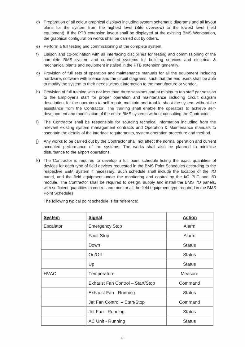
43
d) Preparation of all colour graphical displays including system schematic diagrams and all layout plans for the system from the highest level (Site overview) to the lowest level (field equipment). If the PTB extension layout shall be displayed at the existing BMS Workstation, the graphical configuration works shall be carried out by others.
e) Perform a full testing and commissioning of the complete system.
f) Liaison and co-ordination with all interfacing disciplines for testing and commissioning of the complete BMS system and connected systems for building services and electrical & mechanical plants and equipment installed in the PTB extension generally.
g) Provision of full sets of operation and maintenance manuals for all the equipment including hardware, software with licence and the circuit diagrams, such that the end users shall be able to modify the system to their needs without interaction to the manufacture or vendor.
h) Provision of full training with not less than three sessions and at minimum ten staff per session to the Employer’s staff for proper operation and maintenance including circuit diagram description, for the operators to self repair, maintain and trouble shoot the system without the assistance from the Contractor. The training shall enable the operators to achieve self-development and modification of the entire BMS systems without consulting the Contractor.
i) The Contractor shall be responsible for sourcing technical information including from the relevant existing system management contracts and Operation & Maintenance manuals to ascertain the details of the interface requirements, system operation procedure and method.
j) Any works to be carried out by the Contractor shall not affect the normal operation and current accepted performance of the systems. The works shall also be planned to minimise disturbance to the airport operations.
k) The Contractor is required to develop a full point schedule listing the exact quantities of devices for each type of field devices requested in the BMS Point Schedules according to the respective E&M System if necessary. Such schedule shall include the location of the I/O panel, and the field equipment under the monitoring and control by the I/O PLC and I/O module. The Contractor shall be required to design, supply and install the BMS I/O panels, with sufficient quantities to control and monitor all the field equipment type required in the BMS Point Schedules;
The following typical point schedule is for reference:
System Signal Action
Escalator Emergency Stop Alarm
Fault Stop Alarm
Down Status
On/Off Status
Up Status
HVAC Temperature Measure
Exhaust Fan Control – Start/Stop Command
Exhaust Fan - Running Status
Jet Fan Control – Start/Stop Command
Jet Fan - Running Status
AC Unit - Running Status
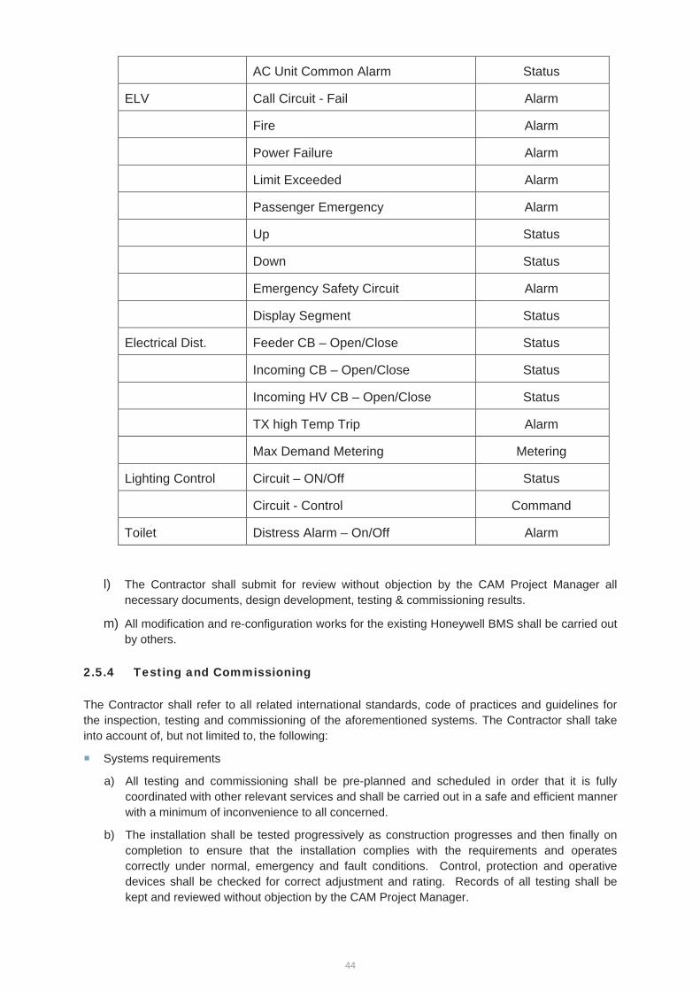
44
AC Unit Common Alarm Status
ELV Call Circuit - Fail Alarm
Fire Alarm
Power Failure Alarm
Limit Exceeded Alarm
Passenger Emergency Alarm
Up Status
Down Status
Emergency Safety Circuit Alarm
Display Segment Status
Electrical Dist. Feeder CB – Open/Close Status
Incoming CB – Open/Close Status
Incoming HV CB – Open/Close Status
TX high Temp Trip Alarm
Max Demand Metering Metering
Lighting Control Circuit – ON/Off Status
Circuit - Control Command
Toilet Distress Alarm – On/Off Alarm
l) The Contractor shall submit for review without objection by the CAM Project Manager all necessary documents, design development, testing & commissioning results.
m) All modification and re-configuration works for the existing Honeywell BMS shall be carried out by others.
2.5.4 Testing and Commissioning
The Contractor shall refer to all related international standards, code of practices and guidelines for the inspection, testing and commissioning of the aforementioned systems. The Contractor shall take into account of, but not limited to, the following:
Systems requirements
a) All testing and commissioning shall be pre-planned and scheduled in order that it is fully coordinated with other relevant services and shall be carried out in a safe and efficient manner with a minimum of inconvenience to all concerned.
b) The installation shall be tested progressively as construction progresses and then finally on completion to ensure that the installation complies with the requirements and operates correctly under normal, emergency and fault conditions. Control, protection and operative devices shall be checked for correct adjustment and rating. Records of all testing shall be kept and reviewed without objection by the CAM Project Manager.

45
c) All equipment or materials found to be faulty during testing shall either be replaced or repaired free of charge.
For cable testing, the Contractor shall:
a) Test all point to point wiring, where applicable.
b) Provide documentary evidence of all cable test results of point to point wiring installation.
c) Report the extent of any failures identified during testing which may affect the installation programme.
d) Correct any wiring faults discovered during the testing and commissioning at no additional cost to the Contract.
The Contractor shall also note:
a) The installation shall be thoroughly tested by the Contractor so as to ensure every point and item of plant is being controlled and/or monitored correctly.
b) The Contractor shall carry out all of the tests and any other tests required by the CAM Project Manager to demonstrate that the complete system is fully operational and satisfactory, and in accordance with the requirements of the PTS. The Contractor shall provide all equipment and personnel required for the testing and commissioning.
c) In the event of any test indicating failure to comply, that test and those proceeding tests, the results of which may have been influenced by the fault indicated, shall be repeated after the fault has been rectified.
d) If failure to provide the required and reliable coverage for the Extension Building areas, the Contractor shall be responsible for modifying the proposed design to achieve the required standard and specification at no additional cost.
e) It is a requirement that the system is tested and commissioned by personnel who have gained an intimate understanding of the project throughout its design stages. These personnel must also have had at least five years of experience in the related field. Should any commissioning personnel not meet these requirements the Contractor shall apply and shall obtain review without objection by the CAM Project Manager prior to allowing the said commissioning persons on site.
f) The Contractor shall submit the testing and commissioning details for the review without objection by the CAM Project Manager before implementation.
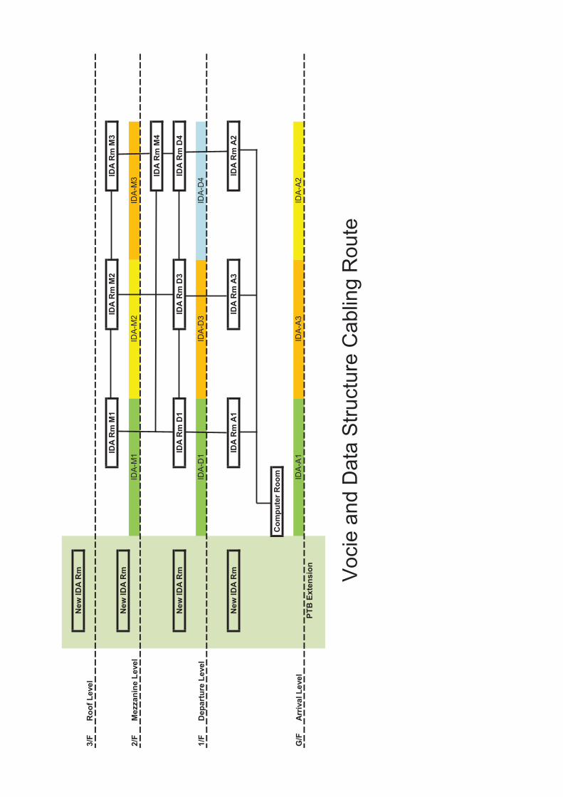
New
IDA
Rm
3/F
Roo
f Lev
el
IDA
Rm
M1
IDA
Rm
M2
IDA
Rm
M3
New
IDA
Rm
2/F
Mez
zani
ne L
evel
IDA
Rm
M4
New
IDA
Rm
IDA
Rm
D1
IDA
Rm
D3
IDA
Rm
D4
1/F
Dep
artu
re L
evel
New
IDA
Rm
IDA
Rm
A1
IDA
Rm
A3
IDA
Rm
A2
Com
pute
r Roo
m
G/F
Arr
ival
Lev
elPT
B E
xten
sion
IDA
-A2
IDA
-A3
IDA
-A1
Voc
ie a
nd D
ata
Stru
ctur
e C
ablin
g R
oute
IDA
-M1
IDA
-D1
IDA
-M2
IDA
-D3
IDA
-M3
IDA
-D4
Specification for Finishes and Facade
Finishes
The type of finishes to be used shall be to the architectural drawing. Specifications for screed and rigidtile/slab finishes are listed as follows:
Screed Finishes
Aggregate for lightweight screeds shall be as follows:
i) 5mm exfoliated vermiculite to BS3797ii) Approved proprietary lightweight beads or granules
Air entraining agent for lightweight screed shall be an approved admixture which will produce screedswith a dry density not more than 1200kg/m2. Vapour barrier shall be 0.08mm polythene sheet.
Floor screeds generally shall be in accordance with CP204:Pt.2 and BS8000L Pts 11.19 and wall screedsto BS5385:Pt 1 and BS 8000:PT 11.1 respectively.
Screeds generally shall consist of cement and sand 1:3. Use the minimum water consistent withworkability.
For floor screeds over 40mm thick, mix shall be 1 part cement, 1.5 pars sand or granite fines and 3 partscoarse aggregate graded 10mm down with at 75% being retained on a 5mm B.S. sieve.
Use granite fines instead of sand when required to avoid efflorescence on the surface of the finish.
Thickness of wall render shall be 10mm (minimum ) with surface scratched to form key.
Thickness of floor screeds shall be as follows:
i) Laid monolithically with base : 15mm (minimum) thick. (for preparation of base, see Clause18.17)
ii) Bonded to a hardened concrete base: 20mm (minimum) thick. (For preparation of base, seeClause 18.16(.
iii) Not bonded to the base: 50mm (minimum) thick including tile finish.
iv) Floating: 65mm (minimum) thick including tile finish
Lay screeds in bays of 15 sq. m (maximum) with length not more than 1.5 times the width inchequerboard pattern. Allow 24 hours(minimum) between laying adjoining bays.
Lightweight aggregate screeds shall consist of cement and lightweight aggregate 1:8 for roofs and 1:6for floors unless contrary to the manufacturer’s recommendations.
Lightweight screeds shall be 50mm (minimum) thick, excluding topping.
Finish lightweight screeds with cement and sand or granite fines 1:4 topping 15mm (minimum) thick laidmonolithically with the screed.
When specified lay vapour barrier under lightweight roof screeds.
The surface of screeds shall be finished with one of the following surface finishes, levels, to falls asspecified:
(i) Steel trowel or power float to give a smooth untextured surface.
(ii) Wood float to give an even textured surface.
(iii) Stiff brush to give a slightly roughened texture
Rigid Tile or Slab Finishes
Submit samples of tile, and obtain approval.
Plain concrete or granolithic concrete floor tiles shall be BS 1119:Pt 2, of the required colour and surfacefinish.
Ceramic floor tiles including corresponding accessories shall be to BS 6431. Ceramic floor tiles shall beGroup A I or BI: water absorption not exceeding 3%.
Floor quarries shall be Group A IIb of BS6431: water absorption of 6% < E =<10%.
Where ceramic floor tiles or clay floor quarries are described as “including specials” the full range of BSfitting shall be required. Elsewhere mitred angles of covered skirtings and the like shall be permitted.
All tiles and fitting shall be from the same manufacturer and shall match in colour and mixture.
Where tiles are described as anti slip, they shall be suitably embossed or treated with carborundum orsimilar grit to comply with relevant standards.
Terrazzo floor ties shall be to BS 4131 and of the required colour and surface finish.
Concrete roofing tiles and fitting shall be to BS EN 490 and BS EN491.
The tiles shall be flat tiles 30mm thick and 300mm square or 35mm thick and 400mm square.
Insulating roofing tiles shall be 40mm thick and 30mm square or 40mm square with at a density of 1250kg/m3. The upper surface shall be hard and suitable for pedestrian traffic. Five legged tiles shall not bepermitted.
Glazed ceramic wall tiles shall be to BS6431 and in Group A IIa or B IIa with a water absorption notexceeding 6%.
Tiles shall be glazed, white or coloured as required and with cushion edge and with inclusive spacer lugsas required.
External facing tiles shall be of the specified type from an approved manufacturer.
Stone slabs for paving or wall facings or fittings shall be of the quality and colours specified on drawingsor as selected and free from flaws and defects throughout. Unless otherwise specified, slabs for wallfacing shall not be less than 20mm thick and slabs for paving surfaces shall not be less than 32mm thick.
Stones shall be jointed so as to be dressed to match stone by stone.
Precast concrete paving blocks shall be to BS 6717: Pts 1 & 3 and of the size, colour and surface texturedspecified.
Adhesive for tiles or mosaics shall be compatible with background and finish and shall be an approvedproprietary brand.
Facade
The façade for the building should be designed to the architecture’s intent.
Glass generally shall be to BS 952.
Clear sheet glass shall be drawn of ordinary quality for glazing.
Translucent glass shall be cast or figure rolled of the type and quality required.
Obscured glass shall have the required degree of obscuration and diffusion.
Wired cast glass and wired polished glass shall have a square mesh wire 13mm square electricallywelded at each intersection.
Mirror glass shall be selected float suitable for silvering.
Heat strengthened glass shall be glass that has been treated to approximately double the strength andimpact resistance of untreated glass but not to the requirements of safety glass.
Fully tempered glass shall be glass that has been heat treated to approximately four times the strengthand impact resistance of untreated glass and upon fracture would break into small fragments.
Tinted glass shall be body tinted of the colour and intensity specified.
Reflective glass shall be an approved proprietary product with a reflective coating on the designatedsurface to the colour and performance specified.
Laminated glass shall be an approved proprietary product comprising two or more sheets bondedtogether and incorporating a plastic interlayer to ensure the performance specified.
Keep glass and plastic dry and clean during delivery and store vertically in a well vented locationcarefully protected from condensation and other moisture. There shall be air between stored glasssheets.


![Ch.5 Conceptual Design Process. - IEMS. Conceptual Design Process.pdf · - 4 - ■ Conceptual Design. [Blanchard, pp123 - 150] Conceptual Design Process. ․ Needs Analysis and Identification](https://img.pdfslide.net/doc/110x75/5a7a012d7f8b9a3d058c8530/ch5-conceptual-design-process-conceptual-design-processpdf-4-conceptual.jpg)