Embed Size (px)
Citation preview
SECTOR II traffic barrier Installation manual
Centurion Systems (Pty) Ltd www.centsys.com
After-sales multi-languageTechnical Support
Monday to Fridayfrom 07h00 to 18h00UTC+2Saturdays 08h00 to 16h30 UTC +2
Manufactures tointernational
quality standardISO 9001:2008
100% testing of products
In-houseR&Ddevelopmentteam
Centurion Systems (Pty) Ltd reserves the right to make changes to the products described in this manual without notice and without obligation to notify any persons of any such revisions or changes. Additionally, Centurion Systems (Pty) Ltd makes no representations or warranties with respect to this manual. No part of this document may be copied, stored in a retrieval system or transmitted in any form or by any means electronic, mechanical, optical or photographic, without the express prior written consent of Centurion Systems (Pty) Ltd.
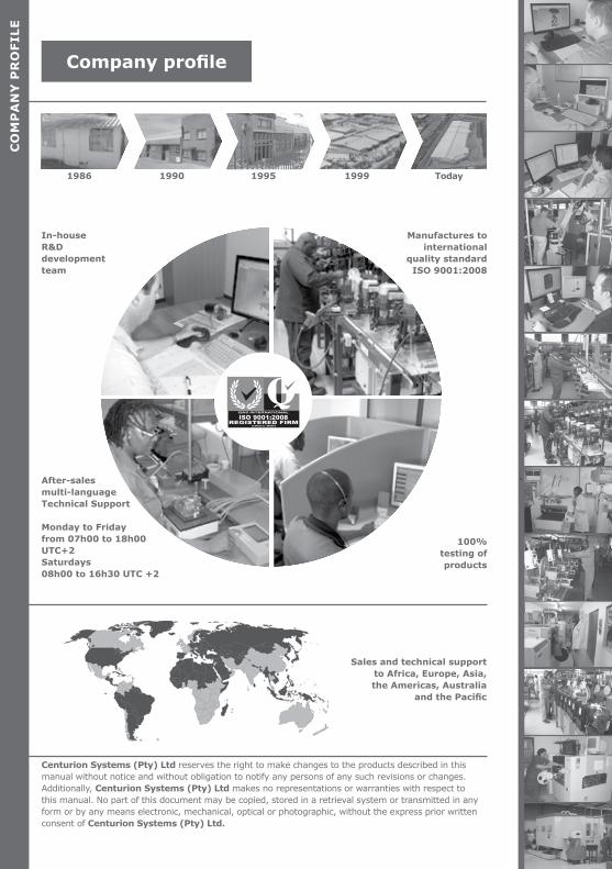
1986 1990 1995 1999 Today
CO
MP
AN
Y P
RO
FILE
Company profile
Sales and technical support to Africa, Europe, Asia, the Americas, Australia
and the Pacific
page 3www.centsys.com
SAFETYFIRST IMPORTANT SAFETY INSTRUCTIONS
1. Glossary of terms
2. Product identification
2.1 Internal components
2.2 External components
2.3 Electronics tray
2.4 Hardware unpacking
3. Physical installation
3.1 Preparation of the cabinet plinth
3.2 Mounting the cabinet
3.3 Fitting and levelling the boom pole
4. Onsite electrical wiring
4.1 AC and DC power isolation
4.2 Earthing the unit
4.3 Wiring AC power to the SECTOR II Traffic Barrier
4.4 Installing loop detectors
4.4.1 Installing a single FLUX SA loop detector
4.4.2 Installing dual FLUX SA loop detectors
5. Basic controller setup
5.1 Powering up the SECTOR II
5.2 Programming the controller
6. Installation handover
7. Advanced controller setup
7.1 Menu navigation map
Installation flow diagram: Center-fold pull-out
8. Maintenance
9. Troubleshooting
9.1 Diagnostics
page 7
page 8
page 8
page 9
page 9
page 10
page 11
page 11
page 12
page 14
page 17
page 17
page 18
page 18
page 19
page 19
page 21
page 23
page 23
page 23
page 27
page 29
page 30
page 39
page 47
page 48
page 48
Contents
CO
NT
EN
TS
page 5
page 4 www.centsys.com
10. Appendices
10.1 SECTOR II specifications
10.1.1 Unit specifications
10.1.2 Barrier boom pole specifications
10.1.3 Fuse protection
10.1.4 Certificate of compliance
10.2. Changing the SECTOR II to a left-hand configuration
10.3 Adjusting limits for Fail-safe Mode
10.4 11-pin loop detector installations
10.4.1 Installing a single FLUX 11-pin loop detector
10.4.2 Installing dual FLUX 11-pin loop detectors
10.5 Safety beam installation
10.6 Wiring diagrams for installation modes
10.6.1 Simplex Mode
10.6.2 Complex Mode (Option 1)
10.6.3 Complex Mode (Option 2 - Ticket vendors)
10.6.4 Uni-directional traffic
10.6.5 Bi-directional traffic
10.7 Factory Default Settings (South Africa only)
10.8 Terminal descriptions
10.9 Ancillary installation equipment
Icons used in this manual
page 51
page 51
page 49
page 52
page 52
page 53
page 54
page 60
page 61
page 63
page 65
page 67
page 68
page 68
page 69
page 70
page 71
page 71
page 72
page 74
page 76
CO
NT
EN
TS
This icon indicates tips and other information that could be useful during the installation.
This icon denotes variations and other aspects that should be considered during installation.
This icon indicates warning, caution or attention! Please take special note of critical aspects that MUST be adhered to in order to prevent injury.
This icon indicates areas where mechanical crushing may occur
page 5www.centsys.com
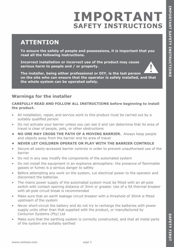
ATTENTIONTo ensure the safety of people and possessions, it is important that you read all the following instructions.
Incorrect installation or incorrect use of the product may cause serious harm to people and / or property.
The installer, being either professional or DIY, is the last person on the site who can ensure that the operator is safely installed, and that the whole system can be operated safely.
IMPORTANT SAFETY INSTRUCTIONS
Warnings for the installer CAREFULLY READ AND FOLLOW ALL INSTRUCTIONS before beginning to install the product.
• All installation, repair, and service work to this product must be carried out by a suitably qualified person
• Do not activate your barrier unless you can see it and can determine that its area of travel is clear of people, pets, or other obstructions
• NO ONE MAY CROSS THE PATH OF A MOVING BARRIER. Always keep people and objects away from the barrier and its area of travel
• NEVER LET CHILDREN OPERATE OR PLAY WITH THE BARRIER CONTROLS• Secure all easily-accessed barrier controls in order to prevent unauthorised use of the
barrier• Do not in any way modify the components of the automated system• Do not install the equipment in an explosive atmosphere: the presence of flammable
gasses or fumes is a serious danger to safety• Before attempting any work on the system, cut electrical power to the operator and
disconnect the batteries• The mains power supply of the automated system must be fitted with an all-pole
switch with contact opening distance of 3mm or greater. Use of a 5A thermal breaker with all-pole circuit break is recommended
• Make sure that an earth leakage circuit breaker with a threshold of 30mA is fitted upstream of the system
• Never short-circuit the battery and do not try to recharge the batteries with power supply units other than that supplied with the product, or manufactured by Centurion Systems (Pty) Ltd
• Make sure that the earthing system is correctly constructed, and that all metal parts of the system are suitably earthed
IMP
OR
TA
NT
SA
FET
Y IN
ST
RU
CT
ION
SS
AFE
TY
FIRS
T

page 6 www.centsys.com
• Safety devices must be fitted to the installation to guard against mechanical movement risks, such as crushing, dragging and shearing
• It is recommended that at least one warning indicator light be fitted to every system• Always fit the warning signs visibly to the inside and outside of the barrier• The installer must explain and demonstrate the manual operation of the barrier in
case of an emergency, and must hand over the user guide to the user• Explain these safety instructions to all persons authorised to use this barrier, and be
sure that they understand the hazards associated with traffic barriers• Do not leave packing materials (plastic, polystyrene, etc.) within reach of children as
such materials are potential sources of danger• Dispose of all waste products like packing materials, worn-out batteries, etc.
according to local regulations• Always check the obstruction detection system and safety devices for correct
operation• Neither Centurion Systems (Pty) Ltd, nor its subsidiaries, accepts any liability caused
by improper use of the product, or for use other than that for which the automated system was intended
• This product was designed and built strictly for the use indicated in this documentation. Any other use, not expressly indicated here, could compromise the service life/operation of the product and/or be a source of danger
• Anything that has not been specified in these instructions may be considered a risk to your safety, and the safety of others. If you are unsure of an installation matter, please contact your nearest distributor
SA
FET
Y F
IRS
TIM
PO
RT
AN
T S
AFE
TY
IN
ST
RU
CT
ION
S
page 7www.centsys.com
GLO
SS
AR
Y O
F TE
RM
SS
EC
TIO
N 1
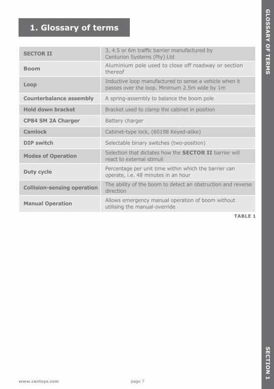
1. Glossary of terms
SECTOR II 3, 4.5 or 6m traffic barrier manufactured by Centurion Systems (Pty) Ltd
Boom Aluminium pole used to close off roadway or section thereof
Loop Inductive loop manufactured to sense a vehicle when it passes over the loop. Minimum 2.5m wide by 1m
Counterbalance assembly A spring-assembly to balance the boom pole
Hold down bracket Bracket used to clamp the cabinet in position
CP84 SM 2A Charger Battery charger
Camlock Cabinet-type lock, (60198 Keyed-alike)
DIP switch Selectable binary switches (two-position)
Modes of Operation Selection that dictates how the SECTOR II barrier will react to external stimuli
Duty cycle Percentage per unit time within which the barrier can operate, i.e. 48 minutes in an hour
Collision-sensing operation The ability of the boom to detect an obstruction and reverse direction
Manual Operation Allows emergency manual operation of boom without utilising the manual-override
TABLE 1
page 8 www.centsys.com
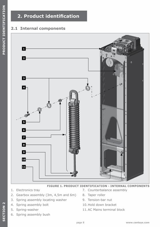
1. Electronics tray2. Gearbox assembly (3m, 4,5m and 6m)3. Spring assembly locating washer4. Spring assembly bolt5. Spring-washer6. Spring assembly bush
7. Counterbalance assembly8. Taper roller9. Tension-bar nut10. Hold down bracket11. AC Mains terminal block
2. Product identification
FIGURE 1. PRODUCT IDENTIFICATION - INTERNAL COMPONENTS
5
6
4
1
2
3
8
9
10
11
2.1 Internal components
7
PR
OD
UC
T I
DE
NT
IFIC
AT
ION
SE
CT
ION
2
page 9www.centsys.com
SE
CT
ION
2P
RO
DU
CT
IDE
NT
IFICA
TIO
N
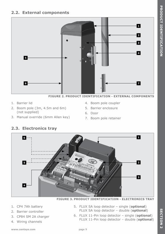
1. Barrier lid2. Boom pole (3m, 4.5m and 6m)
(not supplied)3. Manual override (6mm Allen key)
4. Boom pole coupler5. Barrier enclosure6. Door 7. Boom pole retainer
1. CP4 7Ah battery2. Barrier controller3. CP84 SM 2A charger4. Wiring channels
5. FLUX SA loop detector – single (optional) FLUX SA loop detector – double (optional)
6. FLUX 11-Pin loop detector – single (optional) FLUX 11-Pin loop detector – double (optional)
FIGURE 2. PRODUCT IDENTIFICATION - EXTERNAL COMPONENTS
FIGURE 3. PRODUCT IDENTIFICATION - ELECTRONICS TRAY
76
5
5
4
6
2
2
4
3
3
1
1
2.2. External components
2.3. Electronics tray
page 10 www.centsys.com
PR
OD
UC
T I
DE
NT
IFIC
AT
ION
SE
CT
ION
2
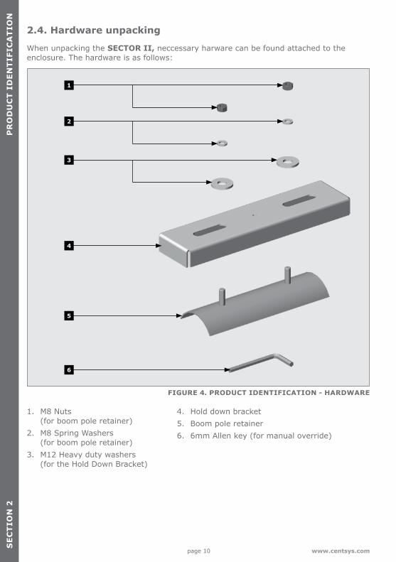
1. M8 Nuts (for boom pole retainer)
2. M8 Spring Washers (for boom pole retainer)
3. M12 Heavy duty washers (for the Hold Down Bracket)
4. Hold down bracket5. Boom pole retainer6. 6mm Allen key (for manual override)
FIGURE 4. PRODUCT IDENTIFICATION - HARDWARE
2.4. Hardware unpacking
When unpacking the SECTOR II, neccessary harware can be found attached to the enclosure. The hardware is as follows:
1
2
3
4
5
6
page 11www.centsys.com
3. Physical installation
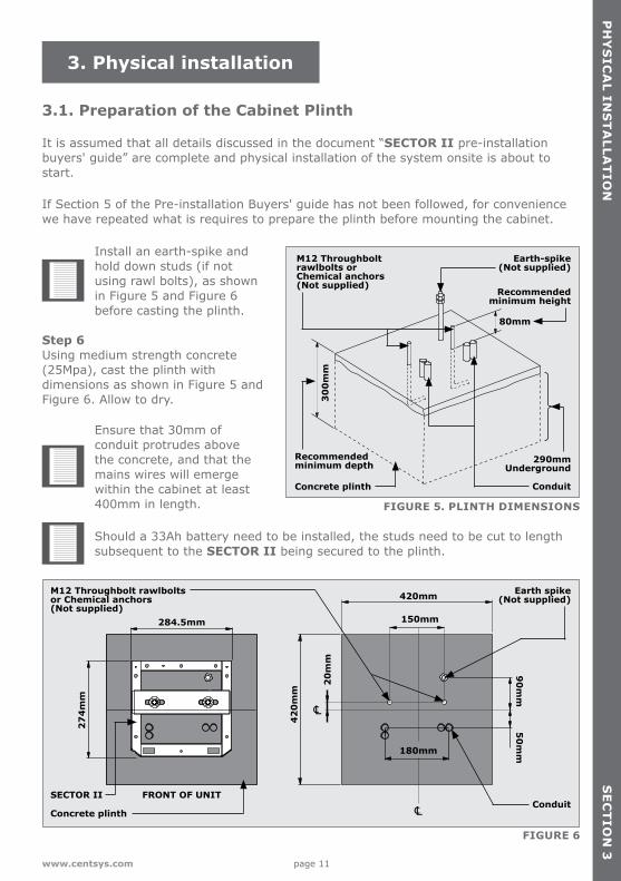
3.1. Preparation of the Cabinet Plinth
It is assumed that all details discussed in the document “SECTOR II pre-installation buyers' guide” are complete and physical installation of the system onsite is about to start.
If Section 5 of the Pre-installation Buyers' guide has not been followed, for convenience we have repeated what is requires to prepare the plinth before mounting the cabinet.
SE
CT
ION
3P
HY
SIC
AL IN
ST
ALLA
TIO
N
Install an earth-spike and hold down studs (if not using rawl bolts), as shown in Figure 5 and Figure 6 before casting the plinth.
Step 6 Using medium strength concrete (25Mpa), cast the plinth with dimensions as shown in Figure 5 and Figure 6. Allow to dry.
Ensure that 30mm of conduit protrudes above the concrete, and that the mains wires will emerge within the cabinet at least 400mm in length.
Should a 33Ah battery need to be installed, the studs need to be cut to length subsequent to the SECTOR II being secured to the plinth.
FIGURE 5. PLINTH DIMENSIONS
FIGURE 6
Recommendedminimum height
Earth-spike(Not supplied)
M12 Throughbolt rawlbolts or Chemical anchors(Not supplied)
Earth spike(Not supplied)
M12 Throughbolt rawlbolts or Chemical anchors(Not supplied)
Conduit
290mmUnderground
30
0m
m80mm
Concrete plinth
Recommendedminimum depth
284.5mm
420mm
150mm
20
mm
180mm
50
mm
90
mm
42
0m
m
FRONT OF UNIT
27
4m
m
Concrete plinthConduit
SECTOR II
page 12 www.centsys.com
SE
CT
ION
3P
HY
SIC
AL
INS
TA
LLA
TIO
N
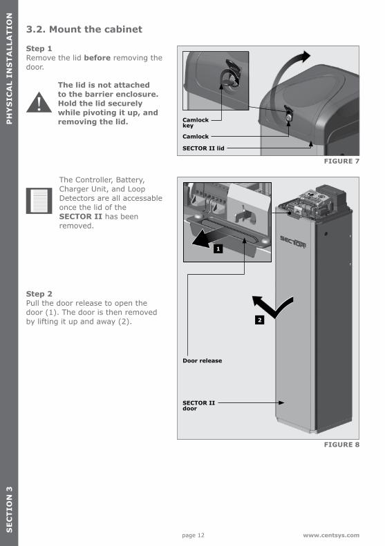
Step 1 Remove the lid before removing the door.
Step 2 Pull the door release to open the door (1). The door is then removed by lifting it up and away (2).
FIGURE 7
FIGURE 8
Camlock
Camlockkey
SECTOR II lid
SECTOR II door
Door release
2
1
The lid is not attached to the barrier enclosure. Hold the lid securely while pivoting it up, and removing the lid.
The Controller, Battery, Charger Unit, and Loop Detectors are all accessable once the lid of the SECTOR II has been removed.
3.2. Mount the cabinet
page 13www.centsys.com
PH
YS
ICA
L INS
TA
LLAT
ION
SE
CT
ION
3
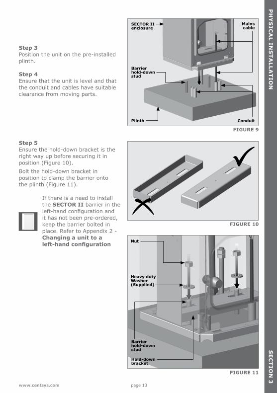
Step 3 Position the unit on the pre-installed plinth.
Step 4 Ensure that the unit is level and that the conduit and cables have suitable clearance from moving parts.
Step 5 Ensure the hold-down bracket is the right way up before securing it in position (Figure 10).Bolt the hold-down bracket in position to clamp the barrier onto the plinth (Figure 11).
If there is a need to install the SECTOR II barrier in the left-hand configuration and it has not been pre-ordered, keep the barrier bolted in place. Refer to Appendix 2 - Changing a unit to a left-hand configuration
FIGURE 9
FIGURE 10
FIGURE 11
Plinth
SECTOR II enclosure
Barrier hold-down stud
Barrier hold-down stud
Nut
Heavy dutyWasher(Supplied)
Hold-down bracket
Conduit
Mains cable
page 14 www.centsys.com
SE
CT
ION
3P
HY
SIC
AL
INS
TA
LLA
TIO
N
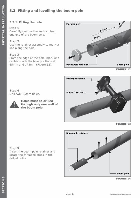
3.3. Fitting and levelling the boom pole
FIGURE 13
FIGURE 14
FIGURE 12
Step 5 Insert the boom pole retainer and locate the threaded studs in the drilled holes.
3.3.1. Fitting the pole
Step 1 Carefully remove the end cap from one end of the boom pole. Step 2Use the retainer assembly to mark a line along the pole.
Step 3From the edge of the pole, mark and centre punch the hole positions at 65mm and 175mm (Figure 12).
Marking pen
Drilling machine
8.5mm drill bit
Boom pole
Boom pole
Boom pole retainer
65mm
175mm
Boom pole retainer
Step 4 Drill two 8.5mm holes.
Holes must be drilled through only one wall of the boom pole.
page 15www.centsys.com
PH
YS
ICA
L INS
TA
LLAT
ION
SE
CT
ION
3
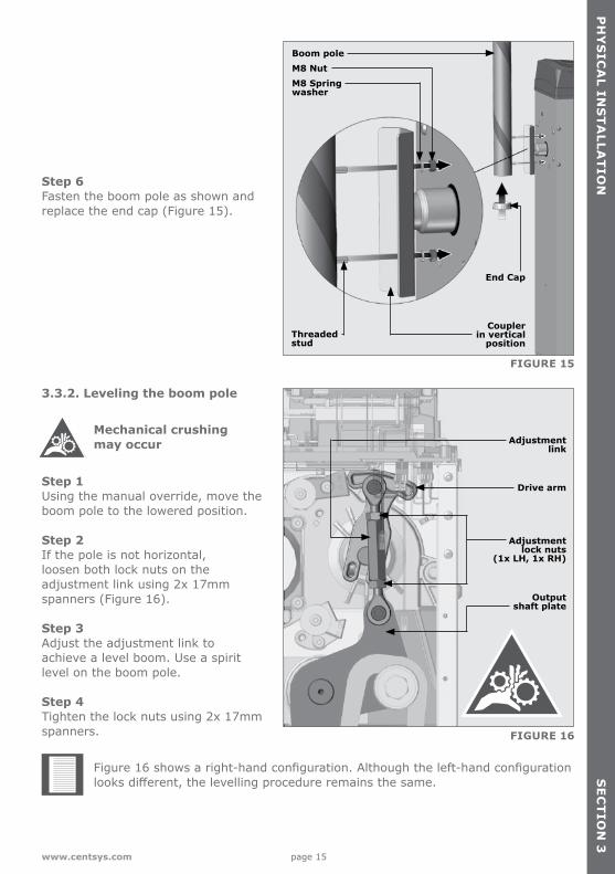
FIGURE 16
FIGURE 15
Step 6 Fasten the boom pole as shown and replace the end cap (Figure 15).
3.3.2. Leveling the boom pole
Step 1 Using the manual override, move the boom pole to the lowered position.
Step 2 If the pole is not horizontal, loosen both lock nuts on the adjustment link using 2x 17mm spanners (Figure 16).
Step 3 Adjust the adjustment link to achieve a level boom. Use a spirit level on the boom pole.
Step 4 Tighten the lock nuts using 2x 17mm spanners.
Boom poleM8 NutM8 Spring washer
Drive arm
Adjustment lock nuts
(1x LH, 1x RH)
Output shaft plate
Adjustment link
Threaded stud
Coupler in vertical
position
End Cap
Mechanical crushing may occur
Figure 16 shows a right-hand configuration. Although the left-hand configuration looks different, the levelling procedure remains the same.
page 16 www.centsys.com
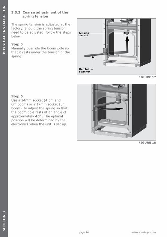
FIGURE 17
FIGURE 18
SE
CT
ION
3P
HY
SIC
AL
INS
TA
LLA
TIO
N
3.3.3. Coarse adjustment of the spring tension
The spring tension is adjusted at the factory. Should the spring tension need to be adjusted, follow the steps below.
Step 5 Manually override the boom pole so that it rests under the tension of the spring.
Step 6 Use a 24mm socket (4.5m and 6m boom) or a 17mm socket (3m boom) to adjust the spring so that the boom pole rests at an angle of approximately 45˚. The optimal position will be determined by the electronics when the unit is set up.
Tension bar nut
Ratchet spanner
page 17www.centsys.com
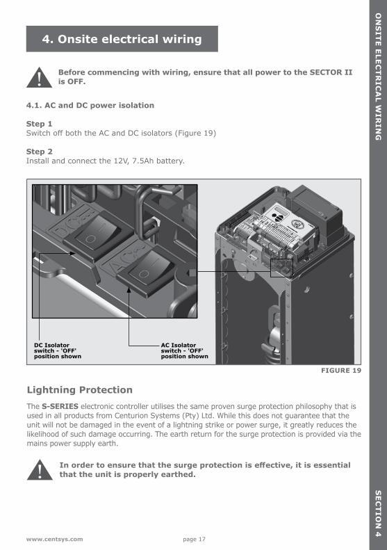
Before commencing with wiring, ensure that all power to the SECTOR II is OFF.
Lightning Protection The S-SERIES electronic controller utilises the same proven surge protection philosophy that is used in all products from Centurion Systems (Pty) Ltd. While this does not guarantee that the unit will not be damaged in the event of a lightning strike or power surge, it greatly reduces the likelihood of such damage occurring. The earth return for the surge protection is provided via the mains power supply earth.
In order to ensure that the surge protection is effective, it is essential that the unit is properly earthed.
ON
SIT
E E
LEC
TR
ICA
L WIR
ING
SE
CT
ION
4
4. Onsite electrical wiring
FIGURE 19
4.1. AC and DC power isolation
Step 1 Switch off both the AC and DC isolators (Figure 19)
Step 2 Install and connect the 12V, 7.5Ah battery.
DC Isolator switch - 'OFF' position shown
AC Isolator switch - 'OFF' position shown
page 18 www.centsys.com
SE
CT
ION
4O
NS
ITE
ELE
CT
RIC
AL
WIR
ING
FIGURE 22
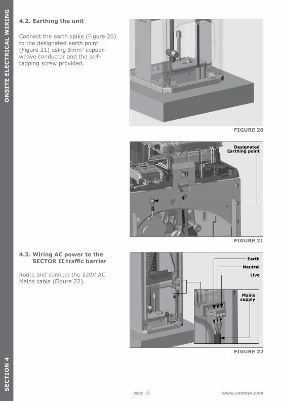
Earth
Neutral
Live
4.3. Wiring AC power to the SECTOR II traffic barrier
Route and connect the 220V AC Mains cable (Figure 22).
Mains supply
4.2. Earthing the unit
Connect the earth spike (Figure 20)to the designated earth point (Figure 21) using 5mm2 copper-weave conductor and the self-tapping screw provided.
FIGURE 20
Earth spike(Not supplied)
FIGURE 21
Designated Earthing point
page 19www.centsys.com
ON
SIT
E E
LEC
TR
ICA
L WIR
ING
SE
CT
ION
4
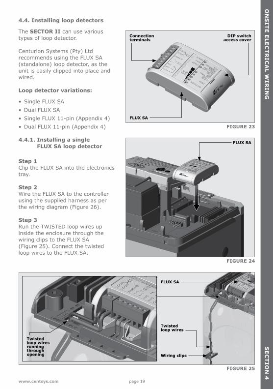
4.4. Installing loop detectors
The SECTOR II can use various types of loop detector. Centurion Systems (Pty) Ltd recommends using the FLUX SA (standalone) loop detector, as the unit is easily clipped into place and wired.
Loop detector variations:
• Single FLUX SA • Dual FLUX SA• Single FLUX 11-pin (Appendix 4)• Dual FLUX 11-pin (Appendix 4)
4.4.1. Installing a single FLUX SA loop detector
Step 1 Clip the FLUX SA into the electronics tray.
Step 2 Wire the FLUX SA to the controller using the supplied harness as per the wiring diagram (Figure 26).
Step 3 Run the TWISTED loop wires up inside the enclosure through the wiring clips to the FLUX SA(Figure 25). Connect the twisted loop wires to the FLUX SA.
FIGURE 23
FIGURE 24
FIGURE 25
FLUX SA
DIP switchaccess cover
FLUX SA
FLUX SA
Twisted loop wires
Wiring clips
Connection terminals
Twisted loop wiresrunning throughopening
page 20 www.centsys.com
SE
CT
ION
4O
NS
ITE
ELE
CT
RIC
AL
WIR
ING
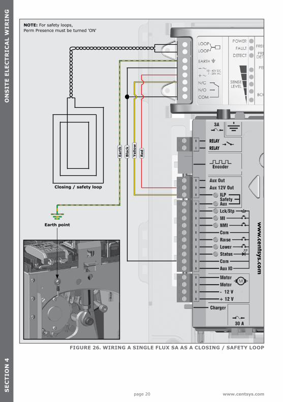
FIGURE 26. WIRING A SINGLE FLUX SA AS A CLOSING / SAFETY LOOP
Closing / safety loop
Bla
ck
Eart
h
Yel
low
Red
Earth point
NOTE: For safety loops, Perm Presence must be turned 'ON'
ww
w.ce
ntsys.co
m
RELAYRELAY
page 21www.centsys.com
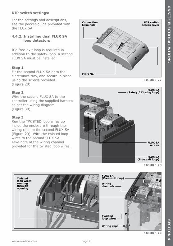
DIP switch settings:
For the settings and descriptions, see the pocket-guide provided with the FLUX SA.
4.4.2. Installing dual FLUX SA loop detectors
If a free-exit loop is required in addition to the safety-loop, a second FLUX SA must be installed.
Step 1 Fit the second FLUX SA onto the electronics tray, and secure in place using the screws provided. (Figure 28).
Step 2 Wire the second FLUX SA to the controller using the supplied harness as per the wiring diagram (Figure 30).
Step 3 Run the TWISTED loop wires up inside the enclosure through the wiring clips to the second FLUX SA(Figure 29). Wire the twisted loop wires to the second FLUX SA.Take note of the wiring channel provided for the twisted loop wires.
FIGURE 27
FIGURE 28
FIGURE 29
FLUX SA
DIP switchaccess cover
FLUX SA (Safety / Closing loop)
FLUX SA (Free exit loop)
FLUX SA screws
FLUX SA (Free-exit loop)
Connection terminals
ON
SIT
E E
LEC
TR
ICA
L WIR
ING
SE
CT
ION
4
Twisted loop wires
Wiring channels
Wiring clips
Twisted loop wiresrunning throughopening
page 22 www.centsys.com
SE
CT
ION
4O
NS
ITE
ELE
CT
RIC
AL
WIR
ING
ww
w.ce
ntsys.co
m
RELAY
RELAY
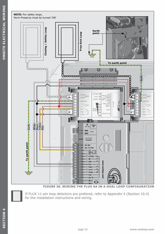
FIGURE 30. WIRING THE FLUX SA IN A DUAL LOOP CONFIGURATION
Free
-Exi
t Lo
op
Clo
sin
g /
Saf
ety
Loop Earth
point
To earth point
To e
arth
poi
nt
If FLUX 11-pin loop detectors are prefered, refer to Appendix 4 (Section 10.4) for the installation instructions and wiring.
Bla
ck
Eart
h
Eart
h
Wh
ite
Red
Yel
low
NOTE: For safety loops, Perm Presence must be turned 'ON'
page 23www.centsys.com
SE
CT
ION
5B
AS
IC C
ON
TR
OLLE
R S
ET
UP
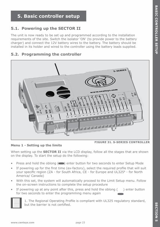
5. Basic controller setup
5.1. Powering up the SECTOR IIThe unit is now ready to be set up and programmed according to the installation requirements of the site. Switch the isolator ‘ON’ (to provide power to the battery charger) and connect the 12V battery wires to the battery. The battery should be installed in its holder and wired to the controller using the battery leads supplied.
5.2. Programming the controller
Menu 1 - Setting up the limits
When setting up the SECTOR II via the LCD display, follow all the stages that are shown on the display. To start the setup do the following:
• Press and hold the oblong ( ) enter button for two seconds to enter Setup Mode• If powering up for the first time (ex-factory), select the required profile that will suit
your specific region (ZA - for South Africa, CE - for Europe and UL3251 - for North America/ Canada)
• With this set, the system will automatically proceed to the Limit Setup menu. Follow the on-screen instructions to complete the setup procedure
• If powering up at any point after this, press and hold the oblong ( ) enter button for two seconds to enter the programming menu again
1. The Regional Operating Profile is compliant with UL325 regulatory standard, but the barrier is not certified.
FIGURE 31. S-SERIES CONTROLLER
page 24 www.centsys.com
SE
CT
ION
5B
AS
IC C
ON
TR
OLL
ER
SE
TU
P
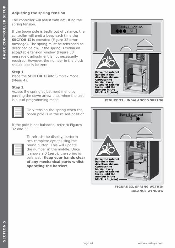
Adjusting the spring tension
The controller will assist with adjusting the spring tension.
If the boom pole is badly out of balance, the controller will emit a beep each time the SECTOR II is operated (Figure 32 error message). The spring must be tensioned as described below. If the spring is within an acceptable tension window (Figure 33 message), adjustment is not necessarily required. However, the number in the block should ideally be zero.
Step 1 Place the SECTOR II into Simplex Mode (Menu 4).
Step 2 Access the spring adjustment menu by pushing the down arrow once when the unit is out of programming mode.
Only tension the spring when the boom pole is in the raised position.
If the pole is not balanced, refer to Figures 32 and 33.
To refresh the display, perform two complete cycles using the round button. This will update the number in the middle. Once it shows a 0 (zero), the spring is balanced. Keep your hands clear of any mechanical parts whilst operating the barrier!
FIGURE 33. SPRING WITHIN BALANCE WINDOW
FIGURE 32. UNBALANCED SPRING
Drive the ratchet handle in the direction shown. Operate the barrier every couple of ratchet turns until the number in the block is 0 (zero)
Drive the ratchet handle in the direction shown. Operate the barrier every couple of ratchet turns until the number in the block is 0 (zero)
Tighten Spring
11
Tighten Spring
11
page 25www.centsys.com
SE
CT
ION
5
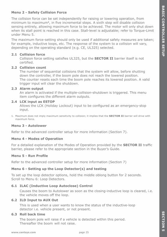
Menu 2 - Safety Collision Force
The collision force can be set independently for raising or lowering operation, from minimum to maximum1, in five incremental steps. A sixth step will disable collision sensing entirely, allowing maximum force to be achieved. The motor will only shut down when its stall point is reached in this case. Stall-level is adjustable; refer to Torque-Limit under Menu 5. The maximum force-setting should only be used if additional safety measures are taken; for example, inductive loops, etc. The response of the system to a collision will vary, depending on the operating standard (e.g. CE, UL325) selected.
2.1 Collision force Collision force setting satisfies UL325, but the SECTOR II barrier itself is not certified.2.2 Collision count The number of sequential collisions that the system will allow, before shutting down the controller, if the boom pole does not reach the lowered position. The counter resets each time the boom pole reaches its lowered position. A valid trigger input will clear the shutdown.2.3 Alarm output An alarm is activated if the multiple-collision-shutdown is triggered. This menu item configures the different alarm outputs.2.4 LCK input as ESTOP Allows the LCK (Holiday Lockout) input to be configured as an emergency-stop input.
1. Maximum does not imply maximum sensitivity to collision; it implies that the SECTOR II barrier will drive with maximum force.
Menu 3 - Autolower
Refer to the advanced controller setup for more information (Section 7).
Menu 4 - Modes of Operation
For a detailed explanation of the Modes of Operation provided by the SECTOR II traffic barrier, please refer to the appropriate section in the Buyer’s Guide.
Menu 5 - Run Profile
Refer to the advanced controller setup for more information (Section 7)
Menu 6 - Setting up the Loop Detector(s) and testing
To set up the loop detector options, hold the middle oblong button for 2 seconds. Scroll to Menu 6: Loop Detectors.
6.1 ILAC (Inductive Loop Autoclose) Control Causes the boom to Autolower as soon as the closing-inductive loop is cleared, i.e. the vehicle moves off the loop.6.2 ILD Input to AUX Out This is used when a user wants to know the status of the inductive-loop detector i.e. vehicle present, or not present.6.3 Roll back time The boom pole will raise if a vehicle is detected within this period. Thereafter the boom will not raise.
BA
SIC
CO
NT
RO
LLER
SE
TU
P
page 26 www.centsys.com
SE
CT
ION
5B
AS
IC C
ON
TR
OLL
ER
SE
TU
P
6.4 FRX (Free-exit) loop direction Allows a single access point with bi-directional traffic to make use of a free-exit loop. Due consideration must be given to closing and free-exit loop positioning.6.5 Inductive loop alarms
While the boom pole is lowered, this feature allows the following alarms:• Presence alarm - Activates an alarm if the closing-loop has been continuously
activated for a predefined time. The alarm will remain activated while the closing-loop is activated
• Presence time - The time for which the closing-loop must be continuously activated before the alarm is activated
• Break-in alarm - Activates an alarm if the closing-loop is activated while the boom is lowered. The alarm remains active while the closing-loop is activated, and for a period of 30 seconds thereafter. This time is fixed
• Alarm output - This menu item configures the different alarm outputs
Once the required changes are made, exit the menu by pressing the round button.
Menu 7 to Menu 14Refer to the advanced controller setup for more information (Section 7)
page 27www.centsys.com
6. Installation handover
Once the installation has been successfully completed and tested, it is important to explain the operation and safety requirements of the system to the end-user.
NEVER ASSUME THE USER KNOWS HOW TO SAFELY OPERATE AN AUTOMATED BARRIER!
Even if the user has used one before, it does not mean he knows how to SAFELY operate it. Make sure that the user fully understands the following safety requirements before finally handing over the site.
The following needs to be understood by the user:• How to operate the manual release mechanism
(Show them how by demonstration)• How the safety loops and all other safety features work
(Show them how by demonstration)• All the features and benefits of the operator, i.e. Safety loops, etc• All the safety considerations associated with operating an automated barrier.
The user should be able to pass this knowledge on to all other users of the automated system and must be made aware of this responsibility
• Do not activate the barrier unless you can see it and can determine that its area of travel is clear of people, pets, or other obstructions
• NO ONE MAY GO UNDER A MOVING BARRIER. Always keep people and objects away from the barrier
• NEVER LET CHILDREN OPERATE OR PLAY WITH THE BARRIER CONTROLS, and do not allow children or pets near the barrier area
• Be careful with moving parts and avoid close proximity to areas where fingers or hands could be pinched
• Secure all easily-accessed barrier operator controls in order to prevent its unauthorised use
• Keep the automated barrier system properly maintained, and ensure that all working areas are free of objects that could affect its operation and safety
• On a monthly basis, check the obstruction detection system and safety devices for correct operation
• All repair and service work to this product must be done by a suitably qualified person
• This product was designed and built strictly for the use indicated in this documentation. Any other use, not expressly indicated here, could compromise the good condition/operation of the product and/or be a source of danger!
Neither Centurion Systems (Pty) Ltd, nor its subsidiaries, accepts any liability caused by improper use of the product, or for use other than that for which the automated system was intended.
Ensure that the customer is in possession of the user guide and that you have completed the installation details in the back of the manual.
SE
CT
ION
6IN
ST
ALLA
TIO
N H
AN
D O
VE
R

page 28 www.centsys.com
Standard installation is now completeAt this point, a simple installation of a SECTOR II has been completed. Should the installation require other adjustments to be made to the standard settings, these can be found from Section 7 onwards. We recommend that these menus be carefully considered and adjustments applied to the installation, if required.
SE
CT
ION
6IN
ST
ALL
AT
ION
HA
ND
OV
ER
page 29www.centsys.com
7. Advanced controller setup
Setting up additional features for the SECTOR II barrierThe SECTOR II navigation map (Section 7.1), provides the full menu of features that can be set up on the system.A brief explanation of each feature is provided under each menu heading. When setting up additional features, all the stages that have to be followed are clearly provided via the display. It is only necessary to note the following:
• To get into Setup Mode, press and hold the oblong ( ) enter button for two seconds and follow the onscreen instructions
• The buttons provided on the controller for navigating the system are blank because their functions vary within each menu and are indicated on the LCD display
SE
CT
ION
7A
DV
AN
CE
D C
ON
TR
OLLE
R S
ET
UP
page 30 www.centsys.com
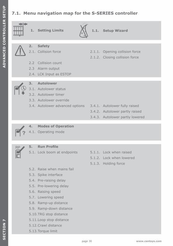
1. Setting Limits 1.1. Setup Wizard
2. Safety2.1. Collision force 2.1.1. Opening collision force
2.1.2. Closing collision force
2.2 Collision count
2.3 Alarm output
2.4. LCK Input as ESTOP
3. Autolower3.1. Autolower status
3.2. Autolower timer
3.3. Autolower override
3.4. Autolower advanced options 3.4.1. Autolower fully raised
3.4.2. Autolower partly raised
3.4.3. Autolower partly lowered
4. Modes of Operation4.1. Operating mode
5. Run Profile5.1. Lock boom at endpoints 5.1.1. Lock when raised
5.1.2. Lock when lowered
5.1.3. Holding force
5.2. Raise when mains fail
5.3. Spike interface
5.4. Pre-raising delay
5.5. Pre-lowering delay
5.6. Raising speed
5.7. Lowering speed
5.8. Ramp-up distance
5.9. Ramp-down distance
5.10.TRG stop distance
5.11.Loop stop distance
5.12.Crawl distance
5.13.Torque limit
7.1. Menu navigation map for the S-SERIES controller
SE
CT
ION
7A
DV
AN
CE
D C
ON
TR
OLL
ER
SE
TU
P
page 31www.centsys.com
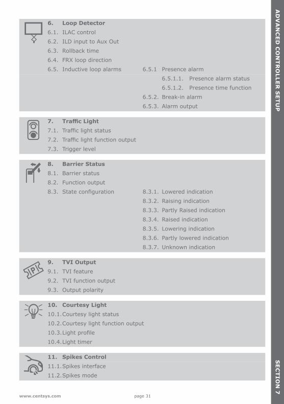
6. Loop Detector6.1. ILAC control
6.2. ILD input to Aux Out
6.3. Rollback time
6.4. FRX loop direction
6.5. Inductive loop alarms 6.5.1 Presence alarm
6.5.1.1. Presence alarm status
6.5.1.2. Presence time function
6.5.2. Break-in alarm
6.5.3. Alarm output
7. Traffic Light7.1. Traffic light status
7.2. Traffic light function output
7.3. Trigger level
8. Barrier Status8.1. Barrier status
8.2. Function output
8.3. State configuration 8.3.1. Lowered indication
8.3.2. Raising indication
8.3.3. Partly Raised indication
8.3.4. Raised indication
8.3.5. Lowering indication
8.3.6. Partly lowered indication
8.3.7. Unknown indication
9. TVI Output9.1. TVI feature
9.2. TVI function output
9.3. Output polarity
10. Courtesy Light10.1.Courtesy light status
10.2.Courtesy light function output
10.3.Light profile
10.4.Light timer
11. Spikes Control11.1.Spikes interface
11.2.Spikes mode
AD
VA
NC
ED
CO
NT
RO
LLER
SE
TU
PS
EC
TIO
N 7
page 32 www.centsys.com
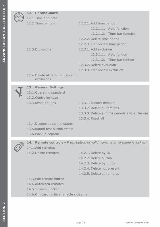
12. ChronoGuard12.1.Time and date
12.2.Time periods 12.2.1. Add time period
12.2.1.1. Auto function
12.2.1.2. Time-bar function
12.2.2. Delete time period
12.2.3. Edit review time period
12.3.Exclusions 12.3.1. Add exclusion
12.3.1.1. Auto funtion
12.3.1.2. Time-bar funtion
12.3.2. Delete exclusion
12.3.3. Edit review exclusion
12.4 Delete all time periods and exclusions
13. General Settings13.1.Operating standard
13.2.Controller type
13.3.Reset options 13.3.1. Factory defaults
13.3.2. Delete all remotes
13.3.3. Delete all time periods and exclusions
13.3.4. Reset all
13.4.Diagnostic screen status
13.5.Round test button status
13.6.Backup eeprom
14. Remote controls - Press button of valid transmitter (if menu is locked)
14.1.Add remotes
14.2.Delete remotes 14.2.1. Delete by ID
14.2.2. Delete button
14.2.3. Delete by button
14.2.4. Delete not present
14.2.5. Delete all remotes
14.3.Edit remote button
14.4.Autolearn remotes
14.5.Tx menu locked
14.6.Onboard reciever enable / disable
SE
CT
ION
7A
DV
AN
CE
D C
ON
TR
OLL
ER
SE
TU
P
page 33www.centsys.com
SE
CT
ION
7A
DV
AN
CE
D C
ON
TR
OLL
ER
SE
TU
P
The following provides additional information of each menu. Menu 1 and Menu 2Refer to the basic controller setup for more information (Section 5).
Menu 3 - AutolowerThe SECTOR II can be set to Autolower the boom under many different circumstances. The following options are available;
3.1 Autolower status If enabled, the boom pole will automatically lower after a preset Autolower time.3.2 Autolower time The Autolower time can be set anywhere from 1 to 240 seconds (four minutes).3.3 Autolower override If turned on, this menu provides a way for a user to temporarily turn off Autolower. To achieve the functionality, the user would activate and maintain the Memory Input for longer than the Autolower Override Time. Activate Memory Input to clear the override.3.4 Autolower advanced options Set the conditions under which the boom pole will automatically lower. More than one condition can be selected:
• Autolower fully raised Automatically lower the boom if boom pole is fully raised
• Autolower on partly raised Automatically lower the boom pole if it has been stopped partially raised
• Autolower on partly lowered Automatically lower the boom pole if it has been stopped partially lowered
Menu 4 - Modes of OperationRefer to the Pre-installation Buyer's Guide for more information.
Menu 5 - Run ProfileThe run profile of the SECTOR II can also be set. This allows the overall behaviour of the traffic barrier to be fine-tuned in order to meet the user’s unique requirements;
5.1 Lock boom pole at endpoints:
Fail-safe modeIn the event that electronic locking is not required and mechanical locking is preferred, refer to Section 10.3 to adjust the endstops into their locking positions.
• Lock when raised - mechanically lock boom pole in raised position. Use manual override key to override
• Lock when lowered - as per above for lowered position• Holding force - force used to automatically hold the boom pole in the raised or
lowered position if ‘lock at endpoints’ is not selected
AD
VA
NC
ED
CO
NT
RO
LLER
SE
TU
PS
EC
TIO
N 7
page 34 www.centsys.com
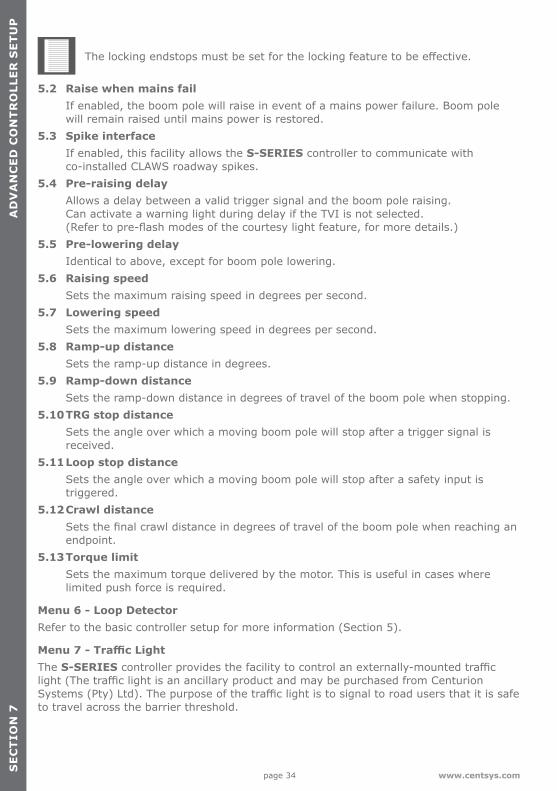
The locking endstops must be set for the locking feature to be effective.
5.2 Raise when mains fail If enabled, the boom pole will raise in event of a mains power failure. Boom pole will remain raised until mains power is restored.5.3 Spike interface If enabled, this facility allows the S-SERIES controller to communicate with co-installed CLAWS roadway spikes.5.4 Pre-raising delay Allows a delay between a valid trigger signal and the boom pole raising. Can activate a warning light during delay if the TVI is not selected. (Refer to pre-flash modes of the courtesy light feature, for more details.)5.5 Pre-lowering delay Identical to above, except for boom pole lowering.5.6 Raising speed Sets the maximum raising speed in degrees per second.5.7 Lowering speed Sets the maximum lowering speed in degrees per second.5.8 Ramp-up distance Sets the ramp-up distance in degrees.5.9 Ramp-down distance Sets the ramp-down distance in degrees of travel of the boom pole when stopping.5.10 TRG stop distance Sets the angle over which a moving boom pole will stop after a trigger signal is received.5.11 Loop stop distance Sets the angle over which a moving boom pole will stop after a safety input is triggered.5.12 Crawl distance Sets the final crawl distance in degrees of travel of the boom pole when reaching an endpoint.5.13 Torque limit Sets the maximum torque delivered by the motor. This is useful in cases where limited push force is required.
Menu 6 - Loop DetectorRefer to the basic controller setup for more information (Section 5).
Menu 7 - Traffic LightThe S-SERIES controller provides the facility to control an externally-mounted traffic light (The traffic light is an ancillary product and may be purchased from Centurion Systems (Pty) Ltd). The purpose of the traffic light is to signal to road users that it is safe to travel across the barrier threshold.
SE
CT
ION
7A
DV
AN
CE
D C
ON
TR
OLL
ER
SE
TU
P
page 35www.centsys.com
SE
CT
ION
7A
DV
AN
CE
D C
ON
TR
OLL
ER
SE
TU
P
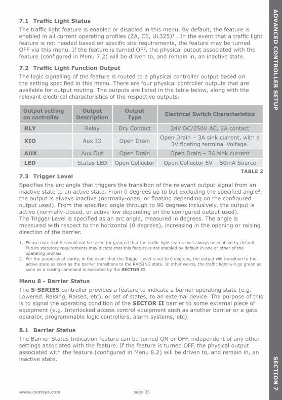
7.1 Traffic Light StatusThe traffic light feature is enabled or disabled in this menu. By default, the feature is enabled in all current operating profiles (ZA, CE, UL325)1 . In the event that a traffic light feature is not needed based on specific site requirements, the feature may be turned OFF via this menu. If the feature is turned OFF, the physical output associated with the feature (configured in Menu 7.2) will be driven to, and remain in, an inactive state.
7.2 Traffic Light Function OutputThe logic signalling of the feature is routed to a physical controller output based on the setting specified in this menu. There are four physical controller outputs that are available for output routing. The outputs are listed in the table below, along with the relevant electrical characteristics of the respective outputs:
7.3 Trigger LevelSpecifies the arc angle that triggers the transition of the relevant output signal from an inactive state to an active state. From 0 degrees up to but excluding the specified angle2, the output is always inactive (normally-open, or floating depending on the configured output used). From the specified angle through to 90 degrees inclusively, the output is active (normally-closed, or active low depending on the configured output used).The Trigger Level is specified as an arc angle, measured in degrees. The angle is measured with respect to the horizontal (0 degrees), increasing in the opening or raising direction of the barrier.
1. Please note that it should not be taken for granted that the traffic light feature will always be enabled by default. Future statutory requirements may dictate that this feature is not enabled by default in one or other of the operating profiles.
2. For the purposes of clarity, in the event that the Trigger Level is set to 0 degrees, the output will transition to the active state as soon as the barrier transitions to the RAISING state. In other words, the traffic light will go green as soon as a raising command is executed by the SECTOR II.
Menu 8 - Barrier StatusThe S-SERIES controller provides a feature to indicate a barrier operating state (e.g. Lowered, Raising, Raised, etc), or set of states, to an external device. The purpose of this is to signal the operating condition of the SECTOR II barrier to some external piece of equipment (e.g. Interlocked access control equipment such as another barrier or a gate operator, programmable logic controllers, alarm systems, etc).
8.1 Barrier StatusThe Barrier Status Indication feature can be turned ON or OFF, independent of any other settings associated with the feature. If the feature is turned OFF, the physical output associated with the feature (configured in Menu 8.2) will be driven to, and remain in, an inactive state.
Output setting on controller
Output Description
Output Type Electrical Switch Characteristics
RLY Relay Dry Contact 24V DC/250V AC, 2A contact
XIO Aux IO Open Drain Open Drain – 3A sink current, with a 3V floating terminal Voltage.
AUX Aux Out Open Drain Open Drain – 3A sink current
LED Status LED Open Collector Open Collector 5V – 50mA Source TABLE 2
AD
VA
NC
ED
CO
NT
RO
LLER
SE
TU
PS
EC
TIO
N 7
page 36 www.centsys.com
SE
CT
ION
7
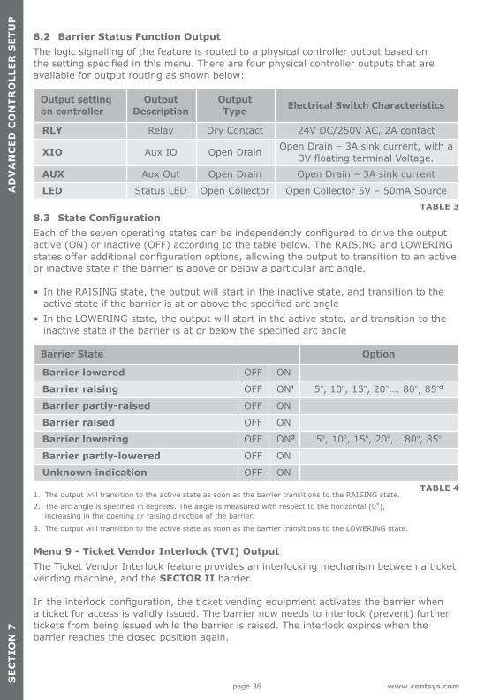
8.2 Barrier Status Function OutputThe logic signalling of the feature is routed to a physical controller output based on the setting specified in this menu. There are four physical controller outputs that are available for output routing as shown below:
8.3 State ConfigurationEach of the seven operating states can be independently configured to drive the output active (ON) or inactive (OFF) according to the table below. The RAISING and LOWERING states offer additional configuration options, allowing the output to transition to an active or inactive state if the barrier is above or below a particular arc angle.
• In the RAISING state, the output will start in the inactive state, and transition to the active state if the barrier is at or above the specified arc angle
• In the LOWERING state, the output will start in the active state, and transition to the inactive state if the barrier is at or below the specified arc angle
1. The output will transition to the active state as soon as the barrier transitions to the RAISING state.2. The arc angle is specified in degrees. The angle is measured with respect to the horizontal (0°),
increasing in the opening or raising direction of the barrier.
3. The output will transition to the active state as soon as the barrier transitions to the LOWERING state.
Menu 9 - Ticket Vendor Interlock (TVI) OutputThe Ticket Vendor Interlock feature provides an interlocking mechanism between a ticket vending machine, and the SECTOR II barrier.
In the interlock configuration, the ticket vending equipment activates the barrier when a ticket for access is validly issued. The barrier now needs to interlock (prevent) further tickets from being issued while the barrier is raised. The interlock expires when the barrier reaches the closed position again.
TABLE 3
Output setting on controller
Output Description
Output Type Electrical Switch Characteristics
RLY Relay Dry Contact 24V DC/250V AC, 2A contact
XIO Aux IO Open Drain Open Drain – 3A sink current, with a 3V floating terminal Voltage.
AUX Aux Out Open Drain Open Drain – 3A sink current
LED Status LED Open Collector Open Collector 5V – 50mA Source
SE
CT
ION
7A
DV
AN
CE
D C
ON
TR
OLL
ER
SE
TU
P
Barrier State Option
Barrier lowered OFF ON
Barrier raising OFF ON1 5°, 10°, 15°, 20°,… 80°, 85°2
Barrier partly-raised OFF ON
Barrier raised OFF ON
Barrier lowering OFF ON3 5°, 10°, 15°, 20°,… 80°, 85°
Barrier partly-lowered OFF ON
Unknown indication OFF ONTABLE 4
page 37www.centsys.com
SE
CT
ION
7A
DV
AN
CE
D C
ON
TR
OLL
ER
SE
TU
P
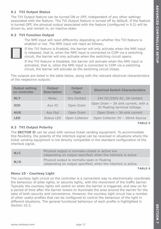
9.1 TVI Output StatusThe TVI Output feature can be turned ON or OFF, independent of any other settings associated with the feature. The TVI Output feature is turned off by default. If the feature is turned OFF, the physical output associated with the feature (configured in 9.2) will be driven to, and remain in, an inactive state.
9.2 TVI Function OutputThe NMI input will react differently depending on whether the TVI feature is enabled or not. The NMI input will react as follows; If the TVI feature is Enabled, the barrier will only activate when the NMI input is released, that is, when the NMI input is connected to COM via a switching circuit, the barrier will only activate when the switching circuit opens.If the TVI feature is Disabled, the barrier will activate when the NMI input is activated, that is, when the NMI input is connected to COM via a switching circuit, the barrier will activate as the switching circuit closes.
The outputs are listed in the table below, along with the relevant electrical characteristics of the respective outputs:
9.3 TVI Output PolarityThe SECTOR II can be used with various ticket vending equipment. To accommodate this flexibility, the polarity of the interlock signal can be reversed in situations where the ticket vending equipment is not directly compatible in the standard configuration of the interlock signal.
Menu 10 - Courtesy LightThe courtesy light circuit on the controller is a convenient way to electronically coordinate the behaviour of pillar lights, or security lights, with the movement of the traffic barrier. Typically the courtesy lights will switch on when the barrier is triggered, and stay on for a period of time after the barrier lowers to illuminate the area around the barrier for the sake of both security and convenience. However, the courtesy light circuit has a number of other useful profiles that can be configured to control the behaviour of the light in different situations. The general functional behaviour of each profile is highlighted in Section 10.3.
AD
VA
NC
ED
CO
NT
RO
LLER
SE
TU
PS
EC
TIO
N 7
TABLE 5
Output setting on controller
Output Description
Output Type Electrical Switch Characteristics
RLY Relay Dry Contact 24V DC/250V AC, 2A contact
XIO Aux IO Open Drain Open Drain – 3A sink current, with a 3V floating terminal Voltage.
AUX Aux Out Open Drain Open Drain – 3A sink current
LED Status LED Open Collector Open Collector 5V – 50mA Source
N/C Physical output is normally-closed or active low (depending on output specified) when the interlock is active
N/O Physical output is normally-open or floating (depending on output specified) when the interlock is active.
TABLE 6
page 38 www.centsys.com
AD
VA
NC
ED
CO
NT
RO
LLER
SE
TU
P
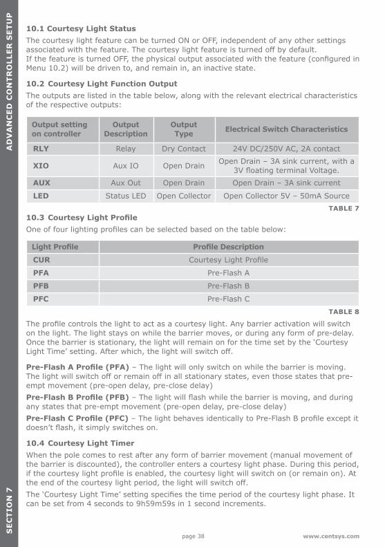
10.1 Courtesy Light StatusThe courtesy light feature can be turned ON or OFF, independent of any other settings associated with the feature. The courtesy light feature is turned off by default. If the feature is turned OFF, the physical output associated with the feature (configured in Menu 10.2) will be driven to, and remain in, an inactive state.
10.2 Courtesy Light Function OutputThe outputs are listed in the table below, along with the relevant electrical characteristics of the respective outputs:
10.3 Courtesy Light ProfileOne of four lighting profiles can be selected based on the table below:
The profile controls the light to act as a courtesy light. Any barrier activation will switch on the light. The light stays on while the barrier moves, or during any form of pre-delay. Once the barrier is stationary, the light will remain on for the time set by the ‘Courtesy Light Time’ setting. After which, the light will switch off.
Pre-Flash A Profile (PFA) – The light will only switch on while the barrier is moving. The light will switch off or remain off in all stationary states, even those states that pre-empt movement (pre-open delay, pre-close delay) Pre-Flash B Profile (PFB) – The light will flash while the barrier is moving, and during any states that pre-empt movement (pre-open delay, pre-close delay)Pre-Flash C Profile (PFC) – The light behaves identically to Pre-Flash B profile except it doesn’t flash, it simply switches on.
10.4 Courtesy Light TimerWhen the pole comes to rest after any form of barrier movement (manual movement of the barrier is discounted), the controller enters a courtesy light phase. During this period, if the courtesy light profile is enabled, the courtesy light will switch on (or remain on). At the end of the courtesy light period, the light will switch off.The ‘Courtesy Light Time’ setting specifies the time period of the courtesy light phase. It can be set from 4 seconds to 9h59m59s in 1 second increments.
TABLE 7
Output setting on controller
Output Description
Output Type Electrical Switch Characteristics
RLY Relay Dry Contact 24V DC/250V AC, 2A contact
XIO Aux IO Open Drain Open Drain – 3A sink current, with a 3V floating terminal Voltage.
AUX Aux Out Open Drain Open Drain – 3A sink current
LED Status LED Open Collector Open Collector 5V – 50mA Source
SE
CT
ION
7A
DV
AN
CE
D C
ON
TR
OLL
ER
SE
TU
P
Light Profile Profile Description
CUR Courtesy Light Profile
PFA Pre-Flash A
PFB Pre-Flash B
PFC Pre-Flash C
TABLE 8
page 39www.centsys.com
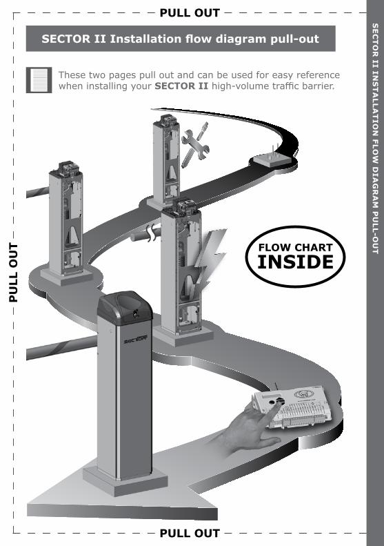
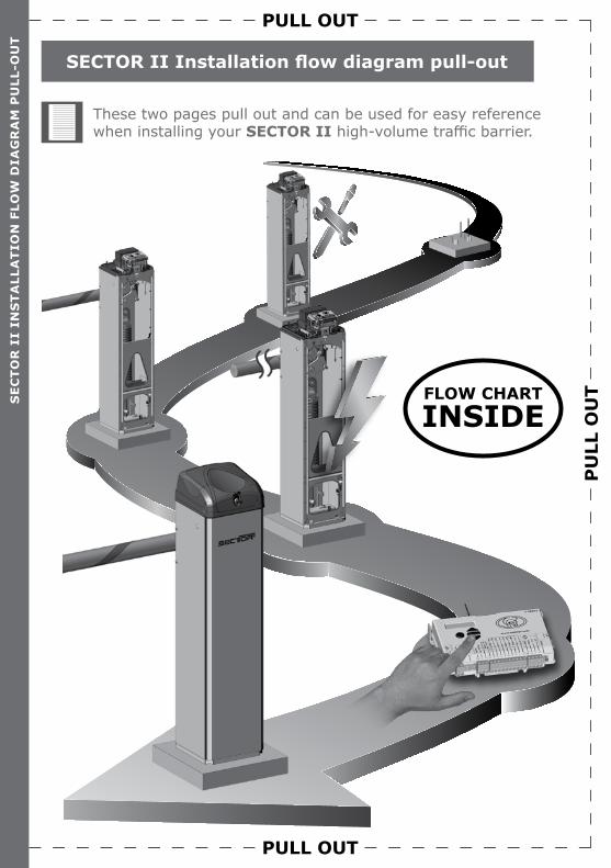
SECTOR II Installation flow diagram pull-out
SE
CT
OR
II INS
TA
LLAT
ION
FLOW
DIA
GR
AM
PU
LL-OU
T
These two pages pull out and can be used for easy reference when installing your SECTOR II high-volume traffic barrier.
PULL OUT
FLOW CHARTINSIDE
PU
LL O
UT
PULL OUT
Mou
nt t
he c
abin
etSec
tion
3
Fit
the
pole
Sec
tion
3.2Pr
e-in
stal
latio
n(r
efer
to
pre-
inst
alla
tion
buye
rs g
uide
)
Eart
h an
d m
ains
Sec
tion
4.1
Inst
all F
LUX S
A lo
op d
etec
tor(
s)Sec
tion
4.4
Inst
all 1
1-pi
n lo
op d
etec
tor(
s)Sec
tion
10.4
AC a
nd D
C is
olat
ors
Sec
tion
4.3
Cha
ngin
g or
ient
atio
nSec
tion
10.2
Inst
alla
tion
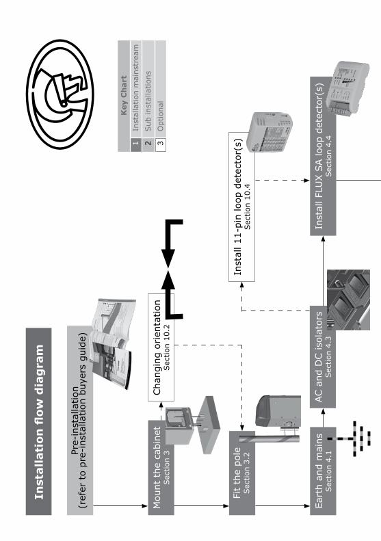
flow
dia
gra
m
Key
Ch
art
1In
stal
latio
n m
ains
trea
m
2Sub
inst
alla
tions
3O
ptio
nal
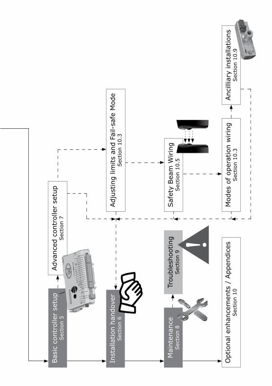
Bas
ic c
ontr
olle
r se
tup
Sec
tion
5
Saf
ety
Bea
m W
irin
gSec
tion
10.5
Mod
es o
f op
erat
ion
wirin
gSec
tion
10.3
Inst
alla
tion
hand
over
Sec
tion
6
Mai
nten
ance
Sec
tion
8
Adv
ance
d co
ntro
ller
setu
pSec
tion
7
Trou
bles
hoot
ing
Sec
tion
9
Opt
iona
l enh
ance
men
ts /
App
endi
ces
Sec
tion
10Anc
illia
ry in
stal
latio
nsSec
tion
10.9
Adj
ustin
g lim
its a
nd F
ail-
safe
Mod
eSec
tion
10.3
page 42 www.centsys.com
SECTOR II Installation flow diagram pull-out
These two pages pull out and can be used for easy reference when installing your SECTOR II high-volume traffic barrier.
SE
CT
OR
II
INS
TA
LLA
TIO
N F
LOW
DIA
GR
AM
PU
LL-O
UT
PULL OUT
PU
LL O
UT
PULL OUT
FLOW CHARTINSIDE
page 43www.centsys.com
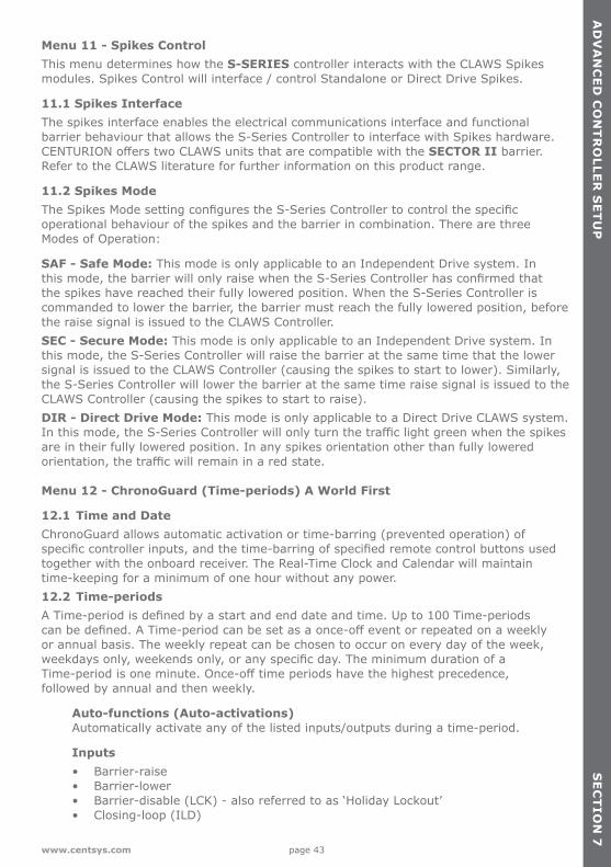
Menu 11 - Spikes ControlThis menu determines how the S-SERIES controller interacts with the CLAWS Spikesmodules. Spikes Control will interface / control Standalone or Direct Drive Spikes.
11.1 Spikes Interface The spikes interface enables the electrical communications interface and functional barrier behaviour that allows the S-Series Controller to interface with Spikes hardware. CENTURION offers two CLAWS units that are compatible with the SECTOR II barrier.Refer to the CLAWS literature for further information on this product range.
11.2 Spikes ModeThe Spikes Mode setting configures the S-Series Controller to control the specific operational behaviour of the spikes and the barrier in combination. There are three Modes of Operation:
SAF - Safe Mode: This mode is only applicable to an Independent Drive system. In this mode, the barrier will only raise when the S-Series Controller has confirmed that the spikes have reached their fully lowered position. When the S-Series Controller is commanded to lower the barrier, the barrier must reach the fully lowered position, before the raise signal is issued to the CLAWS Controller.SEC - Secure Mode: This mode is only applicable to an Independent Drive system. In this mode, the S-Series Controller will raise the barrier at the same time that the lower signal is issued to the CLAWS Controller (causing the spikes to start to lower). Similarly, the S-Series Controller will lower the barrier at the same time raise signal is issued to the CLAWS Controller (causing the spikes to start to raise).DIR - Direct Drive Mode: This mode is only applicable to a Direct Drive CLAWS system. In this mode, the S-Series Controller will only turn the traffic light green when the spikes are in their fully lowered position. In any spikes orientation other than fully lowered orientation, the traffic will remain in a red state.
Menu 12 - ChronoGuard (Time-periods) A World First
12.1 Time and DateChronoGuard allows automatic activation or time-barring (prevented operation) of specific controller inputs, and the time-barring of specified remote control buttons used together with the onboard receiver. The Real-Time Clock and Calendar will maintain time-keeping for a minimum of one hour without any power.12.2 Time-periodsA Time-period is defined by a start and end date and time. Up to 100 Time-periods can be defined. A Time-period can be set as a once-off event or repeated on a weekly or annual basis. The weekly repeat can be chosen to occur on every day of the week, weekdays only, weekends only, or any specific day. The minimum duration of a Time-period is one minute. Once-off time periods have the highest precedence, followed by annual and then weekly.
Auto-functions (Auto-activations) Automatically activate any of the listed inputs/outputs during a time-period.
Inputs • Barrier-raise • Barrier-lower • Barrier-disable (LCK) - also referred to as ‘Holiday Lockout’ • Closing-loop (ILD)
AD
VA
NC
ED
CO
NT
RO
LLE
R S
ET
UP
AD
VA
NC
ED
CO
NT
RO
LLER
SE
TU
PS
EC
TIO
N 7
page 44 www.centsys.com
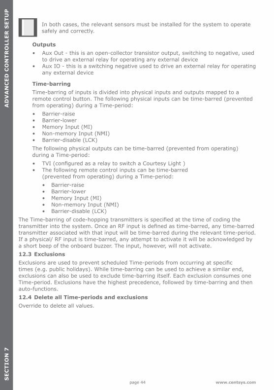
Outputs • Aux Out - this is an open-collector transistor output, switching to negative, used to drive an external relay for operating any external device • Aux IO - this is a switching negative used to drive an external relay for operating any external device
Time-barring Time-barring of inputs is divided into physical inputs and outputs mapped to a remote control button. The following physical inputs can be time-barred (prevented from operating) during a Time-period: • Barrier-raise • Barrier-lower • Memory Input (MI) • Non-memory Input (NMI) • Barrier-disable (LCK) The following physical outputs can be time-barred (prevented from operating) during a Time-period: • TVI (configured as a relay to switch a Courtesy Light ) • The following remote control inputs can be time-barred (prevented from operating) during a Time-period:
• Barrier-raise• Barrier-lower• Memory Input (MI)• Non-memory Input (NMI)• Barrier-disable (LCK)
The Time-barring of code-hopping transmitters is specified at the time of coding the transmitter into the system. Once an RF input is defined as time-barred, any time-barred transmitter associated with that input will be time-barred during the relevant time-period. If a physical/ RF input is time-barred, any attempt to activate it will be acknowledged by a short beep of the onboard buzzer. The input, however, will not activate.12.3 ExclusionsExclusions are used to prevent scheduled Time-periods from occurring at specific times (e.g. public holidays). While time-barring can be used to achieve a similar end, exclusions can also be used to exclude time-barring itself. Each exclusion consumes one Time-period. Exclusions have the highest precedence, followed by time-barring and then auto-functions.12.4 Delete all Time-periods and exclusionsOverride to delete all values.
AD
VA
NC
ED
CO
NT
RO
LLER
SE
TU
PS
EC
TIO
N 7
SE
CT
ION
7A
DV
AN
CE
D C
ON
TR
OLL
ER
SE
TU
P
In both cases, the relevant sensors must be installed for the system to operate safely and correctly.
page 45www.centsys.com
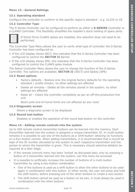
Menu 13 - General Settings
13.1 Operating standardConfigure the controller to conform to the specific region’s standard - e.g. UL325 or CE.13.2 Controller TypeThe S-Series Controller can be configured to perform as either a S-SERIES Controller or a CLAWS Controller. This flexibility simplifies the installer's stock holding of spare parts.
If Direct Drive CLAWS spikes are installed, this selection does not need to be performed.
The Controller Type Menu allows the user to verify what type of controller the S-Series Controller has been configured as.• If the LCD display shows SECT, this indicates that the S-Series Controller has been
configured to control the SECTOR II Barrier• If the LCD display shows SPK, this indicates that the S-Series Controller has been
configured to control the CLAWS spike moduleThe Select Controller Menu allows the user to change the function of the S-Series Controller. Two options are available; SECTOR II (SECT) and Spikes (SPK)13.3 Reset options • Factory defaults - Restore only the original factory defaults for the operating standard / profile chosen; no other settings are affected • Delete all remotes - Delete all the remotes stored in the system; no other settings are affected • Reset all – Clears the controller completely as per an off-the-production-line unit Boompoleend-of-travellimitsarenotaffectedbyanyreset13.4 Diagnostic screen Allows a diagnostic screen to be displayed.13.5 Round test button Disables or enables the operation of the round test-button on the controller
Menu 14 - Adding remote controls into the systemUp to 500 remote control transmitter buttons can be learned into the memory. Each transmitter learned into the system is assigned a unique transmitter ID. In multi-button remotes it is possible to use one of the buttons as a ‘shift-button’ allowing six functions on a four-button remote. When adding transmitters, it is recommended that a record be kept of the ID number allocated by the system to each respective transmitter and the person to whom the transmitter is given. This is necessary should selective deletion be required at a later stage.• If the remote controls menu has been ‘locked’ as discussed later, only by pressing a
button of a transmitter learned into the system, can this menu be accessed• It is possible to artificially increase the number of buttons of a multi-button
transmitter by using a two-button combination• One of the buttons is used as a shift button to allow the other buttons to be used again in combination with this button. In other words, the user will press and hold the shift button, before pressing one of the other buttons to create a new button• The shift button cannot be used as a button on its own, it must always be used in combination with the other buttons
AD
VA
NC
ED
CO
NT
RO
LLER
SE
TU
PS
EC
TIO
N 7
page 46 www.centsys.com
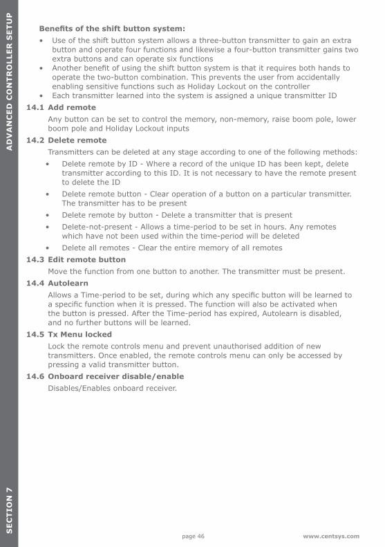
Benefits of the shift button system: • Use of the shift button system allows a three-button transmitter to gain an extra button and operate four functions and likewise a four-button transmitter gains two extra buttons and can operate six functions • Another benefit of using the shift button system is that it requires both hands to operate the two-button combination. This prevents the user from accidentally enabling sensitive functions such as Holiday Lockout on the controller • Each transmitter learned into the system is assigned a unique transmitter ID14.1 Add remote Any button can be set to control the memory, non-memory, raise boom pole, lower boom pole and Holiday Lockout inputs14.2 Delete remote Transmitters can be deleted at any stage according to one of the following methods:
• Delete remote by ID - Where a record of the unique ID has been kept, delete transmitter according to this ID. It is not necessary to have the remote present to delete the ID
• Delete remote button - Clear operation of a button on a particular transmitter. The transmitter has to be present
• Delete remote by button - Delete a transmitter that is present• Delete-not-present - Allows a time-period to be set in hours. Any remotes
which have not been used within the time-period will be deleted• Delete all remotes - Clear the entire memory of all remotes
14.3 Edit remote button Move the function from one button to another. The transmitter must be present.14.4 Autolearn Allows a Time-period to be set, during which any specific button will be learned to a specific function when it is pressed. The function will also be activated when the button is pressed. After the Time-period has expired, Autolearn is disabled, and no further buttons will be learned.14.5 Tx Menu locked Lock the remote controls menu and prevent unauthorised addition of new transmitters. Once enabled, the remote controls menu can only be accessed by pressing a valid transmitter button.14.6 Onboard receiver disable/enable Disables/Enables onboard receiver.
AD
VA
NC
ED
CO
NT
RO
LLER
SE
TU
PS
EC
TIO
N 7
SE
CT
ION
7A
DV
AN
CE
D C
ON
TR
OLL
ER
SE
TU
P
page 47www.centsys.com
8. Maintenance
Maintenance should be carried out at regular intervals. The list below can be used as a schedule for maintenance procedures.As a minimum, the following maintenance procedures should be performed on a basis that is consistent with the daily usage of the unit:1. Tighten the two holding-down nuts.2. Tighten the nuts holding the pole to the boom-coupler.3. Check the boom pole level, and adjust if necessary using the level-adjustment-link
(refer to Section 3.2).4. Tighten the lock-nuts on the level-adjustment-link.5. Check the spring tension, and adjust if necessary. A diagnostic screen indicating how
many turns of the adjustment link is necessary, and in which direction, is provided on the controller (Refer to Section 5).
Special maintenance for Grade 316 Stainless steel barriersOxidation in marine and coastal areas may result in brown discolouration (‘tea staining’) of the barrier housing and, while this does not impact the structural integrity of the barrier adversely, it is unattractive and can be easily prevented by regularly washing the barrier-housing with a soft cloth and warm water. A mild detergent may also be used. This will remove salt and other corrosive materials from the housing and retain the attractive sheen of the stainless steel.
MA
INT
EN
AN
CE
SE
CT
ION
8
page 48 www.centsys.com
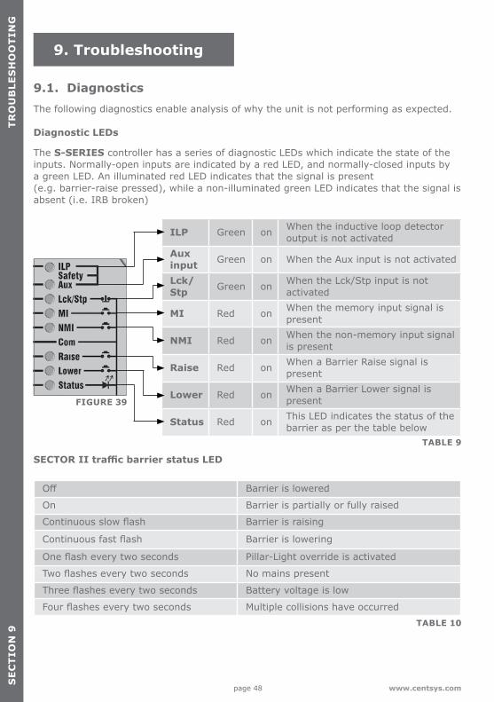
9.1. DiagnosticsThe following diagnostics enable analysis of why the unit is not performing as expected.
Diagnostic LEDs
The S-SERIES controller has a series of diagnostic LEDs which indicate the state of the inputs. Normally-open inputs are indicated by a red LED, and normally-closed inputs by a green LED. An illuminated red LED indicates that the signal is present (e.g. barrier-raise pressed), while a non-illuminated green LED indicates that the signal is absent (i.e. IRB broken)
SECTOR II traffic barrier status LED
9. Troubleshooting
ILP Green on When the inductive loop detector output is not activated
Aux input Green on When the Aux input is not activated
Lck/Stp Green on When the Lck/Stp input is not
activated
MI Red on When the memory input signal is present
NMI Red on When the non-memory input signal is present
Raise Red on When a Barrier Raise signal is present
Lower Red on When a Barrier Lower signal is present
Status Red on This LED indicates the status of the barrier as per the table below
Off Barrier is lowered
On Barrier is partially or fully raised
Continuous slow flash Barrier is raising
Continuous fast flash Barrier is lowering
One flash every two seconds Pillar-Light override is activated
Two flashes every two seconds No mains present
Three flashes every two seconds Battery voltage is low
Four flashes every two seconds Multiple collisions have occurred
FIGURE 39
TABLE 9
TABLE 10
SE
CT
ION
9T
RO
UB
LES
HO
OT
ING
page 49www.centsys.com
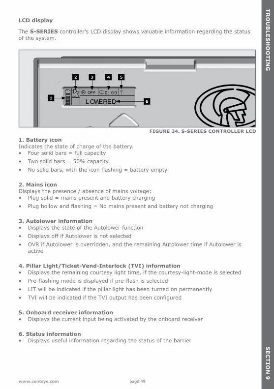
LCD display
The S-SERIES controller’s LCD display shows valuable information regarding the status of the system.
1. Battery iconIndicates the state of charge of the battery. • Four solid bars = full capacity• Two solid bars = 50% capacity• No solid bars, with the icon flashing = battery empty
2. Mains iconDisplays the presence / absence of mains voltage: • Plug solid = mains present and battery charging • Plug hollow and flashing = No mains present and battery not charging
3. Autolower information • Displays the state of the Autolower function • Displays off if Autolower is not selected• OVR if Autolower is overridden, and the remaining Autolower time if Autolower is
active
4. Pillar Light/Ticket-Vend-Interlock (TVI) information • Displays the remaining courtesy light time, if the courtesy-light-mode is selected • Pre-flashing mode is displayed if pre-flash is selected• LIT will be indicated if the pillar light has been turned on permanently• TVI will be indicated if the TVI output has been configured
5. Onboard receiver information• Displays the current input being activated by the onboard receiver
6. Status information• Displays useful information regarding the status of the barrier
FIGURE 34. S-SERIES CONTROLLER LCD
OFF 0:00
LOWERED
5
6
42 3
1
TR
OU
BLE
SH
OO
TIN
GS
EC
TIO
N 9
page 50 www.centsys.com
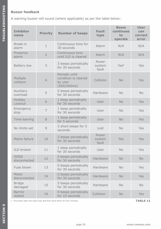
Buzzer feedback
A warning buzzer will sound (where applicable) as per the table below:
1. The boom pole will close fully and then shut down for two minutes
Inhibitor name Priority Number of beeps Fault
type
Boom continues
to operate
User can
correct error
Break-in alarm 1 Continuous tone for
30 seconds Alarm N/A N/A
Presence alarm 2 Continuous tone
until ILD is cleared Alarm N/A N/A
Battery low 3 3 beeps periodically for 30 seconds
Power system fault
Yes1 Yes
Multiple collision 4
Periodic until condition is cleared by user (500/500ms)
Collision No Yes
Auxiliary overload 5 5 beeps periodically
for 30 seconds Hardware No No
Holiday Lockout 6 1 beep periodically
for 30 seconds User No Yes
Emergency stop 7 1 beep periodically
for 30 seconds User No Yes
Time-barring 8 1 beep periodically for 5 seconds User No Yes
No limits set 9 3 short beeps for 5 seconds Lost No Yes
Mains failure 10 2 beeps periodically for 30 seconds
Power system fault
Yes Yes
ILD broken 11 1 beep periodically for 30 seconds User No Yes
DOSS disconnected 12 5 beeps periodically
for 30 seconds Hardware No No
Fuse blown 13 5 beeps periodically for 30 seconds Hardware No Yes
Motor disconnected 14 5 beeps periodically
for 30 seconds Hardware No Yes
Bridge damaged 15 5 beeps periodically
for 30 seconds Hardware No No
Barrier stalled 16 4 beeps periodically
for 10 seconds Collision No Yes
TABLE 11
SE
CT
ION
9T
RO
UB
LES
HO
OT
ING

page 51www.centsys.com
10. Appendices
10.1. Appendix 1. SECTOR II specifications10.1.1. Unit specifications
Depending on the site, the user will need to decide on what type of barrier is most suitable. Table 12 shows the specifications of the various units. Please note that the operator type and speed varies based on the chosen pole length.
SECTOR II traffic barrier 3 Metre8 4.5 Metre8 6 Metre8
Input voltage 90 - 240V AC ±10%, 50 Hz1
Motor voltage 12V DCMotor power supply Battery-driven (standard capacity - 7 Ah)2
Battery charger CP84SM – 1.8A @ 13.8VCurrent consumption (Mains) 170mABoom pole length 3.0M 4.5M 6.0MBoom pole raise time (adjustable)3 1.2 Sec 3 Sec 3 Sec
Manual override 6mm Allen key-operated from outside of the unitMaximum number of operations per day 3000
Duty cycle - mains present4 5 80%Operations in standby with 7Ah batteryHalf day6 Full day6
30007 30007
Collision sensing ElectronicOperating temperature range -20°C to 55°CReceiver code storage capacity 500 Transmitter buttons
Receiver frequency 433.92 MHz 1. Can operate off a solar supply, consult Centurion Systems (Pty) Ltd for assistance2. Battery capacity can be increased for longer standby times. (Battery capacity </=33Ah unless charger is upgraded)3. Boom-pole raise and lower-times are both individually configurable to suit individual installation requirements4. Based on 25°C ambient temperature and unit not in direct sunlight5. Based on an output torque of less than 50% of rated torque6. Based on basic operator excluding closing-loop detector7. Limited by daily usage8. The model designation of the barrier is an indication of the maximum length of pole for the specific spring. In other words, SECTOR II 3m = maximum 3m pole; SECTOR II 4.5m = maximum 4.5m pole, etc. In other words, if you wish to fit a 4.5m pole, a SECTOR II 4.5m/6m with corresponding spring must be used.
TABLE 12
AP
PE
ND
ICE
SS
EC
TIO
N 1
0
page 52 www.centsys.com
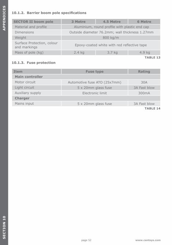
10.1.2. Barrier boom pole specifications
10.1.3. Fuse protection
SECTOR II boom pole 3 Metre 4.5 Metre 6 MetreMaterial and profile Aluminium, round profile with plastic end capDimensions Outside diameter 76.2mm; wall thickness 1.27mmWeight 800 kg/mSurface Protection, colour and markings Epoxy-coated white with red reflective tape
Mass of pole (kg) 2.4 kg 3.7 kg 4.9 kg
Item Fuse type RatingMain controllerMotor circuit Automotive fuse ATO (25x7mm) 30ALight circuit 5 x 20mm glass fuse 3A Fast blowAuxiliary supply Electronic limit 300mAChargerMains input 5 x 20mm glass fuse 3A Fast blow
TABLE 13
TABLE 14
SE
CT
ION
10
AP
PE
ND
ICE
S

page 53www.centsys.com
10.1.4. Certificate of compliance
This page has been left blank intensionally
AP
PE
ND
ICE
SS
EC
TIO
N 1
0
page 54 www.centsys.com
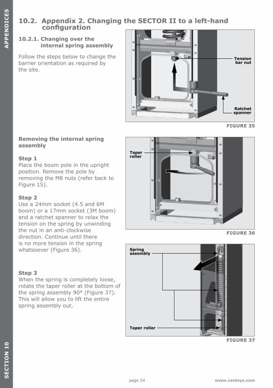
10.2. Appendix 2. Changing the SECTOR II to a left-hand configuration10.2.1. Changing over the
internal spring assembly
Follow the steps below to change the barrier orientation as required by the site.
Removing the internal spring assembly
Step 1 Place the boom pole in the upright position. Remove the pole by removing the M8 nuts (refer back to Figure 15).
Step 2 Use a 24mm socket (4.5 and 6M boom) or a 17mm socket (3M boom) and a ratchet spanner to relax the tension on the spring by unwinding the nut in an anti-clockwise direction. Continue until there is no more tension in the spring whatsoever (Figure 36).
Step 3 When the spring is completely loose, rotate the taper roller at the bottom of the spring assembly 90° (Figure 37). This will allow you to lift the entire spring assembly out.
FIGURE 35
FIGURE 36
FIGURE 37
Tension bar nut
Ratchet spanner
Taper roller
Spring assembly
Taper roller
SE
CT
ION
10
AP
PE
ND
ICE
S
page 55www.centsys.com
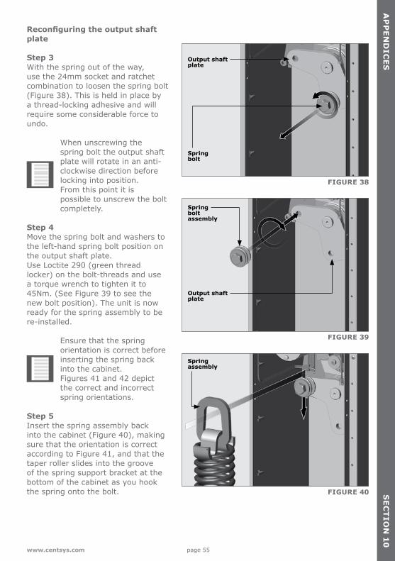
Reconfiguring the output shaft plate
Step 3 With the spring out of the way, use the 24mm socket and ratchet combination to loosen the spring bolt (Figure 38). This is held in place by a thread-locking adhesive and will require some considerable force to undo.
When unscrewing the spring bolt the output shaft plate will rotate in an anti-clockwise direction before locking into position. From this point it is possible to unscrew the bolt completely.
Step 4 Move the spring bolt and washers to the left-hand spring bolt position on the output shaft plate. Use Loctite 290 (green thread locker) on the bolt-threads and use a torque wrench to tighten it to 45Nm. (See Figure 39 to see the new bolt position). The unit is now ready for the spring assembly to be re-installed.
Ensure that the spring orientation is correct before inserting the spring back into the cabinet. Figures 41 and 42 depict the correct and incorrect spring orientations.
Step 5 Insert the spring assembly back into the cabinet (Figure 40), making sure that the orientation is correct according to Figure 41, and that the taper roller slides into the groove of the spring support bracket at the bottom of the cabinet as you hook the spring onto the bolt.
FIGURE 38
FIGURE 39
FIGURE 40
Spring assembly
Spring bolt
Spring boltassembly
Output shaft plate
Output shaft plate
AP
PE
ND
ICE
SS
EC
TIO
N 1
0
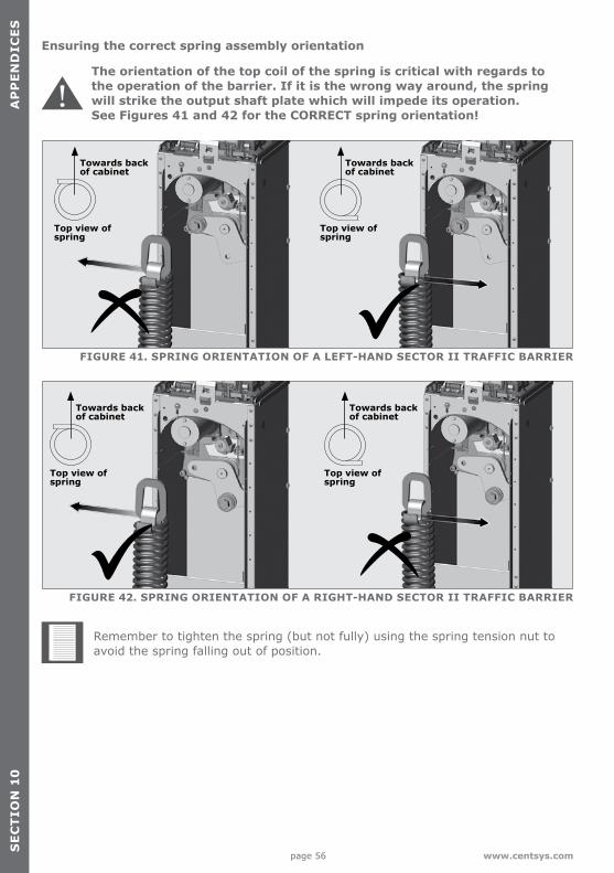
page 56 www.centsys.com
FIGURE 41. SPRING ORIENTATION OF A LEFT-HAND SECTOR II TRAFFIC BARRIER
FIGURE 42. SPRING ORIENTATION OF A RIGHT-HAND SECTOR II TRAFFIC BARRIER
Top view of spring
Top view of spring
Top view of spring
Top view of spring
Towards back of cabinet
Towards back of cabinet
Towards back of cabinet
Towards back of cabinet
Ensuring the correct spring assembly orientation
The orientation of the top coil of the spring is critical with regards to the operation of the barrier. If it is the wrong way around, the spring will strike the output shaft plate which will impede its operation. See Figures 41 and 42 for the CORRECT spring orientation!
Remember to tighten the spring (but not fully) using the spring tension nut to avoid the spring falling out of position.
SE
CT
ION
10
AP
PE
ND
ICE
S
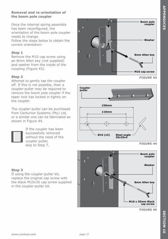
page 57www.centsys.com
Removal and re-orientation of the boom pole coupler
Once the internal spring assembly has been reconfigured, the orientation of the boom pole coupler needs to change. Follow the steps below to obtain the correct orientation:
Step 1 Remove the M10 cap screw using an 8mm Allen key (not supplied) and washer from the inside of the coupling (Figure 43). Step 2 Attempt to gently tap the coupler off. If this is not possible, then a coupler-puller may be required to remove the boom pole coupler if the taper lock has locked in tightly on the coupler. The coupler-puller can be purchased from Centurion Systems (Pty) Ltd, or a similar one can be fabricated as shown in Figure 44.
If the coupler has been successfully removed without the need of the coupler puller, skip to Step 7.
Step 3 If using the coupler-puller kit, replace the original cap screw with the black M10x35 cap screw supplied in the coupler-puller kit.
FIGURE 43
FIGURE 44
FIGURE 45
150mm
110mm
Ø10 (x3) Steel angle25x25x4
Boom pole coupler
Coupler puller
Washer
8mm Allen key
M10 cap screw
Boom pole coupler
Washer
8mm Allen key
M10 x 35mm Black cap screw
AP
PE
ND
ICE
SS
EC
TIO
N 1
0
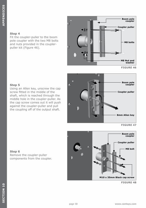
page 58 www.centsys.com
Step 4 Fit the coupler-puller to the boom pole coupler with the two M8 bolts and nuts provided in the coupler-puller kit (Figure 46).
Step 5 Using an Allen key, unscrew the cap screw fitted in the middle of the shaft, which is reached through the middle hole in the coupler-puller. As the cap screw comes out it will push against the coupler-puller and pull the coupling off of the output shaft.
Step 6 Remove the coupler-puller components from the coupler.
FIGURE 46
FIGURE 47
FIGURE 48
Boom pole coupler
Boom pole coupler
Boom pole coupler
Coupler puller
Coupler puller
Coupler puller
M8 Nut and washer
M8 bolts
M8 bolt
M10 x 35mm Black cap screw
8mm Allen key
SE
CT
ION
10
AP
PE
ND
ICE
S
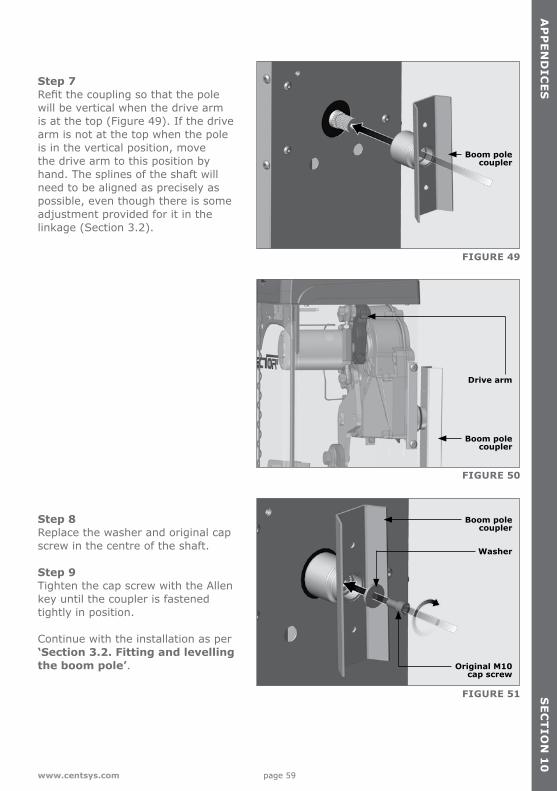
page 59www.centsys.com
Step 7 Refit the coupling so that the pole will be vertical when the drive arm is at the top (Figure 49). If the drive arm is not at the top when the pole is in the vertical position, move the drive arm to this position by hand. The splines of the shaft will need to be aligned as precisely as possible, even though there is some adjustment provided for it in the linkage (Section 3.2).
Step 8 Replace the washer and original cap screw in the centre of the shaft.
Step 9 Tighten the cap screw with the Allen key until the coupler is fastened tightly in position.
Continue with the installation as per ‘Section 3.2. Fitting and levelling the boom pole’.
FIGURE 49
FIGURE 50
FIGURE 51
Boom pole coupler
Boom pole coupler
Boom pole coupler
Washer
Drive arm
Original M10 cap screw
AP
PE
ND
ICE
SS
EC
TIO
N 1
0
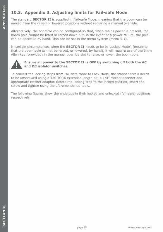
page 60 www.centsys.com
10.3. Appendix 3. Adjusting limits for Fail-safe ModeThe standard SECTOR II is supplied in Fail-safe Mode, meaning that the boom can be moved from the raised or lowered positions without requiring a manual override.
Alternatively, the operator can be configured so that, when mains power is present, the boom pole cannot be lifted or forced down but, in the event of a power-failure, the pole can be operated by hand. This can be set in the menu system (Menu 5.1).
In certain circumstances when the SECTOR II needs to be in ‘Locked Mode’, (meaning that the boom pole cannot be raised, or lowered, by hand), it will require use of the 6mm Allen key (provided) in the manual override slot to raise, or lower, the boom pole.
Ensure all power to the SECTOR II is OFF by switching off both the AC and DC isolator switches.
To convert the locking stops from Fail-safe Mode to Lock Mode, the stopper screw needs to be unscrewed using a T30 TORX extended length bit, a 1/4” ratchet spanner and appropriate ratchet adaptor. Rotate the locking stop to the locked position, insert the screw and tighten using the aforementioned tools.
The following figures show the endstops in their locked and unlocked (fail-safe) positions respectively.
SE
CT
ION
10
AP
PE
ND
ICE
S
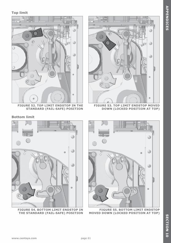
page 61www.centsys.com
Top limit
Bottom limit
FIGURE 52. TOP LIMIT ENDSTOP IN THE STANDARD (FAIL-SAFE) POSITION
FIGURE 54. BOTTOM LIMIT ENDSTOP IN THE STANDARD (FAIL-SAFE) POSITION
FIGURE 53. TOP LIMIT ENDSTOP MOVED DOWN (LOCKED POSITION AT TOP)
FIGURE 55. BOTTOM LIMIT ENDSTOP MOVED DOWN (LOCKED POSITION AT TOP)
AP
PE
ND
ICE
SS
EC
TIO
N 1
0
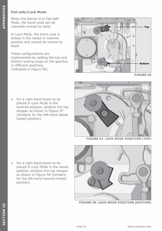
page 62 www.centsys.com
Fail-safe/Lock Mode
When the barrier is in Fail-safe Mode, the boom pole can be manually moved by hand.
In Lock Mode, the boom pole is locked in the raised or lowered position and cannot be moved by hand.
These configurations are implemented by setting the top and bottom locking stops on the gearbox in different positions. (indicated in Figure 56)
• For a right-hand boom to be placed in Lock Mode in the lowered position, position the top stopper as shown in Figure 57 (similarly for the left-hand raised locked position)
• For a right-hand boom to be placed in Lock Mode in the raised position, position the top stopper as shown in Figure 58 (similarly for the left-hand lowered locked position)
FIGURE 56
FIGURE 57. LOCK MODE POSITION (TOP)
FIGURE 58. LOCK MODE POSITION (BOTTOM)
Top
Bottom
SE
CT
ION
10
AP
PE
ND
ICE
S
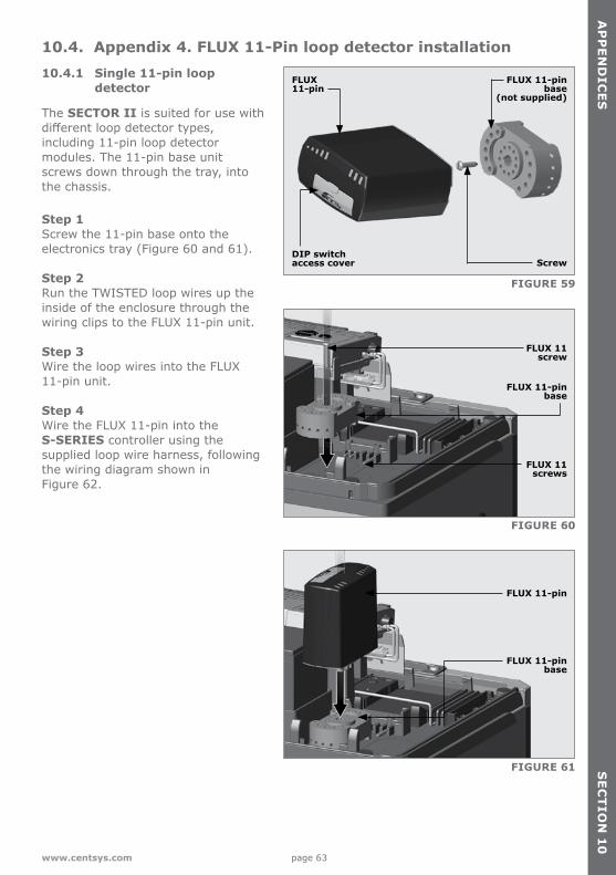
page 63www.centsys.com
10.4. Appendix 4. FLUX 11-Pin loop detector installation10.4.1 Single 11-pin loop
detector
The SECTOR II is suited for use with different loop detector types, including 11-pin loop detector modules. The 11-pin base unit screws down through the tray, into the chassis.
Step 1 Screw the 11-pin base onto the electronics tray (Figure 60 and 61).
Step 2 Run the TWISTED loop wires up the inside of the enclosure through the wiring clips to the FLUX 11-pin unit.
Step 3 Wire the loop wires into the FLUX 11-pin unit.
Step 4 Wire the FLUX 11-pin into the S-SERIES controller using the supplied loop wire harness, following the wiring diagram shown in Figure 62.
FIGURE 59
FIGURE 60
FIGURE 61
DIP switchaccess cover
FLUX 11-pin base
(not supplied)
FLUX 11-pin base
FLUX 11-pin base
FLUX 11-pin
Screw
FLUX 11 screw
FLUX 11-pin
AP
PE
ND
ICE
SS
EC
TIO
N 1
0
FLUX 11 screws
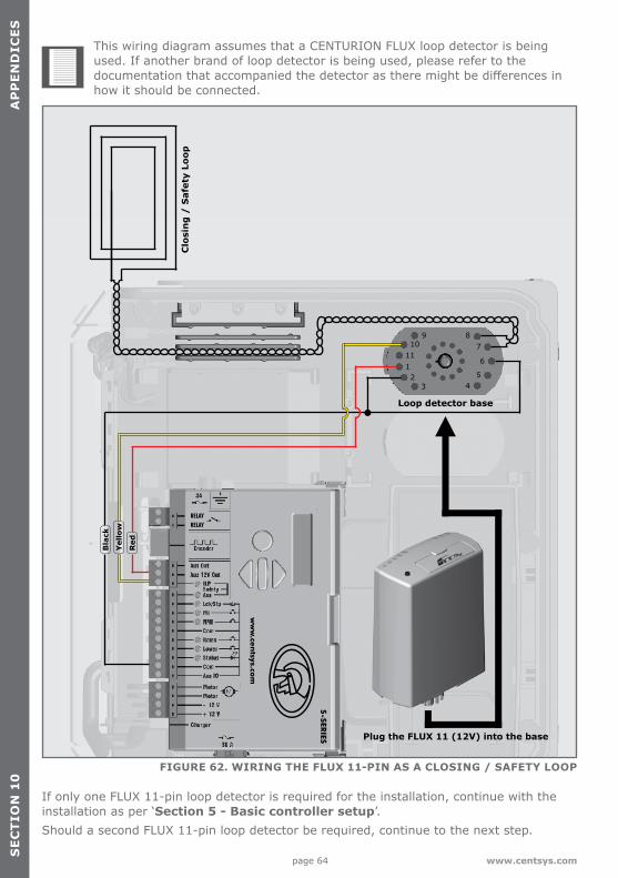
page 64 www.centsys.com
FIGURE 62. WIRING THE FLUX 11-PIN AS A CLOSING / SAFETY LOOP
Clo
sin
g /
Saf
ety
Loop
Loop detector base
Plug the FLUX 11 (12V) into the base
If only one FLUX 11-pin loop detector is required for the installation, continue with the installation as per ‘Section 5 - Basic controller setup’.Should a second FLUX 11-pin loop detector be required, continue to the next step.
SE
CT
ION
10
AP
PE
ND
ICE
S
Bla
ck
Red
Yel
low
This wiring diagram assumes that a CENTURION FLUX loop detector is being used. If another brand of loop detector is being used, please refer to the documentation that accompanied the detector as there might be differences in how it should be connected.
ww
w.ce
ntsys.co
m
RELAYRELAY
S-SER
IES
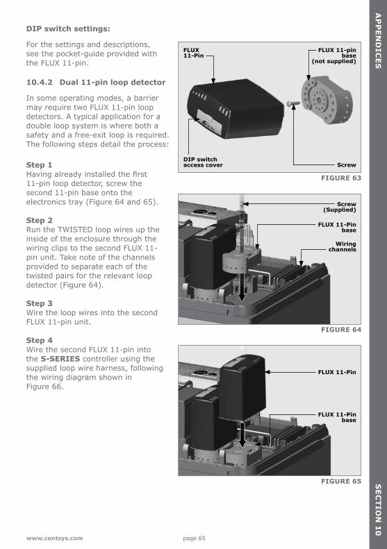
page 65www.centsys.com
10.4.2 Dual 11-pin loop detector
In some operating modes, a barrier may require two FLUX 11-pin loop detectors. A typical application for a double loop system is where both a safety and a free-exit loop is required. The following steps detail the process:
Step 1 Having already installed the first 11-pin loop detector, screw the second 11-pin base onto the electronics tray (Figure 64 and 65).
Step 2 Run the TWISTED loop wires up the inside of the enclosure through the wiring clips to the second FLUX 11-pin unit. Take note of the channels provided to separate each of the twisted pairs for the relevant loop detector (Figure 64).
Step 3 Wire the loop wires into the second FLUX 11-pin unit.
Step 4 Wire the second FLUX 11-pin into the S-SERIES controller using the supplied loop wire harness, following the wiring diagram shown in Figure 66.
FIGURE 63
FIGURE 64
FIGURE 65
DIP switchaccess cover
FLUX 11-Pin base
Wiring channels
FLUX 11-Pin base
FLUX 11-Pin
Screw
Screw(Supplied)
FLUX 11-Pin
AP
PE
ND
ICE
SS
EC
TIO
N 1
0
FLUX 11-pin base
(not supplied)
DIP switch settings:
For the settings and descriptions, see the pocket-guide provided with the FLUX 11-pin.
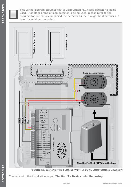
page 66 www.centsys.com
FIGURE 66. WIRING THE FLUX 11 WITH A DUAL LOOP CONFIGURATION
Free
-Exi
t Lo
op
Clo
sin
g /
Saf
ety
Loop
Loop detector bases
Continue with the installation as per ‘Section 5 - Basic controller setup’.
SE
CT
ION
10
AP
PE
ND
ICE
S
Red
Wh
ite
Bla
ck
Yel
low
This wiring diagram assumes that a CENTURION FLUX loop detector is being used. If another brand of loop detector is being used, please refer to the documentation that accompanied the detector as there might be differences in how it should be connected.
Plug the FLUX 11 (12V) into the base
ww
w.ce
ntsys.co
m
RELAYRELAY
S-SER
IES
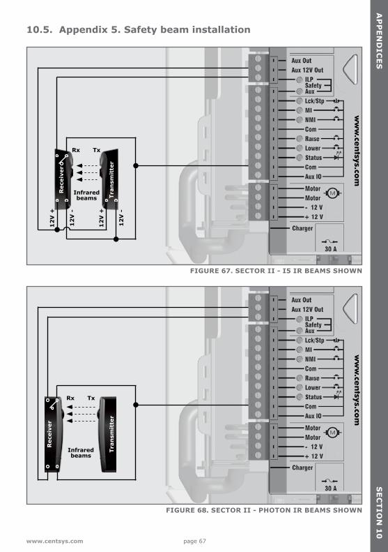
page 67www.centsys.com
10.5. Appendix 5. Safety beam installation
12
V +
12
V +
12
V -
12
V -
Rec
eive
r
Tran
smit
ter
Infraredbeams
Infraredbeams
Rx
Rx
Tx
Tx
FIGURE 67. SECTOR II - I5 IR BEAMS SHOWN
FIGURE 68. SECTOR II - PHOTON IR BEAMS SHOWN
Rec
eive
r
Tran
smit
ter
AP
PE
ND
ICE
SS
EC
TIO
N 1
0
ww
w.ce
ntsys.co
mw
ww
.cen
tsys.com
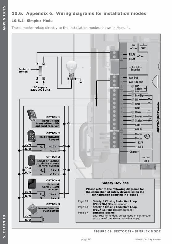
page 68 www.centsys.com
10.6. Appendix 6. Wiring diagrams for installation modes10.6.1. Simplex Mode
These modes relate directly to the installation modes shown in Menu 4.
FIGURE 69. SECTOR II - SIMPLEX MODE
1 2abc
3abc
3Efg
4Hij
5klm
6nop
7qrs
8tuv
9wxvz
10* #
1 2abc
3abc
3Efg
4Hij
5klm
6nop
7qrs
8tuv
9wxvz
10* #
1 2abc
3abc
3Efg
4Hij
5klm
6nop
7qrs
8tuv
9wxvz
10* #
1 2abc
3abc
3Efg
4Hij
5klm
6nop
7qrs
8tuv
9wxvz
10* #1 2abc
3abc
3Efg
4Hij
5klm
6nop
7qrs
8tuv
9wxvz
10* #
OPTION 1
OPTION 2
OPTION 3
OPTION 4
OPTION 5
CENTURIONtransmitter with onboard receiver
SMARTGUARDkeypad
SOLO or Latticeproximity access
control system
ExternalCENTURION
receiver
Normally-openPushbutton
COM+12V
+12V
+12V
-12V
-12V
-12V
N/O
COMN/O
COMN/O
COMN/O
1 2abc
3abc
3Efg
4Hij
5klm
6nop
7qrs
8tuv
9wxvz
10* #
AC supply 220V AC 50HZ
Isolatorswitch
Safety Devices
Please refer to the following diagrams for the connection of safety devices using the
configuration depicted in Figure 1
Page 19 Safety / Closing Inductive Loop (FLUX SA) (Recommended)Page 63 Safety / Closing Inductive Loop (FLUX 11 Pin) (Recommended)Page 67 Infrared Beams (Not recommended, unless used in conjunction with one of the above inductive loops)
SE
CT
ION
10
AP
PE
ND
ICE
S
ww
w.ce
ntsys.co
m
RELAYRELAY
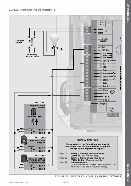
page 69www.centsys.com
10.6.2. Complex Mode (Option 1)
FIGURE 70. SECTOR II - COMPLEX MODE (OPTION 1)
1 2abc
3abc
3Efg
4Hij
5klm
6nop
7qrs
8tuv
9wxvz
10* #
AC supply 220V AC 50HZ
Safety Devices
Please refer to the following diagrams for the connection of safety devices using the
configuration depicted in Figure 1
Page 19 Safety / Closing Inductive Loop (FLUX SA) (Recommended)Page 63 Safety / Closing Inductive Loop (FLUX 11 Pin) (Recommended)Page 67 Infrared Beams (Not recommended, unless used in conjunction with one of the above inductive loops)
1 2abc
3abc
3Efg
4Hij
5klm
6nop
7qrs
8tuv
9wxvz
10* #
1 2abc
3abc
3Efg
4Hij
5klm
6nop
7qrs
8tuv
9wxvz
10* #
OPTION 2
OPTION 1
OPTION 3
SMARTGUARDkeypad
SOLO or Latticeproximity access
control system
Memory Input
Magnetic card reader
COM
COM
N/O
N/O
COMN/O
MA
G-C
ARD
+12V
+12V
+12V
-12V
-12V
-12V
Isolatorswitch
AP
PE
ND
ICE
SS
EC
TIO
N 1
0
ww
w.ce
ntsys.co
m
RELAYRELAY
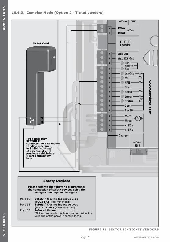
page 70 www.centsys.com
10.6.3. Complex Mode (Option 2 - Ticket vendors)
FIGURE 71. SECTOR II - TICKET VENDORS
Ticket Vend
Safety Devices
Please refer to the following diagrams for the connection of safety devices using the
configuration depicted in Figure 1
TVI signal from SECTOR II connected to a ticket vending machine to inhibit ‘spitting’ of new ticket until previous vehicle has cleared the safety loop
Page 19 Safety / Closing Inductive Loop (FLUX SA) (Recommended)Page 63 Safety / Closing Inductive Loop (FLUX 11 Pin) (Recommended)Page 67 Infrared Beams (Not recommended, unless used in conjunction with one of the above inductive loops)
SE
CT
ION
10
AP
PE
ND
ICE
S
ww
w.ce
ntsys.co
m
RELAYRELAY
page 71www.centsys.com
10.6.4. Uni-directional traffic
The free-exit function allows vehicles to exit a facility by automatically raising the barrier. It is recommended that an inductive loop detector be used to activate the free-exit facility. Infrared beams can be used for this function but a loop detector is preferred.
The free-exit loop will raise the barrier and the closing loop will be used to lower the barrier the moment the vehicle has exited. Select the relevant direction on the control card within the loop detector menu, refer to Section 7.
10.6.5. Bi-directional traffic
This allows access for traffic from both directions in a single lane. In this case the same barrier provides access control for vehicles entering and free-exit for vehicles exiting. A triggering device can be used for the access function and the loop for the free-exit function.
The free-exit loop must be mounted close enough to the closing loop so that the vehicle exiting is still present on this loop when it reaches the closing loop. However, these must not be too close together (a distance greater than 1000mm is required), or magnetic interference will be caused.
The free-exit loop will raise the barrier and the closing loop will be used to lower the barrier the moment the vehicle has exited. Select the relevant direction on the control card within the Loop Detector Menu refer to Section 7.
AP
PE
ND
ICE
SS
EC
TIO
N 1
0
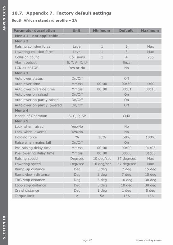
page 72 www.centsys.com
10.7. Appendix 7. Factory default settingsSouth African standard profile – ZA
Parameter description Unit Minimum Default MaximumMenu 1 - not applicableMenu 2Raising collision force Level 1 3 MaxLowering collision force Level 1 3 MaxCollision count Collisions 1 4 255Alarm output B, T, A, X, L1 BuzzLCK as ESTOP Yes or No NoMenu 3Autolower status On/Off OffAutolower time Mm:ss 00:00 00:30 4:00Autolower override time Mm:ss 00:00 00:01 00:15Autolower on raised On/Off OnAutolower on partly raised On/Off OnAutolower on partly lowered On/Off OffMenu 4Modes of Operation S, C, P, SP CMXMenu 5Lock when raised Yes/No NoLock when lowered Yes/No NoHolding force % 10% 50% 100%Raise when mains fail On/Off OnPre-raising delay time Mm:ss 00:00 00:00 01:05Pre-lowering delay time Mm:ss 00:00 00:00 01:05Raising speed Deg/sec 10 deg/sec 37 deg/sec MaxLowering speed Deg/sec 10 deg/sec 37 deg/sec MaxRamp-up distance Deg 3 deg 7 deg 15 degRamp-down distance Deg 3 deg 7 deg 15 degTRG stop distance Deg 5 deg 10 deg 30 degLoop stop distance Deg 5 deg 10 deg 30 degCrawl distance Deg 1 deg 1 deg 5 degTorque limit A 5A 15A 15A
SE
CT
ION
10
AP
PE
ND
ICE
S
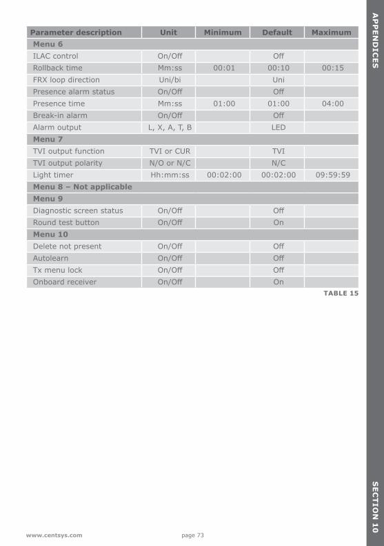
page 73www.centsys.com
Parameter description Unit Minimum Default MaximumMenu 6ILAC control On/Off OffRollback time Mm:ss 00:01 00:10 00:15FRX loop direction Uni/bi UniPresence alarm status On/Off OffPresence time Mm:ss 01:00 01:00 04:00Break-in alarm On/Off OffAlarm output L, X, A, T, B LEDMenu 7TVI output function TVI or CUR TVITVI output polarity N/O or N/C N/CLight timer Hh:mm:ss 00:02:00 00:02:00 09:59:59Menu 8 – Not applicableMenu 9Diagnostic screen status On/Off OffRound test button On/Off OnMenu 10Delete not present On/Off OffAutolearn On/Off OffTx menu lock On/Off OffOnboard receiver On/Off On
TABLE 15
AP
PE
ND
ICE
SS
EC
TIO
N 1
0
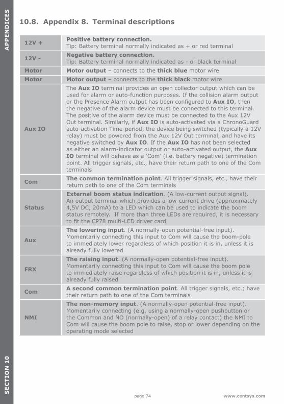
page 74 www.centsys.com
10.8. Appendix 8. Terminal descriptions
12V + Positive battery connection. Tip: Battery terminal normally indicated as + or red terminal
12V - Negative battery connection. Tip: Battery terminal normally indicated as - or black terminal
Motor Motor output – connects to the thick blue motor wireMotor Motor output – connects to the thick black motor wire
Aux IO
The Aux IO terminal provides an open collector output which can be used for alarm or auto-function purposes. If the collision alarm output or the Presence Alarm output has been configured to Aux IO, then the negative of the alarm device must be connected to this terminal. The positive of the alarm device must be connected to the Aux 12V Out terminal. Similarly, if Aux IO is auto-activated via a ChronoGuard auto-activation Time-period, the device being switched (typically a 12V relay) must be powered from the Aux 12V Out terminal, and have its negative switched by Aux IO. If the Aux IO has not been selected as either an alarm-indicator output or auto-activated output, the Aux IO terminal will behave as a ‘Com’ (i.e. battery negative) termination point. All trigger signals, etc., have their return path to one of the Com terminals
Com The common termination point. All trigger signals, etc., have their return path to one of the Com terminals
Status
External boom status indication. (A low-current output signal). An output terminal which provides a low-current drive (approximately 4,5V DC, 20mA) to a LED which can be used to indicate the boom status remotely. If more than three LEDs are required, it is necessary to fit the CP78 multi-LED driver card
Aux
The lowering input. (A normally-open potential-free input). Momentarily connecting this input to Com will cause the boom-pole to immediately lower regardless of which position it is in, unless it is already fully lowered
FRX
The raising input. (A normally-open potential-free input). Momentarily connecting this input to Com will cause the boom pole to immediately raise regardless of which position it is in, unless it is already fully raised
Com A second common termination point. All trigger signals, etc.; have their return path to one of the Com terminals
NMI
The non-memory input. (A normally-open potential-free input). Momentarily connecting (e.g. using a normally-open pushbutton or the Common and NO (normally-open) of a relay contact) the NMI to Com will cause the boom pole to raise, stop or lower depending on the operating mode selected
SE
CT
ION
10
AP
PE
ND
ICE
S
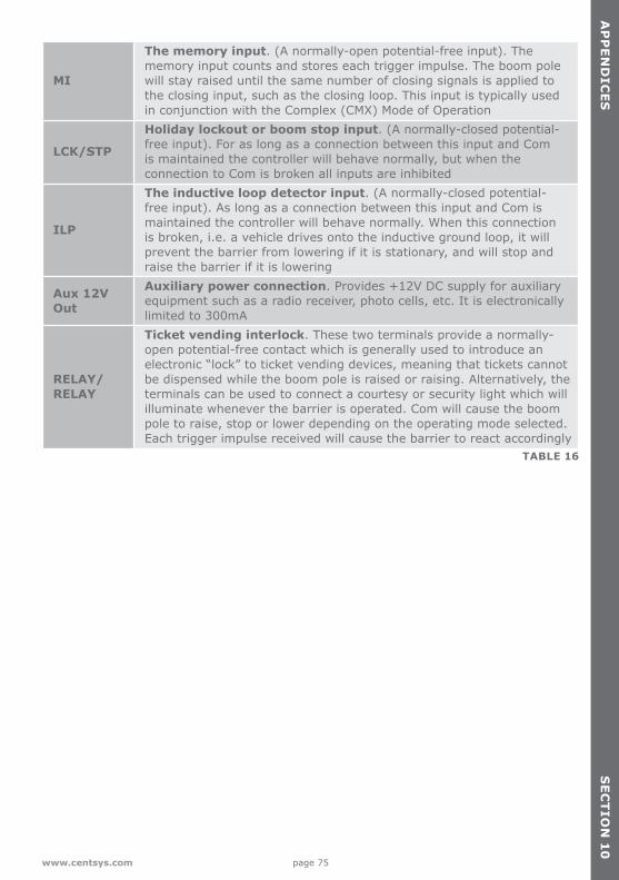
page 75www.centsys.com
MI
The memory input. (A normally-open potential-free input). The memory input counts and stores each trigger impulse. The boom pole will stay raised until the same number of closing signals is applied to the closing input, such as the closing loop. This input is typically used in conjunction with the Complex (CMX) Mode of Operation
LCK/STP
Holiday lockout or boom stop input. (A normally-closed potential-free input). For as long as a connection between this input and Com is maintained the controller will behave normally, but when the connection to Com is broken all inputs are inhibited
ILP
The inductive loop detector input. (A normally-closed potential-free input). As long as a connection between this input and Com is maintained the controller will behave normally. When this connection is broken, i.e. a vehicle drives onto the inductive ground loop, it will prevent the barrier from lowering if it is stationary, and will stop and raise the barrier if it is lowering
Aux 12V Out
Auxiliary power connection. Provides +12V DC supply for auxiliary equipment such as a radio receiver, photo cells, etc. It is electronically limited to 300mA
RELAY/ RELAY
Ticket vending interlock. These two terminals provide a normally-open potential-free contact which is generally used to introduce an electronic “lock” to ticket vending devices, meaning that tickets cannot be dispensed while the boom pole is raised or raising. Alternatively, the terminals can be used to connect a courtesy or security light which will illuminate whenever the barrier is operated. Com will cause the boom pole to raise, stop or lower depending on the operating mode selected. Each trigger impulse received will cause the barrier to react accordingly
TABLE 16
AP
PE
ND
ICE
SS
EC
TIO
N 1
0
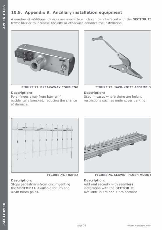
page 76 www.centsys.com
10.9. Appendix 9. Ancillary installation equipmentA number of additional devices are available which can be interfaced with the SECTOR II traffic barrier to increase security or otherwise enhance the installation.
SE
CT
ION
10
AP
PE
ND
ICE
S
FIGURE 72. BREAKAWAY COUPLING
FIGURE 74. TRAPEX
FIGURE 73. JACK-KNIFE ASSEMBLY
FIGURE 75. CLAWS - FLUSH MOUNT
Description:Pole hinges away from barrier if accidentally knocked, reducing the chance of damage.
Description: Stops pedestrians from circumventing the SECTOR II. Available for 3m and 4.5m boom poles.
Description: Used in cases where there are height restrictions such as undercover parking
Description: Add real security with seamless integration with the SECTOR IIAvailable in 1m and 1.5m sections.
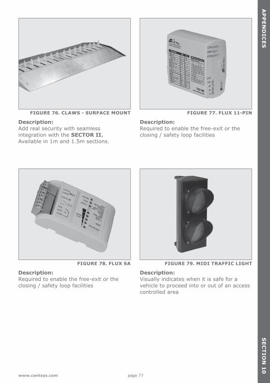
page 77www.centsys.com
AP
PE
ND
ICE
SS
EC
TIO
N 1
0
FIGURE 76. CLAWS - SURFACE MOUNT
FIGURE 78. FLUX SA FIGURE 79. MIDI TRAFFIC LIGHT
FIGURE 77. FLUX 11-PIN
Description: Add real security with seamless integration with the SECTOR II.Available in 1m and 1.5m sections.
Description:Required to enable the free-exit or the closing / safety loop facilities
Description:Visually indicates when it is safe for a vehicle to proceed into or out of an access controlled area
Description: Required to enable the free-exit or the closing / safety loop facilities
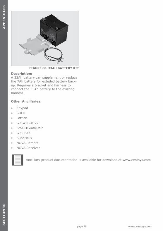
page 78 www.centsys.com
SE
CT
ION
10
AP
PE
ND
ICE
S
FIGURE 80. 33AH BATTERY KIT
Description:A 33Ah battery can supplement or replace the 7Ah battery for exteded battery back-up. Requires a bracket and harness to connect the 33Ah battery to the existing harness.
Other Ancillaries:
• Keypad• SOLO• Lattice• G-SWITCH-22• SMARTGUARDair• G-SPEAK• SupaHelix• NOVA Remote• NOVA Receiver
Anciillary product documentation is available for download at www.centsys.com

page 79www.centsys.com
Notes
NO
TE
S

Connect with us on:
facebook.com/centurionsystems
YouTube.com/centurionsystems
@askcenturion
Subscribe to the newsletter: www.centsys.com/subscribe
www.centsys.com
Doc number: 1246.D.01.0001_1SAP code: DOC1246D01
Call Centurion Systems (Pty) Ltd . South AfricaHead Office: +27 11 699 2400
Call Technical Support: +27 11 699 2481Monday to Friday: from 07h00 to 18h00 (GMT+2)
Saturday: from 08h00 to 16h30 (GMT+2)
E&OE Centurion Systems (Pty) Ltd reserves the right to change any product without prior notice
All product and brand names in this document that are accompanied by the ® symbol are registered trademarks in South Africa and/or other countries, in favour of Centurion Systems (Pty) Ltd, South Africa.
The CENTURION and CENTSYS logos, all product and brand names in this document that are accompanied by the TM symbol are trademarks of Centurion Systems (Pty) Ltd, in South Africa and other territories; all rights are reserved.
We invite you to contact us for further details.