Embed Size (px)
Citation preview
U.S. Department of Energy
Office of Electricity Delivery and Energy Reliability
Enhancing control systems security in the energy sector
NSTB National SCADA Test Bed
U.S. Department of Energy
Office of Electricity Delivery and Energy Reliability
Enhancing control systems security in the energy sector
NSTB National SCADA Test Bed
INL/EXT-09-15500
Study of Security Attributes of Smart Grid Systems – Current Cyber Security Issues
April 2009

INL/EXT-09-15500
Study of Security Attributes of Smart Grid Systems – Current Cyber Security Issues
April 2009
INL Critical Infrastructure Protection/Resilience Center Idaho Falls, Idaho 83415
Prepared for the Office of Electricity Delivery and Energy Reliability
Under DOE Idaho Operations Office Contract DE-AC07-05ID14517

DISCLAIMER
This information was prepared as an account of work sponsored by an agency of the U.S. Government. Neither the U.S. Government nor any agency thereof, nor any of their employees, makes any warranty, expressed or implied, or assumes any legal liability or responsibility for the accuracy, completeness, or usefulness, of any information, apparatus, product, or process disclosed, or represents that its use would not infringe privately owned rights. References herein to any specific commercial product, process, or service by trade name, trade mark, manufacturer, or otherwise, does not necessarily constitute or imply its endorsement, recommendation, or favoring by the U.S. Government or any agency thereof. The views and opinions of authors expressed herein do not necessarily state or reflect those of the U.S. Government or any agency thereof.

iii
ABSTRACT
This document provides information for a report to congress on Smart Grid security as required by Section 1309 of Title XIII of the Energy Independence and Security Act of 2007. The security of any future Smart Grid is dependent on successfully addressing the cyber security issues associated with the nation’s current power grid. Smart Grid will utilize numerous legacy systems and technologies that are currently installed. Therefore, known vulnerabilities in these legacy systems must be remediated and associated risks mitigated in order to increase the security and success of the Smart Grid. The implementation of Smart Grid will include the deployment of many new technologies and multiple communication infrastructures. This report describes the main technologies that support Smart Grid and summarizes the status of implementation into the existing U.S. electrical infrastructure.

iv

v
EXECUTIVE SUMMARY
This document provides information in support of a report to congress required by the Energy Independence and Security Act of 2007. This document focuses on the cyber security issues associated with the nation’s power grid as it exists today.
The operation and control of the current power grid depends on a complex network of computers, software, and communication technologies that, if compromised by an intelligent adversary, have the potential to cause great damage, including extended power outages and destruction of electrical equipment. A cyber attack has the unique attribute that it can be launched through the public network from a remote location anywhere in the world and coordinated to attack many locations simultaneously. Efforts by the energy sector to uncover system vulnerabilities and develop effective countermeasures so far have prevented serious damage. However, attacks on energy control systems have been successful.
The legacy communication methods that now support grid operations also provide potential cyber attack paths. Many cyber vulnerabilities have been identified by cyber security assessments of Supervisory Control and Data Acquisition (SCADA) systems. Power grid substation automation and security have also recently been evaluated. The level of automation in substations is increasing, which can lead to more cyber security issues. The cyber security issues identified during the assessments and evaluations need to be resolved, but the known issues should not be construed as a complete assessment of the current power grid security posture. Some of these vulnerabilities are in the process of being mitigated, and some known vulnerabilities have not been made public.
The implementation of the Smart Grid will include the deployment of many new technologies including advanced sensors to improve situational awareness, advanced metering, automatic meter reading, and integration of distributed generation resources such as photovoltaic arrays and wind turbines. These new technologies will require the addition of multiple communication mechanisms and communication infrastructures that must be coordinated with numerous legacy systems and technologies that are currently installed. These technologies are now in the process of deployment and recent studies have shown that the deployed Smart Grid components have significant cyber vulnerabilities. Therefore, known vulnerabilities in these systems must be remediated and associated risks mitigated in order to increase the security and success of the Smart Grid.
The complexity of the grid implies that vulnerabilities exist that have not yet been identified. It is particularly difficult to estimate risk from cyber attack because of the size, complexity, and dynamic nature of the power grid and the unpredictability of potential attackers. Nevertheless, in light of known vulnerabilities and the potential for extreme damage from a cyber attack, there is a clear need for cyber security improvements in the current power grid. There must be a coordinated and ongoing effort to secure the Smart Grid that includes the full development lifecycle. The development life cycle includes requirements, design, implementation, verification, validation, procurement, installation, operations, and maintenance. There should be incentives put in place that encourage vendors and power companies to place sufficient emphasis on the security aspects of the Smart Grid lifecycle.

vi
vii
CONTENTS
ABSTRACT........................................................................................................................................... iii
ACRONYMS......................................................................................................................................... ix
1. INTRODUCTION......................................................................................................................... 1
2. CYBER VULNERABILITIES IN THE LEGACY POWER GRID................................................ 2
2.1 SCADA Security................................................................................................................. 2
2.2 Substation Security.............................................................................................................. 2
2.3 Legacy Communication Networks ....................................................................................... 2
2.4 Legacy Grid Current Risk.................................................................................................... 3
3. SMART GRID TECHNOLOGIES ................................................................................................ 4
3.1 Smart Grid Network ............................................................................................................ 4
3.2 Advanced Metering ............................................................................................................. 4
3.3 Phasor Measurement Units .................................................................................................. 6
3.4 Renewable, Distributed Power Generation........................................................................... 7
3.5 Energy Storage.................................................................................................................... 7
4. SMART GRID DEPLOYMENT STATUS.................................................................................... 9
5. SECURITY OF CURRENT SMART GRID TECHNOLOGY..................................................... 12
5.1 AMI Security .................................................................................................................... 12
5.2 Wireless Network Security ................................................................................................ 12
5.3 NASPI Security................................................................................................................. 13
5.4 Potential Attack Scenarios ................................................................................................. 13
5.5 Current Risk of Attack through Smart Grid Technology..................................................... 13
6. CONCLUSIONS AND RECOMMENDATIONS........................................................................ 14
7. REFERENCES............................................................................................................................ 15
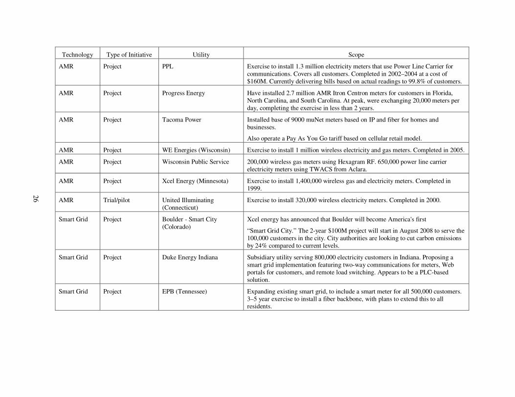
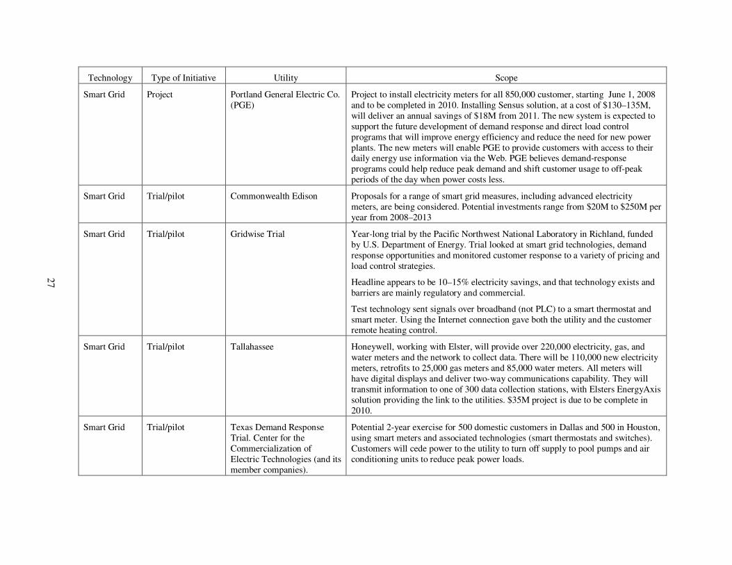
Appendix A—Smart Metering Initiatives in the United States................................................................ 17
FIGURES
Figure 1. Block diagram of typical smart grid components and connections. ............................................ 5
Figure 2. Map of smart metering initiatives in the United States as of March 2009. .................................. 9
TABLES
Table 1. Summary of electrical smart metering initiatives within the United States. ............................... 10

viii
ix
ACRONYMS
AMI Advanced Metering Infrastructure
AMI-SEC AMI Security
AMR Automated Meter Reading
ATM Asynchronous Transfer Mode
C&I Commercial & Industrial
CAES Compressed Air Energy Storage
CPP Critical Peak Pricing
CPUC California Public Utilities Commission
DMZ Demilitarized Zone
DNP3 Distributed Network Protocol
DOE Department of Energy
FTP File Transfer Protocol
HAN Home Area Network
HECO Hawaiian Electric Company
HTTP Hypertext Transfer Protocol
ICCP Inter-Control Center Communications Protocol
INL Idaho National Laboratory
IP Internet Protocol
ISO Independent System Operator
MDM Meter data management
MitM Man-in-the-Middle
NASPI North American SynchroPhasor Initiative
NASPInet NASPI Network
NERC North American Electric Reliability Corporation
NSTB National SCADA Test Bed
NVD National Vulnerability Database
OASIS Open Access Same-Time Information System
PGE Portland General Electric Company
PHEV Plug-in Hybrid Electric Vehicle
PLC Programmable Logic Controller
PMU Phasor Measurement Unit
PNNL Pacific Northwest National Laboratory
PSTN Public Switched Telephone Network

x
PV Photovoltaic
RF Radio Frequency
RTO Regional Transmission Organization
SCADA Supervisory Control and Data Acquisition
SCE Southern California Edison
SMES Superconducting Magnetic Energy Storage
SOA Service Oriented Architecture
SSVEC Sulphur Springs Valley Electric
TCP Transmission Control Protocol
ToU Time of Use
TWACS Two-Way Automatic Communications System
VAR Volts Amps Reactive
WiFi Wireless Fidelity
1
Study of Security Attributes of Smart Grid Systems – Current Cyber Security Issues
1. INTRODUCTION
This document provides information in support of a report to congress required by the Energy Independence and Security Act of 2007. Section 1309 of Title XIII of the Energy Independence and Security Act of 2007 requires a report to congress that includes specific recommendations on each of the following:
1. How Smart Grid systems can help in making the nation’s electricity system less vulnerable to disruptions due to intentional acts against the system.
2. How Smart Grid systems can help in restoring the integrity of the nation’s electricity system subsequent to disruptions.
3. How Smart Grid systems can facilitate nationwide, interoperable emergency communications and control of the nation’s electricity system during times of localized, regional, or nationwide emergency.
4. What risks must be taken into account that Smart Grid systems may, if not carefully created and managed, create vulnerability to security threats of any sort, and how such risks may be mitigated.
Pacific Northwest National Laboratory (PNNL) is preparing a more complete report that fully addresses each of the above questions for the Department of Energy (DOE). This document provides input to that PNNL report and focuses primarily on the cyber security risks associated with the nation’s power grid as it exists today.
The operation and control of the current power grid depends on a complex network of computers, software, and communication technologies that, if compromised by an intelligent adversary, could be used to cause great damage, including extended power outages and destruction of electrical equipment. Any prolonged or widespread disruption of energy supplies could produce devastating human and economic consequences. A cyber attack has the unique attribute that it may be launched through the public network from a remote location anywhere in the world and could be coordinated to attack many locations simultaneously. Efforts by the energy sector to uncover system vulnerabilities and develop effective countermeasures have so far prevented serious damage. However, attacks on energy control systems have been successful.
The implementation of the Smart Grid includes the deployment of many new technologies and multiple communication infrastructures. Smart grid technologies have already been deployed in some locations. These technologies have many known cyber security vulnerabilities that need to be addressed. These Smart Grid technologies now being deployed will be implemented by incremental changes to the existing national electricity infrastructure; therefore, the cyber vulnerabilities in the legacy infrastructure should be recognized and addressed as part of the Smart Grid implementation.
2
2. CYBER VULNERABILITIES IN THE LEGACY POWER GRID
The legacy power grid is managed through control centers, electronic monitoring/control equipment at substations, and an extensive communication network.
2.1 SCADA Security
Supervisory Control and Data Acquisition (SCADA) systems are used extensively to control and monitor the national power grid. SCADA systems have undergone cyber security assessments as part of the National SCADA Test Bed (NSTB) program. Idaho National Laboratory (INL) has extensive experience in conducting SCADA security assessments and has performed over 58 assessments over several years, on a variety of control system products, and in laboratory settings as well as in onsite operational environments including electric power grid facilities. Many vulnerabilities were found during these assessments. The identified vulnerabilities were categorized and described in a 2008 INL report.1 A vulnerability is included in this report only if it was observed in at least two independent assessments. All these results are applicable to products and installations that are part of the current power grid. Many vulnerabilities exist in SCADA systems that have not been publically disclosed. For example, the National Vulnerability Database (NVD) receives, on average, 15 new publically disclosed vulnerabilities each day. It is estimated2 that at least 12% of all reported vulnerabilities apply to control systems; therefore, many vulnerabilities exist that have not yet been made public, but could be exploited by a knowledgeable attacker.
2.2 Substation Security
A recent study3 of North American power grid substations was conducted jointly by INL and Newton-Evans Research Company to evaluate the substation level of automation and security posture. Substations contain transmission and distribution devices such as circuit breakers, power transformers, phase-shifting transformers, capacitor banks, and disconnect switches. Substations may also contain various electronic automation and communication devices used to measure, monitor, and control the substation components. There are approximately 17,325 transmission substations in the U.S. and Canada. Overall, 81% of transmission substations have some level of automation, while only 57% of distribution-type substations have some level of automation. The level of automation in substations is increasing. Level of automation is indirectly related to security because increased automation implies increased computer-controlled electronics and software, which tends to increase the potential for cyber security weaknesses. Increased automation does not necessarily imply reduced security; however, the study identified many vulnerabilities associated with substation automation devices and described the potential consequences of exploitation of substation vulnerabilities. Potential consequences of successful substation cyber attacks include the destruction of generators, power outages, and grid instability.
2.3 Legacy Communication Networks
Various communication technologies are used in the power grid to support operations. Control centers within utilities, regional transmission operator/independent system operators (RTO/ISOs) are in constant communication with each other and with substations in order to maintain balance between power generation and demand, maintain voltages and frequencies, respond to changing conditions, provide real-time power market access, etc. The communication media used to transfer data between grid entities include frame relay networks, asynchronous transfer mode (ATM), public switched telephone network (PSTN), the Internet, and wireless technologies such as wireless modems, microwave, and satellites. There are also many data exchange protocols used between entities within the power grid. Some of these protocols such as Transmission Control Protocol (TCP)/Internet Protocol (IP), Hypertext Transfer Protocol (HTTP), and File Transfer Protocol (FTP) are also widely used in the global Information Technology domain. Some protocols, such as Distributed Network Protocol (DNP) 3.0, were designed for
3
control system communications. Inter-control Center Communications Protocol (ICCP) was designed and used for communications between power grid control centers. The Open Access Same-Time Information System (OASIS) uses the Internet to provide fair market access to the transmission grid. All these communication methods provide potential attack paths for cyber attackers. There are many known vulnerabilities associated with these communication media and communication protocols. The power grid is increasingly connected to the Internet, which has inherent security weaknesses.
2.4 Legacy Grid Current Risk
The cyber vulnerabilities that have been identified during the assessments and evaluations are indicative of some of the issues that need to be addressed or are being addressed, but these known issues should not be construed as a complete assessment of the current power grid security posture. Some of these vulnerabilities are in the process of being mitigated. The communication mechanisms and control systems associated with the power grid are continually in the process of incremental change. The size and dynamic nature of the power grid makes it particularly difficult to estimate risk from cyber attack. Cyber security risk is difficult to measure even in a static environment because it is a complex function of threat, vulnerabilities and consequences. The threat is an unpredictable intelligent adversary, the vulnerabilities are dynamic and difficult to identify, and the consequences of a successful cyber attack are difficult to predict. Nevertheless, in light of known vulnerabilities and the potential for extreme damage from a cyber attack, there is a clear need for cyber security improvements in the legacy power grid on which the Smart Grid will be built.
4
3. SMART GRID TECHNOLOGIES
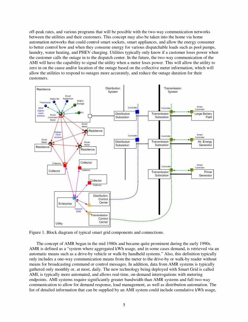
The vision of the Smart Grid is a modern, improved, resilient, and reliable electric grid that provides for environmental stewardship, is secure, cost effective, and is a predominant driver to economic stability and/or development. Figure 1 is a block diagram that shows typical components of smart grid and the communication paths that will connect the components.
The electric power industry relies heavily on control systems to manage and control the generation, transmission, and distribution of electric power. Many of the control systems in service today were designed for operability and reliability during a time when security was a low priority. Smart Grid implementation is going to require the installation of numerous advanced control system technologies along with greatly enhanced communication networks. The following paragraphs describe some of the more significant elements of the Smart Grid.
3.1 Smart Grid Network
One key element of the new Smart Grid is the installation of a completely new two-way communication network between the energy suppliers and their customers. This communication network will be constructed to enable new energy concepts such as real-time pricing, load shedding, consumption management, cost savings from peak load reduction, cost savings from energy efficiency, integration of plug-in hybrid electric vehicles for grid energy storage, and the integration of distributed generation such as photovoltaic systems and wind turbines. This new network will be constructed using various communication paths including fiber optic cable, hybrid fiber coax, twisted pair, broadband over power line, and wireless technology. These types of communication networks are all currently operating in the nation’s electric grid, but are not yet implemented to the extent that will be required for enabling the Smart Grid.
Figure 1 shows network connections that can be traced from the customer’s premises to collector nodes, then to the utility control center and to transmission and distribution substations where the electronic controllers are located that control the generation and flow of electrical power. The residence block in Figure 1 represents the Home Area Network (HAN) that may include communicating Smart Grid components such as a Smart Thermostat, Smart Water Heater, Smart Appliances, plug-in hybrid electric vehicle (PHEV)/storage, and Photovoltaics (PV). Notice, the HAN communication devices may control power sources as well as power consuming equipment. All the HAN devices are connected to a Smart Controller/Meter through a network such as Zigbee or mesh wireless. The Smart Controller/Meter connects the HAN to a collector node also through a network such as Zigbee or mesh wireless (and incidentally may also communicate with the HAN networks located near by). Collector nodes communicate with the utility through common communication mechanisms including the Internet. Intranet communication paths within the utility premises include a Demilitarized Zone (DMZ) that is designed to impede the flow of unauthorized messages. The Distribution and Transmission control centers have legacy communication paths and additional Smart Grid communication paths.
3.2 Advanced Metering
Several utilities in the United States are currently replacing their revenue meters with new smart meters that allow full two-way communication. The deployment of advanced metering infrastructure (AMI) and automated meter reading (AMR) capabilities in the power distribution system has the potential to save energy suppliers and their consumer’s significant amounts of money in the near term. The energy suppliers can benefit by more efficient meter reading, fewer truck rolls (i.e., fewer maintenance personnel dispatch events), outage location identification, remote connect/disconnect, etc. Energy consumers will also have new opportunities to reduce their energy costs by taking advantage of real-time energy pricing,
5
off-peak rates, and various programs that will be possible with the two-way communication networks between the utilities and their customers. This concept may also be taken into the home via home automation networks that could control smart sockets, smart appliances, and allow the energy consumer to better control how and when they consume energy for various dispatchable loads such as pool pumps, laundry, water heating, and PHEV charging. Utilities typically only know if a customer loses power when the customer calls the outage in to the dispatch center. In the future, the two-way communication of the AMI will have the capability to signal the utility when a meter loses power. This will allow the utility to zero in on the cause and/or location of the outage based on the collective meter information, which will allow the utilities to respond to outages more accurately, and reduce the outage duration for their customers.
Figure 1. Block diagram of typical smart grid components and connections.
The concept of AMR began in the mid 1980s and became quite prominent during the early 1990s. AMR is defined as a “system where aggregated kWh usage, and in some cases demand, is retrieved via an automatic means such as a drive-by vehicle or walk-by handheld systems.” Also, this definition typically only includes a one-way communication means from the meter to the drive-by or walk-by reader without means for broadcasting command or control messages. In addition, data from AMR systems is typically gathered only monthly or, at most, daily. The new technology being deployed with Smart Grid is called AMI, is typically more automated, and allows real-time, on-demand interrogations with metering endpoints. AMI systems require significantly greater bandwidth than AMR systems and full two-way communication to allow for demand response, load management, as well as distribution automation. The list of detailed information that can be supplied by an AMI system could include cumulative kWh usage,
6
daily kWh usage, peak kW demand, last interval demand, load profile, voltage, voltage profile, logs of voltage sag and swell events, voltage event flags, phase information, outage counts, outage logs, tamper notification, power factor, and time-of-use kWh and peak kW readings. With high-end AMI systems nearly all of this information is available in real time and on demand, allowing for improved operations and customer management. AMI systems can also be used to verify power outages and service restoration, perform remote-service disconnects and reconnects, allow automated net metering, transmit demand-response and load-management messages, interrogate and control distribution-automation equipment, and facilitate prepaid metering.
3.3 Phasor Measurement Units
The concept of the Smart Grid begins with the fundamental need to increase the reliability and efficiency of the nation’s transmission systems and centralized generating assets. The integration of phasor measurement units and other advanced sensors into comprehensive wide-area monitoring networks will enhance the situational awareness of the national grid and enable system operators to react to system disturbances and anomalies more accurately and expeditiously. The data collected by these systems can be used to develop advanced operating procedures/algorithms and ultimately allow some level of automatic advanced control of the grid. The data from these systems could also be utilized to make the national grid self healing by avoiding or mitigating power outages, power quality problems, and service disruptions.
The North American SynchroPhasor Initiative (NASPI) has been established and is currently funded by the North American Electric Reliability Corporation (NERC). The following provides a brief summary of the use of Syncrophasor measurements, additional information is available at www.naspi.org. Synchrophasors are precise measurements of voltages, currents, and frequency at high speeds. Each measurement is time-stamped using the universal time standard, which allows all synchrophasor measurements to be synchronized and time-aligned, regardless of where in the system the measurement is taken. This allows all measurements from around the country to be combined to create an accurate picture of very large interconnected systems. These signals are fed into processing applications that allow grid operators to view and understand the state of the grid with very high fidelity and to see early evidence of changing conditions and emerging grid problems. These new measurements are used to perform detailed power system planning and forensic analysis, and will be a key component of the Smart Grid. Currently, there are around 200 phasor measurement units (PMUs) installed in the continental United States with many more to be installed in the near future. NASPI has developed a deployment roadmap for PMU installation and specified standard voltage levels where they should be installed. By 2014, NASPI states that “phasor data will be fully trusted as accurate and useful, and will be routinely used for the following purposes”:
• Post mortem forensic analysis of all grid disturbances
• Monitoring and visualization of angle differences, voltage stability, frequency, and thermal overloads
• Power plant monitoring and integration, including intermittent resources and distributed generation
• Power system restoration
• Static model benchmarking
• State estimation
• Automated control of local assets.
They further state that by 2019, phasor data will be used for:
• Dynamic state estimation

7
• Alarming for situational awareness tools
• Day and hour-ahead operations planning
• Planned power system separation
• Real-time automated grid controls and adaptive protection on a wide-area basis
• Congestion management
• Inter-area oscillation damping modulation controls
• System integrity protection schemes
• Dynamic model benchmarking
• Dynamic line ratings and Volts Amps Reactive (VAR) support
• Unit dispatch
• Automatically manage frequency and voltage response from load
• Distribution network monitoring, restoration and self-healing.
3.4 Renewable, Distributed Power Generation
Another key aspect of the smart grid is to accommodate the integration of new distributed generation resources such as wind turbines, photovoltaic arrays, micro turbines, and combined heat and power generators in buildings. Historically, the integration of distributed generation by independent power producers to a large utility grid has been a very small percentage of the utilities capacity. However, the recent thrust in large-scale deployment of distributed resources will necessitate substantial enhancements in the communication and control mechanisms required by utilities to integrate these new generation sources into their grid without creating stability and load balancing problems. This is particularly important with the deployment of non-dispatchable resources, such as photovoltaic arrays and wind turbines, since other sources of generation will need to anticipate the variations in output from these types of generators and be available to respond quickly.
3.5 Energy Storage
Without the capability to store electrical energy, an instantaneous balance between energy production and demand needs to be maintained on the grid. In the past, grid energy storage systems were typically not economically feasible; however, PHEVs may provide part of the solution to this problem. The integration of smart charging systems and active control systems for PHEVs could allow participants to choose to let their energy supplier dispatch the stored energy in the vehicles batteries during specific periods of peak load. This could flatten the peak demand curve and ultimately reduce the cost of energy for consumers as well as enhance the integration of non-dispatchable generation resources into the electric grid. Many other concepts for grid energy storage have been developed such as pumped storage hydroelectric, batteries, compressed air energy storage, thermal energy storage, flywheel energy storage, and superconducting magnetic energy storage to name a few. A recent report by the Electricity Advisory Committee4 details the current technologies for grid energy storage and discusses their applicability for the grid of tomorrow. The following text provides a brief summary of these technologies.
The most prevalent large-scale energy storage installations today are pumped storage hydroelectric. Currently there is approximately 90GW of pumped storage in service around the world and approximately 22GW of this is in the U.S. These installations require a water source as well as two separate reservoirs at different elevations to generate the net head necessary to generate power. Pumped storage hydroelectric is

8
very responsive and can be ramped up or down very quickly as conditions warrant. Historically, pumped storage hydroelectric has been the most cost effective form of mass power energy storage; however, these projects are difficult to permit and construct, and large-scale deployment of additional pumped storage hydroelectric facilities is not likely.
The traditional lead acid batteries used in automobiles are too costly, have high maintenance needs, and do not have the lifespan to meet the needs of large-scale grid energy storage. Newer technologies such as zinc-bromine, sodium-sulfur, and the more familiar lithium-ion batteries offer enhanced performance and durability. Zinc-bromine and sodium-sulfur batteries are classified as “flow batteries.” A flow battery is a rechargeable battery in which an electroactive fluid flows through a reactor that converts chemical energy to electricity and consists of electrochemical cell stacks, electrolyte storage reservoirs, and an electrolyte circulation system. They are unique in that they can be recharged very quickly by changing the electrolyte similar to refilling a fuel tank. Therefore, the output capacity of the flow battery is only limited to the amount of electrolyte storage available at the facility. The spent electrolyte is recovered and re-energized at a time when the battery output is not needed such as a period of off-peak energy demand. Some types of flow batteries are considered proven technology; however, their cost is considered too expensive for large-scale deployment. Additional research is being conducted with flow battery technology and may prove to be a valuable source of future grid energy storage.
Superconducting magnetic energy storage systems (SMES) store energy in the magnetic field created by the flow of direct current in a superconducting coil, which is cryogenically cooled to a temperature that is below its superconducting critical temperature. Once the superconducting coil is charged, the current will not decay and the magnetic energy can be stored indefinitely. When desired, the stored magnetic energy can be released by discharging the coil. This technology requires substantial energy for the refrigeration, and therefore is typically used to store energy for short durations.
Flywheel energy storage is another technology that is used to provide short duration energy storage. An electric motor accelerates the mechanical inertia of a heavy rotating disc, which acts as a generator upon reversal, slowing down the disk and producing electricity. The range of power and energy technically and economically achievable; however, it tends to make flywheel energy storage suitable for load leveling applications as opposed to general power systems applications.
Compressed air energy storage (CAES) is another technology being developed to provide large-scale grid energy storage. Compressed air is pumped into underground formations such as salt domes, or depleted gas fields during periods of minimum demand. This compressed air is then released from storage, mixed with fuel, and burned in a turbine to drive a generator during periods of peak demand. This technology has been successfully demonstrated; however, significant research and development still needs to be conducted in order for this to become a major resource in the future grid energy storage market.
The integration of distributed generation, including wind turbines, photovoltaic, and micro turbines into the grid, will require a substantial backup source generation or some form of energy storage system to ensure initial energy balance. Energy storage systems will increase the capability of micro grids to operate as stand-alone islands. This has the potential to dramatically reduce the cascading effects of major system disturbances such as the August 2003 northeast blackout.
9
4. SMART GRID DEPLOYMENT STATUS
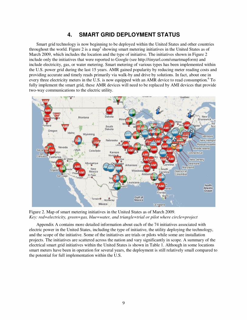
Smart grid technology is now beginning to be deployed within the United States and other countries throughout the world. Figure 2 is a map5 showing smart metering initiatives in the United States as of March 2009, which includes the location and the type of initiative. The initiatives shown in Figure 2 include only the initiatives that were reported to Google (see http://tinyurl.com/smartmapform) and include electricity, gas, or water metering. Smart metering of various types has been implemented within the U.S. power grid during the last 15 years. AMR gained popularity by reducing meter reading costs and providing accurate and timely reads primarily via walk-by and drive by solutions. In fact, about one in every three electricity meters in the U.S. is now equipped with an AMR device to read consumption.6 To fully implement the smart grid, these AMR devices will need to be replaced by AMI devices that provide two-way communications to the electric utility.
Figure 2. Map of smart metering initiatives in the United States as of March 2009. Key: red=electricity, green=gas, blue=water, and triangle=trial or pilot where circle=project
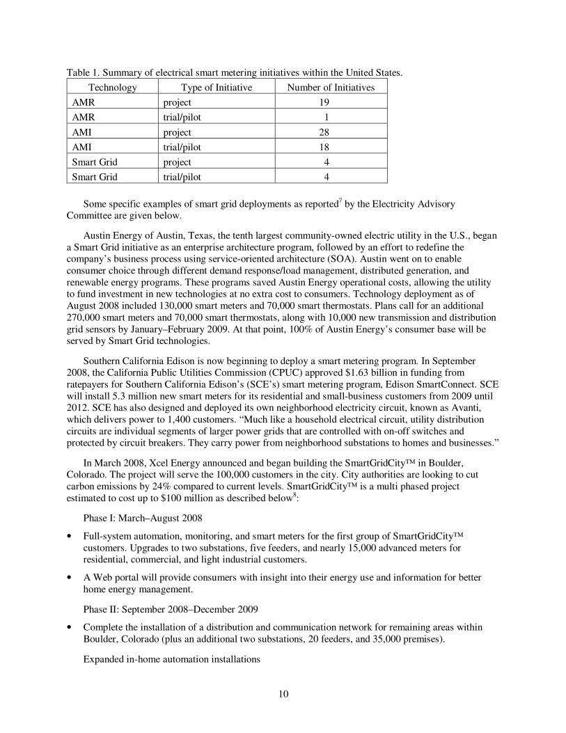
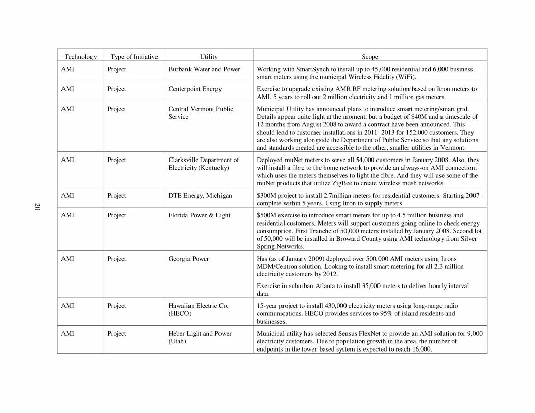
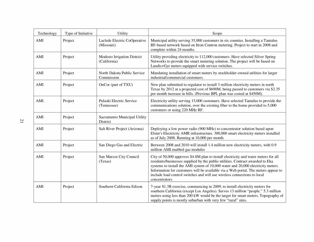
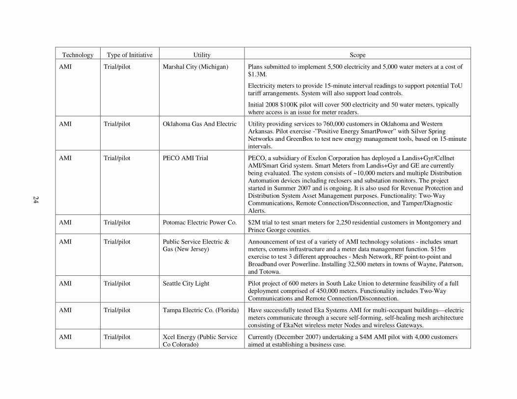
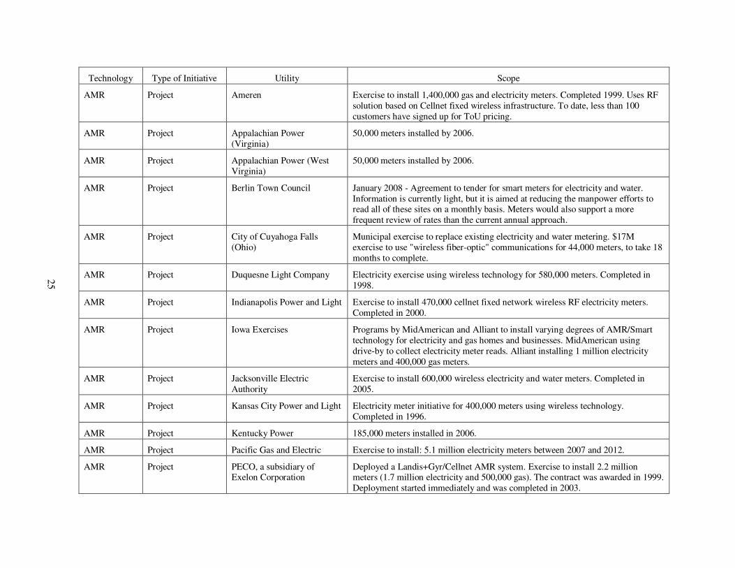
Appendix A contains more detailed information about each of the 74 initiatives associated with electric power in the United States, including the type of initiative, the utility deploying the technology, and the scope of the initiative. Some of the initiatives are trials or pilots while some are installation projects. The initiatives are scattered across the nation and vary significantly in scope. A summary of the electrical smart grid initiatives within the United States is shown in Table 1. Although in some locations smart meters have been in operation for several years, the deployment is still relatively small compared to the potential for full implementation within the U.S.
10
Table 1. Summary of electrical smart metering initiatives within the United States.
Technology Type of Initiative Number of Initiatives
AMR project 19
AMR trial/pilot 1
AMI project 28
AMI trial/pilot 18
Smart Grid project 4
Smart Grid trial/pilot 4
Some specific examples of smart grid deployments as reported7 by the Electricity Advisory Committee are given below.
Austin Energy of Austin, Texas, the tenth largest community-owned electric utility in the U.S., began a Smart Grid initiative as an enterprise architecture program, followed by an effort to redefine the company’s business process using service-oriented architecture (SOA). Austin went on to enable consumer choice through different demand response/load management, distributed generation, and renewable energy programs. These programs saved Austin Energy operational costs, allowing the utility to fund investment in new technologies at no extra cost to consumers. Technology deployment as of August 2008 included 130,000 smart meters and 70,000 smart thermostats. Plans call for an additional 270,000 smart meters and 70,000 smart thermostats, along with 10,000 new transmission and distribution grid sensors by January–February 2009. At that point, 100% of Austin Energy’s consumer base will be served by Smart Grid technologies.
Southern California Edison is now beginning to deploy a smart metering program. In September 2008, the California Public Utilities Commission (CPUC) approved $1.63 billion in funding from ratepayers for Southern California Edison’s (SCE’s) smart metering program, Edison SmartConnect. SCE will install 5.3 million new smart meters for its residential and small-business customers from 2009 until 2012. SCE has also designed and deployed its own neighborhood electricity circuit, known as Avanti, which delivers power to 1,400 customers. “Much like a household electrical circuit, utility distribution circuits are individual segments of larger power grids that are controlled with on-off switches and protected by circuit breakers. They carry power from neighborhood substations to homes and businesses.”
In March 2008, Xcel Energy announced and began building the SmartGridCity™ in Boulder, Colorado. The project will serve the 100,000 customers in the city. City authorities are looking to cut carbon emissions by 24% compared to current levels. SmartGridCity™ is a multi phased project estimated to cost up to $100 million as described below8:
Phase I: March–August 2008
• Full-system automation, monitoring, and smart meters for the first group of SmartGridCity™ customers. Upgrades to two substations, five feeders, and nearly 15,000 advanced meters for residential, commercial, and light industrial customers.
• A Web portal will provide consumers with insight into their energy use and information for better home energy management.
Phase II: September 2008–December 2009
• Complete the installation of a distribution and communication network for remaining areas within Boulder, Colorado (plus an additional two substations, 20 feeders, and 35,000 premises).
Expanded in-home automation installations

11
• Enable Web portal access to all SmartGridCity™ customers
• Deploy additional smart meters
• Commence integration of PHEVs, solar, and wind co-generation sources onto Boulder’s grid.
This project is one of the first of its kind. Historically the installation of communication networks and automation devices on the power system has been focused on the generation, transmission, and distribution systems owned and operated by the utilities. Xcel Energy states in their plan for Boulder that they intend to use the SmartGridCity™ project as a test bed to prove the success of the available technologies and then scale the applications to other portions of their eight state service territory as prudent.
12
5. SECURITY OF CURRENT SMART GRID TECHNOLOGY
Although the vision of Smart Grid includes enhanced security, the introduction of supporting technologies such as smart meters, sensors, and advanced networks can introduce new vulnerabilities. In fact, Smart Grid technologies have known cyber security vulnerabilities.
5.1 AMI Security
AMI is one of the key technologies required to enable several of the Smart Grid characteristics, and it plays some role in all of them. For this reason, AMI must be viewed as a foundational-enabling technology for the Smart Grid. The Open Smart Grid Users Group (http://osgug.ucaiug.org) formed an AMI security (AMI-SEC) task force in August of 2007 to address AMI security issues. AMI-SEC recently released a Security Specification9 and a Security Implementation Guide10 for AMI. These documents provide useful guidance; however, the current implementations of AMI are known to have significant security issues.
A recent study11 by Goodspeed et al. identified several methods for attacking wireless devices used in AMI networks. The wireless devices are used in the smart meters located on the customers’ premises. Since these devices are outside the utility’s physical security perimeter, they are at high risk of compromise. Goodspeed documented how attackers can extract data from the memory of these devices including keys used for network authentication and how the device memory can be modified by an attacker to insert malicious software. Once the device is compromised it can be used to attack other parts of the Smart Grid by communicating through the network. Attacks that originate with an AMI wireless network device can lead to direct control systems compromise.
Carpenter12 also documented many vulnerabilities in AMI devices including insecure data buses and serial connections. Because the cost of Smart Meters is low, there is no significant barrier to entry for hackers interested in attacking AMI. AMI security, as it currently stands, is insufficient to protect the national power grid from attack by malicious and knowledgeable groups.
5.2 Wireless Network Security
Wireless networks are commonly used in the current Smart Grid deployments. Wireless networks were employed because they have some significant advantages over other alternatives. Wireless devices are plentiful and inexpensive. Some AMI implementations use mesh networks with wireless devices to provide self-adapting multi-path multi-hop communications between AMI nodes. Mesh networks are considered very reliable because they provide redundant communication paths that compensate for failures from natural causes. For example, ZigBee is a low-cost, low-power, wireless mesh networking standard. The low cost allows the technology to be widely deployed in wireless control and monitoring applications, the low power-usage allows longer life with smaller batteries, and the mesh networking provides high reliability and a larger range. However, mesh networks are vulnerable to attack by an intelligent adversary.
Because Zigbee, and other wireless communication standards such as ISA 100.11a and Wireless HART are in the early stages of development and deployment, there is not much publicly available information regarding their security. However, IEEE 802.15.4 protocol is the basis for all of these technologies and there are known vulnerabilities associated with IEEE 802.15.4 implementations. For example, Brodsky et al.13 documented a denial-of-service attack on IEEE 802.15.4 wireless networks used within the Smart Grid. The equipment needed for such an attack is inexpensive (about $70).
Vendors of wireless AMI technology claim to provide security features, but in a rush to be first to market, security may not receive sufficient emphasis. This implies a need for more security research on IEEE 802.15.4-based networks and other wireless networks intended for AMI.
13
5.3 NASPI Security
The implementation of the North American SynchroPhasor Initiative (NASPI) requires a new communications network (NASPInet) to provide real-time monitoring of the PMUs. The communication mechanisms that now support the initial introduction of NASPI were in place previously and are not necessarily intended to support the critical infrastructure. Security standards for the long-term NASPI network are not yet available.14 At this time there are only about 200 PMUs installed in the continental United States, therefore the security of the network that supports NASPI is not yet critical. NASPI network security has not yet been sufficiently explored.
5.4 Potential Attack Scenarios
Consider the potential consequences of a successful cyber attack on the Smart Grid network. Many compromised Smart Meters or data collector nodes could be programmed by the attacker to simultaneously send messages that cause power demand to be reduced dramatically and then to be increased dramatically. These phony messages could cause grid instability and power outages.
5.5 Current Risk of Attack through Smart Grid Technology
Every communication path that supports monitoring and control of the Smart Grid is a two-way communication path as shown in Figure 1. Each communication path is a potential attack path for a knowledgeable attacker. There are many potential entry points physically unprotected. Wireless networks can be easily monitored by attackers and may be susceptible to Man-in-the-Middle (MitM) attacks. There are security mechanisms in place intended to prevent unauthorized use of these communication paths, but there are weaknesses in these mechanisms. The history of security in complex networks implies that more vulnerabilities exist and are yet to be discovered.
Because Smart Grid technologies are currently deployed in a relatively small percent of the North American power grid, the national security risk posed by vulnerabilities in these new technologies may not present a significant risk at this time. However, since these devices and networks are vulnerable to attack, the risk grows as the deployment becomes more widespread.
14
6. CONCLUSIONS AND RECOMMENDATIONS
Smart Grid design and deployment must take into account the current cyber vulnerabilities in the legacy power grid. The known vulnerabilities in the existing legacy power grid should continue to be addressed and mitigated in concert with the implementation of Smart Grid technologies.
Resistance to attack is one of the seven principle characteristics of the Smart Grid vision. However, implementation of a Smart Grid that is resistant to attack is particularly difficult for several reasons. The Smart Grid deployment will increase the complexity of the existing system and will include the addition of many new communication paths. Increased complexity and expanded communication paths can easily lead to an increase in vulnerability to cyber attack. The size (millions of nodes) of a fully implemented Smart Grid and an unpredictable intelligent adversary make it difficult to anticipate how attacks may be manifested. Smart Grid technology that has known vulnerabilities has already been deployed in some parts of the current power grid. Furthermore, the goal of “resistance to attack” is in competition with some of the other desired characteristics of the Smart Grid, e.g. “optimizes assets and operates efficiently”. The desire to minimize costs and to provide services tend to take priority over the desire for security in the face of a threat that is not well understood.
There must be a coordinated and ongoing effort to secure the Smart Grid that includes the full development lifecycle. The development life cycle includes requirements, design, implementation, verification, validation, procurement, installation, operations, and maintenance. A failure in any phase of the lifecycle leads to defects, which lead to vulnerabilities that can be exploited by a skilled attacker. Incentives should established that encourage vendors and power companies to place sufficient emphasis on the security aspects of the Smart Grid lifecycle. Each of the Smart Grid components has a security life cycle that must have a disciplined development process that emphasizes security and includes independent verification and validation to ensure vulnerabilities are avoided or are found and mitigated. The components of the system must be designed for interoperability such that the emergent properties of the Smart Grid prevent successful catastrophic cyber attacks and provide for attack detection and recovery. It is imperative that the requirements, design, implementation, and operations include multi-levels of defense to prevent catastrophic consequences in case new vulnerabilities are discovered or attackers find new ways to subvert some of the defense mechanisms.
15
7. REFERENCES
1. Chaffin, May Robin, Tom, Steven M., Kuipers, David G., Boyer, Wayne, INL Report to the Department of Energy, “Common Cyber Security Vulnerabilities Observed in Control System Assessments by the INL NSTB Program,” INL/EXT-08-13979, November 2008.
2. McQueen, Miles, Wayne Boyer, Trevor McQueen, Sean McBride, “Empirical Estimates of 0Day Vulnerabilities in Control Systems,” Proceedings of the SCADA Security Scientific Symposium 2009 (S4), pp. 6-1–6-26, January 21–23, 2009.
3. Barnes, Kenneth, INL Report to the Department of Energy, “National SCADA Test Bed Substation Automation Evaluation Report,” INL/EXT-09-15321, To be published, 2009.
4. Electricity Advisory Committee, “Bottling Electricity: Storage as a Strategic Tool for Managing Variability and Capacity Concerns in the Modern Grid,” A Report by the Electricity Advisory Committee, December 2008.
5. Smart Metering Projects Map, Google Maps, Data collected by SRSM smart metering project, Energy Retail Association in the UK, http://maps.google.com/maps/ms?ie=UTF8&hl=en&msa=0&msid=115519311058367534348.0000011362ac6d7d21187&ll=53.956086,14.677734&spn=23.864566,77.519531&z=4&om=1, Web site accessed March 15, 2009.
6. Rummel, Arlin, “The Next Generation Smart Meter – How Smart Can They Get, Next Generation Power and Energy,”, http://www.nextgenpe.com/article/Issue-2/AMI-AND-Smart-Grid/The-Next-Generation-Smart-Meter--How-Smart-Can-They-Get/, Web page accessed, Issue 2, March 23, 2009.
7. Electricity Advisory Committee, “Smart Grid: Enabler of the New Energy Economy,” A Report by the Electricity Advisory Committee, December 2008.
8. SmartGridCity™, Xcel Energy, http://smartgridcity.xcelenergy.com/, Web page accessed March 2009.
9. AMI-SEC-ASAP, “AMI System Security Requirements,” V1.01, December 2008.
10. AMI-SEC-ASAP, “AMI Security Implementation Guide,” V0.4, February 19, 2009.
11. Goodspeed, Travis, Darren R. Highfill, Bradley A. Singletary, “Low-level Design Vulnerabilities in Wireless Control Systems Hardware,” Proceedings of the SCADA Security Scientific Symposium 2009 (S4), pp. 3-1–3-26, January 21–22, 2009.
12. Brodsy, Jacob, Anthony McConnell, “Jamming and Interference Induced Denial-of-Service Attacks on IEEE 802.15.4-Based Wireless Networks,” Proceedings of the SCADA Security Scientific Symposium 2009 (S4), pp. 2-1–2-11, January 21–22, 2009.
13. Carpenter, Matthew, “Hacking AMI, SANS Process Control and SCADA Security Summit,” February 2009.
14. NASPI, North American SynchroPhasor Initiative, “Synchrophasor Technology Roadmap,” March 13, 2009, http://www.naspi.org/phasortechnologyroadmap.pdf.

16

17
Appendix A
Smart Metering Initiatives in the United States

18

19
Appendix A
Smart Metering Initiatives in the United States
(Source: Smart Metering Projects Map, Google Maps, Data collected by SRSM smart metering project, Energy Retail Association in the UK, http://maps.google.com/maps/ms?ie=UTF8&hl=en&msa=0&msid=115519311058367534348.0000011362ac6d7d21187&ll=53.956086,14.6777
34&spn=23.864566,77.519531&z=4&om=1, Web page accessed March 15, 2009.)
Technology Type of Initiative Utility Scope
AMI Project Alabama Power Smart meter installation Schedule: Birmingham 2008; Western Division 2009; Eastern Division 2009; Southern Division 2009–2010; Mobile Division 2010 Southeast Division 2010–2011
AMI Project Alliant Energy Corporation (Wisconsin)
Working with Sensus to deploy AMI systems using FlexNet for 450,000 electricity and 176,000 gas customers. $95M Program to start in First Quarter 2008
AMI Project American Electric Power Program to install 200,000 meters by end of 2008 and expanding to all 5 million customers by end of 2015 (total cost of $1.5B). AEP covers 11 states and has yet to determine where the roll out will begin.
AMI Project Arizona Public Service Installed 45,000 electricity smart meters in 2006. Aiming to raise volumes to 800,000 in next 5 years. Spending $500K per month, but not increasing customer bills to cover expense.
Award of meter supply contract for 800,000 electricity meters to Elster in 2008. Planning to use EnergyAxis systems.
AMI Project Austin Energy (Texas) Austin Energy, the tenth largest community-owned electric utility in the U.S., has signed an agreement to expand the deployment of a two-way advanced metering system from Cellnet+Hunt.
The agreement calls for Austin Energy to deploy Cellnet+Hunt's two-way mesh AMI system for up to 234,000 residential and C&I meters in 2008. The utility serves nearly 400,000 electricity customers in and around Austin, Texas. They have also utilized a Cellnet+Hunt fixed-network advanced metering solution for approximately a third of its customers since 2002. Based on the Cellnet+Hunt RF mesh communications network, Austin Energy's deployment will enable the utility to leverage its network for smart grid and demand response applications. These may include time-of-use pricing, distribution automation, load shedding, remote disconnect, and in-home communication.
20
Technology Type of Initiative Utility Scope
AMI Project Burbank Water and Power Working with SmartSynch to install up to 45,000 residential and 6,000 business smart meters using the municipal Wireless Fidelity (WiFi).
AMI Project Centerpoint Energy Exercise to upgrade existing AMR RF metering solution based on Itron meters to AMI. 5 years to roll out 2 million electricity and 1 million gas meters.
AMI Project Central Vermont Public Service
Municipal Utility has announced plans to introduce smart metering/smart grid. Details appear quite light at the moment, but a budget of $40M and a timescale of 12 months from August 2008 to award a contract have been announced. This should lead to customer installations in 2011–2013 for 152,000 customers. They are also working alongside the Department of Public Service so that any solutions and standards created are accessible to the other, smaller utilities in Vermont.
AMI Project Clarksville Department of Electricity (Kentucky)
Deployed muNet meters to serve all 54,000 customers in January 2008. Also, they will install a fibre to the home network to provide an always-on AMI connection, which uses the meters themselves to light the fibre. And they will use some of the muNet products that utilize ZigBee to create wireless mesh networks.
AMI Project DTE Energy, Michigan $300M project to install 2.7millian meters for residential customers. Starting 2007 - complete within 5 years. Using Itron to supply meters
AMI Project Florida Power & Light $500M exercise to introduce smart meters for up to 4.5 million business and residential customers. Meters will support customers going online to check energy consumption. First Tranche of 50,000 meters installed by January 2008. Second lot of 50,000 will be installed in Broward County using AMI technology from Silver Spring Networks.
AMI Project Georgia Power Has (as of January 2009) deployed over 500,000 AMI meters using Itrons MDM/Centron solution. Looking to install smart metering for all 2.3 million electricity customers by 2012.
Exercise in suburban Atlanta to install 35,000 meters to deliver hourly interval data.
AMI Project Hawaiian Electric Co. (HECO)
15-year project to install 430,000 electricity meters using long-range radio communications. HECO provides services to 95% of island residents and businesses.
AMI Project Heber Light and Power (Utah)
Municipal utility has selected Sensus FlexNet to provide an AMI solution for 9,000 electricity customers. Due to population growth in the area, the number of endpoints in the tower-based system is expected to reach 16,000.
21
Technology Type of Initiative Utility Scope
AMI Project Laclede Electric CoOperative (Missouri)
Municipal utility serving 35,000 customers in six counties. Installing a Tantalus RF-based network based on Itron Centron metering. Project to start in 2008 and complete within 24 months.
AMI Project Modesto Irrigation District (California)
Utility providing electricity to 112,000 customers. Have selected Silver Spring Networks to provide the smart metering solution. The project will be based on Landis+Gyr meters equipped with service switches.
AMI Project North Dakota Public Service Commission
Mandating installation of smart meters by stockholder-owned utilities for larger industrial/commercial customers.
AMI Project OnCor (part of TXU) New plan submitted to regulator to install 3 million electricity meters in north Texas by 2012 at a projected cost of $690M, being passed to customers via $2.35 per month increase in bills. (Previous BPL plan was costed at $450M).
AMI Project Pulaski Electric Service (Tennessee)
Electricity utility serving 15,000 customers. Have selected Tantalus to provide the communications solution, over the existing fiber to the home provided to 5,000 customers or using 220 MHz RF.
AMI Project Sacramento Municipal Utility District
AMI Project Salt River Project (Arizona) Deploying a low power radio (900 MHz) to concentrator solution based upon Elster's Electricity AMR infrastructure. 300,000 smart electricity meters installed as of July 2008. Running at 10,000 per month.
AMI Project San Diego Gas and Electric Between 2008 and 2010 will install 1.4 million new electricity meters, with 0.9 million AMI enabled gas modules
AMI Project San Marcos City Council (Texas)
City of 50,000 approves $4.8M plan to install electricity and water meters for all residents/businesses supplied by the public utilities. Contract awarded to Eka systems to install the AMI system of 10,000 water and 20,000 electricity meters. Information for customers will be available via a Web portal. The meters appear to include load control switches and will use wireless connections to local concentrators.
AMI Project Southern California Edison 7-year $1.3B exercise, commencing in 2009, to install electricity meters for southern California (except Los Angeles). Serves 13 million “people.” 5.3 million meters using less than 200 kW would be the target for smart meters. Topography of supply points is mostly suburban with very few “rural” sites.

22
Technology Type of Initiative Utility Scope
AMI Project Southern Company January 2008 - Agreement with Sensus to provide 4.3 million smart electricity meters for customers across the Southeastern U.S. Will use the Sensus FlexNet system, which includes the meter and a data collection/meter data management function. Decision follows some large (100,000 sites) trial activity.
FlexNet is a radio-based solution, using a dedicated high power frequency from radio towers. Appears to work on a point-to-point network architecture from tower to meter. Supports two-way and one-way, electricity, gas, and water.
AMI Project Spanish Fork (Utah) Following a successful pilot, the municipal utility will deploy the Sensus FlexNet AMI solution for 10,000 electricity and 16,000 water customers. This is expected to take 2 years, and will build on a significant number of meters already installed. The tower-based RF solution will enable hourly readings, remote load control, leak, and tamper notification and is based on an open systems TCP/IP platform.
AMI Project Sulphur Springs Valley Electric (Arizona) (SSVEC)
SSVEC is a non-profit co-operative serving a number of counties in Southeastern Arizona. Have selected Cellnet+Hunt to provide their TS2 solution to over 30,000 of the homes it supplies. The plan is to install the two-way solution in urban areas to complement the existing Cellnet+Hunt AMR solution used for rural customers (currently 22,000 have AMR). Looking to implement Time of Use (ToU) programs, with specific tariffs to support the extensive Solar power initiatives in the area. Meters will be solid state and provided by Landis+Gyr and General Electric, and will include the facility for remote disconnect/reconnect.
AMI Project Whitewater, Indiana Municipal utility serving 12,000 customers. Have selected Tantalus to deploy system over next 4 years using 220 MHz RF communications
AMI Trial/pilot Atlantic City Electric Plan to install smart meters to assist with consumption and grid management. No details of technology, but will be a 4 to 5 year program to install over 500,000 meters.
AMI Trial/pilot Baltimore Gas and Electric Undertaking pilot AMI exercises with 3,000 meters, expanding to 9,000 meters. Plans to implement AMI from 2009.
AMI Trial/pilot City of Denton (Texas) The pilot program will be for 500 meters. The pilot program is scheduled to run for at least 3 months to ensure the success and reliability of the system. Once the pilot program is finished, the AMI meters will be installed in homes and business throughout Denton. The complete transition to AMI is expected to take 5–7 years. There are over 40,000 meters in the city of Denton. It began in the fall of 2008 and will take 5–7 years to install meters throughout the city.

23
Technology Type of Initiative Utility Scope
AMI Trial/pilot Cleco Power (Louisiana) Utility serving 265,000 customers. Trial exercise using 450 Sensus iCon meters in patch north of New Orleans. Over 100 Cleco customers in St. Tammany Parish participating in the demand response study also have a smart thermostat installed in their home. The smart thermostat receives signals from Cleco notifying the customer of Time of Use (ToU) pricing including an alert when Critical Peak Pricing (CPP) is in effect. Demand Response trials will run until September 2009.
AMI Trial/pilot Connecticut Light and Power (December 2007) Assessing a range of technology options for AMI deployment, with an aim to replace all meters by 2010. January 2008 - start of pilot delayed due to doubts over return on investment and high-cost pass through to customers—currently drafting a plan for a pilot study.
AMI Trial/pilot Consumers Energy. Combination Utility (Michigan)
Smart meter exercise to provide new electricity meters to 1.8 million customers. Part of $6B investment program. Will add comms modules to 1.7 million gas meters. Meters expected to cost $550M. Pilot project expected in 2008, with a 5-year roll out plan thereafter. Will include remote price signals, internet consumption display for customers—possibly detailing consumption in different ”zones” of their property.
AMI Trial/pilot Duke Energy (Kentucky) Running a number of pilots in advance of a late 2008 roll out of smart metering. Basing solutions on open standards and IP basis. Testing different solutions for different topographies: urban, suburban and rural. In Kentucky, a 3-year exercise to install 120,000 electricity and 90,000 gas meters at a cost of $24M.
AMI Trial/pilot Idaho Power Ongoing (December 2007) exercises to establish robust investment plans to roll out Programmable Logic Controller (PLC) AMI solution.
Pilots have thus far proved to be inconclusive. The current exercise including 23,500 meters has been extended.
AMI Trial/pilot Long Island Power Authority Testing of new smart meter technology in Bethpage and Hauppage areas. 2,000 meters, costing $200–260, will be installed by the end of 2008.
AMI Trial/pilot Louisville Gas and Electric July 2007 - Announcement of $1.9M trials for smart metering. Trials to understand the impact of smart metering and other devices upon consumption. 150 customers will have smart meters and in-home displays to monitor their management against ”responsive pricing.” A further 1,850 customers will have a different profile of energy information devices (smart meters, displays only, programmable thermostats etc.).
24
Technology Type of Initiative Utility Scope
AMI Trial/pilot Marshal City (Michigan) Plans submitted to implement 5,500 electricity and 5,000 water meters at a cost of $1.3M.
Electricity meters to provide 15-minute interval readings to support potential ToU tariff arrangements. System will also support load controls.
Initial 2008 $100K pilot will cover 500 electricity and 50 water meters, typically where access is an issue for meter readers.
AMI Trial/pilot Oklahoma Gas And Electric Utility providing services to 760,000 customers in Oklahoma and Western Arkansas. Pilot exercise -”Positive Energy SmartPower” with Silver Spring Networks and GreenBox to test new energy management tools, based on 15-minute intervals.
AMI Trial/pilot PECO AMI Trial PECO, a subsidiary of Exelon Corporation has deployed a Landis+Gyr/Cellnet AMI/Smart Grid system. Smart Meters from Landis+Gyr and GE are currently being evaluated. The system consists of ~10,000 meters and multiple Distribution Automation devices including reclosers and substation monitors. The project started in Summer 2007 and is ongoing. It is also used for Revenue Protection and Distribution System Asset Management purposes. Functionality: Two-Way Communications, Remote Connection/Disconnection, and Tamper/Diagnostic Alerts.
AMI Trial/pilot Potomac Electric Power Co. $2M trial to test smart meters for 2,250 residential customers in Montgomery and Prince George counties.
AMI Trial/pilot Public Service Electric & Gas (New Jersey)
Announcement of test of a variety of AMI technology solutions - includes smart meters, comms infrastructure and a meter data management function. $15m exercise to test 3 different approaches - Mesh Network, RF point-to-point and Broadband over Powerline. Installing 32,500 meters in towns of Wayne, Paterson, and Totowa.
AMI Trial/pilot Seattle City Light Pilot project of 600 meters in South Lake Union to determine feasibility of a full deployment comprised of 450,000 meters. Functionality includes Two-Way Communications and Remote Connection/Disconnection.
AMI Trial/pilot Tampa Electric Co. (Florida) Have successfully tested Eka Systems AMI for multi-occupant buildings—electric meters communicate through a secure self-forming, self-healing mesh architecture consisting of EkaNet wireless meter Nodes and wireless Gateways.
AMI Trial/pilot Xcel Energy (Public Service Co Colorado)
Currently (December 2007) undertaking a $4M AMI pilot with 4,000 customers aimed at establishing a business case.
25
Technology Type of Initiative Utility Scope
AMR Project Ameren Exercise to install 1,400,000 gas and electricity meters. Completed 1999. Uses RF solution based on Cellnet fixed wireless infrastructure. To date, less than 100 customers have signed up for ToU pricing.
AMR Project Appalachian Power (Virginia)
50,000 meters installed by 2006.
AMR Project Appalachian Power (West Virginia)
50,000 meters installed by 2006.
AMR Project Berlin Town Council January 2008 - Agreement to tender for smart meters for electricity and water. Information is currently light, but it is aimed at reducing the manpower efforts to read all of these sites on a monthly basis. Meters would also support a more frequent review of rates than the current annual approach.
AMR Project City of Cuyahoga Falls (Ohio)
Municipal exercise to replace existing electricity and water metering. $17M exercise to use "wireless fiber-optic" communications for 44,000 meters, to take 18 months to complete.
AMR Project Duquesne Light Company Electricity exercise using wireless technology for 580,000 meters. Completed in 1998.
AMR Project Indianapolis Power and Light Exercise to install 470,000 cellnet fixed network wireless RF electricity meters. Completed in 2000.
AMR Project Iowa Exercises Programs by MidAmerican and Alliant to install varying degrees of AMR/Smart technology for electricity and gas homes and businesses. MidAmerican using drive-by to collect electricity meter reads. Alliant installing 1 million electricity meters and 400,000 gas meters.
AMR Project Jacksonville Electric Authority
Exercise to install 600,000 wireless electricity and water meters. Completed in 2005.
AMR Project Kansas City Power and Light Electricity meter initiative for 400,000 meters using wireless technology. Completed in 1996.
AMR Project Kentucky Power 185,000 meters installed in 2006.
AMR Project Pacific Gas and Electric Exercise to install: 5.1 million electricity meters between 2007 and 2012.
AMR Project PECO, a subsidiary of Exelon Corporation
Deployed a Landis+Gyr/Cellnet AMR system. Exercise to install 2.2 million meters (1.7 million electricity and 500,000 gas). The contract was awarded in 1999. Deployment started immediately and was completed in 2003.
26
Technology Type of Initiative Utility Scope
AMR Project PPL Exercise to install 1.3 million electricity meters that use Power Line Carrier for communications. Covers all customers. Completed in 2002–2004 at a cost of $160M. Currently delivering bills based on actual readings to 99.8% of customers.
AMR Project Progress Energy Have installed 2.7 million AMR Itron Centron meters for customers in Florida, North Carolina, and South Carolina. At peak, were exchanging 20,000 meters per day, completing the exercise in less than 2 years.
AMR Project Tacoma Power Installed base of 9000 muNet meters based on IP and fiber for homes and businesses.
Also operate a Pay As You Go tariff based on cellular retail model.
AMR Project WE Energies (Wisconsin) Exercise to install 1 million wireless electricity and gas meters. Completed in 2005.
AMR Project Wisconsin Public Service 200,000 wireless gas meters using Hexagram RF. 650,000 power line carrier electricity meters using TWACS from Aclara.
AMR Project Xcel Energy (Minnesota) Exercise to install 1,400,000 wireless gas and electricity meters. Completed in 1999.
AMR Trial/pilot United Illuminating (Connecticut)
Exercise to install 320,000 wireless electricity meters. Completed in 2000.
Smart Grid Project Boulder - Smart City (Colorado)
Xcel energy has announced that Boulder will become America's first
“Smart Grid City.” The 2-year $100M project will start in August 2008 to serve the 100,000 customers in the city. City authorities are looking to cut carbon emissions by 24% compared to current levels.
Smart Grid Project Duke Energy Indiana Subsidiary utility serving 800,000 electricity customers in Indiana. Proposing a smart grid implementation featuring two-way communications for meters, Web portals for customers, and remote load switching. Appears to be a PLC-based solution.
Smart Grid Project EPB (Tennessee) Expanding existing smart grid, to include a smart meter for all 500,000 customers. 3–5 year exercise to install a fiber backbone, with plans to extend this to all residents.
27
Technology Type of Initiative Utility Scope
Smart Grid Project Portland General Electric Co. (PGE)
Project to install electricity meters for all 850,000 customer, starting June 1, 2008 and to be completed in 2010. Installing Sensus solution, at a cost of $130–135M, will deliver an annual savings of $18M from 2011. The new system is expected to support the future development of demand response and direct load control programs that will improve energy efficiency and reduce the need for new power plants. The new meters will enable PGE to provide customers with access to their daily energy use information via the Web. PGE believes demand-response programs could help reduce peak demand and shift customer usage to off-peak periods of the day when power costs less.
Smart Grid Trial/pilot Commonwealth Edison Proposals for a range of smart grid measures, including advanced electricity meters, are being considered. Potential investments range from $20M to $250M per year from 2008–2013
Smart Grid Trial/pilot Gridwise Trial Year-long trial by the Pacific Northwest National Laboratory in Richland, funded by U.S. Department of Energy. Trial looked at smart grid technologies, demand response opportunities and monitored customer response to a variety of pricing and load control strategies.
Headline appears to be 10–15% electricity savings, and that technology exists and barriers are mainly regulatory and commercial.
Test technology sent signals over broadband (not PLC) to a smart thermostat and smart meter. Using the Internet connection gave both the utility and the customer remote heating control.
Smart Grid Trial/pilot Tallahassee Honeywell, working with Elster, will provide over 220,000 electricity, gas, and water meters and the network to collect data. There will be 110,000 new electricity meters, retrofits to 25,000 gas meters and 85,000 water meters. All meters will have digital displays and deliver two-way communications capability. They will transmit information to one of 300 data collection stations, with Elsters EnergyAxis solution providing the link to the utilities. $35M project is due to be complete in 2010.
Smart Grid Trial/pilot Texas Demand Response Trial. Center for the Commercialization of Electric Technologies (and its member companies).
Potential 2-year exercise for 500 domestic customers in Dallas and 500 in Houston, using smart meters and associated technologies (smart thermostats and switches). Customers will cede power to the utility to turn off supply to pool pumps and air conditioning units to reduce peak power loads.