Embed Size (px)
Citation preview
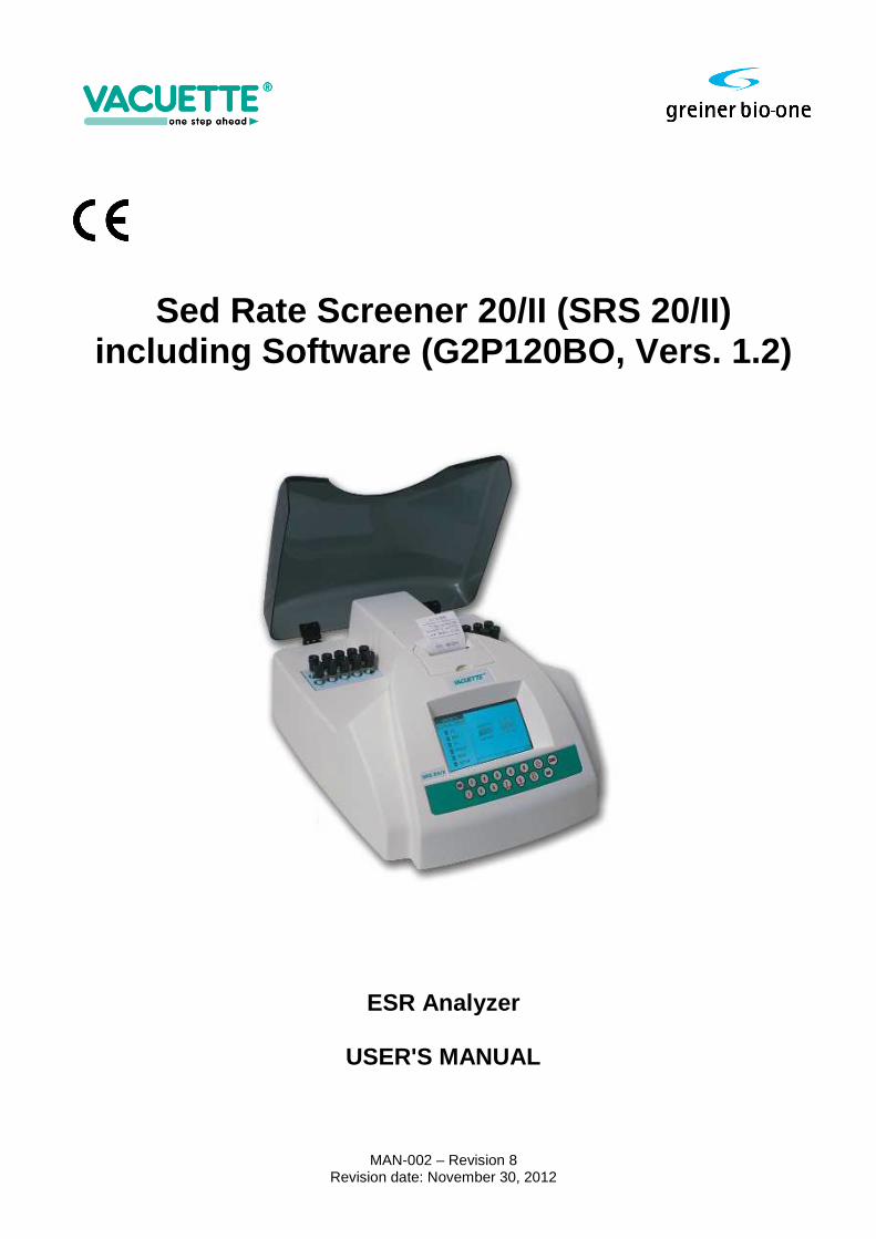
Sed Rate Screener 20/II (SRS 20/II) including Software (G2P120BO, Vers. 1.2)
ESR Analyzer
USER'S MANUAL
MAN-002 – Revision 8 Revision date: November 30, 2012
SRS 20/II USER MANUAL page 2 of 37
This user manual follows the directions as prescribed by the CEN/TC 140 recommendations for in -vitro diagnostic instruments (EN ISO 18113-3:2009): INSTRUMENT NAME: Sed Rate Screener 20/II (SRS 20/II)
including Software (G2P120BO, Vers. 1.2) Short cut name: SRS 20/II Automatic Sed-Rate analyzer, 20 measuring channels .
Greiner Bio-One GmbH Bad Haller Straße 32 A-4550 Kremsmünster AUSTRIA Tel.: +43 (0)7583 6791-0 Fax.: +43 (0)7583 6318 Mail: [email protected] PLEASE READ THIS ENTIRE PRODUCT MANUAL BEFORE USING THE INSTRUMENT FOR THE FIRST TIME.
SRS 20/II USER MANUAL page 3 of 37
CONTENTS
1. INTRODUCTION ................................................................................................................................................... 5
1.1 INTENDED USE ............................................................................................................................................................... 5
2. POTENTIAL DANGERS AND SAFETY PRECAUTIONS .................................................................................... 5
2.1 USER PRECAUTIONS ...................................................................................................................................................... 5
2.1.1 User Identification .......................................................................................................................................... 5
2.2 ELECTRICAL EQUIPMENT ............................................................................................................................................... 5
2.3 MECHANICAL EQUIPMENT ............................................................................................................................................. 5
2.4 BIOHAZARDOUS MATERIAL............................................................................................................................................ 5
2.4.1 Human samples .............................................................................................................................................. 6
2.4.2 Waste solution and solid waste ...................................................................................................................... 6
2.5 NOTES ON SAFETY MEASURE ......................................................................................................................................... 6
2.6 DISPOSAL AND RECYCLING ......................................................................................................................................... 6
2.7 BIO-HAZARDOUS PARTS DISPOSAL ............................................................................................................................... 6 2.8 ADDITIONAL PRECAUTIONS .......................................................................................................................................... 7
3. INSTALLATION .......................................................................................................................................................... 8
3.1 POSITIONING OF THE ANALYZER .................................................................................................................................... 8
3.2 POWER ON ..................................................................................................................................................................... 8 3.3 INSTRUMENT SET UP ...................................................................................................................................................... 9
3.4 INSTRUMENT STAND-BY ................................................................................................................................................ 9
4. SYSTEM DESCRIPTION ......................................................................................................................................... 10
4.1 SAMPLE COLLECTING ................................................................................................................................................... 10
4.2 LABELING .................................................................................................................................................................... 10 4.3 TEST TUBES HANDLING ............................................................................................................................................... 11
4.4 SAMPLE MIXING ........................................................................................................................................................... 11 4.5 SAMPLE INSERTION ...................................................................................................................................................... 12
4.6 SYMBOLS IDENTIFICATION ........................................................................................................................................... 12
4.7 PERFORMANCE CRITERIA AND LIMITATIONS ................................................................................................................ 13 4.8 FUNCTIONAL DIAGRAM ............................................................................................................................................... 14
5. SOFTWARE ............................................................................................................................................................... 15
5.1 ID: ( FUNCTION: 1) ...................................................................................................................................................... 15
5.2 MEM: (FUNCTION: 2) .................................................................................................................................................. 15
5.3 QC: (FUNCTION: 3) ...................................................................................................................................................... 16
5.4 PRINT: (FUNCTION: 4) ................................................................................................................................................ 18
5.5 HOST: (FUNCTION: 5) ................................................................................................................................................. 19
5.6 SETUP: (FUNCTION: 6) ............................................................................................................................................... 19
5.7 PRINTER PAPER FEED: .................................................................................................................................................. 20
6. RESULTS .................................................................................................................................................................... 21
6.1 SRS 20/II CAN GIVE DIFFERENT KINDS OF RESULTS: .................................................................................................... 21
6.2 RESULTS CORRECTION TO 18°C ................................................................................................................................... 21
7. WARNINGS INFORMATION ................................................................................................................................. 22
7.1 “ LEV “ (LEVEL ERROR) ................................................................................................................................................ 22
7.2 “ REM “ (SAMPLE REMOVED ERROR) ............................................................................................................................ 22 7.3 SYSTEM ERROR WARNINGS ......................................................................................................................................... 22
8. MAINTENANCE ........................................................................................................................................................ 22
8.1 CLEANING AND DECONTAMINATION INSTRUCTIONS .................................................................................................... 22
8.2 PAPER REPLACEMENT INSTRUCTIONS .......................................................................................................................... 24 8.3 PERIODIC TEST ............................................................................................................................................................. 25

SRS 20/II USER MANUAL page 4 of 37
9. TROUBLESHOOTING GUIDE ............................................................................................................................... 26
10. TECHNICAL SPECIFICATION SRS 20/II .......................................................................................................... 28
11. PACKAGING INFORMATION ............................................................................................................................. 30
APPENDIX...................................................................................................................................................................... 31
A. THEORETICAL INFORMATION ............................................................................................................................. 31
A.1 Westergren Method ........................................................................................................................................... 31
A.2 Variations of ESR ............................................................................................................................................. 31
B. PRINTER TYPES PROTOCOL DESCRIPTION ........................................................................................................ 33 C. HOST CONNECTION PROTOCOL ........................................................................................................................... 34

SRS 20/II USER MANUAL page 5 of 37
1. INTRODUCTION 1.1 Intended use The SRS 20/II ESR analyzer is an automatic instrument controlled by a microprocessor and exclusively employed for the in vitro diagnostic determination (IVD) of erythrocyte sedimentation rate (ESR). It constantly and simultaneously scans 20 test tubes, which are custom-made for ESR analysis. The SRS 20/II follows the sedimentation of each sample independently, memorizing levels for the whole period of analysis. Every attempt to use the SRS 20/II ESR analyzer with a purpose different from the intended use, must be considered improper. 2. POTENTIAL DANGERS AND SAFETY PRECAUTIONS 2.1 User Precautions Before beginning the use of the analyzer, the operator must know the rules for handling potentially infectious materials and for handling Electro-mechanical systems. 2.1.1 User Identification This ESR analyzer is intended for professional use only. The operator must be trained for working in laboratory using hazardous materials and professional equipment. The use of this ESR analyzer by a not trained operator is considered an improper use. 2.2 Electrical equipment As all electrical equipment, the power supply is a potential source of danger. Please avoid handling electrical parts before disconnecting them from the power supply. Never carry out maintenance on the instrument when it is under electrical tension. Until the instrument is packaged, as supplied, the operator is protected against electric shock. Pay attention to the following electrical parts: the power supply and the printer. The SRS 100/II analyzer, is powered by low voltage, and it doesn’t present the same dangers of the equipment’s powered by an electrical line. Even though it has a voltage elevator circuit inside, and it could provoke strong electrical shocks, it is not dangerous for the service assistance personnel. We suggest to disconnect the power supply every time a technical operator make instrument maintenance. 2.3 Mechanical equipment For the mechanical part of the analyzer, we suggest to not open the machine before having disconnected it from the power supply. If the power is on, it is not dangerous for the operator, but instrument would damage if brought into contact with the parts in movement. 2.4 Biohazardous material As with all in vitro diagnostic equipment, patient samples and quality control (QC) products that are assayed on this system, should be treated as potentially bio-hazardous. All materials should be handled according to your facility's biohazard procedure. Always wear the personal protective equipment recommended by your facility when using the analyzer.

SRS 20/II USER MANUAL page 6 of 37
2.4.1 Human samples Always wear gloves and eye protective glasses when handling human samples. Treat all samples as potentially bio-hazardous and infectious. If any sample is spilt on the instrument, utilize the correct personal protective equipment (PPE-gloves, lab coat, etc.), wipe it up immediately and clean the contaminated surface with a disinfectant (e.g.sodium hypochlorite 0.5%) solution. 2.4.2 Waste solution and solid waste Avoid direct contact with waste solution and/or solid waste. Both should be handled as potentially bio-hazardous. Dispose of waste solution and/or solid waste according to local governmental regulations. 2.5 Notes on safety measure Please pay attention to the sample collection. The vacuum test tubes used for this instrument, have been studied to draw the right level of blood. To fill the test tube with a higher volume of blood, could cause a serious infection risk for tube leakage. Furthermore the leakage could damage the inner optical part of the instrument and annul the guarantee. 2.6 Disposal And Recycling Herewith we declare that this instrument is subject to the European Directive 2002/96/EC (RAEE Directive) and 2003/108/EC. Therefore the instrument must be disposed separately, not as urban waste and delivered to the specific collection centre in accordance with the Directive 2002/96/EC and 2003/108/EC. The user may request that the supplier collect the instrument for correct disposal, if a new instrument is ordered. 2.7 Bio-Hazardous Parts Disposal All parts which have a direct contact with samples must be disposed as POTENTIALLY INFECTIOUS. Follow local regulations.

SRS 20/II USER MANUAL page 7 of 37
2.8 Additional Precautions The following symbols are placed on the instrument to assure correct usage:
Attention: read use instruction
For in vitro diagnostic use only
ELECTROSTATIC DISCHARGE SENSITIVE DEVICE (ESDS): The device could be damaged by electrostatic potentials
BIOHAZARD RISK Adopt protective measures to avoid any contamination (gloves, glasses etc…)
DO NOT DISPOSE The instrument cannot be disposed as urban waste
DC DIRECT CURRENT
SRS 20/II USER MANUAL page 8 of 37
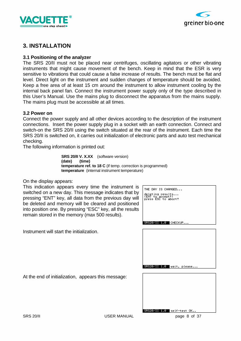
3. INSTALLATION 3.1 Positioning of the analyzer The SRS 20/II must not be placed near centrifuges, oscillating agitators or other vibrating instruments that might cause movement of the bench. Keep in mind that the ESR is very sensitive to vibrations that could cause a false increase of results. The bench must be flat and level. Direct light on the instrument and sudden changes of temperature should be avoided. Keep a free area of at least 15 cm around the instrument to allow instrument cooling by the internal back panel fan. Connect the instrument power supply only of the type described in this User’s Manual. Use the mains plug to disconnect the apparatus from the mains supply. The mains plug must be accessible at all times. 3.2 Power on Connect the power supply and all other devices according to the description of the instrument connections. Insert the power supply plug in a socket with an earth connection. Connect and switch-on the SRS 20/II using the switch situated at the rear of the instrument. Each time the SRS 20/II is switched on, it carries out initialization of electronic parts and auto test mechanical checking. The following information is printed out: SRS 20/II V. X.XX (software version) (date) (time) temperature ref. to 18 C (if temp. correction is programmed) temperature (internal instrument temperature) On the display appears: This indication appears every time the instrument is switched on a new day. This message indicates that by pressing “ENT” key, all data from the previous day will be deleted and memory will be cleared and positioned into position one. By pressing “ESC” key, all the results remain stored in the memory (max 500 results). Instrument will start the initialization. At the end of initialization, appears this message:
SRS 20/II USER MANUAL page 9 of 37
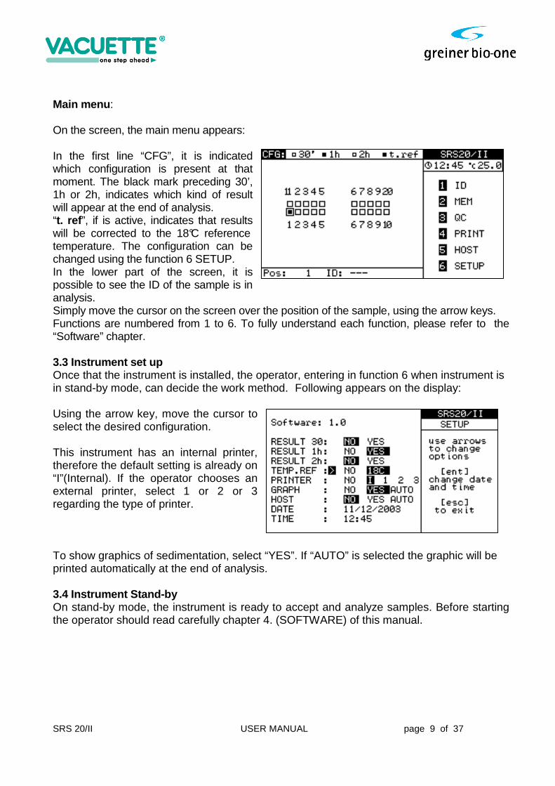
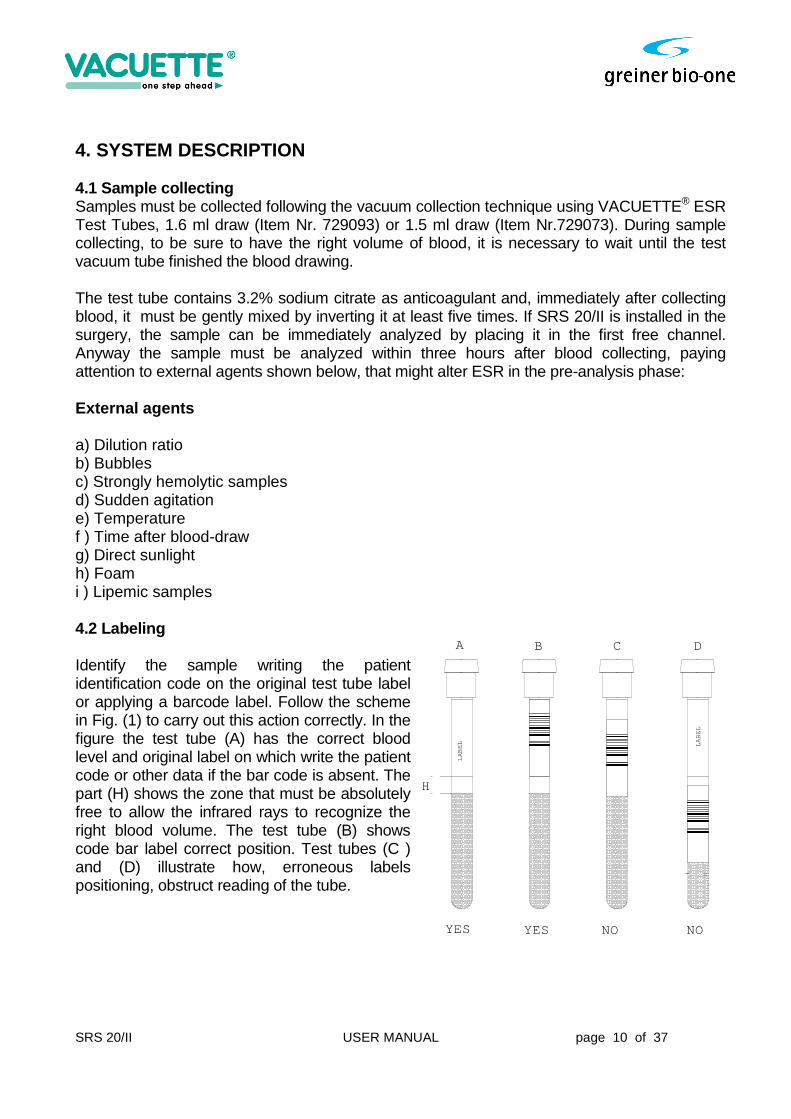
Main menu : On the screen, the main menu appears: In the first line “CFG”, it is indicated which configuration is present at that moment. The black mark preceding 30’, 1h or 2h, indicates which kind of result will appear at the end of analysis. “t. ref ”, if is active, indicates that results will be corrected to the 18°C reference temperature. The configuration can be changed using the function 6 SETUP. In the lower part of the screen, it is possible to see the ID of the sample is in analysis. Simply move the cursor on the screen over the position of the sample, using the arrow keys. Functions are numbered from 1 to 6. To fully understand each function, please refer to the “Software” chapter. 3.3 Instrument set up Once that the instrument is installed, the operator, entering in function 6 when instrument is in stand-by mode, can decide the work method. Following appears on the display: Using the arrow key, move the cursor to select the desired configuration. This instrument has an internal printer, therefore the default setting is already on “I”(Internal). If the operator chooses an external printer, select 1 or 2 or 3 regarding the type of printer. To show graphics of sedimentation, select “YES”. If “AUTO” is selected the graphic will be printed automatically at the end of analysis. 3.4 Instrument Stand-by On stand-by mode, the instrument is ready to accept and analyze samples. Before starting the operator should read carefully chapter 4. (SOFTWARE) of this manual.
SRS 20/II USER MANUAL page 10 of 37
LA
BE
L LA
BE
L
A B C D
YES YES NO NO
H
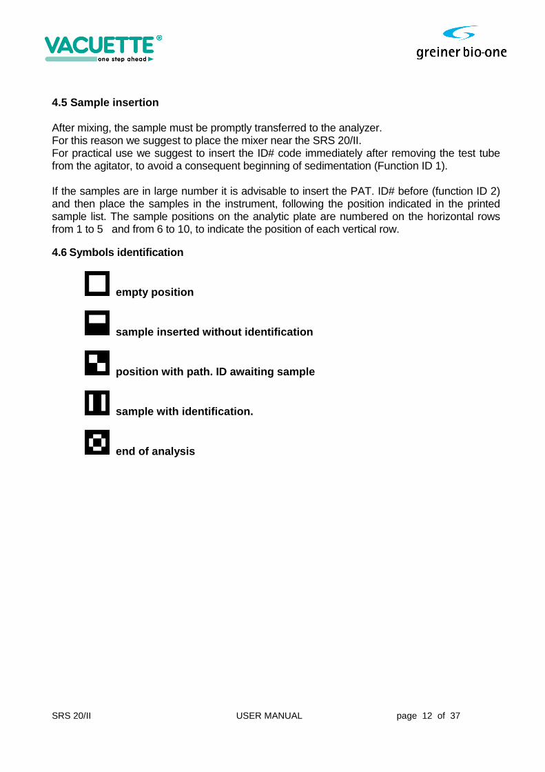
4. SYSTEM DESCRIPTION 4.1 Sample collecting Samples must be collected following the vacuum collection technique using VACUETTE® ESR Test Tubes, 1.6 ml draw (Item Nr. 729093) or 1.5 ml draw (Item Nr.729073). During sample collecting, to be sure to have the right volume of blood, it is necessary to wait until the test vacuum tube finished the blood drawing. The test tube contains 3.2% sodium citrate as anticoagulant and, immediately after collecting blood, it must be gently mixed by inverting it at least five times. If SRS 20/II is installed in the surgery, the sample can be immediately analyzed by placing it in the first free channel. Anyway the sample must be analyzed within three hours after blood collecting, paying attention to external agents shown below, that might alter ESR in the pre-analysis phase: External agents a) Dilution ratio b) Bubbles c) Strongly hemolytic samples d) Sudden agitation e) Temperature f ) Time after blood-draw g) Direct sunlight h) Foam i ) Lipemic samples 4.2 Labeling Identify the sample writing the patient identification code on the original test tube label or applying a barcode label. Follow the scheme in Fig. (1) to carry out this action correctly. In the figure the test tube (A) has the correct blood level and original label on which write the patient code or other data if the bar code is absent. The part (H) shows the zone that must be absolutely free to allow the infrared rays to recognize the right blood volume. The test tube (B) shows code bar label correct position. Test tubes (C ) and (D) illustrate how, erroneous labels positioning, obstruct reading of the tube.

SRS 20/II USER MANUAL page 11 of 37
4.3 Test Tubes handling Handling requirements
The vacuum test tube needs to be inserted properly into its holder to obtain the automatic draw of 1.5 ml or 1.6 ml of blood, required by the analysis. Tubes are removed from the holder only after the draw has been completely terminated, i.e. the required amount of blood for the analysis has been properly evacuated. In case of an incorrect blood collection, the SRS 20/II will refuse to analyze the sample, indicating “lev” (Level Error), because the Sedimentation Rate result would be incorrect, due to an erroneous ratio with the anticoagulant present in the tube. All vacuum test tubes need to be mixed gently immediately after the blood collection, to ensure the proper mixing of the sodium citrate with the freshly drawn blood. Therefore, tubes are gently turned inverted five times, ensuring that the air-bubble floats from one end of the tube to the other. It is essential that before ESR determination is started, the sample tube is carefully re-mixed ten times, according to the procedure as described above. Storage requirements Store the test tubes at room temperature, always below 30°C. Never place the bench top tube container (50 tubes) near a heating device or close to a window where direct sunlight could create unwanted heating effects. 4.4 Sample mixing If it is not possible to analyze the sample immediately after sample-collection, it must be mixed delicately by inverting for at least five minutes before putting the sample into the instrument. Use a rotating laboratory agitator or a dedicate agitator (optional part: VACUETTE® MultiMixer Item Nr. 836577). The recommended rpm-value for mixing is 15-20 RPM. If manually mixed, the samples must be turned inverted at least 10 times, ensuring that the air-bubble floats from one end of the tube to the other.
SRS 20/II USER MANUAL page 12 of 37
4.5 Sample insertion After mixing, the sample must be promptly transferred to the analyzer. For this reason we suggest to place the mixer near the SRS 20/II. For practical use we suggest to insert the ID# code immediately after removing the test tube from the agitator, to avoid a consequent beginning of sedimentation (Function ID 1). If the samples are in large number it is advisable to insert the PAT. ID# before (function ID 2) and then place the samples in the instrument, following the position indicated in the printed sample list. The sample positions on the analytic plate are numbered on the horizontal rows from 1 to 5 and from 6 to 10, to indicate the position of each vertical row. 4.6 Symbols identification
empty position
sample inserted without identification
position with path. ID awaiting sample
sample with identification.
end of analysis

SRS 20/II USER MANUAL page 13 of 37
4.7 Performance criteria and limitations
1) PERFORMANCE CRITERIA A. Mechanical / Optical precision of detection : +/- 0.2 mm B. Variability Coefficient of analysis : C.V. < 5 % (sample depending) C. Automatic temperature conversion to 18°C. ( Manley table ) : Accepted range: 15° - 32° C. D. Acceptable range for blood drawing : -10 + 4 mm from normal E. Max 10 Measuring points : Intervals of 3 minutes F. Measuring range : 1 - 140 mm/h G. Memory capacity : Up to 500 results H. Patient identification limitation : Up to 12 digits 2) LIMITATIONS
A. Strongly lipemic or hemolytic samples may alter reading capability. B. Sed rate values > 140 mm/h will be indicated with this mark only. C. Temperatures outside the given range will be accepted as 15 ° min and 32° max
SRS 20/II USER MANUAL page 14 of 37
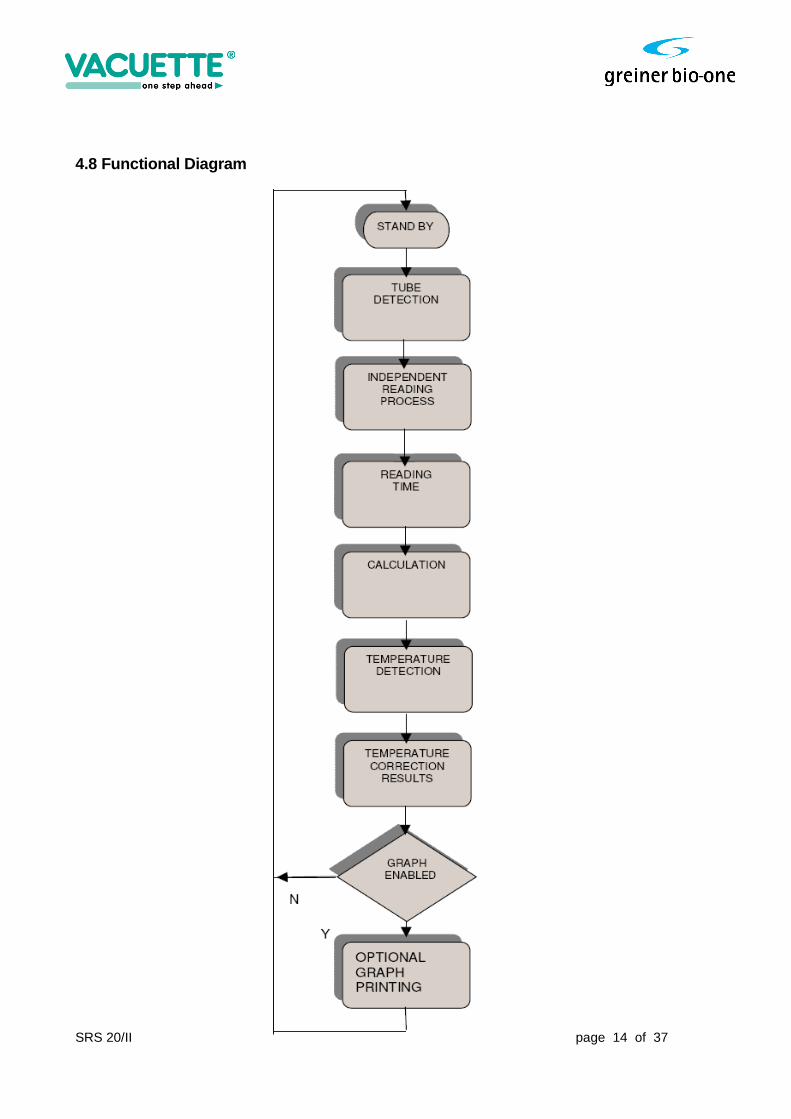
4.8 Functional Diagram
SRS 20/II USER MANUAL page 15 of 37
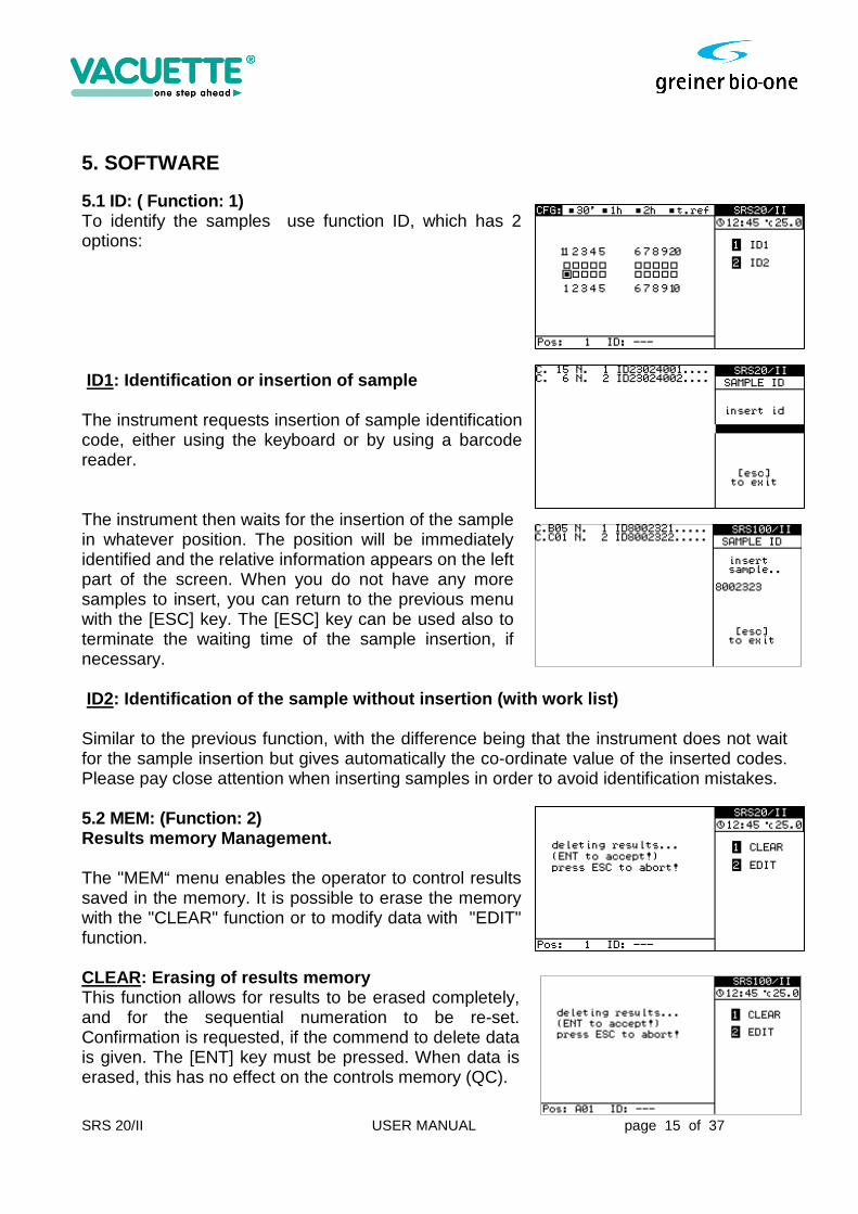
5. SOFTWARE 5.1 ID: ( Function: 1) To identify the samples use function ID, which has 2 options: ID1: Identification or insertion of sample The instrument requests insertion of sample identification code, either using the keyboard or by using a barcode reader. The instrument then waits for the insertion of the sample in whatever position. The position will be immediately identified and the relative information appears on the left part of the screen. When you do not have any more samples to insert, you can return to the previous menu with the [ESC] key. The [ESC] key can be used also to terminate the waiting time of the sample insertion, if necessary. ID2: Identification of the sample without insertio n (with work list) Similar to the previous function, with the difference being that the instrument does not wait for the sample insertion but gives automatically the co-ordinate value of the inserted codes. Please pay close attention when inserting samples in order to avoid identification mistakes. 5.2 MEM: (Function: 2) Results memory Management. The "MEM“ menu enables the operator to control results saved in the memory. It is possible to erase the memory with the "CLEAR" function or to modify data with "EDIT" function. CLEAR: Erasing of results memory This function allows for results to be erased completely, and for the sequential numeration to be re-set. Confirmation is requested, if the commend to delete data is given. The [ENT] key must be pressed. When data is erased, this has no effect on the controls memory (QC).
SRS 20/II USER MANUAL page 16 of 37
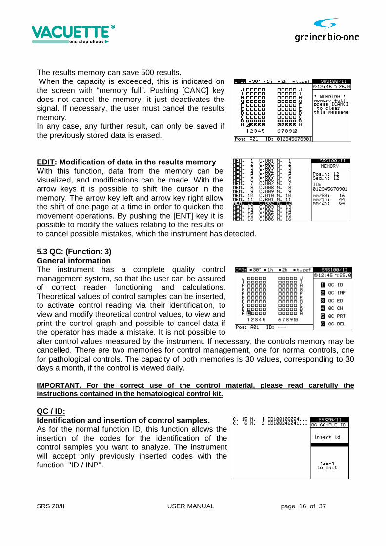
The results memory can save 500 results. When the capacity is exceeded, this is indicated on the screen with “memory full”. Pushing [CANC] key does not cancel the memory, it just deactivates the signal. If necessary, the user must cancel the results memory. In any case, any further result, can only be saved if the previously stored data is erased. EDIT: Modification of data in the results memory With this function, data from the memory can be visualized, and modifications can be made. With the arrow keys it is possible to shift the cursor in the memory. The arrow key left and arrow key right allow the shift of one page at a time in order to quicken the movement operations. By pushing the [ENT] key it is possible to modify the values relating to the results or to cancel possible mistakes, which the instrument has detected. 5.3 QC: (Function: 3) General information The instrument has a complete quality control management system, so that the user can be assured of correct reader functioning and calculations. Theoretical values of control samples can be inserted, to activate control reading via their identification, to view and modify theoretical control values, to view and print the control graph and possible to cancel data if the operator has made a mistake. It is not possible to alter control values measured by the instrument. If necessary, the controls memory may be cancelled. There are two memories for control management, one for normal controls, one for pathological controls. The capacity of both memories is 30 values, corresponding to 30 days a month, if the control is viewed daily. IMPORTANT. For the correct use of the control mater ial, please read carefully the instructions contained in the hematological control kit. QC / ID: Identification and insertion of control samples. As for the normal function ID, this function allows the insertion of the codes for the identification of the control samples you want to analyze. The instrument will accept only previously inserted codes with the function "ID / INP".
SRS 20/II USER MANUAL page 17 of 37
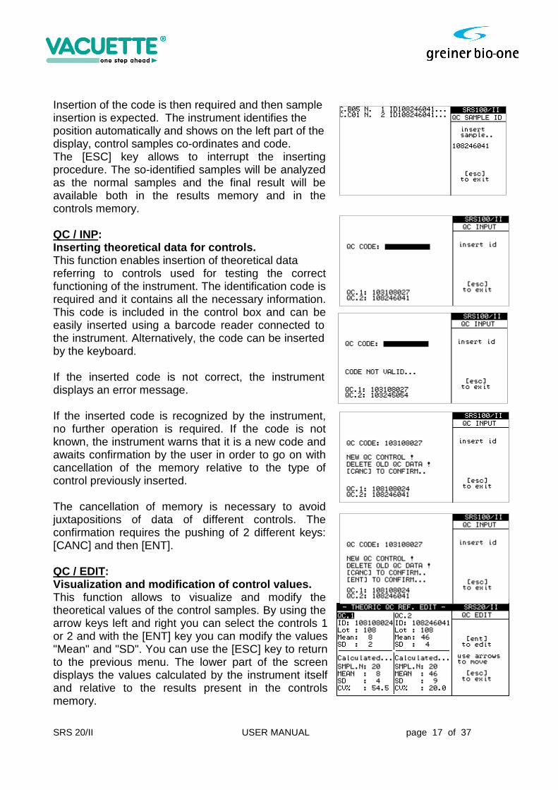
Insertion of the code is then required and then sample insertion is expected. The instrument identifies the position automatically and shows on the left part of the display, control samples co-ordinates and code. The [ESC] key allows to interrupt the inserting procedure. The so-identified samples will be analyzed as the normal samples and the final result will be available both in the results memory and in the controls memory. QC / INP: Inserting theoretical data for controls. This function enables insertion of theoretical data referring to controls used for testing the correct functioning of the instrument. The identification code is required and it contains all the necessary information. This code is included in the control box and can be easily inserted using a barcode reader connected to the instrument. Alternatively, the code can be inserted by the keyboard. If the inserted code is not correct, the instrument displays an error message. If the inserted code is recognized by the instrument, no further operation is required. If the code is not known, the instrument warns that it is a new code and awaits confirmation by the user in order to go on with cancellation of the memory relative to the type of control previously inserted. The cancellation of memory is necessary to avoid juxtapositions of data of different controls. The confirmation requires the pushing of 2 different keys: [CANC] and then [ENT]. QC / EDIT: Visualization and modification of control values. This function allows to visualize and modify the theoretical values of the control samples. By using the arrow keys left and right you can select the controls 1 or 2 and with the [ENT] key you can modify the values "Mean" and "SD". You can use the [ESC] key to return to the previous menu. The lower part of the screen displays the values calculated by the instrument itself and relative to the results present in the controls memory.
SRS 20/II USER MANUAL page 18 of 37
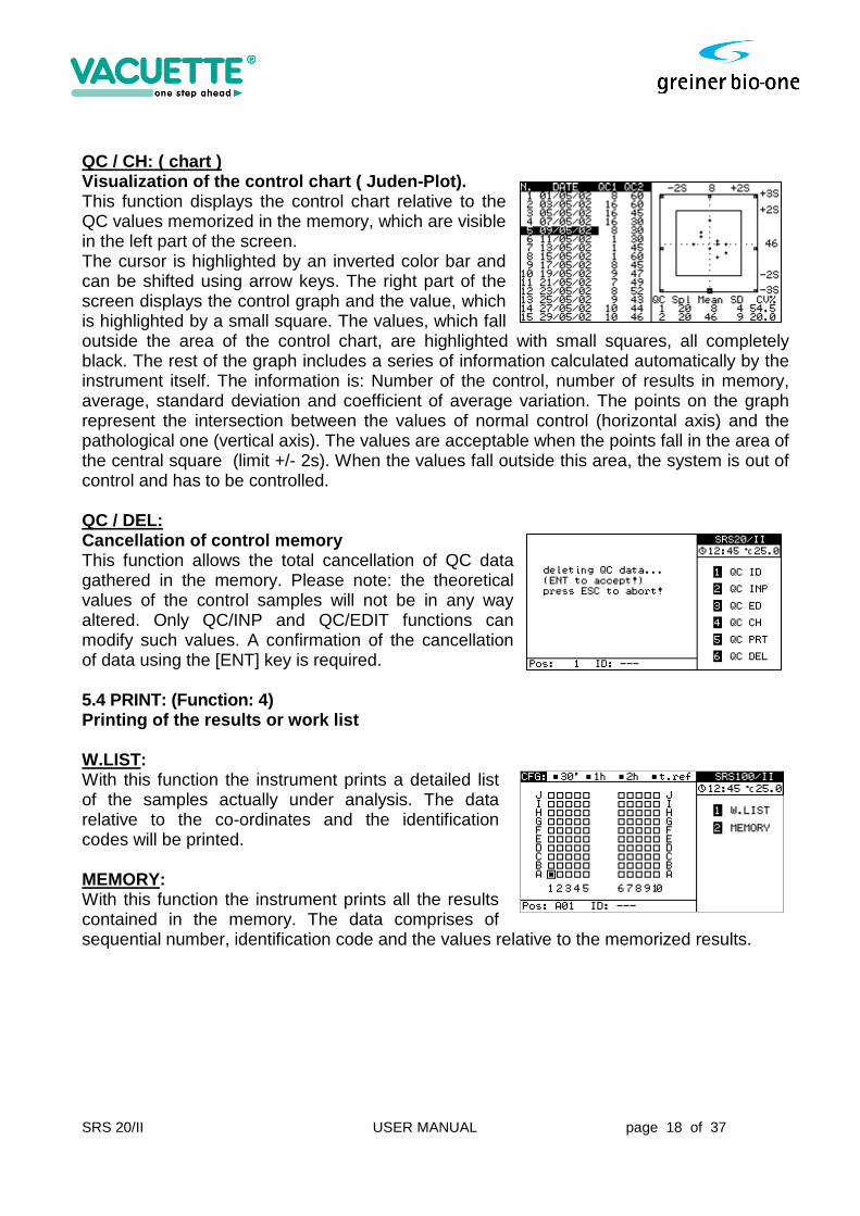
QC / CH: ( chart ) Visualization of the control chart ( Juden-Plot). This function displays the control chart relative to the QC values memorized in the memory, which are visible in the left part of the screen. The cursor is highlighted by an inverted color bar and can be shifted using arrow keys. The right part of the screen displays the control graph and the value, which is highlighted by a small square. The values, which fall outside the area of the control chart, are highlighted with small squares, all completely black. The rest of the graph includes a series of information calculated automatically by the instrument itself. The information is: Number of the control, number of results in memory, average, standard deviation and coefficient of average variation. The points on the graph represent the intersection between the values of normal control (horizontal axis) and the pathological one (vertical axis). The values are acceptable when the points fall in the area of the central square (limit +/- 2s). When the values fall outside this area, the system is out of control and has to be controlled. QC / DEL: Cancellation of control memory This function allows the total cancellation of QC data gathered in the memory. Please note: the theoretical values of the control samples will not be in any way altered. Only QC/INP and QC/EDIT functions can modify such values. A confirmation of the cancellation of data using the [ENT] key is required. 5.4 PRINT: (Function: 4) Printing of the results or work list W.LIST: With this function the instrument prints a detailed list of the samples actually under analysis. The data relative to the co-ordinates and the identification codes will be printed. MEMORY: With this function the instrument prints all the results contained in the memory. The data comprises of sequential number, identification code and the values relative to the memorized results.
SRS 20/II USER MANUAL page 19 of 37
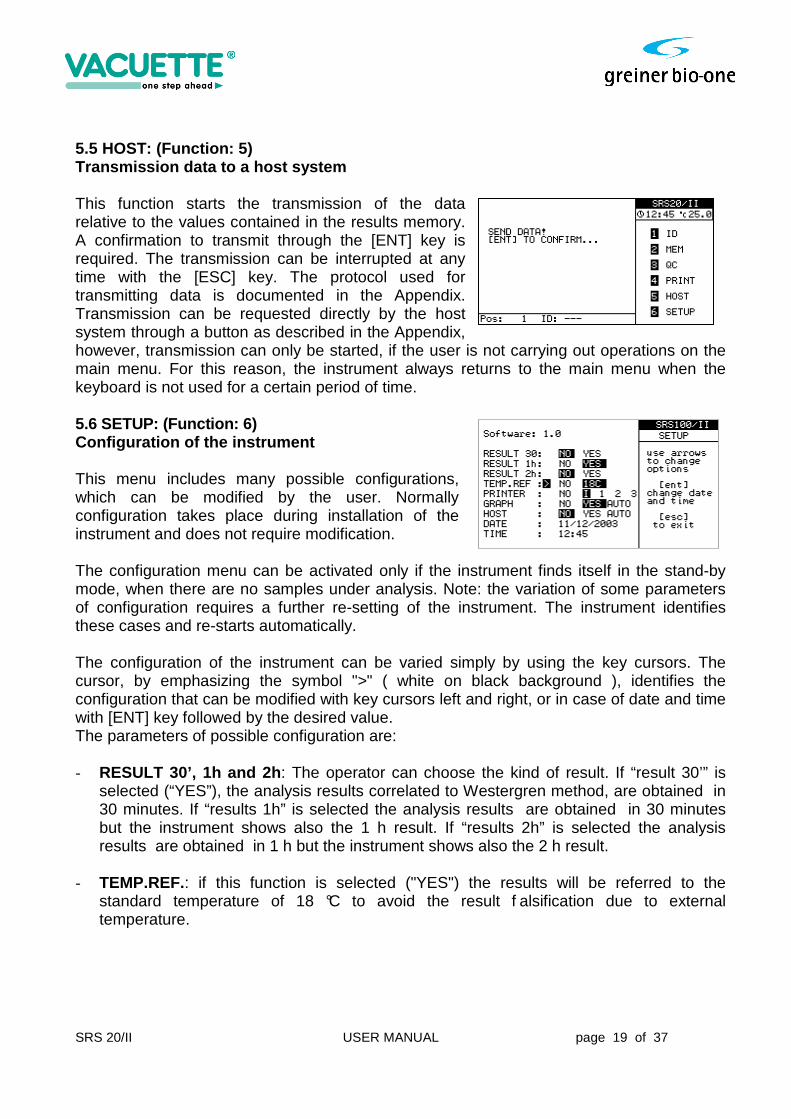
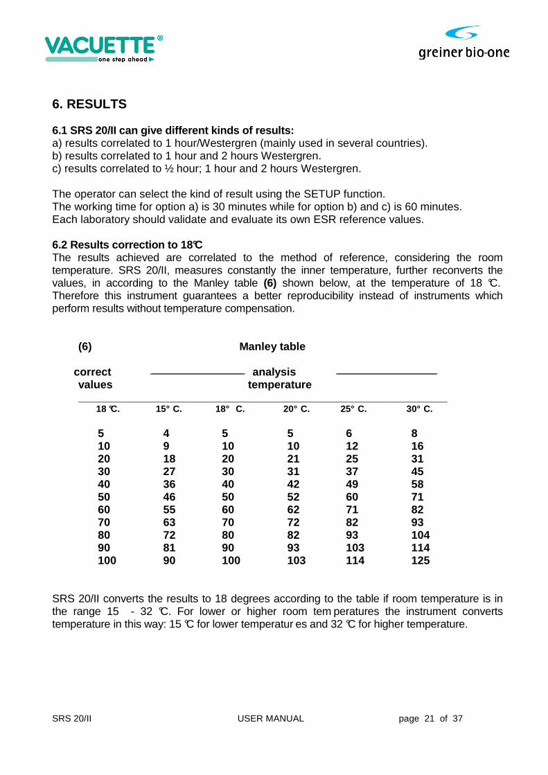
5.5 HOST: (Function: 5) Transmission data to a host system This function starts the transmission of the data relative to the values contained in the results memory. A confirmation to transmit through the [ENT] key is required. The transmission can be interrupted at any time with the [ESC] key. The protocol used for transmitting data is documented in the Appendix. Transmission can be requested directly by the host system through a button as described in the Appendix, however, transmission can only be started, if the user is not carrying out operations on the main menu. For this reason, the instrument always returns to the main menu when the keyboard is not used for a certain period of time. 5.6 SETUP: (Function: 6) Configuration of the instrument This menu includes many possible configurations, which can be modified by the user. Normally configuration takes place during installation of the instrument and does not require modification. The configuration menu can be activated only if the instrument finds itself in the stand-by mode, when there are no samples under analysis. Note: the variation of some parameters of configuration requires a further re-setting of the instrument. The instrument identifies these cases and re-starts automatically. The configuration of the instrument can be varied simply by using the key cursors. The cursor, by emphasizing the symbol ">" ( white on black background ), identifies the configuration that can be modified with key cursors left and right, or in case of date and time with [ENT] key followed by the desired value. The parameters of possible configuration are: - RESULT 30’, 1h and 2h : The operator can choose the kind of result. If “result 30’” is
selected (“YES”), the analysis results correlated to Westergren method, are obtained in 30 minutes. If “results 1h” is selected the analysis results are obtained in 30 minutes but the instrument shows also the 1 h result. If “results 2h” is selected the analysis results are obtained in 1 h but the instrument shows also the 2 h result.
- TEMP.REF.: if this function is selected ("YES") the results will be referred to the
standard temperature of 18 °C to avoid the result f alsification due to external temperature.

SRS 20/II USER MANUAL page 20 of 37
- PRINTER: This function permits the operator to choose different printing (see Appendix). In the default setting is selected the internal printer (“I”), which is incorporated in the instrument. Any other selection implies an external printer connected to the instrument.
- GRAPH: The option "NO" deactivates sedimentation curve visualization. In this way the
instrument will not analyze the intermediate level every 3 minutes and so the life of the mechanical and electronic parts subject to movement are prolonged. The option "YES" permits management of the curve, which can be viewed and printed by pushing the button [ENT] from the main menu. The option "AUTO" activates the automatic printing of the sedimentation graph together with the printing of the results of the samples.
- HOST: If the option "NO" is chosen, when the operator switch on the instrument, it
doesn’t control the HOST system connection but the function "HOST“ still remains available. If the option "YES" is chosen, the instrument makes the initial control of HOST system connection. The system HOST must be connected and ready to receive the data. The option "AUTO" means that as soon as analysis is finished, data will be transmitted immediately to the host. In any case will be transmitted only the results and data concerning the sample identification.
- DATE / TIME: Time is printed, memorized and transmitted to the host. With this function
the operator can set the internal clock. 5.7 Printer paper feed: When the instrument show the main menu, the printer paper can be advanced by pressing the “CANC” key on the keyboard. Warning , do not pull out the paper by hands. If the printer paper need to be replaced please follow instructions explained at the end of this manual on “Paper Replacement Instructions ” appendix.
SRS 20/II USER MANUAL page 21 of 37
6. RESULTS 6.1 SRS 20/II can give different kinds of results: a) results correlated to 1 hour/Westergren (mainly used in several countries). b) results correlated to 1 hour and 2 hours Westergren. c) results correlated to ½ hour; 1 hour and 2 hours Westergren. The operator can select the kind of result using the SETUP function. The working time for option a) is 30 minutes while for option b) and c) is 60 minutes. Each laboratory should validate and evaluate its own ESR reference values. 6.2 Results correction to 18°C The results achieved are correlated to the method of reference, considering the room temperature. SRS 20/II, measures constantly the inner temperature, further reconverts the values, in according to the Manley table (6) shown below, at the temperature of 18 °C. Therefore this instrument guarantees a better reproducibility instead of instruments which perform results without temperature compensation. (6) Manley table correct analysis values temperature ____________________________________________________________ 18 °C. 15° C. 18° C. 20° C. 25° C. 30° C. 5 4 5 5 6 8 10 9 10 10 12 16 20 18 20 21 25 31 30 27 30 31 37 45 40 36 40 42 49 58 50 46 50 52 60 71 60 55 60 62 71 82 70 63 70 72 82 93 80 72 80 82 93 104 90 81 90 93 103 114 100 90 100 103 114 125 SRS 20/II converts the results to 18 degrees according to the table if room temperature is in the range 15 - 32 °C. For lower or higher room tem peratures the instrument converts temperature in this way: 15 °C for lower temperatur es and 32 °C for higher temperature.
SRS 20/II USER MANUAL page 22 of 37
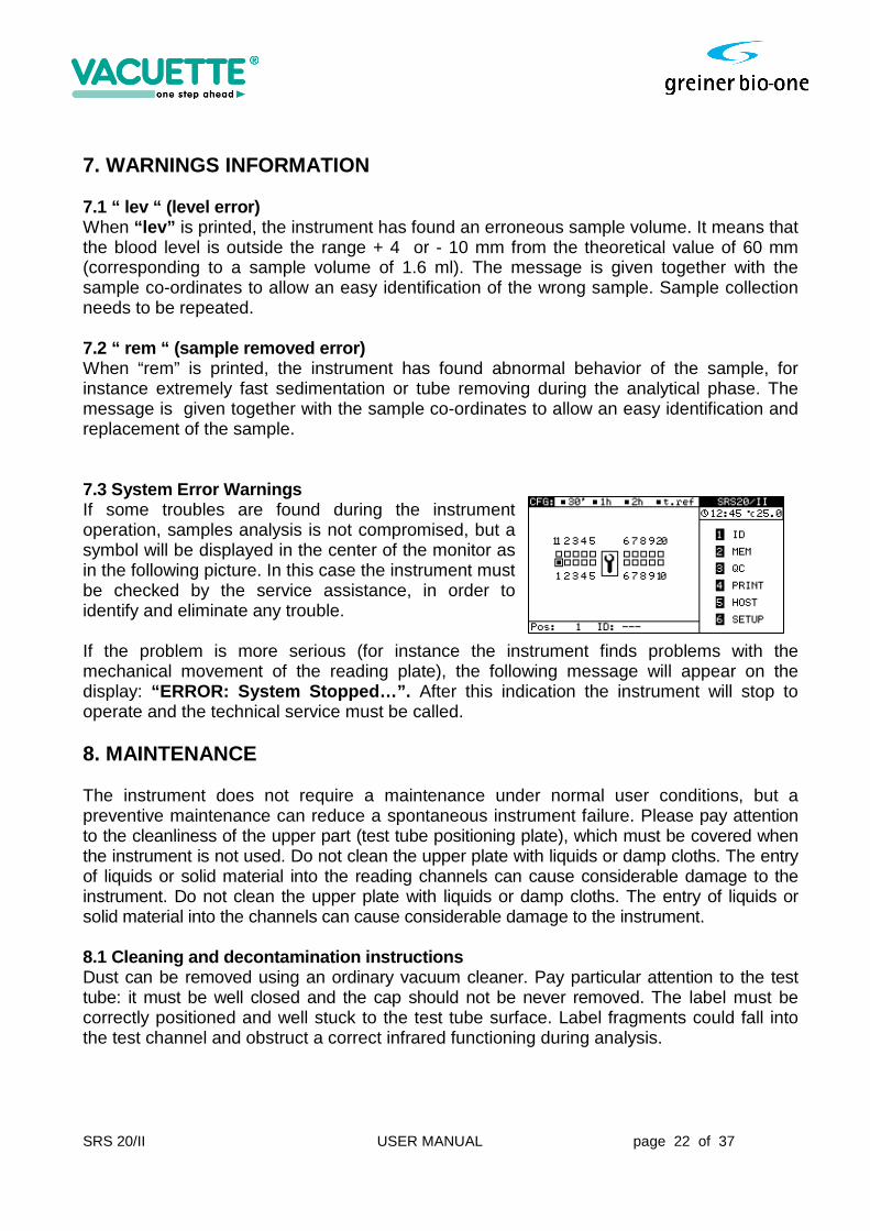
7. WARNINGS INFORMATION 7.1 “ lev “ (level error) When “lev” is printed, the instrument has found an erroneous sample volume. It means that the blood level is outside the range + 4 or - 10 mm from the theoretical value of 60 mm (corresponding to a sample volume of 1.6 ml). The message is given together with the sample co-ordinates to allow an easy identification of the wrong sample. Sample collection needs to be repeated. 7.2 “ rem “ (sample removed error) When “rem” is printed, the instrument has found abnormal behavior of the sample, for instance extremely fast sedimentation or tube removing during the analytical phase. The message is given together with the sample co-ordinates to allow an easy identification and replacement of the sample. 7.3 System Error Warnings If some troubles are found during the instrument operation, samples analysis is not compromised, but a symbol will be displayed in the center of the monitor as in the following picture. In this case the instrument must be checked by the service assistance, in order to identify and eliminate any trouble. If the problem is more serious (for instance the instrument finds problems with the mechanical movement of the reading plate), the following message will appear on the display: “ERROR: System Stopped…”. After this indication the instrument will stop to operate and the technical service must be called. 8. MAINTENANCE The instrument does not require a maintenance under normal user conditions, but a preventive maintenance can reduce a spontaneous instrument failure. Please pay attention to the cleanliness of the upper part (test tube positioning plate), which must be covered when the instrument is not used. Do not clean the upper plate with liquids or damp cloths. The entry of liquids or solid material into the reading channels can cause considerable damage to the instrument. Do not clean the upper plate with liquids or damp cloths. The entry of liquids or solid material into the channels can cause considerable damage to the instrument. 8.1 Cleaning and decontamination instructions Dust can be removed using an ordinary vacuum cleaner. Pay particular attention to the test tube: it must be well closed and the cap should not be never removed. The label must be correctly positioned and well stuck to the test tube surface. Label fragments could fall into the test channel and obstruct a correct infrared functioning during analysis.

SRS 20/II USER MANUAL page 23 of 37
1. Wipe potentially contaminated areas of the SRS 100/II with a cloth or paper towel wet with 1% bleach solution (Solution A). Solution A (about 1%): 200 ml hypochloride and 800 ml of reagent grade water.
2. Let solution set for at least 15 minutes. 3. Wipe Solution A from areas. 4. Wipe areas again with cloth or paper towel with reagent grade water to remove the
Solution A. 5. Dry areas thoroughly.
SRS 20/II USER MANUAL page 24 of 37
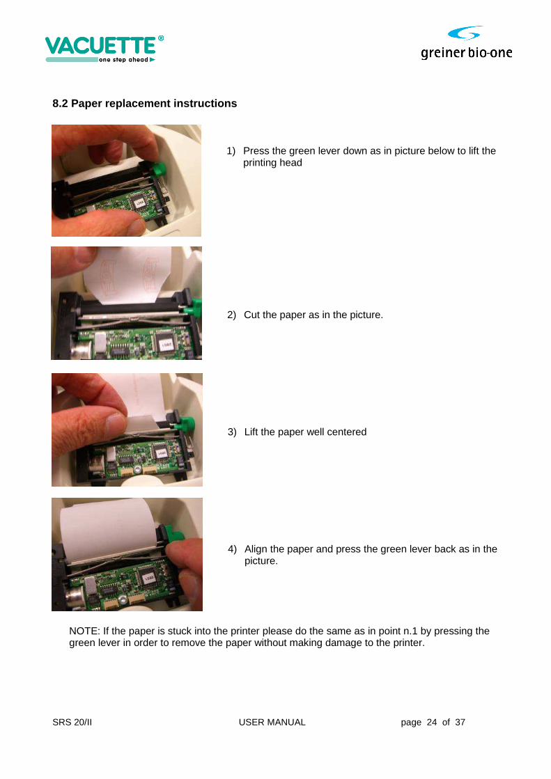
8.2 Paper replacement instructions
1) Press the green lever down as in picture below to lift the printing head
2) Cut the paper as in the picture.
3) Lift the paper well centered
4) Align the paper and press the green lever back as in the picture.
NOTE: If the paper is stuck into the printer please do the same as in point n.1 by pressing the green lever in order to remove the paper without making damage to the printer.
SRS 20/II USER MANUAL page 25 of 37
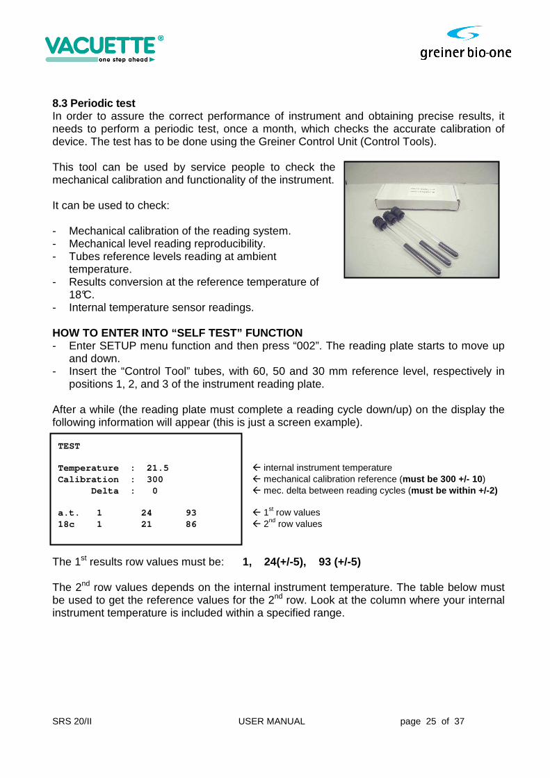
8.3 Periodic test In order to assure the correct performance of instrument and obtaining precise results, it needs to perform a periodic test, once a month, which checks the accurate calibration of device. The test has to be done using the Greiner Control Unit (Control Tools). This tool can be used by service people to check the mechanical calibration and functionality of the instrument. It can be used to check: - Mechanical calibration of the reading system. - Mechanical level reading reproducibility. - Tubes reference levels reading at ambient
temperature. - Results conversion at the reference temperature of
18°C. - Internal temperature sensor readings.
HOW TO ENTER INTO “SELF TEST” FUNCTION - Enter SETUP menu function and then press “002”. The reading plate starts to move up
and down. - Insert the “Control Tool” tubes, with 60, 50 and 30 mm reference level, respectively in
positions 1, 2, and 3 of the instrument reading plate. After a while (the reading plate must complete a reading cycle down/up) on the display the following information will appear (this is just a screen example). TEST Temperature : 21.5 � internal instrument temperature Calibration : 300 � mechanical calibration reference (must be 300 +/- 10 ) Delta : 0 � mec. delta between reading cycles (must be within +/-2) a.t. 1 24 93 � 1st row values 18c 1 21 86 � 2nd row values
The 1st results row values must be: 1, 24(+/-5), 93 (+/-5) The 2nd row values depends on the internal instrument temperature. The table below must be used to get the reference values for the 2nd row. Look at the column where your internal instrument temperature is included within a specified range.
SRS 20/II USER MANUAL page 26 of 37
Temperature correction table for 2 nd row values (°C). Reference
Values Temp.
<= 16.3° Temp.
16.4–18.7 Temp.
18.8–21.2 Temp.
21.3–23.7 Temp.
23.8–26.2 Temp.
26.3–28.7 Temp.
28.8–31.2 Temp. > 31.3
24 27 24 23 21 19 17 15 15
93 103 96 91 86 81 75 70 70
9. TROUBLESHOOTING GUIDE Before calling for a service technician, please check the handling of sample collection, mixing procedures and operating instructions
ALARM CAUSE REMEDY lev a) sample level high or low
b) the label was not placed in its proper position. Refer to page 23.
a)repeat sample collection b)replace label and repeat analysis
rem sample has been removed re-insert sample Thermometer error “Temperature error”
sensor malfunction data-analysis is not converted to 18 C. Call service assistance
System stopped motor or mechanical defect Call service assistance Data result is not printed verify in set-up menu (6) if
printer (I) is enabled.
a) Check power supply b) Check cable c) Replace printer
Data result is not credible a) sample clot b) sample has foam c) sample measured after 4 hours from sample collection d) have the instructions for sample mixing been used ? e) Did you consider the automatic temp. conversion of the SRS 20/II
a) repeat sample collection b) re-mix gently
CCD Scanner does not read barcode
a) Check cable b) Re- configure scanner (See manual) c)Call service assistance
HOST communication failure a) cable b) SRS 20/II is in main menu? c) There is no data in memory
a) Check cable if it is correct d) call service assistance
Info on display is readable, but background is dark.
Neon lamp display broken call service assistance
Memory error Memory broken call service assistance Keyboard is malfunctioning call service assistance Clock error lithium battery flat or clock IC
broken call service assistance
SRS 20/II USER MANUAL page 27 of 37
NOTE: For validations of test results please refer to: CLSI document H02-A5 Vol. 31 No 11 “Procedure for the Erythrocyte Sedimentation Rate Test” Fifth edition; Approved Standard (National Committee for Clinical Laboratory Standards)

SRS 20/II USER MANUAL page 28 of 37
10. TECHNICAL SPECIFICATION SRS 20/II
Area of application: Blood sedimentation rate analysis Instrument size: Width 360 mm Depth 455 mm Height 190 mm Weight: about 5.5 kg Voltage: external power: 100-240 V AC +/-10%, 0.6 A, 47-63 Hz output: + 5 V DC 0.3 A, + 12 V DC 1.2 A Operating Conditions: temperature 15° - 32° C roo m temperature humidity: 45% - 85% altitude: up to 2.000 m overvoltage: category II pollution: degree 2 for indoor use only sound level 24 dBA Analysis time: 30' or 60' as selected Analytical capacity: max 40 tests/h Reading chamber: 20 Loading capacity: max 20 samples at a time Loading pattern: random Results: in Westergren mm (by interpolation) correlated to ½h or 1h or 2h. Temperature correction: automatic compensation referred to 18°C (Manley) Measuring method: infrared barrier Reading resolution: +/- 0,2 mm Results resolution: +/- 1 mm Blood drawing level acceptance from normal +4 mm / -10 mm Display: Graphic LCD with back-lighting Keyboard: 15 keys Interface: RS 232 bi-directional Printer interface: RS232 serial output CCD scanner interface: TTL serial input Applicable standards ISO 9001:2008, ISO 13485:2003, EN ISO 14971, EN
ISO 18113-3, EN 13612, EMC Directive 2004/108/EC and LV Directive 2006/95/EC and following amendments.
General Directives: 2002/95/EC 2003/108/EC

SRS 20/II USER MANUAL page 29 of 37
EMC Standards: EN 61326-6:2006
Safety Standards: IEC/EN 61010-1:2001 IEC/EN 61010-2-101:2002 IEC/EN 61010-2-051:2003 Machine Directives: 98/79/EC 2006/42/EC Transport and storage: Do not refrigerate during transport Storage temperature : 4 – 30°C Storage relative humidity: 20%-85%

SRS 20/II USER MANUAL page 30 of 37
11. PACKAGING INFORMATION BOX SIZE: 43 x 60 x 30 cm WEIGHT: 9 kg open box instrument protection
ACCESSORIES
dust cover user manual power supply
power cable thermal printer paper self-test tool

SRS 20/II USER MANUAL page 31 of 37
APPENDIX A. THEORETICAL INFORMATION A.1 Westergren Method This is the standard method in accordance with the National Committee for Clinical Laboratory Standards. It consists in a support that keeps the Westergren tubes, containing non-clottable blood perfectly vertical and hermetically sealed. Westergren tubes have a diameter of not less than 2.55 mm and are graduated up to 200 mm. As soon as the sample is taken, it is mixed with a 3.2 % sodium citrate solution, in the ratio of respectively four to one (1.6 ml + 0.4 ml of sodium citrate). The blood thus prepared and well mixed is drawn into a Westergren tube up to the zero mark. The tube is putted in the appropriate support and the erythrocyte level is read after 60 and 120 min. A.2 Variations of ESR A. Net increase of ESR (100 mm or more per hour) 1. Multiple myeloma and 12. Internal hemorrhage Waldenstrom macroglobulinemia 13. Acute hepatitis 2. Malignant lymphoma 14. Ectopic pregnancy 3. Leukemia unbroken after the third month 4. Serious anemia 15. Broken ectopic pregnancy 5. Carcinomas 16. Menstruation 6. Sarcomas 17. Normal pregnancy after the 7. Serious bacterial infections third month 8. Collagenosis 18. Oral contraceptives taken 9. Biliary or portal cirrhosis 19. Tuberculosis 10. Ulcerous colitis 20. Postcommissurotomy syndrome 11. Serious nephrosis 21. Dextran administered intravenously

SRS 20/II USER MANUAL page 32 of 37
B. Moderate increase of ESR C. Normality of ESR ( most cases) 1. Acute and chronic contagious diseases 1. First stage acute appendicitis 2. Acute localized infections (in the first 24 hours) 3. Reactivation of a chronic infection 2. Precocious integral ectopic pregnancy 4. Rheumatic illness 3. Malarial paroxysm 5. Rheumatoid arthritis 4. Cirrhosis of the liver 6. Myocardial infarction 5. Arthrosis 6. Mononucleosis 7. Acute allergies 7. Malignant tumor with necrosis 8. Virosis without complications 8. Hyperthyroidism 9. Peptic ulcer 9. Hypothyroidism 10.Typhoid fever 10. Lead or arsenic poisoning 11.Undulant fever 11. Nephrosis 12. Rheumatic carditis with cardiac decompensation 13. Whooping cough _______________________________________________________________________ 1) THYGESEN, J.E.(1942). The mechanism of blood sedimentation. Acta Medica Scandinavica, Suppl. 134. 2) WINTROBE,M.M. and Landsberg, J.W. (1935). A standardized technique for the blood sedimentation test. American Journal of Medical Sciences, 189, 102 3) HARDWICKE, J. and SQUIRE, J.R. (1965). The basis of the erythrocyte sedimentation rate. Clinical Science, 11, 333 4) International Committee for Standardization in Hematology (1977). Recommendation for measurement of erythrocyte sedimentation rate of human blood. American Journal of Clinical Pathology, 68,505 5) LASCARI, A.D. (1972). The erythrocyte sedimentation rate. Pediatric Clinics of North America, 19,1113 6) MANLEY, R.W. (1957). The effect of room temperature on erythrocyte sedimentation rate and its corrections. Journal of Clinical Pathology, 10, 354 7) CLSI Document H02-A5, vol. 31 N°11 “ Procedure for the Erythrocyte Sedimentation Rate Test”.
SRS 20/II USER MANUAL page 33 of 37
B. PRINTER TYPES PROTOCOL DESCRIPTION
The printer setup can be changed to 5 different modes:
NO - Printer output is disabled;
I - Internal printer APS CP205MRS;
1 - for CUSTOM ENGENEERING DP24 and DPT282 printers (custom
protocol);
2 - ESC/POS Graphic protocol type 1;
3 - ESC/POS Graphic protocol type 2;
The ESC/POS type 1 protocol use the following control codes:
ESC "1" 0 to set min line space (1/8")
ESC * 0 nn dt to print graphic line
ESC "1" 32 to set normal line space (1/6")
The ESC/POS type 2 protocol use the following control codes:
ESC "0" 0 to set min line space (1/8")
ESC * 0 nn dt to print graphic line
ESC "2" 0 to set normal line space (1/6")
SRS 20/II USER MANUAL page 34 of 37
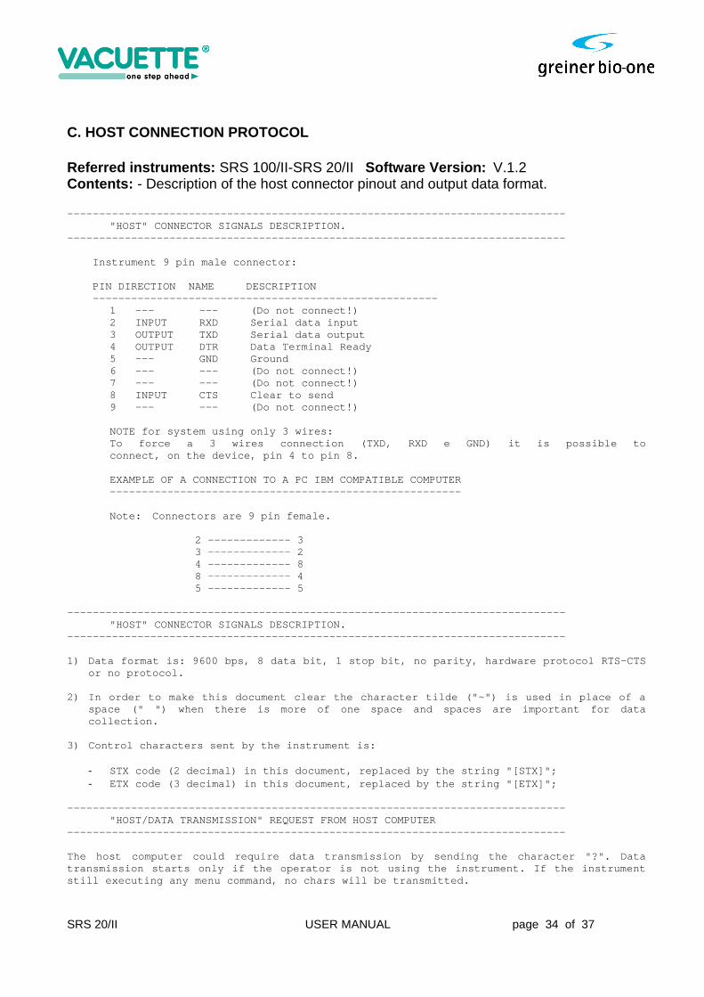
C. HOST CONNECTION PROTOCOL Referred instruments: SRS 100/II-SRS 20/II Software Version: V.1.2 Contents: - Description of the host connector pinout and output data format. --------------------------------------------------- --------------------------- "HOST" CONNECTOR SIGNALS DESCRIPTION. --------------------------------------------------- --------------------------- Instrument 9 pin male connector: PIN DIRECTION NAME DESCRIPTION ----------------------------------------------- ------- 1 --- --- (Do not connect!) 2 INPUT RXD Serial data input 3 OUTPUT TXD Serial data output 4 OUTPUT DTR Data Terminal Ready 5 --- GND Ground 6 --- --- (Do not connect!) 7 --- --- (Do not connect!) 8 INPUT CTS Clear to send 9 --- --- (Do not connect!) NOTE for system using only 3 wires: To force a 3 wires connection (TXD, RXD e GND) it is p ossible to connect, on the device, pin 4 to pin 8. EXAMPLE OF A CONNECTION TO A PC IBM COMPATIBLE COM PUTER -------------------------------------------------- ----- Note: Connectors are 9 pin female. 2 ------------- 3 3 ------------- 2 4 ------------- 8 8 ------------- 4 5 ------------- 5 --------------------------------------------------- --------------------------- "HOST" CONNECTOR SIGNALS DESCRIPTION. --------------------------------------------------- --------------------------- 1) Data format is: 9600 bps, 8 data bit, 1 stop bit, n o parity, hardware protocol RTS-CTS
or no protocol. 2) In order to make this document clear the character tilde ("~") is used in place of a
space (" ") when there is more of one space and spa ces are important for data collection.
3) Control characters sent by the instrument is:
- STX code (2 decimal) in this document, replaced by the string "[STX]"; - ETX code (3 decimal) in this document, replaced by the string "[ETX]";
--------------------------------------------------- --------------------------- "HOST/DATA TRANSMISSION" REQUEST FROM HOST COMPUTER --------------------------------------------------- --------------------------- The host computer could require data transmission b y sending the character "?". Data transmission starts only if the operator is not usi ng the instrument. If the instrument still executing any menu command, no chars will be transmitted.
SRS 20/II USER MANUAL page 35 of 37
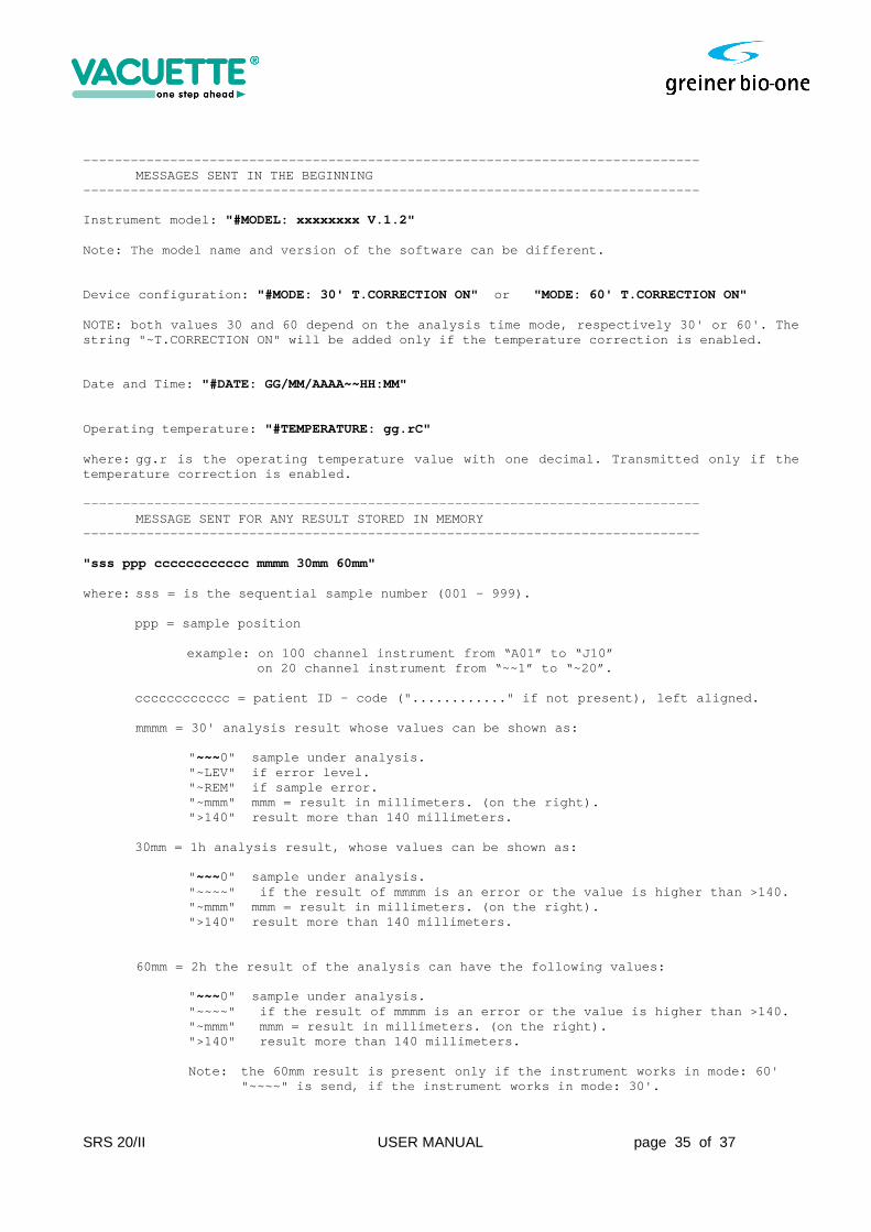
--------------------------------------------------- --------------------------- MESSAGES SENT IN THE BEGINNING --------------------------------------------------- --------------------------- Instrument model: "#MODEL: xxxxxxxx V.1.2" Note: The model name and version of the software ca n be different. Device configuration: "#MODE: 30' T.CORRECTION ON" or "MODE: 60' T.CORRECTION ON" NOTE: both values 30 and 60 depend on the analysis time mode, respectively 30' or 60'. The string "~T.CORRECTION ON" will be added only if the temperature correction is enabled. Date and Time: "#DATE: GG/MM/AAAA~~HH:MM" Operating temperature: "#TEMPERATURE: gg.rC" where: gg.r is the operating temperature value with one decimal. Transmitted only if the temperature correction is enabled. --------------------------------------------------- --------------------------- MESSAGE SENT FOR ANY RESULT STORED IN MEMORY --------------------------------------------------- --------------------------- "sss ppp cccccccccccc mmmm 30mm 60mm" where: sss = is the sequential sample number (001 - 999).
ppp = sample position example: on 100 channel instrument from “A01” to “J 10”
on 20 channel instrument from “~~1” to “~20”.
cccccccccccc = patient ID - code ("............" if not present), left aligned.
mmmm = 30' analysis result whose values can be show n as:
" ~~~0" sample under analysis. "~LEV" if error level. "~REM" if sample error. "~mmm" mmm = result in millimeters. (on the right) . ">140" result more than 140 millimeters.
30mm = 1h analysis result, whose values can be show n as:
" ~~~0" sample under analysis. "~~~~" if the result of mmmm is an error or the v alue is higher than >140. "~mmm" mmm = result in millimeters. (on the right) . ">140" result more than 140 millimeters.
60mm = 2h the result of the analysis can have the f ollowing values:
" ~~~0" sample under analysis. "~~~~" if the result of mmmm is an error or the v alue is higher than >140. "~mmm" mmm = result in millimeters. (on the right ). ">140" result more than 140 millimeters. Note: the 60mm result is present only if the instr ument works in mode: 60'
"~~~~" is send, if the instrument works in mode: 30 '.
SRS 20/II USER MANUAL page 36 of 37
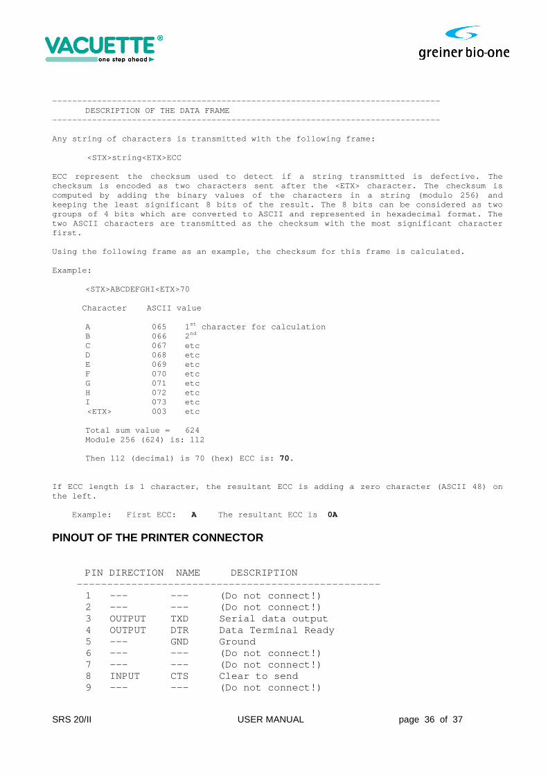
--------------------------------------------------- --------------------------- DESCRIPTION OF THE DATA FRAME --------------------------------------------------- --------------------------- Any string of characters is transmitted with the fo llowing frame: <STX>string<ETX>ECC ECC represent the checksum used to detect if a stri ng transmitted is defective. The checksum is encoded as two characters sent after th e <ETX> character. The checksum is computed by adding the binary values of the charact ers in a string (modulo 256) and keeping the least significant 8 bits of the result. The 8 bits can be considered as two groups of 4 bits which are converted to ASCII and r epresented in hexadecimal format. The two ASCII characters are transmitted as the checksu m with the most significant character first. Using the following frame as an example, the checks um for this frame is calculated. Example: <STX>ABCDEFGHI<ETX>70 Character ASCII value A 065 1 st character for calculation
B 066 2 nd C 067 etc D 068 etc
E 069 etc F 070 etc G 071 etc H 072 etc I 073 etc <ETX> 003 etc
Total sum value = 624 Module 256 (624) is: 112
Then 112 (decimal) is 70 (hex) ECC is: 70.
If ECC length is 1 character, the resultant ECC is adding a zero character (ASCII 48) on the left. Example: First ECC: A The resultant ECC is 0A
PINOUT OF THE PRINTER CONNECTOR
PIN DIRECTION NAME DESCRIPTION
----------------------------------------------- --- 1 --- --- (Do not connect!) 2 --- --- (Do not connect!) 3 OUTPUT TXD Serial data output 4 OUTPUT DTR Data Terminal Ready 5 --- GND Ground 6 --- --- (Do not connect!) 7 --- --- (Do not connect!) 8 INPUT CTS Clear to send 9 --- --- (Do not connect!)
SRS 20/II USER MANUAL page 37 of 37
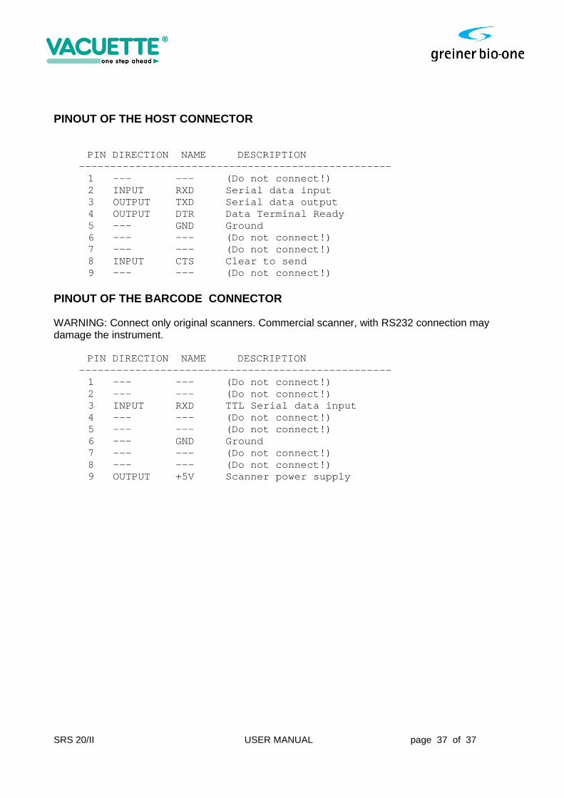
PINOUT OF THE HOST CONNECTOR
PIN DIRECTION NAME DESCRIPTION ----------------------------------------------- --- 1 --- --- (Do not connect!) 2 INPUT RXD Serial data input 3 OUTPUT TXD Serial data output 4 OUTPUT DTR Data Terminal Ready 5 --- GND Ground 6 --- --- (Do not connect!) 7 --- --- (Do not connect!) 8 INPUT CTS Clear to send 9 --- --- (Do not connect!) PINOUT OF THE BARCODE CONNECTOR WARNING: Connect only original scanners. Commercial scanner, with RS232 connection may damage the instrument.
PIN DIRECTION NAME DESCRIPTION ----------------------------------------------- --- 1 --- --- (Do not connect!) 2 --- --- (Do not connect!) 3 INPUT RXD TTL Serial data input 4 --- --- (Do not connect!) 5 --- --- (Do not connect!) 6 --- GND Ground 7 --- --- (Do not connect!) 8 --- --- (Do not connect!) 9 OUTPUT +5V Scanner power supply