Embed Size (px)
Citation preview

U.S. Department of the Interior Bureau of Reclamation Technical Service Center Denver, Colorado September 2011
Report DSO-11-06
Seismic Induced Loads on Spillway Gates Phase I – Literature Review Dam Safety Technology Development Program

REPORT DOCUMENTATION PAGE Form Approved OMB No. 0704-0188
The public reporting burden for this collection of information is estimated to average 1 hour per response, including the time for review ing instructions, searching existing data sources, gathering and maintaining the data needed, and completing and review ing the collection of information. Send comments regarding this burden estimate or any other aspect of this collection of information, including suggestions for reducing the burden, to Department of Defense, Washington Headquarters Services, Directorate for Information Operations and Reports (0704-0188), 1215 Jefferson Davis Highway, Suite 1204, Arlington, VA 22202-4302. Respondents should be aware that notw ithstanding any other provision of law , no person shall be subject to any penalty for failing to comply w ith a collection of information if it does not display a currently valid OMB control number. PLEASE DO NOT RETURN YOUR FORM TO THE ABOVE ADDRESS. 1. REPORT DATE (DD-MM-YYYY) 09-2011
2. REPORT TYPE
3. DATES COVERED (From - To)
4. TITLE AND SUBTITLE Seismic Induced Loads on Spillway Gates Phase I – Literature Review
5a. CONTRACT NUMBER 5b. GRANT NUMBER 5c. PROGRAM ELEMENT NUMBER
6. AUTHOR(S) Jerzy W. Salamon
5d. PROJECT NUMBER 5e. TASK NUMBER 5f. WORK UNIT NUMBER
7. PERFORMING ORGANIZATION NAME(S) AND ADDRESS(ES) Bureau of Reclamation Technical Service Center Structural Analysis Group (86-68110 Denver, Colorado
8. PERFORMING ORGANIZATION REPORT NUMBER DSO-11-06
9. SPONSORING/MONITORING AGENCY NAME(S) AND ADDRESS(ES) Bureau of Reclamation Dam Safety Office Denver, Colorado
10. SPONSOR/MONITOR'S ACRONYM(S) 11. SPONSOR/MONITOR'S REPORT NUMBER(S) DSO-11-06
12. DISTRIBUTION/AVAILABILITY STATEMENT National Technical Information Service, 5285 Port Royal Road, Springfield, VA 22161 13. SUPPLEMENTARY NOTES 14. ABSTRACT This report includes a literature review and compilation of technical references regarding seismic induced loads on spillway gates. The literature review included widely-accepted analytical methods as well as studies focused on the dam-reservoir and spillway gates-reservoir interaction. One of the primary objectives of the literature review was to identify the factors and limitations that are important in determination of hydrodynamic loads on the spillway gates during an earthquake. 15. SUBJECT TERMS Spillway gates, seismic loads, 16. SECURITY CLASSIFICATION OF: 17. LIMITATION
OF ABSTRACT SAR
18. NUMBER OF PAGES 35
19a. NAME OF RESPONSIBLE PERSON
a. REPORT U
b. ABSTRACT U
a. THIS PAGE U
19b. TELEPHONE NUMBER (Include area code)
Standard Form 298 (Rev. 8/98) Prescribed by ANSI Std. Z39.18
Report DSO-11-06 Seismic Induced Loads on Spillway Gates Phase I – Literature Review Technical Service Center
REVISIONS
Date
Description
Pre
pare
d
Che
cked
Tech
nica
l A
ppro
val
P
eer
Rev
iew

Mission Statements The mission of the Department of the Interior is to protect and provide access to our Nation’s natural and cultural heritage and honor our trust responsibilities to Indian Tribes and our commitments to island communities. The mission of the Bureau of Reclamation is to manage, develop, and protect water and related resources in an environmentally and economically sound manner in the interest of the American public.
Table of Contents Introduction ............................................................................................................ 1
Project Background and Objective .................................................................... 1 Spillway Gates - General ................................................................................... 2
Literature Review................................................................................................... 3 Hydrodynamic Pressure on Dams (chronological order) ................................... 3 Hydrodynamic Pressure on Spillway Gates ....................................................... 4
Dam- Reservoir Interaction.................................................................................... 5 Westergaard– “Added Mass Formula” .............................................................. 5 Momentum Balance Method for Sloped Dam by Chwang & Housner ............. 7 Potential Flow Theory for Sloped Dam Face by Chwang ................................. 8 Velocity Potential Solution of Added Mass by Housner ................................... 9 Finite Element Analysis ................................................................................... 11 Laboratory Tests .............................................................................................. 14
Hydrodynamic loads on Spillway Gates .............................................................. 15 Seismic Analysis of Spillway Gates ................................................................ 15 Reclamation’s Practice..................................................................................... 15
Summary of Phase I ............................................................................................. 16 Planning Phase II - Plan for Further Research ..................................................... 17 References ............................................................................................................ 18 Appendix A – Spreadsheet for Hydrodynamic Loads Calculations for Concrete Dams using Westergaard’s Exact and Approximate Formula ............................. 22 Appendix B – Comparison of Hydrodynamic Loads for Concrete Dams per Westergaard’s Theory .......................................................................................... 23

1
Introduction
This Technical Memorandum (TM) documents completion of Phase I of a proposed two-phase research project. Phase I, according to the Project Plan accepted by the Dam Safety Office and funded by the Technology Development Program, consists of a literature review and compilation of technical references regarding seismic induced hydrodynamic loads on spillway gates. The literature review included widely-accepted analytical methods as well as studies focused on the dam-reservoir and spillway gates-reservoir interaction. One of the primary objectives of the literature review was to identify the factors and limitations that are important in determination of hydrodynamic loads on the spillway gates during earthquake. This TM develops a plan for further research in Phase II in subsequent fiscal years.
Project Background and Objective The dynamic reservoir loads developed during an earthquake are of importance in the design and evaluation of the spillway gates. The ground acceleration at the base of a dam during an earthquake can be considerably amplified at the top of the dam. Spillway gates may be subject to this amplified acceleration. This acceleration at the spillway gates could be several times greater than that measured on rock at the abutment, depending on the response of the dam structure, location of the spillway gate, flexibility of the gate structure, actual water head on the gate, and whether the transverse, longitudinal or vertical acceleration is considered. Dynamic stability analyses of spillway gates on dams could be grossly incorrect based on the use of simplified methods for calculations of the hydrodynamic and inertia forces on the dam and the spillway gates. The result could be very costly and potentially unnecessary modifications to existing gates, over-design of new gates, or unreliable risk assessments based on inaccurate analyses of the gates. Standard methods for computing hydrodynamic loads on spillway gates are based on theories developed for concrete dams. In particular, the current practice for computing hydrodynamic loading on dams relies on a method developed by Westergaard for rigid dams [Todd 2002]. The problem arises with the use of the Westergaard simplified formulation for hydrodynamic interaction, pseudo-static methods not accounting for the flexibility of the gates, accurate calculation of the amplification of the ground motion acceleration up through the dam, and the three dimensional effects when the gates are set back from the face of the dam. As the majority of spillway gates are radial gates, the potential failure of the radial gate arms or gate trunnion anchorage during earthquake will result in an uncontrolled release of the reservoir. Equally important is a need for the gates to be operable after a dam has experienced a significant seismic event both to reduce hydrostatic pressure on the potentially damaged and weakened dam structure and to alleviate the consequences should the dam fail at a later time.
2
Queries of the Mechanical Equipment Database indicate that there are over 880 radial spillway gates and approximately 180 fixed wheel spillway gates in Reclamation’s inventory, most being in high seismic regions. New large radial gates are proposed for the following Reclamation’s projects:
• Shasta Dam (dam raise), • Yellowtail Dam, • Buffalo Bill Dam (top seal radial gates), • Folsom JFP for new spillway (currently under construction).
Eight existing radial spillway gates on Folsom Dam are currently in the process of replacement as a result of the risk analysis for the seismic hazard.
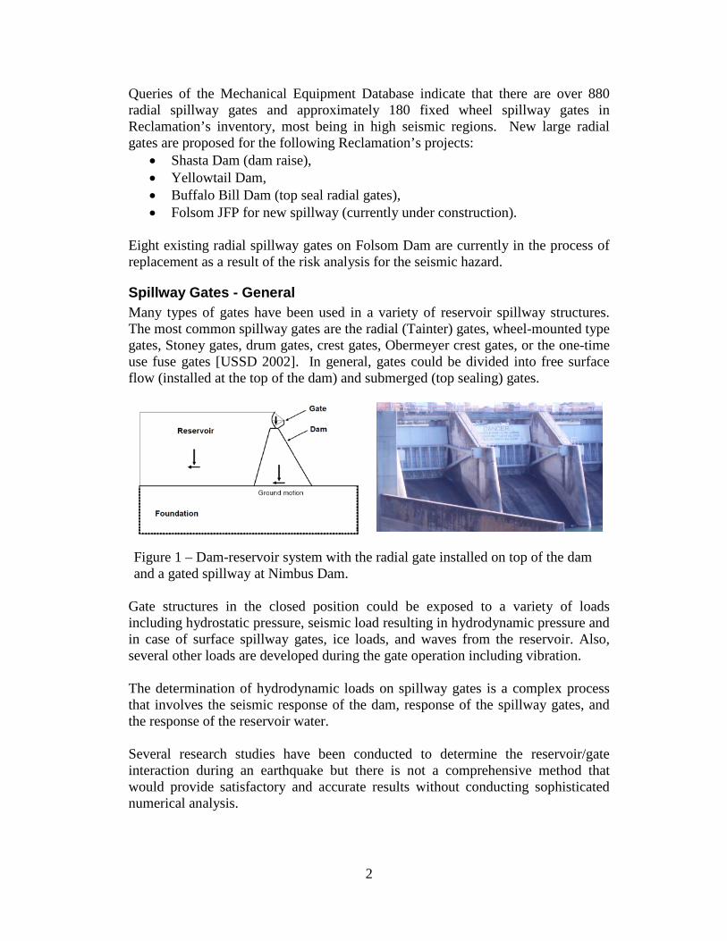
Spillway Gates - General Many types of gates have been used in a variety of reservoir spillway structures. The most common spillway gates are the radial (Tainter) gates, wheel-mounted type gates, Stoney gates, drum gates, crest gates, Obermeyer crest gates, or the one-time use fuse gates [USSD 2002]. In general, gates could be divided into free surface flow (installed at the top of the dam) and submerged (top sealing) gates.
Figure 1 – Dam-reservoir system with the radial gate installed on top of the dam and a gated spillway at Nimbus Dam.
Gate structures in the closed position could be exposed to a variety of loads including hydrostatic pressure, seismic load resulting in hydrodynamic pressure and in case of surface spillway gates, ice loads, and waves from the reservoir. Also, several other loads are developed during the gate operation including vibration. The determination of hydrodynamic loads on spillway gates is a complex process that involves the seismic response of the dam, response of the spillway gates, and the response of the reservoir water. Several research studies have been conducted to determine the reservoir/gate interaction during an earthquake but there is not a comprehensive method that would provide satisfactory and accurate results without conducting sophisticated numerical analysis.
3
Literature Review
Hydrodynamic Pressure on Dams (chronological order) The first systematic hydrodynamic analysis of the dam-reservoir system was performed by H.M. Westergaard, Professor at the University of Illinois in 1931. In the study of the earthquake response of a rigid dam with vertical upstream face, Professor Westergaard derived equations for the hydrodynamic pressure applied to a dam by water in the reservoir as a result of a horizontal harmonic ground/dam motion. The parabolic hydrodynamic pressure distribution over the height of the dam was determined to be the same as a pressure developed by a certain body of water called “added mass” forced to move with the dam during the ground motion. The approximate (simplified) formula of Westergaard for the water pressure on a vertical dam was so fundamental and presented in such simple form that this formula is continuously used by the industry in preliminary dam design and in the seismic evaluation of spillway gates. In a response to the Westergaard’s study, Professor von Karman (1931) from California Institute of Technology obtained distributions of the hydrodynamic pressure on a vertical upstream face of a rigid dam based on a simple “linear momentum-balance” method and the results were very close to the Westergaard’s results (difference estimated by von Karman was about 4 or 5 per cent). The principle of Von Karman’s analysis was that a portion of the fluid attached to the vertical surface of the dam has the full value of the acceleration while the remainder of the water is not affected in the process. For a dam with inclined upstream face with various slopes, Zangar (1952) of Bureau of Reclamation determined the hydrodynamic pressures experimentally using the electric analogy tray experiments. Housner (1954) derived an equation for fluid containers under earthquake loading incorporating a length of the reservoir in the formula. Housner made a distinction between an impulsive pressure that relates to the portion of the fluid that moves in coherence with the structure (the added mass), and the convective pressure that relates to effects like sloshing. Solutions for a rectangular, trapezoidal, segment, and stepped dam were provided as well as for a flexible retaining wall. Chopra (1967) calculated the hydrodynamic pressure on a dam and the dam response under horizontal and vertical ground motions of the earthquake considering the effect of compressibility of the fluid. In 1977 Chwang published results of the exact solution for the equations for the earthquake forces on a rigid dam with an inclined upstream face of constant slope by two-dimensional potential-flow theory. The results obtained from the exact theory are in reasonable agreement with those derived from von Karman’s “momentum-balance method”.
4
Chwang and Housner (1978) in their Momentum Method expanded an analytical solution for the earthquake force on a rigid sloping dam by adopting von Karman’s momentum-balance approach. Pressure wave absorption by sediment at the bottom of the reservoir was studied by Chopra and Fenves (1983) and it was demonstrated that sediment at the bottom of reservoir plays an important role in assessing the real hydrodynamic reservoir pressure on the dam. Lee and Tsai [1991] developed the closed-form solution for the analysis of the dam-reservoir system in time domain. Studies were performed for the dam when the reservoir was both empty and full, considering the interaction between the fluid and the structure. It was demonstrated in the study that reservoir fluid and flexibility of the dam structure itself had greatest impact on interactive forces to both the structure and reservoir. Aviles [1998] gave semi-analytical results for the rigid dam with sloped upstream face with viscous and compressible fluid. Maity (2004) defined an algorithm for the analysis of a coupled elastic dam -reservoir system composed of elastic dam and compressible water. Structural damping of the dam material and radiation damping of the water were incorporated in the equations of motion. The parametric study of the coupled system showed the importance of water height of the reservoir and the material properties of the dam. Several investigations and studies were carried out in the frequency domain using numerical methods, in particular the Finite Element Analysis, along with a system analysis for the wave equation governing the motion of water in reservoir. An extensive study was conducted at the University of California at Berkeley resulting in a computer programs EAGD Chopra (1983) and EADAP Ghanaat (1989) for earthquake analysis of concrete dams. The research performed byAnil Chopra contributed greatly to the understanding of the earthquake response of dam-reservoir system.
Hydrodynamic Pressure on Spillway Gates Anami and Ishii (1988) conducted experimental modal analysis tests for an in-air vibration of the radial gates at Folsom Dam and the theoretical calculations for their vibrations in water flow. As a result of the experimental testing the natural frequency and the corresponding modes were determined. With the aid of the potential theory developed by Rayleigh (1983) and Lamb (1904) for the dissipative-wave radiation problem and the flow fluctuation phenomena (reduced to an initial-boundary value problem), the hydrodynamic pressure on the gate was determined. The results of the analysis suggested a possibility that some of the gate vibration modes will fall into a resonance state.
5
Sasaki, Iwashita and Yamaguchi (2007) studied the basic characteristics of hydrodynamic pressure acting on gates during an earthquake based on numerical analysis that considered the vibration of dam bodies and gates. They proposed a method of calculating hydrodynamic pressure during an earthquake in the seismic performance evaluation analysis of gates. Hydrodynamic loads on the Folsom Dam spillway radial gates were analyzed by Reclamation and the methodology developed, summarized in Reclamation (2001), based on application of a pseudo-static earthquake load determined by combining the effect of the “water added-mass” (reduced for a curved radial gate skinplate) with the earthquake magnification factor. Versluis (2010) performed an extensive study on the hydrodynamic loads on large lock gates at the Technical University in Delft. This research was related with the design of the 55 meters wide and 32 meters high rolling gates for the new Panama Canal locks. The Westergaard and Housner methods were studied and it was concluded that the Housner formula for calculating hydrodynamic loads on the gates deserves priority in a limited length reservoir. In the research a contribution of sloshing effects on the gates was also investigated and it was determined that such dynamic loads can be neglected for the 470 meter long lock.
Dam- Reservoir Interaction
Westergaard– “Added Mass Formula” The study on the hydrodynamic load on dams was led by Professor Westergaard in Denver, Colorado, at the Bureau of Reclamation, in connection with the design of the Hoover Dam and the results of this study were published in ASCE Transactions by Westergaard (1933).
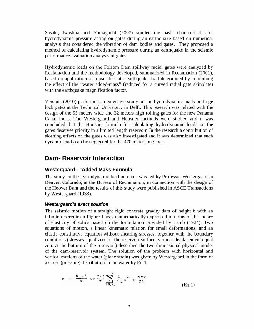
Westergaard’s exact solution The seismic motion of a straight rigid concrete gravity dam of height h with an infinite reservoir on Figure 1 was mathematically expressed in terms of the theory of elasticity of solids based on the formulation provided by Lamb (1924). Two equations of motion, a linear kinematic relation for small deformations, and an elastic constitutive equation without shearing stresses, together with the boundary conditions (stresses equal zero on the reservoir surface, vertical displacement equal zero at the bottom of the reservoir) described the two-dimensional physical model of the dam-reservoir system. The solution of the problem with horizontal and vertical motions of the water (plane strain) was given by Westergaard in the form of a stress (pressure) distribution in the water by Eq.1.
(Eq.1)
6
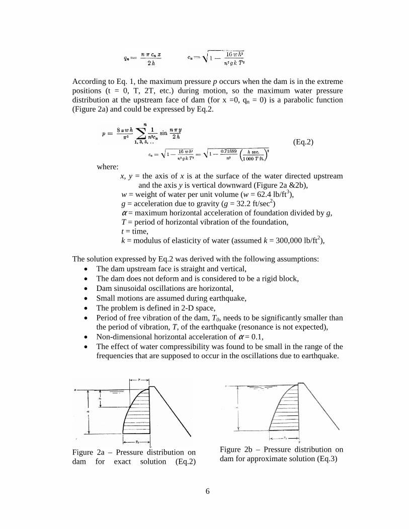
According to Eq. 1, the maximum pressure p occurs when the dam is in the extreme positions (t = 0, T, 2T, etc.) during motion, so the maximum water pressure distribution at the upstream face of dam (for x =0, qn = 0) is a parabolic function (Figure 2a) and could be expressed by Eq.2.
(Eq.2)
where:
x, y = the axis of x is at the surface of the water directed upstream and the axis y is vertical downward (Figure 2a &2b),
w = weight of water per unit volume (w = 62.4 lb/ft3), g = acceleration due to gravity (g = 32.2 ft/sec2) α = maximum horizontal acceleration of foundation divided by g, T = period of horizontal vibration of the foundation, t = time, k = modulus of elasticity of water (assumed k = 300,000 lb/ft2),
The solution expressed by Eq.2 was derived with the following assumptions: • The dam upstream face is straight and vertical, • The dam does not deform and is considered to be a rigid block, • Dam sinusoidal oscillations are horizontal, • Small motions are assumed during earthquake, • The problem is defined in 2-D space, • Period of free vibration of the dam, T0, needs to be significantly smaller than
the period of vibration, T, of the earthquake (resonance is not expected), • Non-dimensional horizontal acceleration of α = 0.1, • The effect of water compressibility was found to be small in the range of the
frequencies that are supposed to occur in the oscillations due to earthquake.
Figure 2a – Pressure distribution on dam for exact solution (Eq.2)
Figure 2b – Pressure distribution on dam for approximate solution (Eq.3)
7
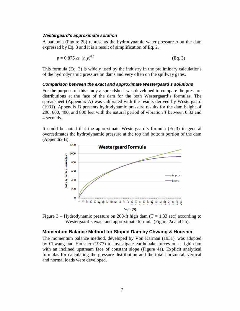
Westergaard’s approximate solution A parabola (Figure 2b) represents the hydrodynamic water pressure p on the dam expressed by Eq. 3 and it is a result of simplification of Eq. 2.
p = 0.875 α (h y)0.5 (Eq. 3)
This formula (Eq. 3) is widely used by the industry in the preliminary calculations of the hydrodynamic pressure on dams and very often on the spillway gates.
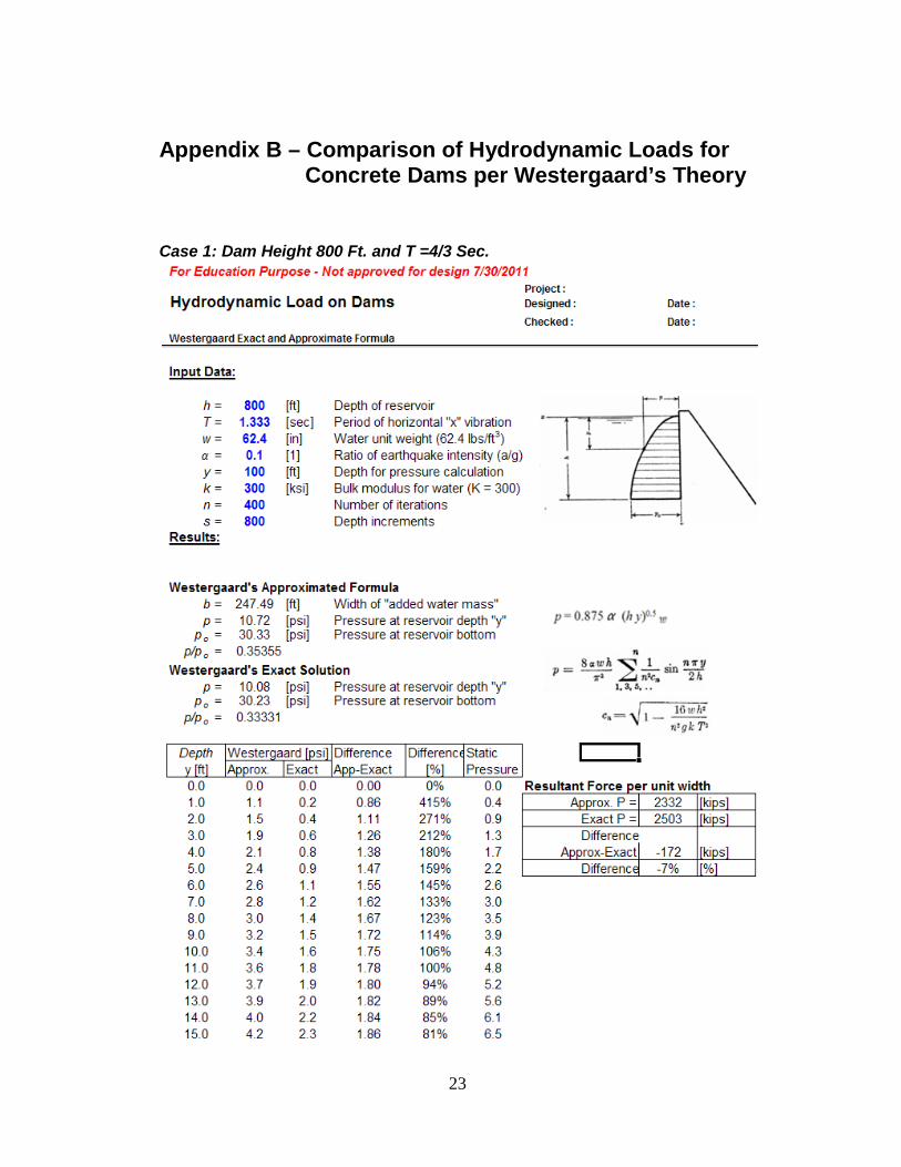
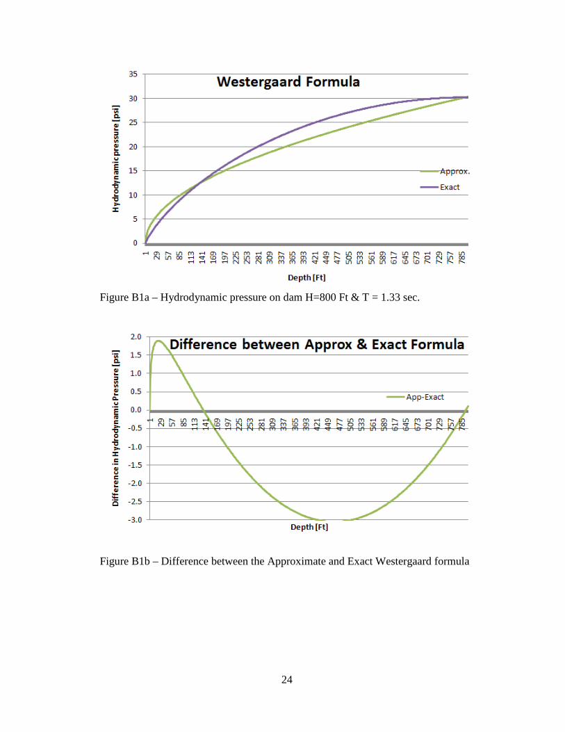
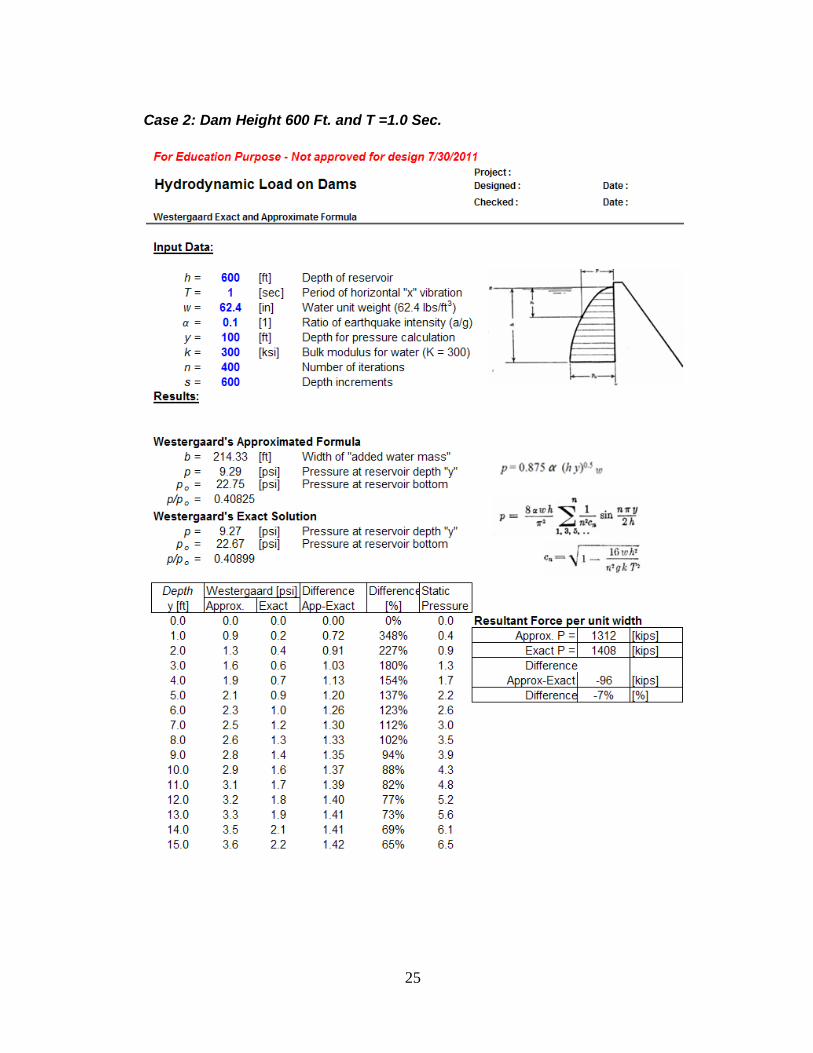
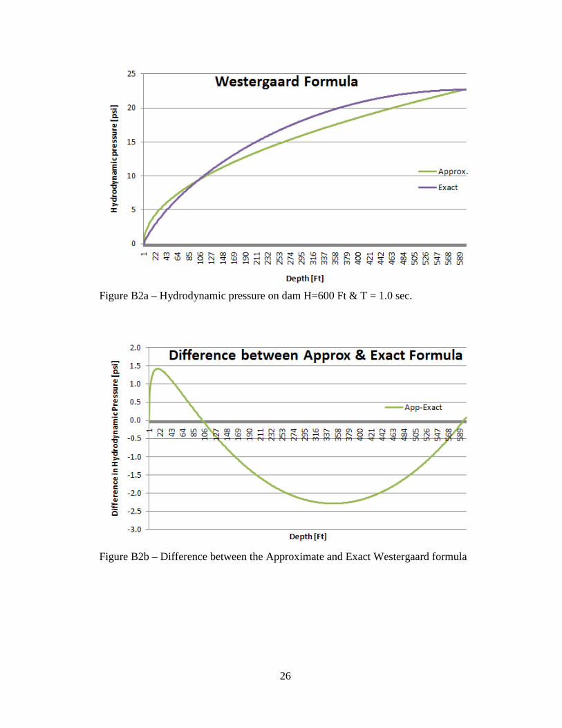
Comparison between the exact and approximate Westergaard’s solutions For the purpose of this study a spreadsheet was developed to compare the pressure distributions at the face of the dam for the both Westergaard’s formulas. The spreadsheet (Appendix A) was calibrated with the results derived by Westergaard (1931). Appendix B presents hydrodynamic pressure results for the dam height of 200, 600, 400, and 800 feet with the natural period of vibration T between 0.33 and 4 seconds. It could be noted that the approximate Westergaard’s formula (Eq.3) in general overestimates the hydrodynamic pressure at the top and bottom portion of the dam (Appendix B).
Figure 3 – Hydrodynamic pressure on 200-ft high dam (T = 1.33 sec) according to
Westergaard’s exact and approximate formula (Figure 2a and 2b).
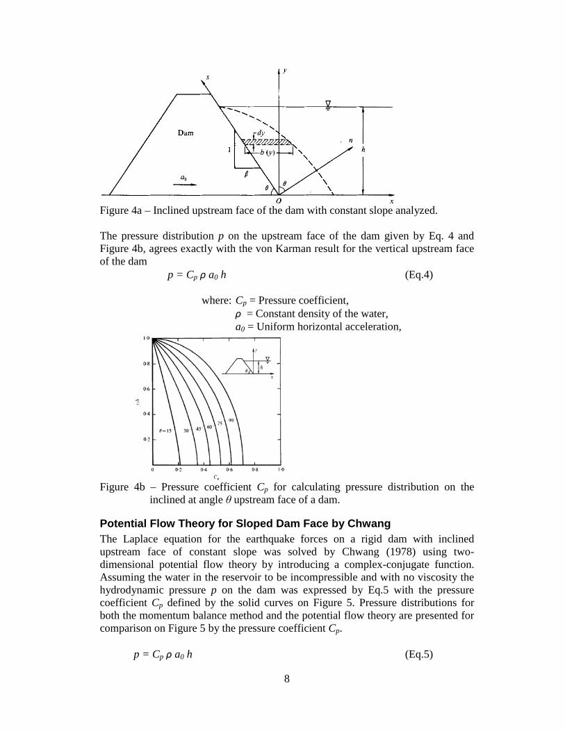
Momentum Balance Method for Sloped Dam by Chwang & Housner The momentum balance method, developed by Von Karman (1931), was adopted by Chwang and Housner (1977) to investigate earthquake forces on a rigid dam with an inclined upstream face of constant slope (Figure 4a). Explicit analytical formulas for calculating the pressure distribution and the total horizontal, vertical and normal loads were developed.
8
Figure 4a – Inclined upstream face of the dam with constant slope analyzed. The pressure distribution p on the upstream face of the dam given by Eq. 4 and Figure 4b, agrees exactly with the von Karman result for the vertical upstream face of the dam
p = Cp ρ a0 h (Eq.4) where: Cp = Pressure coefficient,
ρ = Constant density of the water, a0 = Uniform horizontal acceleration,
Figure 4b – Pressure coefficient Cp for calculating pressure distribution on the
inclined at angle θ upstream face of a dam.
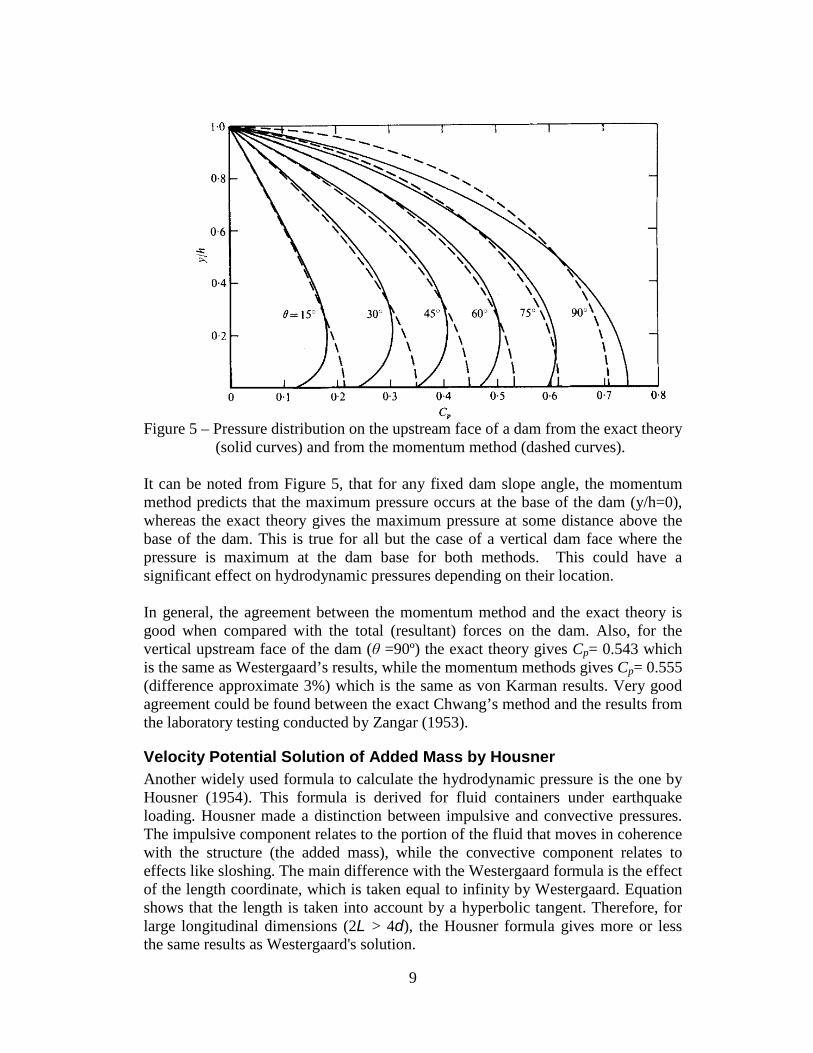
Potential Flow Theory for Sloped Dam Face by Chwang The Laplace equation for the earthquake forces on a rigid dam with inclined upstream face of constant slope was solved by Chwang (1978) using two-dimensional potential flow theory by introducing a complex-conjugate function. Assuming the water in the reservoir to be incompressible and with no viscosity the hydrodynamic pressure p on the dam was expressed by Eq.5 with the pressure coefficient Cp defined by the solid curves on Figure 5. Pressure distributions for both the momentum balance method and the potential flow theory are presented for comparison on Figure 5 by the pressure coefficient Cp.
p = Cp ρ a0 h (Eq.5)
9
Figure 5 – Pressure distribution on the upstream face of a dam from the exact theory
(solid curves) and from the momentum method (dashed curves). It can be noted from Figure 5, that for any fixed dam slope angle, the momentum method predicts that the maximum pressure occurs at the base of the dam (y/h=0), whereas the exact theory gives the maximum pressure at some distance above the base of the dam. This is true for all but the case of a vertical dam face where the pressure is maximum at the dam base for both methods. This could have a significant effect on hydrodynamic pressures depending on their location. In general, the agreement between the momentum method and the exact theory is good when compared with the total (resultant) forces on the dam. Also, for the vertical upstream face of the dam (θ =90º) the exact theory gives Cp= 0.543 which is the same as Westergaard’s results, while the momentum methods gives Cp= 0.555 (difference approximate 3%) which is the same as von Karman results. Very good agreement could be found between the exact Chwang’s method and the results from the laboratory testing conducted by Zangar (1953).
Velocity Potential Solution of Added Mass by Housner Another widely used formula to calculate the hydrodynamic pressure is the one by Housner (1954). This formula is derived for fluid containers under earthquake loading. Housner made a distinction between impulsive and convective pressures. The impulsive component relates to the portion of the fluid that moves in coherence with the structure (the added mass), while the convective component relates to effects like sloshing. The main difference with the Westergaard formula is the effect of the length coordinate, which is taken equal to infinity by Westergaard. Equation shows that the length is taken into account by a hyperbolic tangent. Therefore, for large longitudinal dimensions (2L > 4d), the Housner formula gives more or less the same results as Westergaard's solution.
10
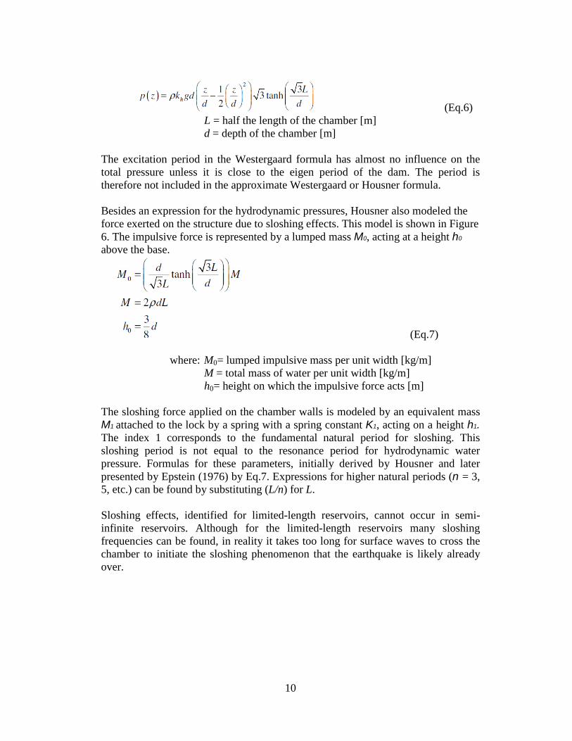
(Eq.6) L = half the length of the chamber [m] d = depth of the chamber [m]
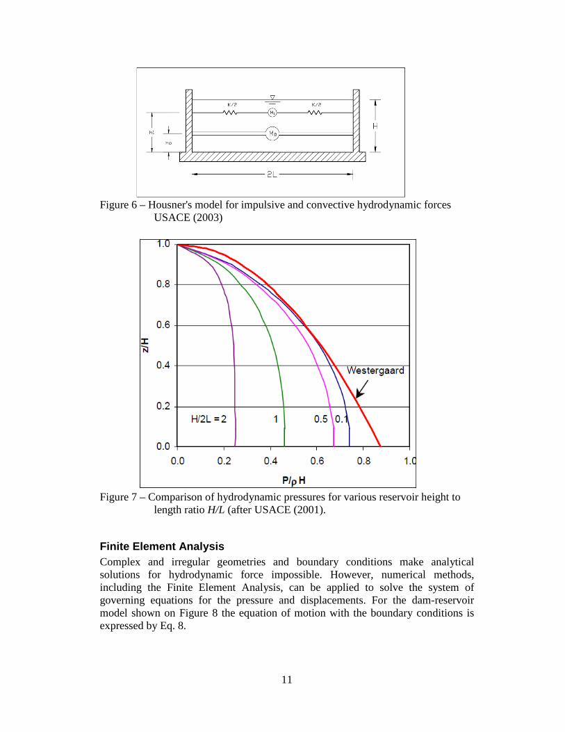
The excitation period in the Westergaard formula has almost no influence on the total pressure unless it is close to the eigen period of the dam. The period is therefore not included in the approximate Westergaard or Housner formula. Besides an expression for the hydrodynamic pressures, Housner also modeled the force exerted on the structure due to sloshing effects. This model is shown in Figure 6. The impulsive force is represented by a lumped mass M0, acting at a height h0
above the base.
(Eq.7) where: M0= lumped impulsive mass per unit width [kg/m]
M = total mass of water per unit width [kg/m] h0= height on which the impulsive force acts [m]
The sloshing force applied on the chamber walls is modeled by an equivalent mass M1 attached to the lock by a spring with a spring constant K1, acting on a height h1. The index 1 corresponds to the fundamental natural period for sloshing. This sloshing period is not equal to the resonance period for hydrodynamic water pressure. Formulas for these parameters, initially derived by Housner and later presented by Epstein (1976) by Eq.7. Expressions for higher natural periods (n = 3, 5, etc.) can be found by substituting (L/n) for L. Sloshing effects, identified for limited-length reservoirs, cannot occur in semi-infinite reservoirs. Although for the limited-length reservoirs many sloshing frequencies can be found, in reality it takes too long for surface waves to cross the chamber to initiate the sloshing phenomenon that the earthquake is likely already over.
11
Figure 6 – Housner's model for impulsive and convective hydrodynamic forces
USACE (2003)
Figure 7 – Comparison of hydrodynamic pressures for various reservoir height to
length ratio H/L (after USACE (2001).
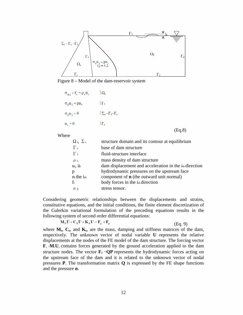
Finite Element Analysis Complex and irregular geometries and boundary conditions make analytical solutions for hydrodynamic force impossible. However, numerical methods, including the Finite Element Analysis, can be applied to solve the system of governing equations for the pressure and displacements. For the dam-reservoir model shown on Figure 8 the equation of motion with the boundary conditions is expressed by Eq. 8.
12
Figure 8 – Model of the dam-reservoir system
(Eq.8) Where
Ωs, Σs structure domain and its contour at equilibrium Γs base of dam structure Γ1 fluid-structure interface ρs mass density of dam structure ui, üi dam displacement and acceleration in the ith direction p hydrodynamic pressures on the upstream face ni the ith component of n (the outward unit normal) fi body forces in the ith direction σij stress tensor.
Considering geometric relationships between the displacements and strains, constitutive equations, and the initial conditions, the finite element discretization of the Galerkin variational formulation of the preceding equations results in the following system of second order differential equations:
(Eq. 9) where Ms, Cs, and Ks, are the mass, damping and stiffness matrices of the dam, respectively. The unknown vector of nodal variable U represents the relative displacements at the nodes of the FE model of the dam structure. The forcing vector Fg =MSUg contains forces generated by the ground acceleration applied to the dam structure nodes. The vector Fp =QP represents the hydrodynamic forces acting on the upstream face of the dam and it is related to the unknown vector of nodal pressures P. The transformation matrix Q is expressed by the FE shape functions and the pressure n.
13
In general, the reservoir model (with compressible water and the hydrodynamic pressure field) needs to satisfy Helmoltz’s wave equation
(Eq. 10) with the boundary condition on Γ4 accounting for the radiation condition. The parameter C is the velocity of sound in water (for the incompressible fluid the wave velocity approaches infinite and Eq. 10 reduces to the Laplace equation). The discrete system of equations is
(Eq. 11)
where MF , CF, and KF are the assembled finite element “mass”, “damping”, and “stiffness” matrices and q is the load vector. The coupled discrete system of equations for the reservoir-dam structure could be expressed by Eq. (12) and can be solved using Finite Element Method. It should be noted that the global “mass” and “stiffness” matrixes of the coupled reservoir-dam system are not symmetric.
Eq. (12)
An analysis of the relative performance of four different fluid-structure finite element models, describing concrete gravity dam-reservoir systems, was studied by Tiliouine and Seghir (1998). Four different scenarios were investigated that includes:
• the rigid dam and incompressible water model (model M1), • flexible dam-incompressible water model (model M2), • rigid dam-compressible water model (model M3), and • flexible dam-compressible water model (model M4).
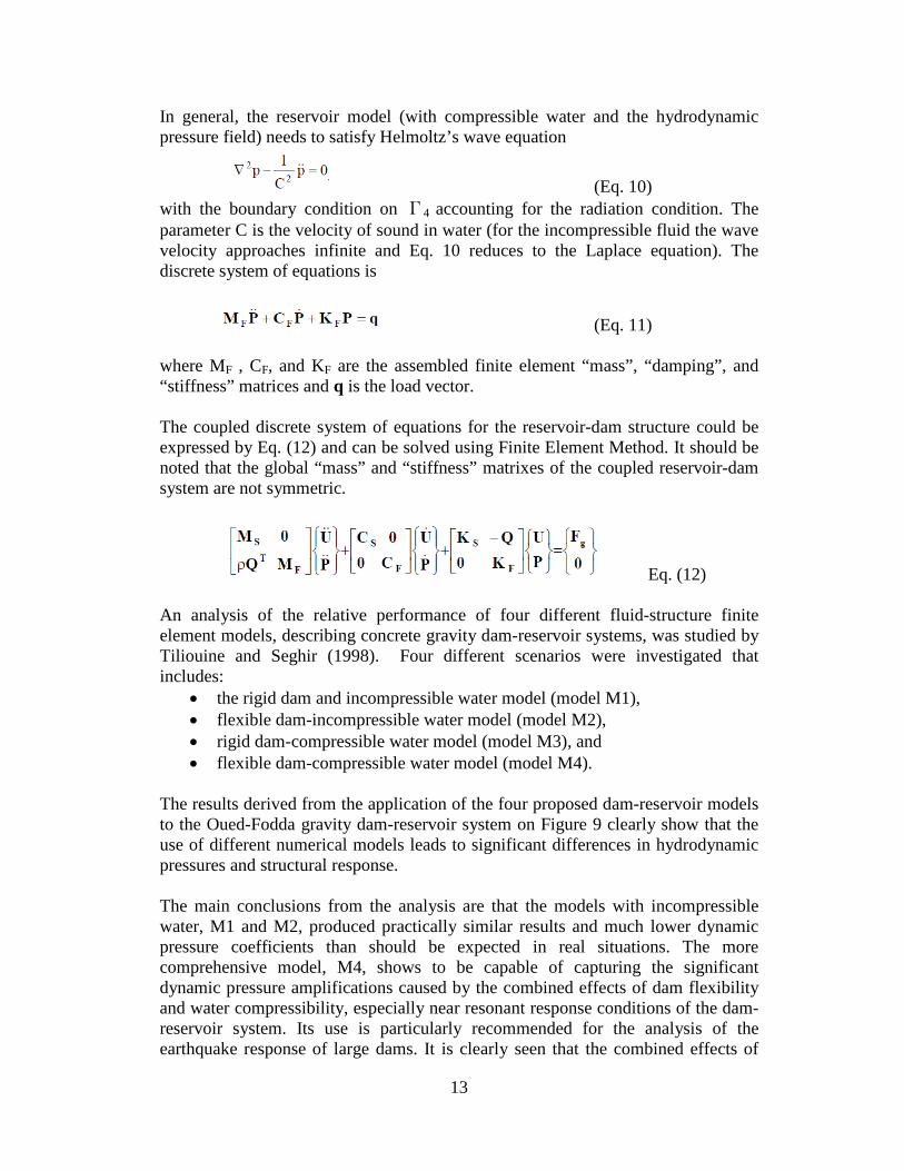
The results derived from the application of the four proposed dam-reservoir models to the Oued-Fodda gravity dam-reservoir system on Figure 9 clearly show that the use of different numerical models leads to significant differences in hydrodynamic pressures and structural response. The main conclusions from the analysis are that the models with incompressible water, M1 and M2, produced practically similar results and much lower dynamic pressure coefficients than should be expected in real situations. The more comprehensive model, M4, shows to be capable of capturing the significant dynamic pressure amplifications caused by the combined effects of dam flexibility and water compressibility, especially near resonant response conditions of the dam-reservoir system. Its use is particularly recommended for the analysis of the earthquake response of large dams. It is clearly seen that the combined effects of
14
dam flexibility and water compressibility are the most critical parameters in studying the response of a dam-reservoir system.
Figure 9 – Pressure coefficient distribution at the face of the dam for four models.
(a) El-Asnam 1980 earthquake, (b) Loma Preita 1989 Earthquake
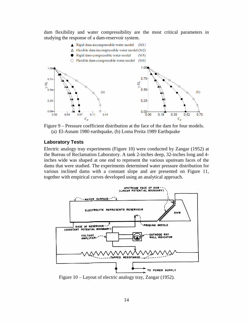
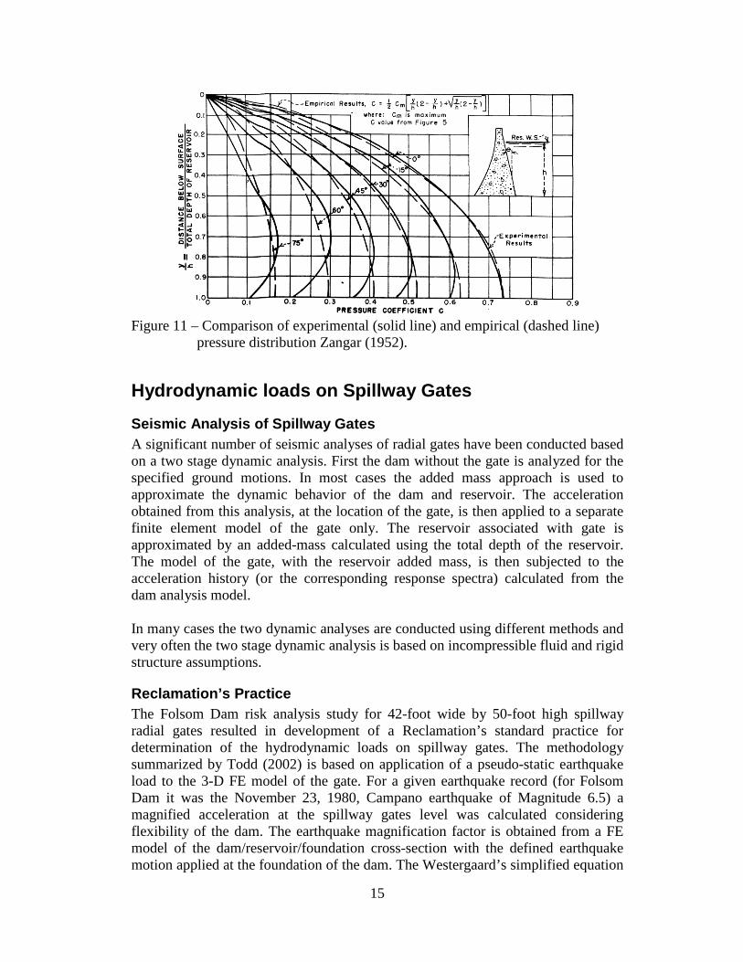
Laboratory Tests Electric analogy tray experiments (Figure 10) were conducted by Zangar (1952) at the Bureau of Reclamation Laboratory. A tank 2-inches deep, 32-inches long and 4-inches wide was shaped at one end to represent the various upstream faces of the dams that were studied. The experiments determined water pressure distribution for various inclined dams with a constant slope and are presented on Figure 11, together with empirical curves developed using an analytical approach.
Figure 10 – Layout of electric analogy tray, Zangar (1952).
15
Figure 11 – Comparison of experimental (solid line) and empirical (dashed line)
pressure distribution Zangar (1952).
Hydrodynamic loads on Spillway Gates
Seismic Analysis of Spillway Gates A significant number of seismic analyses of radial gates have been conducted based on a two stage dynamic analysis. First the dam without the gate is analyzed for the specified ground motions. In most cases the added mass approach is used to approximate the dynamic behavior of the dam and reservoir. The acceleration obtained from this analysis, at the location of the gate, is then applied to a separate finite element model of the gate only. The reservoir associated with gate is approximated by an added-mass calculated using the total depth of the reservoir. The model of the gate, with the reservoir added mass, is then subjected to the acceleration history (or the corresponding response spectra) calculated from the dam analysis model. In many cases the two dynamic analyses are conducted using different methods and very often the two stage dynamic analysis is based on incompressible fluid and rigid structure assumptions.
Reclamation’s Practice The Folsom Dam risk analysis study for 42-foot wide by 50-foot high spillway radial gates resulted in development of a Reclamation’s standard practice for determination of the hydrodynamic loads on spillway gates. The methodology summarized by Todd (2002) is based on application of a pseudo-static earthquake load to the 3-D FE model of the gate. For a given earthquake record (for Folsom Dam it was the November 23, 1980, Campano earthquake of Magnitude 6.5) a magnified acceleration at the spillway gates level was calculated considering flexibility of the dam. The earthquake magnification factor is obtained from a FE model of the dam/reservoir/foundation cross-section with the defined earthquake motion applied at the foundation of the dam. The Westergaard’s simplified equation
16
is used to calculate “added-mass of water”. For the top curved gate skinplate the added mass can be reduced according to Zangar’s pressure curve for an inclined face of the dam. Finally, the pseudo-static pressure on the gate skinplate is determined by combining the effect of the “water added-mass” with the earthquake magnification factor. Advanced FEA techniques are now typical applied to determine the hydrodynamic loads on dams and spillway gates, reflecting current Reclamation practice (implemented most recently in the structural analysis of the gated control structure at Folsom Dam as part of the Joint Federal Project auxiliary spillway in 2010). The reservoir is modeled using solid elements with fluid equation of state and the dam, foundation and gates as an elastic solid structure. The interaction of the reservoir - dam (gate) system is modeled using contact surface elements. The time dependent analysis allows simulation of dam/gate respond to the hydrodynamic load from the reservoir in 3-D space.
Summary of Phase I
The summary of Phase I is as follows: • The primary objective of this report was to list and compare various methods
published in the literature used to determinate hydrodynamic loads on dams and spillway gates generated during earthquake. The report briefly discusses key analytical methods used in the seismic analysis for both the concrete dams and spillway gates.
• Special attention is given in the report to Westergaard’s approach, the most commonly used method used by the industry. Results from exact and simplified Westergaard’s methods are compared. The comparison shows that the simplified Westergaard method significantly overestimates the hydrodynamic load on the top part of the dam (where spillway gates usually are located) when compared with the exact solution. Also significant differences in the hydrodynamic pressure calculated using both methods can be observed at the bottom part of the dam.
• The assumption of a vertical plane upstream face and rigid model of the dam in
the Westergaard formula (used for analysis of the spillway gate) is not valid for radial gates, nor is the spillway gate part of a rigid monolithic structure. The Westergaard formula or any equivalent 2-D model does not represent important 3-D effects of the spillway gates and should be used only in preliminary assessments.
• As part of this task, an Excel spreadsheet was developed. The spreadsheet implements both the exact and approximate Westergaard’s approaches and allows comparison of hydrodynamic loads calculated by both methods. For a
17
gravity dam with a vertical upstream face, calculations using the exact solution could be performed for various parameters including depth of the reservoir, period of horizontal vibration, bulk modulus and unit weight of water, and earthquake acceleration. The spreadsheet, when checked and approved, could be used by Reclamation in the preliminary analysis of gravity dams.
Planning Phase II - Plan for Further Research
In the next phase a parametric study of the spillway gates will be recommended using 3-D finite element software. Various parameters will be analyzed including the response of the dam to seismic loads, the size and type of the spillway gates, and the location of the spillway gate with respect to the face of the dam and to the dam crest. Finite Element analysis results will be compared with the analytical methods (listed above) and the study variations might include:
• Rigid dam and gate with long reservoir to match Westergaard’s model • Flexible dam and stiff gate • Flexible dam and “normal” gate • Gates at the dam face or backset in a channel • Gates at various locations along the dam height
The results of this research will help develop guidelines for the calculations of the hydrodynamic loads on the spillway gates that result from seismic excitation. The guidelines could be adopted by the Dam Safety Office in the design of the new spillway gates as well as in the risk analysis of the existing radial gates in the Reclamation inventory. The 3-D analysis would be appropriate for gates with complex geometry. The future report will provide a better understanding of hydrodynamic loads applied to the spillway gates during earthquake before a multi-million dollar modification to the gate structure is recommended or other dam safety decisions made.
18
References
ASCE (1984), Fluid/Structure Interaction during Seismic Excitation, ASCE Committee on Seismic Analysis of the Committee on Nuclear Structures and Materials of the Structural Division. Anami K., Ishii N. (1988), In-air and in-water natural vibrations of Folsom Dam Radial gate in California, Experimental Mechanics, Balkema, Rotterdam. Anami K., Ishii N. (1988), In-air and in-water natural vibrations of Folsom Dam Radial gate in California, Experimental Mechanics, Balkema, Rotterdam. Aslam M., Wilson E.L., Button M., Ahlgren E., (2002), Earthquake Analysis of Radial Gates/Dam Including Fluid-Structure Interaction, Proceedings, Third US-Japan Workshop on Advanced Research on Earthquake Engineering for Dams, San Diego, CA, June 2002. Bureau of Reclamation (2009), Dam Safety Risk Analysis Best Practices Training Manual, Chapter 23 – Seismic Failure of Spillway/Retaining Walls, Bureau of Reclamation, Denver, Colorado, Version 1.1, May 2009. Bureau of Reclamation (2010), Mechanical Equipment Database, Bureau of Reclamation, Technical Service Center, Denver, 2010. Bureau of Reclamation (2001), Spillway Gate Failure or Misoperation: Representative Case Histories, Bureau of Reclamation, Graham W. J., Hilldale R. C., DSO-01-01, Denver, September 2001. Bureau of Reclamation (2001), Seismic Structural Analysis of the Spillway Gates for Folsom Dam, Bureau of Reclamation, TM No. FD-8110-33-01-02, Denver. Bureau of Reclamation (1952), Hydrodynamic Pressures on Dams due to Horizontal Earthquake Effects, Bureau of Reclamation, Zangar C.N., Engineering Monographs No. 11, Denver. Chopra A. K. (1967), Reservoir-Dam Interaction during Earthquakes, Bulletin of the Seismic Society of America. Chopra A. K., Fenves G. (1983), Effect of Reservoir Bottom Absorption on Earthquake Response of Concrete Gravity Dams, Earthquake Eng. Stru. Dyn., Vol. 11. Chwang A. T., Housner G. (1977), Hydrodynamic Pressures on sloping Dams during Earthquakes, Part 1 – Momentum Methods, J. Fluid Mech. Vol. 87, Part 2, pp. 335-341.
19
Chwang A. T. (1978), Hydrodynamic Pressures on sloping Dams during Earthquakes, Part 2 – Exact theory, J. Fluid Mech. Vol. 87, Part 2, pp. 343-348. Daniell W. E., Taylor C. A. (2000), Seismic Analysis and Dynamic Testing of Spillway Radial Gate, 12 WCEE. Davis C. V., Sorensen K. E. (1984), Handbook of Applied Hydraulics, McGraw Hill Book Co., 3td Ed. Dowdell D. J., Fan B. H. (2004), Practical Aspects of Engineering Seismic Dam Safety – Case Study of a Concrete Gravity Dam, 13 WCEE, Vancouver, Canada. Epstein H. I. (1976), Seismic Design of Liquid-Storage Tanks, Journal of the structures Division, ASCE, Vol. 102, No. ST9, pp 1659-1673. Erbisti P. C. F. (2004), Design of Hydraulic Gates, J. Balkema Publishers. Ghanaat Y., Clough R.W., (1989), EADAP Enhanced Arch Dam Analysis Program, UCB/EERC089/07, University of California at Berkeley. Haroun M.A., Housner G. W. (1990), Seismic Design of Liquid Storage Tanks, Selected Earthquake Engineering papers of G.W. Housner, ASCE. Hall J.F., Chopra A. K. (1980), Dynamic Response of Embankment Concrete- Gravity and Arch Dams Including Hydrodynamic Interaction, UC Berkeley, Report No. USB/EERC-80/39. Housner G. W. (1954), Earthquake Pressure on Fluid Containers, 13 WCEE, California Institute of Technology, Pasadena. Housner G. W. (1990), The Momentum-balance Method in Earthquake Engineering, Selected Earthquake Engineering papers of G.W. Housner, ASCE. Ishii N. (1990), Flow-Induced vibration of Long-Span Gates, JSME International Journal, Series II, Vol. 33, No.4. Jacobsen L.S., Ayre R.S. (1951), Hydrodynamic Experiments with Rigid Cylindrical Tanks Subject to Transient Motions, Bull. Seismic Soc. Amer., Vol. 41. Kolkman P.A. (1979), Development of Vibration-Free Gate Design: Learning from Experience and Theory, Symposium on Practical Experiences with Flow-Induced Vibrations, Karlsruhe, September 3-6, 1979. Kotsubo S. (1959), Dynamic Water Pressures on Dams due to irregular Earthquakes, Memoirs Faculty of Engineering, Kyushu University, Japan, Vol. 18.
20
Kucukarslan S. (2003), Dam-Reservoir Interaction for Incompressible-Unbounded Fluid Domains using an Exact Truncation Boundary Conditions, 16th ASCE Engineering Mechanics Conference, Seattle. Lamb H. (1932), Hydrodynamics, Cambridge. Lee G.C., Tsai C.S. (1991), Time-domain analyses of dam-reservoir system I: Exact solution, Journal of Engineering Mechanics 1990-2006. Lewin J. (2001), Hydraulic Gates and Valves, Thomas Telford Publisher. Lewin J., Ballard G., Bowles D.S. (2003), Spillway Gate Reliability in the context of overall Dam Failure Risk, 2003 USSD Annual Lecture, Charleston SC. Maity D. (2004), Coupled Hydrodynamic Response of Dam-reservoir System, IE (I) Journal. Naudascher E. (1991), Hydrodynamic Forces, IAHR AIRH Hydraulic Structures Design Manual 3, A.A. Balkema, Rotterdam. Okabe S. (1924), General Theory on Earth Pressure and Seismic Stability of Retaining Wall and Dam, Journal of Japan Society of Civil Engineers, Vol.10, No.6, 1924. Porter C.S., Chopra A. K. (1980), Dynamic Response of Simple Arch Dams Including Hydrodynamic Interaction, UC Berkeley, Report No. USB/EERC-80/17. Sasaki T., Iwashita T., Yamaguchi Y. (2007), Calculation Method of Hydrodynamic Pressure in Seismic Response Analysis of Gates, Technical Report on the 39th Joint Meeting May 2007, Panel on Wind and Seismic Effects, Tsukuba, Japan. Stelson T.E., (1957) Virtual Mass and Acceleration in Fluids, ASCE Transactions, Vol. 122, p 518. Todd R.V. (2002), Determining Earthquake Loading on Spillway Gates, Hydro Review, Volume XXI, No.4, pp 92-99. Tiliouine B., Seghir A. (1998), Fluid-structure models for dynamic studies of dam-water system, 11th European Conference on Earthquake Engineering, Balkema, Rotterdam, ISBN 90 5410 982 3 . USACE (1999), U.S. Army Corp of Engineers, EM 1110-2-6050 – Response Spectra and Seismic Analysis for Concrete Hydraulic Structures, June 1999.
21
USACE (2000), U.S. Army Corp of Engineers, EM 1110-2-2702 – Design of Spillway Tainter Gates, January 2000. USACE (2003), U.S. Army Corp of Engineers, EM 1110-2-6051 – Time-History Dynamic Analysis of Concrete Hydraulic Structures, December 2003. USACE (2005), U.S. Army Corp of Engineers, ERDC/GSL TR-05-22 – Dynamic Testing and Numerical Correlation Studies for Folsom Dam, September 2005. USACE (2007), U.S. Army Corp of Engineers, EM 1110-2-6053 – Earthquake Design and Evaluation of Concrete Hydraulic Structures, May 2007. USSD (2002), Improving Reliability of Spillway Gates, December 2002. Von Karman T. (1931), Discussion of Hydrodynamic Pressures on Dams due to Horizontal Earthquake Effects by H. M. Westergaard Transactions, ASCE Transactions, pp. 434-472. Versluis M. (2010), Hydrodynamic Pressures on Large Lock Structures, Master Thesis, TU Delft, April 2010. Westergaard H. M. (1931), Water Pressures on Dams during Earthquakes, ASCE Transactions, pp. 418-433, November 1931. Wickert G., Schmausser G. (1971), Stahlwasserbau, Theorie, Konstruktive Losungen, Specielle Probleme, Springer Verlag. Zanger C. N., (1952), Hydrodynamic pressures on Dams due to horizontal Earthquake Effects, Bureau of Reclamation, Engineering Monograph No.11. Zienkiewicz O. C., (1964), Hydrodynamic pressures due to Earthquakes, Water Power.
22
Appendix A – Spreadsheet for Hydrodynamic Loads Calculations for Concrete Dams using Westergaard’s Exact and Approximate Formula
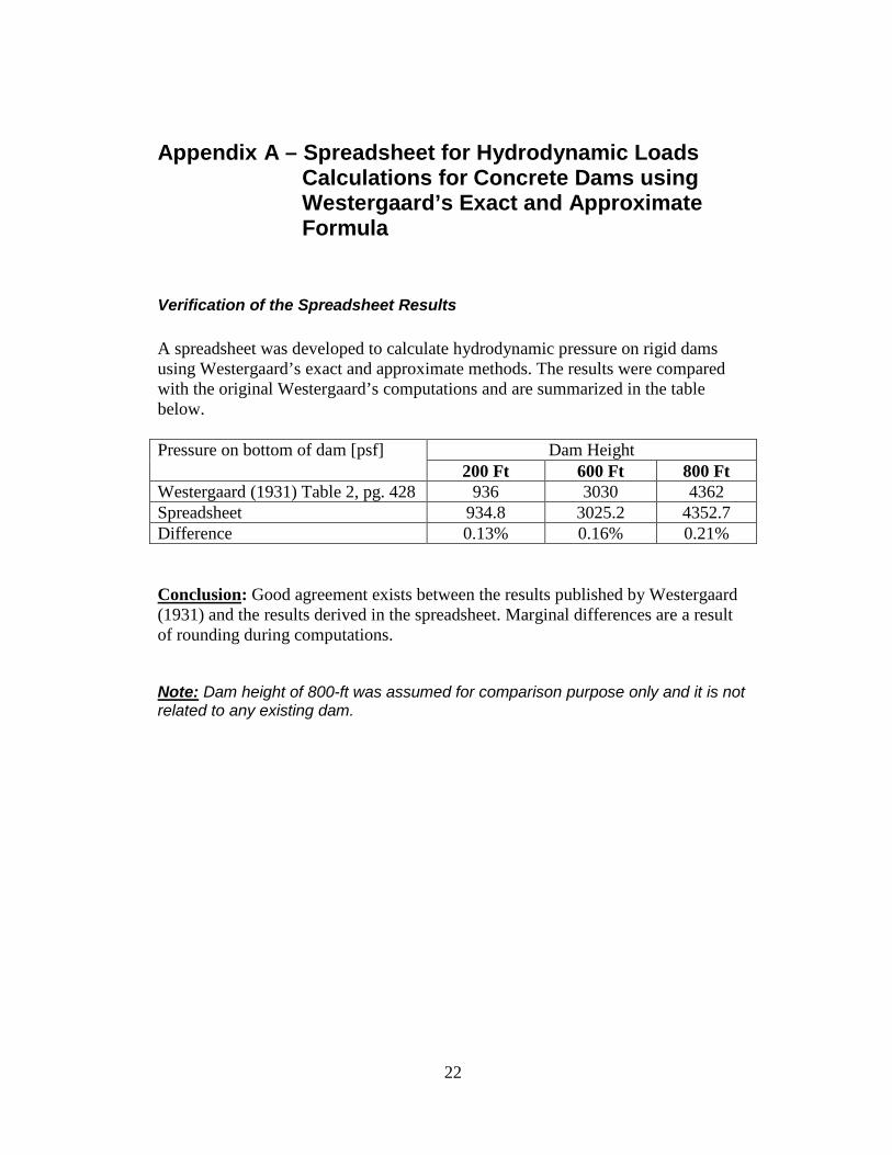
Verification of the Spreadsheet Results A spreadsheet was developed to calculate hydrodynamic pressure on rigid dams using Westergaard’s exact and approximate methods. The results were compared with the original Westergaard’s computations and are summarized in the table below. Pressure on bottom of dam [psf] Dam Height
200 Ft 600 Ft 800 Ft Westergaard (1931) Table 2, pg. 428 936 3030 4362 Spreadsheet 934.8 3025.2 4352.7 Difference 0.13% 0.16% 0.21% Conclusion: Good agreement exists between the results published by Westergaard (1931) and the results derived in the spreadsheet. Marginal differences are a result of rounding during computations.
Note: Dam height of 800-ft was assumed for comparison purpose only and it is not related to any existing dam.
23
Appendix B – Comparison of Hydrodynamic Loads for Concrete Dams per Westergaard’s Theory
Case 1: Dam Height 800 Ft. and T =4/3 Sec.
24
Figure B1a – Hydrodynamic pressure on dam H=800 Ft & T = 1.33 sec.
Figure B1b – Difference between the Approximate and Exact Westergaard formula
25
Case 2: Dam Height 600 Ft. and T =1.0 Sec.
26
Figure B2a – Hydrodynamic pressure on dam H=600 Ft & T = 1.0 sec.
Figure B2b – Difference between the Approximate and Exact Westergaard formula
27
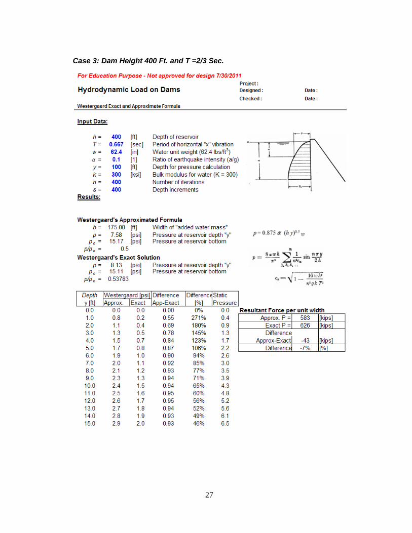
Case 3: Dam Height 400 Ft. and T =2/3 Sec.
28
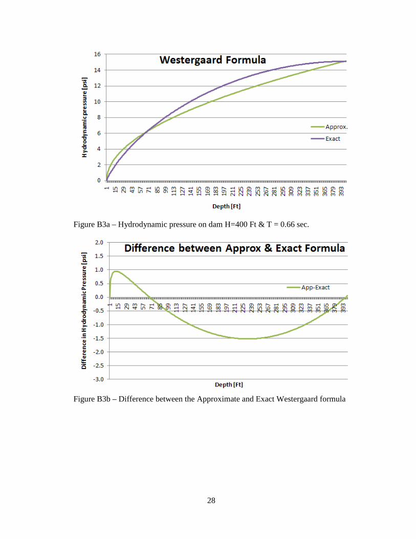
Figure B3a – Hydrodynamic pressure on dam H=400 Ft & T = 0.66 sec.
Figure B3b – Difference between the Approximate and Exact Westergaard formula
29
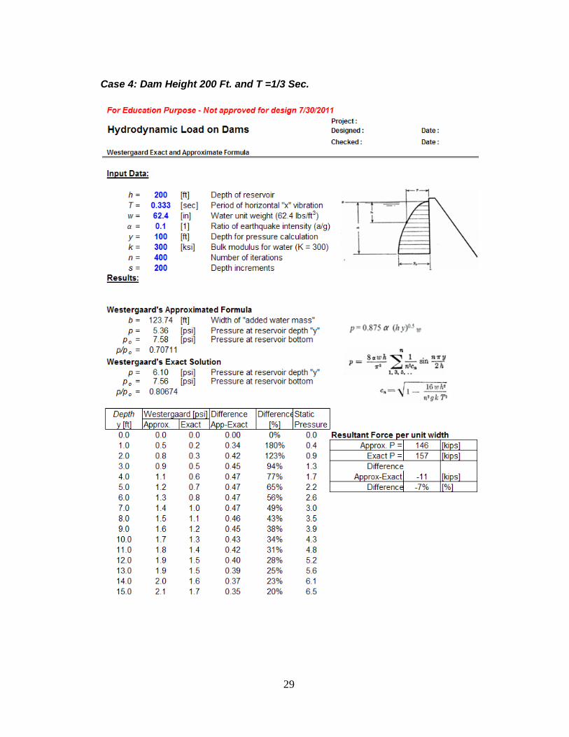
Case 4: Dam Height 200 Ft. and T =1/3 Sec.
30
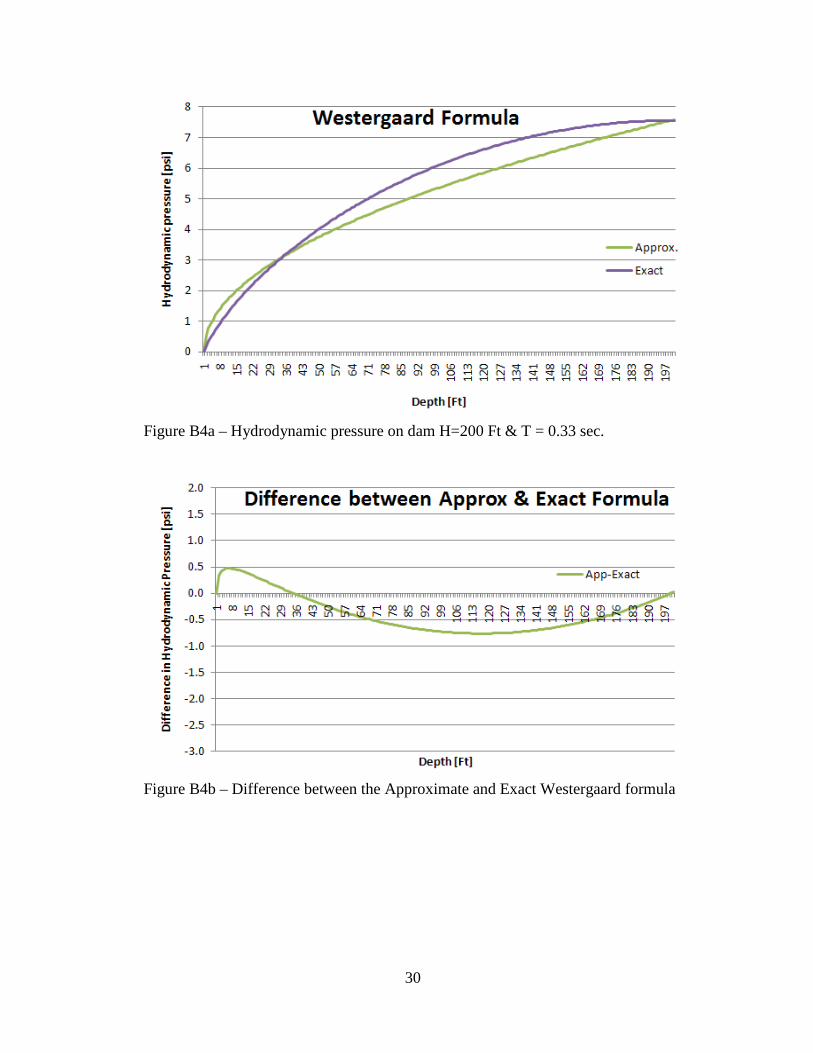
Figure B4a – Hydrodynamic pressure on dam H=200 Ft & T = 0.33 sec.
Figure B4b – Difference between the Approximate and Exact Westergaard formula
31
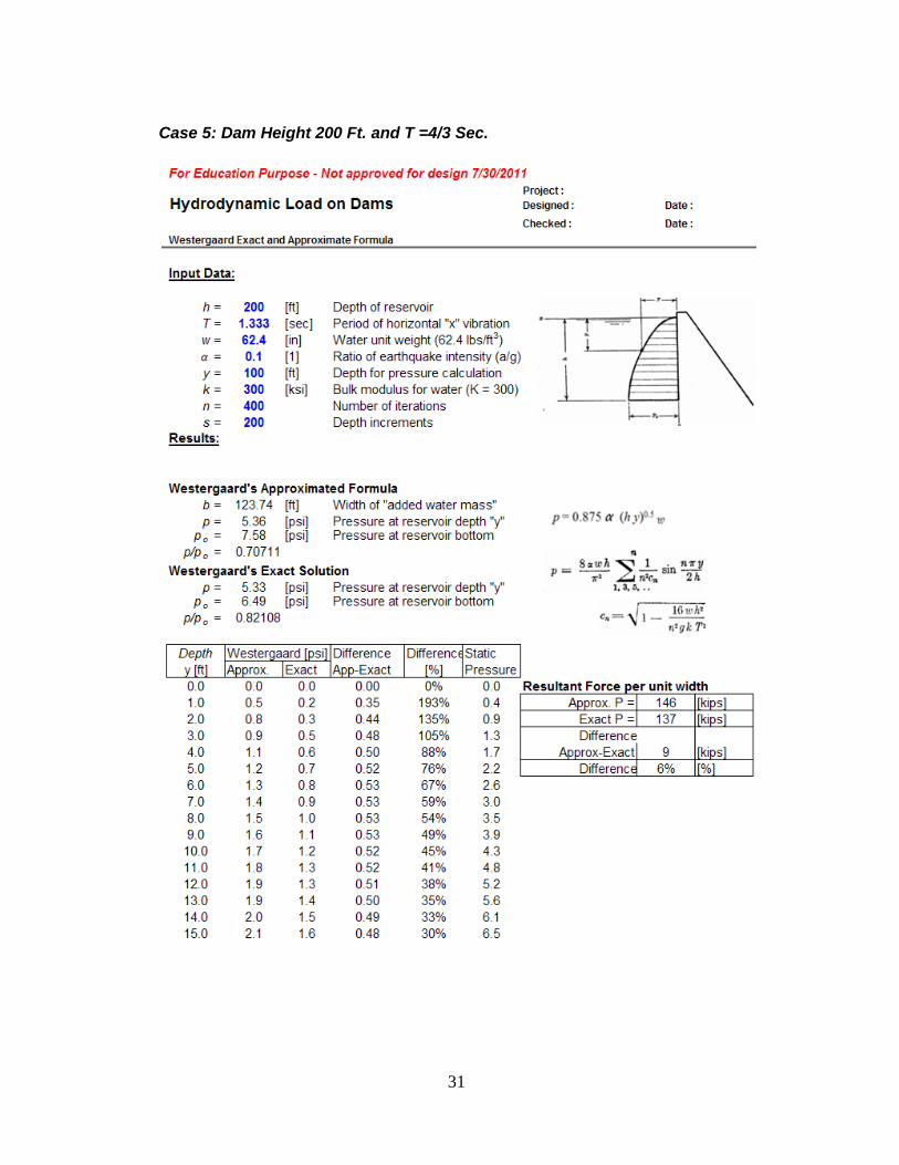
Case 5: Dam Height 200 Ft. and T =4/3 Sec.
32
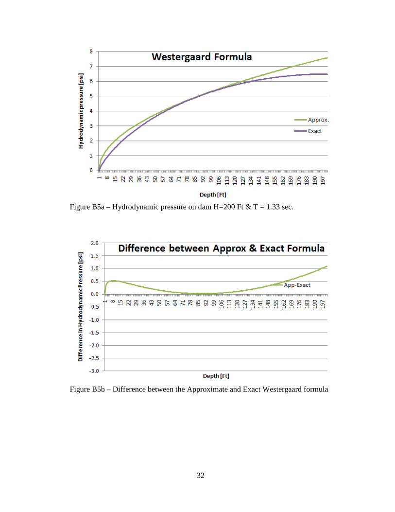
Figure B5a – Hydrodynamic pressure on dam H=200 Ft & T = 1.33 sec.
Figure B5b – Difference between the Approximate and Exact Westergaard formula
33
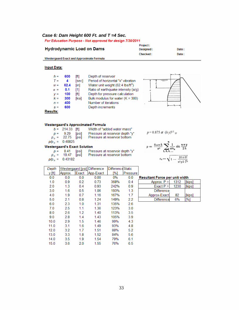
Case 6: Dam Height 600 Ft. and T =4 Sec.
34
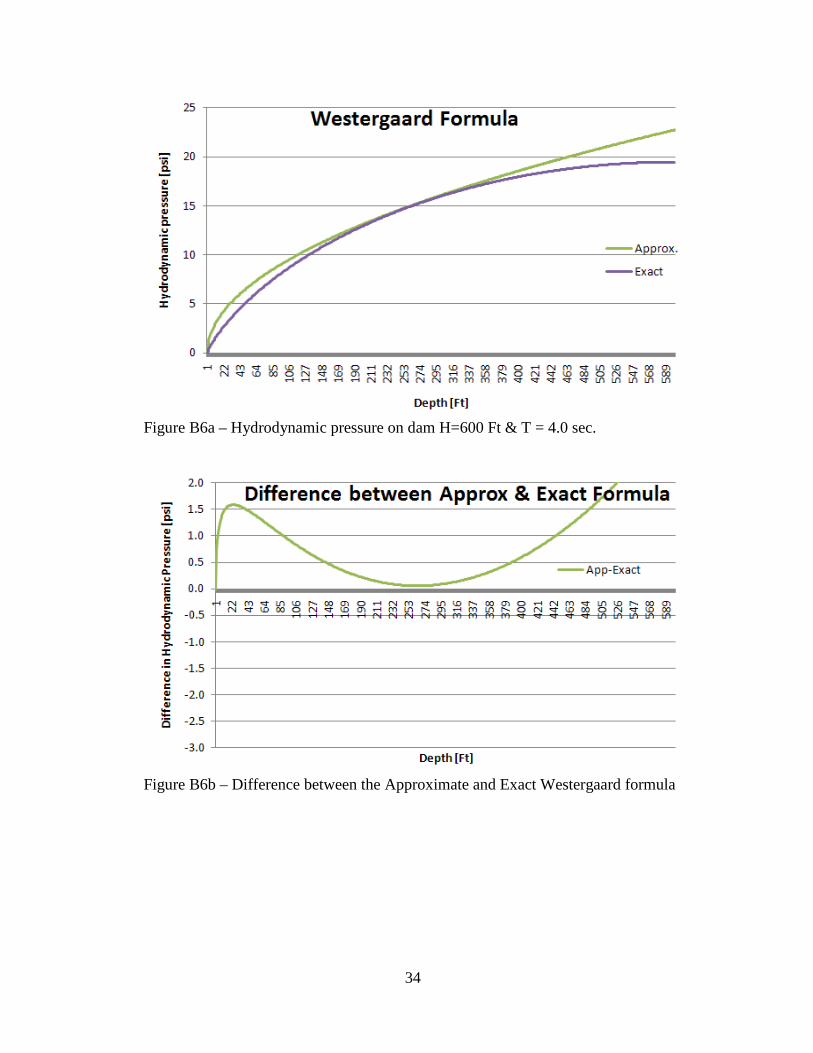
Figure B6a – Hydrodynamic pressure on dam H=600 Ft & T = 4.0 sec.
Figure B6b – Difference between the Approximate and Exact Westergaard formula