Embed Size (px)
Citation preview
73rd EAGE Conference & Exhibition incorporating SPE EUROPEC 2011 Vienna, Austria, 23-26 May 2011
J046Seismic Investigation of a Deep-seated MassMovement Assisting the Refurbishment of aPressure Tunnel in Tyrol, AustriaD. Kostial* (Pöyry Infra GmbH), W. Chwatal (Vienna University ofTechnology) & A. Freudenthaler (Pöyry Infra GmbH)
SUMMARYThe refurbishment of the Kaunertal hydroelectric power station, planned by the Tiroler Wasserkraft AG,requires a new water pressure tunnel crossing a deep-seated mass movement near the town Prutz in Tyrol,Austria. Preliminary studies including 2D and 3D refraction seismic surveys were carried out to determinethe optimum trail of this water pressure tunnel. The tunnel should not be influenced by the massmovement and at best should run under the mass movement. Therefore definition of the deepest slidingsurface of the mass movement but also the geotechnical condition of the moving mass was the main tasksof the seismic investigation. To obtain this information standard refraction seismology and refractionseismic tomography was applied. Because of high velocity structures near the surface the results of bothmethods are combined to construct the deepest sliding surface which was supported by the information ofdrillings and morphology, like the main scarps.
73rd EAGE Conference & Exhibition incorporating SPE EUROPEC 2011 Vienna, Austria, 23-26 May 2011
Introduction
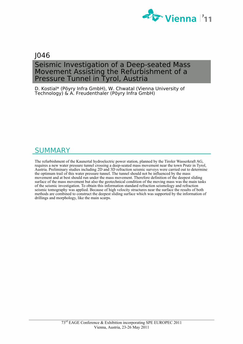
The Tiroler Wasserkraft AG plans the refurbishment and extension of the hydroelectric power plant Kaunertal. Therefore several possible positional variants for a new water pressure tunnel were investigated. One of these is located near the junction of the Kauner valley and the upper Inn valley and will cross, as the existent water pressure tunnel, a deep-seated mass movement next to the town Prutz (Fig 1). Because of the two valleys the mass movement has a triangle shape covering an area of almost 3 km2. The very slowly creeping rock mass shows a difference in elevation between the toe and the main scarp of about 900 m. Results from geodetic measurements show average surface displacements in the range between 5 to 10 centimetres per year. Geologically, the mass movement is situated in the north penninic Engadiner window (Brandner, 1980) and consists of interchanging phyllits, limestones and quartzites with single blocks of dolomite. A significant part of the preliminary studies were seismic measurements. Their main scope was to determine the geometry and structure of the mass movement for optimizing the trail for the new water pressure tunnel in this area, providing information like the compact rock line (main sliding surface), as well as internal structures of the mass movement and geotechnical conditions of the rock material. Within the mass movement a diverse rock quality from totally crashed to compact was to be expected. Therefore a combined 2D and 3D seismic survey was carried out, succeeding in a wide ranging visualization of the rock movement.
Prutz
main scarp
Kauner valley Inn valley
existent waterpressure tunnel
Figure 1 Overview of the mass movement at the junction Kauner valley and upper Inn valley in Tyrol, Austria; main scarp of the mass movement and existent water pressure tunnel are inserted
Method
To achieve the main scopes a 3D refraction seismic survey was established in the most probable area (near the peak Burgschrofen) of the planned water pressure tunnel. Many previous seismic investigations of mass movements (e.g. Chwatal et al., 2005) had shown that the seismic refraction method gives the best results for such cases. Additionally, 2D refraction lines were carried out to cover the whole mass movement (Fig 2).
73rd EAGE Conference & Exhibition incorporating SPE EUROPEC 2011 Vienna, Austria, 23-26 May 2011
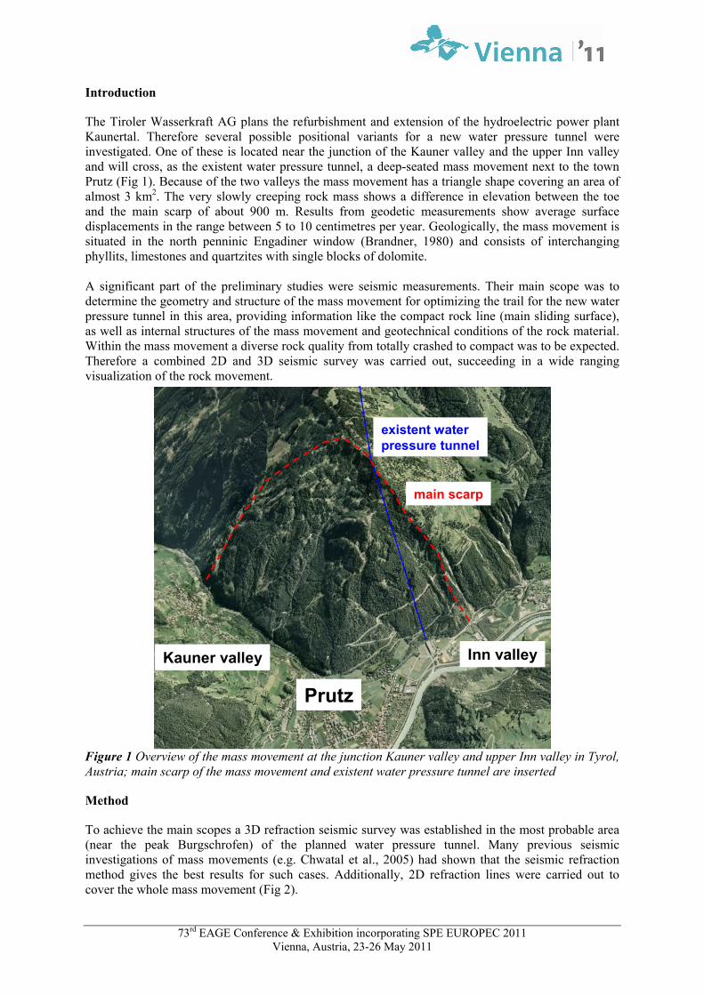
For the 3D seismic measurements a total amount of 417 seismic stations with a geophone distance of 20 m along 9 receiver lines was carried out. 143 shots, which were also executed between the receiver lines, with a nominal shot distance of approximately 100 m were performed in 2 – 3 m deep drillings using 1 kg of explosives. Moreover, three 2D seismic lines with a geophone distance of 8 m and a shot distance of 16 m extended the 3D seismic survey to the east. Altogether 546 seismic stations and about 280 shots, which were done in 1 m deep drillings with 200 g explosives, were executed for the 2D lines.
Figure 2 Map view of the 2D and 3D seismic survey; see legend for description The basic model of the 3D seismic was calculated by standard refraction seismology and refraction seismic tomography. The standard refraction seismology results in a boundary between the loose and the compact rock and therefore should represent the deepest sliding surface. The areal distribution of the seismic velocity of the whole rock mass is provided by refraction seismic tomography (Fig 3). Because of the intensive shooting at the 2D lines also reflection seismic processing was applied but reflections are barely visible in the results. The seismic processing and imaging was done with following procedures and products:
2D and 3D seismic refraction: PROMAX (Landmark Graphics) 2D reflection seismic: PROMAX (Landmark Graphics) 2D refraction tomography: RayFract (Intelligent Resources Inc.) 3D refraction tomography: Algorithm of Hole (Hole, 1992) Imaging and plotting cuts from the 3D data volume: GOCAD Final imaging: AutoCAD (Autodesk) and Surfer (Golden Software Inc.)
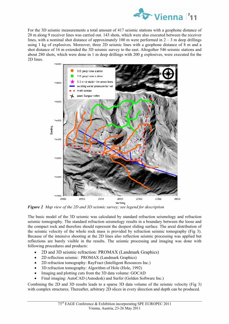
Combining the 2D and 3D results leads to a sparse 3D data volume of the seismic velocity (Fig 3) with complex structures. Thereafter, arbitrary 2D slices in every direction and depth can be produced.
73rd EAGE Conference & Exhibition incorporating SPE EUROPEC 2011 Vienna, Austria, 23-26 May 2011
P-wave velocity scale [m/s]1000 2000 3000 4000 5000 6000
N
Figure 3 Results of the3D refraction seismic tomography; 3D velocity field of the investigation area
Construction of the deepest sliding surface
The 3D velocity field of the refraction seismic tomography and the calculated surface of the standard refraction seismic form the basis to construct the boundary to the compact rock which is assumed to be the deepest sliding surface of the mass movement. Further information was mainly provided by the morphology of the mass movement, drillings and borehole logging. Because of high velocity zones in the moving mass near the surface which corresponds to big blocks of dolomite and discrepancies near the scarps the obtained surface of the standard refraction seismic, which should represent this boundary, has to be modified. Furthermore, because of the lack of information in parts of the mass movement an adequate interpolation is essential. This geotechnical modeling and depth imaging was done using following steps:
Extracting 14 slices located along the main direction (direction of movement - Northwest) of the mass movement and 12 slices perpendicular to the main direction (Southeast)
Extracting depths from the refractor and isopachs of P–wave velocity for 4000 and 4500 m/s from the refraction seismic tomography results for each 2D slice
Creation of the sliding surface at these slices based on the information of these values, considering the main scarps, an adequate interpolation and the information of drillings and borehole logs. The interpolation is based on the assumptions that there is a smooth movement zone which implements a relatively smooth model.
Interpolation (Kriging) of the mass movement geometry from these 26 slices and the drilling information.
Adequate smoothing of the modelled surface Merging of the sliding surface inside the mass movement with the topography model outside
the scarps Imaging of the result, which represents the stable rock (Fig 4)
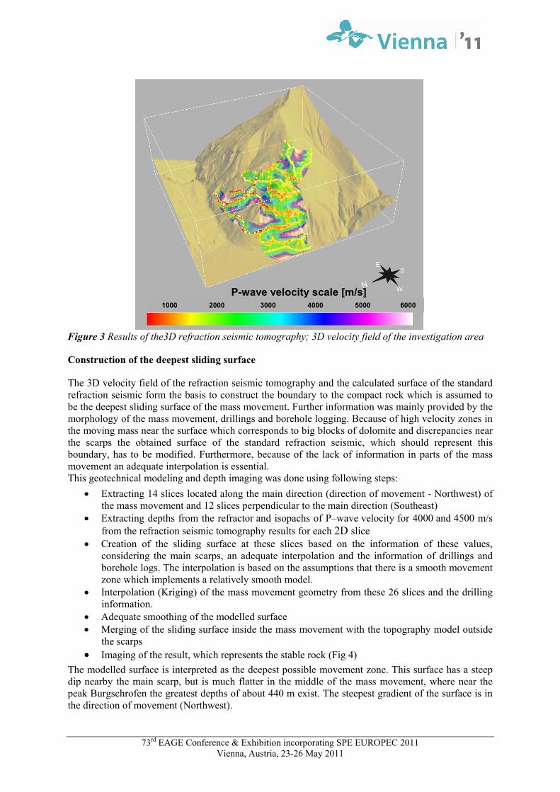
The modelled surface is interpreted as the deepest possible movement zone. This surface has a steep dip nearby the main scarp, but is much flatter in the middle of the mass movement, where near the peak Burgschrofen the greatest depths of about 440 m exist. The steepest gradient of the surface is in the direction of movement (Northwest).
73rd EAGE Conference & Exhibition incorporating SPE EUROPEC 2011 Vienna, Austria, 23-26 May 2011
Northing
Easting
Ele
vati
on
Elevation [m]
850
900
950
1000
1050
1100
1150
1200
1250
1300
1350
1400
1450
1500
1550
1600
1650
1700
1750
1800
1850
1900
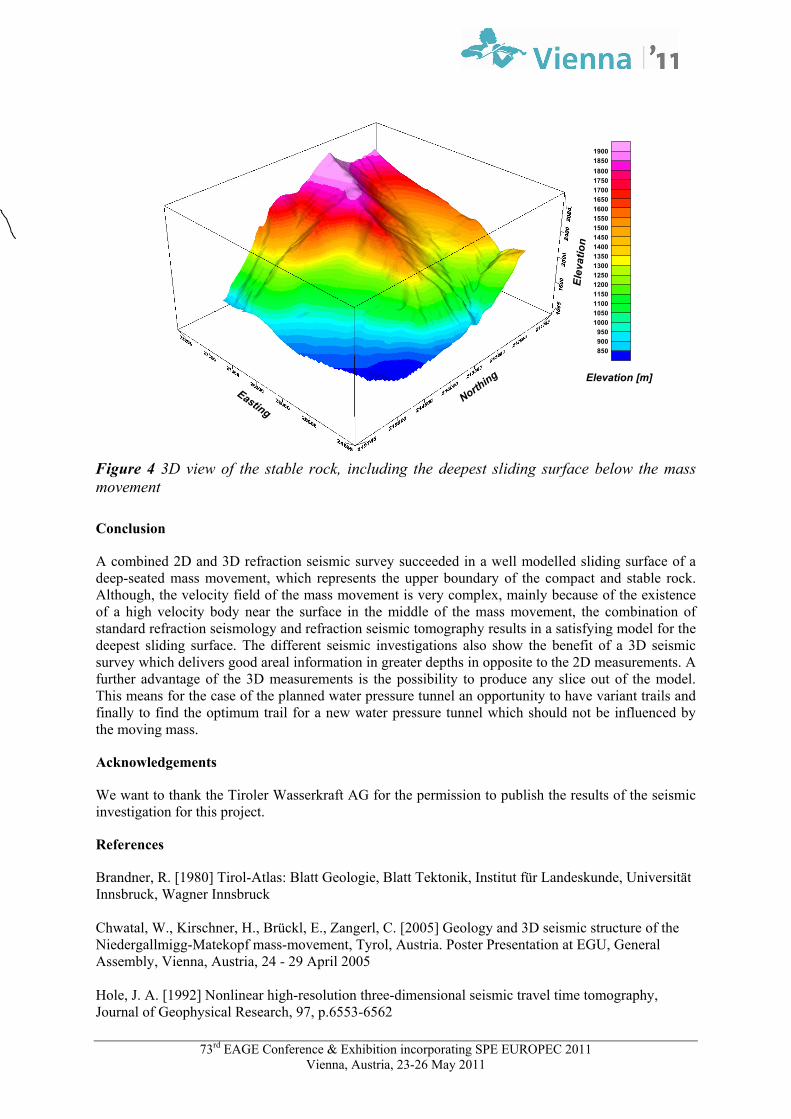
Figure 4 3D view of the stable rock, including the deepest sliding surface below the mass movement
Conclusion
A combined 2D and 3D refraction seismic survey succeeded in a well modelled sliding surface of a deep-seated mass movement, which represents the upper boundary of the compact and stable rock. Although, the velocity field of the mass movement is very complex, mainly because of the existence of a high velocity body near the surface in the middle of the mass movement, the combination of standard refraction seismology and refraction seismic tomography results in a satisfying model for the deepest sliding surface. The different seismic investigations also show the benefit of a 3D seismic survey which delivers good areal information in greater depths in opposite to the 2D measurements. A further advantage of the 3D measurements is the possibility to produce any slice out of the model. This means for the case of the planned water pressure tunnel an opportunity to have variant trails and finally to find the optimum trail for a new water pressure tunnel which should not be influenced by the moving mass.
Acknowledgements
We want to thank the Tiroler Wasserkraft AG for the permission to publish the results of the seismic investigation for this project.
References
Brandner, R. [1980] Tirol-Atlas: Blatt Geologie, Blatt Tektonik, Institut für Landeskunde, Universität Innsbruck, Wagner Innsbruck Chwatal, W., Kirschner, H., Brückl, E., Zangerl, C. [2005] Geology and 3D seismic structure of the Niedergallmigg-Matekopf mass-movement, Tyrol, Austria. Poster Presentation at EGU, General Assembly, Vienna, Austria, 24 - 29 April 2005 Hole, J. A. [1992] Nonlinear high-resolution three-dimensional seismic travel time tomography, Journal of Geophysical Research, 97, p.6553-6562