Embed Size (px)
Citation preview

Scan QR Code for more information usa.siemens.com/SEM3
Selection & Application Guide
SEM3™ - Embedded Micro Metering Module™

2
SEM3™ - Embedded Micro Metering Module™
Siemens Embedded Micro Metering Module (SEM3) is a modular metering solution for energy monitoring, data analysis, and sub billing applications. The flexible design allows for low, medium, and high density metering requirements to be met efficiently and economically using only a few standardized components that may be integrated into Panelboard, Switchboard, PDU, RPP, and Busplug products. SEM3 is pre-engineered to integrate into Siemens Panelboards, Switchboards, and Busplugs but is also offered for retrofit applications as well.
The SEM3, innovative and cost effective metering solution, can be incorporated into existing applications such as power monitoring, building automation, and sub-billing systems. SEM3 also has the flexibility to be installed as a standalone solution with real time data available from the controller’s standard built-in web pages. This metering product has two levels of accuracy to meet the market’s differing requirements and price points. This versatile system allows you to meter just the loads you need without the excess hardware and space requirements of traditional or competing solutions. SEM3 now has the ability to communicate via Modbus, BACnet, SNMP and SMTP. SEM3 web pages can also be set by the user to any of four languages (English, German, French or Spanish).
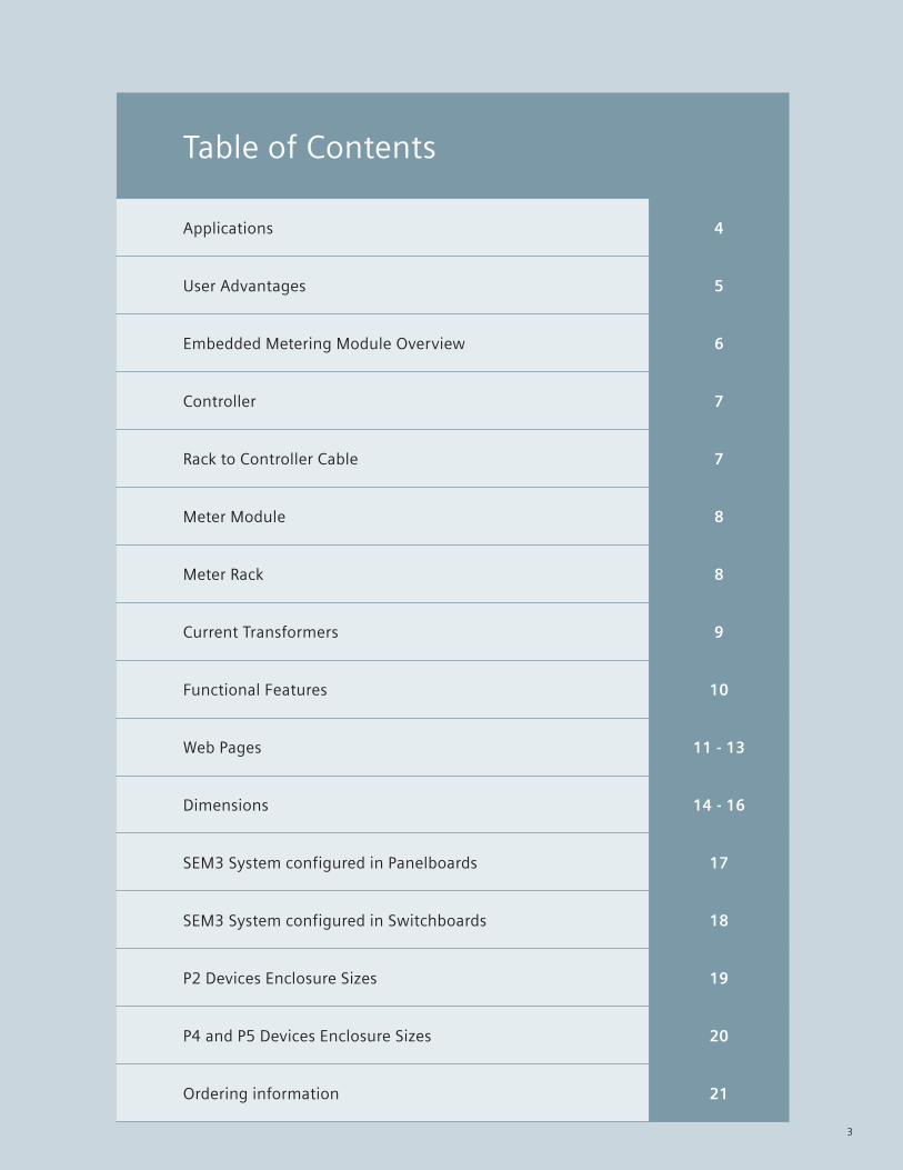
Table of Contents
Applications 4
User Advantages 5
Embedded Metering Module Overview 6
Controller 7
Rack to Controller Cable 7
Meter Module 8
Meter Rack 8
Current Transformers 9
Functional Features 10
Web Pages 11 - 13
Dimensions 14 - 16
SEM3 System configured in Panelboards 17
SEM3 System configured in Switchboards 18
P2 Devices Enclosure Sizes 19
P4 and P5 Devices Enclosure Sizes 20
Ordering information 21
3

4
Embedded Micro Metering Module™ SEM3 Applications
Multi FamilyThe SEM3 was designed with residential sub-billing applications in mind. The SEM3 can precisely measure the energy consumption of up to 45 poles per controllera in a space-savings Siemens panelboard solution. SEM3 can master a Siemens S7 1200 PLC configured to accept up to 44 digital inputs that may be configured in the controller as water or gas meter inputs and logged into the controller memory for extraction and transmit all of this critical billing information to third-party billing software as well as provide remote access via onboard webpage’s for quick system diagnostics and management.
The SEM3’s unique design allows you to expand by adding additional metered circuits in the future without expensive system modifications or retrofits. Its compact, integrated and cost effective design eliminates unsightly meter socket centers making your property more attractive to tenants and customers alike.
SEM3 is now approved by the state and city of New York as a sub billing meter system.SEM3 is approved by the state of California as a sub billing metering system.
aWith two controllers, a single Panelboard can be configured with more than 45 poles monitored in one enclosure. Two controllers can monitor up to 90 poles.
CommercialThe SEM3 is a full featured solution for commercial metering applications. The SEM3 can collect and aggregate your electrical data placing your metering information from multiple businesses, shops, offices, or other commercial units in one secure location right at your finger tips. Because SEM3 is much smaller than traditional metering solutions and is integrated into the electrical equipment, there is no need to waste space on large meter socket centers or electric meter rooms. This allows more square footage to be allocated to more profitable and rentable tenant space.
The standard built-in web pages, on-board data logging for kWh and up to 16 data points other user selected values, and web-based configuration will be features you will utilize often in the management of your facility. Whether to perform a quick check of a particular load, gather your energy readings, or make a change of a circuit for a tenant move, SEM3 is the metering solution for your commercial sites. The impressive accuracy of the system assures that costs are allocated properly, ultimately saving you money.
IndustrialThe SEM3 opens the door to conveniently and accurately measure your energy usage on all your facility loads. With its economical and efficiently designed package, SEM3 will be your metering standard to gather that next level of energy data within your facility. Whether you are interested in precisely monitoring energy consumption in data center server racks, allocating the energy costs of a factory by department or understanding which equipment in your facility is impacting your peak demand, SEM3 offers a solution that is ideal for your facility, large or small.
No matter what your load size, large distribution loads in a service switchboard or individual receptacle circuits in a panelboard, the SEM3 can be easily applied and monitor your power consumption with ease. And, don’t worry about your equipment, whether you’re utilizing a multiple section switchboard, a large P4/P5 panelboard, a simple P2 panelboard or even retrofitting to an existing piece of electrical equipment, the SEM3 metering system will seamlessly integrate into Siemens products or retrofit next to your existing gear to best suit your individual needs.

5
Embedded Micro Metering Module™ User Advantages
For Contractors:The SEM3 metering system provides an ideal sub-metering package for electrical contractors and installers. The installation of the SEM3 product when integrated is no different than installing any other Siemens panelboard or switchboard. With the integrated design of the SEM3, the Siemens electrical equipment will come pre-installed and internally wired with all the metering components required for field installation, saving days and weeks onsite. There are no separate enclosures to mount, no components to wire, no CTs to install, and no control power to run.
The installation of Siemens SEM3 Metered panelboards and switchboards has reduced installation time and risk for the installer. There are no components to keep track of or install in the field, so losing parts or mis-wiring them is eliminated. With the SEM3 already installed in the Siemens equipment, you simply pull and terminate the power cabling as you would a non-metered panel or switchboard. Then run your communications cabling to the panel and you’re complete. The mounting of bulky metering cabinets and installing additional wiring for traditional sub-meter panels can be removed from your estimations. Once you install Siemens SEM3 integrated meter equipment on a project, you won’t return to the traditional metering systems of years past.
For Property Owners:The SEM3 metering system offers several benefits to property owners who are looking to better manage their electrical costs. For those who are interested in sub-metering for billing tenants in an apartment complex or data center or for equipment load analysis in an industrial setting, the SEM3 can provide the visibility and data to achieve these goals.
The simple integration within Siemens panels and switchboards of the SEM3 metering system allows end users to maximize usable and billable square footage while minimizing total cost of ownership. Installation costs are less and time to occupancy is quicker when implementing SEM3 over traditional separate metering enclosures. The standard built-in web based tools within SEM3 allow you to easily and quickly see energy usage data, check loading on a particular circuit, or make changes to your metering as your facility grows. Adding meters later is easy with the modular design and rack system of SEM3. The SEM3 metering system puts the energy information at your finger tips to easily manage your loads, accurately distribute energy costs, plan for future expansions, and save money.
For Engineers and Consultants:Engineers and consultants will marvel at the size and capabilities of the SEM3 metering system. SEM3 is a full featured metering package that fits into Siemens panelboards and switchboards allowing for the elimination of separate metering systems in your design. With the SEM3 specified in your equipment, you receive a completely pre-engineered and tested metering system installed by the factory with components designed and manufactured to work together seamlessly. Installation in the field is reduced to simply installing a panelboard or switchboard, connecting the load cables and running your communications.
Implementing the SEM3 into your design, won’t take hours to figure out. The SEM3’s simple and reliable design takes care many design aspects. Siemens quotation and order systems fully support the integration of SEM3 allowing for quick design feedback, budgeting, ordering, and manufacture. No more selecting part numbers for meters, enclosures and CTs. Implementing SEM3 into your sub-metering applications will provide your customers with valuable information in a clean, pre-engineered solution that will meet your design expectations of space, cost and features.
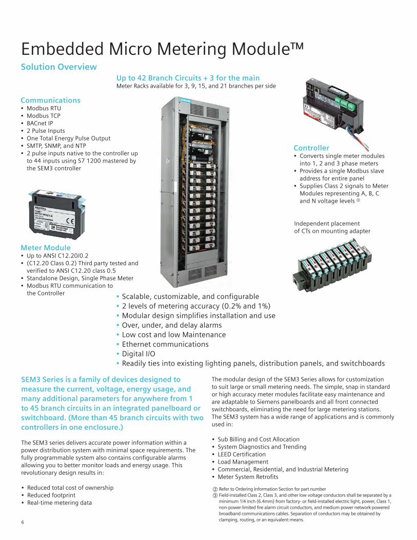
Embedded Micro Metering Module™ Solution Overview
6
SEM3 Series is a family of devices designed to measure the current, voltage, energy usage, and many additional parameters for anywhere from 1 to 45 branch circuits in an integrated panelboard or switchboard. (More than 45 branch circuits with two controllers in one enclosure.)
The SEM3 series delivers accurate power information within a power distribution system with minimal space requirements. The fully programmable system also contains configurable alarms allowing you to better monitor loads and energy usage. This revolutionary design results in:
• Reduced total cost of ownership• Reduced footprint• Real-time metering data
The modular design of the SEM3 Series allows for customization to suit large or small metering needs. The simple, snap in standard or high accuracy meter modules facilitate easy maintenance and are adaptable to Siemens panelboards and all front connected switchboards, eliminating the need for large metering stations. The SEM3 system has a wide range of applications and is commonly used in:
• Sub Billing and Cost Allocation• System Diagnostics and Trending • LEED Certification• Load Management• Commercial, Residential, and Industrial Metering• Meter System Retrofits
Communications• Modbus RTU• Modbus TCP• BACnet IP• 2 Pulse Inputs• One Total Energy Pulse Output• SMTP, SNMP, and NTP• 2 pulse inputs native to the controller up to 44 inputs using S7 1200 mastered by the SEM3 controller
Controller• Converts single meter modules into 1, 2 and 3 phase meters• Provides a single Modbus slave address for entire panel• Supplies Class 2 signals to Meter Modules representing A, B, C and N voltage levels c
Up to 42 Branch Circuits + 3 for the mainMeter Racks available for 3, 9, 15, and 21 branches per side
Meter Module• Up to ANSI C12.20/0.2• (C12.20 Class 0.2) Third party tested and verified to ANSI C12.20 class 0.5• Standalone Design, Single Phase Meter • Modbus RTU communication to the Controller •Scalable, customizable, and configurable
• 2 levels of metering accuracy (0.2% and 1%)• Modular design simplifies installation and use• Over, under, and delay alarms• Low cost and low Maintenance• Ethernet communications• Digital I/O• Readily ties into existing lighting panels, distribution panels, and switchboards
Independent placementof CTs on mounting adapter
bRefer to Ordering Information Section for part number c Field-installed Class 2, Class 3, and other low voltage conductors shall be separated by a minimum 1/4 inch (6.4mm) from factory- or field-installed electric light, power, Class 1, non-power-limited fire alarm circuit conductors, and medium power network-powered broadband communications cables. Separation of conductors may be obtained by clamping, routing, or an equivalent means.
7
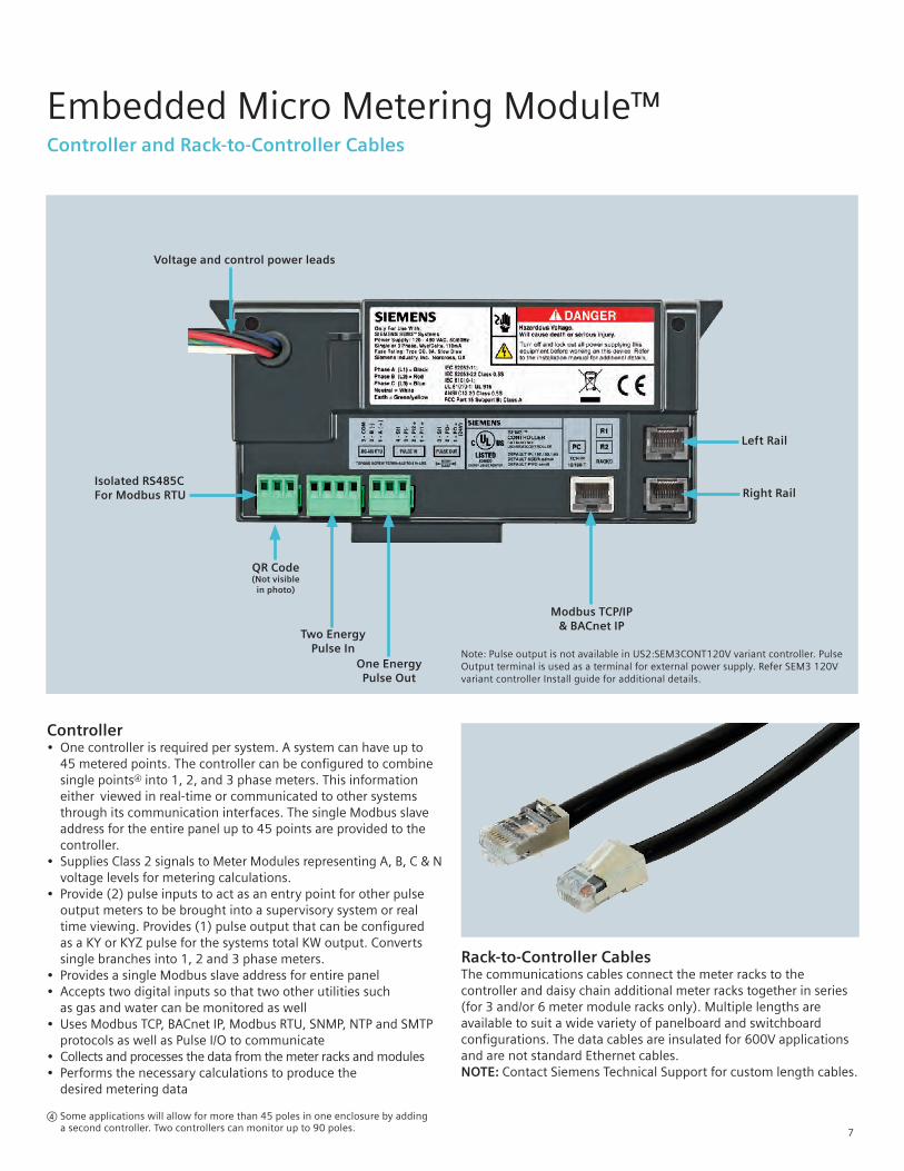
Embedded Micro Metering Module™ Controller and Rack-to-Controller Cables
Controller• One controller is required per system. A system can have up to 45 metered points. The controller can be configured to combine single pointsd into 1, 2, and 3 phase meters. This information either viewed in real-time or communicated to other systems through its communication interfaces. The single Modbus slave address for the entire panel up to 45 points are provided to the controller.• Supplies Class 2 signals to Meter Modules representing A, B, C & N voltage levels for metering calculations.• Provide (2) pulse inputs to act as an entry point for other pulse output meters to be brought into a supervisory system or real time viewing. Provides (1) pulse output that can be configured as a KY or KYZ pulse for the systems total KW output. Converts single branches into 1, 2 and 3 phase meters.• Provides a single Modbus slave address for entire panel • Accepts two digital inputs so that two other utilities such as gas and water can be monitored as well• Uses Modbus TCP, BACnet IP, Modbus RTU, SNMP, NTP and SMTP protocols as well as Pulse I/O to communicate• Collects and processes the data from the meter racks and modules• Performs the necessary calculations to produce the desired metering data
Rack-to-Controller Cables The communications cables connect the meter racks to the controller and daisy chain additional meter racks together in series (for 3 and/or 6 meter module racks only). Multiple lengths are available to suit a wide variety of panelboard and switchboard configurations. The data cables are insulated for 600V applications and are not standard Ethernet cables. NOTE: Contact Siemens Technical Support for custom length cables.
Two Energy Pulse In
Modbus TCP/IP & BACnet IP
Voltage and control power leads
One Energy Pulse Out
Isolated RS485CFor Modbus RTU
Left Rail
Right Rail
QR Code(Not visible
in photo)
Note: Pulse output is not available in US2:SEM3CONT120V variant controller. Pulse Output terminal is used as a terminal for external power supply. Refer SEM3 120V variant controller Install guide for additional details.
d Some applications will allow for more than 45 poles in one enclosure by adding a second controller. Two controllers can monitor up to 90 poles.
8
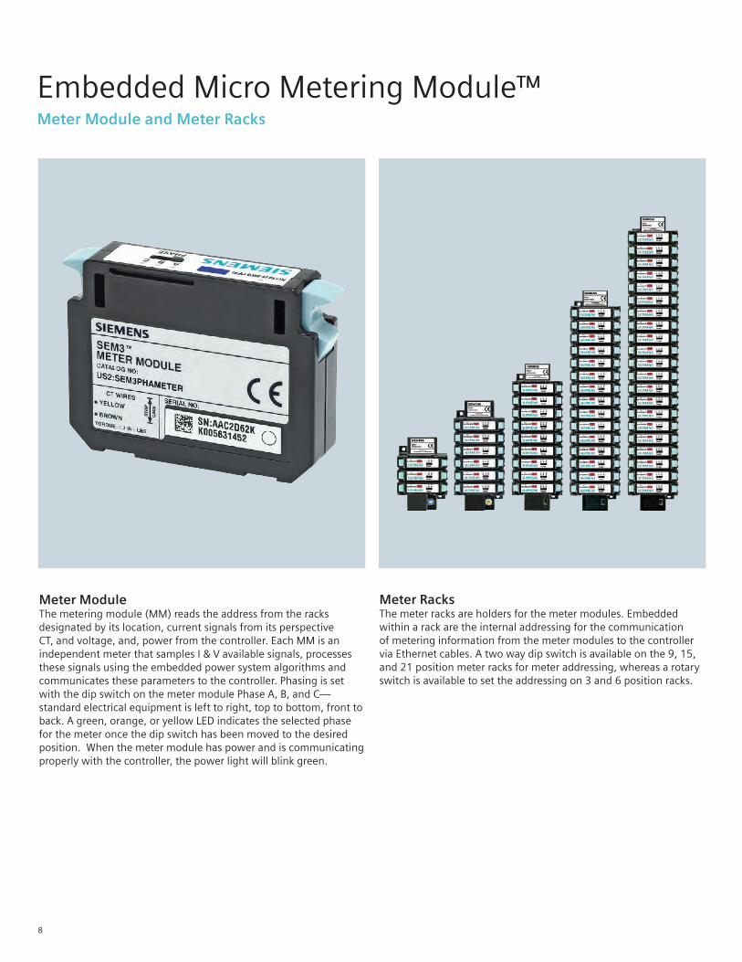
Embedded Micro Metering Module™ Meter Module and Meter Racks
Meter ModuleThe metering module (MM) reads the address from the racks designated by its location, current signals from its perspective CT, and voltage, and, power from the controller. Each MM is an independent meter that samples I & V available signals, processes these signals using the embedded power system algorithms and communicates these parameters to the controller. Phasing is set with the dip switch on the meter module Phase A, B, and C— standard electrical equipment is left to right, top to bottom, front to back. A green, orange, or yellow LED indicates the selected phase for the meter once the dip switch has been moved to the desired position. When the meter module has power and is communicating properly with the controller, the power light will blink green.
Meter RacksThe meter racks are holders for the meter modules. Embedded within a rack are the internal addressing for the communication of metering information from the meter modules to the controller via Ethernet cables. A two way dip switch is available on the 9, 15, and 21 position meter racks for meter addressing, whereas a rotary switch is available to set the addressing on 3 and 6 position racks.
9
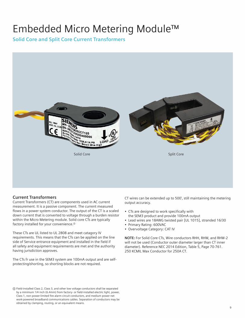
Embedded Micro Metering Module™ Solid Core and Split Core Current Transformers
Current TransformersCurrent Transformers (CT) are components used in AC current measurement. It is a passive component. The current measured flows in a power system conductor. The output of the CT is a scaled down current that is converted to voltage through a burden resistor within the Micro Metering module. Solid core CTs are typically factory installed for your convenience.e
These CTs are UL listed to UL 2808 and meet catagory IV requirements. This means that the CTs can be applied on the line side of Service entrance equipment and installed in the field if all safety and equipment requirements are met and the authority having jurisdiction approves.
The CTs fr use in the SEM3 system are 100mA output and are self-protecting/shorting, so shorting blocks are not required.
eField-installed Class 2, Class 3, and other low voltage conductors shall be separated by a minimum 1/4 inch (6.4mm) from factory- or field-installed electric light, power, Class 1, non-power-limited fire alarm circuit conductors, and medium power net work-powered broadband communications cables. Separation of conductors may be obtained by clamping, routing, or an equivalent means.
CT wires can be extended up to 500', still maintaining the metering output accuracy. • CTs are designed to work specifically with the SEM3 product and provide 100mA output• Lead wires are 18AWG twisted pair [UL 1015], stranded 16/30• Primary Rating: 600VAC• Overvoltage Category: CAT IV
NOTE: For Solid Core CTs, Wire conductors RHH, RHW, and RHW-2 will not be used (Conductor outer diameter larger than CT inner diameter). Reference NEC 2014 Edition, Table 5, Page 70-761. 250 KCMIL Max Conductor for 250A CT.
Split CoreSolid Core
10
Embedded Micro Metering Module™ Functional Features
Instantaneous values
VoltagePhase-Phase (2,3 Phase) Phase-Neutral (1 phase)
Currents Per Phase
Active, Reactive, and Apparent power (kW, kVAR, kVA)
Per Phase and Total
Power Factor Per Phase and Total
Frequency 45…64 Hz
Phase Angle
Current Demand - kW demand Per Phase and Total
Max Values Current Demand
Current
kW Demand
kW
Average Values Voltage
Current
Energy Measurement
Active Energy (kWh)
Reactive Energy (kVARh)
Apparent Energy (kVAh)
Alarming / Monitoring Functions
Phase Loss
Over Current Warning
Over Current Alarm
Over kW Demand Alarm
Under/Over Voltage Alarm
Communications
Ethernet - Modbus TCP/IP, BACnet IP, SNMP, NTP and SMTP
Integrated RJ45 port as standard (can support 3 masters and 1 integrated web access si-
multaneously)10/100 base-T (100 Mbit/sec)
Modbus RTU Integrated RS485 port Support of baud rates of 9600, 19.2K and 38.4K
Pulse Input 1/2Monitors Meters (Water, Gas, etc.)
Form A / C 28 VDC (± 4)
kWhr Pulse Output 1 (if more than 2 pulse inputs are needed, use S7 1200 PLC; 44 additional inputs)
Form A / C max 30 VDC
General
Password Protection
Technical Data
Measurement Types 1, 2, or 3 phase
Measurement Accuracy - Standard ANSI C12.16/1
Measurement Accuracy - High ANSI C12.20/0.2
Measured Voltage without Transformer Delta/Wye 480V max
Current Inputs 100 mA output CTs 50-2000A CTs
Power Supply (US2:SEM3CONTROLLER) AC 120-480 VAC (±10%)
External Power Supply Voltage (US2:SEM3CONT120V) AC/DC 120VAC/125VDC +/- 10%
Degree of Protection Front / RearIP52 - NEMA 12 IP20 - NEMA 1A
Operating Temperature °C / °F-10°C to 65°C 14°F to 149°F
Safety Standards and Compliance
CSA C22.2 No. 1010-1 Safety Requirements for Electrical Equipment for Measurement
UL916 Energy Management Equipment
IEC 62052-11; IEC 62053-22 Class 0.5S; UL61010-1 (IEC 61010-1) Test and Measurement Equipment
Current transformer listed to UL 2808 Energy Monitoring Current Transformers
Approved by New York City PSC (Public Service Commission) for sub billing application
CTEP Certified (California Type Evaluation Program) by CDFA (California Departmentof Food and Agriculture), a division of Measurement Standards, CA for sub billing applications
Approved by third party NRTL (Nationally Recognized Test Lab) for ANSI C12.20 standards
Note: External Powered SEM3 Controller Variant (US2:SEM3CONT120V) complies with UL 61010 and cUL standards only.
11
Embedded Micro Metering Module™ SEM3 Web Pages
Cutting Edge Web Enabled Configuration and Real-Time Data Display
View your system voltage, current, power and energy readings from anywhere using standard web browsers like Chrome and Internet Explorer.
Everyday functionality, including system status, alarm status, total kWh, etc.
Web enabled configuration provides authenticated access to common functions:
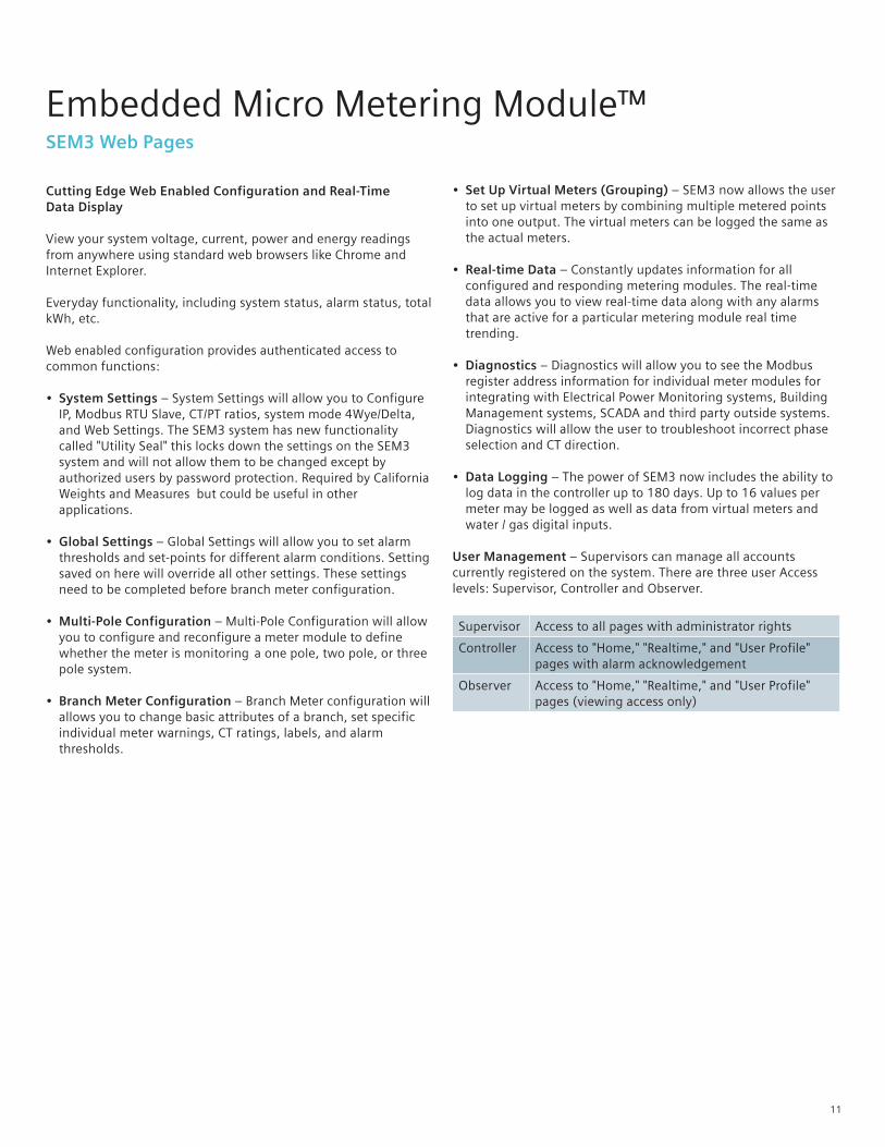
• System Settings – System Settings will allow you to Configure IP, Modbus RTU Slave, CT/PT ratios, system mode 4Wye/Delta, and Web Settings. The SEM3 system has new functionality called "Utility Seal" this locks down the settings on the SEM3 system and will not allow them to be changed except by authorized users by password protection. Required by California Weights and Measures but could be useful in other applications.
• Global Settings – Global Settings will allow you to set alarm thresholds and set-points for different alarm conditions. Setting saved on here will override all other settings. These settings need to be completed before branch meter configuration.
• Multi-Pole Configuration – Multi-Pole Configuration will allow you to configure and reconfigure a meter module to define whether the meter is monitoring a one pole, two pole, or three pole system.
• Branch Meter Configuration – Branch Meter configuration will allows you to change basic attributes of a branch, set specific individual meter warnings, CT ratings, labels, and alarm thresholds.
• Set Up Virtual Meters (Grouping) – SEM3 now allows the user to set up virtual meters by combining multiple metered points into one output. The virtual meters can be logged the same as the actual meters.
• Real-time Data – Constantly updates information for all configured and responding metering modules. The real-time data allows you to view real-time data along with any alarms that are active for a particular metering module real time trending.
• Diagnostics – Diagnostics will allow you to see the Modbus register address information for individual meter modules for integrating with Electrical Power Monitoring systems, Building Management systems, SCADA and third party outside systems. Diagnostics will allow the user to troubleshoot incorrect phase selection and CT direction.
• Data Logging – The power of SEM3 now includes the ability to log data in the controller up to 180 days. Up to 16 values per meter may be logged as well as data from virtual meters and water / gas digital inputs.
User Management – Supervisors can manage all accounts currently registered on the system. There are three user Access levels: Supervisor, Controller and Observer.
Supervisor Access to all pages with administrator rights
Controller Access to "Home," "Realtime," and "User Profile" pages with alarm acknowledgement
Observer Access to "Home," "Realtime," and "User Profile" pages (viewing access only)
12
Embedded Micro Metering Module™ SEM3 Web Pages
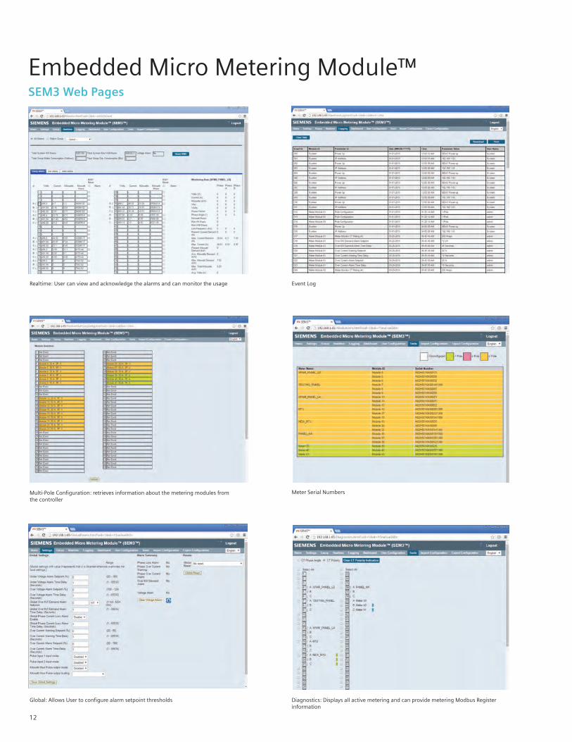
Realtime: User can view and acknowledge the alarms and can monitor the usage Event Log
Multi-Pole Configuration: retrieves information about the metering modules from the controller
Meter Serial Numbers
Global: Allows User to configure alarm setpoint thresholds Diagnostics: Displays all active metering and can provide metering Modbus Register information
13
Event Log
Embedded Micro Metering Module™ SEM3 Web Pages
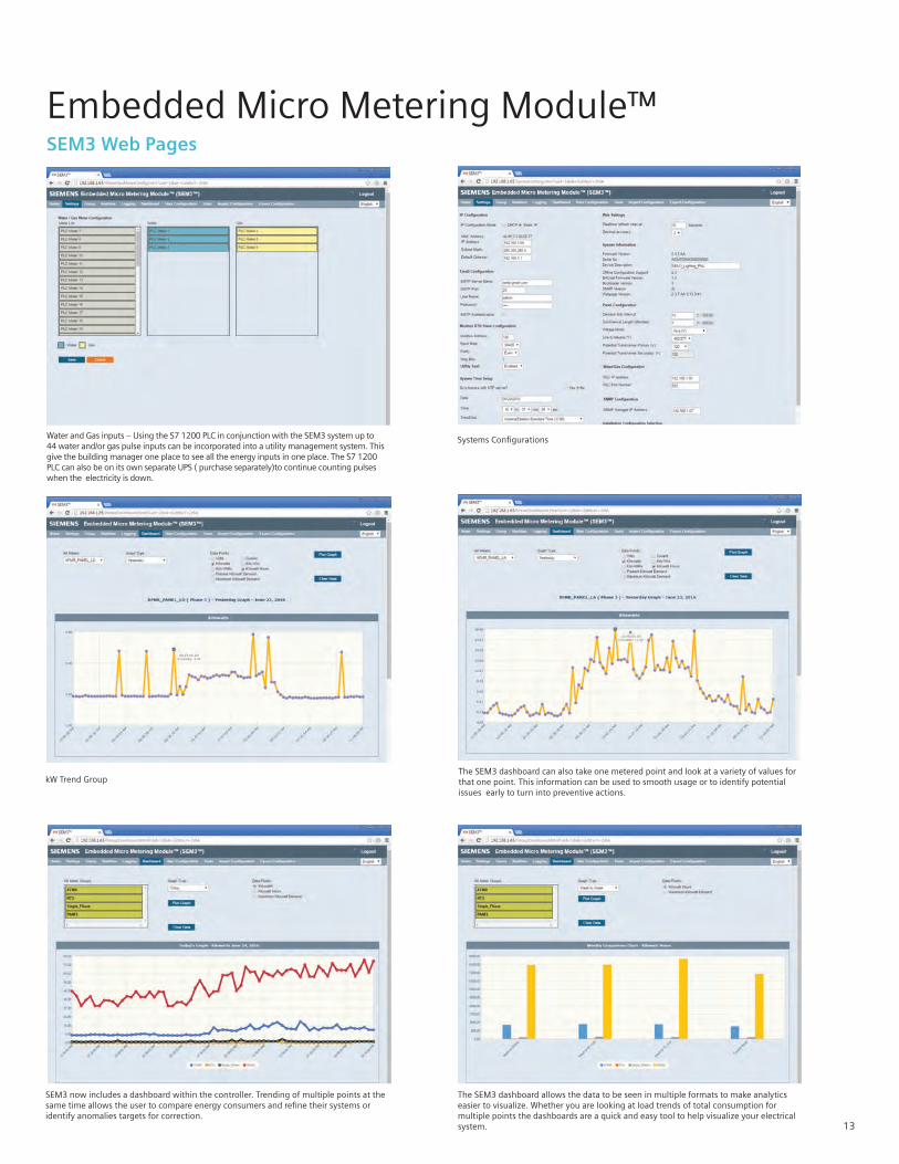
Water and Gas inputs – Using the S7 1200 PLC in conjunction with the SEM3 system up to 44 water and/or gas pulse inputs can be incorporated into a utility management system. This give the building manager one place to see all the energy inputs in one place. The S7 1200 PLC can also be on its own separate UPS ( purchase separately)to continue counting pulses when the electricity is down.
kW Trend Group
SEM3 now includes a dashboard within the controller. Trending of multiple points at the same time allows the user to compare energy consumers and refine their systems or identify anomalies targets for correction.
Systems Configurations
The SEM3 dashboard can also take one metered point and look at a variety of values for that one point. This information can be used to smooth usage or to identify potential issues early to turn into preventive actions.
The SEM3 dashboard allows the data to be seen in multiple formats to make analytics easier to visualize. Whether you are looking at load trends of total consumption for multiple points the dashboards are a quick and easy tool to help visualize your electrical system.
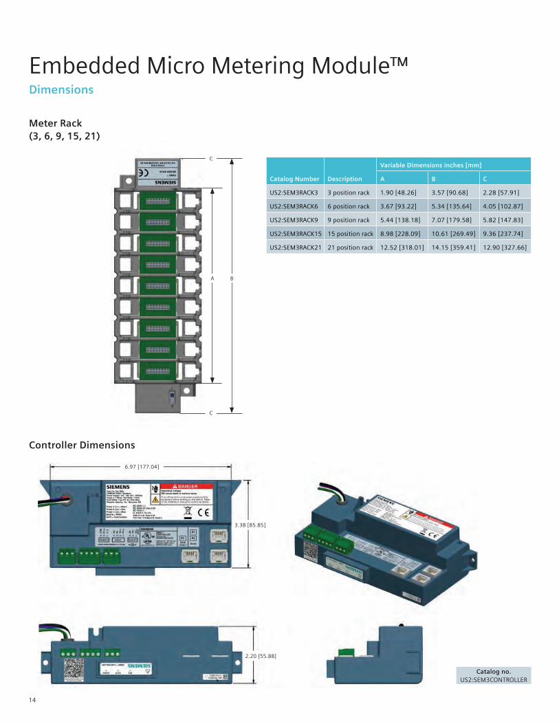
Controller Dimensions
6.97 [177.04]
3.38 [85.85]
2.20 [55.88]
14
Embedded Micro Metering Module™ Dimensions
Catalog Number Description
Variable Dimensions inches [mm]
A B C
US2:SEM3RACK3 3 position rack 1.90 [48.26] 3.57 [90.68] 2.28 [57.91]
US2:SEM3RACK6 6 position rack 3.67 [93.22] 5.34 [135.64] 4.05 [102.87]
US2:SEM3RACK9 9 position rack 5.44 [138.18] 7.07 [179.58] 5.82 [147.83]
US2:SEM3RACK15 15 position rack 8.98 [228.09] 10.61 [269.49] 9.36 [237.74]
US2:SEM3RACK21 21 position rack 12.52 [318.01] 14.15 [359.41] 12.90 [327.66]
Catalog no.US2:SEM3CONTROLLER
Meter Rack (3, 6, 9, 15, 21)
A B
C
C
Embedded Micro Metering Module™ Dimensions
Current Transformer – Solid Core
Description Catalog Number
Dimensions inches [mm]
A B C D E F G
Solid Core CT 50:0.1 US2:SEM3SCCT50 1.40 [35.56]
0.38 [9.65]
0.20 [5.08]
0.92 [23.37]
2.12 [53.85]
0.74 [18.80]
0.37 [9.40]
Solid Core CT 125:0.1 US2:SEM3SCCT1251.40 [35.56]
0.66 [16.76]
0.20 [5.08]
0.92 [23.37]
2.16 [54.86]
0.74 [18.80]
0.37 [9.40]
Solid Core CT 250:0.1 US2:SEM3SCCT2501.90 [48.26]
0.93 [23.62]
0.20 [5.08]
0.92 [23.37]
2.75 [69.85]
0.78 [19.81]
0.39 [9.91]
Solid Core CT 400:0.1 US2:SEM3SCCT400 2.62 [66.55]
1.60 [40.64]
0.20 [5.08]
0.92 [23.37]
3.62 [91.95]
0.78 [19.81]
0.39 [9.91]
Solid Core CT 600:0.1 US2:SEM3SCCT600 3.74 [95.00]
2.30 [58.42]
0.24 [6.10]
0.92 [23.37]
4.66 [118.36]
0.78 [19.81]
0.39 [9.91]
Solid Core CT 800:0.1 US2:SEM3SCCT800 4.05 [102.87]
2.60 [66.04]
0.24 [6.10]
0.92 [23.37]
5.05 [128.27]
0.98 [24.89]
0.49 [12.45]
Solid Core CT 1200:0.1 US2:SEM3SCCT1200 4.56 [115.82]
2.80 [71.12]
0.24 [6.10]
0.92 [23.37]
5.57 [141.48]
0.98 [24.89]
0.49 [12.45]
Solid Core CT 1600:0.1 [square]
US2:SEM3SCCT1600 4.50 [114.3]
4.50 [114.3]
7.68 [195.07]
7.14 [181.36]
1.59 [40.39]
1.48 [37.59] –
Solid Core CT 2000:0.1 [square]
US2:SEM3SCCT2000 4.50 [114.3]
4.50 [114.3]
7.68 [195.07]
7.14 [181.36]
1.59 [40.39]
1.48 [37.59]
–
Dimensions inches [mm]
Description Catalog Number A B C D E F
Split Core CT 50:0.1 7KT1280-5MA00 0.50 [12.7]
0.50 [12.7]
2.40 [60.96]
2.69 [68.33]
0.95 [24.13]
1.10 [27.94]
Split Core CT 125:0.1 7KT1280-5MA01 0.75 [19.05]
0.75 [19.05]
2.40 [60.96]
2.69 [68.33]
0.83 [20.96]
0.94 [23.88]
Split Core CT 250:0.1 7KT1280-5MA02 1.00 [25.4]
1.00 [25.4]
2.87 [72.9]
3.24 [82.3]
0.94 [23.75]
1.11 [28.19]
Split Core CT 400:0.1 7KT1280-5MA03 1.50 [38.1]
1.50 [38.1]
3.60 [91.44]
3.75 [95.25]
1.05 [26.67]
1.15 [29.21]
Split Core CT 600:0.1 7KT1280-5MA04 2.14 [54.36]
2.17 [55.12]
4.72 [119.89]
4.32 [109.73]
1.28 [32.39]
1.15 [29.21]
Split Core CT 800:0.1 7KT1280-5MA05 3.00 [76.2]
3.14 [79.76]
5.56 [141.22]
5.27 [133.86]
1.21 [30.73]
1.16 [29.46]
Split Core CT 1200:0.1 7KT1280-5MA06 3.27 [83.06]
3.02 [76.71]
6.48 [164.59]
5.69 [144.53]
1.73 [43.94]
1.48 [37.59]
Split Core CT 1600:0.1 7KT1280-5MA07 4.50 [114.3]
4.50 [114.3]
7.68 [195.07]
7.14 [181.36]
1.59 [40.39]
1.48 [37.59]
Split Core CT 2000:0.1 7KT1280-5MA08 4.50 [114.3]
4.50 [114.3]
7.68 [195.07]
7.14 [181.36]
1.59 [40.39]
1.48 [37.59]
Current Transformer – Split Core
F C
A
D B
E
A
B
C
D
E
FG
G
F C
A
D B
E
15
Catalog Number Description
Variable Dimensions inches [mm]
A B C
US2:SEM3RACK3 3 position rack 1.90 [48.26] 3.57 [90.68] 2.28 [57.91]
US2:SEM3RACK6 6 position rack 3.67 [93.22] 5.34 [135.64] 4.05 [102.87]
US2:SEM3RACK9 9 position rack 5.44 [138.18] 7.07 [179.58] 5.82 [147.83]
US2:SEM3RACK15 15 position rack 8.98 [228.09] 10.61 [269.49] 9.36 [237.74]
US2:SEM3RACK21 21 position rack 12.52 [318.01] 14.15 [359.41] 12.90 [327.66]
Meter Module
Embedded Micro Metering Module™ Dimensions
Description Catalog No.
Meter - Standard Accuracy 1% with Pulse Output US2:SEM3PLAMETER
Meter - High Accuracy 0.2% with Pulse Output US2:SEM3PHAMETER
2.06 [52.22]
1.58 [40.13]
.49 [12.45]
16
17
SEM3 for use in Siemens Panelboards
Type P2: Enclosure • Available in a NEMA 1, 3R, or 12 rated enclosure. • Minimum width & depth: 24” width x 5.75” depth • Height: Up to 74" depending on branch breaker selection - Addition of monitoring on some mains (primary and subfeed) may require additional box length. In these cases the box will be increased to the next size available as a standard design. - In cases where enclosure size is increased all multi-section panels will be increased to match the largest section.
Controller SEM3 controller is mounted in unit space opposite of the feed location specified in COMPAS (i.e., bottom mount for top feed) and will require 3” of unit space. Each controller will be powered by direct tap connection to the panel section bus. Each controller can monitor up to 45 circuits. Applications that require monitoring more than 45 circuits will require additional controllers.
Current Transformers (CTs)Five sizes of CTs are available for use in the P2 panel: 50, 125, 250, 400 & 600 amp. All CTs are pre-mounted to a support bracket that attaches to the base rail of the interior of the panel board. Each bracket supports a maximum of 3 CTs and is designed for the breaker selected (brackets are not interchangeable between breaker frames). Each CT will be attached to a data module that is placed in the meter racks.
Meter RacksEach meter rack requires 3” of unit space. All meter racks will be installed next to the SEM3 controller in unit space. The COMPAS configuration tool will select the appropriate meter rack configuration according to the user’s application and will use the 21 space meter rack as a default option where possible. Only one meter rack (regardless of number of positions) can be installed in 3” of unit space.
NOTE: Monitoring of 45 circuits will require 9" of unit space: two 21 position racks and one 3 position rack
Embedded Micro Metering Module™ SEM3 System configured in Panelboards
The Siemens SEM3 system can be configured for factory installation in branch circuit monitoring applications using the Siemens COMPAS configuration tool. This option can lower the installation time of the system for the installer while providing a factory warrantied solution.
The SEM3 system can be factory installed in unit space in type P2, P4, & P5 Siemens panel boards and SB1, SB2, & SB3 type Siemens switchboards. Please note P1 and P3 configurations are not available at this time and the amount of unit space needed varies depending upon the application. Please note that lead time adders will apply and may vary depending upon the configuration of the system.
18
Embedded Micro Metering Module™ SEM3 System configured in Distribution Panels and Switchboards
SEM3 for use in Siemens Switchboards
ControllerSEM3 controller is mounted in unit space. For P4 and P5 panels it will be mounted opposite of the feed location specified in COMPAS (i.e., bottom mount for top feed). The controller will require 3.75” of unit space in P4/5 and SB2/3. Each controller will be powered by direct tap connection to the section bus and can monitor up to 45 circuits. Applications that require monitoring more than 45 circuits will require additional controllers. For multi-section applications each controller will only be connected to meter racks in the same section as the controller.
Current Transformers (CTs)Nine sizes of CTs are available for use in P4/5 & SB2/3 applications: 50, 125, 250, 400, 600, 800, 1200, 1600 and 2000 amps*. All CTs are pre-mounted to a support bracket that attaches to the interior. Each bracket supports a maximum of 3 CTs and is designed for the breaker selected (brackets are not interchangeable between breaker frames). Each CT will be attached to a data module that is placed in the meter racks.
*1600 and 2000 amp CTs are available as a custom modification.
Meter RacksEach meter rack requires 3.75” of unit space. All meter racks will be installed next to the SEM3 controller in unit space. The COMPAS configuration tool will select the appropriate meter rack configuration according to the user’s application and will use the 21 space meter rack as a default option where possible. Only one meter rack (regardless of number of positions) can be installed in 3.75” of unit space. For multi-section applications each rack will only be connected to data modules from CTs in that section. Racks will not be setup to monitor CTs from adjacent sections.
NOTE: Monitoring of 45 circuits will require 9" of unit space: two 21 position racks and one 3 position rack
Other ConsiderationsConfiguration: Data modules from CTs monitoring a circuit breaker must be mounted adjacent to one another in the meter rack. Any field changes to the factory configuration must take this into account.
Start-up & Commissioning: Siemens can provide these services. Contact your local Siemens Digital Solutions Business Developer for more details.
Billing Services for sub billing applications: Billing services are available. Contact your local Siemens Digital Solutions Business Developer for more details.
The information below pertains to panelboard types P4, P5 and switchboard types SB2, and SB3. Please note SEM3 is not available for P3 panelboards or SB1 switchboards. SEM3 is available in NEMA type 1, 3R, and 12 enclosures. SEM3 specifics to P4, P4, SB2, and SB3 are:
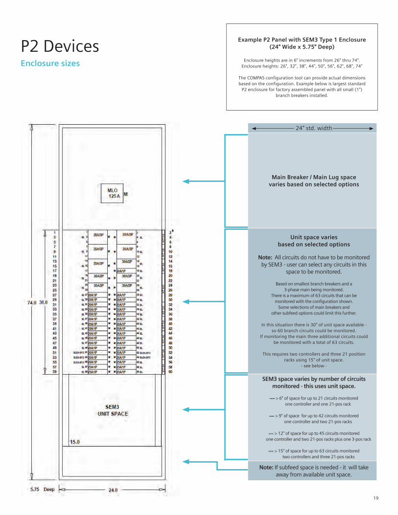
Example P2 Panel with SEM3 Type 1 Enclosure(24" Wide x 5.75" Deep)
Enclosure heights are in 6" increments from 26" thru 74".Enclosure heights: 26", 32", 38", 44", 50", 56", 62", 68", 74"
The COMPAS configuration tool can provide actual dimensionsbased on the configuration. Example below is largest standard
P2 enclosure for factory assembled panel with all small (1")branch breakers installed.
24" std. width
Main Breaker / Main Lug spacevaries based on selected options
Unit space variesbased on selected options
Note: All circuits do not have to be monitored by SEM3 - user can select any circuits in this
space to be monitored.
Based on smallest branch breakers and a3-phase main being monitored.
There is a maximum of 63 circuits that can bemonitored with the configuration shown.
Some selections of main breakers and other subfeed options could limit this further.
In this situation there is 30" of unit space available -so 60 branch circuits could be monitored.
If monitoring the main three additional circuits couldbe monitored with a total of 63 circuits.
This requires two controllers and three 21 positionracks using 15" of unit space.
- see below -
SEM3 space varies by number of circuits monitored - this uses unit space.
== > 6" of space for up to 21 circuits monitored one controller and one 21-pos rack
== > 9" of space for up to 42 circuits monitored one controller and two 21-pos racks
== > 12" of space for up to 45 circuits monitored one controller and two 21-pos racks plus one 3-pos rack
== > 15" of space for up to 63 circuits monitored two controllers and three 21-pos racks
Note: If subfeed space is needed - it will take away from available unit space.
19
P2 DevicesEnclosure sizes
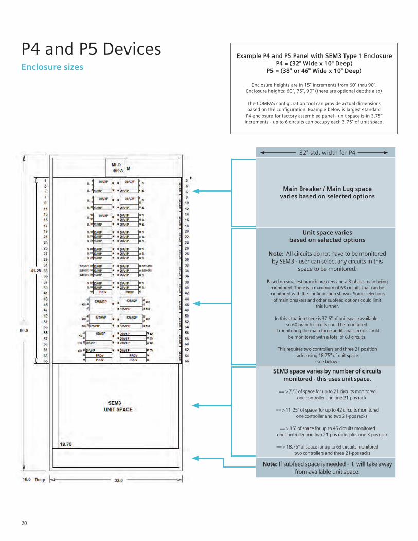
32" std. width for P4
Main Breaker / Main Lug spacevaries based on selected options
Unit space variesbased on selected options
Note: All circuits do not have to be monitored by SEM3 - user can select any circuits in this
space to be monitored.
Based on smallest branch breakers and a 3-phase main being monitored. There is a maximum of 63 circuits that can bemonitored with the configuration shown. Some selections
of main breakers and other subfeed options could limit this further.
In this situation there is 37.5" of unit space available -so 60 branch circuits could be monitored.
If monitoring the main three additional circuits couldbe monitored with a total of 63 circuits.
This requires two controllers and three 21 positionracks using 18.75" of unit space.
- see below -
SEM3 space varies by number of circuits monitored - this uses unit space.
== > 7.5" of space for up to 21 circuits monitored one controller and one 21-pos rack
== > 11.25" of space for up to 42 circuits monitored one controller and two 21-pos racks
== > 15" of space for up to 45 circuits monitored one controller and two 21-pos racks plus one 3-pos rack
== > 18.75" of space for up to 63 circuits monitored two controllers and three 21-pos racks
Note: If subfeed space is needed - it will take away from available unit space.
Example P4 and P5 Panel with SEM3 Type 1 Enclosure P4 = (32" Wide x 10" Deep)
P5 = (38" or 46" Wide x 10" Deep)
Enclosure heights are in 15" increments from 60" thru 90".Enclosure heights: 60", 75", 90" (there are optional depths also)
The COMPAS configuration tool can provide actual dimensionsbased on the configuration. Example below is largest standard
P4 enclosure for factory assembled panel - unit space is in 3.75"increments - up to 6 circuits can occupy each 3.75" of unit space.
20
P4 and P5 DevicesEnclosure sizes
Ordering Information
21
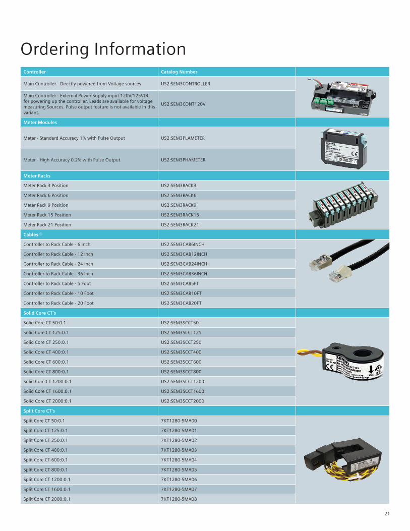
Controller Catalog Number
Main Controller - Directly powered from Voltage sources US2:SEM3CONTROLLER
Main Controller - External Power Supply input 120V/125VDC for powering up the controller. Leads are available for voltage measuring Sources. Pulse output feature is not available in this variant.
US2:SEM3CONT120V
Meter Modules
Meter - Standard Accuracy 1% with Pulse Output US2:SEM3PLAMETER
Meter - High Accuracy 0.2% with Pulse Output US2:SEM3PHAMETER
Meter Racks
Meter Rack 3 Position US2:SEM3RACK3
Meter Rack 6 Position US2:SEM3RACK6
Meter Rack 9 Position US2:SEM3RACK9
Meter Rack 15 Position US2:SEM3RACK15
Meter Rack 21 Position US2:SEM3RACK21
Cables a
Controller to Rack Cable - 6 Inch US2:SEM3CAB6INCH
Controller to Rack Cable - 12 Inch US2:SEM3CAB12INCH
Controller to Rack Cable - 24 Inch US2:SEM3CAB24INCH
Controller to Rack Cable - 36 Inch US2:SEM3CAB36INCH
Controller to Rack Cable - 5 Foot US2:SEM3CAB5FT
Controller to Rack Cable - 10 Foot US2:SEM3CAB10FT
Controller to Rack Cable - 20 Foot US2:SEM3CAB20FT
Solid Core CT’s
Solid Core CT 50:0.1 US2:SEM3SCCT50
Solid Core CT 125:0.1 US2:SEM3SCCT125
Solid Core CT 250:0.1 US2:SEM3SCCT250
Solid Core CT 400:0.1 US2:SEM3SCCT400
Solid Core CT 600:0.1 US2:SEM3SCCT600
Solid Core CT 800:0.1 US2:SEM3SCCT800
Solid Core CT 1200:0.1 US2:SEM3SCCT1200
Solid Core CT 1600:0.1 US2:SEM3SCCT1600
Solid Core CT 2000:0.1 US2:SEM3SCCT2000
Split Core CT’s
Split Core CT 50:0.1 7KT1280-5MA00
Split Core CT 125:0.1 7KT1280-5MA01
Split Core CT 250:0.1 7KT1280-5MA02
Split Core CT 400:0.1 7KT1280-5MA03
Split Core CT 600:0.1 7KT1280-5MA04
Split Core CT 800:0.1 7KT1280-5MA05
Split Core CT 1200:0.1 7KT1280-5MA06
Split Core CT 1600:0.1 7KT1280-5MA07
Split Core CT 2000:0.1 7KT1280-5MA08

Notes
22

Notes
23

Published by Siemens 2021
Siemens Industry, Inc. 3617 Parkway Ln Peachtree Corners, GA 30092 Siemens Technical Support: 1-800-333-7421 [email protected] Printed in USA-CP Order No. PDSA-SEM3G-0421 All Rights Reserved © 2021, Siemens Industry, Inc. usa.siemens.com/SEM3
The technical data presented in this document is based on an actual case or on as-designed parameters, and therefore should not be relied upon for any specific application and does not constitute a performance guarantee for any projects. Actual results are dependent on variable conditions. Accordingly, Siemens does not make representations, warranties, or assurances as to the accuracy, currency or completeness of the content contained herein. If requested, we will provide specific technical data or specifications with respect to any customer’s particular applications. Our company is constantly involved in engineering and development. For that reason, we reserve the right to modify, at any time, the technology and product specifications contained herein.