Embed Size (px)
Citation preview
Iranian Journal of Electrical & Electronic Engineering, Vol. 5, No. 2, Jun. 2009 143
Sensorless Speed Control of Switched Reluctance Motor Drive
Using the Binary Observer with Online Flux-Linkage
Estimation
S. Sedghizadeh*, C. Lucas** and H. Ghafoori Fard***
Abstract: An adaptive online flux-linkage estimation method for the sensorless control of
switched reluctance motor (SRM) drive is presented in this paper. Sensorless operation is
achieved through a binary observer based algorithm. In order to avoid using the look up
tables of motor characteristics, which makes the system, depends on motor parameters, an
adaptive identification algorithm is used to estimate of the nonlinear flux-linkage
parameters. This method makes position and speed estimation more accurate and robust
towards any model uncertainty, also it is suitable replacement for a priori knowledge of
motor characteristics.
Keywords: Sensorless control, Switched reluctance motor (SRM), Binary observer,
Adaptive identification.
1 Introduction 1
Switched reluctance motors (SRMs) have been the focus
of many researches over the past decades. The simple
mechanical construction is one of the main attractive
features because it has no windings or permanent
magnets on the rotor so its manufacturing cost appears
to be lower compared to other motor types. Also it has
the advantages of simple structure, low cost and high
efficiency. However, the rotor position sensing
requirement is a disadvantage for SRM. Using the
position sensors occupy extra space and add to the total
cost of drive, they also reduce the reliability of the
drive. So replacing such sensors by suitable estimation
methods seems better. A large number of papers of
sensorless control methods have been published in the
last decade, and all of the indirect rotor position sensing
methods is based on measurements of the periodically
varying phase inductance or phase flux [1].
In this paper an online estimation of flux linkage
characteristics method is proposed to achieve sensorless
velocity control of the SRM. In this method actual flux
Iranian Journal of Electrical & Electronic Engineering, 2009.
Paper first received 28 Dec. 2008 and in revised form 22 Apr. 2009.
* The Author is with the Control Group, Electrical Engineering
Department, K.N. Toosi University of Technology, Tehran, IRAN.
E-mail: [email protected].
** The Author is with the Center of Excellence for Control and
Intelligent Processing, University of Tehran, IRAN.
E-mail: [email protected]
*** The Author is with the Electrical Engineering Department,
AmirKabir University of Technology, Tehran, IRAN.
E-mail: [email protected]
linkage can be computed directly from terminal
measurements: voltage and current of the phases and
estimated flux linkage is obtained by the adaptive
estimating algorithm. Actual and estimated flux linkages
are used by a binary observer to estimate the velocity
and rotor position. We must notice that all these
processes are done online. The algorithm is tested on
simulation of a real 6/4 motor that we manufactured and
the relevant test results are presented. Although we did
not actually construct the electronic drive to implement
the proposed method experimentally as well, the
validity of the simulation models for the electromotor
under consideration has been extensively studied via
both FE calculations and laboratory experimentation as
reported in [24, 25] and its references. The method is
suitable for velocity control applications, such as drill
machines, washing machines and banknote counting
machines.
The paper is organized as follows:
Section 2 is a short review of the existing sensorless
methods. Section 3 introduces the dynamic model of
SRM and system differential equations. Section 4
proposes an online flux-linkage estimation method.
Section 5 represents the binary observer. Section 6
represents the complete block diagram of the system.
Section 7 tests the proposed method by simulation on a
6/4 SRM and reports the most important results. Section
8 concludes the paper.
Iranian Journal of Electrical & Electronic Engineering, Vol. 5, No. 2, Jun. 2009 144
2 A Short Review of Existing Sensorless Methods
Several indirect position sensing methods have been
suggested and published for sensorless control of SRM
drives. They can be divided into two groups,
1. Non-intrusive methods, where position information
is obtained from terminal measurements of voltages
and currents and associated computation. These
methods rely on the machine characteristics for
estimating the rotor position and the terminal
measurements of phase voltage or mutual voltage and
current are used as inputs for an estimator to obtain
the rotor position. The wave form detection
techniques [2], model-based or observer-based
estimator techniques [3]-[7], the flux-current method
[8] and the mutual voltage method [9, 10] are
examples of methods that fall under this category.
Observer based methods and flux-current methods are
examples of schemes that could be used for high
resolution position sensing. These methods are also
suitable for position sensing at high speeds, but high
speed computational requirements tend to increase the
cost of these types of indirect sensors even more.
2. Intrusive methods, where low level, high
frequency signals are injected into an idle phase to
determine the position dependent, unsaturated phase
inductance characteristics. Methods based on
monitoring current waveforms or passive waveform
detection [11, 12], modulation based techniques [13]
and flux sensing techniques [14] are examples of
methods belonging to this family. The simplicity of
these methods is a define advantage, although
inherent speed limitation and generation of negative
torque in the sensing phases could be a drawback in
some cases.
3 System Differential Equation and Dynamic Model
of SRM
The dynamic characteristics of SRM consist of its
electromagnetic, torque and mechanical equations. By
neglecting the mutual effect of the phases, the voltage
applied to one phase of SRM can be expressed as
follows:
n,1,j,dt
dλiRv
j
jjL=+⋅= (1)
where,
:vj
Voltage of the phase j
:ij
Current of the phase j
:R Phase winding resistance
:λj
Flux linkage of the phase j
:n Number of phases.
In the SRM, flux is a function of both the current
and the rotor position,
dt
dθ
θ
λ
dt
di
i
λ
dt
dλ j
j
jj
j
jj⋅
∂
∂+⋅
∂
∂= (2)
where,
:θ Rotor position
So the phase current can be expressed as follows,
⋅
∂
∂−⋅−⋅
∂
∂=
−
dt
dθ
θ
λiRv
i
λ
dt
dij
j
j
jjj
1
j
jj (3)
When each phase of the SRM is exited, it produces
an instantaneous torque. The instantaneous torque of
each phase can be shown as below:
diθ
)θ,(iλΤ
ji
0j
jjj
j⋅∫
∂
∂= (4)
and the total torque of the motor can be found by adding
the instantaneous torques of the phases, as follow,
( )∑==
n
1jjjjmθ,iΤΤ (5)
Mechanical equations can be expressed as below:
ωBdt
dωJΤΤ
Lm⋅+⋅=− (6)
where,
:ΤL
Load torque
:ω Rotor speed
:J Moment of inertia
:B Coefficient of friction.
When equation (6) is re-arranged in order to write
the speed we found the following equation:
( )ωBΤΤJ
1
dt
dωLm
⋅−−= (7)
In this equations the phase flux linkagejλ , the rotor
position θ and the rotor speed ω constitute the state
variables.
We must notice that, in this modeling λ and mΤ are
the nonlinear parameters and usually they are derived
using flux-current-angle ( )θiλ −− and torque-current-
angle ( )θiΤ −− characteristics data, obtained by finite
element analysis [15] or by some approximation
modeling techniques, such as adaptive identification
methods [16]-[17] and neural networks based or fuzzy
logic based methods [18]-[22]. The flux linkage
characteristic of the 6/4 SRM that we manufactured has
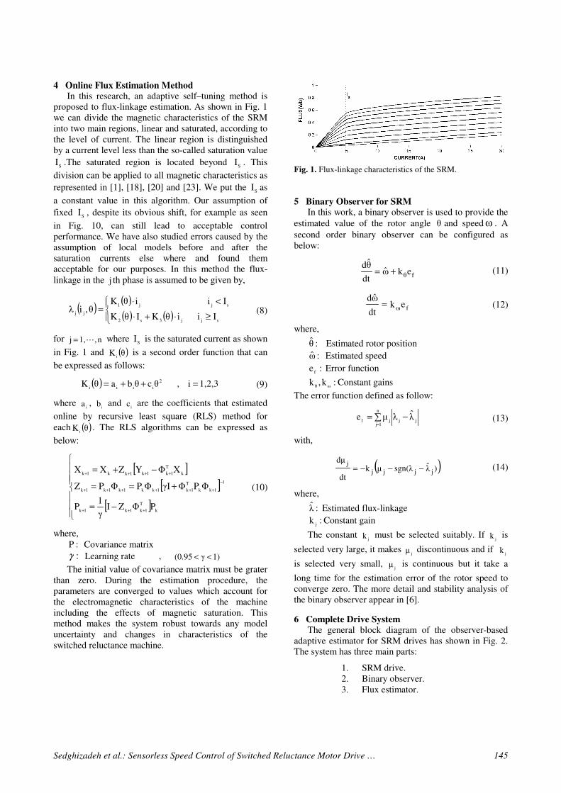
shown in Fig. 1. As shown in Fig.1 the flux linkage
characteristic is nonlinear because the lines are not the
equidistance in different angles.
Sedghizadeh et al.: Sensorless Speed Control of Switched Reluctance Motor Drive … 145
4 Online Flux Estimation Method
In this research, an adaptive self–tuning method is
proposed to flux-linkage estimation. As shown in Fig. 1
we can divide the magnetic characteristics of the SRM
into two main regions, linear and saturated, according to
the level of current. The linear region is distinguished
by a current level less than the so-called saturation value
SI .The saturated region is located beyond
SI . This
division can be applied to all magnetic characteristics as
represented in [1], [18], [20] and [23]. We put the S
I as
a constant value in this algorithm. Our assumption of
fixed S
I , despite its obvious shift, for example as seen
in Fig. 10, can still lead to acceptable control
performance. We have also studied errors caused by the
assumption of local models before and after the
saturation currents else where and found them
acceptable for our purposes. In this method the flux-
linkage in the j th phase is assumed to be given by,
( )( )( ) ( )
≥⋅+⋅
<⋅=
sjj3s2
sjj1
jjIiiθKIθK
IiiθKθ,iλ (8)
for n,1,j L= where S
I is the saturated current as shown
in Fig. 1 and ( )θKi
is a second order function that can
be expressed as follows:
( ) 1,2,3i,θcθbaθK 2
iiii=++= (9)
where i
a , i
b and i
c are the coefficients that estimated
online by recursive least square (RLS) method for
each ( )θKi
. The RLS algorithms can be expressed as
below:
[ ][ ]
[ ]
−=
+==
−+=
+++
−
++++++
++++
k
T
1k1k1k
1
1kk
T
1k1kk1k1k1k
k
T
1k1k1kk1k
PΦZIγ
1P
ΦPΦγIΦPΦPZ
XΦYZXX
(10)
where,
:P Covariance matrix
:γ Learning rate , 1)γ(0.95 <<
The initial value of covariance matrix must be grater
than zero. During the estimation procedure, the
parameters are converged to values which account for
the electromagnetic characteristics of the machine
including the effects of magnetic saturation. This
method makes the system robust towards any model
uncertainty and changes in characteristics of the
switched reluctance machine.
Fig. 1.. Flux-linkage characteristics of the SRM.
5 Binary Observer for SRM
In this work, a binary observer is used to provide the
estimated value of the rotor angle θ and speedω . A
second order binary observer can be configured as
below:
fθekω̂dt
θ̂d+=
fωekdt
ω̂d=
(11)
(12)
where,
:θ̂ Estimated rotor position
:ω̂ Estimated speed
:ef
Error function
:k,kωθ
Constant gains
The error function defined as follow:
∑ −==
n
1jjjjfλ̂λµe (13)
with,
( ))λ̂sgn(λµkdt
dµ
jjjj
j−−−= (14)
where,
:λ̂ Estimated flux-linkage
:kj
Constant gain
The constant j
k must be selected suitably. If j
k is
selected very large, it makes jµ discontinuous and if
jk
is selected very small, jµ is continuous but it take a
long time for the estimation error of the rotor speed to
converge zero. The more detail and stability analysis of
the binary observer appear in [6].
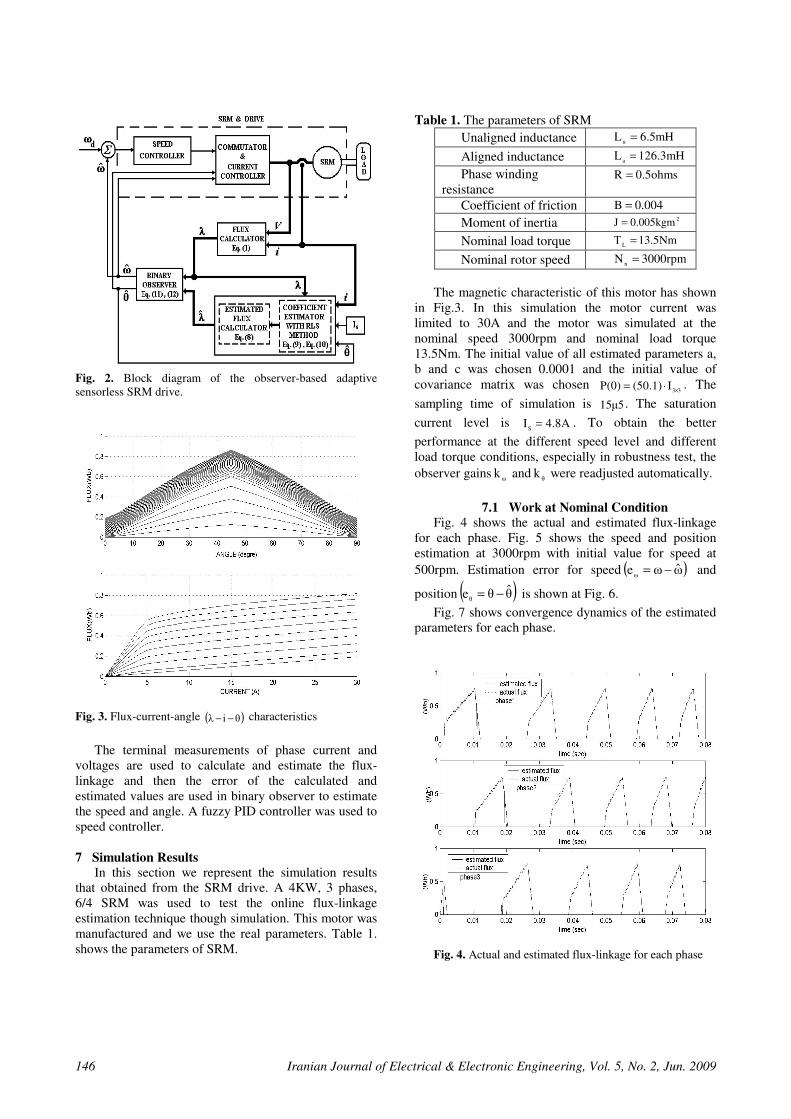
6 Complete Drive System
The general block diagram of the observer-based
adaptive estimator for SRM drives has shown in Fig. 2.
The system has three main parts:
1. SRM drive.
2. Binary observer.
3. Flux estimator.
Iranian Journal of Electrical & Electronic Engineering, Vol. 5, No. 2, Jun. 2009 146
Fig. 2.. Block diagram of the observer-based adaptive
sensorless SRM drive.
Fig. 3. Flux-current-angle ( )θiλ −− characteristics
The terminal measurements of phase current and
voltages are used to calculate and estimate the flux-
linkage and then the error of the calculated and
estimated values are used in binary observer to estimate
the speed and angle. A fuzzy PID controller was used to
speed controller.
7 Simulation Results
In this section we represent the simulation results
that obtained from the SRM drive. A 4KW, 3 phases,
6/4 SRM was used to test the online flux-linkage
estimation technique though simulation. This motor was
manufactured and we use the real parameters. Table 1.
shows the parameters of SRM.
Table 1. The parameters of SRM
Unaligned inductance 6.5mHLu
=
Aligned inductance 126.3mHLa
=
Phase winding
resistance 0.5ohmsR =
Coefficient of friction 0.004B =
Moment of inertia 20.005kgmJ =
Nominal load torque 13.5NmΤL
=
Nominal rotor speed 3000rpmNn
=
The magnetic characteristic of this motor has shown
in Fig.3. In this simulation the motor current was
limited to 30A and the motor was simulated at the
nominal speed 3000rpm and nominal load torque
13.5Nm. The initial value of all estimated parameters a,
b and c was chosen 0.0001 and the initial value of
covariance matrix was chosen 33
I(50.1)P(0) ×⋅= . The
sampling time of simulation is 15µ5 . The saturation
current level is 4.8AIS
= . To obtain the better
performance at the different speed level and different
load torque conditions, especially in robustness test, the
observer gainsω
k andθ
k were readjusted automatically.
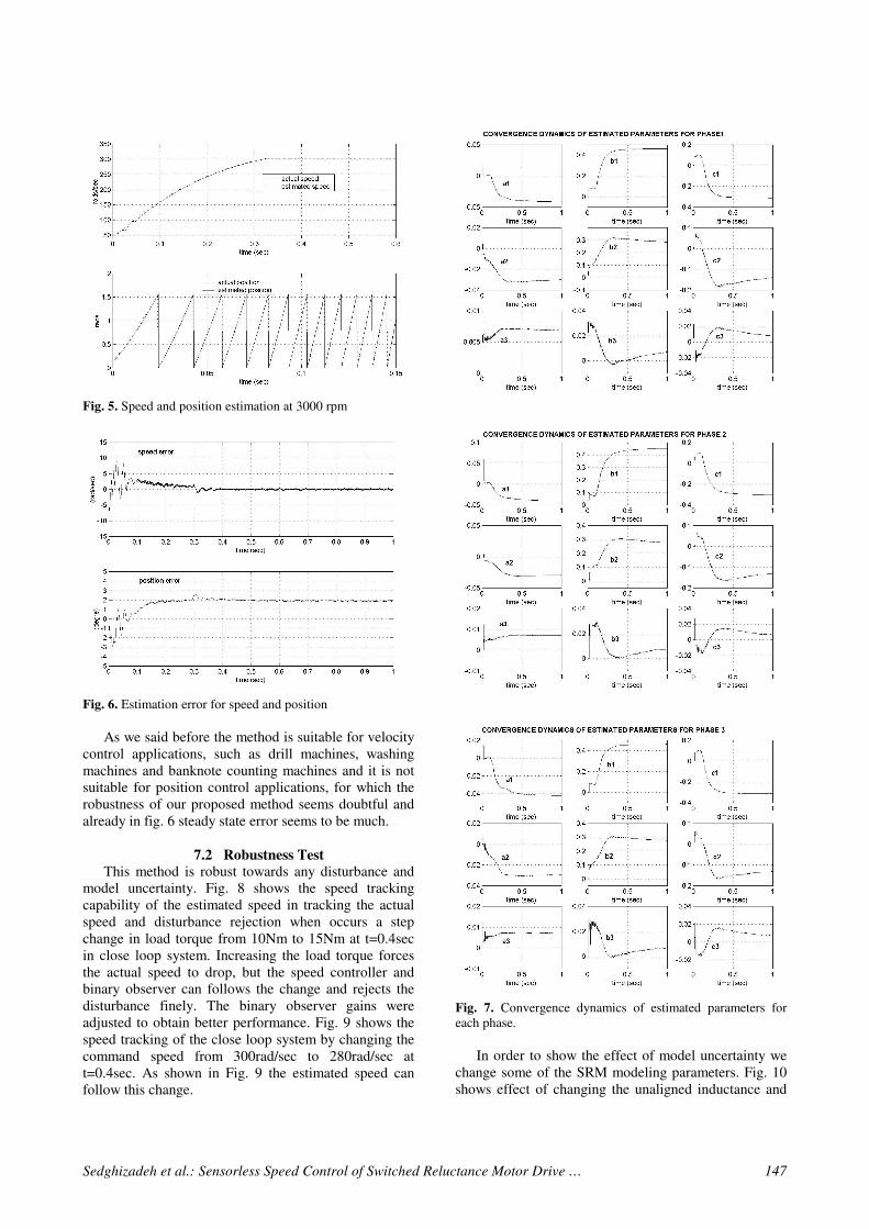
7.1 Work at Nominal Condition
Fig. 4 shows the actual and estimated flux-linkage
for each phase. Fig. 5 shows the speed and position
estimation at 3000rpm with initial value for speed at
500rpm. Estimation error for speed ( )ω̂ωeω
−= and
position ( )θ̂θeθ
−= is shown at Fig. 6.
Fig. 7 shows convergence dynamics of the estimated
parameters for each phase.
Fig. 4. Actual and estimated flux-linkage for each phase
Sedghizadeh et al.: Sensorless Speed Control of Switched Reluctance Motor Drive … 147
Fig. 5. Speed and position estimation at 3000 rpm
Fig. 6. Estimation error for speed and position
As we said before the method is suitable for velocity
control applications, such as drill machines, washing
machines and banknote counting machines and it is not
suitable for position control applications, for which the
robustness of our proposed method seems doubtful and
already in fig. 6 steady state error seems to be much.
7.2 Robustness Test
This method is robust towards any disturbance and
model uncertainty. Fig. 8 shows the speed tracking
capability of the estimated speed in tracking the actual
speed and disturbance rejection when occurs a step
change in load torque from 10Nm to 15Nm at t=0.4sec
in close loop system. Increasing the load torque forces
the actual speed to drop, but the speed controller and
binary observer can follows the change and rejects the
disturbance finely. The binary observer gains were
adjusted to obtain better performance. Fig. 9 shows the
speed tracking of the close loop system by changing the
command speed from 300rad/sec to 280rad/sec at
t=0.4sec. As shown in Fig. 9 the estimated speed can
follow this change.
Fig. 7. Convergence dynamics of estimated parameters for
each phase.
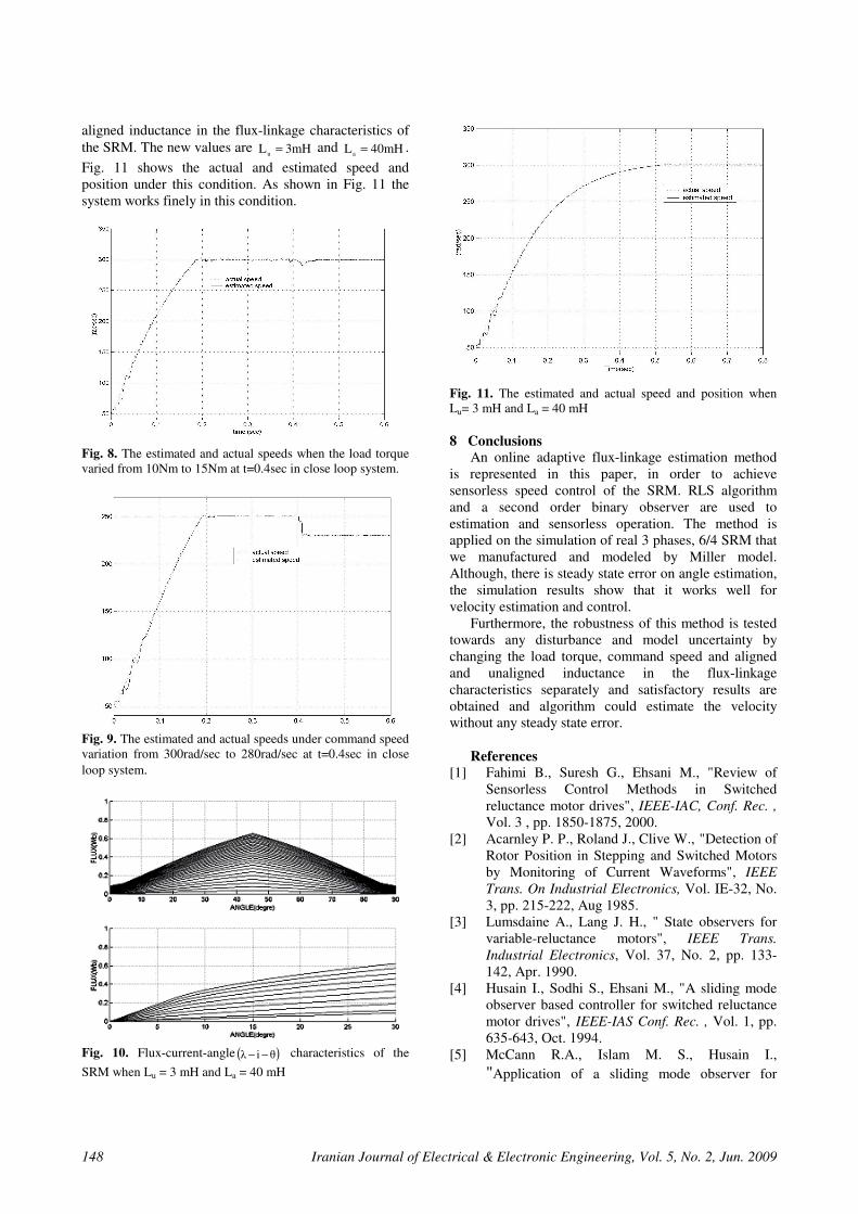
In order to show the effect of model uncertainty we
change some of the SRM modeling parameters. Fig. 10
shows effect of changing the unaligned inductance and
Iranian Journal of Electrical & Electronic Engineering, Vol. 5, No. 2, Jun. 2009 148
aligned inductance in the flux-linkage characteristics of
the SRM. The new values are 3mHLu
= and 40mHLa
= .
Fig. 11 shows the actual and estimated speed and
position under this condition. As shown in Fig. 11 the
system works finely in this condition.
Fig. 8. The estimated and actual speeds when the load torque
varied from 10Nm to 15Nm at t=0.4sec in close loop system.
Fig. 9. The estimated and actual speeds under command speed
variation from 300rad/sec to 280rad/sec at t=0.4sec in close
loop system.
Fig. 10. Flux-current-angle ( )θiλ −− characteristics of the
SRM when Lu = 3 mH and La = 40 mH
Fig. 11. The estimated and actual speed and position when
Lu= 3 mH and La = 40 mH
8 Conclusions
An online adaptive flux-linkage estimation method
is represented in this paper, in order to achieve
sensorless speed control of the SRM. RLS algorithm
and a second order binary observer are used to
estimation and sensorless operation. The method is
applied on the simulation of real 3 phases, 6/4 SRM that
we manufactured and modeled by Miller model.
Although, there is steady state error on angle estimation,
the simulation results show that it works well for
velocity estimation and control.
Furthermore, the robustness of this method is tested
towards any disturbance and model uncertainty by
changing the load torque, command speed and aligned
and unaligned inductance in the flux-linkage
characteristics separately and satisfactory results are
obtained and algorithm could estimate the velocity
without any steady state error.
References
[1] Fahimi B., Suresh G., Ehsani M., "Review of
Sensorless Control Methods in Switched
reluctance motor drives", IEEE-IAC, Conf. Rec. ,
Vol. 3 , pp. 1850-1875, 2000..
[2] Acarnley P. P., Roland J., Clive W., "Detection of
Rotor Position in Stepping and Switched Motors
by Monitoring of Current Waveforms", IEEE
Trans. On Industrial Electronics, Vol. IE-32, No.
3, pp. 215-222, Aug 1985..
[3] Lumsdaine A., Lang J. H., " State observers for
variable-reluctance motors", IEEE Trans.
Industrial Electronics, Vol. 37, No. 2, pp. 133-
142, Apr.. 1990..
[4] Husain I., Sodhi S., Ehsani M., "A sliding mode
observer based controller for switched reluctance
motor drives", IEEE-IAS Conf. Rec. , Vol. 1, pp.
635-643, Oct.. 1994..
[5] McCann R.A., Islam M. S., Husain I.,
"Application of a sliding mode observer for
Sedghizadeh et al.: Sensorless Speed Control of Switched Reluctance Motor Drive … 149
position and speed estimation in switched
reluctance motor drives", IEEE Trans. On
Industry Applications, Vol. 37, No. 1, pp. 51-58,
Jan/Feb 2001..
[6] Yang I. W., Kim Y. S., Lee Y. G., "The rotor
speed and position sensorless control of SRM
using the binary observer", IEEE-IAS, Conf. Rec.,
Vol. 1, pp. 533-538, 1999.
[7] Yang I.W., Shin J.W., Kim Y.S., "The rotor speed
and position sensorless control of switched
reluctance motor using the adaptive observer",
IEEE-TENCOON 99 Conf., Vol. 2, pp. 1450-
1453, Dec..1999..
[8] Lyons J. P., MacMinn S.R. , Preston M.A. ,
"Flux-current methods for SRM rotor position
estimation", IEEE-IAS Conf. Rec., Vol. 1, pp.
482-487, Oct..1991..
[9] Husain I., Ehsani M., "Rotor position sensing in
switched reluctance motor drives by measuring
mutually induced voltages", IEEE Trans. On
Industry Applications, Vol. 30, No. 3, pp. 665-
672, May/Jun..1994..
[10] Chi, H.P., Liang, T.J., Chu, C.L., Chen, J.F.,
Chang, M.T., "Improved mutual voltage
technique of indirect rotor position sensing in
switched reluctance motor", IEEE Power
Electronics Spec. Conf., Vol. 1, pp. 271-275,
2002..
[11] Panda S.K., Amaratunga G., "Waveform
detection techniques for indirect rotor position
sensing of switched reluctance motor drives, Part
I Analysis and Part II Experimental Results", IEE
Proceedings, Vol. 140, No. 1, pp. 80-96, Jan..
1993..
[12] Panda S.K., Amaratunga G., "Comparison of two
techniques for closed loop drive of VR step
motors without direct rotor position sensing",
IEEE Trans. Industrial Electronics, Vol. 38, No.
2, pp. 95-101, Apr.. 1991..
[13] Ehsani M., Husain I., Mahajan S., Ramani K.R.,
"New modulation techniques for rotor position
sensing in switched reluctance motors" , IEEE
Trans. on Industry Applications, Vol. 30, No. 1,
pp. 85-91, Jan/Feb.. 1994..
[14] Mvungi N.H., Lahoud M.A., Stephenson J.M., "A
new sensorless position detector for SR drives" ,
Power Electronics and Variable Speed Drives,
pp. 249-252, Jul. 1990..
[15] Parreira B., Rafael S., Pires A.J., Branco P.J.C.,
"Obtaining the magnetic characteristics of an 8/6
switched reluctance machine: from FEM analysis
to the experimental tests", IEEE Trans. on
Industrial Electronics, Vol. 52, No. 6, pp. 1635-
1643, Dec.. 2005..
[16] Islam M.S., Husain I, "Self-tuning of sensorless
switched reluctance motor drives with online
parameter identification", IEEE-IAS Conf. Rec.,
Vol. 3, pp. 1738-1744, 2000.
[17] Husain I., Hossain S.A., "Modeling, simulation,
and control of switched reluctance motor drives",
IEEE Trans. on Industrial Electronics, Vol. 52,
No. 6, pp. 1625- 1634, Dec.. 2005..
[18] Cheok A., Ertugrul N., "A model free fuzzy logic
based rotor position sensorless switched
Reluctance motor drive", IEEE-IAS Conf. Rec.,
Vol. 1, pp. 76-83, Oct..1996..
[19] Ertugrul N., Cheok A., "Use of fuzzy logic for
modeling, estimation and prediction in switched
reluctance motor drive", IEEE Trans. On
Industrial Electronics, Vol. 46, No. 6, pp. 1207-
1224, Dec..1999..
[20] Ertugrul N., Cheok A., "High robustness of an SR
motor angle estimation algorithm using fuzzy
predictive filters and heuristic knowledge-based
rules", IEEE Trans. On Industrial Electronics,
Vol. 46, No. 5, pp. 904-916, Oct..1999..
[21] Eyguesier C., Tseng K.J., Yan F., Cao S., "A
basic algorithm of sensorless rotor position
detection using fuzzy logic for the switched
reluctance motor drive", IEEE ISIE'99, Vol. 2, pp.
684-688, 1999..
[22] Lin Z., Reay D.S., Williams B.W., He X., "Online
modeling for switched reluctance motors using B-
Spline neural networks", IEEE Trans. on
Industrial Electronics, Vol. 54, No. 6, pp. 3317-
3322, Dec.. 2007..
[23] Buja G.S., Valla M.I., "Control characteristics of
the SRM drives. Part II: Operation in the
saturated region", IEEE Trans. on Industrial
electronics, Vol. 41, No. 3, pp. 316-325, Jun..1994
..
[24] Farshad M., Faiz J., Lucas C., "Development of
analytical models of switched reluctance motor in
two-phase excitation mode: extended miller
model",IEEE Trans. on Magnetic, Vol. 41, No. 6,
pp. 2145-2155, Jun.. 2005..
[25] Farshad M., Faiz J., Lucas C., Ghafoorifard H.,
"Examination And Modeling Of The Mutual
Coupling Effects Of Phases Windings In SR 6/4
Motor Using Two-Dimensional FE Analysis".
University of Tehran, Journal of Faculty of
Engineering, Vol. 3, No. 38, pp. 381-393, 2004.
Saba Sedghizadeh received her
B.Sc. and M.Sc. from IAU in
Tehran, Iran in 1998 and 2001, both
in Electrical and Control
Engineering. She is currently a
member of Control Department of
K.N. Toosi University of
Technology. Her field of interest
includes Linear Control Systems
and Switched Reluctance Motors Drives Control.
Iranian Journal of Electrical & Electronic Engineering, Vol. 5, No. 2, Jun. 2009 150
Caro Lucas received the M.S. degree
from the University of Tehran,
Tehran, Iran in 1973 and the Ph.D.
degree from the University of
California, Berkeley, in 1976. He is a
Professor, and a member (as well as
the founder-Director) of Center of
Excellence for Control and Intelligent
Processing, Department of Electrical
and Computer Engineering, University of Tehran, as well as a
Researcher at the School of Cognitive Sciences (SCS),
Institute for Studies in Theoretical Physics and Mathematics
(IPM), Tehran, Iran. He has served as the Director of
Intelligent Systems Research Faculty, IPM (1993-1997) and
Chairman of the ECE Department at the University of Tehran
(1986-1988). He was also a Visiting Associate Professor at the
University of Toronto, Toronto, Canada (summer, 1989-
1990), University of California, Berkeley (1988-1989), an
Assistant Professor at Garyounis University (1984-1985),
University of California, Los Angeles (1975-1976), a Senior
Researcher at the International Center for Theoretical Physics,
and the International Center for Genetic Engineering and
Biotechnology, both in Trieste, Italy, the Institute of Applied
Mathematics, Chinese Academy of sciences, Harbin Institute
of Electrical Technology, a Research Associate at the
Manufacturing Research Corporation of Ontario, and a
Research Assistant at the Electronic Research Laboratory,
University of California, Berkeley. His research interests
include biological computing, computational intelligence,
uncertain systems, intelligent control, neural networks, multi
agent systems, data mining, business intelligence, financial
modeling, and knowledge management. He was the founder of
the ISRF, IPM and has assisted in founding several new
research organizations and engineering disciplines in Iran. He
is the holder of the patent for Speaker Independent Farsi
Isolated Word Nero recognizer. Dr. Lucas has served as
Managing Editor of the Memories of the Engineering Faculty,
University of Tehran (1979-1991), Reviewer of Mathematical
Reviewers (since 1987), Associate Editor of the Journal of
Intelligent and Fuzzy Systems (1992-1999), and Chairman of
the IEEE, Iran Section (1990-1992). He has served as the
Chairman of several international conferences.
Hassan Ghafoori Fard received his
B.Sc. from the University of Tehran,
Tehran, Iran in physic in 1965 and
M.Sc. degrees from University of
Japan in seismology in 1969 and
Ph.D. degree from Kansas
University, in nucleonic physic in
1977. He is currently an associate
Professor and a member of Electrical
Engineering Department of
Amirkabir University of Technology
(Tehran Polytechnic). He was the president of IKI University
from 2006 to 2009. His research has focused mainly on
Electronics, Wave and Electromagnetic and Quantum
Mechanics.