Embed Size (px)
Citation preview
Sequential design of decentralised control for FACTS devices in large power systems
M.M. Farsangi, Y.H. Song, X.F. Wang and M. Tan
Abstract: A procedure for sequential design of decentralised FACTS controllers for multiinachine power systems is presented. It is shown how to include a simple estimate of the effects of closing subsequent loops into the design problem for the loop to be closed. The focus of the paper is on the des& performance where frequency-domain methods prove to be very useful. A comprehensive and systematic way of designing decentralised controllers is presented and the results are illustrated using a 16-machine 5-area system. The methodology to select the input signal used for supplementary control of FAITS devices in large power systems is also addressed.
1 Introduction
Poorly damped low-frequency (0.1-2 Hz) interarea oscillations are inherent in interconnected power systems. The phenomenon is very complex as it involves several electromechanical oscillatory subsystems. which often comprise sevcral groups of machines distributed over neighbouring utilities. The nature of the interaction makes the damping-control design task challenging. The design methodology should therefore aim at improving the damping performance of one mode while ensuring the least interaction with other modes. In addition, the controller should guarantee stable operation over the full range of system operating conditions. In this paper the N,-loop-shaping method is used to arrive at a decentralised controller structure, which provides robust stability and performance over a range of nncertain- ties of interest. The sequential design, which involves closing and tuning one loop at a time, is used to design the controller for the unified power-flow controller (UPFC), static synchronous series compcnsator (SSSC) and static VAr compensator (SVC). Ref [ I ] gives details of FACTS devices. These are probably the most common design procedures in real-world applications. However, there are problems associated with sequential design as roiiows [21:
(i) Only one output is usually considered at a time and the closing of subsequent loops may alter the mponse of previously designed loops and thus make iteration necessary. (ii) The final controller design and thus the control quality achieved may depend on the order in which the controller in the individual loops is designed.
iB IEE. 2003 I€€ Proc~&g.s online no. 20030307 dakl0. 1049/ipgld200303(17 Online publishing date: I O February 2003. Papcr first reccivcd 20th November 2001 and in rwised form 13th Seplrmkr 2002 M.M. Famngi and Y.H. Song BR' *ith the Brunel Institute of Powcr Systems. Brunrl University. Uxhridse. Middlx.. UB8 3PH. UK X.F. Wang is w l h Lhc Department of Electical Eneneenng, Xi" Jiaotung Univernty. China M. Tan is with the l n ~ t i t u t ~ of Automalion. Chinese Academy of kiences. China
162
(iii) If G is a square plant with n inputs and 11 outputs, the transfer function between input U, and output y j may contain right-half-plane (RHP) zeros that do not corre- spond to R H P transmission zeros of G.
Thus, the usefulness of a sequcntial design procedure will depend on how successfully it addresses the above issues. The efforts of Djukanovic er U/. [2] have been devoted to the design of a power-system stabiliser (PSS) using the sequential design by applying the papproach without considering the above problems. To take care of the interaction. this paper aims to use the conventional rule, introduced by Hovd and Skogoslad [3], to deal with these problems and presents a design procedure based on obtaining a simple U priori estimates of the final loop shape.
Another issue_ which plays an important role in the ability of controllablc devices to stabilise electromechanical oscillation is finding the location and the selection of input signal. Residue- and damping-torque analyses have been applied by researches [&7] to determine simultaneously the location and the input signal for a single device. However, the methoedoes not consider the controller effect on other eigenvalues. Although residue analysis may he useful for selecting the location and the input signal for a single device. the sequential application of the residue method may not be able to achieve the optimal solution when multiple devices are used to stabilise inultiple critical oscillation modes. This papcr presents a new methodology to select the input signals for the multiple power system damping devices. Based on some early results [8 ] , the paper reports on recent progress on sequential design of decentralised control for FACTS devices in large power systems.
2 Solution to sequential-design problems
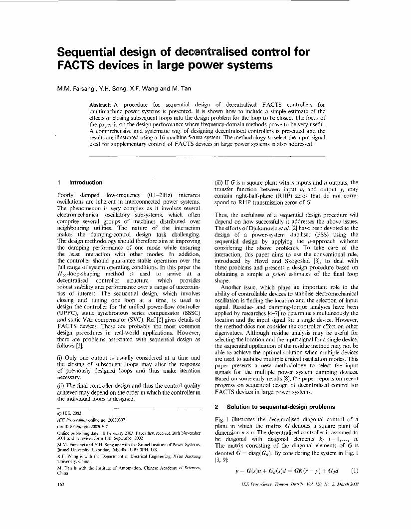
Fig. 1 illustrates the decentralised diagonal control of a plant in which the matrix G denotes a square plant of dimension n x n. The decentralised controller is assumed to be diagonal with diagonal elements k; i = I , , . . , n. The matrix consisting of the diagonal elements of G is denoted G = diag(G,). By considering the system in Fig. I
y = C ( s ) u + Gd(s)d = CK(r ~ y ) + Cdd ( I )
~ 3 ~ 9 1 :
I€€ Proc-Gmcr. Pwmi. Dkrrih.. Vol. 150 No. 2, Mowh 2W3
I - 1
Fig. 1
or
Decenrrulked diuqonul control oJun n x n plunr
y = ( I + C K ) - ' C K r + ( f + G K ) - ' C d d (2) -- 7" S
e = y - I .= -Sr+ SC d in which S is a sensitivity function and T= I-S is the complementary sensitivity function. In Fig. 1 loop i is the SISO input system consisting of C,, and k,. The sensitivity functions and complementary sensitivity functioiis for the individual loops are collected in the diagonal matrices: 3 = diag(.?;) = ( I - and T = diag(?;) = G K ( I - An important relationship for decentralised control is given by the following factorisation of the return different operator:
(3)
( I + G K ) = ( I + E j ' ) ( I + & ) (4) - -- &em// m"ct;,im i,nhc;<h,"i i.Op
in which the matrix E = ( C - G)C-' represents the relative interactions. Equivalentlyl (4) can be written in terms of sensitivity function as
s= S ( f + E ? ) - ' (5)
Equation (5) shows that 3 is not equal to the matrix of diagonal elements of S and that it also depends on the term (I + E?) - ' , which indicates the interaction between different loops. At frequencies where the feedback is effective ? rr f and it can be derived that
( I + E ? ) - L G C - ' = r (6) where r= b<,} is the performance relative-gain array (PRGA), known as an indicator for interaction [3. 91. By substituting (6) into (5) and (3), the following equations can be derived:
s - s r (7)
(8) e = y - Y N - S r r + S r G d d Equations (7) and (8) show that r is important when evaluating performance with decentralised control [IO, 1 I].
To deal with the first problem raised due to interaction, the effect of interaction can be treated as uncertainty in the system. The term ( I +E?) - ' is added to the system as an additive uncertainty (Fig. 2) to express the interaction from the undesigned loops when evaluating performance. This is an estimation of how the undesigned loops will affect the output of the loop to be designed. In Fig. 2, 6 denotes the normalised perturbation and ( I + E?)-'shows the actual perturbation.
To compute the matrix ( I + E?) - ' , an estimation of i, for the undesigned loops is required. A general foim of a complementary sensitivity function is shown in Fig. 3. At frequencies where feedback is effective, IT1 N I and at
I.% Proc.-Cmer. Trmm!. Dhirih.. l'd 150, ,Yo 2. Mrrrch ZW3
4 0 ... 0 G l l o ... o o k2 ;.. o tp j / . . : 0Gz2:.. 0 t. + . . . . : : . . - 0 0 ... kn o o ... Grin
K B
io ' r
1 0 . ~ I
higher frequencies, I TI i 0. Thus, the initial estimates for the complementary sensitivity functions for the individual loops are chosen to be second order of the form ii(s) = 1 /{ (s,";) + I}' ((U, is the bandwidth of the loop) [3], which is a close approximation to the general form of the complementary sensitivity function.
The second and third problems associated with sequential design affect the order of loop closing. Usually the controller corresponding to a fast loop is designed first. If the transfer function between input ui and output J'; contains RHP zeros that do not correspond to RHP zeros of G, the fast loop should be designcd at a later stage.
A procedure for sequential design of a supplementary controller of SVC. SSSC and UPFC is a s rollows:
Step I : Plot PRGA to determine the interaction between different loops. Step 2: Reduce the order of the open-loop plant to ease the controller design. Slep 3: Choose the initial estimates for the complementary sensitivity functions for the individual loops as
Step 4: Add ( I + E?)-' as an additive uncertainty temi and plot the singular values of the open loop. Step 5: Design of controller k, related to loop i by Considering only output JJ; based on the mixed-sensitivity method (the method is explained in [SI). Step 6: Reduce the order of the achieved controller in step 5 . Step 7 Once the controller k, is designed, replace the cstimated 7; in step 3 by the actual one. Step 8: Design of controller k;+ I related to loop i f 1 by considering output yi to J';+ I
t , ( S ) = l/{(s/w;) + I}?.
I63
Step 9: Repeat steps 2 to 7 to design the controller for loop i f 1. Step IO: Design of the last controller is carried 'out by considering the overall system.
Prior to the design of controllers, finding the most responsive stabilising signal is necessary, which is explained in Section 3.
3 Study system and selection of input signal
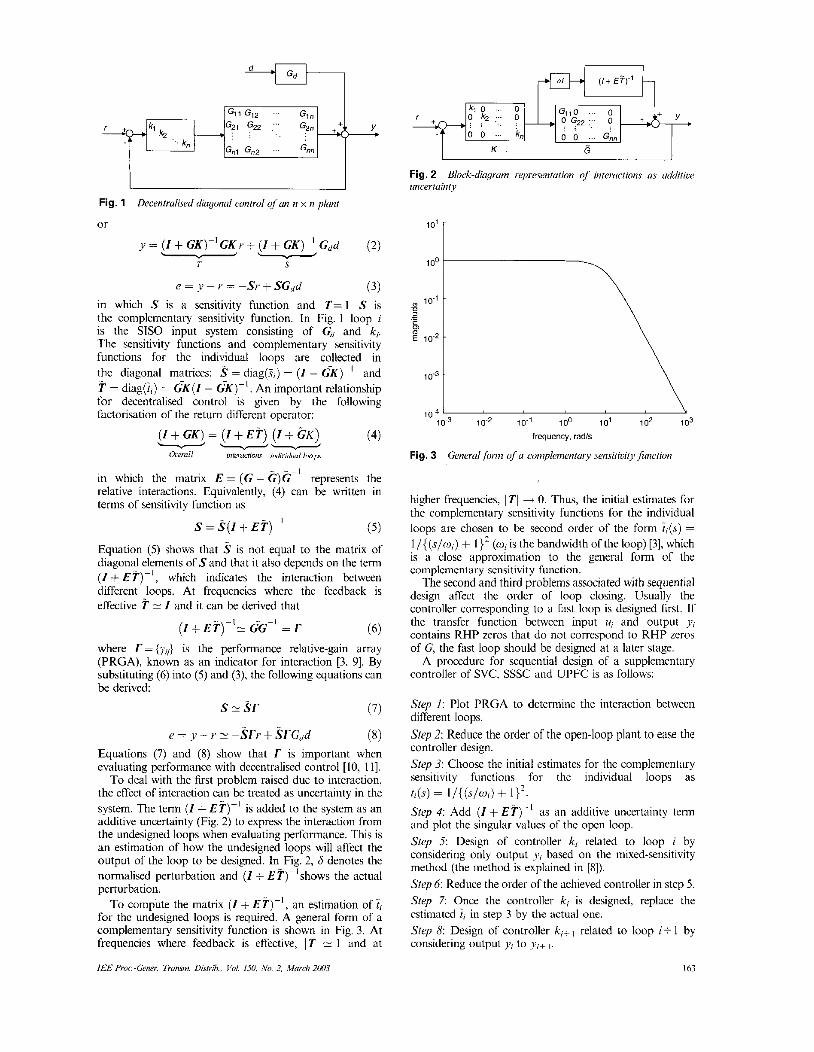
The system shown in Fig. 4 consisting of 16 machines and 68 buses is used. This is a reduced-order model of the New England/New York interconnected system. The first nine machines are a representation of the New England (NE) system generation. Machines I O to 13 represent the New York (NY) power system. The last three machines are the dynamic equivalent of the three large neighbouring areas interconnected to the New York power system [12]. Eigenvalue analysis of the system has been carried out to find the interarea modes. All the interarea modes are not observable in a particular signal nor they all controllable from a single bus location. By more investigation it is found that line 8-9 is a vely weak tieline and buses 7 and S arc very weak buses in the NE system; thus the locations for the UPFC, SSSC and SVC arc considered at 8,8-9; 4&48 and 7, respectively. The models used for FACTS devices can be found in [ 131.
Once the FACTS devices are placed into the power system, the choice for the candidates of input signals of supplementary control of SVC, SSSC and UPFC could be the current magnitude and the active power of line as follows:
SVC: L16-7; 17-8; 19-36; 19-30; p6-7; p7-8; p9-36; p9--301
SSsC: rI4-41; 14-48; p40-41; p4-4X1 UPFC: V - 8 ; 19-36; 19-30: Ps-8; Pg-36; P9-301
To evaluate the alternative Combinations, one may_ based on C, perfonn an input-output controllability analysis for each combination. However, the number of combinations has a combinatorial growth; therefore even a simple input- output colitrollability anilysis becomes very time consum- ing if there are many options. One way of avoiding this combinatorial problem is to base the selection directly on the big models C,a by considering the relative gain array (RGA) of C<,,,. This may be useful for eliminating some options. The remaining candidate combinations can then be analysed more carefully considering minimum singular value, RHP zeros_ taking into account interactions by RGA number and Hankcl singular values [9].
3.1 Steady-state model (SSM) Considering the steady-state model y<,,/= C,,u and the
candidate outputs, the RGA matrix of G, , (with three inputs and 18 candidates of outputs) is a useful screening tool when there are many options. The three row sums of the RGA matrix are calculated and the two largest elements are selected for each device as follows:
SVC : [/6-7; 17-81; SSSC : [ / ~ - 4 1 ; P4-481; UPFC : [/g-y,; &w].
With these candidates, the eight combinations can be achieved as listed in Table I . A more detailed input-output controllability analysis of. the eight candidate output sets is undertaken using minimum singular value.
corresponding RGA matrix, A = CO,/ x C,, t' of the
3.2 Minimum singular value (MSV) The minimum singular value is a particularly useful controllability measure. It should be as large as possible at frequencies where control is needed. In Table I , MSVs are listed for the eight candidate output sets. Among them, the four largest candidates (2, 4, 6 and S) are selected.
G8 60
4 I I - 29 < 28 c
41 V\/ --
61
24 0 G9 27
% G2 54
U G5
G7
Fig
IM
. 4
6 G16 Srructure of the power-s.iarein model
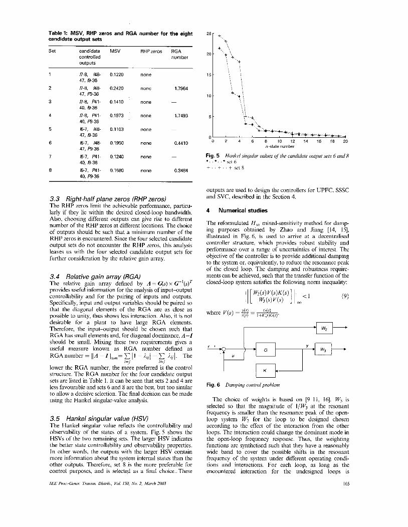
Table 1: MSV, RHP zeros and RGA number for the eight candidate output sets
Set candidate MSV RHPzeros RGA controlled number outputs
1 n-8, 148- 41, 19-36
41, p9-36 2 n-e, IC+
3 U-8, P41- 40. 19-36
4 n-e, ~ 4 1 - 40, p9-36
47. 19-36 5 161, 148-
6 16.1, 148-
1 16-1, P41-
41, p9-36
40, 19-36
40, p9-36 8 167. P41-
0.1220
0.2420
0.1410
0.1913
0.1103
0.1950
0.1240
0.1580
none
none 1.1964
~
none
none 1.7493
~
none
none 0.4410
~
- none
none 0.3484
3.3 Right-half plane zeros (RHP zeros) The RHP zeros limit the achievable performance, particu- larly if they lie within the desired closed-loop bandwidth. Also, choosing different outputs can give rise to different number of the RHP zeros at different locations. The choice of outputs should he such that a minimum number of the RHP zeros is encountered. Since the four selcctcd candidate output sets do not encounter the RHP zeros, this analysis leaves us with the four selected candidate output sets for further consideration by the relative gain array.
3.4 Relative gain array (RGAI The relative gain array defined by A = 4 s ) x G - ' ( s ) ~ provides useful information for thc analysis of input-output controllability and for the pairing of inputs and outputs. Specifically, input and output variables should be paired so that the diagonal elements of the RGA are as close as possible to unity, thus shows less interaction. Also, it is not desirable for a plant to have large RGA elements. Therefore, the input-output should be chosen such that RGA has small elements and, for diagonal dominance. A-f should be small. Mixing these two requirements gives a useful measure known as RGA number defined as RGAnumber= ~ ~ A - I ~ ~ s u m = ~ ~ l ->.ij/+Cliijl. The
lower the RGA number, the more preferred is the control structurc. The RGA number for the four candidate output sets are listed in Table 1. It can be seen that sets 2 and 4 are lcss fivourable and sets 6 and 8 are the best, but too similar to allow a decisive selection. The final decision can be made using the Hankel singular-value analysis.
is=/ . . I=,
3.5 Hankel singular value (HSV) The Hankel singular value reflects the controllability and observability of the states of a system. Fig. 5 shows the HSVs of the two remaining sets. The larger HSV indicates the better state controllability and observability properties. In other words, the outputs with the larger HSV contain more information about the system internal states than the other outputs. Therefore, set 8 is the more preferable for control purposes, and is selected as a final choice.. These
IEE Pr,u:-Gmer. Tmmn Diwib., Vol. 150, No. 2. March 2003
n-state number
Fig. 5 * . . * . . * = t 6 +..+..+se18
Hrmkelsinyular values oftlie candidate oittput .sets 6 und8
outputs are used to design the controllers for UPFC. SSSC and SVC. described in the Section 4.
4 Numerical studies
The reformulated H , mixed-sensitivity method for damp- ing purposes obtained by Zhao and Jiang [14, IS], illustrated in Fig. 6, is used to arrive at a decentralised controller structure, which provides robust stability and performance over a range of uncertainties of interest. The objective of the controller is to provide additional damping to the system or. equivalently, to reduce the resonance peak of the closed loop. The damping and robustness require- ments can he achieved, such that the transfer function of the closed-loop system satisfies the following norm inequality:
Fig. 6 Dampiny mnrml prohlem
The choice of wcights is based on [9-11, 161. W, is selected so that the magnitude of l/W3 at the resonant frcquency is smaller than the resonance peak of the open- loop system W, for the loop to be designed chosen according to the effect of the interaction from the othcr loops. The interaction could change the dominant mode in the open-loop frequency response. Thus, the weighting functions are synthetised such that they have a reasonably wide hand to cover the possible shifts in the resonant frequency of the system under different operating condi- tions and interactions. For each loop, as long as the encountered interaction for the undesigned loops is
165
bounded by W,, the stabilising and the performance of the system is guaranteed.
The procedure explained in Section 2 is used to design a controller for SVC (loop I), SSSC (loop 2) and UPFC (loop 3). First, the PRGA for the study system is plotted (Fig. 7). Since, the current study system has no multivariable RHP zeros and no zeros in the individual elements. from Fig. 7 it can be concluded that the order of loop closing should be: loop 3, loop 2 and loop I . PRGA elemcnts Iargcr than I imply interactions, and this figure shows that there is an interaction from loop I into loops 2 and 3 (G21,G3,) and loop 2 into loop 3 (GZz).
I . s i I 10-1 ‘
10~’ 100 10’ 102 frequency, redis
Fig. 7 Elemenis of PRGA Lines mdsd by squares:
G3 I
- G3z Lines ended by circles:
G2I
~ GI Lines ended by arrow head
Gli ~ GI3
.....
.....
.....
4. I To obtain a simplified estimate of the effects of clcssing of the other loops; an estimate of the complementary sensitivity function for the individual loops is needed. Since the closed-loop feedback should be effective in the r:inge of 0.1-2 Hz (0.612 rad/s) and loop 3 is faster than loops 2 and I , the bandwidth of loop 3 is considered slightly larger than the bandwidth of loop 2 and loop 1 (U?= 10, 02=.8, and fol = 7 radis). Therefore, the initial estimates for the complementary sensitivity function for loops 3, 2 and I are
Controller design for loop 3
I 1
(0.1s + 1)2 (0.125s+ I ) * I
(0.142s + I)’
ids) = i*(s) =
i, (s) =
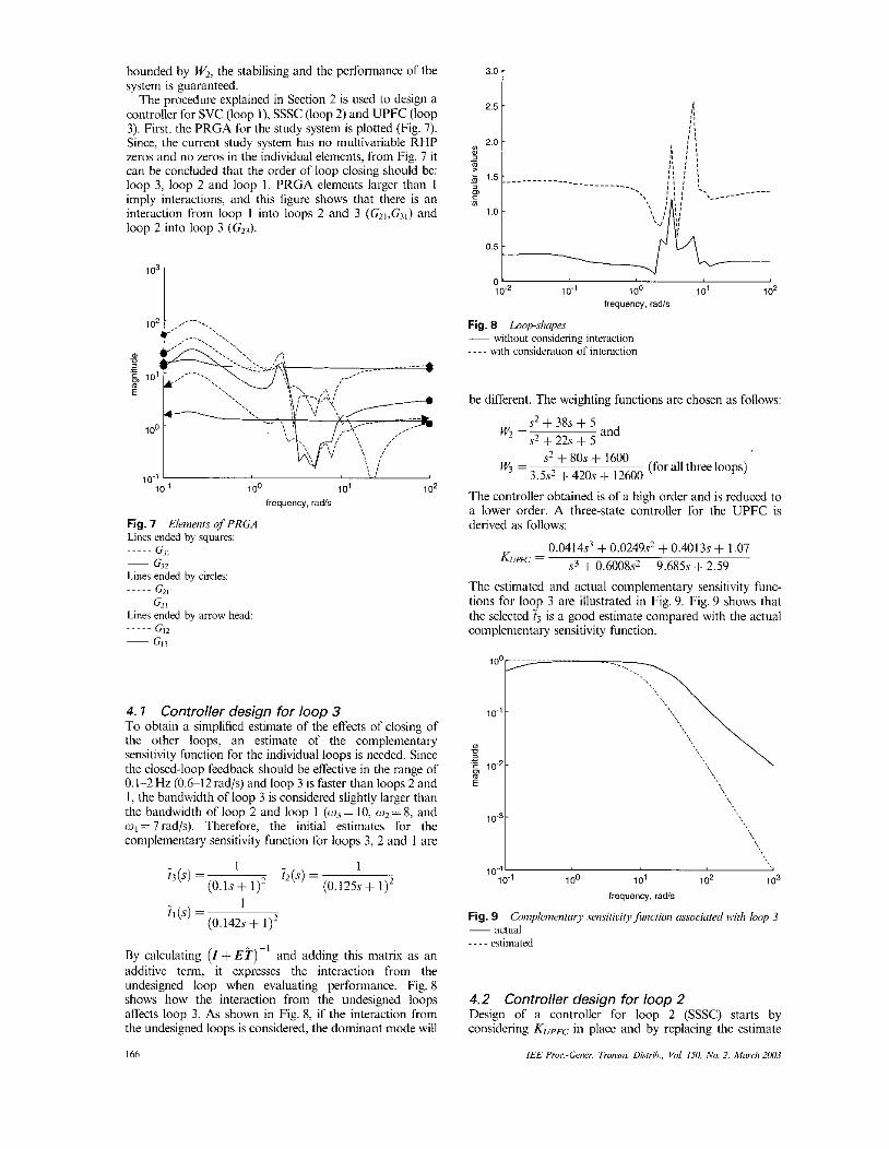
By calculating ( I + E T ) - ’ and adding this matrix as an additive term, it expresses the interaction from the undesigned loop when evaluating performance. Fig. 8 shows how the interaction from the undesigned loops affects loop 3. As shown in Fig. 8, if the interaction from the undesigned loops is considered, the dominant mode will
I66
3’0 i
0‘ 10-2 10-1 100 IO’ 102
frequency, radls
Fig. 8 L.nop-.slupe.s - without considering interaction - - - - with consideration of interdon
be different. The weighting functions are chosen as follows:
s? + 38s + 5 w* = and 5 2 + 22s i 5
s2 + 80s + 1600 3.5s’ + 420s + 12600 w, = (for all three loops)
The controller obtained is of a high order and is reduced to a lower order. A three-statc controller for the UPFC is derived as follows:
0 . 0 4 1 4 ~ ~ + 0.0249s’ + 0.4013s + 1.07 .si + 0.60089 + 9.685s + 2.59 KUPf%. =
The estimated and actual complementary sensitivity func- tions for loop 3 are illustrated in Fig. 9. Fig. 9 shows that the selected i, is a good estimate compared with the actual complementary sensitivity function.
\
104‘ 10-1 1 00 101 102 1 o3
frequency. radh
4.2 Controller design for loop 2 Design of a controller for loop 2 (SSSC) starts by considering KUpFC in phce and by replacing the estimatc
I€€ Pru<:-Gc.rier. Trorr~ni. Dk!r;h., Vi,/. 150. ,No. 2, rifard? 2oU3
1.8 r
frequency. rads
Fig. 10 Loop .slmpe.r ~ without consideration of interaction - - - - with consideration of interaction
0.30 -
0.20 1
0 . 1 5 L ' " ' ' ' ' " ' 0 2 4 6 8 10 12 14 16 18 20
time. s
a
0.50 r
c
1 0 ~ 5 1 10-1 100 101 102 10'
frequency. radk
lime. s
b
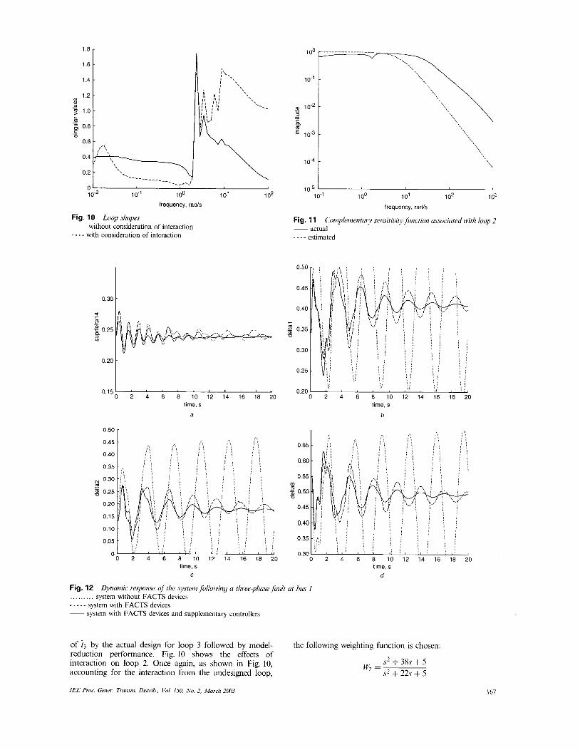
Fig. 12 ... ... ... system without FACTS devices ..... system with FACTS dcvices - system with FACTS devices and supplementary controllers
Dvnainic response offlie .qsfeni folloivify a rh~~~-p l~r i ve f~rc l r (it bus I
time. 5
d
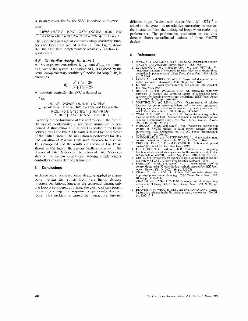
of i3 by the actual design for loop 3 followed by model- reduction performance. Fig. 10 shows the effccts of interaction on loop 2. Once again. as shown in Fig. 10,
the following weighting function is chosen:
s2 + 38s + 5 sz i 22s + 5
wz = accounting for the interaction from the undesigned loop,
IEE A*,r:~Gmer Truum Dhfrrh. Vol. ISU. N o 2 Murdr 2mI3 I67
A six-state controller for the SSSC is derived as follows:
Ksssc
The estimated and actual complementary scnsitivity func- tions for loop 2 are plotted i n Fig. 1 I . This Figure shows that the estimated complementary sensitivity function is a good choice.
4 .3 At this stage, two controllers_ Kul+-c and KsSsc are treated as a part of the system. The estimated i, is replaced by the actual complementary sensitivity function for loop 2. W, is chosen as
Controller design for loop 7
s* + 4s + 20 .+ + 10s + 20
w, =
A nine-state controller the SVC is derived as
Ksic 0.0014.~~ + 0.0085sx + 0.0404~~ + 0 .1644~~
- ~ +0.4215s5 + l.215s4+ 1.46279 +2.95s2 +0.156s+i).016 0.028s9+0. I 13sR+0.886s7+2.59s6+9.73s5 123. 102s~133.8.s1+68.92.s~+3.22.~+0.35
To verify the performance of the controllers in the face of the system nonlinearity, a nonlinear simulation is per- formed. A thrce-phase fault at bus I is coated in the tieline between bus I and bus 2. The fault is cleared by the removal of the faulted circuit. The simulation is performed for 20s. The variation of machine angle with rererence to machine 15 is computed and the results are shown in Fig. 12 As shown in this figure, the system oscillations grow in the absence of FACTS devices. The action of FACTS devices stabilise the system oscillations. Adding supplementary controllers ensures damped behaviour.
5 Conclusions
In this paper, a robust sequential design is applied to ii large power system that suffers from very lightly damped interarea oscillations. Since, in the sequential design, only one loop is considered at a time, the closing of subr,equent loops may change the response of previously designed loops. This problem is caused by interactions between
different loops. To deal with this problem, ( I + E T ) - ' is addcd to the system as an additive uncertainty to cxpress the interaction from the undesigned loops when evaluating pcrfomance. The perfonnance evaluation in the time domain shows co-ordinated actions of three FACTS devices.
6
I
7 -
3
4
5
6
7
X
9
10
II
I ?
13
14
15
16
References
SONG. Y.H.. and JOHNS. A.T.: 'Flexiblc AC transmission svstems (CACTS)', IEE Nwrr mmd Eneqy Swic.i 10 (IEE. 1999) DJUKANOVIC, M.. KHAMMASH. M.. and VIITAL. V.: 'Srqomtiiil synlhcsis of slructurcd singular value hasd decentralized controlln.~ in power systans'. /EEL 7 i m . s . Pmrar Sysr.. 1999. 14. (2).
'
pp. 6 3 5 4 1 HOVD. M.. and SKOCOSLAD. S.: 'Scqucnlial desien of decen- tralised corilioller', Aiiioiiimico. 1994. 30. p i . 1601-160i KUNDUR. P.: 'Powcr systcm slabilily and controf (McCraw-Hill Inc. New York 1994) ROUCO. L.. and ' PAGOLA, F.L.: 'A" eigcnvaluc Sensitivity approach 10 l~cation and controllei design of controllablc sencs capacitors for damping power system osillatioiis'. IEEE T" P o w r SJX. 1997. 12, (4). pp. 1660-1666 MARTINS. N., and LIMA, L.T.G.: 'Detcmination of suitablc locations for power system stabilisers and static Y B T comwnsator
lo~atiun of PSSE or PACTS-based stabili\ers in multimachine power systems: B comp;iralire study'. I.% /'roc., Grnrr. Twwiz. Dnirib.. 1997. 144. (2). pp. 155-159 FARSANGI. M.M.. and SONG, Y.H.: 'Sequential decentralised control of FACTS devices in large power systems'. Seventh Intcmatianiil IEE Confcicnce on AC-DC Power Transmission. London. 2001. pp. 268-273 SKOGOSLAD. S.. and POSTETHWAITE, I.: 'Multivanable input control: antilysis and design' (John Wiley. New York 1996) ZHOU. K.. DOLE, J. C.. and CLOVER. K.: 'Robust and optimal cont rd (Prmiicr-Hall. Inc. New Jersey 1996) HU. J.. HOHN. C., and WU. 1i.R.: 'Systematic H , weighting function selection and i t s application 10 the real-time control of a verticd take-off airmfi'. Conrmi. En:,. Pmcr.. 2000. 8. pp. 241-252 CHOW, J.H.: 'Pow'cr system toolbox: a set of coordinated m-filcs for u v with MATLAB. (Cherry Tree Scientific Sof~ware. 1997) FARSANCI. M.M.. and SONG Y.. H.: 'Novel robust FACTS conlrol design using H loopshaping method'. Accepied hy IEE Pro?. Gcner. Trunn,i. Disrrih.. 2W2, 149, pp. 352-258 ZHAO. Q.. and JIANC, 1.: 'Robust SVC controller design for impruvlng power systcm damping', IEEE Trms. P m w Sjsi.. 1995. IU. (4). pp. 1227-1232 ZHAO. Q., and JIANG. J.: 'A TCSC damping controller design using robust coii~rol thcory'. Eimrr. POIIPI Energy SJSI., 1998. 2U. ( I ) . pp. 2 s 3 3 BEAVEN. R.W.. \VRIGHT. M.T.. ;incl SAEWARD. D.R.: 'Wcight- ing function selection in the H , design proce%\', Autmiiiicu, 1994, 30, pp. 1307-1317