Embed Size (px)
Citation preview
Release 5.21, 12/05/2014Copyright © 2014 GainSpan. All rights reserved.
Serial-to-WiFi AdapterApplication Programmer
Reference GuideGS1500-S2W-APP-PRG-RG-001208
ModuleGS1500M
Software Release 3.5.9
GainSpan® 802.11b/g/n Ultra-Low Power WiFi® Series Modules
Copyright Statement This GainSpan manual is owned by GainSpan or its licensors and protected by U.S. and international copyright laws, conventions, and treaties. Your right to use this manual is subject to limitations and restrictions imposed by applicable licenses and copyright laws. Unauthorized reproduction, modification, distribution, display or other use of this manual may result in criminal and civil penalties.
GainSpan assumes no liability whatsoever, and disclaims any express or implied warranty, relating to sale and/or use of GainSpan products including liability or warranties relating to fitness for a particular purpose, merchantability, or infringement of any patent, copyright or other intellectual property right. GainSpan products are not authorized for use as critical components in medical, lifesaving, or life-sustaining applications
GainSpan may make changes to specifications and product descriptions at any time, without notice.
Trademark GainSpan is a registered trademark of GainSpan Corporation. All rights reserved. Other names and brands may be claimed as the property of others.
Contact Information In an effort to improve the quality of this document, please notify GainSpan Technical Assistance at 1.408.627.6500 in North America or +91 80 42526503 outside North America.

Table of Contents
Chapter 1 Interface Architecture ...................................................................................................... 211.1 Overview ...............................................................................................................................211.2 Interfaces ..............................................................................................................................211.3 Architecture of Adapter .........................................................................................................21
Chapter 2 Adapter Description ........................................................................................................ 252.1 System Initialization ..............................................................................................................25
2.1.1 External PA Auto Detection .......................................................................................26 2.1.2 Network Configuration ...............................................................................................26
2.1.2.1 Profile Definition ...................................................................................................312.2 Command Processing Mode ................................................................................................33
2.2.1 Auto Connection ........................................................................................................342.2.1.1 Auto Connection Operation .................................................................................36
2.3 Data Handling .......................................................................................................................37 2.3.1 Bulk Data Tx and Rx .................................................................................................39
2.3.1.1 Raw Data Handling (BACNET Support Only) ......................................................41 2.3.2 Software Flow Control ...............................................................................................42 2.3.3 Hardware Flow Control .............................................................................................43
2.4 Serial Data Handling .............................................................................................................442.5 Connection Management .....................................................................................................45
2.5.1 Packet Reception ......................................................................................................45 2.5.2 Remote Close ...........................................................................................................45 2.5.3 TCP Server Connections ..........................................................................................46
2.6 Wireless Network Management ............................................................................................47 2.6.1 Scanning ...................................................................................................................47
2.6.1.1 Association ..........................................................................................................472.6.1.2 Response Codes .................................................................................................482.6.1.3 Enhanced Asynchronous Messages ...................................................................502.6.1.4 Exception Messages ............................................................................................512.6.1.5 Boot Message ......................................................................................................522.6.1.6 SSID and Passphrase .........................................................................................52
Chapter 3 Commands for Command Processing Mode .................................................................. 553.1 Overview ...............................................................................................................................573.2 Command Interface ..............................................................................................................58
3.2.1 Interface Verification .................................................................................................58 3.2.2 Echo ..........................................................................................................................58 3.2.3 Verbose .....................................................................................................................59
3.3 UART Interface Configuration ..............................................................................................60 3.3.1 UART Parameters .....................................................................................................60 3.3.2 Software Flow Control ...............................................................................................61 3.3.3 Hardware Flow Control .............................................................................................61
3.4 SPI Configuration .................................................................................................................63 3.4.1 SPI Interface Configuration .......................................................................................63
3.5 Serial-to-WiFi Configuration .................................................................................................643.6 Identification Information ......................................................................................................683.7 Serial-to-WiFi Profile Configuration ......................................................................................68
3.7.1 Save Profile ...............................................................................................................69 3.7.2 Load Profile ...............................................................................................................69
GS1500-S2W-APP-PRG-RG-001208, Release 5.21 3

Serial-to-Wi-Fi Adapter Application Programmer Reference Guide
3.7.3 Selection of Default Profile ........................................................................................71 3.7.4 Restore to Factory Defaults ......................................................................................72 3.7.5 Output Current Configuration ....................................................................................73
3.8 WiFi Interface Configuration .................................................................................................74 3.8.1 Set MAC Address ......................................................................................................74 3.8.2 Get MAC Address .....................................................................................................76 3.8.3 Set Regulatory Domain .............................................................................................77 3.8.4 Get Regulatory Domain .............................................................................................78 3.8.5 Set Scan Time ...........................................................................................................79 3.8.6 Get Scan Time ..........................................................................................................80 3.8.7 Scanning ...................................................................................................................81 3.8.8 Mode .........................................................................................................................83 3.8.9 Set PHY Mode ..........................................................................................................84 3.8.10 Get PHY Mode ........................................................................................................86 3.8.11 Associate with a Network, or Start an Ad Hoc or Infrastructure (AP) Network ........87 3.8.12 Disassociation .........................................................................................................89 3.8.13 WPS ........................................................................................................................90 3.8.14 Status ......................................................................................................................92 3.8.15 Get RSSI .................................................................................................................94 3.8.16 Set Transmit Rate ...................................................................................................94 3.8.17 Get Transmit Rate ...................................................................................................96 3.8.18 Set Retry Count .......................................................................................................97 3.8.19 Get Clients Information ...........................................................................................98 3.8.20 MAC Filter ...............................................................................................................99 3.8.21 Limited AP PS Mode .............................................................................................100
3.9 WiFi Security Configuration ................................................................................................101 3.9.1 Authentication Mode ...............................................................................................101 3.9.2 Security Configuration .............................................................................................102 3.9.3 WEP Keys ...............................................................................................................103 3.9.4 WEP Key Type Configuration .................................................................................104 3.9.5 WPA-PSK and WPA2-PSK Passphrase .................................................................104 3.9.6 WPA-PSK and WPA2-PSK Key Calculation ...........................................................106 3.9.7 WPA-PSK and WPA2-PSK Key ..............................................................................107 3.9.8 EAP-Configuration ..................................................................................................109 3.9.9 EAP .........................................................................................................................111 3.9.10 EAP Time Validation .............................................................................................113 3.9.11 Certificate Addition ................................................................................................114 3.9.12 Certificate Deletion ................................................................................................117 3.9.13 Certificate Validation .............................................................................................118 3.9.14 Enable/Disable 802.11 Radio ................................................................................119 3.9.15 Enable/Disable 802.11 Power Save Mode ............................................................120 3.9.16 Set Power Save Mode Used During Association ..................................................121 3.9.17 Enable/Disable Multicast Reception ......................................................................123 3.9.18 Antenna Configuration ..........................................................................................126 3.9.19 To Get Currently Active Antenna ..........................................................................127 3.9.20 Transmit Power .....................................................................................................128 3.9.21 Sync Loss Interval .................................................................................................129 3.9.22 IEEE PS Poll Listen Interval ..................................................................................130 3.9.23 WLAN Keep Alive Interval .....................................................................................133
3.10 Network Interface .............................................................................................................134 3.10.1 DHCP Client Support for IPv4 ...............................................................................134 3.10.2 Static Configuration of Network Parameters for IPv4 ............................................136 3.10.3 MDNS Module Initialization for IPv4 ......................................................................137 3.10.4 MDNS Host Name Registration ............................................................................139
4 GS1500-S2W-APP-PRG-RG-001208, Release 5.21

3.10.5 MDNS Host Name De-Registration .......................................................................141 3.10.6 MDNS Services Registration .................................................................................143 3.10.7 MDNS Services De-Registration ...........................................................................145 3.10.8 MDNS Services Announce ....................................................................................147 3.10.9 MDNS Service Discover ........................................................................................148 3.10.10 MDNS Module De-Initialization ...........................................................................149 3.10.11 DHCP Server for IPv4 .........................................................................................150 3.10.12 DNS Server .........................................................................................................153 3.10.13 DNS Lookup (Client) ...........................................................................................154 3.10.14 Static Configuration of DNS (Client) ....................................................................156 3.10.15 IP Multicast Join ..................................................................................................156 3.10.16 IP Multicast Leave ...............................................................................................157 3.10.17 Restore Network Context ....................................................................................159 3.10.18 ARP Cache Enable .............................................................................................160 3.10.19 ARP DELETE ......................................................................................................161 3.10.20 ARP Entry Listing ................................................................................................161 3.10.21 ARP Learning ......................................................................................................162
3.11 Connection Management Configuration ...........................................................................163 3.11.1 Network Interface Filter .........................................................................................163 3.11.2 Get Network Interface Filter Configuration ............................................................165 3.11.3 TCP Clients for IPv4 ..............................................................................................165 3.11.4 UDP Clients for IPv4 .............................................................................................167 3.11.5 TCP Servers for IPv4 ............................................................................................168 3.11.6 UDP Servers for IPv4 ............................................................................................170 3.11.7 Output Connections ..............................................................................................171 3.11.8 Closing a Connection ............................................................................................173 3.11.9 Closing All Connections ........................................................................................174 3.11.10 Socket Options Configuration .............................................................................174 3.11.11 SSL Connection Open ........................................................................................177 3.11.12 Closing SSL Connection .....................................................................................178 3.11.13 HTTP Client Configuration ..................................................................................180 3.11.14 HTTP Client Configuration Removal ...................................................................183 3.11.15 HTTP Client Connection Open ............................................................................184 3.11.16 HTTP Client Get/Post/Put/Head/Delete ..............................................................186 3.11.17 Closing HTTP Client ............................................................................................187 3.11.18 Enable/Disable Bulk Mode Data Transfer ...........................................................187 3.11.19 Enable/Disable Raw Ethernet Support ................................................................187
3.12 GSLINK ............................................................................................................................189 3.12.1 Start/Stop Webserver ............................................................................................190 3.12.2 Enabling/Disabling XML Parser on HTTP Data ....................................................192 3.12.3 XML/Raw HTTP Data Send ..................................................................................193 3.12.4 XML\Raw HTTP Data Receive ..............................................................................196 3.12.5 URI Modification ....................................................................................................196 3.12.6 Configuration to Receive Response Headers/Status Line ....................................199
3.13 Power State Management ................................................................................................202 3.13.1 Enable/Disable SoC Deep Sleep ..........................................................................202 3.13.2 Configure Deep Sleep in Limited AP Mode ...........................................................204 3.13.3 Request Standby Mode .........................................................................................206
3.14 Auto Connection ...............................................................................................................208 3.14.1 Wireless Parameters .............................................................................................208 3.14.2 Network Parameters .............................................................................................209 3.14.3 Enable Auto Connection .......................................................................................211 3.14.4 Initiate Auto Connect .............................................................................................212 3.14.5 Exit from Auto Connect Data Mode .......................................................................213
GS1500-S2W-APP-PRG-RG-001208, Release 5.21 5
Serial-to-Wi-Fi Adapter Application Programmer Reference Guide
3.14.6 Return to Auto Connect Mode ...............................................................................2133.15 Network Connection Manager (NCM) ..............................................................................214
3.15.1 NCM Start/Stop .....................................................................................................214 3.15.2 NCM Configuration ................................................................................................216 3.15.3 NCM Status Get ....................................................................................................217 3.15.4 NCM AP Configuration Enable ..............................................................................218
3.16 Limited AP ........................................................................................................................220 3.16.1 Limited AP Parameter Restore .............................................................................220
3.17 Roaming ...........................................................................................................................2213.18 Provisioning ......................................................................................................................222
3.18.1 Web Provisioning Start ..........................................................................................222 3.18.2 Web Provisioning Stop ..........................................................................................226 3.18.3 Web Provisioning (Logo) .......................................................................................226 3.18.4 HTTPD Redirection ...............................................................................................227
3.19 RF Tests ...........................................................................................................................228 3.19.1 RF Tests for the GS1500M ...................................................................................228
3.19.1.1 Asynchronous Frame Transmission for GS1500M ..........................................2283.19.1.2 Asynchronous Frame Reception Start for GS1500M ......................................2313.19.1.3 Modulated/Un-Modulated Wave Transmission for GS1500M .........................2323.19.1.4 Frame Transmission/Reception Stop for GS1500M ........................................234
3.20 Miscellaneous ...................................................................................................................235 3.20.1 Enhanced Asynchronous Notification ...................................................................235 3.20.2 Node Start Up Handling .......................................................................................237 3.20.3 SPI Interface Handling ..........................................................................................238 3.20.4 Pin Connection for SPI Interface ...........................................................................239 3.20.5 Factory Default ......................................................................................................239 3.20.6 Set System Time ...................................................................................................242 3.20.7 Set System Time Using SNTP ..............................................................................242 3.20.8 Get System Time ..................................................................................................243 3.20.9 GPIO Out HIGH/LOW ...........................................................................................243 3.20.10 Error Counts ........................................................................................................244 3.20.11 Version ................................................................................................................244 3.20.12 Ping for IPv4 ........................................................................................................245 3.20.13 Trace Route ........................................................................................................246 3.20.14 Memory Trace .....................................................................................................247 3.20.15 Reset ...................................................................................................................247 3.20.16 WLAN Statistics for GS1500 ...............................................................................248
3.21 Over the Air Firmware Upgrade Using External Flash .....................................................250 3.21.1 FWUP Configuration .............................................................................................250 3.21.2 FWUP Start ...........................................................................................................251
3.22 GS1500M WiFi Direct (P2P) Commands .........................................................................252 3.22.1 P2P Mode Configuration .......................................................................................252 3.22.2 Set P2P Device .....................................................................................................252 3.22.3 Set WPS Configuration .........................................................................................254 3.22.4 Set P2P Attribute ...................................................................................................254 3.22.5 P2P Find ...............................................................................................................255 3.22.6 P2P Stop Find .......................................................................................................256 3.22.7 P2P Listen .............................................................................................................256 3.22.8 P2P Group Owner Start ........................................................................................256
3.22.8.1 Invoking Persistent Group ...............................................................................257 3.22.9 Provisioning Discovery ..........................................................................................258 3.22.10 Group Form (Group Owner Negotiation) .............................................................258
3.22.10.1 Group Formation using PBC Method .............................................................2603.22.10.2 Group Formation using Display Method ........................................................260
6 GS1500-S2W-APP-PRG-RG-001208, Release 5.21

3.22.10.3 Group Formation using Keypad Method ........................................................2613.22.10.4 Provision Discovery Request Handling ..........................................................261
3.22.11 Client Join ...........................................................................................................263 3.22.12 Invitation Procedures ..........................................................................................264 3.22.13 P2P Disconnect ...................................................................................................264 3.22.14 P2P Store/Restore NW Connection ....................................................................265
Appendix A Data Handling Escape Sequences ............................................................................. 267A.1 UART Interface ..................................................................................................................267A.2 SPI Interface ......................................................................................................................271
Appendix B Serial-to-WiFi Commands .......................................................................................... 275B.1 Command Interface ............................................................................................................276B.2 UART/ADAPTER Interface Configuration ..........................................................................277B.3 Profile Management ...........................................................................................................277B.4 GSLINK ..............................................................................................................................279B.5 WiFi Interface .....................................................................................................................280B.6 WiFi Security ......................................................................................................................283B.7 Wireless Configuration .......................................................................................................285B.8 Network Interface ...............................................................................................................287B.9 Connection Management ...................................................................................................290B.10 Power Management .........................................................................................................293B.11 Auto Connection ...............................................................................................................294B.12 RF Test ............................................................................................................................295B.13 SPI ...................................................................................................................................296B.14 Miscellaneous ..................................................................................................................301B.15 Default Return Messages .................................................................................................304B.16 Escape Sequence Commands .........................................................................................305
GS1500-S2W-APP-PRG-RG-001208, Release 5.21 7

Serial-to-Wi-Fi Adapter Application Programmer Reference Guide
- This page intentionally left blank -
8 GS1500-S2W-APP-PRG-RG-001208, Release 5.21
About This Manual
This manual provides guidelines for using the GainSpan® AT command-line interface to design, configure, and provision the GS1500M series module in a WiFi network, using serial commands.
Refer to the following sections:
• Revision History, page 9
• Audience, page 11
• Standards, page 11
• Documentation Conventions, page 12
• New and Changed AT Commands, page 15
• Documentation, page 16
• References, page 17
• Contacting GainSpan Technical Support, page 18
• Returning Products to GainSpan, page 19
• Accessing the GainSpan Portal, page 20
Revision HistoryThis revision history of the GainSpan Serial-to-WiFi Adapter Application Programmer Reference Guide is maintained in the following table:
Table 1 Revision History
Version Date Remarks
5.16 February 2014
Added alert notation for Antenna Configuration supporting only GS1500M. See 3.9.18 Antenna Configuration, page 126.Added SPI host interface wake-up signal (GPIO28 for GS1500M). See 3.20.2 Node Start Up Handling , page 237.Under SPI Interface Handling, added support for GS1500M. See 3.20.3 SPI Interface Handling, page 238.Added new AT commands for CoAP. See New and Changed AT Commands, page 15.
5.17 March 2014
Clarified AT command ATSn that it is not supported on the GS1500M. See B.2 UART/ADAPTER Interface Configuration, page 277.Added additional information on AT command AT+WWEPn=. See B.6 WiFi Security, page 283.
GS1500-S2W-APP-PRG-RG-001208, Release 5.21 9
Serial-to-WiFi Adapter Application Programmer Reference Guide
5.18 April 2014
Added additional IEEE Optimized PS Pool Interval Parameters. See 3.9.22 IEEE PS Poll Listen Interval, page 130.Updated parameter description for MDNS Host Name Registration to include Host Name Length. See 3.10.4 MDNS Host Name Registration, page 139.
5.19 May 2014
Added support to enable SoC Deep Sleep power saving mode. See 3.13.2 Configure Deep Sleep in Limited AP Mode, page 204.Added additional parameters for URI modification. See 3.12.5 URI Modification, page 196.Updated information for Configure Mode. See 3.8.8 Mode, page 83.Added Multicast Join/Leave parameters. See Table 282, page 287.Added ARP command parameters. See Table 282, page 287.Updated IEEE PS Poll parameter information. See 3.9.22 IEEE PS Poll Listen Interval, page 130.Added usage of reserved “len” values for XML data send. See 3.12.3 XML/Raw HTTP Data Send, page 193.Added additional parameter support for GS1500M (web image file name). See 3.21.1 FWUP Configuration, page 250.
5.21 December 2014
Added section 3.10.21 ARP Learning, page 162.Added section 3.9.10 EAP Time Validation, page 113 Added AT+WEAPTIMECHK command in B.6 WiFi Security, page 283. Added 3.9.13 Certificate Validation, page 118Added roaming parameter to maintain L4 connection during roaming in 3.17 Roaming, page 221Added a new value for Inner authentication to support PAP in 3.9.8 EAP-Configuration, page 109 Updated parameter value in 3.8.18 Set Retry Count, page 97.Updated 3.8.13 WPS, page 90 to support Default pin method.Updated 3.8.3 Set Regulatory Domain, page 77Updated 3.9.9 EAP, page 111 and 3.9.11 Certificate Addition, page 114 with information regarding certification size.
Table 1 Revision History (Continued)
Version Date Remarks
10 GS1500-S2W-APP-PRG-RG-001208, Release 5.21
Serial-to-WiFi Adapter Application Programmer Reference Guide
AudienceThis manual is designed for software engineers who want to evaluate, design, and implement GainSpan Ultra Low Power 802.11 WiFi Modules within their environment. To use this manual you will need a basic understanding of WiFi networks, network principles, and network protocols.
StandardsThe standards that are supported by the GainSpan GS module series are:
– IEEE 802.11 b/g/n
GS1500-S2W-APP-PRG-RG-001208, Release 5.21 11
Serial-to-WiFi Adapter Application Programmer Reference Guide
Documentation ConventionsThis manual uses the following text and syntax conventions:
– Special text fonts represent particular commands, keywords, variables, or window sessions
– Color text indicates cross-reference hyper links to supplemental information
– Command notation indicates commands, subcommands, or command elements
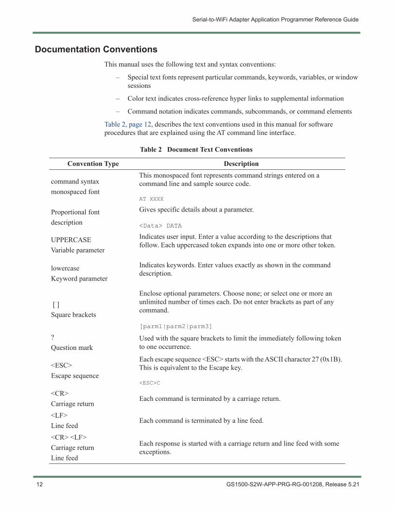
Table 2, page 12, describes the text conventions used in this manual for software procedures that are explained using the AT command line interface.
Table 2 Document Text Conventions
Convention Type Description
command syntaxmonospaced font
This monospaced font represents command strings entered on a command line and sample source code.
AT XXXX
Proportional fontdescription
Gives specific details about a parameter.
<Data> DATA
UPPERCASEVariable parameter
Indicates user input. Enter a value according to the descriptions that follow. Each uppercased token expands into one or more other token.
lowercaseKeyword parameter
Indicates keywords. Enter values exactly as shown in the command description.
[ ]Square brackets
Enclose optional parameters. Choose none; or select one or more an unlimited number of times each. Do not enter brackets as part of any command.
[parm1|parm2|parm3]
?Question mark
Used with the square brackets to limit the immediately following token to one occurrence.
<ESC>Escape sequence
Each escape sequence <ESC> starts with the ASCII character 27 (0x1B). This is equivalent to the Escape key.
<ESC>C
<CR>Carriage return
Each command is terminated by a carriage return.
<LF>Line feed
Each command is terminated by a line feed.
<CR> <LF>Carriage returnLine feed
Each response is started with a carriage return and line feed with some exceptions.
12 GS1500-S2W-APP-PRG-RG-001208, Release 5.21
Serial-to-WiFi Adapter Application Programmer Reference Guide
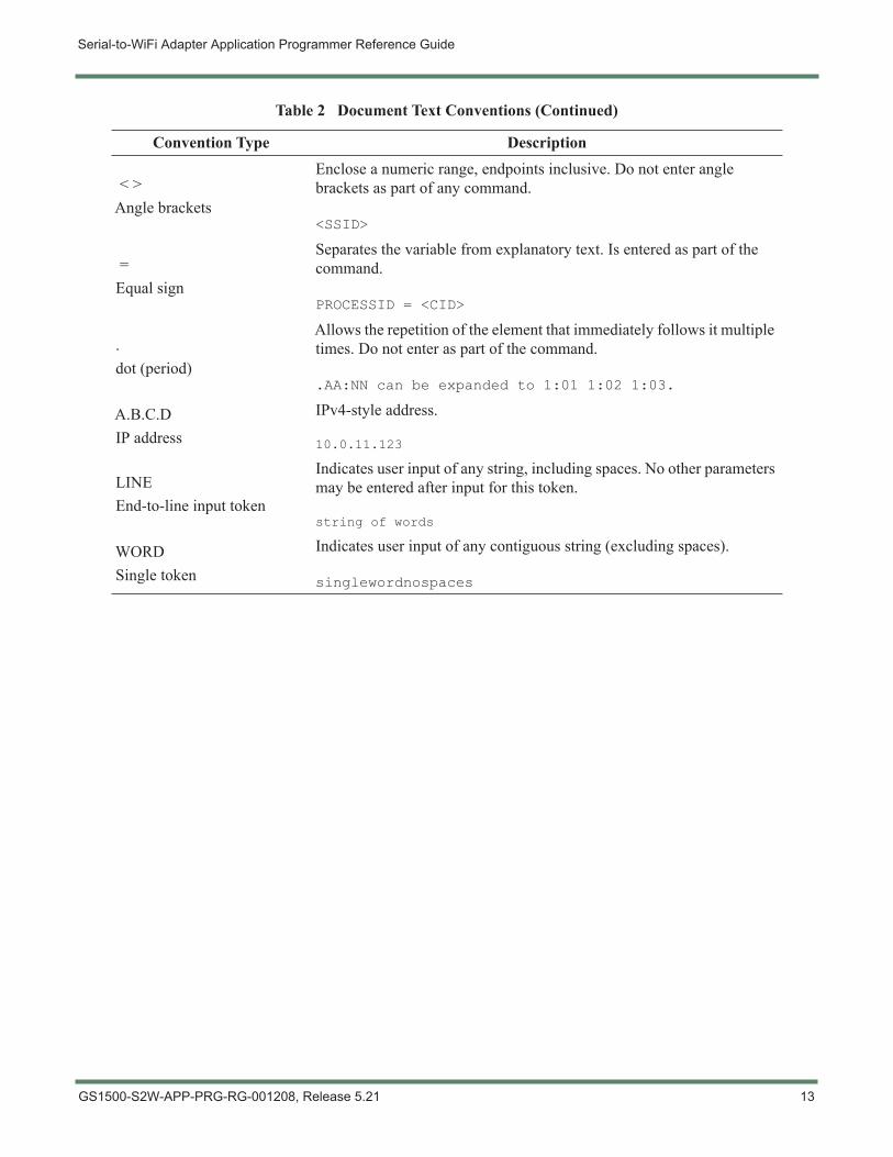
< >Angle brackets
Enclose a numeric range, endpoints inclusive. Do not enter angle brackets as part of any command.
<SSID>
=Equal sign
Separates the variable from explanatory text. Is entered as part of the command.
PROCESSID = <CID>
.dot (period)
Allows the repetition of the element that immediately follows it multiple times. Do not enter as part of the command.
.AA:NN can be expanded to 1:01 1:02 1:03.
A.B.C.DIP address
IPv4-style address.
10.0.11.123
LINEEnd-to-line input token
Indicates user input of any string, including spaces. No other parameters may be entered after input for this token.
string of words
WORDSingle token
Indicates user input of any contiguous string (excluding spaces).
singlewordnospaces
Table 2 Document Text Conventions (Continued)
Convention Type Description
GS1500-S2W-APP-PRG-RG-001208, Release 5.21 13
Serial-to-WiFi Adapter Application Programmer Reference Guide
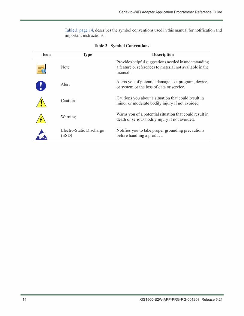
Table 3, page 14, describes the symbol conventions used in this manual for notification and important instructions.
Table 3 Symbol Conventions
Icon Type Description
NoteProvides helpful suggestions needed in understanding a feature or references to material not available in the manual.
Alert Alerts you of potential damage to a program, device, or system or the loss of data or service.
Caution Cautions you about a situation that could result in minor or moderate bodily injury if not avoided.
Warning Warns you of a potential situation that could result in death or serious bodily injury if not avoided.
Electro-Static Discharge (ESD)
Notifies you to take proper grounding precautions before handling a product.
14 GS1500-S2W-APP-PRG-RG-001208, Release 5.21
Serial-to-WiFi Adapter Application Programmer Reference Guide
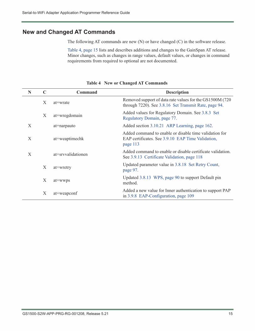
New and Changed AT CommandsThe following AT commands are new (N) or have changed (C) in the software release.
Table 4, page 15 lists and describes additions and changes to the GainSpan AT release. Minor changes, such as changes in range values, default values, or changes in command requirements from required to optional are not documented.
Table 4 New or Changed AT Commands
N C Command Description
X at+wrate Removed support of data rate values for the GS1500M (720 through 7220). See 3.8.16 Set Transmit Rate, page 94.
X at+wregdomain Added values for Regulatory Domain. See 3.8.3 Set Regulatory Domain, page 77.
X at+narpauto Added section 3.10.21 ARP Learning, page 162.
X at+weaptimechkAdded command to enable or disable time validation for EAP certificates. See 3.9.10 EAP Time Validation, page 113
X at+srvvalidationen Added command to enable or disable certificate validation. See 3.9.13 Certificate Validation, page 118
X at+wretry Updated parameter value in 3.8.18 Set Retry Count, page 97.
X at+wwps Updated 3.8.13 WPS, page 90 to support Default pin method.
X at+weapconf Added a new value for Inner authentication to support PAP in 3.9.8 EAP-Configuration, page 109
GS1500-S2W-APP-PRG-RG-001208, Release 5.21 15
Serial-to-WiFi Adapter Application Programmer Reference Guide
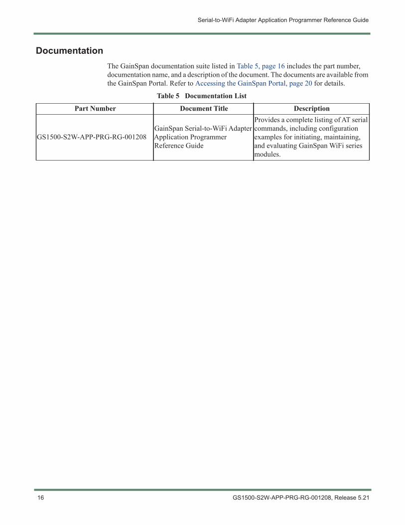
DocumentationThe GainSpan documentation suite listed in Table 5, page 16 includes the part number, documentation name, and a description of the document. The documents are available from the GainSpan Portal. Refer to Accessing the GainSpan Portal, page 20 for details.
Table 5 Documentation List
Part Number Document Title Description
GS1500-S2W-APP-PRG-RG-001208GainSpan Serial-to-WiFi Adapter Application Programmer Reference Guide
Provides a complete listing of AT serial commands, including configuration examples for initiating, maintaining, and evaluating GainSpan WiFi series modules.
16 GS1500-S2W-APP-PRG-RG-001208, Release 5.21
Serial-to-WiFi Adapter Application Programmer Reference Guide
Documentation FeedbackWe encourage you to provide feedback, comments, and suggestions so that we can improve the documentation. You can send your comments by logging into GainSpan Support Portal. If you are using e-mail, be sure to include the following information with your comments:
– Document name
– URL or page number
– Hardware release version (if applicable)
– Software release version (if applicable)
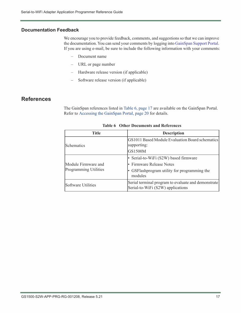
ReferencesThe GainSpan references listed in Table 6, page 17 are available on the GainSpan Portal. Refer to Accessing the GainSpan Portal, page 20 for details.
Table 6 Other Documents and References
Title Description
SchematicsGS1011 Based Module Evaluation Board schematics supporting:GS1500M
Module Firmware and Programming Utilities
• Serial-to-WiFi (S2W) based firmware• Firmware Release Notes• GSFlashprogram utility for programming the
modules
Software Utilities Serial terminal program to evaluate and demonstrate Serial-to-WiFi (S2W) applications
GS1500-S2W-APP-PRG-RG-001208, Release 5.21 17
Serial-to-WiFi Adapter Application Programmer Reference Guide
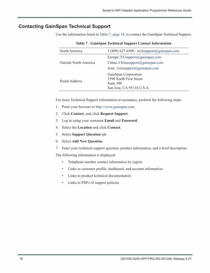
Contacting GainSpan Technical SupportUse the information listed in Table 7, page 18, to contact the GainSpan Technical Support.
For more Technical Support information or assistance, perform the following steps:
1. Point your browser to http://www.gainspan.com.
2. Click Contact, and click Request Support.
3. Log in using your customer Email and Password.
4. Select the Location and click Contact.
5. Select Support Question tab.
6. Select Add New Question.
7. Enter your technical support question, product information, and a brief description.
The following information is displayed:
• Telephone number contact information by region
• Links to customer profile, dashboard, and account information
• Links to product technical documentation
• Links to PDFs of support policies
Table 7 GainSpan Technical Support Contact Information
North America 1 (408) 627-6500 - [email protected]
Outside North AmericaEurope: [email protected]: [email protected]: [email protected]
Postal Address
GainSpan Corporation3590 North First StreetSuite 300San Jose, CA 95134 U.S.A.
18 GS1500-S2W-APP-PRG-RG-001208, Release 5.21
Serial-to-WiFi Adapter Application Programmer Reference Guide
Returning Products to GainSpanIf a problem cannot be resolved by GainSpan technical support, a Return Material Authorization (RMA) is issued. This number is used to track the returned material at the factory and to return repaired or new components to the customer as needed.
For more information about return and repair policies, see the customer support web page at: https://www.gainspan.com/secure/login.
To return a hardware component:
1. Determine the part number and serial number of the component.
2. Obtain an RMA number from Sales/Distributor Representative.
3. Provide the following information in an e-mail or during the telephone call:
– Part number and serial number of component
– Your name, organization name, telephone number, and fax number
– Description of the failure
4. The support representative validates your request and issues an RMA number for return of the components.
5. Pack the component for shipment.
Guidelines for Packing Components for ShipmentTo pack and ship individual components:
– When you return components, make sure they are adequately protected with packing materials and packed so that the pieces are prevented from moving around inside the carton.
– Use the original shipping materials if they are available.
– Place individual components in electrostatic bags.
– Write the RMA number on the exterior of the box to ensure proper tracking.
NOTE: Do not return any components to GainSpan Corporation unless you have first obtained an RMA number. GainSpan reserves the right to refuse shipments that do not have an RMA. Refused shipments will be returned to the customer by collect freight.
CAUTION! Do not stack any of the components.
GS1500-S2W-APP-PRG-RG-001208, Release 5.21 19
Serial-to-WiFi Adapter Application Programmer Reference Guide
Accessing the GainSpan PortalTo find the latest version of GainSpan documentation supporting the GainSpan product release you are interested in, you can search the GainSpan Portal website by performing the following steps:
1. Go to the GainSpan Support Portal website.
2. Log in using your customer Email and Password.
3. Click the Actions tab to buy, evaluate, or download GainSpan products.
4. Click on the Documents tab to search, download, and print GainSpan product documentation.
5. Click the Software tab to search and download the latest software versions.
6. Click the Account History tab to view customer account history.
7. Click the Legal Documents tab to view GainSpan Non-Disclosure Agreement (NDA).
8. Click Download on the Item Browser section to open or save the document.
NOTE: You must first contact GainSpan to set up an account, and obtain a customer user name and password before you can access the GainSpan Portal.
20 GS1500-S2W-APP-PRG-RG-001208, Release 5.21
Chapter 1 Interface Architecture
This chapter describes the Serial-to-WiFi adapter interface architecture.
• Overview, page 21
• Interfaces, page 21
• Architecture of Adapter, page 21
1.1 OverviewThe Serial-to-WiFi stack is used to provide WiFi capability to any device having a serial interface. This approach offloads WLAN, TCP/IP stack and network management overhead to the WiFi chip, allowing a small embedded host (for example an MCU) to communicate with other hosts on the network using a WiFi wireless link. The host processor can use serial commands to configure the Serial-to-WiFi Adapter and to create wireless and network connections.
1.2 InterfacesThe embedded host can use either one of the interfaces (UART/SPI) to connect to the Serial-to-WiFi adapter.
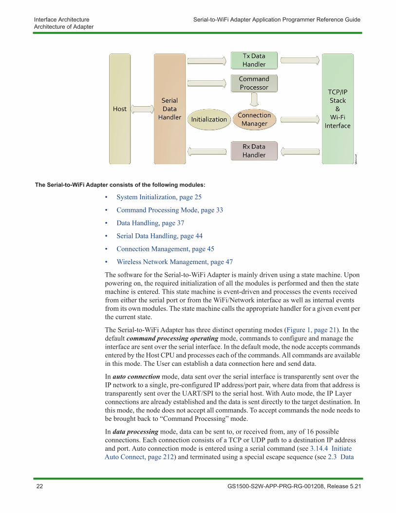
1.3 Architecture of AdapterThe overall architecture of the Serial-to-WiFi (S2W) interface is shown in Figure 1, page 21. Transmit (Tx) and Receive (Rx) Data Handlers pass messages to and from the TCP/IP network. Commands related to management of the S2W interface and the network connections are intercepted by a Command Processor. A Serial Data Handler translates data to and from a UART/SPI-compatible format.
Figure 1 Overall Architecture of the Adapter
GS1500-S2W-APP-PRG-RG-001208, Release 5.21 21
Interface Architecture Serial-to-WiFi Adapter Application Programmer Reference GuideArchitecture of Adapter
The Serial-to-WiFi Adapter consists of the following modules:
• System Initialization, page 25
• Command Processing Mode, page 33
• Data Handling, page 37
• Serial Data Handling, page 44
• Connection Management, page 45
• Wireless Network Management, page 47
The software for the Serial-to-WiFi Adapter is mainly driven using a state machine. Upon powering on, the required initialization of all the modules is performed and then the state machine is entered. This state machine is event-driven and processes the events received from either the serial port or from the WiFi/Network interface as well as internal events from its own modules. The state machine calls the appropriate handler for a given event per the current state.
The Serial-to-WiFi Adapter has three distinct operating modes (Figure 1, page 21). In the default command processing operating mode, commands to configure and manage the interface are sent over the serial interface. In the default mode, the node accepts commands entered by the Host CPU and processes each of the commands. All commands are available in this mode. The User can establish a data connection here and send data.
In auto connection mode, data sent over the serial interface is transparently sent over the IP network to a single, pre-configured IP address/port pair, where data from that address is transparently sent over the UART/SPI to the serial host. With Auto mode, the IP Layer connections are already established and the data is sent directly to the target destination. In this mode, the node does not accept all commands. To accept commands the node needs to be brought back to “Command Processing” mode.
In data processing mode, data can be sent to, or received from, any of 16 possible connections. Each connection consists of a TCP or UDP path to a destination IP address and port. Auto connection mode is entered using a serial command (see 3.14.4 Initiate Auto Connect, page 212) and terminated using a special escape sequence (see 2.3 Data
22 GS1500-S2W-APP-PRG-RG-001208, Release 5.21

Serial-to-WiFi Adapter Application Programmer Reference Guide Interface ArchitectureArchitecture of Adapter
Handling, page 37).
For each mode, configuration parameters are stored in non-volatile memory. In addition to factory-default parameter values, two user-defined profiles (0 and 1) are available. The parameter set to be used is determined by a user command (see 3.7.3 Selection of Default Profile, page 71).
GS1500-S2W-APP-PRG-RG-001208, Release 5.21 23

Interface Architecture Serial-to-WiFi Adapter Application Programmer Reference GuideArchitecture of Adapter
- This page intentionally left blank -
24 GS1500-S2W-APP-PRG-RG-001208, Release 5.21
Chapter 2 Adapter Description
This chapter describes the Serial-to-WiFi (S2W) operating modes.
• System Initialization, page 25
• Command Processing Mode, page 33
• Data Handling, page 37
• Serial Data Handling, page 44
• Connection Management, page 45
• Wireless Network Management, page 47
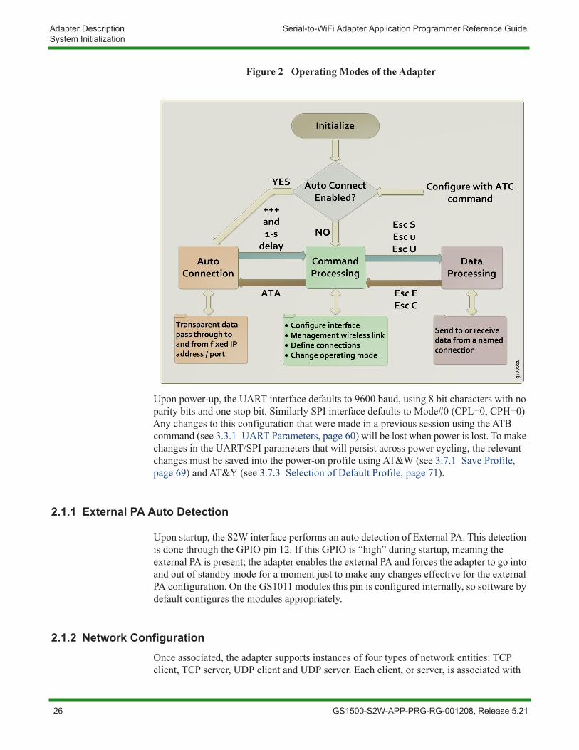
2.1 System InitializationUpon startup, the Serial-to-WiFi (S2W) interface performs the following actions as displayed in Figure 2, page 26.
During the initialization process, the module will search for a saved configuration file. The configuration file include the auto connection settings, default profile and profile settings. If a saved configuration file is available, it is loaded from non-volatile memory. If no saved configuration file, the default settings will be applied. If there are no saved parameters, the factory-default configuration is loaded.
The S2W application is initialized based on the profile settings.
If auto connection is enabled, the interface will attempt to associate with the specified network, previously set by the user (see 3.14.1 Wireless Parameters, page 208). Once associated, it will establish a TCP or UDP connection within the specified parameters. If successful, the interface will enter the Auto Connect mode, where all data received on the serial port is transmitted to the network destination and vice versa.
If auto-connection is disabled or fails, the interface enters the command processing state.
GS1500-S2W-APP-PRG-RG-001208, Release 5.21 25
Adapter Description Serial-to-WiFi Adapter Application Programmer Reference GuideSystem Initialization
Figure 2 Operating Modes of the Adapter
Upon power-up, the UART interface defaults to 9600 baud, using 8 bit characters with no parity bits and one stop bit. Similarly SPI interface defaults to Mode#0 (CPL=0, CPH=0) Any changes to this configuration that were made in a previous session using the ATB command (see 3.3.1 UART Parameters, page 60) will be lost when power is lost. To make changes in the UART/SPI parameters that will persist across power cycling, the relevant changes must be saved into the power-on profile using AT&W (see 3.7.1 Save Profile, page 69) and AT&Y (see 3.7.3 Selection of Default Profile, page 71).
2.1.1 External PA Auto Detection
Upon startup, the S2W interface performs an auto detection of External PA. This detection is done through the GPIO pin 12. If this GPIO is “high” during startup, meaning the external PA is present; the adapter enables the external PA and forces the adapter to go into and out of standby mode for a moment just to make any changes effective for the external PA configuration. On the GS1011 modules this pin is configured internally, so software by default configures the modules appropriately.
2.1.2 Network ConfigurationOnce associated, the adapter supports instances of four types of network entities: TCP client, TCP server, UDP client and UDP server. Each client, or server, is associated with
26 GS1500-S2W-APP-PRG-RG-001208, Release 5.21
Serial-to-WiFi Adapter Application Programmer Reference Guide Adapter DescriptionSystem Initialization
one or more of a possible 16 Connection Identifiers, where the CID is a single hexadecimal number. More than one such entity can exist simultaneously; and a TCP server can have multiple connections, each with its own CID. When the adapter is in Auto Connect mode (see 3.14 Auto Connection, page 208), the entity called for by the Profile is created automatically upon startup. In Command modes, servers and clients are created using specific serial commands (see 3.11 Connection Management Configuration, page 163).
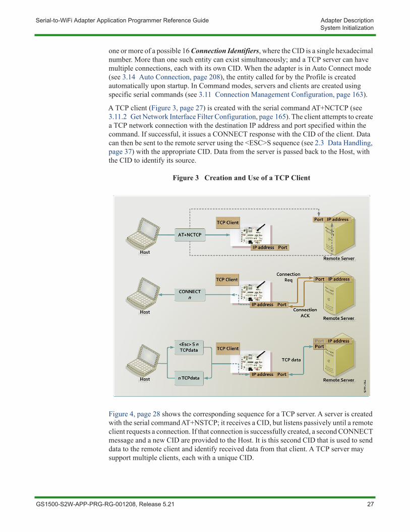
A TCP client (Figure 3, page 27) is created with the serial command AT+NCTCP (see 3.11.2 Get Network Interface Filter Configuration, page 165). The client attempts to create a TCP network connection with the destination IP address and port specified within the command. If successful, it issues a CONNECT response with the CID of the client. Data can then be sent to the remote server using the <ESC>S sequence (see 2.3 Data Handling, page 37) with the appropriate CID. Data from the server is passed back to the Host, with the CID to identify its source.
Figure 3 Creation and Use of a TCP Client
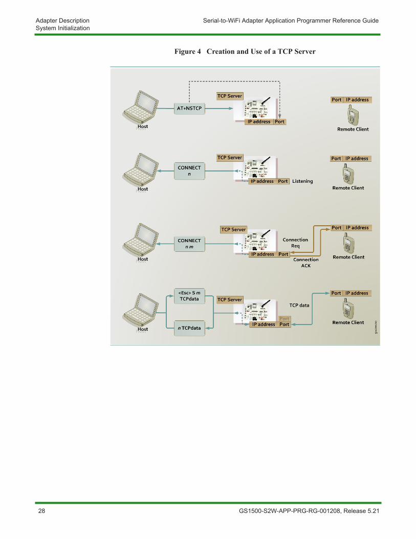
Figure 4, page 28 shows the corresponding sequence for a TCP server. A server is created with the serial command AT+NSTCP; it receives a CID, but listens passively until a remote client requests a connection. If that connection is successfully created, a second CONNECT message and a new CID are provided to the Host. It is this second CID that is used to send data to the remote client and identify received data from that client. A TCP server may support multiple clients, each with a unique CID.
GS1500-S2W-APP-PRG-RG-001208, Release 5.21 27
Adapter Description Serial-to-WiFi Adapter Application Programmer Reference GuideSystem Initialization
Figure 4 Creation and Use of a TCP Server
28 GS1500-S2W-APP-PRG-RG-001208, Release 5.21
Serial-to-WiFi Adapter Application Programmer Reference Guide Adapter DescriptionSystem Initialization
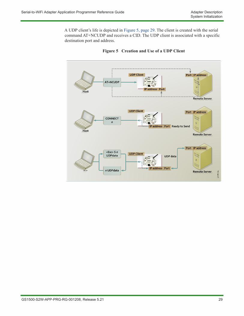
A UDP client’s life is depicted in Figure 5, page 29. The client is created with the serial command AT+NCUDP and receives a CID. The UDP client is associated with a specific destination port and address.
Figure 5 Creation and Use of a UDP Client
GS1500-S2W-APP-PRG-RG-001208, Release 5.21 29
Adapter Description Serial-to-WiFi Adapter Application Programmer Reference GuideSystem Initialization
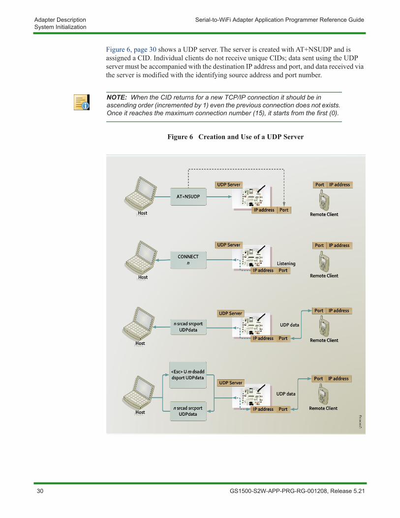
Figure 6, page 30 shows a UDP server. The server is created with AT+NSUDP and is assigned a CID. Individual clients do not receive unique CIDs; data sent using the UDP server must be accompanied with the destination IP address and port, and data received via the server is modified with the identifying source address and port number.
Figure 6 Creation and Use of a UDP Server
NOTE: When the CID returns for a new TCP/IP connection it should be in ascending order (incremented by 1) even the previous connection does not exists. Once it reaches the maximum connection number (15), it starts from the first (0).
30 GS1500-S2W-APP-PRG-RG-001208, Release 5.21
Serial-to-WiFi Adapter Application Programmer Reference Guide Adapter DescriptionSystem Initialization
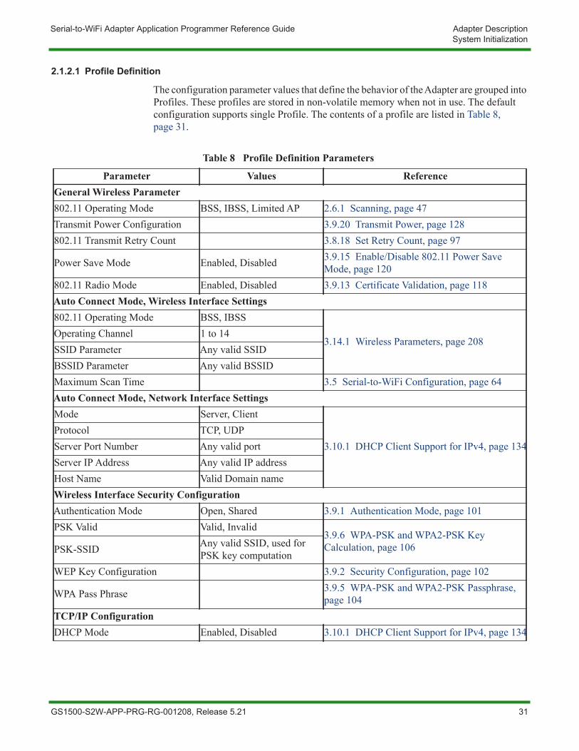
2.1.2.1 Profile Definition
The configuration parameter values that define the behavior of the Adapter are grouped into Profiles. These profiles are stored in non-volatile memory when not in use. The default configuration supports single Profile. The contents of a profile are listed in Table 8, page 31.
Table 8 Profile Definition Parameters
Parameter Values ReferenceGeneral Wireless Parameter802.11 Operating Mode BSS, IBSS, Limited AP 2.6.1 Scanning, page 47Transmit Power Configuration 3.9.20 Transmit Power, page 128802.11 Transmit Retry Count 3.8.18 Set Retry Count, page 97
Power Save Mode Enabled, Disabled 3.9.15 Enable/Disable 802.11 Power Save Mode, page 120
802.11 Radio Mode Enabled, Disabled 3.9.13 Certificate Validation, page 118Auto Connect Mode, Wireless Interface Settings802.11 Operating Mode BSS, IBSS
3.14.1 Wireless Parameters, page 208Operating Channel 1 to 14SSID Parameter Any valid SSIDBSSID Parameter Any valid BSSIDMaximum Scan Time 3.5 Serial-to-WiFi Configuration, page 64Auto Connect Mode, Network Interface SettingsMode Server, Client
3.10.1 DHCP Client Support for IPv4, page 134Protocol TCP, UDPServer Port Number Any valid portServer IP Address Any valid IP addressHost Name Valid Domain nameWireless Interface Security ConfigurationAuthentication Mode Open, Shared 3.9.1 Authentication Mode, page 101PSK Valid Valid, Invalid
3.9.6 WPA-PSK and WPA2-PSK Key Calculation, page 106PSK-SSID Any valid SSID, used for
PSK key computationWEP Key Configuration 3.9.2 Security Configuration, page 102
WPA Pass Phrase 3.9.5 WPA-PSK and WPA2-PSK Passphrase, page 104
TCP/IP ConfigurationDHCP Mode Enabled, Disabled 3.10.1 DHCP Client Support for IPv4, page 134
GS1500-S2W-APP-PRG-RG-001208, Release 5.21 31
Adapter Description Serial-to-WiFi Adapter Application Programmer Reference GuideSystem Initialization
IP Address Valid IP address3.10.2 Static Configuration of Network Parameters for IPv4, page 136Net Mask Address Valid mask
Default Gateway Address Valid IP addressDNS1 Valid DNS1 IP address
3.10.6 MDNS Services Registration, page 143DNS2 Valid DNS2 IP addressUART ConfigurationEcho Mode Enabled, Disabled 3.2.2 Echo, page 58Verbose Mode Enabled, Disabled 3.2.3 Verbose, page 59Bits Per Character 5, 6, 7, 8
3.3.1 UART Parameters, page 60Number of Stop Bits 1, 2Parity Type No, Odd, EvenSoftware Flow Control Mode Enabled, Disabled 3.3.2 Software Flow Control, page 61Hardware Flow Control Mode Enabled, Disabled 3.3.3 Hardware Flow Control, page 61Baud Rate 3.3.1 UART Parameters, page 60Limits and TimeoutsNetwork Connection Timeout Units of 10 milliseconds
3.5 Serial-to-WiFi Configuration, page 64
Auto Association Timeout Units of 10 millisecondsTCP Connection Timeout Units of 10 millisecondsAssociation Retry Count Units of millisecondsNagle Wait Time Units of 10 millisecondsScan Time Units of millisecondsNCM L4 Reconnect Interval Units of millisecondsNCM L4 Reconnect Count Units of numbersSPI ConfigurationSPI Clock Polarity and Clock Phase 0, 1 3.4.1 SPI Interface Configuration, page 63
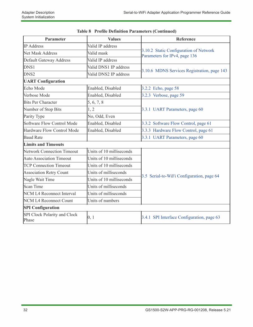
Table 8 Profile Definition Parameters (Continued)
Parameter Values Reference
32 GS1500-S2W-APP-PRG-RG-001208, Release 5.21
Serial-to-WiFi Adapter Application Programmer Reference Guide Adapter DescriptionCommand Processing Mode
2.2 Command Processing ModeIn Command mode, the application receives commands over the serial port. Commands are processed line by line.
Verbose Mode is used when referring to commands being executed, refers to the displaying of status of any command executed in ASCII (human readable) format. When the Verbose Mode is disabled, the output will simply be in numeric digits, each digit indicating a particular status. Verbose Mode is enabled by default.
If echo is enabled then each character is echoed back on the serial port.
Each command is terminated with a carriage return <CR> or line feed <LF>.
Each response is started with a carriage return <CR> and line feed<LF>, with the exception of the responses to the following commands:
The response to the following group of commands starts with a line feed <LF> only:
AT+WA
AT+NSTAT
AT+WPAPSK=<SSID>,<Passphrase>
AT+NSET=<IP Address>,<Subnet Mask>,<Gateway IP Address> (valid after association)
AT+TRACEROUTE=<IP Address>
AT+PING=<IP Address>
ATA
AT+NDHCP (after association)
The response to the following group of commands starts with a line feed and carriage return: <LF><CR>:
AT+HTTPOPEN=<IP Address>
Unless otherwise specified, if Verbose Mode is enabled, then the response to a successful command is the characters OK. The response to an unsuccessful command is the word ERROR, followed by a detailed error message, if available. If verbose mode is disabled, command responses is numerical with OK having a value of 0 and error codes represented by positive integers.
The commands are described in Chapter 3 Commands for Command Processing Mode, page 55.
GS1500-S2W-APP-PRG-RG-001208, Release 5.21 33
Adapter Description Serial-to-WiFi Adapter Application Programmer Reference GuideCommand Processing Mode
2.2.1 Auto ConnectionIf auto connection is enabled, then upon startup the Adapter will:
1. Attempt to associate to or from the specified network, for a maximum time of Auto Associate Timeout (see 3.5 Serial-to-WiFi Configuration, page 64).
2. On successful association, attempt to establish a network connection based on the specified parameters.
3. On successful connection establishment, enter the pass-through auto connect mode
4. On failure, enter the command processing state.
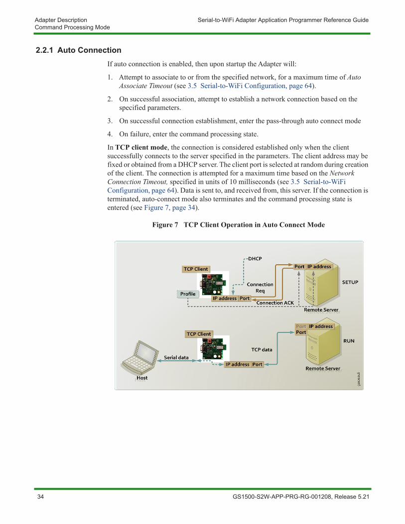
In TCP client mode, the connection is considered established only when the client successfully connects to the server specified in the parameters. The client address may be fixed or obtained from a DHCP server. The client port is selected at random during creation of the client. The connection is attempted for a maximum time based on the Network Connection Timeout, specified in units of 10 milliseconds (see 3.5 Serial-to-WiFi Configuration, page 64). Data is sent to, and received from, this server. If the connection is terminated, auto-connect mode also terminates and the command processing state is entered (see Figure 7, page 34).
Figure 7 TCP Client Operation in Auto Connect Mode
34 GS1500-S2W-APP-PRG-RG-001208, Release 5.21
Serial-to-WiFi Adapter Application Programmer Reference Guide Adapter DescriptionCommand Processing Mode
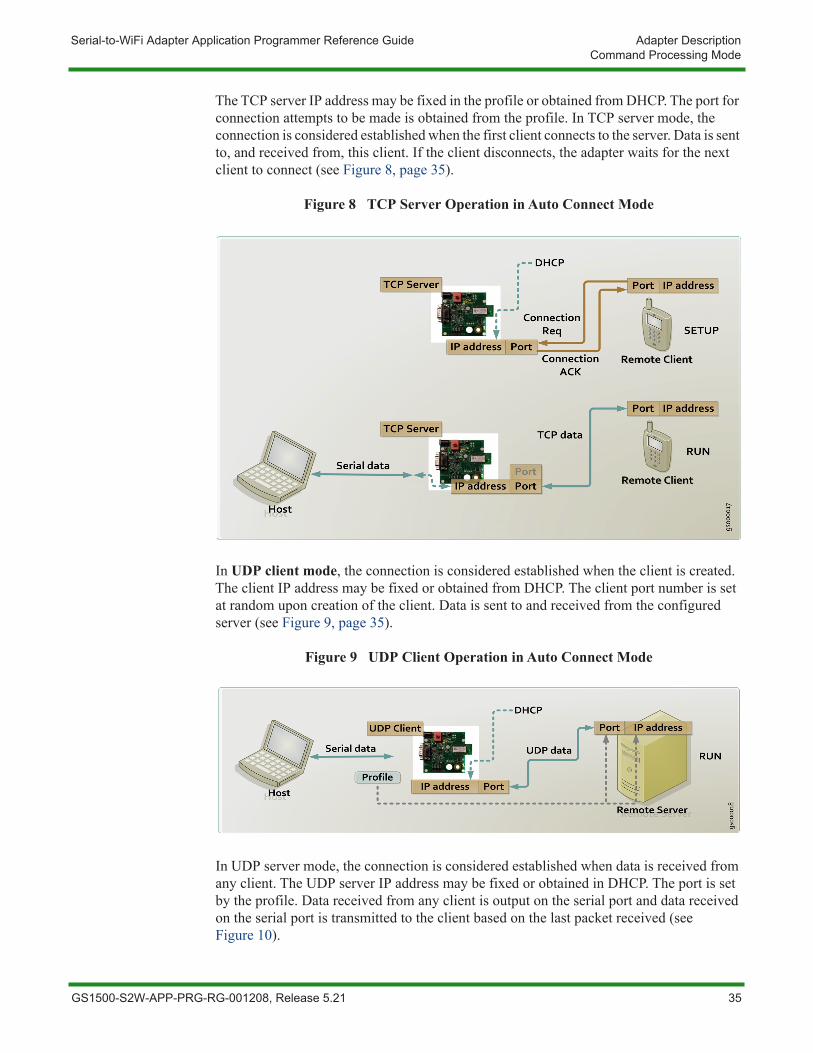
The TCP server IP address may be fixed in the profile or obtained from DHCP. The port for connection attempts to be made is obtained from the profile. In TCP server mode, the connection is considered established when the first client connects to the server. Data is sent to, and received from, this client. If the client disconnects, the adapter waits for the next client to connect (see Figure 8, page 35).
Figure 8 TCP Server Operation in Auto Connect Mode
In UDP client mode, the connection is considered established when the client is created. The client IP address may be fixed or obtained from DHCP. The client port number is set at random upon creation of the client. Data is sent to and received from the configured server (see Figure 9, page 35).
Figure 9 UDP Client Operation in Auto Connect Mode
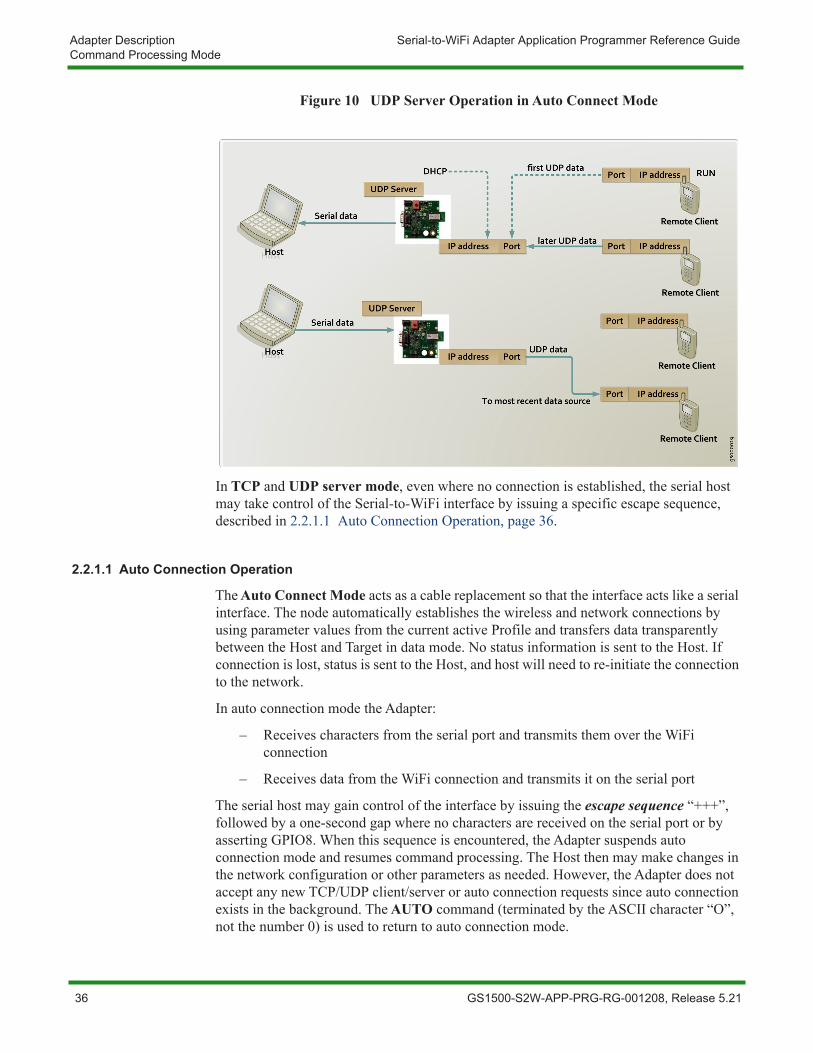
In UDP server mode, the connection is considered established when data is received from any client. The UDP server IP address may be fixed or obtained in DHCP. The port is set by the profile. Data received from any client is output on the serial port and data received on the serial port is transmitted to the client based on the last packet received (see Figure 10).
GS1500-S2W-APP-PRG-RG-001208, Release 5.21 35
Adapter Description Serial-to-WiFi Adapter Application Programmer Reference GuideCommand Processing Mode
Figure 10 UDP Server Operation in Auto Connect Mode
In TCP and UDP server mode, even where no connection is established, the serial host may take control of the Serial-to-WiFi interface by issuing a specific escape sequence, described in 2.2.1.1 Auto Connection Operation, page 36.
2.2.1.1 Auto Connection Operation
The Auto Connect Mode acts as a cable replacement so that the interface acts like a serial interface. The node automatically establishes the wireless and network connections by using parameter values from the current active Profile and transfers data transparently between the Host and Target in data mode. No status information is sent to the Host. If connection is lost, status is sent to the Host, and host will need to re-initiate the connection to the network.
In auto connection mode the Adapter:
– Receives characters from the serial port and transmits them over the WiFi connection
– Receives data from the WiFi connection and transmits it on the serial port
The serial host may gain control of the interface by issuing the escape sequence “+++”, followed by a one-second gap where no characters are received on the serial port or by asserting GPIO8. When this sequence is encountered, the Adapter suspends auto connection mode and resumes command processing. The Host then may make changes in the network configuration or other parameters as needed. However, the Adapter does not accept any new TCP/UDP client/server or auto connection requests since auto connection exists in the background. The AUTO command (terminated by the ASCII character “O”, not the number 0) is used to return to auto connection mode.
36 GS1500-S2W-APP-PRG-RG-001208, Release 5.21
Serial-to-WiFi Adapter Application Programmer Reference Guide Adapter DescriptionData Handling
In auto connection mode, the Nagle Algorithm Wait Time (see 3.5 Serial-to-WiFi Configuration, page 64) can be used to buffer any characters to be sent, in order to avoid sending a large number of packets with small payloads onto the network. The wait time is specified in units of 10 milliseconds. This functionality is available for both UDP and TCP connections.
When L2, L3, or L4 disconnects, GPIO19 goes low and the host stops sending data
2.3 Data HandlingIn Data Processing Mode, data transfers are managed using various escape sequences. Each escape sequence starts with the ASCII character 27 (0x1B); this is equivalent to the ESC key. The encoding of data and related commands are described in the following pages. This encoding is used for both transmitted and received data.
The network destination, or destination source, for a given data packet is established by means of a Connection Identifier, and represented as a single hexadecimal number. Data is transferred on a per CID basis. Data is normally buffered until the end-of-data escape sequence is received. However, if the amount of data exceeds the size of the data buffer, the data received, thus far, is sent immediately. The data buffer size depends on the implementation, but is usually one MTU (1400 bytes).
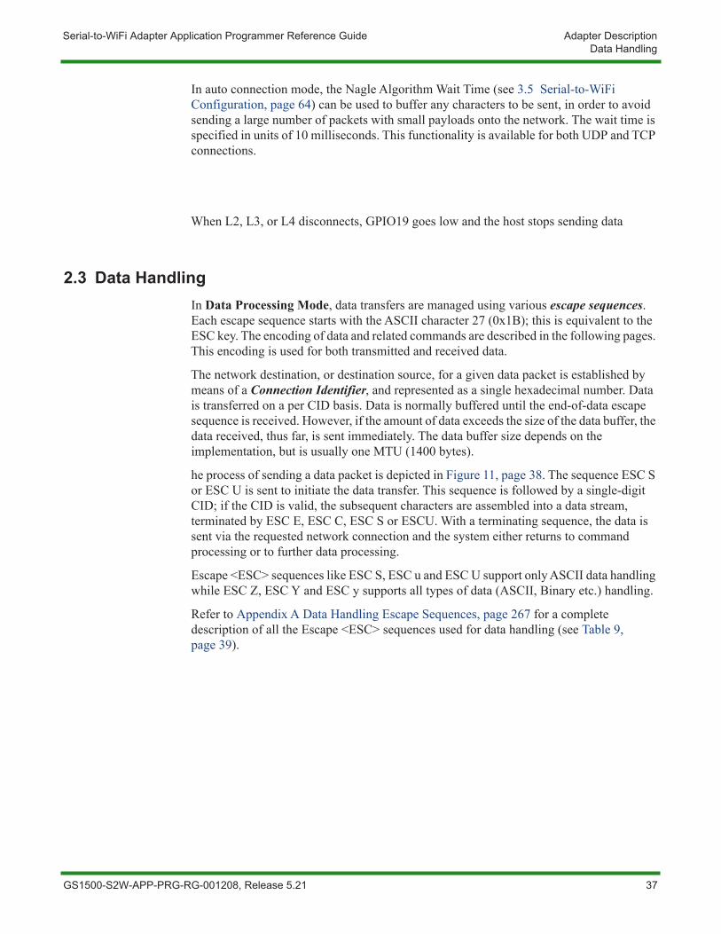
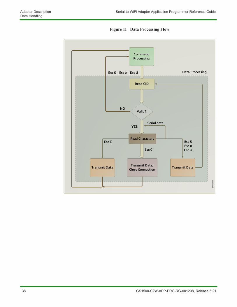
he process of sending a data packet is depicted in Figure 11, page 38. The sequence ESC S or ESC U is sent to initiate the data transfer. This sequence is followed by a single-digit CID; if the CID is valid, the subsequent characters are assembled into a data stream, terminated by ESC E, ESC C, ESC S or ESCU. With a terminating sequence, the data is sent via the requested network connection and the system either returns to command processing or to further data processing.
Escape <ESC> sequences like ESC S, ESC u and ESC U support only ASCII data handling while ESC Z, ESC Y and ESC y supports all types of data (ASCII, Binary etc.) handling.
Refer to Appendix A Data Handling Escape Sequences, page 267 for a complete description of all the Escape <ESC> sequences used for data handling (see Table 9, page 39).
GS1500-S2W-APP-PRG-RG-001208, Release 5.21 37
Adapter Description Serial-to-WiFi Adapter Application Programmer Reference GuideData Handling
Figure 11 Data Processing Flow
38 GS1500-S2W-APP-PRG-RG-001208, Release 5.21
Serial-to-WiFi Adapter Application Programmer Reference Guide Adapter DescriptionData Handling
2.3.1 Bulk Data Tx and RxIn Bulk Data Mode, data transfers are managed using escape sequences (ESC Z, ESC Y and ESC y). Each escape sequence (see Table 10, page 40) starts with the Escape <ESC> key (ASCII character 27 (0x1B)). Encoding is used for both transmitted and received data. Enable bulk data by using command “AT+BDATA=” (1 is enable and 0 is disable).
The format of a bulk data frame for TCP client, TCP server, or UDP client is:
<ESC>Z<CID><Data Length xxxx 4 ascii char><data>
The contents of < > are a byte or byte stream.
– CID is connection identifier (UDP, TCP, etc.; as derived when TCP socket is created by issuing the command: AT+NCTCP, for example.)
– Data Length is 4 ASCII character represents decimal value i.e. 1400 byte (0x31 0x34 0x30 0x30).
– The Data Length range should be 1 to 1400 bytes when sending to GainSpan module from Host and it will be 1 to 1500 bytes when Host is receiving from GainSpan module
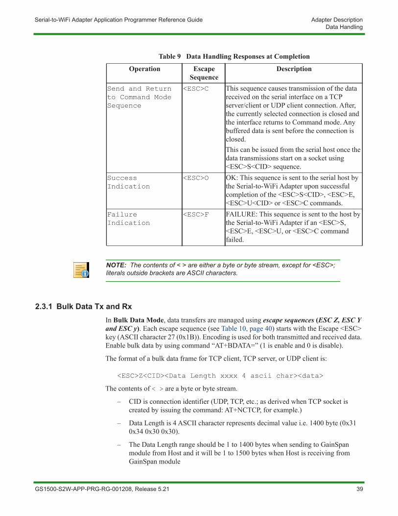
Table 9 Data Handling Responses at Completion
Operation Escape Sequence
Description
Send and Return to Command Mode Sequence
<ESC>C This sequence causes transmission of the data received on the serial interface on a TCP server/client or UDP client connection. After, the currently selected connection is closed and the interface returns to Command mode. Any buffered data is sent before the connection is closed.This can be issued from the serial host once the data transmissions start on a socket using <ESC>S<CID> sequence.
Success Indication
<ESC>O OK: This sequence is sent to the serial host by the Serial-to-WiFi Adapter upon successful completion of the <ESC>S<CID>, <ESC>E, <ESC>U<CID> or <ESC>C commands.
Failure Indication
<ESC>F FAILURE: This sequence is sent to the host by the Serial-to-WiFi Adapter if an <ESC>S, <ESC>E, <ESC>U, or <ESC>C command failed.
NOTE: The contents of < > are either a byte or byte stream, except for <ESC>; literals outside brackets are ASCII characters.
GS1500-S2W-APP-PRG-RG-001208, Release 5.21 39
Adapter Description Serial-to-WiFi Adapter Application Programmer Reference GuideData Handling
User Data size must match the specified Data Length. Ignore all command or Escape <ESC> sequence in between data pay load. User should send the specified length of data to the adapter irrespective of any asynchronous events happened on the adapter so that the adapter can start receiving next commands.
For example, if CID value is 3, then:
To send a 5 byte user data (e.g. ABCDE) for a TCP client connection, the format will be:
<ESC>Z30005ABCDE
To send a 512 byte user data for a TCP client connection, the format will be:
<ESC>Z30512<512 bytes of user data>
To send data on UDP server, the bulk data frame format is:
<ESC>Y<CID><Ip address>:<port>:<Data Length xxxx 4 ascii char><data>
When receiving data on UDP server, the format of a bulk data frame is:
<ESC>y<CID><IP address><space><port><horizontal tab><Data Length xxxx 4 ascii char><data>
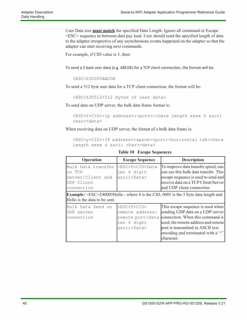
Table 10 Escape Sequences
Operation Escape Sequence DescriptionBulk Data transfer on TCP Server/Client and UDP Client connection
<ESC>Z<CID>Data Len 4 digit ascii<Data>
To improve data transfer speed, one can use this bulk data transfer. This escape sequence is used to send and receive data on a TCP Client/Server and UDP client connection.
Example: <ESC>Z40005Hello - where 4 is the CID, 0005 is the 5 byte data length and Hello is the data to be sent.Bulk Data Send on UDP server connection
<ESC>Y<CID> remote address: remote port:Data Len 4 dight ascii<Data>
This escape sequence is used when sending UDP data on a UDP server connection. When this command is used, the remote address and remote port is transmitted in ASCII text encoding and terminated with a “:” character.
40 GS1500-S2W-APP-PRG-RG-001208, Release 5.21
Serial-to-WiFi Adapter Application Programmer Reference Guide Adapter DescriptionData Handling
2.3.1.1 Raw Data Handling (BACNET Support Only)
In Raw Data Mode, data transfers are managed using escape sequences. Each escape sequence starts with the ASCII character 27 (0x1B), the equivalent to the Escape <ESC> key. The encoding of data is described below. Encoding is used for both transmitted and received data. The Raw Ethernet Support Enable command (see 3.11.19 Enable/Disable Raw Ethernet Support, page 187) must be issued before sending or receiving raw data through the Adapter.
The format of a raw-data frame is:
<ESC>:R:<Length>:<DstAddr><SrcAddr><EtherType><Raw-Payload>
The contents of < > are a byte or byte stream.
Table 11, page 41 describes the Raw Data Frame parameters.
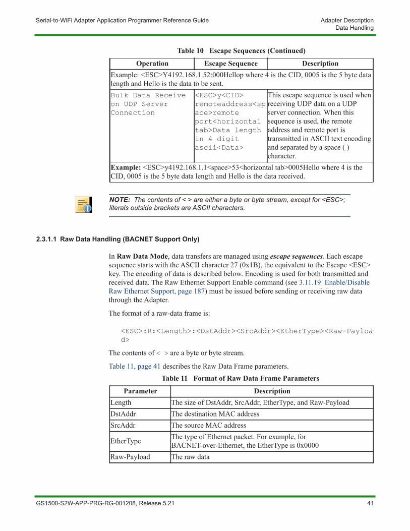
Example: <ESC>Y4192.168.1.52:000Hellop where 4 is the CID, 0005 is the 5 byte data length and Hello is the data to be sent.Bulk Data Receive on UDP Server Connection
<ESC>y<CID> remoteaddress<space>remote port<horizontal tab>Data length in 4 digit ascii<Data>
This escape sequence is used when receiving UDP data on a UDP server connection. When this sequence is used, the remote address and remote port is transmitted in ASCII text encoding and separated by a space ( ) character.
Example: <ESC>y4192.168.1.1<space>53<horizontal tab>0005Hello where 4 is the CID, 0005 is the 5 byte data length and Hello is the data received.
NOTE: The contents of < > are either a byte or byte stream, except for <ESC>; literals outside brackets are ASCII characters.
Table 10 Escape Sequences (Continued)
Operation Escape Sequence Description
Table 11 Format of Raw Data Frame Parameters
Parameter DescriptionLength The size of DstAddr, SrcAddr, EtherType, and Raw-PayloadDstAddr The destination MAC addressSrcAddr The source MAC address
EtherType The type of Ethernet packet. For example, for BACNET-over-Ethernet, the EtherType is 0x0000
Raw-Payload The raw data
GS1500-S2W-APP-PRG-RG-001208, Release 5.21 41
Adapter Description Serial-to-WiFi Adapter Application Programmer Reference GuideData Handling
2.3.2 Software Flow ControlThe Software Flow Control (for UART interface) works only with ASCII data transfers and cannot be used for binary data. For SPI interface and use of flow control (see 3.20.3 SPI Interface Handling, page 238).
If software flow control is enabled, and the interface receives an XOFF character from the serial host, it stops sending to the host until it receives an XON character. If the Adapter is receiving data over the wireless connection during the time that XOFF is enabled, it is possible for the wireless buffer to become full before XON is received. In such a case, data from the network will be lost.
If software flow control is enabled, then the interface sends an XOFF character to the host when it will be unable to service the serial port. The XON character is sent when the interface is once again able to accept data over the serial port.
NOTE: With initialization, the Adapter treats the serial channel as clear with no restrictions on data transmission or reception; no explicit XON by the Adapter or required from the Host, even if flow control is enabled.
42 GS1500-S2W-APP-PRG-RG-001208, Release 5.21
Serial-to-WiFi Adapter Application Programmer Reference Guide Adapter DescriptionData Handling
2.3.3 Hardware Flow ControlThe Hardware Flow Control is a handshake mechanism between the Serial host and S2W adapter on UART interface, using two additional CTS and RTS connections. This feature prevents the UART hardware FIFO overflow on S2W adapter due to high speed data transmission from/to the S2W adapter. If hardware flow control is enabled, an RTS/CTS handshake will occur between the serial host and the Adapter. This is a hardware feature and available only for UART interface.
The S2W adapter uses both CTS and RTS signals as “low” to indicate the readiness to send or receive data from serial host.
GS1500-S2W-APP-PRG-RG-001208, Release 5.21 43
Adapter Description Serial-to-WiFi Adapter Application Programmer Reference GuideSerial Data Handling
2.4 Serial Data HandlingThe Serial Data Handler receives and transmits data to and from the hardware serial controller. Data read from the serial port is passed to:
– The command processor in command mode
– The Tx data handler in data mode
– The auto connection mode processor for data transfer in auto connection mode
Then Data is transferred on the serial port from:
– The command processor in order to output responses to commands
– The Tx data handler in order to output incoming packets
– The Rx data handler in order to output incoming packets
– The auto connection handler in order to output incoming data
– The connection manager in order to output status indications
– The wireless connection manager in order to output status indications
When configured in Auto Connection Mode, the Adapter enters directly into Data Processing Mode after the completing the connection without sending any status information to the Host.
44 GS1500-S2W-APP-PRG-RG-001208, Release 5.21
Serial-to-WiFi Adapter Application Programmer Reference Guide Adapter DescriptionConnection Management
2.5 Connection ManagementThe Connection Management module is responsible for processing connection-related events. The interface provides UDP and TCP sockets (similar to the familiar BSD network sockets). Each socket may represent either a server or client connection. Each connection has a unique, single-digit hexadecimal value (0 to F), for the CID. The allowed maximum number of connections (up to 16) may be specified at compile time.
2.5.1 Packet ReceptionWhen a packet is received on any open connection, and the application is not currently in auto-connect mode, the packet is transferred on the UART/SPI in the form described in 2.3 Data Handling, page 37. Received data payloads are encoded with the appropriate Escape <ESC> sequence. The connection ID is used to inform the serial host of the origin of an IP data packet. The source IP address and port are provided along with the data when a UDP packet is received.
If auto-connect mode is enabled and a packet is received on the auto-connected CID, the packet data is sent without modification over the UART/SPI to the serial host.
2.5.2 Remote CloseIf a TCP connection is terminated by disconnection from the remote end, an unsolicited ASCII-format response of the form DISCONNECT Connection ID is sent to the serial host, and the specified CID should be considered unavailable. If the connection ends because the remote server has shut down, the unsolicited response ERROR:SOCKET FAILURE Connection ID will be sent to the host.
NOTE: This single pool of CIDs is used for TCP, UDP, Server, and Client connections.
NOTE: A data packet from the remote client or server containing the same ASCII characters CLOSE Connection ID is treated as data rather than a command and forwarded to the serial host.
GS1500-S2W-APP-PRG-RG-001208, Release 5.21 45
Adapter Description Serial-to-WiFi Adapter Application Programmer Reference GuideConnection Management
2.5.3 TCP Server ConnectionsUpon deployment of incoming TCP connections on a socket, the incoming connection is allowed if the limit on the maximum number of connections has not been reached.
There is an unsolicited response of the form:
CONNECT <server CID> <new CID> <ip> <port>, where:
– server CID is the CID of the server where the connection has arrived
– new CID is the CID allocated for this client connections
– ip and port is the IP and Port of the client encoded in the binary encoding used for UDP server data packets described in 2.3 Data Handling, page 37 above is sent to the serial host. The host can use the IP address to ascertain the source of the TCP connection request.The TCP server has no timeout limitation for an incoming connect request. It waits indefinitely, until a CLOSE command is received.
NOTE: If Verbose mode is disabled (see 3.2.3 Verbose, page 59), the word CONNECT in the unsolicited response is replaced by the number 7.
46 GS1500-S2W-APP-PRG-RG-001208, Release 5.21
Serial-to-WiFi Adapter Application Programmer Reference Guide Adapter DescriptionWireless Network Management
2.6 Wireless Network Management
2.6.1 ScanningThe Serial-to-WiFi interface can instruct the WiFi radio to scan for access points and ad hoc networks with a specified SSID, BSSID and/or channel for a specified scan time. Scanning can be performed to find networks with a specific SSID or BSSID, networks operating on a specific radio channel or a combination of these constraints.
2.6.1.1 Association
The Serial-to-WiFi interface performs all the actions required to join an infrastructure IP network:
– Scan for a specific AP (AT+WS) – see 3.8.7 Scanning, page 81
– Authenticate the specified network using the configured authentication mode (AT+WAUTH) – see 3.9.1 Authentication Mode, page 101 for more information
– Associate to the AP (AT+WA) – see 3.8.11 Associate with a Network, or Start an Ad Hoc or Infrastructure (AP) Network, page 87
– Perform security negotiation if required
– Change state to Wireless Connected
– Initialize the networking stack using the configured static IP address or via DHCP (AT+NDHCP) – see 3.10.1 DHCP Client Support for IPv4, page 134
In ad hoc mode, the interface can:
– Scan for a specified Ad-hoc Network
– Join the ad hoc network, if it exists
– If the ad hoc network does not exist, create a new ad hoc network to join
– Perform security negotiation, if required
– Change state to Wireless Connected
– Initialize the networking stack using the configured static IP address or via DHCP
GS1500-S2W-APP-PRG-RG-001208, Release 5.21 47

Adapter Description Serial-to-WiFi Adapter Application Programmer Reference GuideWireless Network Management
2.6.1.2 Response Codes
The possible responses sent by the Adapter to the serial host are categorized as follows:
• Synchronous messages
• Asynchronous messages
– Exception messages
Table 12, page 48 lists the response codes with all characters including: <CR> or <LF> that would be seen on the MCU interface.
Table 12 Response Codes
No. ASCII Character
Response ASCII String Meaning
1 0 S2W_SUCCESS “\r\nOK\r\n” Command Request Success2 1 S2W_FAILURE “\r\nERROR\r\n” Command Request Failed
3 2 S2W_EINVAL “\r\nERROR:INVALID INPUT\r\n”
Invalid Command or Option or Parameter
4 3 S2W_SOCK_FAIL“\r\n\ERROR:SOCKET FAILURE<CID>\r\n”
Socket Operation Failed
5 4 S2W_ENOCID “\r\n\ERROR: NO CID\r\n”
GS node support only 16 CIDs, it will not create the next connection (i.e., 17th connection) when all 16 CIDs are being active.
6 5 S2W_EBADCID "\r\nERROR: INVALID CID\r\n" Invalid Connection Identifier
7 6 S2W_ENOTSUP "\r\nERROR: NOT SUPPORTED\r\n"
Unsupported wireless encryption mode. (Enterprise security)
8 7 S2W_CON_SUCCESS "\r\nCONNECT <CID>\r\n\r\nOK\r\n”
TCP/IP connection successful where <CID> = the new CID in hexadecimal format. It is followed by command request success.
9 8 S2W_ECIDCLOSE “\r\nDISCONNECT <CID>\r\n"
TCP/IP connection with the given CID is closed. This response is sent to the host when a connection is closed either by the remote device or by the serial host.
48 GS1500-S2W-APP-PRG-RG-001208, Release 5.21

Serial-to-WiFi Adapter Application Programmer Reference Guide Adapter DescriptionWireless Network Management
10 9 S2W_LINK_LOST "\r\nDISASSOCIATED\r\n"
GS node is not associated to a wireless network.If a GS node is no longer associated to any AP and MCU sends commands such as AT+NCTCP/UDP or AT+NSTCP/UDP, then DISASSOCIATED response code is returned to MCU.
11 10 S2W_DISASSO_EVT “\r\n\r\nDisassociation Event\r\n\r\n” Wireless network association lost
12 11 S2W_STBY_TMR_EVT "\r\nOut of StandBy-Timer\r\n"
Wake up from Standby due to RTC timer expiration.
13 12 S2W_STBY_ALM_EVT "\r\n\n\rOut of StandBy-Alarm\r\n\r\n"
Wake up from Standby due to receipt of an Alarm signal
14 13 S2W_DPSLEEP_EVT "\r\n\r\nOut of Deep Sleep\r\n\r\n\r\nOK\r\n”
Wake from Deep Sleep followed by command request success
15 14 S2W_BOOT_UNEXPECTED_EVT
"\r\n\r\nUnExpected Warm Boot(Possibly Low Battery)\r\n\r\n"
Unexpected reset. Possible reasons: external reset or low battery
16 15 S2W_ENOIP "\r\nERROR: IP CONFIG FAIL\r\n"
IP configuration has failed. This message also can come asynchronously when there is a DHCP renew failure.
17 16 Boot Message “\r\nSerial2WiFi APP\r\n” Boot message for MIx modules
18 17 Boot Message “\r\nSerial2WiFi APP-Ext.PA\r\n” Boot message for MEx modules
19 18 Nwconnection success “\r\nNWCONN-SUCCESS\r\n”
The L2+L3 connection success message for the ncm auto connection
20 19 S2W_NEWIP “\r\nIP CONFIG-NEW IP\r\n”
DHCP renewal success with a new IP address
21 20 Reset Message “\n\rAPP Reset-Wlan-Wd\r\n"
Boot message for an adapter reset with WLAN watch dog
22 21 Reset Message "\n\rAPP Reset-App-Wd\r\n"
Boot message for an adapter reset with Application watch dog
23 22 Reset Message "\n\rAPP Reset-Wlan SW Reset\r\n”
Boot message for an adapter reset with WLAN reset
Table 12 Response Codes (Continued)
No. ASCII Character
Response ASCII String Meaning
GS1500-S2W-APP-PRG-RG-001208, Release 5.21 49
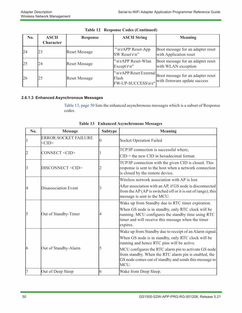
Adapter Description Serial-to-WiFi Adapter Application Programmer Reference GuideWireless Network Management
2.6.1.3 Enhanced Asynchronous Messages
Table 13, page 50 lists the enhanced asynchronous messages which is a subset of Response codes.
24 23 Reset Message "\n\rAPP Reset-App SW Reset\r\n”
Boot message for an adapter reset with Application reset
25 24 Reset Message "\n\rAPP Reset-Wlan Except\r\n"
Boot message for an adapter reset with WLAN exception
26 25 Reset Message"\n\rAPP Reset External Flash FW-UP-SUCCESS\n\r"
Boot message for an adapter reset with firmware update success
Table 12 Response Codes (Continued)
No. ASCII Character
Response ASCII String Meaning
Table 13 Enhanced Asynchronous Messages
No. Message Subtype Meaning
1 ERROR:SOCKET FAILURE <CID> 0 Socket Operation Failed
2 CONNECT <CID> 1TCP/IP connection is successful where,CID = the new CID in hexadecimal format.
3 DISCONNECT <CID> 2TCP/IP connection with the given CID is closed. This response is sent to the host when a network connection is closed by the remote device.
4 Disassociation Event 3
Wireless network association with AP is lost.After association with an AP, if GS node is disconnected from the AP (AP is switched off or it is out of range); this message is sent to the MCU.
5 Out of Standby-Timer 4
Wake up from Standby due to RTC timer expiration.When GS node is in standby, only RTC clock will be running. MCU configures the standby time using RTC timer and will receive this message when the timer expires.
6 Out of Standby-Alarm 5
Wake up from Standby due to receipt of an Alarm signal.When GS node is in standby, only RTC clock will be running and hence RTC pins will be active.MCU configures the RTC alarm pin to activate GS node from standby. When the RTC alarm pin is enabled, the GS node comes out of standby and sends this message to MCU.
7 Out of Deep Sleep 6 Wake from Deep Sleep.
50 GS1500-S2W-APP-PRG-RG-001208, Release 5.21
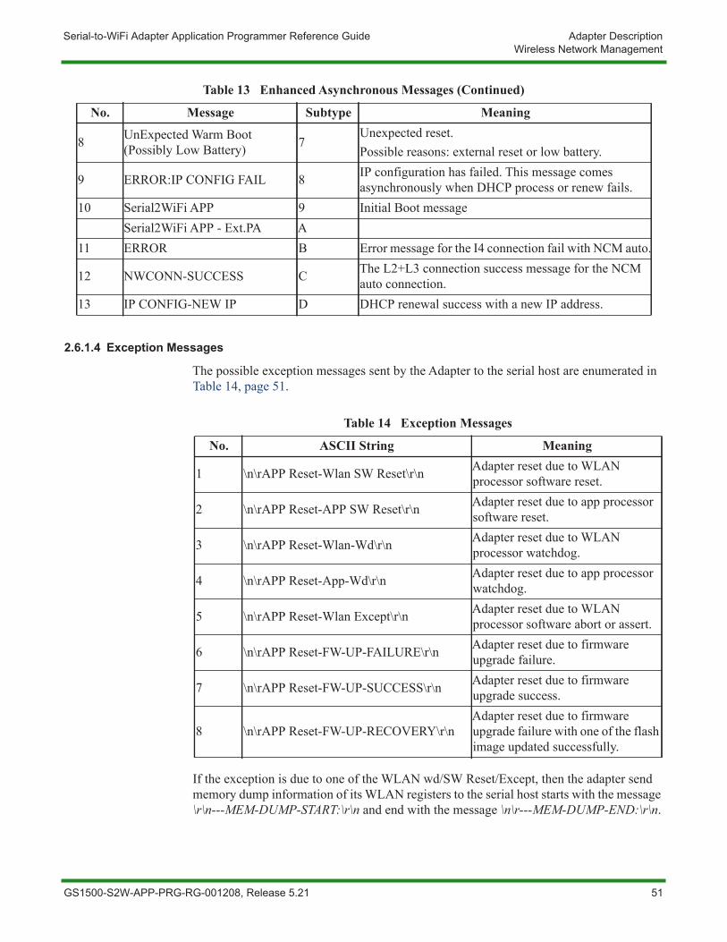
Serial-to-WiFi Adapter Application Programmer Reference Guide Adapter DescriptionWireless Network Management
2.6.1.4 Exception Messages
The possible exception messages sent by the Adapter to the serial host are enumerated in Table 14, page 51.
If the exception is due to one of the WLAN wd/SW Reset/Except, then the adapter send memory dump information of its WLAN registers to the serial host starts with the message \r\n---MEM-DUMP-START:\r\n and end with the message \n\r---MEM-DUMP-END:\r\n.
8 UnExpected Warm Boot (Possibly Low Battery) 7
Unexpected reset. Possible reasons: external reset or low battery.
9 ERROR:IP CONFIG FAIL 8 IP configuration has failed. This message comes asynchronously when DHCP process or renew fails.
10 Serial2WiFi APP 9 Initial Boot messageSerial2WiFi APP - Ext.PA A
11 ERROR B Error message for the I4 connection fail with NCM auto.
12 NWCONN-SUCCESS C The L2+L3 connection success message for the NCM auto connection.
13 IP CONFIG-NEW IP D DHCP renewal success with a new IP address.
Table 13 Enhanced Asynchronous Messages (Continued)
No. Message Subtype Meaning
Table 14 Exception Messages
No. ASCII String Meaning
1 \n\rAPP Reset-Wlan SW Reset\r\n Adapter reset due to WLAN processor software reset.
2 \n\rAPP Reset-APP SW Reset\r\n Adapter reset due to app processor software reset.
3 \n\rAPP Reset-Wlan-Wd\r\n Adapter reset due to WLAN processor watchdog.
4 \n\rAPP Reset-App-Wd\r\n Adapter reset due to app processor watchdog.
5 \n\rAPP Reset-Wlan Except\r\n Adapter reset due to WLAN processor software abort or assert.
6 \n\rAPP Reset-FW-UP-FAILURE\r\n Adapter reset due to firmware upgrade failure.
7 \n\rAPP Reset-FW-UP-SUCCESS\r\n Adapter reset due to firmware upgrade success.
8 \n\rAPP Reset-FW-UP-RECOVERY\r\nAdapter reset due to firmware upgrade failure with one of the flash image updated successfully.
GS1500-S2W-APP-PRG-RG-001208, Release 5.21 51
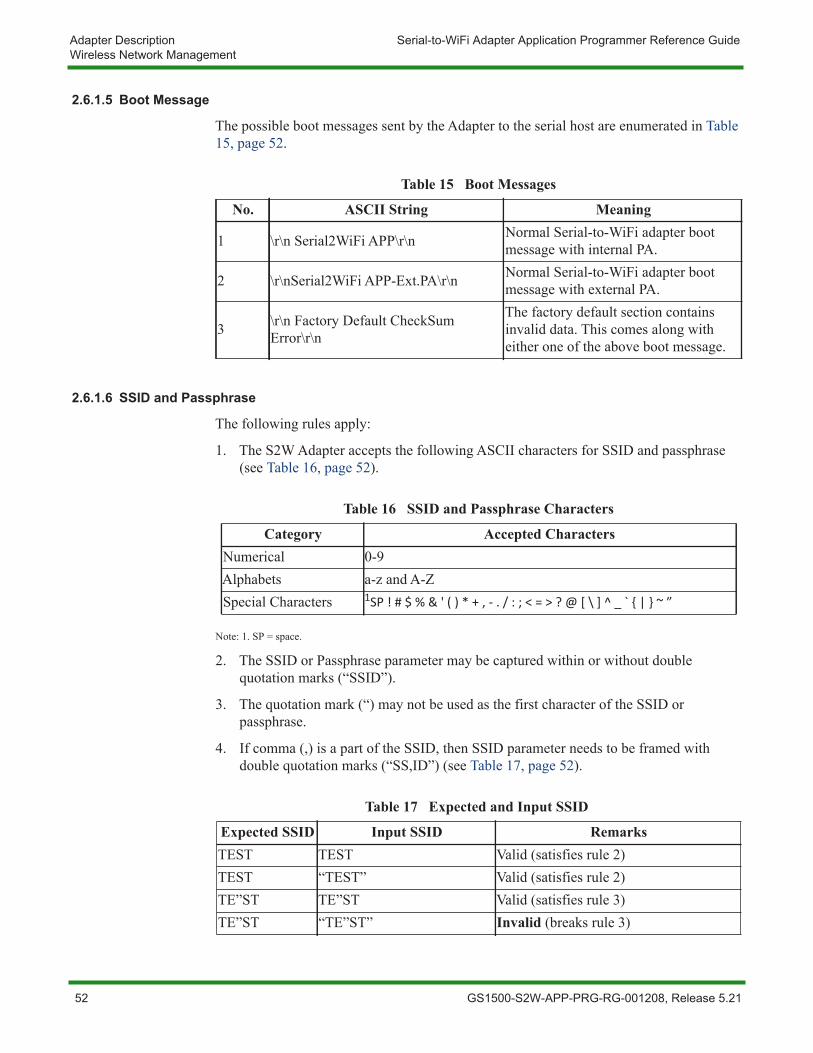
Adapter Description Serial-to-WiFi Adapter Application Programmer Reference GuideWireless Network Management
2.6.1.5 Boot Message
The possible boot messages sent by the Adapter to the serial host are enumerated in Table 15, page 52.
2.6.1.6 SSID and Passphrase
The following rules apply:
1. The S2W Adapter accepts the following ASCII characters for SSID and passphrase (see Table 16, page 52).
Note: 1. SP = space.
2. The SSID or Passphrase parameter may be captured within or without double quotation marks (“SSID”).
3. The quotation mark (“) may not be used as the first character of the SSID or passphrase.
4. If comma (,) is a part of the SSID, then SSID parameter needs to be framed with double quotation marks (“SS,ID”) (see Table 17, page 52).
Table 15 Boot Messages
No. ASCII String Meaning
1 \r\n Serial2WiFi APP\r\n Normal Serial-to-WiFi adapter boot message with internal PA.
2 \r\nSerial2WiFi APP-Ext.PA\r\n Normal Serial-to-WiFi adapter boot message with external PA.
3 \r\n Factory Default CheckSum Error\r\n
The factory default section contains invalid data. This comes along with either one of the above boot message.
Table 16 SSID and Passphrase Characters
Category Accepted CharactersNumerical 0-9Alphabets a-z and A-ZSpecial Characters 1SP ! # $ % & ' ( ) * + , - . / : ; < = > ? @ [ \ ] ^ _ ` { | } ~ ”
Table 17 Expected and Input SSID
Expected SSID Input SSID RemarksTEST TEST Valid (satisfies rule 2)TEST “TEST” Valid (satisfies rule 2)TE”ST TE”ST Valid (satisfies rule 3)TE”ST “TE”ST” Invalid (breaks rule 3)
52 GS1500-S2W-APP-PRG-RG-001208, Release 5.21

Serial-to-WiFi Adapter Application Programmer Reference Guide Adapter DescriptionWireless Network Management
TE,ST “TE,ST” Valid (satisfies rule 4)TE,ST TES,T Invalid (breaks rule 4)TE,S”T “TE,S”T” Invalid (breaks rule 3 and 4)
Table 17 Expected and Input SSID (Continued)
Expected SSID Input SSID Remarks
GS1500-S2W-APP-PRG-RG-001208, Release 5.21 53

Adapter Description Serial-to-WiFi Adapter Application Programmer Reference GuideWireless Network Management
54 GS1500-S2W-APP-PRG-RG-001208, Release 5.21
Chapter 3 Commands for Command Processing Mode
This chapter provides the GainSpan® AT Serial-to-WiFi commands used to configure and view system effects.
The following AT commands are described in this chapter:
• Command Interface, page 58
• UART Interface Configuration, page 60
• SPI Configuration, page 63
• Serial-to-WiFi Configuration, page 64
• Identification Information, page 68
• Serial-to-WiFi Profile Configuration, page 68
• WiFi Interface Configuration, page 74
• WiFi Security Configuration, page 101
• Network Interface, page 134
• Connection Management Configuration, page 163
• GSLINK, page 189
GS1500-S2W-APP-PRG-RG-001208, Release 5.21 55

Commands for Command Processing Mode Serial-to-WiFi Adapter Application Programmer Reference Guide
The following AT commands are described in this chapter (cont.):
• Power State Management, page 202
• Auto Connection, page 208
• Network Connection Manager (NCM), page 214
• Roaming, page 221
• Provisioning, page 222
• RF Tests, page 228
• Miscellaneous, page 235
• GS1500M WiFi Direct (P2P) Commands, page 252
56 GS1500-S2W-APP-PRG-RG-001208, Release 5.21
Serial-to-WiFi Adapter Application Programmer Reference Guide Commands for Command Processing ModeOverview
3.1 OverviewFormatting and processing of commands is described in Command Processing Mode. Parameters are generally ASCII characters. For example, ATEn with n=1 is the series of ASCII characters ‘A’, ‘T’, ‘E’, and ‘1’. Where some parameters are optional, mandatory parameters are denoted by < > and optional parameters by [ ]. If a parameter is mandatory, any associated sub-parameters are also mandatory; sub-parameters of an optional parameter are optional. Parameters must always be provided in the order given in the command description. When an optional parameter is not supplied, the comma delimiters must still be included in the command. Every command starts with the characters “AT”; any other initial characters will cause an error to be returned.
Command Response: In most cases, valid commands return the characters OK if verbose mode is enabled and 0 verbose mode is not enabled. Invalid inputs return ERROR:INVALID INPUT if verbose is enabled and 2 if it is not. Exceptions to this rule are noted explicitly below.
GS1500-S2W-APP-PRG-RG-001208, Release 5.21 57
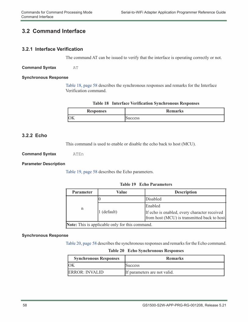
Commands for Command Processing Mode Serial-to-WiFi Adapter Application Programmer Reference GuideCommand Interface
3.2 Command Interface
3.2.1 Interface VerificationThe command AT can be issued to verify that the interface is operating correctly or not.
Command Syntax AT
Synchronous Response
Table 18, page 58 describes the synchronous responses and remarks for the Interface Verification command.
3.2.2 EchoThis command is used to enable or disable the echo back to host (MCU).
Command Syntax ATEn
Parameter Description
Table 19, page 58 describes the Echo parameters.
Synchronous Response
Table 20, page 58 describes the synchronous responses and remarks for the Echo command.
Table 18 Interface Verification Synchronous Responses
Responses RemarksOK Success
Table 19 Echo Parameters
Parameter Value Description
n
0 Disabled
1 (default)EnabledIf echo is enabled, every character received from host (MCU) is transmitted back to host.
Note: This is applicable only for this command.
Table 20 Echo Synchronous Responses
Synchronous Responses RemarksOK SuccessERROR: INVALID If parameters are not valid.
58 GS1500-S2W-APP-PRG-RG-001208, Release 5.21
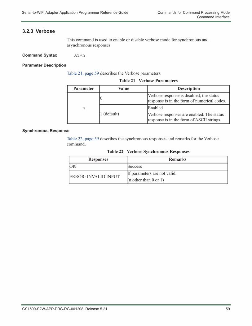
Serial-to-WiFi Adapter Application Programmer Reference Guide Commands for Command Processing ModeCommand Interface
3.2.3 VerboseThis command is used to enable or disable verbose mode for synchronous and asynchronous responses.
Command Syntax ATVn
Parameter Description
Table 21, page 59 describes the Verbose parameters.
Synchronous Response
Table 22, page 59 describes the synchronous responses and remarks for the Verbose command.
Table 21 Verbose Parameters
Parameter Value Description
n
0 Verbose response is disabled, the status response is in the form of numerical codes.
1 (default)EnabledVerbose responses are enabled. The status response is in the form of ASCII strings.
Table 22 Verbose Synchronous Responses
Responses RemarksOK Success
ERROR: INVALID INPUTIf parameters are not valid.(n other than 0 or 1)
GS1500-S2W-APP-PRG-RG-001208, Release 5.21 59
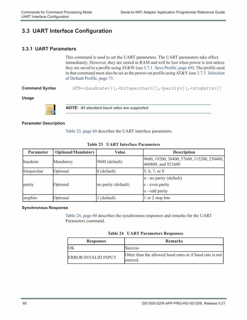
Commands for Command Processing Mode Serial-to-WiFi Adapter Application Programmer Reference GuideUART Interface Configuration
3.3 UART Interface Configuration
3.3.1 UART ParametersThis command is used to set the UART parameters. The UART parameters take effect immediately. However, they are stored in RAM and will be lost when power is lost unless they are saved to a profile using AT&W (see 3.7.1 Save Profile, page 69). The profile used in that command must also be set as the power-on profile using AT&Y (see 3.7.3 Selection of Default Profile, page 71.
Command Syntax ATB=<baudrate>[[,<bitsperchar>][,<parity>][,<stopbits>]]
Usage
Parameter Description
Table 23, page 60 describes the UART interface parameters.
Synchronous Response
Table 24, page 60 describes the synchronous responses and remarks for the UART Parameters command.
NOTE: All standard baud rates are supported.
Table 23 UART Interface Parameters
Parameter Optional/Mandatory Value Description
baudrate Mandatory 9600 (default) 9600, 19200, 38400, 57600, 115200, 230400, 460800, and 921600
bitsperchar Optional 8 (default) 5, 6, 7, or 8
parity Optional no parity (default)n - no parity (default)e - even parityo - odd parity
stopbits Optional 1 (default) 1 or 2 stop bits
Table 24 UART Parameters Responses
Responses RemarksOK Success
ERROR:INVALID INPUT Other than the allowed baud rates or if baud rate is not entered.
60 GS1500-S2W-APP-PRG-RG-001208, Release 5.21
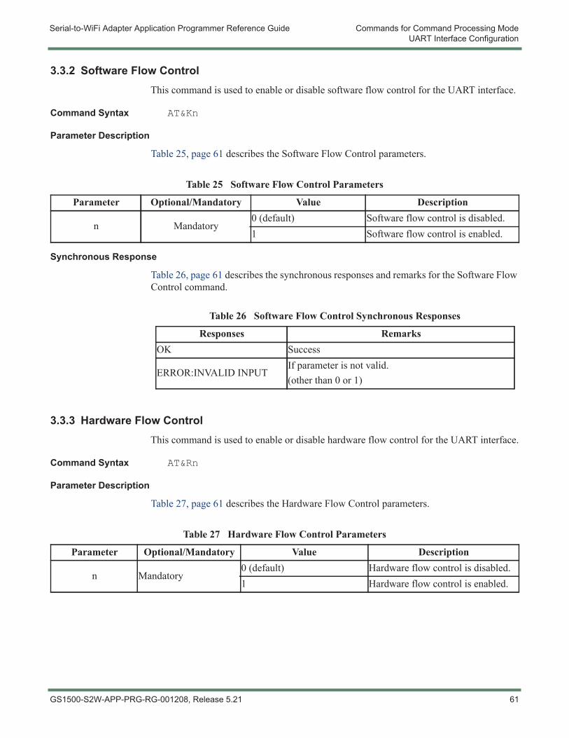
Serial-to-WiFi Adapter Application Programmer Reference Guide Commands for Command Processing ModeUART Interface Configuration
3.3.2 Software Flow ControlThis command is used to enable or disable software flow control for the UART interface.
Command Syntax AT&Kn
Parameter Description
Table 25, page 61 describes the Software Flow Control parameters.
Synchronous Response
Table 26, page 61 describes the synchronous responses and remarks for the Software Flow Control command.
3.3.3 Hardware Flow ControlThis command is used to enable or disable hardware flow control for the UART interface.
Command Syntax AT&Rn
Parameter Description
Table 27, page 61 describes the Hardware Flow Control parameters.
Table 25 Software Flow Control Parameters
Parameter Optional/Mandatory Value Description
n Mandatory0 (default) Software flow control is disabled.1 Software flow control is enabled.
Table 26 Software Flow Control Synchronous Responses
Responses RemarksOK Success
ERROR:INVALID INPUTIf parameter is not valid.(other than 0 or 1)
Table 27 Hardware Flow Control Parameters
Parameter Optional/Mandatory Value Description
n Mandatory0 (default) Hardware flow control is disabled.1 Hardware flow control is enabled.
GS1500-S2W-APP-PRG-RG-001208, Release 5.21 61
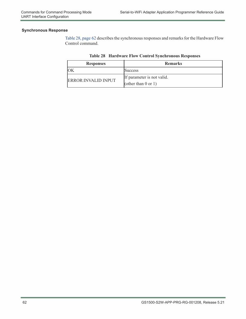
Commands for Command Processing Mode Serial-to-WiFi Adapter Application Programmer Reference GuideUART Interface Configuration
Synchronous Response
Table 28, page 62 describes the synchronous responses and remarks for the Hardware Flow Control command.
Table 28 Hardware Flow Control Synchronous Responses
Responses RemarksOK Success
ERROR:INVALID INPUTIf parameter is not valid.(other than 0 or 1)
62 GS1500-S2W-APP-PRG-RG-001208, Release 5.21
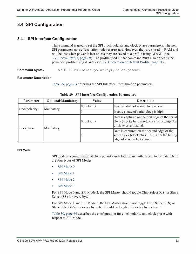
Serial-to-WiFi Adapter Application Programmer Reference Guide Commands for Command Processing ModeSPI Configuration
3.4 SPI Configuration
3.4.1 SPI Interface ConfigurationThis command is used to set the SPI clock polarity and clock phase parameters. The new SPI parameters take effect after node reset/restart. However, they are stored in RAM and will be lost when power is lost unless they are saved to a profile using AT&W (see 3.7.1 Save Profile, page 69). The profile used in that command must also be set as the power-on profile using AT&Y (see 3.7.3 Selection of Default Profile, page 71).
Command Syntax AT+SPICONF=<clockpolarity>,<clockphase>
Parameter Description
Table 29, page 63 describes the SPI Interface Configuration parameters.
SPI Mode
SPI mode is a combination of clock polarity and clock phase with respect to the data. There are four types of SPI Modes:
• SPI Mode 0
• SPI Mode 1
• SPI Mode 2
• SPI Mode 3
For SPI Mode 0 and SPI Mode 2, the SPI Master should toggle Chip Select (CS) or Slave Select (SS) for every byte.
For SPI Mode 1 and SPI Mode 3, the SPI Master should not toggle Chip Select (CS) or Slave Select (SS) for every byte; but should be toggled for every byte stream.
Table 30, page 64 describes the configuration for clock polarity and clock phase with respect to SPI Mode.
Table 29 SPI Interface Configuration Parameters
Parameter Optional/Mandatory Value Description
clockpolarity Mandatory0 (default) Inactive state of serial clock is low.1 Inactive state of serial clock is high.
clockphase Mandatory
0 (default)Data is captured on the first edge of the serial clock (clock phase zero), after the falling edge of slave select signal.
1Data is captured on the second edge of the serial clock (clock phase 180), after the falling edge of slave select signal.
GS1500-S2W-APP-PRG-RG-001208, Release 5.21 63
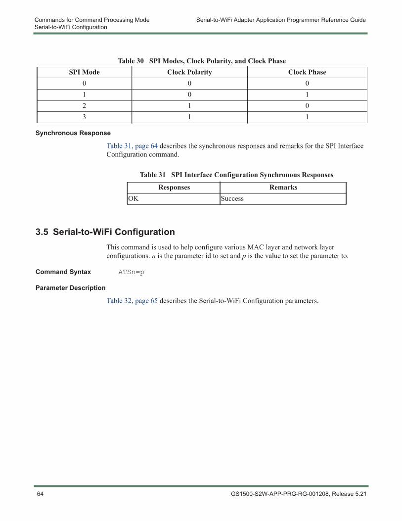
Commands for Command Processing Mode Serial-to-WiFi Adapter Application Programmer Reference GuideSerial-to-WiFi Configuration
Synchronous Response
Table 31, page 64 describes the synchronous responses and remarks for the SPI Interface Configuration command.
3.5 Serial-to-WiFi ConfigurationThis command is used to help configure various MAC layer and network layer configurations. n is the parameter id to set and p is the value to set the parameter to.
Command Syntax ATSn=p
Parameter Description
Table 32, page 65 describes the Serial-to-WiFi Configuration parameters.
Table 30 SPI Modes, Clock Polarity, and Clock PhaseSPI Mode Clock Polarity Clock Phase
0 0 01 0 12 1 03 1 1
Table 31 SPI Interface Configuration Synchronous Responses
Responses RemarksOK Success
64 GS1500-S2W-APP-PRG-RG-001208, Release 5.21
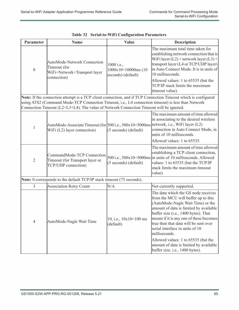
Serial-to-WiFi Adapter Application Programmer Reference Guide Commands for Command Processing ModeSerial-to-WiFi Configuration
Table 32 Serial-to-WiFi Configuration Parameters
Parameter Name Value Description
0
AutoMode-Network Connection Timeout (for WiFi+Network+Transport layer connection)
1000 i.e., 1000x10=10000ms (10 seconds) (default)
The maximum total time taken for establishing network connection that is WiFi layer (L2) + network layer (L3) + transport layer (L4 or TCP/UDP layer) in Auto Connect Mode. It is in units of 10 milliseconds.Allowed values: 1 to 65535 (but the TCP/IP stack limits the maximum timeout value).
Note: If the connection attempt is a TCP client connection, and if TCP Connection Timeout which is configured using ATS2 (Command Mode-TCP Connection Timeout, i.e., L4 connection timeout) is less than Network Connection Timeout (L2+L3+L4). The value of Network Connection Timeout will be ignored.
1 AutoMode-Associate Timeout (for WiFi (L2) layer connection)
500 i.e., 500x10=5000ms (5 seconds) (default)
The maximum amount of time allowed in associating to the desired wireless network, i.e., WiFi layer (L2) connection in Auto Connect Mode, in units of 10 milliseconds.Allowed values: 1 to 65535.
2CommandMode-TCP Connection Timeout (for Transport layer or TCP/UDP connection)
500 i.e., 500x10=5000ms (5 seconds) (default)
The maximum amount of time allowed establishing a TCP client connection, in units of 10 milliseconds. Allowed values: 1 to 65535 (but the TCP/IP stack limits the maximum timeout value).
Note: 0 corresponds to the default TCP/IP stack timeout (75 seconds).3 Association Retry Count N/A Not currently supported.
4 AutoMode-Nagle Wait Time 10, i.e., 10x10=100 ms (default)
The data which the GS node receives from the MCU will buffer up to this (AutoMode-Nagle Wait Time) or the amount of data is limited by available buffer size (i.e., 1400 bytes). That means if it is any one of these becomes true then that data will be sent over serial interface in units of 10 milliseconds. Allowed values: 1 to 65535 (but the amount of data is limited by available buffer size, i.e., 1400 bytes).
GS1500-S2W-APP-PRG-RG-001208, Release 5.21 65
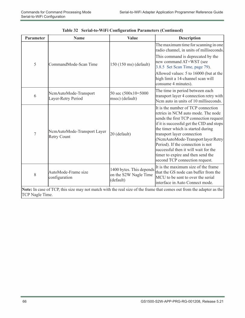
Commands for Command Processing Mode Serial-to-WiFi Adapter Application Programmer Reference GuideSerial-to-WiFi Configuration
5 CommandMode-Scan Time 150 (150 ms) (default)
The maximum time for scanning in one radio channel, in units of milliseconds.This command is deprecated by the new command AT+WST (see 3.8.5 Set Scan Time, page 79).Allowed values: 5 to 16000 (but at the high limit a 14-channel scan will consume 4 minutes).
6 NcmAutoMode-Transport Layer-Retry Period
50 sec (500x10=5000 msec) (default)
The time in period between each transport layer 4 connection retry with Ncm auto in units of 10 milliseconds.
7 NcmAutoMode-Transport Layer Retry Count 20 (default)
It is the number of TCP connection retries in NCM auto mode. The node sends the first TCP connection request if it is successful get the CID and stops the timer which is started during transport layer connection (NcmAutoMode-Transport layer Retry Period). If the connection is not successful then it will wait for the timer to expire and then send the second TCP connection request.
8 AutoMode-Frame size configuration
1400 bytes. This depends on the S2W Nagle Time (default)
It is the maximum size of the frame that the GS node can buffer from the MCU to be sent to over the serial interface in Auto Connect mode.
Note: In case of TCP, this size may not match with the real size of the frame that comes out from the adapter as the TCP Nagle Time.
Table 32 Serial-to-WiFi Configuration Parameters (Continued)
Parameter Name Value Description
66 GS1500-S2W-APP-PRG-RG-001208, Release 5.21
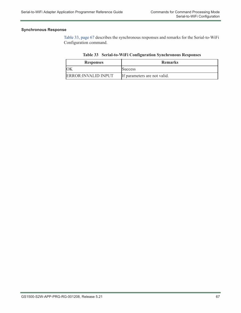
Serial-to-WiFi Adapter Application Programmer Reference Guide Commands for Command Processing ModeSerial-to-WiFi Configuration
Synchronous Response
Table 33, page 67 describes the synchronous responses and remarks for the Serial-to-WiFi Configuration command.
Table 33 Serial-to-WiFi Configuration Synchronous Responses
Responses RemarksOK SuccessERROR:INVALID INPUT If parameters are not valid.
GS1500-S2W-APP-PRG-RG-001208, Release 5.21 67
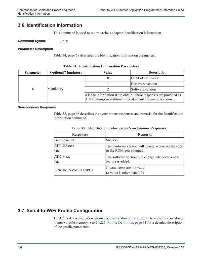
Commands for Command Processing Mode Serial-to-WiFi Adapter Application Programmer Reference GuideIdentification Information
3.6 Identification InformationThis command is used to return various adapter identification information.
Command Syntax ATIn
Parameter Description
Table 34, page 68 describes the Identification Information parameters.
Synchronous Response
Table 35, page 68 describes the synchronous responses and remarks for the Identification Information command.
3.7 Serial-to-WiFi Profile ConfigurationThe GS node configuration parameters can be stored in a profile. These profiles are stored in non-volatile memory. See 2.1.2.1 Profile Definition, page 31 for a detailed description of the profile parameters.
Table 34 Identification Information Parameters
Parameter Optional/Mandatory Value Description
n Mandatory
0 OEM identification1 Hardware version2 Software version
n is the information ID to obtain. These responses are provided as ASCII strings in addition to the standard command response.
Table 35 Identification Information Synchronous Responses
Responses RemarksGainSpan OK SuccessATI1:GSxxxxOK
The hardware version will change whenever the code in the ROM gets changed.
ATI2:x.x.xOK
The software version will change whenever a new feature is added.
ERROR:INVALID INPUTIf parameters are not valid.(n value is other than 0-2)
68 GS1500-S2W-APP-PRG-RG-001208, Release 5.21
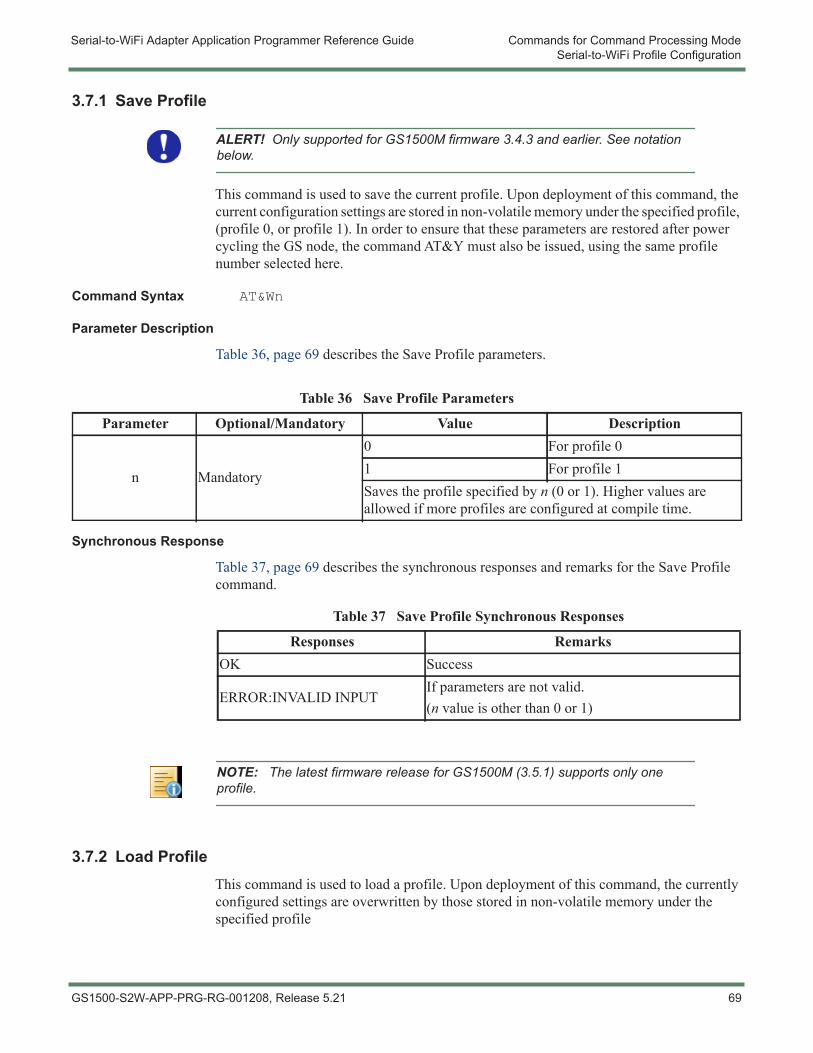
Serial-to-WiFi Adapter Application Programmer Reference Guide Commands for Command Processing ModeSerial-to-WiFi Profile Configuration
3.7.1 Save Profile
This command is used to save the current profile. Upon deployment of this command, the current configuration settings are stored in non-volatile memory under the specified profile, (profile 0, or profile 1). In order to ensure that these parameters are restored after power cycling the GS node, the command AT&Y must also be issued, using the same profile number selected here.
Command Syntax AT&Wn
Parameter Description
Table 36, page 69 describes the Save Profile parameters.
Synchronous Response
Table 37, page 69 describes the synchronous responses and remarks for the Save Profile command.
3.7.2 Load ProfileThis command is used to load a profile. Upon deployment of this command, the currently configured settings are overwritten by those stored in non-volatile memory under the specified profile
ALERT! Only supported for GS1500M firmware 3.4.3 and earlier. See notation below.
Table 36 Save Profile Parameters
Parameter Optional/Mandatory Value Description
n Mandatory
0 For profile 01 For profile 1Saves the profile specified by n (0 or 1). Higher values are allowed if more profiles are configured at compile time.
Table 37 Save Profile Synchronous Responses
Responses RemarksOK Success
ERROR:INVALID INPUTIf parameters are not valid.(n value is other than 0 or 1)
NOTE: The latest firmware release for GS1500M (3.5.1) supports only one profile.
GS1500-S2W-APP-PRG-RG-001208, Release 5.21 69
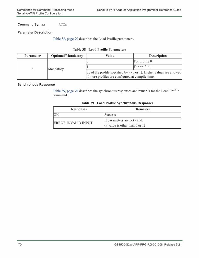
Commands for Command Processing Mode Serial-to-WiFi Adapter Application Programmer Reference GuideSerial-to-WiFi Profile Configuration
Command Syntax ATZn
Parameter Description
Table 38, page 70 describes the Load Profile parameters.
Synchronous Response
Table 39, page 70 describes the synchronous responses and remarks for the Load Profile command.
Table 38 Load Profile Parameters
Parameter Optional/Mandatory Value Description
n Mandatory
0 For profile 01 For profile 1Load the profile specified by n (0 or 1). Higher values are allowed if more profiles are configured at compile time.
Table 39 Load Profile Synchronous Responses
Responses RemarksOK Success
ERROR:INVALID INPUTIf parameters are not valid.(n value is other than 0 or 1)
70 GS1500-S2W-APP-PRG-RG-001208, Release 5.21
Serial-to-WiFi Adapter Application Programmer Reference Guide Commands for Command Processing ModeSerial-to-WiFi Profile Configuration
3.7.3 Selection of Default Profile
This command is used to select the default profile. The settings from the profile that are chosen as the default profile are loaded from non-volatile memory when the device is started.
Command Syntax AT&Yn
Parameter Description
Table 40, page 71 describes the Selection of Default Profile parameters.
Synchronous Response
Table 41, page 71 describes the synchronous responses and remarks for the Selection of Default Profile command.
Example AT&Y0OK
ALERT! Only supported for GS1500M firmware release 3.4.3 and earlier.
Table 40 Selection of Default Profile Parameters
Parameter Optional/Mandatory Value Description
n Mandatory
0 For profile 01 For profile 1Set default profile to the value n (0 or 1). Higher values are allowed if more profiles are configured at compile time.
Table 41 Selection of Default Profile Synchronous Responses
Responses RemarksOK Success
ERROR:INVALID INPUTIf parameters are not valid.(n value is other than 0 or 1)
NOTE: The latest firmware release for GS1500M (3.5.1 or later) supports only one profile.
GS1500-S2W-APP-PRG-RG-001208, Release 5.21 71
Commands for Command Processing Mode Serial-to-WiFi Adapter Application Programmer Reference GuideSerial-to-WiFi Profile Configuration
3.7.4 Restore to Factory DefaultsThis command is used to restore current profile to factory default values. The factory default values are stored in RAM, and will be lost after each power cycle.
Upon deployment of this command, the current configuration variables are reset to the factory defaults. These defaults are defined by macro values in the configuration header, and can be modified at compile time. Issuing this command resets essentially all configuration variables except the IEEE MAC address. Only the command AT+NMAC (see 3.8.1 Set MAC Address, page 74) changes the MAC address.
Command Syntax AT&F
Synchronous Response
Table 42, page 72 describes the synchronous responses and remarks for the Restore to Factory Defaults command.
Table 42 Restore to Factory Defaults Synchronous Responses
Responses RemarksOK Success
72 GS1500-S2W-APP-PRG-RG-001208, Release 5.21
Serial-to-WiFi Adapter Application Programmer Reference Guide Commands for Command Processing ModeSerial-to-WiFi Profile Configuration
3.7.5 Output Current ConfigurationThis command is used to output the configuration of current and saved profile parameter values in ASCII. The details of the profile parameters are described in 2.1.2.1 Profile Definition, page 31.
Command Syntax AT&V
Synchronous Response
Table 43, page 73 describes the synchronous responses and remarks for the Output Current Configuration command.
Table 43 Output Current Configuration Synchronous Responses
Responses RemarksACTIVE PROFILEC0 &Y0 E1 V1 B=9600,8,N,1 &K0 &R0+NDHCP=0 +NSET=192.168.1.99,255.255.255.0,192.168.1.1+DNS1=0.0.0.0, +DNS2=0.0.0.0+WM=0 +WAUTO=0,"GSDemoKit",,6+WRETRY=5 +WP=0 +WRXPS=1 +WRXACTIVE=0+NAUTO=0,1,192.168.1.1,8+WAUTH=0 +WWPA="Serial2Wifi"+PSK-valid=0 +SSID=+WWEP1=1234567890 +WWEP2=+WWEP3= +WWEP4=S0=01000 S1=00500 S2=00500 S3=00003 S4=00010 S5=00150 S6=00050 S7=00020 S8=01400+BDATA=0 +WSEC=0 +ASYNCMSG=0
Success
The number of profiles depends upon the default configuration of the module.
STORED PROFILE 0E1 V1 B=9600,8,N,1 &K0 &R0+NDHCP=0 +NSET=192.168.1.99,255.255.255.0,192.168.1.1+DNS1=0.0.0.0, +DNS2=0.0.0.0+WM=0 +WAUTO=0,"GSDemoKit",,6+WRETRY=5 +WP=0 +WRXPS=1 +WRXACTIVE=0+NAUTO=0,1,192.168.1.1,8+WAUTH=0 +WWPA="Serial2Wifi"+PSK-valid=0 +SSID=+WWEP1=1234567890 +WWEP2=+WWEP3= +WWEP4=S0=01000 S1=00500 S2=00500 S3=00003 S4=00010 S5=00150 S6=00050 S7=00020 S8=01400+BDATA=0+WSEC=0+ASYNCMSG=0OK
Success
GS1500-S2W-APP-PRG-RG-001208, Release 5.21 73
Commands for Command Processing Mode Serial-to-WiFi Adapter Application Programmer Reference GuideWiFi Interface Configuration
3.8 WiFi Interface Configuration
3.8.1 Set MAC AddressThis command is used to set the MAC address to the GS node.
The MAC address is used in the 802.11 protocol to identify the various nodes communicating with an Access Point and to route messages within the local area (layer 2) network. Fixed MAC addresses issued to network interfaces are hierarchically structured and are intended to be globally unique. Before issuing a MAC address to a given Adapter, ensure that no other local device is using that address.
Command Syntax AT+NMAC=<MAC ADDRESS>
Parameter Description
Table 44, page 74 describes the Selection of Set MAC Address parameters.
Synchronous Response
Table 45, page 74 describes the synchronous responses and remarks for the Set MAC Address command.
Example AT+NMAC=00:1d:c9:d0:70:ccOK
AT+NMAC=?00:1d:c9:d0:70:ccOK
Table 44 Set MAC Address Parameters
Parameter Optional/Mandatory Value Description
MAC Address Mandatory xx:xx:xx:xx:xx:xx(17 characters)
The format of the MAC address is a 17 character colon-delimited hexadecimal number. The MAC address supplied is saved to Flash memory, and will be used on each subsequent cold boot (from power Off) or warm boot (from Standby).
Table 45 Set MAC Address Synchronous Responses
Responses RemarksOK SuccessERROR:INVALID INPUT If value is not in the valid format.
74 GS1500-S2W-APP-PRG-RG-001208, Release 5.21
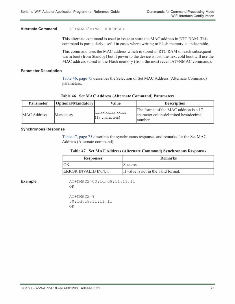
Serial-to-WiFi Adapter Application Programmer Reference Guide Commands for Command Processing ModeWiFi Interface Configuration
Alternate Command AT+NMAC2=<MAC ADDRESS>
This alternate command is used to issue to store the MAC address in RTC RAM. This command is particularly useful in cases where writing to Flash memory is undesirable.
This command uses the MAC address which is stored in RTC RAM on each subsequent warm boot (from Standby) but if power to the device is lost, the next cold boot will use the MAC address stored in the Flash memory (from the most recent AT+NMAC command).
Parameter Description
Table 46, page 75 describes the Selection of Set MAC Address (Alternate Command) parameters.
Synchronous Response
Table 47, page 75 describes the synchronous responses and remarks for the Set MAC Address (Alternate command).
Example AT+NMAC2=00:1d:c9:11:11:11OK
AT+NMAC2=?00:1d:c9:11:11:11OK
Table 46 Set MAC Address (Alternate Command) Parameters
Parameter Optional/Mandatory Value Description
MAC Address Mandatory xx:xx:xx:xx:xx:xx(17 characters)
The format of the MAC address is a 17 character colon-delimited hexadecimal number.
Table 47 Set MAC Address (Alternate Command) Synchronous Responses
Responses RemarksOK SuccessERROR:INVALID INPUT If value is not in the valid format.
GS1500-S2W-APP-PRG-RG-001208, Release 5.21 75
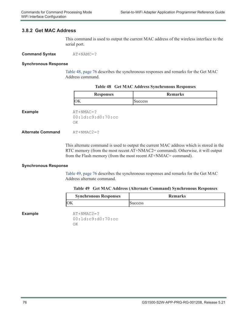
Commands for Command Processing Mode Serial-to-WiFi Adapter Application Programmer Reference GuideWiFi Interface Configuration
3.8.2 Get MAC AddressThis command is used to output the current MAC address of the wireless interface to the serial port.
Command Syntax AT+NAMC=?
Synchronous Response
Table 48, page 76 describes the synchronous responses and remarks for the Get MAC Address command.
Example AT+NMAC=?00:1d:c9:d0:70:ccOK
Alternate Command AT+NMAC2=?
This alternate command is used to output the current MAC address which is stored in the RTC memory (from the most recent AT+NMAC2= command). Otherwise, it will output from the Flash memory (from the most recent AT+NMAC= command).
Synchronous Response
Table 49, page 76 describes the synchronous responses and remarks for the Get MAC Address alternate command.
Example AT+NMAC2=?00:1d:c9:d0:70:ccOK
Table 48 Get MAC Address Synchronous Responses
Responses RemarksOK Success
Table 49 Get MAC Address (Alternate Command) Synchronous Responses
Synchronous Responses RemarksOK Success
76 GS1500-S2W-APP-PRG-RG-001208, Release 5.21
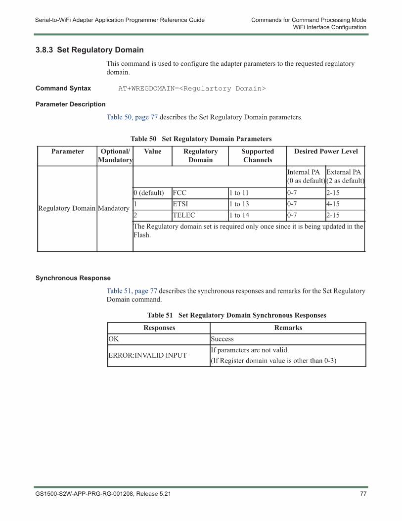
Serial-to-WiFi Adapter Application Programmer Reference Guide Commands for Command Processing ModeWiFi Interface Configuration
3.8.3 Set Regulatory DomainThis command is used to configure the adapter parameters to the requested regulatory domain.
Command Syntax AT+WREGDOMAIN=<Regulartory Domain>
Parameter Description
Table 50, page 77 describes the Set Regulatory Domain parameters.
Synchronous Response
Table 51, page 77 describes the synchronous responses and remarks for the Set Regulatory Domain command.
Table 50 Set Regulatory Domain Parameters
Parameter Optional/Mandatory
Value Regulatory Domain
Supported Channels
Desired Power Level
Regulatory Domain Mandatory
Internal PA (0 as default)
External PA (2 as default)
0 (default) FCC 1 to 11 0-7 2-151 ETSI 1 to 13 0-7 4-152 TELEC 1 to 14 0-7 2-15The Regulatory domain set is required only once since it is being updated in the Flash.
Table 51 Set Regulatory Domain Synchronous Responses
Responses RemarksOK Success
ERROR:INVALID INPUTIf parameters are not valid.(If Register domain value is other than 0-3)
GS1500-S2W-APP-PRG-RG-001208, Release 5.21 77
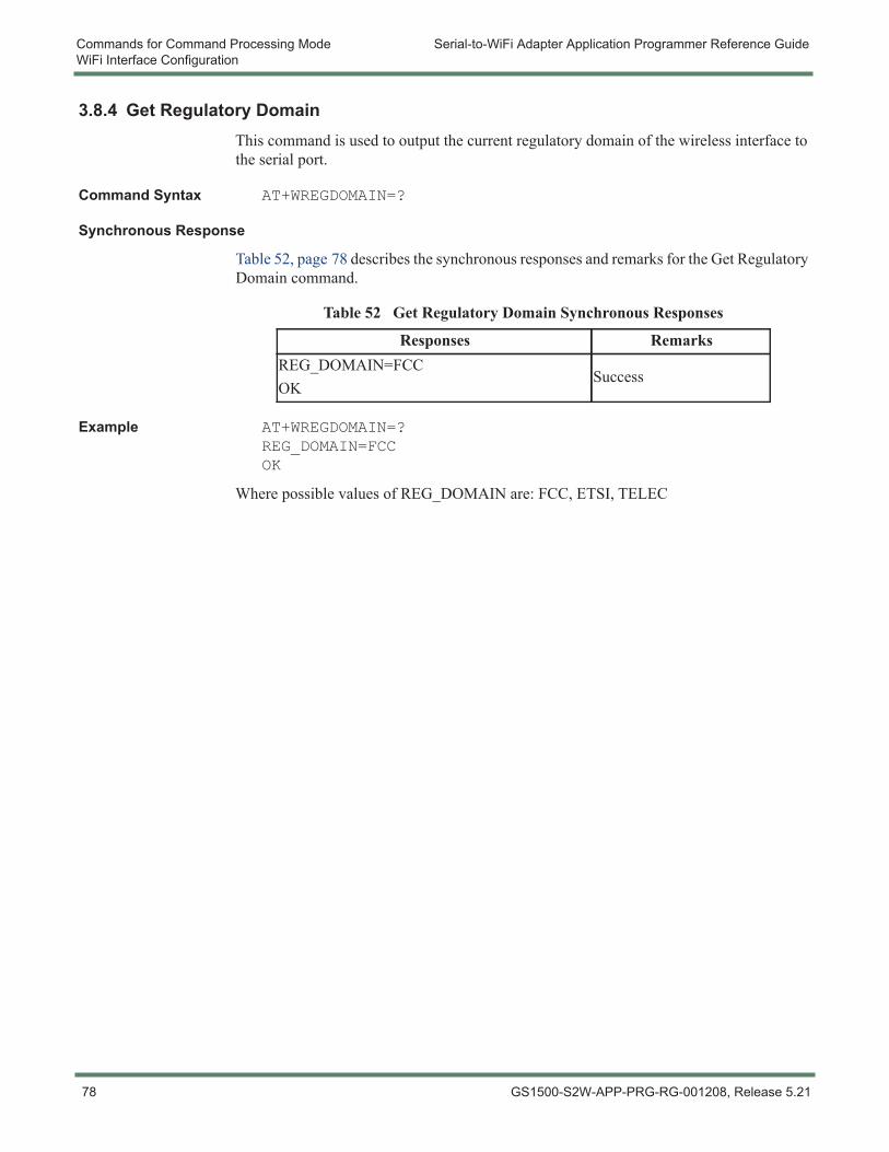
Commands for Command Processing Mode Serial-to-WiFi Adapter Application Programmer Reference GuideWiFi Interface Configuration
3.8.4 Get Regulatory DomainThis command is used to output the current regulatory domain of the wireless interface to the serial port.
Command Syntax AT+WREGDOMAIN=?
Synchronous Response
Table 52, page 78 describes the synchronous responses and remarks for the Get Regulatory Domain command.
Example AT+WREGDOMAIN=?REG_DOMAIN=FCCOK
Where possible values of REG_DOMAIN are: FCC, ETSI, TELEC
Table 52 Get Regulatory Domain Synchronous Responses
Responses RemarksREG_DOMAIN=FCCOK
Success
78 GS1500-S2W-APP-PRG-RG-001208, Release 5.21
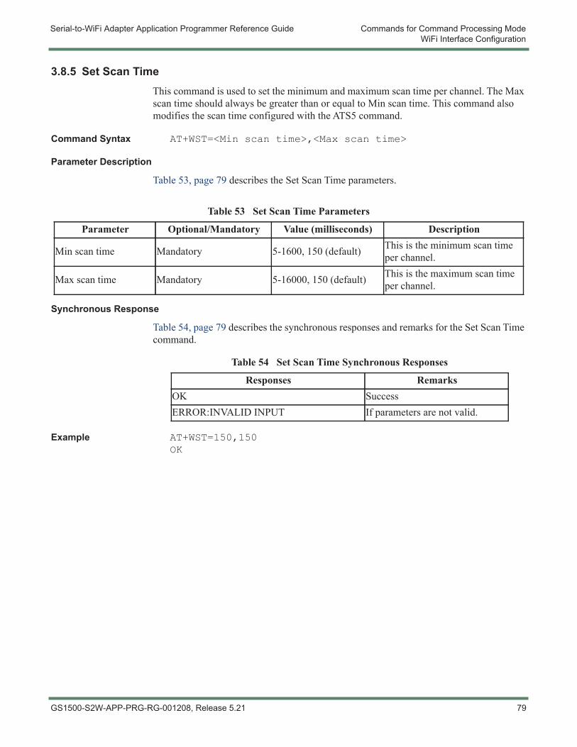
Serial-to-WiFi Adapter Application Programmer Reference Guide Commands for Command Processing ModeWiFi Interface Configuration
3.8.5 Set Scan TimeThis command is used to set the minimum and maximum scan time per channel. The Max scan time should always be greater than or equal to Min scan time. This command also modifies the scan time configured with the ATS5 command.
Command Syntax AT+WST=<Min scan time>,<Max scan time>
Parameter Description
Table 53, page 79 describes the Set Scan Time parameters.
Synchronous Response
Table 54, page 79 describes the synchronous responses and remarks for the Set Scan Time command.
Example AT+WST=150,150OK
Table 53 Set Scan Time Parameters
Parameter Optional/Mandatory Value (milliseconds) Description
Min scan time Mandatory 5-1600, 150 (default) This is the minimum scan time per channel.
Max scan time Mandatory 5-16000, 150 (default) This is the maximum scan time per channel.
Table 54 Set Scan Time Synchronous Responses
Responses RemarksOK SuccessERROR:INVALID INPUT If parameters are not valid.
GS1500-S2W-APP-PRG-RG-001208, Release 5.21 79
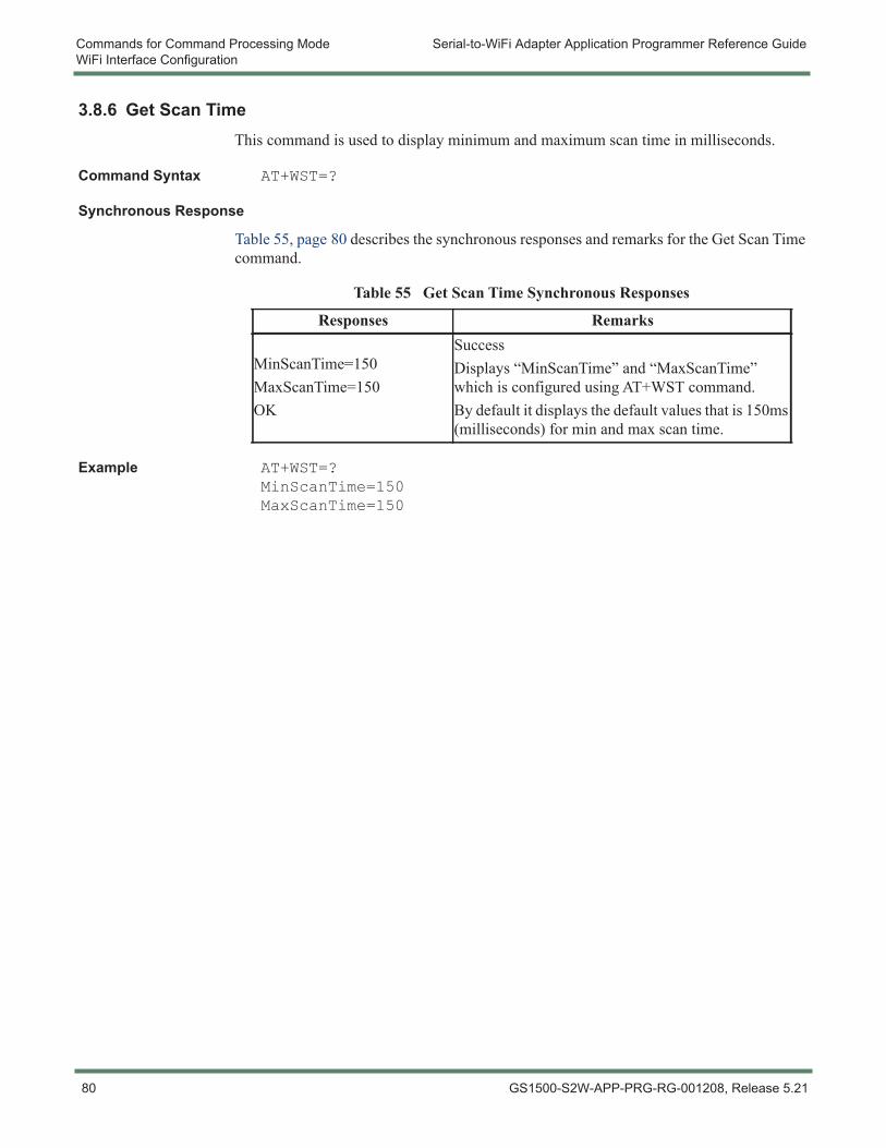
Commands for Command Processing Mode Serial-to-WiFi Adapter Application Programmer Reference GuideWiFi Interface Configuration
3.8.6 Get Scan TimeThis command is used to display minimum and maximum scan time in milliseconds.
Command Syntax AT+WST=?
Synchronous Response
Table 55, page 80 describes the synchronous responses and remarks for the Get Scan Time command.
Example AT+WST=?MinScanTime=150MaxScanTime=150
Table 55 Get Scan Time Synchronous Responses
Responses Remarks
MinScanTime=150MaxScanTime=150OK
SuccessDisplays “MinScanTime” and “MaxScanTime” which is configured using AT+WST command.By default it displays the default values that is 150ms (milliseconds) for min and max scan time.
80 GS1500-S2W-APP-PRG-RG-001208, Release 5.21
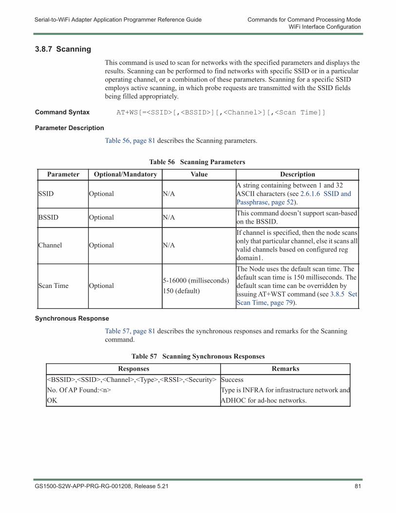
Serial-to-WiFi Adapter Application Programmer Reference Guide Commands for Command Processing ModeWiFi Interface Configuration
3.8.7 ScanningThis command is used to scan for networks with the specified parameters and displays the results. Scanning can be performed to find networks with specific SSID or in a particular operating channel, or a combination of these parameters. Scanning for a specific SSID employs active scanning, in which probe requests are transmitted with the SSID fields being filled appropriately.
Command Syntax AT+WS[=<SSID>[,<BSSID>][,<Channel>][,<Scan Time]]
Parameter Description
Table 56, page 81 describes the Scanning parameters.
Synchronous Response
Table 57, page 81 describes the synchronous responses and remarks for the Scanning command.
Table 56 Scanning Parameters
Parameter Optional/Mandatory Value Description
SSID Optional N/AA string containing between 1 and 32 ASCII characters (see 2.6.1.6 SSID and Passphrase, page 52).
BSSID Optional N/A This command doesn’t support scan-based on the BSSID.
Channel Optional N/A
If channel is specified, then the node scans only that particular channel, else it scans all valid channels based on configured reg domain1.
Scan Time Optional5-16000 (milliseconds)150 (default)
The Node uses the default scan time. The default scan time is 150 milliseconds. The default scan time can be overridden by issuing AT+WST command (see 3.8.5 Set Scan Time, page 79).
Table 57 Scanning Synchronous Responses
Responses Remarks<BSSID>,<SSID>,<Channel>,<Type>,<RSSI>,<Security>No. Of AP Found:<n>OK
SuccessType is INFRA for infrastructure network andADHOC for ad-hoc networks.
GS1500-S2W-APP-PRG-RG-001208, Release 5.21 81
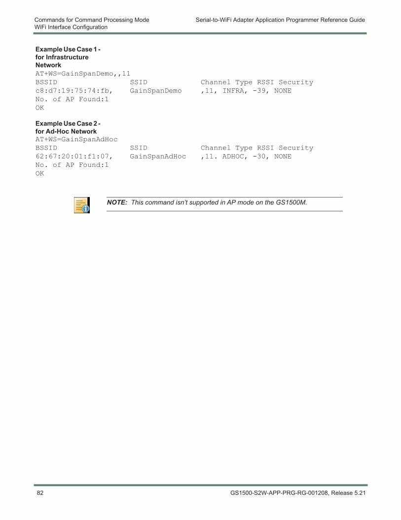
Commands for Command Processing Mode Serial-to-WiFi Adapter Application Programmer Reference GuideWiFi Interface Configuration
Example Use Case 1 - for Infrastructure NetworkAT+WS=GainSpanDemo,,11BSSID SSID Channel Type RSSI Securityc8:d7:19:75:74:fb, GainSpanDemo ,11, INFRA, -39, NONENo. of AP Found:1OK
Example Use Case 2 - for Ad-Hoc NetworkAT+WS=GainSpanAdHocBSSID SSID Channel Type RSSI Security62:67:20:01:f1:07, GainSpanAdHoc ,11. ADHOC, -30, NONENo. of AP Found:1OK
NOTE: This command isn’t supported in AP mode on the GS1500M.
82 GS1500-S2W-APP-PRG-RG-001208, Release 5.21
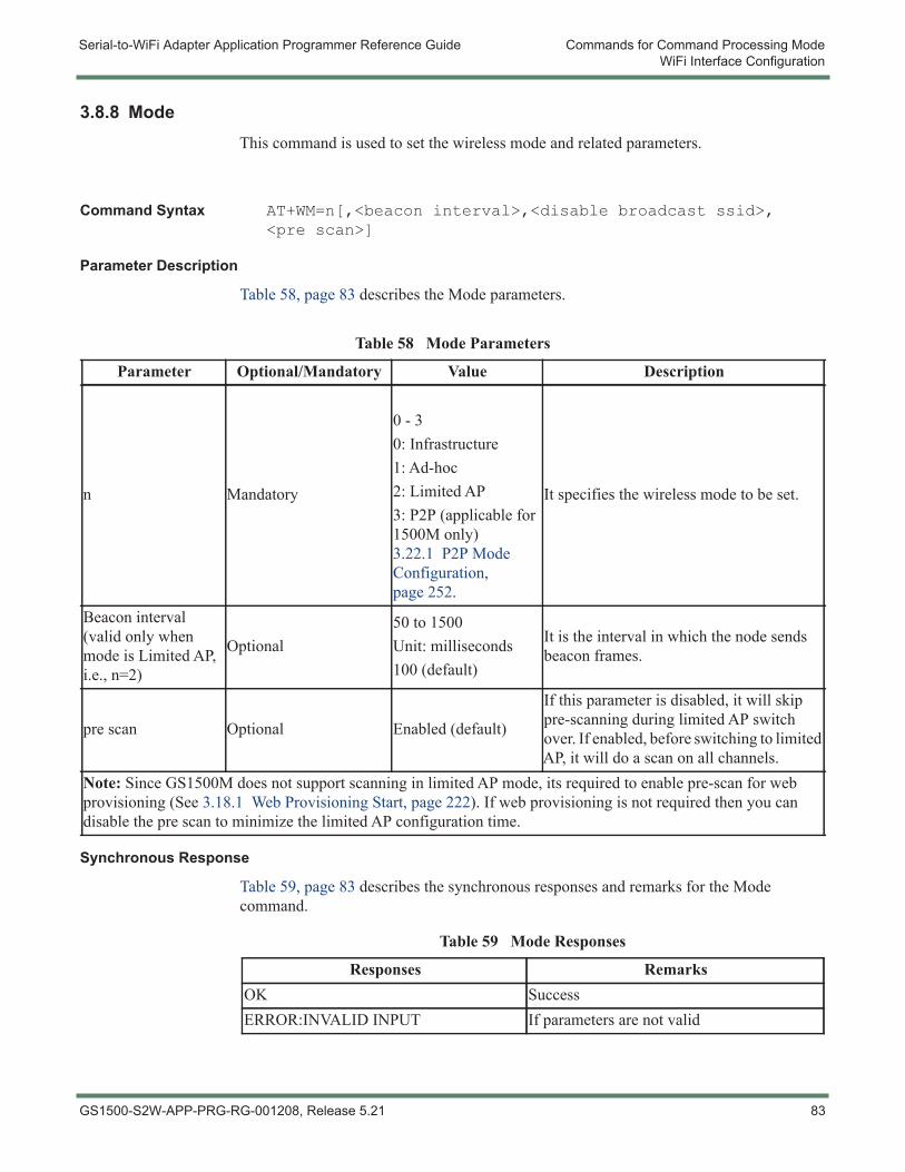
Serial-to-WiFi Adapter Application Programmer Reference Guide Commands for Command Processing ModeWiFi Interface Configuration
3.8.8 ModeThis command is used to set the wireless mode and related parameters.
Command Syntax AT+WM=n[,<beacon interval>,<disable broadcast ssid>,<pre scan>]
Parameter Description
Table 58, page 83 describes the Mode parameters.
Synchronous Response
Table 59, page 83 describes the synchronous responses and remarks for the Mode command.
Table 58 Mode Parameters
Parameter Optional/Mandatory Value Description
n Mandatory
0 - 30: Infrastructure1: Ad-hoc2: Limited AP3: P2P (applicable for 1500M only) 3.22.1 P2P Mode Configuration, page 252.
It specifies the wireless mode to be set.
Beacon interval (valid only when mode is Limited AP, i.e., n=2)
Optional50 to 1500Unit: milliseconds100 (default)
It is the interval in which the node sends beacon frames.
pre scan Optional Enabled (default)
If this parameter is disabled, it will skip pre-scanning during limited AP switch over. If enabled, before switching to limited AP, it will do a scan on all channels.
Note: Since GS1500M does not support scanning in limited AP mode, its required to enable pre-scan for web provisioning (See 3.18.1 Web Provisioning Start, page 222). If web provisioning is not required then you can disable the pre scan to minimize the limited AP configuration time.
Table 59 Mode Responses
Responses RemarksOK SuccessERROR:INVALID INPUT If parameters are not valid
GS1500-S2W-APP-PRG-RG-001208, Release 5.21 83
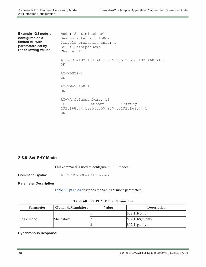
Commands for Command Processing Mode Serial-to-WiFi Adapter Application Programmer Reference GuideWiFi Interface Configuration
Example - GS node is configured as a limited AP with parameters set by the following values
Mode: 2 (Limited AP)Beacon interval: 150msDisable broadcast ssid: 1SSID: GainSpanDemoChannel:11
AT+NSET=192.168.44.1,255.255.255.0,192.168.44.1OK
AT+NDHCP=1OK
AT+WM=2,150,1OK
AT+WA=GainSpanDemo,,11IP Subnet Gateway192.168.44.1:255.255.255.0:192.168.44.1OK
3.8.9 Set PHY Mode
This command is used to configure 802.11 modes.
Command Syntax AT+WPHYMODE=<PHY mode>
Parameter Description
Table 60, page 84 describes the Set PHY mode parameters.
Synchronous Response
Table 60 Set PHY Mode Parameters
Parameter Optional/Mandatory Value Description
PHY mode Mandatory1 802.11b only2 802.11b/g/n only3 802.11g only
84 GS1500-S2W-APP-PRG-RG-001208, Release 5.21
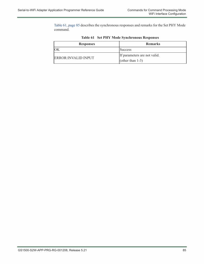
Serial-to-WiFi Adapter Application Programmer Reference Guide Commands for Command Processing ModeWiFi Interface Configuration
Table 61, page 85 describes the synchronous responses and remarks for the Set PHY Mode command.
Table 61 Set PHY Mode Synchronous Responses
Responses RemarksOK Success
ERROR:INVALID INPUTIf parameters are not valid.(other than 1-3)
GS1500-S2W-APP-PRG-RG-001208, Release 5.21 85
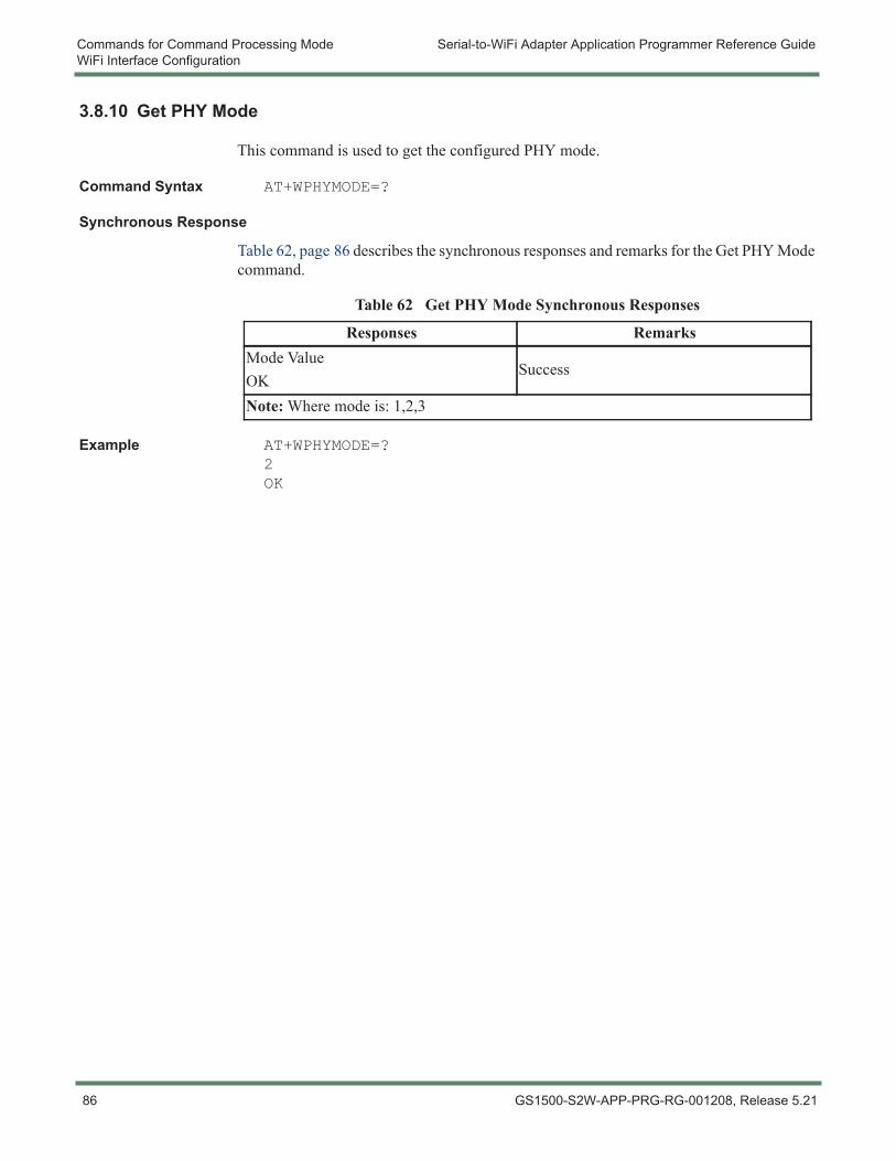
Commands for Command Processing Mode Serial-to-WiFi Adapter Application Programmer Reference GuideWiFi Interface Configuration
3.8.10 Get PHY Mode
This command is used to get the configured PHY mode.
Command Syntax AT+WPHYMODE=?
Synchronous Response
Table 62, page 86 describes the synchronous responses and remarks for the Get PHY Mode command.
Example AT+WPHYMODE=?2OK
Table 62 Get PHY Mode Synchronous Responses
Responses RemarksMode ValueOK
Success
Note: Where mode is: 1,2,3
86 GS1500-S2W-APP-PRG-RG-001208, Release 5.21
Serial-to-WiFi Adapter Application Programmer Reference Guide Commands for Command Processing ModeWiFi Interface Configuration
3.8.11 Associate with a Network, or Start an Ad Hoc or Infrastructure (AP) NetworkThis command is used to join an infrastructure network, create an infrastructure network (limited access point mode), and to create/join to an ad-hoc network.
Command Syntax AT+WA=<SSID>[,[<BSSID>][,<Ch>],{Rssi Flag]]
Usage The following are the behavior of the command in different modes:
1. In infrastructure mode, i.e., AT+WM=0 (see 3.8.8 Mode, page 83). The node will attempt to associate with the requested network. If the requested network is not available, an error message will display.
2. In ad-hoc mode, i.e., AT+WM=1 (see 3.8.8 Mode, page 83). The node will attempt to associate with the requested network. If the network with the desired SSID or channel or both is not found, then a new ad-hoc network is created. However, if BSSID is specified in the request, and the applicable BSSID is not found, the node will report an error and will not create a network.
3. In AP mode, i.e., AT+WM=2 (see 3.8.8 Mode, page 83), The node creates an infrastructure (Limited AP) network with the specified SSID. Issue AT+WSEC=n (refer 3.9.2 Security Configuration, page 102 for values) to create Limited AP with security as specified in Table 84Security Configuration Parameters, page 102.
GS1500-S2W-APP-PRG-RG-001208, Release 5.21 87
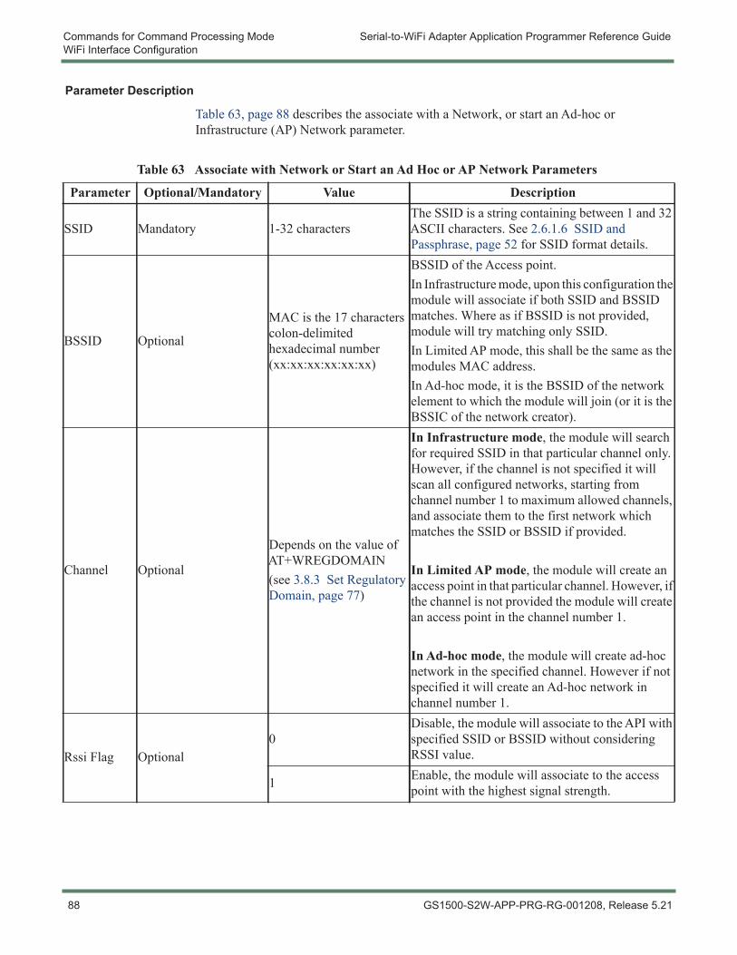
Commands for Command Processing Mode Serial-to-WiFi Adapter Application Programmer Reference GuideWiFi Interface Configuration
Parameter Description
Table 63, page 88 describes the associate with a Network, or start an Ad-hoc or Infrastructure (AP) Network parameter.
Table 63 Associate with Network or Start an Ad Hoc or AP Network Parameters
Parameter Optional/Mandatory Value Description
SSID Mandatory 1-32 charactersThe SSID is a string containing between 1 and 32 ASCII characters. See 2.6.1.6 SSID and Passphrase, page 52 for SSID format details.
BSSID Optional
MAC is the 17 characters colon-delimited hexadecimal number (xx:xx:xx:xx:xx:xx)
BSSID of the Access point.In Infrastructure mode, upon this configuration the module will associate if both SSID and BSSID matches. Where as if BSSID is not provided, module will try matching only SSID.In Limited AP mode, this shall be the same as the modules MAC address.In Ad-hoc mode, it is the BSSID of the network element to which the module will join (or it is the BSSIC of the network creator).
Channel Optional
Depends on the value of AT+WREGDOMAIN (see 3.8.3 Set Regulatory Domain, page 77)
In Infrastructure mode, the module will search for required SSID in that particular channel only. However, if the channel is not specified it will scan all configured networks, starting from channel number 1 to maximum allowed channels, and associate them to the first network which matches the SSID or BSSID if provided.
In Limited AP mode, the module will create an access point in that particular channel. However, if the channel is not provided the module will create an access point in the channel number 1.
In Ad-hoc mode, the module will create ad-hoc network in the specified channel. However if not specified it will create an Ad-hoc network in channel number 1.
Rssi Flag Optional0
Disable, the module will associate to the API with specified SSID or BSSID without considering RSSI value.
1 Enable, the module will associate to the access point with the highest signal strength.
88 GS1500-S2W-APP-PRG-RG-001208, Release 5.21
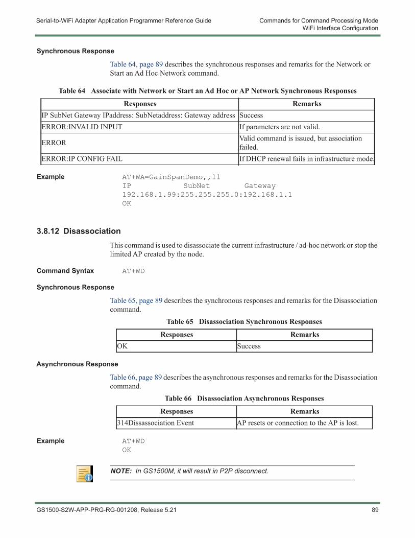
Serial-to-WiFi Adapter Application Programmer Reference Guide Commands for Command Processing ModeWiFi Interface Configuration
Synchronous Response
Table 64, page 89 describes the synchronous responses and remarks for the Network or Start an Ad Hoc Network command.
Example AT+WA=GainSpanDemo,,11IP SubNet Gateway192.168.1.99:255.255.255.0:192.168.1.1OK
3.8.12 DisassociationThis command is used to disassociate the current infrastructure / ad-hoc network or stop the limited AP created by the node.
Command Syntax AT+WD
Synchronous Response
Table 65, page 89 describes the synchronous responses and remarks for the Disassociation command.
Asynchronous Response
Table 66, page 89 describes the asynchronous responses and remarks for the Disassociation command.
Example AT+WDOK
Table 64 Associate with Network or Start an Ad Hoc or AP Network Synchronous Responses
Responses RemarksIP SubNet Gateway IPaddress: SubNetaddress: Gateway address SuccessERROR:INVALID INPUT If parameters are not valid.
ERROR Valid command is issued, but association failed.
ERROR:IP CONFIG FAIL If DHCP renewal fails in infrastructure mode.
Table 65 Disassociation Synchronous Responses
Responses RemarksOK Success
Table 66 Disassociation Asynchronous Responses
Responses Remarks314Dissassociation Event AP resets or connection to the AP is lost.
NOTE: In GS1500M, it will result in P2P disconnect.
GS1500-S2W-APP-PRG-RG-001208, Release 5.21 89
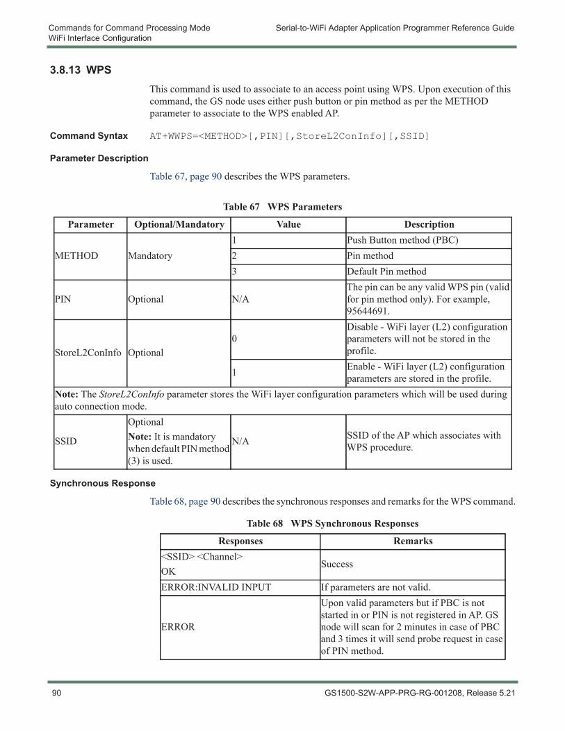
Commands for Command Processing Mode Serial-to-WiFi Adapter Application Programmer Reference GuideWiFi Interface Configuration
3.8.13 WPSThis command is used to associate to an access point using WPS. Upon execution of this command, the GS node uses either push button or pin method as per the METHOD parameter to associate to the WPS enabled AP.
Command Syntax AT+WWPS=<METHOD>[,PIN][,StoreL2ConInfo][,SSID]
Parameter Description
Table 67, page 90 describes the WPS parameters.
Synchronous Response
Table 68, page 90 describes the synchronous responses and remarks for the WPS command.
Table 67 WPS Parameters
Parameter Optional/Mandatory Value Description
METHOD Mandatory1 Push Button method (PBC)2 Pin method3 Default Pin method
PIN Optional N/AThe pin can be any valid WPS pin (valid for pin method only). For example, 95644691.
StoreL2ConInfo Optional0
Disable - WiFi layer (L2) configuration parameters will not be stored in the profile.
1 Enable - WiFi layer (L2) configuration parameters are stored in the profile.
Note: The StoreL2ConInfo parameter stores the WiFi layer configuration parameters which will be used during auto connection mode.
SSID
OptionalNote: It is mandatory when default PIN method (3) is used.
N/A SSID of the AP which associates with WPS procedure.
Table 68 WPS Synchronous Responses
Responses Remarks<SSID> <Channel>OK
Success
ERROR:INVALID INPUT If parameters are not valid.
ERROR
Upon valid parameters but if PBC is not started in or PIN is not registered in AP. GS node will scan for 2 minutes in case of PBC and 3 times it will send probe request in case of PIN method.
90 GS1500-S2W-APP-PRG-RG-001208, Release 5.21
Serial-to-WiFi Adapter Application Programmer Reference Guide Commands for Command Processing ModeWiFi Interface Configuration
Command Note Upon success, host shall issue AT+NDHCP=1 to acquire network address (IP address) or configure the IP address statically (AT+NSET).
Example 1 - Push Button Configuration (PBC) method
AT+WWPS=1,,1SSID=GainSpanDemoCHANNEL=11OK
Example 2 - PIN method
AT+WWPS=2,40057583,,1SSID=GainSpanDemoCHANNEL=11OK
GS1500-S2W-APP-PRG-RG-001208, Release 5.21 91
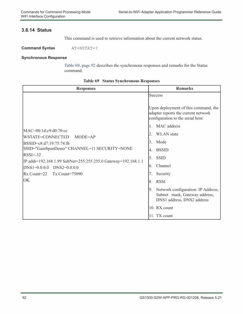
Commands for Command Processing Mode Serial-to-WiFi Adapter Application Programmer Reference GuideWiFi Interface Configuration
3.8.14 StatusThis command is used to retrieve information about the current network status.
Command Syntax AT+NSTAT=?
Synchronous Response
Table 69, page 92 describes the synchronous responses and remarks for the Status command.
Table 69 Status Synchronous Responses
Responses Remarks
MAC=00:1d:c9:d0:70:ccWSTATE=CONNECTED MODE=APBSSID=c8:d7:19:75:74:fbSSID="GainSpanDemo" CHANNEL=11 SECURITY=NONERSSI=-32IP addr=192.168.1.99 SubNet=255.255.255.0 Gateway=192.168.1.1DNS1=0.0.0.0 DNS2=0.0.0.0Rx Count=22 Tx Count=75090OK
Success
Upon deployment of this command, the adapter reports the current network configuration to the serial host:
1. MAC address
2. WLAN state
3. Mode
4. BSSID
5. SSID
6. Channel
7. Security
8. RSSI
9. Network configuration: IP Address, Subnet mask, Gateway address, DNS1 address, DNS2 address
10. RX count
11. TX count
92 GS1500-S2W-APP-PRG-RG-001208, Release 5.21
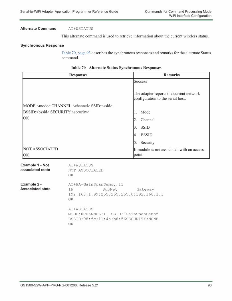
Serial-to-WiFi Adapter Application Programmer Reference Guide Commands for Command Processing ModeWiFi Interface Configuration
Alternate Command AT+WSTATUS
This alternate command is used to retrieve information about the current wireless status.
Synchronous Response
Table 70, page 93 describes the synchronous responses and remarks for the alternate Status command.
Example 1 - Not associated state
AT+WSTATUSNOT ASSOCIATEDOK
Example 2 - Associated state
AT+WA=GainSpanDemo,,11IP SubNet Gateway192.168.1.99:255.255.255.0:192.168.1.1OK
AT+WSTATUSMODE:0CHANNEL:11 SSID:”GainSpanDemo”BSSID:98:fc:11:4a:b8:56SECURITY:NONEOK
Table 70 Alternate Status Synchronous Responses
Responses Remarks
MODE:<mode> CHANNEL:<channel> SSID:<ssid>BSSID:<bssid> SECURITY:<security>OK
Success
The adapter reports the current network configuration to the serial host:
1. Mode
2. Channel
3. SSID
4. BSSID
5. SecurityNOT ASSOCIATEDOK
If module is not associated with an access point.
GS1500-S2W-APP-PRG-RG-001208, Release 5.21 93
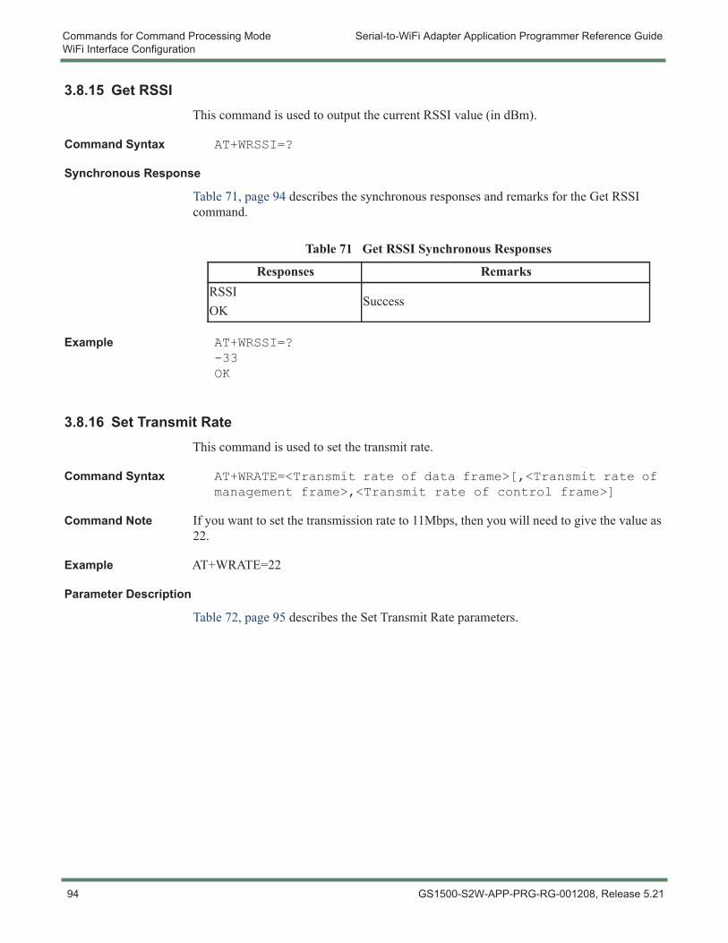
Commands for Command Processing Mode Serial-to-WiFi Adapter Application Programmer Reference GuideWiFi Interface Configuration
3.8.15 Get RSSIThis command is used to output the current RSSI value (in dBm).
Command Syntax AT+WRSSI=?
Synchronous Response
Table 71, page 94 describes the synchronous responses and remarks for the Get RSSI command.
Example AT+WRSSI=?-33OK
3.8.16 Set Transmit RateThis command is used to set the transmit rate.
Command Syntax AT+WRATE=<Transmit rate of data frame>[,<Transmit rate of management frame>,<Transmit rate of control frame>]
Command Note If you want to set the transmission rate to 11Mbps, then you will need to give the value as 22.
Example AT+WRATE=22
Parameter Description
Table 72, page 95 describes the Set Transmit Rate parameters.
Table 71 Get RSSI Synchronous Responses
Responses RemarksRSSIOK
Success
94 GS1500-S2W-APP-PRG-RG-001208, Release 5.21
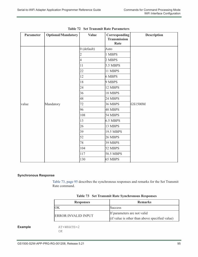
Serial-to-WiFi Adapter Application Programmer Reference Guide Commands for Command Processing ModeWiFi Interface Configuration
Synchronous Response
Table 73, page 95 describes the synchronous responses and remarks for the Set Transmit Rate command.
Example AT+WRATE=2OK
Table 72 Set Transmit Rate Parameters
Parameter Optional/Mandatory Value Corresponding Transmission
Rate
Description
value Mandatory
0 (default) Auto
GS1500M
2 1 MBPS4 2 MBPS11 5.5 MBPS22 11 MBPS12 6 MBPS18 9 MBPS24 12 MBPS36 18 MBPS48 24 MBPS72 36 MBPS96 48 MBPS108 54 MBPS13 6.5 MBPS26 13 MBPS39 19.5 MBPS52 26 MBPS78 39 MBPS104 52 MBPS117 58.5 MBPS130 65 MBPS
Table 73 Set Transmit Rate Synchronous Responses
Responses RemarksOK Success
ERROR:INVALID INPUTIf parameters are not valid(if value is other than above specified value)
GS1500-S2W-APP-PRG-RG-001208, Release 5.21 95
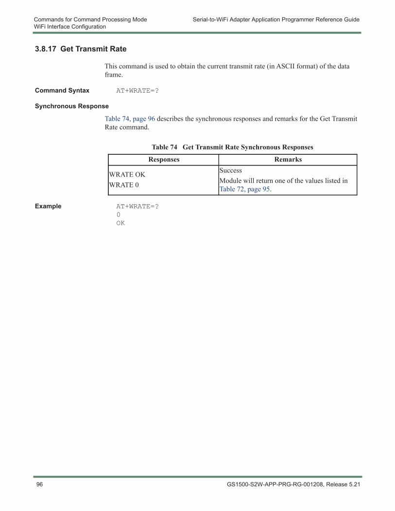
Commands for Command Processing Mode Serial-to-WiFi Adapter Application Programmer Reference GuideWiFi Interface Configuration
3.8.17 Get Transmit Rate
This command is used to obtain the current transmit rate (in ASCII format) of the data frame.
Command Syntax AT+WRATE=?
Synchronous Response
Table 74, page 96 describes the synchronous responses and remarks for the Get Transmit Rate command.
Example AT+WRATE=?0OK
Table 74 Get Transmit Rate Synchronous Responses
Responses Remarks
WRATE OKWRATE 0
SuccessModule will return one of the values listed in Table 72, page 95.
96 GS1500-S2W-APP-PRG-RG-001208, Release 5.21
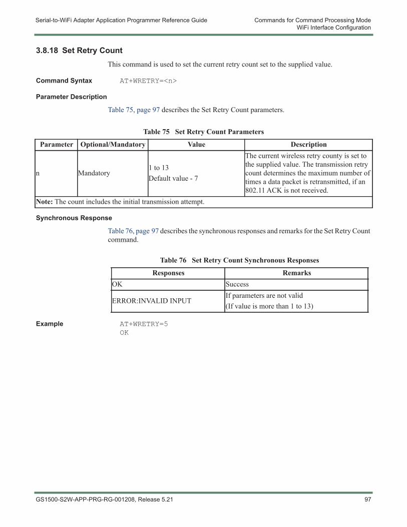
Serial-to-WiFi Adapter Application Programmer Reference Guide Commands for Command Processing ModeWiFi Interface Configuration
3.8.18 Set Retry CountThis command is used to set the current retry count set to the supplied value.
Command Syntax AT+WRETRY=<n>
Parameter Description
Table 75, page 97 describes the Set Retry Count parameters.
Synchronous Response
Table 76, page 97 describes the synchronous responses and remarks for the Set Retry Count command.
Example AT+WRETRY=5OK
Table 75 Set Retry Count Parameters
Parameter Optional/Mandatory Value Description
n Mandatory1 to 13Default value - 7
The current wireless retry county is set to the supplied value. The transmission retry count determines the maximum number of times a data packet is retransmitted, if an 802.11 ACK is not received.
Note: The count includes the initial transmission attempt.
Table 76 Set Retry Count Synchronous Responses
Responses RemarksOK Success
ERROR:INVALID INPUTIf parameters are not valid(If value is more than 1 to 13)
GS1500-S2W-APP-PRG-RG-001208, Release 5.21 97
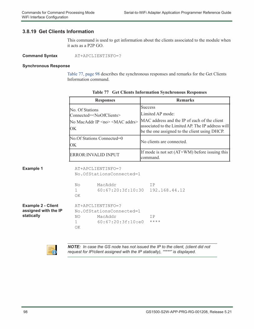
Commands for Command Processing Mode Serial-to-WiFi Adapter Application Programmer Reference GuideWiFi Interface Configuration
3.8.19 Get Clients InformationThis command is used to get information about the clients associated to the module when it acts as a P2P GO.
Command Syntax AT+APCLIENTINFO=?
Synchronous Response
Table 77, page 98 describes the synchronous responses and remarks for the Get Clients Information command.
Example 1 AT+APCLIENTINFO=?No.OfStationsConnected=1
No MacAddr IP1 60:67:20:3f:10:30 192.168.44.12OK
Example 2 - Client assigned with the IP statically
AT+APCLIENTINFO=?No.OfStationsConnected=1NO MacAddr IP1 60:67:20:3f:10:e0 ****OK
Table 77 Get Clients Information Synchronous Responses
Responses Remarks
No. Of Stations Connected=<NoOfClients>No MacAddr IP <no> <MAC addrs>OK
SuccessLimited AP mode:MAC address and the IP of each of the client associated to the Limited AP. The IP address will be the one assigned to the client using DHCP.
No.Of Stations Connected=0OK
No clients are connected.
ERROR:INVALID INPUT If mode is not set (AT+WM) before issuing this command.
NOTE: In case the GS node has not issued the IP to the client, (client did not request for IP/client assigned with the IP statically), “****” is displayed.
98 GS1500-S2W-APP-PRG-RG-001208, Release 5.21
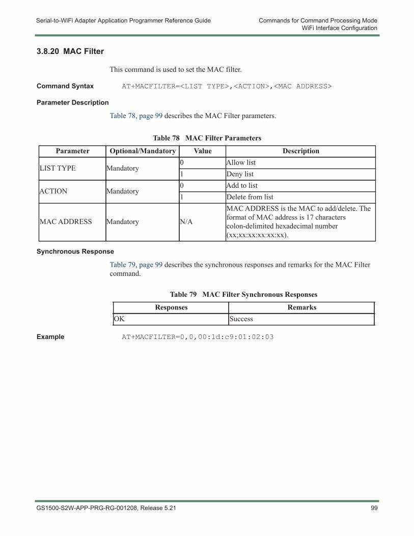
Serial-to-WiFi Adapter Application Programmer Reference Guide Commands for Command Processing ModeWiFi Interface Configuration
3.8.20 MAC Filter
This command is used to set the MAC filter.
Command Syntax AT+MACFILTER=<LIST TYPE>,<ACTION>,<MAC ADDRESS>
Parameter Description
Table 78, page 99 describes the MAC Filter parameters.
Synchronous Response
Table 79, page 99 describes the synchronous responses and remarks for the MAC Filter command.
Example AT+MACFILTER=0,0,00:1d:c9:01:02:03
Table 78 MAC Filter Parameters
Parameter Optional/Mandatory Value Description
LIST TYPE Mandatory0 Allow list1 Deny list
ACTION Mandatory0 Add to list1 Delete from list
MAC ADDRESS Mandatory N/A
MAC ADDRESS is the MAC to add/delete. The format of MAC address is 17 characters colon-delimited hexadecimal number (xx;xx:xx:xx:xx:xx).
Table 79 MAC Filter Synchronous Responses
Responses RemarksOK Success
GS1500-S2W-APP-PRG-RG-001208, Release 5.21 99
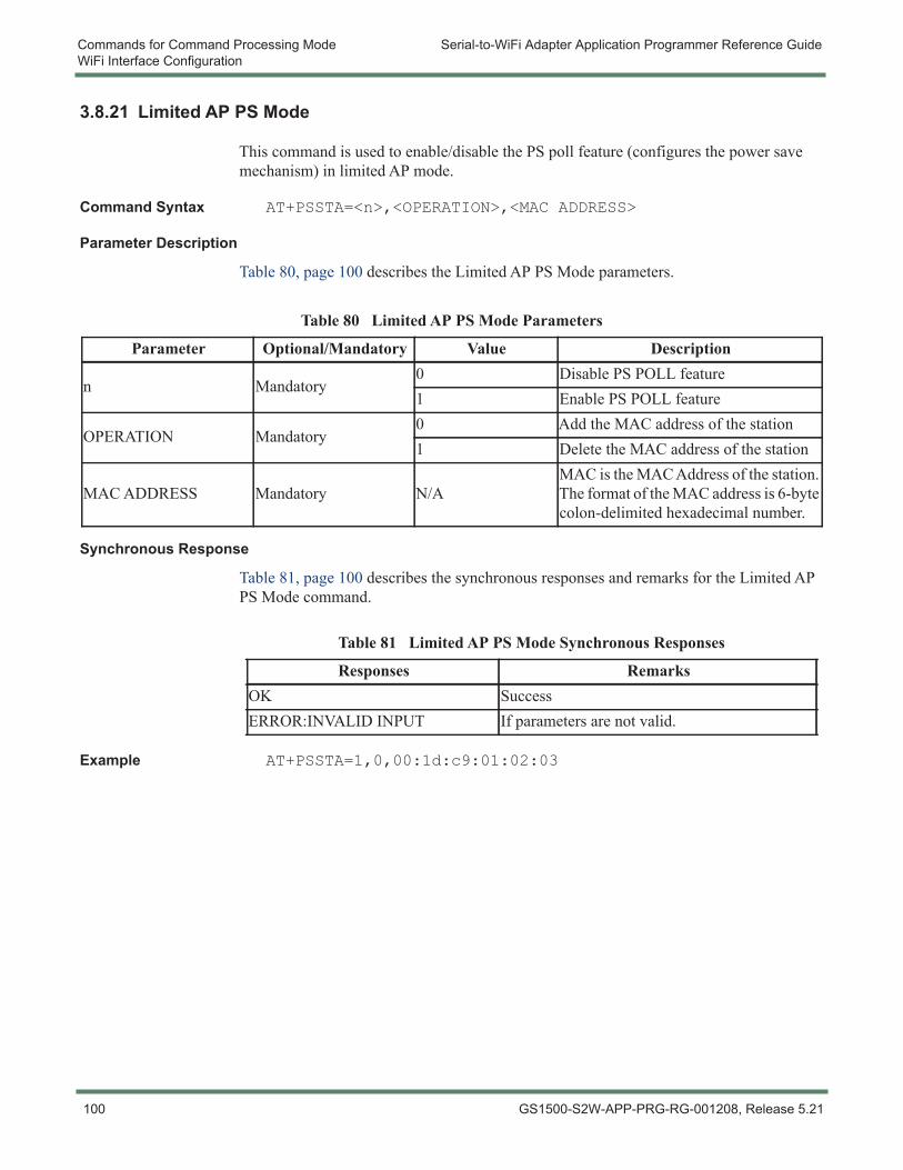
Commands for Command Processing Mode Serial-to-WiFi Adapter Application Programmer Reference GuideWiFi Interface Configuration
3.8.21 Limited AP PS Mode
This command is used to enable/disable the PS poll feature (configures the power save mechanism) in limited AP mode.
Command Syntax AT+PSSTA=<n>,<OPERATION>,<MAC ADDRESS>
Parameter Description
Table 80, page 100 describes the Limited AP PS Mode parameters.
Synchronous Response
Table 81, page 100 describes the synchronous responses and remarks for the Limited AP PS Mode command.
Example AT+PSSTA=1,0,00:1d:c9:01:02:03
Table 80 Limited AP PS Mode Parameters
Parameter Optional/Mandatory Value Description
n Mandatory0 Disable PS POLL feature1 Enable PS POLL feature
OPERATION Mandatory0 Add the MAC address of the station1 Delete the MAC address of the station
MAC ADDRESS Mandatory N/AMAC is the MAC Address of the station. The format of the MAC address is 6-byte colon-delimited hexadecimal number.
Table 81 Limited AP PS Mode Synchronous Responses
Responses RemarksOK SuccessERROR:INVALID INPUT If parameters are not valid.
100 GS1500-S2W-APP-PRG-RG-001208, Release 5.21
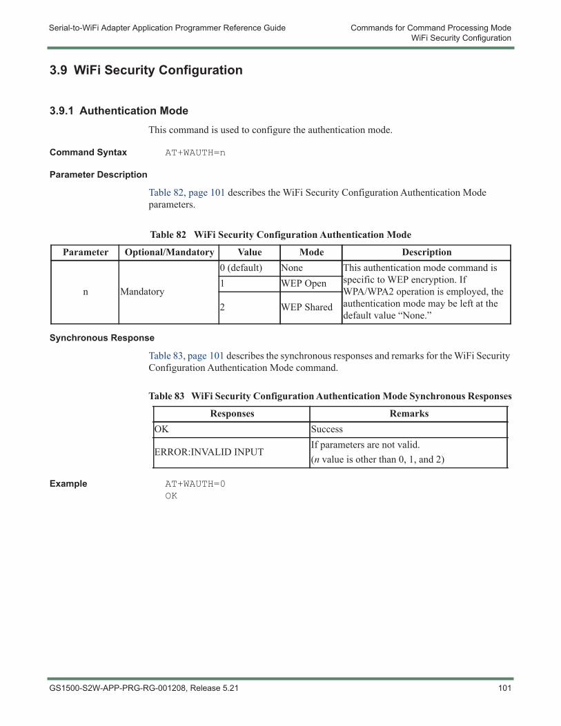
Serial-to-WiFi Adapter Application Programmer Reference Guide Commands for Command Processing ModeWiFi Security Configuration
3.9 WiFi Security Configuration
3.9.1 Authentication ModeThis command is used to configure the authentication mode.
Command Syntax AT+WAUTH=n
Parameter Description
Table 82, page 101 describes the WiFi Security Configuration Authentication Mode parameters.
Synchronous Response
Table 83, page 101 describes the synchronous responses and remarks for the WiFi Security Configuration Authentication Mode command.
Example AT+WAUTH=0OK
Table 82 WiFi Security Configuration Authentication Mode
Parameter Optional/Mandatory Value Mode Description
n Mandatory
0 (default) None This authentication mode command is specific to WEP encryption. If WPA/WPA2 operation is employed, the authentication mode may be left at the default value “None.”
1 WEP Open
2 WEP Shared
Table 83 WiFi Security Configuration Authentication Mode Synchronous Responses
Responses RemarksOK Success
ERROR:INVALID INPUTIf parameters are not valid.(n value is other than 0, 1, and 2)
GS1500-S2W-APP-PRG-RG-001208, Release 5.21 101
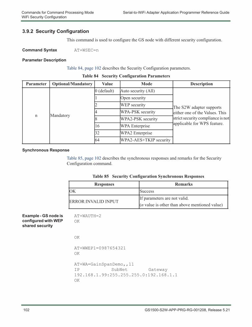
Commands for Command Processing Mode Serial-to-WiFi Adapter Application Programmer Reference GuideWiFi Security Configuration
3.9.2 Security ConfigurationThis command is used to configure the GS node with different security configuration.
Command Syntax AT+WSEC=n
Parameter Description
Table 84, page 102 describes the Security Configuration parameters.
Synchronous Response
Table 85, page 102 describes the synchronous responses and remarks for the Security Configuration command.
Example - GS node is configured with WEP shared security
AT+WAUTH=2OK
OK
AT+WWEP1=0987654321OK
AT+WA=GainSpanDemo,,11IP SubNet Gateway192.168.1.99:255.255.255.0:192.168.1.1OK
Table 84 Security Configuration Parameters
Parameter Optional/Mandatory Value Mode Description
n Mandatory
0 (default) Auto security (All)
The S2W adapter supports either one of the Values. This strict security compliance is not applicable for WPS feature.
1 Open security2 WEP security4 WPA-PSK security8 WPA2-PSK security16 WPA Enterprise32 WPA2 Enterprise64 WPA2-AES+TKIP security
Table 85 Security Configuration Synchronous Responses
Responses RemarksOK Success
ERROR:INVALID INPUTIf parameters are not valid.(n value is other than above mentioned value)
102 GS1500-S2W-APP-PRG-RG-001208, Release 5.21
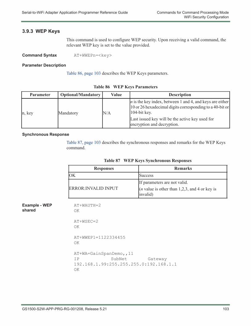
Serial-to-WiFi Adapter Application Programmer Reference Guide Commands for Command Processing ModeWiFi Security Configuration
3.9.3 WEP KeysThis command is used to configure WEP security. Upon receiving a valid command, the relevant WEP key is set to the value provided.
Command Syntax AT+WWEPn=<key>
Parameter Description
Table 86, page 103 describes the WEP Keys parameters.
Synchronous Response
Table 87, page 103 describes the synchronous responses and remarks for the WEP Keys command.
Example - WEP shared
AT+WAUTH=2OK
AT+WSEC=2OK
AT+WWEP1=1122334455OK
AT+WA=GainSpanDemo,,11IP SubNet Gateway192.168.1.99:255.255.255.0:192.168.1.1OK
Table 86 WEP Keys Parameters
Parameter Optional/Mandatory Value Description
n, key Mandatory N/A
n is the key index, between 1 and 4, and keys are either 10 or 26 hexadecimal digits corresponding to a 40-bit or 104-bit key.Last issued key will be the active key used for encryption and decryption.
Table 87 WEP Keys Synchronous Responses
Responses RemarksOK Success
ERROR:INVALID INPUTIf parameters are not valid.(n value is other than 1,2,3, and 4 or key is invalid)
GS1500-S2W-APP-PRG-RG-001208, Release 5.21 103
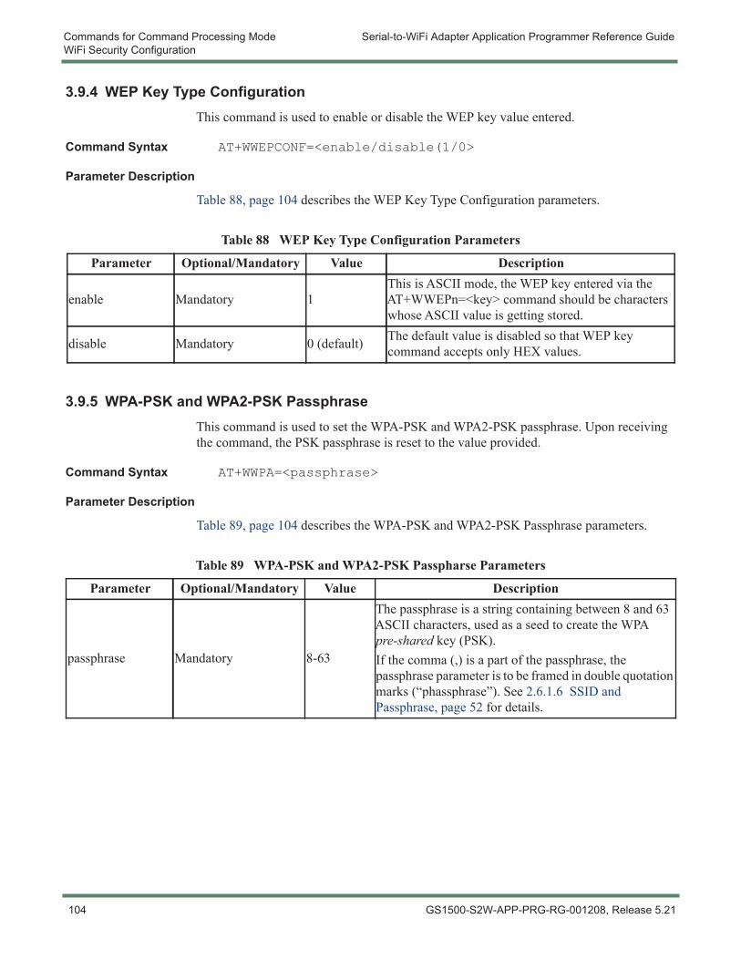
Commands for Command Processing Mode Serial-to-WiFi Adapter Application Programmer Reference GuideWiFi Security Configuration
3.9.4 WEP Key Type ConfigurationThis command is used to enable or disable the WEP key value entered.
Command Syntax AT+WWEPCONF=<enable/disable(1/0>
Parameter Description
Table 88, page 104 describes the WEP Key Type Configuration parameters.
3.9.5 WPA-PSK and WPA2-PSK PassphraseThis command is used to set the WPA-PSK and WPA2-PSK passphrase. Upon receiving the command, the PSK passphrase is reset to the value provided.
Command Syntax AT+WWPA=<passphrase>
Parameter Description
Table 89, page 104 describes the WPA-PSK and WPA2-PSK Passphrase parameters.
Table 88 WEP Key Type Configuration Parameters
Parameter Optional/Mandatory Value Description
enable Mandatory 1This is ASCII mode, the WEP key entered via the AT+WWEPn=<key> command should be characters whose ASCII value is getting stored.
disable Mandatory 0 (default) The default value is disabled so that WEP key command accepts only HEX values.
Table 89 WPA-PSK and WPA2-PSK Passpharse Parameters
Parameter Optional/Mandatory Value Description
passphrase Mandatory 8-63
The passphrase is a string containing between 8 and 63 ASCII characters, used as a seed to create the WPA pre-shared key (PSK).If the comma (,) is a part of the passphrase, the passphrase parameter is to be framed in double quotation marks (“phassphrase”). See 2.6.1.6 SSID and Passphrase, page 52 for details.
104 GS1500-S2W-APP-PRG-RG-001208, Release 5.21
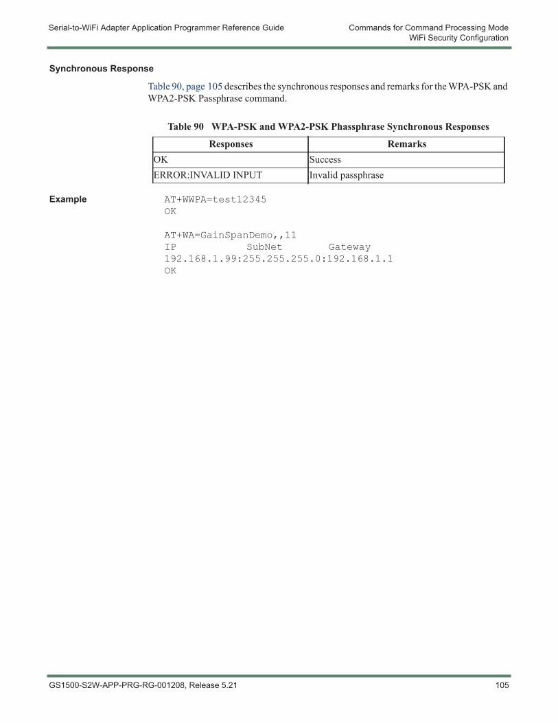
Serial-to-WiFi Adapter Application Programmer Reference Guide Commands for Command Processing ModeWiFi Security Configuration
Synchronous Response
Table 90, page 105 describes the synchronous responses and remarks for the WPA-PSK and WPA2-PSK Passphrase command.
Example AT+WWPA=test12345OK
AT+WA=GainSpanDemo,,11IP SubNet Gateway192.168.1.99:255.255.255.0:192.168.1.1OK
Table 90 WPA-PSK and WPA2-PSK Phassphrase Synchronous Responses
Responses RemarksOK SuccessERROR:INVALID INPUT Invalid passphrase
GS1500-S2W-APP-PRG-RG-001208, Release 5.21 105
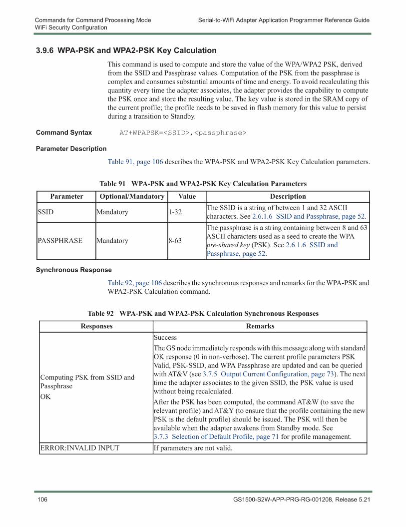
Commands for Command Processing Mode Serial-to-WiFi Adapter Application Programmer Reference GuideWiFi Security Configuration
3.9.6 WPA-PSK and WPA2-PSK Key CalculationThis command is used to compute and store the value of the WPA/WPA2 PSK, derived from the SSID and Passphrase values. Computation of the PSK from the passphrase is complex and consumes substantial amounts of time and energy. To avoid recalculating this quantity every time the adapter associates, the adapter provides the capability to compute the PSK once and store the resulting value. The key value is stored in the SRAM copy of the current profile; the profile needs to be saved in flash memory for this value to persist during a transition to Standby.
Command Syntax AT+WPAPSK=<SSID>,<passphrase>
Parameter Description
Table 91, page 106 describes the WPA-PSK and WPA2-PSK Key Calculation parameters.
Synchronous Response
Table 92, page 106 describes the synchronous responses and remarks for the WPA-PSK and WPA2-PSK Calculation command.
Table 91 WPA-PSK and WPA2-PSK Key Calculation Parameters
Parameter Optional/Mandatory Value Description
SSID Mandatory 1-32 The SSID is a string of between 1 and 32 ASCII characters. See 2.6.1.6 SSID and Passphrase, page 52.
PASSPHRASE Mandatory 8-63
The passphrase is a string containing between 8 and 63 ASCII characters used as a seed to create the WPA pre-shared key (PSK). See 2.6.1.6 SSID and Passphrase, page 52.
Table 92 WPA-PSK and WPA2-PSK Calculation Synchronous Responses
Responses Remarks
Computing PSK from SSID and PassphraseOK
SuccessThe GS node immediately responds with this message along with standard OK response (0 in non-verbose). The current profile parameters PSK Valid, PSK-SSID, and WPA Passphrase are updated and can be queried with AT&V (see 3.7.5 Output Current Configuration, page 73). The next time the adapter associates to the given SSID, the PSK value is used without being recalculated.After the PSK has been computed, the command AT&W (to save the relevant profile) and AT&Y (to ensure that the profile containing the new PSK is the default profile) should be issued. The PSK will then be available when the adapter awakens from Standby mode. See 3.7.3 Selection of Default Profile, page 71 for profile management.
ERROR:INVALID INPUT If parameters are not valid.
106 GS1500-S2W-APP-PRG-RG-001208, Release 5.21
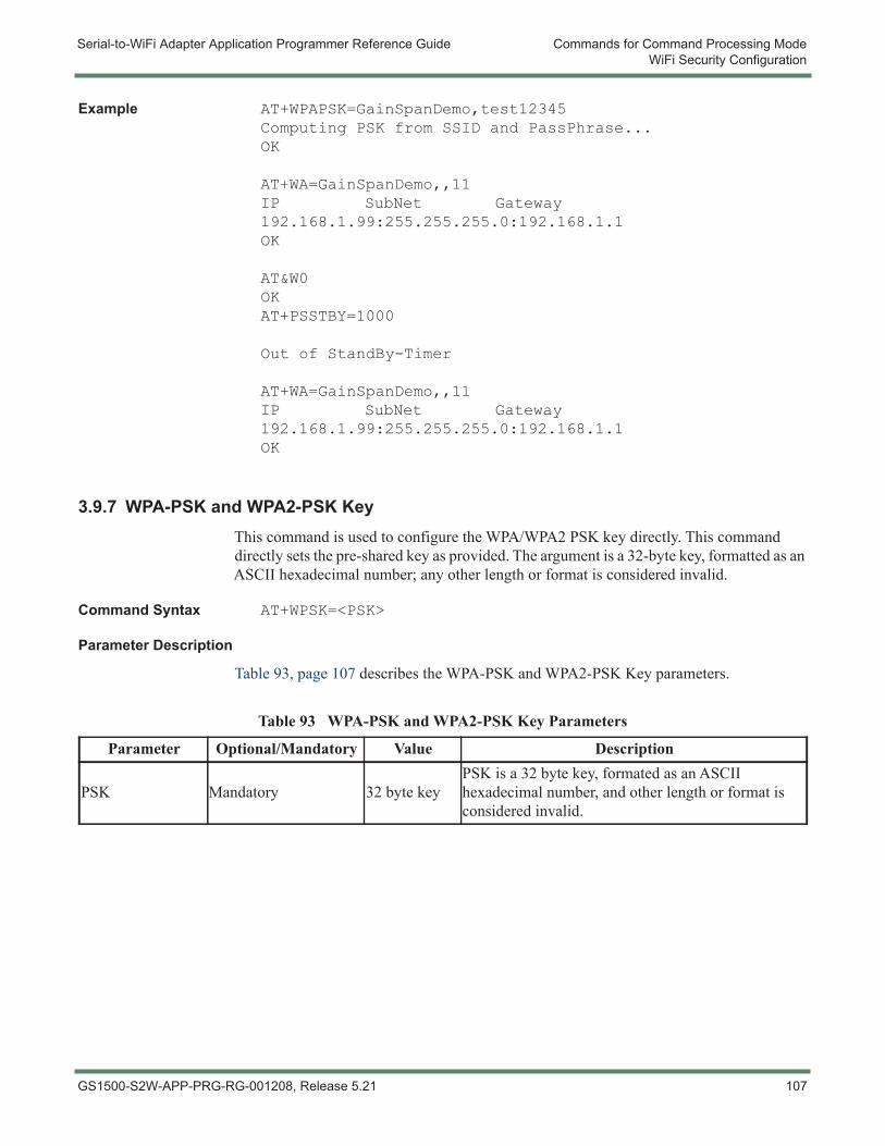
Serial-to-WiFi Adapter Application Programmer Reference Guide Commands for Command Processing ModeWiFi Security Configuration
Example AT+WPAPSK=GainSpanDemo,test12345Computing PSK from SSID and PassPhrase...OK
AT+WA=GainSpanDemo,,11IP SubNet Gateway192.168.1.99:255.255.255.0:192.168.1.1OK
AT&W0OKAT+PSSTBY=1000
Out of StandBy-Timer
AT+WA=GainSpanDemo,,11IP SubNet Gateway192.168.1.99:255.255.255.0:192.168.1.1OK
3.9.7 WPA-PSK and WPA2-PSK KeyThis command is used to configure the WPA/WPA2 PSK key directly. This command directly sets the pre-shared key as provided. The argument is a 32-byte key, formatted as an ASCII hexadecimal number; any other length or format is considered invalid.
Command Syntax AT+WPSK=<PSK>
Parameter Description
Table 93, page 107 describes the WPA-PSK and WPA2-PSK Key parameters.
Table 93 WPA-PSK and WPA2-PSK Key Parameters
Parameter Optional/Mandatory Value Description
PSK Mandatory 32 byte keyPSK is a 32 byte key, formated as an ASCII hexadecimal number, and other length or format is considered invalid.
GS1500-S2W-APP-PRG-RG-001208, Release 5.21 107
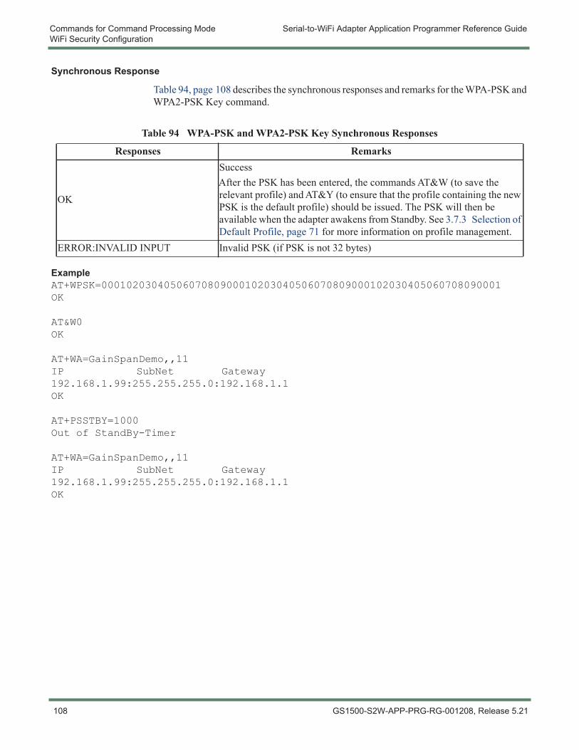
Commands for Command Processing Mode Serial-to-WiFi Adapter Application Programmer Reference GuideWiFi Security Configuration
Synchronous Response
Table 94, page 108 describes the synchronous responses and remarks for the WPA-PSK and WPA2-PSK Key command.
Example AT+WPSK=0001020304050607080900010203040506070809000102030405060708090001OK
AT&W0OK
AT+WA=GainSpanDemo,,11IP SubNet Gateway192.168.1.99:255.255.255.0:192.168.1.1OK
AT+PSSTBY=1000Out of StandBy-Timer
AT+WA=GainSpanDemo,,11IP SubNet Gateway192.168.1.99:255.255.255.0:192.168.1.1OK
Table 94 WPA-PSK and WPA2-PSK Key Synchronous Responses
Responses Remarks
OK
SuccessAfter the PSK has been entered, the commands AT&W (to save the relevant profile) and AT&Y (to ensure that the profile containing the new PSK is the default profile) should be issued. The PSK will then be available when the adapter awakens from Standby. See 3.7.3 Selection of Default Profile, page 71 for more information on profile management.
ERROR:INVALID INPUT Invalid PSK (if PSK is not 32 bytes)
108 GS1500-S2W-APP-PRG-RG-001208, Release 5.21
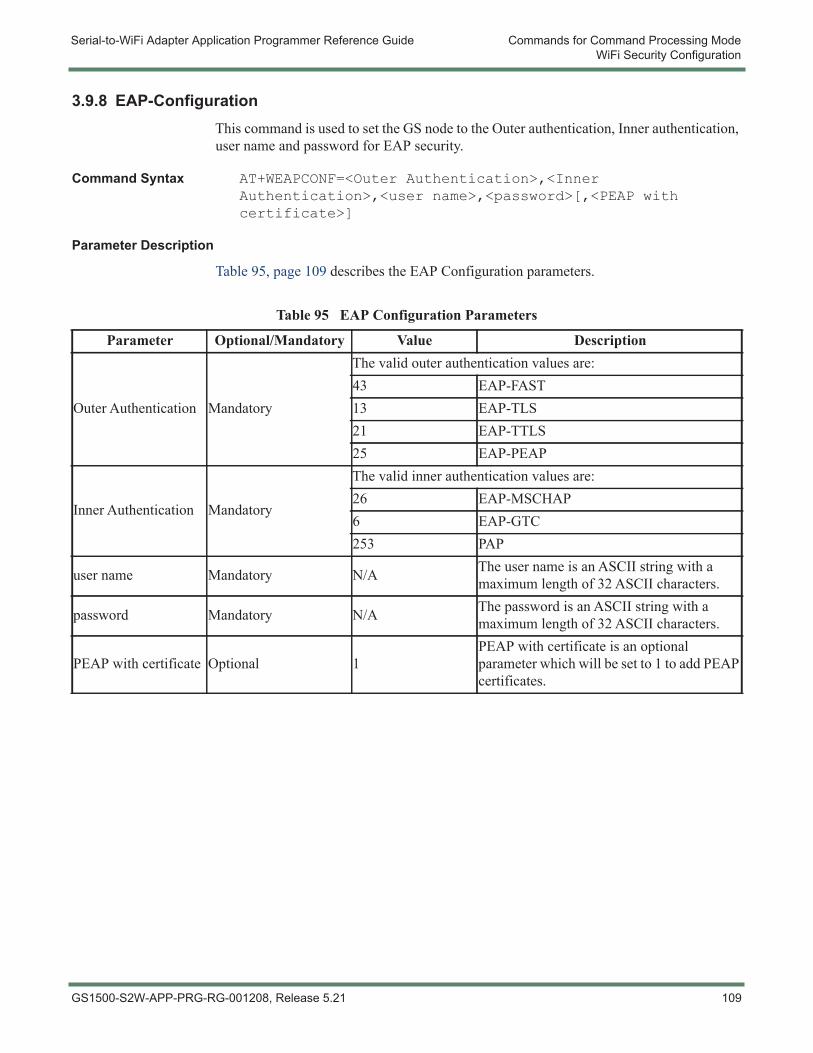
Serial-to-WiFi Adapter Application Programmer Reference Guide Commands for Command Processing ModeWiFi Security Configuration
3.9.8 EAP-ConfigurationThis command is used to set the GS node to the Outer authentication, Inner authentication, user name and password for EAP security.
Command Syntax AT+WEAPCONF=<Outer Authentication>,<Inner Authentication>,<user name>,<password>[,<PEAP with certificate>]
Parameter Description
Table 95, page 109 describes the EAP Configuration parameters.
Table 95 EAP Configuration Parameters
Parameter Optional/Mandatory Value Description
Outer Authentication Mandatory
The valid outer authentication values are:43 EAP-FAST13 EAP-TLS21 EAP-TTLS25 EAP-PEAP
Inner Authentication Mandatory
The valid inner authentication values are:26 EAP-MSCHAP6 EAP-GTC253 PAP
user name Mandatory N/A The user name is an ASCII string with a maximum length of 32 ASCII characters.
password Mandatory N/A The password is an ASCII string with a maximum length of 32 ASCII characters.
PEAP with certificate Optional 1PEAP with certificate is an optional parameter which will be set to 1 to add PEAP certificates.
GS1500-S2W-APP-PRG-RG-001208, Release 5.21 109
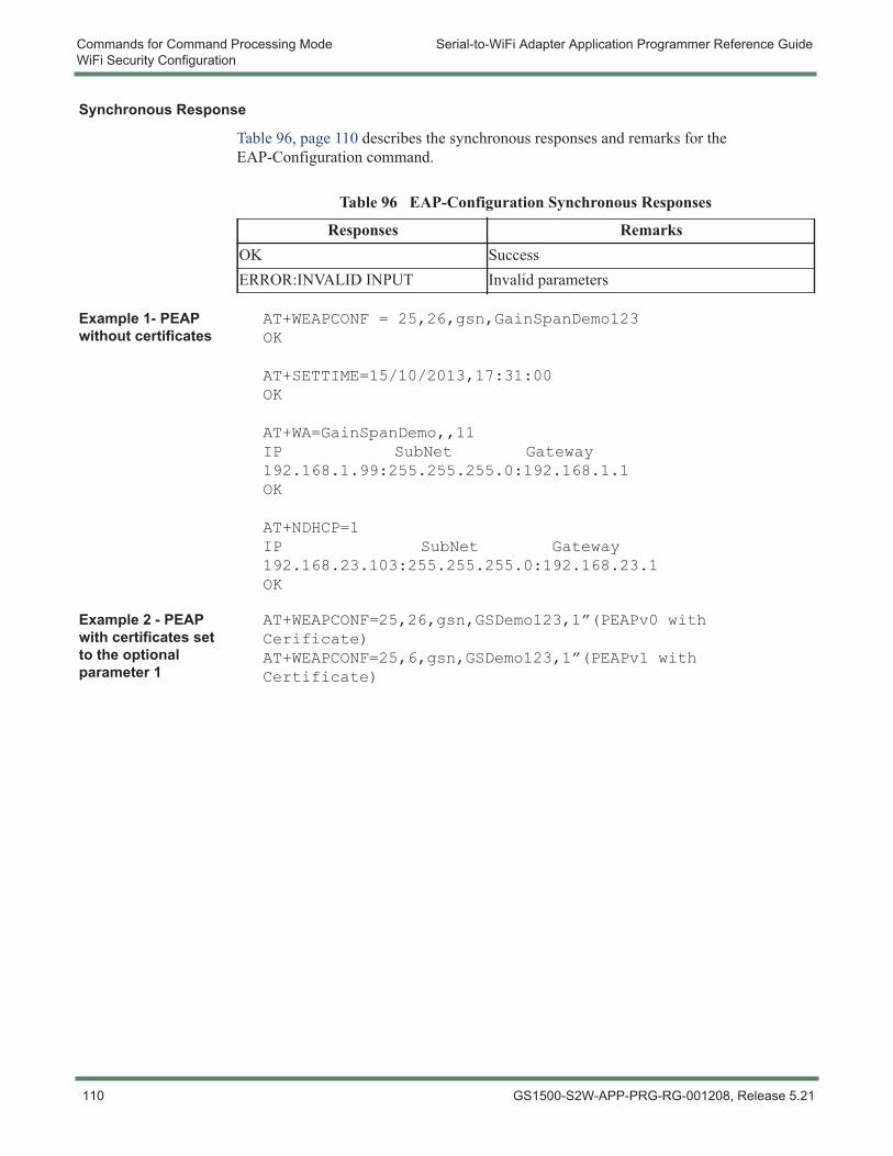
Commands for Command Processing Mode Serial-to-WiFi Adapter Application Programmer Reference GuideWiFi Security Configuration
Synchronous Response
Table 96, page 110 describes the synchronous responses and remarks for the EAP-Configuration command.
Example 1- PEAP without certificates
AT+WEAPCONF = 25,26,gsn,GainSpanDemo123OK
AT+SETTIME=15/10/2013,17:31:00OK
AT+WA=GainSpanDemo,,11IP SubNet Gateway192.168.1.99:255.255.255.0:192.168.1.1OK
AT+NDHCP=1IP SubNet Gateway192.168.23.103:255.255.255.0:192.168.23.1OK
Example 2 - PEAP with certificates set to the optional parameter 1
AT+WEAPCONF=25,26,gsn,GSDemo123,1”(PEAPv0 with Cerificate)AT+WEAPCONF=25,6,gsn,GSDemo123,1”(PEAPv1 with Certificate)
Table 96 EAP-Configuration Synchronous Responses
Responses RemarksOK SuccessERROR:INVALID INPUT Invalid parameters
110 GS1500-S2W-APP-PRG-RG-001208, Release 5.21
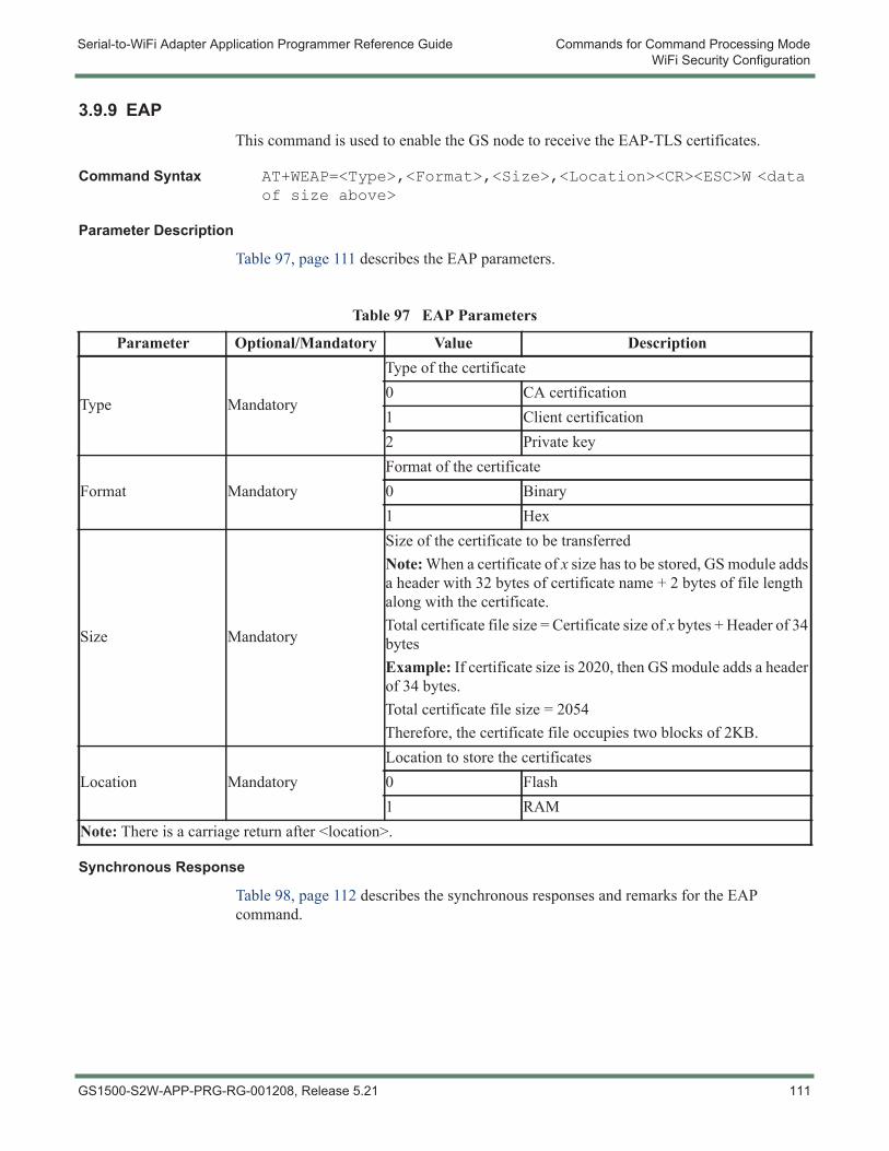
Serial-to-WiFi Adapter Application Programmer Reference Guide Commands for Command Processing ModeWiFi Security Configuration
3.9.9 EAPThis command is used to enable the GS node to receive the EAP-TLS certificates.
Command Syntax AT+WEAP=<Type>,<Format>,<Size>,<Location><CR><ESC>W <data of size above>
Parameter Description
Table 97, page 111 describes the EAP parameters.
Synchronous Response
Table 98, page 112 describes the synchronous responses and remarks for the EAP command.
Table 97 EAP Parameters
Parameter Optional/Mandatory Value Description
Type Mandatory
Type of the certificate0 CA certification1 Client certification2 Private key
Format MandatoryFormat of the certificate0 Binary 1 Hex
Size Mandatory
Size of the certificate to be transferredNote: When a certificate of x size has to be stored, GS module adds a header with 32 bytes of certificate name + 2 bytes of file length along with the certificate. Total certificate file size = Certificate size of x bytes + Header of 34 bytes Example: If certificate size is 2020, then GS module adds a header of 34 bytes.Total certificate file size = 2054Therefore, the certificate file occupies two blocks of 2KB.
Location MandatoryLocation to store the certificates0 Flash1 RAM
Note: There is a carriage return after <location>.
GS1500-S2W-APP-PRG-RG-001208, Release 5.21 111
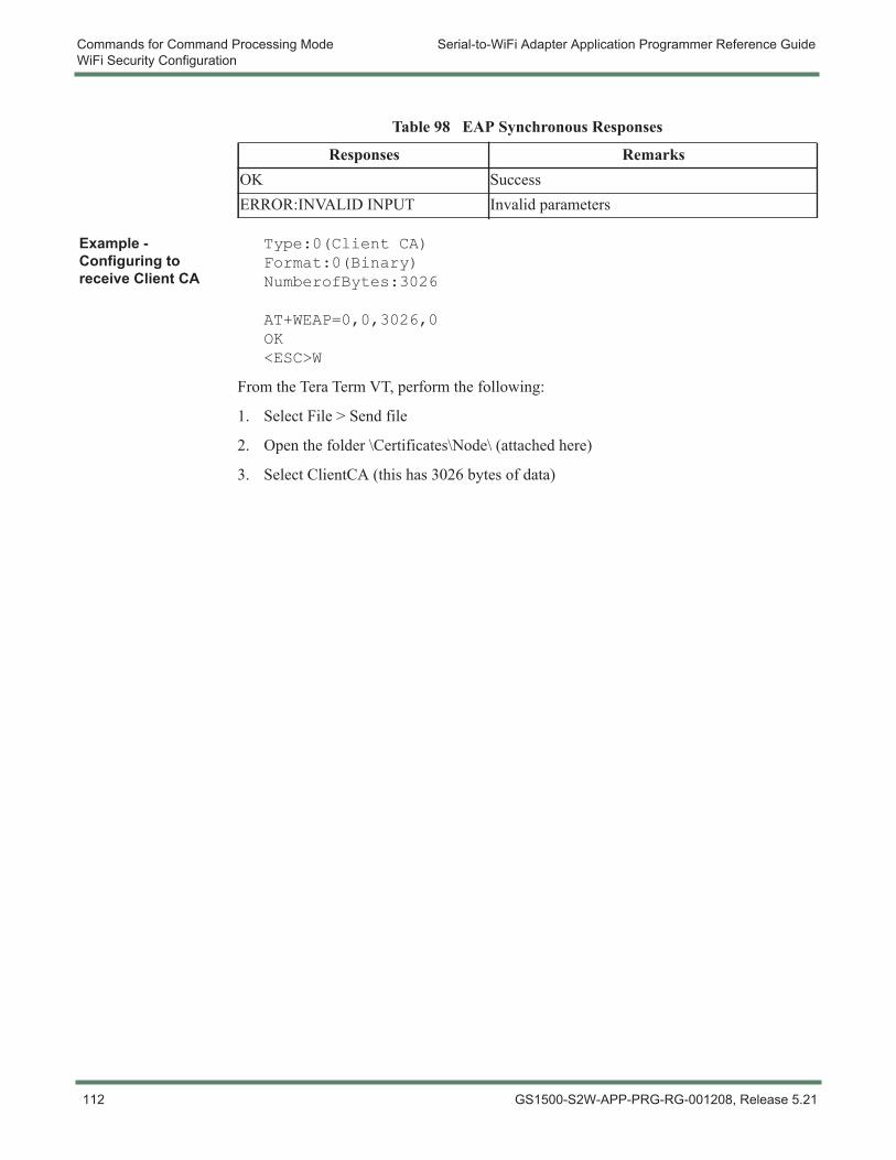
Commands for Command Processing Mode Serial-to-WiFi Adapter Application Programmer Reference GuideWiFi Security Configuration
Example - Configuring to receive Client CA
Type:0(Client CA)Format:0(Binary)NumberofBytes:3026
AT+WEAP=0,0,3026,0OK<ESC>W
From the Tera Term VT, perform the following:
1. Select File > Send file
2. Open the folder \Certificates\Node\ (attached here)
3. Select ClientCA (this has 3026 bytes of data)
Table 98 EAP Synchronous Responses
Responses RemarksOK SuccessERROR:INVALID INPUT Invalid parameters
112 GS1500-S2W-APP-PRG-RG-001208, Release 5.21
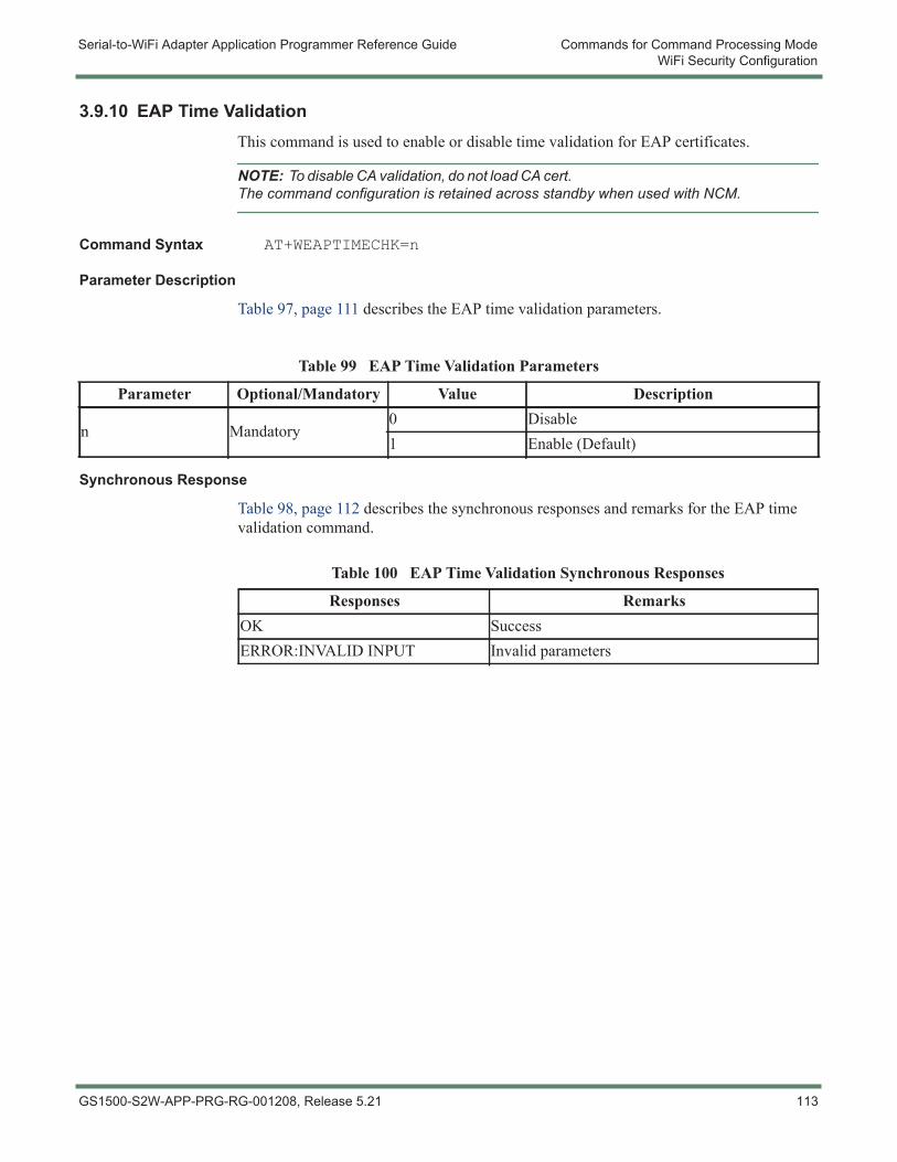
Serial-to-WiFi Adapter Application Programmer Reference Guide Commands for Command Processing ModeWiFi Security Configuration
3.9.10 EAP Time ValidationThis command is used to enable or disable time validation for EAP certificates.
NOTE: To disable CA validation, do not load CA cert. The command configuration is retained across standby when used with NCM.
Command Syntax AT+WEAPTIMECHK=n
Parameter Description
Table 97, page 111 describes the EAP time validation parameters.
Synchronous Response
Table 98, page 112 describes the synchronous responses and remarks for the EAP time validation command.
Table 99 EAP Time Validation Parameters
Parameter Optional/Mandatory Value Description
n Mandatory0 Disable1 Enable (Default)
Table 100 EAP Time Validation Synchronous Responses
Responses RemarksOK SuccessERROR:INVALID INPUT Invalid parameters
GS1500-S2W-APP-PRG-RG-001208, Release 5.21 113

Commands for Command Processing Mode Serial-to-WiFi Adapter Application Programmer Reference GuideWiFi Security Configuration
3.9.11 Certificate AdditionThis command is used to configure the certificate for SSL/HTTPS and EAP connections.
Command Syntax AT+TCERTADD=<Name>,<Format>,<Size>,<Location><CR><ESC>W<data of size above>
Parameter Description
Table 101, page 115 describes the Certificate Addition parameters.
114 GS1500-S2W-APP-PRG-RG-001208, Release 5.21
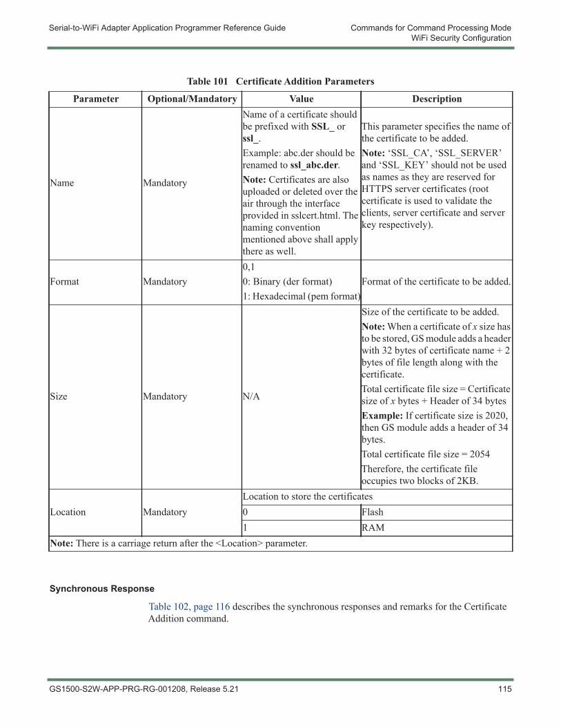
Serial-to-WiFi Adapter Application Programmer Reference Guide Commands for Command Processing ModeWiFi Security Configuration
Synchronous Response
Table 102, page 116 describes the synchronous responses and remarks for the Certificate Addition command.
Table 101 Certificate Addition Parameters
Parameter Optional/Mandatory Value Description
Name Mandatory
Name of a certificate should be prefixed with SSL_ or ssl_.Example: abc.der should be renamed to ssl_abc.der.Note: Certificates are also uploaded or deleted over the air through the interface provided in sslcert.html. The naming convention mentioned above shall apply there as well.
This parameter specifies the name of the certificate to be added.Note: ‘SSL_CA’, ‘SSL_SERVER’ and ‘SSL_KEY’ should not be used as names as they are reserved for HTTPS server certificates (root certificate is used to validate the clients, server certificate and server key respectively).
Format Mandatory0,10: Binary (der format)1: Hexadecimal (pem format)
Format of the certificate to be added.
Size Mandatory N/A
Size of the certificate to be added.Note: When a certificate of x size has to be stored, GS module adds a header with 32 bytes of certificate name + 2 bytes of file length along with the certificate. Total certificate file size = Certificate size of x bytes + Header of 34 bytes Example: If certificate size is 2020, then GS module adds a header of 34 bytes.Total certificate file size = 2054Therefore, the certificate file occupies two blocks of 2KB.
Location MandatoryLocation to store the certificates0 Flash1 RAM
Note: There is a carriage return after the <Location> parameter.
GS1500-S2W-APP-PRG-RG-001208, Release 5.21 115
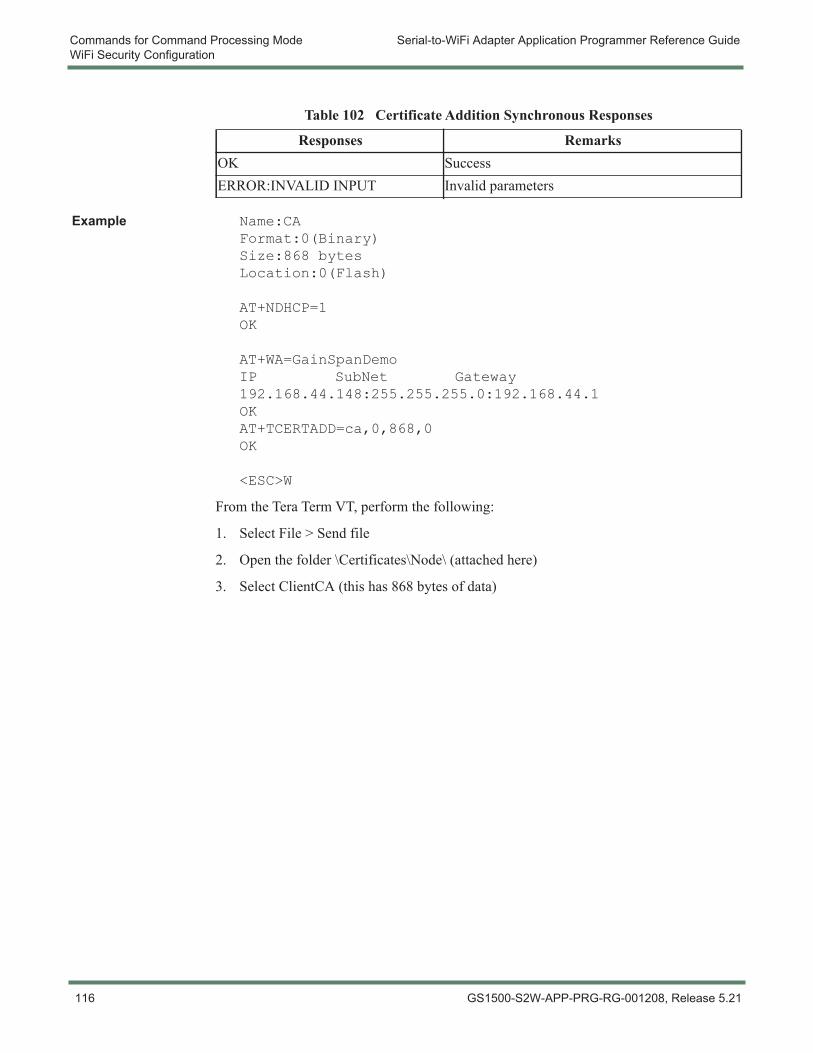
Commands for Command Processing Mode Serial-to-WiFi Adapter Application Programmer Reference GuideWiFi Security Configuration
Example Name:CAFormat:0(Binary)Size:868 bytesLocation:0(Flash)
AT+NDHCP=1OK
AT+WA=GainSpanDemoIP SubNet Gateway192.168.44.148:255.255.255.0:192.168.44.1OKAT+TCERTADD=ca,0,868,0OK
<ESC>W
From the Tera Term VT, perform the following:
1. Select File > Send file
2. Open the folder \Certificates\Node\ (attached here)
3. Select ClientCA (this has 868 bytes of data)
Table 102 Certificate Addition Synchronous Responses
Responses RemarksOK SuccessERROR:INVALID INPUT Invalid parameters
116 GS1500-S2W-APP-PRG-RG-001208, Release 5.21
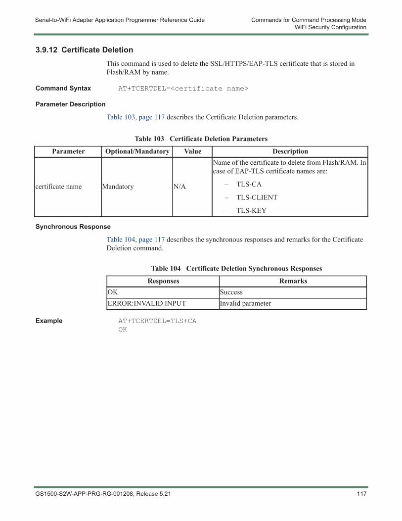
Serial-to-WiFi Adapter Application Programmer Reference Guide Commands for Command Processing ModeWiFi Security Configuration
3.9.12 Certificate DeletionThis command is used to delete the SSL/HTTPS/EAP-TLS certificate that is stored in Flash/RAM by name.
Command Syntax AT+TCERTDEL=<certificate name>
Parameter Description
Table 103, page 117 describes the Certificate Deletion parameters.
Synchronous Response
Table 104, page 117 describes the synchronous responses and remarks for the Certificate Deletion command.
Example AT+TCERTDEL=TLS+CAOK
Table 103 Certificate Deletion Parameters
Parameter Optional/Mandatory Value Description
certificate name Mandatory N/A
Name of the certificate to delete from Flash/RAM. In case of EAP-TLS certificate names are:
– TLS-CA
– TLS-CLIENT
– TLS-KEY
Table 104 Certificate Deletion Synchronous Responses
Responses RemarksOK SuccessERROR:INVALID INPUT Invalid parameter
GS1500-S2W-APP-PRG-RG-001208, Release 5.21 117
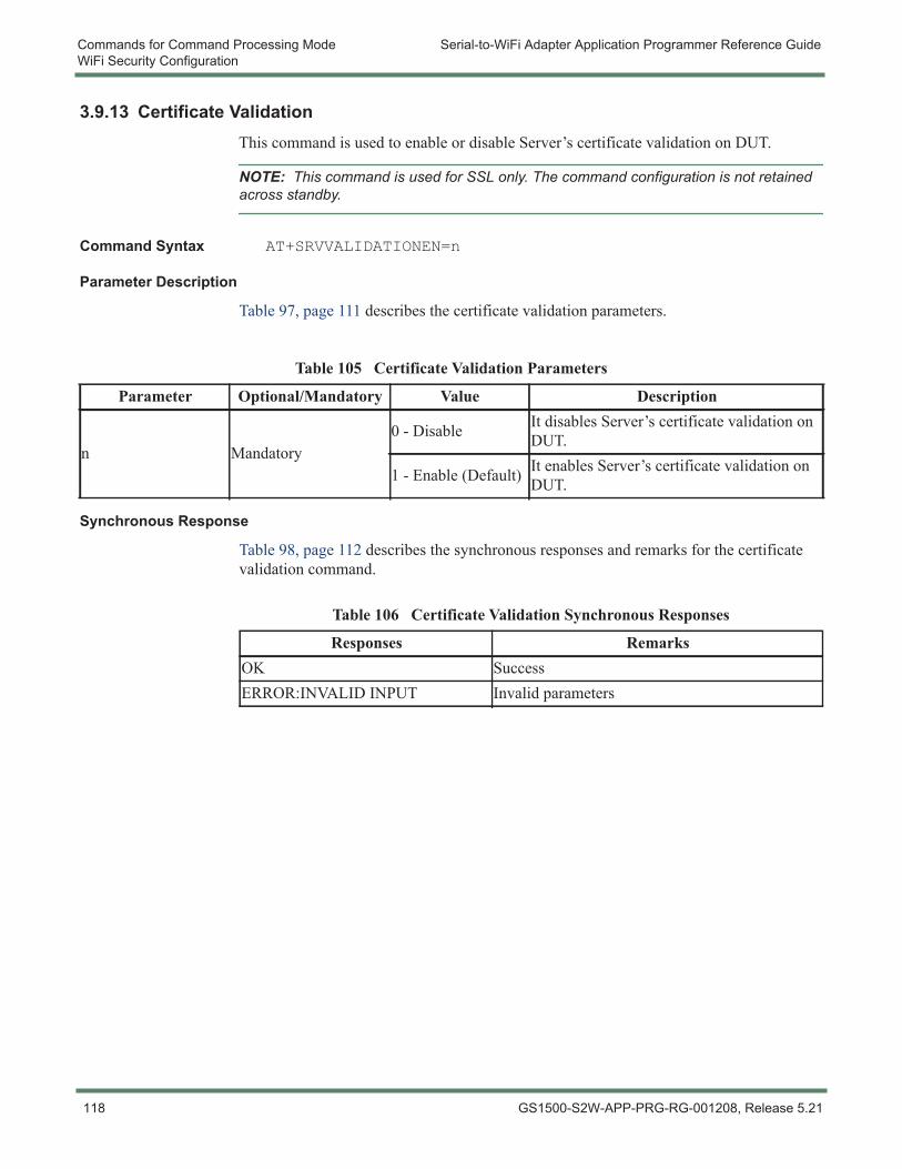
Commands for Command Processing Mode Serial-to-WiFi Adapter Application Programmer Reference GuideWiFi Security Configuration
3.9.13 Certificate ValidationThis command is used to enable or disable Server’s certificate validation on DUT.
NOTE: This command is used for SSL only. The command configuration is not retained across standby.
Command Syntax AT+SRVVALIDATIONEN=n
Parameter Description
Table 97, page 111 describes the certificate validation parameters.
Synchronous Response
Table 98, page 112 describes the synchronous responses and remarks for the certificate validation command.
Table 105 Certificate Validation Parameters
Parameter Optional/Mandatory Value Description
n Mandatory0 - Disable It disables Server’s certificate validation on
DUT.
1 - Enable (Default) It enables Server’s certificate validation on DUT.
Table 106 Certificate Validation Synchronous Responses
Responses RemarksOK SuccessERROR:INVALID INPUT Invalid parameters
118 GS1500-S2W-APP-PRG-RG-001208, Release 5.21
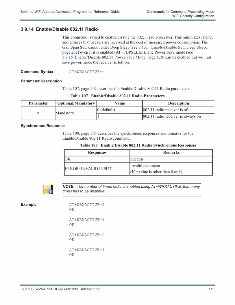
Serial-to-WiFi Adapter Application Programmer Reference Guide Commands for Command Processing ModeWiFi Security Configuration
3.9.14 Enable/Disable 802.11 RadioThis command is used to enable/disable the 802.11 radio receiver. This minimizes latency and ensures that packets are received at the cost of increased power consumption. The GainSpan SoC cannot enter Deep Sleep (see 3.13.1 Enable/Disable SoC Deep Sleep, page 202) even if it is enabled (AT+PDPSLEEP). The Power Save mode (see 3.9.15 Enable/Disable 802.11 Power Save Mode, page 120) can be enabled but will not save power, since the receiver is left on.
Command Syntax AT+WRXACTIVE=n
Parameter Description
Table 107, page 119 describes the Enable/Disable 802.11 Radio parameters.
Synchronous Response
Table 108, page 119 describes the synchronous responses and remarks for the Enable/Disable 802.11 Radio command.
Example AT+WRXACTIVE=1OK
AT+WRXACTIVE=1OK
AT+WRXACTIVE=0OK
AT+WRXACTIVE=1OK
Table 107 Enable/Disable 802.11 Radio Parameters
Parameter Optional/Mandatory Value Description
n Mandatory0 (default) 802.11 radio receiver is off1 802.11 radio receiver is always on
Table 108 Enable/Disable 802.11 Radio Synchronous Responses
Responses RemarksOK Success
ERROR: INVALID INPUTInvalid parameter(If n value is other than 0 or 1)
NOTE: The number of times radio is enabled using AT+WRXACTIVE, that many times has to be disabled.
GS1500-S2W-APP-PRG-RG-001208, Release 5.21 119
Commands for Command Processing Mode Serial-to-WiFi Adapter Application Programmer Reference GuideWiFi Security Configuration
Example Use Case 1 Radio receiver is always on, Power Save mode is enabled but will not save power since the receiver is left on.
AT+WRXACTIVE=1OK
AT+WRXPS=1OK
Example Use Case 2 The receiver is switched off. The node will not receive any packets at this time.AT+WRXACTIVE=0OK
AT+WRXPS=0OK
3.9.15 Enable/Disable 802.11 Power Save ModeThis command is used to enter Power Save Mode. Once enabled, radio will be switched off (after informing AP) when ever possible (e.g., in between beacons intervals, when there is no data transmission). Since module inform up about its inactivity, AP shall buffer all the incoming unicast traffic during this time.
Command Syntax AT+WRXPS=n
Parameter Description
Table 109, page 120 describes the Enable/Disable 802.11 Power Save Mode parameters.
Synchronous Response
Table 110, page 120 describes the synchronous responses and remarks for the Enable/Disable 802.11 Power Save Mode command.
NOTE: Refer to the AT+WIEEEPSPOLL command for 802.11 power save mode.
Table 109 Enable/Disable 802.11 Power Save Mode Parameters
Parameter Optional/Mandatory Value Description
n Mandatory0 Power Save mode is disabled1 (default) Power Save mode is enabled
Table 110 Enable/Disable 802.11 Power Save Mode Synchronous Responses
Responses RemarksOK Success
ERROR:INVALID INPUTIf parameters are not valid(If n value is other than 0 or 1)
120 GS1500-S2W-APP-PRG-RG-001208, Release 5.21
Serial-to-WiFi Adapter Application Programmer Reference Guide Commands for Command Processing ModeWiFi Security Configuration
Example AT+WRXACTIVE=0OK
AT+WRXPS=1OK
Prior to issuing this command the radio should be of (AT+WRXACTIVE=0), otherwise there is no effect of power save, if radio receiver is on.
In this case the node will inform the Access Point that it will go to sleep, and the Access Point will buffer any packets addresses to that node. The node will awaken to listen to periodic beacons from the Access Point that contains a Traffic Indication Map (TIM) that will inform the Station if packets are waiting for it. Buffered packets can be retrieved at that time, using PSPoll commands sent by the node. In this fashion, power consumed by the radio is reduced (although the benefit obtained depends on traffic load and beacon timing), at the cost of some latency. The latency encountered depends in part on the timing of beacons, set by the Access Point configuration. Many Access Points default to 100msec between beacons; in most cases this parameter can be adjusted.
3.9.16 Set Power Save Mode Used During Association
This command is used to configure 802.11 power save mode during the association.
Command Syntax AT+WAPSM=<Value>
Parameter Description
Table 111, page 121 describes the Set Power Save Mode Used During Association parameters.
Table 111 Set Power Save Mode Used During Association Parameters
Parameter Optional/Mandatory Value Description
Value
Mandatory 0
Value to be configured for Power Save Mode. Based on the <value> provided, the following scheme is adopted for power save mode.
Default Radio RX ModeActive Mode(AT+WRACTIVE=1)
PS Poll Mode(AT+WRXPS=1)
OFF
Receiver is kept active ON throughout the joining procedure (default)
GS1500-S2W-APP-PRG-RG-001208, Release 5.21 121
Commands for Command Processing Mode Serial-to-WiFi Adapter Application Programmer Reference GuideWiFi Security Configuration
Synchronous Response
Table 112, page 122 describes the synchronous responses and remarks for the Set Power Save Mode Used During Association command.
Example Use Case The GS node is configured with WPA2 personal security and power save during association is set with the value 1 (Receiver is active ON but turned OFF during the time consuming key calculation during the joining procedure).
AT+WAUTH=0OK
AT+WSEC=8OK
AT+WWPA=admin123OK
Mandatory 1
• Receiver is active ON throughout the joining procedure.
• Receiver is active ON but is in PS Poll mode during the time consuming key calculation during the joining procedure.
• Receiver is active ON but turned OFF during time consuming key calculation during the joining procedure.
Mandatory 2
• Receiver is active ON throughout the joining procedure.
• Receiver is kept PS Poll mode throughout the joining procedure.
• Receiver is kept PS Poll mode throughout the joining procedure.
Mandatory 3
• Receiver is active ON throughout the joining procedure.
• Receiver is kept PS Poll mode throughout the joining procedure.
• Receiver is kept ON in PS Poll mode but turned OFF during time consuming key calculation during the association procedure.
Table 111 Set Power Save Mode Used During Association Parameters (Continued)
Parameter Optional/Mandatory Value Description
Table 112 Set Power Save Mode Used During Association Synchronous Responses
Responses RemarksOK Success
ERROR:INVALID INPUTIf parameters are not valid(If n value is other than 0 -3)
122 GS1500-S2W-APP-PRG-RG-001208, Release 5.21
Serial-to-WiFi Adapter Application Programmer Reference Guide Commands for Command Processing ModeWiFi Security Configuration
AT+WAPSM=1OK
AT+WA=GainSpanDemo,,11IP SubNet Gateway192.168.1.99:255.255.255.0,192.168.1.1OK
AT+NDHCP=1IP SubNet Gateway192.168.23.101:255.255.255.0:192.168.23.1OK
3.9.17 Enable/Disable Multicast ReceptionThis command is used to enable or disable Multicast and Broadcast reception. Multicast and Broadcast are tied together.
Command Syntax AT+MCSTSET=n
Parameter Description
Table 113, page 123 describes the Enable/Disable Multicast Reception parameters.
Synchronous Response
Table 113 Enable/Disable Multicast Reception Parameters
Parameter Optional/Mandatory Value Description
n Mandatory
0
Disable802.11 MAC layer multicast + broadcast reception is disabled.Reception of all higher layer (IP and above) multicast and broadcast packets are disabled by AT+MCSTSET=0 option. When disabled, the ability for the node to receive higher layer broadcast traffic such as ARP responses that are needed to establish IP layer communication is also disabled.
1 (default)
Enable802.11 MAC layer multicast + broadcast reception is enabled.Reception of all higher layer (IP and above) multicast and broadcast packets is enabled by “AT+MCSTSET=1” option. The MCU will receive/transmit the multicast and broadcast packets by opening the UDP sockets using the command “AT+NCUDP” (see 3.11.4 UDP Clients for IPv4, page 167 or 3.11.5 TCP Servers for IPv4, page 168).
GS1500-S2W-APP-PRG-RG-001208, Release 5.21 123
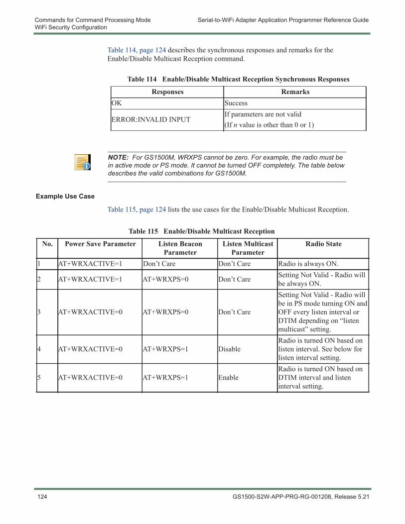
Commands for Command Processing Mode Serial-to-WiFi Adapter Application Programmer Reference GuideWiFi Security Configuration
Table 114, page 124 describes the synchronous responses and remarks for the Enable/Disable Multicast Reception command.
Example Use Case
Table 115, page 124 lists the use cases for the Enable/Disable Multicast Reception.
Table 114 Enable/Disable Multicast Reception Synchronous Responses
Responses RemarksOK Success
ERROR:INVALID INPUTIf parameters are not valid(If n value is other than 0 or 1)
NOTE: For GS1500M, WRXPS cannot be zero. For example, the radio must be in active mode or PS mode. It cannot be turned OFF completely. The table below describes the valid combinations for GS1500M.
Table 115 Enable/Disable Multicast Reception
No. Power Save Parameter Listen Beacon Parameter
Listen Multicast Parameter
Radio State
1 AT+WRXACTIVE=1 Don’t Care Don’t Care Radio is always ON.
2 AT+WRXACTIVE=1 AT+WRXPS=0 Don’t Care Setting Not Valid - Radio will be always ON.
3 AT+WRXACTIVE=0 AT+WRXPS=0 Don’t Care
Setting Not Valid - Radio will be in PS mode turning ON and OFF every listen interval or DTIM depending on “listen multicast” setting.
4 AT+WRXACTIVE=0 AT+WRXPS=1 DisableRadio is turned ON based on listen interval. See below for listen interval setting.
5 AT+WRXACTIVE=0 AT+WRXPS=1 EnableRadio is turned ON based on DTIM interval and listen interval setting.
124 GS1500-S2W-APP-PRG-RG-001208, Release 5.21
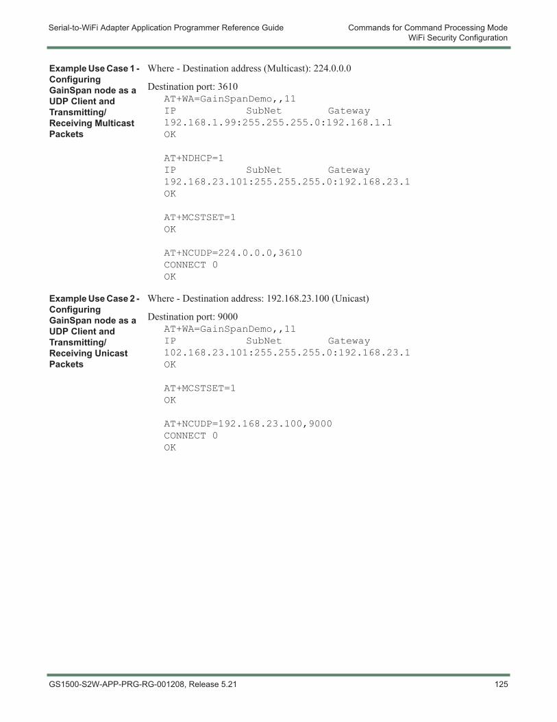
Serial-to-WiFi Adapter Application Programmer Reference Guide Commands for Command Processing ModeWiFi Security Configuration
Example Use Case 1 - Configuring GainSpan node as a UDP Client and Transmitting/Receiving Multicast Packets
Where - Destination address (Multicast): 224.0.0.0
Destination port: 3610AT+WA=GainSpanDemo,,11IP SubNet Gateway192.168.1.99:255.255.255.0:192.168.1.1OK
AT+NDHCP=1IP SubNet Gateway192.168.23.101:255.255.255.0:192.168.23.1OK
AT+MCSTSET=1OK
AT+NCUDP=224.0.0.0,3610CONNECT 0OK
Example Use Case 2 - Configuring GainSpan node as a UDP Client and Transmitting/Receiving Unicast Packets
Where - Destination address: 192.168.23.100 (Unicast)
Destination port: 9000AT+WA=GainSpanDemo,,11IP SubNet Gateway102.168.23.101:255.255.255.0:192.168.23.1OK
AT+MCSTSET=1OK
AT+NCUDP=192.168.23.100,9000CONNECT 0OK
GS1500-S2W-APP-PRG-RG-001208, Release 5.21 125
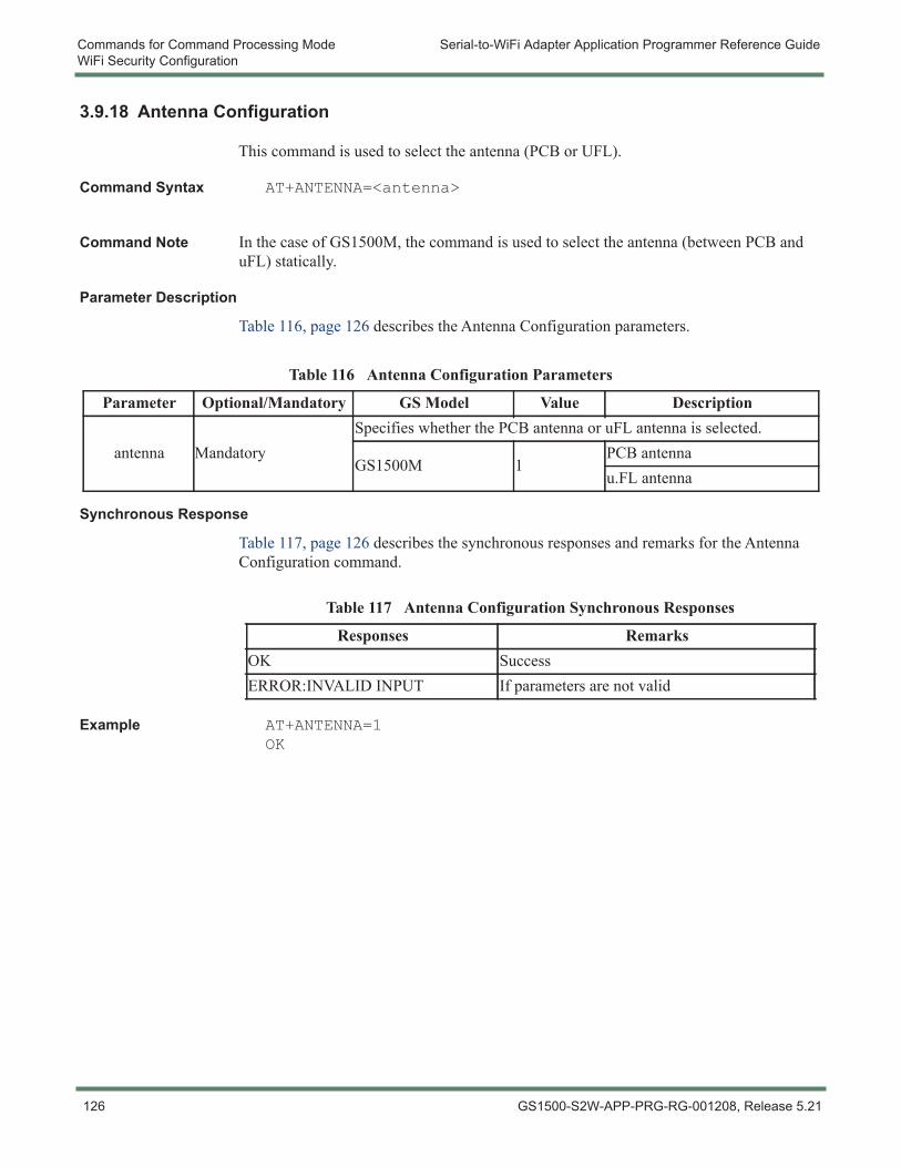
Commands for Command Processing Mode Serial-to-WiFi Adapter Application Programmer Reference GuideWiFi Security Configuration
3.9.18 Antenna Configuration
This command is used to select the antenna (PCB or UFL).
Command Syntax AT+ANTENNA=<antenna>
Command Note In the case of GS1500M, the command is used to select the antenna (between PCB and uFL) statically.
Parameter Description
Table 116, page 126 describes the Antenna Configuration parameters.
Synchronous Response
Table 117, page 126 describes the synchronous responses and remarks for the Antenna Configuration command.
Example AT+ANTENNA=1OK
Table 116 Antenna Configuration Parameters
Parameter Optional/Mandatory GS Model Value Description
antenna MandatorySpecifies whether the PCB antenna or uFL antenna is selected.
GS1500M 1PCB antennau.FL antenna
Table 117 Antenna Configuration Synchronous Responses
Responses RemarksOK SuccessERROR:INVALID INPUT If parameters are not valid
126 GS1500-S2W-APP-PRG-RG-001208, Release 5.21
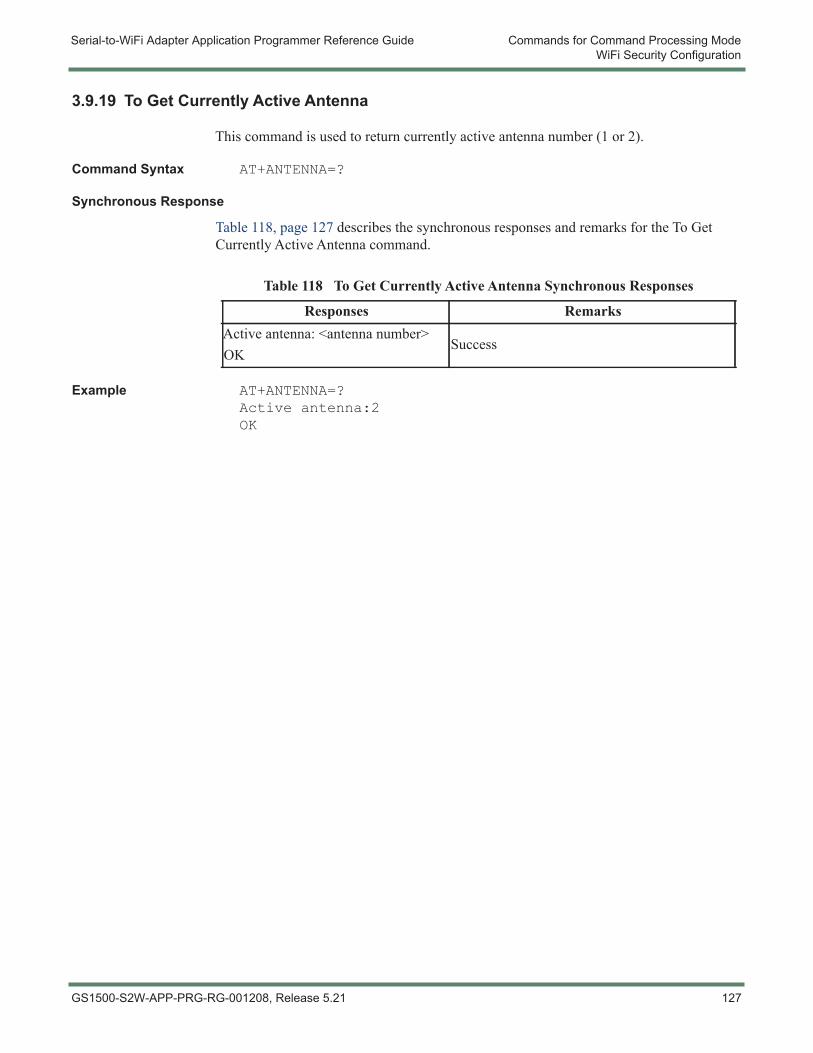
Serial-to-WiFi Adapter Application Programmer Reference Guide Commands for Command Processing ModeWiFi Security Configuration
3.9.19 To Get Currently Active Antenna
This command is used to return currently active antenna number (1 or 2).
Command Syntax AT+ANTENNA=?
Synchronous Response
Table 118, page 127 describes the synchronous responses and remarks for the To Get Currently Active Antenna command.
Example AT+ANTENNA=?Active antenna:2OK
Table 118 To Get Currently Active Antenna Synchronous Responses
Responses RemarksActive antenna: <antenna number>OK
Success
GS1500-S2W-APP-PRG-RG-001208, Release 5.21 127
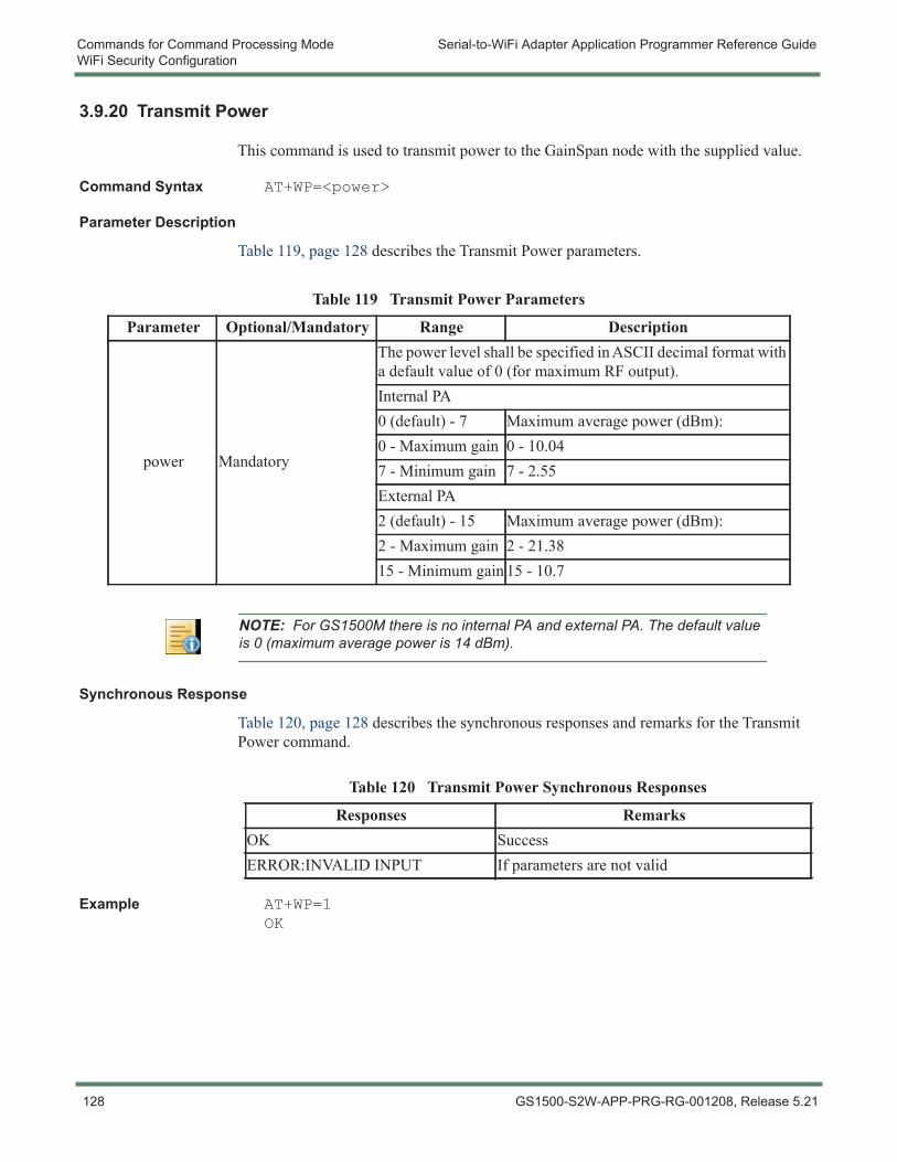
Commands for Command Processing Mode Serial-to-WiFi Adapter Application Programmer Reference GuideWiFi Security Configuration
3.9.20 Transmit Power
This command is used to transmit power to the GainSpan node with the supplied value.
Command Syntax AT+WP=<power>
Parameter Description
Table 119, page 128 describes the Transmit Power parameters.
Synchronous Response
Table 120, page 128 describes the synchronous responses and remarks for the Transmit Power command.
Example AT+WP=1OK
Table 119 Transmit Power Parameters
Parameter Optional/Mandatory Range Description
power Mandatory
The power level shall be specified in ASCII decimal format with a default value of 0 (for maximum RF output).Internal PA0 (default) - 7 Maximum average power (dBm):0 - Maximum gain 0 - 10.047 - Minimum gain 7 - 2.55External PA2 (default) - 15 Maximum average power (dBm):2 - Maximum gain 2 - 21.3815 - Minimum gain 15 - 10.7
NOTE: For GS1500M there is no internal PA and external PA. The default value is 0 (maximum average power is 14 dBm).
Table 120 Transmit Power Synchronous Responses
Responses RemarksOK SuccessERROR:INVALID INPUT If parameters are not valid
128 GS1500-S2W-APP-PRG-RG-001208, Release 5.21
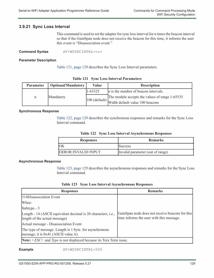
Serial-to-WiFi Adapter Application Programmer Reference Guide Commands for Command Processing ModeWiFi Security Configuration
3.9.21 Sync Loss IntervalThis command is used to set the adapter for sync loss interval for n times the beacon interval so that if the GainSpan node does not receive the beacon for this time, it informs the user this event is “Disassociation event.”
Command Syntax AT+WSYNCINTRL=<n>
Parameter Description
Table 121, page 129 describes the Sync Loss Interval parameters.
Synchronous Response
Table 122, page 129 describes the synchronous responses and remarks for the Sync Loss Interval command.
Asynchronous Response
Table 123, page 129 describes the asynchronous responses and remarks for the Sync Loss Interval command.
Example AT+WSYNCINTRL=500
Table 121 Sync Loss Interval Parameters
Parameter Optional/Mandatory Value Description
n Mandatory1-63325 n is the number of beacon intervals.
The module accepts the values of range 1-65535Width default value 100 beacons
100 (default)
Table 122 Sync Loss Interval Asynchronous Responses
Responses RemarksOK SuccessERROR:INVALID INPUT Invalid parameter (out of range)
Table 123 Sync Loss Interval Asynchronous Responses
Responses Remarks314Disassociation EventWhee:Subtype - 3Length - 14 (ASCII equivalent decimal is 20 characters, i.e., length of the actual message)Actual message - Disassociation EventThe type of message. Length is 1 byte. for asynchronous message, it is 0x41 (ASCII value A).
GainSpan node does not receive beacons for this time informs the user with this message.
Note: <ESC> and Type is not displayed because its Tera Term issue.
GS1500-S2W-APP-PRG-RG-001208, Release 5.21 129
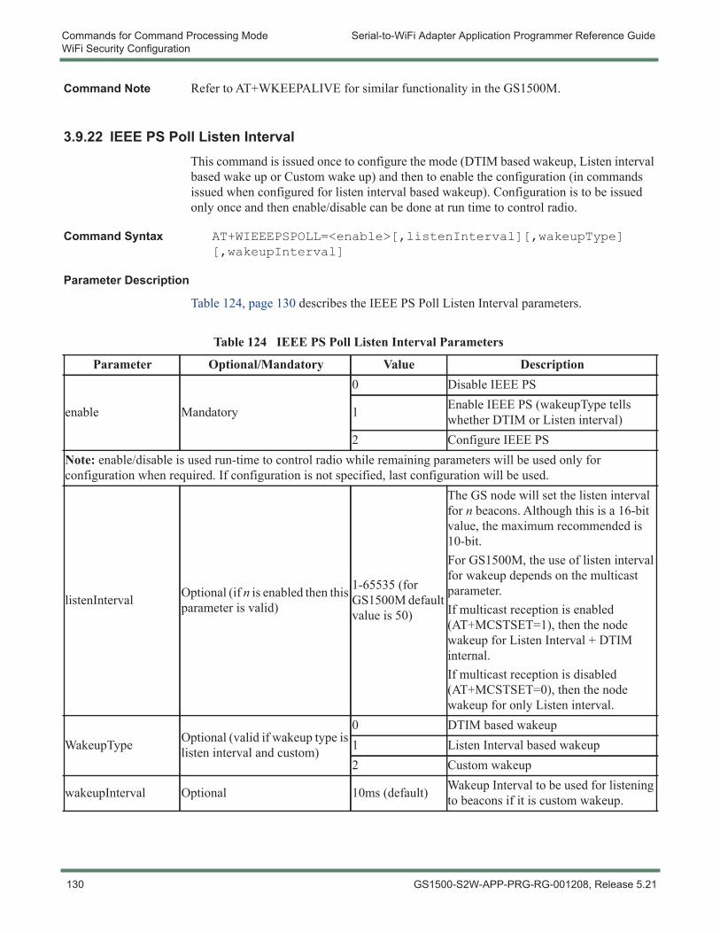
Commands for Command Processing Mode Serial-to-WiFi Adapter Application Programmer Reference GuideWiFi Security Configuration
Command Note Refer to AT+WKEEPALIVE for similar functionality in the GS1500M.
3.9.22 IEEE PS Poll Listen IntervalThis command is issued once to configure the mode (DTIM based wakeup, Listen interval based wake up or Custom wake up) and then to enable the configuration (in commands issued when configured for listen interval based wakeup). Configuration is to be issued only once and then enable/disable can be done at run time to control radio.
Command Syntax AT+WIEEEPSPOLL=<enable>[,listenInterval][,wakeupType][,wakeupInterval]
Parameter Description
Table 124, page 130 describes the IEEE PS Poll Listen Interval parameters.
Table 124 IEEE PS Poll Listen Interval Parameters
Parameter Optional/Mandatory Value Description
enable Mandatory
0 Disable IEEE PS
1 Enable IEEE PS (wakeupType tells whether DTIM or Listen interval)
2 Configure IEEE PSNote: enable/disable is used run-time to control radio while remaining parameters will be used only for configuration when required. If configuration is not specified, last configuration will be used.
listenInterval Optional (if n is enabled then this parameter is valid)
1-65535 (for GS1500M default value is 50)
The GS node will set the listen interval for n beacons. Although this is a 16-bit value, the maximum recommended is 10-bit.For GS1500M, the use of listen interval for wakeup depends on the multicast parameter.If multicast reception is enabled (AT+MCSTSET=1), then the node wakeup for Listen Interval + DTIM internal.If multicast reception is disabled (AT+MCSTSET=0), then the node wakeup for only Listen interval.
WakeupType Optional (valid if wakeup type is listen interval and custom)
0 DTIM based wakeup1 Listen Interval based wakeup2 Custom wakeup
wakeupInterval Optional 10ms (default) Wakeup Interval to be used for listening to beacons if it is custom wakeup.
130 GS1500-S2W-APP-PRG-RG-001208, Release 5.21

Serial-to-WiFi Adapter Application Programmer Reference Guide Commands for Command Processing ModeWiFi Security Configuration
Example - AT+WRXACTIVE
If AT+WRXACTIVE = 1, then the radio is always ON. No power save is done in this case. Regardless of what the parameters for the other two commands are, the radio will receive all the packets. Rest of the commands are “Don’t Care.”
Example - AT+WRXPS
If AT+WRXPS = 1, Regardless of what the parameters for AT+WIEEEPSPOLL are, the STA will wake up for every beacon. AT+WIEEEPSPOLL is a “Don’t Care” in this case.
If AT+WRXPS = 0, the STA will not wake up for every beacon. Based on the AT+WIEEEPSPOLL, the wake will be decided as explained further.
Example - AT+WIEEEPSPOLL
This command can be used for three purposes:
– To configure the Power Save behavior
– To Enable the Power Save
– To Disable the Power Save
Usage - Configuration of Power Save
To configure the Power Save behavior on the STA, the first parameter of the command should be 2. The STA can be configured in 3 ways:
– Wake up for Listen Interval
– Wake up for DTIM
– Wake up for a custom number of beacons
Wake up for Listen Interval
To configure the STA to wake up for the listen interval, the command is AT+WIEEEPSPOLL=2,10,1. This means that the STA will advertise in the Association Request that the listen interval will be for every 10 beacons. Once associated, the STA will wake up for every 10 beacons.
Wake up for DTIM To configure the STA to wake up for every DTIM interval, the command is AT+WIEEEPSPOLL=2,,0. Here we did not specify the listen interval as that will be the default. In this case, the STA will advertise the default Listen Interval in the Association Request. Once associated, the STA will wake up for every DTIM interval that has been configured on the AP.
Custom Wake up To configure the STA to wake up at a custom interval, the command is AT+WIEEEPSPOLL=2,,2,5. Here also, we did not specify the listen interval, that will be the default. The STA will advertise the default Listen Interval in the Association Request. Once associated, the STA will wake up for every 5 beacons.
Difference between Listen Interval based Wake up Versus Custom Wake up
At the outset, both of these options do the same thing - to wake the STA based on the number of beacons given.
Either of these options can be used to wake the STA. However, the use case is as follows:
Example Use Case Whenever the STA is needed to wake up at some configured interval, the Custom Wake up option should be used. While configuring the custom wake up parameters, the listen interval should not be entered; the default listen interval will be used in the association request. Usually, in the association request, the STA will advertise the listen interval as a large value (e.g., 10 beacons). The configuration of the custom wake up interval will be less than the listen interval (e.g., 5 beacons). In this case, the STA bluffs to the AP while
GS1500-S2W-APP-PRG-RG-001208, Release 5.21 131

Commands for Command Processing Mode Serial-to-WiFi Adapter Application Programmer Reference GuideWiFi Security Configuration
associating telling that it will wake up for every 10 beacons. But, in reality, it will wake up for every 5 beacons. This is just to ensure that the AP shouldn’t drop the buffered frames in case the PS Poll request from the STA does not reach the AP.
Enable Power Save To enable the power save on the STA, the command is AT+WIEEEPSPOLL=1. Whenever AT+WIEEEPSPOLL is given as 1, the STA will take the last power save configuration into effect. So, the user should first configure the behavior and then enable the power save.
Disable Power Save To disable the power save on the STA, the command is AT+WIEEEPSPOLL=0. When this command is executed, the radio is fully off. Order of Precedence between commands - WRXACTIVE > WRXPS > WIEEEPSPOLL.
Command Note If the power save behavior is changed after the association is done, the new changes will take into effect only for the next association.
132 GS1500-S2W-APP-PRG-RG-001208, Release 5.21
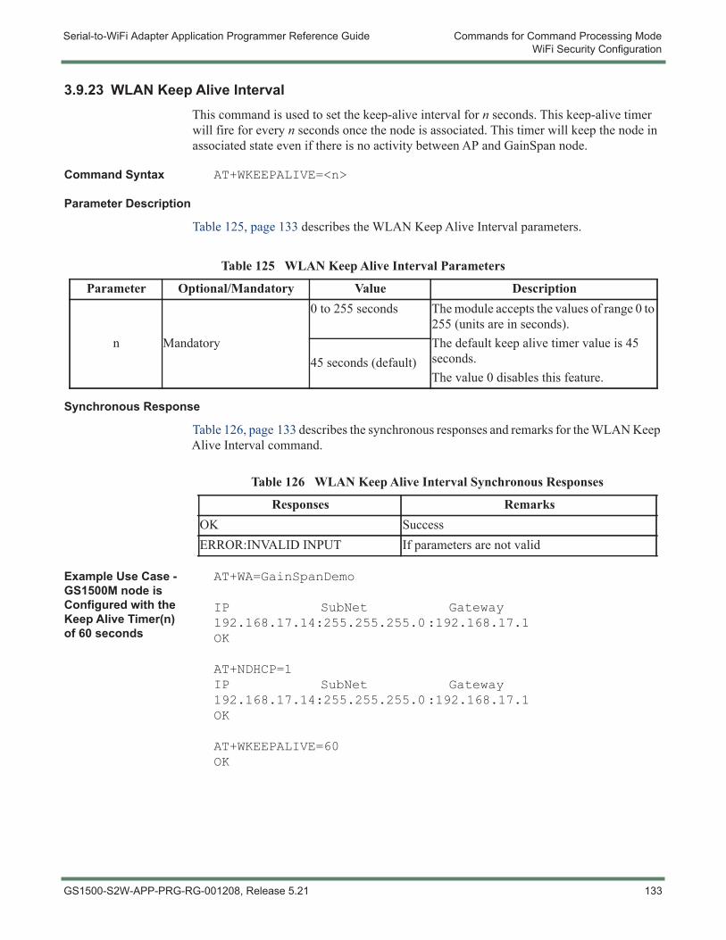
Serial-to-WiFi Adapter Application Programmer Reference Guide Commands for Command Processing ModeWiFi Security Configuration
3.9.23 WLAN Keep Alive IntervalThis command is used to set the keep-alive interval for n seconds. This keep-alive timer will fire for every n seconds once the node is associated. This timer will keep the node in associated state even if there is no activity between AP and GainSpan node.
Command Syntax AT+WKEEPALIVE=<n>
Parameter Description
Table 125, page 133 describes the WLAN Keep Alive Interval parameters.
Synchronous Response
Table 126, page 133 describes the synchronous responses and remarks for the WLAN Keep Alive Interval command.
Example Use Case - GS1500M node is Configured with the Keep Alive Timer(n) of 60 seconds
AT+WA=GainSpanDemo
IP SubNet Gateway192.168.17.14:255.255.255.0:192.168.17.1OK
AT+NDHCP=1IP SubNet Gateway192.168.17.14:255.255.255.0:192.168.17.1OK
AT+WKEEPALIVE=60OK
Table 125 WLAN Keep Alive Interval Parameters
Parameter Optional/Mandatory Value Description
n Mandatory
0 to 255 seconds The module accepts the values of range 0 to 255 (units are in seconds).The default keep alive timer value is 45 seconds.The value 0 disables this feature.
45 seconds (default)
Table 126 WLAN Keep Alive Interval Synchronous Responses
Responses RemarksOK SuccessERROR:INVALID INPUT If parameters are not valid
GS1500-S2W-APP-PRG-RG-001208, Release 5.21 133
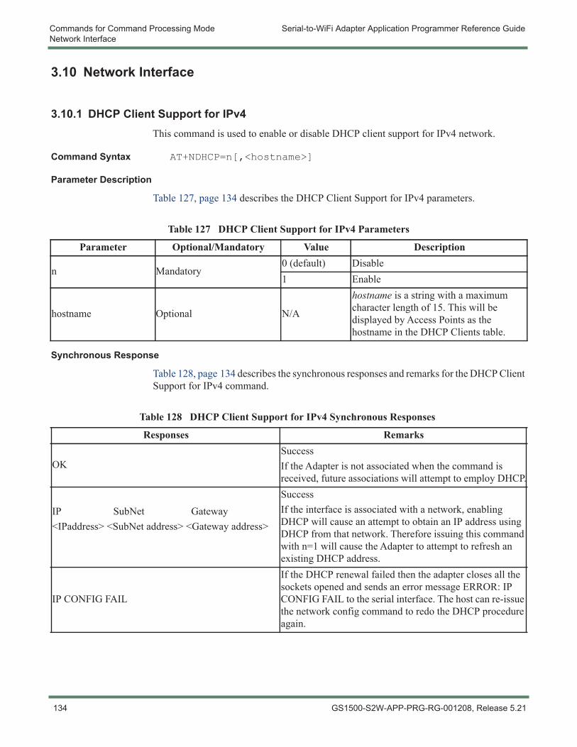
Commands for Command Processing Mode Serial-to-WiFi Adapter Application Programmer Reference GuideNetwork Interface
3.10 Network Interface
3.10.1 DHCP Client Support for IPv4This command is used to enable or disable DHCP client support for IPv4 network.
Command Syntax AT+NDHCP=n[,<hostname>]
Parameter Description
Table 127, page 134 describes the DHCP Client Support for IPv4 parameters.
Synchronous Response
Table 128, page 134 describes the synchronous responses and remarks for the DHCP Client Support for IPv4 command.
Table 127 DHCP Client Support for IPv4 Parameters
Parameter Optional/Mandatory Value Description
n Mandatory0 (default) Disable1 Enable
hostname Optional N/A
hostname is a string with a maximum character length of 15. This will be displayed by Access Points as the hostname in the DHCP Clients table.
Table 128 DHCP Client Support for IPv4 Synchronous Responses
Responses Remarks
OKSuccessIf the Adapter is not associated when the command is received, future associations will attempt to employ DHCP.
IP SubNet Gateway<IPaddress> <SubNet address> <Gateway address>
SuccessIf the interface is associated with a network, enabling DHCP will cause an attempt to obtain an IP address using DHCP from that network. Therefore issuing this command with n=1 will cause the Adapter to attempt to refresh an existing DHCP address.
IP CONFIG FAIL
If the DHCP renewal failed then the adapter closes all the sockets opened and sends an error message ERROR: IP CONFIG FAIL to the serial interface. The host can re-issue the network config command to redo the DHCP procedure again.
134 GS1500-S2W-APP-PRG-RG-001208, Release 5.21
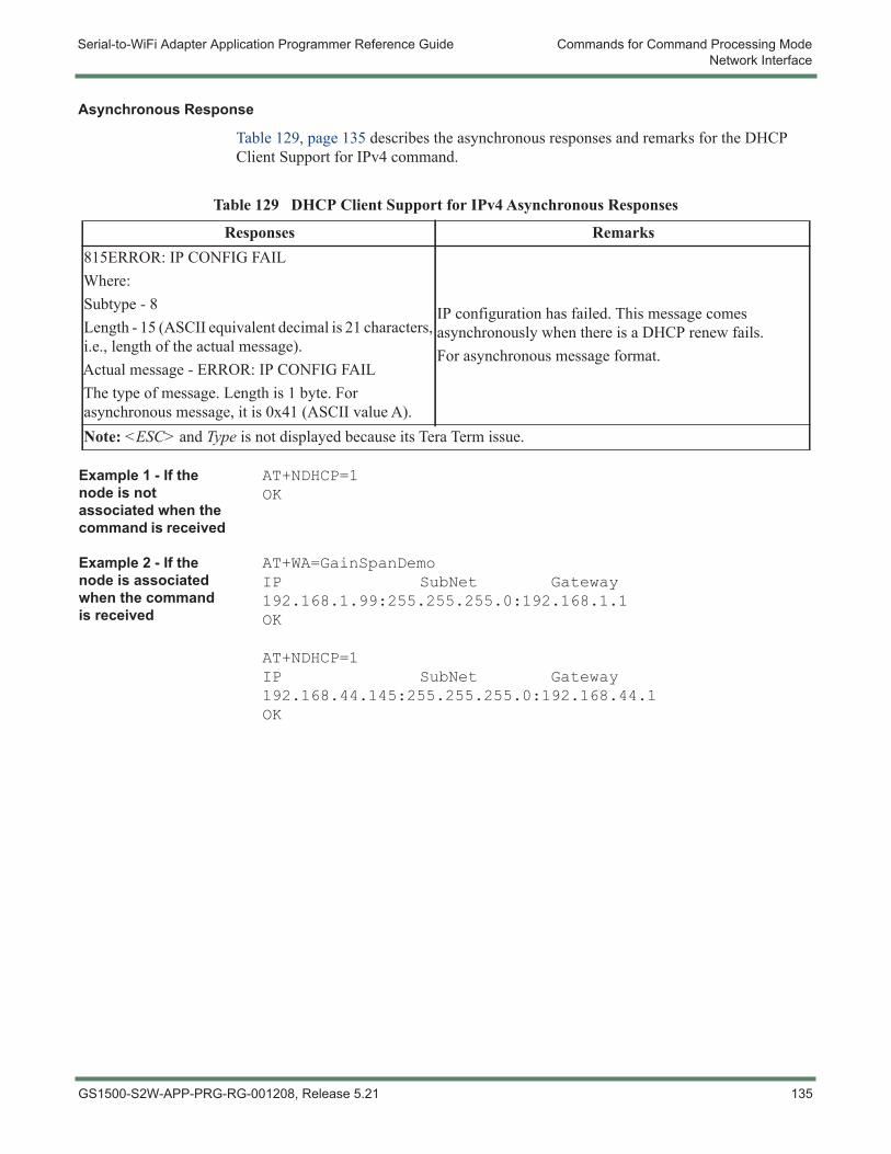
Serial-to-WiFi Adapter Application Programmer Reference Guide Commands for Command Processing ModeNetwork Interface
Asynchronous Response
Table 129, page 135 describes the asynchronous responses and remarks for the DHCP Client Support for IPv4 command.
Example 1 - If the node is not associated when the command is received
AT+NDHCP=1OK
Example 2 - If the node is associated when the command is received
AT+WA=GainSpanDemoIP SubNet Gateway192.168.1.99:255.255.255.0:192.168.1.1OK
AT+NDHCP=1IP SubNet Gateway192.168.44.145:255.255.255.0:192.168.44.1OK
Table 129 DHCP Client Support for IPv4 Asynchronous Responses
Responses Remarks815ERROR: IP CONFIG FAILWhere:Subtype - 8Length - 15 (ASCII equivalent decimal is 21 characters, i.e., length of the actual message).Actual message - ERROR: IP CONFIG FAILThe type of message. Length is 1 byte. For asynchronous message, it is 0x41 (ASCII value A).
IP configuration has failed. This message comes asynchronously when there is a DHCP renew fails.For asynchronous message format.
Note: <ESC> and Type is not displayed because its Tera Term issue.
GS1500-S2W-APP-PRG-RG-001208, Release 5.21 135
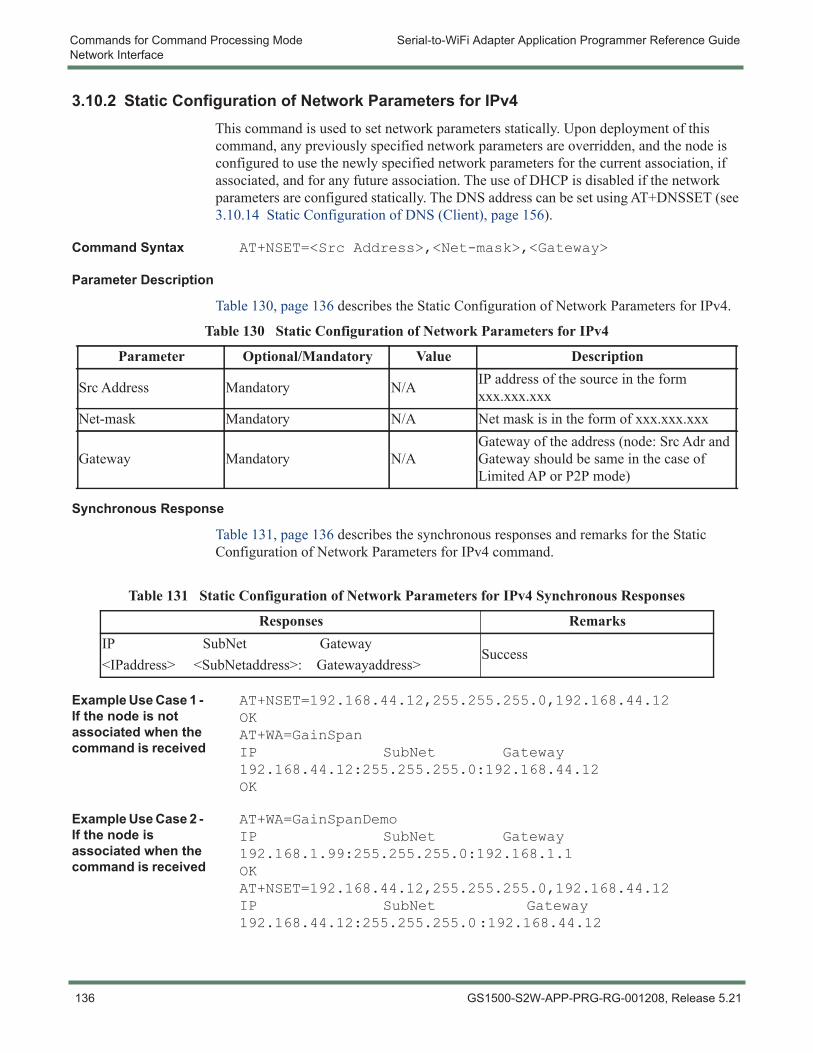
Commands for Command Processing Mode Serial-to-WiFi Adapter Application Programmer Reference GuideNetwork Interface
3.10.2 Static Configuration of Network Parameters for IPv4This command is used to set network parameters statically. Upon deployment of this command, any previously specified network parameters are overridden, and the node is configured to use the newly specified network parameters for the current association, if associated, and for any future association. The use of DHCP is disabled if the network parameters are configured statically. The DNS address can be set using AT+DNSSET (see 3.10.14 Static Configuration of DNS (Client), page 156).
Command Syntax AT+NSET=<Src Address>,<Net-mask>,<Gateway>
Parameter Description
Table 130, page 136 describes the Static Configuration of Network Parameters for IPv4.
Synchronous Response
Table 131, page 136 describes the synchronous responses and remarks for the Static Configuration of Network Parameters for IPv4 command.
Example Use Case 1 - If the node is not associated when the command is received
AT+NSET=192.168.44.12,255.255.255.0,192.168.44.12OKAT+WA=GainSpanIP SubNet Gateway192.168.44.12:255.255.255.0:192.168.44.12OK
Example Use Case 2 - If the node is associated when the command is received
AT+WA=GainSpanDemoIP SubNet Gateway192.168.1.99:255.255.255.0:192.168.1.1OKAT+NSET=192.168.44.12,255.255.255.0,192.168.44.12IP SubNet Gateway192.168.44.12:255.255.255.0:192.168.44.12
Table 130 Static Configuration of Network Parameters for IPv4
Parameter Optional/Mandatory Value Description
Src Address Mandatory N/A IP address of the source in the form xxx.xxx.xxx
Net-mask Mandatory N/A Net mask is in the form of xxx.xxx.xxx
Gateway Mandatory N/AGateway of the address (node: Src Adr and Gateway should be same in the case of Limited AP or P2P mode)
Table 131 Static Configuration of Network Parameters for IPv4 Synchronous Responses
Responses RemarksIP SubNet Gateway<IPaddress> <SubNetaddress>: Gatewayaddress>
Success
136 GS1500-S2W-APP-PRG-RG-001208, Release 5.21
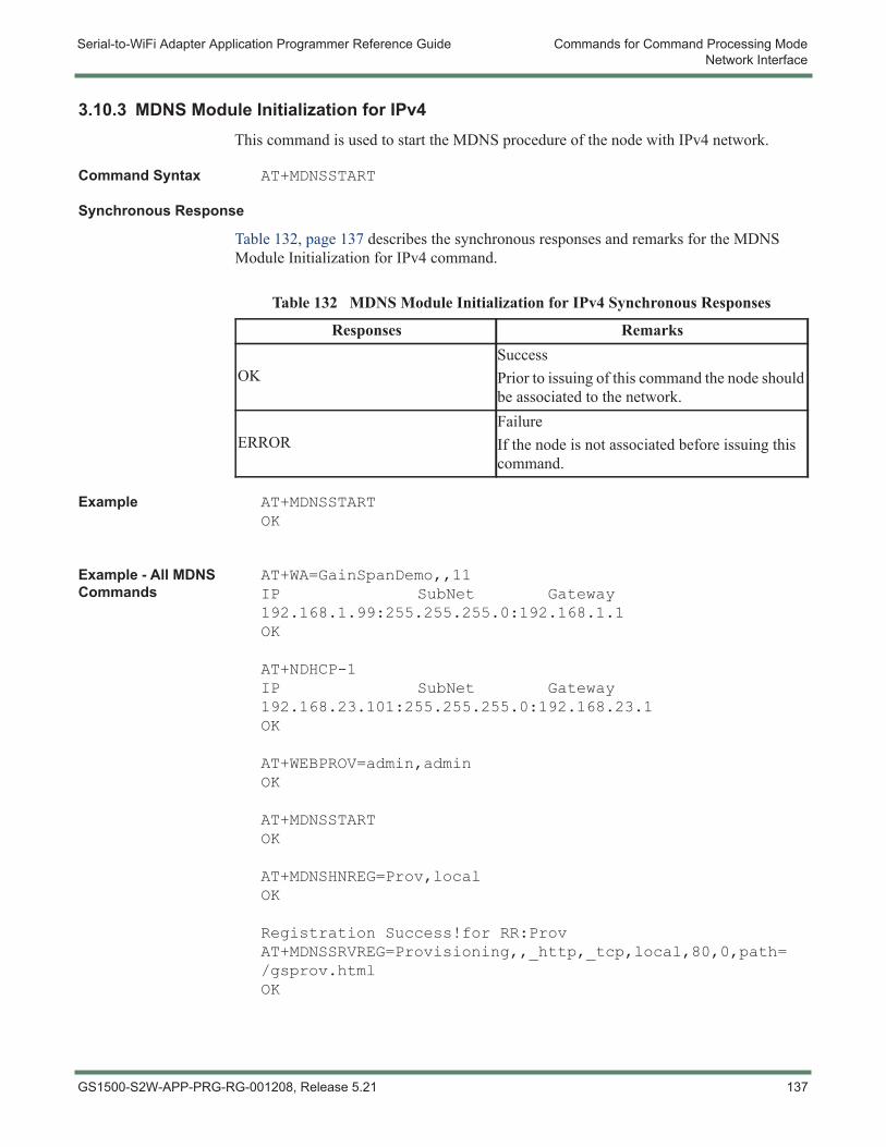
Serial-to-WiFi Adapter Application Programmer Reference Guide Commands for Command Processing ModeNetwork Interface
3.10.3 MDNS Module Initialization for IPv4This command is used to start the MDNS procedure of the node with IPv4 network.
Command Syntax AT+MDNSSTART
Synchronous Response
Table 132, page 137 describes the synchronous responses and remarks for the MDNS Module Initialization for IPv4 command.
Example AT+MDNSSTARTOK
Example - All MDNS Commands
AT+WA=GainSpanDemo,,11IP SubNet Gateway192.168.1.99:255.255.255.0:192.168.1.1OK
AT+NDHCP-1IP SubNet Gateway192.168.23.101:255.255.255.0:192.168.23.1OK
AT+WEBPROV=admin,adminOK
AT+MDNSSTARTOK
AT+MDNSHNREG=Prov,localOK
Registration Success!for RR:ProvAT+MDNSSRVREG=Provisioning,,_http,_tcp,local,80,0,path=/gsprov.htmlOK
Table 132 MDNS Module Initialization for IPv4 Synchronous Responses
Responses Remarks
OKSuccessPrior to issuing of this command the node should be associated to the network.
ERRORFailureIf the node is not associated before issuing this command.
GS1500-S2W-APP-PRG-RG-001208, Release 5.21 137
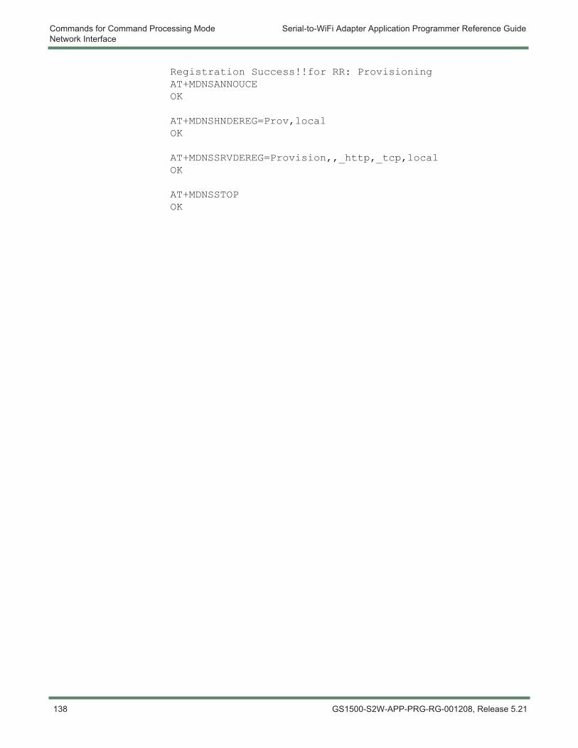
Commands for Command Processing Mode Serial-to-WiFi Adapter Application Programmer Reference GuideNetwork Interface
Registration Success!!for RR: ProvisioningAT+MDNSANNOUCEOK
AT+MDNSHNDEREG=Prov,localOK
AT+MDNSSRVDEREG=Provision,,_http,_tcp,localOK
AT+MDNSSTOPOK
138 GS1500-S2W-APP-PRG-RG-001208, Release 5.21
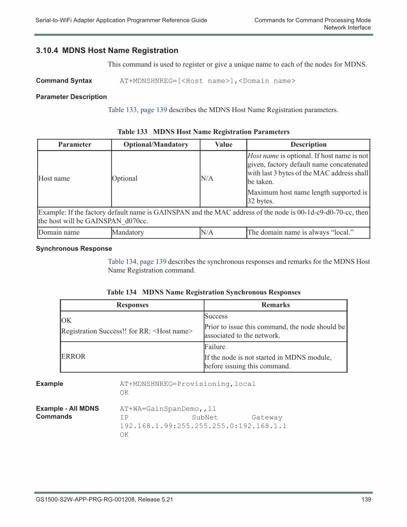
Serial-to-WiFi Adapter Application Programmer Reference Guide Commands for Command Processing ModeNetwork Interface
3.10.4 MDNS Host Name RegistrationThis command is used to register or give a unique name to each of the nodes for MDNS.
Command Syntax AT+MDNSHNREG=[<Host name>],<Domain name>
Parameter Description
Table 133, page 139 describes the MDNS Host Name Registration parameters.
Synchronous Response
Table 134, page 139 describes the synchronous responses and remarks for the MDNS Host Name Registration command.
Example AT+MDNSHNREG=Provisioning,localOK
Example - All MDNS Commands
AT+WA=GainSpanDemo,,11IP SubNet Gateway192.168.1.99:255.255.255.0:192.168.1.1OK
Table 133 MDNS Host Name Registration Parameters
Parameter Optional/Mandatory Value Description
Host name Optional N/A
Host name is optional. If host name is not given, factory default name concatenated with last 3 bytes of the MAC address shall be taken.Maximum host name length supported is 32 bytes.
Example: If the factory default name is GAINSPAN and the MAC address of the node is 00-1d-c9-d0-70-cc, then the host will be GAINSPAN_d070cc.Domain name Mandatory N/A The domain name is always “local.”
Table 134 MDNS Name Registration Synchronous Responses
Responses Remarks
OKRegistration Success!! for RR: <Host name>
SuccessPrior to issue this command, the node should be associated to the network.
ERRORFailureIf the node is not started in MDNS module, before issuing this command.
GS1500-S2W-APP-PRG-RG-001208, Release 5.21 139

Commands for Command Processing Mode Serial-to-WiFi Adapter Application Programmer Reference GuideNetwork Interface
AT+NDHCP-1IP SubNet Gateway192.168.23.101:255.255.255.0:192.168.23.1OK
AT+WEBPROV=admin,adminOK
AT+MDNSSTARTOK
AT+MDNSHNREG=Prov,localOK
Registration Success!for RR:ProvAT+MDNSSRVREG=Provisioning,,_http,_tcp,local,80,0,path=/gsprov.htmlOK
Registration Success!!for RR: ProvisioningAT+MDNSANNOUCEOK
AT+MDNSHNDEREG=Prov,localOK
AT+MDNSSRVDEREG=Provision,,_http,_tcp,localOK
AT+MDNSSTOPOK
140 GS1500-S2W-APP-PRG-RG-001208, Release 5.21
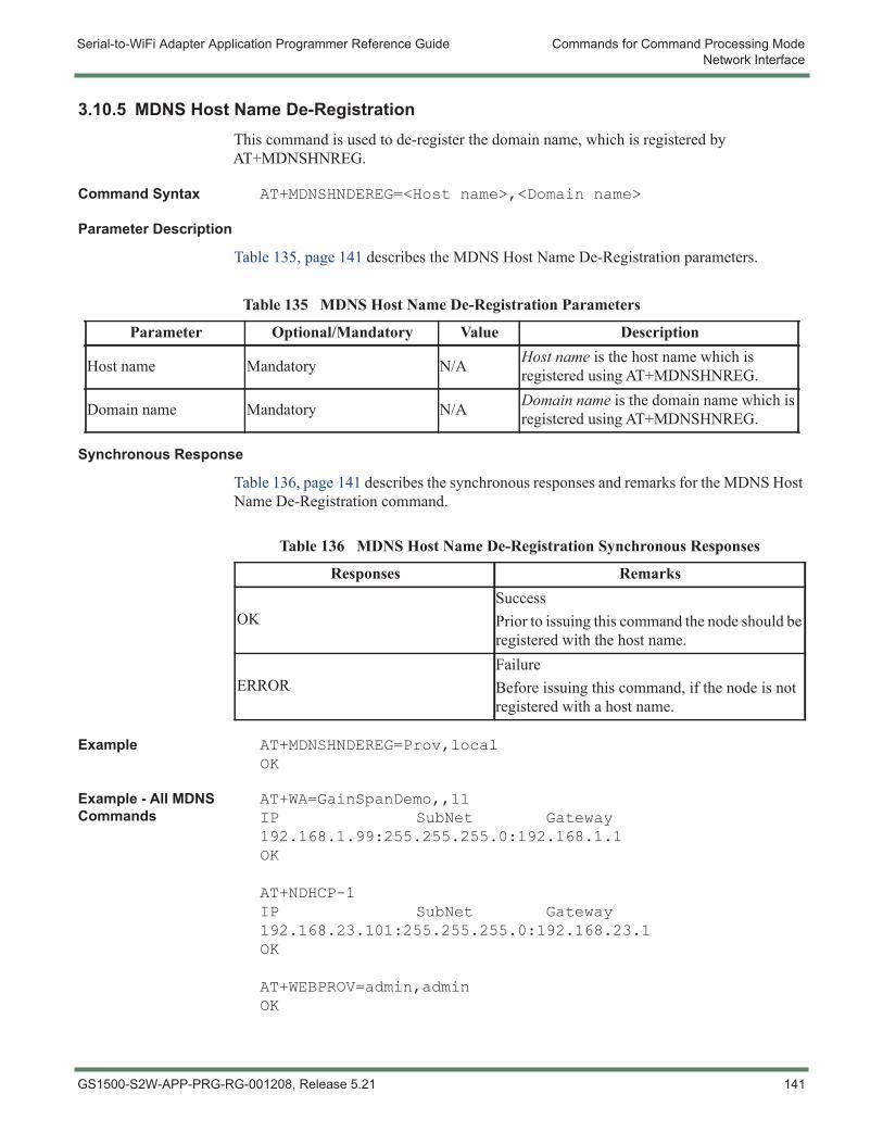
Serial-to-WiFi Adapter Application Programmer Reference Guide Commands for Command Processing ModeNetwork Interface
3.10.5 MDNS Host Name De-RegistrationThis command is used to de-register the domain name, which is registered by AT+MDNSHNREG.
Command Syntax AT+MDNSHNDEREG=<Host name>,<Domain name>
Parameter Description
Table 135, page 141 describes the MDNS Host Name De-Registration parameters.
Synchronous Response
Table 136, page 141 describes the synchronous responses and remarks for the MDNS Host Name De-Registration command.
Example AT+MDNSHNDEREG=Prov,localOK
Example - All MDNS Commands
AT+WA=GainSpanDemo,,11IP SubNet Gateway192.168.1.99:255.255.255.0:192.168.1.1OK
AT+NDHCP-1IP SubNet Gateway192.168.23.101:255.255.255.0:192.168.23.1OK
AT+WEBPROV=admin,adminOK
Table 135 MDNS Host Name De-Registration Parameters
Parameter Optional/Mandatory Value Description
Host name Mandatory N/A Host name is the host name which is registered using AT+MDNSHNREG.
Domain name Mandatory N/A Domain name is the domain name which is registered using AT+MDNSHNREG.
Table 136 MDNS Host Name De-Registration Synchronous Responses
Responses Remarks
OKSuccessPrior to issuing this command the node should be registered with the host name.
ERRORFailureBefore issuing this command, if the node is not registered with a host name.
GS1500-S2W-APP-PRG-RG-001208, Release 5.21 141
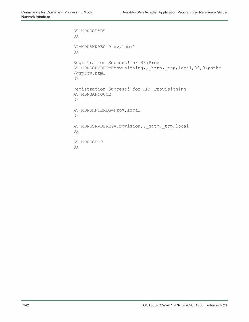
Commands for Command Processing Mode Serial-to-WiFi Adapter Application Programmer Reference GuideNetwork Interface
AT+MDNSSTARTOK
AT+MDNSHNREG=Prov,localOK
Registration Success!for RR:ProvAT+MDNSSRVREG=Provisioning,,_http,_tcp,local,80,0,path=/gsprov.htmlOK
Registration Success!!for RR: ProvisioningAT+MDNSANNOUCEOK
AT+MDNSHNDEREG=Prov,localOK
AT+MDNSSRVDEREG=Provision,,_http,_tcp,localOK
AT+MDNSSTOPOK
142 GS1500-S2W-APP-PRG-RG-001208, Release 5.21
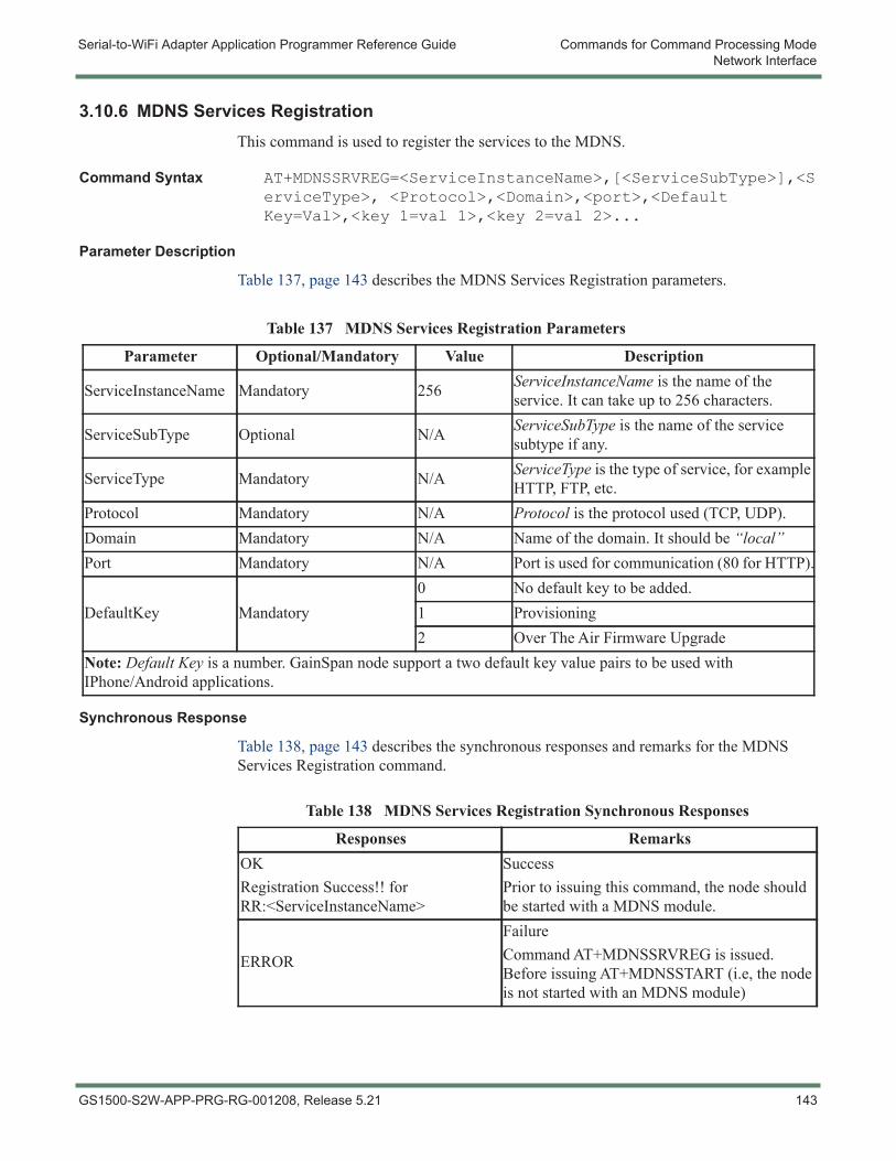
Serial-to-WiFi Adapter Application Programmer Reference Guide Commands for Command Processing ModeNetwork Interface
3.10.6 MDNS Services RegistrationThis command is used to register the services to the MDNS.
Command Syntax AT+MDNSSRVREG=<ServiceInstanceName>,[<ServiceSubType>],<ServiceType>, <Protocol>,<Domain>,<port>,<Default Key=Val>,<key 1=val 1>,<key 2=val 2>...
Parameter Description
Table 137, page 143 describes the MDNS Services Registration parameters.
Synchronous Response
Table 138, page 143 describes the synchronous responses and remarks for the MDNS Services Registration command.
Table 137 MDNS Services Registration Parameters
Parameter Optional/Mandatory Value Description
ServiceInstanceName Mandatory 256 ServiceInstanceName is the name of the service. It can take up to 256 characters.
ServiceSubType Optional N/A ServiceSubType is the name of the service subtype if any.
ServiceType Mandatory N/A ServiceType is the type of service, for example HTTP, FTP, etc.
Protocol Mandatory N/A Protocol is the protocol used (TCP, UDP).Domain Mandatory N/A Name of the domain. It should be “local”Port Mandatory N/A Port is used for communication (80 for HTTP).
DefaultKey Mandatory0 No default key to be added.1 Provisioning2 Over The Air Firmware Upgrade
Note: Default Key is a number. GainSpan node support a two default key value pairs to be used with IPhone/Android applications.
Table 138 MDNS Services Registration Synchronous Responses
Responses RemarksOKRegistration Success!! for RR:<ServiceInstanceName>
SuccessPrior to issuing this command, the node should be started with a MDNS module.
ERROR
FailureCommand AT+MDNSSRVREG is issued. Before issuing AT+MDNSSTART (i.e, the node is not started with an MDNS module)
GS1500-S2W-APP-PRG-RG-001208, Release 5.21 143
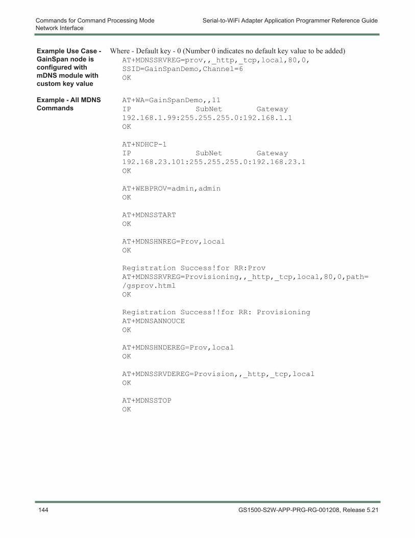
Commands for Command Processing Mode Serial-to-WiFi Adapter Application Programmer Reference GuideNetwork Interface
Example Use Case - GainSpan node is configured with mDNS module with custom key value
Where - Default key - 0 (Number 0 indicates no default key value to be added)AT+MDNSSRVREG=prov,,_http,_tcp,local,80,0,SSID=GainSpanDemo,Channel=6OK
Example - All MDNS Commands
AT+WA=GainSpanDemo,,11IP SubNet Gateway192.168.1.99:255.255.255.0:192.168.1.1OK
AT+NDHCP-1IP SubNet Gateway192.168.23.101:255.255.255.0:192.168.23.1OK
AT+WEBPROV=admin,adminOK
AT+MDNSSTARTOK
AT+MDNSHNREG=Prov,localOK
Registration Success!for RR:ProvAT+MDNSSRVREG=Provisioning,,_http,_tcp,local,80,0,path=/gsprov.htmlOK
Registration Success!!for RR: ProvisioningAT+MDNSANNOUCEOK
AT+MDNSHNDEREG=Prov,localOK
AT+MDNSSRVDEREG=Provision,,_http,_tcp,localOK
AT+MDNSSTOPOK
144 GS1500-S2W-APP-PRG-RG-001208, Release 5.21
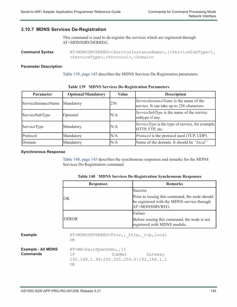
Serial-to-WiFi Adapter Application Programmer Reference Guide Commands for Command Processing ModeNetwork Interface
3.10.7 MDNS Services De-RegistrationThis command is used to de-register the services which are registered through AT+MDNSSRVDERREG.
Command Syntax AT+MDNSSRVDEREG=<ServiceInstanceName>,[<ServiceSubType>],<ServiceType>,<Protocol>,<Domain>
Parameter Description
Table 139, page 145 describes the MDNS Services De-Registration parameters.
Synchronous Response
Table 140, page 145 describes the synchronous responses and remarks for the MDNS Services De-Registration command.
Example AT+MDNSSRVDEREG=Prov,,_http,_tcp,localOK
Example - All MDNS Commands
AT+WA=GainSpanDemo,,11IP SubNet Gateway192.168.1.99:255.255.255.0:192.168.1.1OK
Table 139 MDNS Services De-Registration Parameters
Parameter Optional/Mandatory Value Description
ServiceInstanceName Mandatory 256 ServiceInstanceName is the name of the service. It can take up to 256 characters.
ServiceSubType Optional N/A ServiceSubType is the name of the service subtype if any.
ServiceType Mandatory N/A ServiceType is the type of service, for example HTTP, FTP, etc.
Protocol Mandatory N/A Protocol is the protocol used (TCP, UDP).Domain Mandatory N/A Name of the domain. It should be “local”
Table 140 MDNS Services De-Registration Synchronous Responses
Responses Remarks
OK
SuccessPrior to issuing this command, the node should be registered with the MDNS service through AT+MDNSSRVREG.
ERRORFailureBefore issuing this command, the node is not registered with MDNS module.
GS1500-S2W-APP-PRG-RG-001208, Release 5.21 145
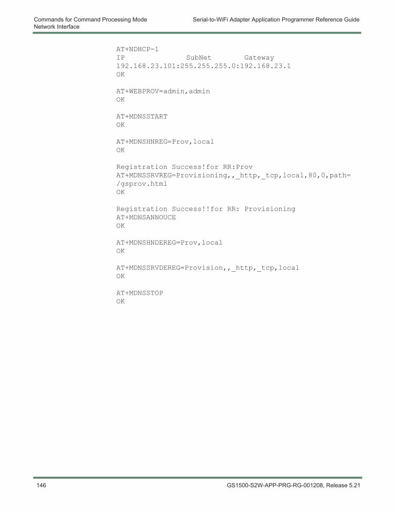
Commands for Command Processing Mode Serial-to-WiFi Adapter Application Programmer Reference GuideNetwork Interface
AT+NDHCP-1IP SubNet Gateway192.168.23.101:255.255.255.0:192.168.23.1OK
AT+WEBPROV=admin,adminOK
AT+MDNSSTARTOK
AT+MDNSHNREG=Prov,localOK
Registration Success!for RR:ProvAT+MDNSSRVREG=Provisioning,,_http,_tcp,local,80,0,path=/gsprov.htmlOK
Registration Success!!for RR: ProvisioningAT+MDNSANNOUCEOK
AT+MDNSHNDEREG=Prov,localOK
AT+MDNSSRVDEREG=Provision,,_http,_tcp,localOK
AT+MDNSSTOPOK
146 GS1500-S2W-APP-PRG-RG-001208, Release 5.21
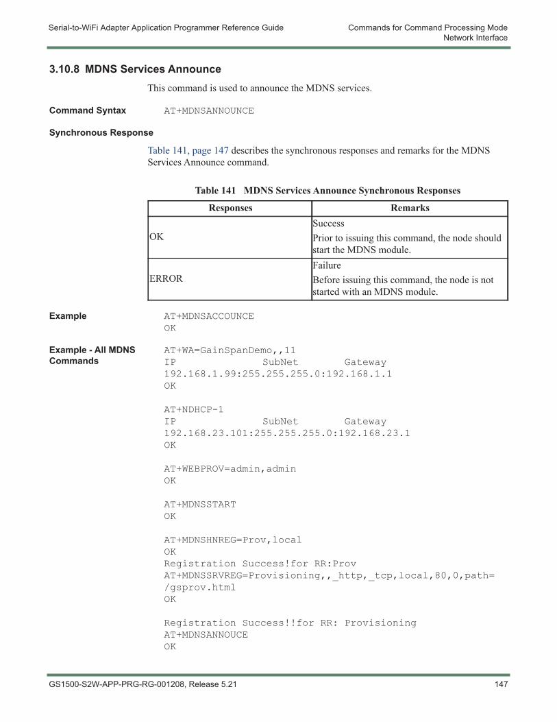
Serial-to-WiFi Adapter Application Programmer Reference Guide Commands for Command Processing ModeNetwork Interface
3.10.8 MDNS Services AnnounceThis command is used to announce the MDNS services.
Command Syntax AT+MDNSANNOUNCE
Synchronous Response
Table 141, page 147 describes the synchronous responses and remarks for the MDNS Services Announce command.
Example AT+MDNSACCOUNCEOK
Example - All MDNS Commands
AT+WA=GainSpanDemo,,11IP SubNet Gateway192.168.1.99:255.255.255.0:192.168.1.1OK
AT+NDHCP-1IP SubNet Gateway192.168.23.101:255.255.255.0:192.168.23.1OK
AT+WEBPROV=admin,adminOK
AT+MDNSSTARTOK
AT+MDNSHNREG=Prov,localOKRegistration Success!for RR:ProvAT+MDNSSRVREG=Provisioning,,_http,_tcp,local,80,0,path=/gsprov.htmlOK
Registration Success!!for RR: ProvisioningAT+MDNSANNOUCEOK
Table 141 MDNS Services Announce Synchronous Responses
Responses Remarks
OKSuccessPrior to issuing this command, the node should start the MDNS module.
ERRORFailureBefore issuing this command, the node is not started with an MDNS module.
GS1500-S2W-APP-PRG-RG-001208, Release 5.21 147
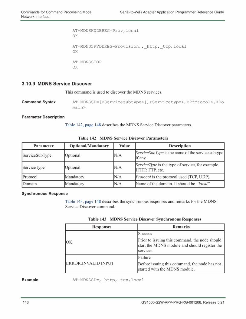
Commands for Command Processing Mode Serial-to-WiFi Adapter Application Programmer Reference GuideNetwork Interface
AT+MDNSHNDEREG=Prov,localOK
AT+MDNSSRVDEREG=Provision,,_http,_tcp,localOK
AT+MDNSSTOPOK
3.10.9 MDNS Service DiscoverThis command is used to discover the MDNS services.
Command Syntax AT+MDNSSD=[<Servicesubtype>],<Servicetype>,<Protocol>,<Domain>
Parameter Description
Table 142, page 148 describes the MDNS Service Discover parameters.
Synchronous Response
Table 143, page 148 describes the synchronous responses and remarks for the MDNS Service Discover command.
Example AT+MDNSSD=,_http,_tcp,local
Table 142 MDNS Service Discover Parameters
Parameter Optional/Mandatory Value Description
ServiceSubType Optional N/A ServiceSubType is the name of the service subtype if any.
ServiceType Optional N/A ServiceType is the type of service, for example HTTP, FTP, etc.
Protocol Mandatory N/A Protocol is the protocol used (TCP, UDP).Domain Mandatory N/A Name of the domain. It should be “local”
Table 143 MDNS Service Discover Synchronous Responses
Responses Remarks
OK
SuccessPrior to issuing this command, the node should start the MDNS module and should register the services.
ERROR:INVALID INPUTFailureBefore issuing this command, the node has not started with the MDNS module.
148 GS1500-S2W-APP-PRG-RG-001208, Release 5.21
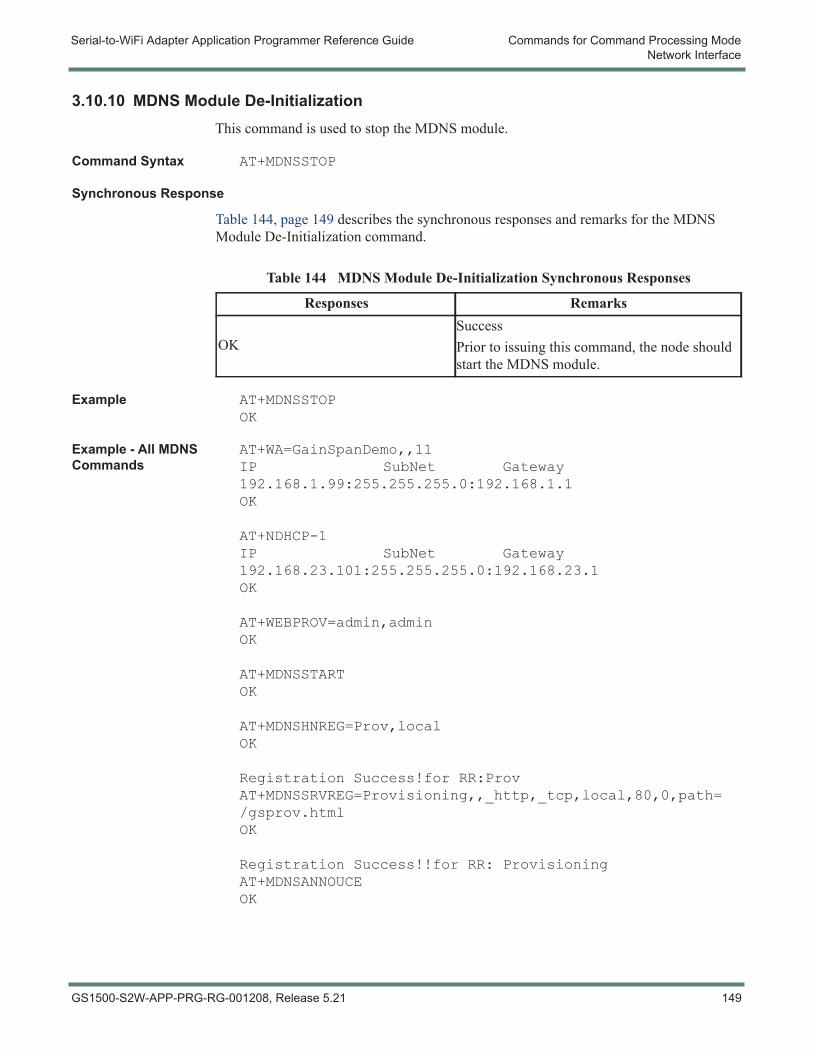
Serial-to-WiFi Adapter Application Programmer Reference Guide Commands for Command Processing ModeNetwork Interface
3.10.10 MDNS Module De-InitializationThis command is used to stop the MDNS module.
Command Syntax AT+MDNSSTOP
Synchronous Response
Table 144, page 149 describes the synchronous responses and remarks for the MDNS Module De-Initialization command.
Example AT+MDNSSTOPOK
Example - All MDNS Commands
AT+WA=GainSpanDemo,,11IP SubNet Gateway192.168.1.99:255.255.255.0:192.168.1.1OK
AT+NDHCP-1IP SubNet Gateway192.168.23.101:255.255.255.0:192.168.23.1OK
AT+WEBPROV=admin,adminOK
AT+MDNSSTARTOK
AT+MDNSHNREG=Prov,localOK
Registration Success!for RR:ProvAT+MDNSSRVREG=Provisioning,,_http,_tcp,local,80,0,path=/gsprov.htmlOK
Registration Success!!for RR: ProvisioningAT+MDNSANNOUCEOK
Table 144 MDNS Module De-Initialization Synchronous Responses
Responses Remarks
OKSuccessPrior to issuing this command, the node should start the MDNS module.
GS1500-S2W-APP-PRG-RG-001208, Release 5.21 149
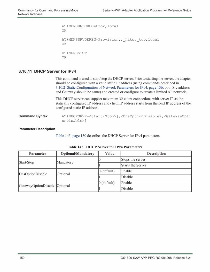
Commands for Command Processing Mode Serial-to-WiFi Adapter Application Programmer Reference GuideNetwork Interface
AT+MDNSHNDEREG=Prov,localOK
AT+MDNSSRVDEREG=Provision,,_http,_tcp,localOK
AT+MDNSSTOPOK
3.10.11 DHCP Server for IPv4This command is used to start/stop the DHCP server. Prior to starting the server, the adapter should be configured with a valid static IP address (using commands described in 3.10.2 Static Configuration of Network Parameters for IPv4, page 136, both Src address and Gateway should be same) and created or configure to create a limited AP network.
This DHCP server can support maximum 32 client connections with server IP as the statically configured IP address and client IP address starts from the next IP address of the configured static IP address.
Command Syntax AT+DHCPSRVR=<Start/Stop>[,<DnsOptionDisable>,<GatewayOptionDisable>]
Parameter Description
Table 145, page 150 describes the DHCP Server for IPv4 parameters.
Table 145 DHCP Server for IPv4 Parameters
Parameter Optional/Mandatory Value Description
Start/Stop Mandatory0 Stops the server1 Starts the Server
DnsOptionDisable Optional0 (default) Enable1 Disable
GatewayOptionDisable Optional0 (default) Enable1 Disable
150 GS1500-S2W-APP-PRG-RG-001208, Release 5.21
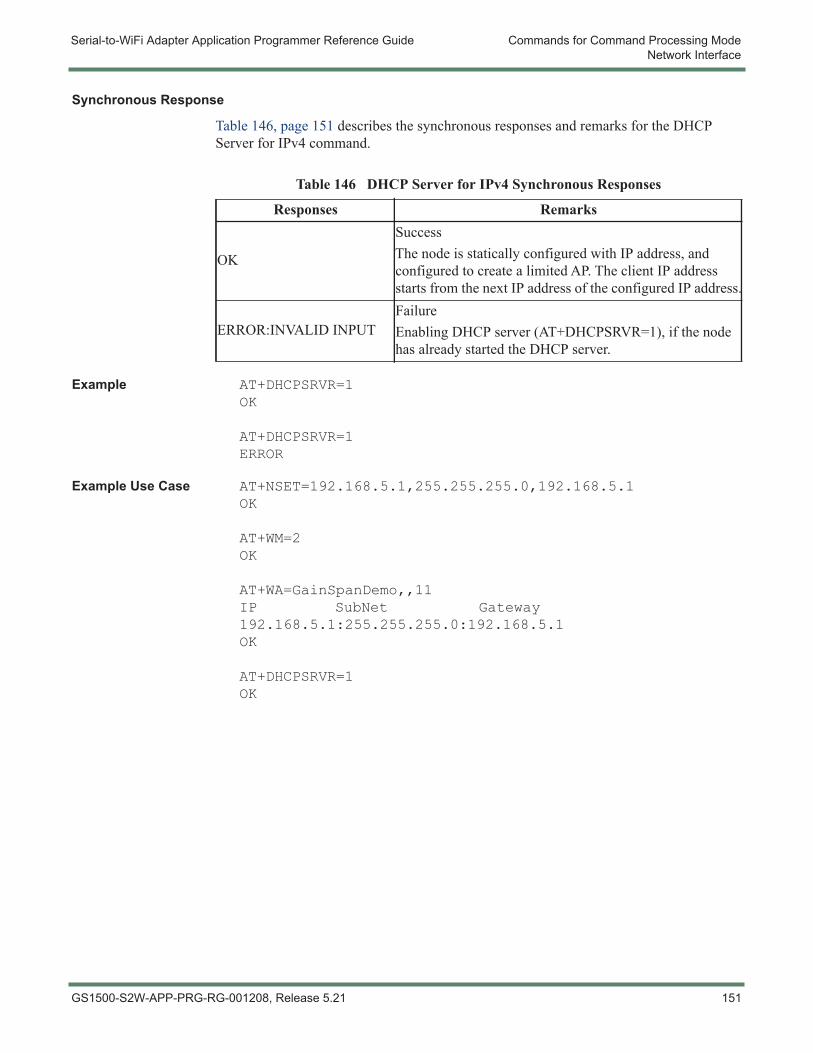
Serial-to-WiFi Adapter Application Programmer Reference Guide Commands for Command Processing ModeNetwork Interface
Synchronous Response
Table 146, page 151 describes the synchronous responses and remarks for the DHCP Server for IPv4 command.
Example AT+DHCPSRVR=1OK
AT+DHCPSRVR=1ERROR
Example Use Case AT+NSET=192.168.5.1,255.255.255.0,192.168.5.1OK
AT+WM=2OK
AT+WA=GainSpanDemo,,11IP SubNet Gateway192.168.5.1:255.255.255.0:192.168.5.1OK
AT+DHCPSRVR=1OK
Table 146 DHCP Server for IPv4 Synchronous Responses
Responses Remarks
OK
SuccessThe node is statically configured with IP address, and configured to create a limited AP. The client IP address starts from the next IP address of the configured IP address.
ERROR:INVALID INPUTFailureEnabling DHCP server (AT+DHCPSRVR=1), if the node has already started the DHCP server.
GS1500-S2W-APP-PRG-RG-001208, Release 5.21 151

Commands for Command Processing Mode Serial-to-WiFi Adapter Application Programmer Reference GuideNetwork Interface
152 GS1500-S2W-APP-PRG-RG-001208, Release 5.21
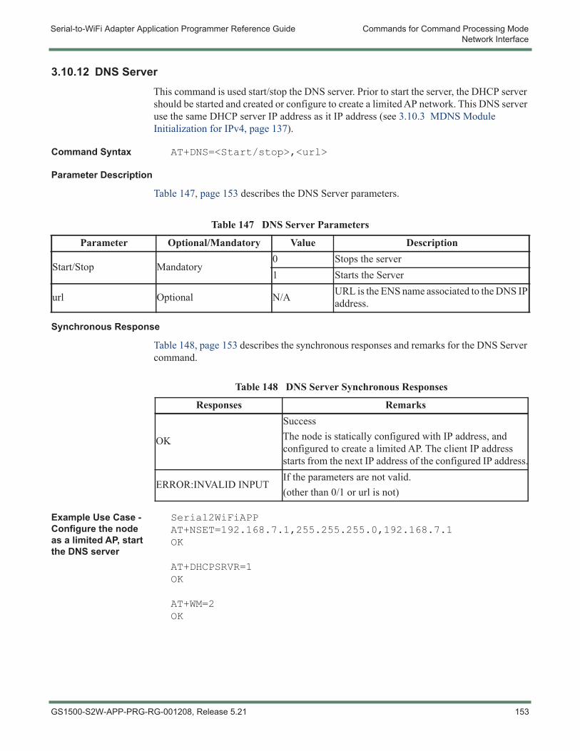
Serial-to-WiFi Adapter Application Programmer Reference Guide Commands for Command Processing ModeNetwork Interface
3.10.12 DNS ServerThis command is used start/stop the DNS server. Prior to start the server, the DHCP server should be started and created or configure to create a limited AP network. This DNS server use the same DHCP server IP address as it IP address (see 3.10.3 MDNS Module Initialization for IPv4, page 137).
Command Syntax AT+DNS=<Start/stop>,<url>
Parameter Description
Table 147, page 153 describes the DNS Server parameters.
Synchronous Response
Table 148, page 153 describes the synchronous responses and remarks for the DNS Server command.
Example Use Case - Configure the node as a limited AP, start the DNS server
Serial2WiFiAPPAT+NSET=192.168.7.1,255.255.255.0,192.168.7.1OK
AT+DHCPSRVR=1OK
AT+WM=2OK
Table 147 DNS Server Parameters
Parameter Optional/Mandatory Value Description
Start/Stop Mandatory0 Stops the server1 Starts the Server
url Optional N/A URL is the ENS name associated to the DNS IP address.
Table 148 DNS Server Synchronous Responses
Responses Remarks
OK
SuccessThe node is statically configured with IP address, and configured to create a limited AP. The client IP address starts from the next IP address of the configured IP address.
ERROR:INVALID INPUTIf the parameters are not valid.(other than 0/1 or url is not)
GS1500-S2W-APP-PRG-RG-001208, Release 5.21 153
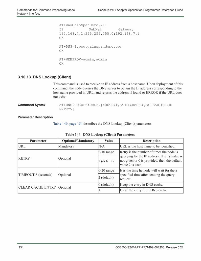
Commands for Command Processing Mode Serial-to-WiFi Adapter Application Programmer Reference GuideNetwork Interface
AT+WA=GainSpanDemo,,11IP SubNet Gateway192.168.7.1:255.255.255.0:192.168.7.1OK
AT+DNS=1,www.gainspandemo.comOK
AT+WEBPROV=admin,adminOK
3.10.13 DNS Lookup (Client)This command is used to receive an IP address from a host name. Upon deployment of this command, the node queries the DNS server to obtain the IP address corresponding to the host name provided in URL, and returns the address if found or ERROR if the URL does not exist.
Command Syntax AT+DNSLOOKUP=<URL>,[<RETRY>,<TIMEOUT-S>,<CLEAR CACHE ENTRY>]
Parameter Description
Table 149, page 154 describes the DNS Lookup (Client) parameters.
Table 149 DNS Lookup (Client) Parameters
Parameter Optional/Mandatory Value DescriptionURL Mandatory N/A URL is the host name to be identified.
RETRY Optional
0-10 range Retry is the number of times the node is querying for the IP address. If retry value is not given or 0 is provided, then the default value 2 is used.
2 (default)
TIMEOUT-S (seconds) Optional0-20 range It is the time he node will wait for the a
specified time after sending the query request.2 (default)
CLEAR CACHE ENTRY Optional0 (default) Keep the entry in DNS cache.1 Clear the entry form DNS cache.
154 GS1500-S2W-APP-PRG-RG-001208, Release 5.21
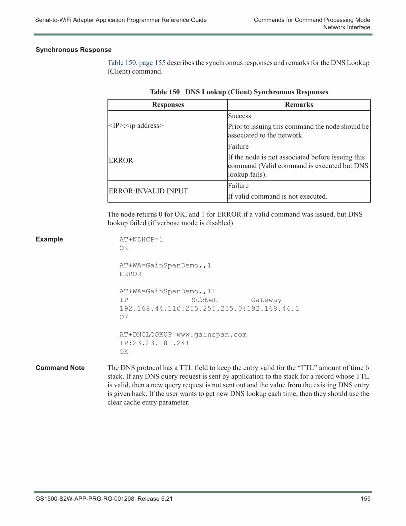
Serial-to-WiFi Adapter Application Programmer Reference Guide Commands for Command Processing ModeNetwork Interface
Synchronous Response
Table 150, page 155 describes the synchronous responses and remarks for the DNS Lookup (Client) command.
The node returns 0 for OK, and 1 for ERROR if a valid command was issued, but DNS lookup failed (if verbose mode is disabled).
Example AT+NDHCP=1OK
AT+WA=GainSpanDemo,,1ERROR
AT+WA=GainSpanDemo,,11IP SubNet Gateway192.168.44.110:255.255.255.0:192.168.44.1OK
AT+DNCLOOKUP=www.gainspan.comIP:23.23.181.241OK
Command Note The DNS protocol has a TTL field to keep the entry valid for the “TTL” amount of time b stack. If any DNS query request is sent by application to the stack for a record whose TTL is valid, then a new query request is not sent out and the value from the existing DNS entry is given back. If the user wants to get new DNS lookup each time, then they should use the clear cache entry parameter.
Table 150 DNS Lookup (Client) Synchronous Responses
Responses Remarks
<IP>:<ip address>SuccessPrior to issuing this command the node should be associated to the network.
ERROR
FailureIf the node is not associated before issuing this command (Valid command is executed but DNS lookup fails).
ERROR:INVALID INPUTFailureIf valid command is not executed.
GS1500-S2W-APP-PRG-RG-001208, Release 5.21 155
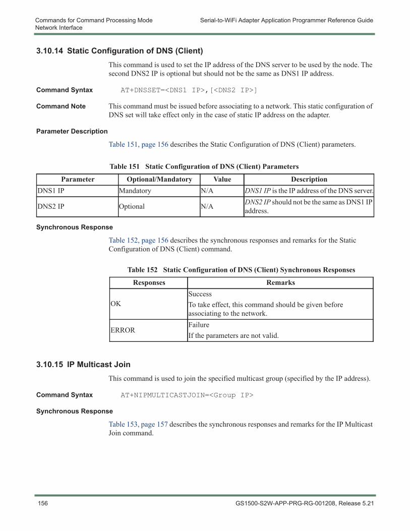
Commands for Command Processing Mode Serial-to-WiFi Adapter Application Programmer Reference GuideNetwork Interface
3.10.14 Static Configuration of DNS (Client)This command is used to set the IP address of the DNS server to be used by the node. The second DNS2 IP is optional but should not be the same as DNS1 IP address.
Command Syntax AT+DNSSET=<DNS1 IP>,[<DNS2 IP>]
Command Note This command must be issued before associating to a network. This static configuration of DNS set will take effect only in the case of static IP address on the adapter.
Parameter Description
Table 151, page 156 describes the Static Configuration of DNS (Client) parameters.
Synchronous Response
Table 152, page 156 describes the synchronous responses and remarks for the Static Configuration of DNS (Client) command.
3.10.15 IP Multicast JoinThis command is used to join the specified multicast group (specified by the IP address).
Command Syntax AT+NIPMULTICASTJOIN=<Group IP>
Synchronous Response
Table 153, page 157 describes the synchronous responses and remarks for the IP Multicast Join command.
Table 151 Static Configuration of DNS (Client) Parameters
Parameter Optional/Mandatory Value DescriptionDNS1 IP Mandatory N/A DNS1 IP is the IP address of the DNS server.
DNS2 IP Optional N/A DNS2 IP should not be the same as DNS1 IP address.
Table 152 Static Configuration of DNS (Client) Synchronous Responses
Responses Remarks
OKSuccessTo take effect, this command should be given before associating to the network.
ERRORFailureIf the parameters are not valid.
156 GS1500-S2W-APP-PRG-RG-001208, Release 5.21
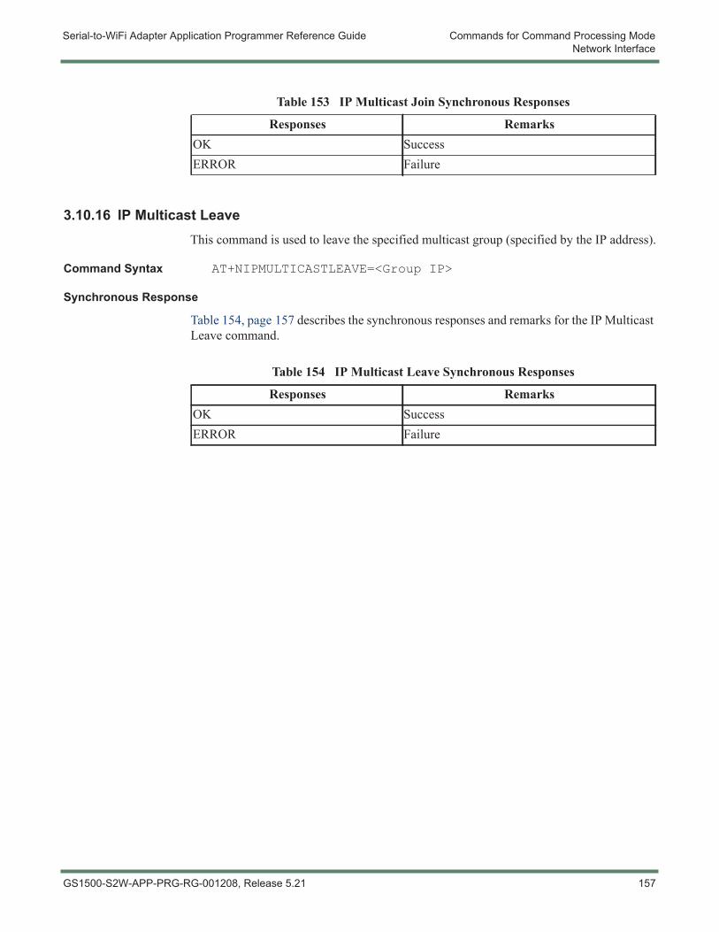
Serial-to-WiFi Adapter Application Programmer Reference Guide Commands for Command Processing ModeNetwork Interface
3.10.16 IP Multicast LeaveThis command is used to leave the specified multicast group (specified by the IP address).
Command Syntax AT+NIPMULTICASTLEAVE=<Group IP>
Synchronous Response
Table 154, page 157 describes the synchronous responses and remarks for the IP Multicast Leave command.
Table 153 IP Multicast Join Synchronous Responses
Responses RemarksOK SuccessERROR Failure
Table 154 IP Multicast Leave Synchronous Responses
Responses RemarksOK SuccessERROR Failure
GS1500-S2W-APP-PRG-RG-001208, Release 5.21 157

Commands for Command Processing Mode Serial-to-WiFi Adapter Application Programmer Reference GuideNetwork Interface
Command Note - For GS1500M
If a device is operating in P2P mode as a client or GO, then this command can be used to store the P2P context.
158 GS1500-S2W-APP-PRG-RG-001208, Release 5.21
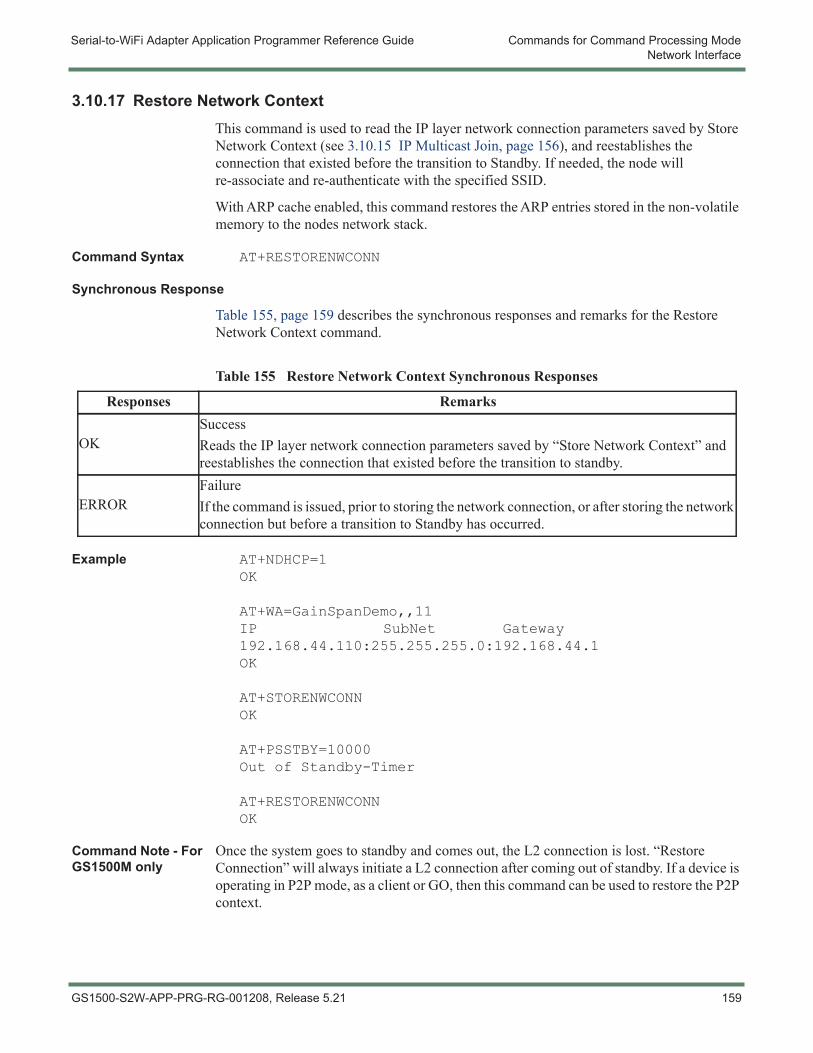
Serial-to-WiFi Adapter Application Programmer Reference Guide Commands for Command Processing ModeNetwork Interface
3.10.17 Restore Network ContextThis command is used to read the IP layer network connection parameters saved by Store Network Context (see 3.10.15 IP Multicast Join, page 156), and reestablishes the connection that existed before the transition to Standby. If needed, the node will re-associate and re-authenticate with the specified SSID.
With ARP cache enabled, this command restores the ARP entries stored in the non-volatile memory to the nodes network stack.
Command Syntax AT+RESTORENWCONN
Synchronous Response
Table 155, page 159 describes the synchronous responses and remarks for the Restore Network Context command.
Example AT+NDHCP=1OK
AT+WA=GainSpanDemo,,11IP SubNet Gateway192.168.44.110:255.255.255.0:192.168.44.1OK
AT+STORENWCONNOK
AT+PSSTBY=10000Out of Standby-Timer
AT+RESTORENWCONNOK
Command Note - For GS1500M only
Once the system goes to standby and comes out, the L2 connection is lost. “Restore Connection” will always initiate a L2 connection after coming out of standby. If a device is operating in P2P mode, as a client or GO, then this command can be used to restore the P2P context.
Table 155 Restore Network Context Synchronous Responses
Responses Remarks
OKSuccessReads the IP layer network connection parameters saved by “Store Network Context” and reestablishes the connection that existed before the transition to standby.
ERRORFailureIf the command is issued, prior to storing the network connection, or after storing the network connection but before a transition to Standby has occurred.
GS1500-S2W-APP-PRG-RG-001208, Release 5.21 159
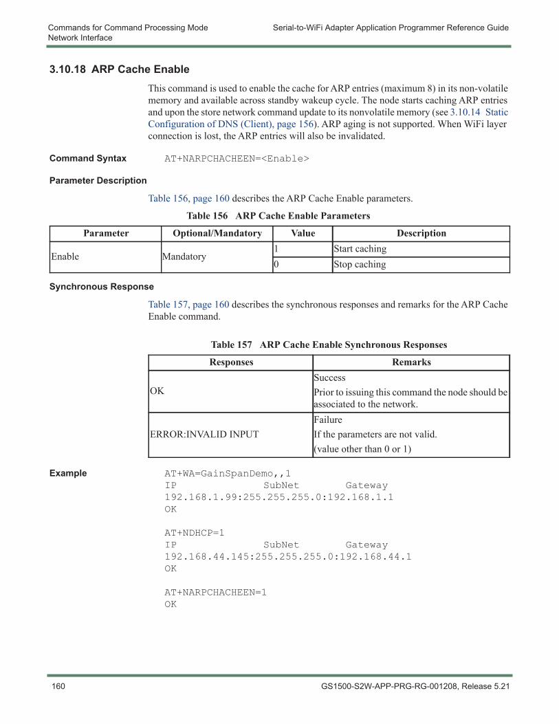
Commands for Command Processing Mode Serial-to-WiFi Adapter Application Programmer Reference GuideNetwork Interface
3.10.18 ARP Cache EnableThis command is used to enable the cache for ARP entries (maximum 8) in its non-volatile memory and available across standby wakeup cycle. The node starts caching ARP entries and upon the store network command update to its nonvolatile memory (see 3.10.14 Static Configuration of DNS (Client), page 156). ARP aging is not supported. When WiFi layer connection is lost, the ARP entries will also be invalidated.
Command Syntax AT+NARPCHACHEEN=<Enable>
Parameter Description
Table 156, page 160 describes the ARP Cache Enable parameters.
Synchronous Response
Table 157, page 160 describes the synchronous responses and remarks for the ARP Cache Enable command.
Example AT+WA=GainSpanDemo,,1IP SubNet Gateway192.168.1.99:255.255.255.0:192.168.1.1OK
AT+NDHCP=1IP SubNet Gateway192.168.44.145:255.255.255.0:192.168.44.1OK
AT+NARPCHACHEEN=1OK
Table 156 ARP Cache Enable Parameters
Parameter Optional/Mandatory Value Description
Enable Mandatory1 Start caching0 Stop caching
Table 157 ARP Cache Enable Synchronous Responses
Responses Remarks
OKSuccessPrior to issuing this command the node should be associated to the network.
ERROR:INVALID INPUTFailureIf the parameters are not valid.(value other than 0 or 1)
160 GS1500-S2W-APP-PRG-RG-001208, Release 5.21
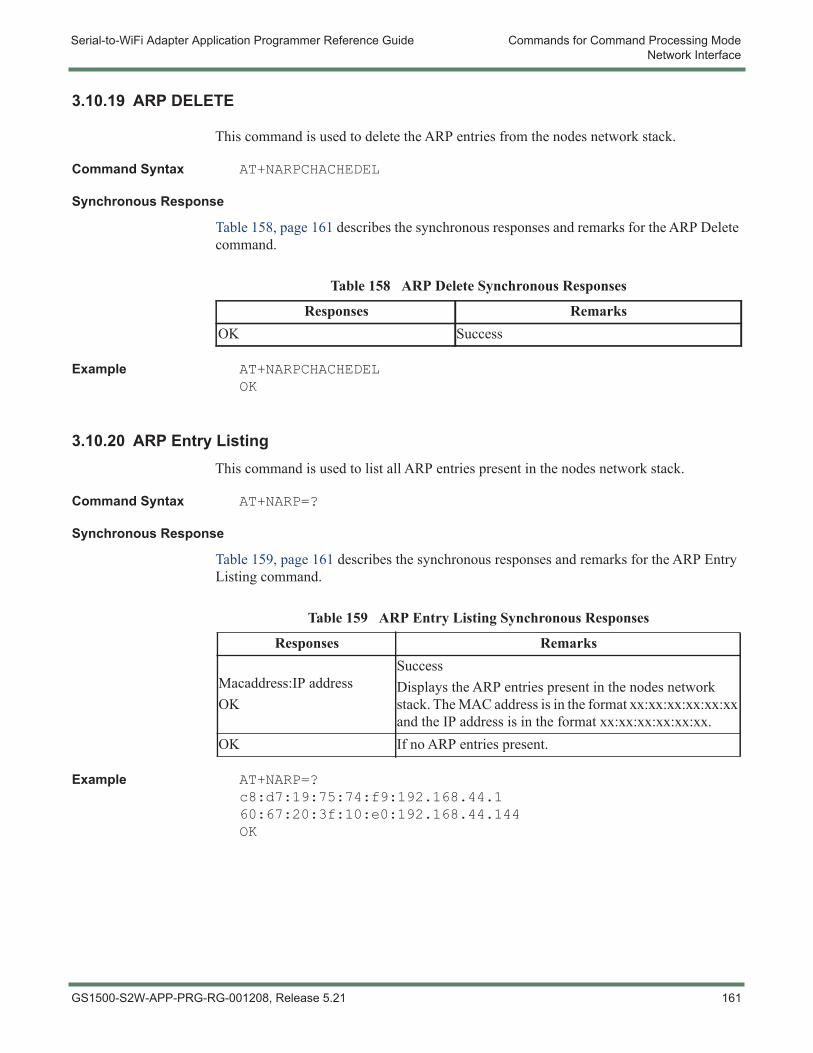
Serial-to-WiFi Adapter Application Programmer Reference Guide Commands for Command Processing ModeNetwork Interface
3.10.19 ARP DELETE
This command is used to delete the ARP entries from the nodes network stack.
Command Syntax AT+NARPCHACHEDEL
Synchronous Response
Table 158, page 161 describes the synchronous responses and remarks for the ARP Delete command.
Example AT+NARPCHACHEDELOK
3.10.20 ARP Entry ListingThis command is used to list all ARP entries present in the nodes network stack.
Command Syntax AT+NARP=?
Synchronous Response
Table 159, page 161 describes the synchronous responses and remarks for the ARP Entry Listing command.
Example AT+NARP=?c8:d7:19:75:74:f9:192.168.44.160:67:20:3f:10:e0:192.168.44.144OK
Table 158 ARP Delete Synchronous Responses
Responses RemarksOK Success
Table 159 ARP Entry Listing Synchronous Responses
Responses Remarks
Macaddress:IP address OK
SuccessDisplays the ARP entries present in the nodes network stack. The MAC address is in the format xx:xx:xx:xx:xx:xx and the IP address is in the format xx:xx:xx:xx:xx:xx.
OK If no ARP entries present.
GS1500-S2W-APP-PRG-RG-001208, Release 5.21 161
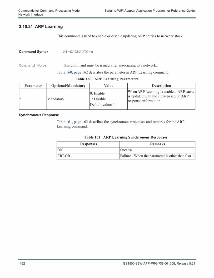
Commands for Command Processing Mode Serial-to-WiFi Adapter Application Programmer Reference GuideNetwork Interface
3.10.21 ARP Learning
This command is used to enable or disable updating ARP entries to network stack.
Command Syntax AT+NARPAUTO=n
Command Note This command must be issued after associating to a network.
Table 160, page 162 describes the parameter in ARP Learning command.
Synchronous Response
Table 161, page 162 describes the synchronous responses and remarks for the ARP Learning command.
Table 160 ARP Learning Parameters
Parameter Optional/Mandatory Value Description
n Mandatory0: Enable1: DisableDefault value: 1
When ARP Learning is enabled, ARP cache is updated with the entry based on ARP response information.
Table 161 ARP Learning Synchronous Responses
Responses RemarksOK SuccessERROR Failure - When the parameter is other than 0 or 1.
162 GS1500-S2W-APP-PRG-RG-001208, Release 5.21
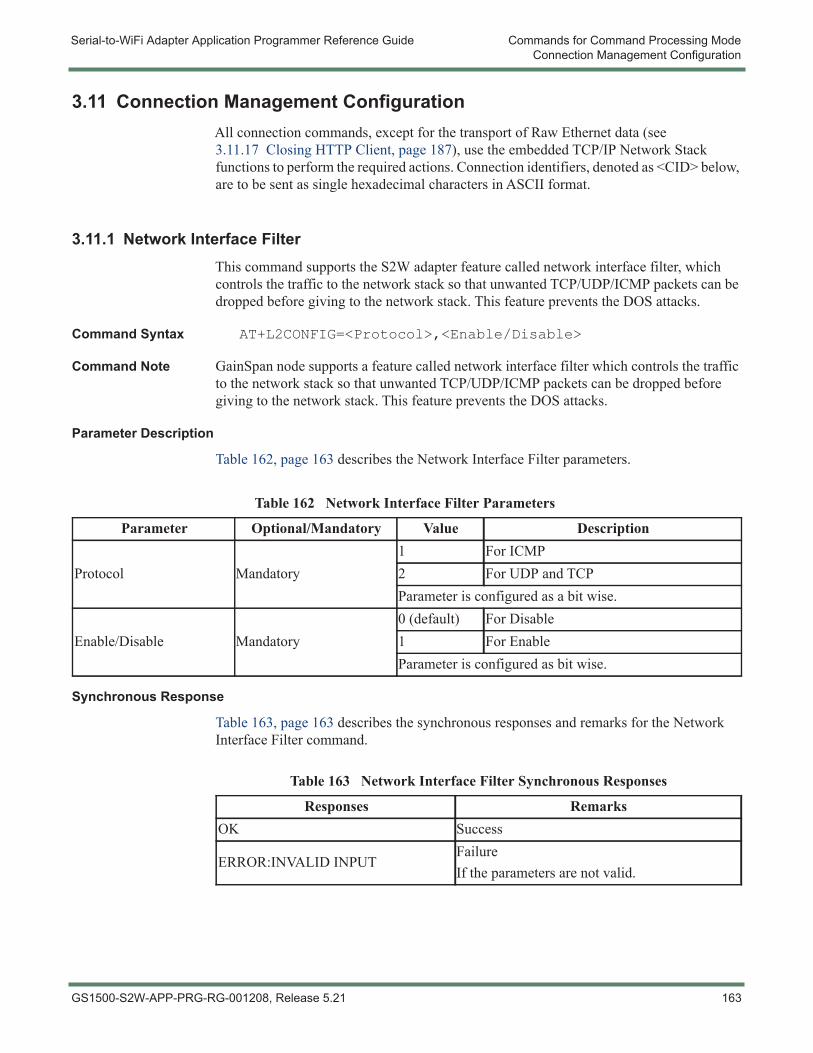
Serial-to-WiFi Adapter Application Programmer Reference Guide Commands for Command Processing ModeConnection Management Configuration
3.11 Connection Management ConfigurationAll connection commands, except for the transport of Raw Ethernet data (see 3.11.17 Closing HTTP Client, page 187), use the embedded TCP/IP Network Stack functions to perform the required actions. Connection identifiers, denoted as <CID> below, are to be sent as single hexadecimal characters in ASCII format.
3.11.1 Network Interface FilterThis command supports the S2W adapter feature called network interface filter, which controls the traffic to the network stack so that unwanted TCP/UDP/ICMP packets can be dropped before giving to the network stack. This feature prevents the DOS attacks.
Command Syntax AT+L2CONFIG=<Protocol>,<Enable/Disable>
Command Note GainSpan node supports a feature called network interface filter which controls the traffic to the network stack so that unwanted TCP/UDP/ICMP packets can be dropped before giving to the network stack. This feature prevents the DOS attacks.
Parameter Description
Table 162, page 163 describes the Network Interface Filter parameters.
Synchronous Response
Table 163, page 163 describes the synchronous responses and remarks for the Network Interface Filter command.
Table 162 Network Interface Filter Parameters
Parameter Optional/Mandatory Value Description
Protocol Mandatory1 For ICMP2 For UDP and TCPParameter is configured as a bit wise.
Enable/Disable Mandatory0 (default) For Disable1 For EnableParameter is configured as bit wise.
Table 163 Network Interface Filter Synchronous Responses
Responses RemarksOK Success
ERROR:INVALID INPUTFailureIf the parameters are not valid.
GS1500-S2W-APP-PRG-RG-001208, Release 5.21 163
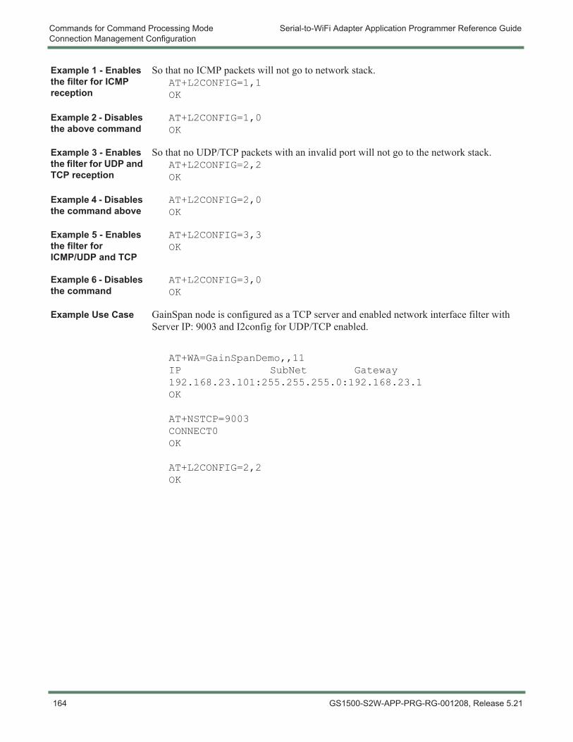
Commands for Command Processing Mode Serial-to-WiFi Adapter Application Programmer Reference GuideConnection Management Configuration
Example 1 - Enables the filter for ICMP reception
So that no ICMP packets will not go to network stack.AT+L2CONFIG=1,1OK
Example 2 - Disables the above command
AT+L2CONFIG=1,0OK
Example 3 - Enables the filter for UDP and TCP reception
So that no UDP/TCP packets with an invalid port will not go to the network stack.AT+L2CONFIG=2,2OK
Example 4 - Disables the command above
AT+L2CONFIG=2,0OK
Example 5 - Enables the filter for ICMP/UDP and TCP
AT+L2CONFIG=3,3OK
Example 6 - Disables the command
AT+L2CONFIG=3,0OK
Example Use Case GainSpan node is configured as a TCP server and enabled network interface filter with Server IP: 9003 and I2config for UDP/TCP enabled.
AT+WA=GainSpanDemo,,11IP SubNet Gateway192.168.23.101:255.255.255.0:192.168.23.1OK
AT+NSTCP=9003CONNECT0OK
AT+L2CONFIG=2,2OK
164 GS1500-S2W-APP-PRG-RG-001208, Release 5.21
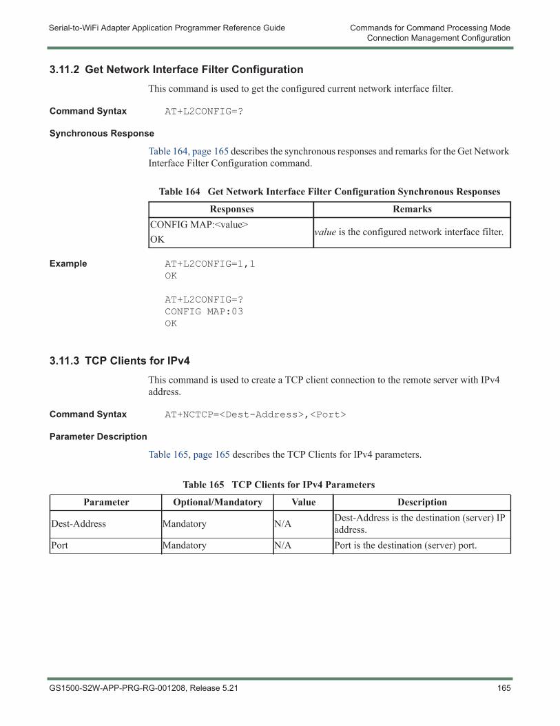
Serial-to-WiFi Adapter Application Programmer Reference Guide Commands for Command Processing ModeConnection Management Configuration
3.11.2 Get Network Interface Filter ConfigurationThis command is used to get the configured current network interface filter.
Command Syntax AT+L2CONFIG=?
Synchronous Response
Table 164, page 165 describes the synchronous responses and remarks for the Get Network Interface Filter Configuration command.
Example AT+L2CONFIG=1,1OK
AT+L2CONFIG=?CONFIG MAP:03OK
3.11.3 TCP Clients for IPv4This command is used to create a TCP client connection to the remote server with IPv4 address.
Command Syntax AT+NCTCP=<Dest-Address>,<Port>
Parameter Description
Table 165, page 165 describes the TCP Clients for IPv4 parameters.
Table 164 Get Network Interface Filter Configuration Synchronous Responses
Responses RemarksCONFIG MAP:<value>OK
value is the configured network interface filter.
Table 165 TCP Clients for IPv4 Parameters
Parameter Optional/Mandatory Value Description
Dest-Address Mandatory N/A Dest-Address is the destination (server) IP address.
Port Mandatory N/A Port is the destination (server) port.
GS1500-S2W-APP-PRG-RG-001208, Release 5.21 165
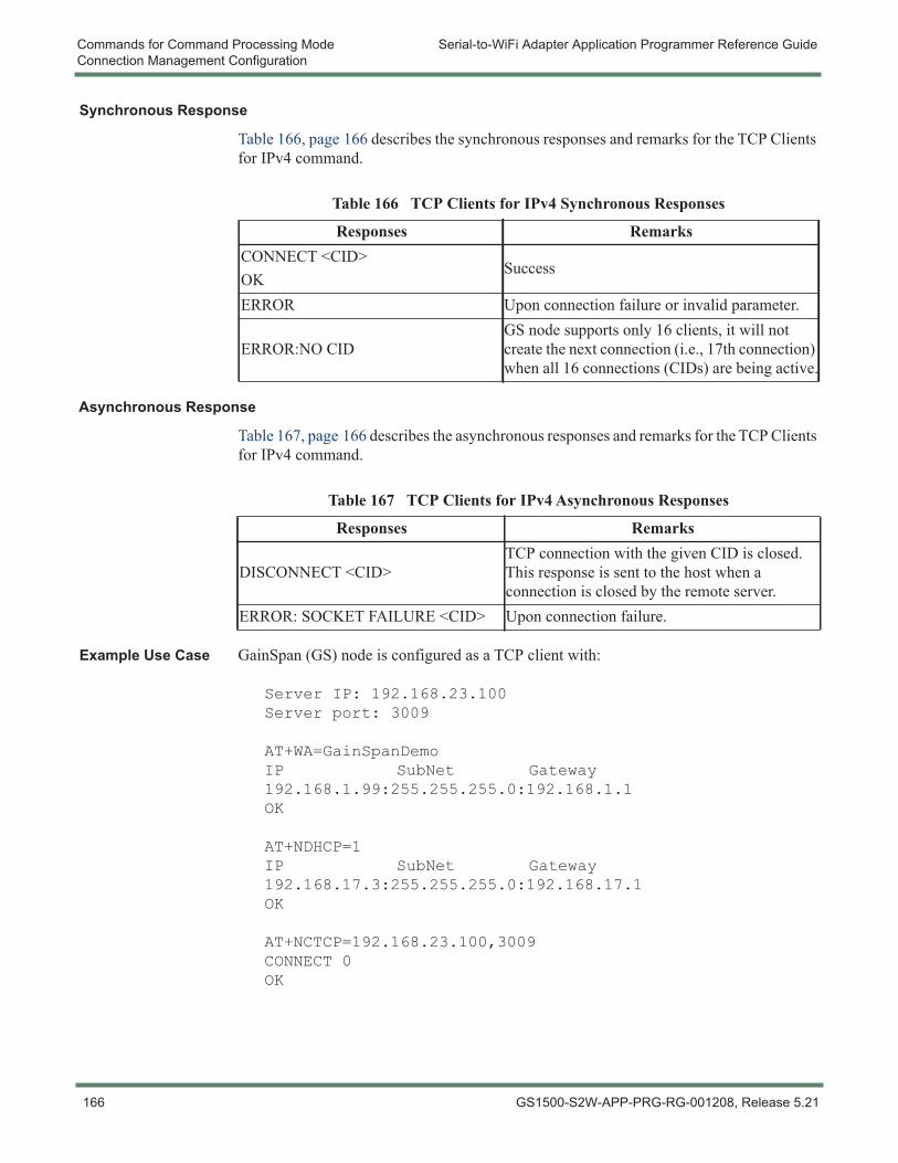
Commands for Command Processing Mode Serial-to-WiFi Adapter Application Programmer Reference GuideConnection Management Configuration
Synchronous Response
Table 166, page 166 describes the synchronous responses and remarks for the TCP Clients for IPv4 command.
Asynchronous Response
Table 167, page 166 describes the asynchronous responses and remarks for the TCP Clients for IPv4 command.
Example Use Case GainSpan (GS) node is configured as a TCP client with:
Server IP: 192.168.23.100Server port: 3009
AT+WA=GainSpanDemoIP SubNet Gateway192.168.1.99:255.255.255.0:192.168.1.1OK
AT+NDHCP=1IP SubNet Gateway192.168.17.3:255.255.255.0:192.168.17.1OK
AT+NCTCP=192.168.23.100,3009CONNECT 0OK
Table 166 TCP Clients for IPv4 Synchronous Responses
Responses RemarksCONNECT <CID>OK
Success
ERROR Upon connection failure or invalid parameter.
ERROR:NO CIDGS node supports only 16 clients, it will not create the next connection (i.e., 17th connection) when all 16 connections (CIDs) are being active.
Table 167 TCP Clients for IPv4 Asynchronous Responses
Responses Remarks
DISCONNECT <CID>TCP connection with the given CID is closed. This response is sent to the host when a connection is closed by the remote server.
ERROR: SOCKET FAILURE <CID> Upon connection failure.
166 GS1500-S2W-APP-PRG-RG-001208, Release 5.21
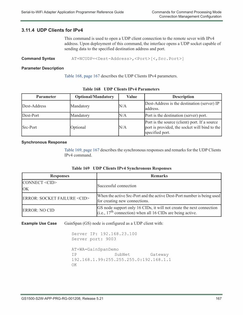
Serial-to-WiFi Adapter Application Programmer Reference Guide Commands for Command Processing ModeConnection Management Configuration
3.11.4 UDP Clients for IPv4This command is used to open a UDP client connection to the remote sever with IPv4 address. Upon deployment of this command, the interface opens a UDP socket capable of sending data to the specified destination address and port.
Command Syntax AT+NCUDP=<Dest-Address>,<Port>[<,Src.Port>]
Parameter Description
Table 168, page 167 describes the UDP Clients IPv4 parameters.
Synchronous Response
Table 169, page 167 describes the synchronous responses and remarks for the UDP Clients IPv4 command.
Example Use Case GainSpan (GS) node is configured as a UDP client with:
Server IP: 192.168.23.100Server port: 9003
AT+WA=GainSpanDemoIP SubNet Gateway192.168.1.99:255.255.255.0:192.168.1.1OK
Table 168 UDP Clients IPv4 Parameters
Parameter Optional/Mandatory Value Description
Dest-Address Mandatory N/A Dest-Address is the destination (server) IP address.
Dest-Port Mandatory N/A Port is the destination (server) port.
Src-Port Optional N/APort is the source (client) port. If a source port is provided, the socket will bind to the specified port.
Table 169 UDP Clients IPv4 Synchronous Responses
Responses RemarksCONNECT <CID>OK
Successful connection
ERROR: SOCKET FAILURE <CID> When the active Src-Port and the active Dest-Port number is being used for creating new connections.
ERROR: NO CID GS node support only 16 CIDs, it will not create the next connection (i.e., 17th connection) when all 16 CIDs are being active.
GS1500-S2W-APP-PRG-RG-001208, Release 5.21 167
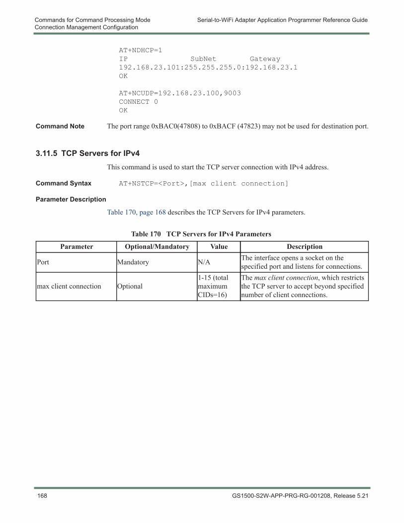
Commands for Command Processing Mode Serial-to-WiFi Adapter Application Programmer Reference GuideConnection Management Configuration
AT+NDHCP=1IP SubNet Gateway192.168.23.101:255.255.255.0:192.168.23.1OK
AT+NCUDP=192.168.23.100,9003CONNECT 0OK
Command Note The port range 0xBAC0(47808) to 0xBACF (47823) may not be used for destination port.
3.11.5 TCP Servers for IPv4This command is used to start the TCP server connection with IPv4 address.
Command Syntax AT+NSTCP=<Port>,[max client connection]
Parameter Description
Table 170, page 168 describes the TCP Servers for IPv4 parameters.
Table 170 TCP Servers for IPv4 Parameters
Parameter Optional/Mandatory Value Description
Port Mandatory N/A The interface opens a socket on the specified port and listens for connections.
max client connection Optional1-15 (total maximum CIDs=16)
The max client connection, which restricts the TCP server to accept beyond specified number of client connections.
168 GS1500-S2W-APP-PRG-RG-001208, Release 5.21
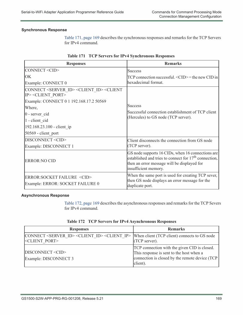
Serial-to-WiFi Adapter Application Programmer Reference Guide Commands for Command Processing ModeConnection Management Configuration
Synchronous Response
Table 171, page 169 describes the synchronous responses and remarks for the TCP Servers for IPv4 command.
Asynchronous Response
Table 172, page 169 describes the asynchronous responses and remarks for the TCP Severs for IPv4 command.
Table 171 TCP Servers for IPv4 Synchronous Responses
Responses RemarksCONNECT <CID>OKExample: CONNECT 0
SuccessTCP connection successful. <CID> = the new CID in hexadecimal format.
CONNECT <SERVER_ID> <CLIENT_ID> <CLIENT IP> <CLIENT_PORT>Example: CONNECT 0 1 192.168.17.2 50569Where,0 - server_cid1 - client_cid192.168.23.100 - client_ip50569 - client_port
SuccessSuccessful connection establishment of TCP client (Hercules) to GS node (TCP server).
DISCONNECT <CID>Example: DISCONNECT 1
Client disconnects the connection from GS node (TCP server).
ERROR:NO CID
GS node supports 16 CIDs, when 16 connections are established and tries to connect for 17th connection, then an error message will be displayed for insufficient memory.
ERROR:SOCKET FAILURE <CID>Example: ERROR: SOCKET FAILURE 0
When the same port is used for creating TCP sever, then GS node displays an error message for the duplicate port.
Table 172 TCP Servers for IPv4 Asynchronous Responses
Responses RemarksCONNECT <SERVER_ID> <CLIENT_ID> <CLIENT_IP> <CLIENT_PORT>
When client (TCP client) connects to GS node (TCP server).
DISCONNECT <CID>Example: DISCONNECT 3
TCP connection with the given CID is closed. This response is sent to the host when a connection is closed by the remote device (TCP client).
GS1500-S2W-APP-PRG-RG-001208, Release 5.21 169
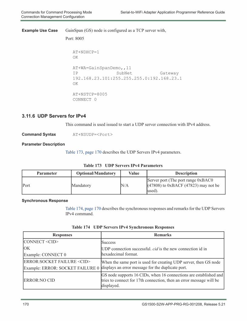
Commands for Command Processing Mode Serial-to-WiFi Adapter Application Programmer Reference GuideConnection Management Configuration
Example Use Case GainSpan (GS) node is configured as a TCP server with,
Port: 8005
AT+NDHCP=1OK
AT+WA=GainSpanDemo,,11IP SubNet Gateway192.168.23.101:255.255.255.0:192.168.23.1OK
AT+NSTCP=8005CONNECT 0
3.11.6 UDP Servers for IPv4This command is used issued to start a UDP server connection with IPv4 address.
Command Syntax AT+NSUDP=<Port>
Parameter Description
Table 173, page 170 describes the UDP Servers IPv4 parameters.
Synchronous Response
Table 174, page 170 describes the synchronous responses and remarks for the UDP Servers IPv4 command.
Table 173 UDP Servers IPv4 Parameters
Parameter Optional/Mandatory Value Description
Port Mandatory N/AServer port (The port range 0xBAC0 (47808) to 0xBACF (47823) may not be used).
Table 174 UDP Servers IPv4 Synchronous Responses
Responses RemarksCONNECT <CID>OKExample: CONNECT 0
SuccessUDP connection successful. cid is the new connection id in hexadecimal format.
ERROR:SOCKET FAILURE <CID>Example: ERROR: SOCKET FAILURE 0
When the same port is used for creating UDP server, then GS node displays an error message for the duplicate port.
ERROR:NO CIDGS node supports 16 CIDs, when 16 connections are established and tries to connect for 17th connection, then an error message will be displayed.
170 GS1500-S2W-APP-PRG-RG-001208, Release 5.21
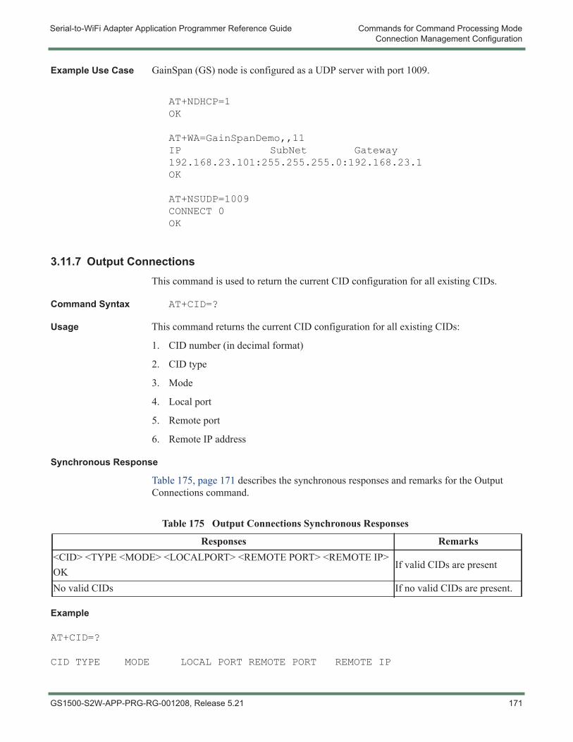
Serial-to-WiFi Adapter Application Programmer Reference Guide Commands for Command Processing ModeConnection Management Configuration
Example Use Case GainSpan (GS) node is configured as a UDP server with port 1009.
AT+NDHCP=1OK
AT+WA=GainSpanDemo,,11IP SubNet Gateway192.168.23.101:255.255.255.0:192.168.23.1OK
AT+NSUDP=1009CONNECT 0OK
3.11.7 Output ConnectionsThis command is used to return the current CID configuration for all existing CIDs.
Command Syntax AT+CID=?
Usage This command returns the current CID configuration for all existing CIDs:
1. CID number (in decimal format)
2. CID type
3. Mode
4. Local port
5. Remote port
6. Remote IP address
Synchronous Response
Table 175, page 171 describes the synchronous responses and remarks for the Output Connections command.
Example
AT+CID=?
CID TYPE MODE LOCAL PORT REMOTE PORT REMOTE IP
Table 175 Output Connections Synchronous Responses
Responses Remarks<CID> <TYPE <MODE> <LOCALPORT> <REMOTE PORT> <REMOTE IP>OK
If valid CIDs are present
No valid CIDs If no valid CIDs are present.
GS1500-S2W-APP-PRG-RG-001208, Release 5.21 171

Commands for Command Processing Mode Serial-to-WiFi Adapter Application Programmer Reference GuideConnection Management Configuration
0 UDP SERVER 1009 0 0.0.0.01 UDP CLIENT 46445 9001 192.168.23.1005 TCP CLIENT 62771 9007 192.168.23.1006 TCP SERVER 4000 0 0.0.0.03 TCP-SSL CLIENT 44499 443 192.168.2.73OK
172 GS1500-S2W-APP-PRG-RG-001208, Release 5.21
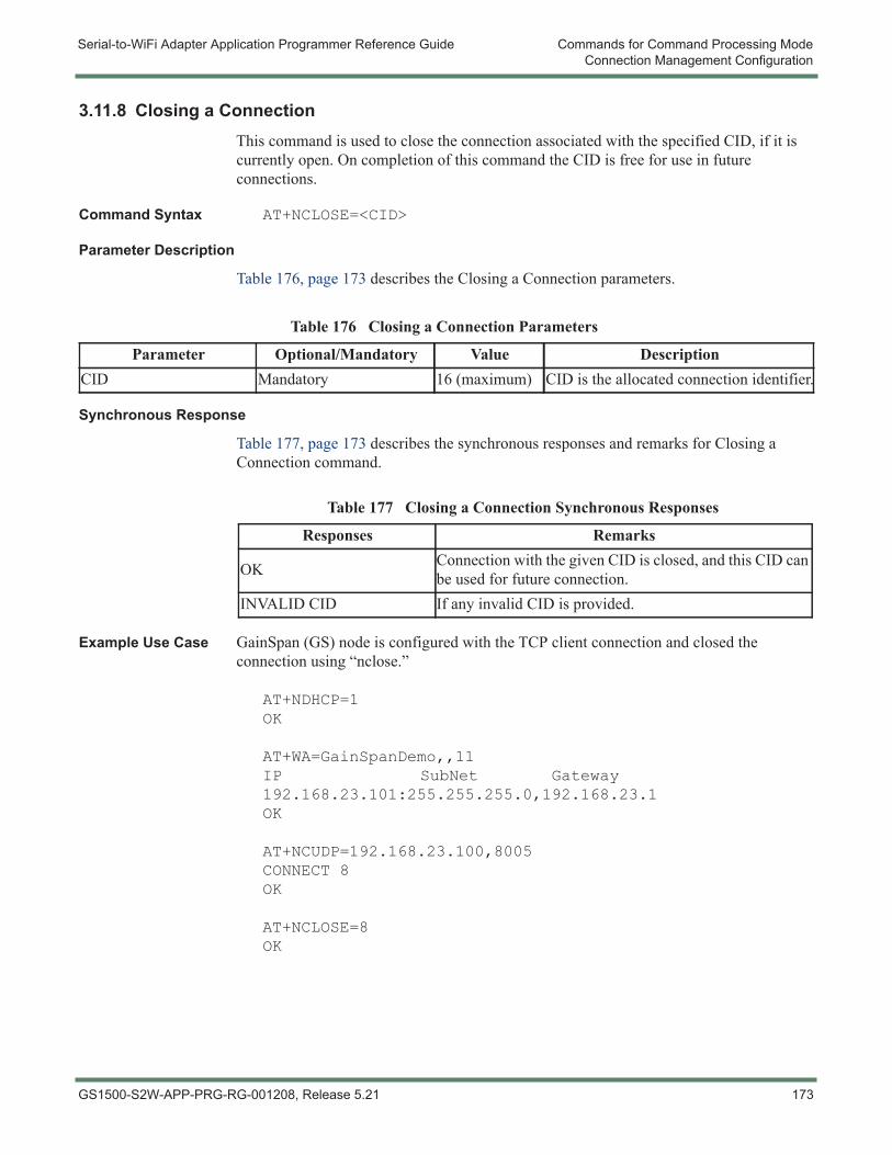
Serial-to-WiFi Adapter Application Programmer Reference Guide Commands for Command Processing ModeConnection Management Configuration
3.11.8 Closing a ConnectionThis command is used to close the connection associated with the specified CID, if it is currently open. On completion of this command the CID is free for use in future connections.
Command Syntax AT+NCLOSE=<CID>
Parameter Description
Table 176, page 173 describes the Closing a Connection parameters.
Synchronous Response
Table 177, page 173 describes the synchronous responses and remarks for Closing a Connection command.
Example Use Case GainSpan (GS) node is configured with the TCP client connection and closed the connection using “nclose.”
AT+NDHCP=1OK
AT+WA=GainSpanDemo,,11IP SubNet Gateway192.168.23.101:255.255.255.0,192.168.23.1OK
AT+NCUDP=192.168.23.100,8005CONNECT 8OK
AT+NCLOSE=8OK
Table 176 Closing a Connection Parameters
Parameter Optional/Mandatory Value DescriptionCID Mandatory 16 (maximum) CID is the allocated connection identifier.
Table 177 Closing a Connection Synchronous Responses
Responses Remarks
OK Connection with the given CID is closed, and this CID can be used for future connection.
INVALID CID If any invalid CID is provided.
GS1500-S2W-APP-PRG-RG-001208, Release 5.21 173
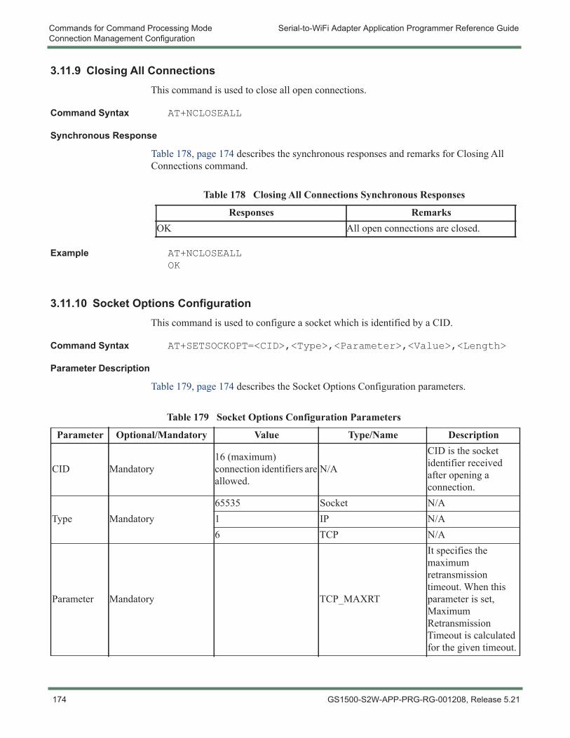
Commands for Command Processing Mode Serial-to-WiFi Adapter Application Programmer Reference GuideConnection Management Configuration
3.11.9 Closing All ConnectionsThis command is used to close all open connections.
Command Syntax AT+NCLOSEALL
Synchronous Response
Table 178, page 174 describes the synchronous responses and remarks for Closing All Connections command.
Example AT+NCLOSEALLOK
3.11.10 Socket Options ConfigurationThis command is used to configure a socket which is identified by a CID.
Command Syntax AT+SETSOCKOPT=<CID>,<Type>,<Parameter>,<Value>,<Length>
Parameter Description
Table 179, page 174 describes the Socket Options Configuration parameters.
Table 178 Closing All Connections Synchronous Responses
Responses RemarksOK All open connections are closed.
Table 179 Socket Options Configuration Parameters
Parameter Optional/Mandatory Value Type/Name Description
CID Mandatory16 (maximum) connection identifiers are allowed.
N/A
CID is the socket identifier received after opening a connection.
Type Mandatory65535 Socket N/A1 IP N/A6 TCP N/A
Parameter Mandatory TCP_MAXRT
It specifies the maximum retransmission timeout. When this parameter is set, Maximum Retransmission Timeout is calculated for the given timeout.
174 GS1500-S2W-APP-PRG-RG-001208, Release 5.21
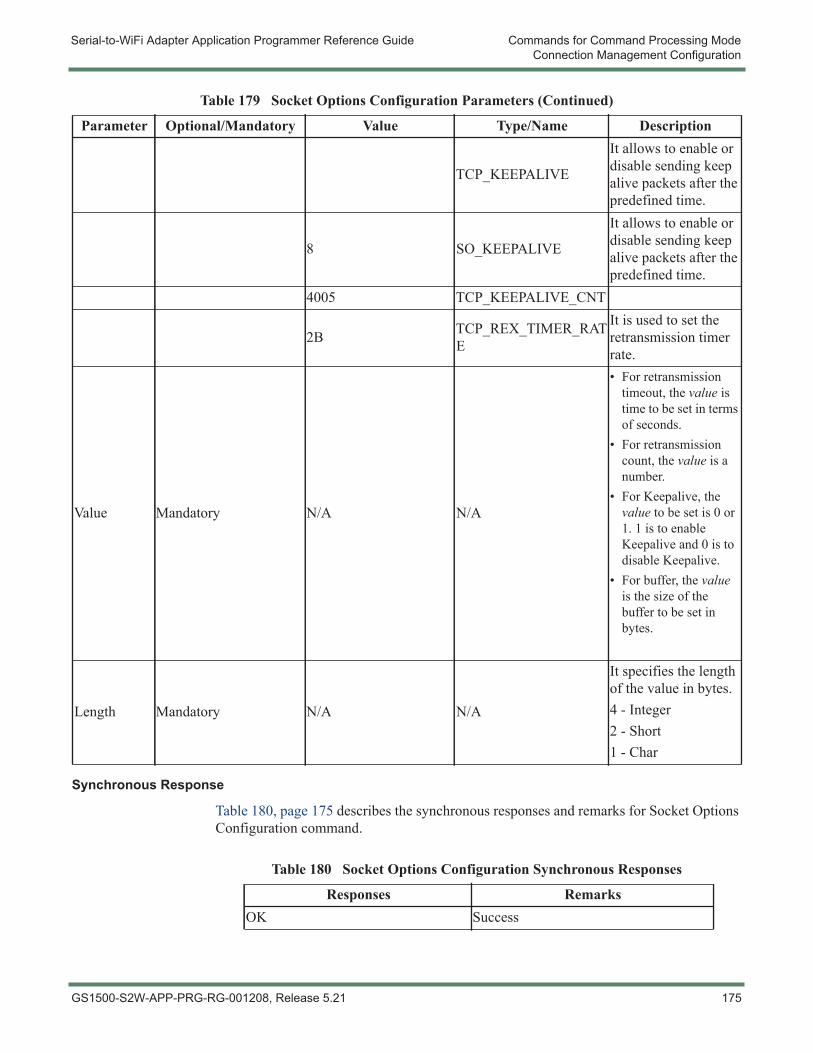
Serial-to-WiFi Adapter Application Programmer Reference Guide Commands for Command Processing ModeConnection Management Configuration
Synchronous Response
Table 180, page 175 describes the synchronous responses and remarks for Socket Options Configuration command.
TCP_KEEPALIVE
It allows to enable or disable sending keep alive packets after the predefined time.
8 SO_KEEPALIVE
It allows to enable or disable sending keep alive packets after the predefined time.
4005 TCP_KEEPALIVE_CNT
2B TCP_REX_TIMER_RATE
It is used to set the retransmission timer rate.
Value Mandatory N/A N/A
• For retransmission timeout, the value is time to be set in terms of seconds.
• For retransmission count, the value is a number.
• For Keepalive, the value to be set is 0 or 1. 1 is to enable Keepalive and 0 is to disable Keepalive.
• For buffer, the value is the size of the buffer to be set in bytes.
Length Mandatory N/A N/A
It specifies the length of the value in bytes.4 - Integer2 - Short1 - Char
Table 179 Socket Options Configuration Parameters (Continued)
Parameter Optional/Mandatory Value Type/Name Description
Table 180 Socket Options Configuration Synchronous Responses
Responses RemarksOK Success
GS1500-S2W-APP-PRG-RG-001208, Release 5.21 175
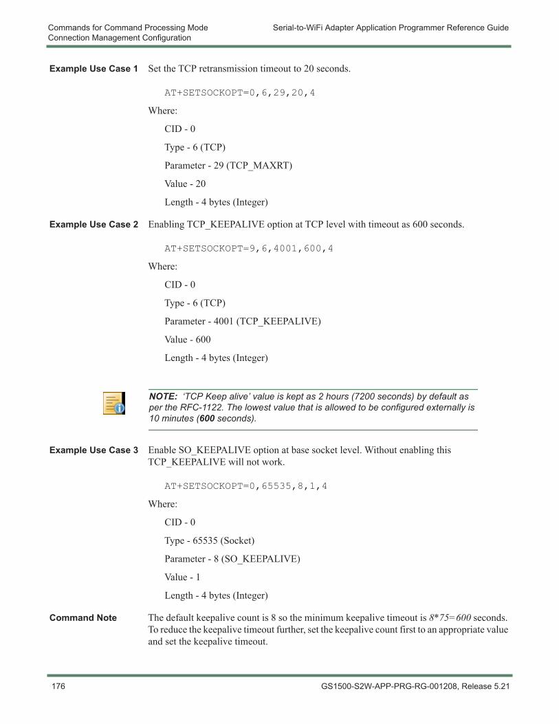
Commands for Command Processing Mode Serial-to-WiFi Adapter Application Programmer Reference GuideConnection Management Configuration
Example Use Case 1 Set the TCP retransmission timeout to 20 seconds.
AT+SETSOCKOPT=0,6,29,20,4
Where:
CID - 0
Type - 6 (TCP)
Parameter - 29 (TCP_MAXRT)
Value - 20
Length - 4 bytes (Integer)
Example Use Case 2 Enabling TCP_KEEPALIVE option at TCP level with timeout as 600 seconds.
AT+SETSOCKOPT=9,6,4001,600,4
Where:
CID - 0
Type - 6 (TCP)
Parameter - 4001 (TCP_KEEPALIVE)
Value - 600
Length - 4 bytes (Integer)
Example Use Case 3 Enable SO_KEEPALIVE option at base socket level. Without enabling this TCP_KEEPALIVE will not work.
AT+SETSOCKOPT=0,65535,8,1,4
Where:
CID - 0
Type - 65535 (Socket)
Parameter - 8 (SO_KEEPALIVE)
Value - 1
Length - 4 bytes (Integer)
Command Note The default keepalive count is 8 so the minimum keepalive timeout is 8*75=600 seconds. To reduce the keepalive timeout further, set the keepalive count first to an appropriate value and set the keepalive timeout.
NOTE: ‘TCP Keep alive’ value is kept as 2 hours (7200 seconds) by default as per the RFC-1122. The lowest value that is allowed to be configured externally is 10 minutes (600 seconds).
176 GS1500-S2W-APP-PRG-RG-001208, Release 5.21

Serial-to-WiFi Adapter Application Programmer Reference Guide Commands for Command Processing ModeConnection Management Configuration
GS node and TCP server running on a Host are both connected to an Access Point. Open a TCP client on GS node and check whether the TCP connection between the client and server is idle. If connection is idle, then TCP client (GS node) sends TCP_KEEPALIVE packets every 30 seconds which is the default Keepalive timeout.
NOTE: TCP_KEEPALIVE timeout can only be enabled or disabled, with a timeout of 30 seconds.
TCP_MAXRT)
IP_PROTOTCPTCP_MAXRT is set to 100 seconds)TCP_MAX_REXMIT
IP_PROTOTCPTCP_MAX_REXMITTCP_MAX_REXMIT is set to 40
Example Use Case 4 Set the retransmission timer rate (TCP_REX_TIMER_RATE) to 1 second.
IP_PROTOTCPTCP_REX_TIMER_RATETCP_REX_TIMER_RATE is set to 1 second
SO_RCVBUF
SO_RCVBUFSO_RCVBUF
3.11.11 SSL Connection OpenThis command is used to open an SSL connection over the TCP connection identified by the CID. For this SSL connection, the adapter uses the certificate stored in memory that is identified by the certificate name. Prior issuing this command, a valid TCP connection should exists with connection identifier as CID.
The client certificate name and client key name are required for SSL client authentication.
Command Syntax AT+SSLOPEN=<CID>,[<certificate name>, <client certificate name,<client key name>]
Parameter Description
Table 181, page 178 describes the SSL Connection Open parameters.
NOTE: Certificates and Key must be in DER format.
GS1500-S2W-APP-PRG-RG-001208, Release 5.21 177
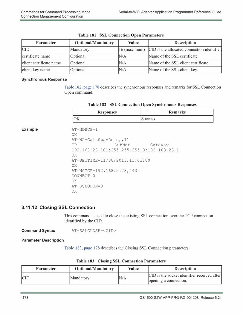
Commands for Command Processing Mode Serial-to-WiFi Adapter Application Programmer Reference GuideConnection Management Configuration
Synchronous Response
Table 182, page 178 describes the synchronous responses and remarks for SSL Connection Open command.
Example AT+NDHCP=1OKAT+WA=GainSpanDemo,,11IP SubNet Gateway192.168.23.101:255.255.255.0:192.168.23.1OKAT+SETTIME=11/30/2013,11:03:00OKAT+NCTCP=192.168.2.73,443CONNECT 0OKAT+SSLOPEN=0OK
3.11.12 Closing SSL ConnectionThis command is used to close the existing SSL connection over the TCP connection identified by the CID.
Command Syntax AT+SSLCLOSE=<CID>
Parameter Description
Table 183, page 178 describes the Closing SSL Connection parameters.
Table 181 SSL Connection Open Parameters
Parameter Optional/Mandatory Value DescriptionCID Mandatory 16 (maximum) CID is the allocated connection identifier.certificate name Optional N/A Name of the SSL certificate.client certificate name Optional N/A Name of the SSL client certificate.client key name Optional N/A Name of the SSL client key.
Table 182 SSL Connection Open Synchronous Responses
Responses RemarksOK Success
Table 183 Closing SSL Connection Parameters
Parameter Optional/Mandatory Value Description
CID Mandatory N/A CID is the socket identifier received after opening a connection.
178 GS1500-S2W-APP-PRG-RG-001208, Release 5.21
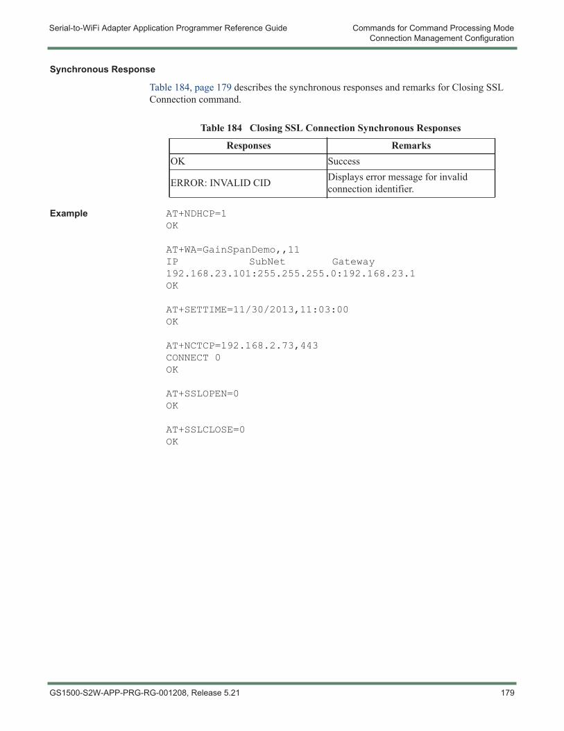
Serial-to-WiFi Adapter Application Programmer Reference Guide Commands for Command Processing ModeConnection Management Configuration
Synchronous Response
Table 184, page 179 describes the synchronous responses and remarks for Closing SSL Connection command.
Example AT+NDHCP=1OK
AT+WA=GainSpanDemo,,11IP SubNet Gateway192.168.23.101:255.255.255.0:192.168.23.1OK
AT+SETTIME=11/30/2013,11:03:00OK
AT+NCTCP=192.168.2.73,443CONNECT 0OK
AT+SSLOPEN=0OK
AT+SSLCLOSE=0OK
Table 184 Closing SSL Connection Synchronous Responses
Responses RemarksOK Success
ERROR: INVALID CID Displays error message for invalid connection identifier.
GS1500-S2W-APP-PRG-RG-001208, Release 5.21 179
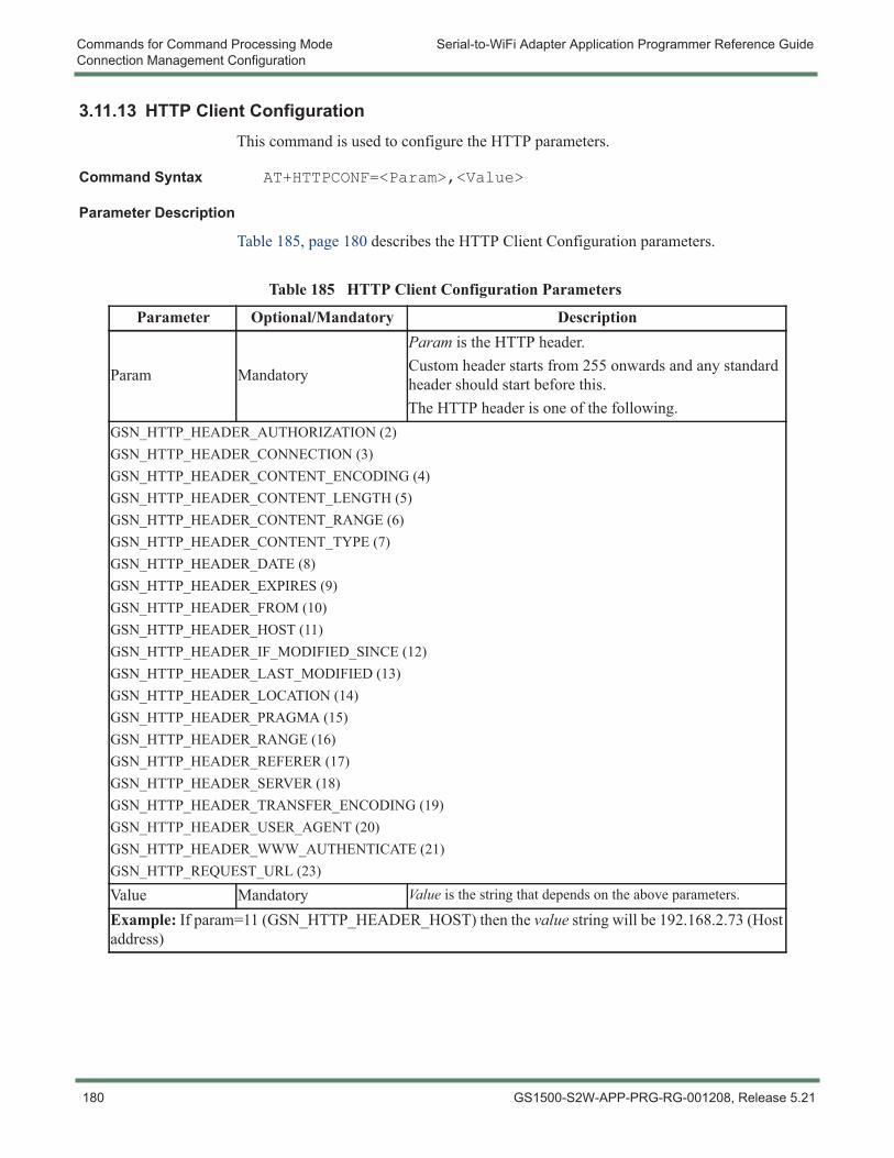
Commands for Command Processing Mode Serial-to-WiFi Adapter Application Programmer Reference GuideConnection Management Configuration
3.11.13 HTTP Client ConfigurationThis command is used to configure the HTTP parameters.
Command Syntax AT+HTTPCONF=<Param>,<Value>
Parameter Description
Table 185, page 180 describes the HTTP Client Configuration parameters.
Table 185 HTTP Client Configuration Parameters
Parameter Optional/Mandatory Description
Param Mandatory
Param is the HTTP header.Custom header starts from 255 onwards and any standard header should start before this.The HTTP header is one of the following.
GSN_HTTP_HEADER_AUTHORIZATION (2)GSN_HTTP_HEADER_CONNECTION (3)GSN_HTTP_HEADER_CONTENT_ENCODING (4)GSN_HTTP_HEADER_CONTENT_LENGTH (5)GSN_HTTP_HEADER_CONTENT_RANGE (6)GSN_HTTP_HEADER_CONTENT_TYPE (7)GSN_HTTP_HEADER_DATE (8)GSN_HTTP_HEADER_EXPIRES (9)GSN_HTTP_HEADER_FROM (10)GSN_HTTP_HEADER_HOST (11)GSN_HTTP_HEADER_IF_MODIFIED_SINCE (12)GSN_HTTP_HEADER_LAST_MODIFIED (13)GSN_HTTP_HEADER_LOCATION (14)GSN_HTTP_HEADER_PRAGMA (15)GSN_HTTP_HEADER_RANGE (16)GSN_HTTP_HEADER_REFERER (17)GSN_HTTP_HEADER_SERVER (18)GSN_HTTP_HEADER_TRANSFER_ENCODING (19)GSN_HTTP_HEADER_USER_AGENT (20)GSN_HTTP_HEADER_WWW_AUTHENTICATE (21)GSN_HTTP_REQUEST_URL (23)
Value Mandatory Value is the string that depends on the above parameters.
Example: If param=11 (GSN_HTTP_HEADER_HOST) then the value string will be 192.168.2.73 (Host address)
180 GS1500-S2W-APP-PRG-RG-001208, Release 5.21
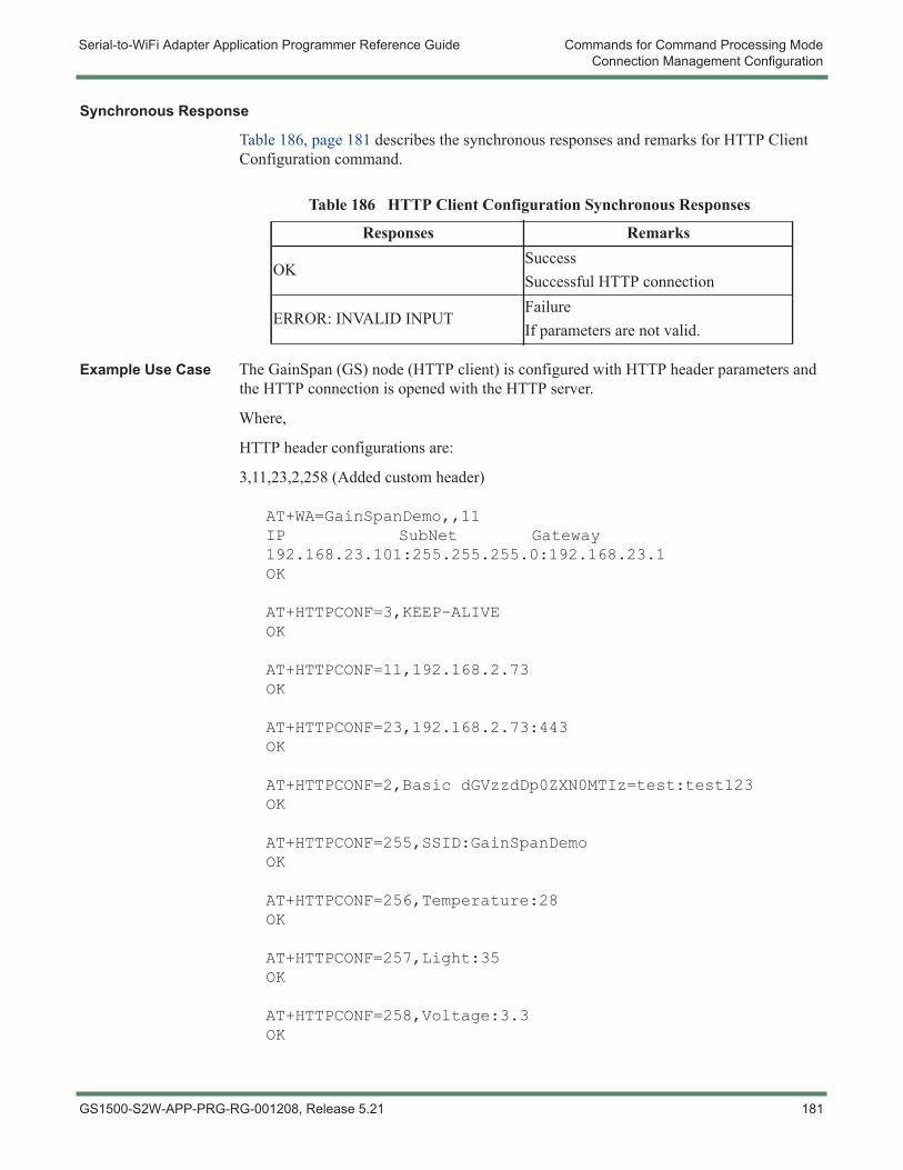
Serial-to-WiFi Adapter Application Programmer Reference Guide Commands for Command Processing ModeConnection Management Configuration
Synchronous Response
Table 186, page 181 describes the synchronous responses and remarks for HTTP Client Configuration command.
Example Use Case The GainSpan (GS) node (HTTP client) is configured with HTTP header parameters and the HTTP connection is opened with the HTTP server.
Where,
HTTP header configurations are:
3,11,23,2,258 (Added custom header)
AT+WA=GainSpanDemo,,11IP SubNet Gateway192.168.23.101:255.255.255.0:192.168.23.1OK
AT+HTTPCONF=3,KEEP-ALIVEOK
AT+HTTPCONF=11,192.168.2.73OK
AT+HTTPCONF=23,192.168.2.73:443OK
AT+HTTPCONF=2,Basic dGVzzdDp0ZXN0MTIz=test:test123OK
AT+HTTPCONF=255,SSID:GainSpanDemoOK
AT+HTTPCONF=256,Temperature:28OK
AT+HTTPCONF=257,Light:35OK
AT+HTTPCONF=258,Voltage:3.3OK
Table 186 HTTP Client Configuration Synchronous Responses
Responses Remarks
OKSuccessSuccessful HTTP connection
ERROR: INVALID INPUTFailureIf parameters are not valid.
GS1500-S2W-APP-PRG-RG-001208, Release 5.21 181

Commands for Command Processing Mode Serial-to-WiFi Adapter Application Programmer Reference GuideConnection Management Configuration
AT+HTTPOPEN=192.168.2.73,800OK
182 GS1500-S2W-APP-PRG-RG-001208, Release 5.21
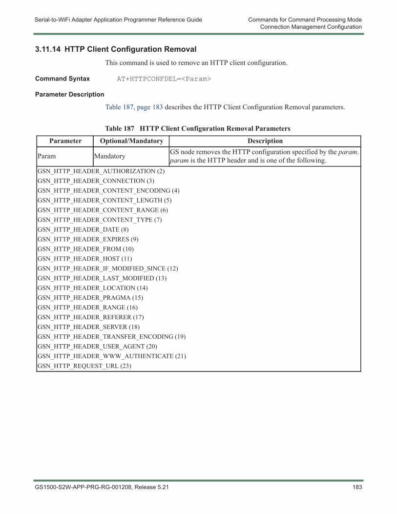
Serial-to-WiFi Adapter Application Programmer Reference Guide Commands for Command Processing ModeConnection Management Configuration
3.11.14 HTTP Client Configuration RemovalThis command is used to remove an HTTP client configuration.
Command Syntax AT+HTTPCONFDEL=<Param>
Parameter Description
Table 187, page 183 describes the HTTP Client Configuration Removal parameters.
Table 187 HTTP Client Configuration Removal Parameters
Parameter Optional/Mandatory Description
Param Mandatory GS node removes the HTTP configuration specified by the param. param is the HTTP header and is one of the following.
GSN_HTTP_HEADER_AUTHORIZATION (2)GSN_HTTP_HEADER_CONNECTION (3)GSN_HTTP_HEADER_CONTENT_ENCODING (4)GSN_HTTP_HEADER_CONTENT_LENGTH (5)GSN_HTTP_HEADER_CONTENT_RANGE (6)GSN_HTTP_HEADER_CONTENT_TYPE (7)GSN_HTTP_HEADER_DATE (8)GSN_HTTP_HEADER_EXPIRES (9)GSN_HTTP_HEADER_FROM (10)GSN_HTTP_HEADER_HOST (11)GSN_HTTP_HEADER_IF_MODIFIED_SINCE (12)GSN_HTTP_HEADER_LAST_MODIFIED (13)GSN_HTTP_HEADER_LOCATION (14)GSN_HTTP_HEADER_PRAGMA (15)GSN_HTTP_HEADER_RANGE (16)GSN_HTTP_HEADER_REFERER (17)GSN_HTTP_HEADER_SERVER (18)GSN_HTTP_HEADER_TRANSFER_ENCODING (19)GSN_HTTP_HEADER_USER_AGENT (20)GSN_HTTP_HEADER_WWW_AUTHENTICATE (21)GSN_HTTP_REQUEST_URL (23)
GS1500-S2W-APP-PRG-RG-001208, Release 5.21 183
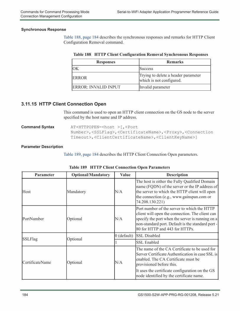
Commands for Command Processing Mode Serial-to-WiFi Adapter Application Programmer Reference GuideConnection Management Configuration
Synchronous Response
Table 188, page 184 describes the synchronous responses and remarks for HTTP Client Configuration Removal command.
3.11.15 HTTP Client Connection OpenThis command is used to open an HTTP client connection on the GS node to the server specified by the host name and IP address.
Command Syntax AT+HTTPOPEN=<host >[,<Port Number>,<SSLFlag>,<CertificateName>,<Proxy>,<Connection Timeout>,<ClientCertificateName>,<ClientKeyName>]
Parameter Description
Table 189, page 184 describes the HTTP Client Connection Open parameters.
Table 188 HTTP Client Configuration Removal Synchronous Responses
Responses RemarksOK Success
ERROR Trying to delete a header parameter which is not configured.
ERROR: INVALID INPUT Invalid parameter
Table 189 HTTP Client Connection Open Parameters
Parameter Optional/Mandatory Value Description
Host Mandatory N/A
The host is either the Fully Qualified Domain name (FQDN) of the server or the IP address of the server to which the HTTP client will open the connection (e.g., www.gainspan.com or 74.208.130.221)
PortNumber Optional N/A
Port number of the server to which the HTTP client will open the connection. The client can specify the port when the server is running on a non-standard port. Default is the standard port - 80 for HTTP and 443 for HTTPs.
SSLFlag Optional0 (default) SSL Disabled1 SSL Enabled
CertificateName Optional N/A
The name of the CA Certificate to be used for Server Certificate Authentication in case SSL is enabled. The CA Certificate must be provisioned before this.It uses the certificate configuration on the GS node identified by the certificate name.
184 GS1500-S2W-APP-PRG-RG-001208, Release 5.21
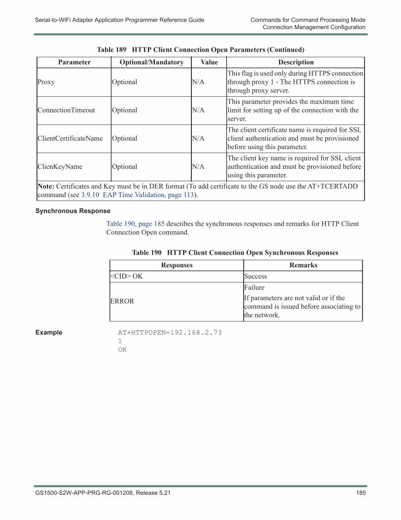
Serial-to-WiFi Adapter Application Programmer Reference Guide Commands for Command Processing ModeConnection Management Configuration
Synchronous Response
Table 190, page 185 describes the synchronous responses and remarks for HTTP Client Connection Open command.
Example AT+HTTPOPEN=192.168.2.731OK
Proxy Optional N/AThis flag is used only during HTTPS connection through proxy 1 - The HTTPS connection is through proxy server.
ConnectionTimeout Optional N/AThis parameter provides the maximum time limit for setting up of the connection with the server.
ClientCertificateName Optional N/AThe client certificate name is required for SSL client authentication and must be provisioned before using this parameter.
ClienKeyName Optional N/AThe client key name is required for SSL client authentication and must be provisioned before using this parameter.
Note: Certificates and Key must be in DER format (To add certificate to the GS node use the AT+TCERTADD command (see 3.9.10 EAP Time Validation, page 113).
Table 189 HTTP Client Connection Open Parameters (Continued)
Parameter Optional/Mandatory Value Description
Table 190 HTTP Client Connection Open Synchronous Responses
Responses Remarks<CID> OK Success
ERROR
FailureIf parameters are not valid or if the command is issued before associating to the network.
GS1500-S2W-APP-PRG-RG-001208, Release 5.21 185
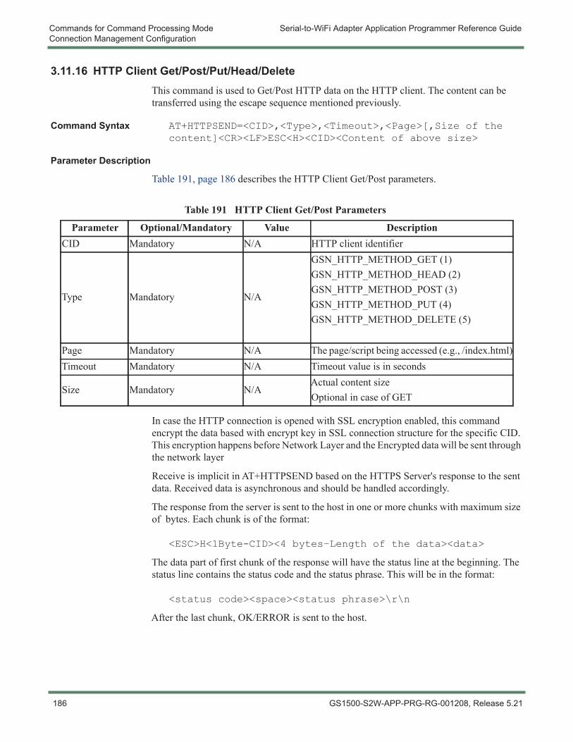
Commands for Command Processing Mode Serial-to-WiFi Adapter Application Programmer Reference GuideConnection Management Configuration
3.11.16 HTTP Client Get/Post/Put/Head/DeleteThis command is used to Get/Post HTTP data on the HTTP client. The content can be transferred using the escape sequence mentioned previously.
Command Syntax AT+HTTPSEND=<CID>,<Type>,<Timeout>,<Page>[,Size of the content]<CR><LF>ESC<H><CID><Content of above size>
Parameter Description
Table 191, page 186 describes the HTTP Client Get/Post parameters.
In case the HTTP connection is opened with SSL encryption enabled, this command encrypt the data based with encrypt key in SSL connection structure for the specific CID. This encryption happens before Network Layer and the Encrypted data will be sent through the network layer
Receive is implicit in AT+HTTPSEND based on the HTTPS Server's response to the sent data. Received data is asynchronous and should be handled accordingly.
The response from the server is sent to the host in one or more chunks with maximum size of bytes. Each chunk is of the format:
<ESC>H<1Byte-CID><4 bytes–Length of the data><data>
The data part of first chunk of the response will have the status line at the beginning. The status line contains the status code and the status phrase. This will be in the format:
<status code><space><status phrase>\r\n
After the last chunk, OK/ERROR is sent to the host.
Table 191 HTTP Client Get/Post Parameters
Parameter Optional/Mandatory Value DescriptionCID Mandatory N/A HTTP client identifier
Type Mandatory N/A
GSN_HTTP_METHOD_GET (1)GSN_HTTP_METHOD_HEAD (2)GSN_HTTP_METHOD_POST (3)GSN_HTTP_METHOD_PUT (4)GSN_HTTP_METHOD_DELETE (5)
Page Mandatory N/A The page/script being accessed (e.g., /index.html)Timeout Mandatory N/A Timeout value is in seconds
Size Mandatory N/AActual content sizeOptional in case of GET
186 GS1500-S2W-APP-PRG-RG-001208, Release 5.21
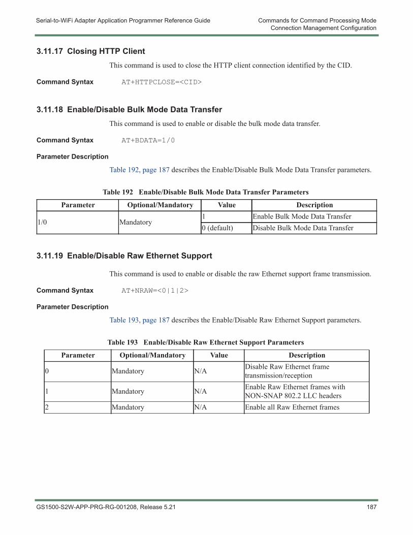
Serial-to-WiFi Adapter Application Programmer Reference Guide Commands for Command Processing ModeConnection Management Configuration
3.11.17 Closing HTTP ClientThis command is used to close the HTTP client connection identified by the CID.
Command Syntax AT+HTTPCLOSE=<CID>
3.11.18 Enable/Disable Bulk Mode Data TransferThis command is used to enable or disable the bulk mode data transfer.
Command Syntax AT+BDATA=1/0
Parameter Description
Table 192, page 187 describes the Enable/Disable Bulk Mode Data Transfer parameters.
3.11.19 Enable/Disable Raw Ethernet Support
This command is used to enable or disable the raw Ethernet support frame transmission.
Command Syntax AT+NRAW=<0|1|2>
Parameter Description
Table 193, page 187 describes the Enable/Disable Raw Ethernet Support parameters.
Table 192 Enable/Disable Bulk Mode Data Transfer Parameters
Parameter Optional/Mandatory Value Description
1/0 Mandatory1 Enable Bulk Mode Data Transfer0 (default) Disable Bulk Mode Data Transfer
Table 193 Enable/Disable Raw Ethernet Support Parameters
Parameter Optional/Mandatory Value Description
0 Mandatory N/A Disable Raw Ethernet frame transmission/reception
1 Mandatory N/A Enable Raw Ethernet frames with NON-SNAP 802.2 LLC headers
2 Mandatory N/A Enable all Raw Ethernet frames
GS1500-S2W-APP-PRG-RG-001208, Release 5.21 187

Commands for Command Processing Mode Serial-to-WiFi Adapter Application Programmer Reference GuideConnection Management Configuration
When selection 1 is chosen, 802.3 frames are presumed to include an 802.2 header which is not a SNAP header. These frames are used, for example, for sending BACNET data over Ethernet. A frame of this type has the format:
<ESC>R:<Length>:<DstAddr><SrcAddr>0x0000<Raw-Payload>
On the receiving side, frames with 802.2 headers which are not a SNAP header, are sent directly to serial interface and DATA Frames with UDP port range 0xBAC0 to 0xBACF will be ignored.
When selection 2 is chosen, the 802.2 header (presumed to be a SNAP header) is removed, and a raw Ethernet II frame payload is expected, as per the format below:
<ESC>R:<Length>:<DstAddr><SrcAddr><EtherType><Raw-Payload>
On the receiving side, frames with 802.2 headers that are not SNAP headers and DATA Frames with UDP port ranges 0xBAC0 to 0xBACF are sent directly to serial interface.
This frame format is used for sending IP data over BACNET.
Length is size of DstAddr, SrcAddr, EtherType and Payload.
If the Adapter receives DATA Frames, where the 802.2 LLC headers’ SSAP and DSAP are not both 0xAA, these frames are presumed to be 802.3 frames, and are sent to the Adapter’s serial port as described above.
If the Adapter received DATA Frames with UDP port range 0xBAC0 to 0xBACF, they are presumed to be BACNET/IP frames, BacNet IP frame, and are sent to the Adapter’s serial port as described above.
188 GS1500-S2W-APP-PRG-RG-001208, Release 5.21
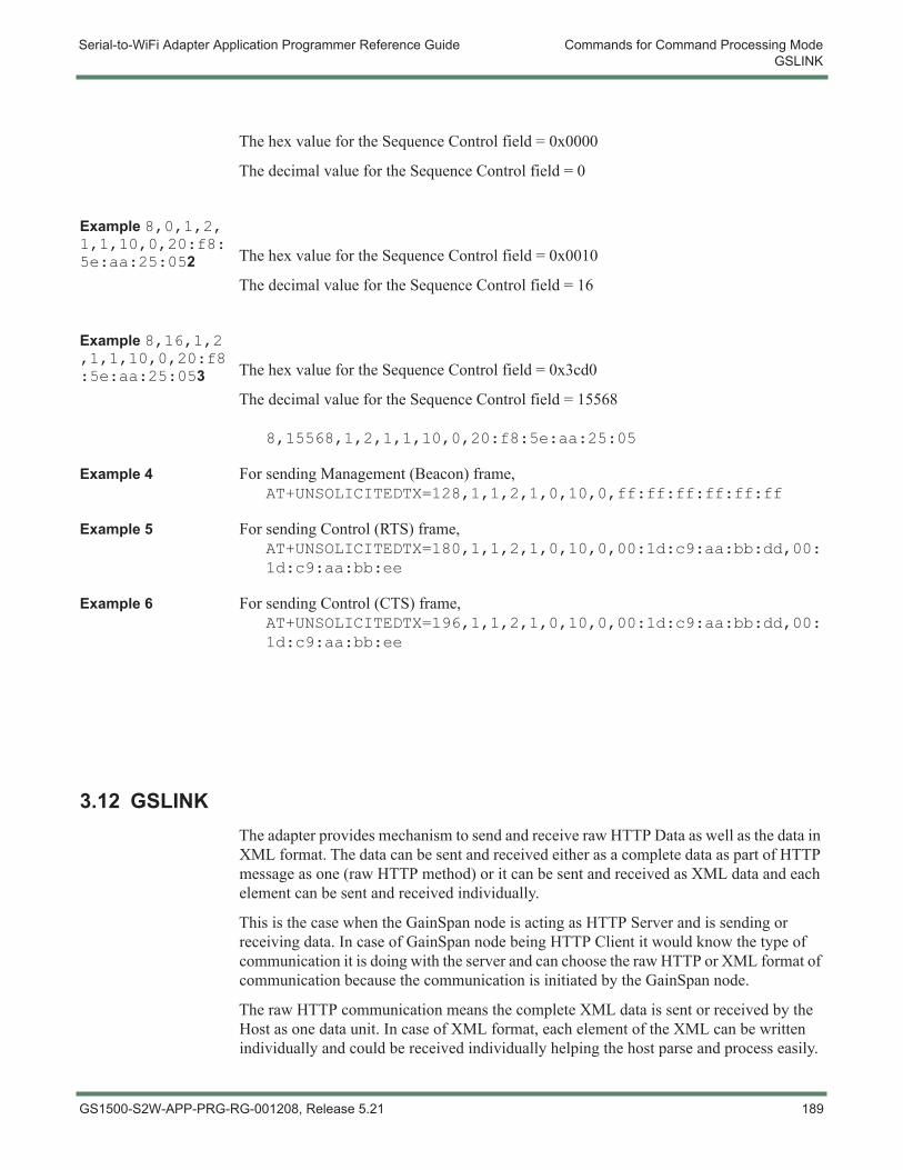
Serial-to-WiFi Adapter Application Programmer Reference Guide Commands for Command Processing ModeGSLINK
The hex value for the Sequence Control field = 0x0000
The decimal value for the Sequence Control field = 0
Example 8,0,1,2,1,1,10,0,20:f8:5e:aa:25:052 The hex value for the Sequence Control field = 0x0010
The decimal value for the Sequence Control field = 16
Example 8,16,1,2,1,1,10,0,20:f8:5e:aa:25:053 The hex value for the Sequence Control field = 0x3cd0
The decimal value for the Sequence Control field = 15568
8,15568,1,2,1,1,10,0,20:f8:5e:aa:25:05
Example 4 For sending Management (Beacon) frame,AT+UNSOLICITEDTX=128,1,1,2,1,0,10,0,ff:ff:ff:ff:ff:ff
Example 5 For sending Control (RTS) frame,AT+UNSOLICITEDTX=180,1,1,2,1,0,10,0,00:1d:c9:aa:bb:dd,00:1d:c9:aa:bb:ee
Example 6 For sending Control (CTS) frame,AT+UNSOLICITEDTX=196,1,1,2,1,0,10,0,00:1d:c9:aa:bb:dd,00:1d:c9:aa:bb:ee
3.12 GSLINK The adapter provides mechanism to send and receive raw HTTP Data as well as the data in XML format. The data can be sent and received either as a complete data as part of HTTP message as one (raw HTTP method) or it can be sent and received as XML data and each element can be sent and received individually.
This is the case when the GainSpan node is acting as HTTP Server and is sending or receiving data. In case of GainSpan node being HTTP Client it would know the type of communication it is doing with the server and can choose the raw HTTP or XML format of communication because the communication is initiated by the GainSpan node.
The raw HTTP communication means the complete XML data is sent or received by the Host as one data unit. In case of XML format, each element of the XML can be written individually and could be received individually helping the host parse and process easily.
GS1500-S2W-APP-PRG-RG-001208, Release 5.21 189
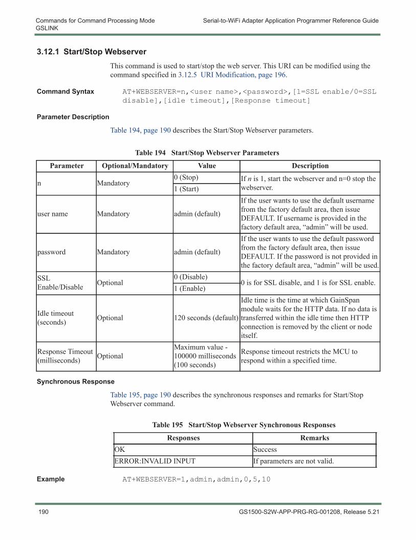
Commands for Command Processing Mode Serial-to-WiFi Adapter Application Programmer Reference GuideGSLINK
3.12.1 Start/Stop WebserverThis command is used to start/stop the web server. This URI can be modified using the command specified in 3.12.5 URI Modification, page 196.
Command Syntax AT+WEBSERVER=n,<user name>,<password>,[1=SSL enable/0=SSL disable],[idle timeout],[Response timeout]
Parameter Description
Table 194, page 190 describes the Start/Stop Webserver parameters.
Synchronous Response
Table 195, page 190 describes the synchronous responses and remarks for Start/Stop Webserver command.
Example AT+WEBSERVER=1,admin,admin,0,5,10
Table 194 Start/Stop Webserver Parameters
Parameter Optional/Mandatory Value Description
n Mandatory0 (Stop) If n is 1, start the webserver and n=0 stop the
webserver.1 (Start)
user name Mandatory admin (default)
If the user wants to use the default username from the factory default area, then issue DEFAULT. If username is provided in the factory default area, “admin” will be used.
password Mandatory admin (default)
If the user wants to use the default password from the factory default area, then issue DEFAULT. If the password is not provided in the factory default area, “admin” will be used.
SSL Enable/Disable Optional
0 (Disable)0 is for SSL disable, and 1 is for SSL enable.
1 (Enable)
Idle timeout (seconds) Optional 120 seconds (default)
Idle time is the time at which GainSpan module waits for the HTTP data. If no data is transferred within the idle time then HTTP connection is removed by the client or node itself.
Response Timeout (milliseconds) Optional
Maximum value - 100000 milliseconds (100 seconds)
Response timeout restricts the MCU to respond within a specified time.
Table 195 Start/Stop Webserver Synchronous Responses
Responses RemarksOK SuccessERROR:INVALID INPUT If parameters are not valid.
190 GS1500-S2W-APP-PRG-RG-001208, Release 5.21

Serial-to-WiFi Adapter Application Programmer Reference Guide Commands for Command Processing ModeGSLINK
OK
GS1500-S2W-APP-PRG-RG-001208, Release 5.21 191
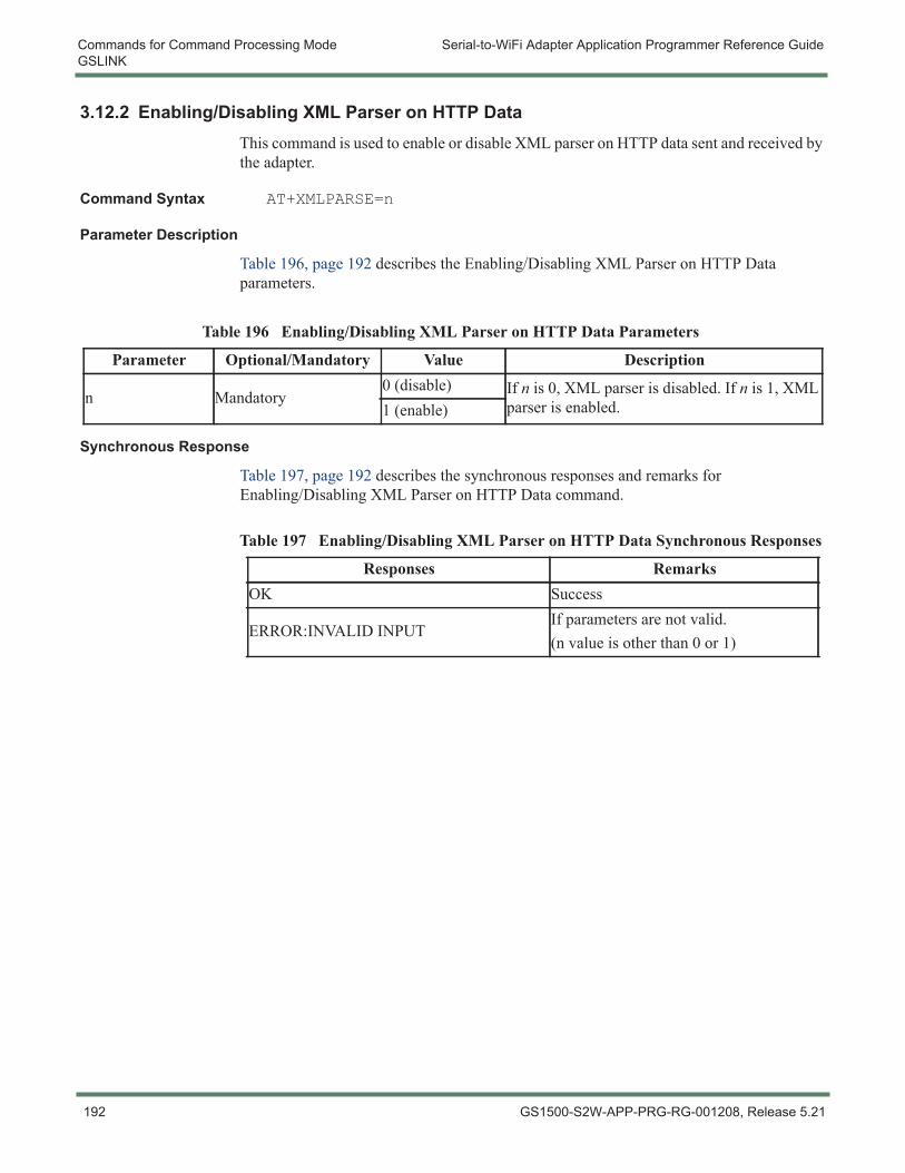
Commands for Command Processing Mode Serial-to-WiFi Adapter Application Programmer Reference GuideGSLINK
3.12.2 Enabling/Disabling XML Parser on HTTP DataThis command is used to enable or disable XML parser on HTTP data sent and received by the adapter.
Command Syntax AT+XMLPARSE=n
Parameter Description
Table 196, page 192 describes the Enabling/Disabling XML Parser on HTTP Data parameters.
Synchronous Response
Table 197, page 192 describes the synchronous responses and remarks for Enabling/Disabling XML Parser on HTTP Data command.
Table 196 Enabling/Disabling XML Parser on HTTP Data Parameters
Parameter Optional/Mandatory Value Description
n Mandatory0 (disable) If n is 0, XML parser is disabled. If n is 1, XML
parser is enabled.1 (enable)
Table 197 Enabling/Disabling XML Parser on HTTP Data Synchronous Responses
Responses RemarksOK Success
ERROR:INVALID INPUTIf parameters are not valid.(n value is other than 0 or 1)
192 GS1500-S2W-APP-PRG-RG-001208, Release 5.21
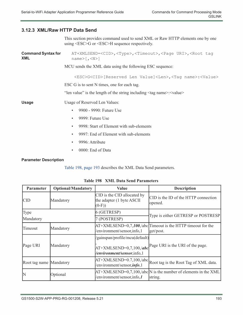
Serial-to-WiFi Adapter Application Programmer Reference Guide Commands for Command Processing ModeGSLINK
3.12.3 XML/Raw HTTP Data SendThis section provides command used to send XML or Raw HTTP elements one by one using <ESC>G or <ESC>H sequence respectively.
Command Syntax for XML
AT+XMLSEND=<CID>,<Type>,<Timeout>,<Page URI>,<Root tag name>[,<N>]
MCU sends the XML data using the following ESC sequence:
<ESC>G<CID>[Reserved Len Value]<Len>,<Tag name>:<Value>
ESC G is to sent N times, one for each tag.
“len value” is the length of the string including <tag name>:<value>
Usage Usage of Reserved Len Values:
• 9900 - 9990: Future Use
• 9999: Future Use
• 9998: Start of Element with sub-elements
• 9997: End of Element with sub-elements
• 9996: Attribute
• 0000: End of Data
Parameter Description
Table 198, page 193 describes the XML Data Send parameters.
Table 198 XML Data Send Parameters
Parameter Optional/Mandatory Value Description
CID MandatoryCID is the CID allocated by the adapter (1 byte ASCII (0-F))
CID is the ID of the HTTP connection opened.
TypeMandatory
6 (GETRESP)Type is either GETRESP or POSTRESP
7 (POSTRESP)
Timeout Mandatory AT+XMLSEND=0,7,100,/abc/environment/sensor,info,1
Timeout is the HTTP timeout for the get/post.
Page URI Mandatory
/gainspan/profile/mcu(default), AT+XMLSEND=0,7,100,/abc/environment/sensor,info,1
Page URI is the URI of the page.
Root tag name Mandatory AT+XMLSEND=0.7,100,/abc/environment/sensor,info,1 Root tag is the Root Tag of XML data.
N Optional AT+XMLSEND=0,7,100,/abc/environment/sensor,info,1
N is the number of elements in the XML string.
GS1500-S2W-APP-PRG-RG-001208, Release 5.21 193
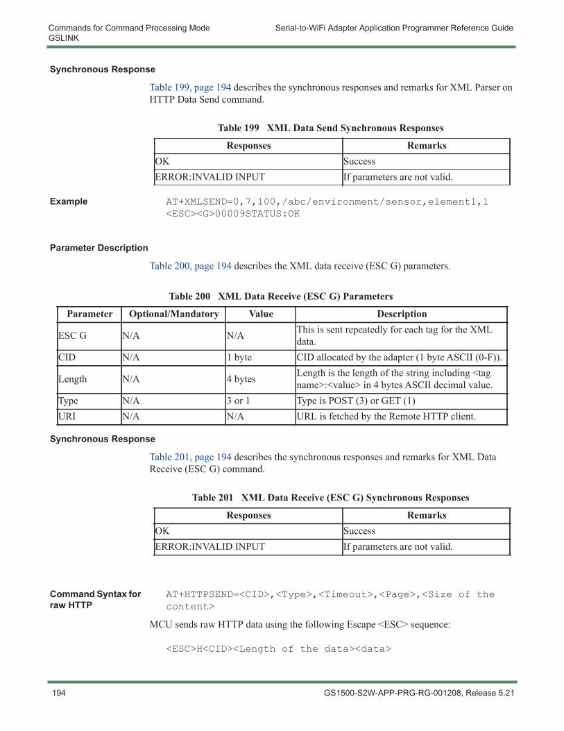
Commands for Command Processing Mode Serial-to-WiFi Adapter Application Programmer Reference GuideGSLINK
Synchronous Response
Table 199, page 194 describes the synchronous responses and remarks for XML Parser on HTTP Data Send command.
Example AT+XMLSEND=0,7,100,/abc/environment/sensor,element1,1<ESC><G>00009STATUS:OK
Parameter Description
Table 200, page 194 describes the XML data receive (ESC G) parameters.
Synchronous Response
Table 201, page 194 describes the synchronous responses and remarks for XML Data Receive (ESC G) command.
Command Syntax for raw HTTP
AT+HTTPSEND=<CID>,<Type>,<Timeout>,<Page>,<Size of the content>
MCU sends raw HTTP data using the following Escape <ESC> sequence:
<ESC>H<CID><Length of the data><data>
Table 199 XML Data Send Synchronous Responses
Responses RemarksOK SuccessERROR:INVALID INPUT If parameters are not valid.
Table 200 XML Data Receive (ESC G) Parameters
Parameter Optional/Mandatory Value Description
ESC G N/A N/A This is sent repeatedly for each tag for the XML data.
CID N/A 1 byte CID allocated by the adapter (1 byte ASCII (0-F)).
Length N/A 4 bytes Length is the length of the string including <tag name>:<value> in 4 bytes ASCII decimal value.
Type N/A 3 or 1 Type is POST (3) or GET (1)URI N/A N/A URL is fetched by the Remote HTTP client.
Table 201 XML Data Receive (ESC G) Synchronous Responses
Responses RemarksOK SuccessERROR:INVALID INPUT If parameters are not valid.
194 GS1500-S2W-APP-PRG-RG-001208, Release 5.21
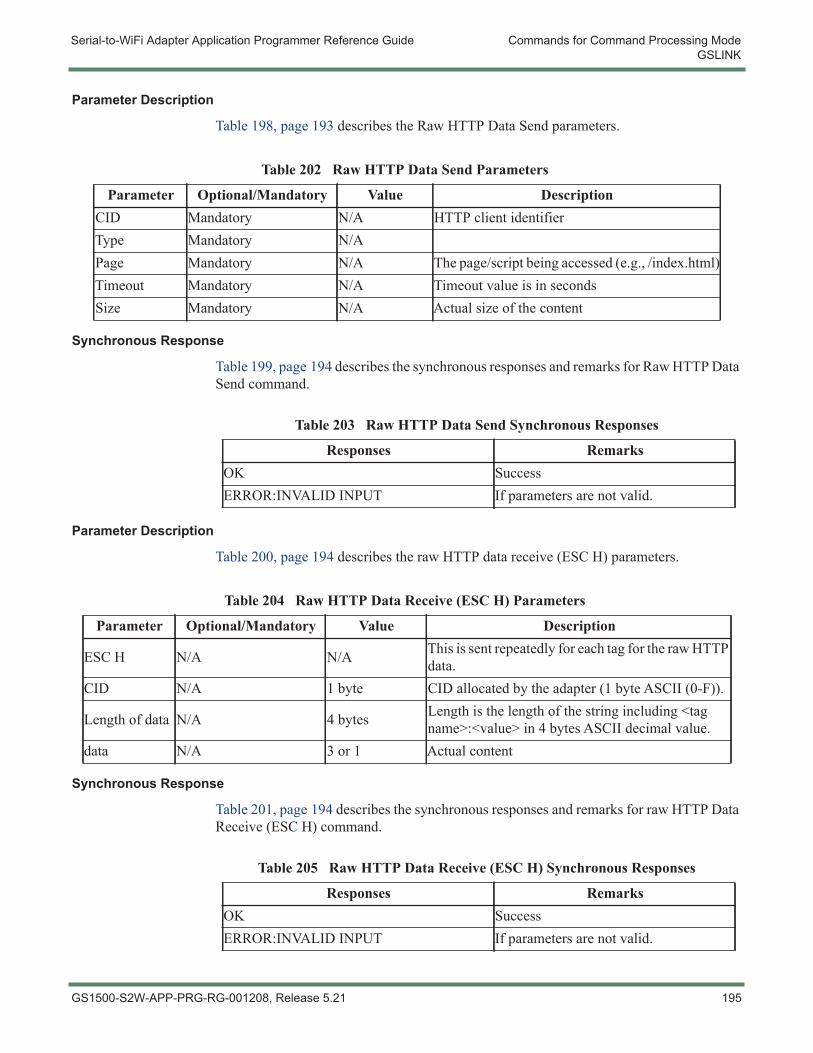
Serial-to-WiFi Adapter Application Programmer Reference Guide Commands for Command Processing ModeGSLINK
Parameter Description
Table 198, page 193 describes the Raw HTTP Data Send parameters.
Synchronous Response
Table 199, page 194 describes the synchronous responses and remarks for Raw HTTP Data Send command.
Parameter Description
Table 200, page 194 describes the raw HTTP data receive (ESC H) parameters.
Synchronous Response
Table 201, page 194 describes the synchronous responses and remarks for raw HTTP Data Receive (ESC H) command.
Table 202 Raw HTTP Data Send Parameters
Parameter Optional/Mandatory Value DescriptionCID Mandatory N/A HTTP client identifierType Mandatory N/APage Mandatory N/A The page/script being accessed (e.g., /index.html)Timeout Mandatory N/A Timeout value is in secondsSize Mandatory N/A Actual size of the content
Table 203 Raw HTTP Data Send Synchronous Responses
Responses RemarksOK SuccessERROR:INVALID INPUT If parameters are not valid.
Table 204 Raw HTTP Data Receive (ESC H) Parameters
Parameter Optional/Mandatory Value Description
ESC H N/A N/A This is sent repeatedly for each tag for the raw HTTP data.
CID N/A 1 byte CID allocated by the adapter (1 byte ASCII (0-F)).
Length of data N/A 4 bytes Length is the length of the string including <tag name>:<value> in 4 bytes ASCII decimal value.
data N/A 3 or 1 Actual content
Table 205 Raw HTTP Data Receive (ESC H) Synchronous Responses
Responses RemarksOK SuccessERROR:INVALID INPUT If parameters are not valid.
GS1500-S2W-APP-PRG-RG-001208, Release 5.21 195
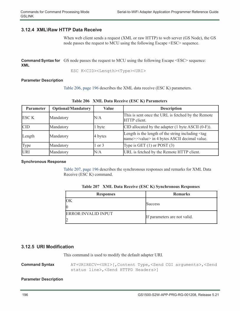
Commands for Command Processing Mode Serial-to-WiFi Adapter Application Programmer Reference GuideGSLINK
3.12.4 XML\Raw HTTP Data ReceiveWhen web client sends a request (XML or raw HTTP) to web server (GS Node), the GS node passes the request to MCU using the following Escape <ESC> sequence.
Command Syntax for XML
GS node passes the request to MCU using the following Escape <ESC> sequence:
ESC K<CID><Length><Type><URI>
Parameter Description
Table 206, page 196 describes the XML data receive (ESC K) parameters.
Synchronous Response
Table 207, page 196 describes the synchronous responses and remarks for XML Data Receive (ESC K) command.
3.12.5 URI ModificationThis command is used to modify the default adapter URI.
Command Syntax AT+URIRECV=<URI>[,Content Type,<Send CGI arguments>,<Send status line>,<Send HTTPD Headers>]
Parameter Description
Table 206 XML Data Receive (ESC K) Parameters
Parameter Optional/Mandatory Value Description
ESC K Mandatory N/A This is sent once the URL is fetched by the Remote HTTP client.
CID Mandatory 1 byte CID allocated by the adapter (1 byte ASCII (0-F)).
Length Mandatory 4 bytes Length is the length of the string including <tag name>:<value> in 4 bytes ASCII decimal value.
Type Mandatory 1 or 3 Type is GET (1) or POST (3)URI Mandatory N/A URL is fetched by the Remote HTTP client.
Table 207 XML Data Receive (ESC K) Synchronous Responses
Responses RemarksOK0
Success
ERROR:INVALID INPUT2
If parameters are not valid.
196 GS1500-S2W-APP-PRG-RG-001208, Release 5.21
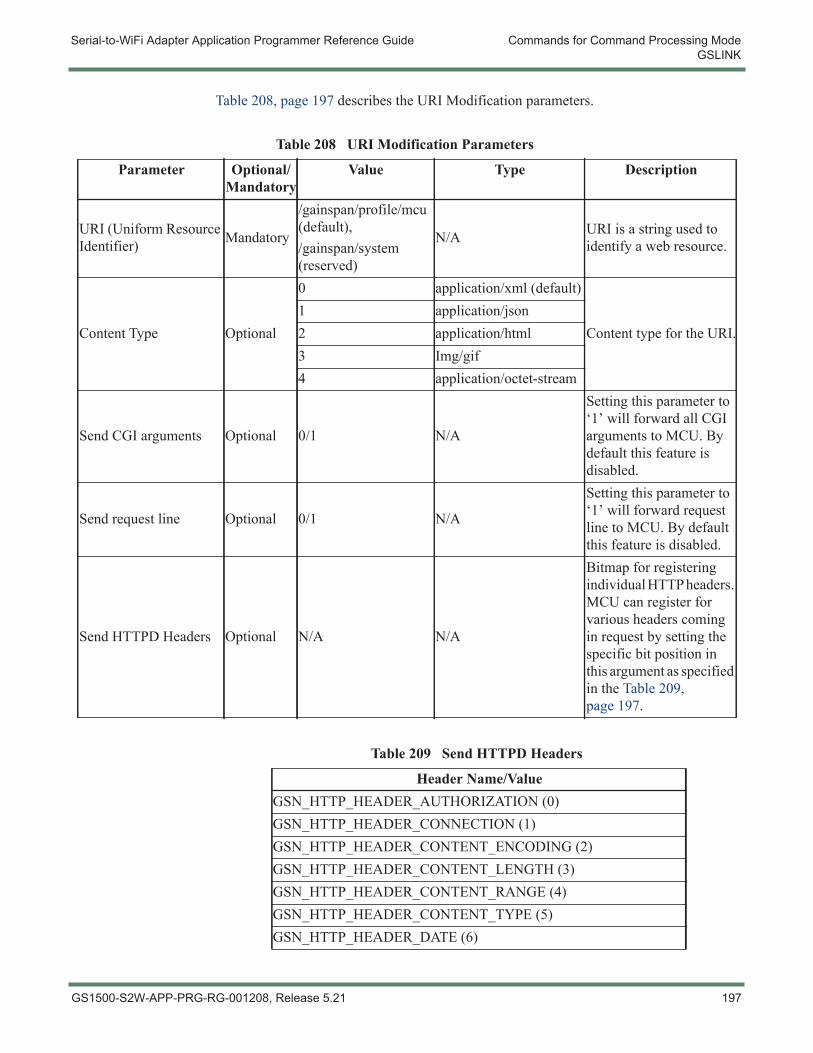
Serial-to-WiFi Adapter Application Programmer Reference Guide Commands for Command Processing ModeGSLINK
Table 208, page 197 describes the URI Modification parameters.
Table 208 URI Modification Parameters
Parameter Optional/Mandatory
Value Type Description
URI (Uniform Resource Identifier) Mandatory
/gainspan/profile/mcu (default),/gainspan/system (reserved)
N/A URI is a string used to identify a web resource.
Content Type Optional
0 application/xml (default)
Content type for the URI.1 application/json2 application/html3 Img/gif4 application/octet-stream
Send CGI arguments Optional 0/1 N/A
Setting this parameter to ‘1’ will forward all CGI arguments to MCU. By default this feature is disabled.
Send request line Optional 0/1 N/A
Setting this parameter to ‘1’ will forward request line to MCU. By default this feature is disabled.
Send HTTPD Headers Optional N/A N/A
Bitmap for registering individual HTTP headers. MCU can register for various headers coming in request by setting the specific bit position in this argument as specified in the Table 209, page 197.
Table 209 Send HTTPD Headers
Header Name/ValueGSN_HTTP_HEADER_AUTHORIZATION (0)GSN_HTTP_HEADER_CONNECTION (1)GSN_HTTP_HEADER_CONTENT_ENCODING (2)GSN_HTTP_HEADER_CONTENT_LENGTH (3)GSN_HTTP_HEADER_CONTENT_RANGE (4)GSN_HTTP_HEADER_CONTENT_TYPE (5)GSN_HTTP_HEADER_DATE (6)
GS1500-S2W-APP-PRG-RG-001208, Release 5.21 197
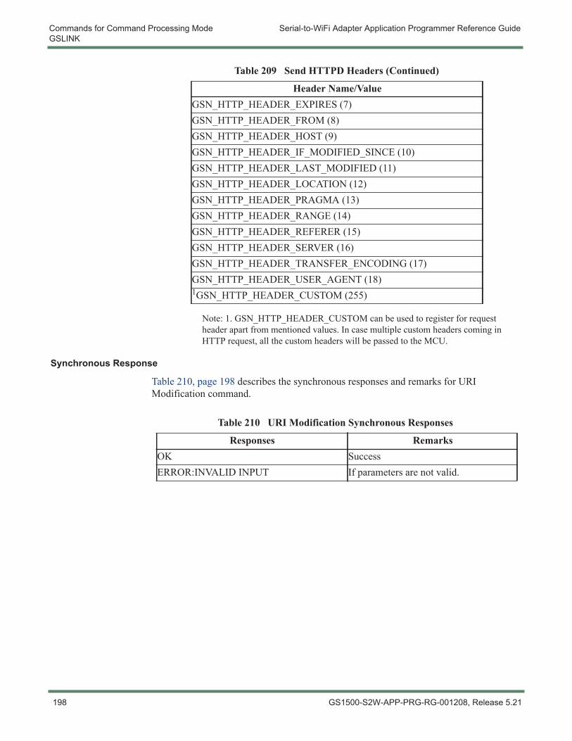
Commands for Command Processing Mode Serial-to-WiFi Adapter Application Programmer Reference GuideGSLINK
Note: 1. GSN_HTTP_HEADER_CUSTOM can be used to register for request header apart from mentioned values. In case multiple custom headers coming in HTTP request, all the custom headers will be passed to the MCU.
Synchronous Response
Table 210, page 198 describes the synchronous responses and remarks for URI Modification command.
GSN_HTTP_HEADER_EXPIRES (7)GSN_HTTP_HEADER_FROM (8)GSN_HTTP_HEADER_HOST (9)GSN_HTTP_HEADER_IF_MODIFIED_SINCE (10)GSN_HTTP_HEADER_LAST_MODIFIED (11)GSN_HTTP_HEADER_LOCATION (12)GSN_HTTP_HEADER_PRAGMA (13)GSN_HTTP_HEADER_RANGE (14)GSN_HTTP_HEADER_REFERER (15)GSN_HTTP_HEADER_SERVER (16)GSN_HTTP_HEADER_TRANSFER_ENCODING (17)GSN_HTTP_HEADER_USER_AGENT (18)1GSN_HTTP_HEADER_CUSTOM (255)
Table 209 Send HTTPD Headers (Continued)
Header Name/Value
Table 210 URI Modification Synchronous Responses
Responses RemarksOK SuccessERROR:INVALID INPUT If parameters are not valid.
198 GS1500-S2W-APP-PRG-RG-001208, Release 5.21
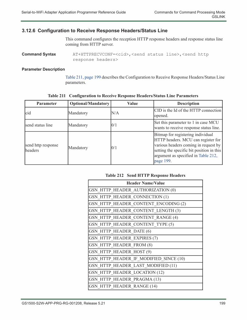
Serial-to-WiFi Adapter Application Programmer Reference Guide Commands for Command Processing ModeGSLINK
3.12.6 Configuration to Receive Response Headers/Status LineThis command configures the reception HTTP response headers and response status line coming from HTTP server.
Command Syntax AT+HTTPRECVCONF=<cid>,<send status line>,<send http response headers>
Parameter Description
Table 211, page 199 describes the Configuration to Receive Response Headers/Status Line parameters.
Table 211 Configuration to Receive Response Headers/Status Line Parameters
Parameter Optional/Mandatory Value Description
cid Mandatory N/A CID is the Id of the HTTP connection opened.
send status line Mandatory 0/1 Set this parameter to 1 in case MCU wants to receive response status line.
send http response headers Mandatory 0/1
Bitmap for registering individual HTTP headers. MCU can register for various headers coming in request by setting the specific bit position in this argument as specified in Table 212, page 199.
Table 212 Send HTTP Response Headers
Header Name/ValueGSN_HTTP_HEADER_AUTHORIZATION (0)GSN_HTTP_HEADER_CONNECTION (1)GSN_HTTP_HEADER_CONTENT_ENCODING (2)GSN_HTTP_HEADER_CONTENT_LENGTH (3)GSN_HTTP_HEADER_CONTENT_RANGE (4)GSN_HTTP_HEADER_CONTENT_TYPE (5)GSN_HTTP_HEADER_DATE (6)GSN_HTTP_HEADER_EXPIRES (7)GSN_HTTP_HEADER_FROM (8)GSN_HTTP_HEADER_HOST (9)GSN_HTTP_HEADER_IF_MODIFIED_SINCE (10)GSN_HTTP_HEADER_LAST_MODIFIED (11)GSN_HTTP_HEADER_LOCATION (12)GSN_HTTP_HEADER_PRAGMA (13)GSN_HTTP_HEADER_RANGE (14)
GS1500-S2W-APP-PRG-RG-001208, Release 5.21 199
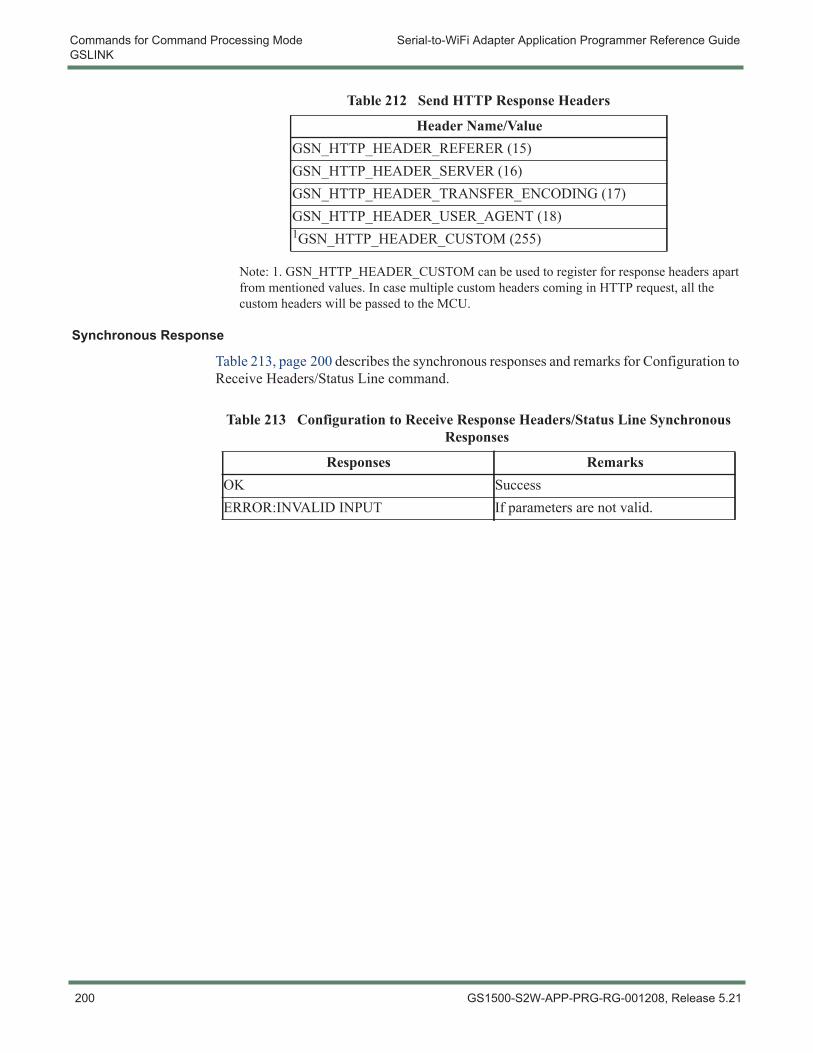
Commands for Command Processing Mode Serial-to-WiFi Adapter Application Programmer Reference GuideGSLINK
Note: 1. GSN_HTTP_HEADER_CUSTOM can be used to register for response headers apart from mentioned values. In case multiple custom headers coming in HTTP request, all the custom headers will be passed to the MCU.
Synchronous Response
Table 213, page 200 describes the synchronous responses and remarks for Configuration to Receive Headers/Status Line command.
GSN_HTTP_HEADER_REFERER (15)GSN_HTTP_HEADER_SERVER (16)GSN_HTTP_HEADER_TRANSFER_ENCODING (17)GSN_HTTP_HEADER_USER_AGENT (18)1GSN_HTTP_HEADER_CUSTOM (255)
Table 212 Send HTTP Response Headers
Header Name/Value
Table 213 Configuration to Receive Response Headers/Status Line Synchronous Responses
Responses RemarksOK SuccessERROR:INVALID INPUT If parameters are not valid.
200 GS1500-S2W-APP-PRG-RG-001208, Release 5.21

Serial-to-WiFi Adapter Application Programmer Reference Guide Commands for Command Processing ModeGSLINK
GS1500-S2W-APP-PRG-RG-001208, Release 5.21 201
Commands for Command Processing Mode Serial-to-WiFi Adapter Application Programmer Reference GuidePower State Management
3.13 Power State Management
3.13.1 Enable/Disable SoC Deep SleepThis command is used to enable the GainSpan SoCs power-saving Deep Sleep processor mode.
Command Syntax AT+PSDPSLEEP
Usage When enabled, the SoC will enter the power-saving Deep Sleep mode when no actions are pending. In Deep Sleep mode, the processor clock is turned off, and SoC power consumption is reduced to less than 1 mW (about 0.1 mA at 1.8 V).
The processor can be awakened by sending data on the serial port from the host. However, several milliseconds are required to stabilize the clock oscillator when the system awakens from Deep Sleep. Since the clock oscillator must stabilize before data can be read, the initial data will not be received; “dummy” (discardable) characters or commands should be sent until an indication is received from the application.
Command Response These commands do not return any response code to the serial interface. The S2W adapter sends the message “Out of Deep Sleep” along with the standard response once it comes out from deep sleep.
Parameter Description
A similar command can be used to enable the deep sleep with a timeout and alarm. Table 214, page 203 describes the Enable/Disable SoC Deep Sleep parameters.
AT+PSDPSLEEP=[<timeout>,<ALARM1 POL>,<ALARM2 POL>
NOTE: Other components external to the SoC may continue to dissipate power during this time, unless measures are taken to ensure that they are also off or disabled.
202 GS1500-S2W-APP-PRG-RG-001208, Release 5.21
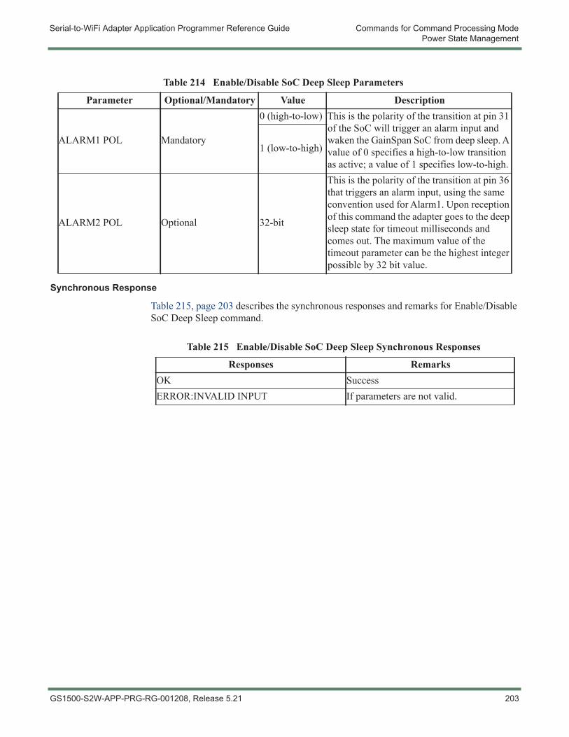
Serial-to-WiFi Adapter Application Programmer Reference Guide Commands for Command Processing ModePower State Management
Synchronous Response
Table 215, page 203 describes the synchronous responses and remarks for Enable/Disable SoC Deep Sleep command.
Table 214 Enable/Disable SoC Deep Sleep Parameters
Parameter Optional/Mandatory Value Description
ALARM1 POL Mandatory
0 (high-to-low) This is the polarity of the transition at pin 31 of the SoC will trigger an alarm input and waken the GainSpan SoC from deep sleep. A value of 0 specifies a high-to-low transition as active; a value of 1 specifies low-to-high.
1 (low-to-high)
ALARM2 POL Optional 32-bit
This is the polarity of the transition at pin 36 that triggers an alarm input, using the same convention used for Alarm1. Upon reception of this command the adapter goes to the deep sleep state for timeout milliseconds and comes out. The maximum value of the timeout parameter can be the highest integer possible by 32 bit value.
Table 215 Enable/Disable SoC Deep Sleep Synchronous Responses
Responses RemarksOK SuccessERROR:INVALID INPUT If parameters are not valid.
GS1500-S2W-APP-PRG-RG-001208, Release 5.21 203
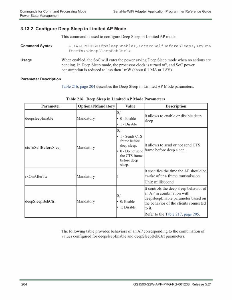
Commands for Command Processing Mode Serial-to-WiFi Adapter Application Programmer Reference GuidePower State Management
3.13.2 Configure Deep Sleep in Limited AP ModeThis command is used to configure Deep Sleep in Limited AP mode.
Command Syntax AT+WAPPSCFG=<dpsleepEnable>,<ctsToSelfBeforeSleep>,<rxOnAfterTx><deepSleepBehCtrl>
Usage When enabled, the SoC will enter the power saving Deep Sleep mode when no actions are pending. In Deep Sleep mode, the processor clock is turned off, and SoC power consumption is reduced to less then 1mW (about 0.1 MA at 1.8V).
Parameter Description
Table 216, page 204 describes the Deep Sleep in Limited AP Mode parameters.
The following table provides behaviors of an AP corresponding to the combination of values configured for deepsleepEnable and deepSleepBehCtrl parameters.
Table 216 Deep Sleep in Limited AP Mode Parameters
Parameter Optional/Mandatory Value Description
deepsleepEnable Mandatory0,1• 0 - Enable• 1 - Disable
It allows to enable or disable deep sleep.
ctsToSelfBeforeSleep Mandatory
0,1• 1 - Sends CTS
frame before deep sleep.
• 0 - Do not send the CTS frame before deep sleep.
It allows to send or not send CTS frame before deep sleep.
rxOnAfterTx Mandatory 1It specifies the time the AP should be awake after a frame transmission.Unit: millisecond
deepSleepBehCtrl Mandatory0,1• 0: Enable• 1: Disable
It controls the deep sleep behavior of an AP in combination with deepsleepEnable parameter based on the behavior of the clients connected to it.Refer to the Table 217, page 205.
204 GS1500-S2W-APP-PRG-RG-001208, Release 5.21
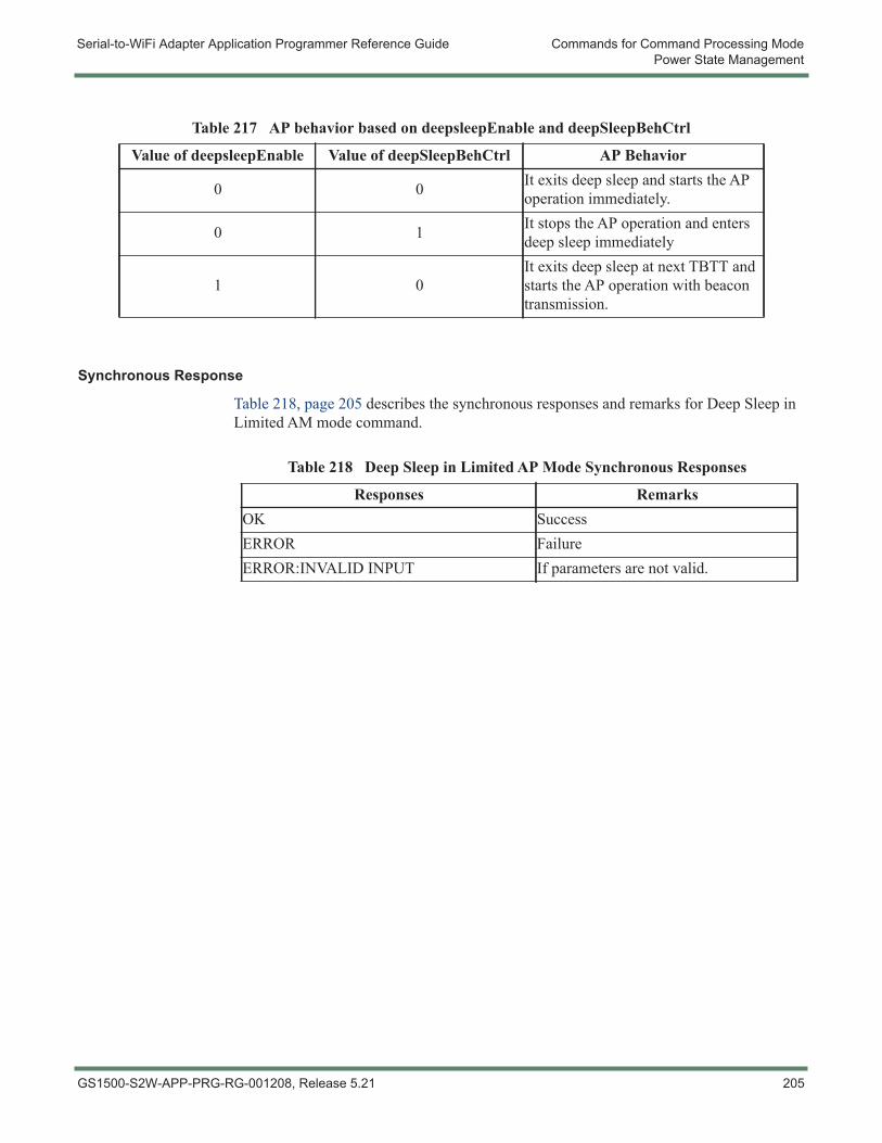
Serial-to-WiFi Adapter Application Programmer Reference Guide Commands for Command Processing ModePower State Management
Synchronous Response
Table 218, page 205 describes the synchronous responses and remarks for Deep Sleep in Limited AM mode command.
Table 217 AP behavior based on deepsleepEnable and deepSleepBehCtrl
Value of deepsleepEnable Value of deepSleepBehCtrl AP Behavior
0 0 It exits deep sleep and starts the AP operation immediately.
0 1 It stops the AP operation and enters deep sleep immediately
1 0It exits deep sleep at next TBTT and starts the AP operation with beacon transmission.
Table 218 Deep Sleep in Limited AP Mode Synchronous Responses
Responses RemarksOK SuccessERROR FailureERROR:INVALID INPUT If parameters are not valid.
GS1500-S2W-APP-PRG-RG-001208, Release 5.21 205
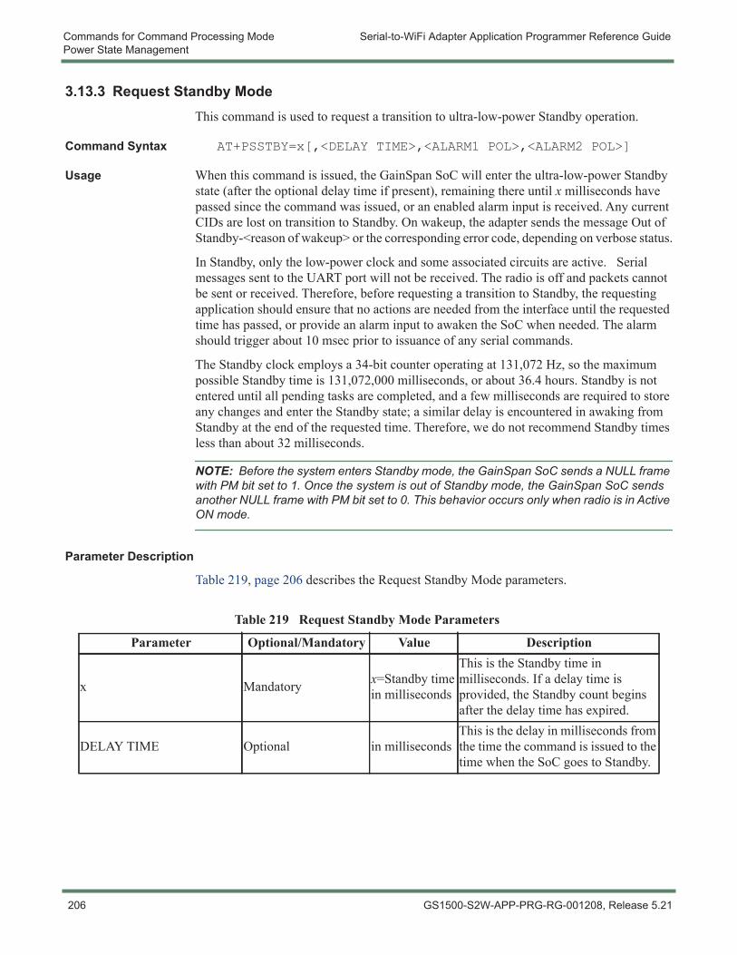
Commands for Command Processing Mode Serial-to-WiFi Adapter Application Programmer Reference GuidePower State Management
3.13.3 Request Standby ModeThis command is used to request a transition to ultra-low-power Standby operation.
Command Syntax AT+PSSTBY=x[,<DELAY TIME>,<ALARM1 POL>,<ALARM2 POL>]
Usage When this command is issued, the GainSpan SoC will enter the ultra-low-power Standby state (after the optional delay time if present), remaining there until x milliseconds have passed since the command was issued, or an enabled alarm input is received. Any current CIDs are lost on transition to Standby. On wakeup, the adapter sends the message Out of Standby-<reason of wakeup> or the corresponding error code, depending on verbose status.
In Standby, only the low-power clock and some associated circuits are active. Serial messages sent to the UART port will not be received. The radio is off and packets cannot be sent or received. Therefore, before requesting a transition to Standby, the requesting application should ensure that no actions are needed from the interface until the requested time has passed, or provide an alarm input to awaken the SoC when needed. The alarm should trigger about 10 msec prior to issuance of any serial commands.
The Standby clock employs a 34-bit counter operating at 131,072 Hz, so the maximum possible Standby time is 131,072,000 milliseconds, or about 36.4 hours. Standby is not entered until all pending tasks are completed, and a few milliseconds are required to store any changes and enter the Standby state; a similar delay is encountered in awaking from Standby at the end of the requested time. Therefore, we do not recommend Standby times less than about 32 milliseconds.
NOTE: Before the system enters Standby mode, the GainSpan SoC sends a NULL frame with PM bit set to 1. Once the system is out of Standby mode, the GainSpan SoC sends another NULL frame with PM bit set to 0. This behavior occurs only when radio is in Active ON mode.
Parameter Description
Table 219, page 206 describes the Request Standby Mode parameters.
Table 219 Request Standby Mode Parameters
Parameter Optional/Mandatory Value Description
x Mandatory x=Standby time in milliseconds
This is the Standby time in milliseconds. If a delay time is provided, the Standby count begins after the delay time has expired.
DELAY TIME Optional in millisecondsThis is the delay in milliseconds from the time the command is issued to the time when the SoC goes to Standby.
206 GS1500-S2W-APP-PRG-RG-001208, Release 5.21
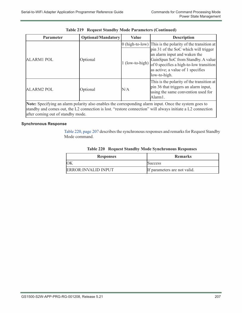
Serial-to-WiFi Adapter Application Programmer Reference Guide Commands for Command Processing ModePower State Management
Synchronous Response
Table 220, page 207 describes the synchronous responses and remarks for Request Standby Mode command.
ALARM1 POL Optional
0 (high-to-low) This is the polarity of the transition at pin 31 of the SoC which will trigger an alarm input and waken the GainSpan SoC from Standby. A value of 0 specifies a high-to-low transition as active; a value of 1 specifies low-to-high.
1 (low-to-high)
ALARM2 POL Optional N/A
This is the polarity of the transition at pin 36 that triggers an alarm input, using the same convention used for Alarm1.
Note: Specifying an alarm polarity also enables the corresponding alarm input. Once the system goes to standby and comes out, the L2 connection is lost. “restore connection” will always initiate a L2 connection after coming out of standby mode.
Table 219 Request Standby Mode Parameters (Continued)
Parameter Optional/Mandatory Value Description
Table 220 Request Standby Mode Synchronous Responses
Responses RemarksOK SuccessERROR:INVALID INPUT If parameters are not valid.
GS1500-S2W-APP-PRG-RG-001208, Release 5.21 207
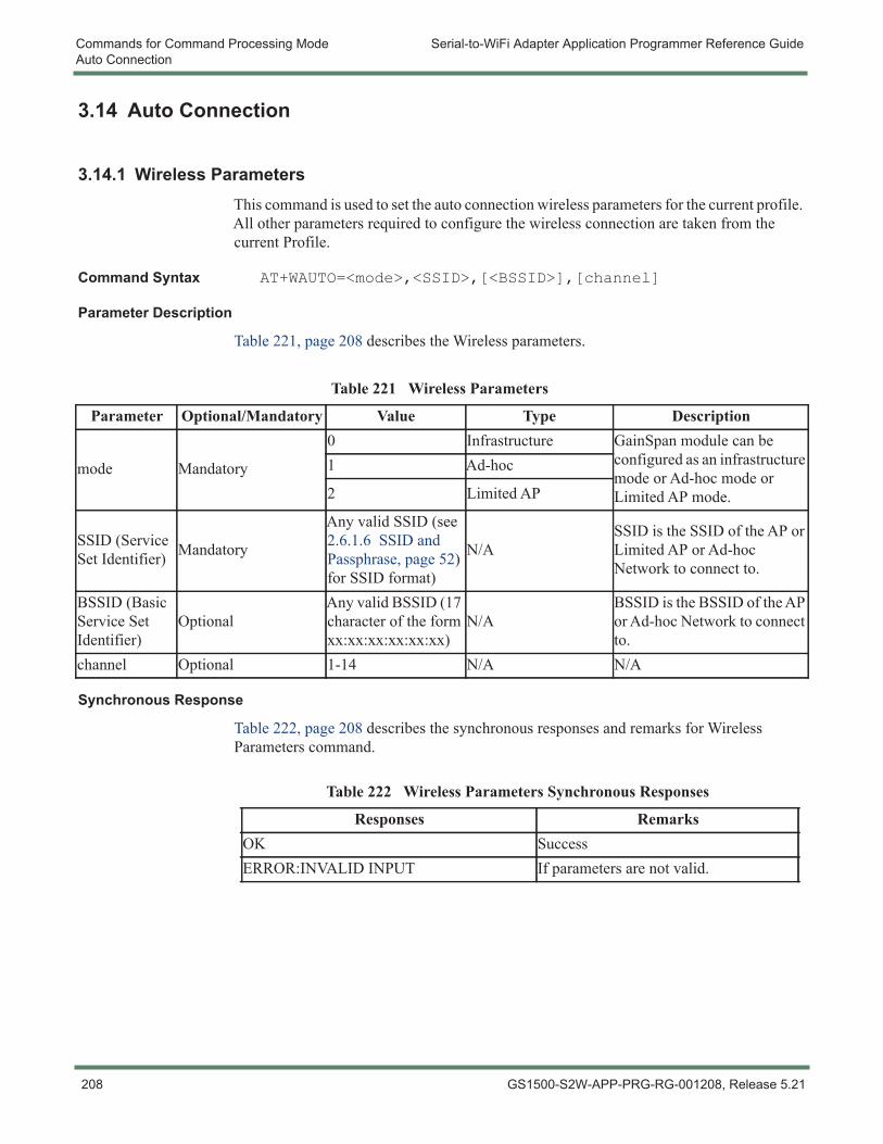
Commands for Command Processing Mode Serial-to-WiFi Adapter Application Programmer Reference GuideAuto Connection
3.14 Auto Connection
3.14.1 Wireless ParametersThis command is used to set the auto connection wireless parameters for the current profile. All other parameters required to configure the wireless connection are taken from the current Profile.
Command Syntax AT+WAUTO=<mode>,<SSID>,[<BSSID>],[channel]
Parameter Description
Table 221, page 208 describes the Wireless parameters.
Synchronous Response
Table 222, page 208 describes the synchronous responses and remarks for Wireless Parameters command.
Table 221 Wireless Parameters
Parameter Optional/Mandatory Value Type Description
mode Mandatory
0 Infrastructure GainSpan module can be configured as an infrastructure mode or Ad-hoc mode or Limited AP mode.
1 Ad-hoc
2 Limited AP
SSID (Service Set Identifier) Mandatory
Any valid SSID (see 2.6.1.6 SSID and Passphrase, page 52) for SSID format)
N/ASSID is the SSID of the AP or Limited AP or Ad-hoc Network to connect to.
BSSID (Basic Service Set Identifier)
OptionalAny valid BSSID (17 character of the form xx:xx:xx:xx:xx:xx)
N/ABSSID is the BSSID of the AP or Ad-hoc Network to connect to.
channel Optional 1-14 N/A N/A
Table 222 Wireless Parameters Synchronous Responses
Responses RemarksOK SuccessERROR:INVALID INPUT If parameters are not valid.
208 GS1500-S2W-APP-PRG-RG-001208, Release 5.21
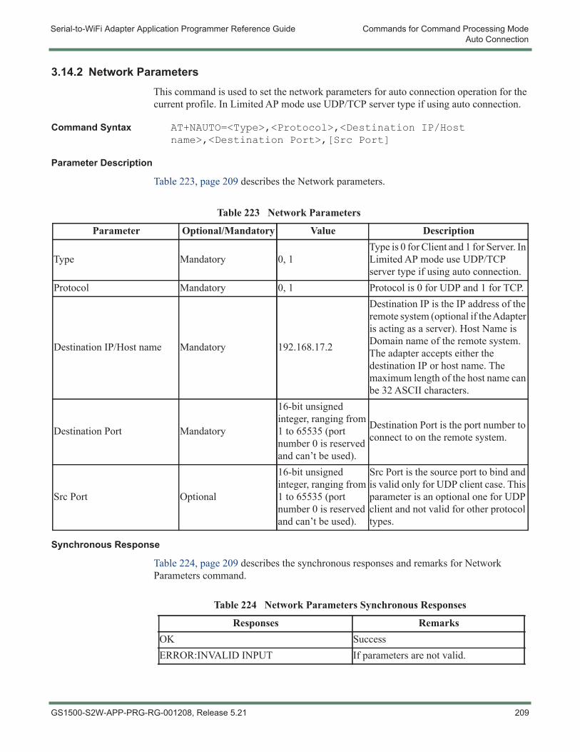
Serial-to-WiFi Adapter Application Programmer Reference Guide Commands for Command Processing ModeAuto Connection
3.14.2 Network ParametersThis command is used to set the network parameters for auto connection operation for the current profile. In Limited AP mode use UDP/TCP server type if using auto connection.
Command Syntax AT+NAUTO=<Type>,<Protocol>,<Destination IP/Host name>,<Destination Port>,[Src Port]
Parameter Description
Table 223, page 209 describes the Network parameters.
Synchronous Response
Table 224, page 209 describes the synchronous responses and remarks for Network Parameters command.
Table 223 Network Parameters
Parameter Optional/Mandatory Value Description
Type Mandatory 0, 1Type is 0 for Client and 1 for Server. In Limited AP mode use UDP/TCP server type if using auto connection.
Protocol Mandatory 0, 1 Protocol is 0 for UDP and 1 for TCP.
Destination IP/Host name Mandatory 192.168.17.2
Destination IP is the IP address of the remote system (optional if the Adapter is acting as a server). Host Name is Domain name of the remote system. The adapter accepts either the destination IP or host name. The maximum length of the host name can be 32 ASCII characters.
Destination Port Mandatory
16-bit unsigned integer, ranging from 1 to 65535 (port number 0 is reserved and can’t be used).
Destination Port is the port number to connect to on the remote system.
Src Port Optional
16-bit unsigned integer, ranging from 1 to 65535 (port number 0 is reserved and can’t be used).
Src Port is the source port to bind and is valid only for UDP client case. This parameter is an optional one for UDP client and not valid for other protocol types.
Table 224 Network Parameters Synchronous Responses
Responses RemarksOK SuccessERROR:INVALID INPUT If parameters are not valid.
GS1500-S2W-APP-PRG-RG-001208, Release 5.21 209
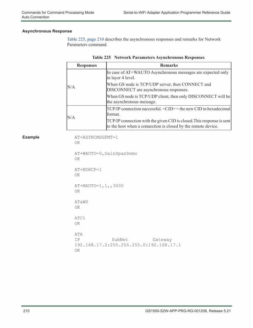
Commands for Command Processing Mode Serial-to-WiFi Adapter Application Programmer Reference GuideAuto Connection
Asynchronous Response
Table 225, page 210 describes the asynchronous responses and remarks for Network Parameters command.
Example AT+ASYNCMSGFMT=1OK
AT+WAUTO=0,GainSpanDemoOK
AT+NDHCP=1OK
AT+NAUTO=1,1,,3000OK
AT&W0OK
ATC1OK
ATAIP SubNet Gateway192.168.17.2:255.255.255.0:192.168.17.1OK
Table 225 Network Parameters Asynchronous Responses
Responses Remarks
N/A
In case of AT+WAUTO Asynchronous messages are expected only in layer 4 level.When GS node is TCP/UDP server, then CONNECT and DISCONNECT are asynchronous responses.When GS node is TCP/UDP client, then only DISCONNECT will be the asynchronous message.
N/A
TCP/IP connection successful. <CID> = the new CID in hexadecimal format.TCP/IP connection with the given CID is closed.This response is sent to the host when a connection is closed by the remote device.
210 GS1500-S2W-APP-PRG-RG-001208, Release 5.21
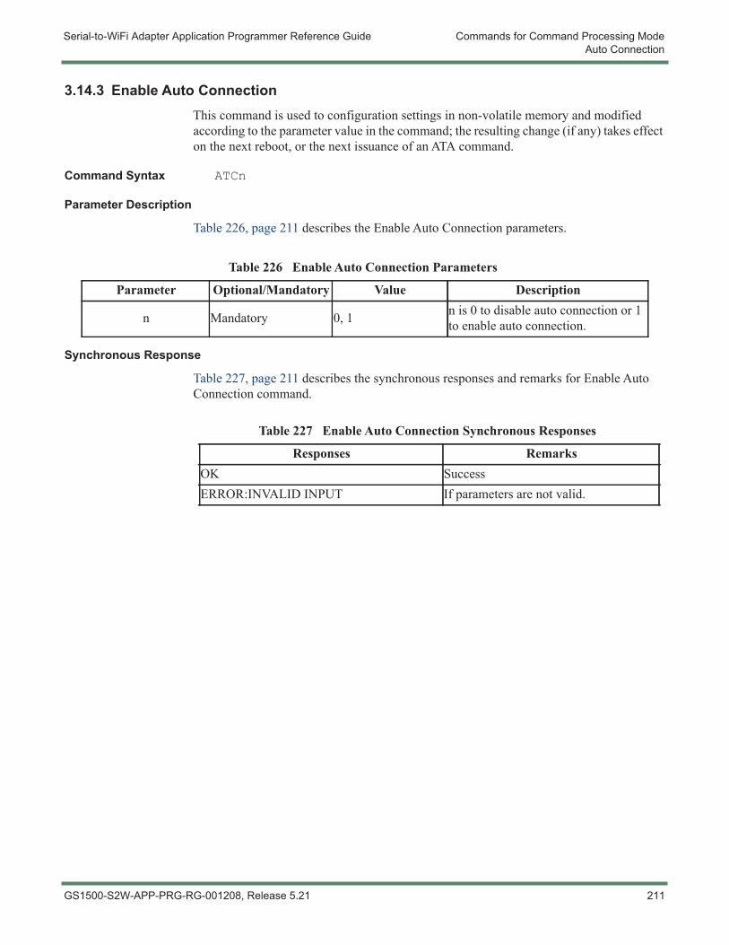
Serial-to-WiFi Adapter Application Programmer Reference Guide Commands for Command Processing ModeAuto Connection
3.14.3 Enable Auto ConnectionThis command is used to configuration settings in non-volatile memory and modified according to the parameter value in the command; the resulting change (if any) takes effect on the next reboot, or the next issuance of an ATA command.
Command Syntax ATCn
Parameter Description
Table 226, page 211 describes the Enable Auto Connection parameters.
Synchronous Response
Table 227, page 211 describes the synchronous responses and remarks for Enable Auto Connection command.
Table 226 Enable Auto Connection Parameters
Parameter Optional/Mandatory Value Description
n Mandatory 0, 1 n is 0 to disable auto connection or 1 to enable auto connection.
Table 227 Enable Auto Connection Synchronous Responses
Responses RemarksOK SuccessERROR:INVALID INPUT If parameters are not valid.
GS1500-S2W-APP-PRG-RG-001208, Release 5.21 211
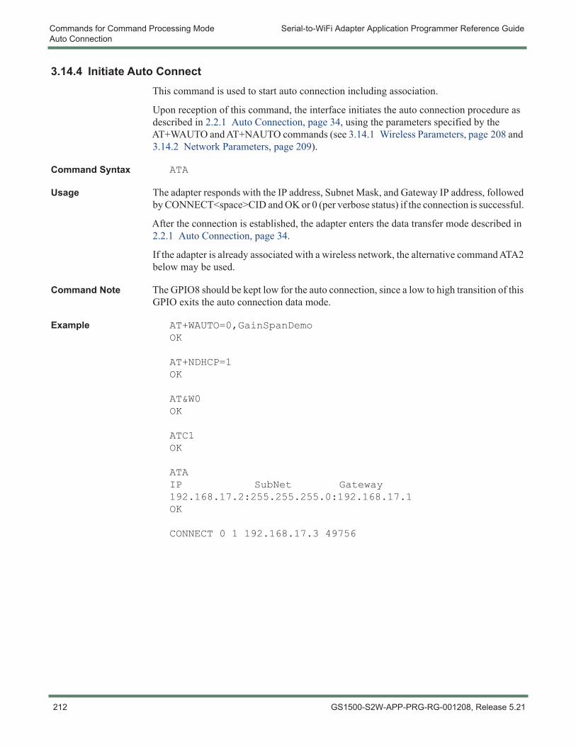
Commands for Command Processing Mode Serial-to-WiFi Adapter Application Programmer Reference GuideAuto Connection
3.14.4 Initiate Auto ConnectThis command is used to start auto connection including association.
Upon reception of this command, the interface initiates the auto connection procedure as described in 2.2.1 Auto Connection, page 34, using the parameters specified by the AT+WAUTO and AT+NAUTO commands (see 3.14.1 Wireless Parameters, page 208 and 3.14.2 Network Parameters, page 209).
Command Syntax ATA
Usage The adapter responds with the IP address, Subnet Mask, and Gateway IP address, followed by CONNECT<space>CID and OK or 0 (per verbose status) if the connection is successful.
After the connection is established, the adapter enters the data transfer mode described in 2.2.1 Auto Connection, page 34.
If the adapter is already associated with a wireless network, the alternative command ATA2 below may be used.
Command Note The GPIO8 should be kept low for the auto connection, since a low to high transition of this GPIO exits the auto connection data mode.
Example AT+WAUTO=0,GainSpanDemoOK
AT+NDHCP=1OK
AT&W0OK
ATC1OK
ATAIP SubNet Gateway192.168.17.2:255.255.255.0:192.168.17.1OK
CONNECT 0 1 192.168.17.3 49756
212 GS1500-S2W-APP-PRG-RG-001208, Release 5.21
Serial-to-WiFi Adapter Application Programmer Reference Guide Commands for Command Processing ModeAuto Connection
3.14.5 Exit from Auto Connect Data ModeIn auto connect mode the adapter opens a serial data pipe to pass the serial data from/to the host MCU to/from the remote machine. In this mode all serial input treated as data. To enable the command mode without breaks the connection the adapter provides the following mechanisms:
1. +++ and wait for 1 second. After this the adapter exit the data mode and it can able to accept the AT commands to change the configuration.
2. Make the GPIO8 high. With this also the adapter exit the data mode and it can able to accept the AT commands to change the configuration.
3.14.6 Return to Auto Connect ModeThe command is used to return to auto connect mode.
Command Syntax ATO
Usage If the interface receives this command after it has exited the auto connect mode with +++ or GPIO8 high, it shall return to auto connect mode. If the connection no longer exists, the interface attempts to reestablish the previous connection, and returns to data mode if the reconnection is successful. If the Adapter was not previously connected when this command is received, it returns an error.
Command Response This command returns standard command response or ERROR, if the operation fails.
GS1500-S2W-APP-PRG-RG-001208, Release 5.21 213
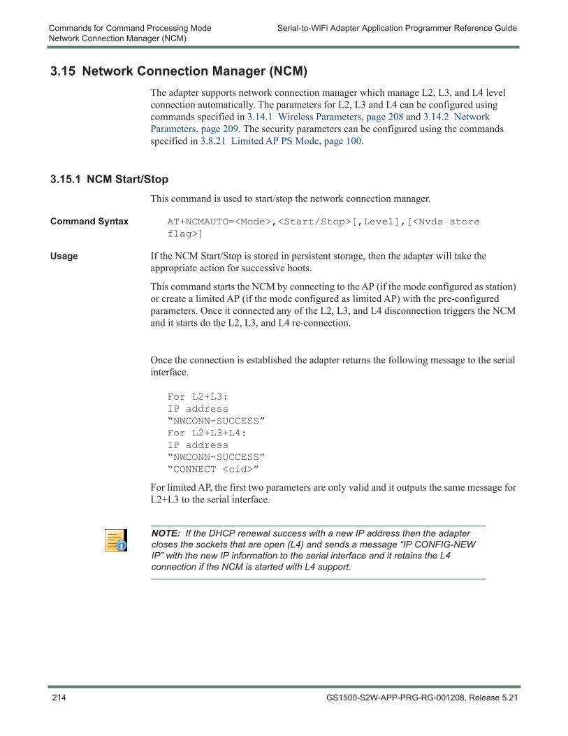
Commands for Command Processing Mode Serial-to-WiFi Adapter Application Programmer Reference GuideNetwork Connection Manager (NCM)
3.15 Network Connection Manager (NCM)The adapter supports network connection manager which manage L2, L3, and L4 level connection automatically. The parameters for L2, L3 and L4 can be configured using commands specified in 3.14.1 Wireless Parameters, page 208 and 3.14.2 Network Parameters, page 209. The security parameters can be configured using the commands specified in 3.8.21 Limited AP PS Mode, page 100.
3.15.1 NCM Start/StopThis command is used to start/stop the network connection manager.
Command Syntax AT+NCMAUTO=<Mode>,<Start/Stop>[,Level],[<Nvds store flag>]
Usage If the NCM Start/Stop is stored in persistent storage, then the adapter will take the appropriate action for successive boots.
This command starts the NCM by connecting to the AP (if the mode configured as station) or create a limited AP (if the mode configured as limited AP) with the pre-configured parameters. Once it connected any of the L2, L3, and L4 disconnection triggers the NCM and it starts do the L2, L3, and L4 re-connection.
Once the connection is established the adapter returns the following message to the serial interface.
For L2+L3:IP address“NWCONN-SUCCESS”For L2+L3+L4:IP address “NWCONN-SUCCESS”“CONNECT <cid>”
For limited AP, the first two parameters are only valid and it outputs the same message for L2+L3 to the serial interface.
NOTE: If the DHCP renewal success with a new IP address then the adapter closes the sockets that are open (L4) and sends a message “IP CONFIG-NEW IP” with the new IP information to the serial interface and it retains the L4 connection if the NCM is started with L4 support.
214 GS1500-S2W-APP-PRG-RG-001208, Release 5.21
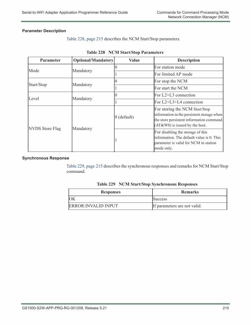
Serial-to-WiFi Adapter Application Programmer Reference Guide Commands for Command Processing ModeNetwork Connection Manager (NCM)
Parameter Description
Table 228, page 215 describes the NCM Start/Stop parameters.
Synchronous Response
Table 229, page 215 describes the synchronous responses and remarks for NCM Start/Stop command.
Table 228 NCM Start/Stop Parameters
Parameter Optional/Mandatory Value Description
Mode Mandatory0 For station mode1 For limited AP mode
Start/Stop Mandatory0 For stop the NCM1 For start the NCM
Level Mandatory0 For L2+L3 connection1 For L2+L3+L4 connection
NVDS Store Flag Mandatory
0 (default)
For storing the NCM Start/Stop information in the persistent storage when the store persistent information command (AT&W0) is issued by the host.
1
For disabling the storage of this information. The default value is 0. This parameter is valid for NCM in station mode only.
Table 229 NCM Start/Stop Synchronous Responses
Responses RemarksOK SuccessERROR:INVALID INPUT If parameters are not valid.
GS1500-S2W-APP-PRG-RG-001208, Release 5.21 215
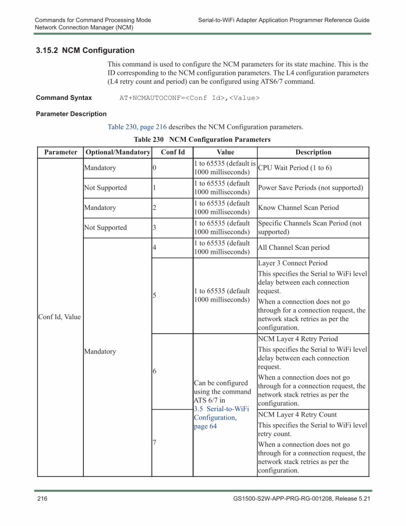
Commands for Command Processing Mode Serial-to-WiFi Adapter Application Programmer Reference GuideNetwork Connection Manager (NCM)
3.15.2 NCM ConfigurationThis command is used to configure the NCM parameters for its state machine. This is the ID corresponding to the NCM configuration parameters. The L4 configuration parameters (L4 retry count and period) can be configured using ATS6/7 command.
Command Syntax AT+NCMAUTOCONF=<Conf Id>,<Value>
Parameter Description
Table 230, page 216 describes the NCM Configuration parameters.
Table 230 NCM Configuration Parameters
Parameter Optional/Mandatory Conf Id Value Description
Conf Id, Value
Mandatory 0 1 to 65535 (default is 1000 milliseconds) CPU Wait Period (1 to 6)
Not Supported 1 1 to 65535 (default 1000 milliseconds) Power Save Periods (not supported)
Mandatory 2 1 to 65535 (default 1000 milliseconds) Know Channel Scan Period
Not Supported 3 1 to 65535 (default 1000 milliseconds)
Specific Channels Scan Period (not supported)
Mandatory
4 1 to 65535 (default 1000 milliseconds) All Channel Scan period
5 1 to 65535 (default 1000 milliseconds)
Layer 3 Connect PeriodThis specifies the Serial to WiFi level delay between each connection request.When a connection does not go through for a connection request, the network stack retries as per the configuration.
6Can be configured using the command ATS 6/7 in 3.5 Serial-to-WiFi Configuration, page 64
NCM Layer 4 Retry PeriodThis specifies the Serial to WiFi level delay between each connection request.When a connection does not go through for a connection request, the network stack retries as per the configuration.
7
NCM Layer 4 Retry CountThis specifies the Serial to WiFi level retry count.When a connection does not go through for a connection request, the network stack retries as per the configuration.
216 GS1500-S2W-APP-PRG-RG-001208, Release 5.21
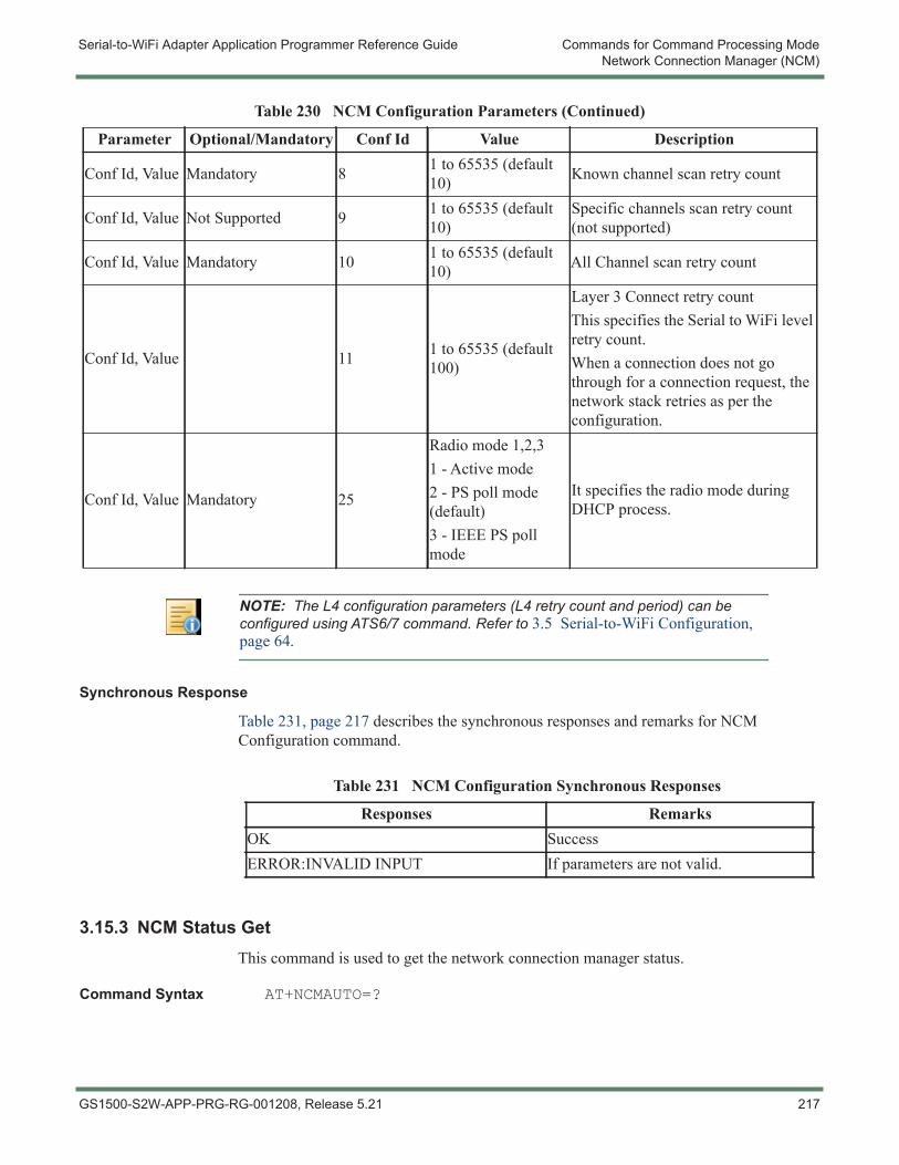
Serial-to-WiFi Adapter Application Programmer Reference Guide Commands for Command Processing ModeNetwork Connection Manager (NCM)
Synchronous Response
Table 231, page 217 describes the synchronous responses and remarks for NCM Configuration command.
3.15.3 NCM Status GetThis command is used to get the network connection manager status.
Command Syntax AT+NCMAUTO=?
Conf Id, Value Mandatory 8 1 to 65535 (default 10) Known channel scan retry count
Conf Id, Value Not Supported 9 1 to 65535 (default 10)
Specific channels scan retry count (not supported)
Conf Id, Value Mandatory 10 1 to 65535 (default 10) All Channel scan retry count
Conf Id, Value 11 1 to 65535 (default 100)
Layer 3 Connect retry count This specifies the Serial to WiFi level retry count.When a connection does not go through for a connection request, the network stack retries as per the configuration.
Conf Id, Value Mandatory 25
Radio mode 1,2,31 - Active mode2 - PS poll mode (default)3 - IEEE PS poll mode
It specifies the radio mode during DHCP process.
Table 230 NCM Configuration Parameters (Continued)
Parameter Optional/Mandatory Conf Id Value Description
NOTE: The L4 configuration parameters (L4 retry count and period) can be configured using ATS6/7 command. Refer to 3.5 Serial-to-WiFi Configuration, page 64.
Table 231 NCM Configuration Synchronous Responses
Responses RemarksOK SuccessERROR:INVALID INPUT If parameters are not valid.
GS1500-S2W-APP-PRG-RG-001208, Release 5.21 217
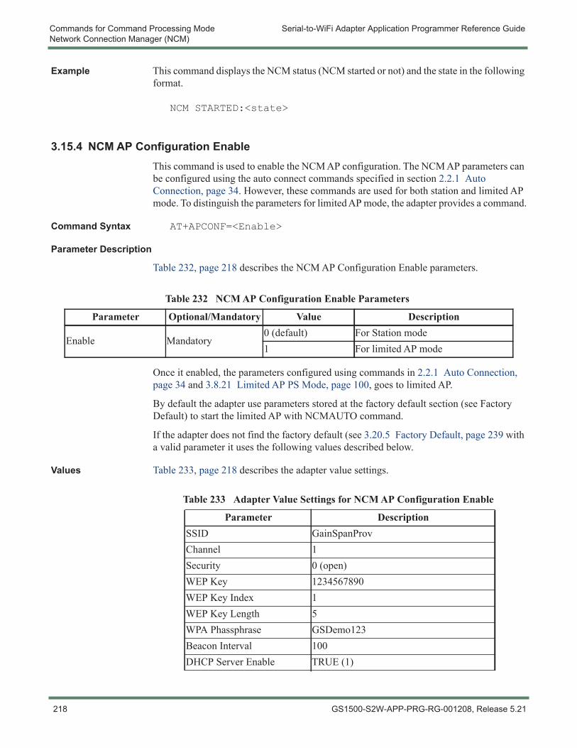
Commands for Command Processing Mode Serial-to-WiFi Adapter Application Programmer Reference GuideNetwork Connection Manager (NCM)
Example This command displays the NCM status (NCM started or not) and the state in the following format.
NCM STARTED:<state>
3.15.4 NCM AP Configuration EnableThis command is used to enable the NCM AP configuration. The NCM AP parameters can be configured using the auto connect commands specified in section 2.2.1 Auto Connection, page 34. However, these commands are used for both station and limited AP mode. To distinguish the parameters for limited AP mode, the adapter provides a command.
Command Syntax AT+APCONF=<Enable>
Parameter Description
Table 232, page 218 describes the NCM AP Configuration Enable parameters.
Once it enabled, the parameters configured using commands in 2.2.1 Auto Connection, page 34 and 3.8.21 Limited AP PS Mode, page 100, goes to limited AP.
By default the adapter use parameters stored at the factory default section (see Factory Default) to start the limited AP with NCMAUTO command.
If the adapter does not find the factory default (see 3.20.5 Factory Default, page 239 with a valid parameter it uses the following values described below.
Values Table 233, page 218 describes the adapter value settings.
Table 232 NCM AP Configuration Enable Parameters
Parameter Optional/Mandatory Value Description
Enable Mandatory0 (default) For Station mode1 For limited AP mode
Table 233 Adapter Value Settings for NCM AP Configuration Enable
Parameter DescriptionSSID GainSpanProvChannel 1Security 0 (open)WEP Key 1234567890WEP Key Index 1WEP Key Length 5WPA Phassphrase GSDemo123Beacon Interval 100DHCP Server Enable TRUE (1)
218 GS1500-S2W-APP-PRG-RG-001208, Release 5.21
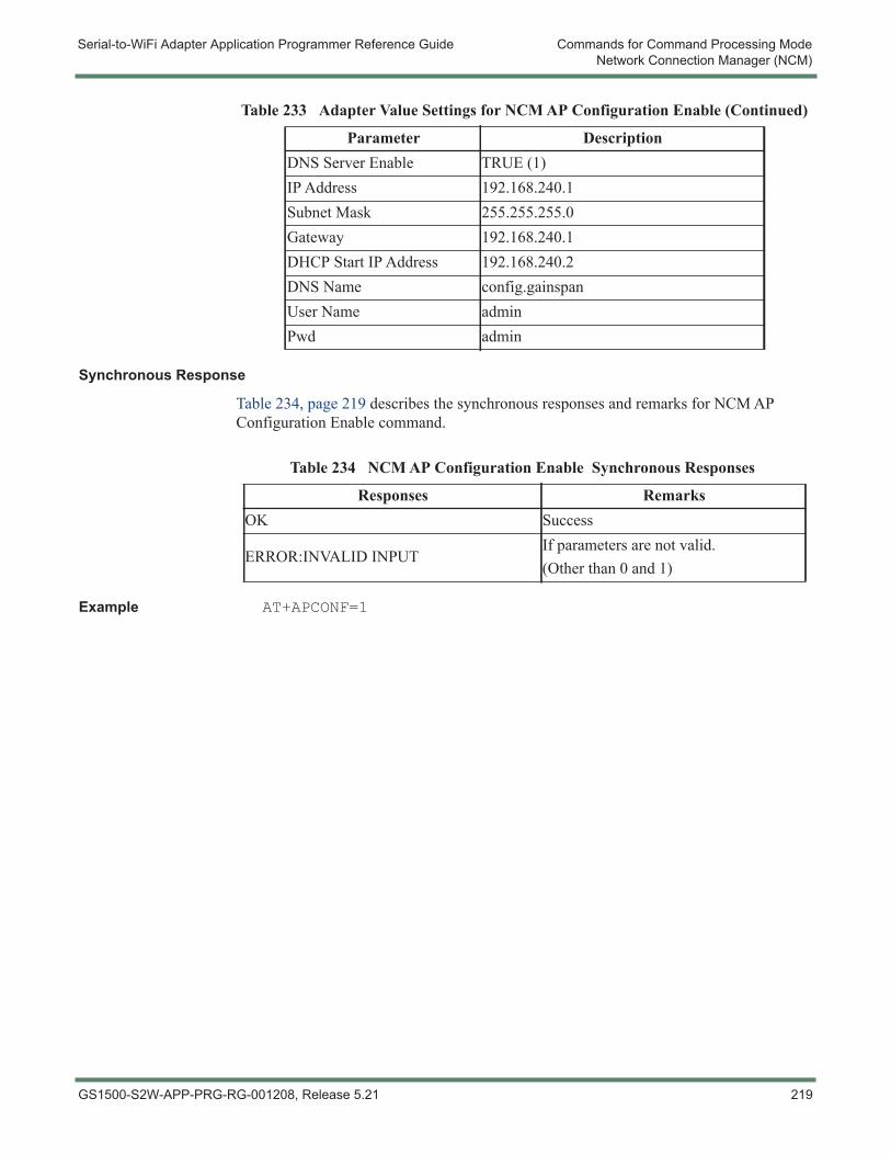
Serial-to-WiFi Adapter Application Programmer Reference Guide Commands for Command Processing ModeNetwork Connection Manager (NCM)
Synchronous Response
Table 234, page 219 describes the synchronous responses and remarks for NCM AP Configuration Enable command.
Example AT+APCONF=1
DNS Server Enable TRUE (1)IP Address 192.168.240.1Subnet Mask 255.255.255.0Gateway 192.168.240.1DHCP Start IP Address 192.168.240.2DNS Name config.gainspanUser Name adminPwd admin
Table 233 Adapter Value Settings for NCM AP Configuration Enable (Continued)
Parameter Description
Table 234 NCM AP Configuration Enable Synchronous Responses
Responses RemarksOK Success
ERROR:INVALID INPUTIf parameters are not valid.(Other than 0 and 1)
GS1500-S2W-APP-PRG-RG-001208, Release 5.21 219
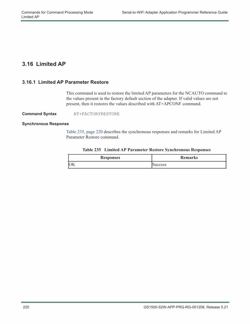
Commands for Command Processing Mode Serial-to-WiFi Adapter Application Programmer Reference GuideLimited AP
3.16 Limited AP
3.16.1 Limited AP Parameter Restore
This command is used to restore the limited AP parameters for the NCAUTO command to the values present in the factory default section of the adapter. If valid values are not present, then it restores the values described with AT+APCONF command.
Command Syntax AT+FACTORYRESTORE
Synchronous Response
Table 235, page 220 describes the synchronous responses and remarks for Limited AP Parameter Restore command.
Table 235 Limited AP Parameter Restore Synchronous Responses
Responses RemarksOK Success
220 GS1500-S2W-APP-PRG-RG-001208, Release 5.21
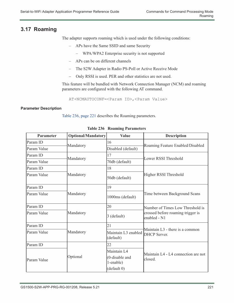
Serial-to-WiFi Adapter Application Programmer Reference Guide Commands for Command Processing ModeRoaming
3.17 RoamingThe adapter supports roaming which is used under the following conditions:
– APs have the Same SSID and same Security
– WPA/WPA2 Enterprise security is not supported
– APs can be on different channels
– The S2W Adapter in Radio PS-Poll or Active Receive Mode
– Only RSSI is used. PER and other statistics are not used.
This feature will be bundled with Network Connection Manager (NCM) and roaming parameters are configured with the following AT command.
AT+NCMAUTOCONF=<Param ID>,<Param Value>
Parameter Description
Table 236, page 221 describes the Roaming parameters.
Table 236 Roaming Parameters
Parameter Optional/Mandatory Value DescriptionParam ID
Mandatory16
Roaming Feature Enabled/DisabledParam Value Disabled (default)Param ID
Mandatory17
Lower RSSI ThresholdParam Value 70db (default)Param ID
Mandatory18
Higher RSSI ThresholdParam Value50db (default)
Param IDMandatory
19Time between Background ScansParam Value
1000ms (default)
Param IDMandatory
20 Number of Times Low Threshold is crossed before roaming trigger is enabled - N1
Param Value3 (default)
Param IDMandatory
21Maintain L3 - there is a common DHCP Server.Param Value Maintain L3 enabled
(default)
Param ID
Optional
22
Maintain L4 - L4 connection are not closed.Param Value
Maintain L4(0-disable and 1-enable)(default 0)
GS1500-S2W-APP-PRG-RG-001208, Release 5.21 221
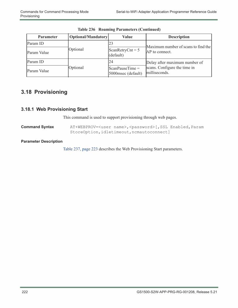
Commands for Command Processing Mode Serial-to-WiFi Adapter Application Programmer Reference GuideProvisioning
3.18 Provisioning
3.18.1 Web Provisioning StartThis command is used to support provisioning through web pages.
Command Syntax AT+WEBPROV=<user name>,<password>[,SSL Enabled,Param StoreOption,idletimeout,ncmautoconnect]
Parameter Description
Table 237, page 223 describes the Web Provisioning Start parameters.
Param IDOptional
23Maximum number of scans to find the AP to connect.Param Value ScanRetryCnt = 5
(default)Param ID
Optional24 Delay after maximum number of
scans. Configure the time in milliseconds.Param Value ScanPauseTime =
5000msec (default)
Table 236 Roaming Parameters (Continued)
Parameter Optional/Mandatory Value Description
222 GS1500-S2W-APP-PRG-RG-001208, Release 5.21
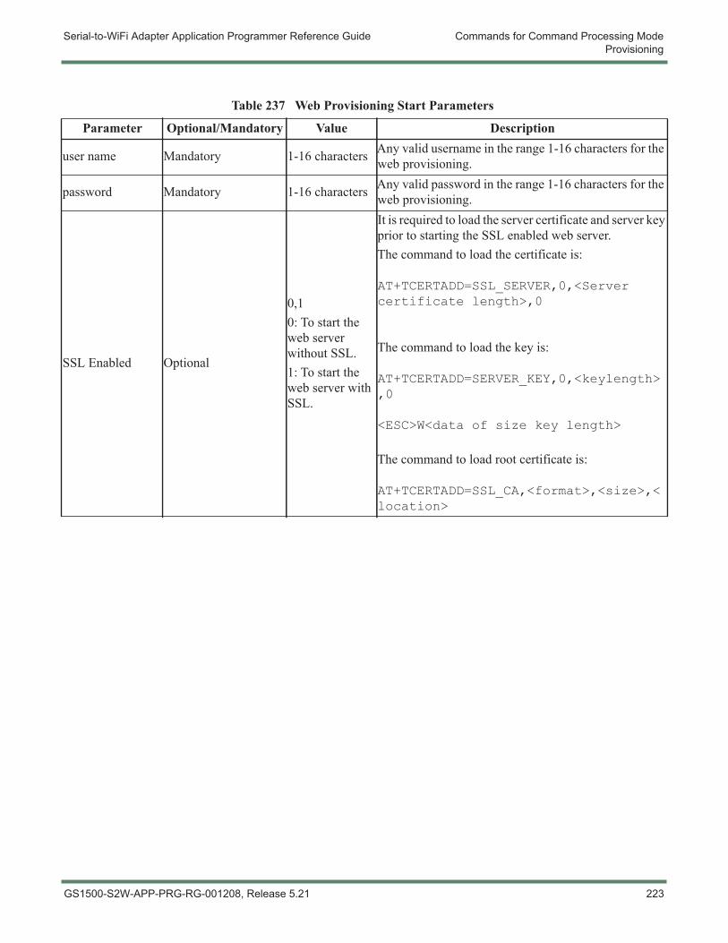
Serial-to-WiFi Adapter Application Programmer Reference Guide Commands for Command Processing ModeProvisioning
Table 237 Web Provisioning Start Parameters
Parameter Optional/Mandatory Value Description
user name Mandatory 1-16 characters Any valid username in the range 1-16 characters for the web provisioning.
password Mandatory 1-16 characters Any valid password in the range 1-16 characters for the web provisioning.
SSL Enabled Optional
0,10: To start the web server without SSL.1: To start the web server with SSL.
It is required to load the server certificate and server key prior to starting the SSL enabled web server.The command to load the certificate is:
AT+TCERTADD=SSL_SERVER,0,<Server certificate length>,0
The command to load the key is:
AT+TCERTADD=SERVER_KEY,0,<keylength>,0
<ESC>W<data of size key length>
The command to load root certificate is:
AT+TCERTADD=SSL_CA,<format>,<size>,<location>
GS1500-S2W-APP-PRG-RG-001208, Release 5.21 223
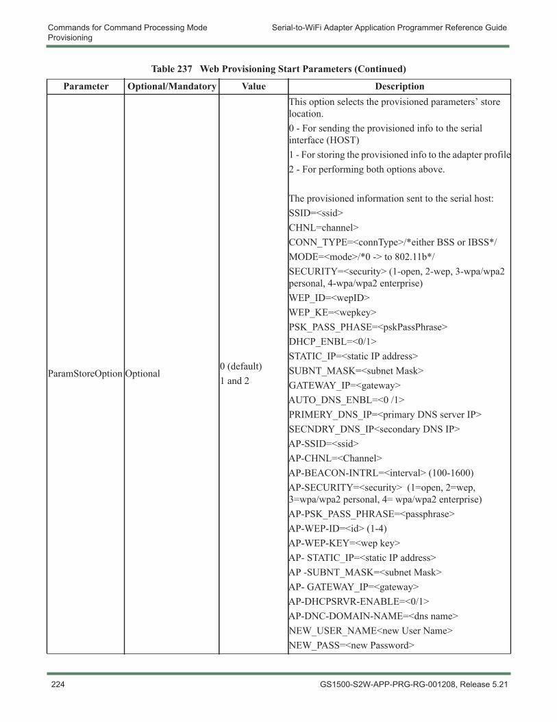
Commands for Command Processing Mode Serial-to-WiFi Adapter Application Programmer Reference GuideProvisioning
ParamStoreOption Optional0 (default)1 and 2
This option selects the provisioned parameters’ store location.0 - For sending the provisioned info to the serial interface (HOST)1 - For storing the provisioned info to the adapter profile2 - For performing both options above.
The provisioned information sent to the serial host:SSID=<ssid>CHNL=channel>CONN_TYPE=<connType>/*either BSS or IBSS*/MODE=<mode>/*0 -> to 802.11b*/SECURITY=<security> (1-open, 2-wep, 3-wpa/wpa2 personal, 4-wpa/wpa2 enterprise)WEP_ID=<wepID>WEP_KE=<wepkey>PSK_PASS_PHASE=<pskPassPhrase>DHCP_ENBL=<0/1>STATIC_IP=<static IP address>SUBNT_MASK=<subnet Mask>GATEWAY_IP=<gateway>AUTO_DNS_ENBL=<0 /1>PRIMERY_DNS_IP=<primary DNS server IP>SECNDRY_DNS_IP<secondary DNS IP>AP-SSID=<ssid>AP-CHNL=<Channel>AP-BEACON-INTRL=<interval> (100-1600)AP-SECURITY=<security> (1=open, 2=wep, 3=wpa/wpa2 personal, 4= wpa/wpa2 enterprise)AP-PSK_PASS_PHRASE=<passphrase>AP-WEP-ID=<id> (1-4)AP-WEP-KEY=<wep key>AP- STATIC_IP=<static IP address>AP -SUBNT_MASK=<subnet Mask>AP- GATEWAY_IP=<gateway>AP-DHCPSRVR-ENABLE=<0/1>AP-DNC-DOMAIN-NAME=<dns name>NEW_USER_NAME<new User Name>NEW_PASS=<new Password>
Table 237 Web Provisioning Start Parameters (Continued)
Parameter Optional/Mandatory Value Description
224 GS1500-S2W-APP-PRG-RG-001208, Release 5.21
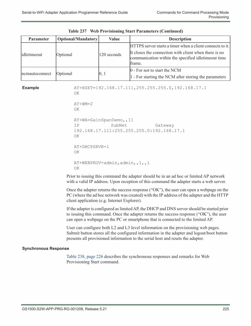
Serial-to-WiFi Adapter Application Programmer Reference Guide Commands for Command Processing ModeProvisioning
Example AT+NSET=192.168.17.111,255.255.255.0,192.168.17.1OK
AT+WM=2OK
AT+WA=GainSpanDemo,,11IP SubNet Gateway192.168.17.111:255.255.255.0:192.168.17.1OK
AT+DHCPSRVR=1OK
AT+WEBPROV=admin,admin,,1,,1OK
Prior to issuing this command the adapter should be in an ad hoc or limited AP network with a valid IP address. Upon reception of this command the adapter starts a web server.
Once the adapter returns the success response (“OK”), the user can open a webpage on the PC (where the ad hoc network was created) with the IP address of the adapter and the HTTP client application (e.g. Internet Explorer).
If the adapter is configured as limited AP, the DHCP and DNS server should be started prior to issuing this command. Once the adapter returns the success response (“OK”), the user can open a webpage on the PC or smartphone that is connected to the limited AP.
User can configure both L2 and L3 level information on the provisioning web pages. Submit button stores all the configured information in the adapter and logout/boot button presents all provisioned information to the serial host and resets the adapter.
Synchronous Response
Table 238, page 226 describes the synchronous responses and remarks for Web Provisioning Start command.
idletimeout Optional 120 seconds
HTTPS server starts a timer when a client connects to it. It closes the connection with client when there is no communication within the specified idletimeout time frame.
ncmautoconnect Optional 0, 10 - For not to start the NCM1 - For starting the NCM after storing the parameters
Table 237 Web Provisioning Start Parameters (Continued)
Parameter Optional/Mandatory Value Description
GS1500-S2W-APP-PRG-RG-001208, Release 5.21 225
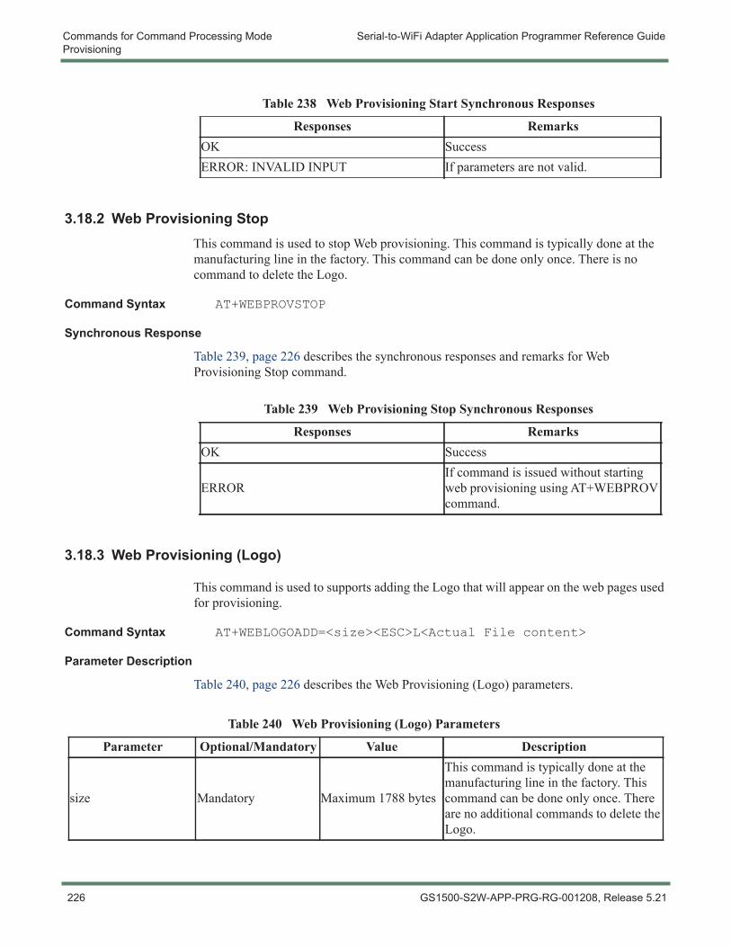
Commands for Command Processing Mode Serial-to-WiFi Adapter Application Programmer Reference GuideProvisioning
3.18.2 Web Provisioning StopThis command is used to stop Web provisioning. This command is typically done at the manufacturing line in the factory. This command can be done only once. There is no command to delete the Logo.
Command Syntax AT+WEBPROVSTOP
Synchronous Response
Table 239, page 226 describes the synchronous responses and remarks for Web Provisioning Stop command.
3.18.3 Web Provisioning (Logo)
This command is used to supports adding the Logo that will appear on the web pages used for provisioning.
Command Syntax AT+WEBLOGOADD=<size><ESC>L<Actual File content>
Parameter Description
Table 240, page 226 describes the Web Provisioning (Logo) parameters.
Table 238 Web Provisioning Start Synchronous Responses
Responses RemarksOK SuccessERROR: INVALID INPUT If parameters are not valid.
Table 239 Web Provisioning Stop Synchronous Responses
Responses RemarksOK Success
ERRORIf command is issued without starting web provisioning using AT+WEBPROV command.
Table 240 Web Provisioning (Logo) Parameters
Parameter Optional/Mandatory Value Description
size Mandatory Maximum 1788 bytes
This command is typically done at the manufacturing line in the factory. This command can be done only once. There are no additional commands to delete the Logo.
226 GS1500-S2W-APP-PRG-RG-001208, Release 5.21
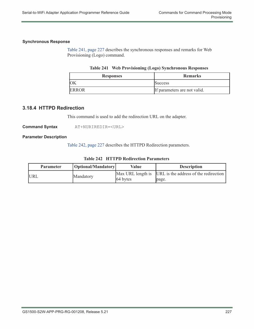
Serial-to-WiFi Adapter Application Programmer Reference Guide Commands for Command Processing ModeProvisioning
Synchronous Response
Table 241, page 227 describes the synchronous responses and remarks for Web Provisioning (Logo) command.
3.18.4 HTTPD RedirectionThis command is used to add the redirection URL on the adapter.
Command Syntax AT+NURIREDIR=<URL>
Parameter Description
Table 242, page 227 describes the HTTPD Redirection parameters.
Table 241 Web Provisioning (Logo) Synchronous Responses
Responses RemarksOK SuccessERROR If parameters are not valid.
Table 242 HTTPD Redirection Parameters
Parameter Optional/Mandatory Value Description
URL Mandatory Max URL length is 64 bytes
URL is the address of the redirection page.
GS1500-S2W-APP-PRG-RG-001208, Release 5.21 227
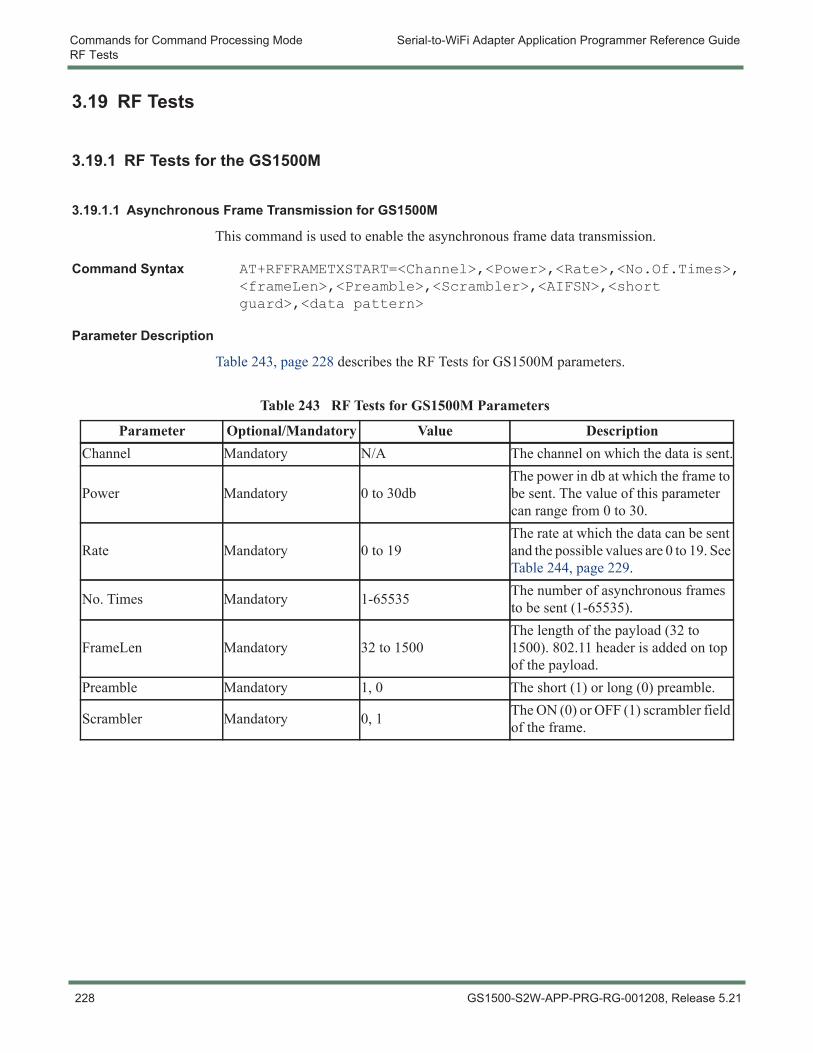
Commands for Command Processing Mode Serial-to-WiFi Adapter Application Programmer Reference GuideRF Tests
3.19 RF Tests
3.19.1 RF Tests for the GS1500M
3.19.1.1 Asynchronous Frame Transmission for GS1500M
This command is used to enable the asynchronous frame data transmission.
Command Syntax AT+RFFRAMETXSTART=<Channel>,<Power>,<Rate>,<No.Of.Times>,<frameLen>,<Preamble>,<Scrambler>,<AIFSN>,<short guard>,<data pattern>
Parameter Description
Table 243, page 228 describes the RF Tests for GS1500M parameters.
Table 243 RF Tests for GS1500M Parameters
Parameter Optional/Mandatory Value DescriptionChannel Mandatory N/A The channel on which the data is sent.
Power Mandatory 0 to 30dbThe power in db at which the frame to be sent. The value of this parameter can range from 0 to 30.
Rate Mandatory 0 to 19The rate at which the data can be sent and the possible values are 0 to 19. See Table 244, page 229.
No. Times Mandatory 1-65535 The number of asynchronous frames to be sent (1-65535).
FrameLen Mandatory 32 to 1500The length of the payload (32 to 1500). 802.11 header is added on top of the payload.
Preamble Mandatory 1, 0 The short (1) or long (0) preamble.
Scrambler Mandatory 0, 1 The ON (0) or OFF (1) scrambler field of the frame.
228 GS1500-S2W-APP-PRG-RG-001208, Release 5.21
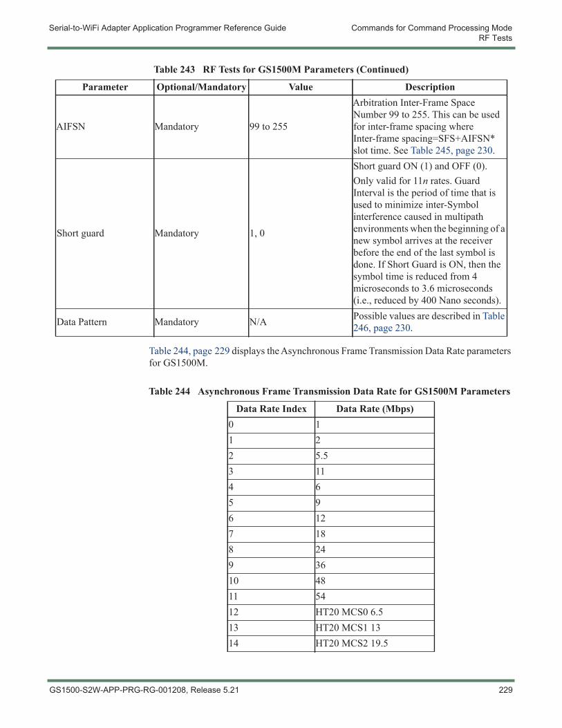
Serial-to-WiFi Adapter Application Programmer Reference Guide Commands for Command Processing ModeRF Tests
Table 244, page 229 displays the Asynchronous Frame Transmission Data Rate parameters for GS1500M.
AIFSN Mandatory 99 to 255
Arbitration Inter-Frame Space Number 99 to 255. This can be used for inter-frame spacing where Inter-frame spacing=SFS+AIFSN* slot time. See Table 245, page 230.
Short guard Mandatory 1, 0
Short guard ON (1) and OFF (0).Only valid for 11n rates. Guard Interval is the period of time that is used to minimize inter-Symbol interference caused in multipath environments when the beginning of a new symbol arrives at the receiver before the end of the last symbol is done. If Short Guard is ON, then the symbol time is reduced from 4 microseconds to 3.6 microseconds (i.e., reduced by 400 Nano seconds).
Data Pattern Mandatory N/A Possible values are described in Table 246, page 230.
Table 243 RF Tests for GS1500M Parameters (Continued)
Parameter Optional/Mandatory Value Description
Table 244 Asynchronous Frame Transmission Data Rate for GS1500M Parameters
Data Rate Index Data Rate (Mbps)0 11 22 5.53 114 65 96 127 188 249 3610 4811 5412 HT20 MCS0 6.513 HT20 MCS1 1314 HT20 MCS2 19.5
GS1500-S2W-APP-PRG-RG-001208, Release 5.21 229
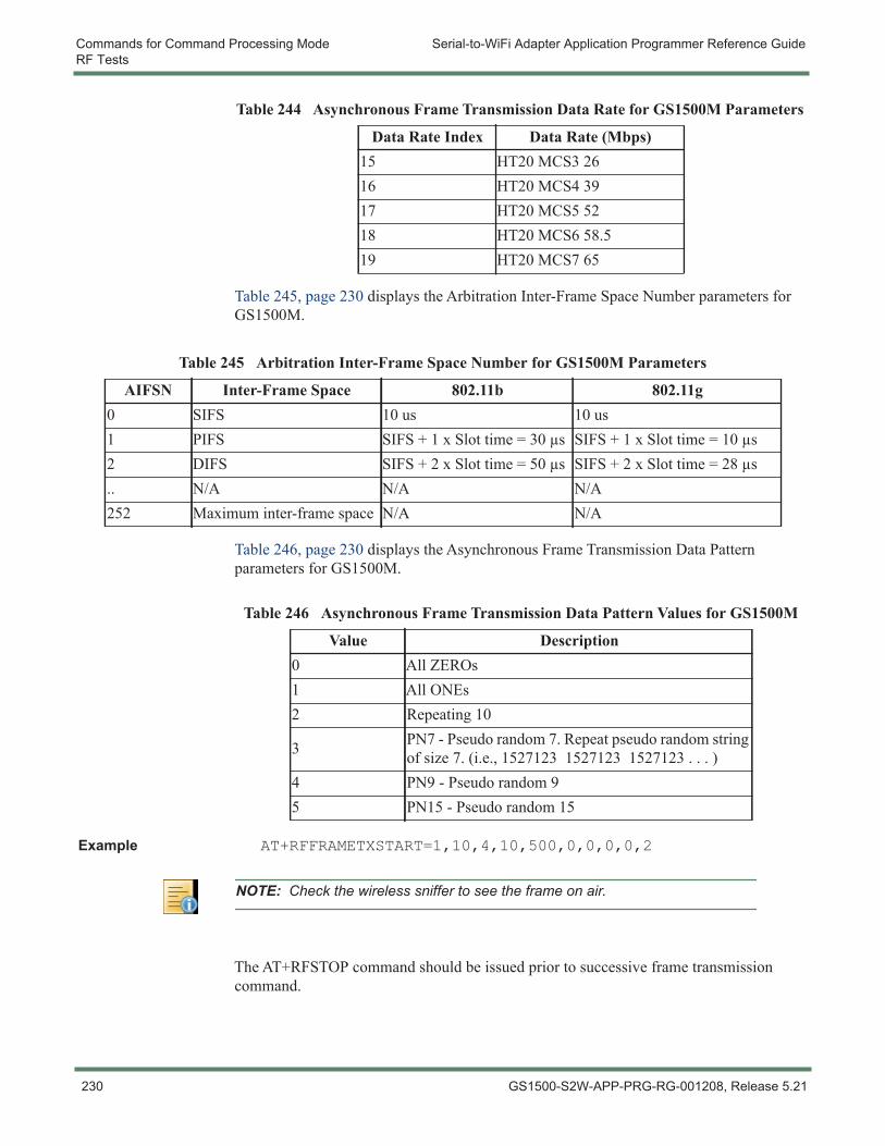
Commands for Command Processing Mode Serial-to-WiFi Adapter Application Programmer Reference GuideRF Tests
Table 245, page 230 displays the Arbitration Inter-Frame Space Number parameters for GS1500M.
Table 246, page 230 displays the Asynchronous Frame Transmission Data Pattern parameters for GS1500M.
Example AT+RFFRAMETXSTART=1,10,4,10,500,0,0,0,0,2
The AT+RFSTOP command should be issued prior to successive frame transmission command.
15 HT20 MCS3 2616 HT20 MCS4 3917 HT20 MCS5 5218 HT20 MCS6 58.519 HT20 MCS7 65
Table 244 Asynchronous Frame Transmission Data Rate for GS1500M Parameters
Data Rate Index Data Rate (Mbps)
Table 245 Arbitration Inter-Frame Space Number for GS1500M Parameters
AIFSN Inter-Frame Space 802.11b 802.11g0 SIFS 10 us 10 us1 PIFS SIFS + 1 x Slot time = 30 μs SIFS + 1 x Slot time = 10 μs2 DIFS SIFS + 2 x Slot time = 50 μs SIFS + 2 x Slot time = 28 μs.. N/A N/A N/A252 Maximum inter-frame space N/A N/A
Table 246 Asynchronous Frame Transmission Data Pattern Values for GS1500M
Value Description0 All ZEROs1 All ONEs2 Repeating 10
3 PN7 - Pseudo random 7. Repeat pseudo random string of size 7. (i.e., 1527123 1527123 1527123 . . . )
4 PN9 - Pseudo random 95 PN15 - Pseudo random 15
NOTE: Check the wireless sniffer to see the frame on air.
230 GS1500-S2W-APP-PRG-RG-001208, Release 5.21
Serial-to-WiFi Adapter Application Programmer Reference Guide Commands for Command Processing ModeRF Tests
3.19.1.2 Asynchronous Frame Reception Start for GS1500M
This command is used to enable the asynchronous frame reception.
Command Syntax AT+RFRXSTART=<Channel>
Usage The Frame Transmission/Reception Stop (see 3.19.1.4 Frame Transmission/Reception Stop for GS1500M, page 234) will send the status information of the received frames to the serial interface.
Parameter Description
Table 247, page 231 describes the Asynchronous Frame Reception parameters.
Example AT+RFRXSTART=1
NOTE: Since this command is meant for use during RF testing or Regulatory testing, when Asynch Frame Transmission is used, no CSMA/CA is completed. The device will output data regardless of whether the channel is clear or not.
Table 247 Asynchronous Frame Reception for GS1500M Parameters
Parameter Optional/Mandatory Value Description
Channel Mandatory N/A This is the channel on which the data is received.
GS1500-S2W-APP-PRG-RG-001208, Release 5.21 231
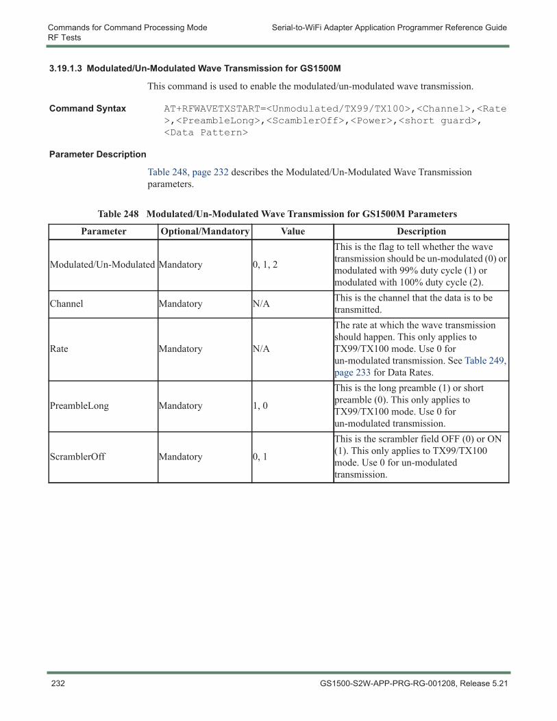
Commands for Command Processing Mode Serial-to-WiFi Adapter Application Programmer Reference GuideRF Tests
3.19.1.3 Modulated/Un-Modulated Wave Transmission for GS1500M
This command is used to enable the modulated/un-modulated wave transmission.
Command Syntax AT+RFWAVETXSTART=<Unmodulated/TX99/TX100>,<Channel>,<Rate>,<PreambleLong>,<ScamblerOff>,<Power>,<short guard>,<Data Pattern>
Parameter Description
Table 248, page 232 describes the Modulated/Un-Modulated Wave Transmission parameters.
Table 248 Modulated/Un-Modulated Wave Transmission for GS1500M Parameters
Parameter Optional/Mandatory Value Description
Modulated/Un-Modulated Mandatory 0, 1, 2
This is the flag to tell whether the wave transmission should be un-modulated (0) or modulated with 99% duty cycle (1) or modulated with 100% duty cycle (2).
Channel Mandatory N/A This is the channel that the data is to be transmitted.
Rate Mandatory N/A
The rate at which the wave transmission should happen. This only applies to TX99/TX100 mode. Use 0 for un-modulated transmission. See Table 249, page 233 for Data Rates.
PreambleLong Mandatory 1, 0
This is the long preamble (1) or short preamble (0). This only applies to TX99/TX100 mode. Use 0 for un-modulated transmission.
ScramblerOff Mandatory 0, 1
This is the scrambler field OFF (0) or ON (1). This only applies to TX99/TX100 mode. Use 0 for un-modulated transmission.
232 GS1500-S2W-APP-PRG-RG-001208, Release 5.21
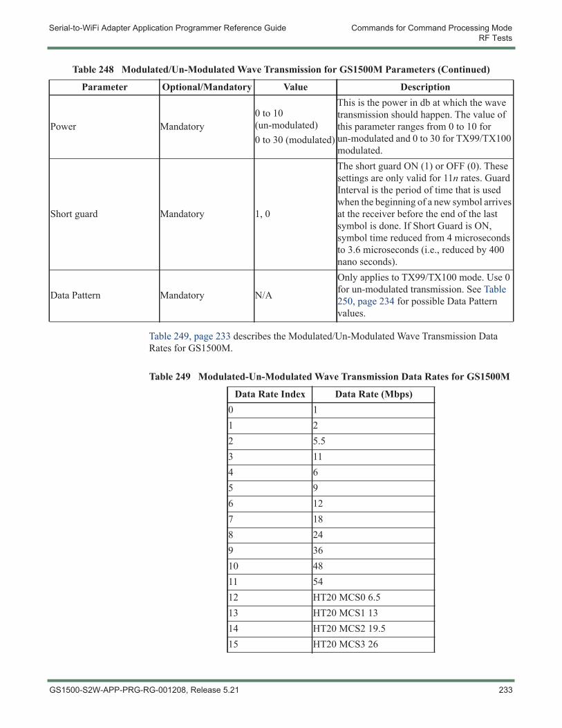
Serial-to-WiFi Adapter Application Programmer Reference Guide Commands for Command Processing ModeRF Tests
Table 249, page 233 describes the Modulated/Un-Modulated Wave Transmission Data Rates for GS1500M.
Power Mandatory0 to 10 (un-modulated)0 to 30 (modulated)
This is the power in db at which the wave transmission should happen. The value of this parameter ranges from 0 to 10 for un-modulated and 0 to 30 for TX99/TX100 modulated.
Short guard Mandatory 1, 0
The short guard ON (1) or OFF (0). These settings are only valid for 11n rates. Guard Interval is the period of time that is used when the beginning of a new symbol arrives at the receiver before the end of the last symbol is done. If Short Guard is ON, symbol time reduced from 4 microseconds to 3.6 microseconds (i.e., reduced by 400 nano seconds).
Data Pattern Mandatory N/A
Only applies to TX99/TX100 mode. Use 0 for un-modulated transmission. See Table 250, page 234 for possible Data Pattern values.
Table 248 Modulated/Un-Modulated Wave Transmission for GS1500M Parameters (Continued)
Parameter Optional/Mandatory Value Description
Table 249 Modulated-Un-Modulated Wave Transmission Data Rates for GS1500M
Data Rate Index Data Rate (Mbps)0 11 22 5.53 114 65 96 127 188 249 3610 4811 5412 HT20 MCS0 6.513 HT20 MCS1 1314 HT20 MCS2 19.515 HT20 MCS3 26
GS1500-S2W-APP-PRG-RG-001208, Release 5.21 233
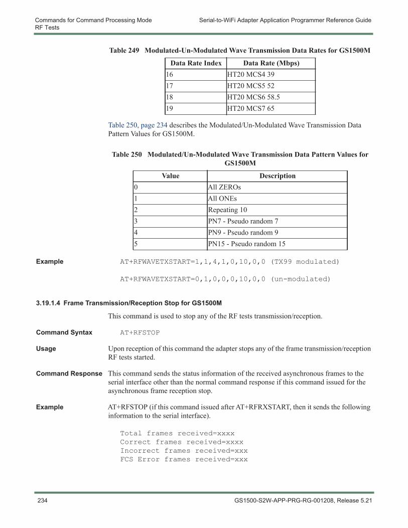
Commands for Command Processing Mode Serial-to-WiFi Adapter Application Programmer Reference GuideRF Tests
Table 250, page 234 describes the Modulated/Un-Modulated Wave Transmission Data Pattern Values for GS1500M.
Example AT+RFWAVETXSTART=1,1,4,1,0,10,0,0 (TX99 modulated)
AT+RFWAVETXSTART=0,1,0,0,0,10,0,0 (un-modulated)
3.19.1.4 Frame Transmission/Reception Stop for GS1500M
This command is used to stop any of the RF tests transmission/reception.
Command Syntax AT+RFSTOP
Usage Upon reception of this command the adapter stops any of the frame transmission/reception RF tests started.
Command Response This command sends the status information of the received asynchronous frames to the serial interface other than the normal command response if this command issued for the asynchronous frame reception stop.
Example AT+RFSTOP (if this command issued after AT+RFRXSTART, then it sends the following information to the serial interface).
Total frames received=xxxxCorrect frames received=xxxxIncorrect frames received=xxxFCS Error frames received=xxx
16 HT20 MCS4 3917 HT20 MCS5 5218 HT20 MCS6 58.519 HT20 MCS7 65
Table 250 Modulated/Un-Modulated Wave Transmission Data Pattern Values for GS1500M
Value Description0 All ZEROs1 All ONEs2 Repeating 103 PN7 - Pseudo random 74 PN9 - Pseudo random 95 PN15 - Pseudo random 15
Table 249 Modulated-Un-Modulated Wave Transmission Data Rates for GS1500M
Data Rate Index Data Rate (Mbps)
234 GS1500-S2W-APP-PRG-RG-001208, Release 5.21
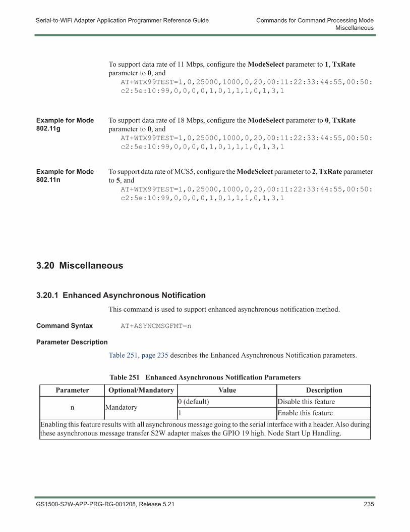
Serial-to-WiFi Adapter Application Programmer Reference Guide Commands for Command Processing ModeMiscellaneous
To support data rate of 11 Mbps, configure the ModeSelect parameter to 1, TxRate parameter to 0, and
AT+WTX99TEST=1,0,25000,1000,0,20,00:11:22:33:44:55,00:50:c2:5e:10:99,0,0,0,0,1,0,1,1,1,0,1,3,1
Example for Mode 802.11g
To support data rate of 18 Mbps, configure the ModeSelect parameter to 0, TxRate parameter to 0, and
AT+WTX99TEST=1,0,25000,1000,0,20,00:11:22:33:44:55,00:50:c2:5e:10:99,0,0,0,0,1,0,1,1,1,0,1,3,1
Example for Mode 802.11n
To support data rate of MCS5, configure the ModeSelect parameter to 2, TxRate parameter to 5, and
AT+WTX99TEST=1,0,25000,1000,0,20,00:11:22:33:44:55,00:50:c2:5e:10:99,0,0,0,0,1,0,1,1,1,0,1,3,1
3.20 Miscellaneous
3.20.1 Enhanced Asynchronous NotificationThis command is used to support enhanced asynchronous notification method.
Command Syntax AT+ASYNCMSGFMT=n
Parameter Description
Table 251, page 235 describes the Enhanced Asynchronous Notification parameters.
Table 251 Enhanced Asynchronous Notification Parameters
Parameter Optional/Mandatory Value Description
n Mandatory0 (default) Disable this feature1 Enable this feature
Enabling this feature results with all asynchronous message going to the serial interface with a header. Also during these asynchronous message transfer S2W adapter makes the GPIO 19 high. Node Start Up Handling.
GS1500-S2W-APP-PRG-RG-001208, Release 5.21 235
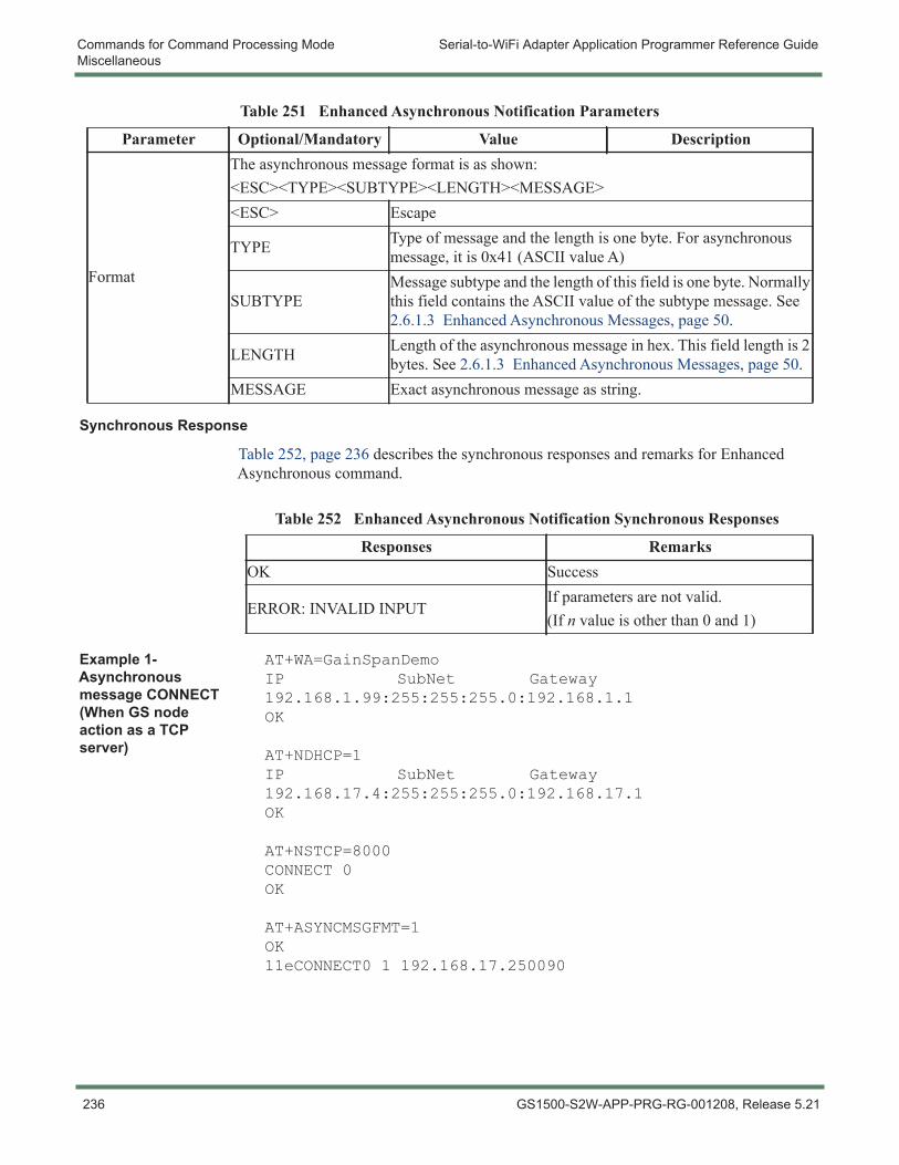
Commands for Command Processing Mode Serial-to-WiFi Adapter Application Programmer Reference GuideMiscellaneous
Synchronous Response
Table 252, page 236 describes the synchronous responses and remarks for Enhanced Asynchronous command.
Example 1- Asynchronous message CONNECT (When GS node action as a TCP server)
AT+WA=GainSpanDemoIP SubNet Gateway192.168.1.99:255:255:255.0:192.168.1.1OK
AT+NDHCP=1IP SubNet Gateway192.168.17.4:255:255:255.0:192.168.17.1OK
AT+NSTCP=8000CONNECT 0OK
AT+ASYNCMSGFMT=1OK11eCONNECT0 1 192.168.17.250090
Format
The asynchronous message format is as shown:<ESC><TYPE><SUBTYPE><LENGTH><MESSAGE><ESC> Escape
TYPE Type of message and the length is one byte. For asynchronous message, it is 0x41 (ASCII value A)
SUBTYPEMessage subtype and the length of this field is one byte. Normally this field contains the ASCII value of the subtype message. See 2.6.1.3 Enhanced Asynchronous Messages, page 50.
LENGTH Length of the asynchronous message in hex. This field length is 2 bytes. See 2.6.1.3 Enhanced Asynchronous Messages, page 50.
MESSAGE Exact asynchronous message as string.
Table 251 Enhanced Asynchronous Notification Parameters
Parameter Optional/Mandatory Value Description
Table 252 Enhanced Asynchronous Notification Synchronous Responses
Responses RemarksOK Success
ERROR: INVALID INPUTIf parameters are not valid.(If n value is other than 0 and 1)
236 GS1500-S2W-APP-PRG-RG-001208, Release 5.21
Serial-to-WiFi Adapter Application Programmer Reference Guide Commands for Command Processing ModeMiscellaneous
3.20.2 Node Start Up Handling For proper synchronization between host micro controller (MCU) and S2W node, the following steps must be followed:
1. In case of UART interface, host MCU sends dummy ‘AT’ command and waits for response from the S2W node during boot up. The host MCU must continuously send these dummy ‘AT’ commands till ‘OK’ response is received from S2W node.
2. In case of SPI interface, host MCU must check the status of host wake-up signal (GPIO28 for GS1500M) during boot up. Once host wake-up signal is HIGH, then the host must read the “Serial2WiFi APP” banner which is queued for transmission at the GainSpan node’s SPI interface at this point. To do so, it can simply repeatedly transmit 64 bytes of idle characters (F5) over the SPI line and read the characters transmitted by the GainSpan node (“Serial2WiFi APP” banner) until it sees the host wake-up signal line has been brought LOW, indicating that all characters have been read from the GainSpan node. This completes the initialization process. At this point, the host MCU can send ‘AT’ commands to the GainSpan node. MCU should not issue a reset using the ext_reset_n signal until this initialization process is completed.
3. If for some reason host MCU getting reset, then S2W adapter must be explicitly reset using EXT_RESET pin and the MCU should wait for the host wake-up signal become high in case of SPI interface. However if reset provision is not available, then host MCU must continuously send dummy ‘AT’ commands till ‘OK’ response is received from S2W adapter.
GS1500-S2W-APP-PRG-RG-001208, Release 5.21 237
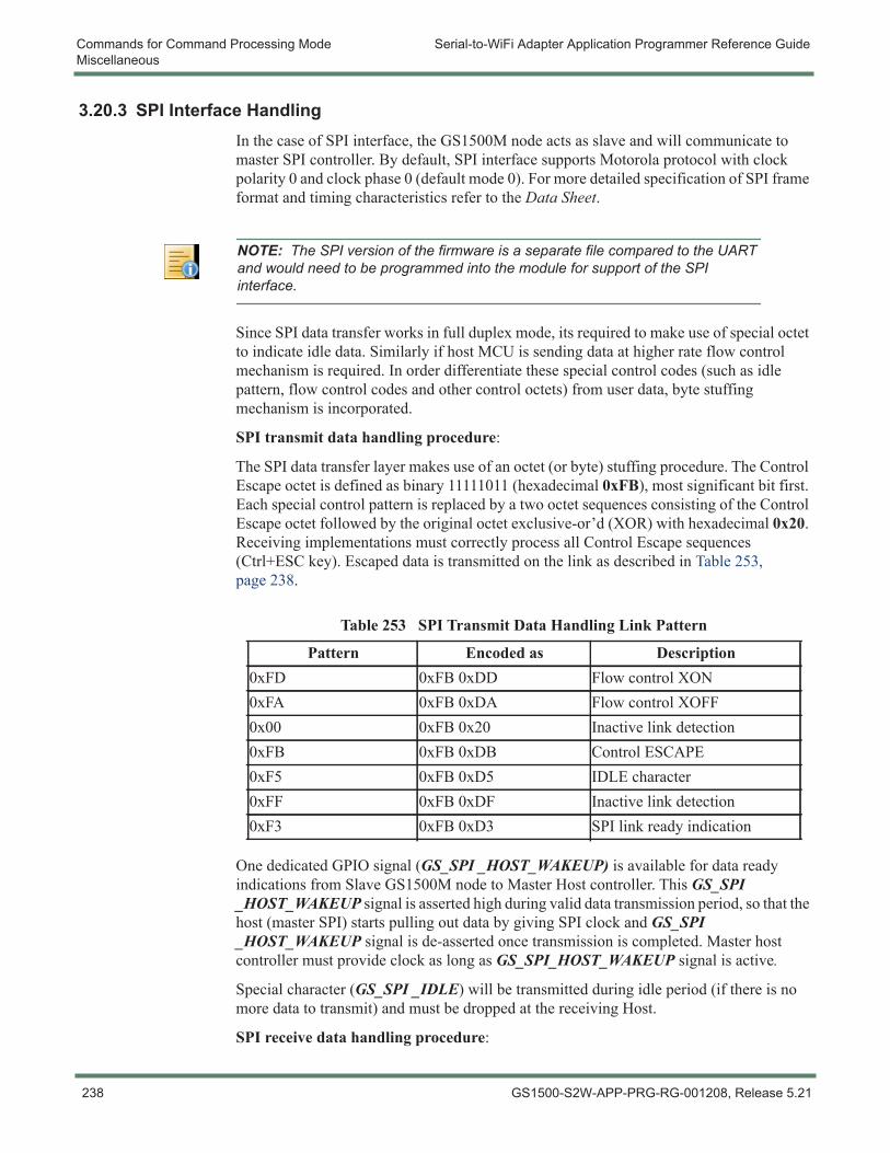
Commands for Command Processing Mode Serial-to-WiFi Adapter Application Programmer Reference GuideMiscellaneous
3.20.3 SPI Interface HandlingIn the case of SPI interface, the GS1500M node acts as slave and will communicate to master SPI controller. By default, SPI interface supports Motorola protocol with clock polarity 0 and clock phase 0 (default mode 0). For more detailed specification of SPI frame format and timing characteristics refer to the Data Sheet.
Since SPI data transfer works in full duplex mode, its required to make use of special octet to indicate idle data. Similarly if host MCU is sending data at higher rate flow control mechanism is required. In order differentiate these special control codes (such as idle pattern, flow control codes and other control octets) from user data, byte stuffing mechanism is incorporated.
SPI transmit data handling procedure:
The SPI data transfer layer makes use of an octet (or byte) stuffing procedure. The Control Escape octet is defined as binary 11111011 (hexadecimal 0xFB), most significant bit first. Each special control pattern is replaced by a two octet sequences consisting of the Control Escape octet followed by the original octet exclusive-or’d (XOR) with hexadecimal 0x20. Receiving implementations must correctly process all Control Escape sequences (Ctrl+ESC key). Escaped data is transmitted on the link as described in Table 253, page 238.
One dedicated GPIO signal (GS_SPI _HOST_WAKEUP) is available for data ready indications from Slave GS1500M node to Master Host controller. This GS_SPI _HOST_WAKEUP signal is asserted high during valid data transmission period, so that the host (master SPI) starts pulling out data by giving SPI clock and GS_SPI _HOST_WAKEUP signal is de-asserted once transmission is completed. Master host controller must provide clock as long as GS_SPI_HOST_WAKEUP signal is active.
Special character (GS_SPI _IDLE) will be transmitted during idle period (if there is no more data to transmit) and must be dropped at the receiving Host.
SPI receive data handling procedure:
NOTE: The SPI version of the firmware is a separate file compared to the UART and would need to be programmed into the module for support of the SPI interface.
Table 253 SPI Transmit Data Handling Link Pattern
Pattern Encoded as Description0xFD 0xFB 0xDD Flow control XON0xFA 0xFB 0xDA Flow control XOFF0x00 0xFB 0x20 Inactive link detection0xFB 0xFB 0xDB Control ESCAPE0xF5 0xFB 0xD5 IDLE character0xFF 0xFB 0xDF Inactive link detection0xF3 0xFB 0xD3 SPI link ready indication
238 GS1500-S2W-APP-PRG-RG-001208, Release 5.21

Serial-to-WiFi Adapter Application Programmer Reference Guide Commands for Command Processing ModeMiscellaneous
Since byte stuffing is used, each Control Escape octet must be removed and the next immediate octet is exclusive-or’d (XOR) with hexadecimal 0x20. If received buffer has reached the upper water mark, then XOFF character will be sent out informing the host to stop transmitting actual data. After receiving XOFF character host must stop transmitting actual data and can send IDLE bytes, until the XON is received. Once the host receives XON, then it may resume the valid data transmissions.
Special control byte IDLE will be dropped at receiver.
3.20.4 Pin Connection for SPI InterfaceTable 254, page 239 describes the pin connection for the SPI interface.
3.20.5 Factory DefaultThe Serial2WiFi adapter stores the factory defaults to its flash; currently supporting the MAC addresses and the following fields as factory default. If the factory default MAC address location contains a valid address, then the Serial2WiFi adapter reads and uses it as the MAC address, otherwise it use the default MAC as it MAC address.
The factory default location starts at 126Kbytes of second application flash (i.e., physical address 0x0801f800) and the Serial-to-WiFi stores the factory default MAC address in the following format:
Parameter Description
Table 255, page 239 describes the Firmware Upgrade parameters.
Table 254 Pin Connection for SPI Interface
Host MCU S2W Node RemarksMSPI_DOUT SSPI_DIN N/AMSPI_DIN SSPI_DOUT N/AMSPI_SS SSPI_SS N/AMSPI_CLK SSPI_CLK N/AGPIO GPIO28 Host wake-up signal. Ground Ground Ground
Checksum (1 byte) Length (1 byte) MAC Address (6 byte) in Hex
Table 255 Factory Default Parameters
Parameter Optional/Mandatory Value Description
Checksum Mandatory N/A The simple byte wise of both length and MAC address.
Length Mandatory N/A The length in bytes of the MAC address and length (here it is 7).
MAC Address Mandatory N/A The user can override the factory default MAC address by using the AT command.
GS1500-S2W-APP-PRG-RG-001208, Release 5.21 239

Commands for Command Processing Mode Serial-to-WiFi Adapter Application Programmer Reference GuideMiscellaneous
The other fields of the factory default section stores in the following format.
Checksum (1 byte) Type (1 byte) Length (1 byte) Data
240 GS1500-S2W-APP-PRG-RG-001208, Release 5.21
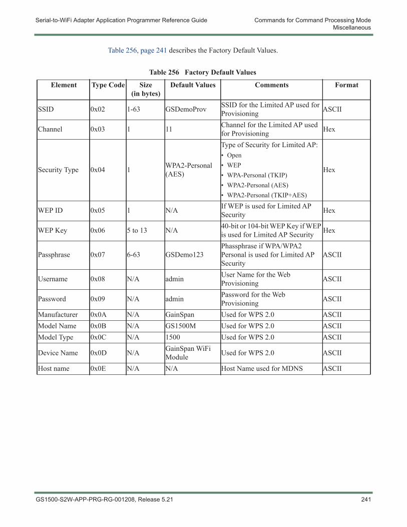
Serial-to-WiFi Adapter Application Programmer Reference Guide Commands for Command Processing ModeMiscellaneous
Table 256, page 241 describes the Factory Default Values.
Table 256 Factory Default Values
Element Type Code Size (in bytes)
Default Values Comments Format
SSID 0x02 1-63 GSDemoProv SSID for the Limited AP used for Provisioning ASCII
Channel 0x03 1 11 Channel for the Limited AP used for Provisioning Hex
Security Type 0x04 1 WPA2-Personal (AES)
Type of Security for Limited AP:• Open• WEP• WPA-Personal (TKIP)• WPA2-Personal (AES)• WPA2-Personal (TKIP+AES)
Hex
WEP ID 0x05 1 N/A If WEP is used for Limited AP Security Hex
WEP Key 0x06 5 to 13 N/A 40-bit or 104-bit WEP Key if WEP is used for Limited AP Security Hex
Passphrase 0x07 6-63 GSDemo123Phassphrase if WPA/WPA2 Personal is used for Limited AP Security
ASCII
Username 0x08 N/A admin User Name for the Web Provisioning ASCII
Password 0x09 N/A admin Password for the Web Provisioning ASCII
Manufacturer 0x0A N/A GainSpan Used for WPS 2.0 ASCIIModel Name 0x0B N/A GS1500M Used for WPS 2.0 ASCIIModel Type 0x0C N/A 1500 Used for WPS 2.0 ASCII
Device Name 0x0D N/A GainSpan WiFi Module Used for WPS 2.0 ASCII
Host name 0x0E N/A N/A Host Name used for MDNS ASCII
GS1500-S2W-APP-PRG-RG-001208, Release 5.21 241
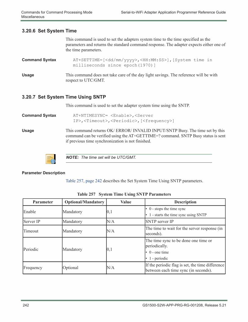
Commands for Command Processing Mode Serial-to-WiFi Adapter Application Programmer Reference GuideMiscellaneous
3.20.6 Set System TimeThis command is used to set the adapters system time to the time specified as the parameters and returns the standard command response. The adapter expects either one of the time parameters.
Command Syntax AT+SETTIME=[<dd/mm/yyyy>,<HH:MM:SS>],[System time in milliseconds since epoch(1970)]
Usage This command does not take care of the day light savings. The reference will be with respect to UTC/GMT.
3.20.7 Set System Time Using SNTPThis command is used to set the adapter system time using the SNTP.
Command Syntax AT+NTIMESYNC= <Enable>,<Server IP>,<Timeout>,<Periodic>,[<frequency>]
Usage This command returns OK/ ERROR/ INVALID INPUT/SNTP Busy. The time set by this command can be verified using the AT+GETTIME=? command. SNTP Busy status is sent if previous time synchronization is not finished.
Parameter Description
Table 257, page 242 describes the Set System Time Using SNTP parameters.
NOTE: The time set will be UTC/GMT.
Table 257 System Time Using SNTP Parameters
Parameter Optional/Mandatory Value Description
Enable Mandatory 0,1• 0 - stops the time sync• 1 - starts the time sync using SNTP
Server IP Mandatory N/A SNTP server IP
Timeout Mandatory N/A The time to wait for the server response (in seconds).
Periodic Mandatory 0,1
The time sync to be done one time or periodically.• 0 - one time• 1 - periodic
Frequency Optional N/A If the periodic flag is set, the time difference between each time sync (in seconds).
242 GS1500-S2W-APP-PRG-RG-001208, Release 5.21
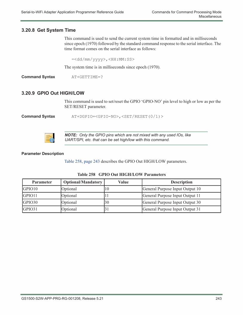
Serial-to-WiFi Adapter Application Programmer Reference Guide Commands for Command Processing ModeMiscellaneous
3.20.8 Get System TimeThis command is used to send the current system time in formatted and in milliseconds since epoch (1970) followed by the standard command response to the serial interface. The time format comes on the serial interface as follows:
=<dd/mm/yyyy>,<HH:MM:SS>
The system time is in milliseconds since epoch (1970).
Command Syntax AT+GETTIME=?
3.20.9 GPIO Out HIGH/LOWThis command is used to set/reset the GPIO ‘GPIO-NO’ pin level to high or low as per the SET/RESET parameter.
Command Syntax AT+DGPIO=<GPIO-NO>,<SET/RESET(0/1)>
Parameter Description
Table 258, page 243 describes the GPIO Out HIGH/LOW parameters.
NOTE: Only the GPIO pins which are not mixed with any used IOs, like UART/SPI, etc. that can be set high/low with this command.
Table 258 GPIO Out HIGH/LOW Parameters
Parameter Optional/Mandatory Value DescriptionGPIO10 Optional 10 General Purpose Input Output 10GPIO11 Optional 11 General Purpose Input Output 11GPIO30 Optional 30 General Purpose Input Output 30GPIO31 Optional 31 General Purpose Input Output 31
GS1500-S2W-APP-PRG-RG-001208, Release 5.21 243
Commands for Command Processing Mode Serial-to-WiFi Adapter Application Programmer Reference GuideMiscellaneous
3.20.10 Error Counts
This command is used to get error count statistics.
Command Syntax AT+ERRCOUNT=?
Usage The error counts include:
– Watchdog reset counts
– Software reset counts
– WLAN abort/assert counts
3.20.11 VersionThis command is used to return version information.
Command Syntax AT+VER=?
– Serial-to-WiFi version
– GainSpan Embedded Platform Software version
– WLAN firmware version
The command to get more details of the S2W version.
AT+VER=??
Command Response This command returns more information along with the above response of the S2W binary followed by the standard command response to the serial host.
– Serial-to-WiFi binary type
– Serial-to-WiFi Release type
244 GS1500-S2W-APP-PRG-RG-001208, Release 5.21
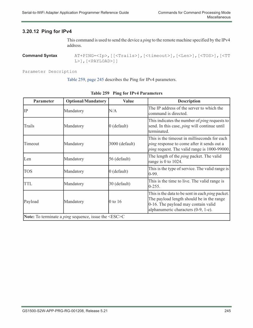
Serial-to-WiFi Adapter Application Programmer Reference Guide Commands for Command Processing ModeMiscellaneous
3.20.12 Ping for IPv4This command is used to send the device a ping to the remote machine specified by the IPv4 address.
Command Syntax AT+PING=<Ip>,[[<Trails>],[<timeout>],[<Len>],[<TOS>],[<TTL>],[<PAYLOAD>]]
Parameter Description
Table 259, page 245 describes the Ping for IPv4 parameters.
Table 259 Ping for IPv4 Parameters
Parameter Optional/Mandatory Value Description
IP Mandatory N/A The IP address of the server to which the command is directed.
Trails Mandatory 0 (default)This indicates the number of ping requests to send. In this case, ping will continue until terminated.
Timeout Mandatory 3000 (default)This is the timeout in milliseconds for each ping response to come after it sends out a ping request. The valid range is 1000-99000.
Len Mandatory 56 (default) The length of the ping packet. The valid range is 0 to 1024.
TOS Mandatory 0 (default) This is the type of service. The valid range is 0-99.
TTL Mandatory 30 (default) This is the time to live. The valid range is 0-255.
Payload Mandatory 0 to 16
This is the data to be sent in each ping packet. The payload length should be in the range 0-16. The payload may contain valid alphanumeric characters (0-9, 1-e).
Note: To terminate a ping sequence, issue the <ESC>C
GS1500-S2W-APP-PRG-RG-001208, Release 5.21 245
Commands for Command Processing Mode Serial-to-WiFi Adapter Application Programmer Reference GuideMiscellaneous
3.20.13 Trace Route
This command is used to Start a trace route operation.
Command Syntax AT+TRACEROUTE=<Ip>,[[<Interval>],[<MaxHops>],[<MinHops>],[<TOS>]]
Usage Upon reception of this command the adapter starts the trace route operation and returns the following information to serial interface along with the standard command response.
<LF>Tracing Route to<space><IP address><space>over a max hops<space>< MaxHops><CR><LF>
During this trace route operation the adapter sends the ping delays and the next hop imp address information to the serial interface one at a line in the following format:
<CR><LF><current TTL ><2 space><1st RTT in 4 bytes>ms<2 space><2nd RTT in 4 bytes>ms<2 space><3rd RTT in 4 bytes>ms<2 space><ip address of hop>
Once the trace route operation complete, the adapter sends the message <CR><LF><CR><LF> Trace Complete <CR><LF> to the serial interface.
246 GS1500-S2W-APP-PRG-RG-001208, Release 5.21

Serial-to-WiFi Adapter Application Programmer Reference Guide Commands for Command Processing ModeMiscellaneous
Parameter Description
Table 260, page 247 describes the Trace Route parameters.
3.20.14 Memory Trace
This command is used to send the memory trace information to the serial interface along with standard command response.
Command Syntax AT+MEMTRACE
Usage The memory trace information contains the following:
– Number Of Allocation
– Number Of Free
– Current Used Memory in bytes
– Peak Memory Usage in bytes
– Memory Details of currently used allocations in the following format:
– <address>,<line number>,<size>,<module name>
– Number of Allocations to be freed
3.20.15 ResetThis command is used to reset the adapter.
Command Syntax AT+RESET
Usage This command forcefully reset the adapter and comes out with a fresh boot message APP Reset-APP SW Reset
Table 260 Trace Route Parameters
Parameter Optional/Mandatory Value DescriptionIP Mandatory N/A The IP address of the remote server.
Interval Mandatory 1000 (default) The interval in milliseconds between each request. The valid range is 1000-99000.
MaxHops Mandatory 30 default The maximum time-to-live. The valid range is 2-99.
MinHops Mandatory 1 (default)The minimum time-to-live. The valid range given should be greater than 1 and less than MaxHops.
TOS Mandatory 0 (default) The type of service. The valid range is 0-99.
GS1500-S2W-APP-PRG-RG-001208, Release 5.21 247
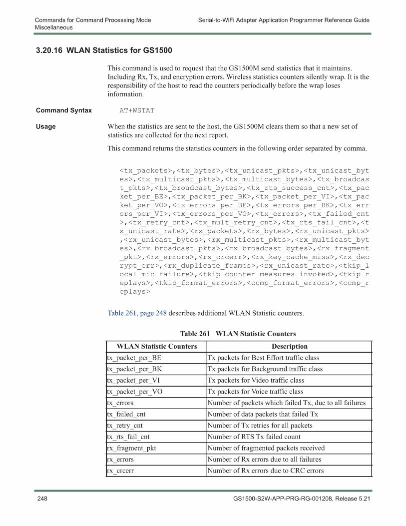
Commands for Command Processing Mode Serial-to-WiFi Adapter Application Programmer Reference GuideMiscellaneous
3.20.16 WLAN Statistics for GS1500
This command is used to request that the GS1500M send statistics that it maintains. Including Rx, Tx, and encryption errors. Wireless statistics counters silently wrap. It is the responsibility of the host to read the counters periodically before the wrap loses information.
Command Syntax AT+WSTAT
Usage When the statistics are sent to the host, the GS1500M clears them so that a new set of statistics are collected for the next report.
This command returns the statistics counters in the following order separated by comma.
<tx_packets>,<tx_bytes>,<tx_unicast_pkts>,<tx_unicast_bytes>,<tx_multicast_pkts>,<tx_multicast_bytes>,<tx_broadcast_pkts>,<tx_broadcast_bytes>,<tx_rts_success_cnt>,<tx_packet_per_BE>,<tx_packet_per_BK>,<tx_packet_per_VI>,<tx_packet_per_VO>,<tx_errors_per_BE>,<tx_errors_per_BK>,<tx_errors_per_VI>,<tx_errors_per_VO>,<tx_errors>,<tx_failed_cnt>,<tx_retry_cnt>,<tx_mult_retry_cnt>,<tx_rts_fail_cnt>,<tx_unicast_rate>,<rx_packets>,<rx_bytes>,<rx_unicast_pkts>,<rx_unicast_bytes>,<rx_multicast_pkts>,<rx_multicast_bytes>,<rx_broadcast_pkts>,<rx_broadcast_bytes>,<rx_fragment_pkt>,<rx_errors>,<rx_crcerr>,<rx_key_cache_miss>,<rx_decrypt_err>,<rx_duplicate_frames>,<rx_unicast_rate>,<tkip_local_mic_failure>,<tkip_counter_measures_invoked>,<tkip_replays>,<tkip_format_errors>,<ccmp_format_errors>,<ccmp_replays>
Table 261, page 248 describes additional WLAN Statistic counters.
Table 261 WLAN Statistic Counters
WLAN Statistic Counters Descriptiontx_packet_per_BE Tx packets for Best Effort traffic classtx_packet_per_BK Tx packets for Background traffic classtx_packet_per_VI Tx packets for Video traffic classtx_packet_per_VO Tx packets for Voice traffic classtx_errors Number of packets which failed Tx, due to all failurestx_failed_cnt Number of data packets that failed Txtx_retry_cnt Number of Tx retries for all packetstx_rts_fail_cnt Number of RTS Tx failed countrx_fragment_pkt Number of fragmented packets receivedrx_errors Number of Rx errors due to all failuresrx_crcerr Number of Rx errors due to CRC errors
248 GS1500-S2W-APP-PRG-RG-001208, Release 5.21

Serial-to-WiFi Adapter Application Programmer Reference Guide Commands for Command Processing ModeMiscellaneous
rx_key_cache_miss Number of Rx errors due to a key not being plumbedrx_decrypt_err Number of Rx errors due to decryption failurerx_duplicate_frames Number of duplicate frames receivedtkip_local_mic_failure Number of TKIP MIC errors detectedtkip_counter measures_invoked Number of times TKIP counter measures were invoked
tkip_replays Number of frames that replayed a TKIP encrypted frame received earlier
tkip_format_errors Number of frames that did not conform to the TKIP frame format
ccmp_format_errors Number of frames that replayed a CCMP encrypted frame received earlier
ccmp_replays Number of frames that replayed a CCMP encrypted frame received earlier
Table 261 WLAN Statistic Counters (Continued)
WLAN Statistic Counters Description
GS1500-S2W-APP-PRG-RG-001208, Release 5.21 249
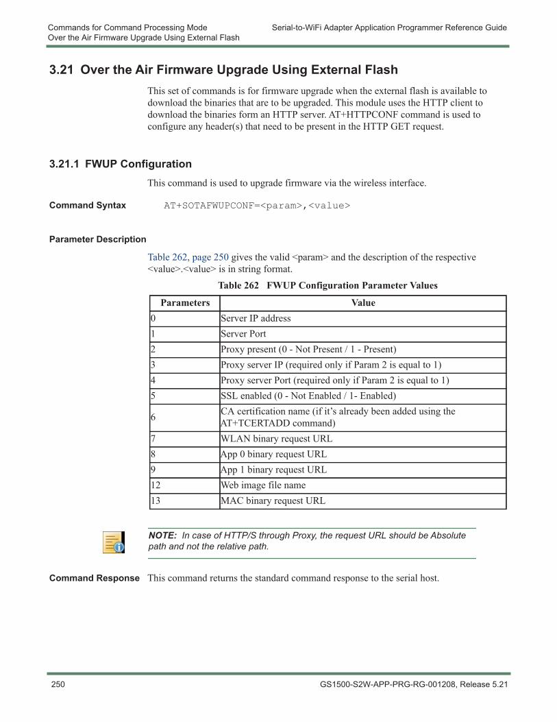
Commands for Command Processing Mode Serial-to-WiFi Adapter Application Programmer Reference GuideOver the Air Firmware Upgrade Using External Flash
3.21 Over the Air Firmware Upgrade Using External FlashThis set of commands is for firmware upgrade when the external flash is available to download the binaries that are to be upgraded. This module uses the HTTP client to download the binaries form an HTTP server. AT+HTTPCONF command is used to configure any header(s) that need to be present in the HTTP GET request.
3.21.1 FWUP ConfigurationThis command is used to upgrade firmware via the wireless interface.
Command Syntax AT+SOTAFWUPCONF=<param>,<value>
Parameter Description
Table 262, page 250 gives the valid <param> and the description of the respective <value>.<value> is in string format.
Command Response This command returns the standard command response to the serial host.
Table 262 FWUP Configuration Parameter Values
Parameters Value0 Server IP address1 Server Port2 Proxy present (0 - Not Present / 1 - Present)3 Proxy server IP (required only if Param 2 is equal to 1)4 Proxy server Port (required only if Param 2 is equal to 1)5 SSL enabled (0 - Not Enabled / 1- Enabled)
6 CA certification name (if it’s already been added using the AT+TCERTADD command)
7 WLAN binary request URL8 App 0 binary request URL9 App 1 binary request URL12 Web image file name13 MAC binary request URL
NOTE: In case of HTTP/S through Proxy, the request URL should be Absolute path and not the relative path.
250 GS1500-S2W-APP-PRG-RG-001208, Release 5.21
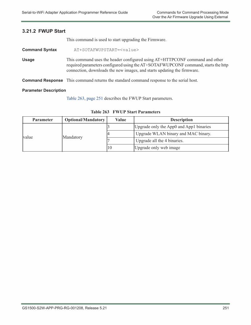
Serial-to-WiFi Adapter Application Programmer Reference Guide Commands for Command Processing ModeOver the Air Firmware Upgrade Using External
3.21.2 FWUP StartThis command is used to start upgrading the Firmware.
Command Syntax AT+SOTAFWUPSTART=<value>
Usage This command uses the header configured using AT+HTTPCONF command and other required parameters configured using the AT+SOTAFWUPCONF command, starts the http connection, downloads the new images, and starts updating the firmware.
Command Response This command returns the standard command response to the serial host.
Parameter Description
Table 263, page 251 describes the FWUP Start parameters.
Table 263 FWUP Start Parameters
Parameter Optional/Mandatory Value Description
value Mandatory
3 Upgrade only the App0 and App1 binaries4 Upgrade WLAN binary and MAC binary.7 Upgrade all the 4 binaries.10 Upgrade only web image
GS1500-S2W-APP-PRG-RG-001208, Release 5.21 251
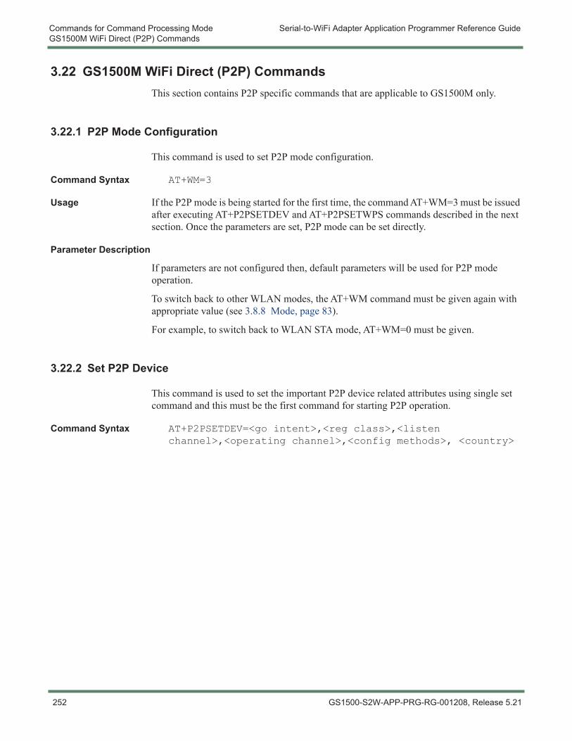
Commands for Command Processing Mode Serial-to-WiFi Adapter Application Programmer Reference GuideGS1500M WiFi Direct (P2P) Commands
3.22 GS1500M WiFi Direct (P2P) CommandsThis section contains P2P specific commands that are applicable to GS1500M only.
3.22.1 P2P Mode Configuration
This command is used to set P2P mode configuration.
Command Syntax AT+WM=3
Usage If the P2P mode is being started for the first time, the command AT+WM=3 must be issued after executing AT+P2PSETDEV and AT+P2PSETWPS commands described in the next section. Once the parameters are set, P2P mode can be set directly.
Parameter Description
If parameters are not configured then, default parameters will be used for P2P mode operation.
To switch back to other WLAN modes, the AT+WM command must be given again with appropriate value (see 3.8.8 Mode, page 83).
For example, to switch back to WLAN STA mode, AT+WM=0 must be given.
3.22.2 Set P2P Device
This command is used to set the important P2P device related attributes using single set command and this must be the first command for starting P2P operation.
Command Syntax AT+P2PSETDEV=<go intent>,<reg class>,<listen channel>,<operating channel>,<config methods>, <country>
252 GS1500-S2W-APP-PRG-RG-001208, Release 5.21
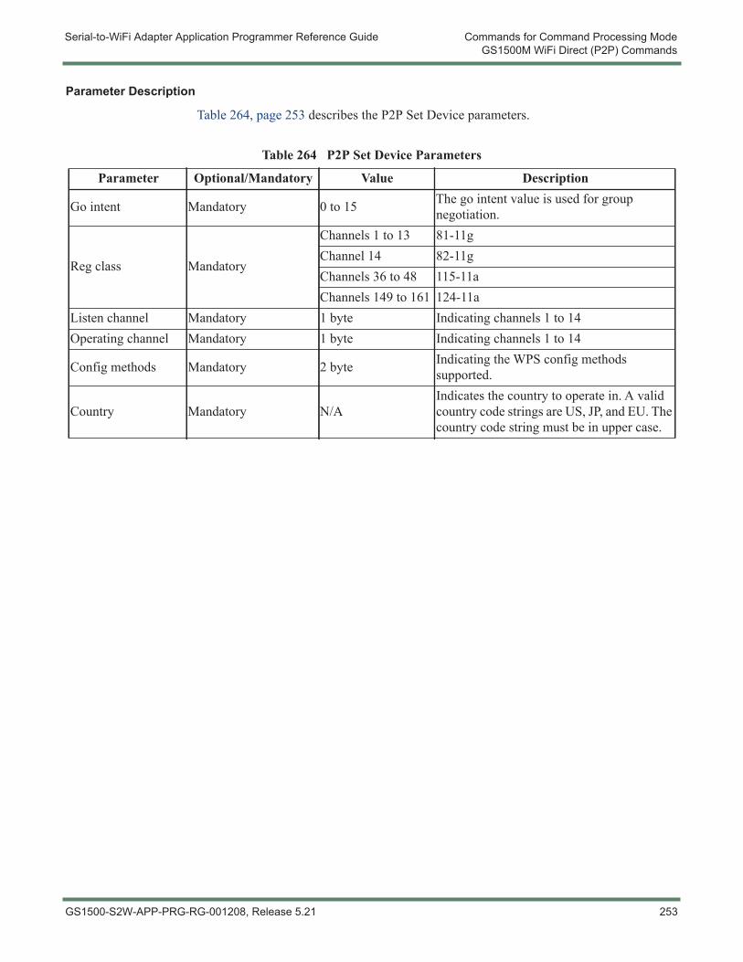
Serial-to-WiFi Adapter Application Programmer Reference Guide Commands for Command Processing ModeGS1500M WiFi Direct (P2P) Commands
Parameter Description
Table 264, page 253 describes the P2P Set Device parameters.
Table 264 P2P Set Device Parameters
Parameter Optional/Mandatory Value Description
Go intent Mandatory 0 to 15 The go intent value is used for group negotiation.
Reg class Mandatory
Channels 1 to 13 81-11gChannel 14 82-11gChannels 36 to 48 115-11aChannels 149 to 161 124-11a
Listen channel Mandatory 1 byte Indicating channels 1 to 14Operating channel Mandatory 1 byte Indicating channels 1 to 14
Config methods Mandatory 2 byte Indicating the WPS config methods supported.
Country Mandatory N/AIndicates the country to operate in. A valid country code strings are US, JP, and EU. The country code string must be in upper case.
GS1500-S2W-APP-PRG-RG-001208, Release 5.21 253
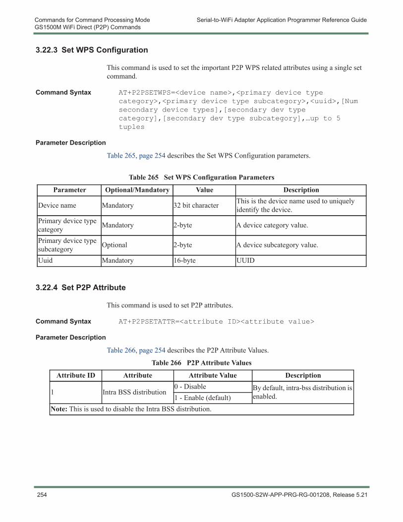
Commands for Command Processing Mode Serial-to-WiFi Adapter Application Programmer Reference GuideGS1500M WiFi Direct (P2P) Commands
3.22.3 Set WPS Configuration
This command is used to set the important P2P WPS related attributes using a single set command.
Command Syntax AT+P2PSETWPS=<device name>,<primary device type category>,<primary device type subcategory>,<uuid>,[Num secondary device types],[secondary dev type category],[secondary dev type subcategory],…up to 5 tuples
Parameter Description
Table 265, page 254 describes the Set WPS Configuration parameters.
3.22.4 Set P2P Attribute
This command is used to set P2P attributes.
Command Syntax AT+P2PSETATTR=<attribute ID><attribute value>
Parameter Description
Table 266, page 254 describes the P2P Attribute Values.
Table 265 Set WPS Configuration Parameters
Parameter Optional/Mandatory Value Description
Device name Mandatory 32 bit character This is the device name used to uniquely identify the device.
Primary device type category Mandatory 2-byte A device category value.
Primary device type subcategory Optional 2-byte A device subcategory value.
Uuid Mandatory 16-byte UUID
Table 266 P2P Attribute Values
Attribute ID Attribute Attribute Value Description
1 Intra BSS distribution0 - Disable By default, intra-bss distribution is
enabled.1 - Enable (default)Note: This is used to disable the Intra BSS distribution.
254 GS1500-S2W-APP-PRG-RG-001208, Release 5.21
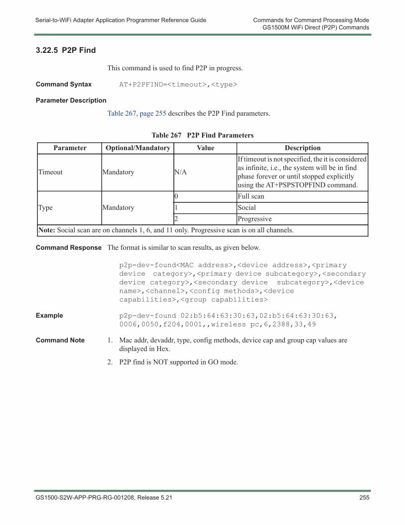
Serial-to-WiFi Adapter Application Programmer Reference Guide Commands for Command Processing ModeGS1500M WiFi Direct (P2P) Commands
3.22.5 P2P Find
This command is used to find P2P in progress.
Command Syntax AT+P2PFIND=<timeout>,<type>
Parameter Description
Table 267, page 255 describes the P2P Find parameters.
Command Response The format is similar to scan results, as given below.
p2p-dev-found<MAC address>,<device address>,<primary device category>,<primary device subcategory>,<secondary device category>,<secondary device subcategory>,<device name>,<channel>,<config methods>,<device capabilities>,<group capabilities>
Example p2p-dev-found 02:b5:64:63:30:63,02:b5:64:63:30:63, 0006,0050,f204,0001,,wireless pc,6,2388,33,49
Command Note 1. Mac addr, devaddr, type, config methods, device cap and group cap values are displayed in Hex.
2. P2P find is NOT supported in GO mode.
Table 267 P2P Find Parameters
Parameter Optional/Mandatory Value Description
Timeout Mandatory N/A
If timeout is not specified, the it is considered as infinite, i.e., the system will be in find phase forever or until stopped explicitly using the AT+PSPSTOPFIND command.
Type Mandatory0 Full scan1 Social2 Progressive
Note: Social scan are on channels 1, 6, and 11 only. Progressive scan is on all channels.
GS1500-S2W-APP-PRG-RG-001208, Release 5.21 255

Commands for Command Processing Mode Serial-to-WiFi Adapter Application Programmer Reference GuideGS1500M WiFi Direct (P2P) Commands
3.22.6 P2P Stop FindThis command is used to stop the P2P find that is currently in progress.
Command Response This command returns the standard command response to the serial interface.
Command Syntax AT+P2PSTOPFIND
3.22.7 P2P Listen
This command is used to start listening to P2P devices. In this state, it responds to provision discovery requests.
Command Syntax AT+P2PLISTEN=[TIMEOUT]
Usage The timeout is an optional parameter specifying the listen duration in seconds. If not specified, it is infinite and can be stopped using AT+P2PSTOPFIND.
3.22.8 P2P Group Owner Start
The command is used start the P2P group owner.
Command Syntax AT+P2PGOSTART=<channel>,[ssid-postfix],[persistent],[persistent group id]
Parameter Description
Table 268, page 256 describes the P2P Group Owner Start parameters.
Table 268 P2P Group Owner Start Parameters
Parameter Optional/Mandatory Value Description
Channel Mandatory N/A This is the channel on which the GO much be started.
SSID-Postfix (optional) Mandatory N/A This parameter specifies the postfix to be
used for the SSID.Note: The GO will be started on channel 6 with SSID “DIRECT-gsnode”
Persistent Mandatory N/A The persistent flag is used to indicate if this is a persistent group.
Persistent Group ID Mandatory N/A
This gives the identifier of the persistent group. If the persistent group with the given ID exists, then it is invoked. Otherwise, a new persistent group is created and stored with the given ID. Currently only 1 persistent group information can be saved.
256 GS1500-S2W-APP-PRG-RG-001208, Release 5.21
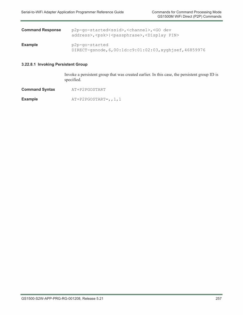
Serial-to-WiFi Adapter Application Programmer Reference Guide Commands for Command Processing ModeGS1500M WiFi Direct (P2P) Commands
Command Response p2p-go-started<ssid>,<channel>,<GO dev address>,<psk>|<passphrase>,<Display PIN>
Example p2p-go-started DIRECT-gsnode,6,00:1d:c9:01:02:03,xyghjsef,46859976
3.22.8.1 Invoking Persistent Group
Invoke a persistent group that was created earlier. In this case, the persistent group ID is specified.
Command Syntax AT+P2PGOSTART
Example AT+P2PGOSTART=,,1,1
GS1500-S2W-APP-PRG-RG-001208, Release 5.21 257
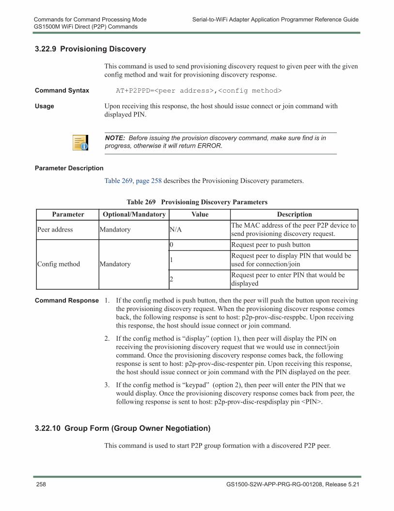
Commands for Command Processing Mode Serial-to-WiFi Adapter Application Programmer Reference GuideGS1500M WiFi Direct (P2P) Commands
3.22.9 Provisioning Discovery
This command is used to send provisioning discovery request to given peer with the given config method and wait for provisioning discovery response.
Command Syntax AT+P2PPD=<peer address>,<config method>
Usage Upon receiving this response, the host should issue connect or join command with displayed PIN.
Parameter Description
Table 269, page 258 describes the Provisioning Discovery parameters.
Command Response 1. If the config method is push button, then the peer will push the button upon receiving the provisioning discovery request. When the provisioning discover response comes back, the following response is sent to host: p2p-prov-disc-resppbc. Upon receiving this response, the host should issue connect or join command.
2. If the config method is “display” (option 1), then peer will display the PIN on receiving the provisioning discovery request that we would use in connect/join command. Once the provisioning discovery response comes back, the following response is sent to host: p2p-prov-disc-respenter pin. Upon receiving this response, the host should issue connect or join command with the PIN displayed on the peer.
3. If the config method is “keypad” (option 2), then peer will enter the PIN that we would display. Once the provisioning discovery response comes back from peer, the following response is sent to host: p2p-prov-disc-respdisplay pin <PIN>.
3.22.10 Group Form (Group Owner Negotiation)
This command is used to start P2P group formation with a discovered P2P peer.
NOTE: Before issuing the provision discovery command, make sure find is in progress, otherwise it will return ERROR.
Table 269 Provisioning Discovery Parameters
Parameter Optional/Mandatory Value Description
Peer address Mandatory N/A The MAC address of the peer P2P device to send provisioning discovery request.
Config method Mandatory
0 Request peer to push button
1 Request peer to display PIN that would be used for connection/join
2 Request peer to enter PIN that would be displayed
258 GS1500-S2W-APP-PRG-RG-001208, Release 5.21
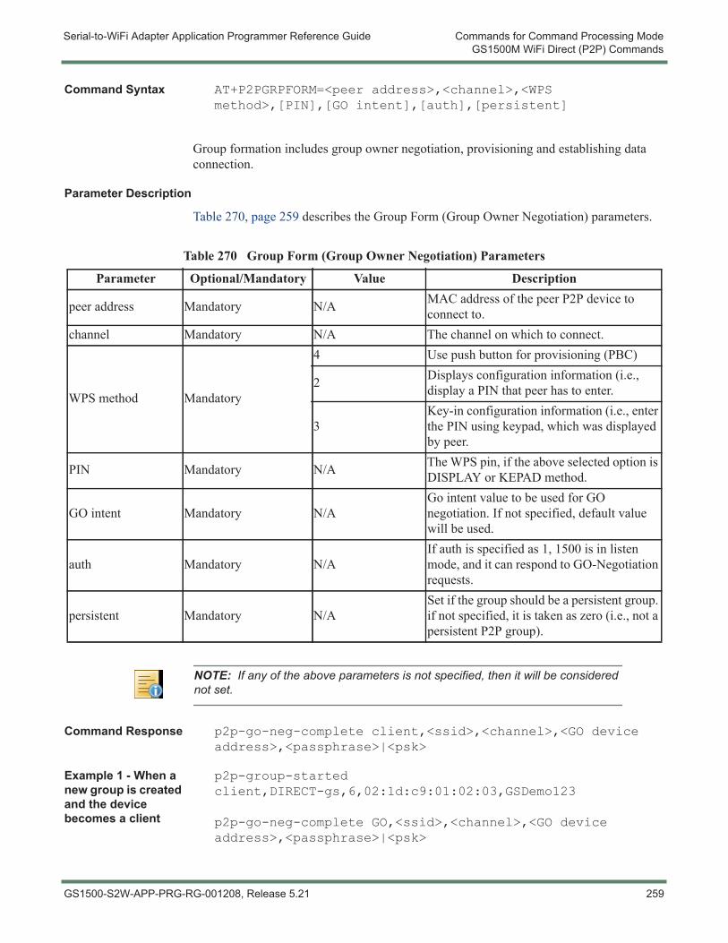
Serial-to-WiFi Adapter Application Programmer Reference Guide Commands for Command Processing ModeGS1500M WiFi Direct (P2P) Commands
Command Syntax AT+P2PGRPFORM=<peer address>,<channel>,<WPS method>,[PIN],[GO intent],[auth],[persistent]
Group formation includes group owner negotiation, provisioning and establishing data connection.
Parameter Description
Table 270, page 259 describes the Group Form (Group Owner Negotiation) parameters.
Command Response p2p-go-neg-complete client,<ssid>,<channel>,<GO device address>,<passphrase>|<psk>
Example 1 - When a new group is created and the device becomes a client
p2p-group-started client,DIRECT-gs,6,02:1d:c9:01:02:03,GSDemo123
p2p-go-neg-complete GO,<ssid>,<channel>,<GO device address>,<passphrase>|<psk>
Table 270 Group Form (Group Owner Negotiation) Parameters
Parameter Optional/Mandatory Value Description
peer address Mandatory N/A MAC address of the peer P2P device to connect to.
channel Mandatory N/A The channel on which to connect.
WPS method Mandatory
4 Use push button for provisioning (PBC)
2 Displays configuration information (i.e., display a PIN that peer has to enter.
3Key-in configuration information (i.e., enter the PIN using keypad, which was displayed by peer.
PIN Mandatory N/A The WPS pin, if the above selected option is DISPLAY or KEPAD method.
GO intent Mandatory N/AGo intent value to be used for GO negotiation. If not specified, default value will be used.
auth Mandatory N/AIf auth is specified as 1, 1500 is in listen mode, and it can respond to GO-Negotiation requests.
persistent Mandatory N/ASet if the group should be a persistent group. if not specified, it is taken as zero (i.e., not a persistent P2P group).
NOTE: If any of the above parameters is not specified, then it will be considered not set.
GS1500-S2W-APP-PRG-RG-001208, Release 5.21 259
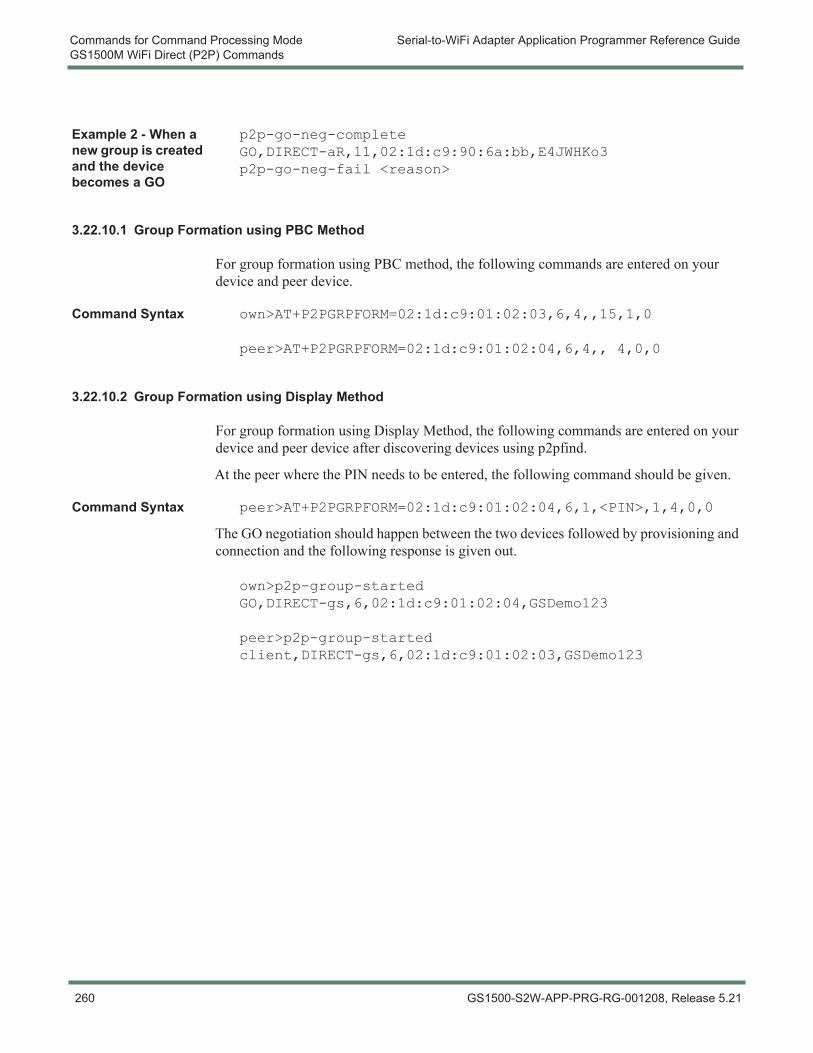
Commands for Command Processing Mode Serial-to-WiFi Adapter Application Programmer Reference GuideGS1500M WiFi Direct (P2P) Commands
Example 2 - When a new group is created and the device becomes a GO
p2p-go-neg-complete GO,DIRECT-aR,11,02:1d:c9:90:6a:bb,E4JWHKo3p2p-go-neg-fail <reason>
3.22.10.1 Group Formation using PBC Method
For group formation using PBC method, the following commands are entered on your device and peer device.
Command Syntax own>AT+P2PGRPFORM=02:1d:c9:01:02:03,6,4,,15,1,0
peer>AT+P2PGRPFORM=02:1d:c9:01:02:04,6,4,, 4,0,0
3.22.10.2 Group Formation using Display Method
For group formation using Display Method, the following commands are entered on your device and peer device after discovering devices using p2pfind.
At the peer where the PIN needs to be entered, the following command should be given.
Command Syntax peer>AT+P2PGRPFORM=02:1d:c9:01:02:04,6,1,<PIN>,1,4,0,0
The GO negotiation should happen between the two devices followed by provisioning and connection and the following response is given out.
own>p2p-group-started GO,DIRECT-gs,6,02:1d:c9:01:02:04,GSDemo123
peer>p2p-group-started client,DIRECT-gs,6,02:1d:c9:01:02:03,GSDemo123
260 GS1500-S2W-APP-PRG-RG-001208, Release 5.21
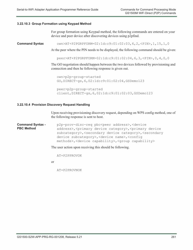
Serial-to-WiFi Adapter Application Programmer Reference Guide Commands for Command Processing ModeGS1500M WiFi Direct (P2P) Commands
3.22.10.3 Group Formation using Keypad Method
For group formation using Keypad method, the following commands are entered on your device and peer device after discovering devices using p2pfind.
Command Syntax own>AT+P2PGRPFORM=02:1d:c9:01:02:03,6,2,<PIN>,1,15,1,0
At the peer where the PIN needs to be displayed, the following command should be given:
peer>AT+P2PGRPFORM=02:1d:c9:01:02:04,6,3,<PIN>,0,4,0,0
The GO negotiation should happen between the two devices followed by provisioning and connection and then he following response is given out.
own>p2p-group-started GO,DIRECT-gs,6,02:1d:c9:01:02:04,GSDemo123
peer>p2p-group-started client,DIRECT-gs,6,02:1d:c9:01:02:03,GSDemo123
3.22.10.4 Provision Discovery Request Handling
Upon receiving provisioning discovery request, depending on WPS config method, one of the following response is sent to host.
Command Syntax - PBC Method
p2p-prov-disc-req pbc<peer address>,<device address>,<primary device category>,<primary device subcategory>,<secondary device category>,<secondary device subcategory>,<device name>,<config methods>,<device capability>,<group capability>
The user action upon receiving this should be following.
AT+P2PPROVOK
or
AT+P2PROVNOK
GS1500-S2W-APP-PRG-RG-001208, Release 5.21 261
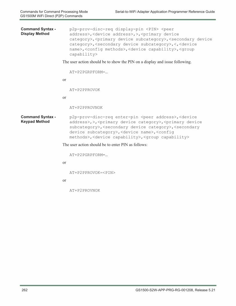
Commands for Command Processing Mode Serial-to-WiFi Adapter Application Programmer Reference GuideGS1500M WiFi Direct (P2P) Commands
Command Syntax - Display Method
p2p-prov-disc-req display-pin <PIN> <peer address>,<device address>,>,<primary device category>,<primary device subcategory>,<secondary device category>,<secondary device subcategory>,<,<device name>,<config methods>,<device capability>,<group capability>
The user action should be to show the PIN on a display and issue following.
AT+P2PGRPFORM=…
or
AT+P2PPROVOK
or
AT+P2PPROVNOK
Command Syntax - Keypad Method
p2p-prov-disc-req enter-pin <peer address>,<device address>,>,<primary device category>,<primary device subcategory>,<secondary device category>,<secondary device subcategory>,<device name>,<config methods>,<device capability>,<group capability>
The user action should be to enter PIN as follows:
AT+P2PGRPFORM=…
or
AT+P2PPROVOK=<PIN>
or
AT+P2PROVNOK
262 GS1500-S2W-APP-PRG-RG-001208, Release 5.21
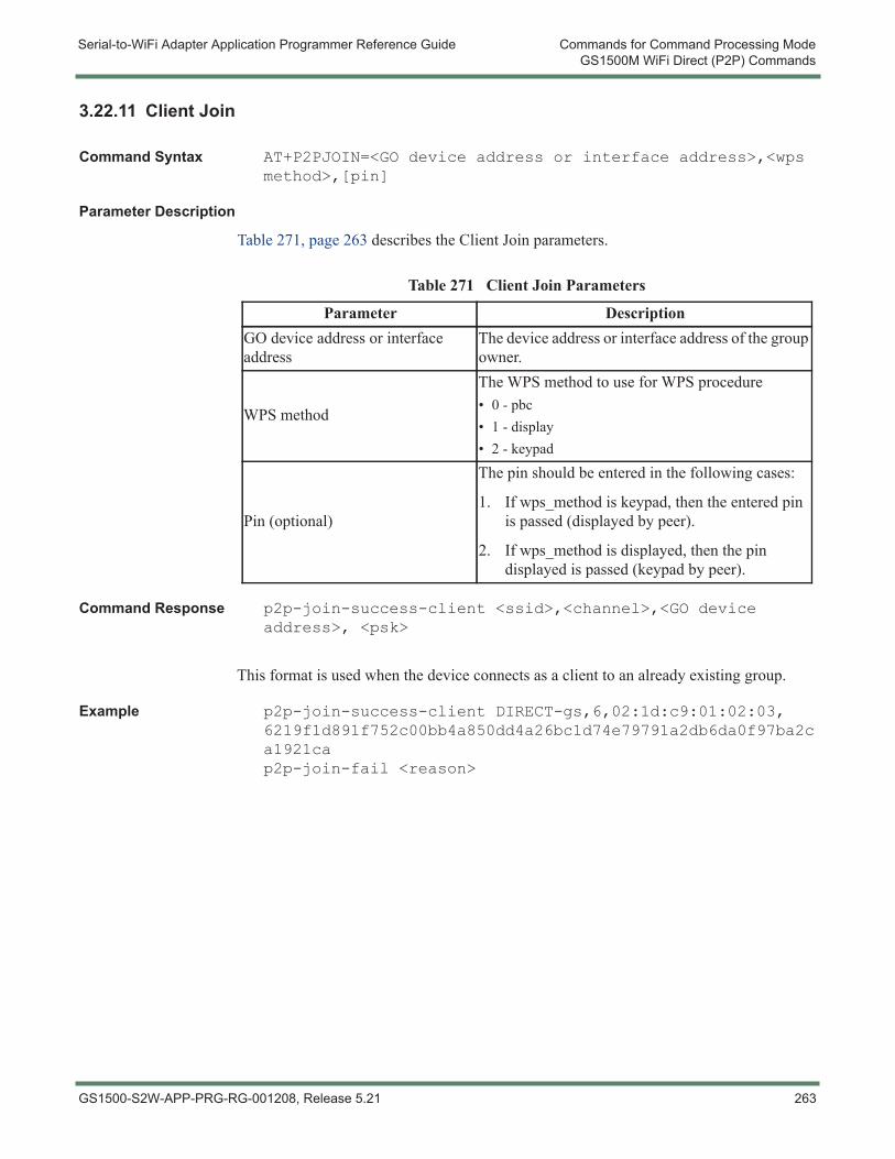
Serial-to-WiFi Adapter Application Programmer Reference Guide Commands for Command Processing ModeGS1500M WiFi Direct (P2P) Commands
3.22.11 Client Join
Command Syntax AT+P2PJOIN=<GO device address or interface address>,<wps method>,[pin]
Parameter Description
Table 271, page 263 describes the Client Join parameters.
Command Response p2p-join-success-client <ssid>,<channel>,<GO device address>, <psk>
This format is used when the device connects as a client to an already existing group.
Example p2p-join-success-client DIRECT-gs,6,02:1d:c9:01:02:03, 6219f1d891f752c00bb4a850dd4a26bc1d74e79791a2db6da0f97ba2ca1921cap2p-join-fail <reason>
Table 271 Client Join Parameters
Parameter DescriptionGO device address or interface address
The device address or interface address of the group owner.
WPS method
The WPS method to use for WPS procedure• 0 - pbc• 1 - display• 2 - keypad
Pin (optional)
The pin should be entered in the following cases:
1. If wps_method is keypad, then the entered pin is passed (displayed by peer).
2. If wps_method is displayed, then the pin displayed is passed (keypad by peer).
GS1500-S2W-APP-PRG-RG-001208, Release 5.21 263
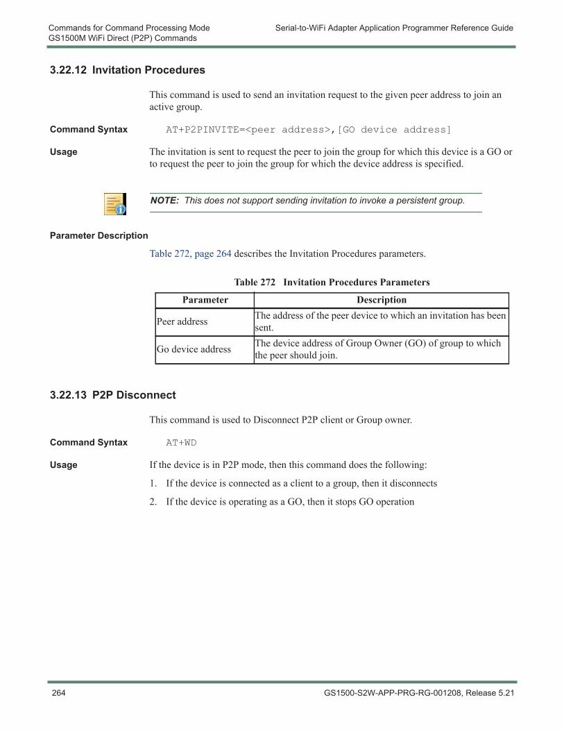
Commands for Command Processing Mode Serial-to-WiFi Adapter Application Programmer Reference GuideGS1500M WiFi Direct (P2P) Commands
3.22.12 Invitation Procedures
This command is used to send an invitation request to the given peer address to join an active group.
Command Syntax AT+P2PINVITE=<peer address>,[GO device address]
Usage The invitation is sent to request the peer to join the group for which this device is a GO or to request the peer to join the group for which the device address is specified.
Parameter Description
Table 272, page 264 describes the Invitation Procedures parameters.
3.22.13 P2P Disconnect
This command is used to Disconnect P2P client or Group owner.
Command Syntax AT+WD
Usage If the device is in P2P mode, then this command does the following:
1. If the device is connected as a client to a group, then it disconnects
2. If the device is operating as a GO, then it stops GO operation
NOTE: This does not support sending invitation to invoke a persistent group.
Table 272 Invitation Procedures Parameters
Parameter Description
Peer address The address of the peer device to which an invitation has been sent.
Go device address The device address of Group Owner (GO) of group to which the peer should join.
264 GS1500-S2W-APP-PRG-RG-001208, Release 5.21
Serial-to-WiFi Adapter Application Programmer Reference Guide Commands for Command Processing ModeGS1500M WiFi Direct (P2P) Commands
3.22.14 P2P Store/Restore NW Connection
This command is used to store and restore NW connection.
Command Syntax AT+STORENWCON
AT+RESTORENEWCONN
Usage The store (AT+STORENWCON) and restore NW connection (AT+RESTORENWCONN) commands store and restore P2P context also. If a device is operating in P2P mode as a client or Group Owner (GO), then store/restore can be used to store the context, go to standby and restore the context. The device will perform the necessary setup and continue to operate in the previous mode. See 3.10.2 Static Configuration of Network Parameters for IPv4, page 136 and 3.10.15 IP Multicast Join, page 156 for command syntax.
GS1500-S2W-APP-PRG-RG-001208, Release 5.21 265

Commands for Command Processing Mode Serial-to-WiFi Adapter Application Programmer Reference GuideGS1500M WiFi Direct (P2P) Commands
266 GS1500-S2W-APP-PRG-RG-001208, Release 5.21
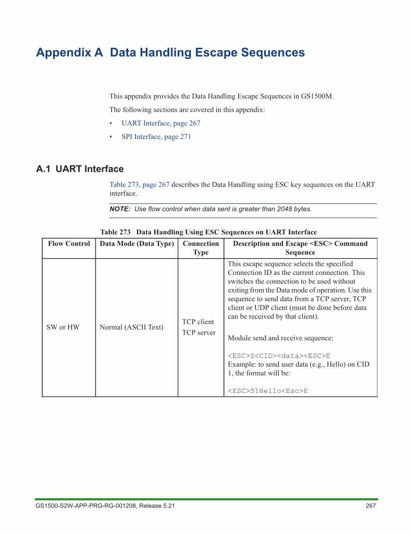
Appendix A Data Handling Escape Sequences
This appendix provides the Data Handling Escape Sequences in GS1500M.
The following sections are covered in this appendix:
• UART Interface, page 267
• SPI Interface, page 271
A.1 UART InterfaceTable 273, page 267 describes the Data Handling using ESC key sequences on the UART interface.
NOTE: Use flow control when data sent is greater than 2048 bytes.
Table 273 Data Handling Using ESC Sequences on UART Interface Flow Control Data Mode (Data Type) Connection
TypeDescription and Escape <ESC> Command
Sequence
SW or HW Normal (ASCII Text)TCP clientTCP server
This escape sequence selects the specified Connection ID as the current connection. This switches the connection to be used without exiting from the Data mode of operation. Use this sequence to send data from a TCP server, TCP client or UDP client (must be done before data can be received by that client).
Module send and receive sequence:
<ESC>S<CID><data><ESC>EExample: to send user data (e.g., Hello) on CID 1, the format will be:
<ESC>S1Hello<Esc>E
GS1500-S2W-APP-PRG-RG-001208, Release 5.21 267
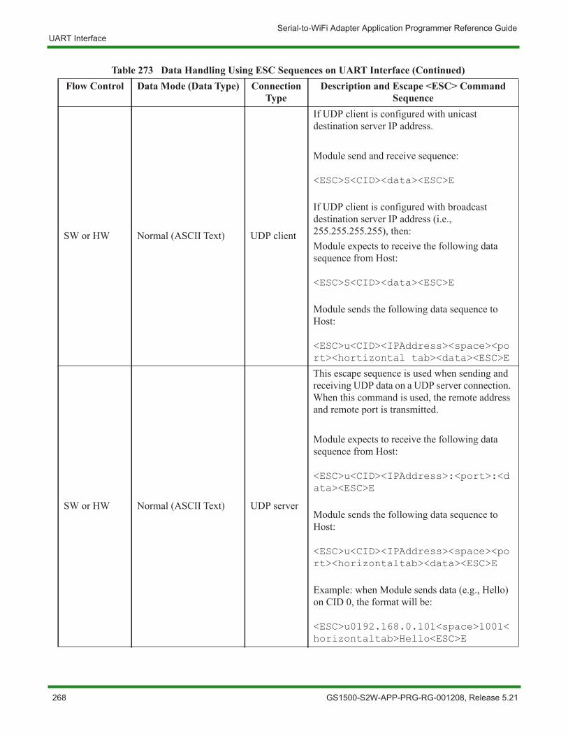
Serial-to-WiFi Adapter Application Programmer Reference GuideUART Interface
SW or HW Normal (ASCII Text) UDP client
If UDP client is configured with unicast destination server IP address.
Module send and receive sequence:
<ESC>S<CID><data><ESC>E
If UDP client is configured with broadcast destination server IP address (i.e., 255.255.255.255), then:Module expects to receive the following data sequence from Host:
<ESC>S<CID><data><ESC>E
Module sends the following data sequence to Host:
<ESC>u<CID><IPAddress><space><port><hortizontal tab><data><ESC>E
SW or HW Normal (ASCII Text) UDP server
This escape sequence is used when sending and receiving UDP data on a UDP server connection. When this command is used, the remote address and remote port is transmitted.
Module expects to receive the following data sequence from Host:
<ESC>u<CID><IPAddress>:<port>:<data><ESC>E
Module sends the following data sequence to Host:
<ESC>u<CID><IPAddress><space><port><horizontaltab><data><ESC>E
Example: when Module sends data (e.g., Hello) on CID 0, the format will be:
<ESC>u0192.168.0.101<space>1001<horizontaltab>Hello<ESC>E
Table 273 Data Handling Using ESC Sequences on UART Interface (Continued)Flow Control Data Mode (Data Type) Connection
TypeDescription and Escape <ESC> Command
Sequence
268 GS1500-S2W-APP-PRG-RG-001208, Release 5.21
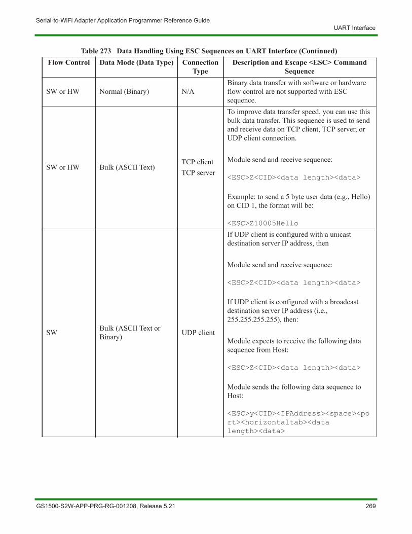
Serial-to-WiFi Adapter Application Programmer Reference GuideUART Interface
SW or HW Normal (Binary) N/ABinary data transfer with software or hardware flow control are not supported with ESC sequence.
SW or HW Bulk (ASCII Text)TCP clientTCP server
To improve data transfer speed, you can use this bulk data transfer. This sequence is used to send and receive data on TCP client, TCP server, or UDP client connection.
Module send and receive sequence:
<ESC>Z<CID><data length><data>
Example: to send a 5 byte user data (e.g., Hello) on CID 1, the format will be:
<ESC>Z10005Hello
SW Bulk (ASCII Text or Binary) UDP client
If UDP client is configured with a unicast destination server IP address, then
Module send and receive sequence:
<ESC>Z<CID><data length><data>
If UDP client is configured with a broadcast destination server IP address (i.e., 255.255.255.255), then:
Module expects to receive the following data sequence from Host:
<ESC>Z<CID><data length><data>
Module sends the following data sequence to Host:
<ESC>y<CID><IPAddress><space><port><horizontaltab><data length><data>
Table 273 Data Handling Using ESC Sequences on UART Interface (Continued)Flow Control Data Mode (Data Type) Connection
TypeDescription and Escape <ESC> Command
Sequence
GS1500-S2W-APP-PRG-RG-001208, Release 5.21 269
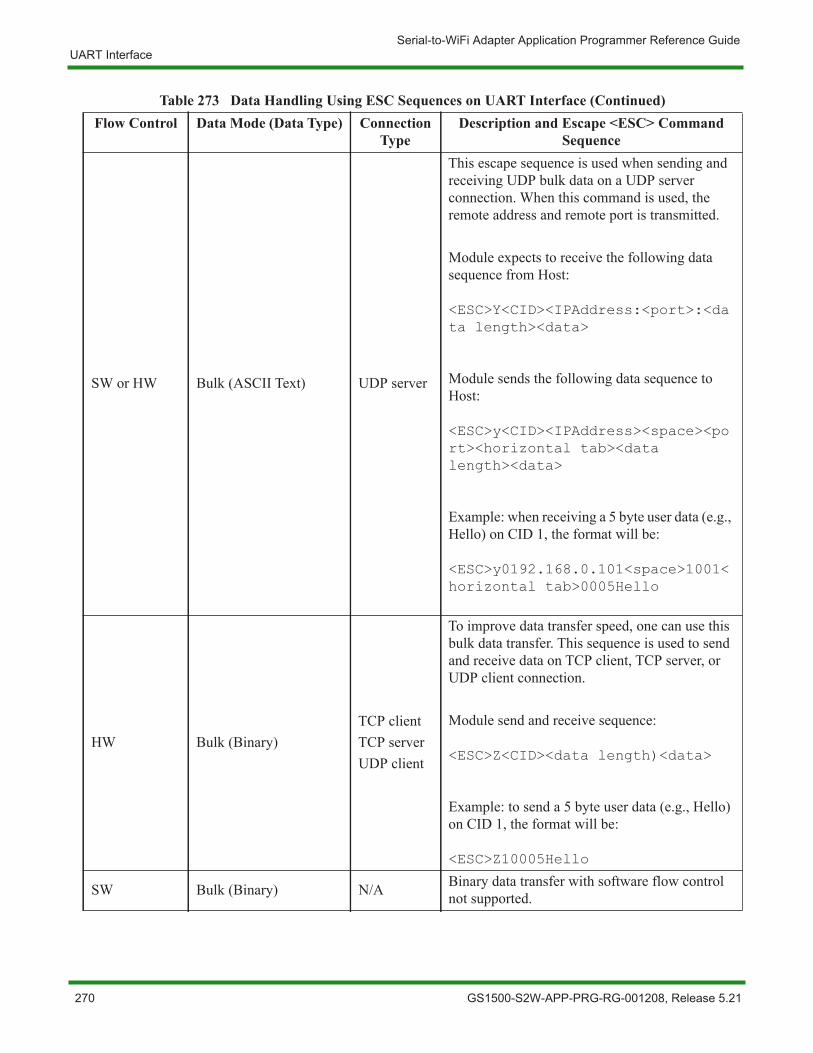
Serial-to-WiFi Adapter Application Programmer Reference GuideUART Interface
SW or HW Bulk (ASCII Text) UDP server
This escape sequence is used when sending and receiving UDP bulk data on a UDP server connection. When this command is used, the remote address and remote port is transmitted.
Module expects to receive the following data sequence from Host:
<ESC>Y<CID><IPAddress:<port>:<data length><data>
Module sends the following data sequence to Host:
<ESC>y<CID><IPAddress><space><port><horizontal tab><data length><data>
Example: when receiving a 5 byte user data (e.g., Hello) on CID 1, the format will be:
<ESC>y0192.168.0.101<space>1001<horizontal tab>0005Hello
HW Bulk (Binary)TCP clientTCP serverUDP client
To improve data transfer speed, one can use this bulk data transfer. This sequence is used to send and receive data on TCP client, TCP server, or UDP client connection.
Module send and receive sequence:
<ESC>Z<CID><data length)<data>
Example: to send a 5 byte user data (e.g., Hello) on CID 1, the format will be:
<ESC>Z10005Hello
SW Bulk (Binary) N/A Binary data transfer with software flow control not supported.
Table 273 Data Handling Using ESC Sequences on UART Interface (Continued)Flow Control Data Mode (Data Type) Connection
TypeDescription and Escape <ESC> Command
Sequence
270 GS1500-S2W-APP-PRG-RG-001208, Release 5.21
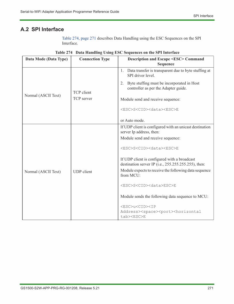
Serial-to-WiFi Adapter Application Programmer Reference GuideSPI Interface
A.2 SPI InterfaceTable 274, page 271 describes Data Handling using the ESC Sequences on the SPI Interface.
Table 274 Data Handling Using ESC Sequences on the SPI Interface Data Mode (Data Type) Connection Type Description and Escape <ESC> Command
Sequence
Normal (ASCII Text)TCP clientTCP server
1. Data transfer is transparent due to byte stuffing at SPI driver level.
2. Byte stuffing must be incorporated in Host controller as per the Adapter guide.
Module send and receive sequence:
<ESC>S<CID><data><ESC>E
or Auto mode.
Normal (ASCII Text) UDP client
If UDP client is configured with an unicast destination server Ip address, then:Module send and receive sequence:
<ESC>S<CID><data><ESC>E
If UDP client is configured with a broadcast destination server IP (i.e., 255.255.255.255), then:Module expects to receive the following data sequence from MCU:
<ESC>S<CID><data>ESC>E
Module sends the following data sequence to MCU:
<ESC>u<CID><IP Address><space><port><horizontal tab><ESC>E
GS1500-S2W-APP-PRG-RG-001208, Release 5.21 271
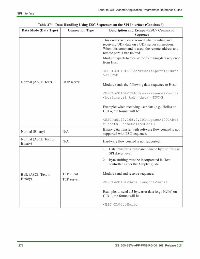
Serial-to-WiFi Adapter Application Programmer Reference GuideSPI Interface
Normal (ASCII Text) UDP server
This escape sequence is used when sending and receiving UDP data on a UDP server connection. When this command is used, the remote address and remote port is transmitted.Module expects to receive the following data sequence from Host:
<ESC>u<CID><IPAddress>:<port>:<data><ESC>E
Module sends the following data sequence to Host:
<ESC>u<CID><IPAddress><space><port><horizontal tab><data><ESC>E
Example: when receiving user data (e.g., Hello) on CID o, the format will be:
<ESC>u0192.168.0.101<space>1001<hortizontal tab>Hello<Esc>E
Normal (Binary) N/A Binary data transfer with software flow control is not supported with ESC sequence.
Normal (ASCII Text or Binary) N/A Hardware flow control is not supported.
Bulk (ASCII Text or Binary)
TCP clientTCP server
1. Data transfer is transparent due to byte stuffing at SPI driver level.
2. Byte stuffing must be incorporated in Host controller as per the Adapter guide.
Module send and receive sequence:
<ESC>Z<CID><data length><data>
Example: to send a 5 byte user data (e.g., Hello) on CID 1, the format will be:
<ESC>Z10005Hello
Table 274 Data Handling Using ESC Sequences on the SPI Interface (Continued)Data Mode (Data Type) Connection Type Description and Escape <ESC> Command
Sequence
272 GS1500-S2W-APP-PRG-RG-001208, Release 5.21
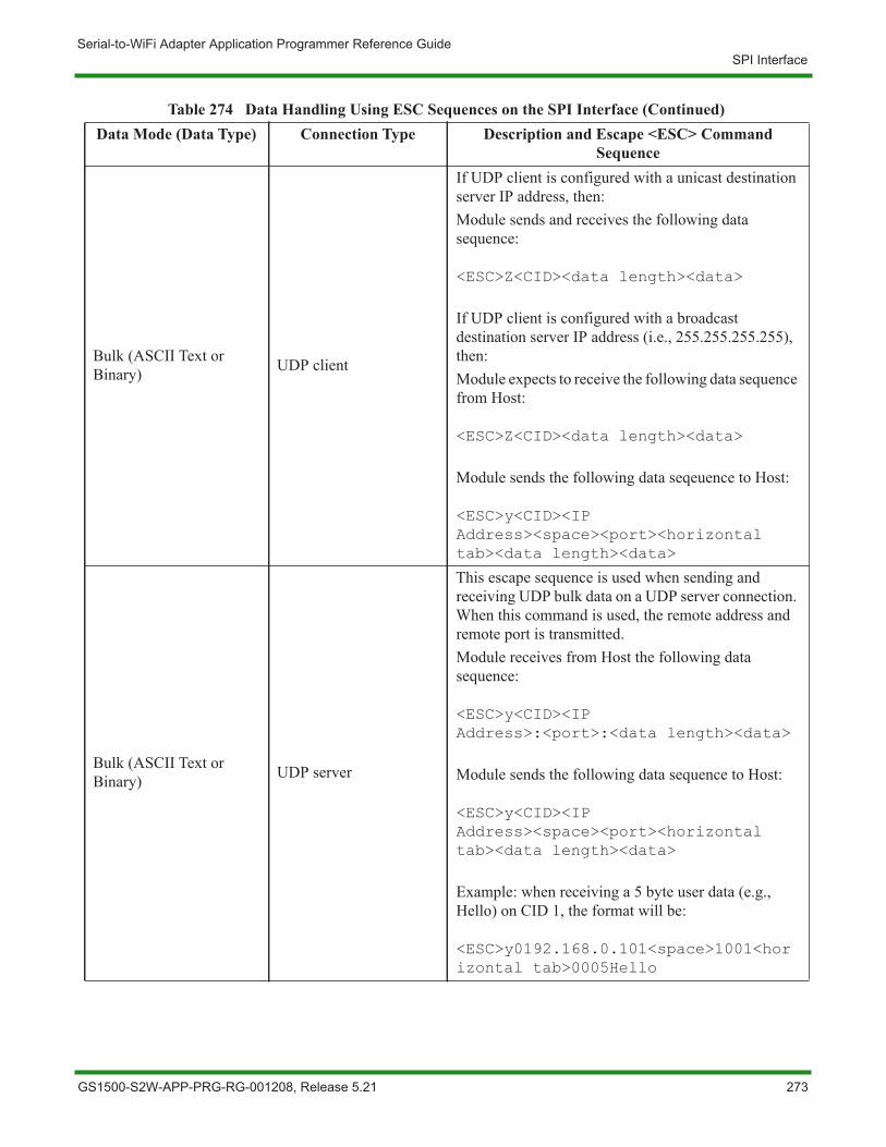
Serial-to-WiFi Adapter Application Programmer Reference GuideSPI Interface
Bulk (ASCII Text or Binary) UDP client
If UDP client is configured with a unicast destination server IP address, then:Module sends and receives the following data sequence:
<ESC>Z<CID><data length><data>
If UDP client is configured with a broadcast destination server IP address (i.e., 255.255.255.255), then:Module expects to receive the following data sequence from Host:
<ESC>Z<CID><data length><data>
Module sends the following data seqeuence to Host:
<ESC>y<CID><IP Address><space><port><horizontal tab><data length><data>
Bulk (ASCII Text or Binary) UDP server
This escape sequence is used when sending and receiving UDP bulk data on a UDP server connection. When this command is used, the remote address and remote port is transmitted.Module receives from Host the following data sequence:
<ESC>y<CID><IP Address>:<port>:<data length><data>
Module sends the following data sequence to Host:
<ESC>y<CID><IP Address><space><port><horizontal tab><data length><data>
Example: when receiving a 5 byte user data (e.g., Hello) on CID 1, the format will be:
<ESC>y0192.168.0.101<space>1001<horizontal tab>0005Hello
Table 274 Data Handling Using ESC Sequences on the SPI Interface (Continued)Data Mode (Data Type) Connection Type Description and Escape <ESC> Command
Sequence
GS1500-S2W-APP-PRG-RG-001208, Release 5.21 273

Serial-to-WiFi Adapter Application Programmer Reference GuideSPI Interface
- This page intentionally left blank -
274 GS1500-S2W-APP-PRG-RG-001208, Release 5.21
Appendix B Serial-to-WiFi Commands
This appendix provides a list of supported Serial-to-WiFi Adapter commands.
The following sections are covered in this appendix:
• Command Interface, page 276
• UART/ADAPTER Interface Configuration, page 277
• Profile Management, page 277
• GSLINK, page 279
• WiFi Interface, page 280
• WiFi Security, page 283
• Wireless Configuration, page 285
• Network Interface, page 287
• Connection Management, page 290
• Power Management, page 293
• Auto Connection, page 294
• RF Test, page 295
• SPI, page 296
• Miscellaneous, page 301
• Default Return Messages, page 304
• Escape Sequence Commands, page 305
GS1500-S2W-APP-PRG-RG-001208, Release 5.21 275
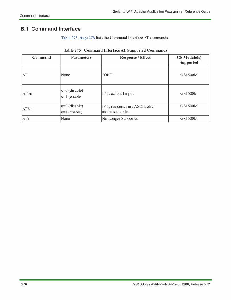
Serial-to-WiFi Adapter Application Programmer Reference GuideCommand Interface
B.1 Command InterfaceTable 275, page 276 lists the Command Interface AT commands.
Table 275 Command Interface AT Supported Commands
Command Parameters Response / Effect GS Module(s) Supported
AT None “OK” GS1500M
ATEnn=0 (disable)n=1 (enable
IF 1, echo all input GS1500M
ATVnn=0 (disable)n=1 (enable)
IF 1, responses are ASCII, else numerical codes
GS1500M
AT? None No Longer Supported GS1500M
276 GS1500-S2W-APP-PRG-RG-001208, Release 5.21

Serial-to-WiFi Adapter Application Programmer Reference GuideUART/ADAPTER Interface Configuration
B.2 UART/ADAPTER Interface ConfigurationTable 276, page 277 lists the UART/ADAPTER Interface AT commands.
B.3 Profile ManagementTable 277, page 278 lists the Profile Management AT commands.
Table 276 UART/ADAPTER Interface Configuration AT Supported Commands
Command Parameters Response / Effect GS Module(s) Supported
ATB= <baudrate>[[,bitsperchar>][,<parity>][,<stopbits]]
UART parameters are immediately reset to values provided. GS1500M
AT&Knn=0 (disable)n=1 (enable)
IF 1, software flow control is enabled GS1500M
AT&Rnn=0 (disable)n=1 (enable)
IF 1, hardware flow control is enabled GS1500M
ATIn n=value
Various Adapter ID information:• 0=OEM ID• 1=Hardware Version• 2=Software Version
GS1500M
AT+WST= <Min scan time>,<Max scan time>
Min scan time is the minimum scan time per channel.Max scan time is the maximum scan time per channel. The Max scan time should always be greater than or equal to Min scan time. Both parameters are in milliseconds.This command also modifies the scan time configured with the ATS5 command.
GS1500M
GS1500-S2W-APP-PRG-RG-001208, Release 5.21 277
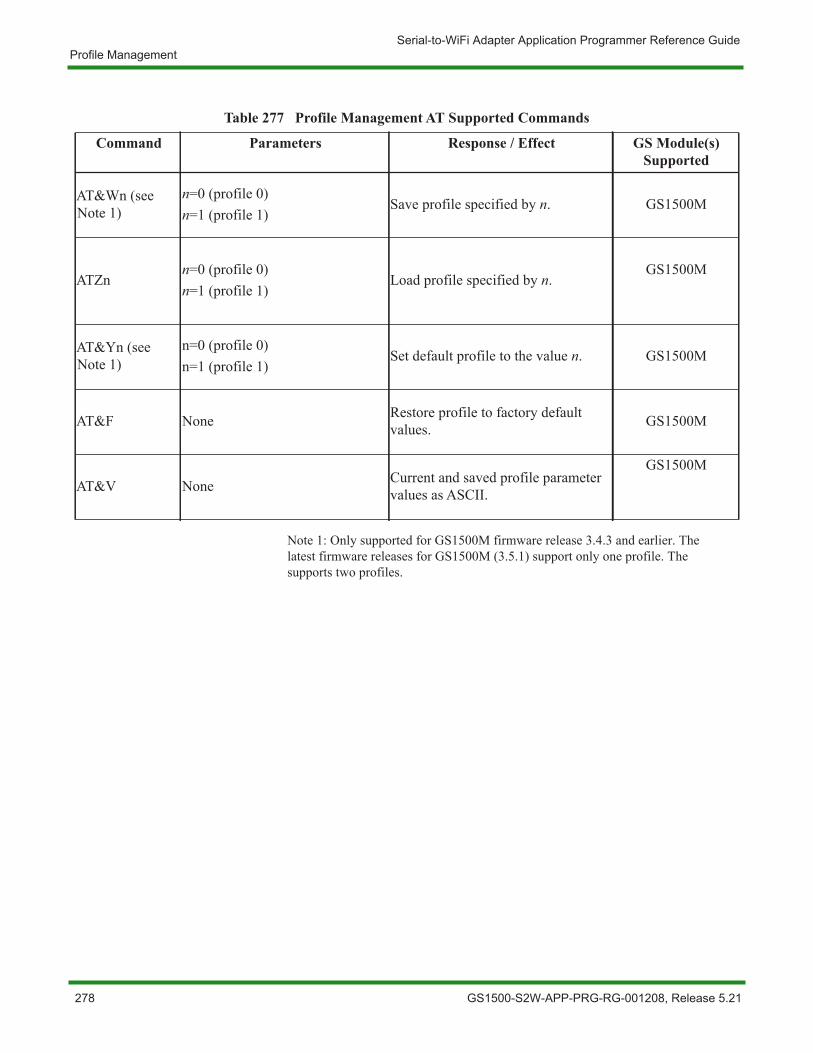
Serial-to-WiFi Adapter Application Programmer Reference GuideProfile Management
Note 1: Only supported for GS1500M firmware release 3.4.3 and earlier. The latest firmware releases for GS1500M (3.5.1) support only one profile. The supports two profiles.
Table 277 Profile Management AT Supported Commands
Command Parameters Response / Effect GS Module(s) Supported
AT&Wn (see Note 1)
n=0 (profile 0)n=1 (profile 1)
Save profile specified by n. GS1500M
ATZnn=0 (profile 0)n=1 (profile 1)
Load profile specified by n.GS1500M
AT&Yn (see Note 1)
n=0 (profile 0)n=1 (profile 1)
Set default profile to the value n. GS1500M
AT&F None Restore profile to factory default values. GS1500M
AT&V None Current and saved profile parameter values as ASCII.
GS1500M
278 GS1500-S2W-APP-PRG-RG-001208, Release 5.21
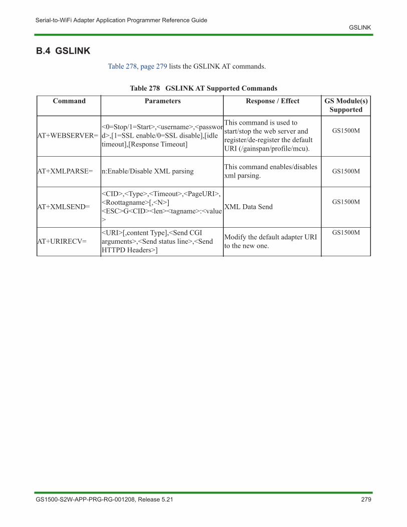
Serial-to-WiFi Adapter Application Programmer Reference GuideGSLINK
B.4 GSLINKTable 278, page 279 lists the GSLINK AT commands.
Table 278 GSLINK AT Supported Commands
Command Parameters Response / Effect GS Module(s) Supported
AT+WEBSERVER=<0=Stop/1=Start>,<username>,<password>,[1=SSL enable/0=SSL disable],[idle timeout],[Response Timeout]
This command is used to start/stop the web server and register/de-register the default URI (/gainspan/profile/mcu).
GS1500M
AT+XMLPARSE= n:Enable/Disable XML parsing This command enables/disables xml parsing. GS1500M
AT+XMLSEND=
<CID>,<Type>,<Timeout>,<PageURI>,<Roottagname>[,<N>] <ESC>G<CID><len><tagname>:<value>
XML Data SendGS1500M
AT+URIRECV=<URI>[,content Type],<Send CGI arguments>,<Send status line>,<Send HTTPD Headers>]
Modify the default adapter URI to the new one.
GS1500M
GS1500-S2W-APP-PRG-RG-001208, Release 5.21 279
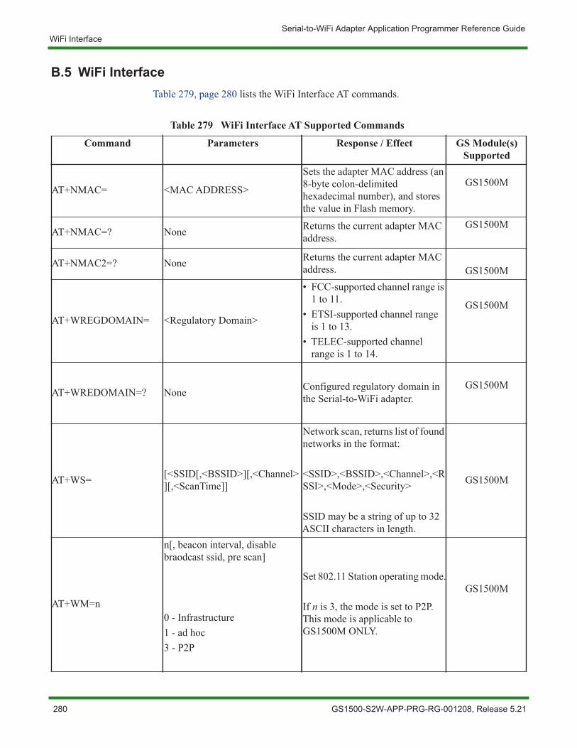
Serial-to-WiFi Adapter Application Programmer Reference GuideWiFi Interface
B.5 WiFi InterfaceTable 279, page 280 lists the WiFi Interface AT commands.
Table 279 WiFi Interface AT Supported Commands
Command Parameters Response / Effect GS Module(s) Supported
AT+NMAC= <MAC ADDRESS>
Sets the adapter MAC address (an 8-byte colon-delimited hexadecimal number), and stores the value in Flash memory.
GS1500M
AT+NMAC=? None Returns the current adapter MAC address.
GS1500M
AT+NMAC2=? None Returns the current adapter MAC address. GS1500M
AT+WREGDOMAIN= <Regulatory Domain>
• FCC-supported channel range is 1 to 11.
• ETSI-supported channel range is 1 to 13.
• TELEC-supported channel range is 1 to 14.
GS1500M
AT+WREDOMAIN=? None Configured regulatory domain in the Serial-to-WiFi adapter.
GS1500M
AT+WS= [<SSID[,<BSSID>][,<Channel>][,<ScanTime]]
Network scan, returns list of found networks in the format:
<SSID>,<BSSID>,<Channel>,<RSSI>,<Mode>,<Security>
SSID may be a string of up to 32 ASCII characters in length.
GS1500M
AT+WM=n
n[, beacon interval, disable braodcast ssid, pre scan]
0 - Infrastructure1 - ad hoc3 - P2P
Set 802.11 Station operating mode.
If n is 3, the mode is set to P2P. This mode is applicable to GS1500M ONLY.
GS1500M
280 GS1500-S2W-APP-PRG-RG-001208, Release 5.21
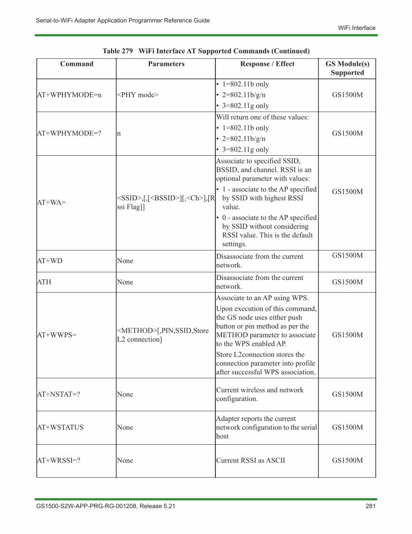
Serial-to-WiFi Adapter Application Programmer Reference GuideWiFi Interface
AT+WPHYMODE=n <PHY mode>• 1=802.11b only• 2=802.11b/g/n• 3=802.11g only
GS1500M
AT+WPHYMODE=? n
Will return one of these values:• 1=802.11b only• 2=802.11b/g/n• 3=802.11g only
GS1500M
AT+WA= <SSID>,[,[<BSSID>][,<Ch>],[Rssi Flag]]
Associate to specified SSID, BSSID, and channel. RSSI is an optional parameter with values:• 1 - associate to the AP specified
by SSID with highest RSSI value.
• 0 - associate to the AP specified by SSID without considering RSSI value. This is the default settings.
GS1500M
AT+WD None Disassociate from the current network.
GS1500M
ATH None Disassociate from the current network. GS1500M
AT+WWPS= <METHOD>[,PIN,SSID,Store L2 connection]
Associate to an AP using WPS. Upon execution of this command, the GS node uses either push button or pin method as per the METHOD parameter to associate to the WPS enabled AP.Store L2connection stores the connection parameter into profile after successful WPS association.
GS1500M
AT+NSTAT=? None Current wireless and network configuration. GS1500M
AT+WSTATUS NoneAdapter reports the current network configuration to the serial host
GS1500M
AT+WRSSI=? None Current RSSI as ASCII GS1500M
Table 279 WiFi Interface AT Supported Commands (Continued)
Command Parameters Response / Effect GS Module(s) Supported
GS1500-S2W-APP-PRG-RG-001208, Release 5.21 281
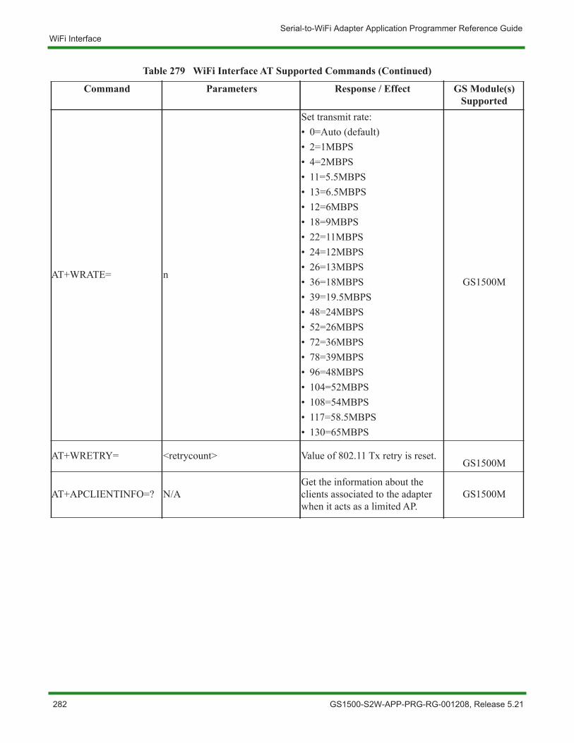
Serial-to-WiFi Adapter Application Programmer Reference GuideWiFi Interface
AT+WRATE= n
Set transmit rate:• 0=Auto (default)• 2=1MBPS• 4=2MBPS• 11=5.5MBPS• 13=6.5MBPS• 12=6MBPS• 18=9MBPS• 22=11MBPS• 24=12MBPS• 26=13MBPS• 36=18MBPS• 39=19.5MBPS• 48=24MBPS• 52=26MBPS• 72=36MBPS• 78=39MBPS• 96=48MBPS• 104=52MBPS• 108=54MBPS• 117=58.5MBPS• 130=65MBPS
GS1500M
AT+WRETRY= <retrycount> Value of 802.11 Tx retry is reset.GS1500M
AT+APCLIENTINFO=? N/AGet the information about the clients associated to the adapter when it acts as a limited AP.
GS1500M
Table 279 WiFi Interface AT Supported Commands (Continued)
Command Parameters Response / Effect GS Module(s) Supported
282 GS1500-S2W-APP-PRG-RG-001208, Release 5.21
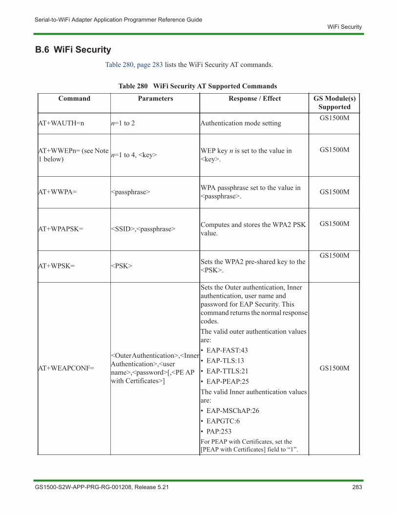
Serial-to-WiFi Adapter Application Programmer Reference GuideWiFi Security
B.6 WiFi SecurityTable 280, page 283 lists the WiFi Security AT commands.
Table 280 WiFi Security AT Supported Commands
Command Parameters Response / Effect GS Module(s) Supported
AT+WAUTH=n n=1 to 2 Authentication mode settingGS1500M
AT+WWEPn= (see Note 1 below) n=1 to 4, <key> WEP key n is set to the value in
<key>.GS1500M
AT+WWPA= <passphrase> WPA passphrase set to the value in <passphrase>. GS1500M
AT+WPAPSK= <SSID>,<passphrase> Computes and stores the WPA2 PSK value.
GS1500M
AT+WPSK= <PSK> Sets the WPA2 pre-shared key to the <PSK>.
GS1500M
AT+WEAPCONF=
<Outer Authentication>,<Inner Authentication>,<user name>,<password>[,<PE AP with Certificates>]
Sets the Outer authentication, Inner authentication, user name and password for EAP Security. This command returns the normal response codes.The valid outer authentication values are:• EAP-FAST:43• EAP-TLS:13• EAP-TTLS:21• EAP-PEAP:25The valid Inner authentication values are:• EAP-MSChAP:26• EAPGTC:6• PAP:253For PEAP with Certificates, set the [PEAP with Certificates] field to “1”.
GS1500M
GS1500-S2W-APP-PRG-RG-001208, Release 5.21 283
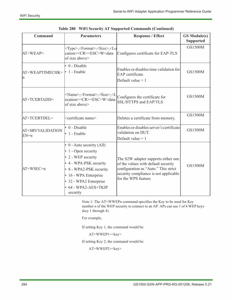
Serial-to-WiFi Adapter Application Programmer Reference GuideWiFi Security
Note 1: The AT+WWEPn command specifies the Key to be used for Key number n of the WEP security to connect to an AP. APs can use 1 of 4 WEP keys (key 1 through 4).
For example,
If setting Key 1, the command would be:
AT+WWEP1=<key>
If setting Key 2, the command would be:
AT+WWEP2=<key>
AT+WEAP=<Type>,<Format>,<Size>,<Location><CR><ESC>W<data of size above>
Configures certificate for EAP-TLSGS1500M
AT+WEAPTIMECHK=n
• 0 - Disable• 1 - Enable Enables or disables time validation for
EAP certificate.Default value = 1
GS1500M
AT+TCERTADD=<Name>,<Format>,<Size>,<Location><CR><ESC>W<data of size above>
Configures the certificate for SSL/HTTPS and EAP/TLS
GS1500M
AT+TCERTDEL= <certificate name> Deletes a certificate from memory.GS1500M
AT+SRVVALIDATIONEN=n
• 0 - Disable• 1 - Enable
Enables or disables server’s certificate validation on DUT.Default value = 1
GS1500M
AT+WSEC=n
• 0 - Auto security (All)• 1 - Open security• 2 - WEP security• 4 - WPA-PSK security• 8 - WPA2-PSK security• 16 - WPA Enterprise• 32 - WPA2 Enterprise• 64 - WPA2-AES+TKIP
security
The S2W adapter supports either one of the values with default security configuration as “Auto.” This strict security compliance is not applicable for the WPS feature.
GS1500M
Table 280 WiFi Security AT Supported Commands (Continued)
Command Parameters Response / Effect GS Module(s) Supported
284 GS1500-S2W-APP-PRG-RG-001208, Release 5.21
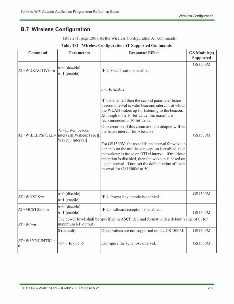
Serial-to-WiFi Adapter Application Programmer Reference GuideWireless Configuration
B.7 Wireless ConfigurationTable 281, page 285 lists the Wireless Configuration AT commands.
Table 281 Wireless Configuration AT Supported Commands
Command Parameters Response/ Effect GS Module(s) Supported
AT+WRXACTIVE=nn=0 (disable)n=1 (enable)
IF 1, 802.11 radio is enabled.GS1500M
AT+WIEEEPSPOLL=<n>[,listen beacon interval][,WakeupType][,Wakeup Interval]
n=1 to enable
If it is enabled then the second parameter listen beacon interval is valid beacons intervals at which the WLAN wakes up for listening to the beacon. Although it’s a 16-bit value, the maximum recommended is 10-bit value.On execution of this command, the adapter will set the listen interval for n beacons.
For GS1500M, the use of listen interval for wakeup depends on the multicast reception is enabled, then the wakeup is based on DTIM interval. If multicast reception is disabled, then the wakeup is based on listen interval. If not, set the default value of listen interval for GS1500M to 50.
GS1500M
AT+WRXPS=nn=0 (disable)n=1 (enable)
IF 1, Power Save mode is enabled.GS1500M
AT+MCSTSET=nn=0 (disable)n=1 (enable)
IF 1, multicast reception is enabled.GS1500M
AT+WP=nThe power level shall be specified in ASCII decimal format with a default value of 0 (for maximum RF output).0 (default) Other values are not supported on the GS1500M. GS1500M
AT+WSYNCINTRL=n <n> 1 to 65535 Configure the sync loss interval. GS1500M
GS1500-S2W-APP-PRG-RG-001208, Release 5.21 285

Serial-to-WiFi Adapter Application Programmer Reference GuideWireless Configuration
NOTE: For GS1500M there is no internal PA and external PA. The default value is 0 (maximum average power is 14 dBm).
286 GS1500-S2W-APP-PRG-RG-001208, Release 5.21
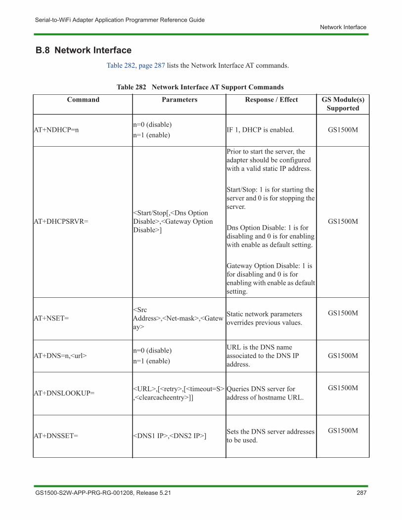
Serial-to-WiFi Adapter Application Programmer Reference GuideNetwork Interface
B.8 Network InterfaceTable 282, page 287 lists the Network Interface AT commands.
Table 282 Network Interface AT Support Commands
Command Parameters Response / Effect GS Module(s) Supported
AT+NDHCP=nn=0 (disable)n=1 (enable)
IF 1, DHCP is enabled. GS1500M
AT+DHCPSRVR=<Start/Stop[,<Dns Option Disable>,<Gateway Option Disable>]
Prior to start the server, the adapter should be configured with a valid static IP address.
Start/Stop: 1 is for starting the server and 0 is for stopping the server.
Dns Option Disable: 1 is for disabling and 0 is for enabling with enable as default setting.
Gateway Option Disable: 1 is for disabling and 0 is for enabling with enable as default setting.
GS1500M
AT+NSET=<Src Address>,<Net-mask>,<Gateway>
Static network parameters overrides previous values.
GS1500M
AT+DNS=n,<url>n=0 (disable)n=1 (enable)
URL is the DNS name associated to the DNS IP address.
GS1500M
AT+DNSLOOKUP= <URL>,[<retry>,[<timeout=S>,<clearcacheentry>]]
Queries DNS server for address of hostname URL.
GS1500M
AT+DNSSET= <DNS1 IP>,<DNS2 IP>] Sets the DNS server addresses to be used.
GS1500M
GS1500-S2W-APP-PRG-RG-001208, Release 5.21 287
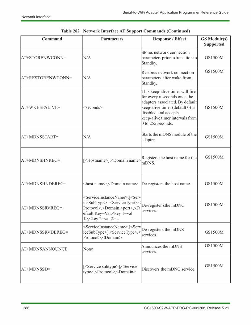
Serial-to-WiFi Adapter Application Programmer Reference GuideNetwork Interface
AT+STORENWCONN= N/AStores network connection parameters prior to transition to Standby.
GS1500M
AT+RESTORENWCONN= N/ARestores network connection parameters after wake from Standby.
GS1500M
AT+WKEEPALIVE= <seconds>
This keep-alive timer will fire for every n seconds once the adapters associated. By default keep-alive timer (default 0) is disabled and accepts keep-alive timer intervals from 0 to 255 seconds.
GS1500M
AT+MDNSSTART= N/A Starts the mDNS module of the adapter. GS1500M
AT+MDNSHNREG= [<Hostname>],<Domain name>Registers the host name for the mDNS.
GS1500M
AT+MDNSHNDEREG= <host name>,<Domain name> De-registers the host name. GS1500M
AT+MDNSSRVREG=
<ServiceInstanceName>,[<ServiceSubType>],<ServiceType>,<Protocol>,<Domain,<port>,<Default Key=Val,<key 1=val 1>,<key 2=val 2>...
De-register sthe mDNC services.
GS1500M
AT+MDNSSRVDEREG=<ServiceInstanceName>,[<ServiceSubType>],<ServiceType>,<Protocol>,<Domain>
De-registers the mDNS services. GS1500M
AT+MDNSANNOUNCE None Announces the mDNS services.
GS1500M
AT+MDNSSD= [<Service subtype>],<Service type>,<Protocol>,<Domain> Discovers the mDNC service.
GS1500M
Table 282 Network Interface AT Support Commands (Continued)
Command Parameters Response / Effect GS Module(s) Supported
288 GS1500-S2W-APP-PRG-RG-001208, Release 5.21
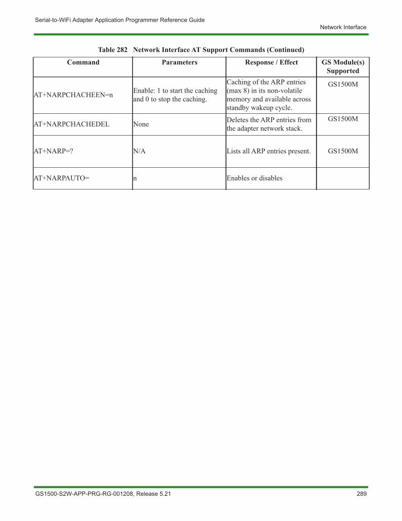
Serial-to-WiFi Adapter Application Programmer Reference GuideNetwork Interface
AT+NARPCHACHEEN=n Enable: 1 to start the caching and 0 to stop the caching.
Caching of the ARP entries (max 8) in its non-volatile memory and available across standby wakeup cycle.
GS1500M
AT+NARPCHACHEDEL None Deletes the ARP entries from the adapter network stack.
GS1500M
AT+NARP=? N/A Lists all ARP entries present. GS1500M
AT+NARPAUTO= n Enables or disables
Table 282 Network Interface AT Support Commands (Continued)
Command Parameters Response / Effect GS Module(s) Supported
GS1500-S2W-APP-PRG-RG-001208, Release 5.21 289
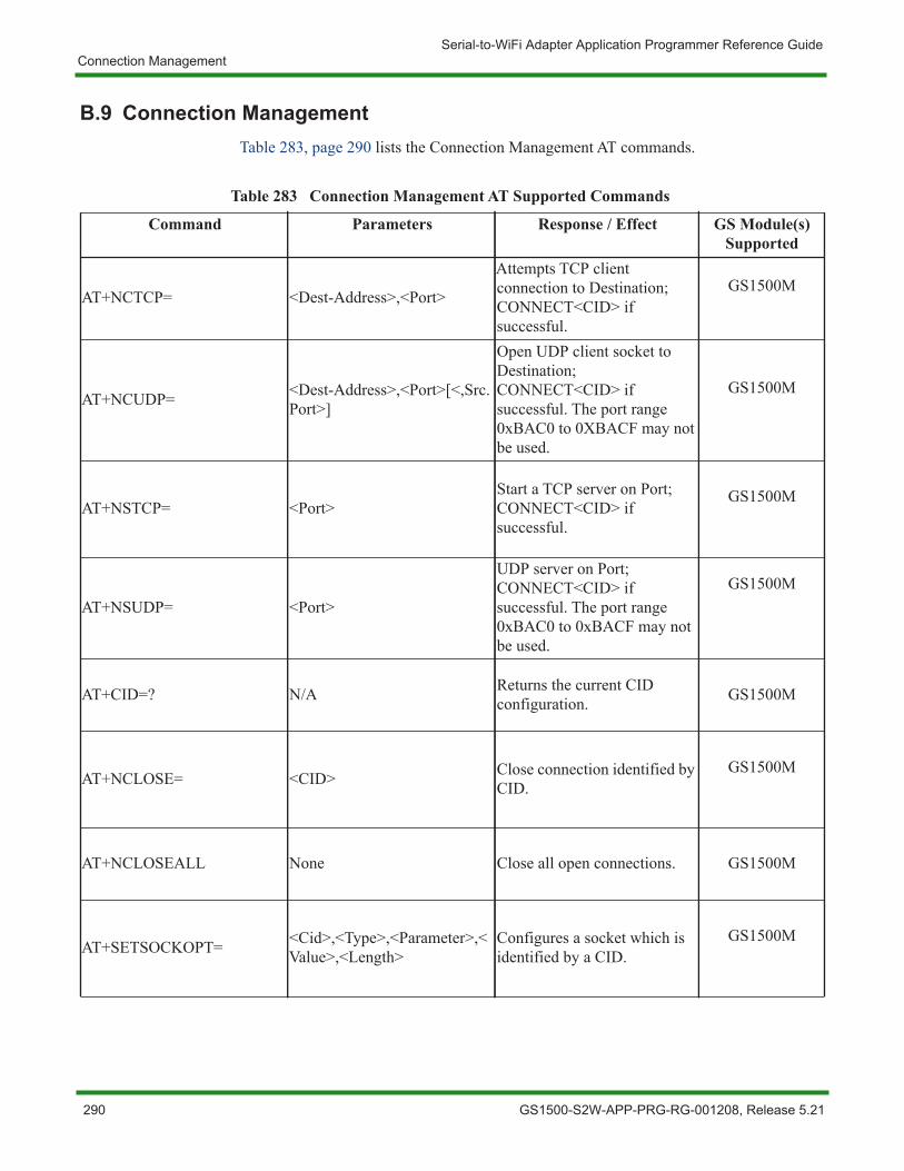
Serial-to-WiFi Adapter Application Programmer Reference GuideConnection Management
B.9 Connection ManagementTable 283, page 290 lists the Connection Management AT commands.
Table 283 Connection Management AT Supported Commands
Command Parameters Response / Effect GS Module(s) Supported
AT+NCTCP= <Dest-Address>,<Port>
Attempts TCP client connection to Destination; CONNECT<CID> if successful.
GS1500M
AT+NCUDP= <Dest-Address>,<Port>[<,Src.Port>]
Open UDP client socket to Destination; CONNECT<CID> if successful. The port range 0xBAC0 to 0XBACF may not be used.
GS1500M
AT+NSTCP= <Port>Start a TCP server on Port; CONNECT<CID> if successful.
GS1500M
AT+NSUDP= <Port>
UDP server on Port; CONNECT<CID> if successful. The port range 0xBAC0 to 0xBACF may not be used.
GS1500M
AT+CID=? N/A Returns the current CID configuration. GS1500M
AT+NCLOSE= <CID> Close connection identified by CID.
GS1500M
AT+NCLOSEALL None Close all open connections. GS1500M
AT+SETSOCKOPT= <Cid>,<Type>,<Parameter>,<Value>,<Length>
Configures a socket which is identified by a CID.
GS1500M
290 GS1500-S2W-APP-PRG-RG-001208, Release 5.21
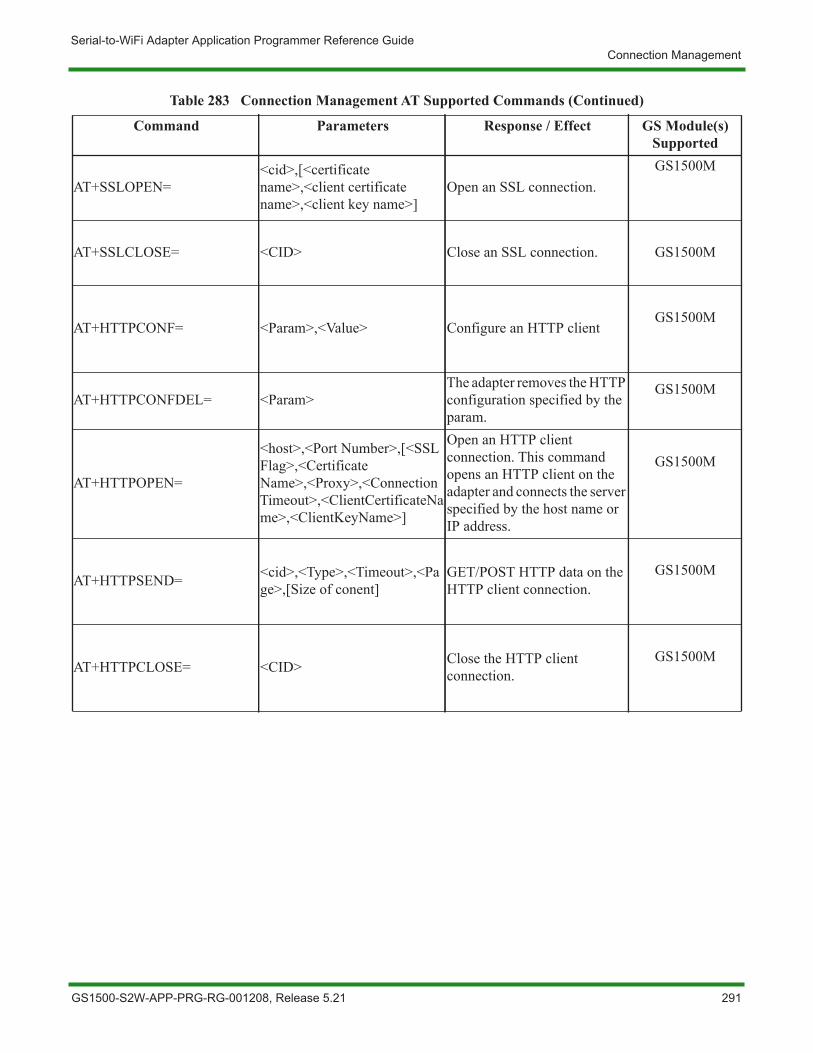
Serial-to-WiFi Adapter Application Programmer Reference GuideConnection Management
AT+SSLOPEN=<cid>,[<certificate name>,<client certificate name>,<client key name>]
Open an SSL connection.GS1500M
AT+SSLCLOSE= <CID> Close an SSL connection. GS1500M
AT+HTTPCONF= <Param>,<Value> Configure an HTTP clientGS1500M
AT+HTTPCONFDEL= <Param>The adapter removes the HTTP configuration specified by the param.
GS1500M
AT+HTTPOPEN=
<host>,<Port Number>,[<SSL Flag>,<Certificate Name>,<Proxy>,<Connection Timeout>,<ClientCertificateName>,<ClientKeyName>]
Open an HTTP client connection. This command opens an HTTP client on the adapter and connects the server specified by the host name or IP address.
GS1500M
AT+HTTPSEND= <cid>,<Type>,<Timeout>,<Page>,[Size of conent]
GET/POST HTTP data on the HTTP client connection.
GS1500M
AT+HTTPCLOSE= <CID> Close the HTTP client connection.
GS1500M
Table 283 Connection Management AT Supported Commands (Continued)
Command Parameters Response / Effect GS Module(s) Supported
GS1500-S2W-APP-PRG-RG-001208, Release 5.21 291

Serial-to-WiFi Adapter Application Programmer Reference GuideConnection Management
AT+NRAW=n
• 0 - Disable• 1 - Enable (NON-SNAP)• 2 - Enable (All)
• 0 - Disables Raw Ethernet frame transmission/reception.
• 1 - Enables Raw Ethernet frames with NON-SNAP 802.2LLC headers
• 2 - Enables all Raw Ethernet frames
GS1500M
AT+APCONF=nEnable: 1 is for limited AP mode and 0 is for station mode, with default value as 0.
NCMAP parameters can be configured using the auto connect.
GS1500M
AT+FACTORYRESTORE None
Restore the limited AP parameters for the NCM auto command to the values present in the factory default section of the adapter.
GS1500M
Table 283 Connection Management AT Supported Commands (Continued)
Command Parameters Response / Effect GS Module(s) Supported
292 GS1500-S2W-APP-PRG-RG-001208, Release 5.21

Serial-to-WiFi Adapter Application Programmer Reference GuidePower Management
B.10 Power ManagementTable 284, page 293 lists the Power Management AT commands.
Table 284 Power Management AT Supported Commands
Command Parameters Response / Effect GS Module(s) Supported
AT+PSDPSLEEP<timeout>,<ALARM1 POL>,<ALARM2 POL>,<Stop SysTicks>
Enable SoC Deep Sleep power saving mode. GS1500M
AT+PSSTBY= <x>[,<DelayTime>,<Alarm1pol.>,<Alarm2pol.>]
Request transition to Standby for x milliseconds.
GS1500M
GS1500-S2W-APP-PRG-RG-001208, Release 5.21 293

Serial-to-WiFi Adapter Application Programmer Reference GuideAuto Connection
B.11 Auto ConnectionTable 285, page 294 lists the Auto Connection AT commands.
Table 285 Auto Connection AT Supported Commands
Command Parameters Response / Effect GS Module(s) Supported
AT+WAUTO= <mode>,<SSID>,<BSSID>,[channel]
Sets WiFi parameters to be used for Auto Connect.
GS1500M
AT+NAUTO=<Type>,<Protocol>,<Destination IP>,<Destination Port>
Sets network parameters to be used for Auto Connect. GS1500M
ATCnn=0 (disable)n=1 (enable)
IF 1, Auto Connect is enabled on next reboot or AT. GS1500M
ATO NoneReturn to a previous Auto Connect sessions; returns an error if no such session exists.
GS1500M
AT+WEBPROV= <user name>,<passwd> Provisioning through web pages.GS1500M
AT+WEBPROVSTOP N/A Stops the web provisioning.GS1500M
AT+WEBLOGOADD= <size> maximum size is 1788 bytes
Adding the Logo that will appear on the web pages used for provisioning. GS1500M
AT+NURIREDIR= <URL> Redirection URL support.GS1500M
294 GS1500-S2W-APP-PRG-RG-001208, Release 5.21
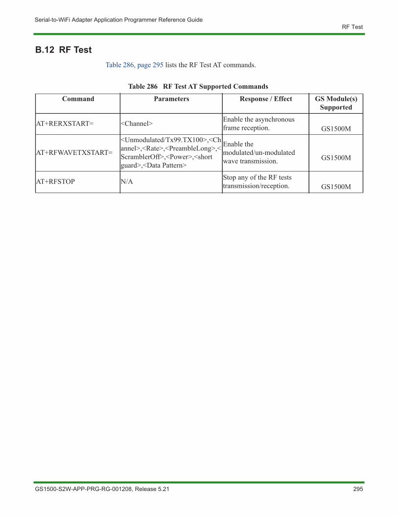
Serial-to-WiFi Adapter Application Programmer Reference GuideRF Test
B.12 RF TestTable 286, page 295 lists the RF Test AT commands.
Table 286 RF Test AT Supported Commands
Command Parameters Response / Effect GS Module(s) Supported
AT+RERXSTART= <Channel> Enable the asynchronous frame reception. GS1500M
AT+RFWAVETXSTART=
<Unmodulated/Tx99.TX100>,<Channel>,<Rate>,<PreambleLong>,<ScramblerOff>,<Power>,<short guard>,<Data Pattern>
Enable the modulated/un-modulated wave transmission. GS1500M
AT+RFSTOP N/A Stop any of the RF tests transmission/reception. GS1500M
GS1500-S2W-APP-PRG-RG-001208, Release 5.21 295
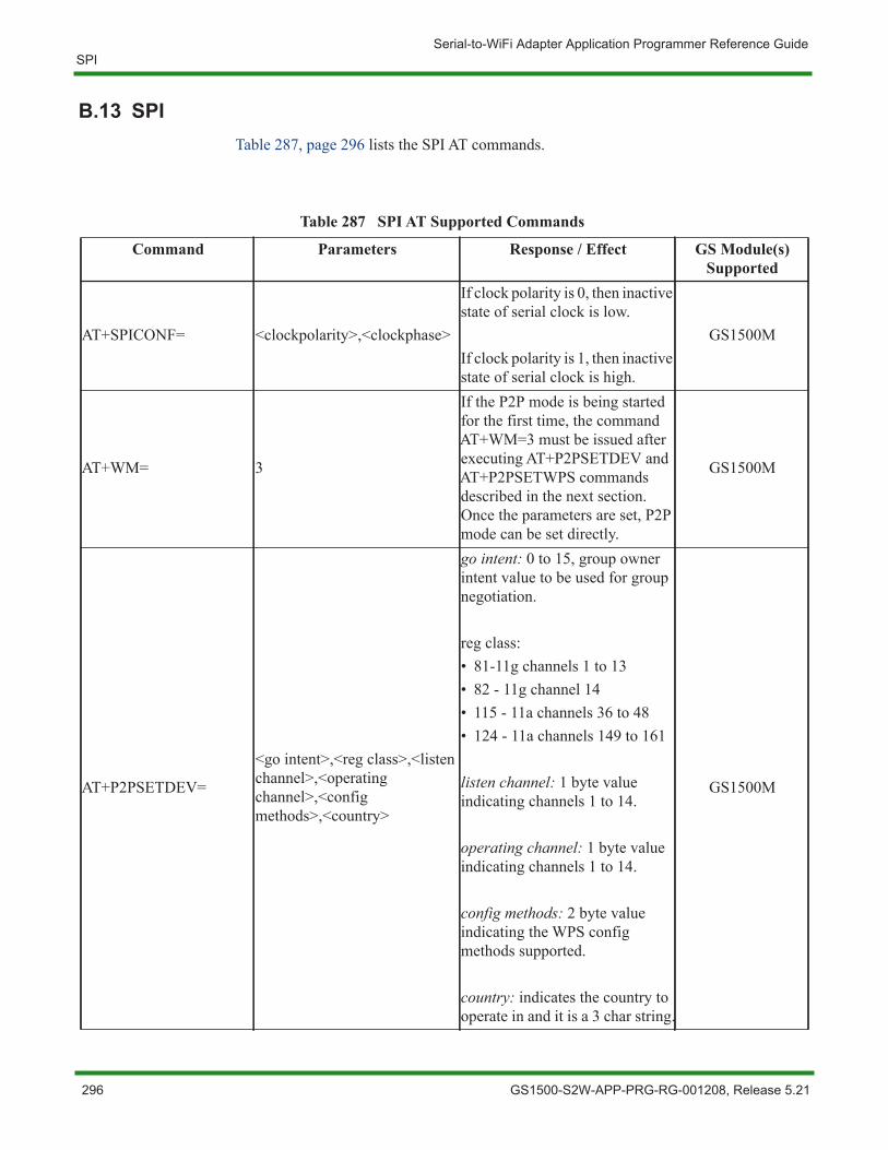
Serial-to-WiFi Adapter Application Programmer Reference GuideSPI
B.13 SPITable 287, page 296 lists the SPI AT commands.
Table 287 SPI AT Supported Commands
Command Parameters Response / Effect GS Module(s) Supported
AT+SPICONF= <clockpolarity>,<clockphase>
If clock polarity is 0, then inactive state of serial clock is low.
If clock polarity is 1, then inactive state of serial clock is high.
GS1500M
AT+WM= 3
If the P2P mode is being started for the first time, the command AT+WM=3 must be issued after executing AT+P2PSETDEV and AT+P2PSETWPS commands described in the next section. Once the parameters are set, P2P mode can be set directly.
GS1500M
AT+P2PSETDEV=
<go intent>,<reg class>,<listen channel>,<operating channel>,<config methods>,<country>
go intent: 0 to 15, group owner intent value to be used for group negotiation.
reg class:• 81-11g channels 1 to 13• 82 - 11g channel 14• 115 - 11a channels 36 to 48• 124 - 11a channels 149 to 161
listen channel: 1 byte value indicating channels 1 to 14.
operating channel: 1 byte value indicating channels 1 to 14.
config methods: 2 byte value indicating the WPS config methods supported.
country: indicates the country to operate in and it is a 3 char string.
GS1500M
296 GS1500-S2W-APP-PRG-RG-001208, Release 5.21
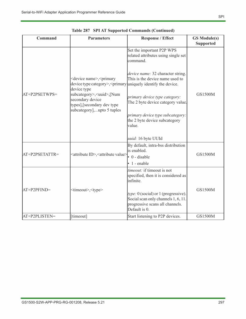
Serial-to-WiFi Adapter Application Programmer Reference GuideSPI
AT+P2PSETWPS=
<device name>,<primary device type category>,<primary device type subcategory>,<uuid>,[Num secondary device types],[secondary dev type subcategory],...upto 5 tuples
Set the important P2P WPS related attributes using single set command.
device name: 32 character string. This is the device name used to uniquely identify the device.
primary device type category: The 2 byte device category value.
primary device type subcategory: the 2 byte device subcategory value.
uuid: 16 byte UUId
GS1500M
AT+P2PSETATTR= <attribute ID>,<attribute value>
By default, intra-bss distribution is enabled.• 0 - disable• 1 - enable
GS1500M
AT+P2PFIND= <timeout>,<type>
timeout: if timeout is not specified, then it is considered as infinite.
type: 0 (social) or 1 (progressive). Social scan only channels 1, 6, 11. progressive scans all channels. Default is 0.
GS1500M
AT+P2PLISTEN= [timeout] Start listening to P2P devices. GS1500M
Table 287 SPI AT Supported Commands (Continued)
Command Parameters Response / Effect GS Module(s) Supported
GS1500-S2W-APP-PRG-RG-001208, Release 5.21 297
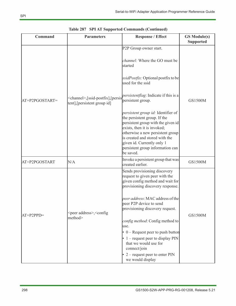
Serial-to-WiFi Adapter Application Programmer Reference GuideSPI
AT+P2PGOSTART= <channel>,[ssid-postfix],[persistent],[persistent group id]
P2P Group owner start.
channel: Where the GO must be started
ssidPostfix: Optional postfix to be used for the ssid
persistentflag: Indicate if this is a persistent group.
persistent group id: Identifier of the persistent group. If the persistent group with the given id exists, then it is invoked; otherwise a new persistent group is created and stored with the given id. Currently only 1 persistent group information can be saved.
GS1500M
AT+P2PGOSTART N/A Invoke a persistent group that was created earlier. GS1500M
AT+P2PPD= <peer address>,<config method>
Sends provisioning discovery request to given peer with the given config method and wait for provisioning discovery response.
peer address: MAC address of the peer P2P device to send provisioning discovery request.
config method: Config method to use.• 0 – Request peer to push button• 1 – request peer to display PIN
that we would use for connect/join
• 2 – request peer to enter PIN we would display
GS1500M
Table 287 SPI AT Supported Commands (Continued)
Command Parameters Response / Effect GS Module(s) Supported
298 GS1500-S2W-APP-PRG-RG-001208, Release 5.21
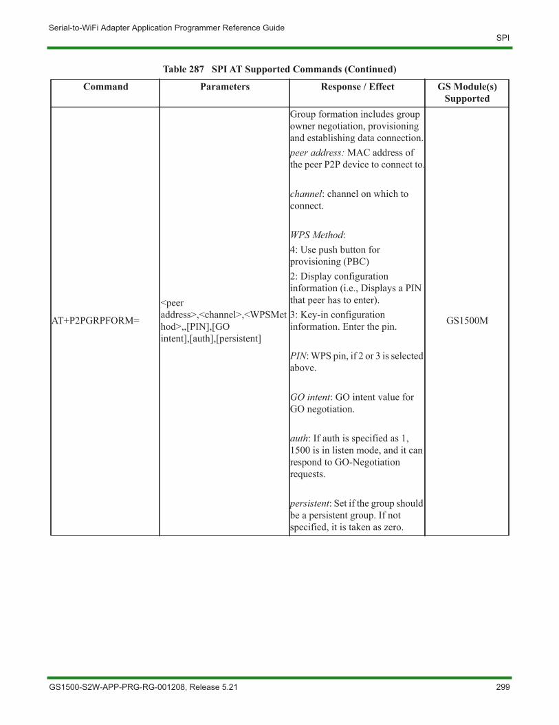
Serial-to-WiFi Adapter Application Programmer Reference GuideSPI
AT+P2PGRPFORM=
<peer address>,<channel>,<WPSMethod>,,[PIN],[GO intent],[auth],[persistent]
Group formation includes group owner negotiation, provisioning and establishing data connection.peer address: MAC address of the peer P2P device to connect to.
channel: channel on which to connect.
WPS Method:4: Use push button for provisioning (PBC)2: Display configuration information (i.e., Displays a PIN that peer has to enter).3: Key-in configuration information. Enter the pin.
PIN: WPS pin, if 2 or 3 is selected above.
GO intent: GO intent value for GO negotiation.
auth: If auth is specified as 1, 1500 is in listen mode, and it can respond to GO-Negotiation requests.
persistent: Set if the group should be a persistent group. If not specified, it is taken as zero.
GS1500M
Table 287 SPI AT Supported Commands (Continued)
Command Parameters Response / Effect GS Module(s) Supported
GS1500-S2W-APP-PRG-RG-001208, Release 5.21 299
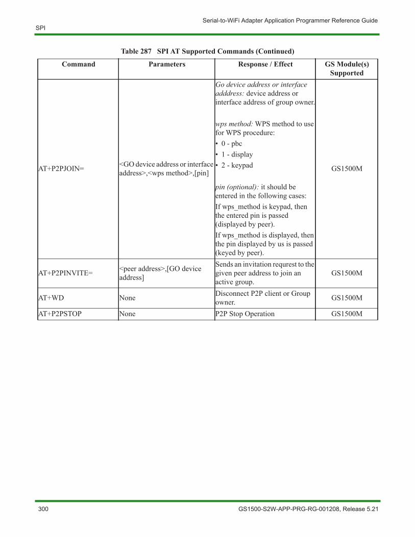
Serial-to-WiFi Adapter Application Programmer Reference GuideSPI
AT+P2PJOIN= <GO device address or interface address>,<wps method>,[pin]
Go device address or interface adddress: device address or interface address of group owner.
wps method: WPS method to use for WPS procedure:• 0 - pbc• 1 - display• 2 - keypad
pin (optional): it should be entered in the following cases:If wps_method is keypad, then the entered pin is passed (displayed by peer).If wps_method is displayed, then the pin displayed by us is passed (keyed by peer).
GS1500M
AT+P2PINVITE= <peer address>,[GO device address]
Sends an invitation requrest to the given peer address to join an active group.
GS1500M
AT+WD None Disconnect P2P client or Group owner. GS1500M
AT+P2PSTOP None P2P Stop Operation GS1500M
Table 287 SPI AT Supported Commands (Continued)
Command Parameters Response / Effect GS Module(s) Supported
300 GS1500-S2W-APP-PRG-RG-001208, Release 5.21
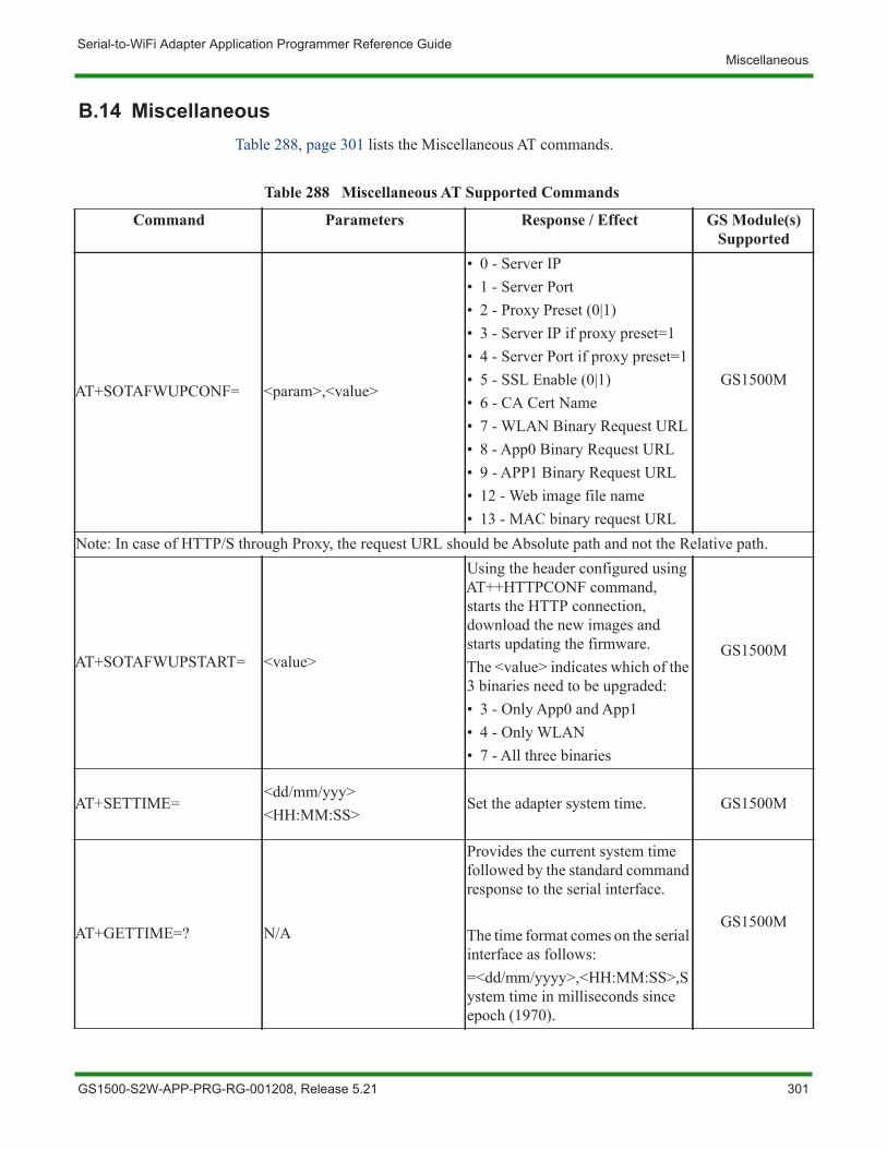
Serial-to-WiFi Adapter Application Programmer Reference GuideMiscellaneous
B.14 MiscellaneousTable 288, page 301 lists the Miscellaneous AT commands.
Table 288 Miscellaneous AT Supported Commands
Command Parameters Response / Effect GS Module(s) Supported
AT+SOTAFWUPCONF= <param>,<value>
• 0 - Server IP• 1 - Server Port• 2 - Proxy Preset (0|1)• 3 - Server IP if proxy preset=1• 4 - Server Port if proxy preset=1• 5 - SSL Enable (0|1)• 6 - CA Cert Name• 7 - WLAN Binary Request URL• 8 - App0 Binary Request URL• 9 - APP1 Binary Request URL• 12 - Web image file name• 13 - MAC binary request URL
GS1500M
Note: In case of HTTP/S through Proxy, the request URL should be Absolute path and not the Relative path.
AT+SOTAFWUPSTART= <value>
Using the header configured using AT++HTTPCONF command, starts the HTTP connection, download the new images and starts updating the firmware.The <value> indicates which of the 3 binaries need to be upgraded:• 3 - Only App0 and App1• 4 - Only WLAN• 7 - All three binaries
GS1500M
AT+SETTIME=<dd/mm/yyy><HH:MM:SS>
Set the adapter system time. GS1500M
AT+GETTIME=? N/A
Provides the current system time followed by the standard command response to the serial interface.
The time format comes on the serial interface as follows:=<dd/mm/yyyy>,<HH:MM:SS>,System time in milliseconds since epoch (1970).
GS1500M
GS1500-S2W-APP-PRG-RG-001208, Release 5.21 301
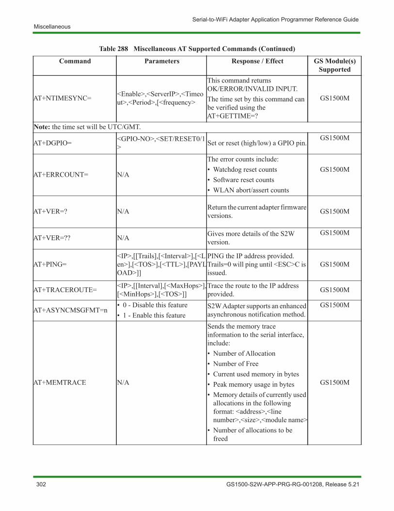
Serial-to-WiFi Adapter Application Programmer Reference GuideMiscellaneous
AT+NTIMESYNC= <Enable>,<ServerIP>,<Timeout>,<Period>,[<frequency>
This command returns OK/ERROR/INVALID INPUT.The time set by this command can be verified using the AT+GETTIME=?
GS1500M
Note: the time set will be UTC/GMT.
AT+DGPIO= <GPIO-NO>,<SET/RESET0/1> Set or reset (high/low) a GPIO pin.
GS1500M
AT+ERRCOUNT= N/A
The error counts include:• Watchdog reset counts• Software reset counts• WLAN abort/assert counts
GS1500M
AT+VER=? N/A Return the current adapter firmware versions. GS1500M
AT+VER=?? N/A Gives more details of the S2W version.
GS1500M
AT+PING=<IP>,[[Trails],[<Interval>],[<Len>],[<TOS>],[<TTL>],[PAYLOAD>]]
PING the IP address provided. Trails=0 will ping until <ESC>C is issued.
GS1500M
AT+TRACEROUTE= <IP>,[[Interval],[<MaxHops>],[<MinHops>],[<TOS>]]
Trace the route to the IP address provided. GS1500M
AT+ASYNCMSGFMT=n• 0 - Disable this feature• 1 - Enable this feature
S2W Adapter supports an enhanced asynchronous notification method.
GS1500M
AT+MEMTRACE N/A
Sends the memory trace information to the serial interface, include:• Number of Allocation• Number of Free• Current used memory in bytes• Peak memory usage in bytes• Memory details of currently used
allocations in the following format: <address>,<line number>,<size>,<module name>
• Number of allocations to be freed
GS1500M
Table 288 Miscellaneous AT Supported Commands (Continued)
Command Parameters Response / Effect GS Module(s) Supported
302 GS1500-S2W-APP-PRG-RG-001208, Release 5.21
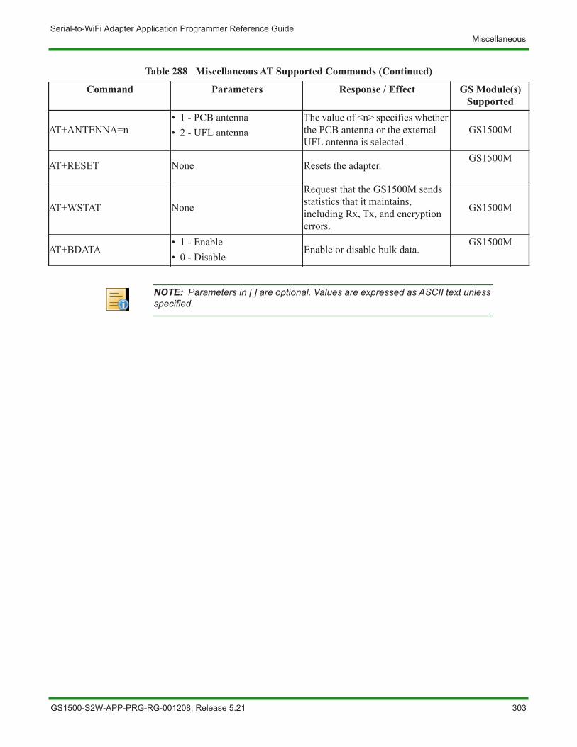
Serial-to-WiFi Adapter Application Programmer Reference GuideMiscellaneous
AT+ANTENNA=n• 1 - PCB antenna• 2 - UFL antenna
The value of <n> specifies whether the PCB antenna or the external UFL antenna is selected.
GS1500M
AT+RESET None Resets the adapter.GS1500M
AT+WSTAT None
Request that the GS1500M sends statistics that it maintains, including Rx, Tx, and encryption errors.
GS1500M
AT+BDATA• 1 - Enable• 0 - Disable
Enable or disable bulk data.GS1500M
Table 288 Miscellaneous AT Supported Commands (Continued)
Command Parameters Response / Effect GS Module(s) Supported
NOTE: Parameters in [ ] are optional. Values are expressed as ASCII text unless specified.
GS1500-S2W-APP-PRG-RG-001208, Release 5.21 303
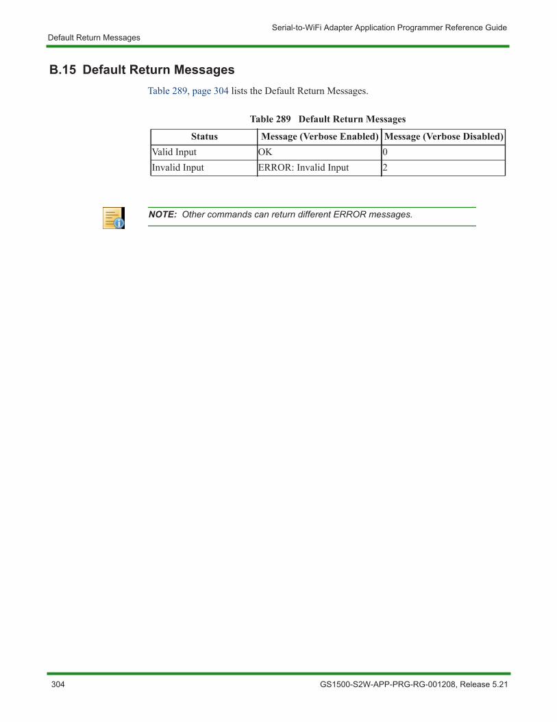
Serial-to-WiFi Adapter Application Programmer Reference GuideDefault Return Messages
B.15 Default Return MessagesTable 289, page 304 lists the Default Return Messages.
Table 289 Default Return Messages
Status Message (Verbose Enabled) Message (Verbose Disabled)Valid Input OK 0Invalid Input ERROR: Invalid Input 2
NOTE: Other commands can return different ERROR messages.
304 GS1500-S2W-APP-PRG-RG-001208, Release 5.21
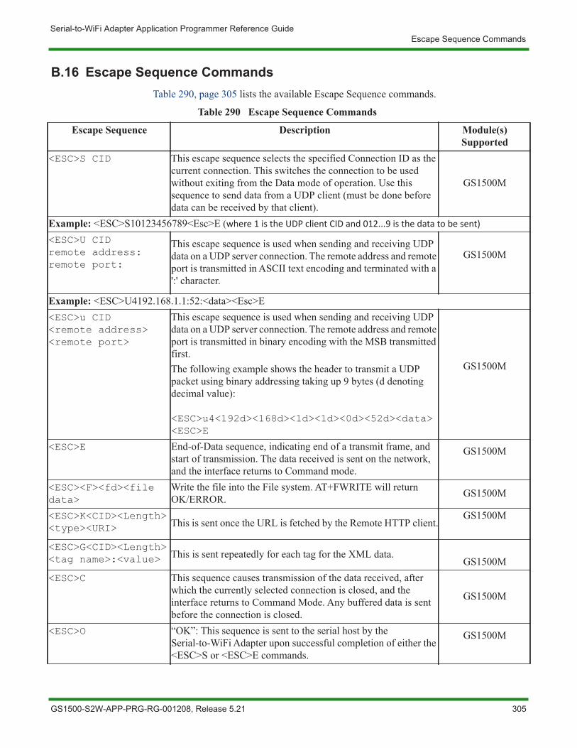
Serial-to-WiFi Adapter Application Programmer Reference GuideEscape Sequence Commands
B.16 Escape Sequence CommandsTable 290, page 305 lists the available Escape Sequence commands.
Table 290 Escape Sequence Commands
Escape Sequence Description Module(s) Supported
<ESC>S CID This escape sequence selects the specified Connection ID as the current connection. This switches the connection to be used without exiting from the Data mode of operation. Use this sequence to send data from a UDP client (must be done before data can be received by that client).
GS1500M
Example: <ESC>S10123456789<Esc>E (where 1 is the UDP client CID and 012...9 is the data to be sent)
<ESC>U CIDremote address:remote port:
This escape sequence is used when sending and receiving UDP data on a UDP server connection. The remote address and remote port is transmitted in ASCII text encoding and terminated with a ':' character.
GS1500M
Example: <ESC>U4192.168.1.1:52:<data><Esc>E<ESC>u CID<remote address><remote port>
This escape sequence is used when sending and receiving UDP data on a UDP server connection. The remote address and remote port is transmitted in binary encoding with the MSB transmitted first.The following example shows the header to transmit a UDP packet using binary addressing taking up 9 bytes (d denoting decimal value):
<ESC>u4<192d><168d><1d><1d><0d><52d><data><ESC>E
GS1500M
<ESC>E End-of-Data sequence, indicating end of a transmit frame, and start of transmission. The data received is sent on the network, and the interface returns to Command mode.
GS1500M
<ESC><F><fd><file data>
Write the file into the File system. AT+FWRITE will return OK/ERROR. GS1500M
<ESC>K<CID><Length><type><URI> This is sent once the URL is fetched by the Remote HTTP client.
GS1500M
<ESC>G<CID><Length><tag name>:<value> This is sent repeatedly for each tag for the XML data.
GS1500M<ESC>C This sequence causes transmission of the data received, after
which the currently selected connection is closed, and the interface returns to Command Mode. Any buffered data is sent before the connection is closed.
GS1500M
<ESC>O “OK”: This sequence is sent to the serial host by the Serial-to-WiFi Adapter upon successful completion of either the <ESC>S or <ESC>E commands.
GS1500M
GS1500-S2W-APP-PRG-RG-001208, Release 5.21 305
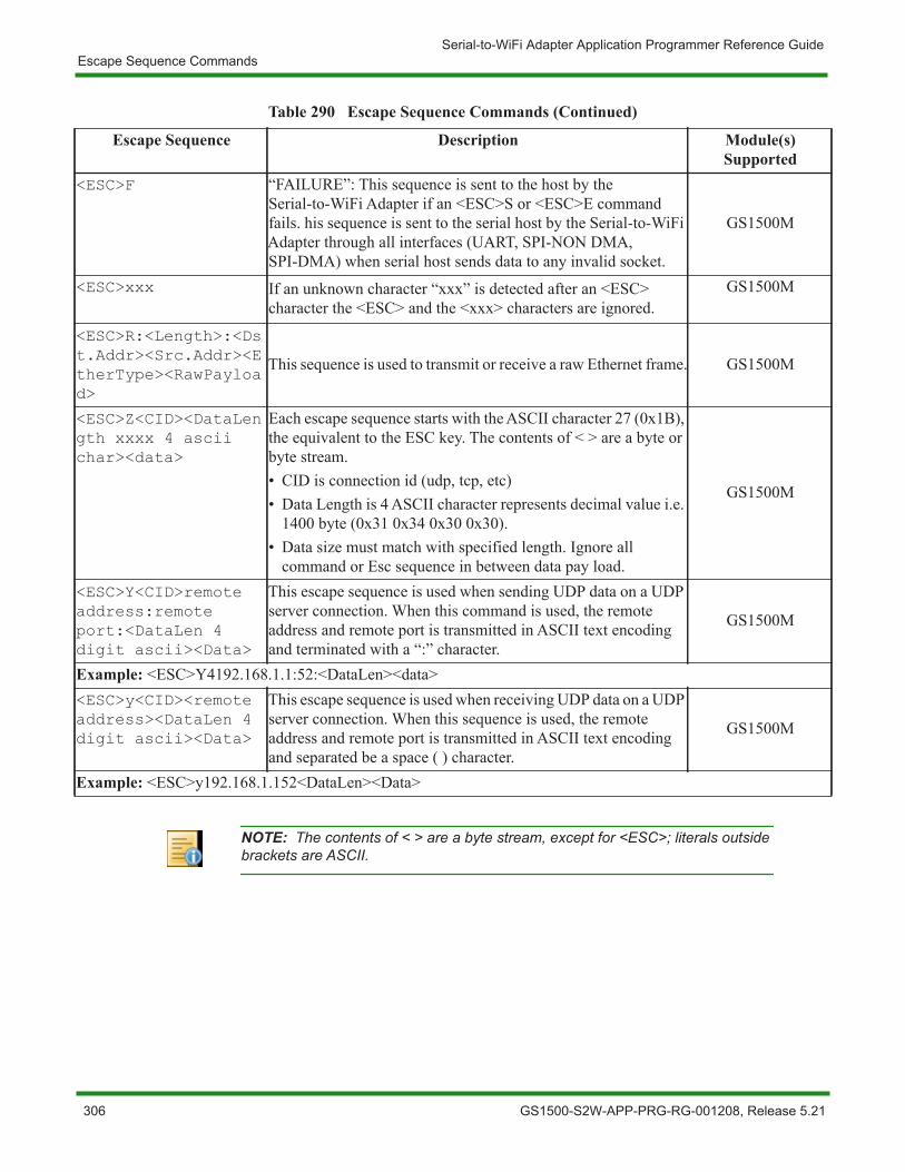
Serial-to-WiFi Adapter Application Programmer Reference GuideEscape Sequence Commands
<ESC>F “FAILURE”: This sequence is sent to the host by the Serial-to-WiFi Adapter if an <ESC>S or <ESC>E command fails. his sequence is sent to the serial host by the Serial-to-WiFi Adapter through all interfaces (UART, SPI-NON DMA, SPI-DMA) when serial host sends data to any invalid socket.
GS1500M
<ESC>xxx If an unknown character “xxx” is detected after an <ESC> character the <ESC> and the <xxx> characters are ignored.
GS1500M
<ESC>R:<Length>:<Dst.Addr><Src.Addr><EtherType><RawPayload>
This sequence is used to transmit or receive a raw Ethernet frame. GS1500M
<ESC>Z<CID><DataLength xxxx 4 ascii char><data>
Each escape sequence starts with the ASCII character 27 (0x1B), the equivalent to the ESC key. The contents of < > are a byte or byte stream.• CID is connection id (udp, tcp, etc)• Data Length is 4 ASCII character represents decimal value i.e.
1400 byte (0x31 0x34 0x30 0x30).• Data size must match with specified length. Ignore all
command or Esc sequence in between data pay load.
GS1500M
<ESC>Y<CID>remote address:remote port:<DataLen 4 digit ascii><Data>
This escape sequence is used when sending UDP data on a UDP server connection. When this command is used, the remote address and remote port is transmitted in ASCII text encoding and terminated with a “:” character.
GS1500M
Example: <ESC>Y4192.168.1.1:52:<DataLen><data><ESC>y<CID><remote address><DataLen 4 digit ascii><Data>
This escape sequence is used when receiving UDP data on a UDP server connection. When this sequence is used, the remote address and remote port is transmitted in ASCII text encoding and separated be a space ( ) character.
GS1500M
Example: <ESC>y192.168.1.152<DataLen><Data>
Table 290 Escape Sequence Commands (Continued)
Escape Sequence Description Module(s) Supported
NOTE: The contents of < > are a byte stream, except for <ESC>; literals outside brackets are ASCII.
306 GS1500-S2W-APP-PRG-RG-001208, Release 5.21