Embed Size (px)
Citation preview
Series Circuit Isolating Transformers
Series circuit airfield lighting isolating transformers feature plug-in connectors to simplify installation and maintenance
FeaturesThere are two methods of connecting the transformers to the primary series circuit: a) by using cables of predetermined lengths to which appropriate plugs and sockets have been moulded, or b) by using connector kits which can be fitted quickly to the cables on site. The advantage of the latter method is that cable can be despatched to site in bulk lengths and cut as required.
Connection of the secondary circuit is via a socket to each light which is fitted with a short plug lead supplied as part of the light fitting assembly. A separate extension lead is available where the transformer cannot be directly connected to the light fitting.
The use of these FAA approved transformers facilitates the isolation and testing of series circuits in which faults may exist or be suspected.
Whichever method of installation is used, it is advisable to provide in the cable trench an earth wire or counterpoise which can be used to earth each transformer secondary.
It will also serve to limit the effect of lightning strikes and reduce the effect of differences in soil resistivity along the cable route, especially where cables enter a duct from a cable trench. Where termites or other insects are liable to attack cables and transformers, a shielded cable should be used. This precaution will not only protect the cable core from such attacks but will also reduce the effects of sheath tracking. This form of cable failure
may occur where unshielded cables buried in the ground pass through areas where a change of soil resistivity occurs e.g. entering a cable duct or passing through a rocky area.
The shielding of the cable must be maintained at earth potential throughout the length of the ring circuit. In these cases, short unshielded leads with plugs or sockets at one end are used for connecting the transformer, whilst the free ends of these leads are jointed to the terminations of the shielded cables either side of the transformers.
Care must be taken to provide a continuity conductor between the shielding tapes of the cables. If the transformers are to be placed in a metal enclosure, the shielded cables can be ‘made-off’ in suitable glands which will ensure the continuity of the shielding tape on the cable.
LED transformers Special low wattage transformers that have their secondary winding stepped down to match the maximum rated current for a light emitting diode.
SISO
T/Re
v 1
2014
UK: +44 (0) 1942 68 5555 | USA: 001 (239) 985-9406
www.atgairports.com [email protected] [email protected]
UK: +44 (0) 1942 68 5555 | USA: 001 (239) 985-9406
www.atgairports.com [email protected] [email protected]
Series CircuitIsolationgTransformers
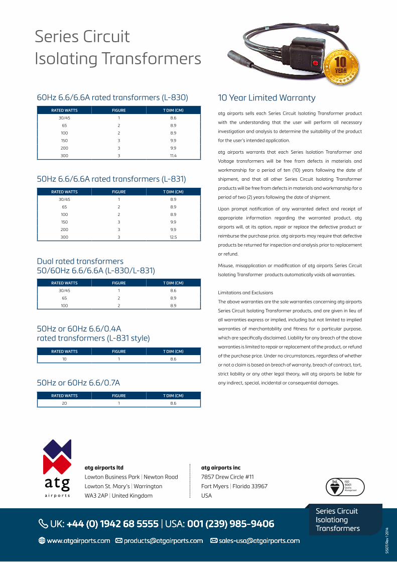
Transformer dimensional data
Series Circuit Isolating Transformers
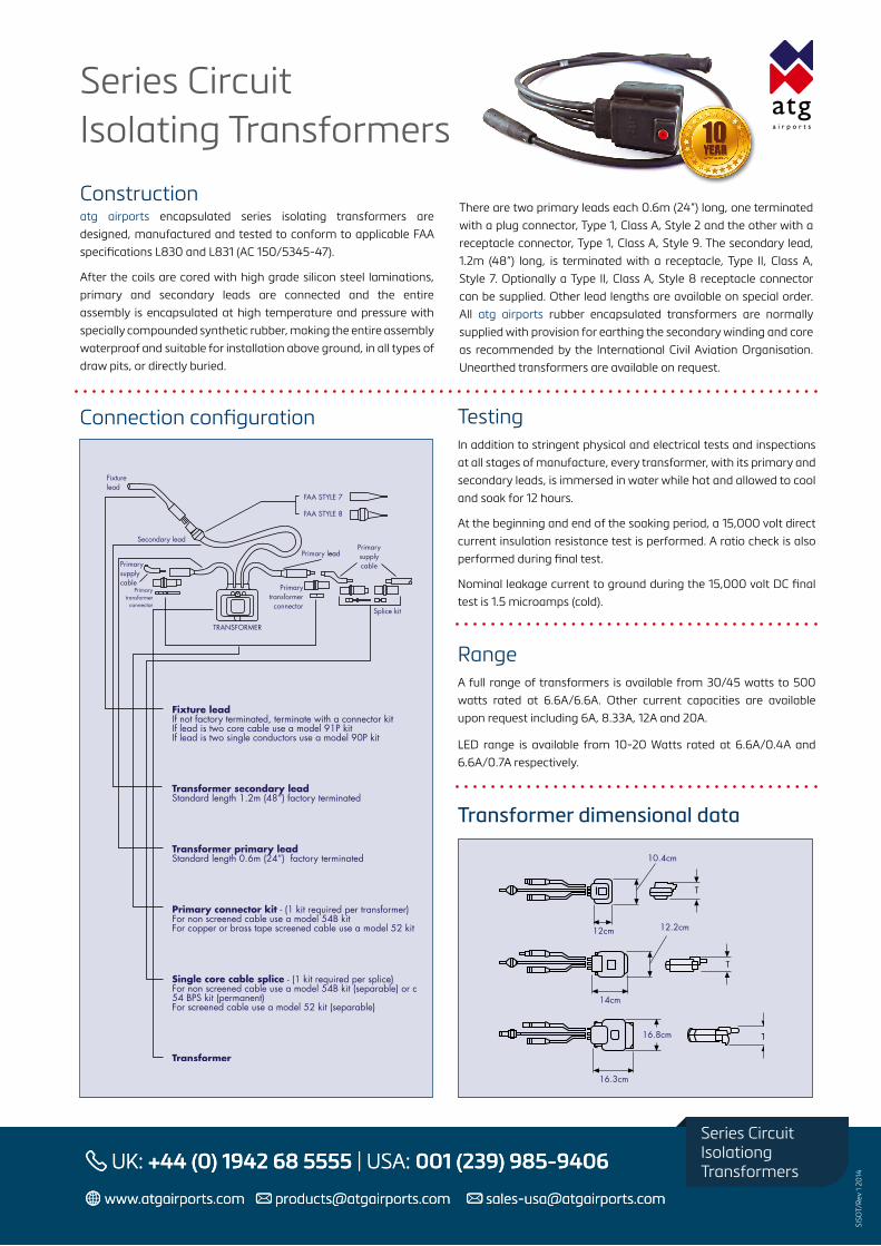
Connection configuration
Constructionatg airports encapsulated series isolating transformers are designed, manufactured and tested to conform to applicable FAA specifications L830 and L831 (AC 150/5345-47).
After the coils are cored with high grade silicon steel laminations, primary and secondary leads are connected and the entire assembly is encapsulated at high temperature and pressure with specially compounded synthetic rubber, making the entire assembly waterproof and suitable for installation above ground, in all types of draw pits, or directly buried.
There are two primary leads each 0.6m (24”) long, one terminated with a plug connector, Type 1, Class A, Style 2 and the other with a receptacle connector, Type 1, Class A, Style 9. The secondary lead, 1.2m (48”) long, is terminated with a receptacle, Type II, Class A, Style 7. Optionally a Type II, Class A, Style 8 receptacle connector can be supplied. Other lead lengths are available on special order. All atg airports rubber encapsulated transformers are normally supplied with provision for earthing the secondary winding and core as recommended by the International Civil Aviation Organisation. Unearthed transformers are available on request.
Testing In addition to stringent physical and electrical tests and inspections at all stages of manufacture, every transformer, with its primary and secondary leads, is immersed in water while hot and allowed to cool and soak for 12 hours.
At the beginning and end of the soaking period, a 15,000 volt direct current insulation resistance test is performed. A ratio check is also performed during final test.
Nominal leakage current to ground during the 15,000 volt DC final test is 1.5 microamps (cold).
RangeA full range of transformers is available from 30/45 watts to 500 watts rated at 6.6A/6.6A. Other current capacities are available upon request including 6A, 8.33A, 12A and 20A.
LED range is available from 10-20 Watts rated at 6.6A/0.4A and 6.6A/0.7A respectively.
SISO
T/Re
v 1
2014
UK: +44 (0) 1942 68 5555 | USA: 001 (239) 985-9406
www.atgairports.com [email protected] [email protected]
UK: +44 (0) 1942 68 5555 | USA: 001 (239) 985-9406
www.atgairports.com [email protected] [email protected]
Series CircuitIsolationgTransformers
SISO
T/Re
v 1
2014
UK: +44 (0) 1942 68 5555 | USA: 001 (239) 985-9406
www.atgairports.com [email protected] [email protected]
UK: +44 (0) 1942 68 5555 | USA: 001 (239) 985-9406
www.atgairports.com [email protected] [email protected]
Series CircuitIsolationgTransformers
60Hz 6.6/6.6A rated transformers (L-830)RATED WATTS FIGURE T DIM (CM)
30/45 1 8.6
65 2 8.9
100 2 8.9
150 3 9.9
200 3 9.9
300 3 11.4
50Hz 6.6/6.6A rated transformers (L-831)RATED WATTS FIGURE T DIM (CM)
30/45 1 8.9
65 2 8.9
100 2 8.9
150 3 9.9
200 3 9.9
300 3 12.5
Dual rated transformers50/60Hz 6.6/6.6A (L-830/L-831)
RATED WATTS FIGURE T DIM (CM)
30/45 1 8.6
65 2 8.9
100 2 8.9
50Hz or 60Hz 6.6/0.4Arated transformers (L-831 style)
RATED WATTS FIGURE T DIM (CM)
10 1 8.6
50Hz or 60Hz 6.6/0.7ARATED WATTS FIGURE T DIM (CM)
20 1 8.6
10 Year Limited Warranty
atg airports sells each Series Circuit Isolating Transformer product
with the understanding that the user will perform all necessary
investigation and analysis to determine the suitability of the product
for the user’s intended application.
atg airports warrants that each Series Isolation Transformer and
Voltage transformers will be free from defects in materials and
workmanship for a period of ten (10) years following the date of
shipment, and that all other Series Circuit Isolating Transformer
products will be free from defects in materials and workmanship for a
period of two (2) years following the date of shipment.
Upon prompt notification of any warranted defect and receipt of
appropriate information regarding the warranted product, atg
airports will, at its option, repair or replace the defective product or
reimburse the purchase price. atg airports may require that defective
products be returned for inspection and analysis prior to replacement
or refund.
Misuse, misapplication or modification of atg airports Series Circuit
Isolating Transformer products automatically voids all warranties.
Limitations and Exclusions
The above warranties are the sole warranties concerning atg airports
Series Circuit Isolating Transformer products, and are given in lieu of
all warranties express or implied, including but not limited to implied
warranties of merchantability and fitness for a particular purpose,
which are specifically disclaimed. Liability for any breach of the above
warranties is limited to repair or replacement of the product, or refund
of the purchase price. Under no circumstances, regardless of whether
or not a claim is based on breach of warranty, breach of contract, tort,
strict liability or any other legal theory, will atg airports be liable for
any indirect, special, incidental or consequential damages.
Series Circuit Isolating Transformers
SISO
T/Re
v 1
2014
UK: +44 (0) 1942 68 5555 | USA: 001 (239) 985-9406
www.atgairports.com [email protected] [email protected]
UK: +44 (0) 1942 68 5555 | USA: 001 (239) 985-9406
www.atgairports.com [email protected] [email protected]
Series CircuitIsolationgTransformers
atg airports ltd
Lowton Business Park | Newton Road
Lowton St. Mary’s | Warrington
WA3 2AP | United Kingdom
atg airports inc
7857 Drew Circle #11
Fort Myers | Florida 33967
USA