Embed Size (px)
Citation preview
MIYAWAKI · English Edition50
Steam Traps
SERIES G Pumping Trap
*Maintenance space
Dimensions
Body MaterialWeight
H H1 H2 H3 H4 D W E*
mm in mm in mm in mm in mm in mm in mm in mm in kg lb
495 19.5 70 2.8 154 6.1 270 10.6 413 16.3 325 12.8 280 11.0 >165 >6.5Ductile Cast Iron FCD450
comparable withEN-GJS-450-10 (EN-JS1040)
50 110
Connection Max. AllowablePressure PMA
Max. AllowableTemperature TMA
Max. OperatingPressure PMO
Max. OperatingTemperature TMO
InletCondensate
OutletCondensate
InletMotive Medium
VentingOutlet MPa psig °C °F MPa psig °C °F
1¨ Rc 1¨ Rc ½¨ Rc ½¨ Rc 1,6 232 220 428 1,05 152 185 365
Condensate amount Length
kg/h lb mm in
100 220 290 11.4 200 440 580 22.8 400 880 1150 45.3 600 1.320 1730 68.1 800 1.760 2300 90.61000 2.220 2870 113.01200 2.640 3450 135.81300 2.860 3730 146.9
Recommended standard receiver tank dimensions: Diameter: 8¨/ DN200Length: 580 mm / 22.8 inchIf a receiver tank is not available, a standard pipe (size 3¨/ DN80) can be used as condensate reservoir.Use the following pipe length:
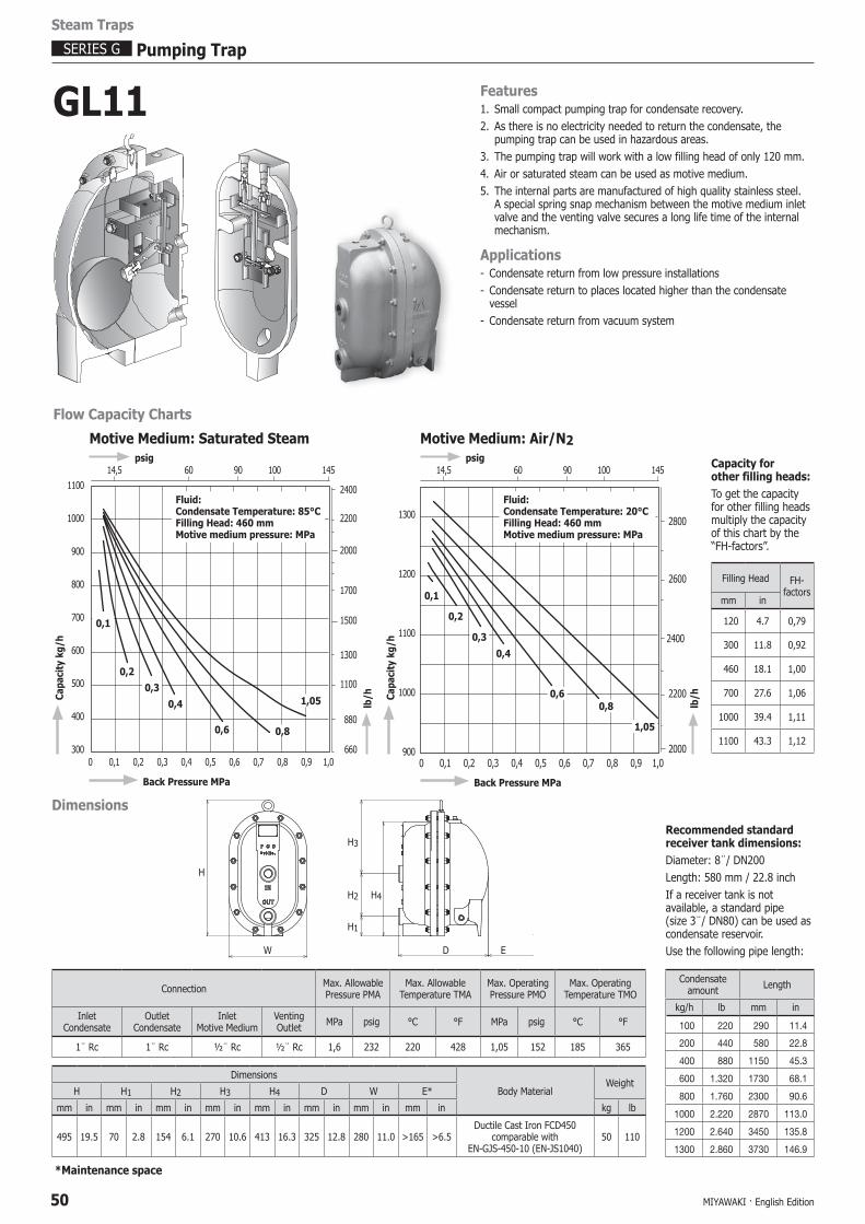
Features 1. Small compact pumping trap for condensate recovery.2. As there is no electricity needed to return the condensate, the
pumping trap can be used in hazardous areas.3. The pumping trap will work with a low filling head of only 120 mm.4. Air or saturated steam can be used as motive medium.5. The internal parts are manufactured of high quality stainless steel.
A special spring snap mechanism between the motive medium inlet valve and the venting valve secures a long life time of the internal mechanism.
Applications- Condensate return from low pressure installations- Condensate return to places located higher than the condensate
vessel- Condensate return from vacuum system
GL11
Filling Head FH-factors
mm in
120 4.7 0,79
300 11.8 0,92
460 18.1 1,00
700 27.6 1,06
1000 39.4 1,11
1100 43.3 1,12
Capacity for other filling heads: To get the capacity for other filling heads multiply the capacity of this chart by the“FH-factors”.
Motive Medium: Saturated Steam
Fluid:Condensate Temperature: 85°CFilling Head: 460 mmMotive medium pressure: MPa
1100
1000
900
800
700
600
500
400
3000 0,1 0,2 0,3 0,4 0,5 0,6 0,7 0,8 0,9 1,0
Cap
acit
y kg
/h
Back Pressure MPa
psig
0,1
0,20,3
0,4
0,6 0,8
1,05
14,5 60 90 100 145
lb/
h
660
2400
2200
1700
1300
1100
880
2000
1500
Motive Medium: Air/N2
Flow Capacity Charts
Dimensions
H1
H2
H3
H4
EDW
H
14,5 60 90 100 145 psig
Fluid:Condensate Temperature: 20°CFilling Head: 460 mmMotive medium pressure: MPa
1300
1200
1100
1000
9000 0,1 0,2 0,3 0,4 0,5 0,6 0,7 0,8 0,9 1,0
Back Pressure MPa
0,1
0,2
0,3
0,4
0,60,8
1,05
lb/
h
2000
2800
2600
2200
2400
Cap
acit
y kg
/h
MIYAWAKI · English Edition 51
Steam Traps
Pumping Trap SERIES G
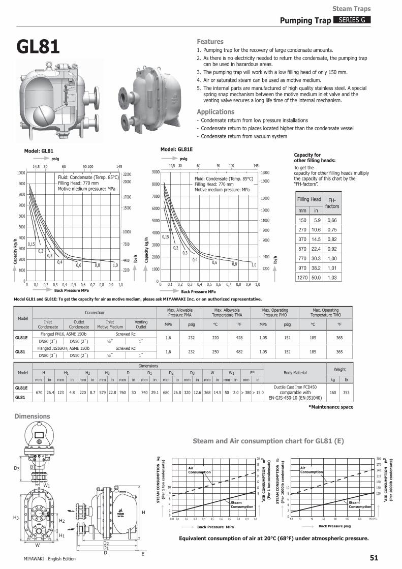
GL81 Features 1. Pumping trap for the recovery of large condensate amounts.2. As there is no electricity needed to return the condensate, the pumping trap
can be used in hazardous areas.3. The pumping trap will work with a low filling head of only 150 mm.4. Air or saturated steam can be used as motive medium.5. The internal parts are manufactured of high quality stainless steel. A special
spring snap mechanism between the motive medium inlet valve and the venting valve secures a long life time of the internal mechanism.
Applications- Condensate return from low pressure installations- Condensate return to places located higher than the condensate vessel- Condensate return from vacuum system
1000
2000
3000
4000
5000
6000
7000
8000
9000
1.0MPa0.8MPa0.6MPa
0.4MPa
0.3MPa
0.2MPa
0
1000014,5 30 60 90 100 145
2200
4400
7500
10000
20000
15000
22000
17000
0 0,40,20,1 0,3 0,5 0,6 0,7 0,8 0,9 1,0
0,15
1,00,80,60,4
0,30,2
Fluid: Condensate (Temp. 85°C)Filling Head: 770 mmMotive medium pressure: MPa
psig
lb/
h
Back Pressure MPa
C
apac
ity
kg/h
1000
2000
3000
4000
5000
6000
7000
8000
9000
1,00,80,60,4
0,30,2
0,15
00 0,1 0,40,2 0,3 0,5 0,6 0,90,7 0,8 1,0
Fluid: Condensate (Temp. 85°C)Filling Head: 770 mmMotive medium pressure: MPa
Back Pressure MPa
Cap
acit
y kg
/h
lb/
h
psig
15000
19800
13000
18000
11000
4400
7000
9000
145100906014,5
2200
Filling Head FH-factors
mm in
150 5.9 0,66
270 10.6 0,75
370 14.5 0,82
570 22.4 0,92
770 30.3 1,00
970 38.2 1,01
1270 50.0 1,03
Capacity forother filling heads: To get thecapacity for other filling heads multiply the capacity of this chart by the“FH-factors”.
Dimensions
ModelConnection Max. Allowable
Pressure PMAMax. Allowable
Temperature TMAMax. OperatingPressure PMO
Max. OperatingTemperature TMO
InletCondensate
OutletCondensate
InletMotive Medium
VentingOutlet MPa psig °C °F MPa psig °C °F
GL81EFlanged PN16, ASME 150lb Screwed Rc
1,6 232 220 428 1,05 152 185 365DN80 (3¨) DN50 (2¨) ½¨ 1¨
GL81Flanged JIS16KFF, ASME 150lb Screwed Rc
1,6 232 250 482 1,05 152 185 365DN80 (3¨) DN50 (2¨) ½¨ 1¨
*Maintenance space
Model
Dimensions
Body MaterialWeight
H H1 H2 H3 D D1 D2 D3 W W1 E*
mm in mm in mm in mm in mm in mm in mm in mm in mm in mm in mm in kg lb
GL81E670 26.4 123 4.8 220 8.7 579 22.8 760 30 740 29.1 680 26.8 320 12.6 368 14.5 50 2.0 > 380 > 15.0
Ductile Cast Iron FCD450comparable with
EN-GJS-450-10 (EN-JS1040)160 353
GL81
Model: GL81 Model: GL81E
Model GL81 and GL81E: To get the capacity for air as motive medium, please ask MIYAWAKI Inc. or an authorized representative.
30
Steam and Air consumption chart for GL81 (E)
Equivalent consumption of air at 20°C (68°F) under atmospheric pressure.
*STEA
M C
ON
SUM
PTI
ON
lb
(Per
10
00
lb c
onde
nsa
te)
AIR
CO
NSU
MP
TIO
N
ft3
(Per
10
00
lb c
onde
nsa
te)
2
4
8
6
10
0
150
180
210
240
270
300
120
4.4 20 40 60 80 100 120 140 145
* AIR
CO
NSU
MP
TIO
N
m3
(Per
1 t
on c
onde
nsa
te)
STEA
M C
ON
SUM
PTI
ON
kg
(Per
1 t
on c
onde
nsa
te)
8
10
12
14
16
18
20
2
4
8
6
10
0
Back Pressure MPa
0,03 0,1 0,2 0,3 0,4 0,5 0,6 0,7 0,8 0,9 1,0
AirConsumption
W1
W
H1
H2H3
D3
DD1D2
H
E
AirConsumption
SteamConsumption
SteamConsumption
Back Pressure psig
MIYAWAKI · English Edition52
Steam Traps
SERIES G Pumping Trap
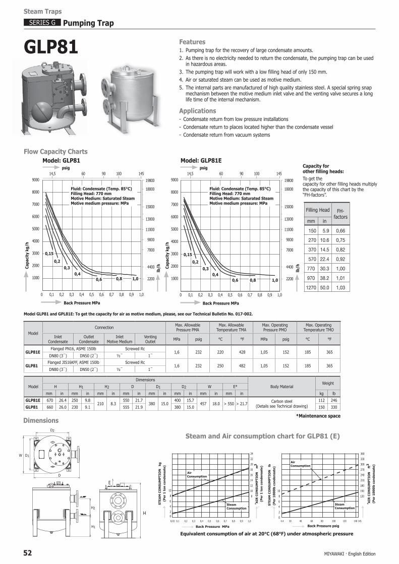
GLP81
Dimensions
W
D
D1
D2
H1
H2 H
E
ModelConnection Max. Allowable
Pressure PMAMax. Allowable
Temperature TMAMax. OperatingPressure PMO
Max. OperatingTemperature TMO
InletCondensate
OutletCondensate
InletMotive Medium
VentingOutlet MPa psig °C °F MPa psig °C °F
GLP81EFlanged PN16, ASME 150lb Screwed Rc
1,6 232 220 428 1,05 152 185 365DN80 (3¨) DN50 (2¨) ½¨ 1¨
GLP81Flanged JIS16KFF, ASME 150lb Screwed Rc
1,6 232 250 482 1,05 152 185 365DN80 (3¨) DN50 (2¨) ½¨ 1¨
*Maintenance space
Model
Dimensions
Body MaterialWeight
H H1 H2 D D1 D2 W E*
mm in mm in mm in mm in mm in mm in mm in mm in kg lb
GLP81E 670 26.4 250 9.8210 8.3
550 21.7380 15.0
400 15.7457 18.0 > 550 > 21.7 Carbon steel
(Details see Technical drawing)112 246
GLP81 660 26.0 230 9.1 555 21.9 380 15.0 150 330
Filling Head FH-factors
mm in
150 5.9 0,66
270 10.6 0,75
370 14.5 0,82
570 22.4 0,92
770 30.3 1,00
970 38.2 1,01
1270 50.0 1,03
Capacity forother filling heads: To get thecapacity for other filling heads multiply the capacity of this chart by the“FH-factors”.
lb/
h
9000
8000
7000
6000
5000
4000
3000
2000
1000
0 0,1 0,2 0,3 0,4 0,5 0,6 0,7 0,8 0,9 1,0
Cap
acit
y kg
/h
Back Pressure MPa
14,5 60 90 100 145 psig
Model: GLP81E
15000
19800
13000
18000
11000
2200
4400
7000
9000
0,15
0,20,3
0,40,6 0,8 1,0
Fluid: Condensate (Temp. 85°C)Filling Head: 770 mmMotive Medium: Saturated SteamMotive medium pressure: MPa
Flow Capacity ChartsModel: GLP81
9000
8000
7000
6000
5000
4000
3000
2000
1000
0 0,1 0,2 0,3 0,4 0,5 0,6 0,7 0,8 0,9 1,0
Cap
acit
y kg
/h
Back Pressure MPa
0,15
0,20,3
0,40,6 0,8 1,0
14,5 60 90 100 145 psig
lb/
h
19800
13000
18000
11000
2200
4400
7000
9000
15000
Fluid: Condensate (Temp. 85°C)Filling Head: 770 mmMotive Medium: Saturated SteamMotive medium pressure: MPa
Model GLP81 and GPL81E: To get the capacity for air as motive medium, please, see our Technical Bulletin No. 017-002.
Features 1. Pumping trap for the recovery of large condensate amounts.2. As there is no electricity needed to return the condensate, the pumping trap can be used
in hazardous areas.3. The pumping trap will work with a low filling head of only 150 mm.4. Air or saturated steam can be used as motive medium.5. The internal parts are manufactured of high quality stainless steel. A special spring snap
mechanism between the motive medium inlet valve and the venting valve secures a long life time of the internal mechanism.
Applications- Condensate return from low pressure installations- Condensate return to places located higher than the condensate vessel- Condensate return from vacuum systems
Steam and Air consumption chart for GLP81 (E)
Equivalent consumption of air at 20°C (68°F) under atmospheric pressure
*STEA
M C
ON
SUM
PTI
ON
lb
(Per
10
00
lb c
onde
nsa
te)
AIR
CO
NSU
MP
TIO
N
ft3
(Per
10
00
lb c
onde
nsa
te)
SteamConsumption
AirConsumption
2
4
8
6
10
0
150
180
210
240
270
300
330
360
120
4.4 20 40 60 80 100 120 140 145
*
AirConsumption
SteamConsumption
AIR
CO
NSU
MP
TIO
N
m3
(Per
1 t
on c
onde
nsa
te)
STEA
M C
ON
SUM
PTI
ON
kg
(Per
1 t
on c
onde
nsa
te)
8
10
12
14
16
18
20
22
24
2
4
8
6
10
0
Back Pressure MPa
0,03 0,1 0,2 0,3 0,4 0,5 0,6 0,7 0,8 0,9 1,0
Back Pressure psig
MIYAWAKI · English Edition 53
Steam Traps
Pumping Trap SERIES G
➡
➡
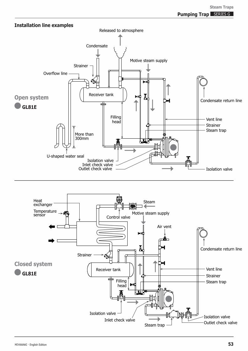
Released to atmosphere
Vent lineStrainer
Inlet check valveIsolation valve
Outlet check valve
More than300mm
U-shaped water seal
Receiver tankCondensate return line
Steam trap
Strainer
Isolation valve
Condensate
Motive steam supply
Heat
Temperaturesensor
exchanger
Control valveMotive steam supply
Condensate return line
Steam
Fillinghead
Fillinghead
Receiver tank
Inlet check valve
Isolation valve
Outlet check valveIsolation valve
Steam trap
Air vent
Vent line
StrainerSteam trap
Strainer
Overflow line
Installation line examples
Open system
GL81E
Closed system
GL81E
MIYAWAKI · English Edition54
Steam Traps
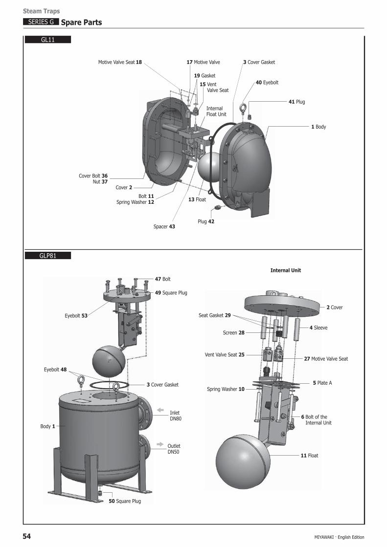
SERIES G Spare Parts
GL11
GLP81
Motive Valve Seat 18 17 Motive Valve
19 Gasket
15 Vent Valve Seat
3 Cover Gasket
40 Eyebolt
41 Plug
1 Body
Cover Bolt 36 Nut 37
Cover 2
Bolt 11Spring Washer 12
Spacer 43
13 Float
Plug 42
InternalFloat Unit
50 Square Plug
3 Cover Gasket
47 Bolt
49 Square Plug
InletDN80
OutletDN50
Eyebolt 48
Eyebolt 53
Body 1
5 Plate A
27 Motive Valve Seat
Screen 28
Seat Gasket 29
4 Sleeve
Vent Valve Seat 25
2 Cover
11 Float
6 Bolt of the Internal Unit
Spring Washer 10
Internal Unit

MIYAWAKI · English Edition 55
GL81
Plug 55
Cover 2 52 Eyebolt 5 Cover Gasket 54 Plug 53 Eyebolt
50 Bolt 1 BodyInternal unitFloat 12Nut 51
Internal unit32 Seat Gasket
28 Vent Valve Seat
Cover 2
Screen 31
Motive Valve Seat 30
Spring Washer 39
Bolt 7
Internal unit
Steam Traps
Spare Parts SERIES G