Embed Size (px)
Citation preview
Session Six: Lightning Protection for Equipment on MV Feeders
Earthing, Lightning & Surge Protection Conference – IDC Technologies 1
Session Six: Lightning Protection for Equipment on MV feeders
WJD van Schalkwyk and M. du Preez*
Chief Engineer, *Engineer Eskom Distribution, North Western Region, Eskom Centre, PO Box 356,
120 Henry Street, Bloemfontein, 9300.
Abstract This paper presents the influence of lighting on MV feeders supplying small power users (400/230V). Attention is given to insulation failures leading to poor power quality. In order to minimize power interruptions, lightning related trips are reduced mainly by minimizing MV equipment failure. Examples of arc quenching are also studied.
Key Words. 300 kV BIL, LTS, arc quenching, lightning, fuses.
Introduction In order to minimize distribution (11 & 22 kV) feeder breaker operations during lightning storms, the feeder was designed at an insulation level (BIL) of 300 kV. The line insulator has a BIL of 150 kV. A section of the wood pole is used to add another 150kV, totalling to a 300 kV BIL. It is also possible that the wood path can assist with arc quench up to 20 A [1]. Though the wood path is an advantage for indirect strokes, it resulted in severe wood splitting due to direct strokes. In some cases the conductors fall to lower levels and become dangerous to humans and animals. Unfortunately, the higher the BIL, the higher the amplitude of the injected travelling waves on the feeders. Numerous fuse failures as well as transformer failures occurred during lightning storms. This was taken care off by developing lightning proof fuses, drop-out line surge arresters and Combi units as shown in Figure 1
Figure 1: Combi unit (A), lightning proof fuse (B) and drop-out line surge arrester (C).
(C)
Session Six: Lightning Protection for Equipment on MV Feeders
Earthing, Lightning & Surge Protection Conference – IDC Technologies 2
1. ENHANCING FEEDER PERFORMANCE
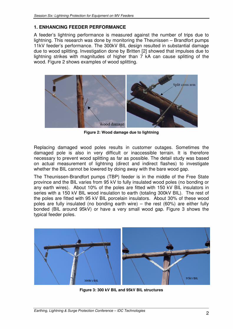
A feeder’s lightning performance is measured against the number of trips due to lightning. This research was done by monitoring the Theunissen – Brandfort pumps 11kV feeder’s performance. The 300kV BIL design resulted in substantial damage due to wood splitting. Investigation done by Britten [2] showed that impulses due to lightning strikes with magnitudes of higher than 7 kA can cause splitting of the wood. Figure 2 shows examples of wood splitting.
Figure 2: Wood damage due to lightning
Replacing damaged wood poles results in customer outages. Sometimes the damaged pole is also in very difficult or inaccessible terrain. It is therefore necessary to prevent wood splitting as far as possible. The detail study was based on actual measurement of lightning (direct and indirect flashes) to investigate whether the BIL cannot be lowered by doing away with the bare wood gap.
The Theunissen-Brandfort pumps (TBP) feeder is in the middle of the Free State province and the BIL varies from 95 kV to fully insulated wood poles (no bonding or any earth wires). About 10% of the poles are fitted with 150 kV BIL insulators in series with a 150 kV BIL wood insulation to earth (totaling 300kV BIL). The rest of the poles are fitted with 95 kV BIL porcelain insulators. About 30% of these wood poles are fully insulated (no bonding earth wire) – the rest (60%) are either fully bonded (BIL around 95kV) or have a very small wood gap. Figure 3 shows the typical feeder poles.
Figure 3: 300 kV BIL and 95kV BIL structures
Session Six: Lightning Protection for Equipment on MV Feeders
Earthing, Lightning & Surge Protection Conference – IDC Technologies 3
1.1 Measurement Equipment and Setup
1.1.1 Power Frequency Loggers:
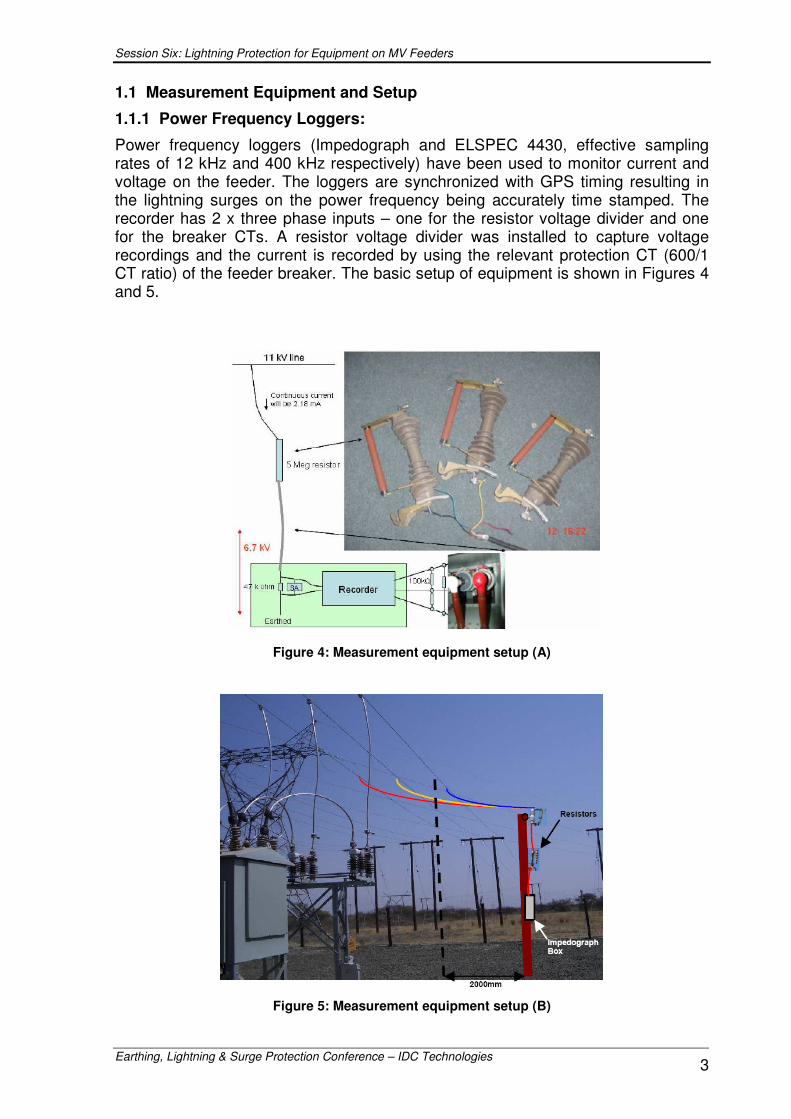
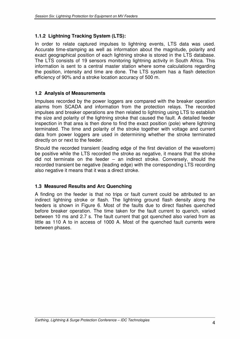
Power frequency loggers (Impedograph and ELSPEC 4430, effective sampling rates of 12 kHz and 400 kHz respectively) have been used to monitor current and voltage on the feeder. The loggers are synchronized with GPS timing resulting in the lightning surges on the power frequency being accurately time stamped. The recorder has 2 x three phase inputs – one for the resistor voltage divider and one for the breaker CTs. A resistor voltage divider was installed to capture voltage recordings and the current is recorded by using the relevant protection CT (600/1 CT ratio) of the feeder breaker. The basic setup of equipment is shown in Figures 4 and 5.
Figure 4: Measurement equipment setup (A)
Figure 5: Measurement equipment setup (B)
Session Six: Lightning Protection for Equipment on MV Feeders
Earthing, Lightning & Surge Protection Conference – IDC Technologies 4
1.1.2 Lightning Tracking System (LTS):
In order to relate captured impulses to lightning events, LTS data was used. Accurate time-stamping as well as information about the magnitude, polarity and exact geographical position of each lightning stroke is stored in the LTS database. The LTS consists of 19 sensors monitoring lightning activity in South Africa. This information is sent to a central master station where some calculations regarding the position, intensity and time are done. The LTS system has a flash detection efficiency of 90% and a stroke location accuracy of 500 m.
1.2 Analysis of Measurements
Impulses recorded by the power loggers are compared with the breaker operation alarms from SCADA and information from the protection relays. The recorded impulses and breaker operations are then related to lightning using LTS to establish the size and polarity of the lightning stroke that caused the fault. A detailed feeder inspection in that area is then done to find the exact position (pole) where lightning terminated. The time and polarity of the stroke together with voltage and current data from power loggers are used in determining whether the stroke terminated directly on or next to the feeder.
Should the recorded transient (leading edge of the first deviation of the waveform) be positive while the LTS recorded the stroke as negative, it means that the stroke did not terminate on the feeder – an indirect stroke. Conversely, should the recorded transient be negative (leading edge) with the corresponding LTS recording also negative it means that it was a direct stroke.
1.3 Measured Results and Arc Quenching
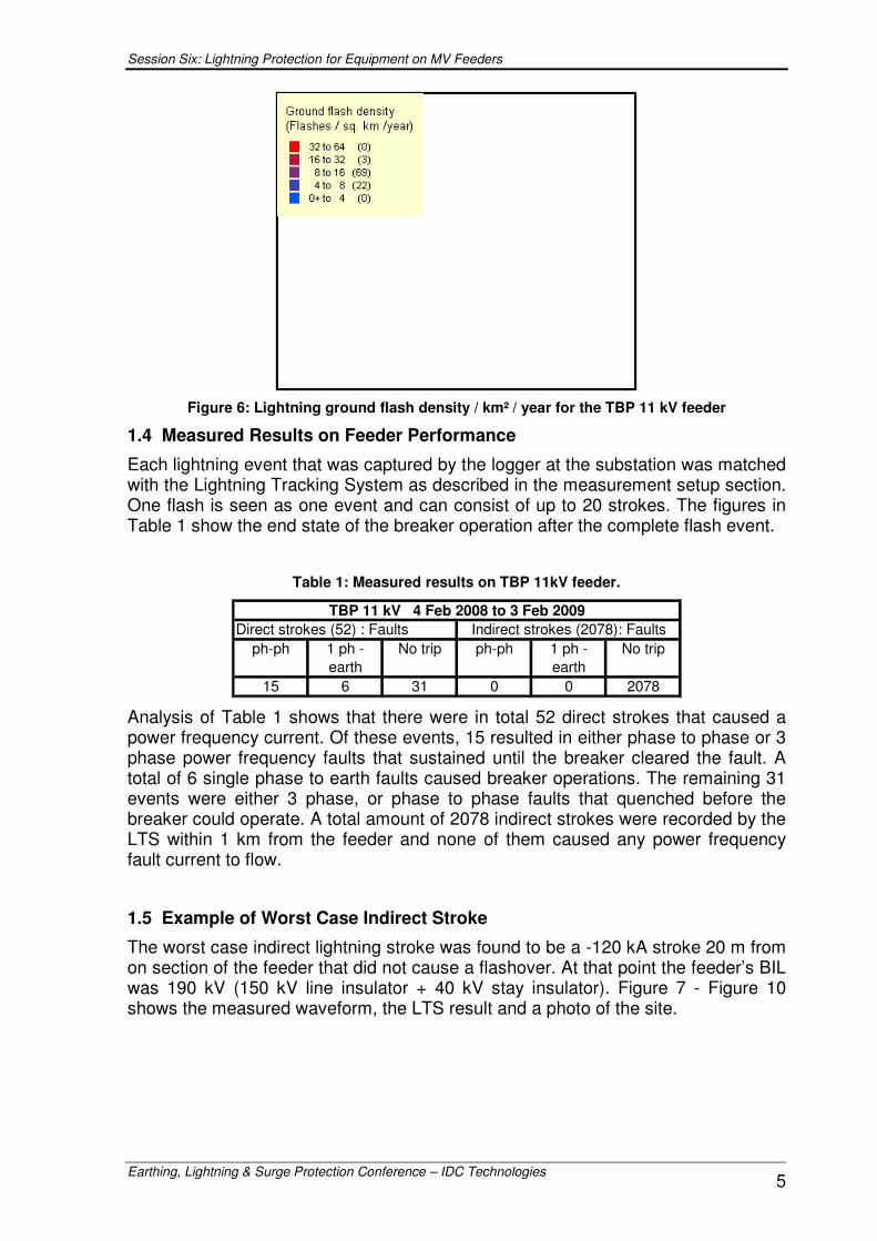
A finding on the feeder is that no trips or fault current could be attributed to an indirect lightning stroke or flash. The lightning ground flash density along the feeders is shown in Figure 6. Most of the faults due to direct flashes quenched before breaker operation. The time taken for the fault current to quench, varied between 10 ms and 2.7 s. The fault current that got quenched also varied from as little as 110 A to in access of 1000 A. Most of the quenched fault currents were between phases.
Session Six: Lightning Protection for Equipment on MV Feeders
Earthing, Lightning & Surge Protection Conference – IDC Technologies 5
Figure 6: Lightning ground flash density / km² / year for the TBP 11 kV feeder
1.4 Measured Results on Feeder Performance
Each lightning event that was captured by the logger at the substation was matched with the Lightning Tracking System as described in the measurement setup section. One flash is seen as one event and can consist of up to 20 strokes. The figures in Table 1 show the end state of the breaker operation after the complete flash event.
Table 1: Measured results on TBP 11kV feeder.
ph-ph 1 ph - earth
No trip ph-ph 1 ph - earth
No trip
15 6 31 0 0 2078
TBP 11 kV 4 Feb 2008 to 3 Feb 2009Direct strokes (52) : Faults Indirect strokes (2078): Faults
Analysis of Table 1 shows that there were in total 52 direct strokes that caused a power frequency current. Of these events, 15 resulted in either phase to phase or 3 phase power frequency faults that sustained until the breaker cleared the fault. A total of 6 single phase to earth faults caused breaker operations. The remaining 31 events were either 3 phase, or phase to phase faults that quenched before the breaker could operate. A total amount of 2078 indirect strokes were recorded by the LTS within 1 km from the feeder and none of them caused any power frequency fault current to flow.
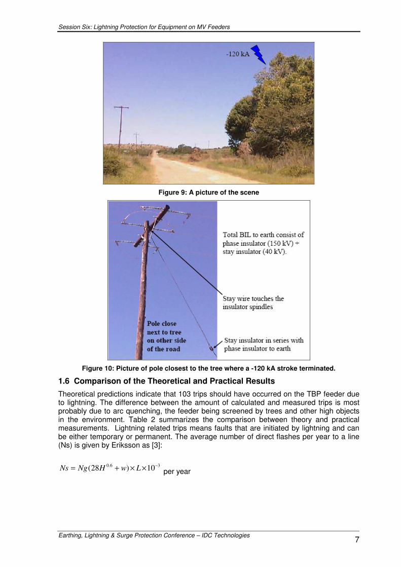
1.5 Example of Worst Case Indirect Stroke
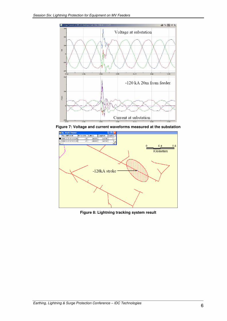
The worst case indirect lightning stroke was found to be a -120 kA stroke 20 m from on section of the feeder that did not cause a flashover. At that point the feeder’s BIL was 190 kV (150 kV line insulator + 40 kV stay insulator). Figure 7 - Figure 10 shows the measured waveform, the LTS result and a photo of the site.
������������ ������
Session Six: Lightning Protection for Equipment on MV Feeders
Earthing, Lightning & Surge Protection Conference – IDC Technologies 6
Figure 7: Voltage and current waveforms measured at the substation
Figure 8: Lightning tracking system result
Session Six: Lightning Protection for Equipment on MV Feeders
Earthing, Lightning & Surge Protection Conference – IDC Technologies 7
Figure 9: A picture of the scene
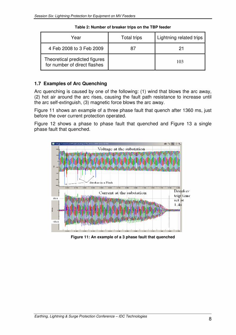
Figure 10: Picture of pole closest to the tree where a -120 kA stroke terminated.
1.6 Comparison of the Theoretical and Practical Results
Theoretical predictions indicate that 103 trips should have occurred on the TBP feeder due to lightning. The difference between the amount of calculated and measured trips is most probably due to arc quenching, the feeder being screened by trees and other high objects in the environment. Table 2 summarizes the comparison between theory and practical measurements. Lightning related trips means faults that are initiated by lightning and can be either temporary or permanent. The average number of direct flashes per year to a line (Ns) is given by Eriksson as [3]:
36.0 10)28( −××+= LwHNgNs per year
Session Six: Lightning Protection for Equipment on MV Feeders
Earthing, Lightning & Surge Protection Conference – IDC Technologies 8
Table 2: Number of breaker trips on the TBP feeder
Year Total trips Lightning related trips
4 Feb 2008 to 3 Feb 2009 87 21
Theoretical predicted figures for number of direct flashes
103
1.7 Examples of Arc Quenching
Arc quenching is caused by one of the following: (1) wind that blows the arc away, (2) hot air around the arc rises, causing the fault path resistance to increase until the arc self-extinguish, (3) magnetic force blows the arc away.
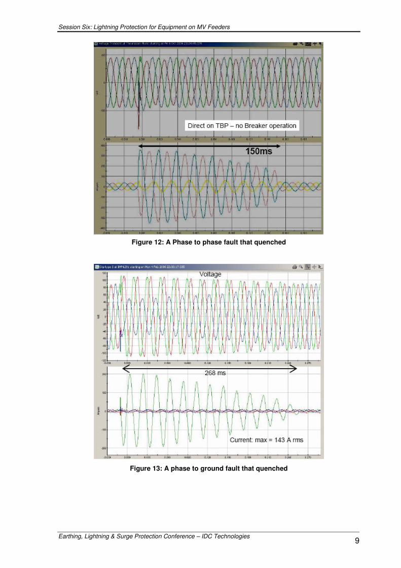
Figure 11 shows an example of a three phase fault that quench after 1360 ms, just before the over current protection operated.
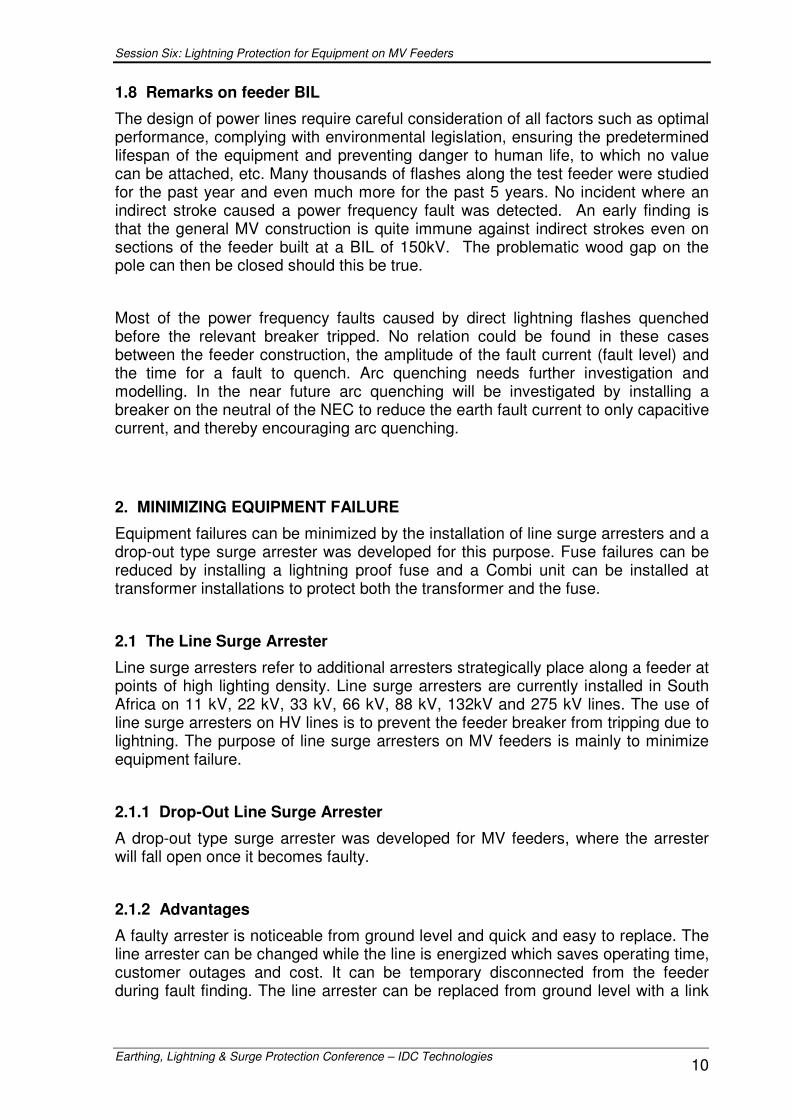
Figure 12 shows a phase to phase fault that quenched and Figure 13 a single phase fault that quenched.
Figure 11: An example of a 3 phase fault that quenched
Session Six: Lightning Protection for Equipment on MV Feeders
Earthing, Lightning & Surge Protection Conference – IDC Technologies 9
Figure 12: A Phase to phase fault that quenched
Figure 13: A phase to ground fault that quenched
Session Six: Lightning Protection for Equipment on MV Feeders
Earthing, Lightning & Surge Protection Conference – IDC Technologies 10
1.8 Remarks on feeder BIL
The design of power lines require careful consideration of all factors such as optimal performance, complying with environmental legislation, ensuring the predetermined lifespan of the equipment and preventing danger to human life, to which no value can be attached, etc. Many thousands of flashes along the test feeder were studied for the past year and even much more for the past 5 years. No incident where an indirect stroke caused a power frequency fault was detected. An early finding is that the general MV construction is quite immune against indirect strokes even on sections of the feeder built at a BIL of 150kV. The problematic wood gap on the pole can then be closed should this be true.
Most of the power frequency faults caused by direct lightning flashes quenched before the relevant breaker tripped. No relation could be found in these cases between the feeder construction, the amplitude of the fault current (fault level) and the time for a fault to quench. Arc quenching needs further investigation and modelling. In the near future arc quenching will be investigated by installing a breaker on the neutral of the NEC to reduce the earth fault current to only capacitive current, and thereby encouraging arc quenching.
2. MINIMIZING EQUIPMENT FAILURE
Equipment failures can be minimized by the installation of line surge arresters and a drop-out type surge arrester was developed for this purpose. Fuse failures can be reduced by installing a lightning proof fuse and a Combi unit can be installed at transformer installations to protect both the transformer and the fuse.
2.1 The Line Surge Arrester
Line surge arresters refer to additional arresters strategically place along a feeder at points of high lighting density. Line surge arresters are currently installed in South Africa on 11 kV, 22 kV, 33 kV, 66 kV, 88 kV, 132kV and 275 kV lines. The use of line surge arresters on HV lines is to prevent the feeder breaker from tripping due to lightning. The purpose of line surge arresters on MV feeders is mainly to minimize equipment failure.
2.1.1 Drop-Out Line Surge Arrester
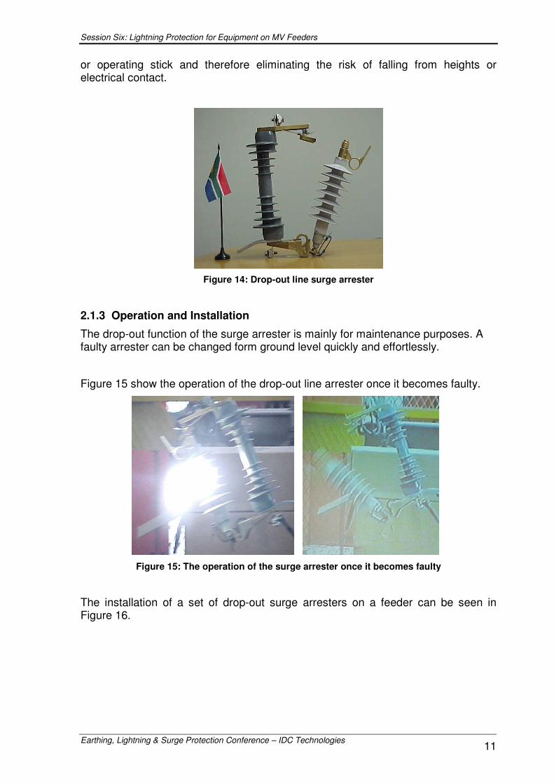
A drop-out type surge arrester was developed for MV feeders, where the arrester will fall open once it becomes faulty.
2.1.2 Advantages
A faulty arrester is noticeable from ground level and quick and easy to replace. The line arrester can be changed while the line is energized which saves operating time, customer outages and cost. It can be temporary disconnected from the feeder during fault finding. The line arrester can be replaced from ground level with a link
Session Six: Lightning Protection for Equipment on MV Feeders
Earthing, Lightning & Surge Protection Conference – IDC Technologies 11
or operating stick and therefore eliminating the risk of falling from heights or electrical contact.
Figure 14: Drop-out line surge arrester
2.1.3 Operation and Installation
The drop-out function of the surge arrester is mainly for maintenance purposes. A faulty arrester can be changed form ground level quickly and effortlessly.
Figure 15 show the operation of the drop-out line arrester once it becomes faulty.
Figure 15: The operation of the surge arrester once it becomes faulty
The installation of a set of drop-out surge arresters on a feeder can be seen in Figure 16.
Session Six: Lightning Protection for Equipment on MV Feeders
Earthing, Lightning & Surge Protection Conference – IDC Technologies 12
Figure 16: The installation of drop-out line surge arresters
2.2 The Lightning Proof Fuse
Annually many thousands (12 789) of rural fuses in the North Western Region are lost particularly during bad weather (lightning) conditions.
If the overtime costs to replace the fuse, material costs and wear and tear on vehicles are taken into account, it is not difficult to see that this inconvenience has large financial implications as well as customer dissatisfaction.
An alternative fuse technology is presented to avoid nuisance fuse failures on rural feeders due to lightning impulses while also making proper 50Hz protection grading possible.
2.2.1 Fuse Operations at Lightning Frequencies
It is relatively easy to grade fuses for correct 50 Hz current operation, but fuses are also sensitive for high currents such as these found in lightning.
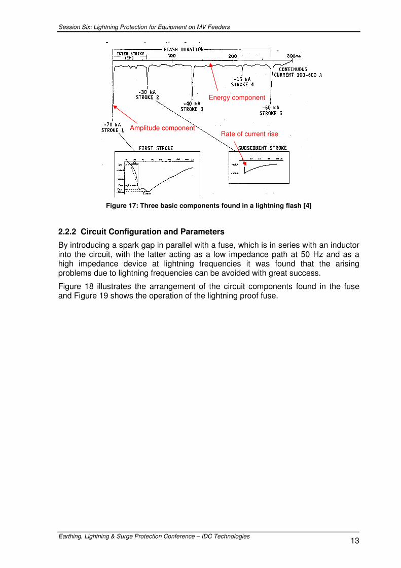
Normally lightning consists of a first stroke followed by several subsequent strokes as it can be seen in the illustration shown in Figure 17. The illustration shows that lightning consists of three major components namely an amplitude component, the rate at which the current rises and an energy component that exists due to the DC current found within a lightning flash. The total surface area underneath the wave form represents the energy that needs to be dissipated by the fuse and surge arresters on the line.
The combination of all of the above given factors contributes to the reason why rural feeder over current protection fuses blow for lightning impulses. In practice this means that since lightning flashes are of very short duration and consists of high peak values with a DC component, the maximum RMS current handling capability of the fuse is reached almost instantaneously, resulting in a blown fuse (this is mainly due to the energy dissipation in the fuse).
However, this problem can be avoided by introducing a few passive components into the circuit.
Session Six: Lightning Protection for Equipment on MV Feeders
Earthing, Lightning & Surge Protection Conference – IDC Technologies 13
Figure 17: Three basic components found in a lightning flash [4]
2.2.2 Circuit Configuration and Parameters
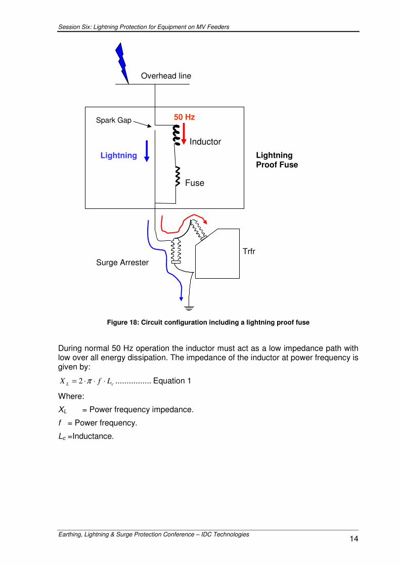
By introducing a spark gap in parallel with a fuse, which is in series with an inductor into the circuit, with the latter acting as a low impedance path at 50 Hz and as a high impedance device at lightning frequencies it was found that the arising problems due to lightning frequencies can be avoided with great success.
Figure 18 illustrates the arrangement of the circuit components found in the fuse and Figure 19 shows the operation of the lightning proof fuse.
Energy component
Rate of current rise Amplitude component
Session Six: Lightning Protection for Equipment on MV Feeders
Earthing, Lightning & Surge Protection Conference – IDC Technologies 14
Figure 18: Circuit configuration including a lightning proof fuse
During normal 50 Hz operation the inductor must act as a low impedance path with low over all energy dissipation. The impedance of the inductor at power frequency is given by:
cL LfX ⋅⋅⋅= π2 ................ Equation 1
Where:
XL = Power frequency impedance.
f = Power frequency.
Lc =Inductance.
Fuse
Inductor
50 Hz
Lightning
Overhead line
Spark Gap
Surge Arrester Trfr
Lightning Proof Fuse
Session Six: Lightning Protection for Equipment on MV Feeders
Earthing, Lightning & Surge Protection Conference – IDC Technologies 15
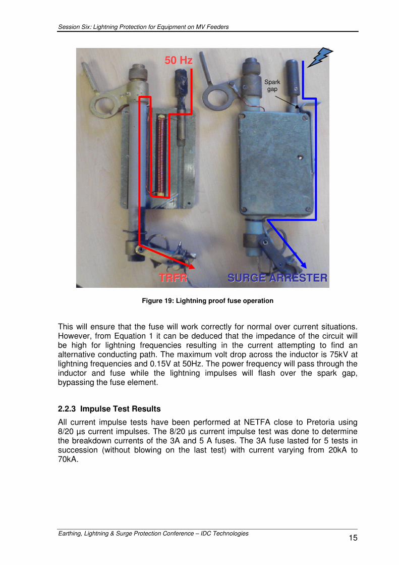
Figure 19: Lightning proof fuse operation
This will ensure that the fuse will work correctly for normal over current situations. However, from Equation 1 it can be deduced that the impedance of the circuit will be high for lightning frequencies resulting in the current attempting to find an alternative conducting path. The maximum volt drop across the inductor is 75kV at lightning frequencies and 0.15V at 50Hz. The power frequency will pass through the inductor and fuse while the lightning impulses will flash over the spark gap, bypassing the fuse element.
2.2.3 Impulse Test Results
All current impulse tests have been performed at NETFA close to Pretoria using 8/20 µs current impulses. The 8/20 µs current impulse test was done to determine the breakdown currents of the 3A and 5 A fuses. The 3A fuse lasted for 5 tests in succession (without blowing on the last test) with current varying from 20kA to 70kA.
TTRRFFRR
5500 HHzz
Spark gap
SSUURRGGEE AARRRREESSTTEERR
Session Six: Lightning Protection for Equipment on MV Feeders
Earthing, Lightning & Surge Protection Conference – IDC Technologies 16
2.2.4 Advantages and Disadvantages
The advantage of the lighting proof fuse is that it eliminates nuisance fusing on MV feeders caused by lightning and still allows sufficient protection grading. The fuse fits in a standard fuse bracket.
The disadvantage of the fuse is that it does not protect the pole mounted transformer from lightning. Secondly, whenever the fuse blows for a 50Hz fault at the transformer, a standing back flash-over across the spark gap while the fuse is falling open will occur, which will be cleared by the upstream breaker. The breaker will auto reclose in about 3s and the faulty transformer is isolated from the network.
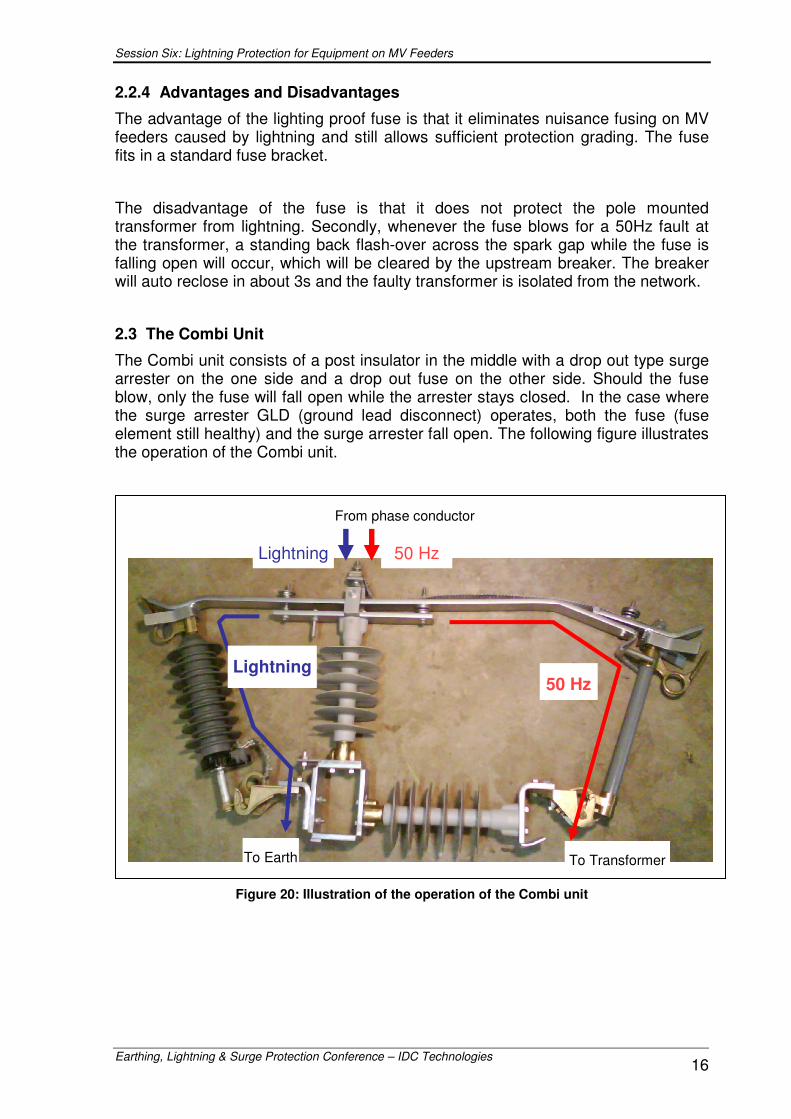
2.3 The Combi Unit
The Combi unit consists of a post insulator in the middle with a drop out type surge arrester on the one side and a drop out fuse on the other side. Should the fuse blow, only the fuse will fall open while the arrester stays closed. In the case where the surge arrester GLD (ground lead disconnect) operates, both the fuse (fuse element still healthy) and the surge arrester fall open. The following figure illustrates the operation of the Combi unit.
Figure 20: Illustration of the operation of the Combi unit
50 Hz Lightning
From phase conductor
To Transformer To Earth
Lightning 50 Hz
Session Six: Lightning Protection for Equipment on MV Feeders
Earthing, Lightning & Surge Protection Conference – IDC Technologies 17
2.3.1 Development of the Combi unit
The Combi Unit was initially developed to minimize the MV fuse and transformer failures during lightning activities.
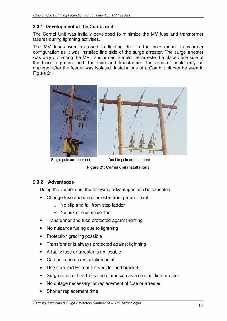
The MV fuses were exposed to lighting due to the pole mount transformer configuration as it was installed line side of the surge arrester. The surge arrester was only protecting the MV transformer. Should the arrester be placed line side of the fuse to protect both the fuse and transformer, the arrester could only be changed after the feeder was isolated. Installations of a Combi unit can be seen in Figure 21.
Single pole arrangement Double pole arrangementSingle pole arrangement Double pole arrangement Figure 21: Combi unit installations
2.3.2 Advantages
Using the Combi unit, the following advantages can be expected:
• Change fuse and surge arrester from ground level:
o No slip and fall from step ladder
o No risk of electric contact
• Transformer and fuse protected against lighting
• No nuisance fusing due to lightning
• Protection grading possible
• Transformer is always protected against lightning
• A faulty fuse or arrester is noticeable
• Can be used as an isolation point
• Use standard Eskom fuse/holder and bracket
• Surge arrester has the same dimension as a dropout line arrester
• No outage necessary for replacement of fuse or arrester
• Shorter replacement time
Session Six: Lightning Protection for Equipment on MV Feeders
Earthing, Lightning & Surge Protection Conference – IDC Technologies 18
2.3.3 Performance of the Combi unit
A total of 1064 pole mount installation were fitted with Combi units over the past 5 years. At all these installations at least one transformer failure occurred annually. After the installation of Combi units only 11 transformers failed over the last 3 years instead of an expected 1500 transformer failures.
Reasons of the failures:
• Two installations had neither neutral arresters nor any connection between the 400V neutral and earth. This seems to be the reason for failure of the transformers.
• One installation was hit by a lightning flash consisting of 18 strokes. The arresters failed but in the process the transformer was damaged.
• One transformer failed shortly after installation with no lightning around – maybe the transformer was already damaged.
• Seven installations still need to be visited.
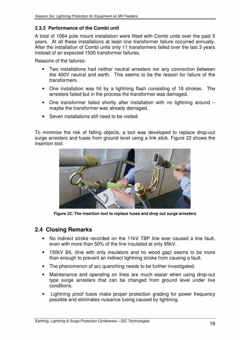
To minimize the risk of falling objects, a tool was developed to replace drop-out surge arresters and fuses from ground level using a link stick. Figure 22 shows the insertion tool.
Figure 22: The insertion tool to replace fuses and drop out surge arresters
2.4 Closing Remarks • No indirect stroke recorded on the 11kV TBP line ever caused a line fault,
even with more than 50% of the line insulated at only 95kV.
• 150kV BIL (line with only insulators and no wood gap) seems to be more than enough to prevent an indirect lightning stroke from causing a fault.
• The phenomenon of arc quenching needs to be further investigated.
• Maintenance and operating on lines are much easier when using drop-out type surge arresters that can be changed from ground level under live conditions.
• Lightning proof fuses make proper protection grading for power frequency possible and eliminates nuisance fusing caused by lightning.
Session Six: Lightning Protection for Equipment on MV Feeders
Earthing, Lightning & Surge Protection Conference – IDC Technologies 19
• The Combi unit reduces equipment failure (fuses and transformers) significantly.
References [1] AC Britten, R.E. Kohimeyer, M.E. Mathebula, “Laboratory study of long, low current power frequency arcs: initial results.” IEEE Africon, October 2002.
[2] AC Britten, “Practical insulation co-ordination of woodpole Distribution lines in high-lightning areas.” IEEE Africon, Swaziland, 1994.
[3] A.J. Eriksson, The incidence of lightning strikes to power lines, IEEE/PES Winter Meeting, New York, February 1986.
[4] C T Gaunt, A C Britten and H J Geldenhuys, “Insulation co-ordination of unshielded distribution lines from 1 kV to 36 kV”, SAIEE, pp. 4.