Embed Size (px)
Citation preview
INTORQ BFK458
j
setting the standard
Operating Instructions
www.intorq.com
Electromagnetically released spring-applied brake
j | BA 14.0168 | 05/2012
2
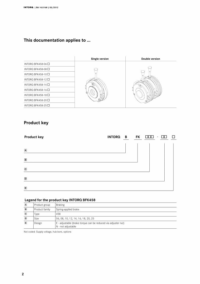
This documentation applies to ...
Single version Double version
INTORQ BFK458-06 INTORQ BFK458-08 INTORQ BFK458-10 INTORQ BFK458-12 INTORQ BFK458-14 INTORQ BFK458-16 INTORQ BFK458-18 INTORQ BFK458-20 INTORQ BFK458-25
Product key
Product key INTORQ B FK -
Legend for the product key INTORQ BFK458 Product group Braking
Product family Spring-applied brake
Type 458
Size 06, 08, 10, 12, 14, 16, 18, 20, 25
Design E - adjustable (brake torque can be reduced via adjuster nut)N - not adjustable
Not coded: Supply voltage, hub bore, options
j | BA 14.0168 | 05/2012
i
3
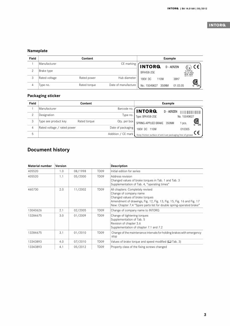
Nameplate
Field Content Example
1 Manufacturer CE marking
BFK458-25E
180V DC 110W 38H7
No.: 15049627 350NM 01.03.05
D - AERZENj2 Brake type
3 Rated voltage Rated power Hub diameter
4 Type no. Rated torque Date of manufacture
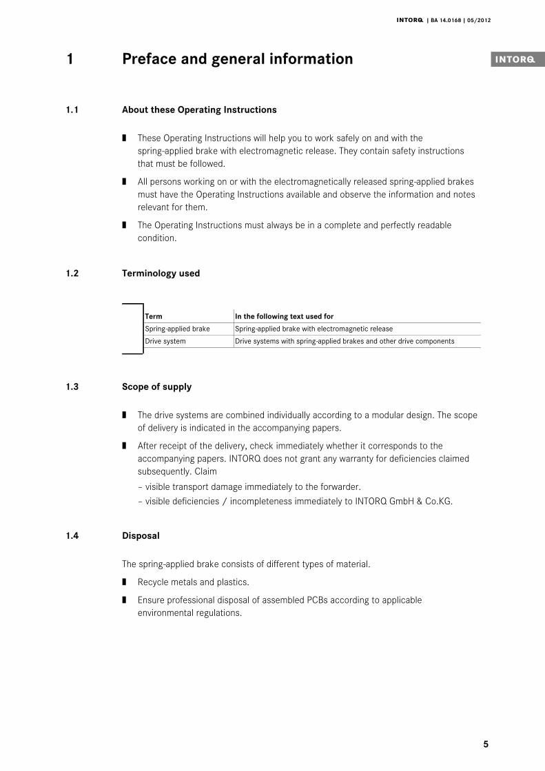
Packaging sticker
Field Content Example
1 Manufacturer Barcode no.D - AERZEN
Type: BFK458-25E No. 15049627
180V DC 110W 010305
Keep friction surface of anti-rust packaging free of grease
SPRING-APPLIED BRAKE 350NM 1 pcs.
j
2 Designation Type no.
3 Type see product key Rated torque Qty. per box
4 Rated voltage / rated power Date of packaging
5 Addition / CE mark
Document history
Material number Version Description
405520 1.0 08/1998 TD09 Initial edition for series
405520 1.1 05/2000 TD09 Address revisionChanged values of brake torques in Tab. 1 and Tab. 3Supplementation of Tab. 4, ”operating times”
460730 2.0 11/2002 TD09 All chapters: Completely revisedChange of company nameChanged values of brake torquesAmendment of drawings, Fig. 12, Fig. 13, Fig. 15, Fig. 16 and Fig. 17New: Chapter 7.4 ”Spare parts list for double spring-operated brake”
13040626 2.1 02/2005 TD09 Change of company name to INTORQ
13284675 3.0 01/2009 TD09 Change of tightening torquesSupplementation of Tab. 5Revision of chapter 3.6Supplementation of chapter 7.1 and 7.2
13284675 3.1 01/2010 TD09 Change of the maintenance intervals for holding brakes with emergencystop
13343893 4.0 07/2010 TD09 Values of brake torque and speed modified ( Tab. 3)
13343893 4.1 05/2012 TD09 Property class of the fixing screws changed0Abb. 0Tab. 0

Contentsi
j | BA 14.0168 | 05/2012
4
1 Preface and general information 5. . . . . . . . . . . . . . . . . . . . . . . . . . . . . . . . . . . . . . .
1.1 About these Operating Instructions 5. . . . . . . . . . . . . . . . . . . . . . . . . . . . . . . . . . .
1.2 Terminology used 5. . . . . . . . . . . . . . . . . . . . . . . . . . . . . . . . . . . . . . . . . . . . . . . . .
1.3 Scope of supply 5. . . . . . . . . . . . . . . . . . . . . . . . . . . . . . . . . . . . . . . . . . . . . . . . . .
1.4 Disposal 5. . . . . . . . . . . . . . . . . . . . . . . . . . . . . . . . . . . . . . . . . . . . . . . . . . . . . . . .
1.5 Drive systems 6. . . . . . . . . . . . . . . . . . . . . . . . . . . . . . . . . . . . . . . . . . . . . . . . . . . .
1.6 Legal regulations 6. . . . . . . . . . . . . . . . . . . . . . . . . . . . . . . . . . . . . . . . . . . . . . . . .
2 Safety instructions 7. . . . . . . . . . . . . . . . . . . . . . . . . . . . . . . . . . . . . . . . . . . . . . . . . . .
2.1 General safety information 7. . . . . . . . . . . . . . . . . . . . . . . . . . . . . . . . . . . . . . . . . .
2.2 Personnel responsible for safety 8. . . . . . . . . . . . . . . . . . . . . . . . . . . . . . . . . . . . . .
2.3 Notes used 9. . . . . . . . . . . . . . . . . . . . . . . . . . . . . . . . . . . . . . . . . . . . . . . . . . . . . .
3 Technical data 10. . . . . . . . . . . . . . . . . . . . . . . . . . . . . . . . . . . . . . . . . . . . . . . . . . . . . . .3.1 Product description 10. . . . . . . . . . . . . . . . . . . . . . . . . . . . . . . . . . . . . . . . . . . . . . .
3.2 Brake torques 12. . . . . . . . . . . . . . . . . . . . . . . . . . . . . . . . . . . . . . . . . . . . . . . . . . .
3.3 Rated data 14. . . . . . . . . . . . . . . . . . . . . . . . . . . . . . . . . . . . . . . . . . . . . . . . . . . . . .
3.4 Operating times 17. . . . . . . . . . . . . . . . . . . . . . . . . . . . . . . . . . . . . . . . . . . . . . . . . .
3.5 Operating frequency / friction work 19. . . . . . . . . . . . . . . . . . . . . . . . . . . . . . . . . .
3.6 Emission 20. . . . . . . . . . . . . . . . . . . . . . . . . . . . . . . . . . . . . . . . . . . . . . . . . . . . . . .
4 Mechanical installation 21. . . . . . . . . . . . . . . . . . . . . . . . . . . . . . . . . . . . . . . . . . . . . . . .
4.1 Necessary tools 21. . . . . . . . . . . . . . . . . . . . . . . . . . . . . . . . . . . . . . . . . . . . . . . . . .
4.2 Mounting 22. . . . . . . . . . . . . . . . . . . . . . . . . . . . . . . . . . . . . . . . . . . . . . . . . . . . . . .
4.3 Installation 22. . . . . . . . . . . . . . . . . . . . . . . . . . . . . . . . . . . . . . . . . . . . . . . . . . . . . .
5 Electrical installation 30. . . . . . . . . . . . . . . . . . . . . . . . . . . . . . . . . . . . . . . . . . . . . . . . .
5.1 Bridge/half-wave rectifiers 30. . . . . . . . . . . . . . . . . . . . . . . . . . . . . . . . . . . . . . . . .
5.2 Electrical connection 32. . . . . . . . . . . . . . . . . . . . . . . . . . . . . . . . . . . . . . . . . . . . . .
6 Commissioning and operation 36. . . . . . . . . . . . . . . . . . . . . . . . . . . . . . . . . . . . . . . . . .
6.1 Functional test 36. . . . . . . . . . . . . . . . . . . . . . . . . . . . . . . . . . . . . . . . . . . . . . . . . . .
6.2 Reducing the brake torque 40. . . . . . . . . . . . . . . . . . . . . . . . . . . . . . . . . . . . . . . . .
6.3 During operation 40. . . . . . . . . . . . . . . . . . . . . . . . . . . . . . . . . . . . . . . . . . . . . . . . .
7 Maintenance/repair 41. . . . . . . . . . . . . . . . . . . . . . . . . . . . . . . . . . . . . . . . . . . . . . . . . .
7.1 Wear of spring-applied brakes 41. . . . . . . . . . . . . . . . . . . . . . . . . . . . . . . . . . . . . . .
7.2 Inspections 42. . . . . . . . . . . . . . . . . . . . . . . . . . . . . . . . . . . . . . . . . . . . . . . . . . . . . .
7.3 Maintenance 43. . . . . . . . . . . . . . . . . . . . . . . . . . . . . . . . . . . . . . . . . . . . . . . . . . . .
7.4 Spare-parts list 46. . . . . . . . . . . . . . . . . . . . . . . . . . . . . . . . . . . . . . . . . . . . . . . . . .
7.5 Spare parts order 48. . . . . . . . . . . . . . . . . . . . . . . . . . . . . . . . . . . . . . . . . . . . . . . .
8 Troubleshooting and fault elimination 50. . . . . . . . . . . . . . . . . . . . . . . . . . . . . . . . . . .
Preface and general information1 i
j | BA 14.0168 | 05/2012
5
1 Preface and general information
1.1 About these Operating Instructions
| These Operating Instructions will help you to work safely on and with thespring-applied brake with electromagnetic release. They contain safety instructionsthat must be followed.
| All persons working on or with the electromagnetically released spring-applied brakesmust have the Operating Instructions available and observe the information and notesrelevant for them.
| The Operating Instructions must always be in a complete and perfectly readablecondition.
1.2 Terminology used
Term In the following text used for
Spring-applied brake Spring-applied brake with electromagnetic release
Drive system Drive systems with spring-applied brakes and other drive components
1.3 Scope of supply
| The drive systems are combined individually according to a modular design. The scopeof delivery is indicated in the accompanying papers.
| After receipt of the delivery, check immediately whether it corresponds to theaccompanying papers. INTORQ does not grant any warranty for deficiencies claimedsubsequently. Claim
– visible transport damage immediately to the forwarder.
– visible deficiencies / incompleteness immediately to INTORQ GmbH & Co.KG.
1.4 Disposal
The spring-applied brake consists of different types of material.
| Recycle metals and plastics.
| Ensure professional disposal of assembled PCBs according to applicableenvironmental regulations.
Preface and general information1
j | BA 14.0168 | 05/2012
6
1.5 Drive systems
1.5.1 Labelling
Drive systems and components are unambiguously designated by the indications on thenameplate.
Manufacturer: INTORQ GmbH & Co KG, Wülmser Weg 5, D-31855 Aerzen
| The spring-applied INTORQ brake is also delivered in single modules and individuallycombined to its modular design. The data - package labels, nameplate, and type codein particular - apply to the complete stator.
| If single modules are delivered, the labelling is missing.
1.6 Legal regulations
Liability
| The information, data and notes in these Operating Instructions met the state of theart at the time of printing. Claims referring to drive systems which have already beensupplied cannot be derived from the information, illustrations and descriptions.
| We do not accept any liability for damage and operating interference caused by:
– inappropriate use
– unauthorised modifications to the drive system
– improper working on and with the drive system
– operating faults
– disregarding these Operating Instructions
Warranty
| Terms of warranty: see terms of sale and delivery of INTORQ GmbH & Co. KG.
| Warranty claims must be made to INTORQ immediately after detecting defects orfaults.
| The warranty is void in all cases where liability claims cannot be made.
Safety instructions2 i
j | BA 14.0168 | 05/2012
7
2 Safety instructions
2.1 General safety information
| These safety notes do not claim to be complete. If any questions or problems occur,please contact INTORQ GmbH & Co. KG.
| The spring-applied brake corresponds to the state of the art at the time of delivery andis generally safe to operate.
| The spring-applied brake presents a danger for persons, the spring-applied brake itselfand other material assets of the operator if
– non-qualified personnel work on and with the spring-applied brake.
– the spring-applied brake is used improperly.
| The spring-applied brakes must be planned in such a way that if they are correctlyinstalled and used for their designed purpose in fault-free operation, they fulfil theirfunction and do not put any persons at risk. This also applies to the interaction thereofwith the overall system.
| Take appropriate measures to ensure that the failure of the spring-applied brake willnot lead to damage to material.
| Do not operate the spring-applied brake unless it is in perfect condition.
| Retrofittings, changes or alterations of the spring-applied brake are generallyforbidden. In any case, they are subject to the consultation withINTORQ GmbH & Co. KG.
| The friction lining and the friction surfaces must be carefully protected from oil orgrease since even small amounts of lubricants reduce the brake torque considerably.
| The brake torque will usually not be influenced if the brake is used under theenvironmental conditions that apply to IP54. Because of the numerous possibilities ofusing the brake, it is however necessary to check the functionality of all mechanicalcomponents under the corresponding operating conditions.
Safety instructions2
j | BA 14.0168 | 05/2012
8
2.2 Personnel responsible for safety
Operator
| An operator is any natural or legal person who uses the spring-applied brake or onwhose behalf the spring-applied brake is used.
| The operator or his safety personnel must ensure
– that all relevant regulations, notes and laws will be complied with,
– that only qualified personnel will work on and with the drive system,
– that the Operating Instructions will be available to the personnel working on and withthe brake at all times,
– that unqualified personnel will not be allowed to work on and with the spring-appliedbrake.
Skilled personnel
Skilled personnel are persons who - because of their education, experience, instructions, andknowledge about corresponding standards and regulations, rules for the prevention ofaccidents, and operating conditions - are authorised by the person responsible for the safetyof the plant to perform the required actions and who are able to recognise potential hazards.(See IEC 364, definition of skilled personnel)
Application as directed
| Drive systems
– are intended for use in machinery and systems.
– are suitable for use in potentially explosive atmospheres of zone II for steadyoperation (holding or parking brake), explosion group II and temperature class T4.
– must only be used for the purposes ordered and confirmed.
– must only be operated under the ambient conditions prescribed in these OperatingInstructions.
– must not be operated beyond their corresponding power limits.
Any other use shall be deemed inappropriate!
Possible applications of the INTORQ spring-applied brake
| No explosive or aggressive atmosphere.
| Humidity, no restrictions.
| Ambient temperature -20°C to +40°C.
| With high humidity and low temperatures
– Take measures to protect armature plate and rotor from freezing.
| Protect electrical connections against contact.
Safety instructions2 i
j | BA 14.0168 | 05/2012
9
2.3 Notes used
The following pictographs and signal words are used in this documentation to indicate dangersand important information:
Safety instructions
Structure of safety instructions:
Danger!Characterises the type and severity of dangerNoteDescribes the dangerPossible consequences:| List of possible consequences if the safety instructions are disregarded.Protective measure:| List of protective measures to avoid the danger.
Pictograph and signal word Meaning
Danger!Danger of personal injury through dangerous electrical voltageReference to an imminent danger that may result in death or seriouspersonal injury if the corresponding measures are not taken.
Danger!Danger of personal injury through a general source of dangerReference to an imminent danger that may result in death or seriouspersonal injury if the corresponding measures are not taken.
Stop!Danger of property damageReference to a possible danger that may result in property damage if thecorresponding measures are not taken.
Application notes
Pictograph and signal word Meaning
Note! Important note to ensure troublefree operation
Tip! Useful tip for simple handling
Reference to another documentation
Technical data3
j | BA 14.0168 | 05/2012
10
3 Technical data
3.1 Product description
1 2
3
4
5
6
8
9
7
KL 14.0606/1
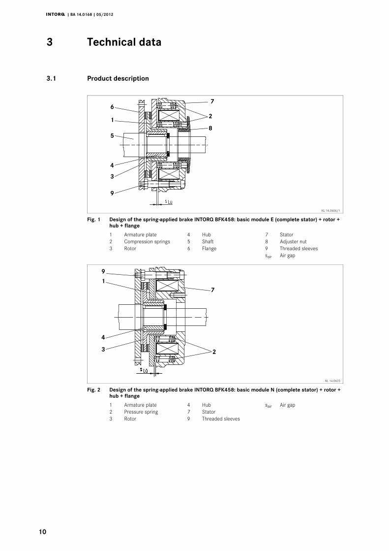
Fig. 1 Design of the spring-applied brake INTORQ BFK458: basic module E (complete stator) + rotor +hub + flange
1 Armature plate 4 Hub 7 Stator2 Compression springs 5 Shaft 8 Adjuster nut3 Rotor 6 Flange 9 Threaded sleeves
sair Air gap
1
23
4
9
7
KL 14.0623
Fig. 2 Design of the spring-applied brake INTORQ BFK458: basic module N (complete stator) + rotor +hub + flange
1 Armature plate 4 Hub sair Air gap2 Pressure spring 7 Stator3 Rotor 9 Threaded sleeves
Technical data3 i
j | BA 14.0168 | 05/2012
11
3.1.1 General information
The spring-applied brake INTORQ BFK458- is a single-disk brake with two frictionsurfaces. Several compression springs (2) create the braking torque by friction locking. Thebrake is released electromagnetically.
The spring-applied brake is designed for the conversion of mechanical work and kinetic energyinto heat. For operating speed, see chapter 3.3 Rated data. Due to the static brake torque,the brake can hold loads without speed difference. Emergency braking is possible at highspeed, see chapter 3.3 Rated data. The more friction work, the higher the wear.
3.1.2 Braking
During braking, the rotor (3), which is axially movable on the hub (4), is pressed againstthe friction surface - via the armature plate (1) - by means of the inner and outer springs(2). The asbestos-free friction linings ensure a high brake torque with low wear. The braketorque is transmitted between hub (4) and rotor (3) via the splines.
3.1.3 Brake release
In braked state, there is an air gap ”sair” between stator (7) and armature plate (1). To releasethe brake, the stator coil (7) is excited with the DC voltage provided. The magnetic forcegenerated attracts the armature plate (1) towards the stator (7) against the spring force. Therotor (3) is then released and can rotate freely.
3.1.4 Reducing the brake torque
For basic module E (adjustable), the spring force and thus the brake torque can be reducedby unscrewing the adjuster nut (8) ( 40).
3.1.5 Manual release (optional)
The manual release is optionally available for short-term releases when no voltage is applied.The manual release can be retrofitted.
3.1.6 Microswitch (optional)
The manufacturer offers the microswitch for air-gap or wear monitoring. The user must providethe corresponding electrical connection ( 32 following).
When air-gap monitoring, the motor does not start before the brake has been released. Withthis set-up, all possible faults are monitored. For example, in the event of defective rectifiers,interrupted connection cables, defective coils, or excessive air gaps the motor will not start.
When checking the wear, no current will be applied to the brake and the motor if the air gapis too large.
Technical data3
j | BA 14.0168 | 05/2012
12
3.1.7 Encapsulated design (optional)
This design not only avoids the penetration of spray water and dust, but also the spreadingof abrasion particles outside the brake. This is achieved by:
| a cover seal over the armature plate and rotor,
| a cover in the adjuster nut,
| a shaft seal in the adjuster nut for continuous shafts (option).
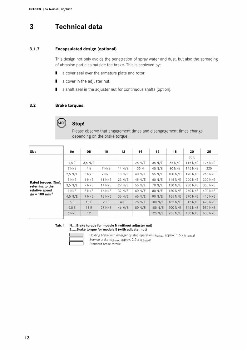
3.2 Brake torques
Stop!Please observe that engagement times and disengagement times changedepending on the brake torque.
Size 06 08 10 12 14 16 18 20 25
80 E
Rated torques [Nm],referring to therelative speedΔn = 100 min-1
1,5 E 3,5 N/E 25 N/E 35 N/E 65 N/E 115 N/E 175 N/E
2 N/E 4 E 7 N/E 14 N/E 35 N 45 N/E 80 N/E 145 N/E 220
2,5 N/E 5 N/E 9 N/E 18 N/E 40 N/E 55 N/E 100 N/E 170 N/E 265 N/E
3 N/E 6 N/E 11 N/E 23 N/E 45 N/E 60 N/E 115 N/E 200 N/E 300 N/E
3,5 N/E 7 N/E 14 N/E 27 N/E 55 N/E 70 N/E 130 N/E 230 N/E 350 N/E
4 N/E 8 N/E 16 N/E 32 N/E 60 N/E 80 N/E 150 N/E 260 N/E 400 N/E
4,5 N/E 9 N/E 18 N/E 36 N/E 65 N/E 90 N/E 165 N/E 290 N/E 445 N/E
5 E 10 E 20 E 40 E 75 N/E 100 N/E 185 N/E 315 N/E 490 N/E
5,5 E 11 E 23 N/E 46 N/E 80 N/E 105 N/E 200 N/E 345 N/E 530 N/E
6 N/E 12 125 N/E 235 N/E 400 N/E 600 N/E
Tab. 1 N.....Brake torque for module N (without adjuster nut)E......Brake torque for module E (with adjuster nut)
Holding brake with emergency stop operation (sLümax. approx. 1.5 x sLürated)Service brake (sLümax. approx. 2.5 x sLürated)Standard brake torque
Technical data3 i
j | BA 14.0168 | 05/2012
13
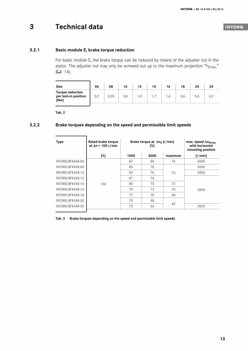
3.2.1 Basic module E, brake torque reduction
For basic module E, the brake torque can be reduced by means of the adjuster nut in thestator. The adjuster nut may only be screwed out up to the maximum projection ”hEmax.”( 14).
Size 06 08 10 12 14 16 18 20 25
Torque reductionper lock-in position[Nm]
0,2 0,35 0,8 1,3 1,7 1,6 3,6 5,6 6,2
Tab. 2
3.2.2 Brake torques depending on the speed and permissible limit speeds
Type Rated brake torqueat Δn = 100 r/min
Brake torque at Δn0 [r/min][%]
max. speed Δn0max.with horizontal
mounting position
[%] 1500 3000 maximum [r/min]
INTORQ BFK458-06
100
87 80 74 6000
INTORQ BFK458-08 85 78
73
5000
INTORQ BFK458-10 83 76 4000
INTORQ BFK458-12 81 74
3600
INTORQ BFK458-14 80 73 72
INTORQ BFK458-16 79 72 70
INTORQ BFK458-18 77 70 68
INTORQ BFK458-20 75 6866
INTORQ BFK458-25 73 66 3000
Tab. 3 Brake torques depending on the speed and permissible limit speeds
Technical data3
j | BA 14.0168 | 05/2012
14
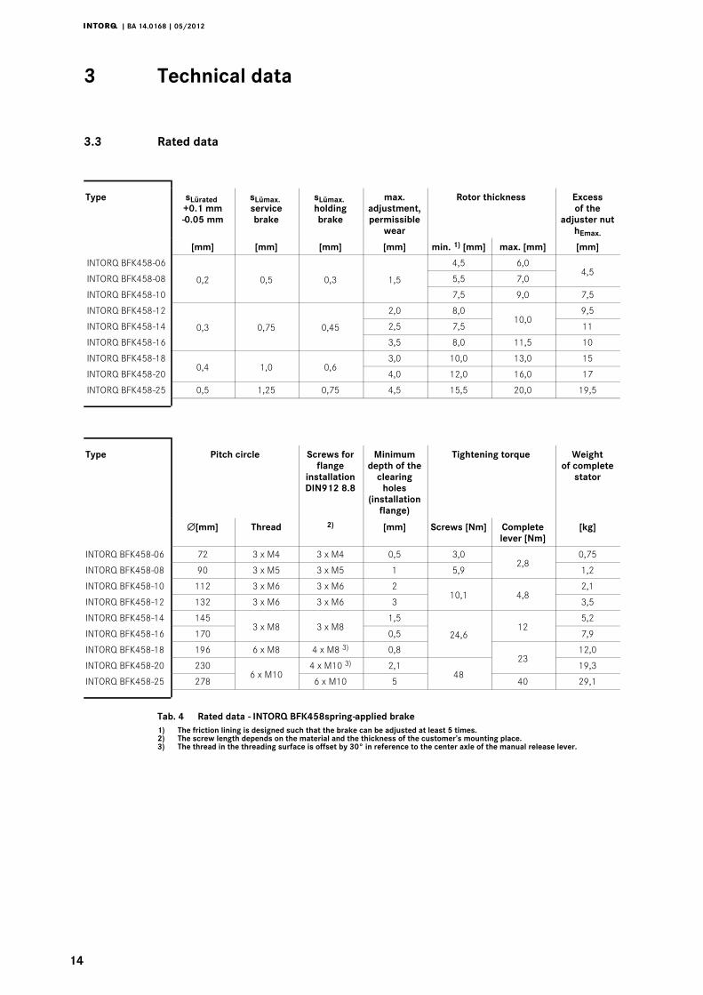
3.3 Rated data
Type sLürated+0.1 mm-0.05 mm
sLümax.servicebrake
sLümax.holdingbrake
max.adjustment,permissible
wear
Rotor thickness Excessof the
adjuster nuthEmax.
[mm] [mm] [mm] [mm] min. 1) [mm] max. [mm] [mm]
INTORQ BFK458-06
0,2 0,5 0,3 1,5
4,5 6,04,5
INTORQ BFK458-08 5,5 7,0
INTORQ BFK458-10 7,5 9,0 7,5
INTORQ BFK458-12
0,3 0,75 0,45
2,0 8,010,0
9,5
INTORQ BFK458-14 2,5 7,5 11
INTORQ BFK458-16 3,5 8,0 11,5 10
INTORQ BFK458-180,4 1,0 0,6
3,0 10,0 13,0 15
INTORQ BFK458-20 4,0 12,0 16,0 17
INTORQ BFK458-25 0,5 1,25 0,75 4,5 15,5 20,0 19,5
Type Pitch circle Screws forflange
installationDIN912 8.8
Minimumdepth of the
clearingholes
(installationflange)
Tightening torque Weightof complete
stator
∅[mm] Thread 2) [mm] Screws [Nm] Completelever [Nm]
[kg]
INTORQ BFK458-06 72 3 x M4 3 x M4 0,5 3,02,8
0,75
INTORQ BFK458-08 90 3 x M5 3 x M5 1 5,9 1,2
INTORQ BFK458-10 112 3 x M6 3 x M6 210,1 4,8
2,1
INTORQ BFK458-12 132 3 x M6 3 x M6 3 3,5
INTORQ BFK458-14 1453 x M8 3 x M8
1,5
24,612
5,2
INTORQ BFK458-16 170 0,5 7,9
INTORQ BFK458-18 196 6 x M8 4 x M8 3) 0,823
12,0
INTORQ BFK458-20 2306 x M10
4 x M10 3) 2,148
19,3
INTORQ BFK458-25 278 6 x M10 5 40 29,1
Tab. 4 Rated data - INTORQ BFK458spring-applied brake1) The friction lining is designed such that the brake can be adjusted at least 5 times.2) The screw length depends on the material and the thickness of the customer’s mounting place.3) The thread in the threading surface is offset by 30° in reference to the center axle of the manual release lever.
Technical data3 i
j | BA 14.0168 | 05/2012
15
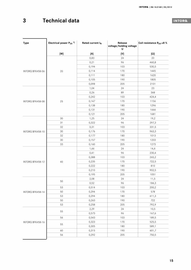
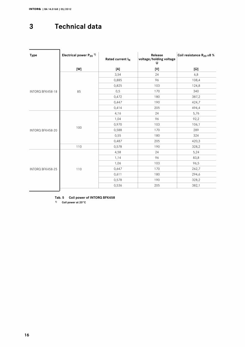
Type Electrical power P201) Rated current IN Release
voltage/holding voltageU
Coil resistance R20 ±8 %
[W] [A] [V] [Ω]
INTORQ BFK458-06 20
0,83 24 20
0,21 96 460,8
0,194 103 530,5
0,114 170 1445
0,111 180 1620
0,105 190 1805
0,098 205 2101
INTORQ BFK458-08 25
1,04 24 23
0,26 89 368
0,242 103 424,4
0,147 170 1156
0,138 180 1296
0,131 190 1444
0,121 205 1681
INTORQ BFK458-10
30 1,25 24 19,2
31 0,322 96 297,3
32 0,31 103 331,5
30 0,176 170 963,3
32 0,177 180 1013
30 0,157 190 1203
33 0,160 205 1273
INTORQ BFK458-12 40
1,66 24 14,4
0,41 96 230,4
0,388 103 265,2
0,235 170 722,5
0,222 180 810
0,210 190 902,5
0,195 205 1051
INTORQ BFK458-14
502,08 24 11,5
0,52 96 184,3
53 0,514 103 200,2
50 0,294 170 578
53 0,294 180 611,3
50 0,263 190 722
53 0,258 205 792,9
INTORQ BFK458-16
552,29 24 10,5
0,573 96 167,6
56 0,543 103 189,5
550,323 170 525,5
0,305 180 589,1
60 0,315 190 601,7
56 0,292 205 750,5
Technical data3
j | BA 14.0168 | 05/2012
16
Type Electrical power P201)
Rated current INRelease
voltage/holding voltageU
Coil resistance R20 ±8 %
[W] [A] [V] [Ω]
INTORQ BFK458-18 85
3,54 24 6,8
0,885 96 108,4
0,825 103 124,8
0,5 170 340
0,472 180 387,2
0,447 190 424,7
0,414 205 494,4
INTORQ BFK458-20100
4,16 24 5,76
1,04 96 92,2
0,970 103 106,1
0,588 170 289
0,55 180 324
0,487 205 420,3
110 0,578 190 328,2
INTORQ BFK458-25 110
4,58 24 5,24
1,14 96 83,8
1,06 103 96,5
0,647 170 262,7
0,611 180 294,6
0,578 190 328,2
0,536 205 382,1
Tab. 5 Coil power of INTORQ BFK4581) Coil power at 20_C
Technical data3 i
j | BA 14.0168 | 05/2012
17
3.4 Operating times
BFKXXX-011.iso/dms
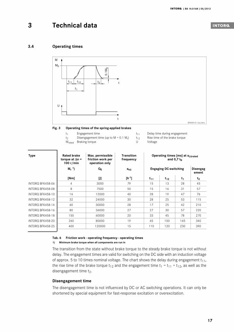
Fig. 3 Operating times of the spring-applied brakes
t1 Engagement time t11 Delay time during engagementt2 Disengagement time (up to M = 0.1 Mr) t12 Rise time of the brake torqueMrated Braking torque U Voltage
Type Rated braketorque at Δn =
100 r/min
Max. permissiblefriction work per
operation only
Transitionfrequency
Operating times [ms] at sLüratedand 0,7 IN
Mr1) QE shü Engaging DC-switching Disengag
ement
[Nm] [J] [h-1] t11 t12 t1 t2
INTORQ BFK458-06 4 3000 79 15 13 28 45
INTORQ BFK458-08 8 7500 50 15 16 31 57
INTORQ BFK458-10 16 12000 40 28 19 47 76
INTORQ BFK458-12 32 24000 30 28 25 53 115
INTORQ BFK458-14 60 30000 28 17 25 42 210
INTORQ BFK458-16 80 36000 27 27 30 57 220
INTORQ BFK458-18 150 60000 20 33 45 78 270
INTORQ BFK458-20 260 80000 19 65 100 165 340
INTORQ BFK458-25 400 120000 15 110 120 230 390
Tab. 6 Friction work - operating frequency - operating times1) Minimum brake torque when all components are run in
The transition from the state without brake torque to the steady brake torque is not withoutdelay. The engagement times are valid for switching on the DC side with an induction voltageof approx. 5 to 10 times nominal voltage. The chart shows the delay during engagement t11,the rise time of the brake torque t12 and the engagement time t1 = t11 + t12, as well as thedisengagement time t2.
Disengagement time
The disengagement time is not influenced by DC or AC switching operations. It can only beshortened by special equipment for fast-response excitation or overexcitation.
Technical data3
j | BA 14.0168 | 05/2012
18
Engagement time
With switching on the AC side, the engagement times are prolonged approximately by thefactor 10, for connection see page 32.
Spark suppressors for the rated voltages, which are to be connected in parallel to the contactare available for engagement on the DC side. If this is not admissible for safety reasons, e.g.with hoists and lifts, the spark suppressor can also be connected in parallel to the brake coil,for connection see page 33.
A reduction of the brake torque via the adjuster nut prolongs the engagement time andreduces the disengagement time. If the prolongation is too long, an anti-magnetic plate - tobe assembled between stator and armature plate - is available. The plate reduces theengagement time and prolongs the disengagement time.
Technical data3 i
j | BA 14.0168 | 05/2012
19
3.5 Operating frequency / friction work
101
102
103
104
105
10 102 103 104
252018161412
1008
06
Operating frequency Sh[h-1]
Fric
tion
wor
kQ
[J]
Sizes
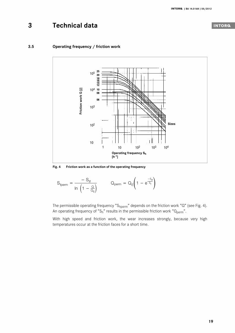
Fig. 4 Friction work as a function of the operating frequency
pÑéÉêã=− píÑ
äå N− nnb néÉêã= nbN− É
−píÑpÑ
The permissible operating frequency ”Shperm” depends on the friction work ”Q” (see Fig. 4).An operating frequency of ”Sh” results in the permissible friction work ”Qperm”.
With high speed and friction work, the wear increases strongly, because very hightemperatures occur at the friction faces for a short time.
Technical data3
j | BA 14.0168 | 05/2012
20
3.6 Emission
Electromagnetic compatibility
Note!The user must ensure compliance with EMC Directive 2004/108/EC usingappropriate controls and switching devices.
If an INTORQ rectifier is used for the DC switching of an INTORQ spring-applied brake andif the operating frequency exceeds five switching operations per minute, the use of amains filter is required. If the INTORQ spring-applied brake uses a rectifier of anothermanufacturer for the switching, it may become necessary to connect a spark suppressorin parallel with the AC voltage. Spark suppressor according to coil voltage on request.
Heat
Since the brake converts kinetic energy as well as mechanical and electrical energy into heat,the surface temperature varies considerably, depending on the operating conditions andpossible heat dissipation. Under unfavourable conditions, the surface temperature can reach130_C.
Noises
The switching noises during engagement and disengagement depend on the air gap ”sair” andthe brake size.
Depending on the natural oscillation after installation, operating conditions and state of thefriction faces, the brake may squeak during braking.
Others
The abrasion of the friction parts produces dust.
In case of high load, the friction face will become so hot that odours may occur.
Mechanical installation4 i
j | BA 14.0168 | 05/2012
21
4 Mechanical installation
Stop!Toothed hub and screws must not be lubricated with grease or oil!
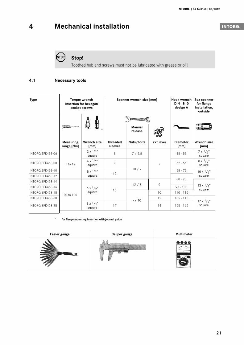
4.1 Necessary tools
Type Torque wrenchInsertion for hexagon
socket screws
Spanner wrench size [mm] Hook wrenchDIN 1810design A
Box spannerfor flange
installation,outside
*Manualrelease
Measuringrange [Nm]
Wrench size[mm]
Threadedsleeves
Nuts/bolts 2kt lever Diameter[mm]
Wrench size[mm]
INTORQ BFK458-06
1 to 12
3 x 1/4”square 8 7 / 5,5
7
45 - 55 7 x 1/2”square
INTORQ BFK458-08 4 x 1/4”square 9
10 / 7
52 - 55 8 x 1/2”square
INTORQ BFK458-10 5 x 1/4”square 12
68 - 75 10 x 1/2”squareINTORQ BFK458-12
80 - 90INTORQ BFK458-14
20 to 100
6 x 1/2”square 15
12 / 8 9 13 x 1/2”square
INTORQ BFK458-16 95 - 100
INTORQ BFK458-18
- / 10
10 110 - 115square
INTORQ BFK458-20 12 135 - 14517 x 1/2”
squareINTORQ BFK458-25 8 x 1/2”square 17 14 155 - 165
* for flange mounting insertion with journal guide
Feeler gauge Caliper gauge Multimeter
Mechanical installation4
j | BA 14.0168 | 05/2012
22
4.2 Mounting
4.2.1 Preparation
1. Unpack spring-applied brake.
2. Check for completeness.
3. Check nameplate data, especially rated voltage.
4.3 Installation
When you have ordered a version with manual release or flange, attach these units first.
4.3.1 Installation of the hub onto the shaft
15
4
4.1
K14.0502/1
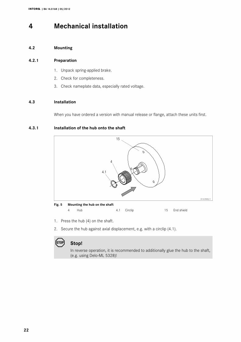
Fig. 5 Mounting the hub on the shaft
4 Hub 4.1 Circlip 15 End shield
1. Press the hub (4) on the shaft.
2. Secure the hub against axial displacement, e.g. with a circlip (4.1).
Stop!In reverse operation, it is recommended to additionally glue the hub to the shaft,(e.g. using Delo-ML 5328)!
Mechanical installation4 i
j | BA 14.0168 | 05/2012
23
4.3.2 Installation of the brake
Stop!| When dimensioning the thread depth in the endshield, consider the
permissible wear (chapter 3.3).| Check the condition of the endshield (15). It must be free of oil and grease.
3
4
15
K14.0502/8
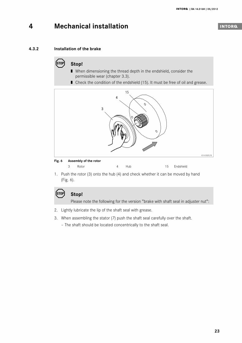
Fig. 6 Assembly of the rotor
3 Rotor 4 Hub 15 Endshield
1. Push the rotor (3) onto the hub (4) and check whether it can be moved by hand(Fig. 6).
Stop!Please note the following for the version ”brake with shaft seal in adjuster nut”:
2. Lightly lubricate the lip of the shaft seal with grease.
3. When assembling the stator (7) push the shaft seal carefully over the shaft.
– The shaft should be located concentrically to the shaft seal.
Mechanical installation4
j | BA 14.0168 | 05/2012
24
7
10
1511
KL458-011-a
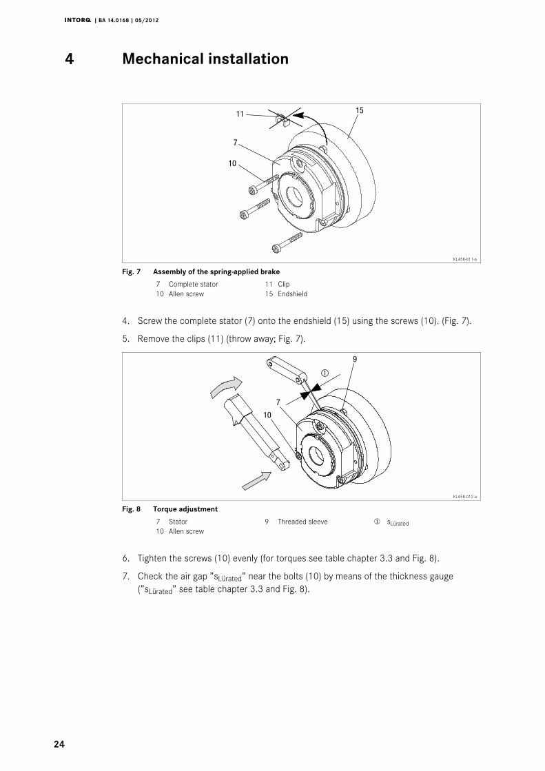
Fig. 7 Assembly of the spring-applied brake
7 Complete stator 11 Clip10 Allen screw 15 Endshield
4. Screw the complete stator (7) onto the endshield (15) using the screws (10). (Fig. 7).
5. Remove the clips (11) (throw away; Fig. 7).
9
7
10
KL458-012-a
Fig. 8 Torque adjustment
7 Stator 9 Threaded sleeve sLürated10 Allen screw
6. Tighten the screws (10) evenly (for torques see table chapter 3.3 and Fig. 8).
7. Check the air gap ”sLürated” near the bolts (10) by means of the thickness gauge(”sLürated” see table chapter 3.3 and Fig. 8).
Mechanical installation4 i
j | BA 14.0168 | 05/2012
25
H
J9
7
10
KL458-013-a
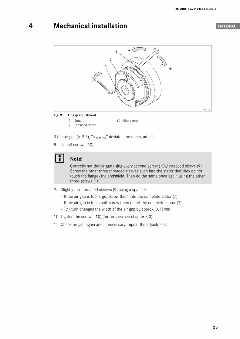
Fig. 9 Air gap adjustment
7 Stator 10 Allen screw9 Threaded sleeve
If the air gap (s. 3.3), ”sLü rated” deviates too much, adjust:
8. Unbolt screws (10).
Note!Correctly set the air gap using every second screw (10)/threaded sleeve (9)!Screw the other three threaded sleeves such into the stator that they do nottouch the flange/the endshield. Then do the same once again using the otherthree screws (10).
9. Slightly turn threaded sleeves (9) using a spanner.
– If the air gap is too large, screw them into the complete stator (7).
– If the air gap is too small, screw them out of the complete stator (7).
– 1/6 turn changes the width of the air gap by approx. 0.15mm.
10. Tighten the screws (10) (for torques see chapter 3.3).
11. Check air gap again and, if necessary, repeat the adjustment.
Mechanical installation4
j | BA 14.0168 | 05/2012
26
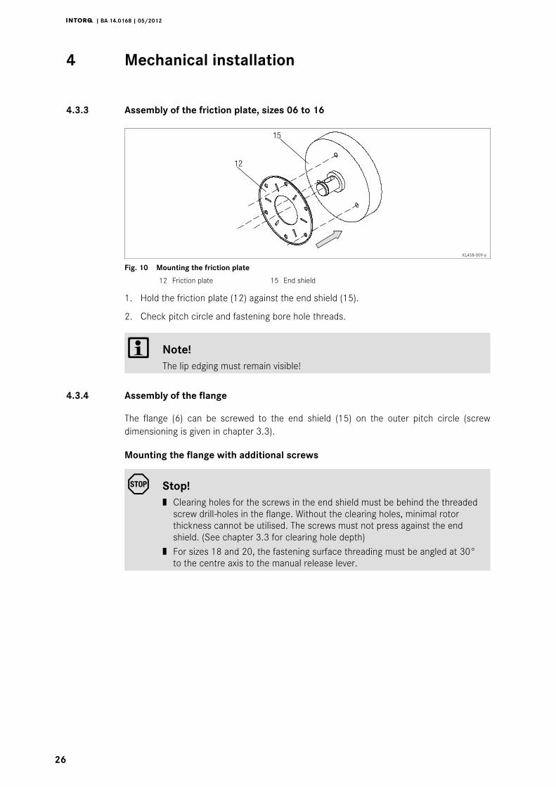
4.3.3 Assembly of the friction plate, sizes 06 to 16
15
12
KL458-009-a
Fig. 10 Mounting the friction plate
12 Friction plate 15 End shield
1. Hold the friction plate (12) against the end shield (15).
2. Check pitch circle and fastening bore hole threads.
Note!The lip edging must remain visible!
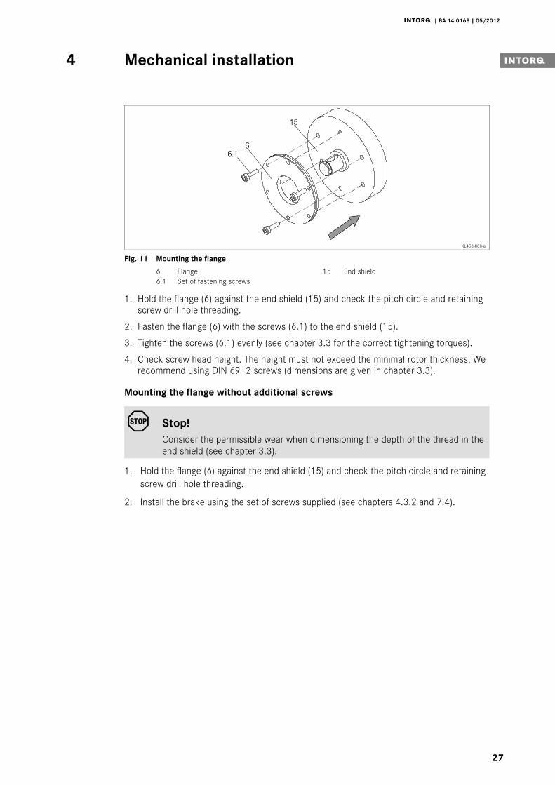
4.3.4 Assembly of the flange
The flange (6) can be screwed to the end shield (15) on the outer pitch circle (screwdimensioning is given in chapter 3.3).
Mounting the flange with additional screws
Stop!| Clearing holes for the screws in the end shield must be behind the threaded
screw drill-holes in the flange. Without the clearing holes, minimal rotorthickness cannot be utilised. The screws must not press against the endshield. (See chapter 3.3 for clearing hole depth)
| For sizes 18 and 20, the fastening surface threading must be angled at 30°to the centre axis to the manual release lever.
Mechanical installation4 i
j | BA 14.0168 | 05/2012
27
15
66.1
KL458-008-a
Fig. 11 Mounting the flange
6 Flange 15 End shield6.1 Set of fastening screws
1. Hold the flange (6) against the end shield (15) and check the pitch circle and retainingscrew drill hole threading.
2. Fasten the flange (6) with the screws (6.1) to the end shield (15).
3. Tighten the screws (6.1) evenly (see chapter 3.3 for the correct tightening torques).
4. Check screw head height. The height must not exceed the minimal rotor thickness. Werecommend using DIN 6912 screws (dimensions are given in chapter 3.3).
Mounting the flange without additional screws
Stop!Consider the permissible wear when dimensioning the depth of the thread in theend shield (see chapter 3.3).
1. Hold the flange (6) against the end shield (15) and check the pitch circle and retainingscrew drill hole threading.
2. Install the brake using the set of screws supplied (see chapters 4.3.2 and 7.4).
Mechanical installation4
j | BA 14.0168 | 05/2012
28
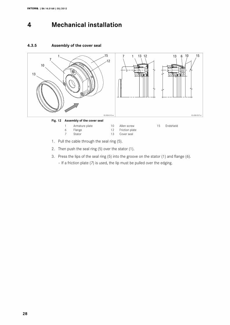
4.3.5 Assembly of the cover seal
15
13
1210
71 7 1 15613 12 13 10
KL458-010-a KL458-007-a
Fig. 12 Assembly of the cover seal
1 Armature plate 10 Allen screw 15 Endshield6 Flange 12 Friction plate7 Stator 13 Cover seal
1. Pull the cable through the seal ring (5).
2. Then push the seal ring (5) over the stator (1).
3. Press the lips of the seal ring (5) into the groove on the stator (1) and flange (6).
– If a friction plate (7) is used, the lip must be pulled over the edging.
Mechanical installation4 i
j | BA 14.0168 | 05/2012
29
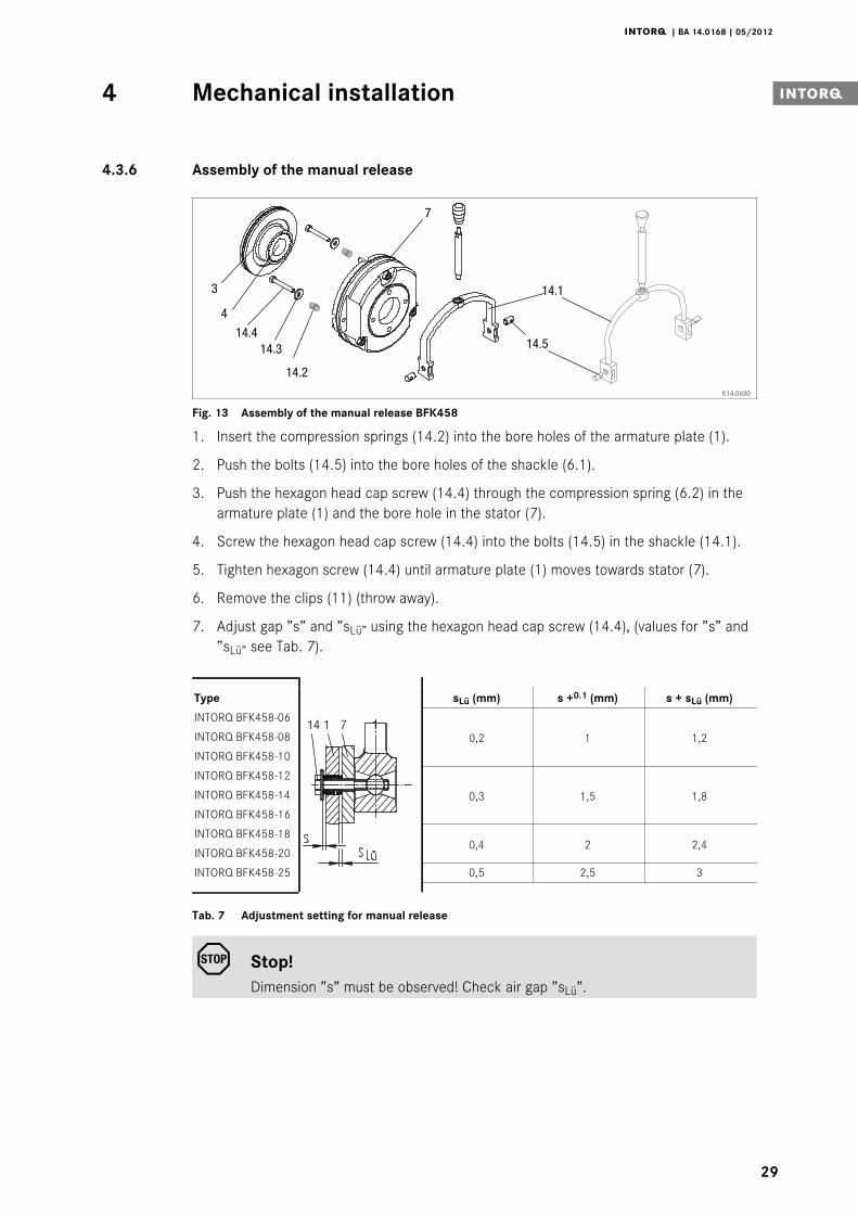
4.3.6 Assembly of the manual release
4
14.3
14.2
14.4
3
7
14.5
14.1
K14.0630
Fig. 13 Assembly of the manual release BFK458
1. Insert the compression springs (14.2) into the bore holes of the armature plate (1).
2. Push the bolts (14.5) into the bore holes of the shackle (6.1).
3. Push the hexagon head cap screw (14.4) through the compression spring (6.2) in thearmature plate (1) and the bore hole in the stator (7).
4. Screw the hexagon head cap screw (14.4) into the bolts (14.5) in the shackle (14.1).
5. Tighten hexagon screw (14.4) until armature plate (1) moves towards stator (7).
6. Remove the clips (11) (throw away).
7. Adjust gap ”s” and ”sLü” using the hexagon head cap screw (14.4), (values for ”s” and”sLü” see Tab. 7).
Type
114 71
sLü (mm) s +0.1 (mm) s + sLü (mm)
INTORQ BFK458-06
0,2 1 1,2INTORQ BFK458-08
INTORQ BFK458-10
INTORQ BFK458-12
0,3 1,5 1,8INTORQ BFK458-14
INTORQ BFK458-16
INTORQ BFK458-180,4 2 2,4
INTORQ BFK458-20
INTORQ BFK458-25 0,5 2,5 3
Tab. 7 Adjustment setting for manual release
Stop!Dimension ”s” must be observed! Check air gap ”sLü”.
Electrical installation5
j | BA 14.0168 | 05/2012
30
5 Electrical installation
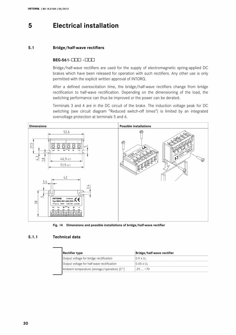
5.1 Bridge/half-wave rectifiers
BEG-561- -Bridge/half-wave rectifiers are used for the supply of electromagnetic spring-applied DCbrakes which have been released for operation with such rectifiers. Any other use is onlypermitted with the explicit written approval of INTORQ.
After a defined overexcitation time, the bridge/half-wave rectifiers change from bridgerectification to half-wave rectification. Depending on the dimensioning of the load, theswitching performance can thus be improved or the power can be derated.
Terminals 3 and 4 are in the DC circuit of the brake. The induction voltage peak for DCswitching (see circuit diagram ”Reduced switch-off times”) is limited by an integratedovervoltage protection at terminals 5 and 6.
Dimensions Possible installations
3,4
38
4
42
3,4
52,6
21,5
1,84,3
46,9-0,1
51,9-0,1
440V~ 1,5/0,75A t =0,30sü
13169140
Typ BEG-561-440-030-1
5
Fig. 14 Dimensions and possible installations of bridge/half-wave rectifier
5.1.1 Technical data
Rectifier type Bridge/half-wave rectifier
Output voltage for bridge rectification 0.9 x U1
Output voltage for half-wave rectification 0.45 x U1
Ambient temperature (storage/operation) [C°] -25 ... +70
Electrical installation5 i
j | BA 14.0168 | 05/2012
31
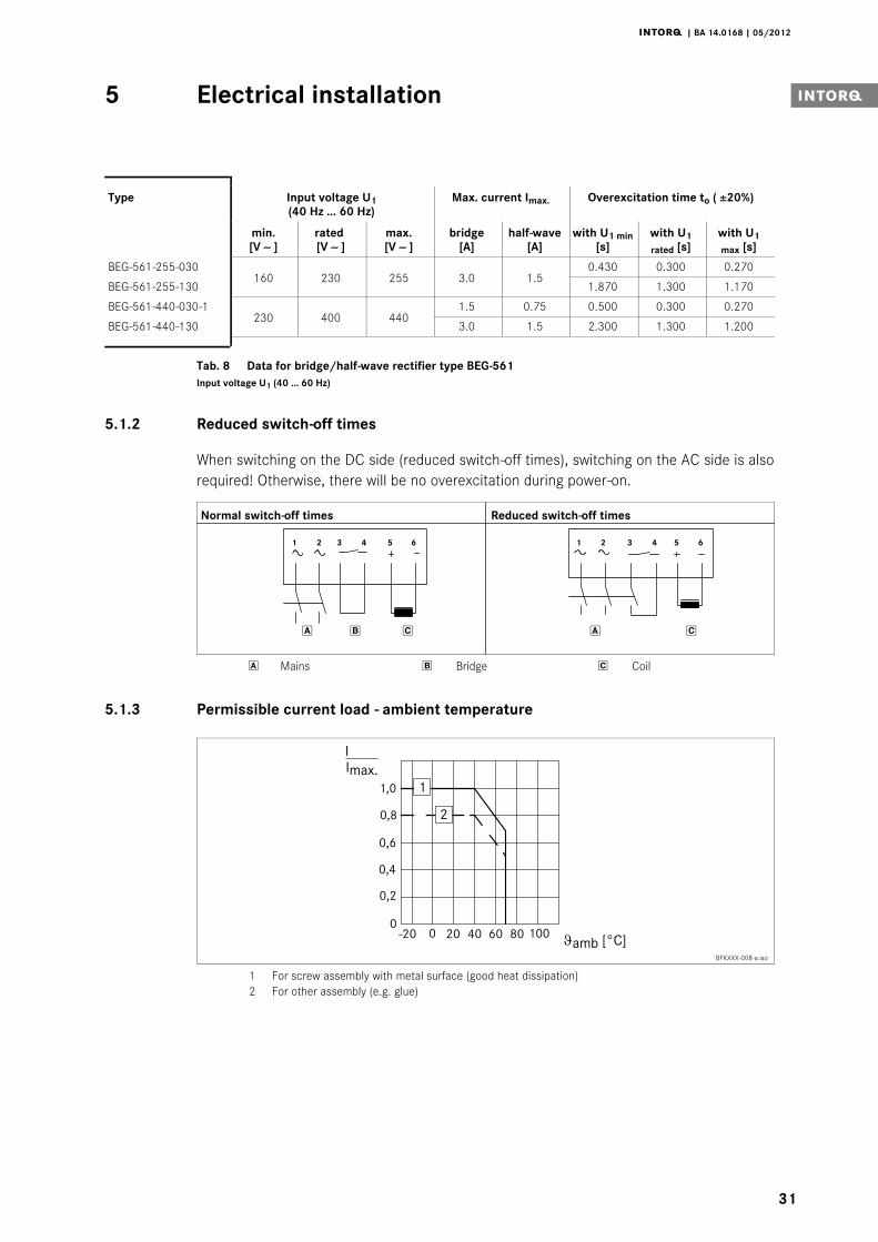
Type Input voltage U1(40 Hz ... 60 Hz)
Max. current Imax. Overexcitation time to ( ±20%)
min.[V ∼ ]
rated[V ∼ ]
max.[V ∼ ]
bridge[A]
half-wave[A]
with U1 min[s]
with U1rated [s]
with U1max [s]
BEG-561-255-030160 230 255 3.0 1.5
0.430 0.300 0.270
BEG-561-255-130 1.870 1.300 1.170
BEG-561-440-030-1230 400 440
1.5 0.75 0.500 0.300 0.270
BEG-561-440-130 3.0 1.5 2.300 1.300 1.200
Tab. 8 Data for bridge/half-wave rectifier type BEG-561Input voltage U1 (40 ... 60 Hz)
5.1.2 Reduced switch-off times
When switching on the DC side (reduced switch-off times), switching on the AC side is alsorequired! Otherwise, there will be no overexcitation during power-on.
Normal switch-off times Reduced switch-off times
1 2 3 4 65
1 2 3 4 65
Mains Bridge Coil
5.1.3 Permissible current load - ambient temperature
BFKXXX-008-a.iso
1 For screw assembly with metal surface (good heat dissipation)2 For other assembly (e.g. glue)
Electrical installation5
j | BA 14.0168 | 05/2012
32
5.1.4 Assignment: Bridge/half-wave rectifier - brake size
Rectifier type AC voltage Coil voltagerelease/holding Assigned brake
[V AC] [V DC]
BEG-561-255-030230 ±10% 205 / 103
BFK458-06...25BEG-561-255-130
BEG-561-440-030-1400 ±10% 360 / 180
BEG-561-440-130
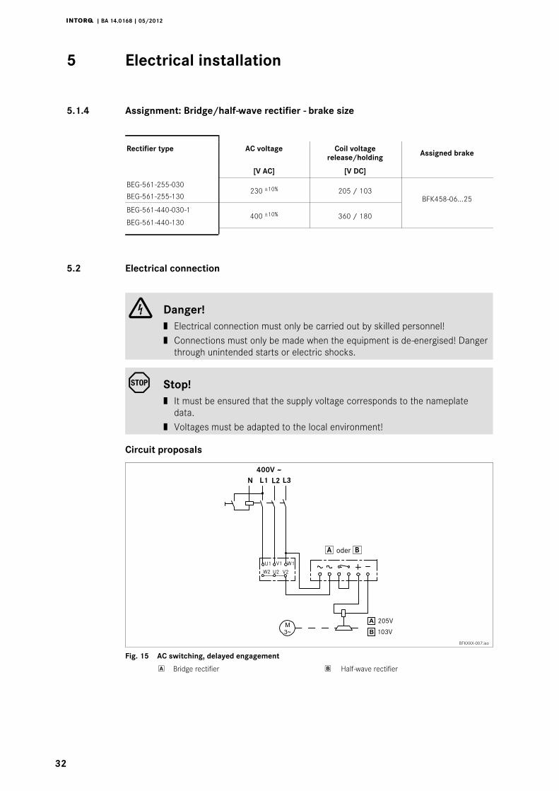
5.2 Electrical connection
Danger!| Electrical connection must only be carried out by skilled personnel!| Connections must only be made when the equipment is de-energised! Danger
through unintended starts or electric shocks.
Stop!| It must be ensured that the supply voltage corresponds to the nameplate
data.| Voltages must be adapted to the local environment!
Circuit proposals
BFKXXX-007.iso
Fig. 15 AC switching, delayed engagement
Bridge rectifier Half-wave rectifier
Electrical installation5 i
j | BA 14.0168 | 05/2012
33
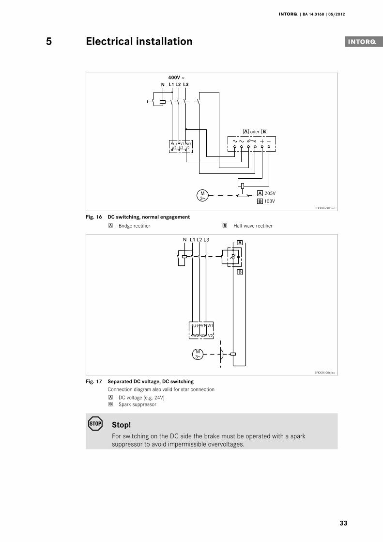
BFKXXX-002.iso
Fig. 16 DC switching, normal engagement
Bridge rectifier Half-wave rectifier
BFKXXX-006.iso
Fig. 17 Separated DC voltage, DC switchingConnection diagram also valid for star connection
DC voltage (e.g. 24V) Spark suppressor
Stop!For switching on the DC side the brake must be operated with a sparksuppressor to avoid impermissible overvoltages.
Electrical installation5
j | BA 14.0168 | 05/2012
34
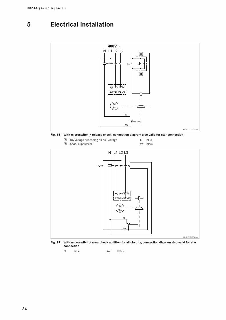
KL-BFKXXX-003.iso
Fig. 18 With microswitch / release check; connection diagram also valid for star connection
DC voltage depending on coil voltage bl blue Spark suppressor sw black
KL-BFKXXX-004.iso
Fig. 19 With microswitch / wear check addition for all circuits; connection diagram also valid for starconnection
bl blue sw black
Electrical installation5 i
j | BA 14.0168 | 05/2012
35
Tip!During operation according to Fig. 19 the air gap is only monitored when no voltage is appliedto the brake. This makes sense because it is possible that when the current flows only oneside of the armature plate is attracted at first. This misalignment may cause a simulation of themaximum air gap and the actuation of the microswitch. If there is no closed contact in parallelto the microswitch contact, motor and brake will be switched off. The microswitch contact isclosed again when the armature plate is completely released - the release is repeated again -because of the small difference-contact travel of the microswitch.To avoid this misinterpretation of the microswitch signal, the signal should only be processedwhen no voltage is applied to the brake.
1. Mount the rectifier in the terminal box. With motors of the insulation class ”H”, therectifier must be mounted in the control cabinet. Permissible ambient temperature forthe rectifier -25_C to +70_C.
2. Compare the coil voltage of the stator to the DC voltage of the installed rectifier.
3. Select the suitable circuit diagram. Convert the values to deviating AC voltage, e.g.380V,
380/400x205 = 195V
– Deviations up to 3% are permissible.
Note!Selection of the rectifier at voltages ≥ 460 V AC catalogue ”Electronicswitchgear and accessories” Chapter spark suppressors and rectifiers.
4. Motor and brake must be wired according to the requirements of the engagementtime.
Commissioning and operation6
j | BA 14.0168 | 05/2012
36
6 Commissioning and operation
Danger!The live connections and the rotating rotor must not be touched.The drive must not be running when checking the brake.
6.1 Functional test
In the event of failures, refer to the troubleshooting table in chapter 8. If the fault cannot beeliminated, please contact the aftersales service.
6.1.1 Release / voltage check
For brakes without microswitch only
Danger!The brake must be free of residual torque. The motor must not rotate.
Danger!Live connections must not be touched.
1. Remove two bridges from the motor terminals. Do not switch off the DC brake supply.When connecting the rectifier to the neutral point of the motor, the PE conductor mustalso be connected to this point.
2. Connect the mains supply.
3. Measure the DC voltage at the brake.
– Compare the DC voltage measured with the voltage specified on the nameplate.A ± 10 % deviation is permissible.
4. Check air gap ”sLü”. It must be zero and the rotor must rotate freely.
5. Switch off the power supply.
6. Bolt bridges to the motor terminals. Remove additional PEN conductor.
Commissioning and operation6 i
j | BA 14.0168 | 05/2012
37
6.1.2 Microswitch - release check
Danger!The brake must be free of residual torque. The motor must not rotate.
Danger!Live connections must not be touched.
Connection diagram: (see page 32)
1. Remove two bridges from the motor terminals.
– Do not switch off the DC brake supply.
2. The switching contact for the brake must be open.
3. Apply DC voltage to the brake.
4. Measure the AC voltage at the motor terminals. It must be zero.
5. Close the switching contact for the brake.
6. Measure the DC voltage at the brake:
– The DC voltage measured after the overexcitation time (see bridge/half-waverectifier, chapter 5.1) must correspond to the holding voltage (see Tab. 8). A 10 %deviation is permissible.
7. Check air gap ”sLü”.
– It must be zero and the rotor must rotate freely.
8. Open the switching contact for the brake.
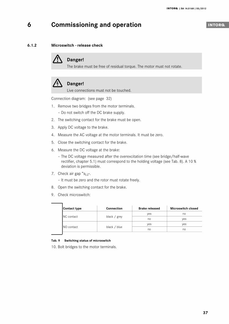
9. Check microswitch:
Contact type Connection Brake released Microswitch closed
NC contact black / greyyes no
no yes
NO contact black / blueyes yes
no no
Tab. 9 Switching status of microswitch
10. Bolt bridges to the motor terminals.
Commissioning and operation6
j | BA 14.0168 | 05/2012
38
6.1.3 Microswitch - wear check
Danger!The brake must be free of residual torque. The motor must not rotate.
Danger!Live connections must not be touched.
1. Remove two bridges from the motor terminals. Do not switch off the DC voltage forthe brake. When connecting the rectifier to the neutral point of the motor, the PEconductor must also be connected to this point.
2. Set air gap to ”sLümax.”. See chapter 4.3.2 Step 8-11.
3. Connect the mains supply.
4. Measure the AC voltage at the motor terminals and the DC voltage at the brake. Bothmust be zero.
5. Disconnect the mains supply.
6. Set air gap to ”sLürated”. See chapter 4.3.2 Step 8-11.
7. Connect the mains supply.
8. Measure the AC voltage at the motor terminals. It must be the same as the mainsvoltage.
9. Measure the DC voltage at the brake.
– The DC voltage measured after the overexcitation time (see bridge/half-waverectifier) must be half the voltage indicated on the nameplate. A 10 % deviation ispermissible.
10. Check air gap ”sLü”. It must be zero and the rotor must rotate freely.
11. Switch off the current for the brake.
12. Bolt bridges to the motor terminals. Remove additional PEN conductor.
6.1.4 Manual release
Stop!This operational test is to be carried out additionally!
Danger!The brake must be free of residual torque. The motor must not rotate.
Commissioning and operation6 i
j | BA 14.0168 | 05/2012
39
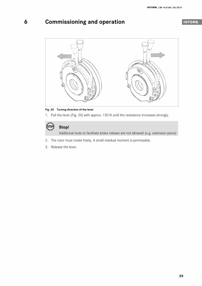
Fig. 20 Turning direction of the lever
1. Pull the lever (Fig. 20) with approx. 150 N until the resistance increases strongly.
Stop!Additional tools to facilitate brake release are not allowed! (e.g. extension piece)
2. The rotor must rotate freely. A small residual moment is permissible.
3. Release the lever.
Commissioning and operation6
j | BA 14.0168 | 05/2012
40
6.2 Reducing the brake torque
h1max.
8
7
M-
M+
KL458-003-a KL458-006-a
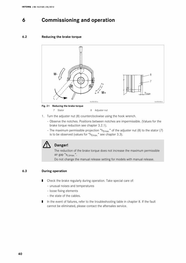
Fig. 21 Reducing the brake torque
7 Stator 8 Adjuster nut
1. Turn the adjuster nut (8) counterclockwise using the hook wrench.
– Observe the notches. Positions between notches are impermissible. (Values for thebrake torque reduction see chapter 3.2.1).
– The maximum permissible projection ”hEmax.” of the adjuster nut (8) to the stator (7)is to be observed (values for ”hEmax.” see chapter 3.3).
Danger!The reduction of the brake torque does not increase the maximum permissibleair gap ”sLümax.”.Do not change the manual release setting for models with manual release.
6.3 During operation
| Check the brake regularly during operation. Take special care of:
– unusual noises and temperatures
– loose fixing elements
– the state of the cables.
| In the event of failures, refer to the troubleshooting table in chapter 8. If the faultcannot be eliminated, please contact the aftersales service.
Maintenance/repair7 i
j | BA 14.0168 | 05/2012
41
7 Maintenance/repair
7.1 Wear of spring-applied brakes
INTORQ spring-applied brakes are wear-resistant and designed for long maintenanceintervals. The friction lining and the mechanical brake components are subject tofunction-related wear. For safe and trouble-free operation, the brake must be checked andreadjusted at regular intervals, and, if necessary, be replaced.
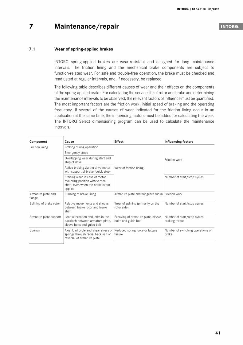
The following table describes different causes of wear and their effects on the componentsof the spring-applied brake. For calculating the service life of rotor and brake and determiningthe maintenance intervals to be observed, the relevant factors of influence must be quantified.The most important factors are the friction work, initial speed of braking and the operatingfrequency. If several of the causes of wear indicated for the friction lining occur in anapplication at the same time, the influencing factors must be added for calculating the wear.The INTORQ Select dimensioning program can be used to calculate the maintenanceintervals.
Component Cause Effect Influencing factors
Friction lining Braking during operation
Wear of friction lining
Friction work
Emergency stops
Overlapping wear during start andstop of drive
Active braking via the drive motorwith support of brake (quick stop)
Starting wear in case of motormounting position with verticalshaft, even when the brake is notapplied
Number of start/stop cycles
Armature plate andflange
Rubbing of brake lining Armature plate and flangeare run in Friction work
Splining of brake rotor Relative movements and shocksbetween brake rotor and brakeshaft
Wear of splining (primarily on therotor side)
Number of start/stop cycles
Armature plate support Load alternation and jerks in thebacklash between armature plate,sleeve bolts and guide bolt
Breaking of armature plate, sleevebolts and guide bolt
Number of start/stop cycles,braking torque
Springs Axial load cycle and shear stress ofsprings through radial backlash onreversal of armature plate
Reduced spring force or fatiguefailure
Number of switching operations ofbrake
Maintenance/repair7
j | BA 14.0168 | 05/2012
42
7.2 Inspections
To ensure safe and trouble-free operation, spring-applied brakes must be checked andmaintained at regular intervals. Servicing can be made easier if good accessability of thebrakes is provided in the plant. This must be considered when installing the drives in the plant.
Primarily, the necessary maintenance intervals for industrial brakes result from the load duringoperation. When calculating the maintenance interval, all causes for wear must be taken intoaccount (see chapter 7.1). For brakes with low loads such as holding brakes with emergencystop, we recommend a regular inspection at a fixed time interval. To reduce the cost, theinspection can be carried out along with other regular maintenance work in the plant ifnecessary.
If the brakes are not maintained, failures, production outages or plant damages may be theresult. Thus, a maintenance concept adapted to the operating conditions and loads of thebrake must be developed for every application. The maintenance intervals and maintenancework listed in the following table must be scheduled for the spring-applied INTORQ brake.
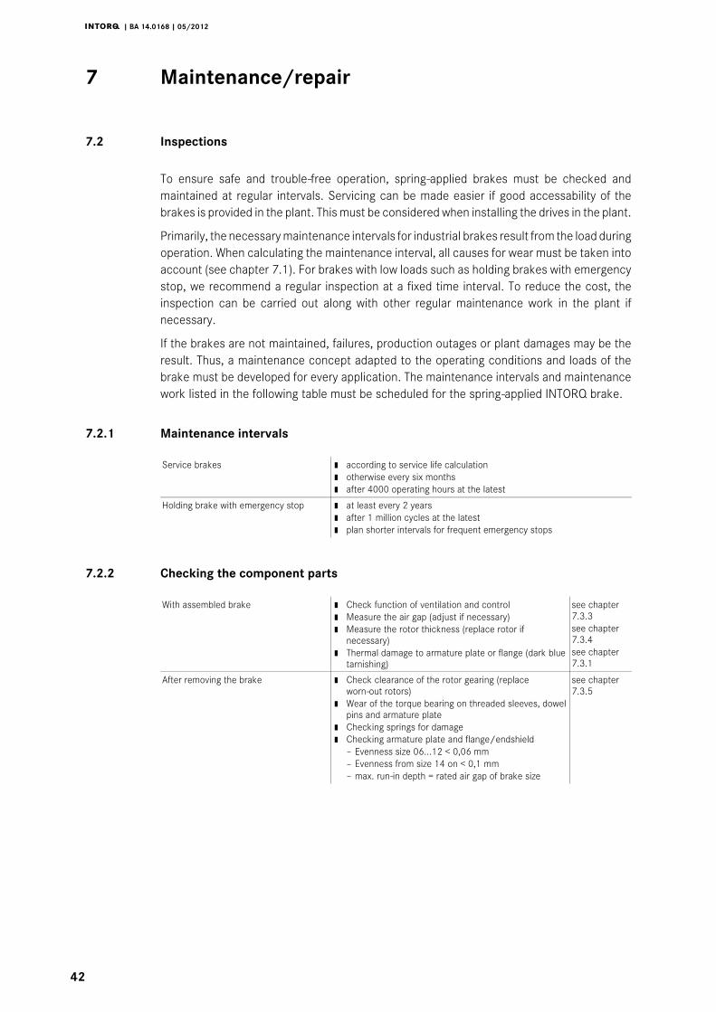
7.2.1 Maintenance intervals
Service brakes | according to service life calculation| otherwise every six months| after 4000 operating hours at the latest
Holding brake with emergency stop | at least every 2 years| after 1 million cycles at the latest| plan shorter intervals for frequent emergency stops
7.2.2 Checking the component parts
With assembled brake | Check function of ventilation and control| Measure the air gap (adjust if necessary)| Measure the rotor thickness (replace rotor if
necessary)| Thermal damage to armature plate or flange (dark blue
tarnishing)
see chapter7.3.3see chapter7.3.4see chapter7.3.1
After removing the brake | Check clearance of the rotor gearing (replaceworn-out rotors)
| Wear of the torque bearing on threaded sleeves, dowelpins and armature plate
| Checking springs for damage| Checking armature plate and flange/endshield
– Evenness size 06...12 < 0,06 mm– Evenness from size 14 on < 0,1 mm– max. run-in depth = rated air gap of brake size
see chapter7.3.5
Maintenance/repair7 i
j | BA 14.0168 | 05/2012
43
7.3 Maintenance
Note!Brakes with defective armature plates, cheese head screws, springs or flangesmust be replaced completely.Please observe the following for inspections and maintenance operations:| Remove impurities through oil and grease using brake cleaning agents, if
necessary, replace brake after finding out the cause of the contamination.Dirt deposits in the air gap between stator and armature plate impair thefunction of the brake and must be removed.
| After replacing the rotor, the original braking torque will not be reached untilthe run-in operation of the friction surfaces has been completed. Afterreplacing the rotor, run-in armature plates and flanges have an increasedinitial rate of wear.
7.3.1 Checking the rotor thickness
Danger!The motor must not be running when checking the motor thickness.
1. Remove the motor cover and seal ring (if mounted).
2. Measure the rotor thickness with a caliper gauge. On brakes with friction plates,observe edging on outer diameter of friction plate.
3. Compare measured rotor thickness with minimally permissible rotor thickness (seechapter 3.3 for applicable values).
4. Replace the complete rotor if necessary. See chapter 7.3.5 for description.
7.3.2 Check air gap
1. Measure the air gap ”sLü” between armature plate and rotor using a feeler gauge (seechapter 3.3).
2. Compare the measured air gap to the maximum permissible air gap ”sLümax.” (seetable chapter 3.3).
3. If necessary, adjust air gap to ”sLürated”. See chapter 7.3.4.
Maintenance/repair7
j | BA 14.0168 | 05/2012
44
7.3.3 Release / voltage
Danger!The running rotor must not be touched.
Danger!Live connections must not be touched.
1. Observe the brake function during operation of the drive. The armature plate must beattracted and the rotor must move without residual torque.
2. Measure the DC voltage at the brake.
– The DC voltage measured after the overexcitation time (see bridge/half-waverectifier, chapter 5.1.4) must correspond to the holding voltage. A 10 % deviation ispermissible.
7.3.4 Readjustment of air gap
Danger!Disconnect voltage. The brake must be free of residual torque.
Stop!Observe for the flange version when it is fixed with additional screws:Behind the threaded holes for the screws in the flange there must be clearingholes in the endshield. Without clearing holes the minimum rotor thicknesscannot be used. Under no circumstances may the screws be pressed againstthe endshield.
1. Unbolt screws (Fig. 9).
2. Screw the threaded sleeves into the stator by using a spanner. 1/6 revolution reducesthe air gap by approx. 0.15 mm.
3. Tighten screws (for torques see table chapter 3.3).
4. Check the air gap ”sLü” near the screws using a feeler gauge (”sLürated” see tablechapter 3.3).
5. If the difference between the measured air gap and ”sLürated” is too large, repeat thereadjustment.
Maintenance/repair7 i
j | BA 14.0168 | 05/2012
45
7.3.5 Rotor replacement
Danger!Disconnect voltage. The brake must be free of residual torque.
1. Loosen connection cable.
2. Loosen the screws evenly and remove them.
3. Completely remove the stator from the end shield. Observe the supply cable.
4. Pull rotor from hub.
5. Check hub toothing.
6. In case of wear, the hub must also be replaced.
7. Check the friction surface at the end shield. In case of strong scoring at the flange,replace the flange. If scoring occurs at the end shield, re-finish end shield.
8. Measure the rotor thickness (new rotor) and head height of the threaded sleeves usinga caliper gauge.
9. Calculate the distance between stator and armature plate as follows:
Distance = Rotor thickness + sLürated - head height
(”sLürated” see table chapter 3.3 )
10. Evenly loosen the threaded sleeves until the calculated distance between stator andarmature plate is reached.
11. Install and adjust new rotor and stator (see chapter 4.3.2).
12. Reconnect the supply cable.
Maintenance/repair7
j | BA 14.0168 | 05/2012
46
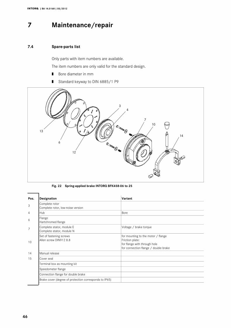
7.4 Spare-parts list
Only parts with item numbers are available.
The item numbers are only valid for the standard design.
| Bore diameter in mm
| Standard keyway to DIN 6885/1 P9
13
6
12
34
14
107
Fig. 22 Spring-applied brake INTORQ BFK458-06 to 25
Pos. Designation Variant
3 Complete rotorComplete rotor, low-noise version
4 Hub Bore
6 FlangeHartchromed flange
7 Complete stator, module EComplete stator, module N
Voltage / brake torque
10
Set of fastening screwsAllen screw DIN912 8.8
for mounting to the motor / flangeFriction plate:for flange with through holefor connection flange / double brake
14 Manual release
15 Cover seal
Terminal box as mounting kit
Speedometer flange
Connection flange for double brake
Brake cover (degree of protection corresponds to IP65)
Maintenance/repair7 i
j | BA 14.0168 | 05/2012
47
7
9
1
3
111210
7
238
4
106 5
2
41
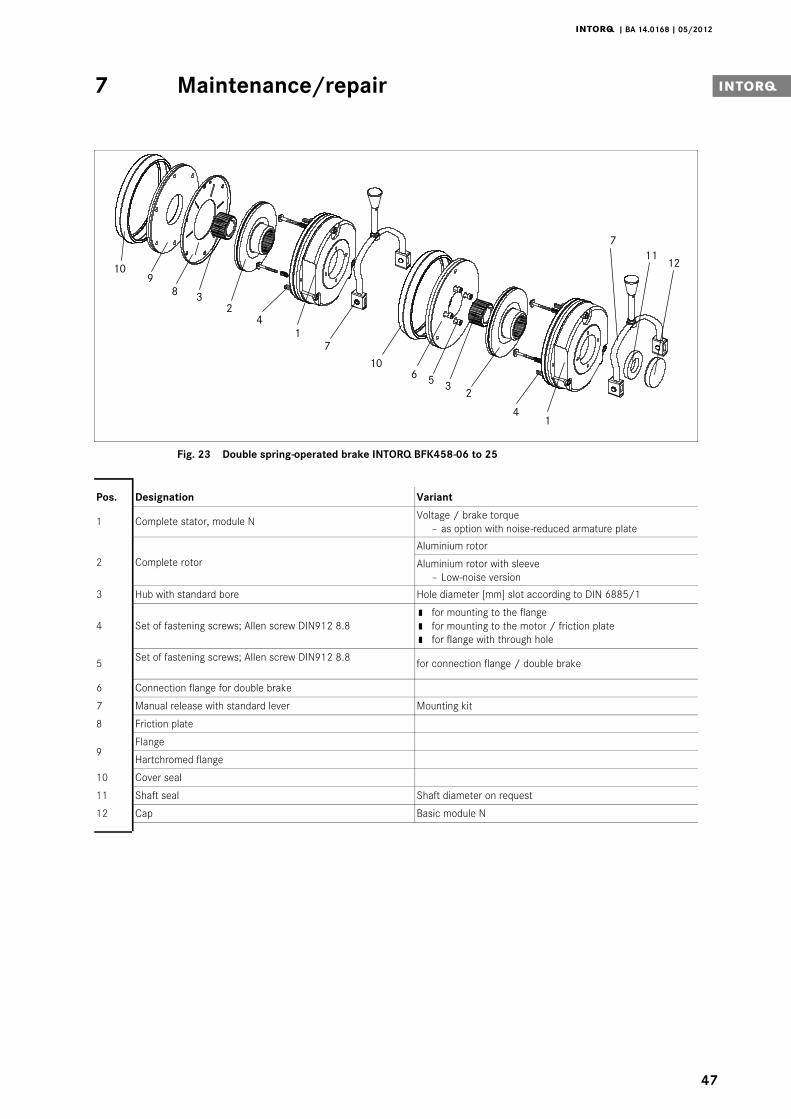
Fig. 23 Double spring-operated brake INTORQ BFK458-06 to 25
Pos. Designation Variant
1 Complete stator, module N Voltage / brake torque– as option with noise-reduced armature plate
2 Complete rotor
Aluminium rotor
Aluminium rotor with sleeve– Low-noise version
3 Hub with standard bore Hole diameter [mm] slot according to DIN 6885/1
4 Set of fastening screws; Allen screw DIN912 8.8| for mounting to the flange| for mounting to the motor / friction plate| for flange with through hole
5 Set of fastening screws; Allen screw DIN912 8.8 for connection flange / double brake
6 Connection flange for double brake
7 Manual release with standard lever Mounting kit
8 Friction plate
9Flange
Hartchromed flange
10 Cover seal
11 Shaft seal Shaft diameter on request
12 Cap Basic module N
Maintenance/repair7
j | BA 14.0168 | 05/2012
48
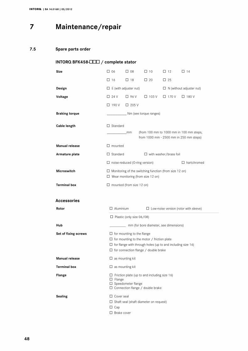
7.5 Spare parts order
INTORQ BFK458- / complete stator
Size 06 08 10 12 14
16 18 20 25
Design E (with adjuster nut) N (without adjuster nut)
Voltage 24 V 96 V 103 V 170 V 180 V
190 V 205 V
Braking torque ___________ Nm (see torque ranges)
Cable length Standard
___________mm (from 100 mm to 1000 mm in 100 mm steps,
from 1000 mm - 2500 mm in 250 mm steps)
Manual release mounted
Armature plate Standard with washer/brass foil
noise-reduced (O-ring version) hartchromed
Microswitch Monitoring of the switching function (from size 12 on)
Wear monitoring (from size 12 on)
Terminal box mounted (from size 12 on)
Accessories
Rotor Aluminium Low-noise version (rotor with sleeve)
Plastic (only size 06/08)
Hub _________ mm (for bore diameter, see dimensions)
Set of fixing screws for mounting to the flange
for mounting to the motor / friction plate
for flange with through holes (up to and including size 16)
for connection flange / double brake
Manual release as mounting kit
Terminal box as mounting kit
Flange Friction plate (up to and including size 16)Flange Speedometer flange Connection flange / double brake
Sealing Cover seal
Shaft seal (shaft diameter on request)
Cap
Brake cover
Maintenance/repair7 i
j | BA 14.0168 | 05/2012
49
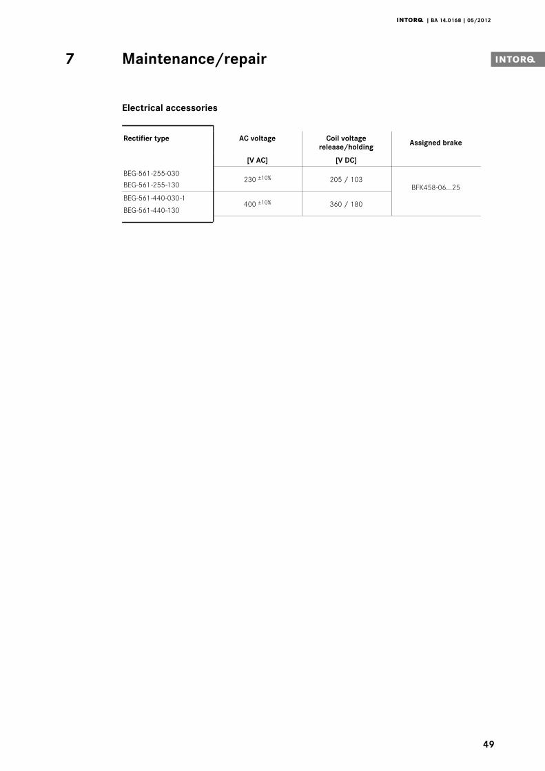
Electrical accessories
Rectifier type AC voltage Coil voltagerelease/holding Assigned brake
[V AC] [V DC]
BEG-561-255-030230 ±10% 205 / 103
BFK458-06...25BEG-561-255-130
BEG-561-440-030-1400 ±10% 360 / 180
BEG-561-440-130
Troubleshooting and fault elimination8
j | BA 14.0168 | 05/2012
50
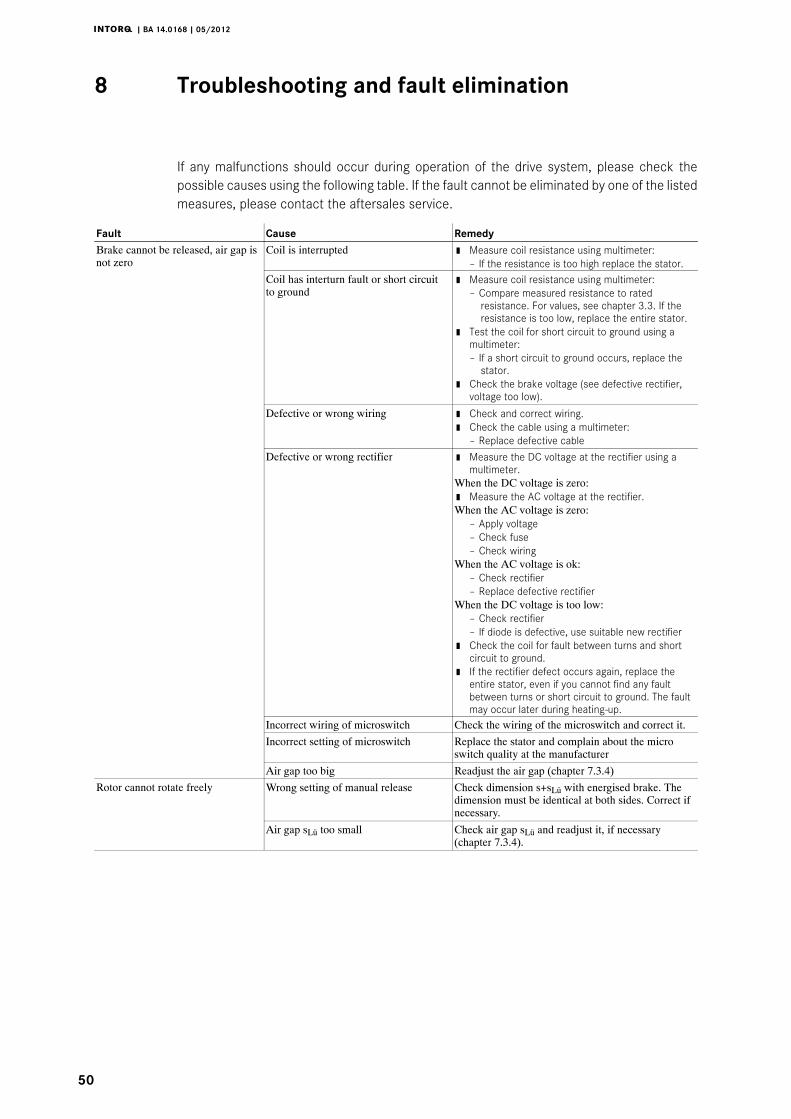
8 Troubleshooting and fault elimination
If any malfunctions should occur during operation of the drive system, please check thepossible causes using the following table. If the fault cannot be eliminated by one of the listedmeasures, please contact the aftersales service.
Fault Cause RemedyBrake cannot be released, air gap isnot zero
Coil is interrupted | Measure coil resistance using multimeter:– If the resistance is too high replace the stator.
Coil has interturn fault or short circuitto ground
| Measure coil resistance using multimeter:– Compare measured resistance to rated
resistance. For values, see chapter 3.3. If theresistance is too low, replace the entire stator.
| Test the coil for short circuit to ground using amultimeter:– If a short circuit to ground occurs, replace the
stator.| Check the brake voltage (see defective rectifier,
voltage too low).
Defective or wrong wiring | Check and correct wiring.| Check the cable using a multimeter:
– Replace defective cable
Defective or wrong rectifier | Measure the DC voltage at the rectifier using amultimeter.
When the DC voltage is zero:| Measure the AC voltage at the rectifier.When the AC voltage is zero:
– Apply voltage– Check fuse– Check wiring
When the AC voltage is ok:– Check rectifier– Replace defective rectifier
When the DC voltage is too low:– Check rectifier– If diode is defective, use suitable new rectifier
| Check the coil for fault between turns and shortcircuit to ground.
| If the rectifier defect occurs again, replace theentire stator, even if you cannot find any faultbetween turns or short circuit to ground. The faultmay occur later during heating-up.
Incorrect wiring of microswitch Check the wiring of the microswitch and correct it.Incorrect setting of microswitch Replace the stator and complain about the micro
switch quality at the manufacturer
Air gap too big Readjust the air gap (chapter 7.3.4)Rotor cannot rotate freely Wrong setting of manual release Check dimension s+sLü with energised brake. The
dimension must be identical at both sides. Correct ifnecessary.
Air gap sLü too small Check air gap sLü and readjust it, if necessary(chapter 7.3.4).
Troubleshooting and fault elimination8 i
j | BA 14.0168 | 05/2012
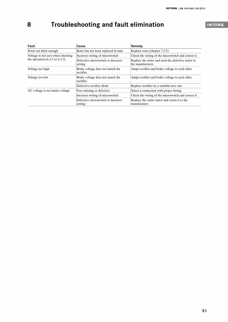
51
RemedyCauseFaultRotor not thick enough Rotor has not been replaced in time Replace rotor (chapter 7.3.5)Voltage is not zero when checkingthe operation (6.2.2 or 6.2.3)
Incorrect wiring of microswitch Check the wiring of the microswitch and correct it.Defective microswitch or incorrectsetting
Replace the stator and send the defective stator tothe manufacturer.
Voltage too high Brake voltage does not match therectifier
Adapt rectifier and brake voltage to each other.
Voltage too low Brake voltage does not match therectifier
Adapt rectifier and brake voltage to each other.
Defective rectifier diode Replace rectifier by a suitable new one.AC voltage is not mains voltage Fuse missing or defective Select a connection with proper fusing.
Incorrect wiring of microswitch Check the wiring of the microswitch and correct it.Defective microswitch or incorrectsetting
Replace the entire stator and return it to themanufacturer.
INTORQ GmbH & Co KGGermanyPostfach 1103D-31849 AerzenWülmser Weg 5D-31855 Aerzen+49 5154 70534-444+49 5154 [email protected]
INTORQ (SHANGHAI) Co., LtdChinaNo. 600, Xin Yuan RoadBuilding No. 6 / Zone BNan Hui District, LingangShanghai, China 201306应拓柯制动器(上海)有限公司中国新元南路600号6号楼1楼B座上海 南汇 201306
+86 21 20363-810+86 21 [email protected]
INTORQ US Inc.USA300 Lake Ridge Drive SESmyrna, GA 30082+1 678 309-1155+1 678 [email protected]
1334
3893
|BA
14.0
168
|EN
|4.
1|
©05
.201
2|
TD09
|10
98
76
54
32
1
www.intorq.com


![BFK458 spring-applied brake - Lenze Selection · 2020. 12. 14. · 6I7 INTORQ I BFK458 spring-applied brake A powerful and complete range 9 sizes Standard voltages [V DC] 24, 96,](https://img.pdfslide.net/doc/110x75/6145f4848f9ff812541ff53e/bfk458-spring-applied-brake-lenze-selection-2020-12-14-6i7-intorq-i-bfk458.jpg)


![INTORQ BFK458 Spring-applied brake · 2015. 7. 22. · 1 [s] Engagement time, t 1 = t 11 + t 12 t 2 [s] Disengagement time (time from the beginning of the torque reduction until 0.1](https://img.pdfslide.net/doc/110x75/60ec2a6a0c631d665a65ea6b/intorq-bfk458-spring-applied-brake-2015-7-22-1-s-engagement-time-t-1-t.jpg)