Embed Size (px)
Citation preview
Suggested Tools
• 3/8 Drive Sockets: 8,10,12,14,17,& 19 mm• 3/8 Ratchet• Combination Wrenches: 8,9,10,12,14,17,& 19 mm• 3/8 Drive Allen Socket: 6 mm• Engine Crane• Engine Strap or Chain• 1-2X4X12” Board• Pick Tool: Hook Type• 1.6 Liter Suzuki Engine (Not Included)• Slip Joint Pliers• Phillips Screwdriver• 1/2” Drill Bit (Supplied with Kit)• Electric Hand Drill• Bench Vice• Hack Saw• Torque Wrench
CAUTION: Safety glasses should be worn at all times when working with vehicles and related tools and equipment.
86-95 Suzuki Samurai 1.6L Engine Swap Adapter Kit(SKU# SEU-16SK)! Instructions also apply to: SKU # SEU-16SKHDMM
Installation Instructions
For additional copies of these and other instructions go to:www.lowrangeoffroad and click on the “Tech and Instructions” tab.
Engine Not Included
Order SKU# SEU-16SKHDMM for the 1.6L Engine Swap Kit that includes 2 Heavy Duty Motor Mounts.
SKU# SEU-16SK
Revised 7/29/14
Instructions Created by an:
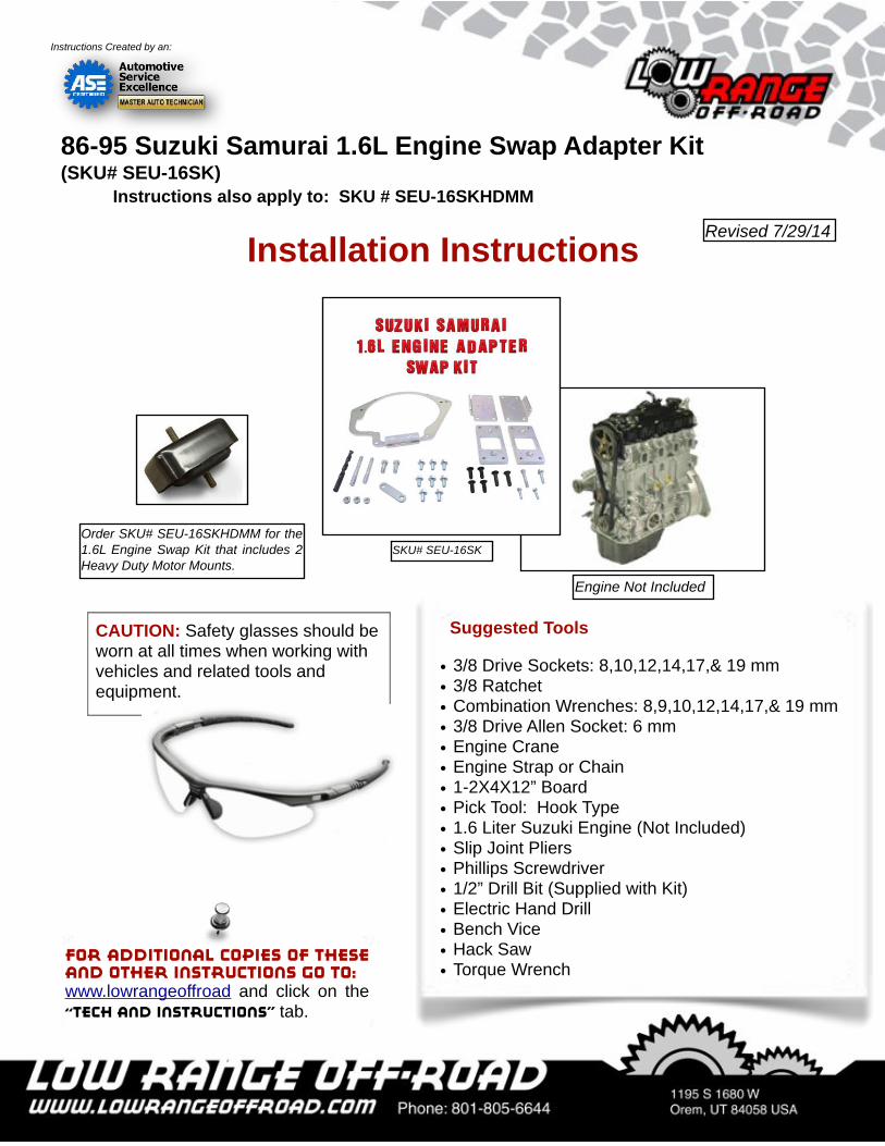
Step 1Lift and support the vehicle on a twin post lift.
Note: We used a twin post lift, but this job could easily be done with a floor jack and (2) safety stands.
Tech TipProper positioning of floor jack.
Tech TipProper positioning of safety stands.
Instruction Limitations & CautionsThese instructions do NOT show the removal of the 1.6L engine. The one we are installing was removed previously.
These instructions include removing the 1.3L engine from the Samurai and installing the 1.6L engine in its place. We show most the mechan ica l connections, such as the motor mounts and the engine-to-transmission adapter, but we do not show how to connect the cooling system, fuel system, engine computer, wiring harness and exhaust system. The installation of these components will be left up the the customer.
Please be aware that the 1.6L engine sits a little taller than the 1.3 which means the hood, when closed, may hit t h e a l u m i n u m a i r i n t a k e t u b e . Consequently, the air intake or the hood will likely need to be modified after this installation.
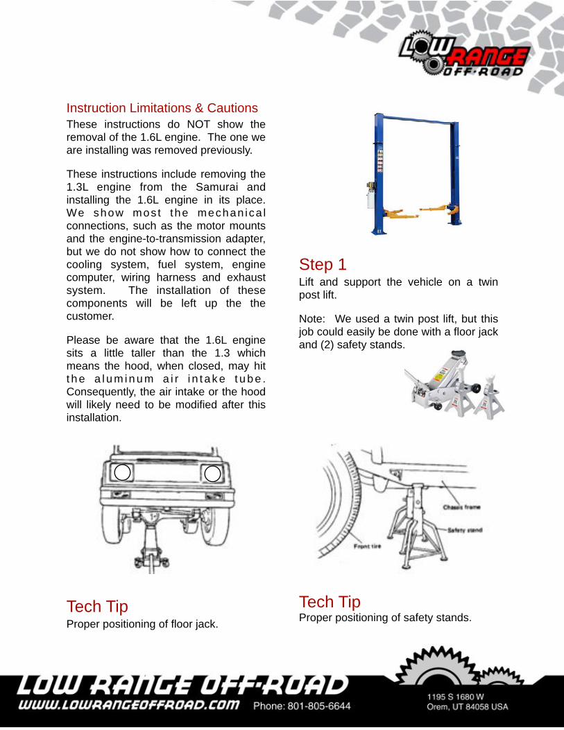
Step 2Drain the engine oil by placing a drain container under the oil pan and removing the drain plug using a 14 mm socket.
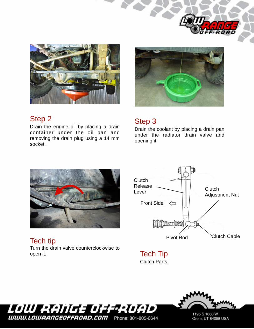
Step 3Drain the coolant by placing a drain pan under the radiator drain valve and opening it.
Tech tipTurn the drain valve counterclockwise to open it. Tech Tip
Clutch Parts.
Clutch Adjustment Nut
Clutch Release Lever
Clutch CablePivot Rod
Front Side
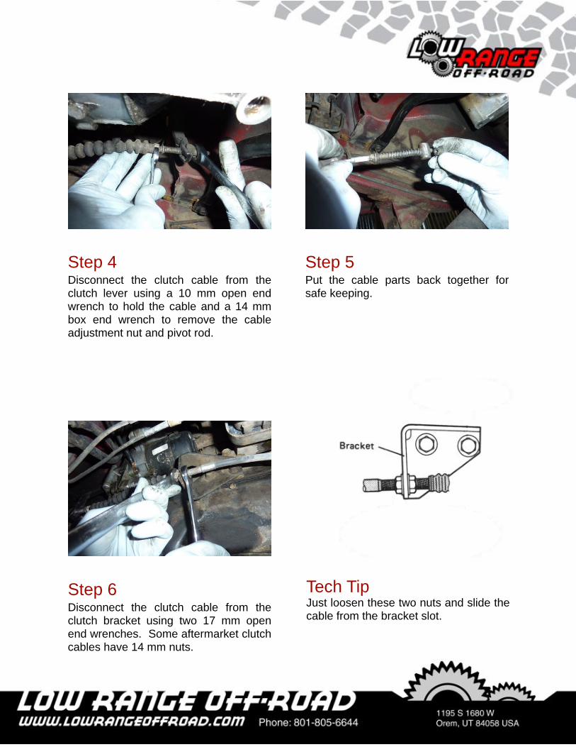
Step 5Put the cable parts back together for safe keeping.
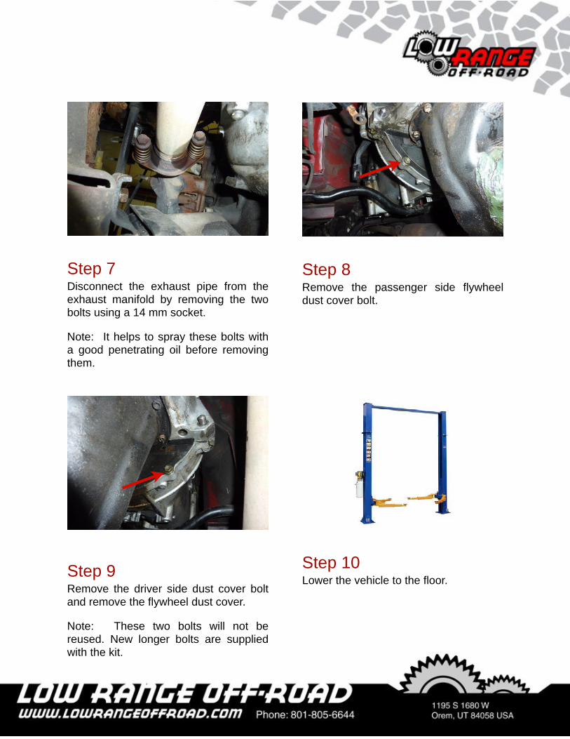
Step 6Disconnect the clutch cable from the clutch bracket using two 17 mm open end wrenches. Some aftermarket clutch cables have 14 mm nuts.
Tech TipJust loosen these two nuts and slide the cable from the bracket slot.
Step 4Disconnect the clutch cable from the clutch lever using a 10 mm open end wrench to hold the cable and a 14 mm box end wrench to remove the cable adjustment nut and pivot rod.
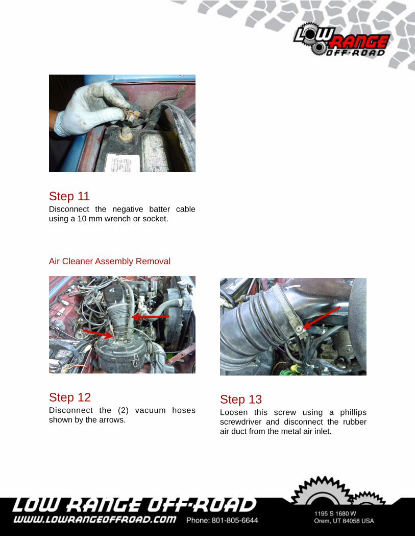
Step 7Disconnect the exhaust pipe from the exhaust manifold by removing the two bolts using a 14 mm socket.
Note: It helps to spray these bolts with a good penetrating oil before removing them.
Step 8Remove the passenger side flywheel dust cover bolt.
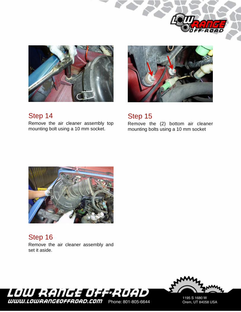
Step 9Remove the driver side dust cover bolt and remove the flywheel dust cover.
Note: These two bolts will not be reused. New longer bolts are supplied with the kit.
Step 10Lower the vehicle to the floor.
Step 11Disconnect the negative batter cable using a 10 mm wrench or socket.
Step 12Disconnect the (2) vacuum hoses shown by the arrows.
Air Cleaner Assembly Removal
Step 13Loosen this screw using a phillips screwdriver and disconnect the rubber air duct from the metal air inlet.
Step 14Remove the air cleaner assembly top mounting bolt using a 10 mm socket.
Step 15Remove the (2) bottom air cleaner mounting bolts using a 10 mm socket
Step 16Remove the air cleaner assembly and set it aside.
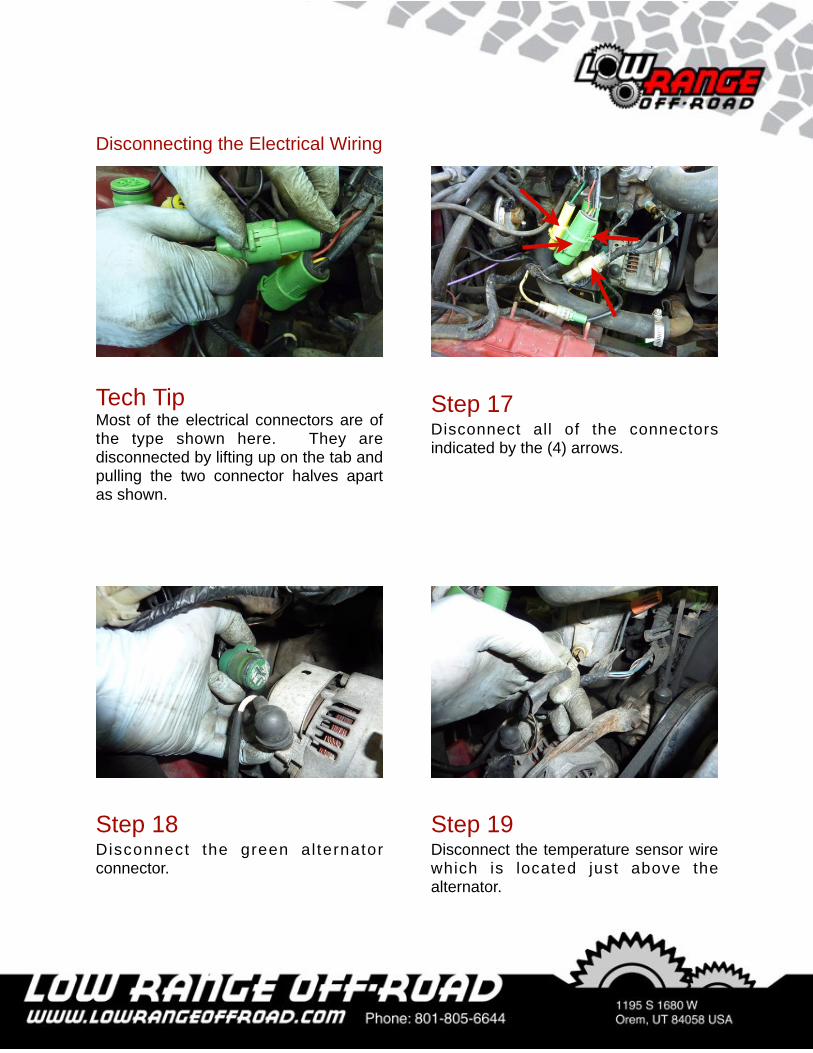
Step 17Disconnect all of the connectors indicated by the (4) arrows.
Tech TipMost of the electrical connectors are of the type shown here. They are disconnected by lifting up on the tab and pulling the two connector halves apart as shown.
Disconnecting the Electrical Wiring
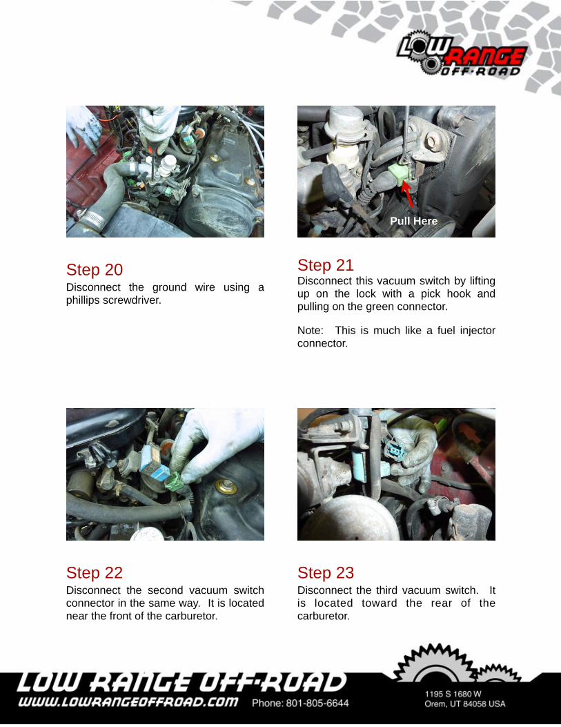
Step 19Disconnect the temperature sensor wire which is located just above the alternator.
Step 18Disconnect the green al ternator connector.
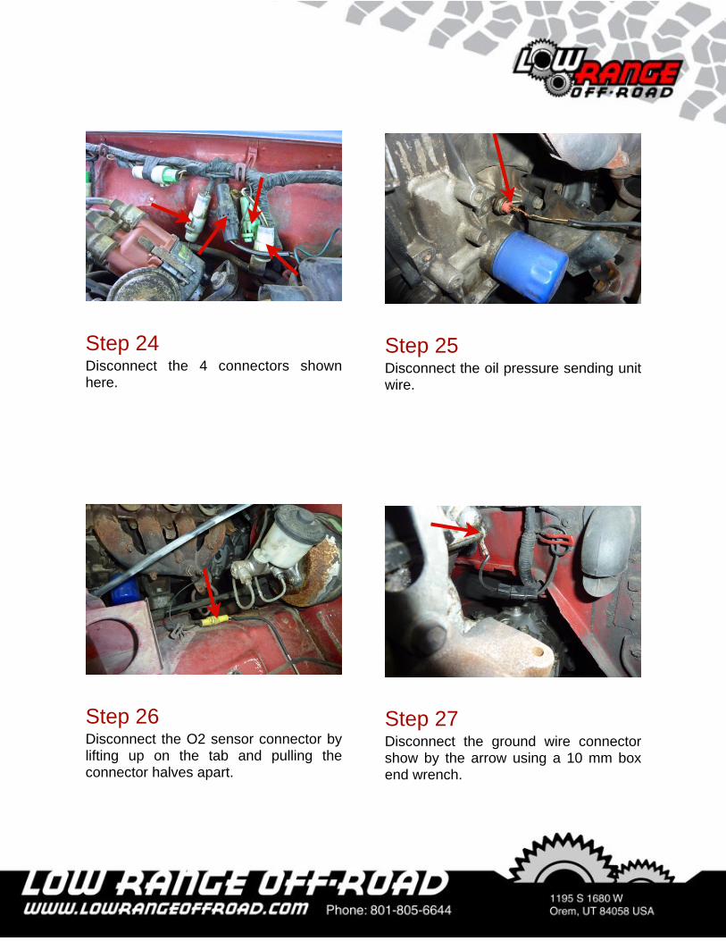
Step 20Disconnect the ground wire using a phillips screwdriver.
Step 21Disconnect this vacuum switch by lifting up on the lock with a pick hook and pulling on the green connector.
Note: This is much like a fuel injector connector.
Step 23Disconnect the third vacuum switch. It is located toward the rear of the carburetor.
Step 22Disconnect the second vacuum switch connector in the same way. It is located near the front of the carburetor.
Pull Here
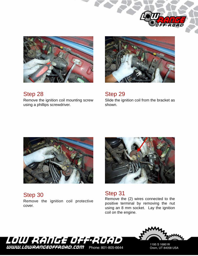
Step 24Disconnect the 4 connectors shown here.
Step 25Disconnect the oil pressure sending unit wire.
Step 26Disconnect the O2 sensor connector by lifting up on the tab and pulling the connector halves apart.
Step 27Disconnect the ground wire connector show by the arrow using a 10 mm box end wrench.
Step 29Slide the ignition coil from the bracket as shown.
Step 28Remove the ignition coil mounting screw using a phillips screwdriver.
Step 30Remove the ignition coil protective cover.
Step 31Remove the (2) wires connected to the positive terminal by removing the nut using an 8 mm socket. Lay the ignition coil on the engine.
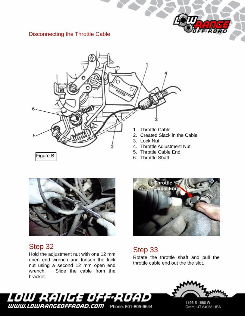
Step 32Hold the adjustment nut with one 12 mm open end wrench and loosen the lock nut using a second 12 mm open end wrench. Slide the cable from the bracket.
Disconnecting the Throttle Cable
1. Throttle Cable2. Created Slack in the Cable3. Lock Nut4. Throttle Adjustment Nut5. Throttle Cable End6. Throttle Shaft
5
Figure B
6
Step 33Rotate the throttle shaft and pull the throttle cable end out the the slot.
Throttle Cable End
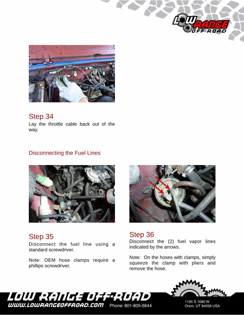
Step 34Lay the throttle cable back out of the way.
Step 35Disconnect the fuel line using a standard screwdriver.
Note: OEM hose clamps require a phillips screwdriver.
Step 36Disconnect the (2) fuel vapor lines indicated by the arrows.
Note: On the hoses with clamps, simply squeeze the clamp with pliers and remove the hose.
Disconnecting the Fuel Lines
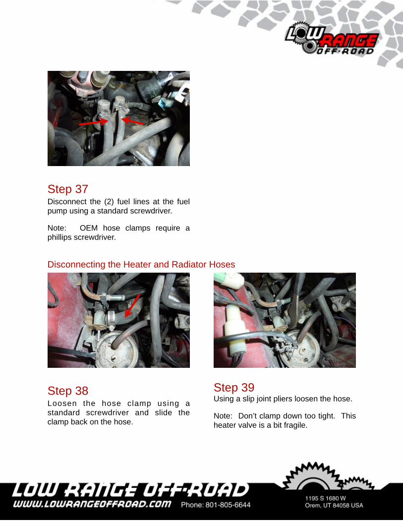
Step 37Disconnect the (2) fuel lines at the fuel pump using a standard screwdriver.
Note: OEM hose clamps require a phillips screwdriver.
Step 38Loosen the hose clamp using a standard screwdriver and slide the clamp back on the hose.
Step 39Using a slip joint pliers loosen the hose.
Note: Don’t clamp down too tight. This heater valve is a bit fragile.
Disconnecting the Heater and Radiator Hoses
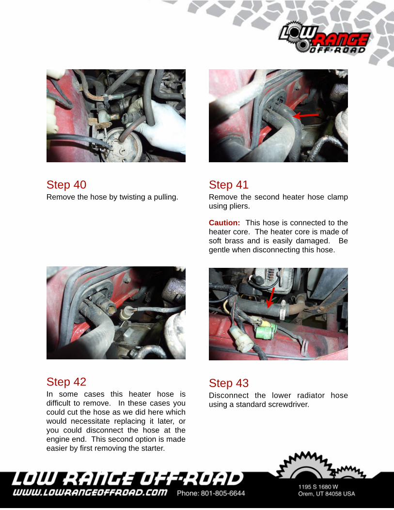
Step 41Remove the second heater hose clamp using pliers.
Caution: This hose is connected to the heater core. The heater core is made of soft brass and is easily damaged. Be gentle when disconnecting this hose.
Step 40Remove the hose by twisting a pulling.
Step 42In some cases this heater hose is difficult to remove. In these cases you could cut the hose as we did here which would necessitate replacing it later, or you could disconnect the hose at the engine end. This second option is made easier by first removing the starter.
Step 43Disconnect the lower radiator hose using a standard screwdriver.
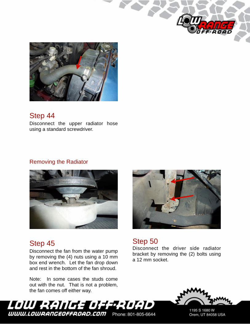
Step 44Disconnect the upper radiator hose using a standard screwdriver.
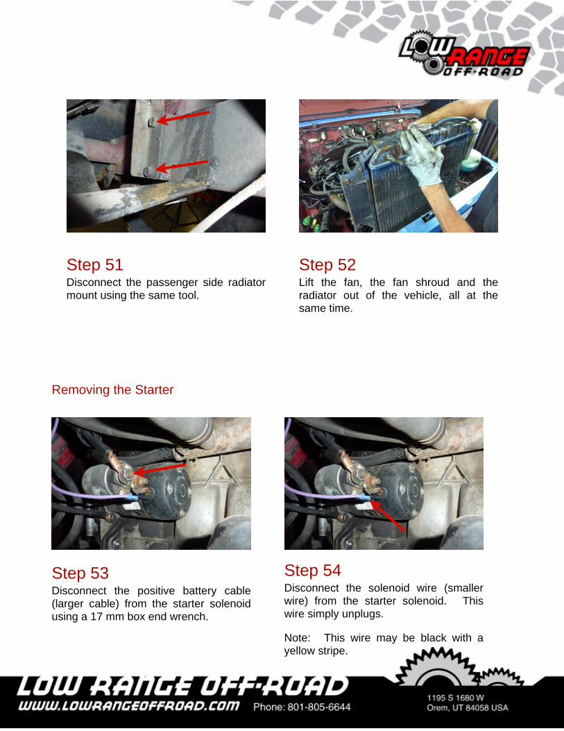
Step 45Disconnect the fan from the water pump by removing the (4) nuts using a 10 mm box end wrench. Let the fan drop down and rest in the bottom of the fan shroud.
Note: In some cases the studs come out with the nut. That is not a problem, the fan comes off either way.
Step 50Disconnect the driver side radiator bracket by removing the (2) bolts using a 12 mm socket.
Removing the Radiator
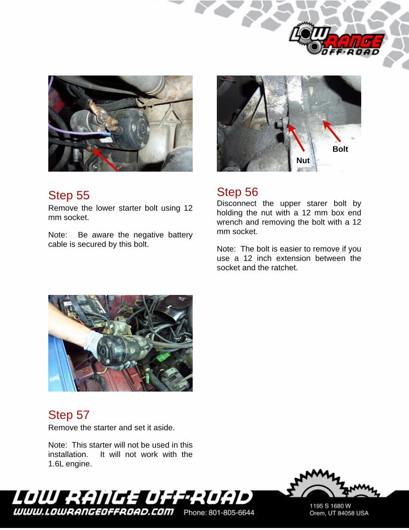
Step 52Lift the fan, the fan shroud and the radiator out of the vehicle, all at the same time.
Step 51Disconnect the passenger side radiator mount using the same tool.
Step 54Disconnect the solenoid wire (smaller wire) from the starter solenoid. This wire simply unplugs.
Note: This wire may be black with a yellow stripe.
Step 53Disconnect the positive battery cable (larger cable) from the starter solenoid using a 17 mm box end wrench.
Removing the Starter
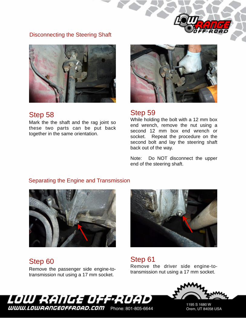
Step 55Remove the lower starter bolt using 12 mm socket.
Note: Be aware the negative battery cable is secured by this bolt.
Step 56Disconnect the upper starer bolt by holding the nut with a 12 mm box end wrench and removing the bolt with a 12 mm socket.
Note: The bolt is easier to remove if you use a 12 inch extension between the socket and the ratchet.
NutBolt
Step 57Remove the starter and set it aside.
Note: This starter will not be used in this installation. It will not work with the 1.6L engine.
Step 58Mark the the shaft and the rag joint so these two parts can be put back together in the same orientation.
Step 59While holding the bolt with a 12 mm box end wrench, remove the nut using a second 12 mm box end wrench or socket. Repeat the procedure on the second bolt and lay the steering shaft back out of the way.
Note: Do NOT disconnect the upper end of the steering shaft.
Disconnecting the Steering Shaft
Step 60Remove the passenger side engine-to- transmission nut using a 17 mm socket.
Step 61Remove the driver side engine-to- transmission nut using a 17 mm socket.
Separating the Engine and Transmission
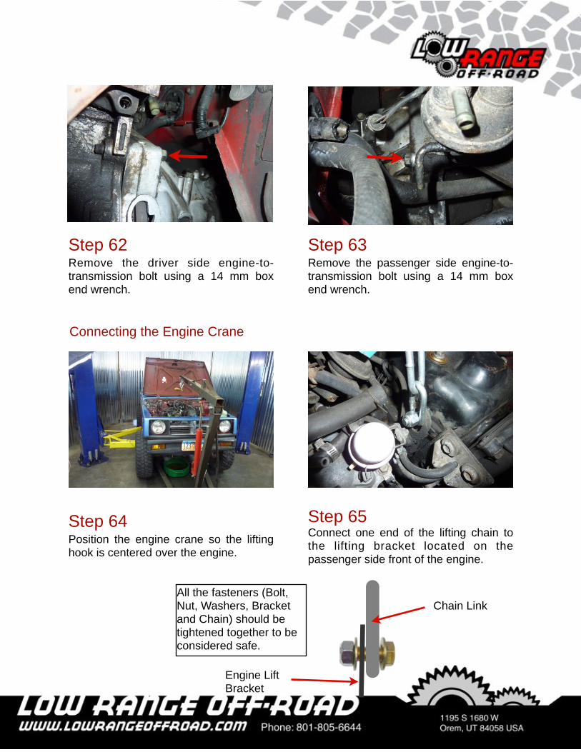
Step 63Remove the passenger side engine-to- transmission bolt using a 14 mm box end wrench.
Step 62Remove the driver side engine-to- transmission bolt using a 14 mm box end wrench.
Step 64Position the engine crane so the lifting hook is centered over the engine.
Step 65Connect one end of the lifting chain to the lifting bracket located on the passenger side front of the engine.
Connecting the Engine Crane
Chain Link
Engine Lift Bracket
All the fasteners (Bolt, Nut, Washers, Bracket and Chain) should be tightened together to be considered safe.
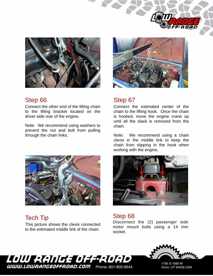
Step 67Connect the estimated center of the chain to the lifting hook. Once the chain is hooked, move the engine crane up until all the slack is removed from the chain.
Note: We recommend using a chain clevis in the middle link to keep the chain from slipping in the hook when working with the engine.
Step 66Connect the other end of the lifting chain to the lifting bracket located on the driver side rear of the engine.
Note: We recommend using washers to prevent the nut and bolt from pulling through the chain links.
Tech TipThis picture shows the clevis connected to the estimated middle link of the chain.
Step 68Disconnect the (2) passenger side motor mount bolts using a 14 mm socket.
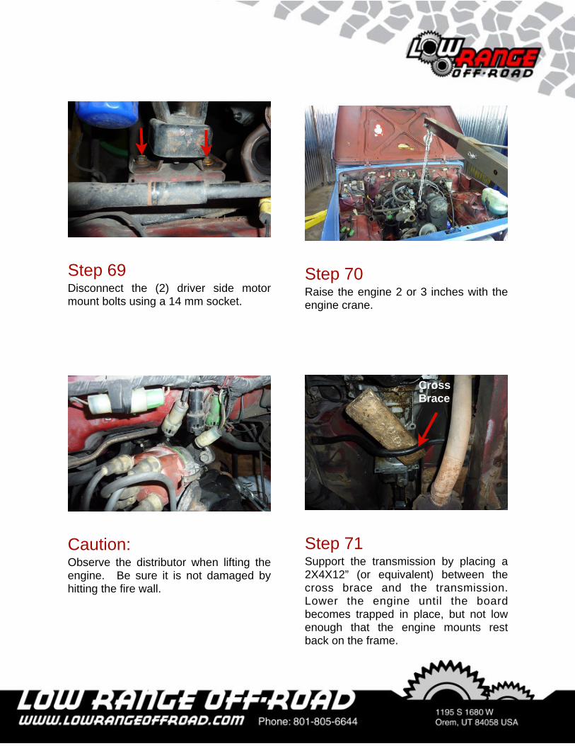
Step 69Disconnect the (2) driver side motor mount bolts using a 14 mm socket.
Step 70Raise the engine 2 or 3 inches with the engine crane.
Caution:Observe the distributor when lifting the engine. Be sure it is not damaged by hitting the fire wall.
Step 71Support the transmission by placing a 2X4X12” (or equivalent) between the cross brace and the transmission. Lower the engine until the board becomes trapped in place, but not low enough that the engine mounts rest back on the frame.
Cross Brace
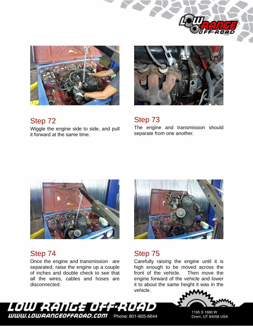
Step 72Wiggle the engine side to side, and pull it forward at the same time.
Step 73The engine and transmission should separate from one another.
Step 74Once the engine and transmission are separated, raise the engine up a couple of inches and double check to see that all the wires, cables and hoses are disconnected.
Step 75Carefully raising the engine until it is high enough to be moved across the front of the vehicle. Then move the engine forward of the vehicle and lower it to about the same height it was in the vehicle.
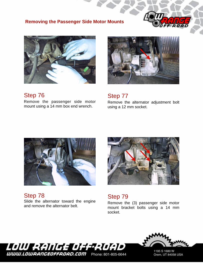
Step 79Remove the (3) passenger side motor mount bracket bolts using a 14 mm socket.
Step 76Remove the passenger side motor mount using a 14 mm box end wrench.
Step 77Remove the alternator adjustment bolt using a 12 mm socket.
Step 78Slide the alternator toward the engine and remove the alternator belt.
Removing the Passenger Side Motor Mounts
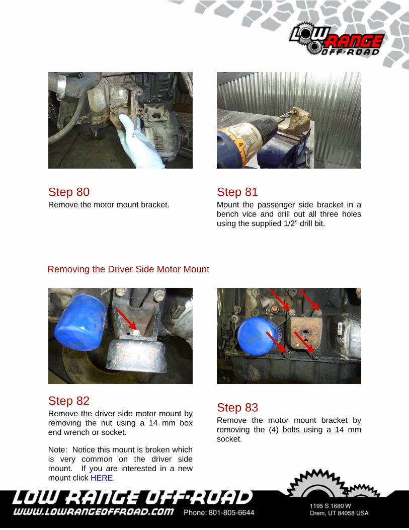
Step 81Mount the passenger side bracket in a bench vice and drill out all three holes using the supplied 1/2” drill bit.
Step 80Remove the motor mount bracket.
Step 83Remove the motor mount bracket by removing the (4) bolts using a 14 mm socket.
Step 82Remove the driver side motor mount by removing the nut using a 14 mm box end wrench or socket.
Note: Notice this mount is broken which is very common on the driver side mount. If you are interested in a new mount click HERE.
Removing the Driver Side Motor Mount
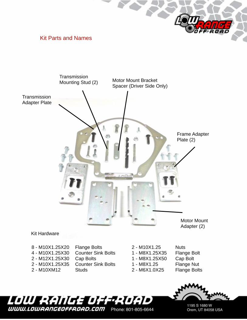
Transmission Adapter Plate
Frame Adapter Plate (2)
Motor Mount Adapter (2)
Transmission Mounting Stud (2) Motor Mount Bracket
Spacer (Driver Side Only)
Kit Parts and Names
8 - M10X1.25X20 ! Flange Bolts4 - M10X1.25X30 ! Counter Sink Bolts2 - M12X1.25X30 ! Cap Bolts2 - M10X1.25X35 ! Counter Sink Bolts2 - M10XM12 ! Studs
2 - M10X1.25 ! Nuts1 - M8X1.25X35 ! Flange Bolt1 - M8X1.25X50 ! Cap Bolt1 - M8X1.25 !! Flange Nut2 - M6X1.0X25 ! Flange Bolts
Kit Hardware
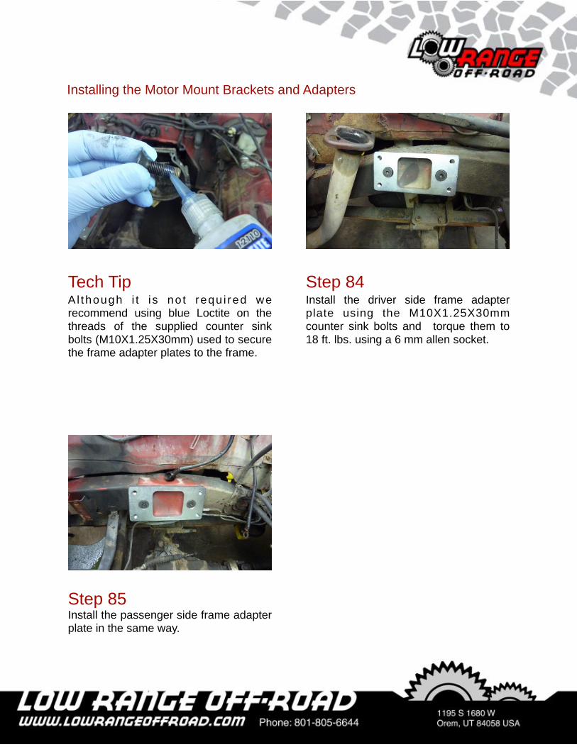
Step 84Install the driver side frame adapter plate using the M10X1.25X30mm counter sink bolts and torque them to 18 ft. lbs. using a 6 mm allen socket.
Installing the Motor Mount Brackets and Adapters
Tech TipAl though i t i s no t requ i red we recommend using blue Loctite on the threads of the supplied counter sink bolts (M10X1.25X30mm) used to secure the frame adapter plates to the frame.
Step 85Install the passenger side frame adapter plate in the same way.
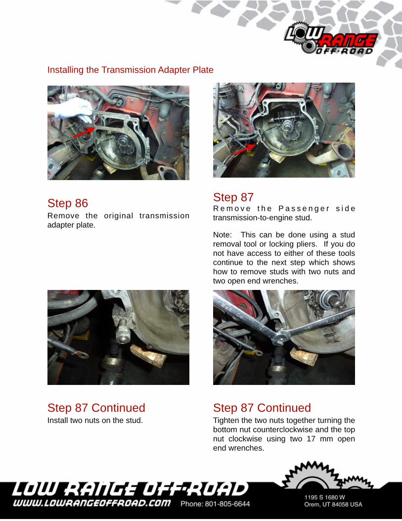
Step 86Remove the original transmission adapter plate.
Step 87R e m o v e t h e P a s s e n g e r s i d e transmission-to-engine stud.
Note: This can be done using a stud removal tool or locking pliers. If you do not have access to either of these tools continue to the next step which shows how to remove studs with two nuts and two open end wrenches.
Installing the Transmission Adapter Plate
Step 87 ContinuedTighten the two nuts together turning the bottom nut counterclockwise and the top nut clockwise using two 17 mm open end wrenches.
Step 87 ContinuedInstall two nuts on the stud.
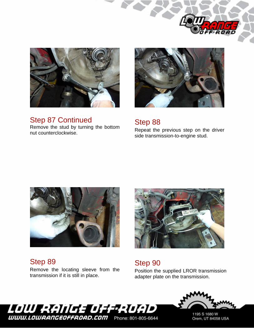
Step 88Repeat the previous step on the driver side transmission-to-engine stud.
Step 87 ContinuedRemove the stud by turning the bottom nut counterclockwise.
Step 89Remove the locating sleeve from the transmission if it is still in place.
Step 90Position the supplied LROR transmission adapter plate on the transmission.
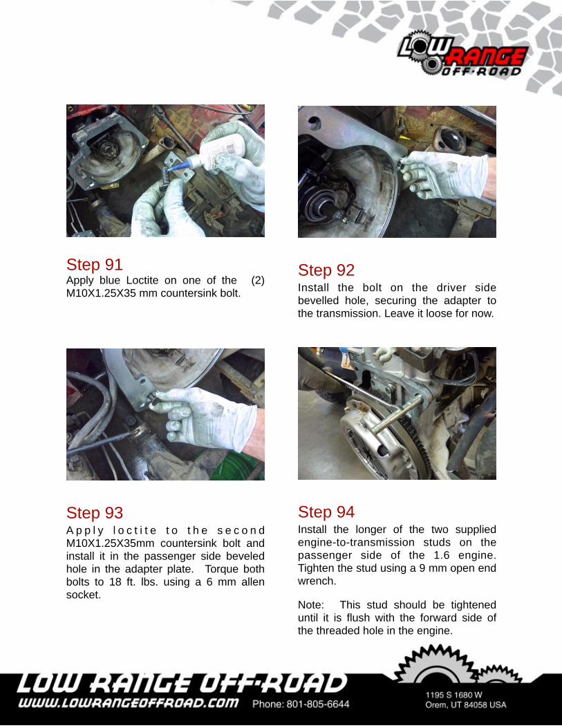
Step 91Apply blue Loctite on one of the (2) M10X1.25X35 mm countersink bolt.
Step 92Install the bolt on the driver side bevelled hole, securing the adapter to the transmission. Leave it loose for now.
Step 93A p p l y l o c t i t e t o t h e s e c o n d M10X1.25X35mm countersink bolt and install it in the passenger side beveled hole in the adapter plate. Torque both bolts to 18 ft. lbs. using a 6 mm allen socket.
Step 94Install the longer of the two supplied engine-to-transmission studs on the passenger side of the 1.6 engine. Tighten the stud using a 9 mm open end wrench.
Note: This stud should be tightened until it is flush with the forward side of the threaded hole in the engine.
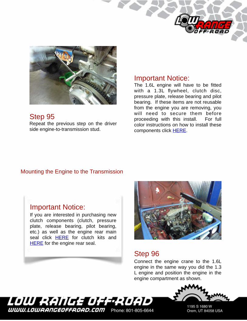
Step 95Repeat the previous step on the driver side engine-to-transmission stud.
Step 96Connect the engine crane to the 1.6L engine in the same way you did the 1.3 L engine and position the engine in the engine compartment as shown.
Mounting the Engine to the Transmission
Important Notice:If you are interested in purchasing new clutch components (clutch, pressure plate, release bearing, pilot bearing, etc.) as well as the engine rear main seal click HERE for clutch kits and HERE for the engine rear seal.
Important Notice:The 1.6L engine will have to be fitted with a 1.3L flywheel, clutch disc, pressure plate, release bearing and pilot bearing. If these items are not reusable from the engine you are removing, you will need to secure them before proceeding with this install. For full color instructions on how to install these components click HERE.
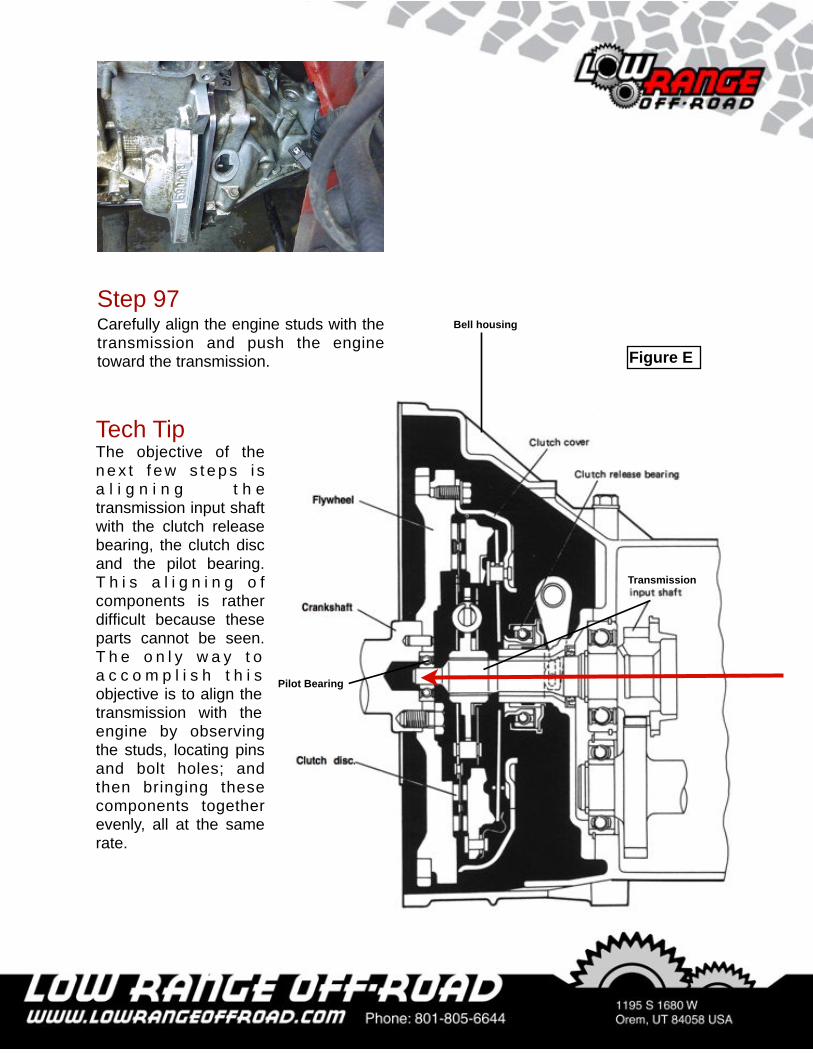
Transmission
Bell housing
Figure E
Tech TipThe objective of the n e x t f e w s t e p s i s a l i g n i n g t h e transmission input shaft with the clutch release bearing, the clutch disc and the pilot bearing. T h i s a l i g n i n g o f components is rather difficult because these parts cannot be seen. T h e o n l y w a y t o a c c o m p l i s h t h i s objective is to align the transmission with the engine by observing the studs, locating pins and bolt holes; and then bringing these components together evenly, all at the same rate.
Pilot Bearing
Step 97Carefully align the engine studs with the transmission and push the engine toward the transmission.
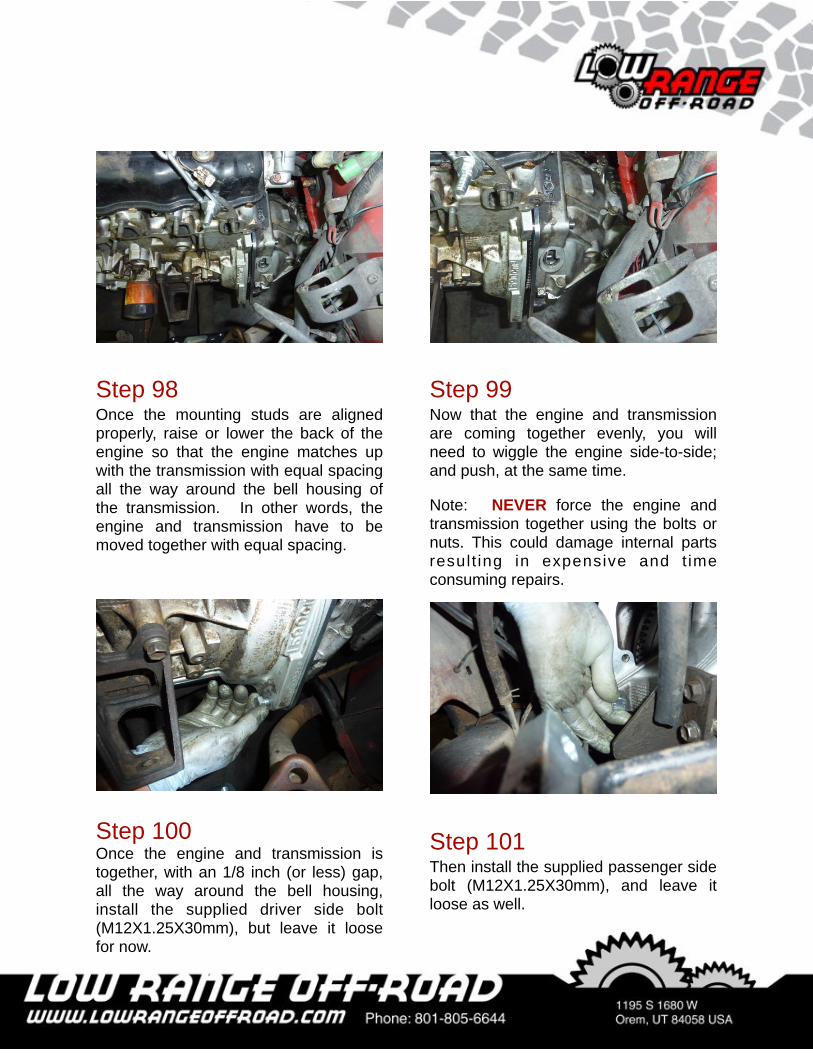
Step 98Once the mounting studs are aligned properly, raise or lower the back of the engine so that the engine matches up with the transmission with equal spacing all the way around the bell housing of the transmission. In other words, the engine and transmission have to be moved together with equal spacing.
Step 99Now that the engine and transmission are coming together evenly, you will need to wiggle the engine side-to-side; and push, at the same time.
Note: NEVER force the engine and transmission together using the bolts or nuts. This could damage internal parts result ing in expensive and t ime consuming repairs.
Step 100Once the engine and transmission is together, with an 1/8 inch (or less) gap, all the way around the bell housing, install the supplied driver side bolt (M12X1.25X30mm), but leave it loose for now.
Step 101Then install the supplied passenger side bolt (M12X1.25X30mm), and leave it loose as well.
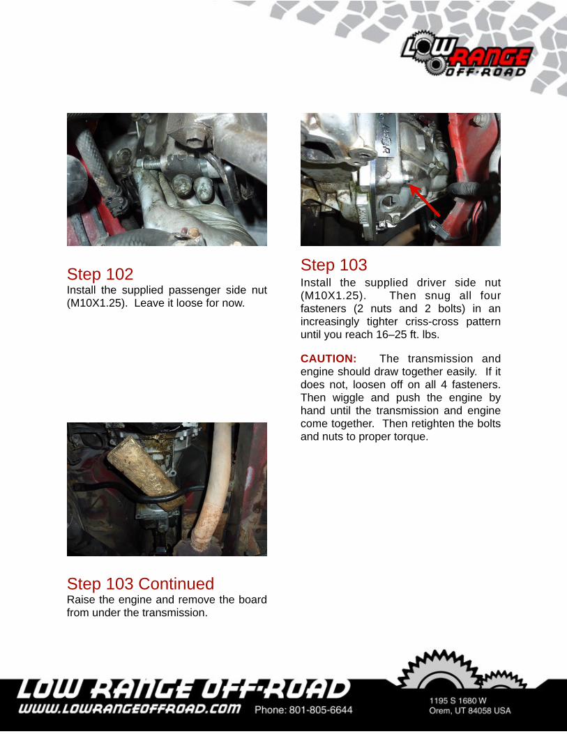
Step 102Install the supplied passenger side nut (M10X1.25). Leave it loose for now.
Step 103Install the supplied driver side nut (M10X1.25). Then snug all four fasteners (2 nuts and 2 bolts) in an increasingly tighter criss-cross pattern until you reach 16–25 ft. lbs.
CAUTION: The transmission and engine should draw together easily. If it does not, loosen off on all 4 fasteners. Then wiggle and push the engine by hand until the transmission and engine come together. Then retighten the bolts and nuts to proper torque.
Step 103 ContinuedRaise the engine and remove the board from under the transmission.
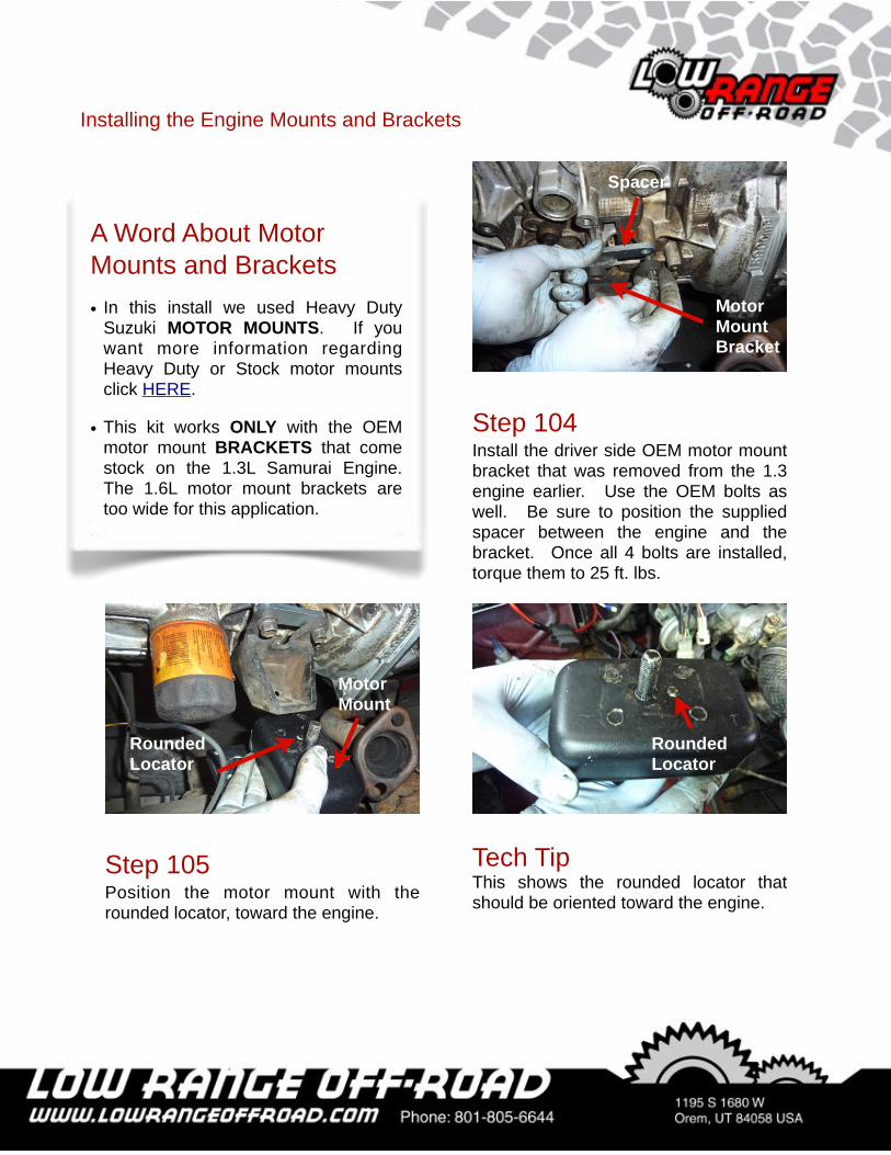
Step 104Install the driver side OEM motor mount bracket that was removed from the 1.3 engine earlier. Use the OEM bolts as well. Be sure to position the supplied spacer between the engine and the bracket. Once all 4 bolts are installed, torque them to 25 ft. lbs.
Step 105Position the motor mount with the rounded locator, toward the engine.
Tech TipThis shows the rounded locator that should be oriented toward the engine.
Rounded Locator
Rounded Locator
Installing the Engine Mounts and Brackets
A Word About Motor Mounts and Brackets• In this install we used Heavy Duty
Suzuki MOTOR MOUNTS. If you want more information regarding Heavy Duty or Stock motor mounts click HERE.
• This kit works ONLY with the OEM motor mount BRACKETS that come stock on the 1.3L Samurai Engine. The 1.6L motor mount brackets are too wide for this application.
Spacer
Motor Mount Bracket
Motor Mount
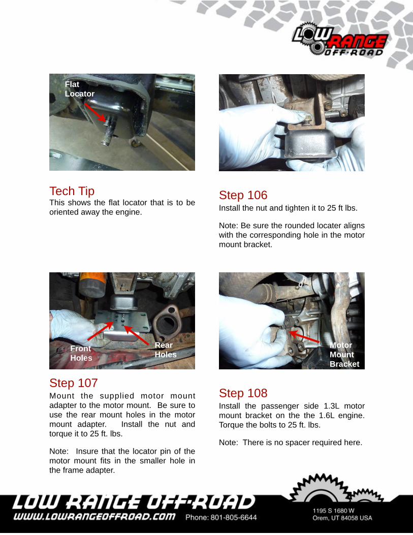
Tech TipThis shows the flat locator that is to be oriented away the engine.
Flat Locator
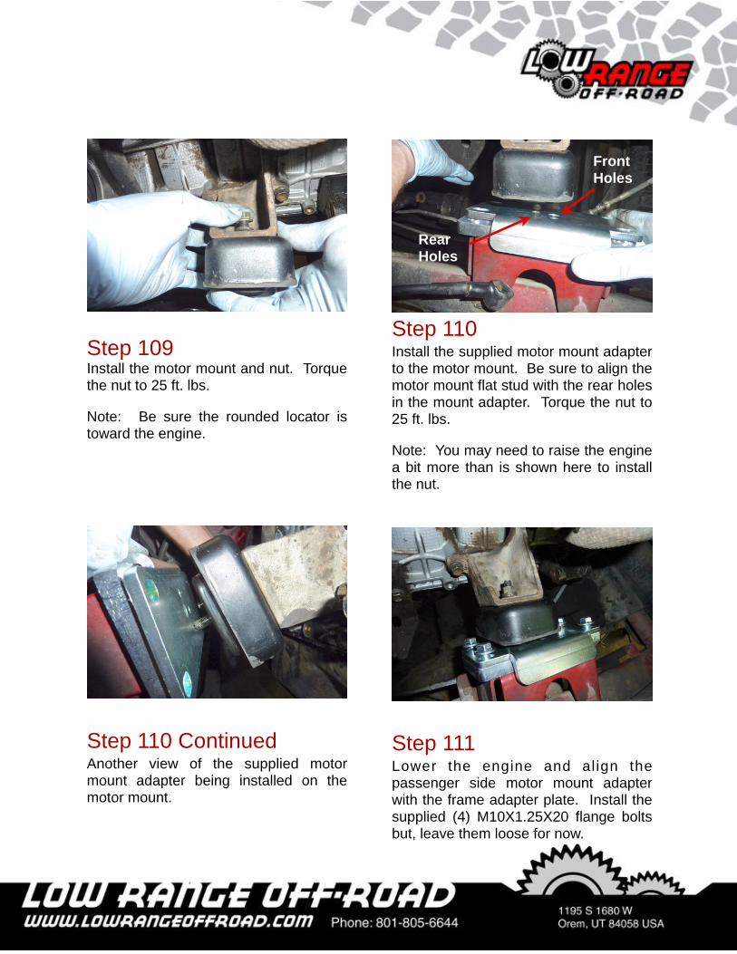
Step 106Install the nut and tighten it to 25 ft lbs.
Note: Be sure the rounded locater aligns with the corresponding hole in the motor mount bracket.
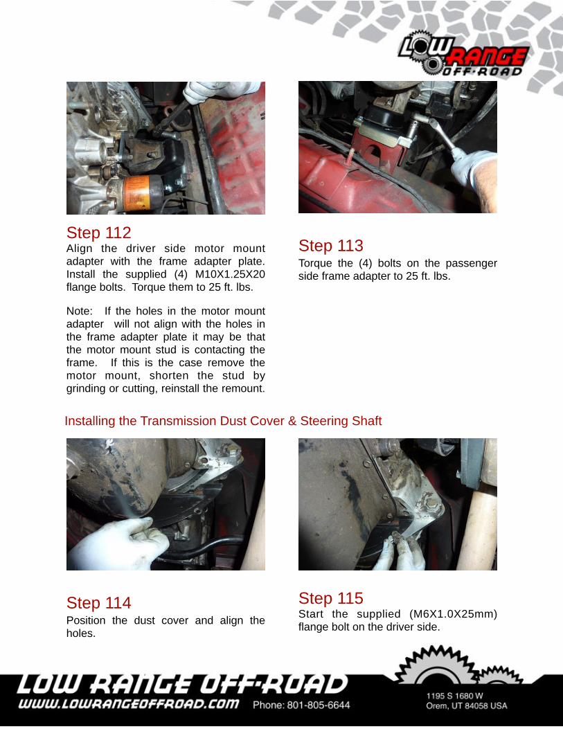
Step 107Mount the supplied motor mount adapter to the motor mount. Be sure to use the rear mount holes in the motor mount adapter. Install the nut and torque it to 25 ft. lbs.
Note: Insure that the locator pin of the motor mount fits in the smaller hole in the frame adapter.
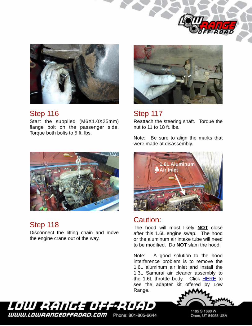
Step 108Install the passenger side 1.3L motor mount bracket on the the 1.6L engine. Torque the bolts to 25 ft. lbs.
Note: There is no spacer required here.
Motor Mount Bracket
Rear Holes
Front Holes
Step 109Install the motor mount and nut. Torque the nut to 25 ft. lbs.
Note: Be sure the rounded locator is toward the engine.
Step 110Install the supplied motor mount adapter to the motor mount. Be sure to align the motor mount flat stud with the rear holes in the mount adapter. Torque the nut to 25 ft. lbs.
Note: You may need to raise the engine a bit more than is shown here to install the nut.
Step 110 ContinuedAnother view of the supplied motor mount adapter being installed on the motor mount.
Step 111Lower the engine and align the passenger side motor mount adapter with the frame adapter plate. Install the supplied (4) M10X1.25X20 flange bolts but, leave them loose for now.
Rear Holes
FrontHoles
Step 112Align the driver side motor mount adapter with the frame adapter plate. Install the supplied (4) M10X1.25X20 flange bolts. Torque them to 25 ft. lbs.
Note: If the holes in the motor mount adapter will not align with the holes in the frame adapter plate it may be that the motor mount stud is contacting the frame. If this is the case remove the motor mount, shorten the stud by grinding or cutting, reinstall the remount.
Step 113Torque the (4) bolts on the passenger side frame adapter to 25 ft. lbs.
Step 114Position the dust cover and align the holes.
Step 115Start the supplied (M6X1.0X25mm) flange bolt on the driver side.
Installing the Transmission Dust Cover & Steering Shaft
Step 116Start the supplied (M6X1.0X25mm) flange bolt on the passenger side. Torque both bolts to 5 ft. lbs.
Step 117Reattach the steering shaft. Torque the nut to 11 to 18 ft. lbs.
Note: Be sure to align the marks that were made at disassembly.
Step 118 Disconnect the lifting chain and move the engine crane out of the way.
Caution: The hood will most likely NOT close after this 1.6L engine swap. The hood or the aluminum air intake tube will need to be modified. Do NOT slam the hood.
Note: A good solution to the hood interference problem is to remove the 1.6L aluminum air inlet and install the 1.3L Samurai air cleaner assembly to the 1.6L throttle body. Click HERE to see the adapter kit offered by Low Range.
1.6L Aluminum Air Inlet
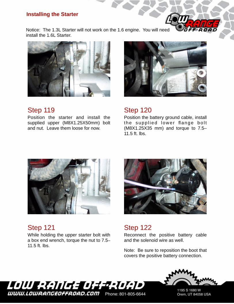
Step 120Position the battery ground cable, install t he supp l i ed l owe r flange bo l t (M8X1.25X35 mm) and torque to 7.5–11.5 ft. lbs.
Step 121While holding the upper starter bolt with a box end wrench, torque the nut to 7.5–11.5 ft. lbs.
Step 119Position the starter and install the supplied upper (M8X1.25X50mm) bolt and nut. Leave them loose for now.
Installing the Starter
Step 122Reconnect the positive battery cable and the solenoid wire as well.
Note: Be sure to reposition the boot that covers the positive battery connection.
Notice: The 1.3L Starter will not work on the 1.6 engine. You will need install the 1.6L Starter.
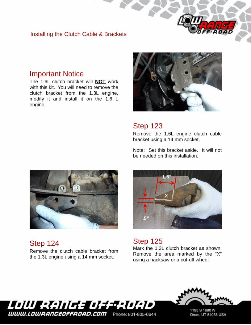
Step 124Remove the clutch cable bracket from the 1.3L engine using a 14 mm socket.
Important NoticeThe 1.6L clutch bracket will NOT work with this kit. You will need to remove the clutch bracket from the 1.3L engine, modify it and install it on the 1.6 L engine.
Step 123Remove the 1.6L engine clutch cable bracket using a 14 mm socket.
Note: Set this bracket aside. It will not be needed on this installation.
Step 125Mark the 1.3L clutch bracket as shown. Remove the area marked by the “X” using a hacksaw or a cut-off wheel.
Installing the Clutch Cable & Brackets
X
1.5”
.5”
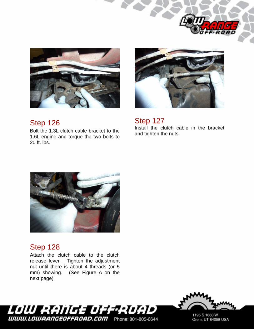
Step 126Bolt the 1.3L clutch cable bracket to the 1.6L engine and torque the two bolts to 20 ft. lbs.
Step 127Install the clutch cable in the bracket and tighten the nuts.
Step 128Attach the clutch cable to the clutch release lever. Tighten the adjustment nut until there is about 4 threads (or 5 mm) showing. (See Figure A on the next page)
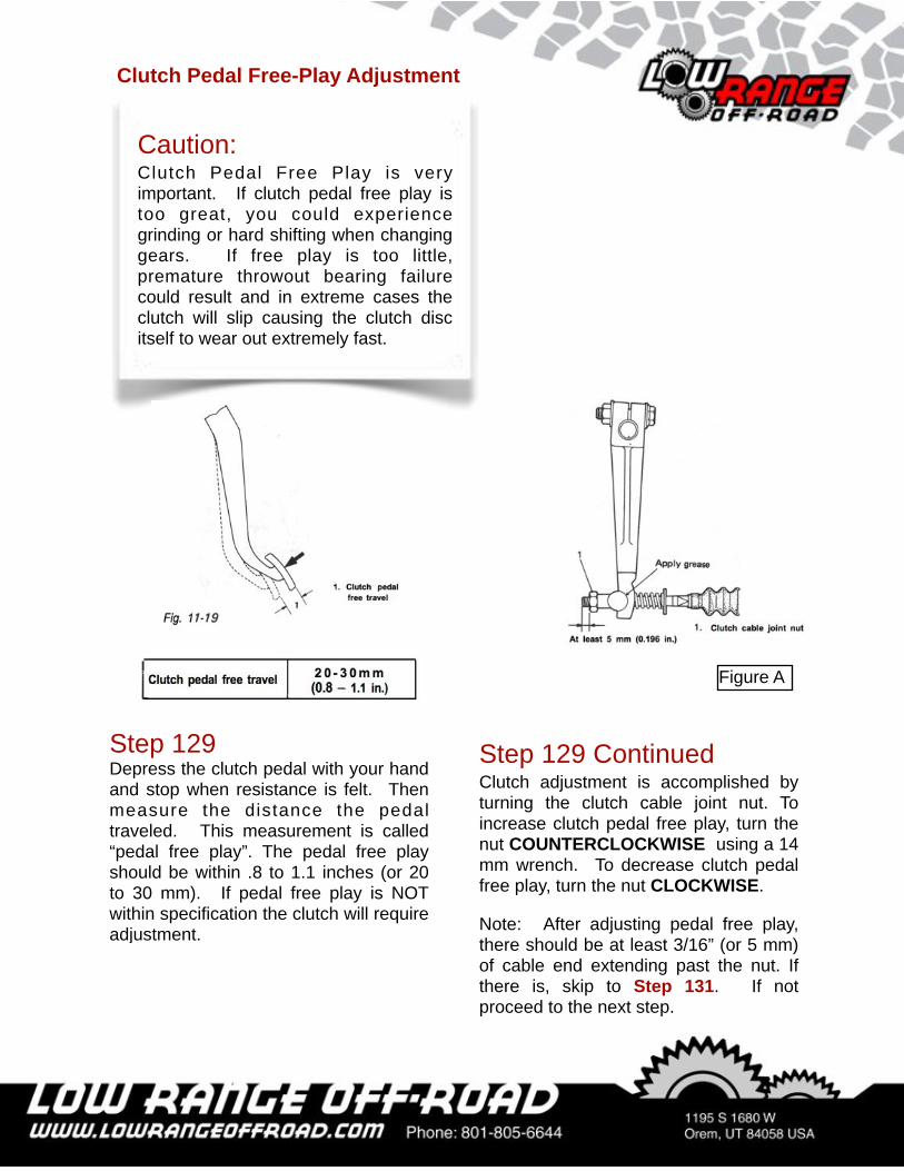
Caution:Clutch Pedal Free Play is very important. If clutch pedal free play is too great, you could experience grinding or hard shifting when changing gears. If free play is too little, premature throwout bearing failure could result and in extreme cases the clutch will slip causing the clutch disc itself to wear out extremely fast.
Clutch Pedal Free-Play Adjustment
Step 129Depress the clutch pedal with your hand and stop when resistance is felt. Then measure the distance the pedal traveled. This measurement is called “pedal free play”. The pedal free play should be within .8 to 1.1 inches (or 20 to 30 mm). If pedal free play is NOT within specification the clutch will require adjustment.
Step 129 ContinuedClutch adjustment is accomplished by turning the clutch cable joint nut. To increase clutch pedal free play, turn the nut COUNTERCLOCKWISE using a 14 mm wrench. To decrease clutch pedal free play, turn the nut CLOCKWISE.
Note: After adjusting pedal free play, there should be at least 3/16” (or 5 mm) of cable end extending past the nut. If there is, skip to Step 131. If not proceed to the next step.
Figure A
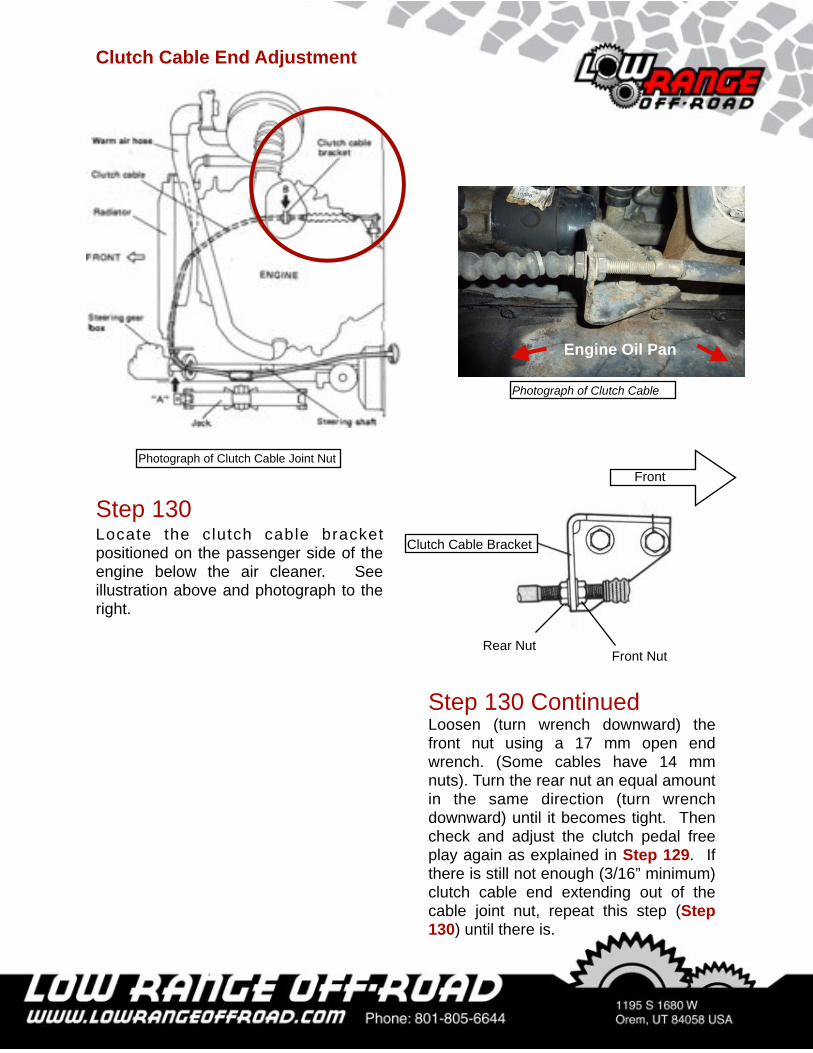
Clutch Cable End Adjustment
Photograph of Clutch Cable Joint Nut
Step 130Locate the clutch cable bracket positioned on the passenger side of the engine below the air cleaner. See illustration above and photograph to the right.
Photograph of Clutch Cable
Engine Oil Pan
Step 130 ContinuedLoosen (turn wrench downward) the front nut using a 17 mm open end wrench. (Some cables have 14 mm nuts). Turn the rear nut an equal amount in the same direction (turn wrench downward) until it becomes tight. Then check and adjust the clutch pedal free play again as explained in Step 129. If there is still not enough (3/16” minimum) clutch cable end extending out of the cable joint nut, repeat this step (Step 130) until there is.
Front
Clutch Cable Bracket
Front NutRear Nut
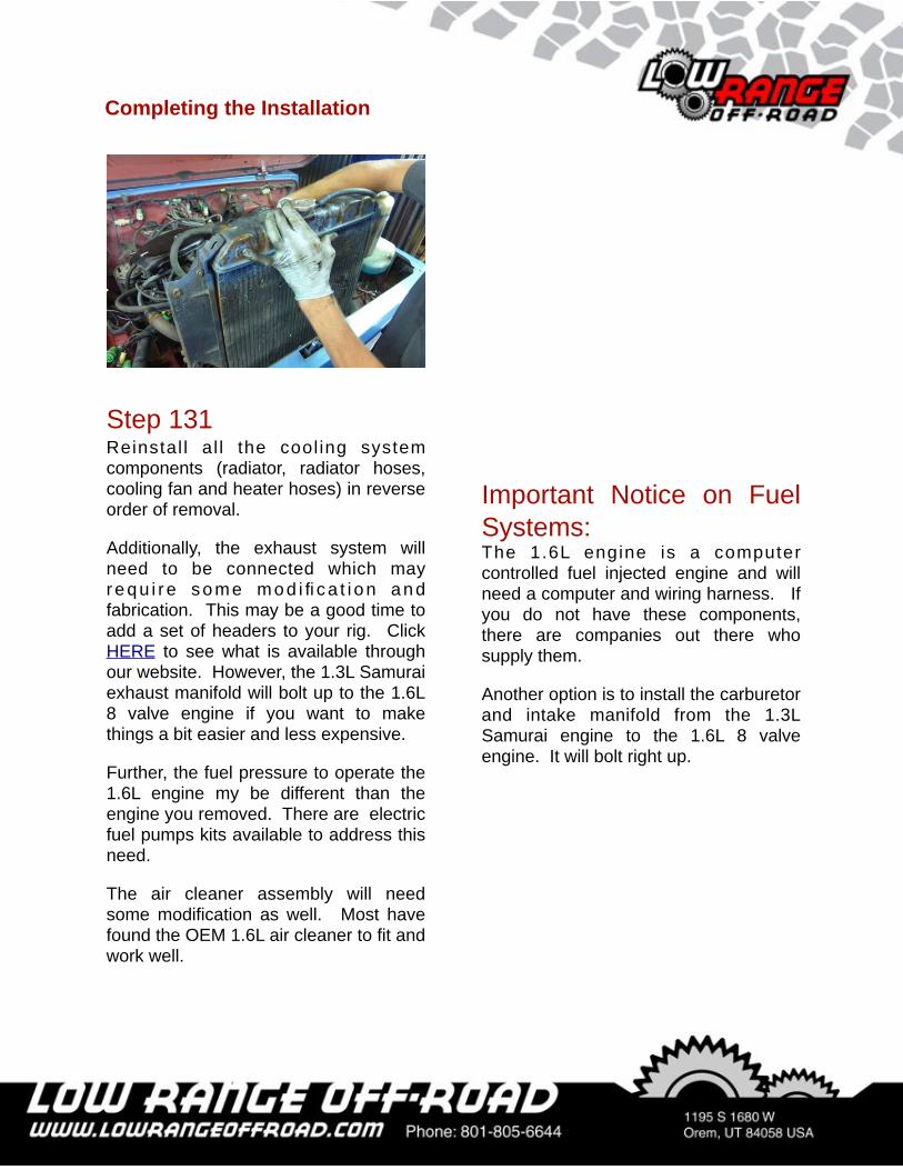
Step 131Reinstal l al l the cool ing system components (radiator, radiator hoses, cooling fan and heater hoses) in reverse order of removal.
Additionally, the exhaust system will need to be connected which may requ i r e some mod i fica t i on and fabrication. This may be a good time to add a set of headers to your rig. Click HERE to see what is available through our website. However, the 1.3L Samurai exhaust manifold will bolt up to the 1.6L 8 valve engine if you want to make things a bit easier and less expensive.
Further, the fuel pressure to operate the 1.6L engine my be different than the engine you removed. There are electric fuel pumps kits available to address this need.
The air cleaner assembly will need some modification as well. Most have found the OEM 1.6L air cleaner to fit and work well.
Important Notice on Fuel Systems:The 1.6L engine is a computer controlled fuel injected engine and will need a computer and wiring harness. If you do not have these components, there are companies out there who supply them.
Another option is to install the carburetor and intake manifold from the 1.3L Samurai engine to the 1.6L 8 valve engine. It will bolt right up.
Completing the Installation
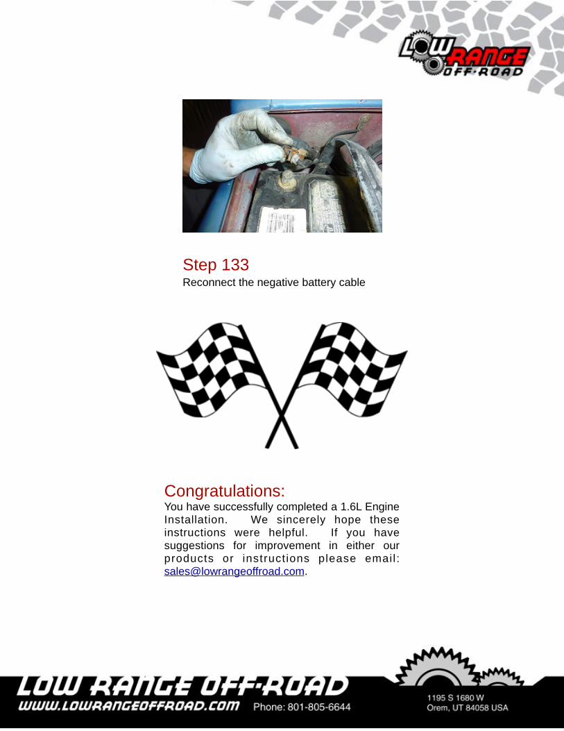
Step 133Reconnect the negative battery cable
Congratulations:You have successfully completed a 1.6L Engine Installation. We sincerely hope these instructions were helpful. If you have suggestions for improvement in either our products or instructions please email: [email protected].

As always, If you experience any difficulty during the installation of this product please contact Low Range Off-Road Technical Support at 801-805-6644 M-F 8am-5pm MST. Thank you for purchasing from Low Range Off-Road.
These instructions are designed as a general installation guide. Installation of many Low Range Off-Road products require specialized skills such as metal fabrication, welding and mechanical trouble shooting. If you have any questions or are unsure about how to proceed, please contact our shop at 801-805-6644 or seek help from a competent fabricator. Using fabrication tools such as welders, torches and grinders can cause serious bodily harm and death. Please operate equipment carefully and observe proper safety procedures.
Rock crawling and off-road driving are inherently dangerous activities. Some modifications will adversely affect the on-road handling characteristics of your vehicle. All products sold by Low Range Off-Road are sold for off road use only. Any other use or application is the responsibility of the purchaser and/or user. Some modifications and installation of certain aftermarket parts may under certain circumstances void your original dealer warranty. Modification of your vehicle may create dangerous conditions, which could cause roll-overs resulting in serious bodily injury or death. Buyers and users of these products hereby expressly assume all risks associated with any such modifications and use.
Revised 07/09/13© Copyright 2013 Low Range Off-Road, LC All Rights Reserved

![1.6L 4-CYL - VIN [E] - TexasNissans.comtexasnissans.com/fsm/Sentra/1993/1.6l 4 cyl.pdf · 1.6L 4-CYL - VIN [E] 1993 Nissan Sentra 1993 NISSAN ENGINES 1.6L 4-Cylinder ... on timing](https://img.pdfslide.net/doc/110x75/5ae38e697f8b9a0d7d8dcc83/16l-4-cyl-vin-e-4-cylpdf16l-4-cyl-vin-e-1993-nissan-sentra-1993-nissan.jpg)


![1.3L 4-CYL - VIN [3] & 1.6L 4-CYL - VIN [0] - VALVULITA · 1.3L 4-CYL - VIN [3] & 1.6L 4-CYL - VIN [0] 1992 Suzuki Swift 1992 SUZUKI ENGINES ... (TDC) timing mark of timing belt cover](https://img.pdfslide.net/doc/110x75/5ae38e697f8b9a0d7d8dcc8f/13l-4-cyl-vin-3-16l-4-cyl-vin-0-valvulita-4-cyl-vin-3-16l-4-cyl.jpg)