Embed Size (px)
Citation preview
SFI Specification 16.6 Page 1 Effective: April 20, 2018
Copyright © 2018 by the SFI Foundation, Inc. All rights reserved. Reproduction in any form without written permission of SFI is prohibited.
SFI SPECIFICATION 16.6 EFFECTIVE: APRIL 20, 2018* PRODUCT: Advanced Motorsport Restraint Assemblies 1.0 GENERAL INFORMATION
1.1 This SFI Specification establishes uniform test procedures and minimum standards for evaluating and determining performance capabilities for Advanced Motorsport Restraint Assemblies used by individuals engaged in competitive motorsports.
1.2 The procedures, test evaluations and standards contained herein, are
intended only as minimum guidelines for construction and evaluation of products. Certification that products meet such minimum standards is made by the product manufacturer and products are not certified, endorsed or approved by SFI under this program.
1.3 Use of the "This Manufacturer Certifies That This Product Meets SFI
Specification 16.6" logo/designation, the authorized artwork style, or conventional lettering by a manufacturer, on a subject product, is intended only to indicate that the manufacturer of the product has represented that they have submitted the product to the recommended tests, with positive results, in compliance with the standards established herein.
1.4 This SFI Specification requires a demonstration that the product of a
manufacturer meets or exceeds the requirements when the manufacturer enters the program; and on an annual basis thereafter. Any manufacturer may participate in the program by providing Advanced Motorsport Restraint Assemblies that meet or exceed the SFI Specification 16.6 test standards, by complying with the requirements of the SFI Specification 16.6 program, and by signing a licensing agreement with the SFI Foundation, Inc.
1.5 Compliance with this specification is entirely voluntary. However, when a
manufacturer provides Advanced Motorsport Restraint Assemblies in compliance with all requirements of the SFI Specification 16.6 and enters into the licensing agreement with the SFI Foundation, Inc., they may certify that
SFI Specification 16.6 Page 2 Effective: April 20, 2018
Copyright © 2018 by the SFI Foundation, Inc. All rights reserved. Reproduction in any form without written permission of SFI is prohibited.
compliance with such standards is in accordance with the guidelines established herein.
1.6 Manufacturers wishing to participate in the program, in addition to the other
requirements of this specification, must label each of their products with the manufacturer's name, trademark or symbol as well as the date of manufacture of the product.
1.7 No manufacturer may display the SFI logo/designation on their product
unless the manufacturer has signed a licensing agreement with SFI and has successfully complied with all the requirements of this specification and the self-certification program.
1.8 Any restraint assembly pertaining to this specification shall remain as
constructed by the original manufacturer and shall not be modified or altered by anyone else.
2.0 DEFINITIONS
2.1 Advanced Motorsport Restraint Assembly: An Advanced Motorsport Restraint Assembly is used to secure an occupant within a seat, vehicle roll cage or cockpit structure with the objective of minimizing injury during accident conditions.
2.2 Useful Life: The useful life of an Advanced Motorsport Restraint Assembly
shall not exceed two years from the date of manufacture and must be replaced at or before that time.
2.3 Body Block: A device constructed of wood, metal or any other appropriate
combination of materials which approximates the torso of an average size male and must be adequately designed to withstand all Advanced Motorsport Restraint Assembly test loads prescribed in this spec. The Body Block shall conform to all dimensions and descriptions described in Figure 2 of this specification.
2.4 Installation Instructions: Manufacturer’s installation instructions provide
detailed user system set up directions including approved combinations of belts sub-assemblies, approved installation angles, approved methods of installing fixed and active adjusters (including weaving), and approved methods of installing mounting hardware.
SFI Specification 16.6 Page 3 Effective: April 20, 2018
Copyright © 2018 by the SFI Foundation, Inc. All rights reserved. Reproduction in any form without written permission of SFI is prohibited.
3.0 SYSTEM CONSTRUCTION DEFINITIONS
3.1 DRIVER RESTRAINT SYSTEM
An assembly, which includes a Lap Belt, Individual or double (over/under) Shoulder Belts (a total of two or four Shoulder Belts), two Anti-Submarine Belts, one Negative G Belt, one Release Buckle, Attachment Hardware, and Adjustment Hardware. Possible configurations may only result in a seven or nine point restraint system. 3.2 LAP BELTS A belt assembly designed to restrain the pelvis. It may include the Release Buckle mechanism along with the Adjustment and Attachment Hardware. 3.3 SHOULDER BELTS Individual or double (over/under) belts for each shoulder, designed to restrain the upper torso and shoulder area. The Shoulder Belts must be attached to the seat or roll cage on the upper end and to the release buckle on the lower end with Adjustment Hardware on the webbing in between. Sternum cross belts are not permitted. Double (over/under) Shoulder Belts must have a common left and right side connection at the Release Buckle. 3.4 ANTI-SUBMARINE BELTS A two belt assembly designed to limit the forward motion of the pelvis while preventing the lap belt from riding up from the pelvis. The Anti-Submarine Belts may be configured to be mounted under the buttocks with each belt passing up through the groin area and attaching to the Release Buckle or passing through d-rings on the Lap Belt and looping over the Shoulder Belt Release Buckle tabs or looping over the Lap Belt Release Buckle tabs. 3.5 NEGATIVE G BELT A single belt assembly, which may be part of the anti-submarine belt assembly, designed to properly position the Release Buckle and to also limit vertical occupant excursion. The Negative G Belt can be configured to be mounted to the seat or the roll cage on the lower end and to the Release Buckle on the upper end.
SFI Specification 16.6 Page 4 Effective: April 20, 2018
Copyright © 2018 by the SFI Foundation, Inc. All rights reserved. Reproduction in any form without written permission of SFI is prohibited.
3.6 RELEASE BUCKLE The Release Buckle must provide a common connection for the Lap Belts, Shoulder Belts, Anti-Submarine Belts and the Negative G Belt and must be designed with a quick and easy one-handed, gloved release of all belts in all conditions, Shoulder Belts and Anti-Submarine or Negative G Belts may not be connected to Lap Belts with permanently attached hardware. Clear markings denoting the manufacturer and date of manufacture must be permanently marked on the hardware. It must have one (1) of two (2) release designs:
(A) Latch/Lever: Utilizes a lever opening away from the body in a right to left hand movement, parallel to the lap belt with a complete release of all belts. Lever must have a provision to prevent an unintentional release.
(B) Cam Lock: A circular handle or raised surface that turns in either direction for a motion of not less than 30 degrees before completely releasing all belts, except the permanently attached hardware. A downward facing tab or toggle may be used, provided that its length does not extend more than ½ inch beyond the outer diameter of the release mechanism unless a provision to prevent unintentional rotation or release is provided.
3.7 ADJUSTMENT HARDWARE Adjustment Hardware is used for adjusting the length of the individual belts by the end user. Clear markings denoting the manufacturer and date of manufacture must be permanently marked on the hardware. There are two types of Adjustment Hardware:
Fixed Adjuster: A Fixed Adjuster contains no moving parts and must be made of magnetic steel. 2, 3 or 4-bar locking adjusters, wrapped in accordance with the manufacturer’s instructions, are examples of a Fixed Adjuster and may be used near the Attachment Hardware or be combined into the Attachment Hardware. Pinch plates consisting of two identical brackets with the webbing wrapped through the plates and bolted to a mounting point also constitute a Fixed Adjuster.
Active Adjuster: An Active Adjuster constitutes one of more parts which when combined into an assembly allow user belt length adjustment. Roller adjusters and tilt-lock adjusters are examples of Active Adjusters. Active Adjusters may be used mid-belt on the Shoulder Belts, Lap Belts, Anti-Submarine Belts and the Negative G Belt. Active Adjusters may also be directly attached to the Release Buckle attachment tab with no webbing loop. All roller adjusters must use a tension spring as a part of the designed assembly if the belt uses the roller adjuster in mid-belt.
SFI Specification 16.6 Page 5 Effective: April 20, 2018
Copyright © 2018 by the SFI Foundation, Inc. All rights reserved. Reproduction in any form without written permission of SFI is prohibited.
3.8 ATTACHMENT HARDWARE Attachment Hardware must be magnetic steel and use a minimum 3/8 inch diameter bolt hole to secure the belt mount locations. The belt material may be folded inward to pass through the mounting tab slot. With the exception of Negative G belt Attachment Hardware, Attachment Hardware mounting tab webbing slots must be a minimum of 2.0 inches (50.8 mm) wide for all webbing of 2 inch (nominal) and greater width, and slots must be a minimum of 1.75 inch (44.5) wide for 1.75 inch (nominal) webbing. Wrap around type mounts may be used on Shoulder Belts that do not cross behind the driver and on Anti-Submarine Belts and Negative G Belts but not on Lap Belts. Wrap around type mounts must terminate in a Fixed Adjuster type attachment, threaded to manufacturer’s instructions, or be sewn webbing loops. Attachment Hardware for Lap Belts must allow the Lap Belts to swivel or self-align. Clip-on mounts and eyebolts attachment may not be used. Clear markings denoting manufacturer and date of manufacture must be permanently marked on the hardware. 3.9 PHYSICAL MEASUREMENT OF HARDWARE
A. Hardware Edge Finish: All peripheral hardware edges that can contact the webbing must be free from burrs and sharp edges that may cause tearing of the webbing. All peripheral hardware edges must have a minimum radius of 0.025 inch (0.6 mm). All other hardware edges must be free from burrs and sharp edges.
B. Hardware Dimensions: Hardware thickness, slot lengths, widths, hole sizes and clearances on moving components must be measured and recorded.
3.10 BELT SUB-ASSEMBLY A Belt Sub-Assembly is any combination of components which may include Belt Webbing, Adjustment Hardware, Attachment Hardware or Buckle Release which forms a load carrying portion of an Advanced Motorsport Restraint Assembly.
3.11 WEBBING
3.11.1 MATERIAL PROPERTIES
A. Shoulder, Lap and Anti-submarine Belt Webbing: must be a woven narrow fabric manufactured with continuous filament yarns. The yarns used in the manufacture of the webbing shall be bright, high tenacity, light and heat resistant. Webbing must be produced of Polyester yarns. The ends of the webbing must be protected or treated to prevent raveling. The free end of the belts must not freely pull out of the adjustment hardware when fully adjusted to the maximum length.
SFI Specification 16.6 Page 6 Effective: April 20, 2018
Copyright © 2018 by the SFI Foundation, Inc. All rights reserved. Reproduction in any form without written permission of SFI is prohibited.
B. Negative G Belt Webbing: if a woven narrow fabric, it must be manufactured with continuous filament yarns and the yarns used in the manufacture of the webbing shall be bright, high tenacity, light and heat resistant. The ends of the webbing must be protected or treated to prevent raveling. The free end of the belts must not freely pull out of the adjustment hardware when fully adjusted to the maximum length. The Negative G Belt must be non-metallic and flexible.
3.11.2 MINIMUM DIMENSIONS
A. Shoulder, Lap and Anti-Submarine Belt webbing width must be a minimum of 1.72 inches (43.7 mm) and a maximum of 3.10 inches (78.7 mm). B. Negative G Belt webbing
1. Containing any Active Adjuster Adjustment Hardware: Webbing must be woven narrow fabric produced of Polyester yarns and must be a minimum width 1.72 inches (43.7 mm) and a maximum of 3.10 inches (78.7 mm), for the length for which it may pass through the Adjustment Hardware, elsewhere it may be folded to reduce its width. 2. With no Adjustment Hardware: must be a minimum width of 0.75 inches (19.1 mm) (finished) if woven narrow fabric webbing or a minimum diameter of 0.31 inches (7.9 mm) if round.
3.12 LABELS All labels must be sewn on the webbing in an area that is not in contact with, and cannot come in contact with, any Release Buckle, Adjustment Hardware or Attachment Hardware.
4.0 MODEL CLASSIFICATION Any variation of assembly or component dimensions (except length of webbing), materials, construction design, release buckle design, adjustment hardware design or attachment hardware design is considered a model change.
SFI Specification 16.6 Page 7 Effective: April 20, 2018
Copyright © 2018 by the SFI Foundation, Inc. All rights reserved. Reproduction in any form without written permission of SFI is prohibited.
5.0 TESTING
Test samples shall be fully processed, new restraint assemblies which are representative of restraint assemblies currently produced or to be produced. All Attachment Hardware shall be tested with the corresponding restraint webbing during the assembly testing. Test samples must include Installation Instructions per paragraph 2.4. Webbing shall be tested for breaking strength and abrasion resistance for initial design validation of webbing, upon periodic revalidation of webbing when due, and upon any variation or change in webbing width and/or webbing type used by the manufacturer. It is not necessary to retest webbing in conjunction with each restraint assembly model submitted if there has been no variation made in webbing width or type and if webbing test certification reports are current. Any information not supplied herein shall be taken from Aerospace Standard “SAE AS 8043 – Torso Restraint Systems”.
5.1 BREAKING STRENGTH – WEBBING Test in accordance with SAE AS 8043 unless otherwise specified.
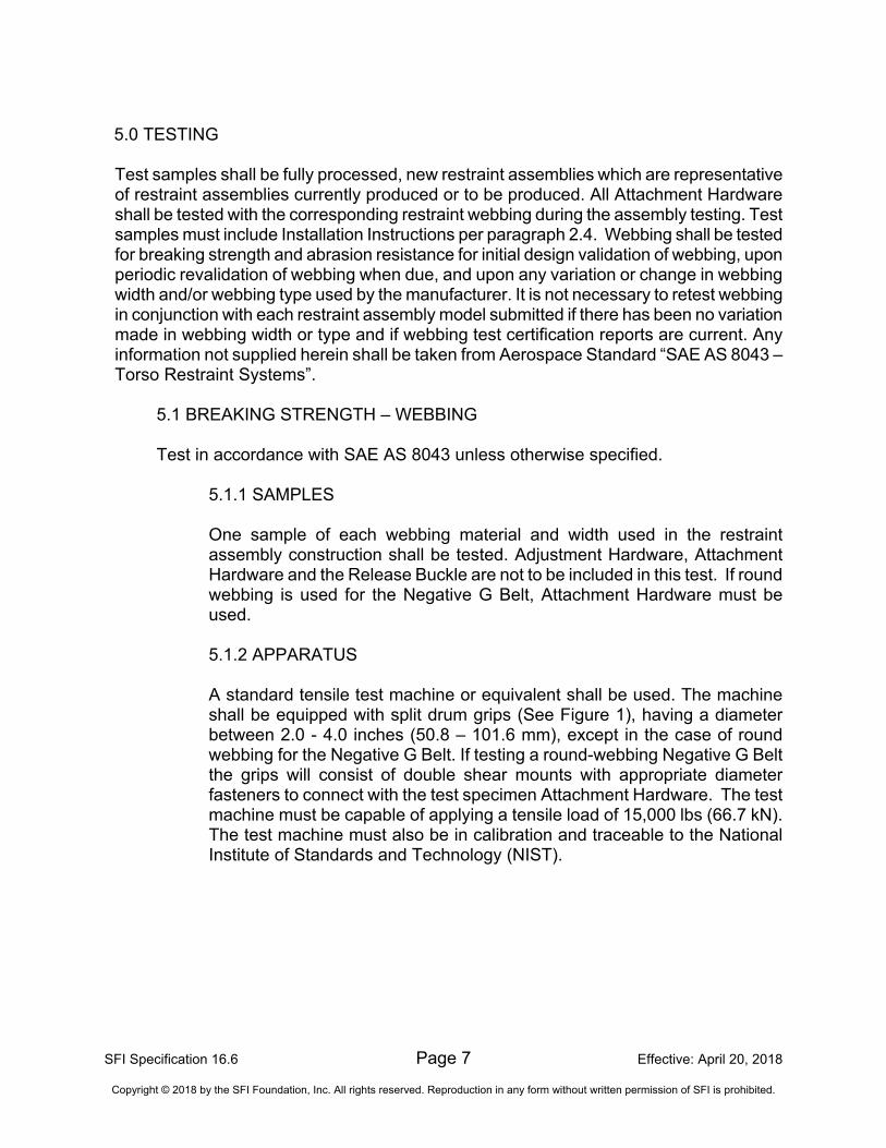
5.1.1 SAMPLES One sample of each webbing material and width used in the restraint assembly construction shall be tested. Adjustment Hardware, Attachment Hardware and the Release Buckle are not to be included in this test. If round webbing is used for the Negative G Belt, Attachment Hardware must be used. 5.1.2 APPARATUS A standard tensile test machine or equivalent shall be used. The machine shall be equipped with split drum grips (See Figure 1), having a diameter between 2.0 - 4.0 inches (50.8 – 101.6 mm), except in the case of round webbing for the Negative G Belt. If testing a round-webbing Negative G Belt the grips will consist of double shear mounts with appropriate diameter fasteners to connect with the test specimen Attachment Hardware. The test machine must be capable of applying a tensile load of 15,000 lbs (66.7 kN). The test machine must also be in calibration and traceable to the National Institute of Standards and Technology (NIST).
SFI Specification 16.6 Page 8 Effective: April 20, 2018
Copyright © 2018 by the SFI Foundation, Inc. All rights reserved. Reproduction in any form without written permission of SFI is prohibited.
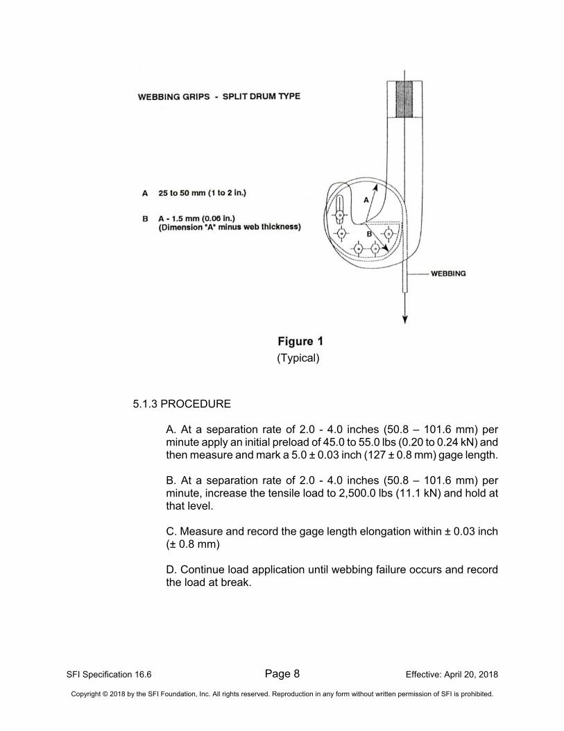
5.1.3 PROCEDURE
A. At a separation rate of 2.0 - 4.0 inches (50.8 – 101.6 mm) per minute apply an initial preload of 45.0 to 55.0 lbs (0.20 to 0.24 kN) and then measure and mark a 5.0 ± 0.03 inch (127 ± 0.8 mm) gage length. B. At a separation rate of 2.0 - 4.0 inches (50.8 – 101.6 mm) per minute, increase the tensile load to 2,500.0 lbs (11.1 kN) and hold at that level. C. Measure and record the gage length elongation within ± 0.03 inch (± 0.8 mm) D. Continue load application until webbing failure occurs and record the load at break.
(Typical)
SFI Specification 16.6 Page 9 Effective: April 20, 2018
Copyright © 2018 by the SFI Foundation, Inc. All rights reserved. Reproduction in any form without written permission of SFI is prohibited.
5.2 RESTRAINT ASSEMBLY TEST
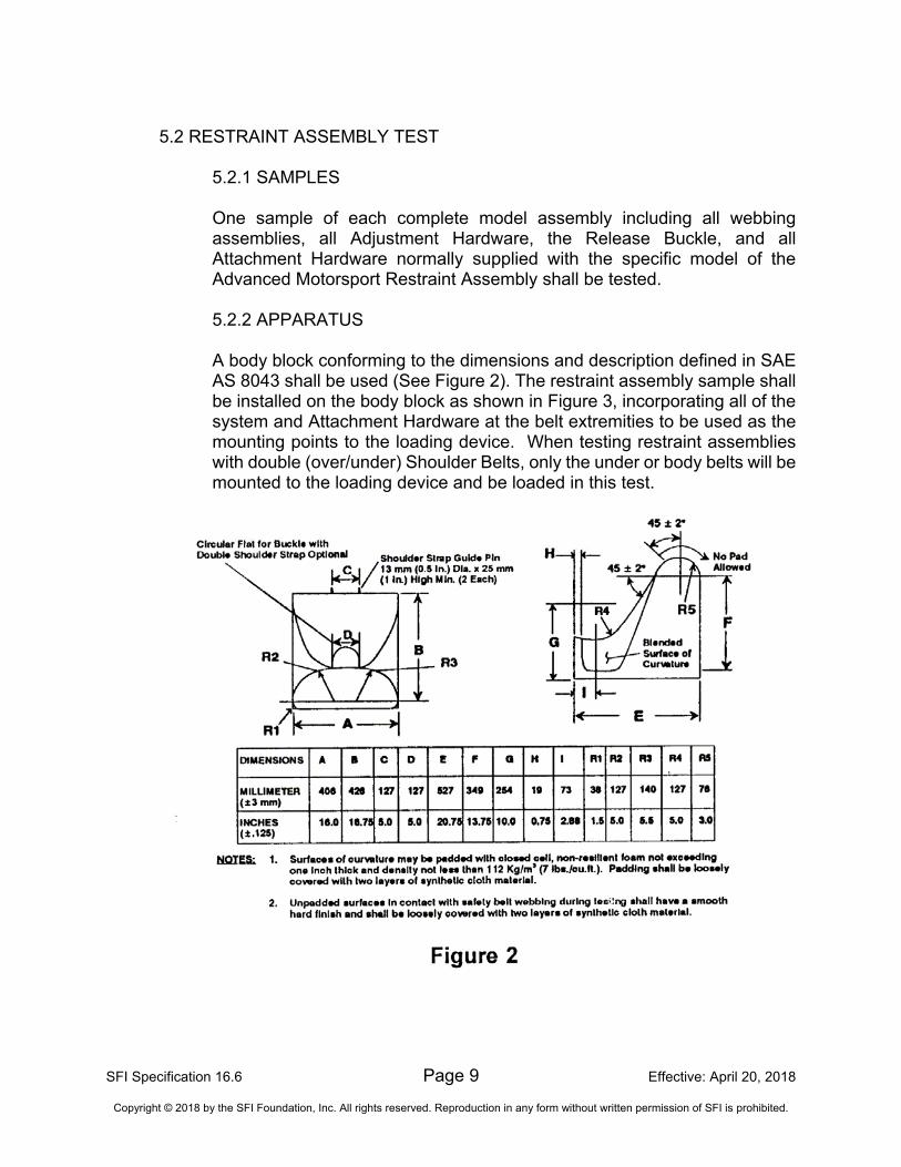
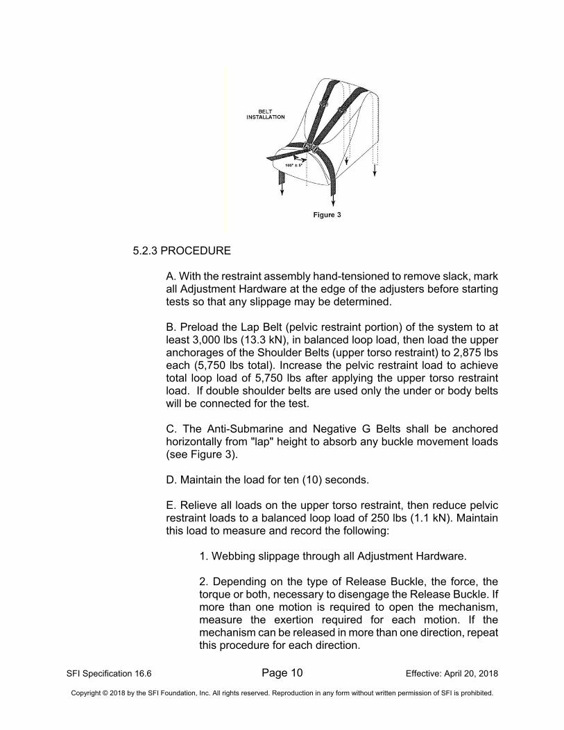
5.2.1 SAMPLES One sample of each complete model assembly including all webbing assemblies, all Adjustment Hardware, the Release Buckle, and all Attachment Hardware normally supplied with the specific model of the Advanced Motorsport Restraint Assembly shall be tested. 5.2.2 APPARATUS A body block conforming to the dimensions and description defined in SAE AS 8043 shall be used (See Figure 2). The restraint assembly sample shall be installed on the body block as shown in Figure 3, incorporating all of the system and Attachment Hardware at the belt extremities to be used as the mounting points to the loading device. When testing restraint assemblies with double (over/under) Shoulder Belts, only the under or body belts will be mounted to the loading device and be loaded in this test.
SFI Specification 16.6 Page 10 Effective: April 20, 2018
Copyright © 2018 by the SFI Foundation, Inc. All rights reserved. Reproduction in any form without written permission of SFI is prohibited.
5.2.3 PROCEDURE
A. With the restraint assembly hand-tensioned to remove slack, mark all Adjustment Hardware at the edge of the adjusters before starting tests so that any slippage may be determined.
B. Preload the Lap Belt (pelvic restraint portion) of the system to at least 3,000 lbs (13.3 kN), in balanced loop load, then load the upper anchorages of the Shoulder Belts (upper torso restraint) to 2,875 lbs each (5,750 lbs total). Increase the pelvic restraint load to achieve total loop load of 5,750 lbs after applying the upper torso restraint load. If double shoulder belts are used only the under or body belts will be connected for the test.
C. The Anti-Submarine and Negative G Belts shall be anchored horizontally from "lap" height to absorb any buckle movement loads (see Figure 3).
D. Maintain the load for ten (10) seconds.
E. Relieve all loads on the upper torso restraint, then reduce pelvic restraint loads to a balanced loop load of 250 lbs (1.1 kN). Maintain this load to measure and record the following:
1. Webbing slippage through all Adjustment Hardware.
2. Depending on the type of Release Buckle, the force, the torque or both, necessary to disengage the Release Buckle. If more than one motion is required to open the mechanism, measure the exertion required for each motion. If the mechanism can be released in more than one direction, repeat this procedure for each direction.
SFI Specification 16.6 Page 11 Effective: April 20, 2018
Copyright © 2018 by the SFI Foundation, Inc. All rights reserved. Reproduction in any form without written permission of SFI is prohibited.
Note: If a second or subsequent test on an individual Release Buckle is outside exertion limits, another Release Buckle may be used to test the other release direction(s) not previously tested (i.e. an individual Release Buckle is only required to be within exertion limits for the first test to which it is subjected, but the design must be within exertion limits for each available release direction). F. Examine the webbing for cuts from the Adjustment or Attachment Hardware.
5.3 ABRASION RESISTANCE
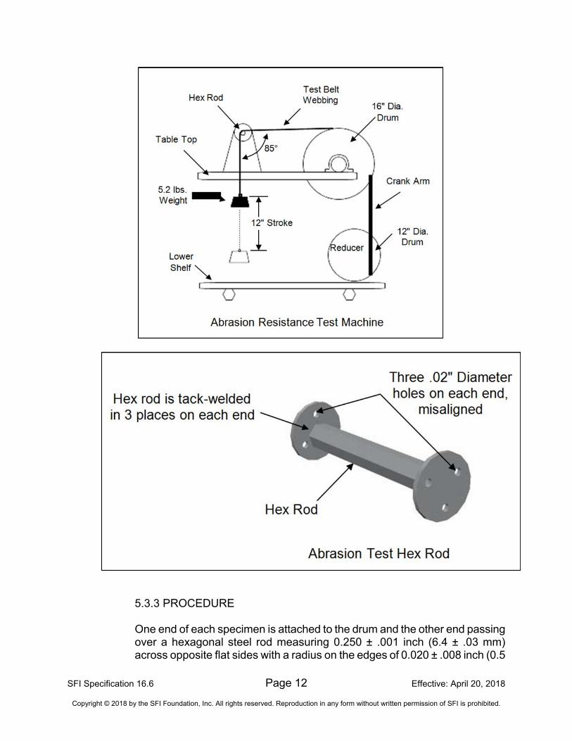
5.3.1 SAMPLES One sample of each webbing width and webbing type used in the Advanced Motorsport Restraint Assembly construction shall be tested. Adjustment Hardware, Attachment Hardware and the Release Buckle are not included in this test. This includes smaller width webbing used in Anti-submarine belt and Negative G belt assemblies. 5.3.2 APPARATUS An abrasion machine in conformance with Fed Test Method 5309 shall be used. It shall consist of a power driven, oscillating drum with an outside diameter of 16.0 inches (406.4 mm).
SFI Specification 16.6 Page 12 Effective: April 20, 2018
Copyright © 2018 by the SFI Foundation, Inc. All rights reserved. Reproduction in any form without written permission of SFI is prohibited.
5.3.3 PROCEDURE One end of each specimen is attached to the drum and the other end passing over a hexagonal steel rod measuring 0.250 ± .001 inch (6.4 ± .03 mm) across opposite flat sides with a radius on the edges of 0.020 ± .008 inch (0.5
SFI Specification 16.6 Page 13 Effective: April 20, 2018
Copyright © 2018 by the SFI Foundation, Inc. All rights reserved. Reproduction in any form without written permission of SFI is prohibited.
± 0.2 mm). The free end shall be attached to a weight of 2.0 lbs ± 2.0 ounces (0.91 kg ± 0.06 kg) for specified breaking strengths under 1,000.0 lbs (4.45 kN). For breaking strengths over 3,000.0 lbs (13.35 kN), the weight shall be 5.2 lbs ± 2.0 ounces (2.4 ± 0.06 kg). During the test, the specimen oscillates over the hexagonal rod for a 12.0 ± 1.0 inches (304.8 ± 25.4 mm) traverse at the rate of 60 ± 2 strokes (30 ± 1 cycles) per minute for 5,000 strokes (2,500 cycles). After conclusion of the 5,000 strokes, the specimen(s) shall be tested as described in paragraph 5.1 of specification, except there is no requirement to determine elongation.
5.4 ACTIVE ADJUSTER MICRO-SLIP TEST
5.4.1 SAMPLES Two samples of each type of Active Adjuster used in the assembly shall be tested. Each test sample shall consist of a single length of belt webbing with the Active Adjuster in the middle of the belt, and Attachment Hardware at one end of the webbing. The Active Adjuster shall be a minimum of 8.0 inches (203.2 mm) from the end Attachment Hardware, except in the case of an Active Adjuster which also serves as a Release Buckle attachment tab. 5.4.2 APPARATUS The abrasion resistance test fixture described in Paragraph 5.3.2 above shall be used for the micro-slip test. 5.4.3 PROCEDURE
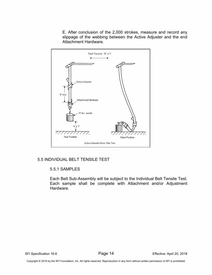
A. Attach the free end of the entire webbing test specimen to the drum fixture, with an 11 lbs. weight hooked to the lower end attachment as shown in the figure below. The free end of the webbing coming from the Active Adjuster shall in no way be attached or clipped to the section under load.
B. Before the actual start of the test, a series of 20 cycles shall be completed so that the self-tightening system settles properly.
C. Mark the webbing at the edge of the Active Adjuster before starting the actual test so that any slippage may be determined.
D. Begin the test by raising and lowering the test load so the test sample goes from taut to slack. The sample shall oscillate in this manner for a 12.0 ± 1.0 inches (304.8 ± 25.4 mm) total traverse at the rate of 60 ± 2 strokes (30 ± 1 cycles) per minute for 2,000 strokes (1,000 cycles). The 11.0 lbs (5.0 kg) load shall be raised 4.0 ± 1.0 inches (101.6 ± 25.4 mm) for each cycle.
SFI Specification 16.6 Page 14 Effective: April 20, 2018
Copyright © 2018 by the SFI Foundation, Inc. All rights reserved. Reproduction in any form without written permission of SFI is prohibited.
E. After conclusion of the 2,000 strokes, measure and record any slippage of the webbing between the Active Adjuster and the end Attachment Hardware.
5.5 INDIVIDUAL BELT TENSILE TEST
5.5.1 SAMPLES Each Belt Sub-Assembly will be subject to the Individual Belt Tensile Test. Each sample shall be complete with Attachment and/or Adjustment Hardware.
SFI Specification 16.6 Page 15 Effective: April 20, 2018
Copyright © 2018 by the SFI Foundation, Inc. All rights reserved. Reproduction in any form without written permission of SFI is prohibited.
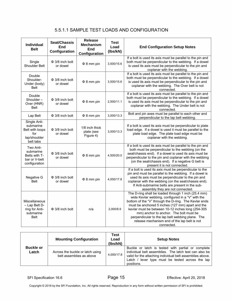
5.5.1.1 SAMPLE TEST LOADS AND CONFIGURATION
Individual Belt
Seat/Chassis End
Configuration
Release Mechanism
End Configuration
Test Load
(lbs/kN) End Configuration Setup Notes
Single Shoulder Belt
Φ 3/8 inch bolt or dowel
Φ 8 mm pin 3,500/15.6
If a bolt is used its axis must be parallel to the pin and both must be perpendicular to the webbing. If a dowel is used its axis must be perpendicular to the pin and
coplanar with the webbing.
Double Shoulder-
Under (body) Belt
Φ 3/8 inch bolt or dowel
Φ 8 mm pin 3,500/15.6
If a bolt is used its axis must be parallel to the pin and both must be perpendicular to the webbing. If a dowel is used its axis must be perpendicular to the pin and
coplanar with the webbing. The Over belt is not connected.
Double Shoulder – Over (HNR)
Belt
Φ 3/8 inch bolt or dowel
Φ 8 mm pin 2,500/11.1
If a bolt is used its axis must be parallel to the pin and both must be perpendicular to the webbing. If a dowel is used its axis must be perpendicular to the pin and
coplanar with the webbing. The Under belt is not connected.
Lap Belt Φ 3/8 inch bolt Φ 8 mm pin 3,000/13.3 Bolt and pin axes must be parallel to each other and
perpendicular to the lap belt webbing. Single Anti-submarine
Belt with loops for
lap/shoulder belt tabs
Φ 3/8 inch bolt or dowel
1/8 inch thick plate (see Figure 4)
3,000/13.3
If a bolt is used its axis must be perpendicular to plate load edge. If a dowel is used it must be parallel to the
plate load edge. The plate load edge must be coplanar with the webbing.
Two Anti-submarine
Belts with T-bar or V-belt configuration
Φ 3/8 inch bolt or dowel
Φ 8 mm pin 4,500/20.0
If a bolt is used its axis must be parallel to the pin and both must be perpendicular to the webbing (on the
seat/chassis end). If a dowel is used its axis must be perpendicular to the pin and coplanar with the webbing
(on the seat/chassis end). If a negative G belt is present it is not connected.
Negative G Belt
Φ 3/8 inch bolt or dowel
Φ 8 mm pin 4,000/17.8
If a bolt is used its axis must be perpendicular to the pin and must be parallel to the webbing. If a dowel is
used its axis must be perpendicular to the pin and coplanar with the webbing (on the seat/chassis end).
If Anti-submarine belts are present in the sub-assembly they are not connected.
Miscellaneous – Lap Belt D-ring for Anti-submarine
Belt
Φ 3/8 inch bolt n/a 2,000/8.9
The D-ring shall be loaded through 1 inch (25.4 mm) wide Kevlar webbing, configured in a “V” with the
bottom of the “V” through the D-ring. The Kevlar ends must be anchored 5 inches (127 mm) apart and the kevlar must be between 10-12 inches long (254-305
mm) anchor to anchor. The bolt must be perpendicular to the lap belt webbing plane. The
release mechanism end of the lap belt is not connected.
Buckle or Latch
Mounting Configuration
Test Load
(lbs/kN)
Setup Notes
Across the buckle or latch using
belt assemblies as above
4,000/17.8
Buckle or latch is tested with partial or complete individual belt assemblies. The latch test can also be valid for the attaching individual belt assemblies above. Latch / lever type must be tested across the lap positions.
SFI Specification 16.6 Page 16 Effective: April 20, 2018
Copyright © 2018 by the SFI Foundation, Inc. All rights reserved. Reproduction in any form without written permission of SFI is prohibited.
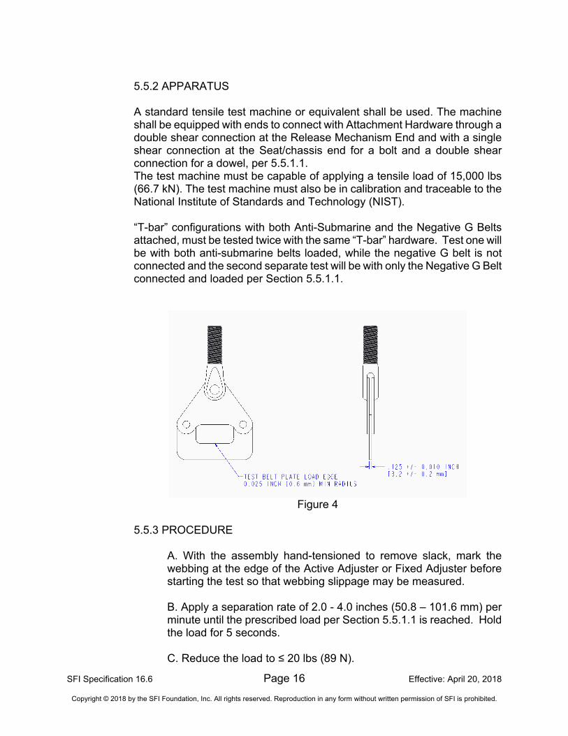
5.5.2 APPARATUS A standard tensile test machine or equivalent shall be used. The machine shall be equipped with ends to connect with Attachment Hardware through a double shear connection at the Release Mechanism End and with a single shear connection at the Seat/chassis end for a bolt and a double shear connection for a dowel, per 5.5.1.1. The test machine must be capable of applying a tensile load of 15,000 lbs (66.7 kN). The test machine must also be in calibration and traceable to the National Institute of Standards and Technology (NIST). “T-bar” configurations with both Anti-Submarine and the Negative G Belts attached, must be tested twice with the same “T-bar” hardware. Test one will be with both anti-submarine belts loaded, while the negative G belt is not connected and the second separate test will be with only the Negative G Belt connected and loaded per Section 5.5.1.1.
Figure 4
5.5.3 PROCEDURE
A. With the assembly hand-tensioned to remove slack, mark the webbing at the edge of the Active Adjuster or Fixed Adjuster before starting the test so that webbing slippage may be measured. B. Apply a separation rate of 2.0 - 4.0 inches (50.8 – 101.6 mm) per minute until the prescribed load per Section 5.5.1.1 is reached. Hold the load for 5 seconds. C. Reduce the load to ≤ 20 lbs (89 N).
SFI Specification 16.6 Page 17 Effective: April 20, 2018
Copyright © 2018 by the SFI Foundation, Inc. All rights reserved. Reproduction in any form without written permission of SFI is prohibited.
D. Apply a separation rate of 2.0 - 4.0 inches (50.8 – 101.6 mm) per minute until the prescribed load per Section 5.5.1.1 is reached. Hold the load for 5 seconds. E. Release the load. F. Measure and record any webbing slippage or deformation at the Adjustment Hardware. (see Section 6.1.11)
6.0 PROOF OF COMPLIANCE Advanced Motorsport Restraint Assembly manufacturers are required to provide the following information to enroll in this program:
6.1 TEST RESULTS Test results shall be documented in a test report.
6.1.1 RELEASE BUCKLE CONSTRUCTION
Identification markings denoting the manufacturer and date of manufacture shall be permanently marked on the hardware and recorded in the test report.
A. The Latch/Lever, if used, shall open from right to left and completely release all belts. The Lever shall have a provision to prevent unintentional release of the latch and belts. B. The Cam Lock, if used, shall turn at least 30° before releasing the belts, except the permanently attached hardware. If a tab or toggle is used, it shall face downward. If a tab or toggle is greater than 0.5" in length, then it shall have a provision to prevent unintentional release.
6.1.2 ADJUSTMENT HARDWARE CONSTRUCTION The test report shall indicate the type of Adjustment Hardware used. If used mid-belt, all roller adjusters must use a tension spring as a part of the designed assembly. Identification markings denoting the manufacturer and date of manufacture shall be permanently marked on the hardware and recorded in the test report.
SFI Specification 16.6 Page 18 Effective: April 20, 2018
Copyright © 2018 by the SFI Foundation, Inc. All rights reserved. Reproduction in any form without written permission of SFI is prohibited.
6.1.3 ATTACHMENT HARDWARE CONSTRUCTION Lap Belts shall not utilize wrap-around type mounts. Wrap-around type mounts (not allowed on Lap or crossing Shoulder Belts) shall terminate in a Fixed Adjuster or sewn webbing loops. Identification markings denoting the manufacturer and date of manufacture shall be permanently marked on the hardware and recorded in the test report. 6.1.4 PHYSICAL MEASUREMENT All Advanced Motorsport Restraint Assembly hardware edges in contact with webbing shall be free from burrs and sharp edges and shall have a minimum radius of 0.025 inch (0.6 mm). All other hardware edges shall be free from burrs and sharp edges. 6.1.5 WEBBING A. Material Properties: Advanced Motorsport Restraint Assemblies must comply with section 3.11.1. B. Minimum Width: Advanced Motorsport Restraint Assemblies must comply with section 3.11.2.
6.1.6 LABELS All labels sewn on the webbing shall not be in contact with any Release Buckle, Adjustment Hardware, or Attachment Hardware. 6.1.7 BREAKING STRENGTH/ELONGATION - WEBBING The breaking strength of Shoulder, Lap and Anti-Submarine Belt webbing sample(s) tested per paragraph 5.1.3 shall be greater than or equal to 7,000 lbs (31.1 kN). The elongation of the Shoulder, Lap and Anti-Submarine Belt webbing sample(s) measured between 50 and 2,500 lbs. (11.1kN) must be between 4% and 16%. The “over” belt webbing of a Double (over/under) Shoulder belt tested per paragraph 5.1.3 shall be greater than or equal to 6,300 lbs (28.0 kN) and must have an elongation between 4% and 16%.
The breaking strength of Negative G belt webbing:
Flat or round webbing: tested per paragraph 5.1.3 shall be greater than or equal to 6,000 lbs (26.7 kN). The elongation of the Negative G Belt webbing sample(s) measured between 50 and 2,500 lbs. (11.1kN) must be between 1% and 16%.
SFI Specification 16.6 Page 19 Effective: April 20, 2018
Copyright © 2018 by the SFI Foundation, Inc. All rights reserved. Reproduction in any form without written permission of SFI is prohibited.
6.1.8 RESTRAINT ASSEMBLY TEST
A. Each Advanced Motorsport Restraint Assembly shall endure the total test load of 11,500 lbs (51.2 kN) without breakage or failure. The metal components shall have no permanent deformation which will result in malfunctioning of the belt assembly.
B. The sum of the total slippage through all adjusters and/or release mechanisms, as measured per 5.2.3.E., shall not exceed 1.0 inch (25.4 mm).
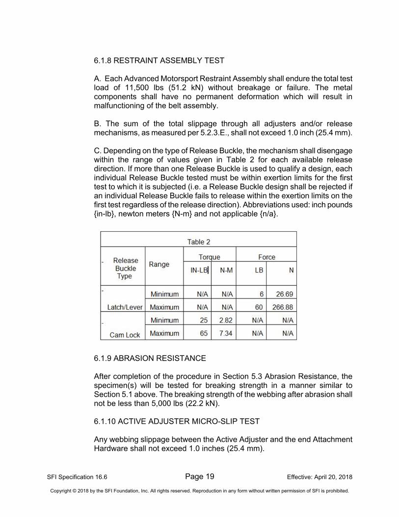
C. Depending on the type of Release Buckle, the mechanism shall disengage within the range of values given in Table 2 for each available release direction. If more than one Release Buckle is used to qualify a design, each individual Release Buckle tested must be within exertion limits for the first test to which it is subjected (i.e. a Release Buckle design shall be rejected if an individual Release Buckle fails to release within the exertion limits on the first test regardless of the release direction). Abbreviations used: inch pounds {in-lb}, newton meters {N-m} and not applicable {n/a}.
6.1.9 ABRASION RESISTANCE After completion of the procedure in Section 5.3 Abrasion Resistance, the specimen(s) will be tested for breaking strength in a manner similar to Section 5.1 above. The breaking strength of the webbing after abrasion shall not be less than 5,000 lbs (22.2 kN).
6.1.10 ACTIVE ADJUSTER MICRO-SLIP TEST Any webbing slippage between the Active Adjuster and the end Attachment Hardware shall not exceed 1.0 inches (25.4 mm).
SFI Specification 16.6 Page 20 Effective: April 20, 2018
Copyright © 2018 by the SFI Foundation, Inc. All rights reserved. Reproduction in any form without written permission of SFI is prohibited.
6.1.11 INDIVIDUAL BELT TENSILE TEST Any webbing slippage at any Adjustment and/or Attachment Hardware as measured per 5.5.3, must not exceed 0.5 inches (12.7 mm). No visible tearing or fractures of the Adjustment and/or Attachment Hardware may be present. No visible tearing, separation or fraying of the webbing material may be present. No visible tearing, separation or failure of the stitching may be present. The permanent deflection of the Seat/chassis end Hardware on the Negative G belt test must not exceed 1.00 inch (25.4 mm) from the test surface (seat surface) to the highest hardware point. 6.1.12 INSTRUCTIONS Any restraint assembly pertaining to this specification shall include Manufacturer’s Installation Instructions with each assembly.
7.0 TEST REPORTS A separate test report, or set of test reports if required, shall be submitted for each product model. If more than one test facility is required to complete all necessary tests, then a separate test report shall be submitted from each one. A test report shall be submitted for each component, if tested separately. The test facility shall assign a unique number to each test report. This number along with the report date and page number shall appear on each page. Each test report shall include:
7.1 RELEVANT INFORMATION
7.1.1 Manufacturer's name, contact name, address and telephone number.
7.1.2 Name, address and telephone number of the test facility.
7.1.3 Name and signature of the responsible test supervisor.
7.1.4 Actual date of the test.
7.1.5 Specification number and effective date.
7.1.6 Product name, description and part number/model number designation.
7.1.7 Component name and description.
SFI Specification 16.6 Page 21 Effective: April 20, 2018
Copyright © 2018 by the SFI Foundation, Inc. All rights reserved. Reproduction in any form without written permission of SFI is prohibited.
7.2 TESTS Each test conducted shall be listed showing the test name, apparatus used, procedure used and test results obtained along with any other appropriate information. 7.3 AUTHENTICATION Test reports shall be authenticated and stamped by a Professional Engineer who is registered in the state in which the testing is conducted. If necessary, SFI may allow an equivalent entity to provide authentication.
8.0 INITIAL DESIGN VALIDATION To receive initial recognition from SFI as a participant in the SFI Specification 16.6 Program, the manufacturer must submit to SFI all information delineated in the Proof of Compliance section. This information shall be provided for each Advanced Motorsport Restraint Assembly part number/model offered by the applicant that is to be included in the program. Any change in design, materials and/or methods of manufacturing not specifically excluded is considered a part number/model change and, therefore, requires initial design validation.
Note: A model certification is based on the successful test results submitted for restraint assemblies with all offered mounting configurations. A restraint assembly variation shall not be considered certified under this part number/model number if it is later produced with a different mounting configuration unless it is also successfully tested.
9.0 PERIODIC REVALIDATION Test reports with successful test results must be submitted to SFI at least once every 24 months following the date of the initial design validation test for each part number/model of Advanced Motorsport Restraint Assembly manufactured by the participant. If multiple test reports are required to obtain all test results, then the earliest test date shall be used to determine when the periodic revalidation reports are due. Also, SFI shall retain the option to conduct random audit reviews. SFI shall purchase the product on a commercial basis and test for compliance to the specification. The submitting manufacturer shall reimburse SFI for all audit costs. 10.0 CERTIFICATION OF COMPLIANCE Upon demonstration of successful compliance with all the requirements of the specification and the self-certification program and upon entering the licensing agreement with SFI, the manufacturer may advertise, present and offer the Advanced Motorsport Restraint Assemblies for sale with the representation that their product meets the SFI Specification
SFI Specification 16.6 Page 22 Effective: April 20, 2018
Copyright © 2018 by the SFI Foundation, Inc. All rights reserved. Reproduction in any form without written permission of SFI is prohibited.
16.6. Continuing certification is contingent upon the following additional considerations: (1) the product shall be resubmitted for testing following any change in design, materials and/or methods of manufacturing not specifically excluded, and (2) periodic revalidation test reports are submitted when due to SFI.
11.0 CONFORMANCE LABELS The SFI conformance label is a label, purchased from SFI. One label shall be sewn or otherwise permanently attached in an acceptable manner to SFI onto each Belt Sub-Assembly of the Advanced Motorsport Restraint Assembly. For Negative G Belt webbing, which is not woven narrow fabric, the SFI conformance label must be attached in a permanent manner which is readily visible and acceptable to SFI. The label issued by SFI is preprinted to indicate the month and year of certification expiration per Paragraph 2.2 of this specification. 12.0 DECERTIFICATION Participating manufacturers are subject to decertification when not in compliance with the requirements of this program or when their products are not in compliance with the requirements of this specification. Decertification will provide SFI the right to effect any and all remedies which are available to SFI in the licensing agreement. 13.0 APPEAL PROCEDURE In the event of decertification, the manufacturer is entitled to an appeal of the decision of SFI. Requests for appeal must be received by SFI no later than thirty days following receipt of the notice of decertification. Appeals of such decisions will be heard at the next meeting of the Board of Directors of SFI. 14.0 STATEMENT OF LIMITATIONS Testing procedures and/or standards contained in this specification are intended for use only as a guide in determining compliance with the minimum performance requirements as defined herein. The granting and assignment of the "This Manufacturer Certifies That This Product Meets SFI Specification 16.6" logo/designation is in no way an endorsement or certification of product performance or reliability by SFI. SFI, its officers, directors and/or members assume no responsibility, legal or otherwise, for failure or malfunctions of a product under this program. 15.0 COSTS All costs involved in this program will be absorbed by the submitting manufacturer.
SFI Specification 16.6 Page 23 Effective: April 20, 2018
Copyright © 2018 by the SFI Foundation, Inc. All rights reserved. Reproduction in any form without written permission of SFI is prohibited.
16.0 COMPLIANCE PERIOD As this specification is revised to reflect changes in technology and/or field conditions, to remain current, participating manufacturers in the SFI Specification 16.6, Advanced Motorsport Restraint Assembly Program must demonstrate full compliance with the requirements of this specification within ninety (90) days of the latest effective date. * Original Issue: December 29, 2014 Reviewed: December 11, 2015 Edited: January 20, 2017 Reviewed: December 8, 2017 Revised: April 20, 2018 Edited: May 9, 2018