Embed Size (px)
Citation preview
SGI® ICE X in D-racks
Site Planning Guide
007-5890-001
COPYRIGHT
© 2012 SGI. All rights reserved; provided portions may be copyright in third parties, as indicated elsewhere herein. No permission is granted to copy, distribute,
or create derivative works from the contents of this electronic documentation in any manner, in whole or in part, without the prior written permission of SGI.
LIMITED RIGHTS LEGEND
The software described in this document is “commercial computer software” provided with restricted rights (except as to included open/free source) as specified
in the FAR 52.227-19 and/or the DFAR 227.7202, or successive sections. Use beyond license provisions is a violation of worldwide intellectual property laws,
treaties and conventions.This document is provided with limited rights as defined in 52.227-14.
The electronic (software) version of this document was developed at private expense; if acquired under an agreement with the USA government or any
contractor thereto, it is acquired as "commercial computer software" subject to the provisions of its applicable license agreement, as specified in (a) 48 CFR
12.212 of the FAR; or, if acquired for Department of Defense units, (b) 48 CFR 227-7202 of the DoD FAR Supplement; or sections succeeding thereto.
Contractor/manufacturer is SGI, 46600 Landing Parkway, Fremont, CA 94538.
TRADEMARKS AND ATTRIBUTIONS
Silicon Graphics, SGI, and the SGI logo, are registered trademarks of Silicon Graphics, Inc., in the United States and/or other countries worldwide.
Aeroquip is a registered trademark of Aeroquip Corporation. ASHRAE is a registered service mark of the American Society of Heating, Refrigerating and
Air-Conditioning Engineers, Inc. Hansen is a trademark Hansen Products Limited (NZ). Intel and Xeon are trademarks or registered trademarks of Intel
Corporation or its subsidiaries in the United States and other countries. All other trademarks mentioned herein are the property of their respective owners.
Record of Revision
Version Description
001 November 2012
Original printing.
007-5890-001 iii
:
iv 007-5890-001
Contents
Contents
1 Site Preparation Overview
Warnings and Cautions . . . . . . . . . . . . . . . . . . . . 2
Pallet Jack Requirements . . . . . . . . . . . . . . . . . . 3
About this Guide. . . . . . . . . . . . . . . . . . . . . . 3
Obtaining Publications . . . . . . . . . . . . . . . . . . . . 3
Reader Comments . . . . . . . . . . . . . . . . . . . . . 4
Physical Location . . . . . . . . . . . . . . . . . . . . . 5
Selecting a Delivery Route . . . . . . . . . . . . . . . . . . 5
Selecting a Final Location . . . . . . . . . . . . . . . . . . 7
Floor Requirements . . . . . . . . . . . . . . . . . . . . . 8
Electrical Requirements . . . . . . . . . . . . . . . . . . . . 9
Voltage Requirements . . . . . . . . . . . . . . . . . . . 9
Power Requirements . . . . . . . . . . . . . . . . . . 10
Grounding Requirements . . . . . . . . . . . . . . . . . 11
Power Factor . . . . . . . . . . . . . . . . . . . . 12
Inrush Current . . . . . . . . . . . . . . . . . . . . 12
Power-line Treatment . . . . . . . . . . . . . . . . . . 13
Total Harmonic Distortion . . . . . . . . . . . . . . . . . 13
Thermal Requirements . . . . . . . . . . . . . . . . . . . 14
Heat Output . . . . . . . . . . . . . . . . . . . . . 14
Air-conditioning Terminology . . . . . . . . . . . . . . . . 14
Calculating Thermal Load . . . . . . . . . . . . . . . . . 15
Water-cooled Rack Requirements . . . . . . . . . . . . . . . 16
Cooling Water Requirements . . . . . . . . . . . . . . . 16
Piping Requirements . . . . . . . . . . . . . . . . . 17
007-5890-001 v
Contents
Cooling Water Supply Requirements . . . . . . . . . . . . . 17
Thermal Gradient . . . . . . . . . . . . . . . . . . . 18
Cooling In Mission-critical Installations . . . . . . . . . . . . . 18
Environmental Requirements . . . . . . . . . . . . . . . . . 19
Electromagnetic Interference . . . . . . . . . . . . . . . . 19
Electrostatic Discharge . . . . . . . . . . . . . . . . . . 19
Vibration. . . . . . . . . . . . . . . . . . . . . . 20
Humidity. . . . . . . . . . . . . . . . . . . . . . 20
Humidity Gradient . . . . . . . . . . . . . . . . . . . 20
Ergonomic Requirements . . . . . . . . . . . . . . . . . . 21
Acoustics . . . . . . . . . . . . . . . . . . . . . 21
Local Regulations . . . . . . . . . . . . . . . . . . . . 22
Planning for the Future . . . . . . . . . . . . . . . . . . . 22
2 Components
Server Racks . . . . . . . . . . . . . . . . . . . . . . 24
Blade Enclosure Pair . . . . . . . . . . . . . . . . . . . . 26
Power Supplies . . . . . . . . . . . . . . . . . . . . 28
Cooling . . . . . . . . . . . . . . . . . . . . . . 28
I/O Expansion Racks . . . . . . . . . . . . . . . . . . . . 29
Trellis System . . . . . . . . . . . . . . . . . . . . . 30
3 Specifications
Shipping Container Specifications . . . . . . . . . . . . . . . . 32
Rack Dimensions . . . . . . . . . . . . . . . . . . . . . 34
Rack Spacing . . . . . . . . . . . . . . . . . . . . . . 38
Rack Bonding Straps . . . . . . . . . . . . . . . . . . 39
System Specifications . . . . . . . . . . . . . . . . . . . 41
Air-cooled Environmental Specifications . . . . . . . . . . . . . . 44
Water-cooled Environmental Specifications . . . . . . . . . . . . . . 45
Shock and Vibration . . . . . . . . . . . . . . . . . . . . 46
4 Layouts and Clearances
General Recommendations . . . . . . . . . . . . . . . . . . 47
Air-cooled Rack Layout . . . . . . . . . . . . . . . . . . . 48
vi 007-5890-001
Contents
Water-cooled Rack Layout . . . . . . . . . . . . . . . . . . 50
Service Clearance Requirements . . . . . . . . . . . . . . . . 52
Seismic Tiedowns . . . . . . . . . . . . . . . . . . . . 52
5 Site Planning Checklist
007-5890-001 vii
Contents
viii 007-5890-001
Figures
Figures
Figure 2-1 SGI ICE X System - Front View . . . . . . . . . . . 24
Figure 2-2 SGI ICE X Air-cooled and Water-Cooled Systems - Rear View. . . 25
Figure 2-3 Blade Enclosure Pair - Front . . . . . . . . . . . . 26
Figure 2-4 Blade Enclosure Pair Component Numbering . . . . . . . 27
Figure 2-5 IRU Blowers - Rear . . . . . . . . . . . . . . 28
Figure 2-6 I/O Expansion Rack . . . . . . . . . . . . . . 29
Figure 2-7 SGI ICE X D-racks with Trellis System . . . . . . . . . 30
Figure 3-1 Wooden Crate Shipping Container Dimensions . . . . . . . 32
Figure 3-2 Cardboard Crate Shipping Container Dimensions . . . . . . 33
Figure 3-3 SGI ICE X Compute Rack Dimensions (Air-cooled Rack) . . . . 34
Figure 3-4 Rack Lift Opening in Shipping Configuration
(Air-cooled SGI ICE X Compute Rack) . . . . . . . . . 35
Figure 3-5 SGI ICE X Compute Rack Dimensions (Water-cooled Rack) . . . 36
Figure 3-6 Rack Lift Opening in Shipping Configuration
(Water-cooled SGI ICE X Compute Rack) . . . . . . . . 37
Figure 3-7 Rack Spacing . . . . . . . . . . . . . . . . 38
Figure 3-8 Rack Bonding Straps – Top of Rack . . . . . . . . . . 39
Figure 3-9 Rack Bonding Strap – Bottom of Rack . . . . . . . . . 40
Figure 4-1 Single Air-cooled Rack Floor Layout (Shown on 24-in by 24-in Grid) . 48
Figure 4-2 Air-cooled Rack Floor Layout - Four Racks
(Shown on 24-in by 24-in Grid) . . . . . . . . . . . 49
Figure 4-3 Single Water-cooled Rack Floor Layout
(Shown on 24-in by 24-in Grid) . . . . . . . . . . . 50
Figure 4-4 Water-cooled Rack Floor Layout - Four Racks
(Shown on 24-in by 24-in Grid) . . . . . . . . . . . 51
Figure 4-5 Service Clearance Requirements (Shown on 24-in by 24-in Grid) . . 52
Figure 4-6 Seismic Tiedown Locations . . . . . . . . . . . . 53
007-5890-001 ix
Figures
x 007-5890-001
Tables
Tables
Table 1-1 Floor Load Terminology . . . . . . . . . . . . 8
Table 1-2 Electrical Service Requirements . . . . . . . . . . 9
Table 1-3 Cooling Water Specifications (Example) . . . . . . 16
Table 3-1 SGI ICE X System Specifications . . . . . . . . 41
Table 3-2 Air-cooled System Environmental Requirements . . . . 44
Table 3-3 Water-cooled System Environmental Requirements. . . . 45
Table 5-1 Site Planning Checklist . . . . . . . . . . . 55
Table 5-2 Water-cooled Option Site Planning Checklist . . . . . 57
007-5890-001 xi
Tables
xii 007-5890-001
Chapter 1
1. Site Preparation Overview
This document provides information that helps management and facilities personnel prepare for
an SGI ICE X server in D-rack(s) installation. It includes general site planning concepts as well
as specific site requirements that you may use as a guide during the site planning and preparation
process.
SGI site planning representatives are available in the United States of America for site planning
consultation; contact a site planning representative by telephone in the USA at +1 715 726 2820;
by fax at +1 715 726 2969; or by e-mail at [email protected].
Contact your account manager to discuss your site planning, preparation, and installation plans
and to obtain configuration information for any system.
Use the following steps as a planning guide for your system installation:
1. Identify the space, power, and environmental requirements for the system.
2. Select a location for the system and identify any necessary modifications.
3. Prepare the site according to the guidelines in this publication. You may use the site planning
checklist in Chapter 5 on 55 of this document as a guide.
007-5890-001 1
1: Site Preparation Overview
Warnings and Cautions
Read the following safety and warnings and cautions before you receive your SGI ICE X server.
Warning: The maximum weight of a single water-cooled SGI ICE X rack is:
- 2,532 lb (1,148 kg) when in shipping configuration
- 2,062 lb (935 kg) when cabled and operating
This system must be moved and installed by trained SGI personnel or authorized agents
only. Make sure that the weight of the rack and pallet jack does not exceed the maximum
safe floor load limits at your location. Failure to do so may result in property damage,
serious injury, or death.
Warning: The maximum weight of an SGI ICE X rack is 2,532 lb (1,148 kg). This system
must be moved and installed by trained SGI personnel or authorized agents to ensure that
the rolling weight of the rack and the pallet jack does not exceed the maximum safe floor
load limits at your location. Failure to do so may result in property damage, serious injury
or death.
Warning: The maximum operating weight of a single water-cooled SGI ICE X rack while
operating is 2,062 lb. (935 kg). Make sure that the weight of the entire system does not exceed
the maximum safe floor load capacity at your location. Failure to do so may result in
property damage, serious injury, or death.
Caution: To avoid an impact related injury, keep the water-cooled doors closed when working
near (or beneath) the rear of the rack.
Caution: To reduce the likelihood of exposure to personal injury or property damage, SGI
recommends that you use a 27-in wide pallet jack to move the system racks or crates. Use the
pallet jack to lift the rack only as far as needed to clear obstacles.
!
!
!
!
!
2 007-5890-001
About this Guide
Pallet Jack Requirements
Two people are required to push or pull the rack, ideally a third to inspect and clear the path of any
obstacles. When possible, use a pallet jack to move crates or racks, especially up/down ramps.
When a pallet jack is not available:
• Push rather than pull the system racks. It is easier and safer to push than to pull. You can use
your body weight to assist when pushing.
• Keep close to the load and lock your arms. Try not to lean over and keep your back in its
natural arches.
• Use both hands. Racks are easier to push and control using both hands.
About this Guide
This guide is intended for people who are responsible for physical site planning and preparation.
By planning for your SGI ICE X system installation, you will have the opportunity to make
adjustments to your site and order any additional facility equipment, thereby reducing the time
required to install your system.
Obtaining Publications
To obtain SGI documentation, go to the SGI Technical Publications Library at http://docs.sgi.com.
007-5890-001 3
1: Site Preparation Overview
Reader Comments
If you have comments about the technical accuracy, content, or organization of this document,
please tell us. Be sure to include the title and document number of the manual with your
comments. (Online, the document number is located in the front matter of the manual. In printed
manuals, the document number is located on the back cover.)
You can contact us in any of the following ways:
• Send e-mail to [email protected]
• Contact your customer service representative and ask that an incident be filed in the SGI
incident tracking system.
• Send mail to the following address:
SGI Site Planning
890 Technology Way
Chippewa Falls, WI 54729-0078
USA
4 007-5890-001
Physical Location
Physical Location
This section addresses the issues that you need to consider when you select a physical location for
a new system.
Selecting a Delivery Route
Warning: The maximum weight of a single water-cooled SGI ICE X rack is:
- 2,532 lb (1,148 kg) when in shipping configuration
- 2,062 lb (935 kg) when cabled and operating
This system must be moved and installed by trained SGI personnel or authorized agents
only. Make sure that the weight of the rack and pallet jack does not exceed the maximum
safe floor load limits at your location. Failure to do so may result in property damage,
serious injury, or death.
To ensure that the system can be delivered to the planned location, answer the following questions
before you plan a delivery route for the new system:
• Will the shipping crate fit through doorways and hallways and on elevators?
In addition to measuring the width of the hallways along the planned delivery route, measure
corners where the system might get stuck, the width and height of doorways and elevators,
and other areas that may cause problems. Table 3-1 lists the relevant system dimensions.
• SGI recommends that you use a pallet jack to position the rack as close as possible to its
final destination. If the shipping crate cannot be transported to the final destination, can you
unpack the system somewhere else?
Often it is possible to unpack the system in a hallway or on a loading dock, and then roll the
system to its final destination.
!
007-5890-001 5
1: Site Preparation Overview
• Is the floor strong enough to support the weight of the system?
Determine the weight of each rack and verify that the floor along the delivery route can
safely support the weight. Refer to Table 3-1 for the maximum weight per system rack.
Refer to “Floor Requirements” on page 8 for information about floor loading.
Note: It may be necessary to depopulate IRUs in the rack to reduce the weight of the system.
You may also consider using floor plates to disperse the weight of the system during transport
to its final location.
• Is the elevator capable of lifting the system?
If the intended delivery route includes an elevator, check its weight capacity and size against
the system specifications listed in Table 3-1. The use of freight blankets can reduce damage
to the elevator or the system.
• Are there any steep angles, bumps, changes in level, or thick carpeting along the delivery
route?
Large systems are typically equipped with casters. However, the casters are designed to roll
easily only on relatively smooth, level surfaces. Ramps, sliding door channels, rough
flooring, and even thick carpeting may present difficulty. If in doubt, arrange for additional
assistance. The maximum access incline should not exceed 10 degrees (height:length = 1:6).
• Did you ensure that the leveling pads are fully retracted?
Some systems have screw-in leveling pads. If you move the system with these feet extended,
severe damage to the chassis can occur. These feet sometimes unscrew during shipment.
Before you unpack or move a system, ensure that the leveling pads are fully retracted.
6 007-5890-001
Physical Location
Selecting a Final Location
Consider the following issues when you select a final location for the system:
• Will the system fit in its intended location?
Carefully calculate the total system dimensions to ensure that it will fit in its intended final
location.
• Does the intended system location provide adequate access space for maintenance?
• Even if the system will fit in its intended final location, you must have room to maintain it.
Ensure that you have enough room to open the doors, remove boards, and accomplish other
routine tasks. Table 3-1 lists the relevant system dimensions. Chapter 4, “Layouts and
Clearances” shows the typical computer room floor space requirements. As a general rule,
SGI ICE X systems require 48-in of clearance from the front and rear of the rack. Side
access to the rack is not required for service.
• Is the intended location subject to flooding, extremes of humidity or temperature, or any
other factor that would make it inappropriate for sensitive electronic equipment?
The air temperature should not be too high and should not fluctuate dramatically, air should
circulate freely and be relatively dust-free, and the system should not be exposed to any
caustic or corrosive chemicals or vapors. Refer to Table 3-1 for computer room air
temperature requirements.
• Will the system interfere with normal traffic through aisles, hallways, or entrance ways in
the intended location?
• Will the intended location enable you to conveniently perform routine operations, such as
loading and unloading media, attaching cables, and so on?
• Is the floor of the intended final location strong enough to support the weight of the system
and any future expansions? Large systems should be installed in computer rooms with raised
floors. Pay particular attention to floor loading and weight distribution in this case.
Floor-loading specifications are typically calculated by averaging the total chassis weight
that is distributed over the entire footprint of the chassis. Because the chassis sits on four
casters or four leveling pads, the load at each of these four points is greater. Refer to “Floor
Requirements” on page 8 for more information about floor loading.
• Does the intended location of the system allow for future expansion plans?
• Is there the potential for seismic activity in your area? Refer to “Seismic Tiedowns” in
Chapter 4.
007-5890-001 7
1: Site Preparation Overview
Floor Requirements
The total system weight on a facilities floor and the building structure must be considered. The
computer room floor, as well as any floors along the delivery route, must be able to support the
total weight of the computer system when installed as well as the weight of individual racks as
they are moved into position.
Note: It may be necessary to depopulate IRUs in the rack to reduce the weight of the system. You
may also consider using floor plates to disperse the weight of the system during transport to its
final location.
Any floor system should be evaluated and verified by a structural engineer or appropriate floor
consultant. They should use the manufacture’s specifications to determine what floor loading
characteristics the floor should have to support this computer equipment.
SGI recommends a bolted stringer understructure raised floor. Raised floor systems provide space
to route power and signal cables as well as room for cooling water pipes if needed. The height of
the raised floor should be at least 24-in (61 cm).
Table 1-1 lists some commonly used floor load terminology.
Table 1-1 Floor Load Terminology
Live Load The load that the floor can safely support. Lbs/Sq Ft (KG/Sq m)
Concentrated Load The load that a floor panel can support on one square inch at its weakest point,
typically the center of the panel, without the panel deflecting more than a
predetermined amount.
Ultimate Load The maximum load per floor panel that the floor system can support without failure
such as bending or braking.
Rolling Load The load a floor panel can support without failure when a wheel or castor of a
specified diameter and width is rolled across the panel.
Average Floor Load Determined by dividing the total equipment weight by the area of the footprint of
equipment expressed in Lbs/Sq Ft (KG/Sq M). Average floor loading is useful for
determining floor loading at the building level, such as the area of solid floor or
raised floor panels covered by the systems footprint.
8 007-5890-001
Electrical Requirements
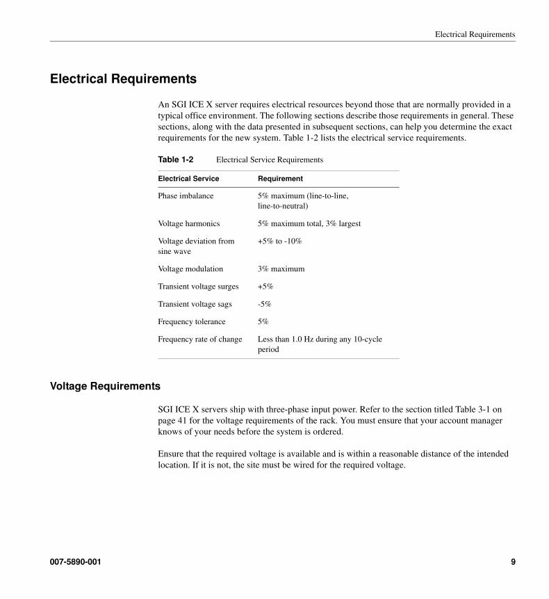
Electrical Requirements
An SGI ICE X server requires electrical resources beyond those that are normally provided in a
typical office environment. The following sections describe those requirements in general. These
sections, along with the data presented in subsequent sections, can help you determine the exact
requirements for the new system. Table 1-2 lists the electrical service requirements.
Voltage Requirements
SGI ICE X servers ship with three-phase input power. Refer to the section titled Table 3-1 on
page 41 for the voltage requirements of the rack. You must ensure that your account manager
knows of your needs before the system is ordered.
Ensure that the required voltage is available and is within a reasonable distance of the intended
location. If it is not, the site must be wired for the required voltage.
Table 1-2 Electrical Service Requirements
Electrical Service Requirement
Phase imbalance 5% maximum (line-to-line,
line-to-neutral)
Voltage harmonics 5% maximum total, 3% largest
Voltage deviation from
sine wave
+5% to -10%
Voltage modulation 3% maximum
Transient voltage surges +5%
Transient voltage sags -5%
Frequency tolerance 5%
Frequency rate of change Less than 1.0 Hz during any 10-cycle
period
007-5890-001 9
1: Site Preparation Overview
Power Requirements
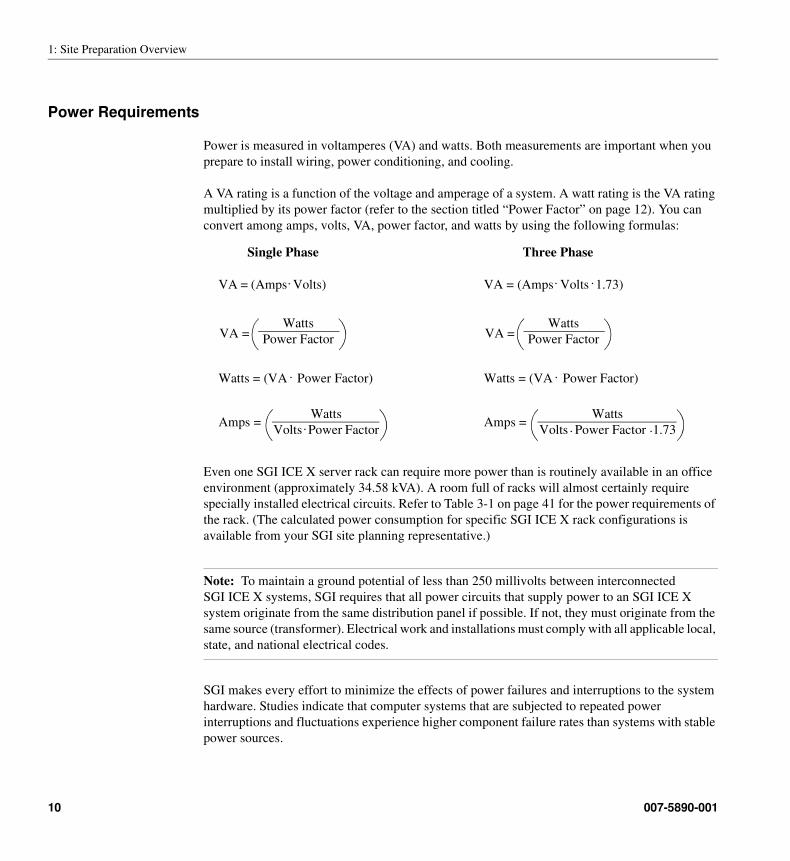
Power is measured in voltamperes (VA) and watts. Both measurements are important when you
prepare to install wiring, power conditioning, and cooling.
A VA rating is a function of the voltage and amperage of a system. A watt rating is the VA rating
multiplied by its power factor (refer to the section titled “Power Factor” on page 12). You can
convert among amps, volts, VA, power factor, and watts by using the following formulas:
Even one SGI ICE X server rack can require more power than is routinely available in an office
environment (approximately 34.58 kVA). A room full of racks will almost certainly require
specially installed electrical circuits. Refer to Table 3-1 on page 41 for the power requirements of
the rack. (The calculated power consumption for specific SGI ICE X rack configurations is
available from your SGI site planning representative.)
Note: To maintain a ground potential of less than 250 millivolts between interconnected
SGI ICE X systems, SGI requires that all power circuits that supply power to an SGI ICE X
system originate from the same distribution panel if possible. If not, they must originate from the
same source (transformer). Electrical work and installations must comply with all applicable local,
state, and national electrical codes.
SGI makes every effort to minimize the effects of power failures and interruptions to the system
hardware. Studies indicate that computer systems that are subjected to repeated power
interruptions and fluctuations experience higher component failure rates than systems with stable
power sources.
Watts
Volts Power Factor.Amps =
Watts = (VA Power Factor)
VA = (Amps Volts).
VA =Watts
Power Factor
. Watts = (VA Power Factor)
Watts
Volts Power Factor 1.73
VA = (Amps Volts 1.73).
VA =Watts
Power Factor
Amps =
.
. .
Single Phase Three Phase
.
10 007-5890-001
Electrical Requirements
SGI encourages you to install a stable power source, such as an uninterruptible power system
(UPS), to minimize component failures. Each SGI ICE X system and each piece of support
equipment requires its own customer-supplied receptacles. If you have difficulty obtaining the
correct receptacles as listed in Table 3-1, please contact your account manager.
Note: The wattages listed in this guide are the system maximums. While most systems may never
draw the maximum rated wattage, SGI recommends that you install wiring that is capable of
supporting the system’s maximum potential wattage.
If, after you add up the power requirements of all the devices in the room, you find that the total
is close to the limit that the existing wiring can support, you should install additional power
circuits to support the systems.
Grounding Requirements
• Ensure that the ground has sufficiently low impedance in order to limit the voltage to ground
and to facilitate the operation of protective devices in the electrical circuit.
• Ensure that all grounds entering the room are interconnected somewhere within the building
to provide a common ground potential. This includes any separate power sources, lighting,
convenience outlets, and other grounded objects such as building steel, plumbing, and
ductwork. Refer to the IEEE Emerald Book: IEEE Recommended Practices for Powering
and Grounding Electronic Equipment and the National Electric Code (NEC) for power,
grounding, and life safety issues.
Caution: Any difference in ground potential greater than 250 millivolts between two racks
can cause severe equipment damage.
• To maintain your entire SGI ICE X server at the same electrical potential, all multiple-rack
systems must be bolted together. Refer to “Rack Bonding Straps” on page 39 for more
information.
!
007-5890-001 11
1: Site Preparation Overview
Power Factor
Power factor is a number between 0 and 1 that represents the ratio of the total power in watts to
the total volt-amperage input. A system with a power factor of one (sometimes called “unity”) is
making full use of the energy that it draws. A system with a power factor of 0.75 is effectively
using only three-quarters of the energy that it draws.
SGI ICE X servers are power-factor corrected and thus have a power factor very close to 1. Some
peripherals do not have this correction built in.
Caution: Ensure that you consider the power factor of the system when you select an
uninterruptible power supply (UPS).
Inrush Current
Inrush current is the peak current that flows into a power supply as AC power is applied. The
inrush current is usually much higher than the nominal current. This temporary increase is due to
the charging of the input filter capacitors in the power supply and is limited only by the input
impedance of the power supply and the wiring that supplies power to the system.
The inrush current often far exceeds the rating of the electrical outlet to which the system is
connected. If the system is connected directly to “wall power” (that is, it is not on a UPS or a
standby power system [SPS]), this is typically not a problem. The peak inrush current lasts for only
a part of one AC cycle (less than 1/60 of a second). This is not long enough to damage wiring and,
in most cases, will not trip a circuit breaker (depending on the delay curves of the circuit breaker).
It is very important that you consider the inrush current of the system when you select a UPS or
SPS. Unlike power-company lines, these power-conditioning devices may not be able to supply
the current that is required during power-on, even if they are sized appropriately for nominal
current loads. For more information, refer to the following “Power-line Treatment” section.
It is possible for the inrush current drawn by a device to cause a slight drop in the line voltage.
Although it is very brief, this drop can, in unusual situations, be enough to cause problems in other
devices on the same line.
Inrush current is a characteristic of the power supplies in a system. The inrush current values apply
whether the system is heavily or lightly loaded. Therefore, although a lightly loaded system may
draw less power while it is running, it may still draw a very large inrush current.
SGI ICE X servers typically have low inrush characteristics.
!
12 007-5890-001
Electrical Requirements
Power-line Treatment
Power-line treatment may be required if the site has unstable power that results in problems such
as fluctuating voltage, transients, surges and spikes, and noise. Common causes of unreliable
power are old wiring; load-switching equipment, such as welding and plating devices; and
variable-speed motors or motors that start and stop frequently.
A variety of devices are available to improve the quality of a power line, including:
• Line conditioners
• Line regulators
• Isolation transformers
• UPSs
Ask your SGI representative for more information about power solutions.
Total Harmonic Distortion
Table 3-1 lists total harmonic distortion (THD). Total harmonic distortion is a measure of the
extent to which a waveform is distorted by harmonic content. This rating indicates how much the
power supply in the system affects the quality of power delivered to other systems that are
supplied by the same transformer.
Note: While the term total harmonic distortion can be applied to either voltage or current, all of
the numbers listed in this guide apply to current.
007-5890-001 13
1: Site Preparation Overview
Thermal Requirements
It is important that the SGI ICE X servers be maintained within their rated thermal range.
Refer to Table 3-1 on page 41 for the temperature ranges for each rack, both operating and
nonoperating as well as the recommended operating ambient temperature. Typically, the upper
limit of the temperature range is more likely to become a problem than the lower limit.
Heat Output
All of the systems that this guide describes have a maximum rated operating temperature.
Exceeding this temperature greatly increases the rate of hardware failure and, in many cases,
causes the system to shut itself down.
All of the power consumed by a computer system must exist as some form of energy. For
air-cooled systems, this energy exists in the form of heat in the surrounding air. Every watt drawn
by a system is eventually dissipated as heat. This heat tends to raise the temperature of the air in
the room that houses the system. Therefore, some method is needed to keep the temperature within
the required range. The typical method is to install additional process cooling capacity or to order
a system with water-cooled racks.
The maximum heat dissipation-to-air per rack is listed in Chapter 3, “Specifications”.
Air-conditioning Terminology
Air-conditioning capacity is generally measured in Btu/hr, tons, or kilocalories (kcal). A Btu, or
British thermal unit, is the amount of energy needed to raise the temperature of one pound of water
by one degree Fahrenheit at a constant pressure of one atmosphere. One ton of air conditioning
removes 12,000 Btu of heat energy per hour.
The more systems that are installed in a given area, the larger the air-conditioning capacity that is
required. It is important to calculate the total thermal load of the systems that you will be installing
and determine whether the existing air-conditioning system can handle the additional load. If not,
you must provide additional cooling capacity.
14 007-5890-001
Thermal Requirements
Calculating Thermal Load
You can calculate the thermal load as follows:
1. Add the wattages of all the items in the room.
2. Calculate Btu/hour by multiplying the total wattage by 3.41.
3. Calculate the kcal/hour by multiplying the total wattage by 3.23.
4. Calculate the tons of air-conditioning load by dividing Btu/hr by 12,000.
1 kBtu/hr = 1000 Btu/hr
12,000 Btu/hr = 1 ton of air-conditioning load
The calculations above yield results that represent the maximum thermal output of the equipment.
These calculations and the heat-dissipation numbers that Table 3-1 on page 41 lists are based on
maximum rated wattage.
The thermal figures quoted in this guide are likely to be worst-case figures.
Some sources quote a “typical” thermal output for a system, which may be significantly less than
the numbers listed in this guide. Selecting an air-conditioning capacity that accommodates the
“worst-case” thermal output, however, helps to minimize system problems later.
When you calculate the air-conditioning capacity that is required, be sure to include the heat load
from computer equipment that is already installed at the site, noncomputer equipment that is
already installed at the site, and the computer equipment that is being added. Also remember to
include noncomputer equipment that is already installed or will be installed, and other factors such
as solar gain, outside ambient air temperatures, and the number of people who work in the room.
007-5890-001 15
1: Site Preparation Overview
Water-cooled Rack Requirements
If water-cooled SGI D-racks will be used to provide proper cooling at your site, the following
requirements must be met:
• “Cooling Water Requirements” on page 16
• “Piping Requirements” on page 17
• “Cooling Water Supply Requirements” on page 17
Cooling Water Requirements
Each water-cooled rack requires a customer-supplied source of clean cooling water. The system
will operate on cooling water supply temperatures from 45 °F (7 °C) to 60 °F (15.5 °C). The
actual heat rejection to water, water flow rate, and pressure drop values depend on the temperature
of the water used.
Caution: Water flow and pressure drop values will differ for treated water (antifreeze, corrosion
inhibitors, etc.) depending on the percentage (maximum 30% by volume) of treatment in the
solution. Water flow and pressure drop values will also differ with the temperature and pressure
of the water supply. Water pressure must be limited to 100 psig (690 kPA) maximum.
Example:
The following example values are based on 100% water at a supply temperature of 50 °F (10 °C).
This example assumes that 95% of the heat load is rejected to water and 5% to the computer room
air. Anticipated water-temperature increase across the coil is 23 °F (12.8 °C).
Table 1-3 Cooling Water Specifications (Example)
Heat Rejection to Water
(based on a rack at
30.55 kW) Water Flow Rate Pressure Drop
kBTU/hour Tons gpm m3/hour psi kPA
Each Rack 99 8.25 8 gpm 1.82 17 117
!
16 007-5890-001
Thermal Requirements
Piping Requirements
Water piping must be installed under the raised floor within 4 ft. (1.2 m) of the rear of each
compute rack. SGI supplies flexible hoses with female quick-disconnect couplings to connect the
water-cooled coil to the facility piping connectors. Each water-cooled rack requires one supply
and one return pipe connection. It is the customer’s responsibility to supply one of the following
types of male quick-disconnect nipples:
• Parker - Part Number BH6-61
• Aeroquip - Part number FD45-1086-12-12
• Hansen - Part number B6-K31
SGI also recommends that you:
• Place isolation valves (ball-valves or butterfly valves) near the quick-disconnect nipples
• Insulate the chilled-water supply and chilled-water return piping under the raised-floor to
minimize condensation
• Install a condensate drain/pipe to provide connection to an SGI supplied 6 ft (1.8 m) long,
1/2 inch (12.7 mm) outside diameter, and 3/8 inch (9.5 mm) inside diameter flexible nylon
drain hose from each rack.
You must supply one 1/2-inch push-to-connect type fitting [Parker P/N W68PL-8-8 or
equivalent} connection point within 4 ft (1.2 m) of each associated rack floor cutout.
Cooling Water Supply Requirements
The water-cooled coils can be supplied with water ranging in temperature from 45 to 60 °F (7.2
to 15.6 °C); however, water temperatures cooler than 60 °F (15.6 °C) could cause condensate to
form on the hoses and manifolds.
The customer may treat the cooling water with glycol or corrosion inhibitors up to a maximum of
30%. Water pressure must be limited to 100 psig (690 kPA) maximum.
Based on pure cooling water supplied at 60 ºF (15.6 ºC), each water-cooled rack could require up
to 12 gpm (2.72m3/hr). SGI will provide rates based on you specific configuration. The
corresponding cooling water pressure drop for the (coil + hoses + mated quick-disconnect fittings)
shall be less than 30 psig (207 kPa). These flow and pressure drop values are based on analytical
modeling of expected coil performance.
007-5890-001 17
1: Site Preparation Overview
Thermal Gradient
Table 3-1 on page 41 includes a maximum thermal gradient for each system. The thermal gradient
is the rate at which the temperature changes, which is typically expressed in degrees per hour.
Temperature changes that are more rapid than the given rate can damage some of the components
in the system.
Unless otherwise indicated, the thermal gradients listed apply whether or not the system is
operating.
Cooling In Mission-critical Installations
In mission-critical installations, it is important to consider what would happen if an air conditioner
or chiller failed. Complete consideration of this topic is beyond the scope of this guide; however,
consider the following questions:
• Should the site have multiple air-conditioning or chiller units, each capable of maintaining a
safe temperature?
• If an air conditioner or chiller fails, how long can the systems run before they get too warm
and must be shut off?
• Can the air conditioner or chiller be repaired before the systems get too warm?
18 007-5890-001
Environmental Requirements
Environmental Requirements
Electromagnetic interference (EMI), electrostatic discharge (ESD), vibration, and humidity can
cause problems for computer systems.
Electromagnetic Interference
Electromagnetic interference (EMI) is caused by malfunctioning, incorrectly manufactured, or
incorrectly installed devices that radiate electrical signals. Common sources of EMI include
electronic, telephone, and communications equipment. EMI transmissions can be conducted or
emitted.
Use properly shielded connectors and cables throughout the site.
Caution: Failure to use shielded cables where appropriate may violate FCC regulations and void
the manufacturer’s warranty.
Electrostatic Discharge
SGI designs and tests its products to ensure that they resist the effects of electrostatic discharge
(ESD). However, it is still possible for ESD to cause problems that range from data errors and
lockups to permanent component damage. To protect the systems from ESD, follow these
precautions:
• Minimize the use of carpeting at computer locations
(or consider special static-reducing carpet).
• Ensure that all electronic devices are properly grounded.
• Keep chassis doors and access panels closed while the system is operating.
• Fasten all screws, thumbnail-fasteners, and slide locks securely.
• Use a grounded static wrist strap whenever you work with the chassis or components.
• Use antistatic packing material for storage and transportation.
• Clear the site of all devices that create static electricity or provide possible sources of EMI.
!
007-5890-001 19
1: Site Preparation Overview
Vibration
The SGI ICE X server is designed for typical computer room environments; it requires no special
modifications or protection. If you plan to install a system at an industrial site, ensure that
vibration does not exceed the limits in Table 3-1 on page 41.
Humidity
Table 3-1 on page 41 lists the maximum humidity levels for each rack, both operating and
nonoperating. Exposure to humidity levels above the rated maximums and/or exposure to
condensation can damage equipment.
Humidity Gradient
Table 3-1 on page 41 lists the maximum humidity gradient for the system. The humidity gradient
is the rate at which the humidity changes, which is typically expressed in percent relative humidity
per hour. Humidity changes that are more rapid than the given rate can damage some of the
components in the system. Unless otherwise indicated, the humidity gradients that are listed apply
whether or not the system is operating.
20 007-5890-001
Ergonomic Requirements
Ergonomic Requirements
When you select a physical location, pay attention to ergonomic considerations. The location of a
system often restricts the location of the devices that attach to it, such as monitors, keyboards, and
so on. Decisions that are made during the installation process can affect workers much later.
In addition to attached devices, consider other issues such as noise, temperature, air quality, and
so on, some of which may be affected by the addition of the new system.
Acoustics
The acoustic measurement that Table 3-1 on page 41 lists is approximate. Acoustic values depend
on many factors that are outside the control of the manufacturer. Room characteristics such as
carpeting and wall coverings affect the noise levels at an installation. The acoustic measurement
provided in this document is in dBa (decibels absolute) rather than dB (decibels). This is a
measurement of weighted absolute noise power, and it includes frequency corrections.
If a site exceeds desirable noise levels, try these remedies:
• Reduce the quantity of flat reflective surfaces, such as glass, tile, or metal.
• Add sound-absorbing wall coverings, drapes, and ceiling tiles.
• Add sound baffles in critical locations (without blocking airflow).
• Modify the office space to separate the operators from the hardware.
007-5890-001 21
1: Site Preparation Overview
Local Regulations
Before system installation, become familiar with any applicable local regulations. Because these
vary dramatically by country and state, it is difficult for SGI to provide a complete list of such
regulations. These regulations, however, might involve:
• Power
• Emissions
• Safety issues
• Ergonomic and health issues
• Telecommunications
I you have suggestions about obtaining the local regulations, please ask your SGI representative
for assistance.
Planning for the Future
Even if the existing infrastructure can handle the immediate site needs, consider the future plans.
It is much easier to provide enough space, power, air-conditioning capacity, chilled water capacity
and other resources in advance, rather than to add them later.
22 007-5890-001
Chapter 2
2. Components
An SGI ICE X system is an integrated compute environment that can scale to thousands of Intel
processor cores, terabytes (TBs) of memory, and petabytes (PBs) of storage.
The standard cooling method for SGI ICE X systems in D-rack(s) is blower-driven air cooling.
Each blower enclosure has six blowers that are mounted at the rear of the rack (up to a total of 24
blowers per rack).
Optional supplemental water cooling is available for cases where conventional computer room air
cooling is not adequate. Water-cooled coils are mounted to the rear of the rack. Hot air is exhausted
through each cooling coil, which transfers the heat from the air prior to entering the computer
room. Refer to Table 3-1 on page 41 for the water-cooled option facilities requirements.
Note: Contact [email protected] for specific power and cooling specifications for your system
configuration to determine if your facility will require the water-cooled option.
007-5890-001 23
2: Components
Server Racks
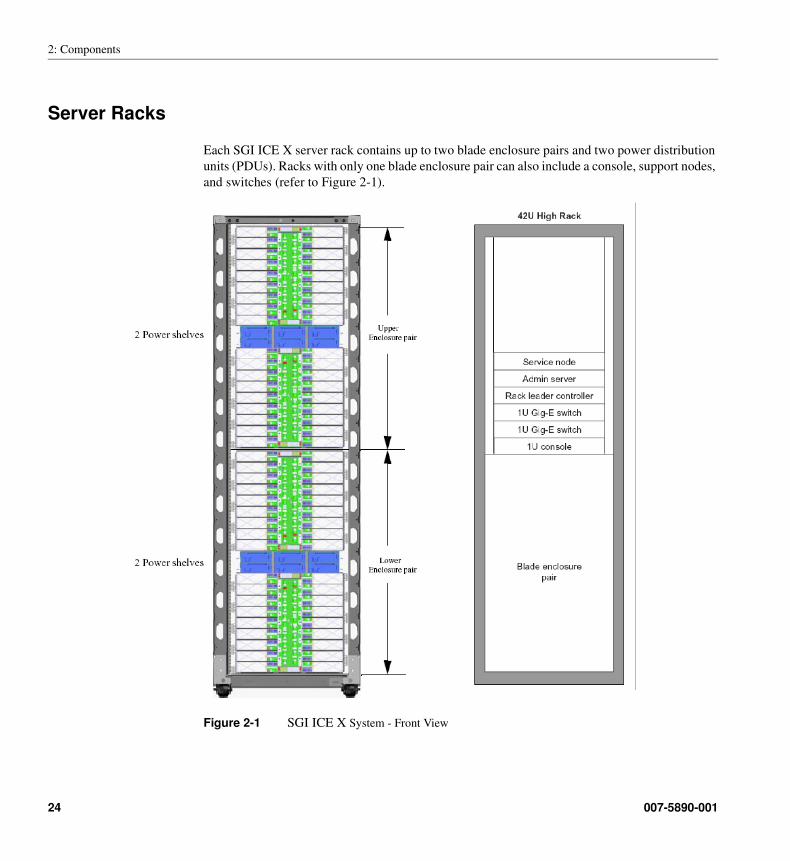
Each SGI ICE X server rack contains up to two blade enclosure pairs and two power distribution
units (PDUs). Racks with only one blade enclosure pair can also include a console, support nodes,
and switches (refer to Figure 2-1).
Figure 2-1 SGI ICE X System - Front View
24 007-5890-001
Server Racks
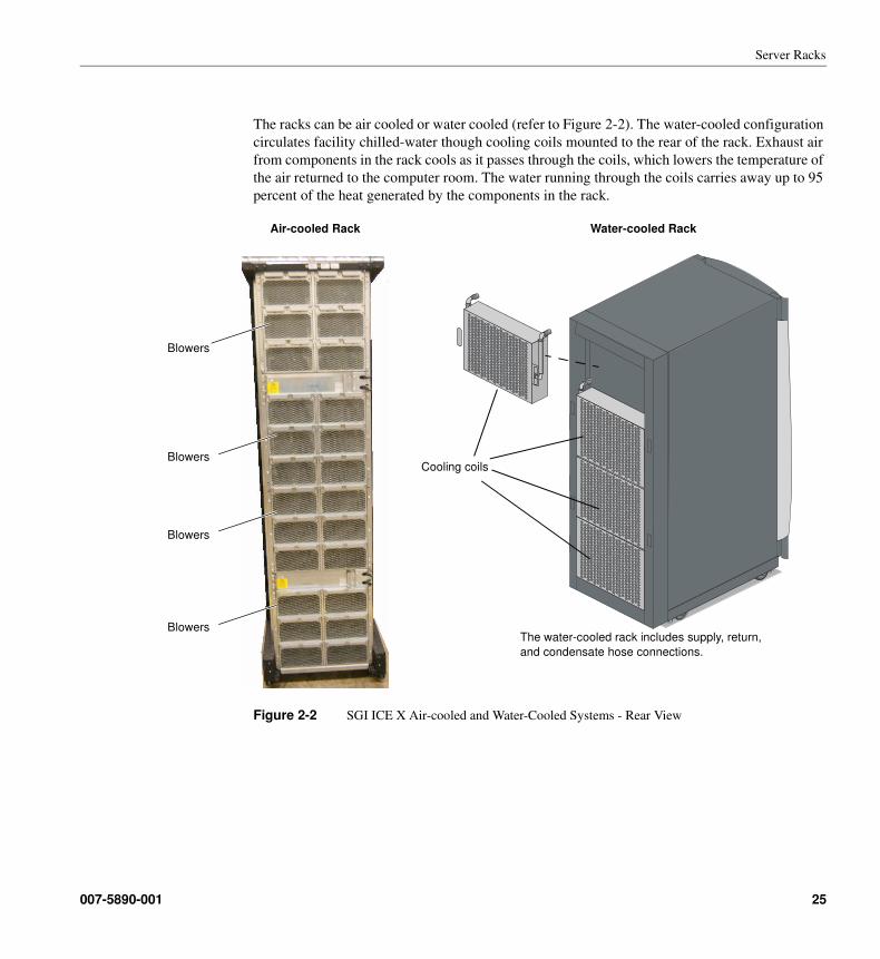
The racks can be air cooled or water cooled (refer to Figure 2-2). The water-cooled configuration
circulates facility chilled-water though cooling coils mounted to the rear of the rack. Exhaust air
from components in the rack cools as it passes through the coils, which lowers the temperature of
the air returned to the computer room. The water running through the coils carries away up to 95
percent of the heat generated by the components in the rack.
Figure 2-2 SGI ICE X Air-cooled and Water-Cooled Systems - Rear View
Cooling coils
The water-cooled rack includes supply, return,
and condensate hose connections.
Air-cooled Rack Water-cooled Rack
Blowers
Blowers
Blowers
Blowers
007-5890-001 25
2: Components
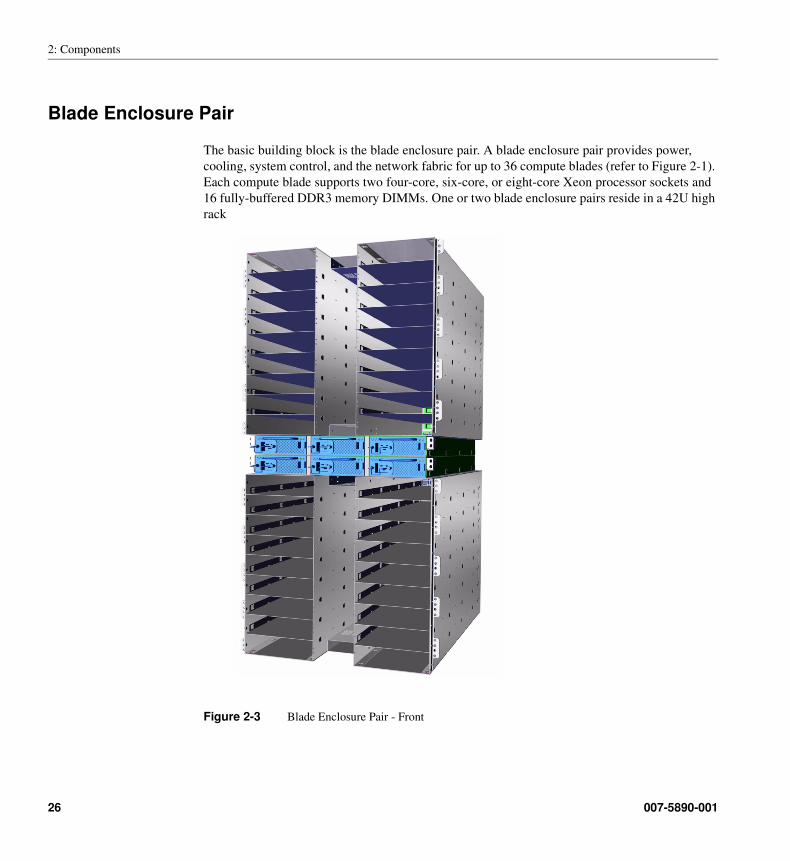
Blade Enclosure Pair
The basic building block is the blade enclosure pair. A blade enclosure pair provides power,
cooling, system control, and the network fabric for up to 36 compute blades (refer to Figure 2-1).
Each compute blade supports two four-core, six-core, or eight-core Xeon processor sockets and
16 fully-buffered DDR3 memory DIMMs. One or two blade enclosure pairs reside in a 42U high
rack
Figure 2-3 Blade Enclosure Pair - Front
26 007-5890-001
Blade Enclosure Pair
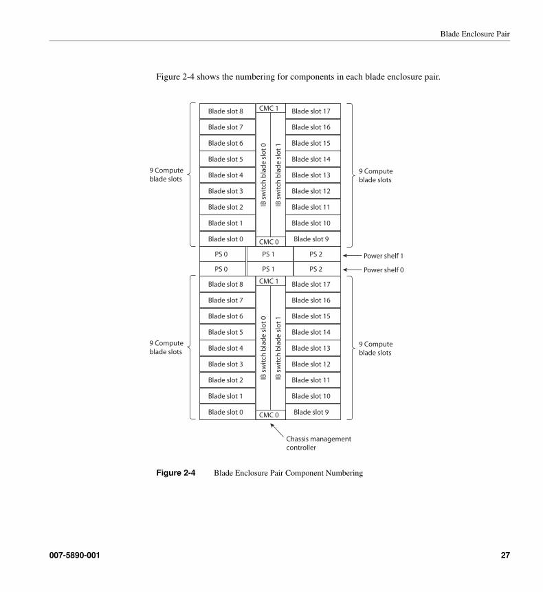
Figure 2-4 shows the numbering for components in each blade enclosure pair.
Figure 2-4 Blade Enclosure Pair Component Numbering
Blade slot 8
Blade slot 7
Blade slot 6
Blade slot 5
Blade slot 4
Blade slot 3
Blade slot 2
Blade slot 1
Blade slot 0
Blade slot 17
Blade slot 16
Blade slot 15
Blade slot 14
Blade slot 13
Blade slot 12
Blade slot 11
Blade slot 10
Blade slot 9
IB s
wit
ch b
lad
e s
lot
1
IB s
wit
ch b
lad
e s
lot
0
CMC 1
CMC 0
PS 0 PS 1 PS 2
PS 0 PS 1 PS 2
Blade slot 8
Blade slot 7
Blade slot 6
Blade slot 5
Blade slot 4
Blade slot 3
Blade slot 2
Blade slot 1
Blade slot 0
Blade slot 17
Blade slot 16
Blade slot 15
Blade slot 14
Blade slot 13
Blade slot 12
Blade slot 11
Blade slot 10
Blade slot 9
IB s
wit
ch b
lad
e s
lot
1
IB s
wit
ch b
lad
e s
lot
0
CMC 1
CMC 0
Chassis management
controller
9 Compute
blade slots
Power shelf 0
Power shelf 1
9 Compute
blade slots
9 Compute
blade slots
9 Compute
blade slots
007-5890-001 27
2: Components
Power Supplies
The blade enclosure pair uses power supplies with two different voltage levels:
• Up to six hot-swappable 3037W 12V power supplies are located between the two blade
enclosures in a rack to provide power to the compute blades.
• Two hot-swappable 3037W 48V power supplies that at located in the fan power box at the
rear of the system provide power to the blowers in the rear of the rack.
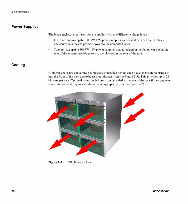
Cooling
A blower enclosure containing six blowers is installed behind each blade enclosure to bring air
into the front of the rack and exhaust it out the rear (refer to Figure 2-5). This provides up to 24
blowers per rack. Optional water-cooled coils can be added to the rear of the rack if the computer
room environment requires additional cooling capacity (refer to Figure 2-2).
Figure 2-5 IRU Blowers - Rear
28 007-5890-001
I/O Expansion Racks
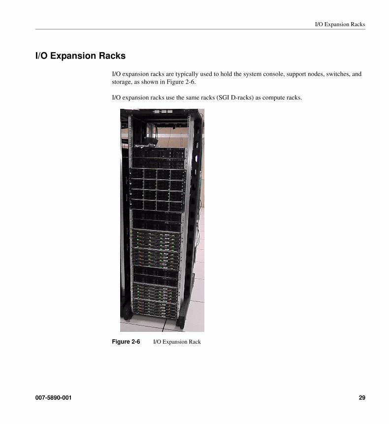
I/O Expansion Racks
I/O expansion racks are typically used to hold the system console, support nodes, switches, and
storage, as shown in Figure 2-6.
I/O expansion racks use the same racks (SGI D-racks) as compute racks.
Figure 2-6 I/O Expansion Rack
007-5890-001 29
2: Components
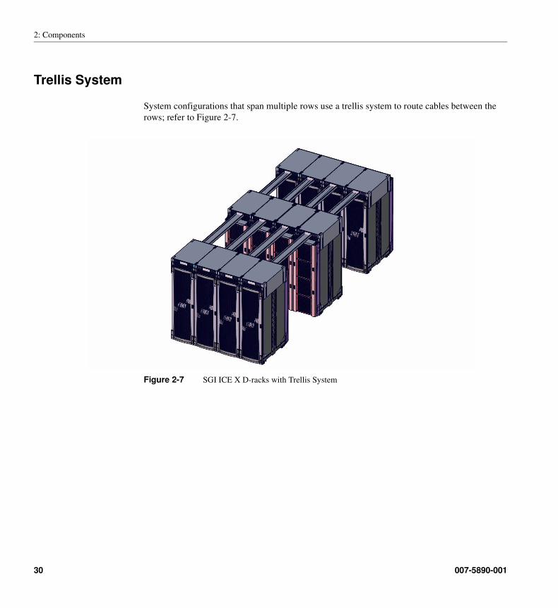
Trellis System
System configurations that span multiple rows use a trellis system to route cables between the
rows; refer to Figure 2-7.
Figure 2-7 SGI ICE X D-racks with Trellis System
30 007-5890-001
Chapter 3
3. Specifications
This section provides a summary of the mechanical, electrical, and environmental specifications
for SGI ICE X systems.
007-5890-001 31
3: Specifications
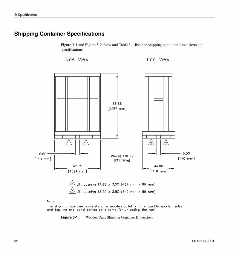
Shipping Container Specifications
Figure 3-1 and Figure 3-2 show and Table 3-1 lists the shipping container dimensions and
specifications.
Figure 3-1 Wooden Crate Shipping Container Dimensions
Weight: 470 lbs
[213.19 kg]
32 007-5890-001
Shipping Container Specifications
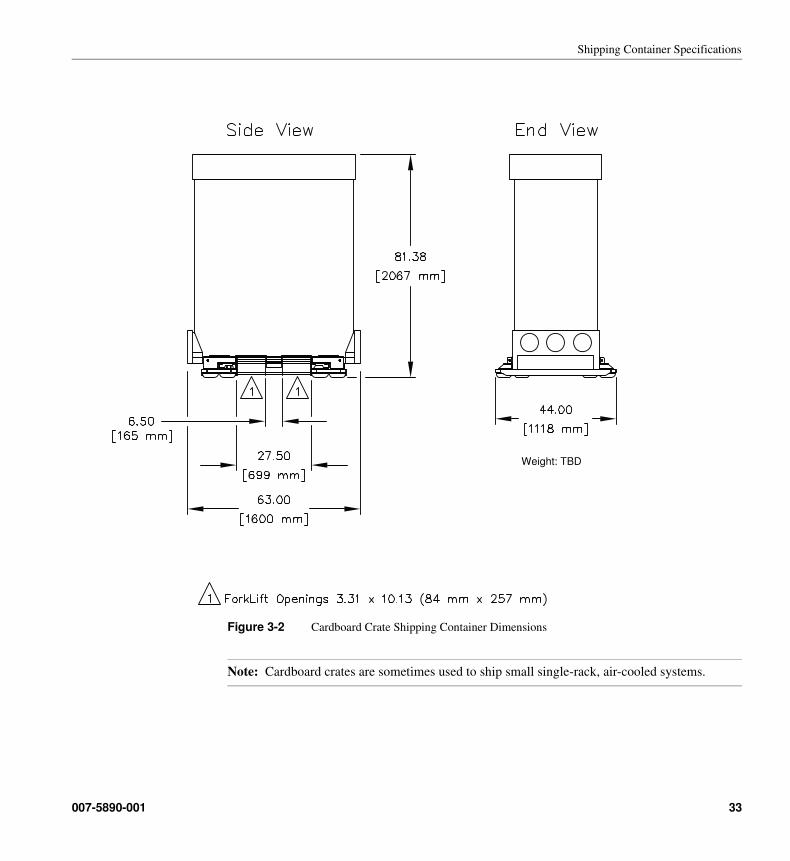
Figure 3-2 Cardboard Crate Shipping Container Dimensions
Note: Cardboard crates are sometimes used to ship small single-rack, air-cooled systems.
Weight: TBD
007-5890-001 33
3: Specifications
Rack Dimensions
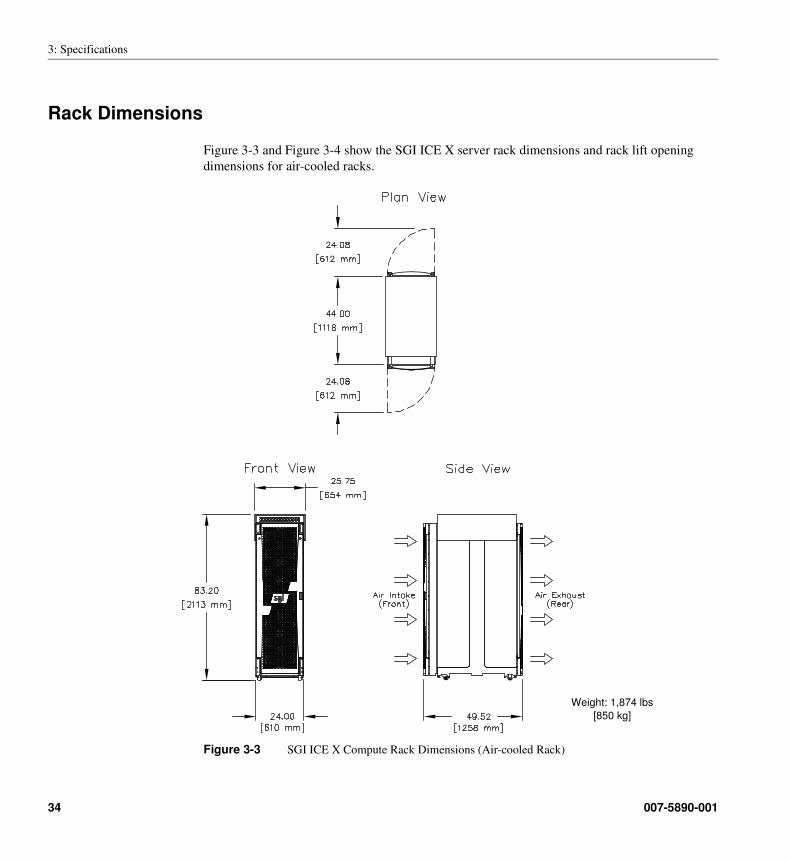
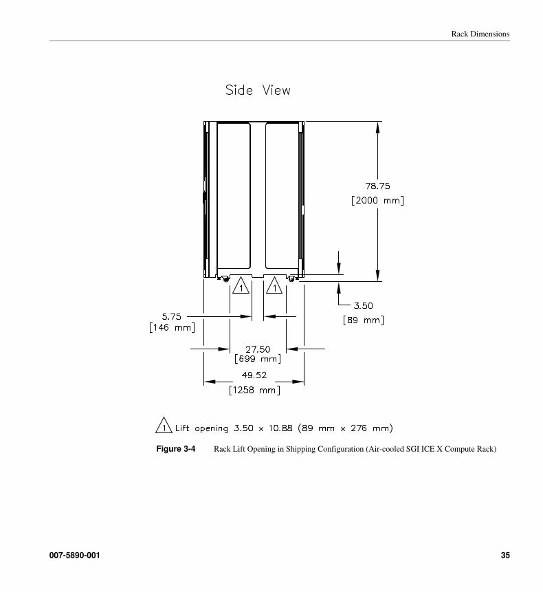
Figure 3-3 and Figure 3-4 show the SGI ICE X server rack dimensions and rack lift opening
dimensions for air-cooled racks.
Figure 3-3 SGI ICE X Compute Rack Dimensions (Air-cooled Rack)
Weight: 1,874 lbs
[850 kg]
34 007-5890-001
Rack Dimensions
Figure 3-4 Rack Lift Opening in Shipping Configuration (Air-cooled SGI ICE X Compute Rack)
007-5890-001 35
3: Specifications
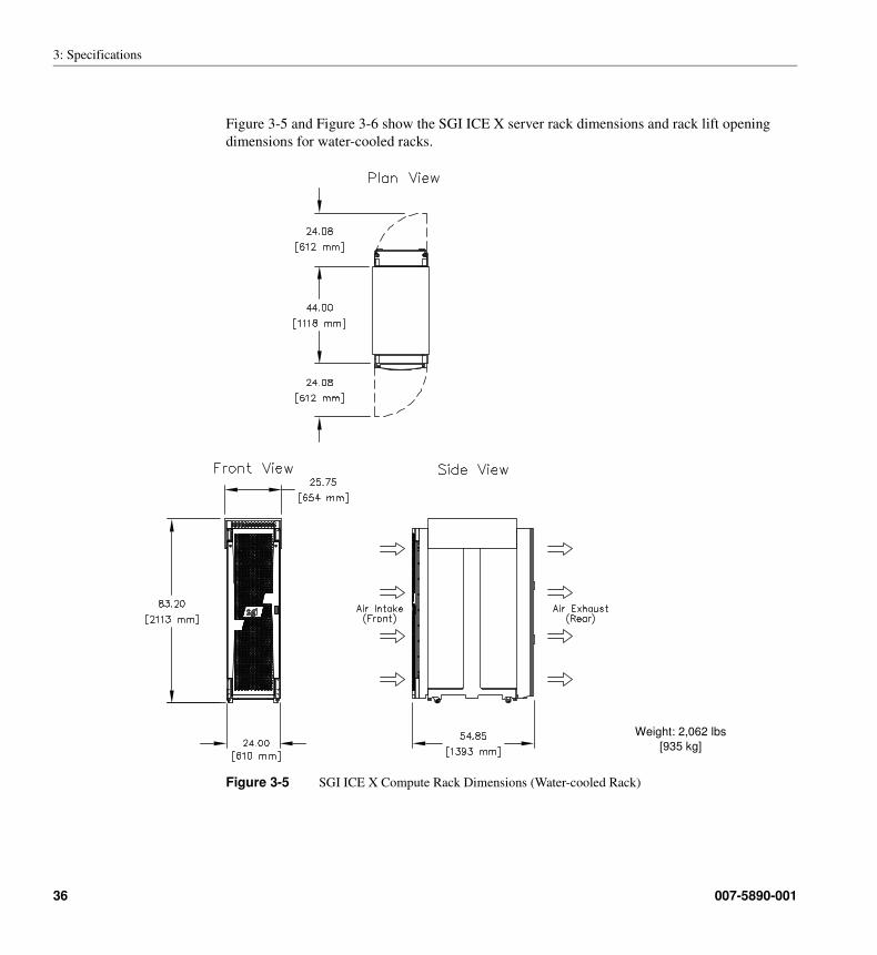
Figure 3-5 and Figure 3-6 show the SGI ICE X server rack dimensions and rack lift opening
dimensions for water-cooled racks.
Figure 3-5 SGI ICE X Compute Rack Dimensions (Water-cooled Rack)
Weight: 2,062 lbs
[935 kg]
36 007-5890-001
Rack Dimensions
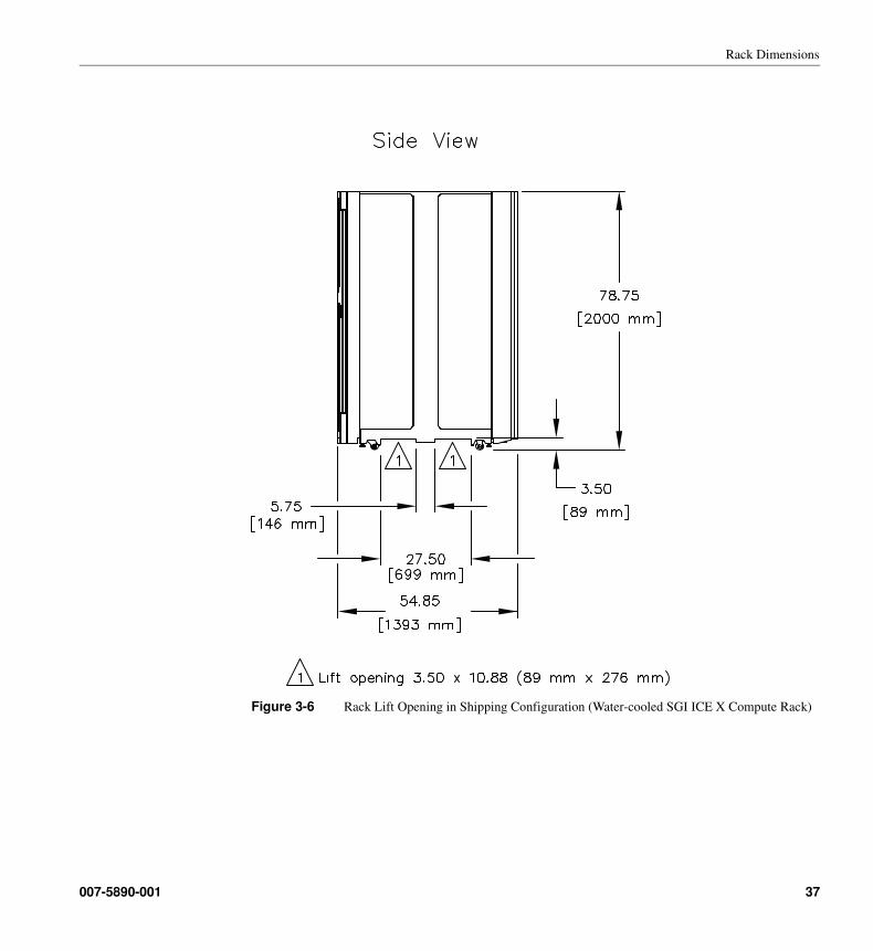
Figure 3-6 Rack Lift Opening in Shipping Configuration (Water-cooled SGI ICE X Compute Rack)
007-5890-001 37
3: Specifications
Rack Spacing
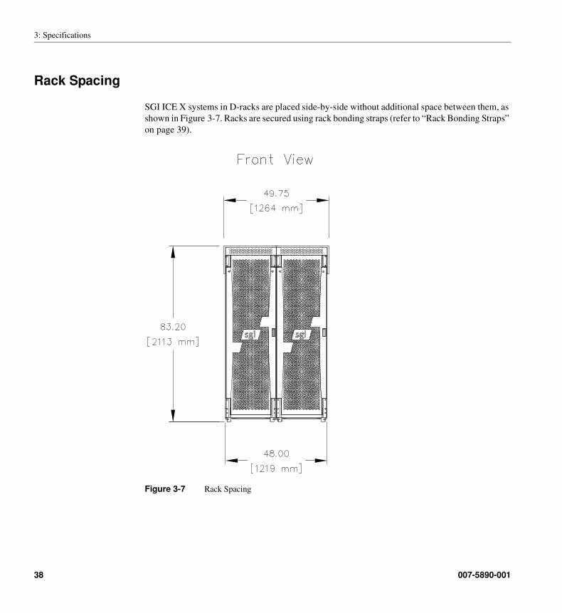
SGI ICE X systems in D-racks are placed side-by-side without additional space between them, as
shown in Figure 3-7. Racks are secured using rack bonding straps (refer to “Rack Bonding Straps”
on page 39).
Figure 3-7 Rack Spacing
38 007-5890-001
Rack Spacing
Rack Bonding Straps
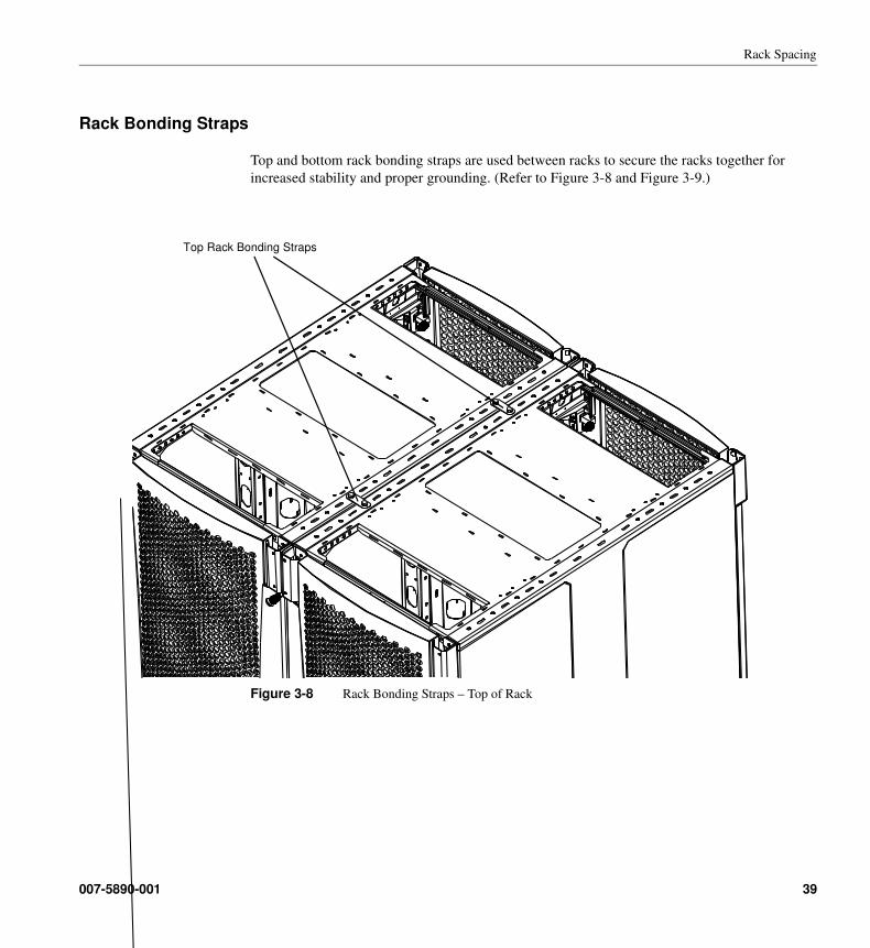
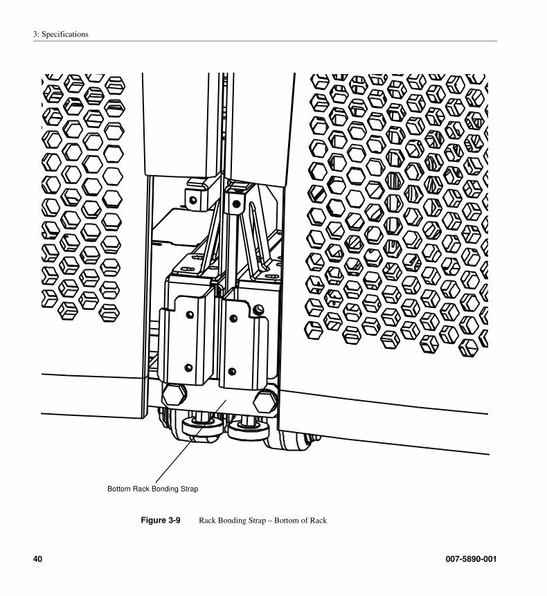
Top and bottom rack bonding straps are used between racks to secure the racks together for
increased stability and proper grounding. (Refer to Figure 3-8 and Figure 3-9.)
Figure 3-8 Rack Bonding Straps – Top of Rack
Top Rack Bonding Straps
007-5890-001 39
3: Specifications
Figure 3-9 Rack Bonding Strap – Bottom of Rack
Bottom Rack Bonding Strap
40 007-5890-001
System Specifications
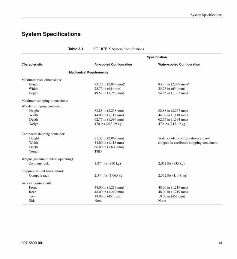
System Specifications
Table 3-1 SGI ICE X System Specifications
Specification
Characteristic Air-cooled Configuration Water-cooled Configuration
Mechanical Requirements
Maximum rack dimensions:
Height
Width
Depth
83.20 in (2,089 mm)a
25.75 in (654 mm)
49.52 in (1,258 mm)
83.20 in (2,089 mm)a
25.75 in (654 mm)
54.85 in (1,393 mm)
Maximum shipping dimensions:
Wooden shipping container:
Height
Width
Depth
Weight
Cardboard shipping container:
Height
Width
Depth
Weight
88.88 in (2,258 mm)
44.00 in (1,118 mm)
62.75 in (1,594 mm)
470 lbs (213.19 kg)
81.38 in (2,067 mm)
44.00 in (1,118 mm)
66.00 in (1,600 mm)
TBD
88.88 in (2,257 mm)
44.00 in (1,118 mm)
62.75 in (1,594 mm)
470 lbs (213.19 kg)
Water-cooled configurations are not
shipped in cardboard shipping containers.
Weight (maximum while operating):
Compute rack
1,874 lbs (850 kg)
2,062 lbs (935 kg)
Shipping weight (maximum):
Compute rack
2,344 lbs (1,063 kg)
2,532 lbs (1,148 kg)
Access requirements:
Front
Rear
Top
Side
48.00 in (1,219 mm)
48.00 in (1,219 mm)
18.00 in (457 mm)
None
48.00 in (1,219 mm)
48.00 in (1,219 mm)
18.00 in (457 mm)
None
007-5890-001 41
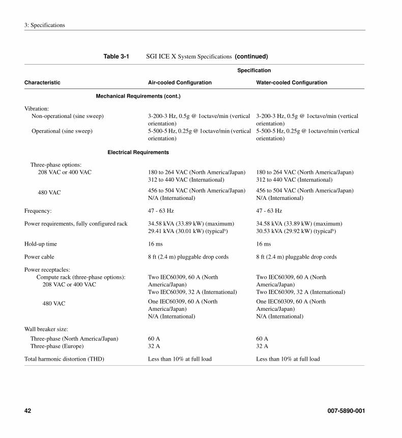
3: Specifications
Mechanical Requirements (cont.)
Vibration:
Non-operational (sine sweep)
Operational (sine sweep)
3-200-3 Hz, 0.5g @ 1octave/min (vertical
orientation)
5-500-5 Hz, 0.25g @ 1octave/min (vertical
orientation)
3-200-3 Hz, 0.5g @ 1octave/min (vertical
orientation)
5-500-5 Hz, 0.25g @ 1octave/min (vertical
orientation)
Electrical Requirements
Three-phase options:
208 VAC or 400 VAC
480 VAC
180 to 264 VAC (North America/Japan)
312 to 440 VAC (International)
456 to 504 VAC (North America/Japan)
N/A (International)
180 to 264 VAC (North America/Japan)
312 to 440 VAC (International)
456 to 504 VAC (North America/Japan)
N/A (International)
Frequency: 47 - 63 Hz 47 - 63 Hz
Power requirements, fully configured rack 34.58 kVA (33.89 kW) (maximum)
29.41 kVA (30.01 kW) (typicalb)
34.58 kVA (33.89 kW) (maximum)
30.53 kVA (29.92 kW) (typicalb)
Hold-up time 16 ms 16 ms
Power cable 8 ft (2.4 m) pluggable drop cords 8 ft (2.4 m) pluggable drop cords
Power receptacles:
Compute rack (three-phase options):
208 VAC or 400 VAC
480 VAC
Two IEC60309, 60 A (North
America/Japan)
Two IEC60309, 32 A (International)
One IEC60309, 60 A (North
America/Japan)
N/A (International)
Two IEC60309, 60 A (North
America/Japan)
Two IEC60309, 32 A (International)
One IEC60309, 60 A (North
America/Japan)
N/A (International)
Wall breaker size:
Three-phase (North America/Japan)
Three-phase (Europe)
60 A
32 A
60 A
32 A
Total harmonic distortion (THD) Less than 10% at full load Less than 10% at full load
Table 3-1 SGI ICE X System Specifications (continued)
Specification
Characteristic Air-cooled Configuration Water-cooled Configuration
42 007-5890-001
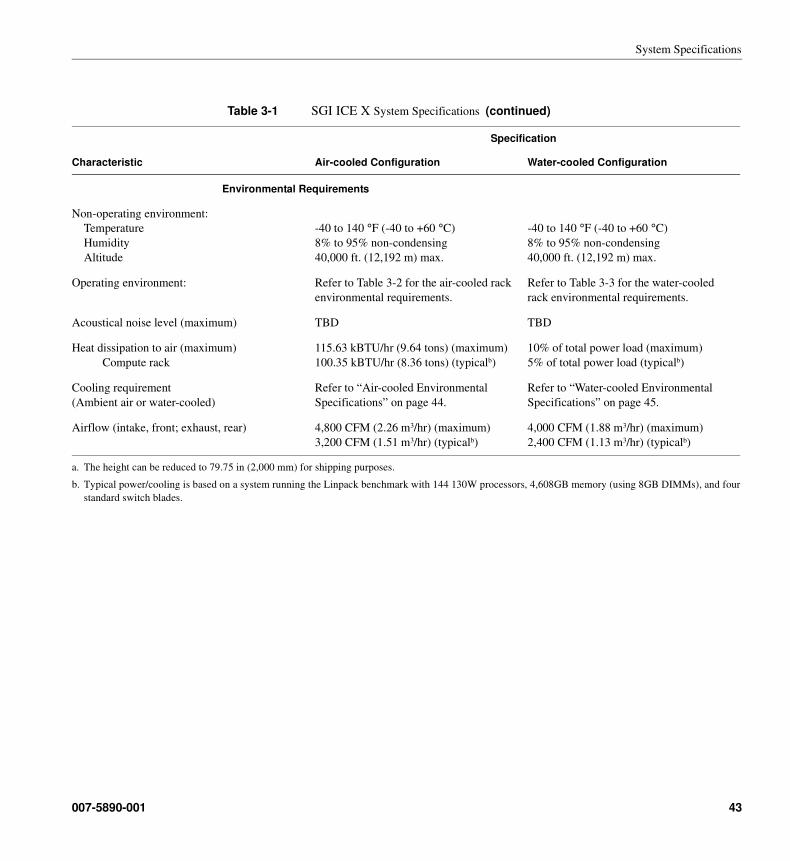
System Specifications
Environmental Requirements
Non-operating environment:
Temperature
Humidity
Altitude
-40 to 140 °F (-40 to +60 °C)
8% to 95% non-condensing
40,000 ft. (12,192 m) max.
-40 to 140 °F (-40 to +60 °C)
8% to 95% non-condensing
40,000 ft. (12,192 m) max.
Operating environment: Refer to Table 3-2 for the air-cooled rack
environmental requirements.
Refer to Table 3-3 for the water-cooled
rack environmental requirements.
Acoustical noise level (maximum) TBD TBD
Heat dissipation to air (maximum)
Compute rack
115.63 kBTU/hr (9.64 tons) (maximum)
100.35 kBTU/hr (8.36 tons) (typicalb)
10% of total power load (maximum)
5% of total power load (typicalb)
Cooling requirement
(Ambient air or water-cooled)
Refer to “Air-cooled Environmental
Specifications” on page 44.
Refer to “Water-cooled Environmental
Specifications” on page 45.
Airflow (intake, front; exhaust, rear) 4,800 CFM (2.26 m3/hr) (maximum)
3,200 CFM (1.51 m3/hr) (typicalb)
4,000 CFM (1.88 m3/hr) (maximum)
2,400 CFM (1.13 m3/hr) (typicalb)
a. The height can be reduced to 79.75 in (2,000 mm) for shipping purposes.
b. Typical power/cooling is based on a system running the Linpack benchmark with 144 130W processors, 4,608GB memory (using 8GB DIMMs), and four
standard switch blades.
Table 3-1 SGI ICE X System Specifications (continued)
Specification
Characteristic Air-cooled Configuration Water-cooled Configuration
007-5890-001 43
3: Specifications
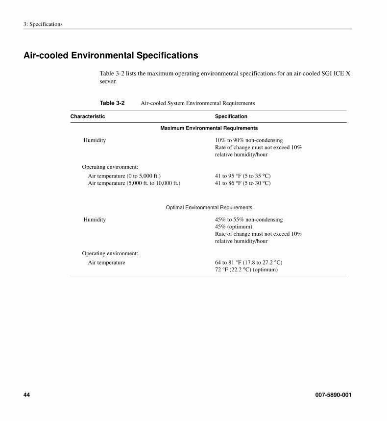
Air-cooled Environmental Specifications
Table 3-2 lists the maximum operating environmental specifications for an air-cooled SGI ICE X
server.
Table 3-2 Air-cooled System Environmental Requirements
Characteristic Specification
Maximum Environmental Requirements
Humidity 10% to 90% non-condensing
Rate of change must not exceed 10%
relative humidity/hour
Operating environment:
Air temperature (0 to 5,000 ft.)
Air temperature (5,000 ft. to 10,000 ft.)
41 to 95 °F (5 to 35 °C)
41 to 86 °F (5 to 30 °C)
Optimal Environmental Requirements
Humidity 45% to 55% non-condensing
45% (optimum)
Rate of change must not exceed 10%
relative humidity/hour
Operating environment:
Air temperature 64 to 81 °F (17.8 to 27.2 °C)
72 °F (22.2 °C) (optimum)
44 007-5890-001
Water-cooled Environmental Specifications
Water-cooled Environmental Specifications
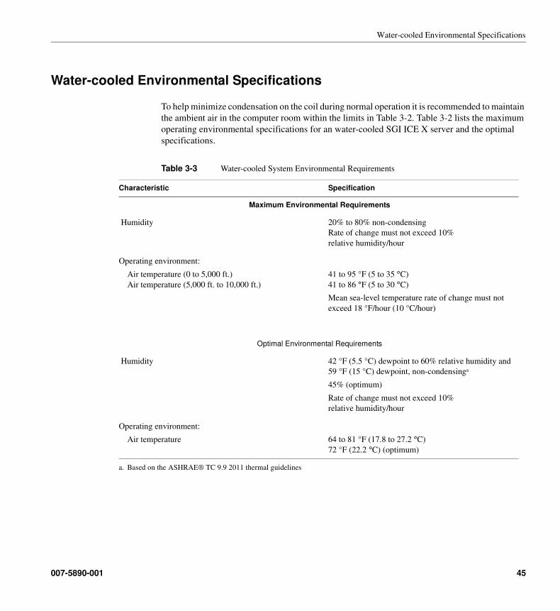
To help minimize condensation on the coil during normal operation it is recommended to maintain
the ambient air in the computer room within the limits in Table 3-2. Table 3-2 lists the maximum
operating environmental specifications for an water-cooled SGI ICE X server and the optimal
specifications.
Table 3-3 Water-cooled System Environmental Requirements
Characteristic Specification
Maximum Environmental Requirements
Humidity 20% to 80% non-condensing
Rate of change must not exceed 10%
relative humidity/hour
Operating environment:
Air temperature (0 to 5,000 ft.)
Air temperature (5,000 ft. to 10,000 ft.)
41 to 95 °F (5 to 35 °C)
41 to 86 °F (5 to 30 °C)
Mean sea-level temperature rate of change must not
exceed 18 °F/hour (10 °C/hour)
Optimal Environmental Requirements
Humidity 42 °F (5.5 °C) dewpoint to 60% relative humidity and
59 °F (15 °C) dewpoint, non-condensinga
45% (optimum)
Rate of change must not exceed 10%
relative humidity/hour
a. Based on the ASHRAE® TC 9.9 2011 thermal guidelines
Operating environment:
Air temperature 64 to 81 °F (17.8 to 27.2 °C)
72 °F (22.2 °C) (optimum)
007-5890-001 45
3: Specifications
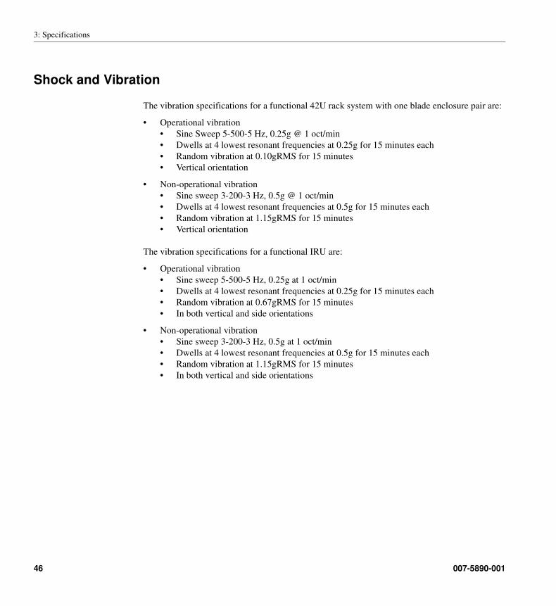
Shock and Vibration
The vibration specifications for a functional 42U rack system with one blade enclosure pair are:
• Operational vibration
• Sine Sweep 5-500-5 Hz, 0.25g @ 1 oct/min
• Dwells at 4 lowest resonant frequencies at 0.25g for 15 minutes each
• Random vibration at 0.10gRMS for 15 minutes
• Vertical orientation
• Non-operational vibration
• Sine sweep 3-200-3 Hz, 0.5g @ 1 oct/min
• Dwells at 4 lowest resonant frequencies at 0.5g for 15 minutes each
• Random vibration at 1.15gRMS for 15 minutes
• Vertical orientation
The vibration specifications for a functional IRU are:
• Operational vibration
• Sine sweep 5-500-5 Hz, 0.25g at 1 oct/min
• Dwells at 4 lowest resonant frequencies at 0.25g for 15 minutes each
• Random vibration at 0.67gRMS for 15 minutes
• In both vertical and side orientations
• Non-operational vibration
• Sine sweep 3-200-3 Hz, 0.5g at 1 oct/min
• Dwells at 4 lowest resonant frequencies at 0.5g for 15 minutes each
• Random vibration at 1.15gRMS for 15 minutes
• In both vertical and side orientations
46 007-5890-001
Chapter 4
4. Layouts and Clearances
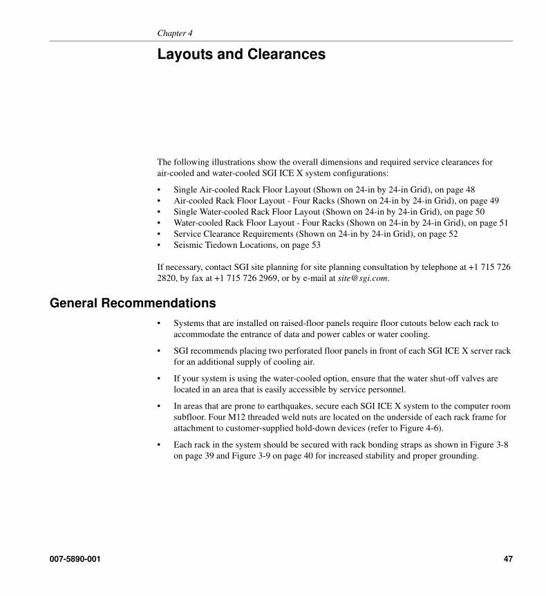
The following illustrations show the overall dimensions and required service clearances for
air-cooled and water-cooled SGI ICE X system configurations:
• Single Air-cooled Rack Floor Layout (Shown on 24-in by 24-in Grid), on page 48
• Air-cooled Rack Floor Layout - Four Racks (Shown on 24-in by 24-in Grid), on page 49
• Single Water-cooled Rack Floor Layout (Shown on 24-in by 24-in Grid), on page 50
• Water-cooled Rack Floor Layout - Four Racks (Shown on 24-in by 24-in Grid), on page 51
• Service Clearance Requirements (Shown on 24-in by 24-in Grid), on page 52
• Seismic Tiedown Locations, on page 53
If necessary, contact SGI site planning for site planning consultation by telephone at +1 715 726
2820, by fax at +1 715 726 2969, or by e-mail at [email protected].
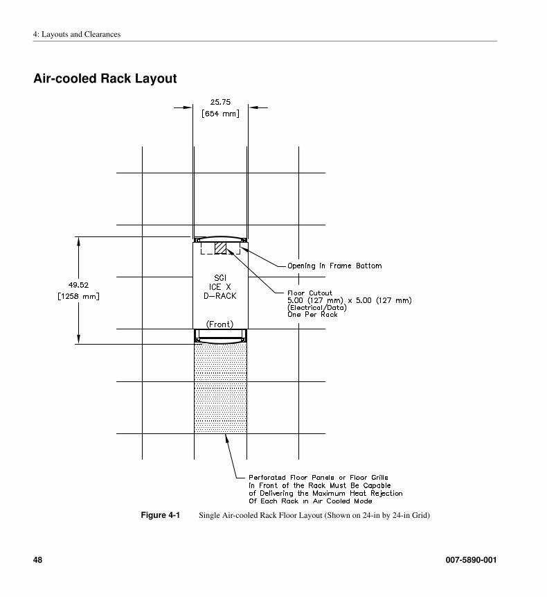
General Recommendations
• Systems that are installed on raised-floor panels require floor cutouts below each rack to
accommodate the entrance of data and power cables or water cooling.
• SGI recommends placing two perforated floor panels in front of each SGI ICE X server rack
for an additional supply of cooling air.
• If your system is using the water-cooled option, ensure that the water shut-off valves are
located in an area that is easily accessible by service personnel.
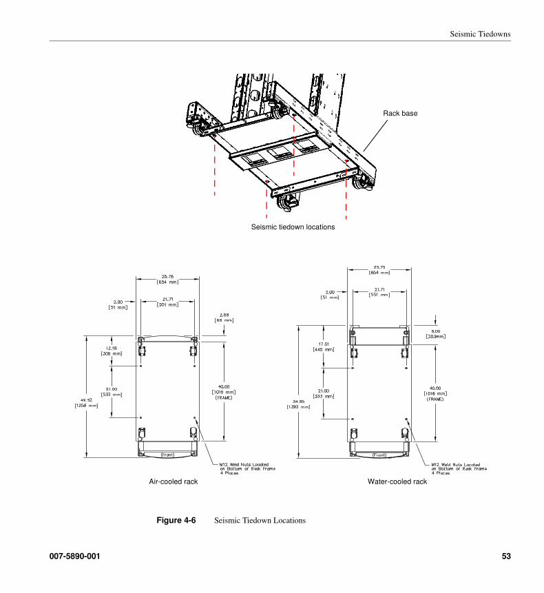
• In areas that are prone to earthquakes, secure each SGI ICE X system to the computer room
subfloor. Four M12 threaded weld nuts are located on the underside of each rack frame for
attachment to customer-supplied hold-down devices (refer to Figure 4-6).
• Each rack in the system should be secured with rack bonding straps as shown in Figure 3-8
on page 39 and Figure 3-9 on page 40 for increased stability and proper grounding.
007-5890-001 47
4: Layouts and Clearances
Air-cooled Rack Layout
Figure 4-1 Single Air-cooled Rack Floor Layout (Shown on 24-in by 24-in Grid)
48 007-5890-001
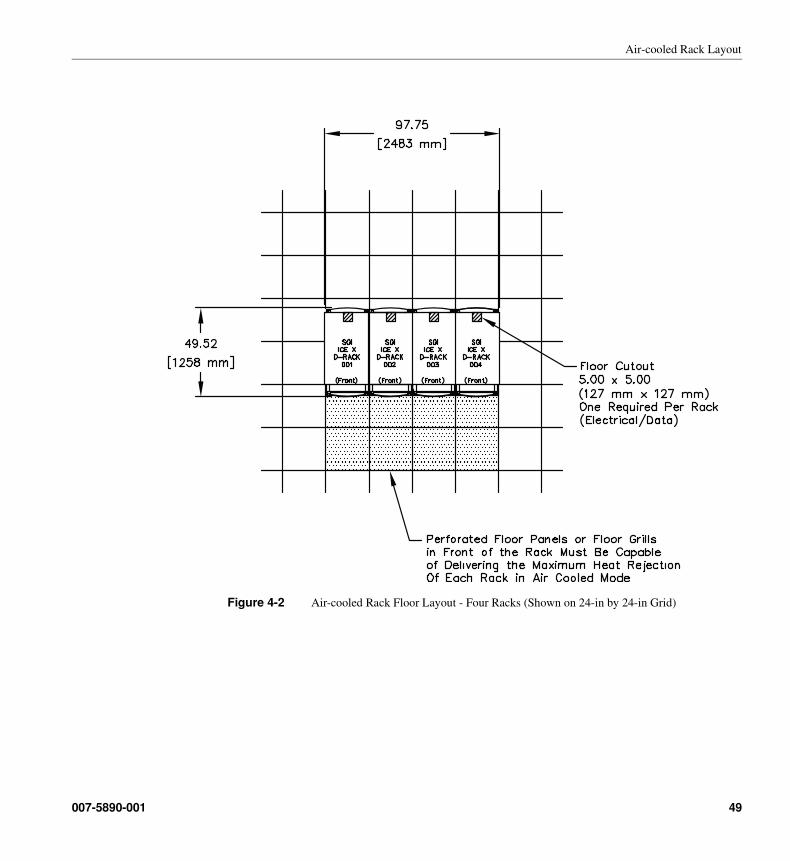
Air-cooled Rack Layout
Figure 4-2 Air-cooled Rack Floor Layout - Four Racks (Shown on 24-in by 24-in Grid)
007-5890-001 49
4: Layouts and Clearances
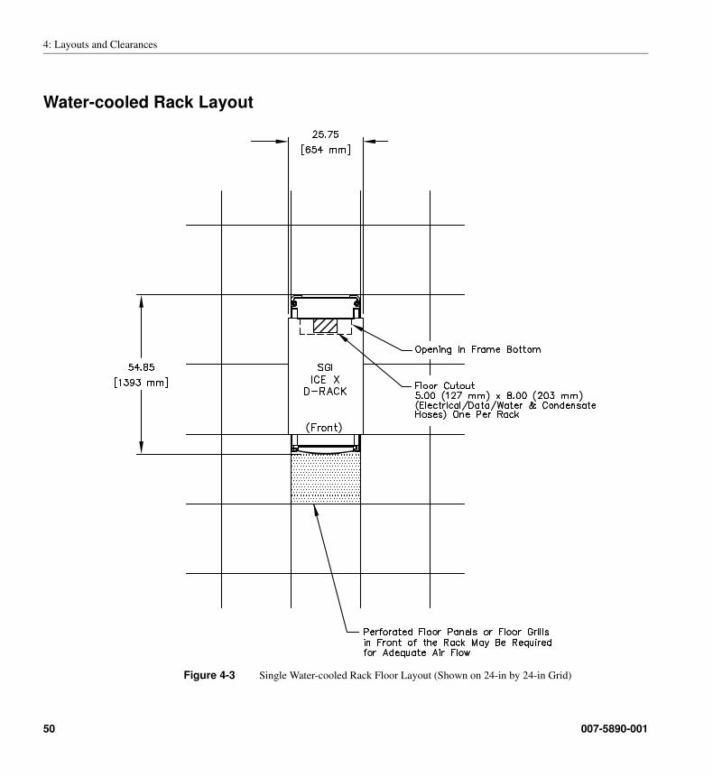
Water-cooled Rack Layout
Figure 4-3 Single Water-cooled Rack Floor Layout (Shown on 24-in by 24-in Grid)
50 007-5890-001
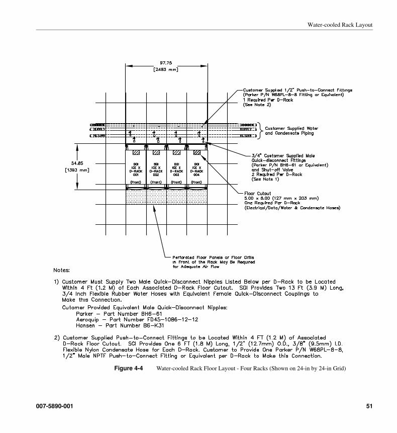
Water-cooled Rack Layout
Figure 4-4 Water-cooled Rack Floor Layout - Four Racks (Shown on 24-in by 24-in Grid)
007-5890-001 51
4: Layouts and Clearances
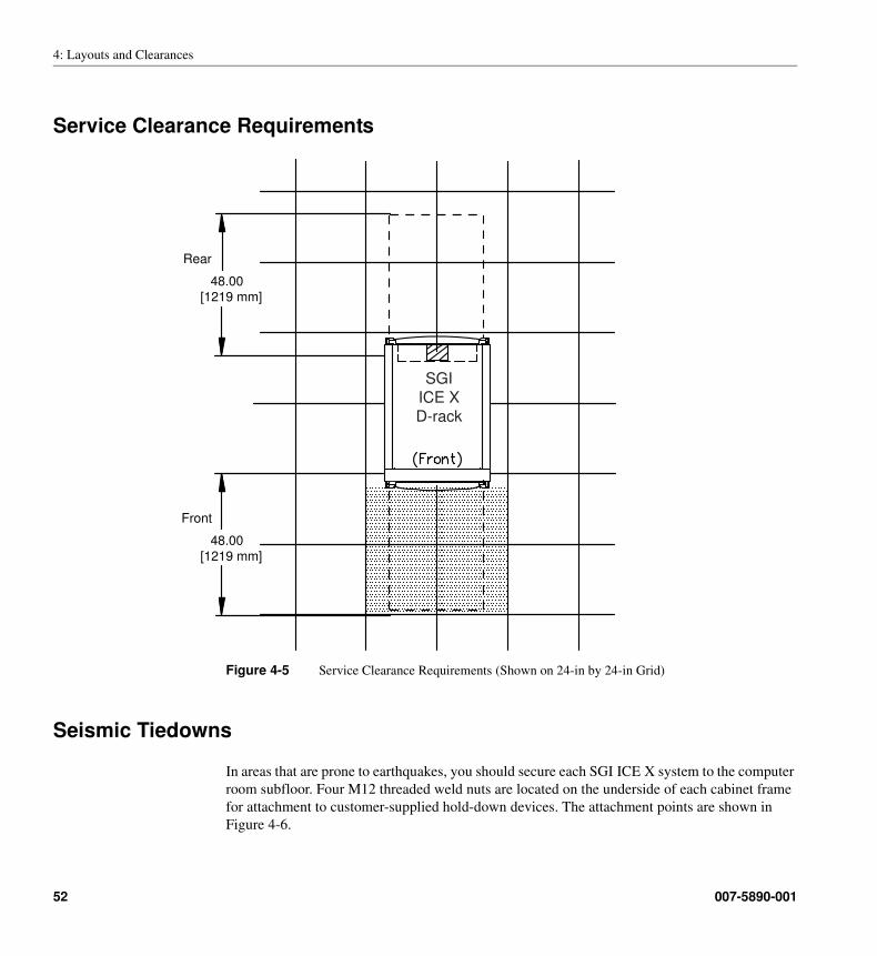
Service Clearance Requirements
Figure 4-5 Service Clearance Requirements (Shown on 24-in by 24-in Grid)
Seismic Tiedowns
In areas that are prone to earthquakes, you should secure each SGI ICE X system to the computer
room subfloor. Four M12 threaded weld nuts are located on the underside of each cabinet frame
for attachment to customer-supplied hold-down devices. The attachment points are shown in
Figure 4-6.
48.00
[1219 mm]
Front
48.00
[1219 mm]
Rear
SGI
ICE X
D-rack
52 007-5890-001
Seismic Tiedowns
Figure 4-6 Seismic Tiedown Locations
Rack base
Seismic tiedown locations
Air-cooled rack Water-cooled rack
007-5890-001 53
4: Layouts and Clearances
54 007-5890-001
Chapter 5
5. Site Planning Checklist
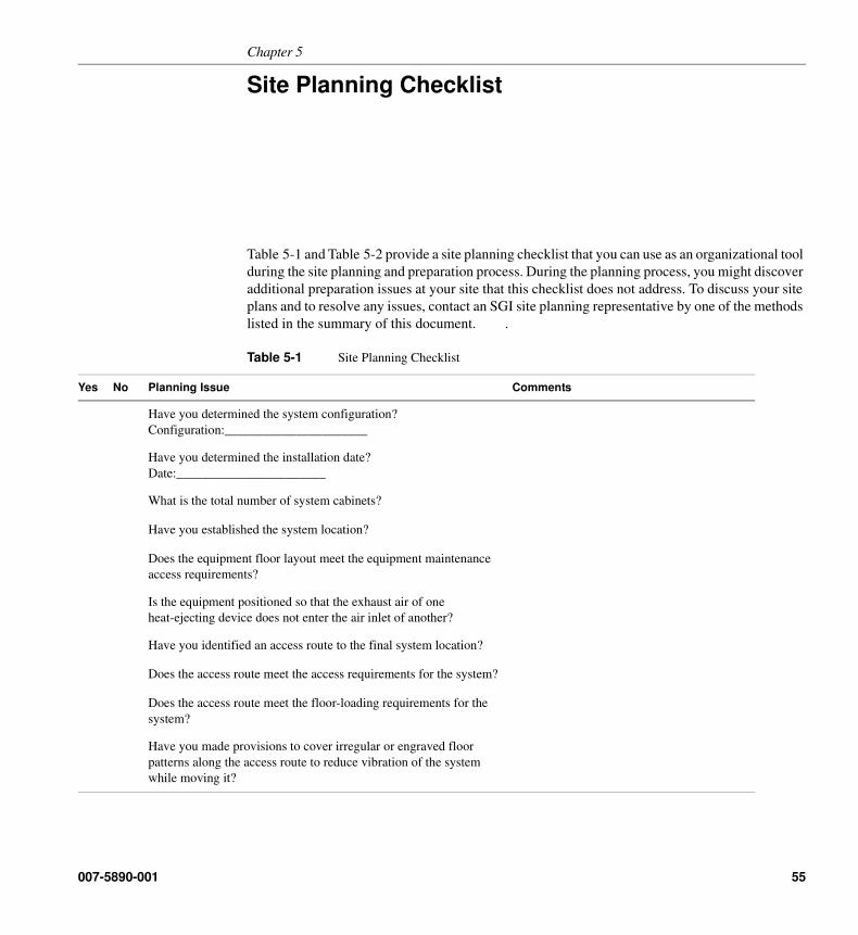
Table 5-1 and Table 5-2 provide a site planning checklist that you can use as an organizational tool
during the site planning and preparation process. During the planning process, you might discover
additional preparation issues at your site that this checklist does not address. To discuss your site
plans and to resolve any issues, contact an SGI site planning representative by one of the methods
listed in the summary of this document. .
Table 5-1 Site Planning Checklist
Yes No Planning Issue Comments
Have you determined the system configuration?
Configuration:______________________
Have you determined the installation date?
Date:_______________________
What is the total number of system cabinets?
Have you established the system location?
Does the equipment floor layout meet the equipment maintenance
access requirements?
Is the equipment positioned so that the exhaust air of one
heat-ejecting device does not enter the air inlet of another?
Have you identified an access route to the final system location?
Does the access route meet the access requirements for the system?
Does the access route meet the floor-loading requirements for the
system?
Have you made provisions to cover irregular or engraved floor
patterns along the access route to reduce vibration of the system
while moving it?
007-5890-001 55
5: Site Planning Checklist
Does your loading dock meet standard freight-carrier truck
requirements? If not, have you allocated a forklift for delivery?
Contact your site planning representative if you have concerns about
your loading dock.
Is a pallet jack available on-site to move the system in its shipping
container to the final system location?
Do the pallet-jack fork dimensions meet the requirements for the
shipping container?
Are the elevator and elevator door dimensions adequate?
Is the elevator weight capacity adequate?
Does each ramp in the access route have an incline that is less than 10
degrees?
Did you order the power receptacles for your system?
Are the circuit breakers for all cabinets properly installed and
labeled?
Are all power receptacles properly installed and labeled?
Are the floor cutouts properly positioned and free of sharp edges?
Are the recommended perforated floor panels properly positioned?
Is the computer room floor strong enough to support the weight of the
system?
Can the computer room environment be properly maintained within
the specifications listed in Table 3-1 on page 41?
Are telephone lines installed if you plan to implement remote support
for your system?
Have you trained system administrators or enrolled operators in the
necessary training courses?
http://www.hpctraining.com
Table 5-1 Site Planning Checklist
Yes No Planning Issue Comments
56 007-5890-001
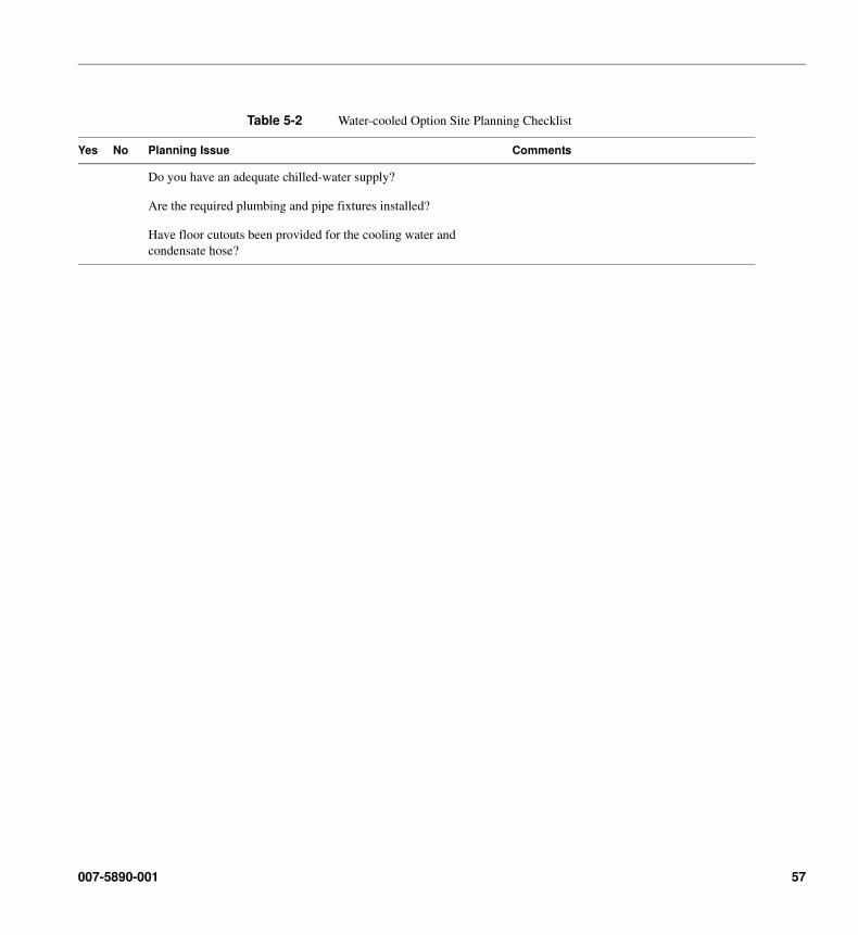
Table 5-2 Water-cooled Option Site Planning Checklist
Yes No Planning Issue Comments
Do you have an adequate chilled-water supply?
Are the required plumbing and pipe fixtures installed?
Have floor cutouts been provided for the cooling water and
condensate hose?
007-5890-001 57
5: Site Planning Checklist
58 007-5890-001
![001 โปรแกรมทัวร์ขายหน้า · 001 by cuc--easy น่ารัก in shanghai 4d3n==(nov'17-feb'18)_[xw] 007 ทัวร์ต่างประเทศ\001](https://img.pdfslide.net/doc/110x75/5e3b558d7a687e051b64fdf5/001-aaaaaaaaaaaaoeaaaaaaa-001-by-cuc-easy-aaaaaa.jpg)