Embed Size (px)
Citation preview
SIM808 GPRS/GSM+GPS Shield v1.0Introduction
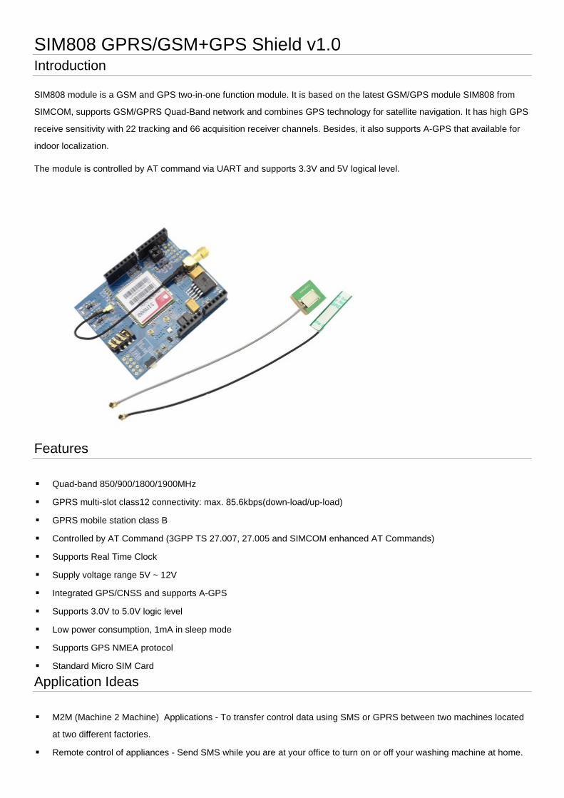
SIM808 module is a GSM and GPS two-in-one function module. It is based on the latest GSM/GPS module SIM808 from
SIMCOM, supports GSM/GPRS Quad-Band network and combines GPS technology for satellite navigation. It has high GPS
receive sensitivity with 22 tracking and 66 acquisition receiver channels. Besides, it also supports A-GPS that available for
indoor localization.
The module is controlled by AT command via UART and supports 3.3V and 5V logical level.
Features
Quad-band 850/900/1800/1900MHz
GPRS multi-slot class12 connectivity: max. 85.6kbps(down-load/up-load)
GPRS mobile station class B
Controlled by AT Command (3GPP TS 27.007, 27.005 and SIMCOM enhanced AT Commands)
Supports Real Time Clock
Supply voltage range 5V ~ 12V
Integrated GPS/CNSS and supports A-GPS
Supports 3.0V to 5.0V logic level
Low power consumption, 1mA in sleep mode
Supports GPS NMEA protocol
Standard Micro SIM Card
Application Ideas
M2M (Machine 2 Machine) Applications - To transfer control data using SMS or GPRS between two machines located
at two different factories.
Remote control of appliances - Send SMS while you are at your office to turn on or off your washing machine at home.
Remote Weather station or a Wireless Sensor Network - Make it with [ Crowduino v1.0|Crowduino v1.0 ] and create a
sensor node capable of transferring sensor data (like from a weather station - temperature, humidity etc.) to a web
server (like pachube.com).
Vehicle Tracking System - Install GPRS+GSM+GPS Shield in your car and publish your location live on the internet.
Can be used as a automotive burglar alarm.
Cautions
Make sure your SIM card is unlocked.
The product is provided as is without an insulating enclosure. Please observe ESD precautions
especially in dry (low humidity) weather.
The factory default setting for the GPRS Shield UART is autoboading. It supports baud rate
from 1200 bps to 115200bps. (Can be changed using AT commands).
Specifications
Item Min Typical Max
Voltage 4.8 5.0 12
Current 2 - 500
Dimension(with antenna) Arduino shield
Net Weight 47±2
Interface Function
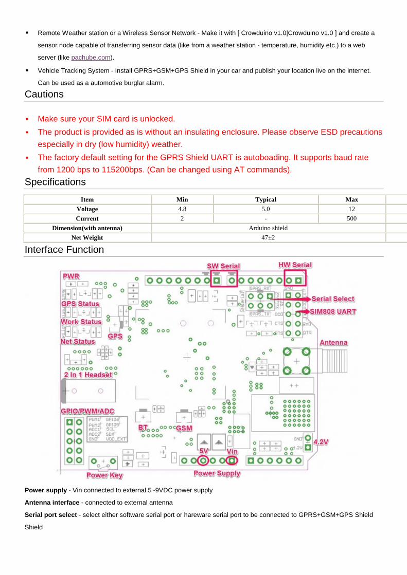
Power supply - Vin connected to external 5~9VDC power supply
Antenna interface - connected to external antenna
Serial port select - select either software serial port or hareware serial port to be connected to GPRS+GSM+GPS Shield
Shield
Hardware Serial - D0/D1 of Arduino/Crowduino
Software serial - D7/D8 of Arduino/Crowduino
Status LED - tell whether the power of SIM808 is on
Net light - tell the status about SIM808 linking to the net
1PPS - tell the status about SIM808 get the location
UART of SIM808 - UART pins breakout of SIM808
Microphone - to answer the phone call
Speaker - to answer the phone call
GPIO,PWM and ADC of SIM808 - GPIO,PWM and ADC pins breakout of SIM808
Power key - power up and down for SIM808
Pins usage on Arduino
D0 - Unused if you select hardware serial port to communicate with GPRS+GSM+GPS Shield
D1 - Unused if you select hardware serial port to communicate with GPRS+GSM+GPS Shield
D2 - Unused
D3 - Unused
D4 - Unused
D5 - Unused
D6 - Unused
D7 - Used if you select software serial port to communicate with GPRS+GSM+GPS Shield
D8 - Used if you select software serial port to communicate with GPRS+GSM+GPS Shield
D9 - Used for software control the power up or down of the SIM808
D10 - Unused
D11 - Unused
D12 - Unused
D13 - Unused
D14(A0) - Unused
D15(A1) - Unused
D16(A2) - Unused
D17(A3) - Unused
D18(A4) - Unused
D19(A5) - Unused
Usage
Hardware installation
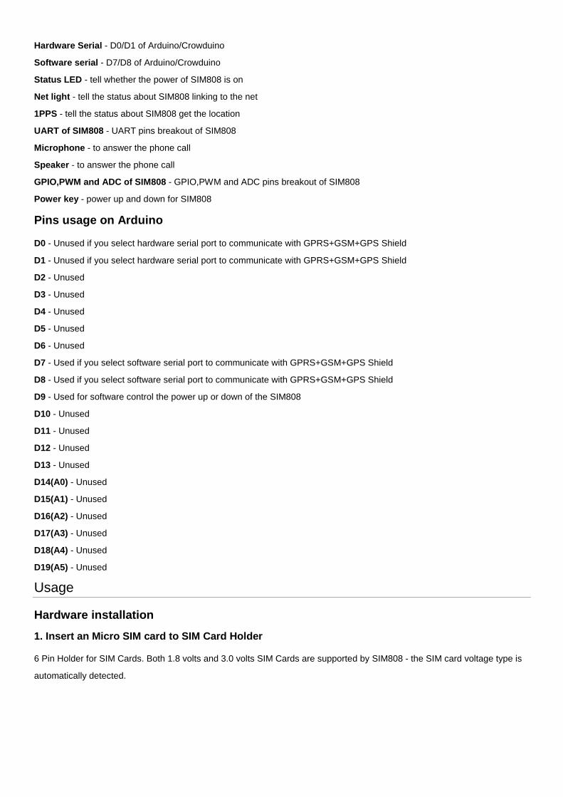
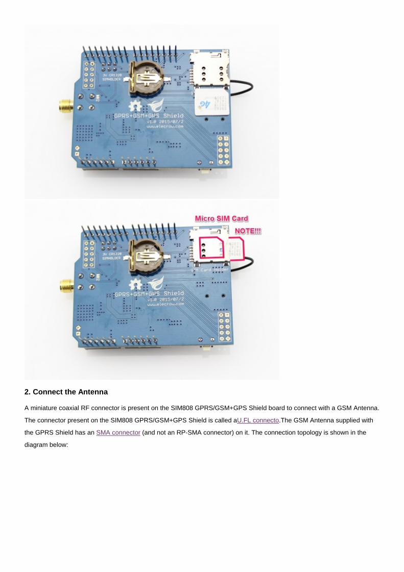
1. Insert an Micro SIM card to SIM Card Holder
6 Pin Holder for SIM Cards. Both 1.8 volts and 3.0 volts SIM Cards are supported by SIM808 - the SIM card voltage type is
automatically detected.
2. Connect the Antenna
A miniature coaxial RF connector is present on the SIM808 GPRS/GSM+GPS Shield board to connect with a GSM Antenna.
The connector present on the SIM808 GPRS/GSM+GPS Shield is called aU.FL connecto.The GSM Antenna supplied with
the GPRS Shield has an SMA connector (and not an RP-SMA connector) on it. The connection topology is shown in the
diagram below:
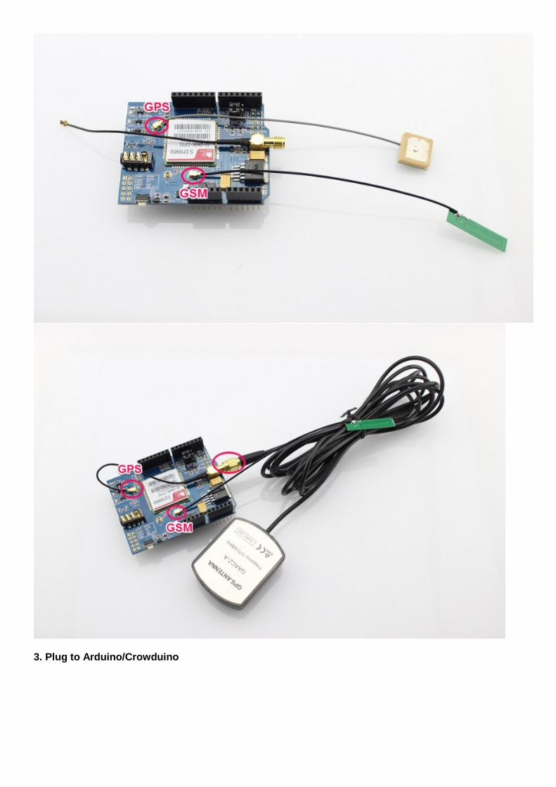
3. Plug to Arduino/Crowduino
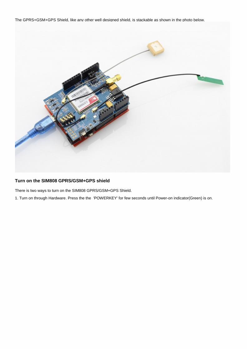
The GPRS+GSM+GPS Shield, like any other well designed shield, is stackable as shown in the photo below.
Turn on the SIM808 GPRS/GSM+GPS shield
There is two ways to turn on the SIM808 GPRS/GSM+GPS Shield.
1. Turn on through Hardware. Press the the 'POWERKEY' for few seconds until Power-on indicator(Green) is on.
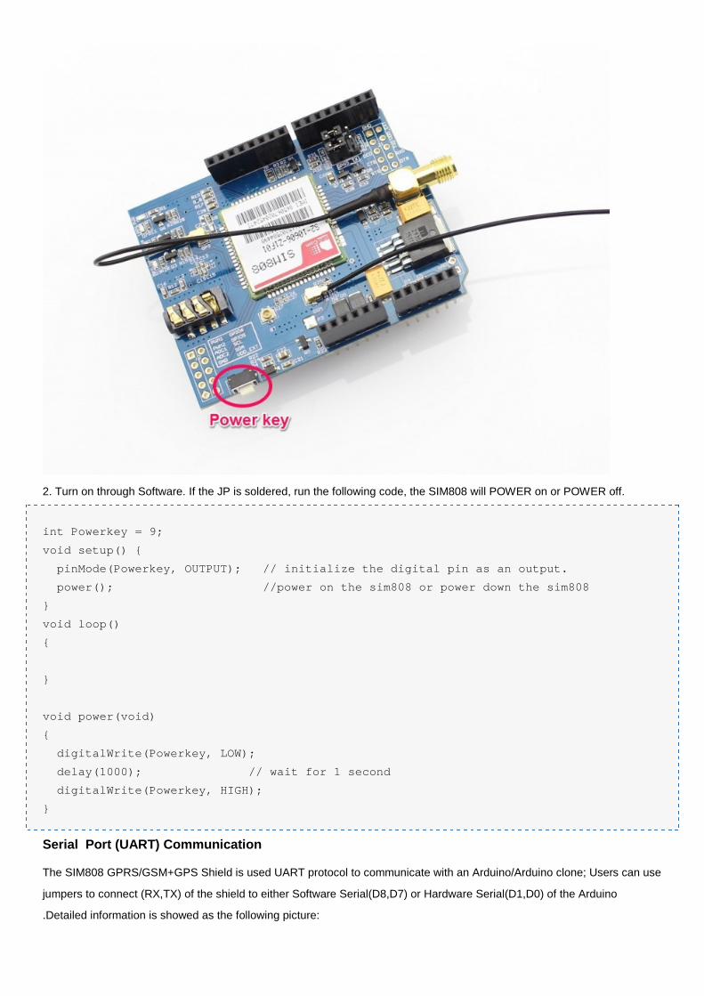
2. Turn on through Software. If the JP is soldered, run the following code, the SIM808 will POWER on or POWER off.
int Powerkey = 9;
void setup() {
pinMode(Powerkey, OUTPUT); // initialize the digital pin as an output.
power(); //power on the sim808 or power down the sim808
}
void loop()
{
}
void power(void)
{
digitalWrite(Powerkey, LOW);
delay(1000); // wait for 1 second
digitalWrite(Powerkey, HIGH);
}
Serial Port (UART) Communication
The SIM808 GPRS/GSM+GPS Shield is used UART protocol to communicate with an Arduino/Arduino clone; Users can use
jumpers to connect (RX,TX) of the shield to either Software Serial(D8,D7) or Hardware Serial(D1,D0) of the Arduino
.Detailed information is showed as the following picture:
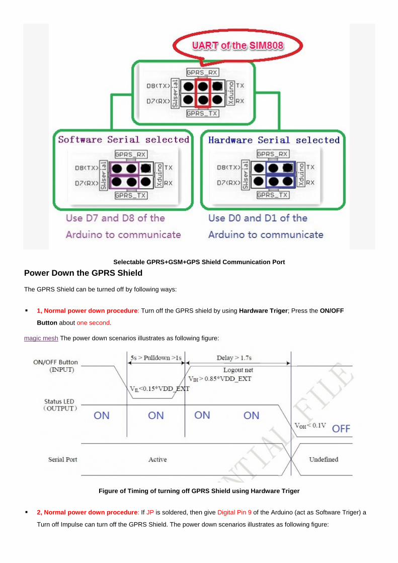
Selectable GPRS+GSM+GPS Shield Communication Port
Power Down the GPRS Shield
The GPRS Shield can be turned off by following ways:
1, Normal power down procedure: Turn off the GPRS shield by using Hardware Triger; Press the ON/OFF
Button about one second.
magic mesh The power down scenarios illustrates as following figure:
Figure of Timing of turning off GPRS Shield using Hardware Triger
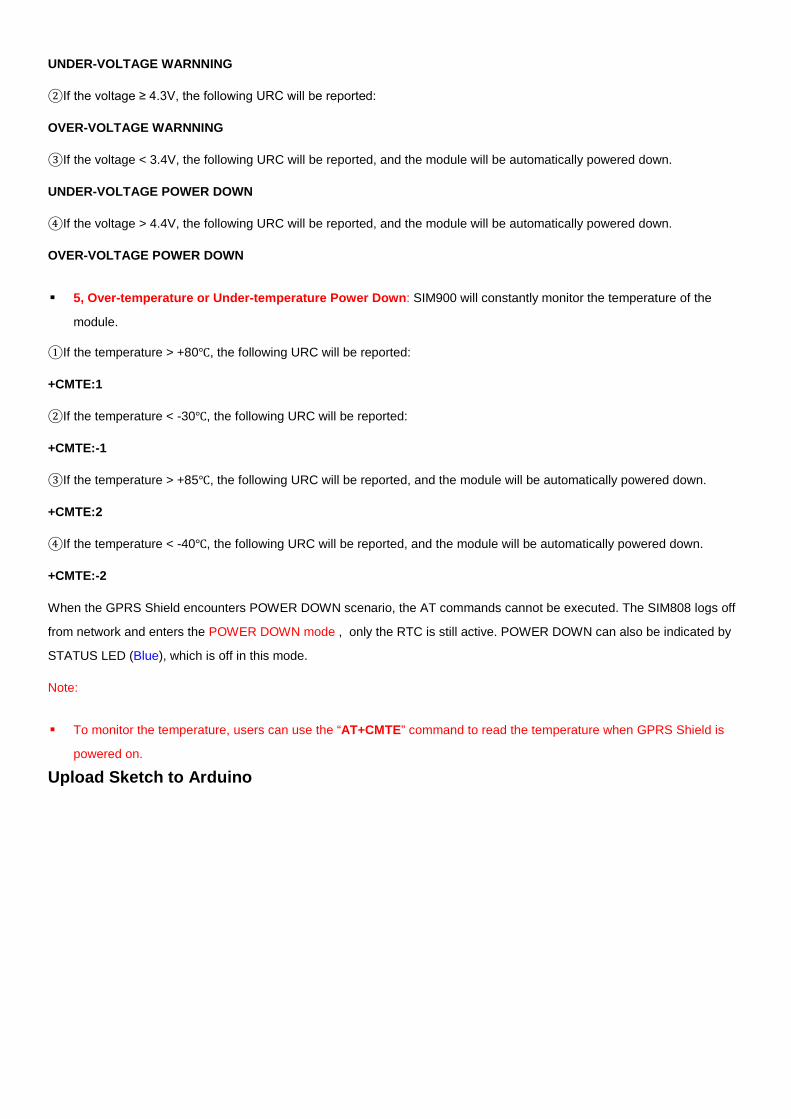
2, Normal power down procedure: If JP is soldered, then give Digital Pin 9 of the Arduino (act as Software Triger) a
Turn off Impulse can turn off the GPRS Shield. The power down scenarios illustrates as following figure:
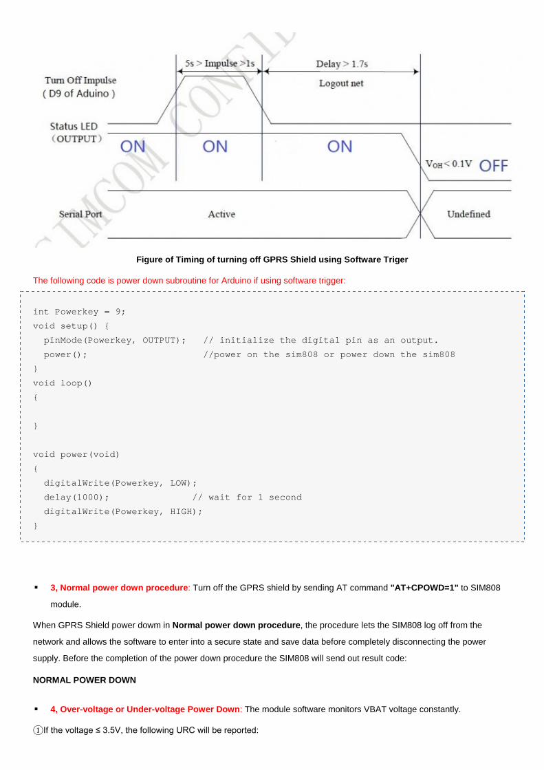
Figure of Timing of turning off GPRS Shield using Software Triger
The following code is power down subroutine for Arduino if using software trigger:
int Powerkey = 9;
void setup() {
pinMode(Powerkey, OUTPUT); // initialize the digital pin as an output.
power(); //power on the sim808 or power down the sim808
}
void loop()
{
}
void power(void)
{
digitalWrite(Powerkey, LOW);
delay(1000); // wait for 1 second
digitalWrite(Powerkey, HIGH);
}
3, Normal power down procedure: Turn off the GPRS shield by sending AT command "AT+CPOWD=1" to SIM808
module.
When GPRS Shield power dowm in Normal power down procedure, the procedure lets the SIM808 log off from the
network and allows the software to enter into a secure state and save data before completely disconnecting the power
supply. Before the completion of the power down procedure the SIM808 will send out result code:
NORMAL POWER DOWN
4, Over-voltage or Under-voltage Power Down: The module software monitors VBAT voltage constantly.
①If the voltage ≤ 3.5V, the following URC will be reported:
UNDER-VOLTAGE WARNNING
②If the voltage ≥ 4.3V, the following URC will be reported:
OVER-VOLTAGE WARNNING
③If the voltage < 3.4V, the following URC will be reported, and the module will be automatically powered down.
UNDER-VOLTAGE POWER DOWN
④If the voltage > 4.4V, the following URC will be reported, and the module will be automatically powered down.
OVER-VOLTAGE POWER DOWN
5, Over-temperature or Under-temperature Power Down: SIM900 will constantly monitor the temperature of the
module.
①If the temperature > +80℃, the following URC will be reported:
+CMTE:1
②If the temperature < -30℃, the following URC will be reported:
+CMTE:-1
③If the temperature > +85℃, the following URC will be reported, and the module will be automatically powered down.
+CMTE:2
④If the temperature < -40℃, the following URC will be reported, and the module will be automatically powered down.
+CMTE:-2
When the GPRS Shield encounters POWER DOWN scenario, the AT commands cannot be executed. The SIM808 logs off
from network and enters the POWER DOWN mode , only the RTC is still active. POWER DOWN can also be indicated by
STATUS LED (Blue), which is off in this mode.
Note:
To monitor the temperature, users can use the “AT+CMTE” command to read the temperature when GPRS Shield is
powered on.
Upload Sketch to Arduino
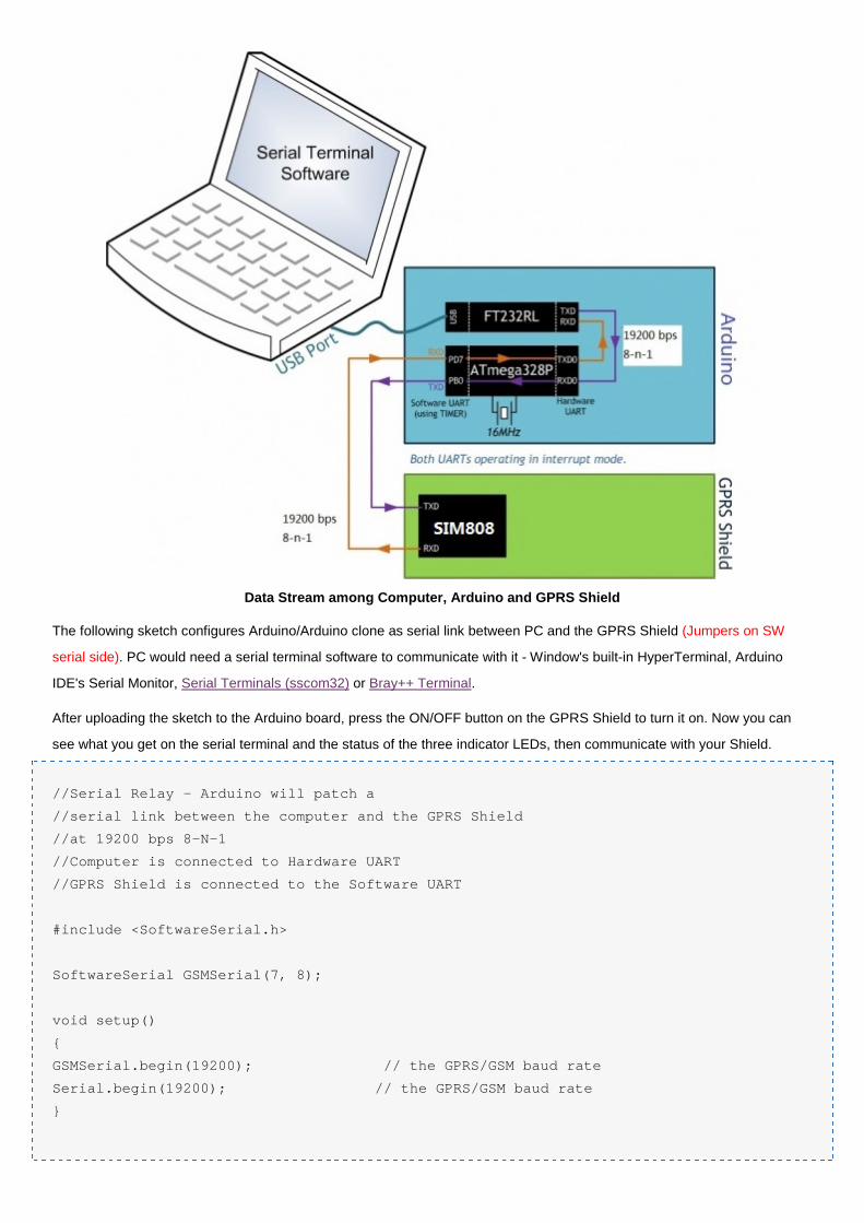
Data Stream among Computer, Arduino and GPRS Shield
The following sketch configures Arduino/Arduino clone as serial link between PC and the GPRS Shield (Jumpers on SW
serial side). PC would need a serial terminal software to communicate with it - Window's built-in HyperTerminal, Arduino
IDE's Serial Monitor, Serial Terminals (sscom32) or Bray++ Terminal.
After uploading the sketch to the Arduino board, press the ON/OFF button on the GPRS Shield to turn it on. Now you can
see what you get on the serial terminal and the status of the three indicator LEDs, then communicate with your Shield.
//Serial Relay - Arduino will patch a
//serial link between the computer and the GPRS Shield
//at 19200 bps 8-N-1
//Computer is connected to Hardware UART
//GPRS Shield is connected to the Software UART
#include <SoftwareSerial.h>
SoftwareSerial GSMSerial(7, 8);
void setup()
{
GSMSerial.begin(19200); // the GPRS/GSM baud rate
Serial.begin(19200); // the GPRS/GSM baud rate
}
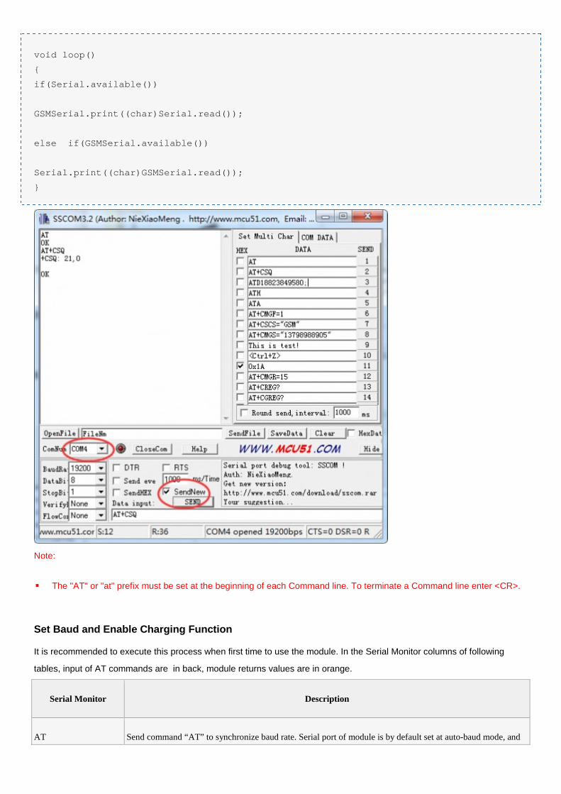
void loop()
{
if(Serial.available())
GSMSerial.print((char)Serial.read());
else if(GSMSerial.available())
Serial.print((char)GSMSerial.read());
}
Note:
The "AT" or "at" prefix must be set at the beginning of each Command line. To terminate a Command line enter <CR>.
Set Baud and Enable Charging Function
It is recommended to execute this process when first time to use the module. In the Serial Monitor columns of following
tables, input of AT commands are in back, module returns values are in orange.
Serial Monitor Description
AT Send command “AT” to synchronize baud rate. Serial port of module is by default set at auto-baud mode, and
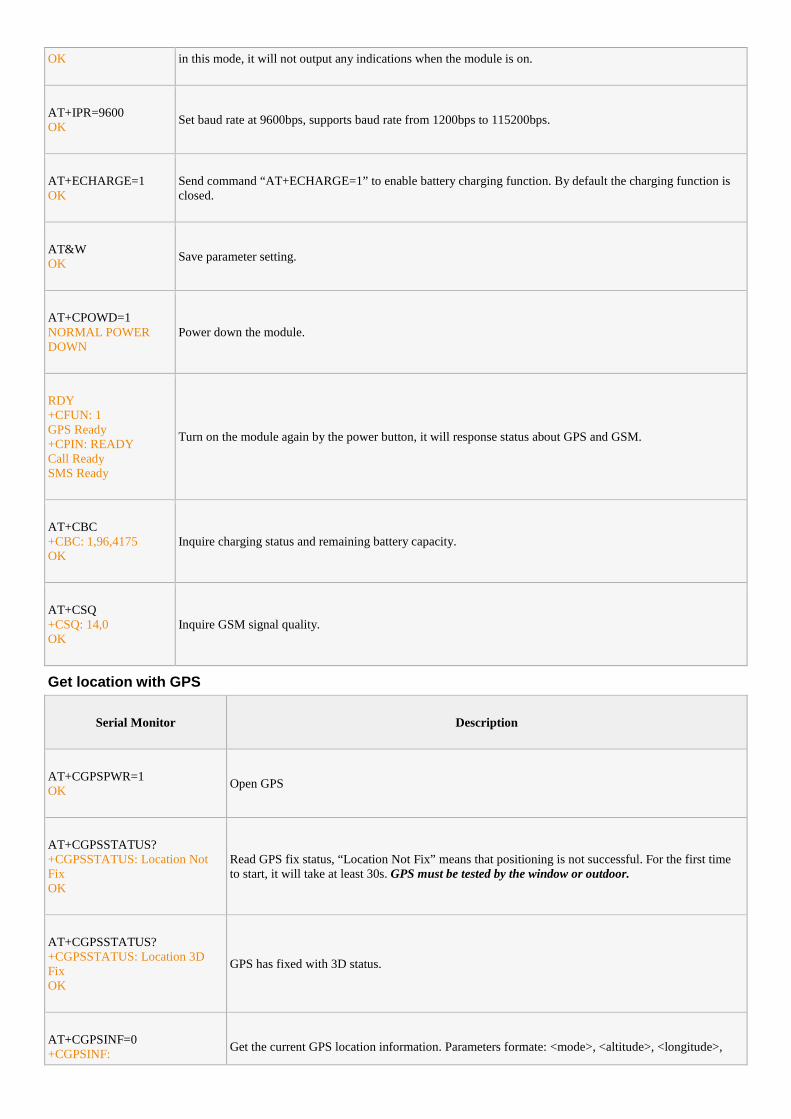
OK in this mode, it will not output any indications when the module is on.
AT+IPR=9600OK
Set baud rate at 9600bps, supports baud rate from 1200bps to 115200bps.
AT+ECHARGE=1OK
Send command “AT+ECHARGE=1” to enable battery charging function. By default the charging function isclosed.
AT&WOK
Save parameter setting.
AT+CPOWD=1NORMAL POWERDOWN
Power down the module.
RDY+CFUN: 1GPS Ready+CPIN: READYCall ReadySMS Ready
Turn on the module again by the power button, it will response status about GPS and GSM.
AT+CBC+CBC: 1,96,4175OK
Inquire charging status and remaining battery capacity.
AT+CSQ+CSQ: 14,0OK
Inquire GSM signal quality.
Get location with GPS
Serial Monitor Description
AT+CGPSPWR=1OK
Open GPS
AT+CGPSSTATUS?+CGPSSTATUS: Location NotFixOK
Read GPS fix status, “Location Not Fix” means that positioning is not successful. For the first timeto start, it will take at least 30s. GPS must be tested by the window or outdoor.
AT+CGPSSTATUS?+CGPSSTATUS: Location 3DFixOK
GPS has fixed with 3D status.
AT+CGPSINF=0+CGPSINF:
Get the current GPS location information. Parameters formate: <mode>, <altitude>, <longitude>,
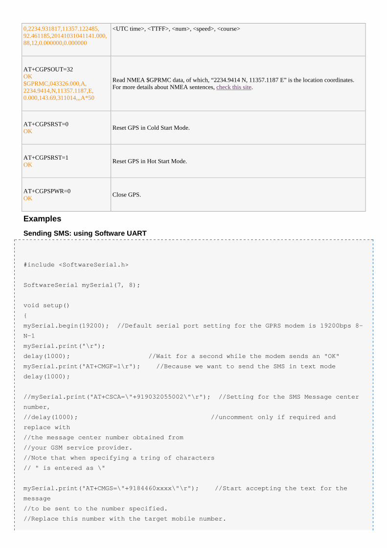
0,2234.931817,11357.122485,92.461185,20141031041141.000,88,12,0.000000,0.000000
<UTC time>, <TTFF>, <num>, <speed>, <course>
AT+CGPSOUT=32OK$GPRMC,043326.000,A,2234.9414,N,11357.1187,E,0.000,143.69,311014,,,A*50
Read NMEA $GPRMC data, of which, “2234.9414 N, 11357.1187 E” is the location coordinates.For more details about NMEA sentences, check this site.
AT+CGPSRST=0OK
Reset GPS in Cold Start Mode.
AT+CGPSRST=1OK
Reset GPS in Hot Start Mode.
AT+CGPSPWR=0OK
Close GPS.
Examples
Sending SMS: using Software UART
#include <SoftwareSerial.h>
SoftwareSerial mySerial(7, 8);
void setup()
{
mySerial.begin(19200); //Default serial port setting for the GPRS modem is 19200bps 8-
N-1
mySerial.print("\r");
delay(1000); //Wait for a second while the modem sends an "OK"
mySerial.print("AT+CMGF=1\r"); //Because we want to send the SMS in text mode
delay(1000);
//mySerial.print("AT+CSCA=\"+919032055002\"\r"); //Setting for the SMS Message center
number,
//delay(1000); //uncomment only if required and
replace with
//the message center number obtained from
//your GSM service provider.
//Note that when specifying a tring of characters
// " is entered as \"
mySerial.print("AT+CMGS=\"+9184460xxxx\"\r"); //Start accepting the text for the
message
//to be sent to the number specified.
//Replace this number with the target mobile number.
delay(1000);
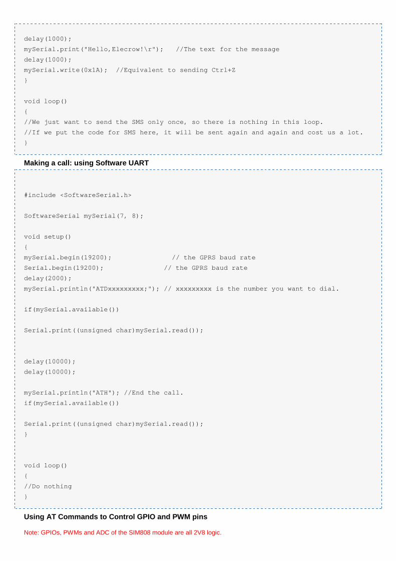
mySerial.print("Hello,Elecrow!\r"); //The text for the message
delay(1000);
mySerial.write(0x1A); //Equivalent to sending Ctrl+Z
}
void loop()
{
//We just want to send the SMS only once, so there is nothing in this loop.
//If we put the code for SMS here, it will be sent again and again and cost us a lot.
}
Making a call: using Software UART
#include <SoftwareSerial.h>
SoftwareSerial mySerial(7, 8);
void setup()
{
mySerial.begin(19200); // the GPRS baud rate
Serial.begin(19200); // the GPRS baud rate
delay(2000);
mySerial.println("ATDxxxxxxxxx;"); // xxxxxxxxx is the number you want to dial.
if(mySerial.available())
Serial.print((unsigned char)mySerial.read());
delay(10000);
delay(10000);
mySerial.println("ATH"); //End the call.
if(mySerial.available())
Serial.print((unsigned char)mySerial.read());
}
void loop()
{
//Do nothing
}
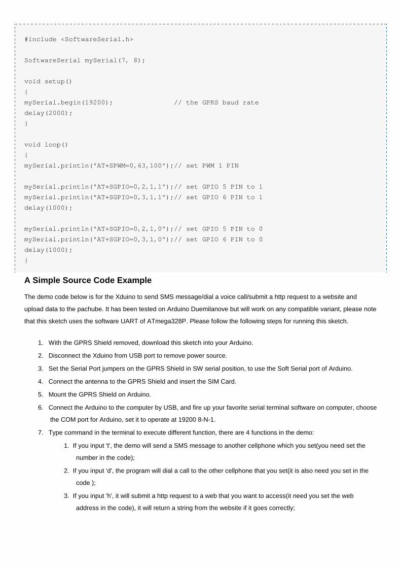
Using AT Commands to Control GPIO and PWM pins
Note: GPIOs, PWMs and ADC of the SIM808 module are all 2V8 logic.
#include <SoftwareSerial.h>
SoftwareSerial mySerial(7, 8);
void setup()
{
mySerial.begin(19200); // the GPRS baud rate
delay(2000);
}
void loop()
{
mySerial.println("AT+SPWM=0,63,100");// set PWM 1 PIN
mySerial.println("AT+SGPIO=0,2,1,1");// set GPIO 5 PIN to 1
mySerial.println("AT+SGPIO=0,3,1,1");// set GPIO 6 PIN to 1
delay(1000);
mySerial.println("AT+SGPIO=0,2,1,0");// set GPIO 5 PIN to 0
mySerial.println("AT+SGPIO=0,3,1,0");// set GPIO 6 PIN to 0
delay(1000);
}
A Simple Source Code Example
The demo code below is for the Xduino to send SMS message/dial a voice call/submit a http request to a website and
upload data to the pachube. It has been tested on Arduino Duemilanove but will work on any compatible variant, please note
that this sketch uses the software UART of ATmega328P. Please follow the following steps for running this sketch.
1. With the GPRS Shield removed, download this sketch into your Arduino.
2. Disconnect the Xduino from USB port to remove power source.
3. Set the Serial Port jumpers on the GPRS Shield in SW serial position, to use the Soft Serial port of Arduino.
4. Connect the antenna to the GPRS Shield and insert the SIM Card.
5. Mount the GPRS Shield on Arduino.
6. Connect the Arduino to the computer by USB, and fire up your favorite serial terminal software on computer, choose
the COM port for Arduino, set it to operate at 19200 8-N-1.
7. Type command in the terminal to execute different function, there are 4 functions in the demo:
1. If you input 't', the demo will send a SMS message to another cellphone which you set(you need set the
number in the code);
2. If you input 'd', the program will dial a call to the other cellphone that you set(it is also need you set in the
code );
3. If you input 'h', it will submit a http request to a web that you want to access(it need you set the web
address in the code), it will return a string from the website if it goes correctly;
4. If you input 's', it will upload the data to the pachube(for detail you can refer to the explanation in the code).
I strongly recommend you input 'h' before input 's', because uploading data to the pachube need do some
setting, after execute the function of submit a http request, the setting will be set.
8. If the program returns error in the terminal after you typed the command, don't worry, just try to input the command
again.
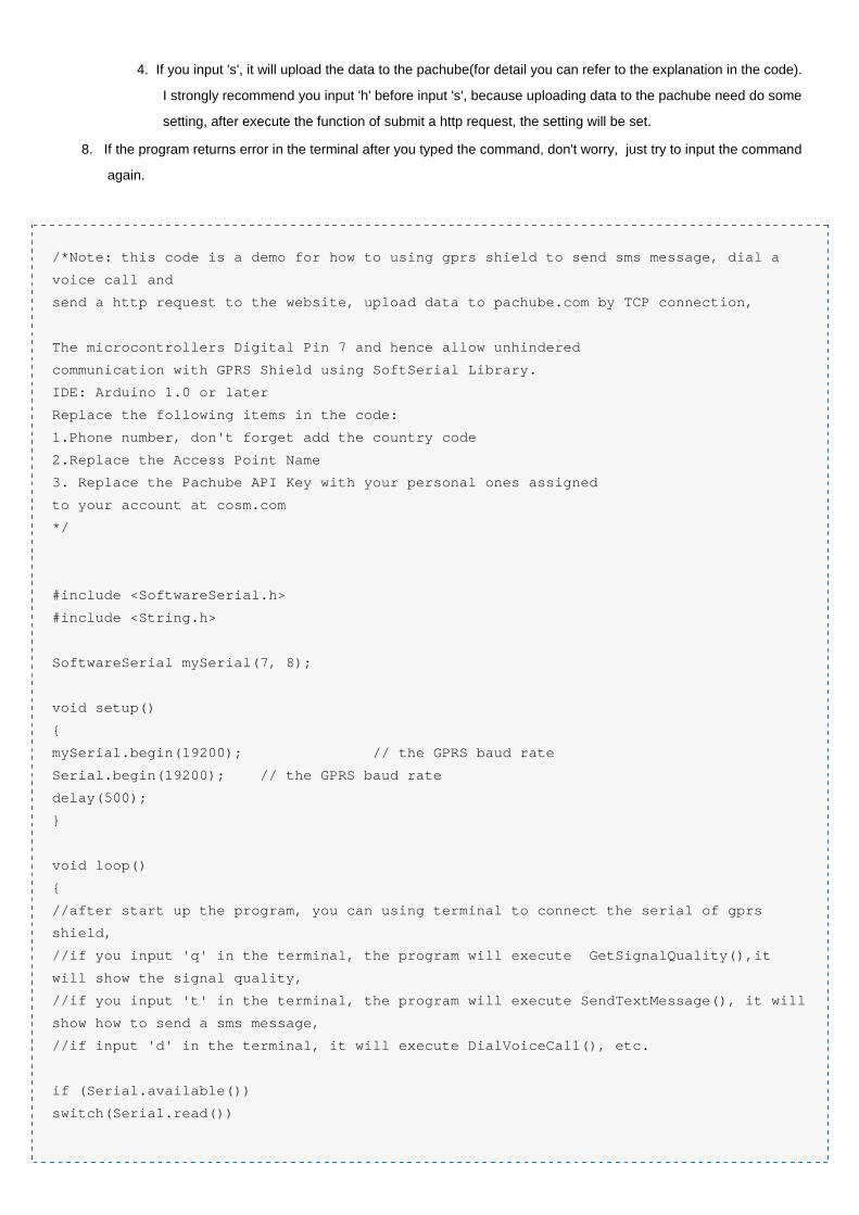
/*Note: this code is a demo for how to using gprs shield to send sms message, dial a
voice call and
send a http request to the website, upload data to pachube.com by TCP connection,
The microcontrollers Digital Pin 7 and hence allow unhindered
communication with GPRS Shield using SoftSerial Library.
IDE: Arduino 1.0 or later
Replace the following items in the code:
1.Phone number, don't forget add the country code
2.Replace the Access Point Name
3. Replace the Pachube API Key with your personal ones assigned
to your account at cosm.com
*/
#include <SoftwareSerial.h>
#include <String.h>
SoftwareSerial mySerial(7, 8);
void setup()
{
mySerial.begin(19200); // the GPRS baud rate
Serial.begin(19200); // the GPRS baud rate
delay(500);
}
void loop()
{
//after start up the program, you can using terminal to connect the serial of gprs
shield,
//if you input 'q' in the terminal, the program will execute GetSignalQuality(),it
will show the signal quality,
//if you input 't' in the terminal, the program will execute SendTextMessage(), it will
show how to send a sms message,
//if input 'd' in the terminal, it will execute DialVoiceCall(), etc.
if (Serial.available())
switch(Serial.read())
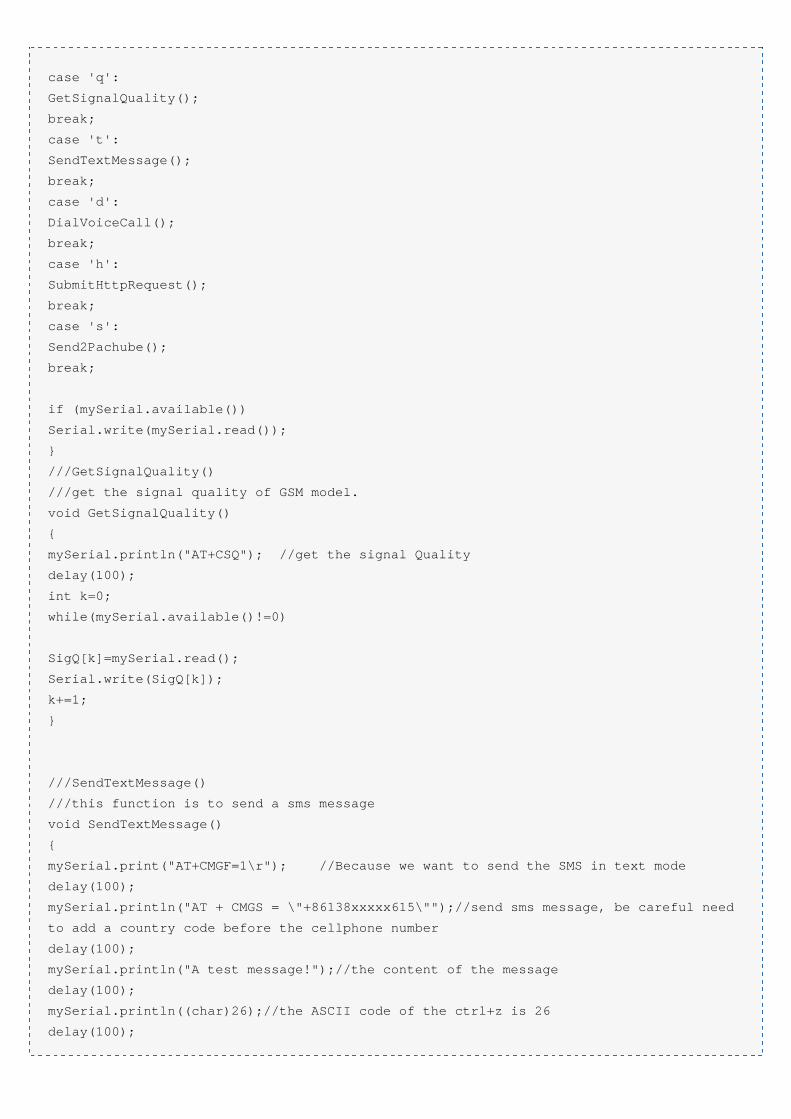
case 'q':
GetSignalQuality();
break;
case 't':
SendTextMessage();
break;
case 'd':
DialVoiceCall();
break;
case 'h':
SubmitHttpRequest();
break;
case 's':
Send2Pachube();
break;
if (mySerial.available())
Serial.write(mySerial.read());
}
///GetSignalQuality()
///get the signal quality of GSM model.
void GetSignalQuality()
{
mySerial.println("AT+CSQ"); //get the signal Quality
delay(100);
int k=0;
while(mySerial.available()!=0)
SigQ[k]=mySerial.read();
Serial.write(SigQ[k]);
k+=1;
}
///SendTextMessage()
///this function is to send a sms message
void SendTextMessage()
{
mySerial.print("AT+CMGF=1\r"); //Because we want to send the SMS in text mode
delay(100);
mySerial.println("AT + CMGS = \"+86138xxxxx615\"");//send sms message, be careful need
to add a country code before the cellphone number
delay(100);
mySerial.println("A test message!");//the content of the message
delay(100);
mySerial.println((char)26);//the ASCII code of the ctrl+z is 26
delay(100);
mySerial.println();
}
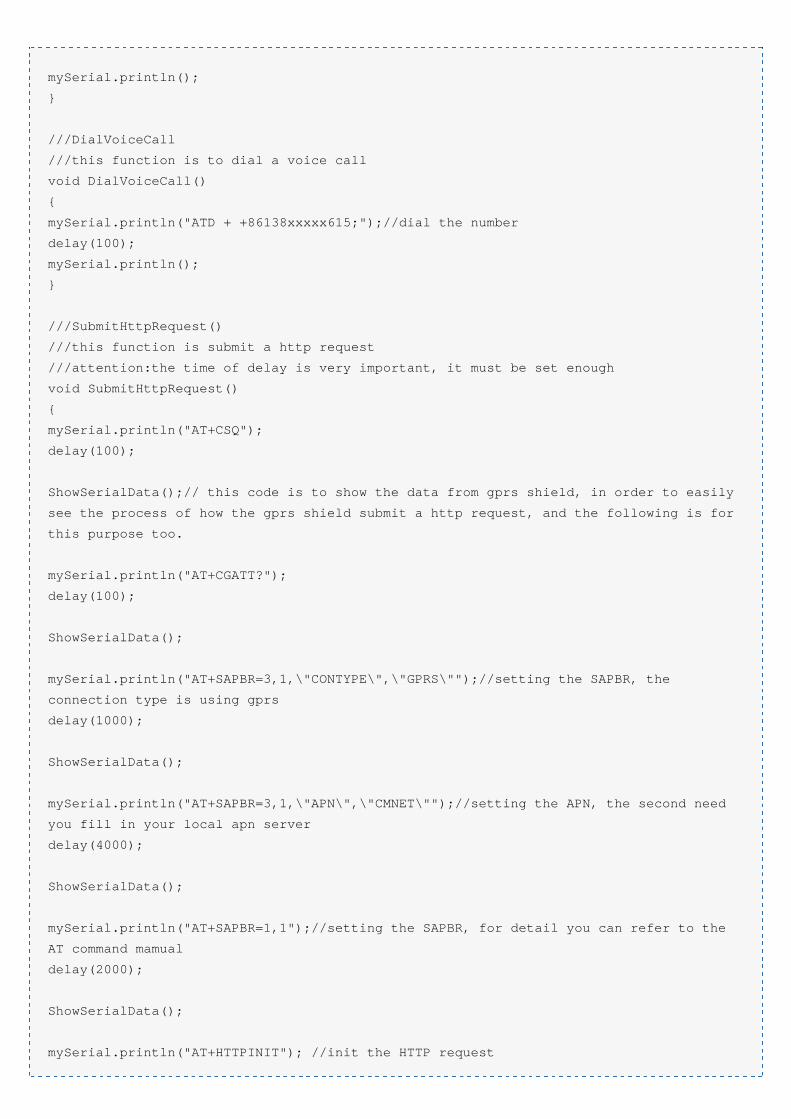
///DialVoiceCall
///this function is to dial a voice call
void DialVoiceCall()
{
mySerial.println("ATD + +86138xxxxx615;");//dial the number
delay(100);
mySerial.println();
}
///SubmitHttpRequest()
///this function is submit a http request
///attention:the time of delay is very important, it must be set enough
void SubmitHttpRequest()
{
mySerial.println("AT+CSQ");
delay(100);
ShowSerialData();// this code is to show the data from gprs shield, in order to easily
see the process of how the gprs shield submit a http request, and the following is for
this purpose too.
mySerial.println("AT+CGATT?");
delay(100);
ShowSerialData();
mySerial.println("AT+SAPBR=3,1,\"CONTYPE\",\"GPRS\"");//setting the SAPBR, the
connection type is using gprs
delay(1000);
ShowSerialData();
mySerial.println("AT+SAPBR=3,1,\"APN\",\"CMNET\"");//setting the APN, the second need
you fill in your local apn server
delay(4000);
ShowSerialData();
mySerial.println("AT+SAPBR=1,1");//setting the SAPBR, for detail you can refer to the
AT command mamual
delay(2000);
ShowSerialData();
mySerial.println("AT+HTTPINIT"); //init the HTTP request
delay(2000);
ShowSerialData();
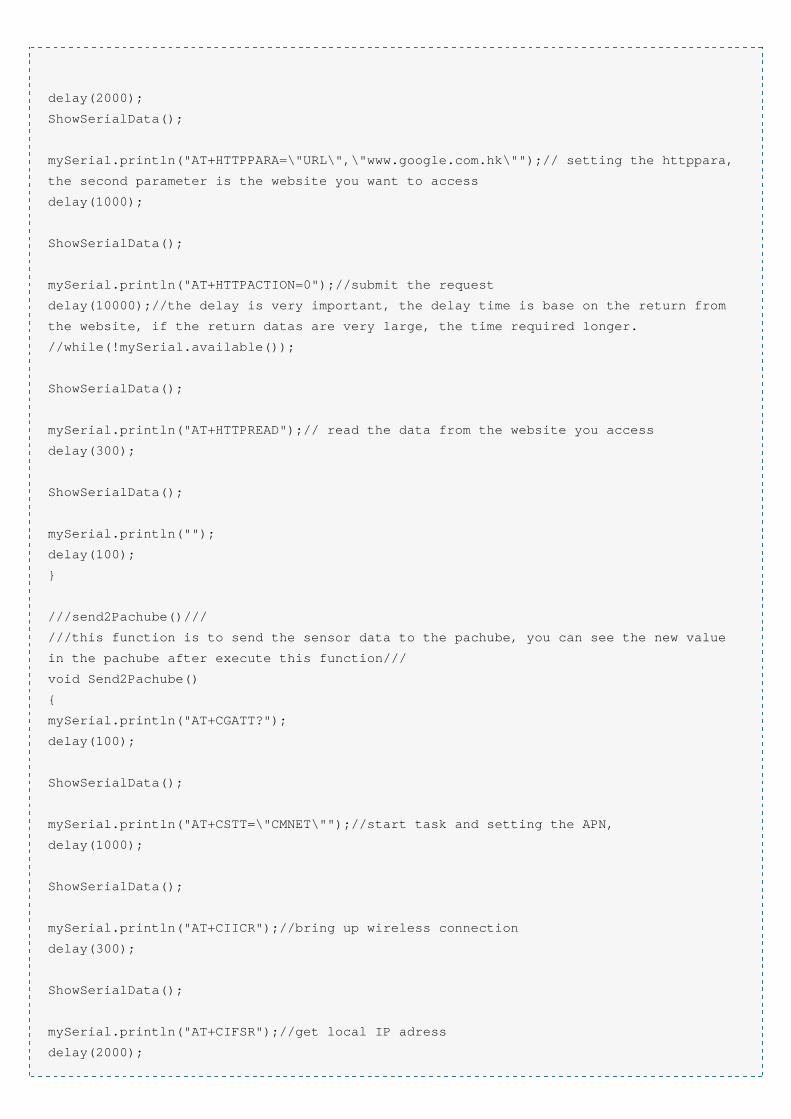
mySerial.println("AT+HTTPPARA=\"URL\",\"www.google.com.hk\"");// setting the httppara,
the second parameter is the website you want to access
delay(1000);
ShowSerialData();
mySerial.println("AT+HTTPACTION=0");//submit the request
delay(10000);//the delay is very important, the delay time is base on the return from
the website, if the return datas are very large, the time required longer.
//while(!mySerial.available());
ShowSerialData();
mySerial.println("AT+HTTPREAD");// read the data from the website you access
delay(300);
ShowSerialData();
mySerial.println("");
delay(100);
}
///send2Pachube()///
///this function is to send the sensor data to the pachube, you can see the new value
in the pachube after execute this function///
void Send2Pachube()
{
mySerial.println("AT+CGATT?");
delay(100);
ShowSerialData();
mySerial.println("AT+CSTT=\"CMNET\"");//start task and setting the APN,
delay(1000);
ShowSerialData();
mySerial.println("AT+CIICR");//bring up wireless connection
delay(300);
ShowSerialData();
mySerial.println("AT+CIFSR");//get local IP adress
delay(2000);
ShowSerialData();
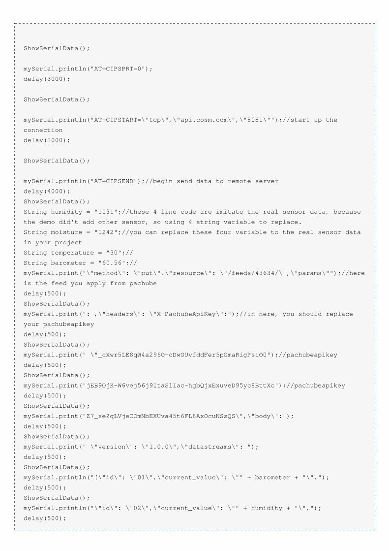
mySerial.println("AT+CIPSPRT=0");
delay(3000);
ShowSerialData();
mySerial.println("AT+CIPSTART=\"tcp\",\"api.cosm.com\",\"8081\"");//start up the
connection
delay(2000);
ShowSerialData();
mySerial.println("AT+CIPSEND");//begin send data to remote server
delay(4000);
ShowSerialData();
String humidity = "1031";//these 4 line code are imitate the real sensor data, because
the demo did't add other sensor, so using 4 string variable to replace.
String moisture = "1242";//you can replace these four variable to the real sensor data
in your project
String temperature = "30";//
String barometer = "60.56";//
mySerial.print("\"method\": \"put\",\"resource\": \"/feeds/43634/\",\"params\"");//here
is the feed you apply from pachube
delay(500);
ShowSerialData();
mySerial.print(": ,\"headers\": \"X-PachubeApiKey\":");//in here, you should replace
your pachubeapikey
delay(500);
ShowSerialData();
mySerial.print(" \"_cXwr5LE8qW4a296O-cDwOUvfddFer5pGmaRigPsiO0");//pachubeapikey
delay(500);
ShowSerialData();
mySerial.print("jEB9OjK-W6vej56j9ItaSlIac-hgbQjxExuveD95yc8BttXc");//pachubeapikey
delay(500);
ShowSerialData();
mySerial.print("Z7_seZqLVjeCOmNbEXUva45t6FL8AxOcuNSsQS\",\"body\":");
delay(500);
ShowSerialData();
mySerial.print(" \"version\": \"1.0.0\",\"datastreams\": ");
delay(500);
ShowSerialData();
mySerial.println("[\"id\": \"01\",\"current_value\": \"" + barometer + "\",");
delay(500);
ShowSerialData();
mySerial.println("\"id\": \"02\",\"current_value\": \"" + humidity + "\",");
delay(500);
ShowSerialData();
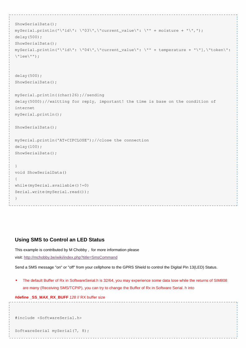
mySerial.println("\"id\": \"03\",\"current_value\": \"" + moisture + "\",");
delay(500);
ShowSerialData();
mySerial.println("\"id\": \"04\",\"current_value\": \"" + temperature + "\"],\"token\":
\"lee\"");
delay(500);
ShowSerialData();
mySerial.println((char)26);//sending
delay(5000);//waitting for reply, important! the time is base on the condition of
internet
mySerial.println();
ShowSerialData();
mySerial.println("AT+CIPCLOSE");//close the connection
delay(100);
ShowSerialData();
}
void ShowSerialData()
{
while(mySerial.available()!=0)
Serial.write(mySerial.read());
}
Using SMS to Control an LED Status
This example is contributed by M Chobby , for more information please
visit: http://mchobby.be/wiki/index.php?title=SmsCommand
Send a SMS message "on" or "off" from your cellphone to the GPRS Shield to control the Digital Pin 13(LED) Status.
The default Buffer of Rx in SoftwareSerial.h is 32/64, you may experience some data lose while the returns of SIM808
are many (Receiving SMS/TCPIP), you can try to change the Buffer of Rx in Software Serial. h into
#define _SS_MAX_RX_BUFF 128 // RX buffer size
#include <SoftwareSerial.h>
SoftwareSerial mySerial(7, 8);
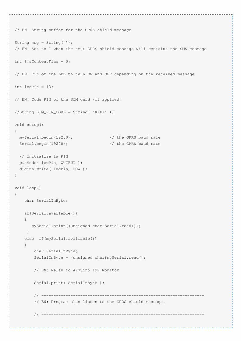
// EN: String buffer for the GPRS shield message
String msg = String("");
// EN: Set to 1 when the next GPRS shield message will contains the SMS message
int SmsContentFlag = 0;
// EN: Pin of the LED to turn ON and OFF depending on the received message
int ledPin = 13;
// EN: Code PIN of the SIM card (if applied)
//String SIM_PIN_CODE = String( "XXXX" );
void setup()
{
mySerial.begin(19200); // the GPRS baud rate
Serial.begin(19200); // the GPRS baud rate
// Initialize la PIN
pinMode( ledPin, OUTPUT );
digitalWrite( ledPin, LOW );
}
void loop()
{
char SerialInByte;
if(Serial.available())
{
mySerial.print((unsigned char)Serial.read());
}
else if(mySerial.available())
{
char SerialInByte;
SerialInByte = (unsigned char)mySerial.read();
// EN: Relay to Arduino IDE Monitor
Serial.print( SerialInByte );
// -------------------------------------------------------------------
// EN: Program also listen to the GPRS shield message.
// -------------------------------------------------------------------
// EN: If the message ends with <CR> then process the message
if( SerialInByte == 13 ){
// EN: Store the char into the message buffer
ProcessGprsMsg();
}
if( SerialInByte == 10 ){
// EN: Skip Line feed
}
else {
// EN: store the current character in the message string buffer
msg += String(SerialInByte);
}
}
}
// EN: Make action based on the content of the SMS.
// Notice than SMS content is the result of the processing of several GPRS shield
messages.
void ProcessSms( String sms ){
Serial.print( "ProcessSms for [" );
Serial.print( sms );
Serial.println( "]" );
if( sms.indexOf("on") >= 0 ){
digitalWrite( ledPin, HIGH );
Serial.println( "LED IS ON" );
return;
}
if( sms.indexOf("off") >= 0 ){
digitalWrite( ledPin, LOW );
Serial.println( "LED IS OFF" );
return;
}
}
// EN: Send the SIM PIN Code to the GPRS shield
//void GprsSendPinCode(){
// if( SIM_PIN_CODE.indexOf("XXXX")>=0 ){
// Serial.println( "*** OUPS! you did not have provided a PIN CODE for your SIM
CARD. ***" );
// Serial.println( "*** Please, define the SIM_PIN_CODE variable . ***" );
// return;
// }
// mySerial.print("AT+CPIN=");
// mySerial.println( SIM_PIN_CODE );
}
// EN: Request Text Mode for SMS messaging
void GprsTextModeSMS(){
mySerial.println( "AT+CMGF=1" );
}
void GprsReadSmsStore( String SmsStorePos ){
// Serial.print( "GprsReadSmsStore for storePos " );
// Serial.println( SmsStorePos );
mySerial.print( "AT+CMGR=" );
mySerial.println( SmsStorePos );
}
// EN: Clear the GPRS shield message buffer
void ClearGprsMsg(){
msg = "";
}
// EN: interpret the GPRS shield message and act appropiately
void ProcessGprsMsg() {
Serial.println("");
Serial.print( "GPRS Message: [" );
Serial.print( msg );
Serial.println( "]" );
// if( msg.indexOf( "+CPIN: SIM PIN" ) >= 0 ){
// Serial.println( "*** NEED FOR SIM PIN CODE ***" );
// Serial.println( "PIN CODE *** WILL BE SEND NOW" );
// GprsSendPinCode();
// }
if( msg.indexOf( "Call Ready" ) >= 0 ){
Serial.println( "*** GPRS Shield registered on Mobile Network ***" );
GprsTextModeSMS();
}
// EN: unsolicited message received when getting a SMS message
// FR: Message non sollicité quand un SMS arrive
if( msg.indexOf( "+CMTI" ) >= 0 ){
Serial.println( "*** SMS Received ***" );
// EN: Look for the coma in the full message (+CMTI: "SM",6)
// In the sample, the SMS is stored at position 6
int iPos = msg.indexOf( "," );
String SmsStorePos = msg.substring( iPos+1 );
Serial.print( "SMS stored at " );
Serial.println( SmsStorePos );
// EN: Ask to read the SMS store
GprsReadSmsStore( SmsStorePos );
}
// EN: SMS store readed through UART (result of GprsReadSmsStore request)
if( msg.indexOf( "+CMGR:" ) >= 0 ){
// EN: Next message will contains the BODY of SMS
SmsContentFlag = 1;
// EN: Following lines are essentiel to not clear the flag!
ClearGprsMsg();
return;
}
// EN: +CMGR message just before indicate that the following GRPS Shield message
// (this message) will contains the SMS body
if( SmsContentFlag == 1 ){
Serial.println( "*** SMS MESSAGE CONTENT ***" );
Serial.println( msg );
Serial.println( "*** END OF SMS MESSAGE ***" );
ProcessSms( msg );
}
ClearGprsMsg();
// EN: Always clear the flag
SmsContentFlag = 0;
}
Print the GPS data with serial port
Note : The below usage just suitable for the SIM808 GPRS/GSM+GPS Shield v1.1,because the main IC SIM808 was the
new version:S2-1060C-21F02.