Embed Size (px)
Citation preview
School of Engineering Science Simon Fraser University
Burnaby, BC V5A 1S6 [email protected]
November 4th, 2012
Dr. Andrew Rawicz
School of Engineering Science
Simon Fraser University
Burnaby, British Columbia
V5A 1S6
Re: ENSC 440/305W Design Specification for a Mobile Medication Alert System (MMAS)
Dear Dr. Rawicz:
Enclosed is the design specification for our device, the Mobile Medication Alert System
(MMAS), which outlines our Engineering Science 440 Capstone Project. We plan to build, a
medical alert system which will physically keep track of a user’s pills and alert them and
their designated loved one/caregiver through a smart phone application when they have
forgotten or improperly taken their pills.
Our design specification provides the detailed design requirements by breaking down our
project into 3 components: microprocessor,server and mobile application. Each section will
describe the detail of high level functional requirements of its given components, including
integration with other components.
SmartMed Incorporated consists of five motivated, innovative, and talented 5th-year
engineering students: Li Xiang, Kevin Wang, Steven Verner, Fan Yang and Freda Feng. If
you have any questions or concerns about our proposal, please feel free to contact us by
phone at 778-882-9418 or by e-mail at [email protected].
Sincerely,
Fan Yang
Chief Executive Officer
SmartMed Incorporated
Enclosed: Mobile Medical Alert System Design Specification
Design Specification For the Mobile Medication Alert System
Copyright © 2012, SmartMed Incorporated Page 2
Mobile Medication
Alert System
Design Specification
Project Team: Steven Verner
Kevin Wang
Xue Feng
Li Xiang
Fan Yang
Contact Person: Fan Yang
Submitted to: Dr.Andrew Rawicz – ENSC440
Steve Whitmore – ENSC305
School of Engineering Science
Simon Fraser University
Issued date: November 4th, 2012
Design Specification For the Mobile Medication Alert System
Copyright © 2012, SmartMed Incorporated Page 3
Executive Summary
For many people, especially seniors and patients, medications not only can be a salvation of
life and health, but also a disaster waiting to happen. The consequence would perhaps be
deadly if doses of medication are skipped, or too much medication is taken. “55 percent of
the elderly are "non-compliant" with their prescription drugs orders, meaning they don't take
the medication according to the doctor's orders. Approximately 200,000 older adults are
hospitalized annually due to adverse drug reactions.” [1] There are many reasons cause
people forget or mistake their medications such as vision problem of seniors, memory loss of
psychopaths or even just busy work.
To solve this problem, our company is developing a simple, easy-to-use, inexpensive device
Mobile Medication Alert System (MMAS) to physically checks that the user has taken the
correct pills for the current day on time and in the case of forgotten or mistaken pills, the user
will be alerted first and if they have no responding, the alert message will send to the second
person who take care of the user through their smart phones automatically.
This document outlines detailed specifications for the designing and implementing of the
prototype model of the MMAS by breaking it down into 3 main components: microprocessor
bundled with WIFI shield and sensors, server and mobile application. The design model,
operation flowcharts, data analysis, software interface, test plans and testing parameters are
also described in detail in this document.
Design Specification For the Mobile Medication Alert System
Copyright © 2012, SmartMed Incorporated Page 4
Table of Contents Executive Summary ................................................................................................................... 3
List of Figures ............................................................................................................................ 6
List of Tables ............................................................................................................................. 6
Glossary ..................................................................................................................................... 7
1. Introduction............................................................................................................................ 8
1.1 Scope............................................................................................................................ 8
1.2 Intended Audience ....................................................................................................... 8
2 System Specifications ............................................................................................................. 8
3 Overall System Design ........................................................................................................... 9
3.1 Mechanical Design ...................................................................................................... 9
3.2 High-level System Design ......................................................................................... 11
3.3 Sensors and LEDs placement .................................................................................... 12
3.4 Safety and Environmental Protection considerations ................................................ 14
4 Mobile App Overview .......................................................................................................... 14
4.1 Mobile App Interface Design .................................................................................... 15
4.2 Mobile App System Design ....................................................................................... 17
4.3 Server Overview ........................................................................................................ 18
5 Low-Level System Design ................................................................................................... 20
5.1 Overview of the system components ......................................................................... 20
5.2 Arduino Mega 2560 Microcontroller ......................................................................... 21
5.3 Linksprite WIFI Shield .............................................................................................. 23
5.4 Interlink Electronics Force sensor ............................................................................. 24
5.4.1 The Circuit of Force Sensor .................................................................................... 24
5.5 LED Lights ................................................................................................................ 25
5.5.1 The Circuit of LEDs ............................................................................................... 26
Design Specification For the Mobile Medication Alert System
Copyright © 2012, SmartMed Incorporated Page 5
5.6 Power Supply Requirements ...................................................................................... 26
5.7 Signal Processing on Microcontroller ....................................................................... 26
5.8 Data format in communication .................................................................................. 28
5.8.1 Receive from Server ............................................................................................... 28
5.8.2 Post to Server .......................................................................................................... 28
6 User Interface Unit ............................................................................................................... 29
6.1 User Interface Hardware ............................................................................................ 29
6.2 User Interface Software ............................................................................................. 30
6.2.1 Registration Screen ................................................................................................. 30
6.2.2 Main Screen for Primary or Secondary User .......................................................... 30
6.2.3 Alert Message for Primary or Secondary User ....................................................... 30
6.2.4 Time Schedule for Primary or Secondary User ...................................................... 30
6.2.5 Interface for Doctors ............................................................................................... 30
6.3 User Interface Verification ........................................................................................ 30
7 System Test Plan ................................................................................................................... 31
7.1 Unit Testing ............................................................................................................... 31
7.2 System Testing ........................................................................................................... 32
7.2.1 Normal Case 1: Notification for Taking Pills on Time .......................................... 32
7.2.2 Normal Case 2: Notification for Forgotten to Taking Pills .................................... 32
7.2.3 Normal Case 3: Notification for Taking Wrong Pills ............................................. 32
7.2.4 Normal Case 4: Notification for No Response by User.......................................... 32
7.2.5 Extreme Case 1: No Power for Pillbox and WI-FI Shield ...................................... 33
7.3 User System Testing .................................................................................................. 33
8 Conclusion ............................................................................................................................ 33
9 Reference .............................................................................................................................. 34
Design Specification For the Mobile Medication Alert System
Copyright © 2012, SmartMed Incorporated Page 6
List of Figures
Figure 1: System Function Block Diagram
Figure 2: Isometric View of Pill Dispenser Box
Figure 3: Isometric View of Top Part and Bottom Part
Figure 4: System Mechanism Diagram
Figure 5: FSR Construction
Figure 6: The Force Sensors and LEDs Assembly Diagram
Figure 7: Interface of iPhone App
Figure 8: App Class Diagram
Figure 9: Server Function Block Diagram
Figure 10: Overall Design of the System
Figure 11: Ardunio Mega 2560 Front View
Figure 12: Atmega2560-Arduino Pin Mapping
Figure 13: LinkSprite Copperhead WIFI Shield
Figure 14: Interlink Electronics FSR 406 43.69 Square Force Sensors
Figure 15: The Circuit of Force Sensor
Figure 16: LEDs
Figure 17: The Circuit of LED Indicators
Figure 18: Flow Chart of the Microprocessor
List of Tables
Table 1: Pin Assignment of the Arduino Mega Board
Table 2: Power Usage in Different Work Modes of WIFI Shield
Design Specification For the Mobile Medication Alert System
Copyright © 2012, SmartMed Incorporated Page 7
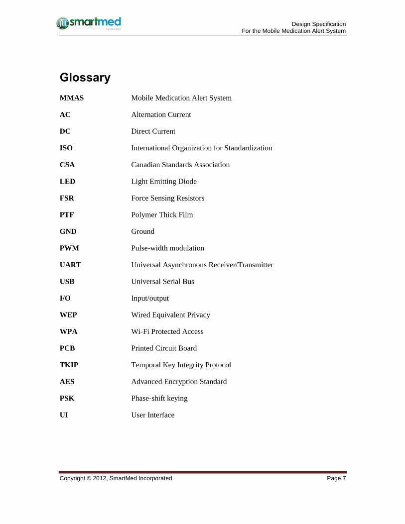
Glossary
MMAS Mobile Medication Alert System
AC Alternation Current
DC Direct Current
ISO International Organization for Standardization
CSA Canadian Standards Association
LED Light Emitting Diode
FSR Force Sensing Resistors
PTF Polymer Thick Film
GND Ground
PWM Pulse-width modulation
UART Universal Asynchronous Receiver/Transmitter
USB Universal Serial Bus
I/O Input/output
WEP Wired Equivalent Privacy
WPA Wi-Fi Protected Access
PCB Printed Circuit Board
TKIP Temporal Key Integrity Protocol
AES Advanced Encryption Standard
PSK Phase-shift keying
UI User Interface
Design Specification For the Mobile Medication Alert System
Copyright © 2012, SmartMed Incorporated Page 8
1. Introduction
In order to solve the problem for seniors and patients who sometimes might forget to taking
pills or accidently take the wrong pills, SmartMed Incorporated is planning to build a system,
Mobile Medication Alert System (MMAS), which will keep track of a user’s pills and will
alert the user when he or she has forgotten to take pills or taken the wrong pills by accident.
User will receive a message from the IPhone App when it is time to take pills. If the user has
forgotten to take pills on time or taken the wrong pills, the force sensors under the pill box
will physically detect it and send signals to the microcontroller who will process these signals
and send the result to IPhone App through a server using WIFI Shield. After that, user will
receive another notification about it. However, if the user doesn’t response the notification, a
second alert will send to user’s designated loved one or caregiver one hour later. This design
specification describes the technical details for the design of each component of the Mobile
Medication Alert System (MMAS).
1.1 Scope
This document specifies the design of the Mobile Medication Alert System (MMAS) and
explains how the design meets the functional requirements as described in Functional
Specification for a Mobile Medication Alert System (MMAS). The design specification
includes all requirements for a proof-of-concept system and a partial set of requirements for
the final production model. It describes the operation flowcharts, test plans, test parameters,
data analysis, user interface and SolidWorks design model in details.
1.2 Intended Audience
This design specification is intended for use by the member of SmartMed Incorporated and
all others who may become involved in constructing the MMAS proof of concept product.
We shall refer to these specifications as general design guidelines during the prototype design
phase and use this document to implement the test plan during the building phase of MMAS.
2 System Specifications
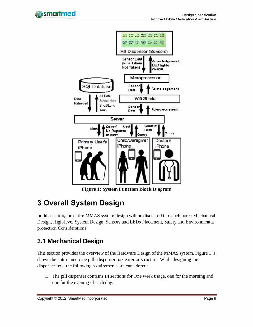
The MMAS System will help users to take the medicine pills on time for each day according
to the schedule set by users. The system includes hardware: Dispenser Box, microcontroller
and Software: IPhone App and its own server. The MMAS system generates an Alert to the
main user’s smart phone when they have failed to remove pills from the Dispenser Box with
in the 15 mins of the scheduled time. It will also generate a secondary alert to other
designated iPhones if no response from the mobile end and pills are still not taken between
15 mins and 30 mins of the scheduled time. In the meantime, it records all the actual pill
taking time information and send to the doctor’s phone upon request.
Design Specification For the Mobile Medication Alert System
Copyright © 2012, SmartMed Incorporated Page 9
Figure 1: System Function Block Diagram
3 Overall System Design
In this section, the entire MMAS system design will be discussed into such parts: Mechanical
Design, High-level System Design, Sensors and LEDs Placement, Safety and Environmental
protection Considerations.
3.1 Mechanical Design
This section provides the overview of the Hardware Design of the MMAS system. Figure 1 is
shows the entire medicine pills dispenser box exterior structure. While designing the
dispenser box, the following requirements are considered:
1. The pill dispenser contains 14 sections for One week usage, one for the morning and
one for the evening of each day.
Design Specification For the Mobile Medication Alert System
Copyright © 2012, SmartMed Incorporated Page 10
2. Each section has its own LED as indicator, and the LED will be turned on at
designated time for each day.
3. There is one special LED for indicating WIFI signal status for letting the user know if
the Wireless Connection functions running properly.
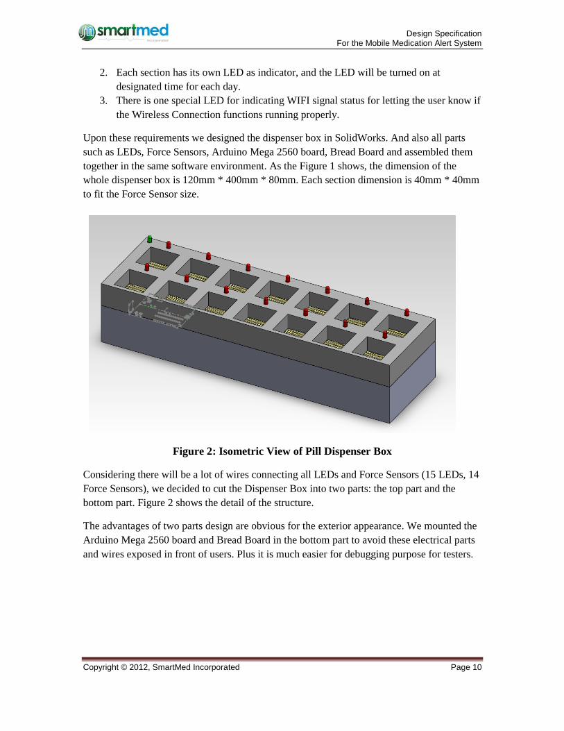
Upon these requirements we designed the dispenser box in SolidWorks. And also all parts
such as LEDs, Force Sensors, Arduino Mega 2560 board, Bread Board and assembled them
together in the same software environment. As the Figure 1 shows, the dimension of the
whole dispenser box is 120mm * 400mm * 80mm. Each section dimension is 40mm * 40mm
to fit the Force Sensor size.
Figure 2: Isometric View of Pill Dispenser Box
Considering there will be a lot of wires connecting all LEDs and Force Sensors (15 LEDs, 14
Force Sensors), we decided to cut the Dispenser Box into two parts: the top part and the
bottom part. Figure 2 shows the detail of the structure.
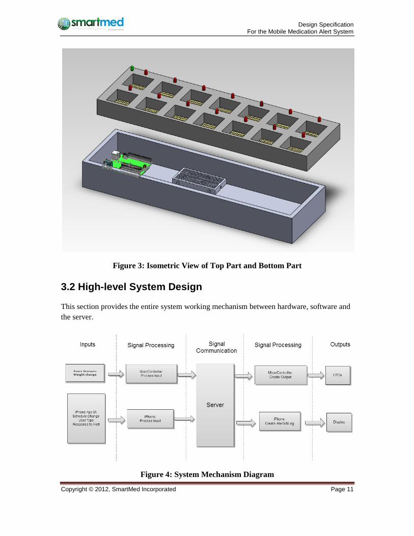
The advantages of two parts design are obvious for the exterior appearance. We mounted the
Arduino Mega 2560 board and Bread Board in the bottom part to avoid these electrical parts
and wires exposed in front of users. Plus it is much easier for debugging purpose for testers.
Design Specification For the Mobile Medication Alert System
Copyright © 2012, SmartMed Incorporated Page 11
Figure 3: Isometric View of Top Part and Bottom Part
3.2 High-level System Design
This section provides the entire system working mechanism between hardware, software and
the server.
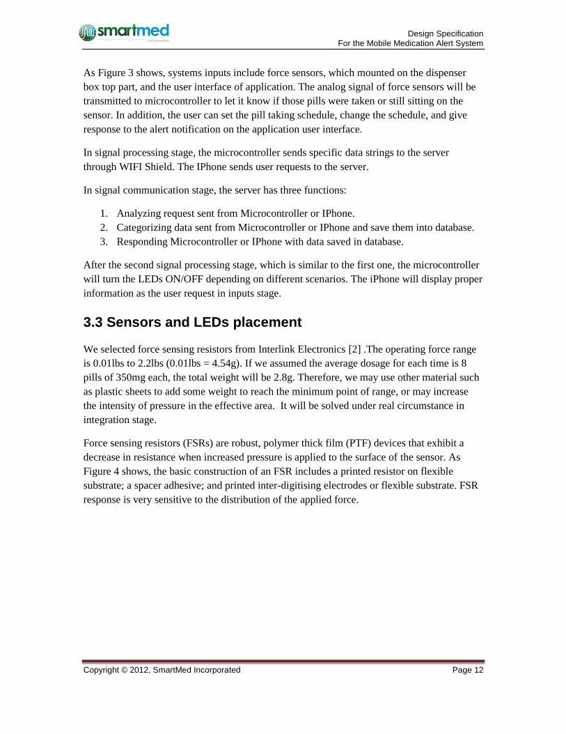
Figure 4: System Mechanism Diagram
Design Specification For the Mobile Medication Alert System
Copyright © 2012, SmartMed Incorporated Page 12
As Figure 3 shows, systems inputs include force sensors, which mounted on the dispenser
box top part, and the user interface of application. The analog signal of force sensors will be
transmitted to microcontroller to let it know if those pills were taken or still sitting on the
sensor. In addition, the user can set the pill taking schedule, change the schedule, and give
response to the alert notification on the application user interface.
In signal processing stage, the microcontroller sends specific data strings to the server
through WIFI Shield. The IPhone sends user requests to the server.
In signal communication stage, the server has three functions:
1. Analyzing request sent from Microcontroller or IPhone.
2. Categorizing data sent from Microcontroller or IPhone and save them into database.
3. Responding Microcontroller or IPhone with data saved in database.
After the second signal processing stage, which is similar to the first one, the microcontroller
will turn the LEDs ON/OFF depending on different scenarios. The iPhone will display proper
information as the user request in inputs stage.
3.3 Sensors and LEDs placement
We selected force sensing resistors from Interlink Electronics [2] .The operating force range
is 0.01lbs to 2.2lbs (0.01lbs = 4.54g). If we assumed the average dosage for each time is 8
pills of 350mg each, the total weight will be 2.8g. Therefore, we may use other material such
as plastic sheets to add some weight to reach the minimum point of range, or may increase
the intensity of pressure in the effective area. It will be solved under real circumstance in
integration stage.
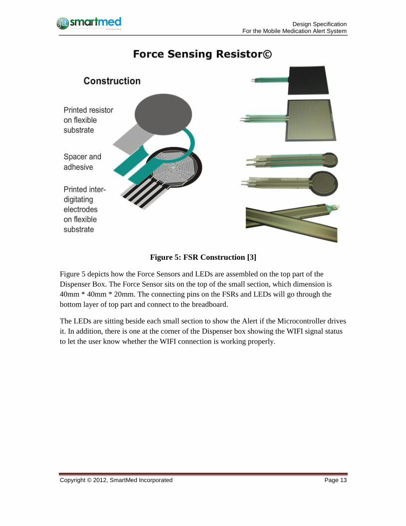
Force sensing resistors (FSRs) are robust, polymer thick film (PTF) devices that exhibit a
decrease in resistance when increased pressure is applied to the surface of the sensor. As
Figure 4 shows, the basic construction of an FSR includes a printed resistor on flexible
substrate; a spacer adhesive; and printed inter-digitising electrodes or flexible substrate. FSR
response is very sensitive to the distribution of the applied force.
Design Specification For the Mobile Medication Alert System
Copyright © 2012, SmartMed Incorporated Page 13
Figure 5: FSR Construction [3]
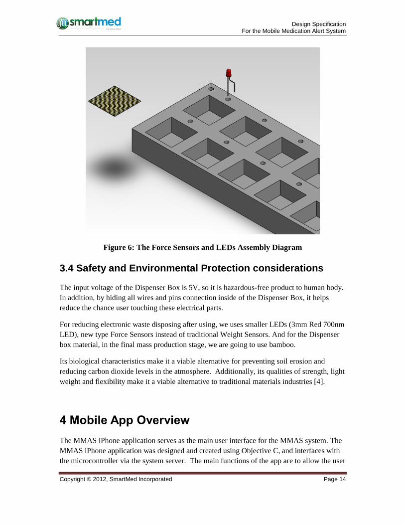
Figure 5 depicts how the Force Sensors and LEDs are assembled on the top part of the
Dispenser Box. The Force Sensor sits on the top of the small section, which dimension is
40mm * 40mm * 20mm. The connecting pins on the FSRs and LEDs will go through the
bottom layer of top part and connect to the breadboard.
The LEDs are sitting beside each small section to show the Alert if the Microcontroller drives
it. In addition, there is one at the corner of the Dispenser box showing the WIFI signal status
to let the user know whether the WIFI connection is working properly.
Design Specification For the Mobile Medication Alert System
Copyright © 2012, SmartMed Incorporated Page 14
Figure 6: The Force Sensors and LEDs Assembly Diagram
3.4 Safety and Environmental Protection considerations
The input voltage of the Dispenser Box is 5V, so it is hazardous-free product to human body.
In addition, by hiding all wires and pins connection inside of the Dispenser Box, it helps
reduce the chance user touching these electrical parts.
For reducing electronic waste disposing after using, we uses smaller LEDs (3mm Red 700nm
LED), new type Force Sensors instead of traditional Weight Sensors. And for the Dispenser
box material, in the final mass production stage, we are going to use bamboo.
Its biological characteristics make it a viable alternative for preventing soil erosion and
reducing carbon dioxide levels in the atmosphere. Additionally, its qualities of strength, light
weight and flexibility make it a viable alternative to traditional materials industries [4].
4 Mobile App Overview
The MMAS iPhone application serves as the main user interface for the MMAS system. The
MMAS iPhone application was designed and created using Objective C, and interfaces with
the microcontroller via the system server. The main functions of the app are to allow the user
Design Specification For the Mobile Medication Alert System
Copyright © 2012, SmartMed Incorporated Page 15
and secondary caregiver/loved one to view the status of the pill compartments in their pill
dispenser, either full, empty or missed; to view and change their schedule of pills to be taken
(primary only), and to notify the user of missed or improperly taken pills.
4.1 Mobile App Interface Design
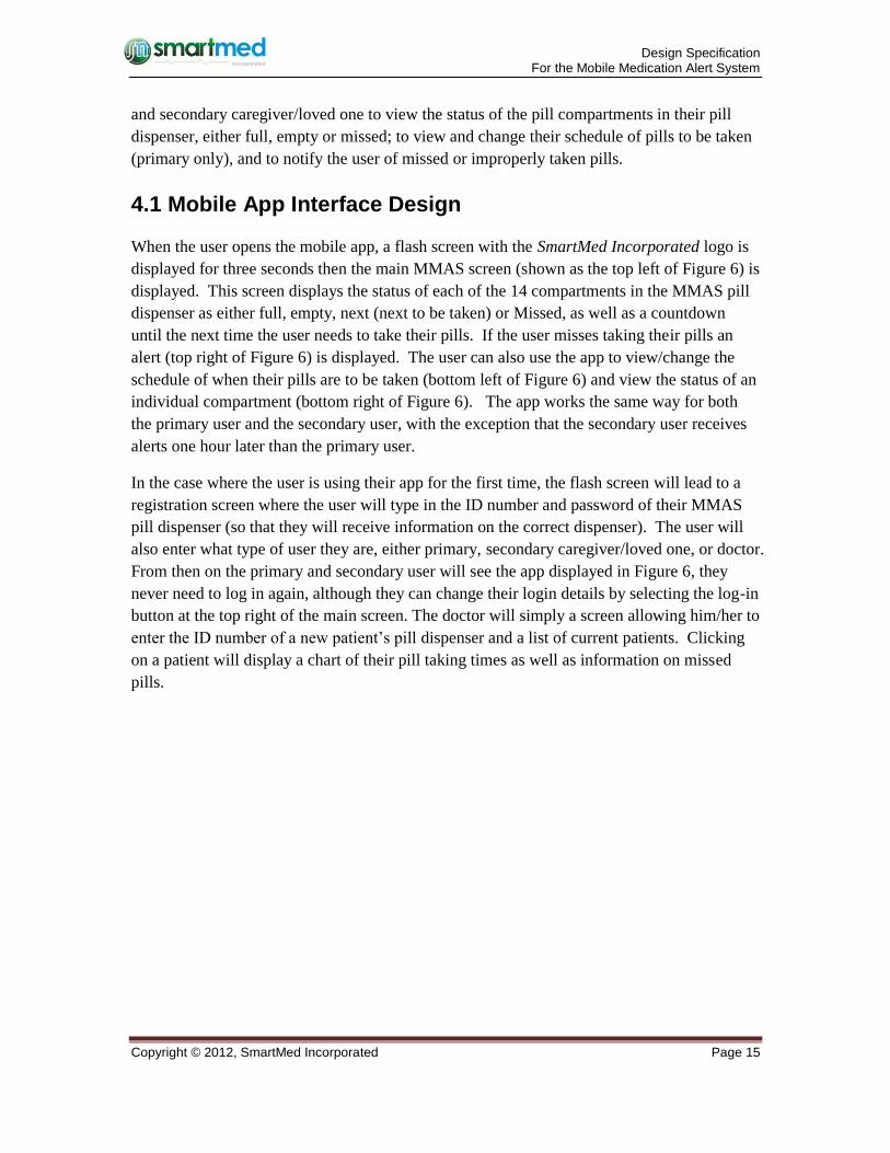
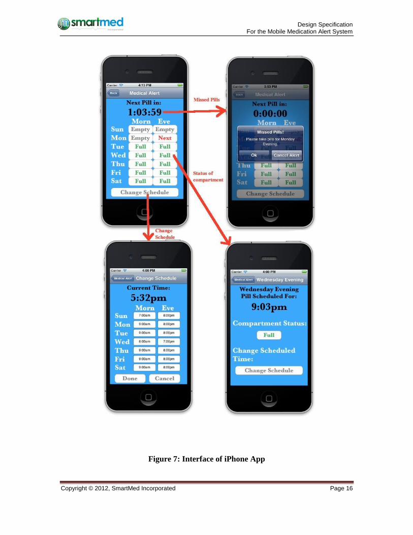
When the user opens the mobile app, a flash screen with the SmartMed Incorporated logo is
displayed for three seconds then the main MMAS screen (shown as the top left of Figure 6) is
displayed. This screen displays the status of each of the 14 compartments in the MMAS pill
dispenser as either full, empty, next (next to be taken) or Missed, as well as a countdown
until the next time the user needs to take their pills. If the user misses taking their pills an
alert (top right of Figure 6) is displayed. The user can also use the app to view/change the
schedule of when their pills are to be taken (bottom left of Figure 6) and view the status of an
individual compartment (bottom right of Figure 6). The app works the same way for both
the primary user and the secondary user, with the exception that the secondary user receives
alerts one hour later than the primary user.
In the case where the user is using their app for the first time, the flash screen will lead to a
registration screen where the user will type in the ID number and password of their MMAS
pill dispenser (so that they will receive information on the correct dispenser). The user will
also enter what type of user they are, either primary, secondary caregiver/loved one, or doctor.
From then on the primary and secondary user will see the app displayed in Figure 6, they
never need to log in again, although they can change their login details by selecting the log-in
button at the top right of the main screen. The doctor will simply a screen allowing him/her to
enter the ID number of a new patient’s pill dispenser and a list of current patients. Clicking
on a patient will display a chart of their pill taking times as well as information on missed
pills.
Design Specification For the Mobile Medication Alert System
Copyright © 2012, SmartMed Incorporated Page 16
Figure 7: Interface of iPhone App
Design Specification For the Mobile Medication Alert System
Copyright © 2012, SmartMed Incorporated Page 17
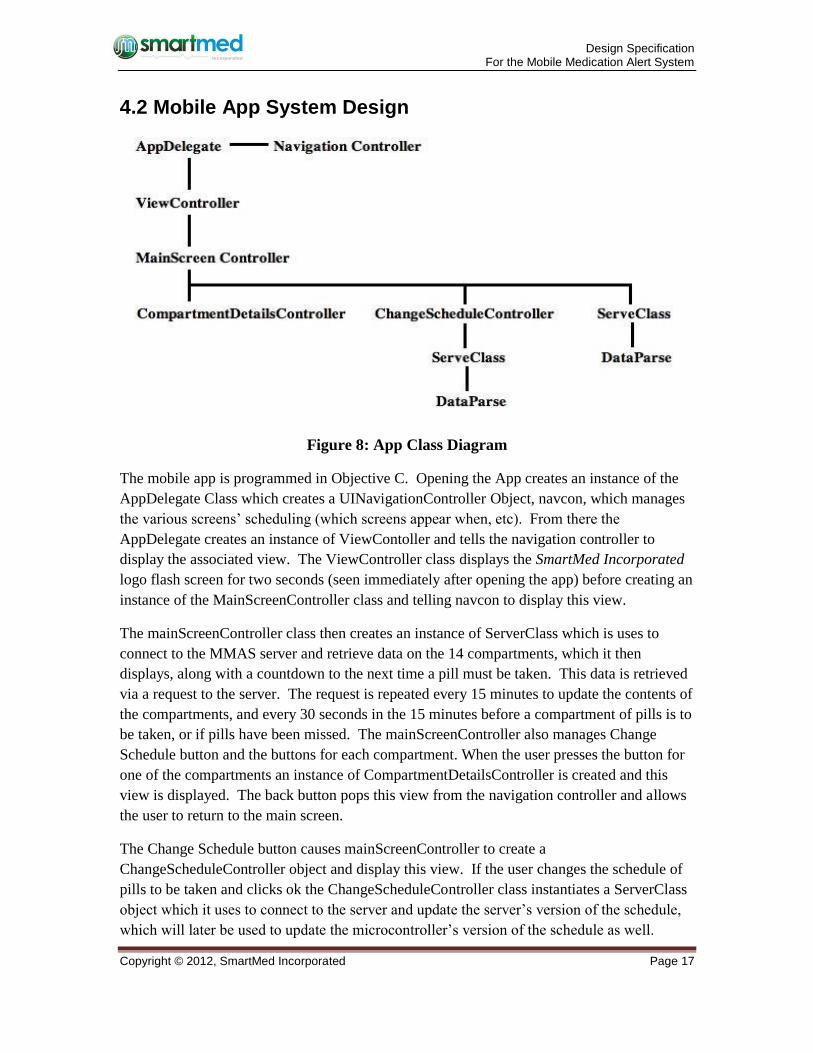
4.2 Mobile App System Design
Figure 8: App Class Diagram
The mobile app is programmed in Objective C. Opening the App creates an instance of the
AppDelegate Class which creates a UINavigationController Object, navcon, which manages
the various screens’ scheduling (which screens appear when, etc). From there the
AppDelegate creates an instance of ViewContoller and tells the navigation controller to
display the associated view. The ViewController class displays the SmartMed Incorporated
logo flash screen for two seconds (seen immediately after opening the app) before creating an
instance of the MainScreenController class and telling navcon to display this view.
The mainScreenController class then creates an instance of ServerClass which is uses to
connect to the MMAS server and retrieve data on the 14 compartments, which it then
displays, along with a countdown to the next time a pill must be taken. This data is retrieved
via a request to the server. The request is repeated every 15 minutes to update the contents of
the compartments, and every 30 seconds in the 15 minutes before a compartment of pills is to
be taken, or if pills have been missed. The mainScreenController also manages Change
Schedule button and the buttons for each compartment. When the user presses the button for
one of the compartments an instance of CompartmentDetailsController is created and this
view is displayed. The back button pops this view from the navigation controller and allows
the user to return to the main screen.
The Change Schedule button causes mainScreenController to create a
ChangeScheduleController object and display this view. If the user changes the schedule of
pills to be taken and clicks ok the ChangeScheduleController class instantiates a ServerClass
object which it uses to connect to the server and update the server’s version of the schedule,
which will later be used to update the microcontroller’s version of the schedule as well.
Design Specification For the Mobile Medication Alert System
Copyright © 2012, SmartMed Incorporated Page 18
The ServerClass object creates an instance DataParse class which it uses to parse output data
into the correct format to be sent to the server through a post request, and to parse input from
the server into data which is useable by the app.
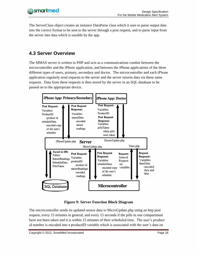
4.3 Server Overview
The MMAS server is written in PHP and acts as a communications conduit between the
microcontroller and the iPhone application, and between the iPhone applications of the three
different types of users, primary, secondary and doctor. The microcontroller and each iPhone
application regularly send requests to the server and the server returns data via these same
requests. Data from these requests is then stored by the server in an SQL database to be
passed on to the appropriate device.
Figure 9: Server Function Block Diagram
The microcontroller sends its updated sensor data to MicroUpdate.php using an http post
request, every 15 minutes in general, and every 15 seconds if the pills in one compartment
have not been taken and it is within 15 minutes of their scheduled time. The user’s product
id number is encoded into a productID variable which is associated with the user’s data on
Design Specification For the Mobile Medication Alert System
Copyright © 2012, SmartMed Incorporated Page 19
the server to insure each user receives data from their own MMAS pill dispenser. The
current sensor readings are encoded into a sensorReadings variable in a specific way, which
will be explained in section 5.8.2.This variable is then put into the post request to
MicroUpdate.php where the variable is saved, unchanged, in the server’s SQL database along
with the user’s product ID number into a table called sensorReadings, overwriting the
previous saved data for that device. The sensorReadings variable is also parsed and
compared with the perviously stored copy of sensorReadings to establish whether a pill has
been taken. In the event that a pill has been taken the date and time is saved into a table in
the SQL database called pillsTaken, along with the user’s product ID number.
The microcontroller’s request to MicroUpdate.php will not only include data on the sensors,
it will also return data to the microcontroller which represents the current schedule. The
schedule will be stored in the server’s SQL database in the variable, scheduleData and passed
back to the microcontroller as a series of digits: 0900200009002100... where every four digits
represents the scheduled time to take one compartment of pills. So, from the above example,
the first four digits, 0900 = 9am, are associated with sunday morning. The second four digit
set: 2000 = 8pm (24 hour clock) are associated with Sunday evening. The third and fourth
sets, 0900 = 9am and 2100 = 9pm are associated with Monday morning and Monday evening
respectively and so on for each of the 14 compartments. This data is then parsed by the
microcontroller and used to update its internally stored schedule, which is necessary to insure
that the LED reminders (see microcontroller section) continue to function even if the
microcontroller loses its internet connection to the server. The scheduleData variable
mentioned above will be stored in a Table called ScheduleData along with the user’s ID
number. When a microcontroller makes a request to MicroUpdata.php this table will be
searched for an entry with the correct product ID, and that scheduleData variable will be
returned to the device.
Finally whenever the Microcontroller is reset, loses power, or is turned on for the first time it
sends a general http request to Time.php and receives the current date and time encoded in a
14 digit response: 201211032200 = 2012-11-03, 2200 = 10:00pm (24 hour clock), which it
uses to update it’s internal clock.
Both the primary and secondary user’s iPhone applications send http post requests to
iPhoneUpdate.php every 15 minutes in general, and every 15 seconds if the pills in one
compartment have not been taken and it is within 15 minutes of their scheduled time. This
request includes a productID variable with the user’s product ID, as well as the variable,
scheduleData, described in the paragraph above, which encapsulates the current schedule of
times to take pills and any changes the user may have made to this schedule. This request
also returns the sensorReadings variable (described in the first paragraph of this section) to
the requesting iPhone application where it is decoded to give the current sensor readings.
Finally when the doctor turns on their app and opens the chart for a particular user, their
application sends a http post request to DoctorUpdate.php with the product ID number of the
Design Specification For the Mobile Medication Alert System
Copyright © 2012, SmartMed Incorporated Page 20
chosen patient in the post request, stored as the variable productID. The server then searches
the pillsTaken table for all entries saved with that particular user’s product ID number, and
then returns to the doctor’s application a string, the format is explained in section 5.8.2. This
list of dates and times of patients taking their pills is parsed by the iPhone and displayed in a
graph for the doctor’s convenience.
5 Low-Level System Design
This section will focus on discussing the low-level system design, including microcontroller,
WIFI shield, sensors and LEDs. The details of the data processing and communication will
also be explained.
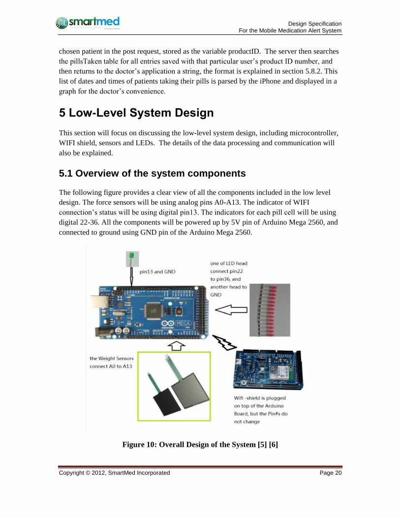
5.1 Overview of the system components
The following figure provides a clear view of all the components included in the low level
design. The force sensors will be using analog pins A0-A13. The indicator of WIFI
connection’s status will be using digital pin13. The indicators for each pill cell will be using
digital 22-36. All the components will be powered up by 5V pin of Arduino Mega 2560, and
connected to ground using GND pin of the Arduino Mega 2560.
Figure 10: Overall Design of the System [5] [6]
Design Specification For the Mobile Medication Alert System
Copyright © 2012, SmartMed Incorporated Page 21
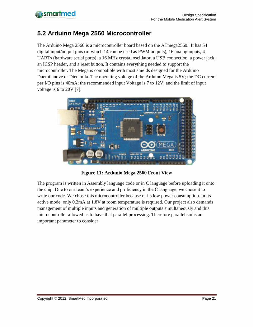
5.2 Arduino Mega 2560 Microcontroller
The Arduino Mega 2560 is a microcontroller board based on the ATmega2560. It has 54
digital input/output pins (of which 14 can be used as PWM outputs), 16 analog inputs, 4
UARTs (hardware serial ports), a 16 MHz crystal oscillator, a USB connection, a power jack,
an ICSP header, and a reset button. It contains everything needed to support the
microcontroller. The Mega is compatible with most shields designed for the Arduino
Duemilanove or Diecimila. The operating voltage of the Arduino Mega is 5V; the DC current
per I/O pins is 40mA; the recommended input Voltage is 7 to 12V, and the limit of input
voltage is 6 to 20V [7].
Figure 11: Ardunio Mega 2560 Front View
The program is written in Assembly language code or in C language before uploading it onto
the chip. Due to our team’s experience and proficiency in the C language, we chose it to
write our code. We chose this microcontroller because of its low power consumption. In its
active mode, only 0.2mA at 1.8V at room temperature is required. Our project also demands
management of multiple inputs and generation of multiple outputs simultaneously and this
microcontroller allowed us to have that parallel processing. Therefore parallelism is an
important parameter to consider.
Design Specification For the Mobile Medication Alert System
Copyright © 2012, SmartMed Incorporated Page 22
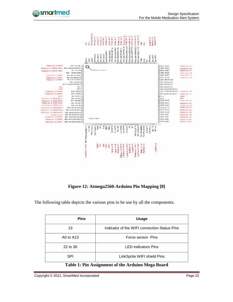
Figure 12: Atmega2560-Arduino Pin Mapping [8]
The following table depicts the various pins to be use by all the components.
Pins Usage
13 Indicator of the WIFI connection Status Pins
A0 to A13 Force sensor Pins
22 to 36 LED indicators Pins
SPI LinkSprite WIFI shield Pins
Table 1: Pin Assignment of the Arduino Mega Board

Design Specification For the Mobile Medication Alert System
Copyright © 2012, SmartMed Incorporated Page 23
5.3 Linksprite WIFI Shield
In order to connect our Arduino board with internet via wireless router, the WIFI shield is
necessary. We use the Linksprite Copperhead WIFI shield as an add-on unit for the Arduino
board.
Figure 13: LinkSprite Copperhead WIFI Shield [9]
This shield provides 802.11b connectivity with the on-board PCB antenna. The connection
speed is 1Mbps and 2Mbps and supports infrastructure and ad hoc wireless networks. It also
can access wireless networks with different security standards, e.g. WEP(64-bit and 128 bit),
WPA/WPA2(TKIP and AES) PSK[3]. The power usage is shown in the below table.
Work Mode Power Usage
Sleep 250µA
Transmit 230µA
Receive 85µA
Table 2: Power Usage in Different Work Modes of WIFI Shield
Design Specification For the Mobile Medication Alert System
Copyright © 2012, SmartMed Incorporated Page 24
The WIFI shield, as shown in the figure 12, should be plugged in on top of the Arduino board,
so that every pin should be matched each other.
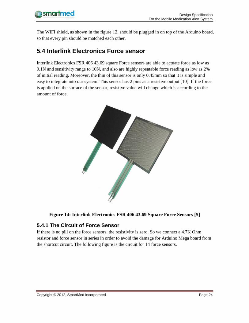
5.4 Interlink Electronics Force sensor
Interlink Electronics FSR 406 43.69 square Force sensors are able to actuate force as low as
0.1N and sensitivity range to 10N, and also are highly repeatable force reading as low as 2%
of initial reading. Moreover, the thin of this sensor is only 0.45mm so that it is simple and
easy to integrate into our system. This sensor has 2 pins as a resistive output [10]. If the force
is applied on the surface of the sensor, resistive value will change which is according to the
amount of force.
Figure 14: Interlink Electronics FSR 406 43.69 Square Force Sensors [5]
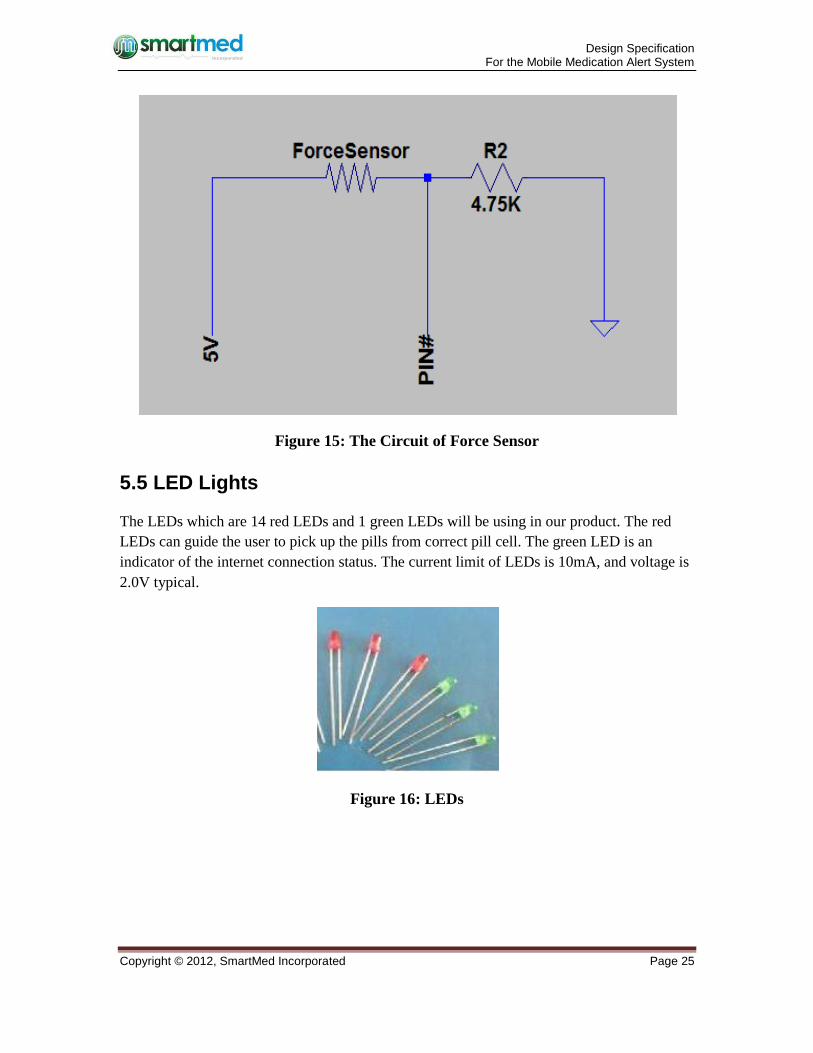
5.4.1 The Circuit of Force Sensor
If there is no pill on the force sensors, the resistivity is zero. So we connect a 4.7K Ohm
resistor and force sensor in series in order to avoid the damage for Arduino Mega board from
the shortcut circuit. The following figure is the circuit for 14 force sensors.
Design Specification For the Mobile Medication Alert System
Copyright © 2012, SmartMed Incorporated Page 25
Figure 15: The Circuit of Force Sensor
5.5 LED Lights
The LEDs which are 14 red LEDs and 1 green LEDs will be using in our product. The red
LEDs can guide the user to pick up the pills from correct pill cell. The green LED is an
indicator of the internet connection status. The current limit of LEDs is 10mA, and voltage is
2.0V typical.
Figure 16: LEDs
Design Specification For the Mobile Medication Alert System
Copyright © 2012, SmartMed Incorporated Page 26
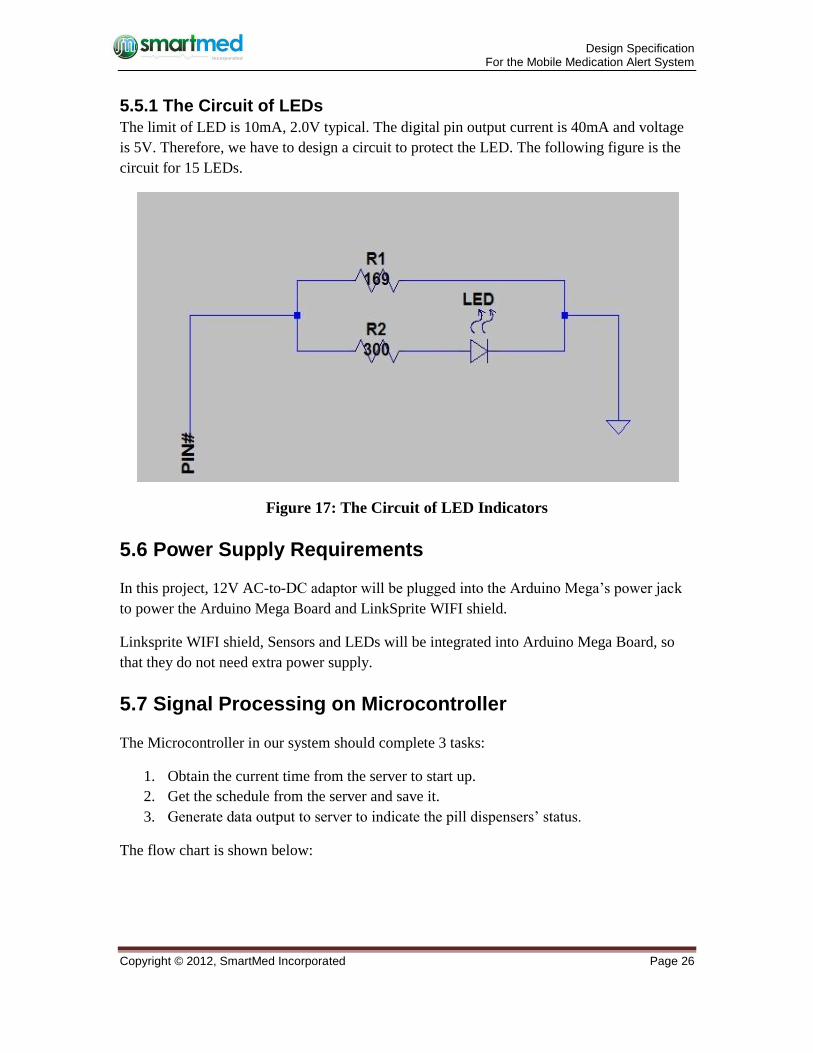
5.5.1 The Circuit of LEDs
The limit of LED is 10mA, 2.0V typical. The digital pin output current is 40mA and voltage
is 5V. Therefore, we have to design a circuit to protect the LED. The following figure is the
circuit for 15 LEDs.
Figure 17: The Circuit of LED Indicators
5.6 Power Supply Requirements
In this project, 12V AC-to-DC adaptor will be plugged into the Arduino Mega’s power jack
to power the Arduino Mega Board and LinkSprite WIFI shield.
Linksprite WIFI shield, Sensors and LEDs will be integrated into Arduino Mega Board, so
that they do not need extra power supply.
5.7 Signal Processing on Microcontroller
The Microcontroller in our system should complete 3 tasks:
1. Obtain the current time from the server to start up.
2. Get the schedule from the server and save it.
3. Generate data output to server to indicate the pill dispensers’ status.
The flow chart is shown below:
Design Specification For the Mobile Medication Alert System
Copyright © 2012, SmartMed Incorporated Page 27
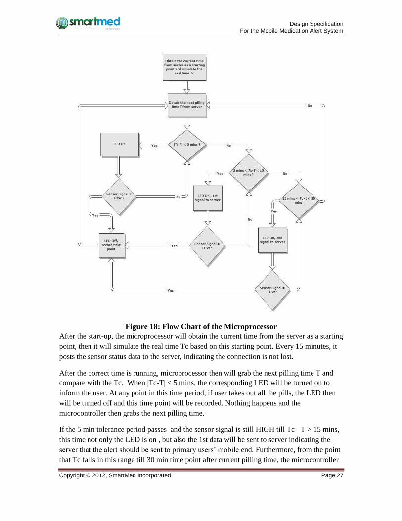
Figure 18: Flow Chart of the Microprocessor
After the start-up, the microprocessor will obtain the current time from the server as a starting
point, then it will simulate the real time Tc based on this starting point. Every 15 minutes, it
posts the sensor status data to the server, indicating the connection is not lost.
After the correct time is running, microprocessor then will grab the next pilling time T and
compare with the Tc. When |Tc-T| < 5 mins, the corresponding LED will be turned on to
inform the user. At any point in this time period, if user takes out all the pills, the LED then
will be turned off and this time point will be recorded. Nothing happens and the
microcontroller then grabs the next pilling time.
If the 5 min tolerance period passes and the sensor signal is still HIGH till Tc –T > 15 mins,
this time not only the LED is on , but also the 1st data will be sent to server indicating the
server that the alert should be sent to primary users’ mobile end. Furthermore, from the point
that Tc falls in this range till 30 min time point after current pilling time, the microcontroller
Design Specification For the Mobile Medication Alert System
Copyright © 2012, SmartMed Incorporated Page 28
will start updating the sensor status every 15 seconds to indicate whether the pill has been
taken, so the alert on iPhone won’t disappear until the pills have been taken or intentionally
gets cancelled by the iPhone users. LEDs will be turned off only when the pills have been
taken out . This time point will also be recorded.
However, when the 15 min timeline passes as well and the sensor signal is HIGH till Tc-
T>30 mins, the LED will continue to be on and the 2nd data will be sent to server indicating
that the alert should be sent to secondary users’ mobile end. The alert on mobile end can also
be cancelled by operating on iPhone UI or removing pills from the correct slot. LED on
board is not going to be off until the pills have been taken. As before, the time point is
recorded.
If the 30 min timeline reaches and the pills are still there, the microcontroller will save “xxxx”
for the time point and grab the next pilling time to continue.
All the time points saved from above operations will be sent to server once a week. These
data will eventually be sent to doctors’ mobile end so that doctors are able to track the data.
5.8 Data format in communication
This part will explain what kind of format to be used when transfer data between
microprocessor and server. Every time when Arduino either receive from or post to server,
the data must start with 4 digits productID, except for the current time retrieval. i.e. “0000”-
“9999”. Two scenarios are explained below.
5.8.1 Receive from Server
Microprocessor only needs to grab the current time and the pilling schedule from the server,
on the server end these two kinds of data can be in the below format:
Current Time: 14 digits.
Pilling schedule: 4 digits for each pilling time, the first 4 digits indicate Sunday Morning and
so on. Total length is 4 14+4=60.
E.g. From the 5th digit, the string is 090020000800........They indicate that the schedule is
9:00am on Sunday morning,8:00pm on Sunday evening and 8:00am on Monday morning.
5.8.2 Post to Server
Microprocessor needs to post 3 kinds of data: sensor status (update every 15 mins in
general,15 seconds starting from the15 mins range after the scheduled time.), alert and time
points when the pills had been taken.
Design Specification For the Mobile Medication Alert System
Copyright © 2012, SmartMed Incorporated Page 29
When posting alert data, microprocessor will send twice at most, according to the flow chart.
We use 2 bits to represent them. The first bit indicates the index of the data, “0” for the first
alert, “1” for the second alert. The second bit indicates the sensor status, which is always "1"
when this data needs to be sent. Since the alert cancellation only depends on whether the
sensor status has been changed or iPhone user’s intention, so microprocessor doesn't need to
update this bit stream on server. Only the LED status on board will be updated according to
the sensor's status. Therefore in this case, the length of the data is 6.
E.g. On the device with product ID “1000”,the 1st data is generated when 5mins <Tc-T< 15
mins, if the pills haven't been taken out during this period, "100001" would be sent.
The sensor status needs to be posted every 15 seconds to notify the iPhone to cancel the alert.
Since the critical point of the voltage on the sensor is 0 volts, so we use “0” to indicate the
slot is empty and “1” for non-empty. Therefore this data stream contains 18 bits( 4 digits for
the productID). E.g. “123400011111111111” indicates that on the productID “1234”, the first
3 slots are empty.
After each 7 day period, the microcontroller will send the history data of the past 7days to
server. It will use 4 digits to represent each time point. If “xxxx” exists, it indicates the pills
for that time had not been taken eventually. In this way, server can parse each 4 digit and
generate the history log for doctors’ mobile end. The length of the data stream is 14×4+4=60.
6 User Interface Unit
The user interface allows the user and secondary caregiver/loved one to view the status of the
pillbox and to set up the alert system using an iPhone App. The iPhone App consist of 4
screens to display the status of each of the 14 compartments in the MMAS pill dispenser, a
countdown until next time to taking pills, an alert for taking the wrong pills or missing taking
the pills and the time schedule of taking pills which shown as Figure 6. The user interface
will also feature some LEDs to indicate the status of pill dispenser directly. These LEDs will
be mounted just beside the corresponding compartments of pill dispenser. Shown as Figure 2
6.1 User Interface Hardware
The hardware will consist of 15 LEDs, one of them is green and the other fourteen are all red.
The green LED will be used for the status of WIFI signal for pill dispenser; the other fourteen
red LEDs will be used to indicate the status of each section for user and debugging purpose.
Shown as Figure 2
The green LED will turn on if the microcontroller detect the signal from WIFI Shield and
will turn off if there is no WIFI signal detected.
Design Specification For the Mobile Medication Alert System
Copyright © 2012, SmartMed Incorporated Page 30
When the time comes for taking pills, the corresponding red LED will turn on 5 minutes in
advance. After the pills are taken, the LED will then turn off automatically.
6.2 User Interface Software
The software of MMAS will take the inputs from the iPhone App.
6.2.1 Registration Screen
In order to keep track of a user’s pills safely, the user need to register his/her own file by
typing the ID number and password of their MMAS. The user will also need to enter what
type of user they are, either primary, secondary caregiver/loved one, or doctor. From then on
the primary and secondary user will see the app displayed in Figure 6, they never need to log
in again, although they can change their login details by selecting the login button at the top
right of the main screen.
6.2.2 Main Screen for Primary or Secondary User
The main screen displays the status of each of the 14 compartments in the MMAS pill
dispenser as either full, empty, next (next to be taken) or Missed, as well as a countdown
until the next time the user needs to take their pills.
6.2.3 Alert Message for Primary or Secondary User
If the user misses taking their pills, an alert will be displayed. Shown as Figure 6. The
primary user will receive the alert immediately. However, the secondary user will receive the
alert one hour later than the primary user.
6.2.4 Time Schedule for Primary or Secondary User
By clicking the Change Schedule button of main screen, the time schedule screen will show
up. The user can view or change the time schedule of when their pills are to be taken.
6.2.5 Interface for Doctors
The doctors will simply see a screen allowing him/her to enter the ID number of a new
patient’s pill dispenser and a list of current patients after login. Clicking on a patient will
display a chart of their pill taking times as well as information on missed pills.
6.3 User Interface Verification
The following tests will be performed in order to test the user interface:
1. Turning on and off the WIFI cause the green LED on or off.
2. Taking away the pills cause the corresponding red LED turn off.
Design Specification For the Mobile Medication Alert System
Copyright © 2012, SmartMed Incorporated Page 31
7 System Test Plan
First, each individual part of Mobile Medication Alert System will be tested separated,
including fourteen force sensors, LED lights, microcontroller, WIFI Shield, server and the
iPhone App. Next, the ideal operation of integrated overall system will be examined as well
as other normal and extreme cases.
7.1 Unit Testing
In order to guarantee every component of the Mobile Medication Alert System (MMAS) is
working properly and the corresponding information presented by the LEDs and on iPhone
App is correct, we plan to test each component of the MMAS separately, including each
version of the iPhone app, the server and the microprocessor. These tests will correspond to
the requirements outlined in our requirements document and will include:
1. Monitor the WIFI status LED while connecting/disconnecting the microcontroller to
the internet.
2. Verify the microcontroller is able to obtain the current time from the server and
simulate the clock by using it as a starting point.
3. Verify the microcontroller is able to obtain the schedule data from the server and
store them.
4. After the microcontroller is connected to internet, verify it is able to post a formatted
data request to the server’s PHP page and receive the proper response from the server.
5. Connect one sensor circuit and one LED circuit to the microcontroller properly, put
pills on the sensor and remove them one by one, monitor the LED status.
6. Monitoring the data sent to server and corresponding LED after the sensor input
changes during the 3 critical time periods i.e. -5 min - 5min, 5min-15min and 15min-
30 min.
7. Verify the iPhone is able to obtain the sensor data from the server and store it.
8. Verify the iPhone app is able to upload the current schedule to the server and that the
schedule is stored properly in the SQL database
9. Verify each of the three PHP pages on the server, MicroUpdate.php,
iPhoneUpdate.php and Time.php accept post (input data) and store it correctly, and
return correctly formatted reponse (output) data.
We will be testing for both normal test cases, where the expected input and user behaviour is
received, and extreme cases where the worst possible input/user behaviour is tested to insure
there are no failures in the system. Some extreme test cases we will be conduction include:
1. Sending improperly formatted responses to standard http requests from the
microprocessor.
Design Specification For the Mobile Medication Alert System
Copyright © 2012, SmartMed Incorporated Page 32
2. Sending improperly formatted responses to standard http requests from the iPhone
App.
3. Sending improperly formatted requests to the server.
4. Shaking the MMAS pill dispenser device to insure structural integrity.
7.2 System Testing
The next phase of our test plan is overall system testing where the MMAS will be tested as a
whole. The system will again be tested to insure that it meets the requirements outlined in
the requirements document. Both normal (expected) test cases and extreme (worst case) test
cases will be carried out. Some of the system tests to be conducted are outlined below.
7.2.1 Normal Case 1: Notification for Taking Pills on Time
User Input: The user set alert system by iPhone App and the correct pills have been taken on
time.
Conditions: The pill box and WIFI are both on power. The user’s iPhone is on.
Expected Observation: The LED light of the corresponding section of pill box should turn off,
the interface of iPhone App should show as Figure 6.
7.2.2 Normal Case 2: Notification for Forgotten to Taking Pills
User Input: The user set alert system by iPhone App and no pill has been taken on time.
Conditions: The pill box and WIFI are both on power. The user’s iPhone is on.
Expected Observation: The LED light of the corresponding section of pill box should turn on,
the user should receive an alert message from iPhone App which is shown as Figure 6.
7.2.3 Normal Case 3: Notification for Taking Wrong Pills
User Input: The user set alert system by iPhone App and the wrong pills have been taken.
Conditions: The pill box and WIFI are both on power. The user’s iPhone is on.
Expected Observation: The LED light of the corresponding section of pill box should turn off,
the user should receive an alert message from iPhone App which is shown as Figure 6.
7.2.4 Normal Case 4: Notification for No Response by User
User Input: The user set alert system by iPhone App and the no pill has been taken or the
pills have been taken incorrectly. The user’s iPhone has no response for the alert message.
Design Specification For the Mobile Medication Alert System
Copyright © 2012, SmartMed Incorporated Page 33
Conditions: The pill box and WIFI are both on power. The user’s iPhone is on.
Expected Observation: The LED light of the correct section of pill box should turn on, the
user’s designated loved one or caregiver should receive another alert message from iPhone
App which is shown as Figure 6.
7.2.5 Extreme Case 1: No Power for Pillbox and WI-FI Shield
User Input: The user set alert system by iPhone App.
Conditions: The pill box and WIFI are both power off. The user’s iPhone is on.
Expected Observation: The user should receive an alert message from iPhone App.
7.3 User System Testing
The final stage of our test plan will involve non-technical test users trying out the MMAS
system. The user’s will be asked to set up the different types of MMAS user accounts and
complete various tasks, such as changing the schedule and checking the status of pills in the
pill dispenser according to a uniform list of tasks. Feedback from these users on what is
confusing about the MMAS product and what could be done to improve will then be
integrated during our final design iteration.
8 Conclusion
We have outlines the details of the design specifications of our product, the Mobile
Medication System Alert. These design specifications will serve as guideline for designing
and testing the prototype of MMAS. The design specification provides clear targets for the
development and completion of the MMAS prototype. We believe to make a complete,
functional, user-friendly prototype module of MMAS ready by the target date of December
10th, 2012.
Design Specification For the Mobile Medication Alert System
Copyright © 2012, SmartMed Incorporated Page 34
9 Reference
[1] Top 6 Medication Problems and How to Prevent Them. [Online]
http://www.agingcare.com/Articles/medication-problems-elderly-people-have-146111.htm
[Accessed: November 1, 2012]
[2] Interlink Electronics, Sensor Technologies. [Online]
http://www.digikey.com/Suppliers/us/interlink-
electronics.page?lang=en&WT.z_ptm_structured=Supplier%20Logo [Accessed: November 3,
2012]
[3] Force Sensing Resistors PTM by Digi-Key and Interlink. [Online]
http://dkc1.digikey.com/us/en/tod/Interlink/Force-Sensing-Resistor/Force-Sensing-
Resistor.html [Accessed: November 3, 2012]
[4] Bamboo & Environment. [Online]
http://www.mastergardenproducts.com/sustainablelandscape/bambooenvironment.htm
[Accessed: November 3, 2012]
[5] Arduino Mega. [Online] http://www.arduino.cc/en/Main/arduinoBoardMega [Accessed:
November 1, 2012]
[6] LinkSprite CuHead WiFi Shield for Arduino Mega. [Online]
http://www.robotshop.com/linksprite-cuhead-wifi-shield-arduino-mega.html [Accessed:
November 1, 2012]
[7] Copperhead WiFi Shield for Arduino [online]
http://www.linksprite.com/product/showproduct.php?lang=en&id=73 [Accessed Nov 3
2012].
[8] ATmega2560-Arduino Pin Mapping. [Online]
http://arduino.cc/en/Hacking/PinMapping2560 [Accessed: November 1, 2012]
[9] LinkSprite Copperhead Wifi Shield V2.0 for Arduino Mega. [online] http://www.play-
zone.ch/en/linksprite-copperhead-wifi-shield-v2-0-for-arduino-mega.html [Accessed Nov
5 2012]
[10] Force Sensor. [Online] http://www.digikey.com/product-detail/en/30-73258/1027-
1002-ND/2476470 [Accessed Nov 2 2012]