Embed Size (px)
Citation preview
CatalogD 21.7
Part 12013
Answers for industry.
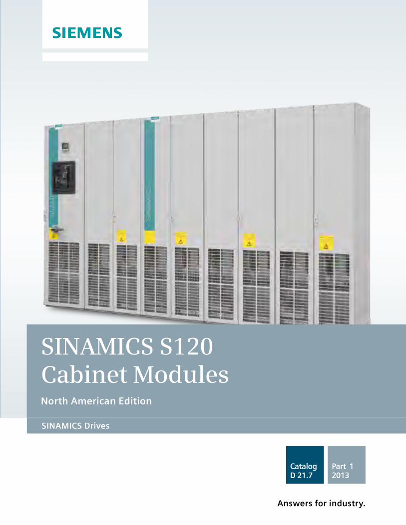
SINAMICS S120 Cabinet Modules North American Edition
SINAMICS Drives SINAMICS Drives
Related Catalogs The Engineering Manual
SINAMICS S120 Chassis Format Units and Cabinet Modules
SINAMICS S150 Converter Cabinet UnitsCatalog D 21.3 • 2011
SINAMICS Drives
Answers for industry.
SINAMICS S120 Chassis Format Units and Cabinet Modules
SINAMICS S150 Converter Cabinet UnitsCatalog D 21.3 • 2011
SINAMICS Drives
Answers for industry.
SIMOTION, SINAMICS S120 and Motors for Production MachinesCatalog PM 21 • 2011
Motion Control
Answers for industry.
Siemens Industry, Inc.3333 Old Milton ParkwayAlpharetta, GA 30005
Subject to change without prior notice.Order No: DRCA-D1171-0313All rights reserved.Printed in USA.©2013 Siemens Industry, Inc. Catalog
D 11.7Part 12013
Answers for industry.
The information provided in this brochure contains merely general descriptions or characteristics of performance which in case of actual use do not always apply as described or which may change as a result of further development of the products. An obligation to provide the respectivecharacteristics shall only exist if expressly agreed in the terms of contract.
Siemens is a registered trademark of Siemens AG. Product names mentioned may be trademarks or registered trademarks of their respective companies. Specificationsare subject to change without notice.www.usa.siemens.com/drives
SINAMICS Drives
SINAMICS G150 NEMA Enclosed Drives
SINAMICS G130 Drive Converter Chassis Units SINAMICS G150 Drive Converter Cabinet Units
Catalog D 11 • 2011
SINAMICS Drives
Answers for industry.
SINAMICS and Motors for Single-Axis DrivesCatalog D 31 • 2012
Motion Control Drives
Answers for industry.
SIMOTICS NEMA Motors
www.usa.siemens.com/nema-motors
Low Voltage AC Motors Selection and Pricing Guide
Catalog D81.2 - 2012, USA Edition
SIMOTICS Low-Voltage Motors Type series 1LE, 1PC, 1LA, 1LG, 1LL, 1LP, 1MA, 1MJ, 1PP, 1PQ Frame sizes 63 to 450 Power range 0.09 to 1250 kW
Catalog D 81.1 • January 2012
Motors
Answers for industry.
Inte
rnational Efficiency
IE changeover
Standard Ef �ciency
High Ef �ciency
Premium Ef �ciency
SINAMICS S120 D21.3 • 2011Chassis Units and Cabinet Modules (IEC)SINAMICS S150Drive Converter Cabinet Units (IEC)E86060-K5521-A131-A3-7600DRCA-21300-0412
SIMOTION, SINAMICS S120 andMotors for Production Machines Catalog PM 21 • 2011
E86060-K4921-A101-A2-7600DRCA-K4921-0111
SINAMICS G150 NEMA D11.7.1 • 2013 Enclosed Drives
DRCA-D1171-0313
SINAMICS G130 D11 • 2011Drive Converter Chassis UnitsSINAMICS G150Drive Converter Cabinet Units (IEC)E86050-K5511-A101-A5-7600DRCA-D1100-0412
SINAMICS and Motors for Single-Axis Drives D31 • 2012
E86050-K5531-A101-A1-7600DRCA-D3112-0412
Low Voltage AC Motors D81.2 • 2012Selection and Pricing Guide, USA Edition
NMPC-00600-0212
SIMOTICS Low-Voltage Motors (IEC) D81.1 • 2012Frame sizes 63 to 450Power range 0.09 to 1250 kW
E86060-K5581-A111-A4-7600
SINAMICS GM150, SINAMICS SM150Medium Voltage Converters D12 • 2012 E86060-K5512-A101-A3-7600
SINAMICS Low Voltage Engineering Manual
Engineering Manual for SINAMICS G130 Drive Chassis, SINAMICS G150 Enclosed Drives, SINAMICS S120 Drive Chassis, SINAMICS S120 Cabinet Modules, SINAMICS S150 Enclosed Drives
The engineering manual is divided into the following chapters: - Fundamental Principles and System Description - EMC Installation Guideline - General Engineering Information for SINAMICS - SINAMICS G130 Converter Chassis Units - SINAMICS G150 Converter Cabinet Units - SINAMICS S120 Chassis Format Units and Cabinet Modules - SINAMICS S150 Converter Cabinet Units - Drive Dimensioning - Motors
This manual offers users comprehensive support for the configuring of drives and associated system components.
The first three chapters are devoted primarily to the fundamental physical principles of variable speed electric drives and include EMC Installation Guidelines as well as general system descriptions and planning information which relate to all products in the SINAMICS range. The other chapters then discuss in detail questions relating to the dimensioning of specific drive models as well as the selection of suitable motors.
Note: The engineering manual is not available as a printed hard copy, but only as an electronic file in PDF format.
SINAMICS Drives
SINAMICS S120Cabinet Modules
North American Edition
Catalog D21.7 (part 1) • 2013
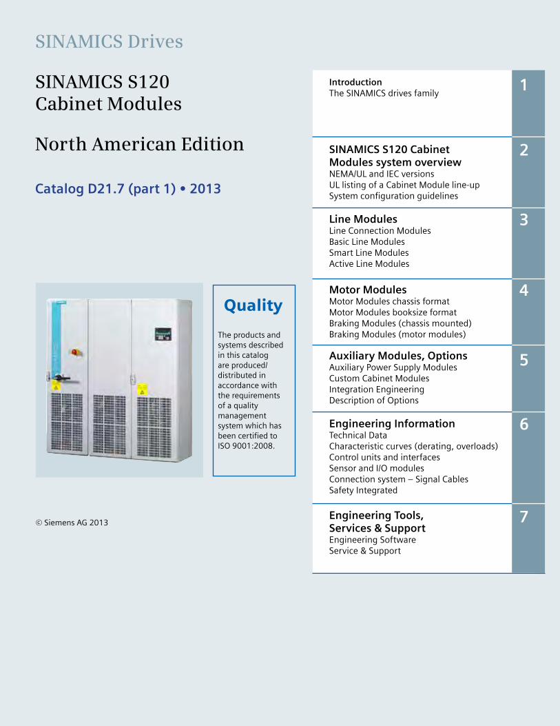
Introduction The SINAMICS drives family
SINAMICS S120 CabinetModules system overviewNEMA/UL and IEC versionsUL listing of a Cabinet Module line-upSystem configuration guidelines
Line ModulesLine Connection ModulesBasic Line ModulesSmart Line ModulesActive Line Modules
Motor ModulesMotor Modules chassis formatMotor Modules booksize format Braking Modules (chassis mounted)Braking Modules (motor modules)
Auxiliary Modules, OptionsAuxiliary Power Supply ModulesCustom Cabinet ModulesIntegration EngineeringDescription of Options
Engineering InformationTechnical DataCharacteristic curves (derating, overloads)Control units and interfacesSensor and I/O modulesConnection system – Signal CablesSafety Integrated
Engineering Tools, Services & SupportEngineering SoftwareService & Support
1
2
3
4
5
6
7© Siemens AG 2013
The products andsystems described in this catalog are produced/distributed inaccordance with the requirementsof a qualitymanagementsystem which hasbeen certified to ISO 9001:2008.
Quality
0/2 Siemens D21.7 – 2013
SINAMICS Drives
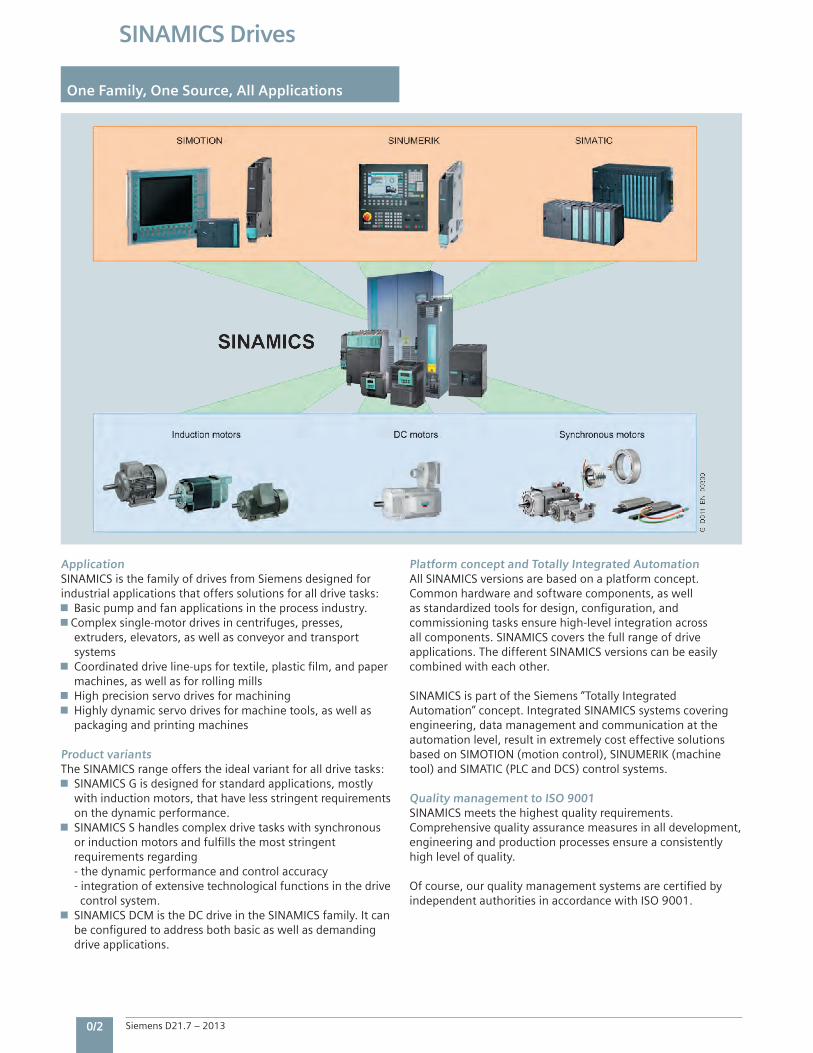
One Family, One Source, All Applications
ApplicationSINAMICS is the family of drives from Siemens designed for industrial applications that offers solutions for all drive tasks:
Basic pump and fan applications in the process industry. Complex single-motor drives in centrifuges, presses,
extruders, elevators, as well as conveyor and transport systemsCoordinated drive line-ups for textile, plastic film, and paper
machines, as well as for rolling millsHigh precision servo drives for machiningHighly dynamic servo drives for machine tools, as well as
packaging and printing machines Product variantsThe SINAMICS range offers the ideal variant for all drive tasks:SINAMICS G is designed for standard applications, mostly
with induction motors, that have less stringent requirements on the dynamic performance.SINAMICS S handles complex drive tasks with synchronous
or induction motors and fulfills the most stringent requirements regarding - the dynamic performance and control accuracy - integration of extensive technological functions in the drive control system.SINAMICS DCM is the DC drive in the SINAMICS family. It can
be configured to address both basic as well as demanding drive applications.
Platform concept and Totally Integrated AutomationAll SINAMICS versions are based on a platform concept. Common hardware and software components, as well as standardized tools for design, configuration, and commissioning tasks ensure high-level integration across all components. SINAMICS covers the full range of drive applications. The different SINAMICS versions can be easily combined with each other. SINAMICS is part of the Siemens “Totally Integrated Automation” concept. Integrated SINAMICS systems covering engineering, data management and communication at the automation level, result in extremely cost effective solutions based on SIMOTION (motion control), SINUMERIK (machine tool) and SIMATIC (PLC and DCS) control systems. Quality management to ISO 9001SINAMICS meets the highest quality requirements.Comprehensive quality assurance measures in all development, engineering and production processes ensure a consistently high level of quality. Of course, our quality management systems are certified by independent authorities in accordance with ISO 9001.
5
SINAMICS S120 Cabinet ModulesIntroduction
1/2 The members of the SINAMICS drives family SINAMICSlowvoltagedrives SINAMICSDCdrives SINAMICSmediumvoltagedrives TheSINAMICSS120range
1
SiemensD21.7–2013
1
1/2 Siemens D21.7 – 2013
SINAMICS S120 Cabinet Modules
Introduction
The SINAMICS drives family
SINAMICS low voltage drives
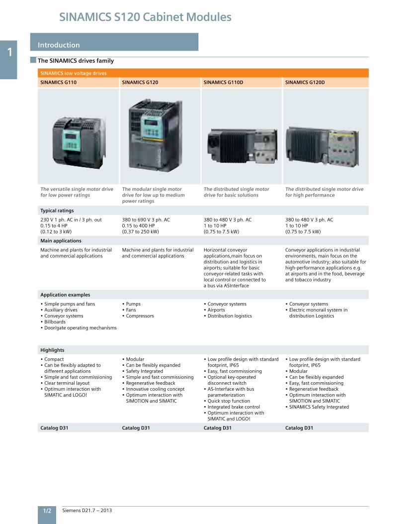
SINAMICS G110 SINAMICS G120 SINAMICS G110D SINAMICS G120D
The versatile single motor drive for low power ratings
The modular single motor drive for low up to medium power ratings
The distributed single motor drive for basic solutions
The distributed single motor drive for high performance
Typical ratings
230V1ph.ACin/3ph.out0.15to4HP(0.12to3kW)
380to690V3ph.AC0.15to400HP(0.37to250kW)
380to480V3ph.AC1to10HP(0.75to7.5kW)
380to480V3ph.AC1to10HP(0.75to7.5kW)
Main applications
Machineandplantsforindustrialandcommercialapplications
Machineandplantsforindustrialandcommercialapplications
Horizontalconveyorapplications,mainfocusondistributionandlogisticsinairports;suitableforbasicconveyor-relatedtaskswithlocalcontrolorconnectedtoabusviaASInterface
Conveyorapplicationsinindustrialenvironments,mainfocusontheautomotiveindustry;alsosuitableforhigh-performanceapplicationse.g.atairportsandinthefood,beverageandtobaccoindustry
Application examples
•Simplepumpsandfans•Auxiliarydrives•Conveyorsystems•Billboards•Door/gateoperatingmechanisms
•Pumps•Fans•Compressors
•Conveyorsystems•Airports•Distributionlogistics
•Conveyorsystems•Electricmonorailsystemin distributionLogistics
Highlights
•Compact•Canbeflexiblyadaptedto differentapplications•Simpleandfastcommissioning•Clearterminallayout•Optimuminteractionwith SIMATICandLOGO!
•Modular•Canbeflexiblyexpanded•SafetyIntegrated•Simpleandfastcommissioning•Regenerativefeedback•Innovativecoolingconcept•Optimuminteractionwith SIMOTIONandSIMATIC
•Lowprofiledesignwithstandard footprint,IP65•Easy,fastcommissioning•Optionalkey-operated disconnectswitch•AS-Interfacewithbus parameterization•Quickstopfunction•Integratedbrakecontrol•Optimuminteractionwith SIMATICandLOGO!
•Lowprofiledesignwithstandard footprint,IP65•Modular•Canbeflexiblyexpanded•Easy,fastcommissioning•Regenerativefeedback•Optimuminteractionwith SIMOTIONandSIMATIC•SINAMICSSafetyIntegrated
Catalog D31 Catalog D31 Catalog D31 Catalog D31
1
Siemens D21.7 – 2013 1/3
SINAMICS S120 Cabinet Modules
Introduction
The SINAMICS drives family
SINAMICS low voltage drives
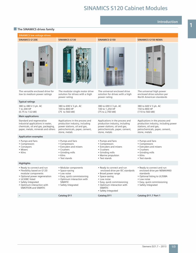
SINAMICS G120E SINAMICS G130 SINAMICS G150 SINAMICS G150 NEMA
The versatile enclosed drive for low to medium power ratings
The modular single motor drive solution for drives with a high power rating
The universal enclosed drive solution for drives with a high power rating
The universal high power enclosed drive solution per North American standards
Typical ratings
380 to 480 V 3 ph. AC1 to 200 HP(0.75 to 132 kW)
380 to 690 V 3 ph. AC100 to 800 HP(75 to 560 kW)
380 to 690 V 3 ph. AC100 to 1,250 HP(75 to 2,700 kW)
380 to 600 V 3 ph. AC150 to 800 HP(110 to 560 kW)
Main applications
Standard and regenerative industrial applications in water, chemicals, oil and gas, packaging, paper, metals, minerals and others
Applications in the process and production industry, including power stations, oil and gas, petrochemicals, paper, cement, stone, metals
Applications in the process and production industry, including power stations, oil and gas, petrochemicals, paper, cement, stone, metals
Applications in the process and production industry, including power stations, oil and gas, petrochemicals, paper, cement, stone, metals
Application examples
• Pumps and fans• Compressors• Conveyors• Mixers• Kilns
• Pumps and fans• Compressors• Extruders and mixers• Crushers• Grinding mills• Kilns• Test stands
• Pumps and fans• Compressors• Extruders and mixers• Crushers• Grinding mills• Marine propulsion• Test stands
• Pumps and fans• Compressors• Extruders and mixers• Crushers• Grinding mills• Kilns• Test stands
Highlights
• Ready to connect and run• Flexibility based on G120 modular components• Optional power regeneration• UL508C listed• Safety Integrated• Optimum interaction with SIMOTION and SIMATIC
• Modular components • Space-saving• Low noise• Easy, quick commissioning• Optimum interaction with SIMATIC• Safety Integrated
• Ready to connect and run enclosed drive per IEC standards• Broad power range• Space-saving• Low noise• Easy, quick commissioning• Optimum interaction with SIMATIC• Safety Integrated
• Ready to connect and run enclosed drive per NEMA/ANSI standards• Optional listing to UL508A• Low noise• Easy, quick commissioning• Safety Integrated
– Catalog D11 Catalog D11 Catalog D11.7 Part 1
1
1/4 Siemens D21.7 – 2013
SINAMICS S120 Cabinet Modules
The SINAMICS drives family
SINAMICS low voltage drives SINAMICS DC drives
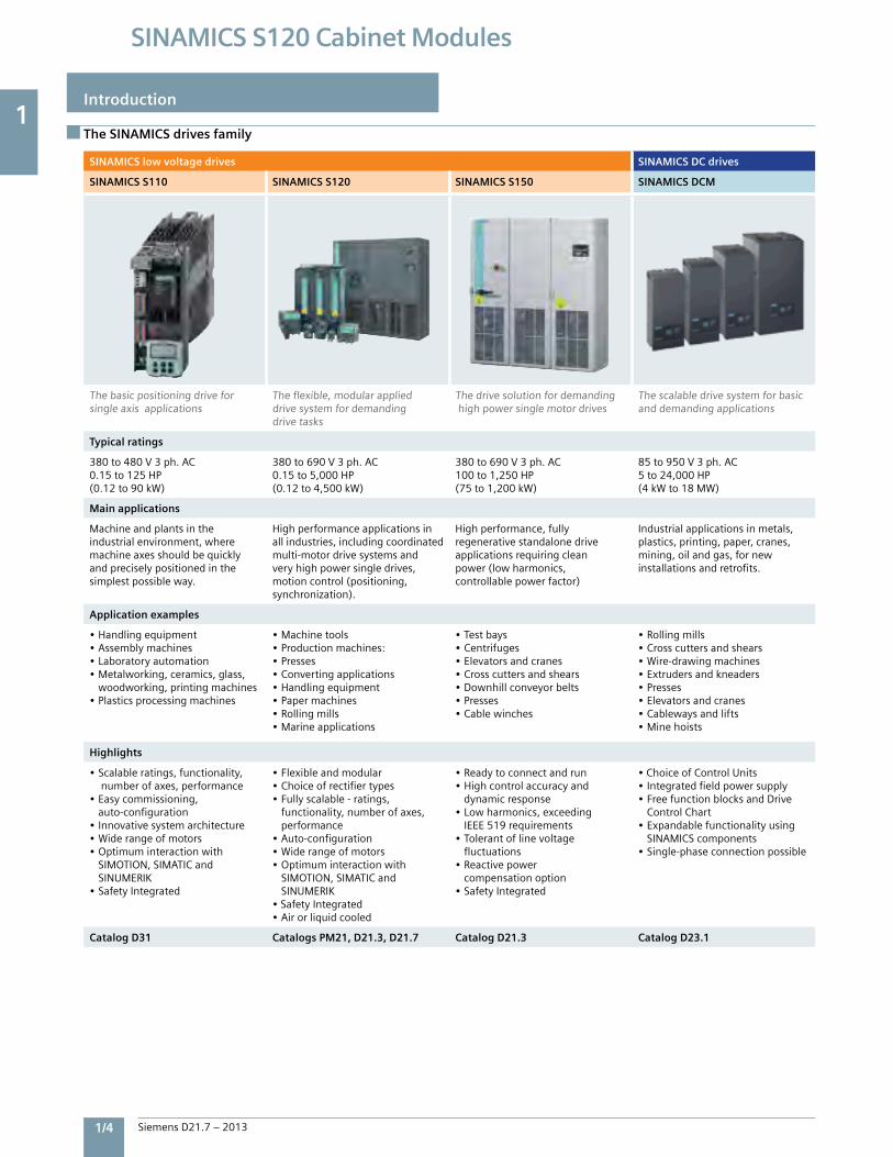
SINAMICS S110 SINAMICS S120 SINAMICS S150 SINAMICS DCM
Thebasicpositioningdriveforsingleaxisapplications
Theflexible,modularapplieddrivesystemfordemandingdrivetasks
Thedrivesolutionfordemandinghighpowersinglemotordrives
Thescalabledrivesystemforbasicanddemandingapplications
Typical ratings
380to480V3ph.AC0.15to125HP(0.12to90kW)
380to690V3ph.AC0.15to5,000HP(0.12to4,500kW)
380to690V3ph.AC100to1,250HP(75to1,200kW)
85to950V3ph.AC5to24,000HP(4kWto18MW)
Main applications
Machineandplantsintheindustrialenvironment,wheremachineaxesshouldbequicklyandpreciselypositionedinthesimplestpossibleway.
Highperformanceapplicationsinallindustries,includingcoordinatedmulti-motordrivesystemsandveryhighpowersingledrives,motioncontrol(positioning,synchronization).
Highperformance,fullyregenerativestandalonedriveapplicationsrequiringcleanpower(lowharmonics,controllablepowerfactor)
Industrialapplicationsinmetals,plastics,printing,paper,cranes,mining,oilandgas,fornewinstallationsandretrofits.
Application examples
•Handlingequipment•Assemblymachines•Laboratoryautomation•Metalworking,ceramics,glass, woodworking,printingmachines•Plasticsprocessingmachines
•Machinetools•Productionmachines:•Presses•Convertingapplications•Handlingequipment•Papermachines•Rollingmills•Marineapplications
•Testbays•Centrifuges•Elevatorsandcranes•Crosscuttersandshears•Downhillconveyorbelts•Presses•Cablewinches
•Rollingmills•Crosscuttersandshears•Wire-drawingmachines•Extrudersandkneaders•Presses•Elevatorsandcranes•Cablewaysandlifts•Minehoists
Highlights
•Scalableratings,functionality, numberofaxes,performance•Easycommissioning, auto-configuration•Innovativesystemarchitecture•Widerangeofmotors•Optimuminteractionwith SIMOTION,SIMATICand SINUMERIK•SafetyIntegrated
•Flexibleandmodular•Choiceofrectifiertypes•Fullyscalable-ratings, functionality,numberofaxes, performance•Auto-configuration•Widerangeofmotors•Optimuminteractionwith SIMOTION,SIMATICand SINUMERIK•SafetyIntegrated•Airorliquidcooled
•Readytoconnectandrun•Highcontrolaccuracyand dynamicresponse•Lowharmonics,exceeding IEEE519requirements•Tolerantoflinevoltage fluctuations•Reactivepower compensationoption•SafetyIntegrated
•ChoiceofControlUnits•Integratedfieldpowersupply•FreefunctionblocksandDrive ControlChart•Expandablefunctionalityusing SINAMICScomponents•Single-phaseconnectionpossible
Catalog D31 Catalogs PM21, D21.3, D21.7 Catalog D21.3 Catalog D23.1
Introduction
1
Siemens D21.7 – 2013 1/5
SINAMICS S120 Cabinet Modules
The SINAMICS drives family
SINAMICS medium voltage drives
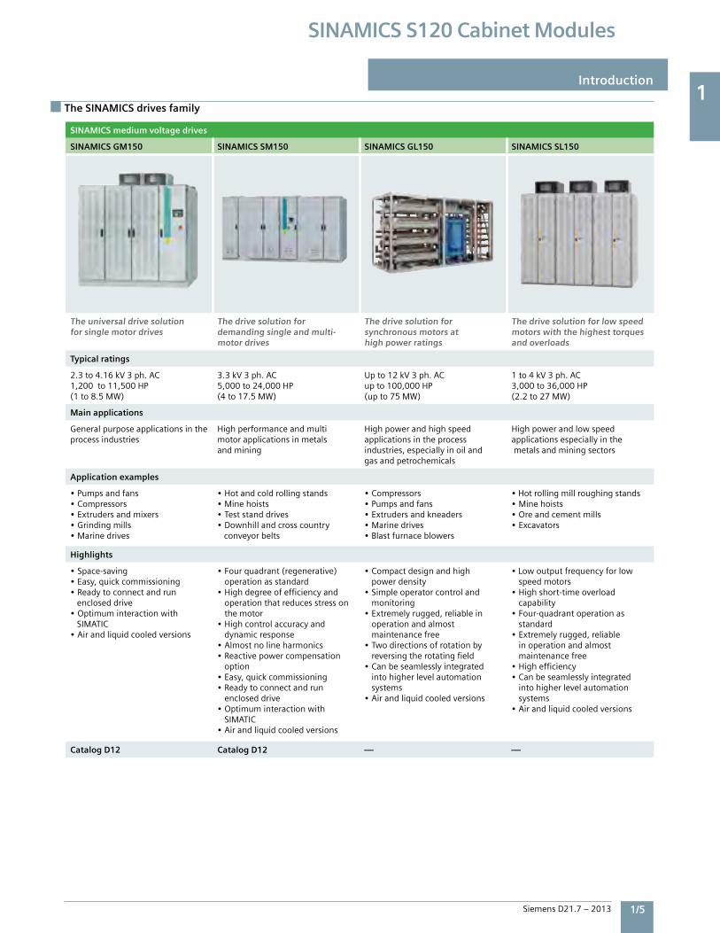
SINAMICS GM150 SINAMICS SM150 SINAMICS GL150 SINAMICS SL150
The universal drive solution for single motor drives
The drive solution for demanding single and multi-motor drives
The drive solution for synchronous motors at high power ratings
The drive solution for low speed motors with the highest torques and overloads
Typical ratings
2.3to4.16kV3ph.AC1,200to11,500HP(1to8.5MW)
3.3kV3ph.AC5,000to24,000HP(4to17.5MW)
Upto12kV3ph.ACupto100,000HP(upto75MW)
1to4kV3ph.AC3,000to36,000HP(2.2to27MW)
Main applications
Generalpurposeapplicationsintheprocessindustries
Highperformanceandmultimotorapplicationsinmetalsandmining
Highpowerandhighspeedapplicationsintheprocessindustries,especiallyinoilandgasandpetrochemicals
Highpowerandlowspeedapplicationsespeciallyinthemetalsandminingsectors
Application examples
•Pumpsandfans•Compressors•Extrudersandmixers•Grindingmills•Marinedrives
•Hotandcoldrollingstands•Minehoists•Teststanddrives•Downhillandcrosscountry conveyorbelts
•Compressors•Pumpsandfans•Extrudersandkneaders•Marinedrives•Blastfurnaceblowers
•Hotrollingmillroughingstands•Minehoists•Oreandcementmills•Excavators
Highlights
•Space-saving•Easy,quickcommissioning•Readytoconnectandrunencloseddrive•OptimuminteractionwithSIMATIC•Airandliquidcooledversions
•Fourquadrant(regenerative) operationasstandard•Highdegreeofefficiencyand operationthatreducesstresson themotor•Highcontrolaccuracyand dynamicresponse•Almostnolineharmonics•Reactivepowercompensation option•Easy,quickcommissioning•Readytoconnectandrun encloseddrive•Optimuminteractionwith SIMATIC•Airandliquidcooledversions
•Compactdesignandhigh powerdensity•Simpleoperatorcontroland monitoring•Extremelyrugged,reliablein operationandalmost maintenancefree•Twodirectionsofrotationby reversingtherotatingfield•Canbeseamlesslyintegrated intohigherlevelautomation systems•Airandliquidcooledversions
•Lowoutputfrequencyforlow speedmotors•Highshort-timeoverload capability•Four-quadrantoperationas standard•Extremelyrugged,reliable inoperationandalmost maintenancefree•Highefficiency•Canbeseamlesslyintegrated intohigherlevelautomation systems•Airandliquidcooledversions
Catalog D12 Catalog D12 — —
Introduction
1
1/6 Siemens D21.7 – 2013
SINAMICS S120 Cabinet Modules
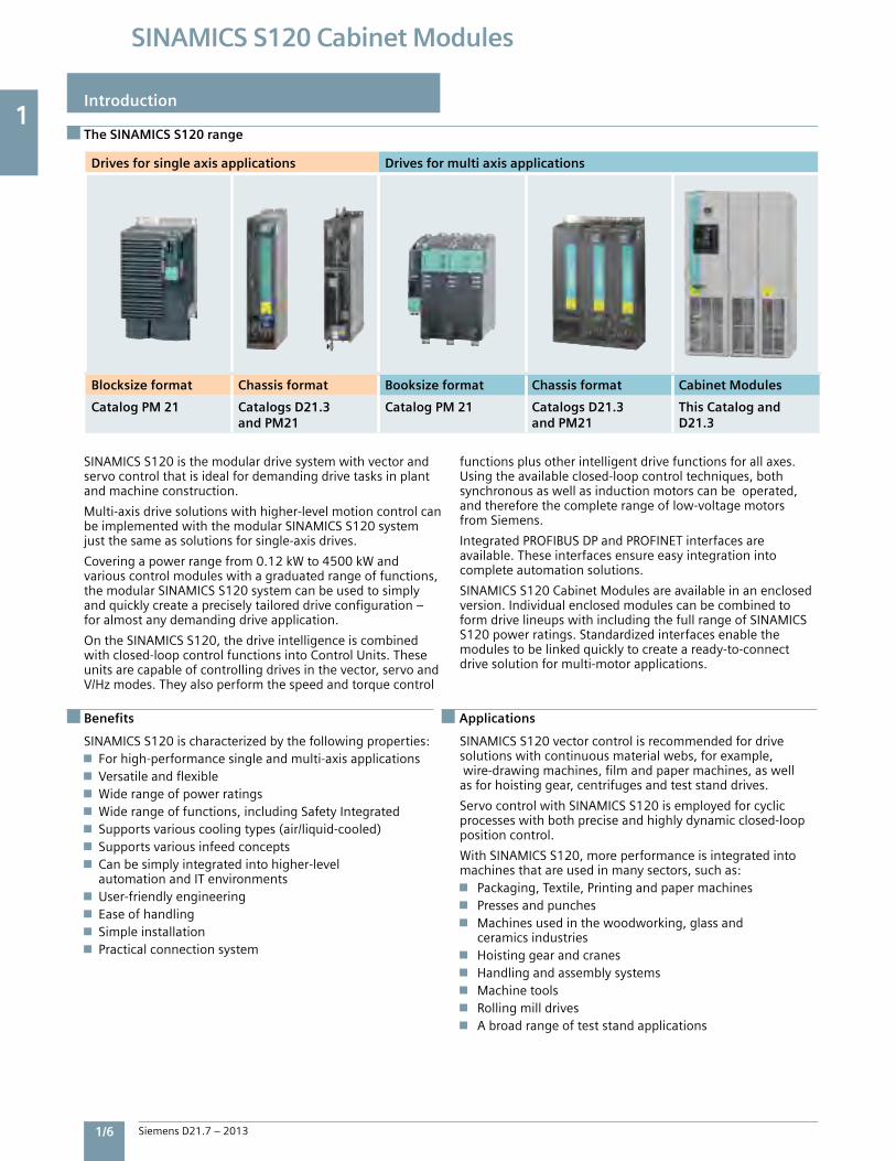
Drives for single axis applications Drives for multi axis applications
Blocksize format Chassis format Booksize format Chassis format Cabinet Modules
Catalog PM 21 Catalogs D21.3 and PM21
Catalog PM 21 Catalogs D21.3 and PM21
This Catalog and D21.3
The SINAMICS S120 range
Introduction
SINAMICSS120isthemodulardrivesystemwithvectorandservocontrolthatisidealfordemandingdrivetasksinplantandmachineconstruction.
Multi-axisdrivesolutionswithhigher-levelmotioncontrolcanbeimplementedwiththemodularSINAMICSS120systemjustthesameassolutionsforsingle-axisdrives.
Coveringapowerrangefrom0.12kWto4500kWandvariouscontrolmoduleswithagraduatedrangeoffunctions,themodularSINAMICSS120systemcanbeusedtosimplyandquicklycreateapreciselytailoreddriveconfiguration–foralmostanydemandingdriveapplication.
OntheSINAMICSS120,thedriveintelligenceiscombinedwithclosed-loopcontrolfunctionsintoControlUnits.Theseunitsarecapableofcontrollingdrivesinthevector,servoandV/Hzmodes.Theyalsoperformthespeedandtorquecontrol
functionsplusotherintelligentdrivefunctionsforallaxes.Usingtheavailableclosed-loopcontroltechniques,bothsynchronousaswellasinductionmotorscanbeoperated,andthereforethecompleterangeoflow-voltagemotorsfromSiemens.
IntegratedPROFIBUSDPandPROFINETinterfacesareavailable.Theseinterfacesensureeasyintegrationintocompleteautomationsolutions.
SINAMICSS120CabinetModulesareavailableinanenclosedversion.IndividualenclosedmodulescanbecombinedtoformdrivelineupswithincludingthefullrangeofSINAMICSS120powerratings.Standardizedinterfacesenablethemodulestobelinkedquicklytocreateaready-to-connectdrivesolutionformulti-motorapplications.
SINAMICSS120ischaracterizedbythefollowingproperties:Forhigh-performancesingleandmulti-axisapplicationsVersatileandflexibleWiderangeofpowerratingsWiderangeoffunctions,includingSafetyIntegratedSupportsvariouscoolingtypes(air/liquid-cooled)SupportsvariousinfeedconceptsCanbesimplyintegratedintohigher-level
automationandITenvironmentsUser-friendlyengineeringEaseofhandlingSimpleinstallationPracticalconnectionsystem
SINAMICSS120vectorcontrolisrecommendedfordrivesolutionswithcontinuousmaterialwebs,forexample,wire-drawingmachines,filmandpapermachines,aswellasforhoistinggear,centrifugesandteststanddrives.
ServocontrolwithSINAMICSS120isemployedforcyclicprocesseswithbothpreciseandhighlydynamicclosed-looppositioncontrol.
WithSINAMICSS120,moreperformanceisintegratedintomachinesthatareusedinmanysectors,suchas:
Packaging,Textile,Printingandpapermachines Pressesandpunches Machinesusedinthewoodworking,glassand
ceramicsindustries Hoistinggearandcranes Handlingandassemblysystems Machinetools Rollingmilldrives Abroadrangeofteststandapplications
Benefits Applications
5
SINAMICS S120 Cabinet ModulesSystem Overview
2/2 Overview of SINAMICS S120 Cabinet Modules
2/3 SINAMICS S120 Cabinet Modules – A Global Product SINAMICSS120CabinetModule designstoNEMAvstoIECstandards
2/4 SINAMICS S120 Cabinet Modules – NEMA/UL version Overviewofvoltageandpowerratings
2/4 UL listing of a SINAMICS S120 Cabinet Module line-up
2/5 System configuration guidelines Selectionandbasicconfigurationof CabinetModules Arrangingmodulesinaline-up SpecifyingtheDCbus Transportsections Optionsapplicabletotheline-up Documentationandintegration engineering
2/7 System design considerations
2/7 Benefits
2
SiemensD21.7–2013
2
2/2 Siemens D21.7 – 2013
SINAMICS S120 Cabinet Modules
System overview
Overview of SINAMICS S120 Cabinet Modules
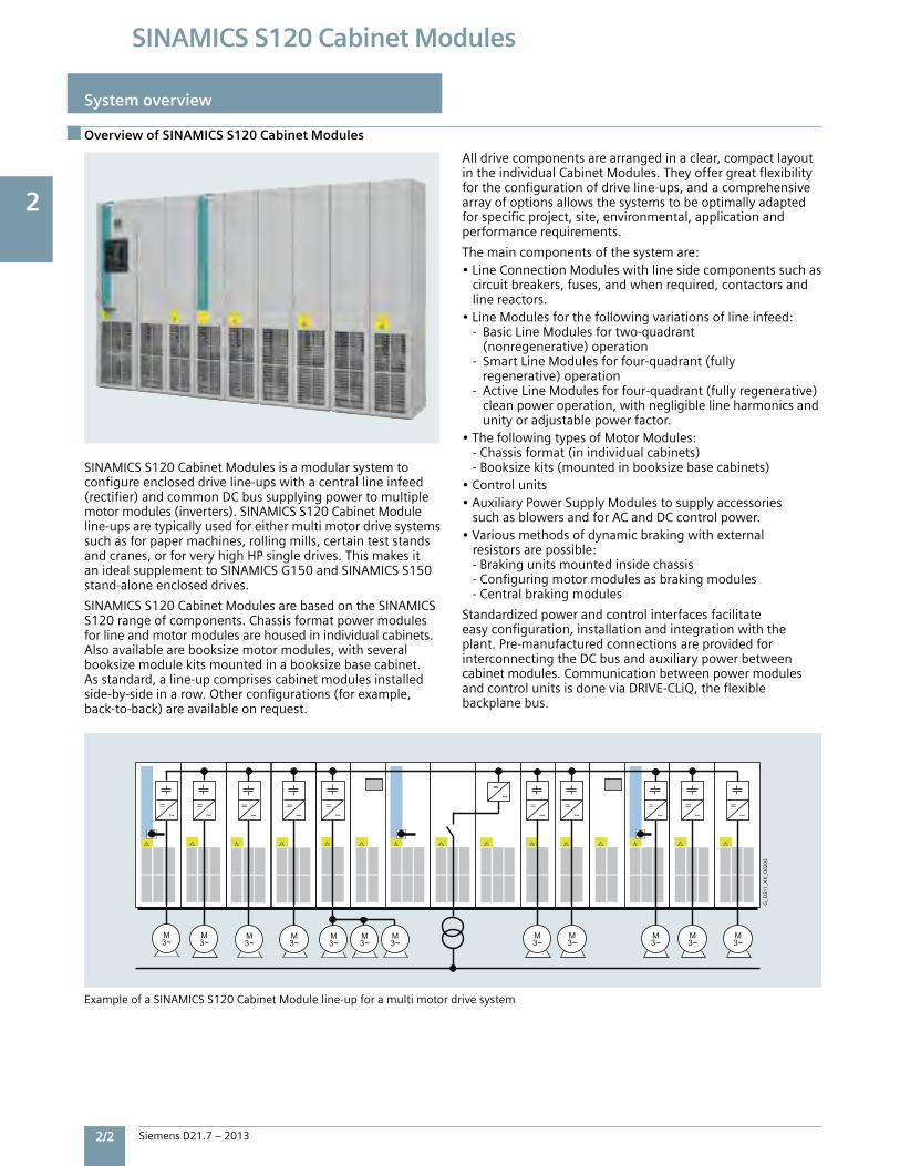
SINAMICSS120CabinetModulesisamodularsystemtoconfigureencloseddriveline-upswithacentrallineinfeed(rectifier)andcommonDCbussupplyingpowertomultiplemotormodules(inverters).SINAMICSS120CabinetModuleline-upsaretypicallyusedforeithermultimotordrivesystemssuchasforpapermachines,rollingmills,certainteststandsandcranes,orforveryhighHPsingledrives.ThismakesitanidealsupplementtoSINAMICSG150andSINAMICSS150stand-aloneencloseddrives.
SINAMICSS120CabinetModulesarebasedontheSINAMICSS120rangeofcomponents.Chassisformatpowermodulesforlineandmotormodulesarehousedinindividualcabinets.Alsoavailablearebooksizemotormodules,withseveralbooksizemodulekitsmountedinabooksizebasecabinet.Asstandard,aline-upcomprisescabinetmodulesinstalledside-by-sideinarow.Otherconfigurations(forexample,back-to-back)areavailableonrequest.
Alldrivecomponentsarearrangedinaclear,compactlayoutintheindividualCabinetModules.Theyoffergreatflexibilityfortheconfigurationofdriveline-ups,andacomprehensivearrayofoptionsallowsthesystemstobeoptimallyadaptedforspecificproject,site,environmental,applicationandperformancerequirements.
Themaincomponentsofthesystemare:•LineConnectionModuleswithlinesidecomponentssuchas circuitbreakers,fuses,andwhenrequired,contactorsand linereactors.•LineModulesforthefollowingvariationsoflineinfeed: - BasicLineModulesfortwo-quadrant (nonregenerative)operation - SmartLineModulesforfour-quadrant(fully regenerative)operation -ActiveLineModulesforfour-quadrant(fullyregenerative) cleanpoweroperation,withnegligiblelineharmonicsand unityoradjustablepowerfactor.•ThefollowingtypesofMotorModules: -Chassisformat(inindividualcabinets) -Booksizekits(mountedinbooksizebasecabinets)•Controlunits•AuxiliaryPowerSupplyModulestosupplyaccessories suchasblowersandforACandDCcontrolpower.•Variousmethodsofdynamicbrakingwithexternal resistorsarepossible: -Brakingunitsmountedinsidechassis -Configuringmotormodulesasbrakingmodules -Centralbrakingmodules
Standardizedpowerandcontrolinterfacesfacilitateeasyconfiguration,installationandintegrationwiththeplant.Pre-manufacturedconnectionsareprovidedforinterconnectingtheDCbusandauxiliarypowerbetweencabinetmodules.CommunicationbetweenpowermodulesandcontrolunitsisdoneviaDRIVE-CLiQ,theflexiblebackplanebus.
ExampleofaSINAMICSS120CabinetModuleline-upforamultimotordrivesystem
=~
M3~
=~
=~
=~
=~
=~
=~
=~
=~
=~
=~
G_
D21
1_X
X_0
0203
M3~
M3~
M3~
M3~
M3~
M3~
M3~
M3~
M3~
M3~
M3~
2
Siemens D21.7 – 2013 2/3
SINAMICS S120 Cabinet Modules
System overview
SINAMICS S120 Cabinet Modules – A Global Product
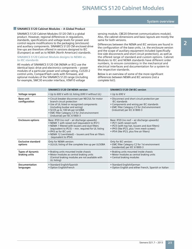
SINAMICSS120CabinetModules(S120CM)isaglobalproduct.However,regionaldifferencesinregulations,standards,specificationsandvoltagelevelsforpowerandcontrolrequiremodificationstothepackaging(enclosure)andauxiliarycomponents.SINAMICSS120CMencloseddriveline-upsarethereforeofferedinversionsdesignedtoIEC(European)aswellastoNEMA(NorthAmerican)standards.
SINAMICS S120 Cabinet Module designs to NEMA vs. to IEC standards
AllmodelsofSINAMICSS120CM(NEMAorIEC)usetheidenticalbasicdriveandelectronicscomponents–powermodulesofaparticularpowerandvoltagerating,CU320-2controlunits,CompactFlashcardswithfirmware,andoptionalmodulesoftheSINAMICSS120range(includingforexample,SMC30encoderinterface,VSM10voltage
sensingmodule,CBE20Ethernetcommunicationsmodule).Also,thecabinetdimensionsandbasiclayoutsaremostlythesameforbothversions.
DifferencesbetweentheNEMAandIECversionsarefoundintheconfigurationofthebaseunits,i.e.theenclosureversionandthescopeofauxiliaryequipmentincluded(specificallylinesidedisconnectsandshortcircuitprotection),aswellastheofferedrangeofstandardandcustomoptions.CabinetModulestoIECandNEMAstandardshavedifferentordernumbers,toensureconsistencyinthemechanicalandelectricalinterfacesanddocumentationforasystemtotherespectivestandards.
BelowisanoverviewofsomeofthemoresignificantdifferencesbetweenNEMAandIECversions(notacompletelist!).
SINAMICS S120 CM NEMA version SINAMICS S120 CM IEC version
Voltage ranges •Upto600VwithULlisting(690VwithoutUL) •Upto690V
Base unit configuration
•CircuitbreakerdisconnectperNEC/ULformotorbranchcircuitprotection•UseofULlistedorrecognizedcomponents(includingbusbarandwiring)•SCCRupto100kAperUL508A•EMCfilterCategoryC3for2ndenvironment (industrial)perIEC61800-3
•Disconnectandshortcircuitprotectionper IECstandards•ComponentsandwiringperIECstandards•EMCfilterCategoryC3for2ndenvironment (industrial)perIEC61800-3
Enclosure options Base:IP20(noroof–airdischargeupwards)•NEMA1withraisedroof(equivalenttoIP21)•NEMA1filteredwithlouversanddustfilters (equivalenttoIP23)–min.requiredforULlisting•IP43asforIECunit•NEMA12(ventilated)–louversandfineairfilters (equivalenttoIP54)
Base:IP20(noroof–airdischargeupwards)•IP21(withraisedroof)•IP23(withtophat,louversanddustfilters)•IP43(likeIP23,plus1mmmeshscreen)•IP54(likeIP23,plusfineairfilters)
Exclusive standard options
OnlyforNEMAversion:•UL/cULlistingofthecompleteline-upperUL508A
OnlyforIECversion:•EMCfilterCategoryC2for1stenvironment (residential)perIEC61800-3
Types of dynamicbraking units
•Brakingunitsmountedinsidechassis•Motormodulesascentralbrakingunits (Centralbrakingmodulesarenotavailablewith ULlisting)
•Brakingunitsmountedinsidechassis•Motormodulesascentralbrakingunits•Centralbrakingmodules
Documentation languages
•StandardEnglish/Spanish•OptionEnglish/French
•StandardEnglish/German•OptionEnglishandeitherFrench,SpanishorItalian
2
2/4 Siemens D21.7 – 2013
SINAMICS S120 Cabinet Modules
System overview
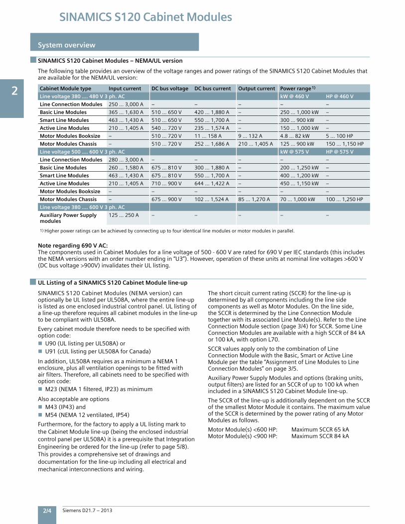
SINAMICS S120 Cabinet Modules – NEMA/UL version
UL Listing of a SINAMICS S120 Cabinet Module line-up
The following table provides an overview of the voltage ranges and power ratings of the SINAMICS S120 Cabinet Modules that are available for the NEMA/UL version:
Note regarding 690 V AC:The components used in Cabinet Modules for a line voltage of 500 - 600 V are rated for 690 V per IEC standards (this includes the NEMA versions with an order number ending in “U3”). However, operation of these units at nominal line voltages >600 V (DC bus voltage >900V) invalidates their UL listing.
SINAMICS S120 Cabinet Modules (NEMA version) can optionally be UL listed per UL508A, where the entire line-up is listed as one enclosed industrial control panel. UL listing of a line-up therefore requires all cabinet modules in the line-up to be compliant with UL508A.
Every cabinet module therefore needs to be specified withoption code:n U90 (UL listing per UL508A) ornU91 (cUL listing per UL508A for Canada)
In addition, UL508A requires as a minimum a NEMA 1enclosure, plus all ventilation openings to be fitted with air filters. Therefore, all cabinets need to be specified with option code:nM23 (NEMA 1 filtered, IP23) as minimum
Also acceptable are optionsnM43 (IP43) andnM54 (NEMA 12 ventilated, IP54)
Furthermore, for the factory to apply a UL listing mark to the Cabinet Module line-up (being the enclosed industrial control panel per UL508A) it is a prerequisite that Integration Engineering be ordered for the line-up (refer to page 5/8). This provides a comprehensive set of drawings and documentation for the line-up including all electrical and mechanical interconnections and wiring.
The short circuit current rating (SCCR) for the line-up is determined by all components including the line side components as well as Motor Modules. On the line side, the SCCR is determined by the Line Connection Module together with its associated Line Module(s). Refer to the Line Connection Module section (page 3/4) for SCCR. Some Line Connection Modules are available with a high SCCR of 84 kA or 100 kA, with option L70.
SCCR values apply only to the combination of Line Connection Module with the Basic, Smart or Active LineModule per the table “Assignment of Line Modules to LineConnection Modules” on page 3/5.
Auxiliary Power Supply Modules and options (braking units, output filters) are listed for an SCCR of up to 100 kA when included in a SINAMICS S120 Cabinet Module line-up.
The SCCR of the line-up is additionally dependent on the SCCR of the smallest Motor Module it contains. The maximum value of the SCCR is determined by the power rating of any Motor Modules as follows.
Motor Module(s) <600 HP: Maximum SCCR 65 kAMotor Module(s) <900 HP: Maximum SCCR 84 kA
Cabinet Module type Input current DC bus voltage DC bus current Output current Power range 1)
Line voltage 380 …. 480 V 3 ph. AC kW @ 460 V HP @ 460 V
Line Connection Modules 250 … 3,000 A – – – – –
Basic Line Modules 365 … 1,630 A 510 … 650 V 420 … 1,880 A – 250 … 1,000 kW –
Smart Line Modules 463 … 1,430 A 510 … 650 V 550 … 1,700 A – 300 … 900 kW –
Active Line Modules 210 … 1,405 A 540 … 720 V 235 … 1,574 A – 150 … 1,000 kW –
Motor Modules Booksize – 510 … 720 V 11 ... 158 A 9 ... 132 A 4.8 ... 82 kW 5 ... 100 HP
Motor Modules Chassis – 510 … 720 V 252 … 1,686 A 210 … 1,405 A 125 … 900 kW 150 … 1,150 HP
Line voltage 500 …. 600 V 3 ph. AC kW @ 575 V HP @ 575 V
Line Connection Modules 280 … 3,000 A – – – – –
Basic Line Modules 260 … 1,580 A 675 … 810 V 300 … 1,880 A – 200 … 1,250 kW –
Smart Line Modules 463 … 1,430 A 675 … 810 V 550 … 1,700 A – 400 … 1,200 kW –
Active Line Modules 210 … 1,405 A 710 … 900 V 644 … 1,422 A – 450 … 1,150 kW –
Motor Modules Booksize – – – – – –
Motor Modules Chassis – 675 … 900 V 102 … 1,524 A 85 … 1,270 A 70 … 1,000 kW 100 … 1,250 HP
Line voltage 380 …. 600 V 3 ph. AC
Auxiliary Power Supply modules
125 ... 250 A – – – – –
1) Higher power ratings can be achieved by connecting up to four identical line modules or motor modules in parallel.
2
Siemens D21.7 – 2013 2/5
SINAMICS S120 Cabinet Modules
System overview
System configuration guidelines
SINAMICSS120CabinetModulesisamodularsystem,whereindividualCabinetModulesarecombinedintoanencloseddriveline-up.Thesystemprovidesagreatdealofflexibilityandtogetherwithalargevarietyofoptionsallowsanalmostinfinitenumberofpossiblepermutations.Toensurethattheendresultisafullyfunctioningsysteminaccordancewithrequirements,variousaspectsneedtobeconsideredintheselectionandconfigurationofindividualcabinetmodules,andwhenspecifyinghowthesearetobecombinedintoaline-up.
Selection and basic configuration of cabinet modules
nMotorModulesdrawpowerfromorgeneratepowertothe DCbus,andsupplyvariablevoltageandfrequencytoone ormoremotors.Theyareselectedbasedonmotorratings andoverloads,applicationspecificdutycyclesetc.Motor Modulesareavailableintwoformats: -Chassisformat,witheachchassisinitsowncabinet. -Booksizeformat,whereBooksizeBaseCabinetscontain anumberofbooksizemodulekits.nLineModulesfeedpowertotheDCbus.Theyareselected basedonthepowertobedrawnfromorregeneratedinto thesupplysystem. -BasicLineModulesformotoringonly. -SmartorActiveLineModulesifpowerregenerationback tothelineisnecessary. -Theoverallpowerbalancemustbeconsidered,for example,somemotorsmaybemotoringwhileothers areregenerating.Theenergywouldbeexchangedon theDCbusandnotnecessarilybacktotheline,sothe linemoduleisoftennotsizedtoprovidethesumofthe motormoduleratings.Onlyexcesspowerisregenerated backtotheline. - Iftheratioofpowerregeneratedtothelineissmall comparedtothemotoringpowerdrawnfromtheline, specialconfigurationssuchasamixofBasicandSmart LineModulesmaybeappropriate.(Consultfactory).nBrakingunitsfordynamicbrakingdissipateexcessDCbus powerinbrakingresistors.Theymaybeneeded: - Eitherasanalternativetoregenerationtotheline -Or,insomeapplicationssuchasdownhillconveyors,in additiontoregenerationtoallowelectricalbrakinginthe eventofapowerfailure.nLineConnectionModulesconnectLineModulestothe ACpowersupply,andcontainataminimum,themain circuitbreakerdisconnectandusuallythesemiconductor fusesasrequiredfortheshortcircuitcurrentrating(SSCR) oftheline-up.Theyareselectedandconfiguredtomatch thechosenLineModules.Thisrequirescloseattentionto ensurethatthecorrectACbusinterconnectionsand necessarycomponentsareprovided. - BasicandSmartLineModulesgenerallyrequirespecific linereactors,activelinemodulesdonot. -CertainLineModules(dependingontypeandrating) requireacontactororamaincircuitbreakertobridge (bypass)thepre-chargecircuit,andtoswitchtheline moduleonlineaftercompletionofprecharge.nAuxiliaryPowerSupplyModulessupplyauxiliaryand controlpowertotheline-up,forexample3-phaseand singlephaseACpowerforthepowermoduleblowers,
contactorcoilsandmotorizedcircuitbreakers,and24VDC topowercontrolunitsandotherelectronics.Auxiliary powerterminalblocksareprovidedineachcabinet module,withapre-manufacturedcableloopingauxiliary powerfromonecabinetmoduletothenext. -TheAuxiliaryPowerSupplyModuleisselectedbasedon thetotalpowerrequirementoftheline-up. -Forsmallline-ups,auxiliarypowersuppliescanbe providedintheLineConnectionModule(optionsK70 orK76). -Itisalsopossibletoprovideauxiliarypowerfromexternal sources.Thisisthedefault–auxiliarypowerwillbe providedinternallyonlyifspecified!
Arranging Cabinet Modules in a line-up
AftertheCabinetModulesareselected,theyneedtobearrangedinaline-up,normallyinastraightlinenexttoeachother.Suchaline-upcanbemountedagainstawall(CabinetModulesrequirefrontaccessonly).Customconfigurations(suchasback-to-back)canalsobeoffered.DCbusconnectionsforback-to-backarrangementscanbemadeattheendofaline-uporinthemiddle,insomeinstanceswithoutrequiringanyadditionalcabinet.
Variousissuesneedtobeconsideredwhendeterminingthelayoutoftheline-up:nALineModuleisalwayspositionedadjacenttoandonthe righthandsideofitsassociatedsingleLineConnection Module(whenlookingatthefrontofthelineup).Line ConnectionModulesforparallelconnectionhavethe associatedLineModulesoneitherside.nLineModulesareoftenpositionedtowardsthecenterof theline-up.ThisprovidesforhalfthetotalDCbuspower tobefedineachdirection(andthereforehalftheDCbus cross-section),incontrasttotheDCbushavingtocarry fullcurrentiftheLineModuleisatoneendofaline-up.nThelargestMotorModulesshouldpreferablybeclosest totheLineModule.ThismayallowtheDCbussizeto bereducedfurtherdowntheline-upwherelesspower isrequired.nMotorModulesthatfeedpairsofmotorswhereone ismotoringwhiletheotherisregenerating(e.g. winders/unwindersorsometeststands)shouldpreferably bepositionedadjacenttoeachother,tominimizetheDC buscurrentelsewhereintheline-up.nBrakingModulesshouldbepositionedascloseaspossible tothemotormodule(s)regeneratingthemostpower.nForprocess,plantlayoutorcablingdesignreasons,there maybeapreferencetopositioncertaindrivesina sequence,oratleastadjacenttoeachotheringroups. Suchpreferencesmayneedtobebalancedagainstthe considerationslistedabove,inordertoobtainthebest technicalandmostcosteffectivesolution.
ThepositioningofCabinetModulesinaline-upisthereforeoftenaniterativeprocess.
Cabinet Module type Input current DC bus voltage DC bus current Output current Power range 1)
Line voltage 380 …. 480 V 3 ph. AC kW @ 460 V HP @ 460 V
Line Connection Modules 250…3,000A – – – – –
Basic Line Modules 365…1,630A 510…650V 420…1,880A – 250…1,000kW –
Smart Line Modules 463…1,430A 510…650V 550…1,700A – 300…900kW –
Active Line Modules 210…1,405A 540…720V 235…1,574A – 150…1,000kW –
Motor Modules Booksize – 510…720V 11...158A 9...132A 4.8...82kW 5...100HP
Motor Modules Chassis – 510…720V 252…1,686A 210…1,405A 125…900kW 150…1,150HP
Line voltage 500 …. 600 V 3 ph. AC kW @ 575 V HP @ 575 V
Line Connection Modules 280…3,000A – – – – –
Basic Line Modules 260…1,580A 675…810V 300…1,880A – 200…1,250kW –
Smart Line Modules 463…1,430A 675…810V 550…1,700A – 400…1,200kW –
Active Line Modules 210…1,405A 710…900V 644…1,422A – 450…1,150kW –
Motor Modules Booksize – – – – – –
Motor Modules Chassis – 675…900V 102…1,524A 85…1,270A 70…1,000kW 100…1,250HP
Line voltage 380 …. 600 V 3 ph. AC
Auxiliary Power Supply modules
125...250A – – – – –
1)Higherpowerratingscanbeachievedbyconnectinguptofouridenticallinemodulesormotormodulesinparallel.
2
2/6 Siemens D21.7 – 2013
SINAMICS S120 Cabinet Modules
System overview
System configuration guidelines
Specifying the DC bus for each Cabinet Module
OncethearrangementofCabinetModulesisknown,andwithathoroughunderstandingoftheDCcurrentdemand(motoringorgenerating)ofthevariousMotorModulesbasedontheprocesstobecontrolled,therequiredDCbuscurrentratingcanbedeterminedforeachcabinetmodule.nTheDCbusratingisamandatoryoptionforallLineand MotorModules.nForLineConnectionandAuxiliaryPowerSupplyModules aDCbusisoptional.Ifthesemodulesarepositionedatthe endofaline-uptheymaynotneedaDCbus.However,if thereareMotorand/orLineModulestoeitherside,thena DCbusmaybeneeded.nTheDCbusisavailableindifferentwidths(60,80or100 mm)anddependantoncurrentratingwitheitherasingle busbarperpole,ortwoorthreebusbarsinparallel. - Onlybusbarsofthesamewidthcanbeinterconnected. ThereforeallDCbusinaline-upmustbeofthe samewidth. -ForreducedDCbuscurrentratingsalongaline-up,itis possibletochangefromsaythreeparallelbusbarsdown totwo,andthendowntoasingleone.nFortheinterconnectionoftheDCbusfromonecabinet (orsectionofaline-up)toanadjacentone,standardbus transitionpiecesareprovided.Thesearepermanently mounted.Duringinstallationthetransitionpiecesslide intothenextbussectionandonlyneedtobetightened.
Combining Cabinet Modules into transport sections
EachCabinetModuleisspecifiedindividually.ItispossibleforeachCabinetModuletoalsobeshippedindividually,eachoneonitsownpallet,eachwithitsownpieceofDCbusasspecifiedpertheoptioncodes.nItisimportanttonotethatevenifCabinetModulesare shippedindividually,theyneedtobeinstalledinthe arrangementasperthespecifiedline-updesign.Thisis especiallythecaseiftheDCbusratingvariesalongthe line-up.Butthereareusuallyalsoothercomponents (suchasDRIVE-CLiQcables)thatwereselectedbasedon aspecificconfiguration.
Itis,however,morecommontocombineCabinetModulesintotransportsections:nTwoormoreCabinetModulesareboltedtogetherona commonpallet,andarefittedwithacommontransport beam.Themaximumwidthofeachtransportsectionis 2,400mm(approx.8ft).Transportsectionsarespecified byoptionY11,withacodetospecifythepositionofa CabinetModulewithintheline-up.nNormally,theDCbusforeachtransportsectionis providedasasolidbusrunningitsentirelength. - Thisminimizesthenumberofboltedconnections, simplifyinginstallationandmaintenance. -Aconsequenceofthisisthatitisnotpossibletochange thepositionofindividualCabinetModuleswithina line-upatalaterstage.nAuxiliarypowerconnectionsbetweencabinetsinone transportsectionareautomaticallydoneinthefactory.
Cabinet Module options applicable to a whole line-up
WitheachCabinetModulebeingspecifiedindividually,itisnecessarytoensurethattheyareallcompatibleandcanbecombinedinoneline-up.Examplesofoptionsapplicabletoallmodulesinalineupinclude:nEnclosuretype(NEMA1,NEMA1filtered,NEMA12).nCabinetbase(plinth):AllCabinetModulesmusthavethe sameoverallheight.nULorcULlisting–thecompleteline-upiseitherULlisted perUL508Aornot.Itisnotpossibletohaveonlysomeof theCabinetModulesULlisted,butothersnot.nDocumentationformatandlanguagesshouldbethesame forallmodules.Documentationoptionscanbespecified foreachCabinetModuleindividually,orfortheline-upas awhole(refertofollowingparagraph).
Documentation and Integration Engineering
IncludedwitheachindividualCabinetModuleisasetofdrawingsanddocumentation(inelectronicformat(pdf),shippedonaCDwiththeCabinetModule).Asadefaultthereis,however,nodocumentationforthecompleteline-upshowinginterconnectionsbetweenCabinetModules.ThereasonisthatthefactorycannotdeducehowthevariousCabinetModulesareintendedtofunction,basedontheindividualpartnumbers.Forexample,theremaybeanumberofMotorModuleswithonlysomeincludingacontrolunit,whichcouldbeconnectedinmanydifferentways.Onecontrolunitcouldbeusedtocontrolanumberofpowermodules,eachforadifferentmotororsomepowermodulescouldbeintendedforparallelconnection.Andthereisnowaytotellwhichcontrolunitistobeconnectedtowhichpowermodule(s).
“IntegrationEngineering”tointegratetheindividualCabinetModulesintoonefunctioningline-upcanbeprovided,basedonadetailedcustomerspecification.Thisincludes:nDocumentationfortheline-upasawhole,withallinternal interconnectionsrequiredforafunctioningsystem.nProvisionofalltheinterconnectionssuchasDRIVE-CLiQ cablesandotherwiringtoachievethespecified functionality.
IntegrationEngineeringcanbeorderedusingseparatepartnumbers.Documentationoptioncodes(dxfformat,advance(submittal)copiesetc.)canbeaddedtotheorderno.forintegrationengineeringfortheline-upasawhole,insteadofbeingaddedtotheorderno.foreachindividualCabinetModule.
Notethatinthiscontext“IntegrationEngineering”islimitedonlytointegratingindividualCabinetModulesintoaline-up.Thisisnottobeconfusedwithintegrationofthedrivelineupintothecustomer’splantandinterconnectiontoexternalequipmentsuchaspowersupplies,motorsandprocesscontrolorautomationequipment,whichisoutsidethescopeofsupplyofaCabinetModuleline-up!
2
Siemens D21.7 – 2013 2/7
SINAMICS S120 Cabinet Modules
System overview
System design considerations
Benefits
SINAMICSS120CabinetModuleshavebeendesignedtoofferthehighestpossiblelevelofoperationalreliability.nEMCmeasureshavebeenrigorouslyimplementedto ensuretroublefreeoperationofhighspeeddigital controlandcommunicationsystemsincloseproximity tohighpowerswitchingdevices.nWiththehelpofairflowandtemperaturesimulations, partitionshavebeendesignedtoactasairbafflesand heatsinks.nSpecialmeasuresusedintheconstructionofthecabinets ensurethattheyremainmechanicallydurableovertheir entirelifecycle.nAttentionhasbeenpaidtoprovidingawiderangeof cableroutingoptionsandspecialdesignconceptsare appliedconsistentlytobroadenthescopeofapplication andsimplifyservicing.nTheunitsaresuppliedcompletewithallthenecessary connectionsandconnectingelements.Thankstotheir carefullyconsideredconfigurationconcept,cabinetsare
shippedinaready-to-connectstateor,inthecaseof multipletransportsections,havebeenpreparedfor quickassembly.
Theselectionyoumakeissupportedbyanextensiverangeofoptions,harmonizedandcoordinatedtovariousapplications.
Thedesignofreplaceablecomponentsisbasedontheprinciplethattheymustbequickandeasytochange.Inaddition,the“Spares-On-Web”Internettoolmakesiteasytoviewthesparepartsthatareavailablefortheparticularorder.
Allcomponents,fromindividualpartstotheready-to-connectcabinet,undergorigoroustestingthroughouttheentireproductionprocess.Thisguaranteesahighleveloffunctionalreliabilityduringinstallationandcommissioning,aswellasoperation.
TheoutstandingsystemfeaturesoftheSINAMICSS120CabinetModulesprovidethefollowingadvantages:nPre-designed,typetestedsystem: -Configurationofstandardcatalogproduct minimizesengineering. -Typetested,robustdesignprovidesguaranteed performanceinindustrialenvironments.nHighlevelofreliabilityandavailability: -Powermoduleswithhighratingsminimizecomponent countandmaximizereliability. - Individualmodulesandpowercomponentscanbe replacedquicklyandeasily,whichensuresahigherlevel ofplantavailability.nProcessoptimizationwithminimaleffort: -AstandardPROFIBUSorPROFINETinterfaceandvarious analoganddigitalinterfacesenableeasyintegration intoautomationsolutions. -Vectorcontrolfulfillsthemostexactingrequirements regardingtheaccuracyanddynamicresponseofdrives.nEnergysavingsduringoperation: -Theinvertersonthemotorsidearecoupledthrough acommonDCbuswhichallowsenergyexchange betweenmotorsthataremotoringandgenerating.In thisway,energyissaved,thelineinfeedisrelievedand lineharmonicsreduced.
-Generallythelineinfeedisonlydimensionedforthe maximumenergyorthemaximumcurrentdrawnwhen motoring–andnotthesumoftheenergyratingsofall MotorModulesconnectedtotheDCbus. -Asaconsequence,forexample,forwinders/unwinders ortransmissionteststandswithMotorModulesthatare motoringandgenerating,asignificantlysmallerline infeedunitcanbeselected.nCostminimizationduringoperation,maintenance, andservice: -Simplecommissioningwiththemenu-drivenSTARTER commissioningtool. -Optional,menu-navigatedAOP30advancedoperator panelwithplaintextdisplayandbar-typedisplayof processvalues. -Allcomponentsareeasilyaccessible,whichmakesthem extremelyservicefriendly.nSpace-savingdesign -Optimizedcomponentlayoutsresultinsmallest possiblefootprint.nEnvironmentallyfriendlyoperation: -Thedrivesareexceptionallyquietandcompactdueto theuseofstate-of-the-artIGBTpowersemiconductors andaninnovativecoolingconceptthatensuresa longlifetime.
2
2/8 Siemens D21.7 – 2013
SINAMICS S120 Cabinet Modules
System overviewNotes
5
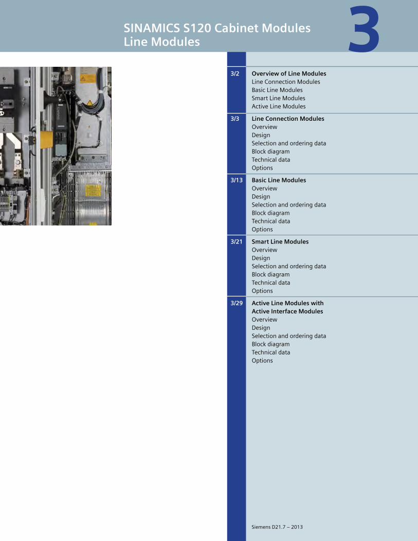
SINAMICS S120 Cabinet ModulesLine Modules
3/2 Overview of Line Modules LineConnectionModules BasicLineModules SmartLineModules ActiveLineModules
3/3 Line Connection Modules Overview Design Selectionandorderingdata Blockdiagram Technicaldata Options
3/13 Basic Line Modules Overview Design Selectionandorderingdata Blockdiagram Technicaldata Options
3/21 Smart Line Modules Overview Design Selectionandorderingdata Blockdiagram Technicaldata Options
3/29 Active Line Modules with Active Interface Modules Overview Design Selectionandorderingdata Blockdiagram Technicaldata Options
3
SiemensD21.7–2013
3
3/2 Siemens D21.7 – 2013
SINAMICS S120 Cabinet Modules
Overview of Line Modules
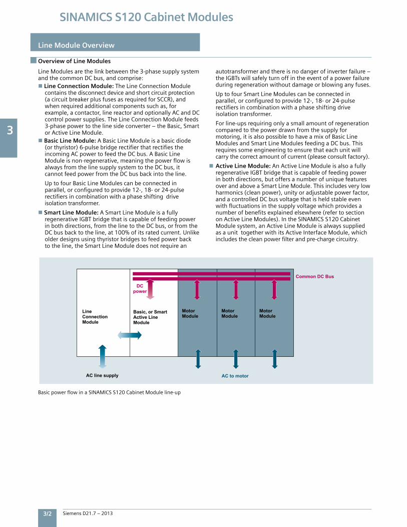
LineModulesarethelinkbetweenthe3-phasesupplysystemandthecommonDCbus,andcomprise:n Line Connection Module:TheLineConnectionModule containsthedisconnectdeviceandshortcircuitprotection (acircuitbreakerplusfusesasrequiredforSCCR),and whenrequiredadditionalcomponentssuchas,for example,acontactor,linereactorandoptionallyACandDC controlpowersupplies.TheLineConnectionModulefeeds 3-phasepowertothelinesideconverter–theBasic,Smart orActiveLineModule.nBasic Line Module:ABasicLineModuleisabasicdiode (orthyristor)6-pulsebridgerectifierthatrectifiesthe incomingACpowertofeedtheDCbus.ABasicLine Moduleisnon-regenerative,meaningthepowerflowis alwaysfromthelinesupplysystemtotheDCbus,it cannotfeedpowerfromtheDCbusbackintotheline.
UptofourBasicLineModulescanbeconnectedin parallel,orconfiguredtoprovide12-,18-or24-pulse rectifiersincombinationwithaphaseshiftingdrive isolationtransformer.
nSmart Line Module:ASmartLineModuleisafully regenerativeIGBTbridgethatiscapableoffeedingpower inbothdirections,fromthelinetotheDCbus,orfromthe DCbusbacktotheline,at100%ofitsratedcurrent.Unlike olderdesignsusingthyristorbridgestofeedpowerback totheline,theSmartLineModuledoesnotrequirean
autotransformerandthereisnodangerofinverterfailure– theIGBTswillsafelyturnoffintheeventofapowerfailure duringregenerationwithoutdamageorblowinganyfuses.
UptofourSmartLineModulescanbeconnectedin parallel,orconfiguredtoprovide12-,18-or24-pulse rectifiersincombinationwithaphaseshiftingdrive isolationtransformer.
Forline-upsrequiringonlyasmallamountofregeneration comparedtothepowerdrawnfromthesupplyfor motoring,itisalsopossibletohaveamixofBasicLine ModulesandSmartLineModulesfeedingaDCbus.This requiressomeengineeringtoensurethateachunitwill carrythecorrectamountofcurrent(pleaseconsultfactory).
nActive Line Module:AnActiveLineModuleisalsoafully regenerativeIGBTbridgethatiscapableoffeedingpower inbothdirections,butoffersanumberofuniquefeatures overandaboveaSmartLineModule.Thisincludesverylow harmonics(cleanpower),unityoradjustablepowerfactor, andacontrolledDCbusvoltagethatisheldstableeven withfluctuationsinthesupplyvoltagewhichprovidesa numberofbenefitsexplainedelsewhere(refertosection onActiveLineModules).IntheSINAMICSS120Cabinet Modulesystem,anActiveLineModuleisalwayssupplied asaunittogetherwithitsActiveInterfaceModule,which includesthecleanpowerfilterandpre-chargecircuitry.
BasicpowerflowinaSINAMICSS120CabinetModuleline-up
Line Module Overview
Common DC Bus
AC to motorAC line supply
DCpower
LineConnectionModule
Basic, or SmartActive LineModule
Motor Module
Motor Module
Motor Module
3
Siemens D21.7 – 2013 3/3
SINAMICS S120 Cabinet Modules
Line Connection Modules – Overview
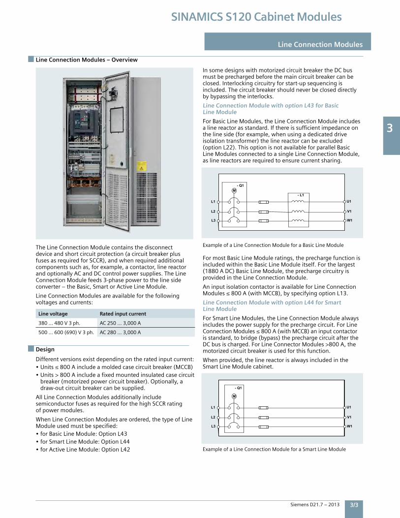
TheLineConnectionModulecontainsthedisconnectdeviceandshortcircuitprotection(acircuitbreakerplusfusesasrequiredforSCCR),andwhenrequiredadditionalcomponentssuchas,forexample,acontactor,linereactorandoptionallyACandDCcontrolpowersupplies.TheLineConnectionModulefeeds3-phasepowertothelinesideconverter–theBasic,SmartorActiveLineModule.
LineConnectionModulesareavailableforthefollowingvoltagesandcurrents:
Line voltage Rated input current
380…480V3ph. AC250…3,000A
500…600(690)V3ph. AC280…3,000A
Design
Differentversionsexistdependingontheratedinputcurrent:•Units≤800Aincludeamoldedcasecircuitbreaker(MCCB)•Units>800Aincludeafixedmountedinsulatedcasecircuit breaker(motorizedpowercircuitbreaker).Optionally,a draw-outcircuitbreakercanbesupplied.
AllLineConnectionModulesadditionallyincludesemiconductorfusesasrequiredforthehighSCCRratingofpowermodules.
WhenLineConnectionModulesareordered,thetypeofLineModuleusedmustbespecified:•forBasicLineModule:OptionL43•forSmartLineModule:OptionL44•forActiveLineModule:OptionL42
InsomedesignswithmotorizedcircuitbreakertheDCbusmustbeprechargedbeforethemaincircuitbreakercanbeclosed.Interlockingcircuitryforstart-upsequencingisincluded.Thecircuitbreakershouldneverbecloseddirectlybybypassingtheinterlocks.
Line Connection Module with option L43 for Basic Line Module
ForBasicLineModules,theLineConnectionModuleincludesalinereactorasstandard.Ifthereissufficientimpedanceonthelineside(forexample,whenusingadedicateddriveisolationtransformer)thelinereactorcanbeexcluded(optionL22).ThisoptionisnotavailableforparallelBasicLineModulesconnectedtoasingleLineConnectionModule,aslinereactorsarerequiredtoensurecurrentsharing.
ExampleofaLineConnectionModuleforaBasicLineModule
FormostBasicLineModuleratings,theprechargefunctionisincludedwithintheBasicLineModuleitself.Forthelargest(1880ADC)BasicLineModule,theprechargecircuitryisprovidedintheLineConnectionModule.
AninputisolationcontactorisavailableforLineConnectionModules≤800A(withMCCB),byspecifyingoptionL13.
Line Connection Module with option L44 for Smart Line Module
ForSmartLineModules,theLineConnectionModulealwaysincludesthepowersupplyfortheprechargecircuit.ForLineConnectionModules≤800A(withMCCB)aninputcontactorisstandard,tobridge(bypass)theprechargecircuitaftertheDCbusischarged.ForLineConnectorModules>800A,themotorizedcircuitbreakerisusedforthisfunction.
Whenprovided,thelinereactorisalwaysincludedintheSmartLineModulecabinet.
ExampleofaLineConnectionModuleforaSmartLineModule
Line Connection Modules
- Q1
M
L1
L2
L3
U1
V1
W1
- Q1M
L1
L2
L3
U1
V1
W1
- L1
3
3/4 Siemens D21.7 – 2013
SINAMICS S120 Cabinet Modules
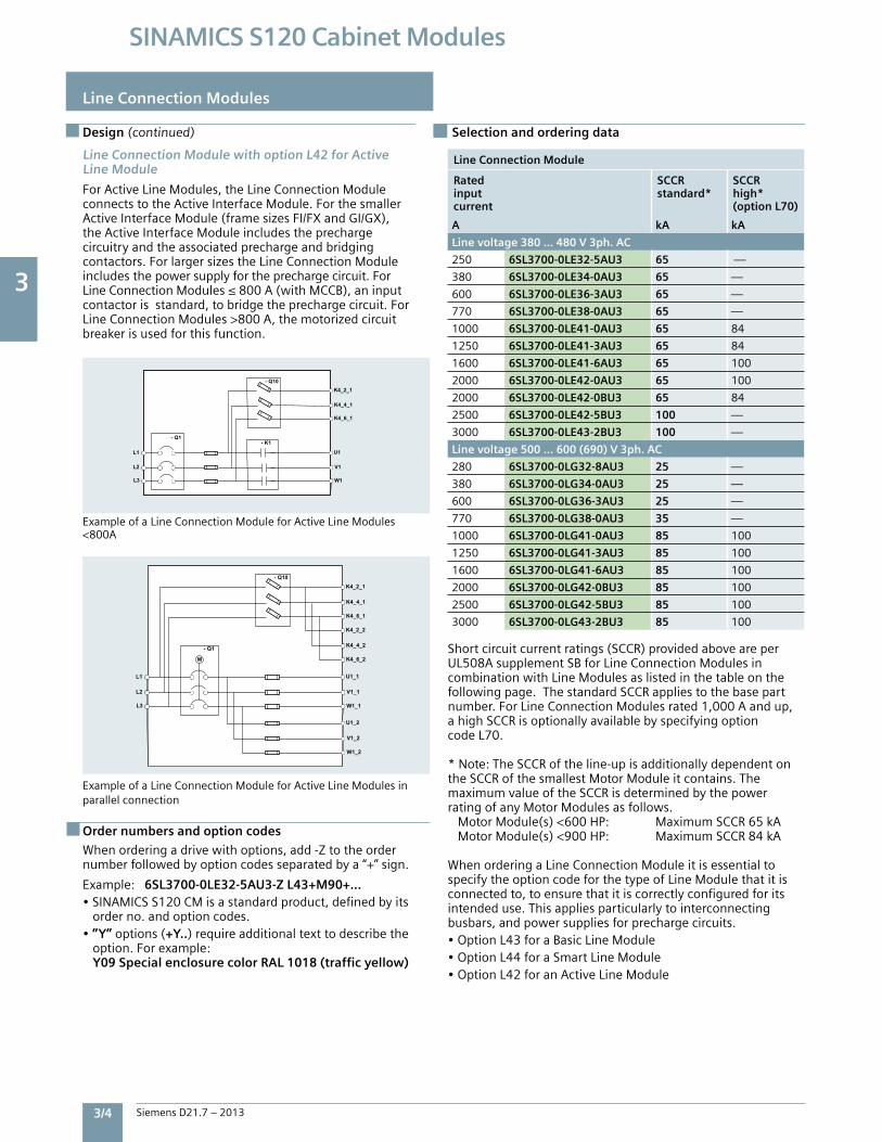
Design (continued) Selection and ordering data
Order numbers and option codes
Line Connection Module with option L42 for Active Line Module
ForActiveLineModules,theLineConnectionModuleconnectstotheActiveInterfaceModule.ForthesmallerActiveInterfaceModule(framesizesFI/FXandGI/GX),theActiveInterfaceModuleincludestheprechargecircuitryandtheassociatedprechargeandbridgingcontactors.ForlargersizestheLineConnectionModuleincludesthepowersupplyfortheprechargecircuit.ForLineConnectionModules≤800A(withMCCB),aninputcontactorisstandard,tobridgetheprechargecircuit.ForLineConnectionModules>800A,themotorizedcircuitbreakerisusedforthisfunction.
ExampleofaLineConnectionModuleforActiveLineModules<800A
ExampleofaLineConnectionModuleforActiveLineModulesinparallelconnection
Whenorderingadrivewithoptions,add-Ztotheordernumberfollowedbyoptioncodesseparatedbya“+”sign.
Example:6SL3700-0LE32-5AU3-Z L43+M90+…•SINAMICSS120CMisastandardproduct,definedbyits orderno.andoptioncodes.•”Y”options(+Y..)requireadditionaltexttodescribethe option.Forexample: Y09 Special enclosure color RAL 1018 (traffic yellow)
Line Connection Module
Ratedinputcurrent
SCCRstandard*
SCCRhigh*(option L70)
A kA kA
Line voltage 380 … 480 V 3ph. AC
250 6SL3700-0LE32-5AU3 65 —
380 6SL3700-0LE34-0AU3 65 —
600 6SL3700-0LE36-3AU3 65 —
770 6SL3700-0LE38-0AU3 65 —
1000 6SL3700-0LE41-0AU3 65 84
1250 6SL3700-0LE41-3AU3 65 84
1600 6SL3700-0LE41-6AU3 65 100
2000 6SL3700-0LE42-0AU3 65 100
2000 6SL3700-0LE42-0BU3 65 84
2500 6SL3700-0LE42-5BU3 100 —
3000 6SL3700-0LE43-2BU3 100 —
Line voltage 500 … 600 (690) V 3ph. AC
280 6SL3700-0LG32-8AU3 25 —
380 6SL3700-0LG34-0AU3 25 —
600 6SL3700-0LG36-3AU3 25 —
770 6SL3700-0LG38-0AU3 35 —
1000 6SL3700-0LG41-0AU3 85 100
1250 6SL3700-0LG41-3AU3 85 100
1600 6SL3700-0LG41-6AU3 85 100
2000 6SL3700-0LG42-0BU3 85 100
2500 6SL3700-0LG42-5BU3 85 100
3000 6SL3700-0LG43-2BU3 85 100
Shortcircuitcurrentratings(SCCR)providedaboveareperUL508AsupplementSBforLineConnectionModulesincombinationwithLineModulesaslistedinthetableonthefollowingpage.ThestandardSCCRappliestothebasepartnumber.ForLineConnectionModulesrated1,000Aandup,ahighSCCRisoptionallyavailablebyspecifyingoptioncodeL70.
*Note:TheSCCRoftheline-upisadditionallydependentontheSCCRofthesmallestMotorModuleitcontains.ThemaximumvalueoftheSCCRisdeterminedbythepowerratingofanyMotorModulesasfollows. MotorModule(s)<600HP: MaximumSCCR65kA MotorModule(s)<900HP: MaximumSCCR84kAWhenorderingaLineConnectionModuleitisessentialtospecifytheoptioncodeforthetypeofLineModulethatitisconnectedto,toensurethatitiscorrectlyconfiguredforitsintendeduse.Thisappliesparticularlytointerconnectingbusbars,andpowersuppliesforprechargecircuits.•OptionL43foraBasicLineModule•OptionL44foraSmartLineModule•OptionL42foranActiveLineModule
Line Connection Modules
- Q1
L1
L2
L3
U1
V1
W1
- K1
- Q10K4_2_1
K4_4_1
K4_6_1
- Q1
M
L1
L2
L3
U1_1
V1_1
W1_1
- Q10
K4_2_1
K4_4_1
K4_6_1
U1_2
V1_2
W1_2
K4_2_2
K4_4_2
K4_6_2
3
Siemens D21.7 – 2013 3/5
SINAMICS S120 Cabinet Modules
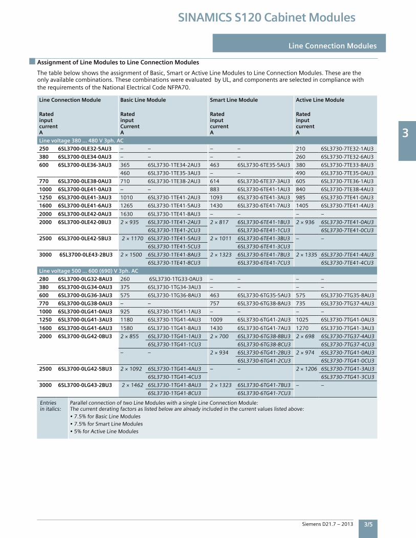
Assignment of Line Modules to Line Connection Modules
Line Connection Modules
ThetablebelowshowstheassignmentofBasic,SmartorActiveLineModulestoLineConnectionModules.Thesearetheonlyavailablecombinations.ThesecombinationswereevaluatedbyUL,andcomponentsareselectedincompliancewiththerequirementsoftheNationalElectricalCodeNFPA70.
Line Connection Module Basic Line Module Smart Line Module Active Line Module
RatedinputcurrentA
RatedinputCurrentA
RatedinputcurrentA
RatedinputcurrentA
Line voltage 380 … 480 V 3ph. AC
250 6SL3700-0LE32-5AU3 – – – – 210 6SL3730-7TE32-1AU3
380 6SL3700-0LE34-0AU3 – – – – 260 6SL3730-7TE32-6AU3
600 6SL3700-0LE36-3AU3 365 6SL3730-1TE34-2AU3 463 6SL3730-6TE35-5AU3 380 6SL3730-7TE33-8AU3
460 6SL3730-1TE35-3AU3 – – 490 6SL3730-7TE35-0AU3
770 6SL3700-0LE38-0AU3 710 6SL3730-1TE38-2AU3 614 6SL3730-6TE37-3AU3 605 6SL3730-7TE36-1AU3
1000 6SL3700-0LE41-0AU3 – – 883 6SL3730-6TE41-1AU3 840 6SL3730-7TE38-4AU3
1250 6SL3700-0LE41-3AU3 1010 6SL3730-1TE41-2AU3 1093 6SL3730-6TE41-3AU3 985 6SL3730-7TE41-0AU3
1600 6SL3700-0LE41-6AU3 1265 6SL3730-1TE41-5AU3 1430 6SL3730-6TE41-7AU3 1405 6SL3730-7TE41-4AU3
2000 6SL3700-0LE42-0AU3 1630 6SL3730-1TE41-8AU3 – – – –
2000 6SL3700-0LE42-0BU3 2×935 6SL3730-1TE41-2AU3 2×817 6SL3730-6TE41-1BU3 2×936 6SL3730-7TE41-0AU3
6SL3730-1TE41-2CU3 6SL3730-6TE41-1CU3 6SL3730-7TE41-0CU3
2500 6SL3700-0LE42-5BU3 2×1170 6SL3730-1TE41-5AU3 2×10¹¹ 6SL3730-6TE41-3BU3 – –
6SL3730-1TE41-5CU3 6SL3730-6TE41-3CU3
3000 6SL3700-0LE43-2BU3 2×1500 6SL3730-1TE41-8AU3 2×1323 6SL3730-6TE41-7BU3 2×1335 6SL3730-7TE41-4AU3
6SL3730-1TE41-8CU3 6SL3730-6TE41-7CU3 6SL3730-7TE41-4CU3
Line voltage 500 … 600 (690) V 3ph. AC
280 6SL3700-0LG32-8AU3 260 6SL3730-1TG33-0AU3 – – – –
380 6SL3700-0LG34-0AU3 375 6SL3730-1TG34-3AU3 – – – –
600 6SL3700-0LG36-3AU3 575 6SL3730-1TG36-8AU3 463 6SL3730-6TG35-5AU3 575 6SL3730-7TG35-8AU3
770 6SL3700-0LG38-0AU3 – – 757 6SL3730-6TG38-8AU3 735 6SL3730-7TG37-4AU3
1000 6SL3700-0LG41-0AU3 925 6SL3730-1TG41-1AU3 – – – –
1250 6SL3700-0LG41-3AU3 1180 6SL3730-1TG41-4AU3 1009 6SL3730-6TG41-2AU3 1025 6SL3730-7TG41-0AU3
1600 6SL3700-0LG41-6AU3 1580 6SL3730-1TG41-8AU3 1430 6SL3730-6TG41-7AU3 1270 6SL3730-7TG41-3AU3
2000 6SL3700-0LG42-0BU3 2×855 6SL3730-1TG41-1AU3 2×700 6SL3730-6TG38-8BU3 2×698 6SL3730-7TG37-4AU3
6SL3730-1TG41-1CU3 6SL3730-6TG38-8CU3 6SL3730-7TG37-4CU3
– – 2×934 6SL3730-6TG41-2BU3 2×974 6SL3730-7TG41-0AU3
6SL3730-6TG41-2CU3 6SL3730-7TG41-0CU3
2500 6SL3700-0LG42-5BU3 2×1092 6SL3730-1TG41-4AU3 – – 2×1206 6SL3730-7TG41-3AU3
6SL3730-1TG41-4CU3 6SL3730-7TG41-3CU3
3000 6SL3700-0LG43-2BU3 2×1462 6SL3730-1TG41-8AU3 2×1323 6SL3730-6TG41-7BU3 – –
6SL3730-1TG41-8CU3 6SL3730-6TG41-7CU3
Entries ParallelconnectionoftwoLineModuleswithasingleLineConnectionModule:initalics: Thecurrentderatingfactorsaslistedbelowarealreadyincludedinthecurrentvalueslistedabove: •7.5%forBasicLineModules •7.5%forSmartLineModules •5%forActiveLineModules
3
3/6 Siemens D21.7 – 2013
SINAMICS S120 Cabinet Modules
Line Connection Modules
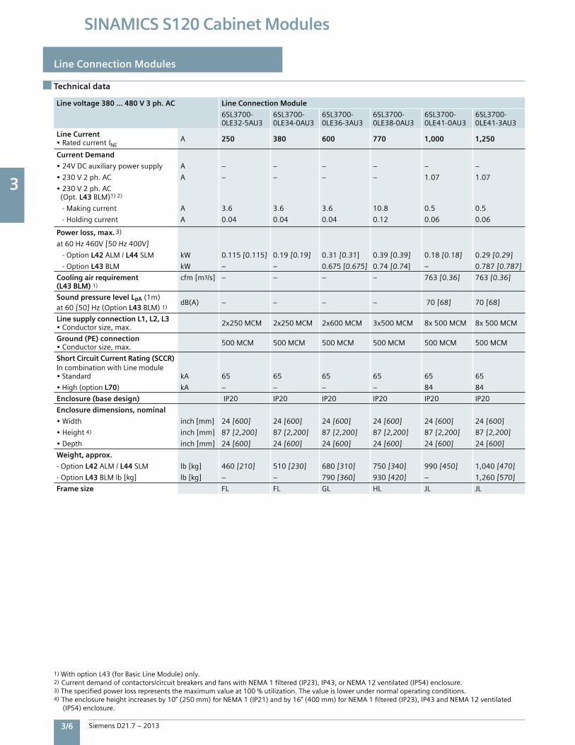
Line voltage 380 … 480 V 3 ph. AC Line Connection Module
6SL3700-0LE32-5AU3
6SL3700-0LE34-0AU3
6SL3700-0LE36-3AU3
6SL3700-0LE38-0AU3
6SL3700-0LE41-0AU3
6SL3700-0LE41-3AU3
Line Current•RatedcurrentINE
A 250 380 600 770 1,000 1,250
Current Demand
•24VDCauxiliarypowersupply A – – – – – –
•230V2ph.AC A – – – – 1.07 1.07
•230V2ph.AC(Opt.L43BLM)1)2)
-Makingcurrent A 3.6 3.6 3.6 10.8 0.5 0.5
-Holdingcurrent A 0.04 0.04 0.04 0.12 0.06 0.06
Power loss, max.3)
at60Hz460V[50Hz400V]
-OptionL42ALM/L44SLM kW 0.115[0.115] 0.19[0.19] 0.31[0.31] 0.39[0.39] 0.18[0.18] 0.29[0.29]
-OptionL43BLM kW – – 0.675[0.675] 0.74[0.74] – 0.787[0.787]
Cooling air requirement (L43 BLM) 1)
cfm[m3/s] – – – – 763[0.36] 763[0.36]
Sound pressure level LpA(1m)at60[50]Hz(OptionL43BLM)1)
dB(A) – – – – 70[68] 70[68]
Line supply connection L1, L2, L3•Conductorsize,max. 2x250MCM 2x250MCM 2x600MCM 3x500MCM 8x500MCM 8x500MCM
Ground (PE) connection •Conductorsize,max. 500MCM 500MCM 500MCM 500MCM 500MCM 500MCM
Short Circuit Current Rating (SCCR)IncombinationwithLinemodule•Standard kA 65 65 65 65 65 65
•High(option L70) kA – – – – 84 84
Enclosure (base design) IP20 IP20 IP20 IP20 IP20 IP20
Enclosure dimensions, nominal
•Width inch[mm] 24[600] 24[600] 24[600] 24[600] 24[600] 24[600]
•Height4) inch[mm] 87[2,200] 87[2,200] 87[2,200] 87[2,200] 87[2,200] 87[2,200]
•Depth inch[mm] 24[600] 24[600] 24[600] 24[600] 24[600] 24[600]
Weight, approx.
-OptionL42ALM/L44SLM lb[kg] 460[210] 510[230] 680[310] 750[340] 990[450] 1,040[470]
-OptionL43BLMlb[kg] lb[kg] – – 790[360] 930[420] – 1,260[570]
Frame size FL FL GL HL JL JL
Technical data
1)WithoptionL43(forBasicLineModule)only.2)Currentdemandofcontactors/circuitbreakersandfanswithNEMA1filtered(IP23),IP43,orNEMA12ventilated(IP54)enclosure.3)Thespecifiedpowerlossrepresentsthemaximumvalueat100%utilization.Thevalueislowerundernormaloperatingconditions.4)Theenclosureheightincreasesby10”(250mm)forNEMA1(IP21)andby16”(400mm)forNEMA1filtered(IP23),IP43andNEMA12ventilated(IP54)enclosure.
3
Siemens D21.7 – 2013 3/7
SINAMICS S120 Cabinet Modules
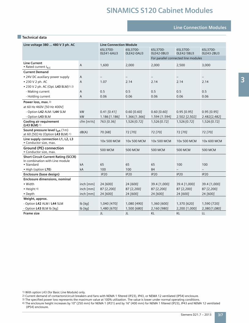
Line voltage 380 … 480 V 3 ph. AC Line Connection Module
6SL3700-0LE41-6AU3
6SL3700-0LE42-0AU3
6SL3700-0LE42-0BU3
6SL3700-0LE42-5BU3
6SL3700-0LE43-2BU3
Forparallelconnectedlinemodules
Line Current•RatedcurrentINE
A 1,600 2,000 2,000 2,500 3,000
Current Demand
•24VDCauxiliarypowersupply A – – – – –
•230V2ph.AC A 1.07 2.14 2.14 2.14 2.14
•230V2ph.AC(Opt.L43BLM)1)2)
-Makingcurrent A 0.5 0.5 0.5 0.5 0.5
-Holdingcurrent A 0.06 0.06 0.06 0.06 0.06
Power loss, max.3)
at60Hz460V[50Hz400V]
-OptionL42ALM/L44SLM kW 0.41[0.41] 0.60[0.60] 0.60[0.60] 0.95[0.95] 0.95[0.95]
-OptionL43BLM kW 1.186 [1.186] 1.366 [1.366] 1.594[1.594] 2.502[2,502] 2.482[2,482]
Cooling air requirement (L43 BLM) 1)
cfm[m3/s] 763[0.36] 1,526 [0.72] 1,526 [0.72] 1,526 [0.72] 1,526 [0.72]
Sound pressure level LpA(1m)at60[50]Hz(OptionL43BLM)1)
dB(A) 70[68] 72[70] 72[70] 72[70] 72[70]
Line supply connection L1, L2, L3•Conductorsize,max. 10x500MCM 10x500MCM 10x500MCM 10x500MCM 10x600MCM
Ground (PE) connection •Conductorsize,max.
500MCM 500MCM 500MCM 500MCM 500MCM
Short Circuit Current Rating (SCCR)IncombinationwithLinemodule•Standard kA 65 65 65 100 100
•High(optionL70) kA 100 100 84 – –
Enclosure (base design) IP20 IP20 IP20 IP20 IP20
Enclosure dimensions, nominal
•Width inch[mm] 24[600] 24[600] 39.4[1,000] 39.4[1,000] 39.4[1,000]
•Height4) inch[mm] 87[2,200] 87[2,200] 87[2,200] 87[2,200] 87[2,200]
•Depth inch[mm] 24[600] 24[600] 24[600] 24[600] 24[600]
Weight, approx.
-OptionL42ALM/L44SLM lb[kg] 1,040[470] 1,080[490] 1,360[600] 1,370[620] 1,590[720]
-OptionL43BLMlb[kg] lb[kg] 1,480[670] 1,500[680] 2,160[980] 2,200[1,000] 2,380[1,080]
Frame size JL JL KL KL LL
Line voltage 380 … 480 V 3 ph. AC Line Connection Module
6SL3700-0LE32-5AU3
6SL3700-0LE34-0AU3
6SL3700-0LE36-3AU3
6SL3700-0LE38-0AU3
6SL3700-0LE41-0AU3
6SL3700-0LE41-3AU3
Line Current•RatedcurrentINE
A 250 380 600 770 1,000 1,250
Current Demand
•24VDCauxiliarypowersupply A – – – – – –
•230V2ph.AC A – – – – 1.07 1.07
•230V2ph.AC(Opt.L43BLM)1)2)
-Makingcurrent A 3.6 3.6 3.6 10.8 0.5 0.5
-Holdingcurrent A 0.04 0.04 0.04 0.12 0.06 0.06
Power loss, max.3)
at60Hz460V[50Hz400V]
-OptionL42ALM/L44SLM kW 0.115[0.115] 0.19[0.19] 0.31[0.31] 0.39[0.39] 0.18[0.18] 0.29[0.29]
-OptionL43BLM kW – – 0.675[0.675] 0.74[0.74] – 0.787[0.787]
Cooling air requirement (L43 BLM) 1)
cfm[m3/s] – – – – 763[0.36] 763[0.36]
Sound pressure level LpA(1m)at60[50]Hz(OptionL43BLM)1)
dB(A) – – – – 70[68] 70[68]
Line supply connection L1, L2, L3•Conductorsize,max. 2x250MCM 2x250MCM 2x600MCM 3x500MCM 8x500MCM 8x500MCM
Ground (PE) connection •Conductorsize,max. 500MCM 500MCM 500MCM 500MCM 500MCM 500MCM
Short Circuit Current Rating (SCCR)IncombinationwithLinemodule•Standard kA 65 65 65 65 65 65
•High(option L70) kA – – – – 84 84
Enclosure (base design) IP20 IP20 IP20 IP20 IP20 IP20
Enclosure dimensions, nominal
•Width inch[mm] 24[600] 24[600] 24[600] 24[600] 24[600] 24[600]
•Height4) inch[mm] 87[2,200] 87[2,200] 87[2,200] 87[2,200] 87[2,200] 87[2,200]
•Depth inch[mm] 24[600] 24[600] 24[600] 24[600] 24[600] 24[600]
Weight, approx.
-OptionL42ALM/L44SLM lb[kg] 460[210] 510[230] 680[310] 750[340] 990[450] 1,040[470]
-OptionL43BLMlb[kg] lb[kg] – – 790[360] 930[420] – 1,260[570]
Frame size FL FL GL HL JL JL
Technical data
Line Connection Modules
1)WithoptionL43(forBasicLineModule)only.2)Currentdemandofcontactors/circuitbreakersandfanswithNEMA1filtered(IP23),IP43,orNEMA12ventilated(IP54)enclosure.3)Thespecifiedpowerlossrepresentsthemaximumvalueat100%utilization.Thevalueislowerundernormaloperatingconditions.4)Theenclosureheightincreasesby10”(250mm)forNEMA1(IP21)andby16”(400mm)forNEMA1filtered(IP23),IP43andNEMA12ventilated(IP54)enclosure.
3
3/8 Siemens D21.7 – 2013
SINAMICS S120 Cabinet Modules
Line Connection Modules
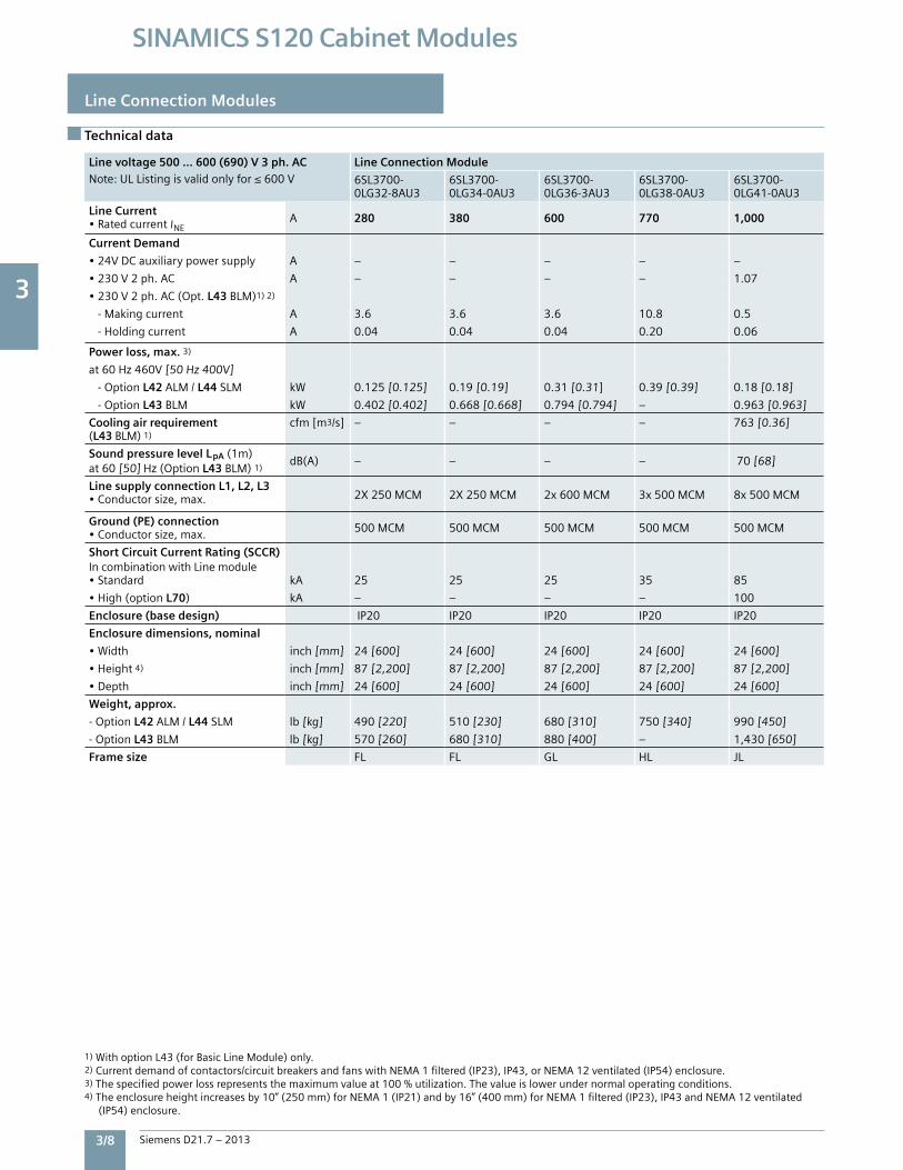
Line voltage 500 … 600 (690) V 3 ph. ACNote:ULListingisvalidonlyfor≤600V
Line Connection Module
6SL3700-0LG32-8AU3
6SL3700-0LG34-0AU3
6SL3700-0LG36-3AU3
6SL3700-0LG38-0AU3
6SL3700-0LG41-0AU3
Line Current•RatedcurrentINE A 280 380 600 770 1,000
Current Demand
•24VDCauxiliarypowersupply A – – – – –
•230V2ph.AC A – – – – 1.07
•230V2ph.AC(Opt.L43BLM)1)2)
-Makingcurrent A 3.6 3.6 3.6 10.8 0.5
-Holdingcurrent A 0.04 0.04 0.04 0.20 0.06
Power loss, max. 3)
at60Hz460V[50Hz400V]
-OptionL42ALM/L44SLM kW 0.125[0.125] 0.19[0.19] 0.31[0.31] 0.39[0.39] 0.18[0.18]
-OptionL43BLM kW 0.402[0.402] 0.668[0.668] 0.794[0.794] – 0.963[0.963]
Cooling air requirement (L43 BLM) 1)
cfm[m3/s] – – – – 763[0.36]
Sound pressure level LpA(1m)at60[50]Hz(OptionL43BLM)1)
dB(A) – – – – 70[68]
Line supply connection L1, L2, L3•Conductorsize,max. 2X250MCM 2X250MCM 2x600MCM 3x500MCM 8x500MCM
Ground (PE) connection •Conductorsize,max. 500MCM 500MCM 500MCM 500MCM 500MCM
Short Circuit Current Rating (SCCR)IncombinationwithLinemodule•Standard kA 25 25 25 35 85
•High(optionL70) kA – – – – 100
Enclosure (base design) IP20 IP20 IP20 IP20 IP20
Enclosure dimensions, nominal
•Width inch[mm] 24[600] 24[600] 24[600] 24[600] 24[600]
•Height4) inch[mm] 87[2,200] 87[2,200] 87[2,200] 87[2,200] 87[2,200]
•Depth inch[mm] 24[600] 24[600] 24[600] 24[600] 24[600]
Weight, approx.
-OptionL42ALM/L44SLM lb[kg] 490[220] 510[230] 680[310] 750[340] 990[450]
-OptionL43BLM lb[kg] 570[260] 680[310] 880[400] – 1,430[650]
Frame size FL FL GL HL JL
Technical data
1)WithoptionL43(forBasicLineModule)only.2)Currentdemandofcontactors/circuitbreakersandfanswithNEMA1filtered(IP23),IP43,orNEMA12ventilated(IP54)enclosure.3)Thespecifiedpowerlossrepresentsthemaximumvalueat100%utilization.Thevalueislowerundernormaloperatingconditions.4)Theenclosureheightincreasesby10”(250mm)forNEMA1(IP21)andby16”(400mm)forNEMA1filtered(IP23),IP43andNEMA12ventilated(IP54)enclosure.
3
Siemens D21.7 – 2013 3/9
SINAMICS S120 Cabinet Modules
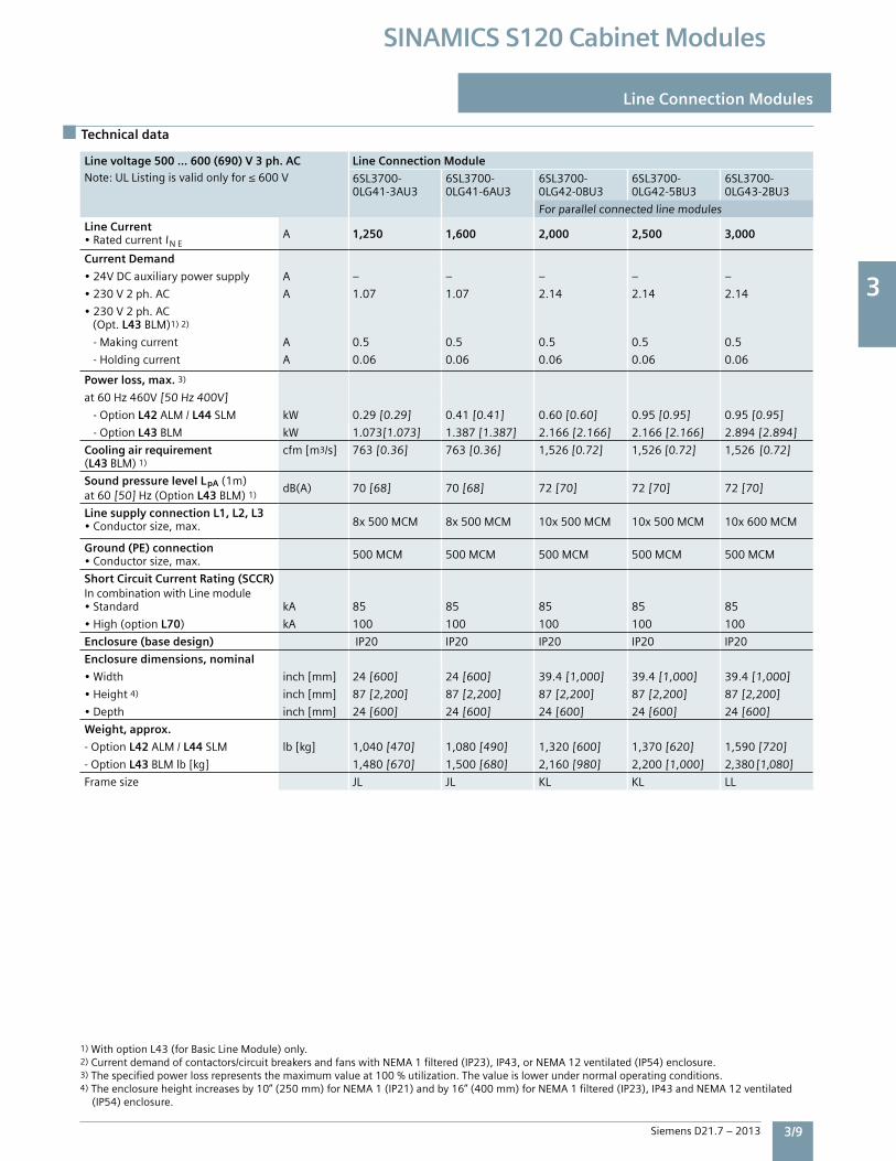
Line voltage 500 … 600 (690) V 3 ph. ACNote:ULListingisvalidonlyfor≤600V
Line Connection Module
6SL3700-0LG32-8AU3
6SL3700-0LG34-0AU3
6SL3700-0LG36-3AU3
6SL3700-0LG38-0AU3
6SL3700-0LG41-0AU3
Line Current•RatedcurrentINE A 280 380 600 770 1,000
Current Demand
•24VDCauxiliarypowersupply A – – – – –
•230V2ph.AC A – – – – 1.07
•230V2ph.AC(Opt.L43BLM)1)2)
-Makingcurrent A 3.6 3.6 3.6 10.8 0.5
-Holdingcurrent A 0.04 0.04 0.04 0.20 0.06
Power loss, max. 3)
at60Hz460V[50Hz400V]
-OptionL42ALM/L44SLM kW 0.125[0.125] 0.19[0.19] 0.31[0.31] 0.39[0.39] 0.18[0.18]
-OptionL43BLM kW 0.402[0.402] 0.668[0.668] 0.794[0.794] – 0.963[0.963]
Cooling air requirement (L43 BLM) 1)
cfm[m3/s] – – – – 763[0.36]
Sound pressure level LpA(1m)at60[50]Hz(OptionL43BLM)1)
dB(A) – – – – 70[68]
Line supply connection L1, L2, L3•Conductorsize,max. 2X250MCM 2X250MCM 2x600MCM 3x500MCM 8x500MCM
Ground (PE) connection •Conductorsize,max. 500MCM 500MCM 500MCM 500MCM 500MCM
Short Circuit Current Rating (SCCR)IncombinationwithLinemodule•Standard kA 25 25 25 35 85
•High(optionL70) kA – – – – 100
Enclosure (base design) IP20 IP20 IP20 IP20 IP20
Enclosure dimensions, nominal
•Width inch[mm] 24[600] 24[600] 24[600] 24[600] 24[600]
•Height4) inch[mm] 87[2,200] 87[2,200] 87[2,200] 87[2,200] 87[2,200]
•Depth inch[mm] 24[600] 24[600] 24[600] 24[600] 24[600]
Weight, approx.
-OptionL42ALM/L44SLM lb[kg] 490[220] 510[230] 680[310] 750[340] 990[450]
-OptionL43BLM lb[kg] 570[260] 680[310] 880[400] – 1,430[650]
Frame size FL FL GL HL JL
Technical data
Line Connection Modules
1)WithoptionL43(forBasicLineModule)only.2)Currentdemandofcontactors/circuitbreakersandfanswithNEMA1filtered(IP23),IP43,orNEMA12ventilated(IP54)enclosure.3)Thespecifiedpowerlossrepresentsthemaximumvalueat100%utilization.Thevalueislowerundernormaloperatingconditions.4)Theenclosureheightincreasesby10”(250mm)forNEMA1(IP21)andby16”(400mm)forNEMA1filtered(IP23),IP43andNEMA12ventilated(IP54)enclosure.
Line voltage 500 … 600 (690) V 3 ph. ACNote:ULListingisvalidonlyfor≤600V
Line Connection Module
6SL3700-0LG41-3AU3
6SL3700-0LG41-6AU3
6SL3700-0LG42-0BU3
6SL3700-0LG42-5BU3
6SL3700-0LG43-2BU3
Forparallelconnectedlinemodules
Line Current•RatedcurrentINE
A 1,250 1,600 2,000 2,500 3,000
Current Demand
•24VDCauxiliarypowersupply A – – – – –
•230V2ph.AC A 1.07 1.07 2.14 2.14 2.14
•230V2ph.AC(Opt.L43BLM)1)2)
-Makingcurrent A 0.5 0.5 0.5 0.5 0.5
-Holdingcurrent A 0.06 0.06 0.06 0.06 0.06
Power loss, max. 3)
at60Hz460V[50Hz400V]
-OptionL42ALM/L44SLM kW 0.29[0.29] 0.41[0.41] 0.60[0.60] 0.95[0.95] 0.95[0.95]
-OptionL43BLM kW 1.073[1.073] 1.387[1.387] 2.166[2.166] 2.166[2.166] 2.894[2.894]
Cooling air requirement (L43 BLM) 1)
cfm[m3/s] 763[0.36] 763[0.36] 1,526[0.72] 1,526[0.72] 1,526 [0.72]
Sound pressure level LpA(1m)at60[50]Hz(OptionL43BLM)1)
dB(A) 70[68] 70[68] 72[70] 72[70] 72[70]
Line supply connection L1, L2, L3•Conductorsize,max. 8x500MCM 8x500MCM 10x500MCM 10x500MCM 10x600MCM
Ground (PE) connection •Conductorsize,max. 500MCM 500MCM 500MCM 500MCM 500MCM
Short Circuit Current Rating (SCCR)IncombinationwithLinemodule•Standard kA 85 85 85 85 85
•High(optionL70) kA 100 100 100 100 100
Enclosure (base design) IP20 IP20 IP20 IP20 IP20
Enclosure dimensions, nominal
•Width inch[mm] 24[600] 24[600] 39.4[1,000] 39.4[1,000] 39.4[1,000]
•Height4) inch[mm] 87[2,200] 87[2,200] 87[2,200] 87[2,200] 87[2,200]
•Depth inch[mm] 24[600] 24[600] 24[600] 24[600] 24[600]
Weight, approx.
-OptionL42ALM/L44SLM lb[kg] 1,040[470] 1,080[490] 1,320[600] 1,370[620] 1,590[720]
-OptionL43BLMlb[kg] 1,480[670] 1,500[680] 2,160[980] 2,200[1,000] 2,380[1,080]
Framesize JL JL KL KL LL
3
3/10 Siemens D21.7 – 2013
SINAMICS S120 Cabinet Modules
Line Connection Modules
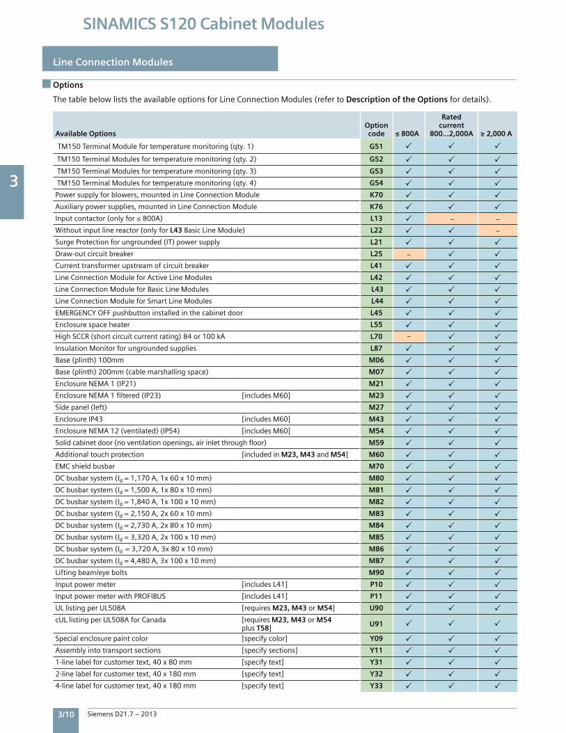
Options
ThetablebelowliststheavailableoptionsforLineConnectionModules(refertoDescription of the Optionsfordetails).
Available Options Option code ≤ 800A
Rated current
800…2,000A ≥ 2,000 A
TM150TerminalModulefortemperaturemonitoring(qty.1) G51
TM150TerminalModulesfortemperaturemonitoring(qty.2) G52
TM150TerminalModulesfortemperaturemonitoring(qty.3) G53
TM150TerminalModulesfortemperaturemonitoring(qty.4) G54
Powersupplyforblowers,mountedinLineConnectionModule K70
Auxiliarypowersupplies,mountedinLineConnectionModule K76
Inputcontactor(onlyfor≤800A) L13 – –
Withoutinputlinereactor(onlyforL43BasicLineModule) L22 –
SurgeProtectionforungrounded(IT)powersupply L21
Draw-outcircuitbreaker L25 –
Currenttransformerupstreamofcircuitbreaker L41
LineConnectionModuleforActiveLineModules L42
LineConnectionModuleforBasicLineModules L43
LineConnectionModuleforSmartLineModules L44
EMERGENCYOFFpushbuttoninstalledinthecabinetdoor L45
Enclosurespaceheater L55
HighSCCR(shortcircuitcurrentrating)84or100kA L70 –
InsulationMonitorforungroundedsupplies L87
Base(plinth)100mm M06
Base(plinth)200mm(cablemarshallingspace) M07
EnclosureNEMA1(IP21) M21
EnclosureNEMA1filtered(IP23) [includesM60] M23
Sidepanel(left) M27
EnclosureIP43 [includesM60] M43
EnclosureNEMA12(ventilated)(IP54) [includesM60] M54
Solidcabinetdoor(noventilationopenings,airinletthroughfloor) M59
Additionaltouchprotection [includedinM23, M43andM54] M60
EMCshieldbusbar M70
DCbusbarsystem(Id=1,170A,1x60x10mm) M80
DCbusbarsystem(Id=1,500A,1x80x10mm) M81
DCbusbarsystem(Id=1,840A,1x100x10mm) M82
DCbusbarsystem(Id=2,150A,2x60x10mm) M83
DCbusbarsystem(Id=2,730A,2x80x10mm) M84
DCbusbarsystem(Id=3,320A,2x100x10mm) M85
DCbusbarsystem(Id=3,720A,3x80x10mm) M86
DCbusbarsystem(Id=4,480A,3x100x10mm) M87
Liftingbeam/eyebolts M90
Inputpowermeter [includesL41] P10
InputpowermeterwithPROFIBUS [includesL41] P11
ULlistingperUL508A [requiresM23, M43 or M54] U90
cULlistingperUL508AforCanada [requiresM23, M43 or M54plusT58] U91
Specialenclosurepaintcolor [specifycolor] Y09
Assemblyintotransportsections [specifysections] Y11
1-linelabelforcustomertext,40x80mm [specifytext] Y31
2-linelabelforcustomertext,40x180mm [specifytext] Y32
4-linelabelforcustomertext,40x180mm [specifytext] Y33
3
Siemens D21.7 – 2013 3/11
SINAMICS S120 Cabinet Modules
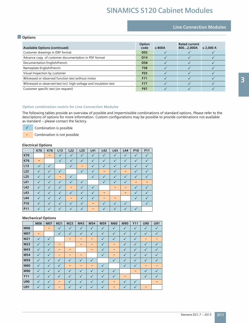
Options
Line Connection Modules
Available Options (continued)Option code ≤ 800A
Rated current800…2,000A ≥ 2,000 A
CustomerdrawingsinDXFformat D02
AdvancecopyofcustomerdocumentationinPDFformat D14
DocumentationEnglish/French D58
NameplateEnglish/French T58
VisualInspectionbycustomer F03
Witnessedorobservedfunctiontestwithoutmotor F71
Witnessedorobservedtestincl.high-voltageandinsulationtest F77
Customerspecifictest(onrequest) F97
Option combination matrix for Line Connection Modules
Thefollowingtablesprovideanoverviewofpossibleandimpermissiblecombinationsofstandardoptions.Pleaserefertothedescriptionsofoptionsformoreinformation.Customconfigurationsmaybepossibletoprovidecombinationsnotavailableasstandard–pleasecontactthefactory.
Combinationispossible
–Combinationisnotpossible
Electrical Options
K70 K76 L13 L22 L25 L41 L42 L43 L44 P10 P11
K70 –
K76 –
L13 –
L22 – –
L25 –
L41 – –
L42 – – –
L43 – –
L44 – – –
P10 –
P11 –
Mechanical Options
M06 M07 M21 M23 M43 M54 M59 M60 M90 Y11 U90 U91
M06 –
M07 –
M21 – – – – –
M23 – – – –
M43 – – – –
M54 – – – –
M59
M60 – – – – –
M90 –
Y11 –
U90 – – –
U91 – – –
3
3/12 Siemens D21.7 – 2013
SINAMICS S120 Cabinet Modules
Line Connection Modules
Options
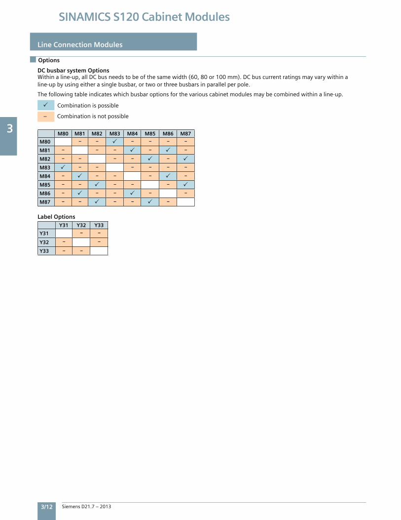
DC busbar system OptionsWithinaline-up,allDCbusneedstobeofthesamewidth(60,80or100mm).DCbuscurrentratingsmayvarywithinaline-upbyusingeitherasinglebusbar,ortwoorthreebusbarsinparallelperpole.
Thefollowingtableindicateswhichbusbaroptionsforthevariouscabinetmodulesmaybecombinedwithinaline-up.
Combinationispossible
–Combinationisnotpossible
M80 M81 M82 M83 M84 M85 M86 M87
M80 – – – – – –
M81 – – – – –
M82 – – – – –
M83 – – – – – –
M84 – – – – –
M85 – – – – –
M86 – – – – –
M87 – – – – –
Y31 Y32 Y33
Y31 – –
Y32 – –
Y33 – –
Label Options
3
Siemens D21.7 – 2013 3/13
SINAMICS S120 Cabinet Modules
Basic Line Modules
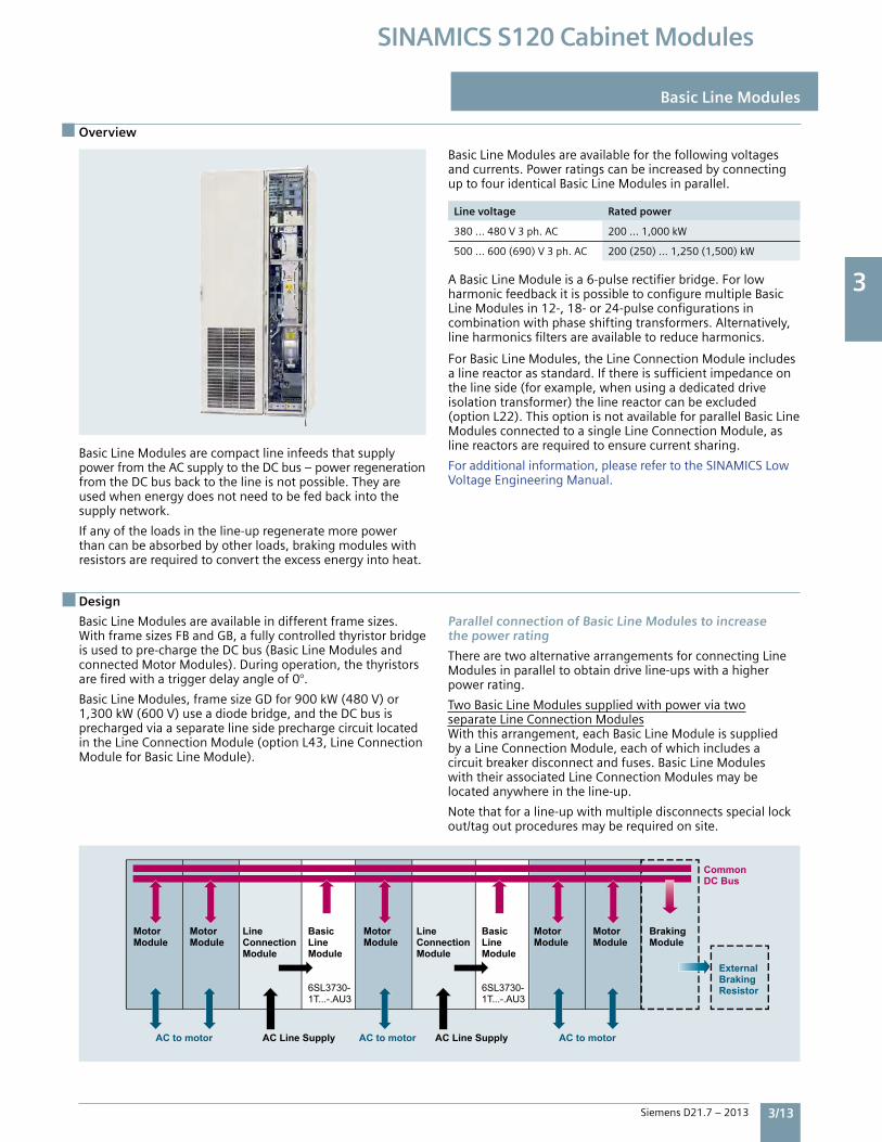
BasicLineModulesarecompactlineinfeedsthatsupplypowerfromtheACsupplytotheDCbus–powerregenerationfromtheDCbusbacktothelineisnotpossible.Theyareusedwhenenergydoesnotneedtobefedbackintothesupplynetwork.
Ifanyoftheloadsintheline-upregeneratemorepowerthancanbeabsorbedbyotherloads,brakingmoduleswithresistorsarerequiredtoconverttheexcessenergyintoheat.
BasicLineModulesareavailableforthefollowingvoltagesandcurrents.PowerratingscanbeincreasedbyconnectinguptofouridenticalBasicLineModulesinparallel.
Line voltage Rated power
380…480V3ph.AC 200…1,000kW
500…600(690)V3ph.AC 200(250)…1,250(1,500)kW
ABasicLineModuleisa6-pulserectifierbridge.ForlowharmonicfeedbackitispossibletoconfiguremultipleBasicLineModulesin12-,18-or24-pulseconfigurationsincombinationwithphaseshiftingtransformers.Alternatively,lineharmonicsfiltersareavailabletoreduceharmonics.
ForBasicLineModules,theLineConnectionModuleincludesalinereactorasstandard.Ifthereissufficientimpedanceonthelineside(forexample,whenusingadedicateddriveisolationtransformer)thelinereactorcanbeexcluded(optionL22).ThisoptionisnotavailableforparallelBasicLineModulesconnectedtoasingleLineConnectionModule,aslinereactorsarerequiredtoensurecurrentsharing.
Foradditionalinformation,pleaserefertotheSINAMICSLowVoltageEngineeringManual.
Overview
BasicLineModulesareavailableindifferentframesizes.WithframesizesFBandGB,afullycontrolledthyristorbridgeisusedtopre-chargetheDCbus(BasicLineModulesandconnectedMotorModules).Duringoperation,thethyristorsarefiredwithatriggerdelayangleof0°.
BasicLineModules,framesizeGDfor900kW(480V)or1,300kW(600V)useadiodebridge,andtheDCbusisprechargedviaaseparatelinesideprechargecircuitlocatedintheLineConnectionModule(optionL43,LineConnectionModuleforBasicLineModule).
Parallel connection of Basic Line Modules to increasethe power rating
TherearetwoalternativearrangementsforconnectingLineModulesinparalleltoobtaindriveline-upswithahigherpowerrating.
TwoBasicLineModulessuppliedwithpowerviatwoseparateLineConnectionModulesWiththisarrangement,eachBasicLineModuleissuppliedbyaLineConnectionModule,eachofwhichincludesacircuitbreakerdisconnectandfuses.BasicLineModuleswiththeirassociatedLineConnectionModulesmaybelocatedanywhereintheline-up.
Notethatforaline-upwithmultipledisconnectsspeciallockout/tagoutproceduresmayberequiredonsite.
Design
LineConnectionModule
BasicLineModule
BasicLineModule
LineConnectionModule
Motor Module
Motor Module
Motor Module
Motor Module
Motor Module
Braking Module
Common DC Bus
ExternalBraking Resistor
AC to motorAC to motor AC to motor AC Line SupplyAC Line Supply
6SL3730-1T...-.AU3
6SL3730-1T...-.AU3
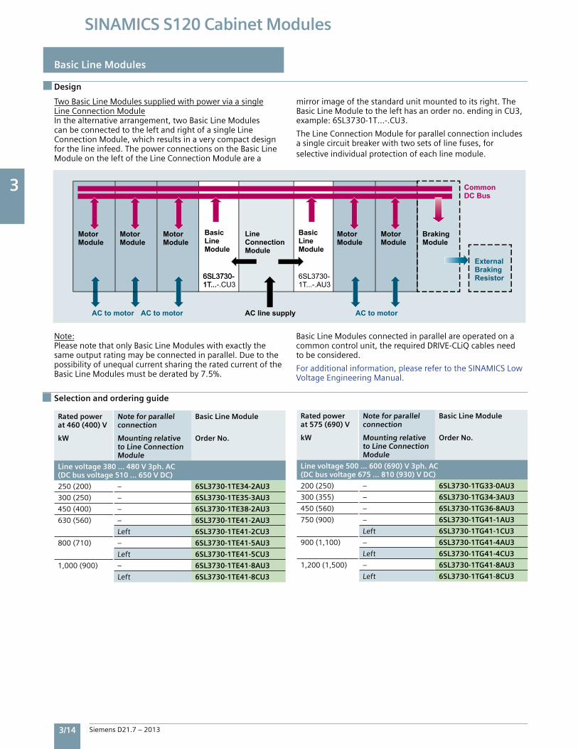
3
3/14 Siemens D21.7 – 2013
SINAMICS S120 Cabinet Modules
Basic Line Modules
Design
TwoBasicLineModulessuppliedwithpowerviaasingleLineConnectionModuleInthealternativearrangement,twoBasicLineModulescanbeconnectedtotheleftandrightofasingleLineConnectionModule,whichresultsinaverycompactdesignforthelineinfeed.ThepowerconnectionsontheBasicLineModuleontheleftoftheLineConnectionModulearea
mirrorimageofthestandardunitmountedtoitsright.TheBasicLineModuletothelefthasanorderno.endinginCU3,example:6SL3730-1T…-.CU3.
TheLineConnectionModuleforparallelconnectionincludesasinglecircuitbreakerwithtwosetsoflinefuses,forselectiveindividualprotectionofeachlinemodule.
Note:PleasenotethatonlyBasicLineModuleswithexactlythesameoutputratingmaybeconnectedinparallel.DuetothepossibilityofunequalcurrentsharingtheratedcurrentoftheBasicLineModulesmustbederatedby7.5%.
BasicLineModulesconnectedinparallelareoperatedonacommoncontrolunit,therequiredDRIVE-CLiQcablesneedtobeconsidered.
Foradditionalinformation,pleaserefertotheSINAMICSLowVoltageEngineeringManual.
Rated power at 460 (400) V
kW
Note for parallelconnection
Mounting relativeto Line ConnectionModule
Basic Line Module
Order No.
Line voltage 380 … 480 V 3ph. AC(DC bus voltage 510 … 650 V DC)
250(200) – 6SL3730-1TE34-2AU3
300(250) – 6SL3730-1TE35-3AU3
450(400) – 6SL3730-1TE38-2AU3
630(560) – 6SL3730-1TE41-2AU3
Left 6SL3730-1TE41-2CU3
800(710) – 6SL3730-1TE41-5AU3
Left 6SL3730-1TE41-5CU3
1,000(900) – 6SL3730-1TE41-8AU3
Left 6SL3730-1TE41-8CU3
Rated power at 575 (690) V
kW
Note for parallelconnection
Mounting relativeto Line ConnectionModule
Basic Line Module
Order No.
Line voltage 500 … 600 (690) V 3ph. AC(DC bus voltage 675 … 810 (930) V DC)
200(250) – 6SL3730-1TG33-0AU3
300(355) – 6SL3730-1TG34-3AU3
450(560) – 6SL3730-1TG36-8AU3
750(900) – 6SL3730-1TG41-1AU3
Left 6SL3730-1TG41-1CU3
900(1,100) – 6SL3730-1TG41-4AU3
Left 6SL3730-1TG41-4CU3
1,200(1,500) – 6SL3730-1TG41-8AU3
Left 6SL3730-1TG41-8CU3
Selection and ordering guide
Motor Module
Motor Module
Motor Module
Motor Module
Motor Module
Braking Module
Common DC Bus
ExternalBraking Resistor
LineConnectionModule
6SL3730-1T...-.CU36SL3730-1T...
6SL3730-1T...-.AU3
AC to motor AC to motor AC line supply AC to motor
BasicLineModule
BasicLineModule
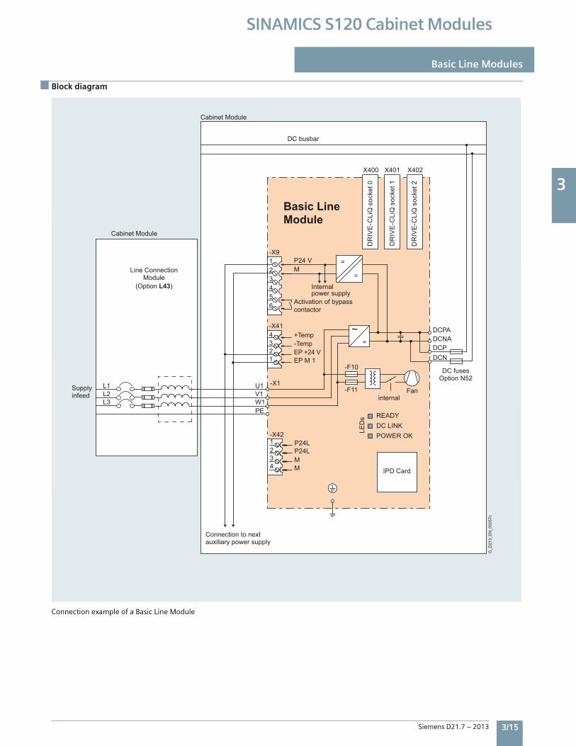
3
Siemens D21.7 – 2013 3/15
SINAMICS S120 Cabinet Modules
Block diagram
Basic Line Modules
ConnectionexampleofaBasicLineModule
Line Connection Module
(Option L43)
Cabinet Module
DR
IVE
-CLi
Q s
ocke
t 0
DR
IVE
-CLi
Q s
ocke
t 1
DR
IVE
-CLi
Q s
ocke
t 2
Activation of bypass contactor
DC fusesOption N52
DC busbar
G_D
213_
EN
_000
57c
Internalpower supply
internalFanSupply
infeed
Connection to next auxiliary power supply
Cabinet Module
EP +24 V
P24 V
P24L P24L
4321-X42
MM
L3L2L1
IPD Card
Basic Line Module
DCNADCPA
DCNDCP
~=
=
=
-F11
-F10
X402X401X400
1234-X41
EP M 1
-X9
654321
M
PEW1V1
-X1U1
DC LINKPOWER OK
READY
LED
s
Temp-Temp+
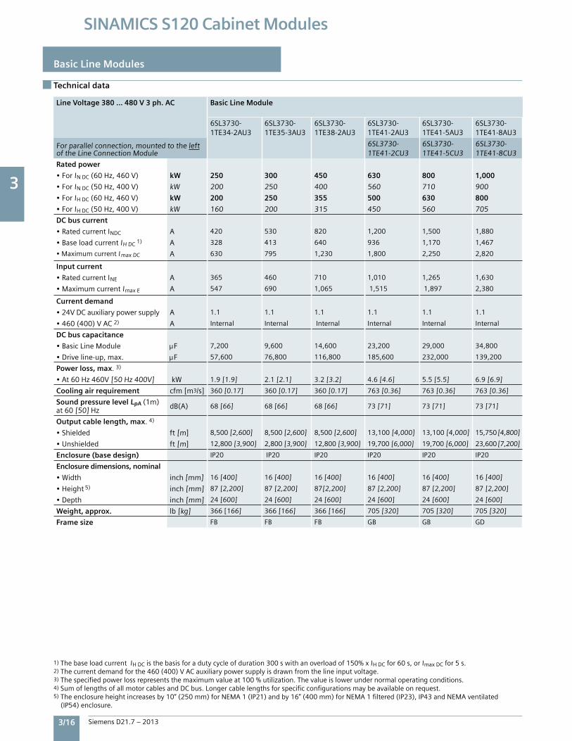
3
3/16 Siemens D21.7 – 2013
SINAMICS S120 Cabinet Modules
Basic Line Modules
Technical data
Line Voltage 380 … 480 V 3 ph. AC Basic Line Module
6SL3730-1TE34-2AU3
6SL3730-1TE35-3AU3
6SL3730-1TE38-2AU3
6SL3730-1TE41-2AU3
6SL3730-1TE41-5AU3
6SL3730-1TE41-8AU3
Forparallelconnection,mountedtotheleftoftheLineConnectionModule
6SL3730-1TE41-2CU3
6SL3730-1TE41-5CU3
6SL3730-1TE41-8CU3
Rated power
•ForINDC(60Hz,460V) kW 250 300 450 630 800 1,000
•ForINDC(50Hz,400V) kW 200 250 400 560 710 900
•ForIHDC(60Hz,460V) kW 200 250 355 500 630 800
•ForIHDC(50Hz,400V) kW 160 200 315 450 560 705
DC bus current
•RatedcurrentINDC A 420 530 820 1,200 1,500 1,880
•BaseloadcurrentIHDC1) A 328 413 640 936 1,170 1,467
•MaximumcurrentImaxDC A 630 795 1,230 1,800 2,250 2,820
Input current
•RatedcurrentINE A 365 460 710 1,010 1,265 1,630
•MaximumcurrentImaxE A 547 690 1,065 1,515 1,897 2,380
Current demand
•24VDCauxiliarypowersupply A 1.1 1.1 1.1 1.1 1.1 1.1
•460(400)VAC2) A Internal Internal Internal Internal Internal Internal
DC bus capacitance
•BasicLineModule F 7,200 9,600 14,600 23,200 29,000 34,800
•Driveline-up,max. F 57,600 76,800 116,800 185,600 232,000 139,200
Power loss, max.3)
•At60Hz460V[50Hz400V] kW 1.9[1.9] 2.1[2.1] 3.2[3.2] 4.6[4.6] 5.5[5.5] 6.9[6.9]
Cooling air requirement cfm[m3/s] 360[0.17] 360[0.17] 360[0.17] 763[0.36] 763[0.36] 763[0.36]
Sound pressure level LpA(1m)at60[50]Hz dB(A) 68[66] 68[66] 68[66] 73[71] 73[71] 73[71]
Output cable length, max.4)
•Shielded ft[m] 8,500[2,600] 8,500[2,600] 8,500[2,600] 13,100[4,000] 13,100[4,000] 15,750[4,800]
•Unshielded ft[m] 12,800[3,900] 2,800[3,900] 12,800[3,900] 19,700[6,000] 19,700[6,000] 23,600[7,200]
Enclosure (base design) IP20 IP20 IP20 IP20 IP20 IP20
Enclosure dimensions, nominal
•Width inch[mm] 16[400] 16[400] 16[400] 16[400] 16[400] 16[400]
•Height 5) inch[mm] 87[2,200] 87[2,200] 87[2,200] 87[2,200] 87[2,200] 87[2,200]
•Depth inch[mm] 24[600] 24[600] 24[600] 24[600] 24[600] 24[600]
Weight, approx. lb[kg] 366[166] 366[166] 366[166] 705[320] 705[320] 705[320]
Frame size FB FB FB GB GB GD
1)ThebaseloadcurrentIHDCisthebasisforadutycycleofduration300swithanoverloadof150%xIHDCfor60s,orImaxDCfor5s.2)Thecurrentdemandforthe460(400)VACauxiliarypowersupplyisdrawnfromthelineinputvoltage.3)Thespecifiedpowerlossrepresentsthemaximumvalueat100%utilization.Thevalueislowerundernormaloperatingconditions.4)SumoflengthsofallmotorcablesandDCbus.Longercablelengthsforspecificconfigurationsmaybeavailableonrequest.5)Theenclosureheightincreasesby10”(250mm)forNEMA1(IP21)andby16”(400mm)forNEMA1filtered(IP23),IP43andNEMAventilated(IP54)enclosure.
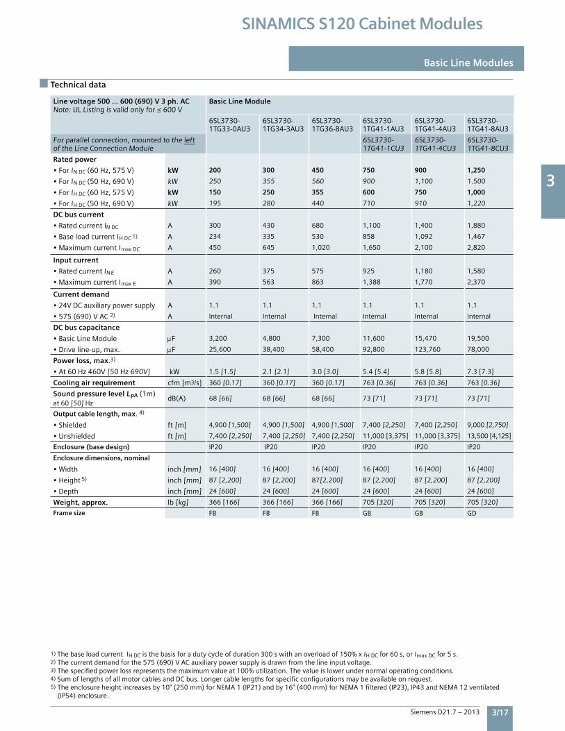
3
Siemens D21.7 – 2013 3/17
SINAMICS S120 Cabinet Modules
Technical data
Basic Line Modules
Line voltage 500 … 600 (690) V 3 ph. ACNote:ULListingisvalidonlyfor≤600V
Basic Line Module
6SL3730-1TG33-0AU3
6SL3730-1TG34-3AU3
6SL3730-1TG36-8AU3
6SL3730-1TG41-1AU3
6SL3730-1TG41-4AU3
6SL3730-1TG41-8AU3
Forparallelconnection,mountedtotheleftoftheLineConnectionModule
6SL3730-1TG41-1CU3
6SL3730-1TG41-4CU3
6SL3730-1TG41-8CU3
Rated power
•ForINDC(60Hz,575V) kW 200 300 450 750 900 1,250
•ForINDC(50Hz,690V) kW 250 355 560 900 1,100 1.500
•ForIHDC(60Hz,575V) kW 150 250 355 600 750 1,000
•ForIHDC(50Hz,690V) kW 195 280 440 710 910 1,220
DC bus current
•RatedcurrentINDC A 300 430 680 1,100 1,400 1,880
•BaseloadcurrentIHDC1) A 234 335 530 858 1,092 1,467
•MaximumcurrentImaxDC A 450 645 1,020 1,650 2,100 2,820
Input current
•RatedcurrentIN E A 260 375 575 925 1,180 1,580
•MaximumcurrentImaxE A 390 563 863 1,388 1,770 2,370
Current demand
•24VDCauxiliarypowersupply A 1.1 1.1 1.1 1.1 1.1 1.1
•575(690)VAC2) A Internal Internal Internal Internal Internal Internal
DC bus capacitance
•BasicLineModule F 3,200 4,800 7,300 11,600 15,470 19,500
•Driveline-up,max. F 25,600 38,400 58,400 92,800 123,760 78,000
Power loss, max.3)
•At60Hz460V[50Hz690V] kW 1.5[1.5] 2.1[2.1] 3.0[3.0] 5.4[5.4] 5.8[5.8] 7.3[7.3]
Cooling air requirement cfm[m3/s] 360[0.17] 360[0.17] 360[0.17] 763[0.36] 763[0.36] 763[0.36]
Sound pressure level LpA(1m)at60[50]Hz
dB(A) 68[66] 68[66] 68[66] 73[71] 73[71] 73[71]
Output cable length, max.4)
•Shielded ft[m] 4,900[1,500] 4,900[1,500] 4,900[1,500] 7,400[2,250] 7,400[2,250] 9,000[2,750]
•Unshielded ft[m] 7,400[2,250] 7,400[2,250] 7,400[2,250] 11,000[3,375] 11,000[3,375] 13,500[4,125]
Enclosure (base design) IP20 IP20 IP20 IP20 IP20 IP20
Enclosure dimensions, nominal
•Width inch[mm] 16[400] 16[400] 16[400] 16[400] 16[400] 16[400]
•Height 5) inch[mm] 87[2,200] 87[2,200] 87[2,200] 87[2,200] 87[2,200] 87[2,200]
•Depth inch[mm] 24[600] 24[600] 24[600] 24[600] 24[600] 24[600]
Weight, approx. lb[kg] 366[166] 366[166] 366[166] 705[320] 705[320] 705[320]
Frame size FB FB FB GB GB GD
1)ThebaseloadcurrentIHDCisthebasisforadutycycleofduration300swithanoverloadof150%xIHDCfor60s,orImaxDCfor5s.2)Thecurrentdemandforthe575(690)VACauxiliarypowersupplyisdrawnfromthelineinputvoltage.3)Thespecifiedpowerlossrepresentsthemaximumvalueat100%utilization.Thevalueislowerundernormaloperatingconditions.4)SumoflengthsofallmotorcablesandDCbus.Longercablelengthsforspecificconfigurationsmaybeavailableonrequest.5)Theenclosureheightincreasesby10”(250mm)forNEMA1(IP21)andby16”(400mm)forNEMA1filtered(IP23),IP43andNEMA12ventilated(IP54)enclosure.
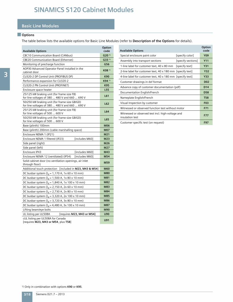
3
3/18 Siemens D21.7 – 2013
SINAMICS S120 Cabinet Modules
Basic Line Modules
Options
ThetablebelowliststheavailableoptionsforBasicLineModules(refertoDescription of the Optionsfordetails).
Available Options Optioncode
CBC10CommunicationBoard(CANbus) G20 1)
CBE20CommunicationBoard(Ethernet) G33 1)
Monitoringofprechargefunction G56
AOP30AdvancedOperatorPanelinstalledinthecabinetdoor
K08 1)
CU320-2DPControlUnit(PROFIBUSDP) K90
PerformanceexpansionforCU320-2 K94 1)
CU320-2PNControlUnit(PROFINET) K95
Enclosurespaceheater L55
25/125kWbrakingunit(forframesizeFB)forlinevoltagesof380...480Vand660...690V
L61
50/250kWbrakingunit(forframesizeGB/GD)forlinevoltagesof380...480Vand660...690V
L62
25/125kWbrakingunit(forframesizeFB)forlinevoltagesof500...600V
L64
50/250kWbrakingunit(forframesizeGB/GD)forlinevoltagesof500...600V
L65
Base(plinth)100mm M06
Base(plinth)200mm(cablemarshallingspace) M07
EnclosureNEMA1(IP21) M21
EnclosureNEMA1filtered(IP23)[includesM60] M23
Sidepanel(right) M26
Sidepanel(left) M27
EnclosureIP43[includesM60] M43
EnclosureNEMA12(ventilated)(IP54)[includesM60] M54
Solidcabinetdoor(noventilationopenings,airinletthroughfloor)
M59
Additionaltouchprotection[includedinM23, M43 & M54] M60
DCbusbarsystem(Id=1,170A,1x60x10mm) M80
DCbusbarsystem(Id=1,500A,1x80x10mm) M81
DCbusbarsystem(Id=1,840A,1x100x10mm) M82
DCbusbarsystem(Id=2,150A,2x60x10mm) M83
DCbusbarsystem(Id=2,730A,2x80x10mm) M84
DCbusbarsystem(Id=3,320A,2x100x10mm) M85
DCbusbarsystem(Id=3,720A,3x80x10mm) M86
DCbusbarsystem(Id=4,480A,3x100x10mm) M87
Liftingbeam/eyebolts M90
ULlistingperUL508A[requiresM23, M43 or M54] U90
cULlistingperUL508AforCanada[requiresM23, M43 or M54,plusT58]
U91
Available Options Optioncode
Specialenclosurepaintcolor[specifycolor] Y09
Assemblyintotransportsections[specifysections] Y11
1-linelabelforcustomertext,40x80mm[specifytext] Y31
2-linelabelforcustomertext,40x180mm[specifytext] Y32
4-linelabelforcustomertext,40x180mm[specifytext] Y33
Customerdrawingsindxfformat D02
Advancecopyofcustomerdocumentation(pdf) D14
DocumentationEnglish/French D58
NameplateEnglish/French T58
VisualInspectionbycustomer F03
Witnessedorobservedfunctiontestwithoutmotor F71
Witnessedorobservedtestincl.high-voltageandinsulationtest
F77
Customerspecifictest(onrequest) F97
1)OnlyincombinationwithoptionsK90orK95.
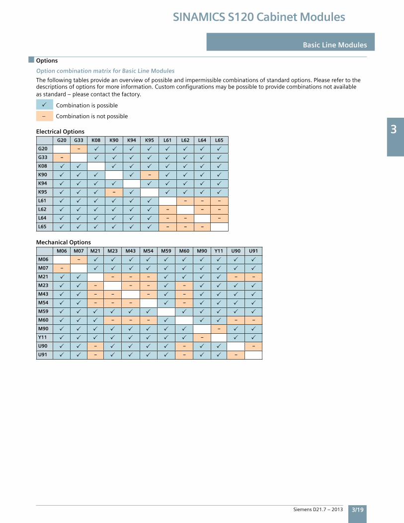
3
Siemens D21.7 – 2013 3/19
SINAMICS S120 Cabinet Modules
Options
Basic Line Modules
Option combination matrix for Basic Line Modules
Thefollowingtablesprovideanoverviewofpossibleandimpermissiblecombinationsofstandardoptions.Pleaserefertothedescriptionsofoptionsformoreinformation.Customconfigurationsmaybepossibletoprovidecombinationsnotavailableasstandard–pleasecontactthefactory.
Combinationispossible
–Combinationisnotpossible
Electrical OptionsG20 G33 K08 K90 K94 K95 L61 L62 L64 L65
G20 –
G33 –
K08
K90 –
K94
K95 –
L61 – – –
L62 – – –
L64 – – –
L65 – – –
Mechanical OptionsM06 M07 M21 M23 M43 M54 M59 M60 M90 Y11 U90 U91
M06 –
M07 –
M21 – – – – –
M23 – – – –
M43 – – – –
M54 – – – –
M59
M60 – – – – –
M90 –
Y11 –
U90 – – –
U91 – – –
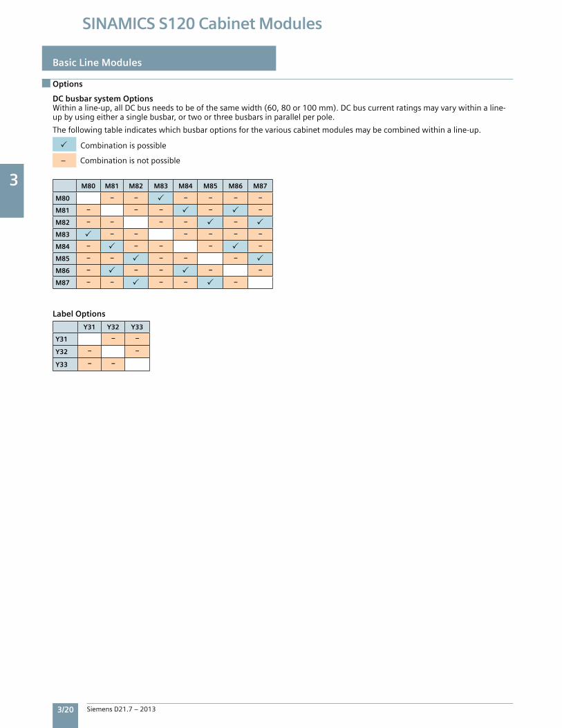
3
3/20 Siemens D21.7 – 2013
SINAMICS S120 Cabinet Modules
DC busbar system OptionsWithinaline-up,allDCbusneedstobeofthesamewidth(60,80or100mm).DCbuscurrentratingsmayvarywithinaline-upbyusingeitherasinglebusbar,ortwoorthreebusbarsinparallelperpole.
Thefollowingtableindicateswhichbusbaroptionsforthevariouscabinetmodulesmaybecombinedwithinaline-up.
Combinationispossible
–Combinationisnotpossible
M80 M81 M82 M83 M84 M85 M86 M87
M80 – – – – – –
M81 – – – – –
M82 – – – – –
M83 – – – – – –
M84 – – – – –
M85 – – – – –
M86 – – – – –
M87 – – – – –
Y31 Y32 Y33
Y31 – –
Y32 – –
Y33 – –
Label Options
Basic Line Modules
Options
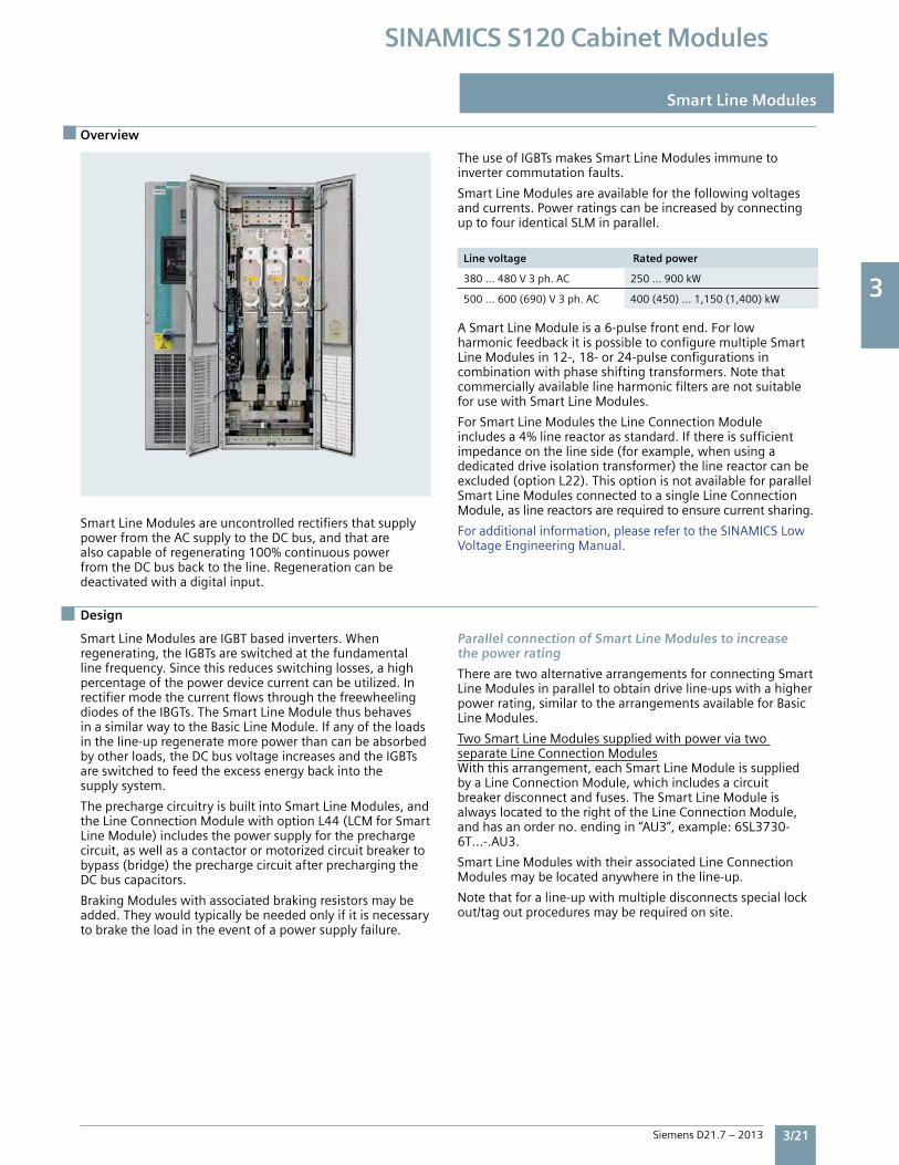
3
Siemens D21.7 – 2013 3/21
SINAMICS S120 Cabinet Modules
Overview
Smart Line Modules
SmartLineModulesareuncontrolledrectifiersthatsupplypowerfromtheACsupplytotheDCbus,andthatarealsocapableofregenerating100%continuouspowerfromtheDCbusbacktotheline.Regenerationcanbedeactivatedwithadigitalinput.
TheuseofIGBTsmakesSmartLineModulesimmunetoinvertercommutationfaults.
SmartLineModulesareavailableforthefollowingvoltagesandcurrents.PowerratingscanbeincreasedbyconnectinguptofouridenticalSLMinparallel.
Line voltage Rated power
380…480V3ph.AC 250…900kW
500…600(690)V3ph.AC 400(450)…1,150(1,400)kW
ASmartLineModuleisa6-pulsefrontend.ForlowharmonicfeedbackitispossibletoconfiguremultipleSmartLineModulesin12-,18-or24-pulseconfigurationsincombinationwithphaseshiftingtransformers.NotethatcommerciallyavailablelineharmonicfiltersarenotsuitableforusewithSmartLineModules.
ForSmartLineModulestheLineConnectionModuleincludesa4%linereactorasstandard.Ifthereissufficientimpedanceonthelineside(forexample,whenusingadedicateddriveisolationtransformer)thelinereactorcanbeexcluded(optionL22).ThisoptionisnotavailableforparallelSmartLineModulesconnectedtoasingleLineConnectionModule,aslinereactorsarerequiredtoensurecurrentsharing.
Foradditionalinformation,pleaserefertotheSINAMICSLowVoltageEngineeringManual.
SmartLineModulesareIGBTbasedinverters.Whenregenerating,theIGBTsareswitchedatthefundamentallinefrequency.Sincethisreducesswitchinglosses,ahighpercentageofthepowerdevicecurrentcanbeutilized.InrectifiermodethecurrentflowsthroughthefreewheelingdiodesoftheIBGTs.TheSmartLineModulethusbehavesinasimilarwaytotheBasicLineModule.Ifanyoftheloadsintheline-upregeneratemorepowerthancanbeabsorbedbyotherloads,theDCbusvoltageincreasesandtheIGBTsareswitchedtofeedtheexcessenergybackintothesupplysystem.
TheprechargecircuitryisbuiltintoSmartLineModules,andtheLineConnectionModulewithoptionL44(LCMforSmartLineModule)includesthepowersupplyfortheprechargecircuit,aswellasacontactorormotorizedcircuitbreakertobypass(bridge)theprechargecircuitafterprechargingtheDCbuscapacitors.
BrakingModuleswithassociatedbrakingresistorsmaybeadded.Theywouldtypicallybeneededonlyifitisnecessarytobraketheloadintheeventofapowersupplyfailure.
Parallel connection of Smart Line Modules to increasethe power rating
TherearetwoalternativearrangementsforconnectingSmartLineModulesinparalleltoobtaindriveline-upswithahigherpowerrating,similartothearrangementsavailableforBasicLineModules.
TwoSmartLineModulessuppliedwithpowerviatwoseparateLineConnectionModulesWiththisarrangement,eachSmartLineModuleissuppliedbyaLineConnectionModule,whichincludesacircuitbreakerdisconnectandfuses.TheSmartLineModuleisalwayslocatedtotherightoftheLineConnectionModule,andhasanorderno.endingin“AU3”,example:6SL3730-6T…-.AU3.
SmartLineModuleswiththeirassociatedLineConnectionModulesmaybelocatedanywhereintheline-up.
Notethatforaline-upwithmultipledisconnectsspeciallockout/tagoutproceduresmayberequiredonsite.
Design
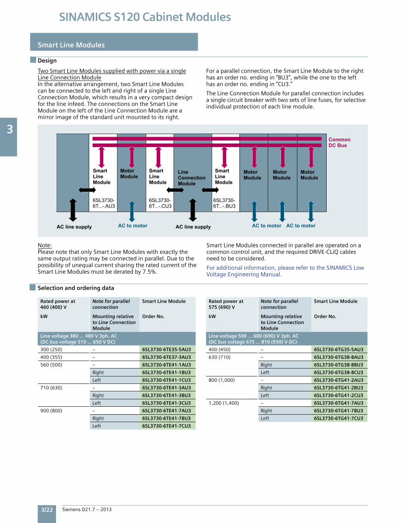
3
3/22 Siemens D21.7 – 2013
SINAMICS S120 Cabinet Modules
Smart Line Modules
Design
TwoSmartLineModulessuppliedwithpowerviaasingleLineConnectionModuleInthealternativearrangement,twoSmartLineModulescanbeconnectedtotheleftandrightofasingleLineConnectionModule,whichresultsinaverycompactdesignforthelineinfeed.TheconnectionsontheSmartLineModuleontheleftoftheLineConnectionModuleareamirrorimageofthestandardunitmountedtoitsright.
Foraparallelconnection,theSmartLineModuletotherighthasanorderno.endingin“BU3”,whiletheonetothelefthasanorderno.endingin“CU3.”
TheLineConnectionModuleforparallelconnectionincludesasinglecircuitbreakerwithtwosetsoflinefuses,forselectiveindividualprotectionofeachlinemodule.
Note:PleasenotethatonlySmartLineModuleswithexactlythesameoutputratingmaybeconnectedinparallel.DuetothepossibilityofunequalcurrentsharingtheratedcurrentoftheSmartLineModulesmustbederatedby7.5%.
SmartLineModulesconnectedinparallelareoperatedonacommoncontrolunit,andtherequiredDRIVE-CLiQcablesneedtobeconsidered.
Foradditionalinformation,pleaserefertotheSINAMICSLowVoltageEngineeringManual.
Rated power at460 (400) V
kW
Note for parallelconnection
Mounting relativeto Line ConnectionModule
Smart Line Module
Order No.
Line voltage 380 … 480 V 3ph. AC(DC bus voltage 510 … 650 V DC)
300(250) – 6SL3730-6TE35-5AU3
400(355) – 6SL3730-6TE37-3AU3
560(500) – 6SL3730-6TE41-1AU3
Right 6SL3730-6TE41-1BU3
Left 6SL3730-6TE41-1CU3
710(630) – 6SL3730-6TE41-3AU3
Right 6SL3730-6TE41-3BU3
Left 6SL3730-6TE41-3CU3
900(800) – 6SL3730-6TE41-7AU3
Right 6SL3730-6TE41-7BU3
Left 6SL3730-6TE41-7CU3
Rated power at575 (690) V
kW
Note for parallelconnection
Mounting relativeto Line ConnectionModule
Smart Line Module
Order No.
Line voltage 500 … 600 (690) V 3ph. AC(DC bus voltage 675 … 810 (930) V DC)
400(450) – 6SL3730-6TG35-5AU3
630(710) – 6SL3730-6TG38-8AU3
Right 6SL3730-6TG38-8BU3
Left 6SL3730-6TG38-8CU3
800(1,000) – 6SL3730-6TG41-2AU3
Right 6SL3730-6TG41-2BU3
Left 6SL3730-6TG41-2CU3
1,200(1,400) – 6SL3730-6TG41-7AU3
Right 6SL3730-6TG41-7BU3
Left 6SL3730-6TG41-7CU3
Selection and ordering data
Common DC Bus
AC to motor AC to motor AC to motor
LineConnectionModule
LineConnectionModule
SmartLineModule
SmartLineModule
SmartLineModule
Motor Module
Motor Module
Motor Module
Motor Module
6SL3730-6T...-.AU3
6SL3730-6T...-.CU3
6SL3730-6T...-.BU3
AC line supply AC line supply
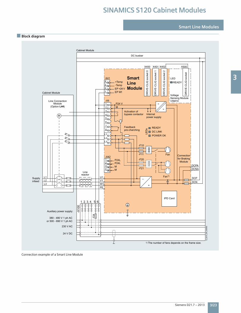
3
Siemens D21.7 – 2013 3/23
SINAMICS S120 Cabinet Modules
Block diagram
Smart Line Modules
ConnectionexampleofaSmartLineModule
P24L P24L
4321-X42
MM
1 2 3 4 5 6
Activation ofbypass contactor Internal
power supply
1) The number of fans depends on the frame size.
G_D
213_
EN
_000
58c
Fan
Fan1)
24 V DC
230 V AC
380 - 480 V 1 ph ACor 500 - 690 V 1 ph AC
Feedbackpre-charching
Supplyinfeed
DC busbar
Linereactor
Connectionfor Braking
Module
Auxiliary power supply:
DR
IVE
-CLi
Q s
ocke
t 0
DR
IVE
-CLi
Q s
ocke
t 1
DR
IVE
-CLi
Q s
ocke
t 2
DR
IVE
-CLi
Q s
ocke
t
IPD Card
2
VoltageSensing Module VSM10
LED READY
Cabinet Module
Cabinet Module
Line Connection Module
(Option L44)
Smart Line Module
=
~
-F21
-F20
-F11
-F10
=
=M P24 V
7 8
5 6
3 4
1 -X9
L1
L3L2
11234-X41
EP M+24 VEP
DCNADCPA
DCNDCP
PEW1V1U1
-F24
-X10
0
Temp-Temp+
X400
X401 X402 X500
DC LINK POWER OK
READY
LED
s
L3L2L1
M
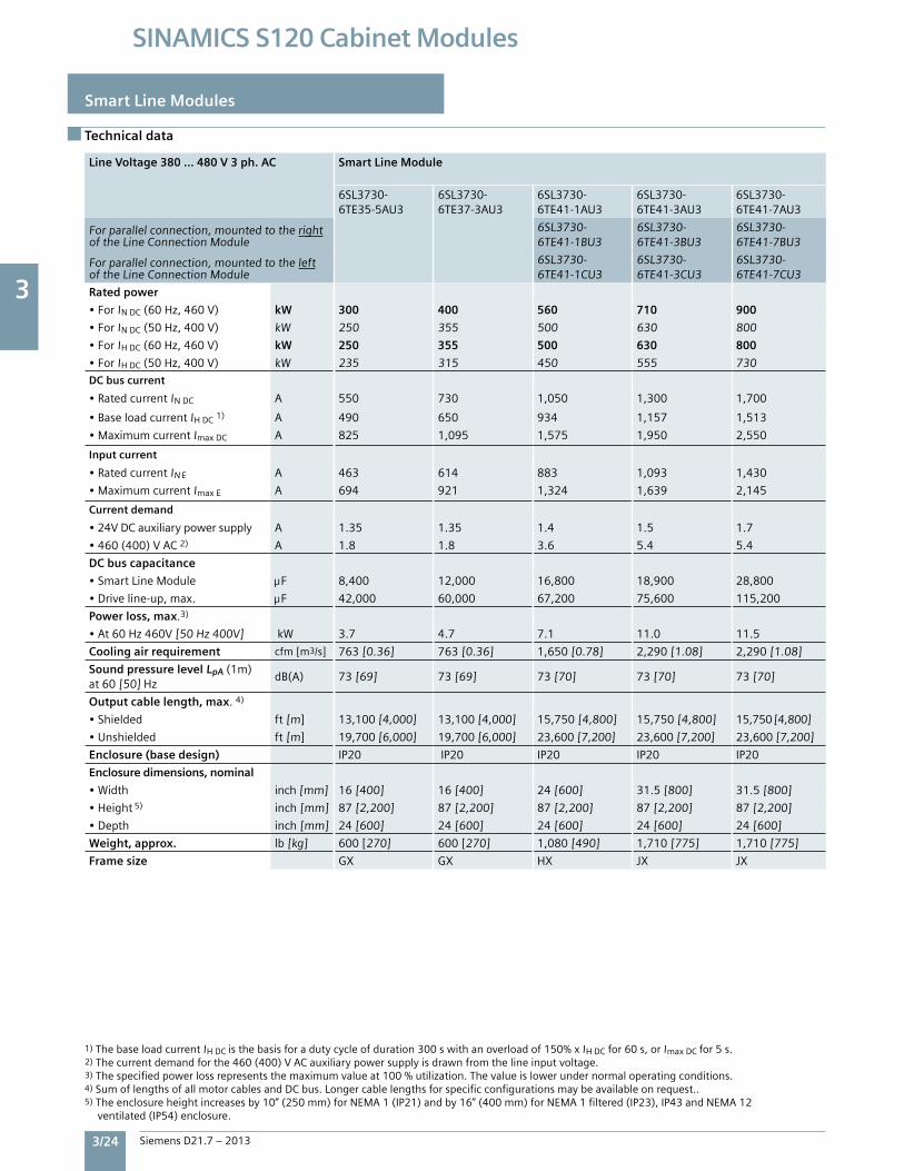
3
3/24 Siemens D21.7 – 2013
SINAMICS S120 Cabinet Modules
Smart Line Modules
Technical data
Line Voltage 380 … 480 V 3 ph. AC Smart Line Module
6SL3730-6TE35-5AU3
6SL3730-6TE37-3AU3
6SL3730-6TE41-1AU3
6SL3730-6TE41-3AU3
6SL3730-6TE41-7AU3
Forparallelconnection,mountedtotherightoftheLineConnectionModule
6SL3730-6TE41-1BU3
6SL3730-6TE41-3BU3
6SL3730-6TE41-7BU3
Forparallelconnection,mountedtotheleftoftheLineConnectionModule
6SL3730-6TE41-1CU3
6SL3730-6TE41-3CU3
6SL3730-6TE41-7CU3
Rated power
•ForINDC(60Hz,460V) kW 300 400 560 710 900
•ForINDC(50Hz,400V) kW 250 355 500 630 800
•ForIHDC(60Hz,460V) kW 250 355 500 630 800
•ForIHDC(50Hz,400V) kW 235 315 450 555 730
DC bus current
•RatedcurrentINDC A 550 730 1,050 1,300 1,700
•BaseloadcurrentIHDC1) A 490 650 934 1,157 1,513
•MaximumcurrentImaxDC A 825 1,095 1,575 1,950 2,550
Input current
•RatedcurrentIN E A 463 614 883 1,093 1,430
•MaximumcurrentImaxE A 694 921 1,324 1,639 2,145
Current demand
•24VDCauxiliarypowersupply A 1.35 1.35 1.4 1.5 1.7
•460(400)VAC2) A 1.8 1.8 3.6 5.4 5.4
DC bus capacitance
•SmartLineModule F 8,400 12,000 16,800 18,900 28,800
•Driveline-up,max. F 42,000 60,000 67,200 75,600 115,200
Power loss, max.3)
•At60Hz460V[50Hz400V] kW 3.7 4.7 7.1 11.0 11.5
Cooling air requirement cfm[m3/s] 763[0.36] 763[0.36] 1,650[0.78] 2,290[1.08] 2,290[1.08]
Sound pressure level LpA(1m)at60[50]Hz
dB(A) 73[69] 73[69] 73[70] 73[70] 73[70]
Output cable length, max.4)
•Shielded ft[m] 13,100[4,000] 13,100[4,000] 15,750[4,800] 15,750[4,800] 15,750[4,800]
•Unshielded ft[m] 19,700[6,000] 19,700[6,000] 23,600[7,200] 23,600[7,200] 23,600[7,200]
Enclosure (base design) IP20 IP20 IP20 IP20 IP20
Enclosure dimensions, nominal
•Width inch[mm] 16[400] 16[400] 24[600] 31.5[800] 31.5[800]
•Height 5) inch[mm] 87[2,200] 87[2,200] 87[2,200] 87[2,200] 87[2,200]
•Depth inch[mm] 24[600] 24[600] 24[600] 24[600] 24[600]
Weight, approx. lb[kg] 600[270] 600[270] 1,080[490] 1,710[775] 1,710[775]
Frame size GX GX HX JX JX
1)ThebaseloadcurrentIHDCisthebasisforadutycycleofduration300swithanoverloadof150%xIHDCfor60s,orImaxDCfor5s.2)Thecurrentdemandforthe460(400)VACauxiliarypowersupplyisdrawnfromthelineinputvoltage.3)Thespecifiedpowerlossrepresentsthemaximumvalueat100%utilization.Thevalueislowerundernormaloperatingconditions.4)SumoflengthsofallmotorcablesandDCbus.Longercablelengthsforspecificconfigurationsmaybeavailableonrequest..5)Theenclosureheightincreasesby10”(250mm)forNEMA1(IP21)andby16”(400mm)forNEMA1filtered(IP23),IP43andNEMA12 ventilated(IP54)enclosure.
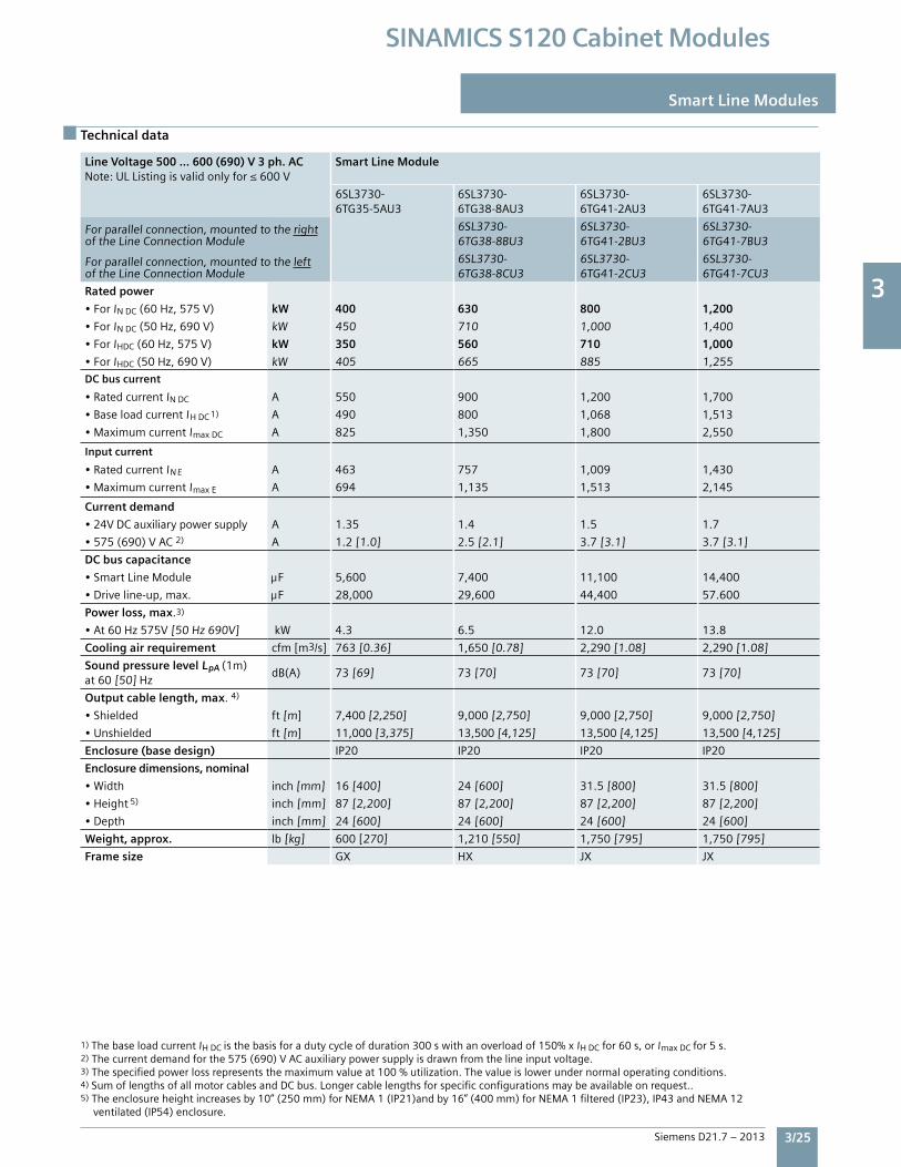
3
Siemens D21.7 – 2013 3/25
SINAMICS S120 Cabinet Modules
Technical data
Smart Line Modules
Line Voltage 500 … 600 (690) V 3 ph. AC Note:ULListingisvalidonlyfor≤600V
Smart Line Module
6SL3730-6TG35-5AU3
6SL3730-6TG38-8AU3
6SL3730-6TG41-2AU3
6SL3730-6TG41-7AU3
Forparallelconnection,mountedtotherightoftheLineConnectionModule
6SL3730-6TG38-8BU3
6SL3730-6TG41-2BU3
6SL3730-6TG41-7BU3
Forparallelconnection,mountedtotheleftoftheLineConnectionModule
6SL3730-6TG38-8CU3
6SL3730-6TG41-2CU3
6SL3730-6TG41-7CU3
Rated power
•ForINDC(60Hz,575V) kW 400 630 800 1,200
•ForINDC(50Hz,690V) kW 450 710 1,000 1,400
•ForIHDC(60Hz,575V) kW 350 560 710 1,000
•ForIHDC(50Hz,690V) kW 405 665 885 1,255
DC bus current
•RatedcurrentINDC A 550 900 1,200 1,700
•BaseloadcurrentIHDC 1) A 490 800 1,068 1,513
•MaximumcurrentImaxDC A 825 1,350 1,800 2,550
Input current
•RatedcurrentIN E A 463 757 1,009 1,430
•MaximumcurrentImaxE A 694 1,135 1,513 2,145
Current demand
•24VDCauxiliarypowersupply A 1.35 1.4 1.5 1.7
•575(690)VAC2) A 1.2[1.0] 2.5[2.1] 3.7[3.1] 3.7[3.1]
DC bus capacitance
•SmartLineModule F 5,600 7,400 11,100 14,400
•Driveline-up,max. F 28,000 29,600 44,400 57.600
Power loss, max.3)
•At60Hz575V[50Hz690V] kW 4.3 6.5 12.0 13.8
Cooling air requirement cfm[m3/s] 763[0.36] 1,650[0.78] 2,290[1.08] 2,290[1.08]
Sound pressure level LpA(1m)at60[50]Hz
dB(A) 73[69] 73[70] 73[70] 73[70]
Output cable length, max.4)
•Shielded ft[m] 7,400[2,250] 9,000[2,750] 9,000[2,750] 9,000[2,750]
•Unshielded ft[m] 11,000[3,375] 13,500[4,125] 13,500[4,125] 13,500[4,125]
Enclosure (base design) IP20 IP20 IP20 IP20
Enclosure dimensions, nominal
•Width inch[mm] 16[400] 24[600] 31.5[800] 31.5[800]
•Height 5) inch[mm] 87[2,200] 87[2,200] 87[2,200] 87[2,200]
•Depth inch[mm] 24[600] 24[600] 24[600] 24[600]
Weight, approx. lb[kg] 600[270] 1,210[550] 1,750[795] 1,750[795]
Frame size GX HX JX JX
1)ThebaseloadcurrentIHDCisthebasisforadutycycleofduration300swithanoverloadof150%xIHDCfor60s,orImaxDCfor5s.2)Thecurrentdemandforthe575(690)VACauxiliarypowersupplyisdrawnfromthelineinputvoltage.3)Thespecifiedpowerlossrepresentsthemaximumvalueat100%utilization.Thevalueislowerundernormaloperatingconditions.4)SumoflengthsofallmotorcablesandDCbus.Longercablelengthsforspecificconfigurationsmaybeavailableonrequest..5)Theenclosureheightincreasesby10”(250mm)forNEMA1(IP21)andby16”(400mm)forNEMA1filtered(IP23),IP43andNEMA12 ventilated(IP54)enclosure.
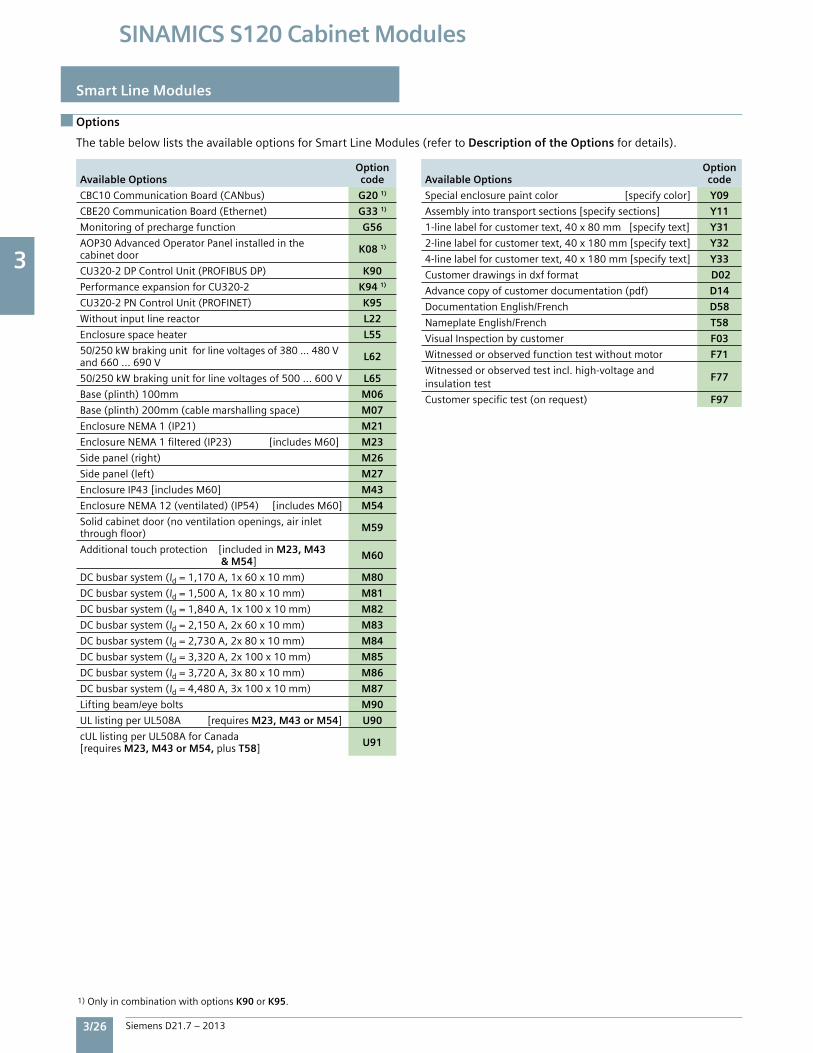
3
3/26 Siemens D21.7 – 2013
SINAMICS S120 Cabinet Modules
Smart Line Modules
Options
ThetablebelowliststheavailableoptionsforSmartLineModules(refertoDescription of the Options fordetails).
Available Options Optioncode
CBC10CommunicationBoard(CANbus) G20 1)
CBE20CommunicationBoard(Ethernet) G33 1)
Monitoringofprechargefunction G56
AOP30AdvancedOperatorPanelinstalledinthecabinetdoor K08 1)
CU320-2DPControlUnit(PROFIBUSDP) K90
PerformanceexpansionforCU320-2 K94 1)
CU320-2PNControlUnit(PROFINET) K95
Withoutinputlinereactor L22
Enclosurespaceheater L55
50/250kWbrakingunitforlinevoltagesof380...480Vand660...690V L62
50/250kWbrakingunitforlinevoltagesof500...600V L65
Base(plinth)100mm M06
Base(plinth)200mm(cablemarshallingspace) M07
EnclosureNEMA1(IP21) M21
EnclosureNEMA1filtered(IP23)[includesM60] M23
Sidepanel(right) M26
Sidepanel(left) M27
EnclosureIP43[includesM60] M43
EnclosureNEMA12(ventilated)(IP54)[includesM60] M54
Solidcabinetdoor(noventilationopenings,airinletthroughfloor) M59
Additionaltouchprotection[includedinM23, M43 & M54] M60
DCbusbarsystem(Id=1,170A,1x60x10mm) M80
DCbusbarsystem(Id=1,500A,1x80x10mm) M81
DCbusbarsystem(Id=1,840A,1x100x10mm) M82
DCbusbarsystem(Id=2,150A,2x60x10mm) M83
DCbusbarsystem(Id=2,730A,2x80x10mm) M84
DCbusbarsystem(Id=3,320A,2x100x10mm) M85
DCbusbarsystem(Id=3,720A,3x80x10mm) M86
DCbusbarsystem(Id=4,480A,3x100x10mm) M87
Liftingbeam/eyebolts M90
ULlistingperUL508A[requiresM23, M43 or M54] U90
cULlistingperUL508AforCanada[requiresM23, M43 or M54,plusT58] U91
Available Options Optioncode
Specialenclosurepaintcolor[specifycolor] Y09
Assemblyintotransportsections[specifysections] Y11
1-linelabelforcustomertext,40x80mm[specifytext] Y31
2-linelabelforcustomertext,40x180mm[specifytext] Y32
4-linelabelforcustomertext,40x180mm[specifytext] Y33
Customerdrawingsindxfformat D02
Advancecopyofcustomerdocumentation(pdf) D14
DocumentationEnglish/French D58
NameplateEnglish/French T58
VisualInspectionbycustomer F03
Witnessedorobservedfunctiontestwithoutmotor F71
Witnessedorobservedtestincl.high-voltageandinsulationtest
F77
Customerspecifictest(onrequest) F97
1)OnlyincombinationwithoptionsK90orK95.
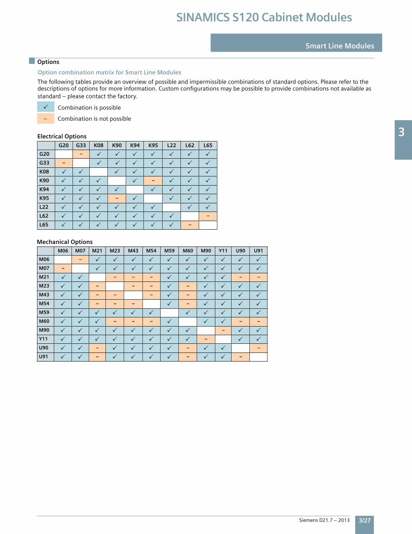
3
Siemens D21.7 – 2013 3/27
SINAMICS S120 Cabinet Modules
Options
Smart Line Modules
Option combination matrix for Smart Line Modules
Thefollowingtablesprovideanoverviewofpossibleandimpermissiblecombinationsofstandardoptions.Pleaserefertothedescriptionsofoptionsformoreinformation.Customconfigurationsmaybepossibletoprovidecombinationsnotavailableasstandard–pleasecontactthefactory.
Combinationispossible
–Combinationisnotpossible
Electrical Options
G20 G33 K08 K90 K94 K95 L22 L62 L65
G20 –
G33 –
K08
K90 –
K94
K95 –
L22
L62 –
L65 –
Mechanical OptionsM06 M07 M21 M23 M43 M54 M59 M60 M90 Y11 U90 U91
M06 –
M07 –
M21 – – – – –
M23 – – – –
M43 – – – –
M54 – – – –
M59
M60 – – – – –
M90 –
Y11 –
U90 – – –
U91 – – –

3
3/28 Siemens D21.7 – 2013
SINAMICS S120 Cabinet Modules
Smart Line Modules
Options
DC busbar system OptionsWithinaline-up,allDCbusneedstobeofthesamewidth(60,80or100mm).DCbuscurrentratingsmayvarywithinaline-upbyusingeitherasinglebusbar,ortwoorthreebusbarsinparallelperpole.
Thefollowingtableindicateswhichbusbaroptionsforthevariouscabinetmodulesmaybecombinedwithinaline-up.
Combinationispossible
–Combinationisnotpossible
M80 M81 M82 M83 M84 M85 M86 M87
M80 – – – – – –
M81 – – – – –
M82 – – – – –
M83 – – – – – –
M84 – – – – –
M85 – – – – –
M86 – – – – –
M87 – – – – –
Y31 Y32 Y33
Y31 – –
Y32 – –
Y33 – –
Label Options
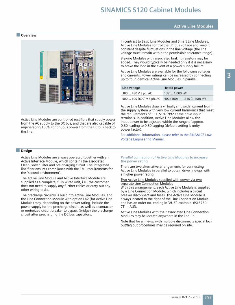
3
Siemens D21.7 – 2013 3/29
SINAMICS S120 Cabinet Modules
Overview
Design
Active Line Modules
ActiveLineModulesarecontrolledrectifiersthatsupplypowerfromtheACsupplytotheDCbus,andthatarealsocapableofregenerating100%continuouspowerfromtheDCbusbacktotheline.
IncontrasttoBasicLineModulesandSmartLineModules,ActiveLineModulescontroltheDCbusvoltageandkeepitconstantdespitefluctuationsinthelinevoltage(thelinevoltagemustremainwithinthepermissibletolerancerange).
BrakingModuleswithassociatedbrakingresistorsmaybeadded.Theywouldtypicallybeneededonlyifitisnecessarytobraketheloadintheeventofapowersupplyfailure.
ActiveLineModulesareavailableforthefollowingvoltagesandcurrents.PowerratingscanbeincreasedbyconnectinguptofouridenticalActiveLineModulesinparallel.
Line voltage Rated power
380…480V3ph.AC 132…1,000kW
500…600(690)V3ph.AC 400(560)…1,150(1,400)kW
ActiveLineModulesdrawavirtuallysinusoidalcurrentfromthesupplysystemwithverylowcurrentharmonicsthatmeettherequirementsofIEEE519-1992atthedriveinputterminals.Inaddition,ActiveLineModulesallowtheinputpowertobeadjustedwithintherangeofapprox.0.80leadingto0.80lagging(defaultsettingisunitypowerfactor).
Foradditionalinformation,pleaserefertotheSINAMICSLowVoltageEngineeringManual.
ActiveLineModulesarealwaysoperatedtogetherwithanActiveInterfaceModule,whichcontainstheassociatedCleanPowerFilterandpre-chargingcircuit.TheintegratedlinefilterensurescompliancewiththeEMCrequirementsforthe“secondenvironment”.
TheActiveLineModuleandActiveInterfaceModulearesuppliedasacomplete,fullywiredunit,i.e.,thecustomerdoesnotneedtosupplyanyfurthercablesorcarryoutanyotherwiringtasks.
TheprechargecircuitryisbuiltintoActiveLineModules,andtheLineConnectionModulewithoptionL42(forActiveLineModule)may,dependingonthepowerrating,includethepowersupplyfortheprechargecircuit,aswellasacontactorormotorizedcircuitbreakertobypass(bridge)theprechargecircuitafterprechargingtheDCbuscapacitors.
Parallel connection of Active Line Modules to increasethe power rating
TherearetwoalternativearrangementsforconnectingActiveLineModulesinparalleltoobtaindriveline-upswithahigherpowerrating.
TwoActiveLineModulessuppliedwithpowerviatwoseparateLineConnectionModulesWiththisarrangement,eachActiveLineModuleissuppliedbyaLineConnectionModule,whichincludesacircuitbreakerdisconnectandfuses.TheActiveLineModuleisalwayslocatedtotherightoftheLineConnectionModule,andhasanorderno.endingin“AU3”,example:6SL3730-7T…-.AU3.
ActiveLineModuleswiththeirassociatedLineConnectionModulesmaybelocatedanywhereintheline-up.
Notethatforaline-upwithmultipledisconnectsspeciallockout/tagoutproceduresmayberequiredonsite.
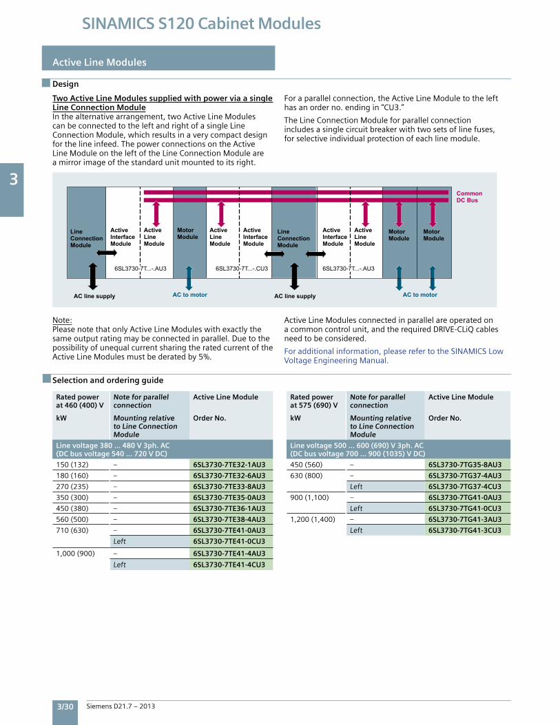
3
3/30 Siemens D21.7 – 2013
SINAMICS S120 Cabinet Modules
Active Line Modules
Design
Two Active Line Modules supplied with power via a single Line Connection ModuleInthealternativearrangement,twoActiveLineModulescanbeconnectedtotheleftandrightofasingleLineConnectionModule,whichresultsinaverycompactdesignforthelineinfeed.ThepowerconnectionsontheActiveLineModuleontheleftoftheLineConnectionModuleareamirrorimageofthestandardunitmountedtoitsright.
Foraparallelconnection,theActiveLineModuletothelefthasanorderno.endingin“CU3.”
TheLineConnectionModuleforparallelconnectionincludesasinglecircuitbreakerwithtwosetsoflinefuses,forselectiveindividualprotectionofeachlinemodule.
Note:PleasenotethatonlyActiveLineModuleswithexactlythesameoutputratingmaybeconnectedinparallel.DuetothepossibilityofunequalcurrentsharingtheratedcurrentoftheActiveLineModulesmustbederatedby5%.
ActiveLineModulesconnectedinparallelareoperatedonacommoncontrolunit,andtherequiredDRIVE-CLiQcablesneedtobeconsidered.
Foradditionalinformation,pleaserefertotheSINAMICSLowVoltageEngineeringManual.
Rated power at 460 (400) V
kW
Note for parallelconnection
Mounting relativeto Line ConnectionModule
Active Line Module
Order No.
Line voltage 380 … 480 V 3ph. AC(DC bus voltage 540 … 720 V DC)
150(132) – 6SL3730-7TE32-1AU3
180(160) – 6SL3730-7TE32-6AU3
270(235) – 6SL3730-7TE33-8AU3
350(300) – 6SL3730-7TE35-0AU3
450(380) – 6SL3730-7TE36-1AU3
560(500) – 6SL3730-7TE38-4AU3
710(630) – 6SL3730-7TE41-0AU3
Left 6SL3730-7TE41-0CU3
1,000(900) – 6SL3730-7TE41-4AU3
Left 6SL3730-7TE41-4CU3
Rated power at 575 (690) V kW
Note for parallelconnection
Mounting relativeto Line ConnectionModule
Active Line Module
Order No.
Line voltage 500 … 600 (690) V 3ph. AC(DC bus voltage 700 … 900 (1035) V DC)
450(560) – 6SL3730-7TG35-8AU3
630(800) – 6SL3730-7TG37-4AU3
Left 6SL3730-7TG37-4CU3
900(1,100) – 6SL3730-7TG41-0AU3
Left 6SL3730-7TG41-0CU3
1,200(1,400) – 6SL3730-7TG41-3AU3
Left 6SL3730-7TG41-3CU3
Selection and ordering guide
Common DC Bus
AC to motor AC to motor
LineConnectionModule
LineConnectionModule
Motor Module
Motor Module
Motor Module
AC line supply AC line supply
ActiveInterfaceModule
ActiveLineModule
ActiveInterfaceModule
ActiveLineModule
ActiveLineModule
ActiveInterfaceModule
6SL3730-7T...-.AU3 6SL3730-7T...-.CU3 6SL3730-7T...-.AU3
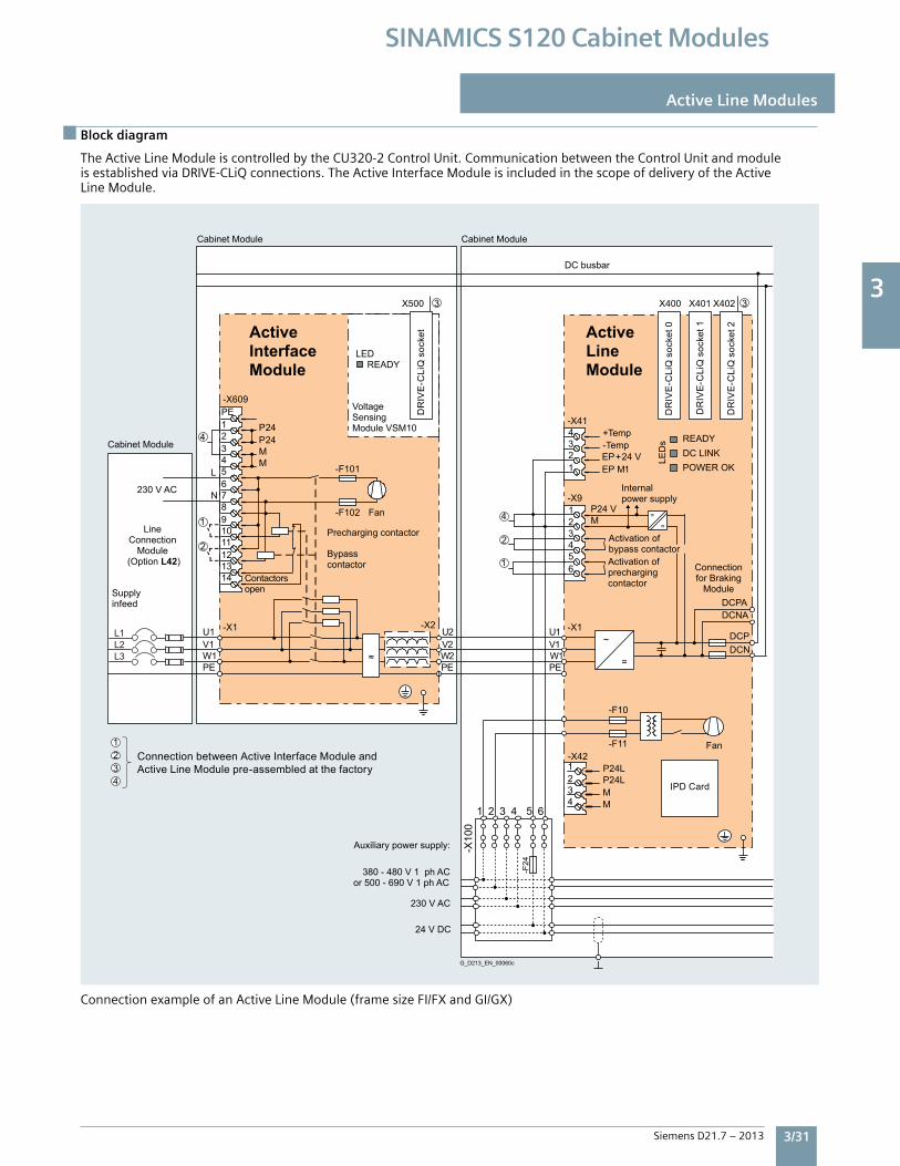
3
Siemens D21.7 – 2013 3/31
SINAMICS S120 Cabinet Modules
Block diagram
Active Line Modules
TheActiveLineModuleiscontrolledbytheCU320-2ControlUnit.CommunicationbetweentheControlUnitandmoduleisestablishedviaDRIVE-CLiQconnections.TheActiveInterfaceModuleisincludedinthescopeofdeliveryoftheActiveLineModule.
ConnectionexampleofanActiveLineModule(framesizeFI/FXandGI/GX)
P24L P24L
4321-X42
MM
1 2 3 4 5 6
Internal power supply
Activation of bypass contactor
DC busbar
Connectionfor Braking
Module
Fan
Activation ofprechargingcontactor
24 V DC
230 V AC
380 - 480 V 1 ph ACor 500 - 690 V 1 ph AC
Auxiliary power supply:
G_D213_EN_00060c
DR
IVE
-CLi
Q s
ocke
t 0
DR
IVE
-CLi
Q s
ocke
t 1
DR
IVE
-CLi
Q s
ocke
t 2
Supplyinfeed
Bypasscontactor
Precharging contactor
Contactorsopen
Fan
DR
IVE
-CLi
Q s
ocke
t
Connection between Active Interface Module and Active Line Module pre-assembled at the factory
Cabinet Module
Active Line Module
=
~
==
PEW1V1U1 -X1
DCNADCPA
DCNDCP
1EP M24 V+EP
MP24 V
4
2
1
1234-X41
654321-X9
3
4
21
X400 X401 X402
230 V AC
Active Interface Module
Cabinet Module
Cabinet Module
Line Connection
Module (Option L42)
Voltage Sensing Module VSM10
LEDREADY
PEW2V2U2
≈
-X2
3
3
X500
PEW1V1U1 -X1
N
LMM
24P24P
14131211109876543
2
4
1
21PE-X609
-F102
-F101
-F11
-F10
-X10
0
-F24
IPD Card
DC LINK POWER OK
READY
LED
sTemp-Temp+
L3L2L1
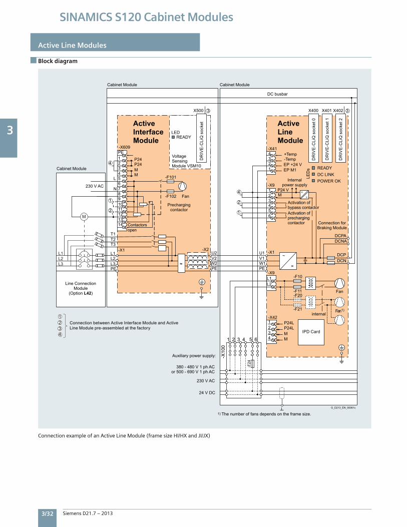
3
3/32 Siemens D21.7 – 2013
SINAMICS S120 Cabinet Modules
Active Line Modules
Block diagram
ConnectionexampleofanActiveLineModule(framesizeHI/HXandJI/JX)
4321
1 2 3 4 5 6
-X10
0
-F24
internal
Internal power supply
1) The number of fans depends on the frame size.
Fan
Fan 1)
24 V DC
230 V AC
380 - 480 V 1 ph ACor 500 - 690 V 1 ph AC
Auxiliary power supply:
G_D213_EN_00061c
DC busbar
Connection forBraking Module
Prechargingcontactor
Contactorsopen
Fan
Activation ofprechargingcontactor
Activation ofbypass contactor
230 V AC
DR
IVE
-CLi
Q s
ocke
t
DR
IVE
-CLi
Q s
ocke
t 0
DR
IVE
-CLi
Q s
ocke
t 1
DR
IVE
-CLi
Q s
ocke
t 2
Connection between Active Interface Module and Active Line Module pre-assembled at the factory
Cabinet ModuleCabinet Module
Cabinet Module
Line Connection Module
(Option L42)
LED
Active Interface Module READY
Active Line Module
Module VSM10
Voltage Sensing
==
3X402X401X400
DCNADCPA
DCNDCP
EP M1+24 VEP
MP24 V
-F21
-F20-F11
-F10
=
~
L2L1
-X1
-X9PEPE
W2V2U2
-X2
W1V1U1
3
1
2
4
X500
1234-X41
654321-X9
-F102
-F101MMP24P24
2
1
4
T3T2T1
PEL3L2L1
-X1
N
L
1413121110987654321PE-X609
≈
DC LINK POWER OK
READY
LED
s
Temp-Temp+
4
21
3P24L P24L
-X42
MM
IPD Card
L3L2L1
M

3
Siemens D21.7 – 2013 3/33
SINAMICS S120 Cabinet Modules
Technical data
Active Line Modules
Line Voltage 380 … 480 V 3 ph. AC Active Line Module
6SL3730-7TE32-1AU3
6SL3730-7TE32-6AU3
6SL3730-7TE33-8AU3
6SL3730-7TE35-0AU3
Rated power
•ForINDC(60Hz,460V) kW 150 180 270 350
•ForINDC(50Hz,400V) kW 132 160 235 300
•ForIHDC(60Hz,460V) kW 132 160 235 300
•ForIHDC(50Hz,400V) kW 115 145 210 270
DC bus current
•RatedcurrentINDC A 235 291 425 549
•BaseloadcurrentI HDC1) A 209 259 378 489
•MaximumcurrentImaxDC A 352 436 637 823
Input current
•RatedcurrentINE A 210 260 380 490
•MaximumcurrentImaxE A 315 390 570 735
Current demand
•24VDCauxiliarypowersupply A 1.27 1.27 1.52 1.52
•230VACauxiliarypowersupply 0.6 0.6 1.2 1.2
•460(400)VAC2) A 0.63 1.13 1.8 1.8
DC bus capacitance
•BasicLineModule F 4,200 5,200 7,800 9,600
•Driveline-up,max. F 41,600 41,600 76,800 76,800
Power loss, max.3)
•At60Hz460V[50Hz400V] kW 4.4[4.3] 5.1[4.9] 7.2[6.9] 9.0[8.7]
Cooling air requirement cfm[m3/s] 1,380[0.65] 1,380[0.65] 2,760[1.3] 2,760[1.3]
Sound pressure level L pA4)
at60[50]HzdB(A) 73[71] 73[71] 74[72] 74[72]
Output cable length, max.5)
•Shielded ft[m] 8,860[2,700] 8,860[2,700] 8,860[2,700] 8,860[2,700]
•Unshielded ft[m] 13,300[4,050] 13,300[4,050] 13,300[4,050] 13,300[4,050]
Enclosure (base design) IP20 IP20 IP20 IP20
Enclosure dimensions
•Width inch[mm] 31.5[800] 31.5[800] 31.5[800] 31.5[800]
•Height 6) inch[mm] 87[2,200] 87[2,200] 87[2,200] 87[2,200]
•Depth inch[mm] 24[600] 24[600] 24[600] 24[600]
Weight, approx. lb[kg] 840[380] 840[380] 1,170[530] 1,170[530]
Frame size (ALM + AIM) FX+FI FX+FI GX+GI GX+GI
1)ThebaseloadcurrentIHDCisthebasisforadutycycleofduration300swithanoverloadof150%xIHDCfor60s,orImaxDCfor5s.2)Thecurrentdemandforthe460(400)VACauxiliarypowersupplyisdrawnfromthelineinputvoltage.3)Thespecifiedpowerlossrepresentsthemaximumvalueat100%utilization.Thevalueislowerundernormaloperatingconditions.4)TotalsoundpressurelevelofActiveInterfaceModuleandActiveLineModulecombined.5)SumoflengthsofallmotorcablesandDCbus.Longercablelengthsforspecificconfigurationsmaybeavailableonrequest..6)Theenclosureheightincreasesby10”(250mm)forNEMA1(IP21)andby16”(400mm)forNEMA1filtered(IP23),IP43andNEMA12ventilated (IP54)enclosure.
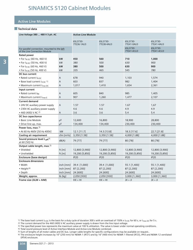
3
3/34 Siemens D21.7 – 2013
SINAMICS S120 Cabinet Modules
Active Line Modules
Technical data
Line Voltage 380 … 480 V 3 ph. AC Active Line Module
6SL3730-7TE36-1AU3
6SL3730-7TE38-4AU3
6SL3730-7TE41-0AU3
6SL3730-7TE41-4AU3
Forparallelconnection,mountedtotheleftoftheLineConnectionModule
6SL3730-7TE41-0CU3
6SL3730-7TE41-4CU3
Rated power
•ForINDC(60Hz,460V) kW 450 560 710 1,000
•ForINDC(50Hz,400V) kW 380 500 630 900
•ForIHDC(60Hz,460V) kW 380 500 630 900
•ForIHDC(50Hz,400V) kW 335 465 545 780
DC bus current
•RatedcurrentINDC A 678 940 1,103 1,574
•BaseloadcurrentI HDC1) A 603 837 982 1,404
•MaximumcurrentImaxDC A 1,017 1,410 1,654 2,361
Input current
•RatedcurrentINE A 605 840 985 1,405
•MaximumcurrentImaxE A 907 1,260 1,477 2,107
Current demand
•24VDCauxiliarypowersupply A 1.57 1.57 1.67 1,67
•230VACauxiliarypowersupply 4.6 4.6 4.9 4.9
•460(400)VAC2) A 3.6 3.6 5.4 5.4
DC bus capacitance
•BasicLineModule F 12,600 16,800 18,900 28,800
•Driveline-up,max. F 134,400 134,400 230,400 230,400
Power loss, max.3)
•At60Hz460V[50Hz400V] kW 12.1[11.7] 14.3[13.8] 18.3[17.6] 22.7[21.8]
Cooling air requirement cfm[m3/s] 3,350[1.58] 3,350[1.58] 4,000[1.88] 4,000[1.88]
Sound pressure level L pA4)
at60[50]HzdB(A) 79[77] 79[77] 80[78] 80[78]
Output cable length, max.5)
•Shielded ft[m] 12,800[3,900] 12,800[3,900] 12,800[3,900] 12,800[3,900]
•Unshielded ft[m] 19,200[5,850] 19,200[5,850] 19,200[5,850] 19,200[5,850]
Enclosure (base design) IP20 IP20 IP20 IP20
Enclosure dimensions
•Width inch[mm] 39.4[1,000] 39.4[1,000] 55.1[1,400] 55.1[1,400]
•Height 6) inch[mm] 87[2,200] 87[2,200] 87[2,200] 87[2,200]
•Depth inch[mm] 24[600] 24[600] 24[600] 24[600]
Weight, approx. lb[kg] 2,050[930] 2,050[930] 3,000[1,360] 3,000[1,360]
Frame size (ALM + AIM) HX+HI HX+HI JX+JI JX+JI
1)ThebaseloadcurrentIHDCisthebasisforadutycycleofduration300swithanoverloadof150%xIHDCfor60s,orImaxDCfor5s.2)Thecurrentdemandforthe460(400)VACauxiliarypowersupplyisdrawnfromthelineinputvoltage.3)Thespecifiedpowerlossrepresentsthemaximumvalueat100%utilization.Thevalueislowerundernormaloperatingconditions.4)TotalsoundpressurelevelofActiveInterfaceModuleandActiveLineModulecombined.5)SumoflengthsofallmotorcablesandDCbus.Longercablelengthsforspecificconfigurationsmaybeavailableonrequest..6)Theenclosureheightincreasesby10”(250mm)forNEMA1(IP21)andby16”(400mm)forNEMA1filtered(IP23),IP43andNEMA12ventilated (IP54)enclosure.
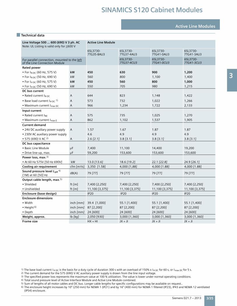
3
Siemens D21.7 – 2013 3/35
SINAMICS S120 Cabinet Modules
Technical data
Active Line Modules
Line Voltage 500 … 600 (690) V 3 ph. AC Note:ULListingisvalidonlyfor<600V
Active Line Module
6SL3730-7TG35-8AU3
6SL3730-7TG37-4AU3
6SL3730-7TG41-0AU3
6SL3730-7TG41-3AU3
Forparallelconnection,mountedtotheleftoftheLineConnectionModule
6SL3730-7TG37-4CU3
6SL3730-7TG41-0CU3
6SL3730-7TG41-3CU3
Rated power
•ForINDC(60Hz,575V) kW 450 630 900 1,200
•ForINDC(50Hz,690V) kW 560 800 1,100 1,400
•ForIHDC(60Hz,575V) kW 450 560 800 1,000
•ForIHDC(50Hz,690V) kW 550 705 980 1,215
DC bus current
•RatedcurrentINDC A 644 823 1,148 1,422
•BaseloadcurrentIHDC1) A 573 732 1,022 1,266
•MaximumcurrentImaxDC A 966 1,234 1,722 2,133
Input current
•RatedcurrentINE A 575 735 1,025 1,270
•MaximumcurrentImaxE A 862 1,102 1,537 1,905
Current demand
•24VDCauxiliarypowersupply A 1.57 1.67 1.87 1.87
•230VACauxiliarypowersupply 4.6 4.9 4.9 4.9
•575(690)VAC2) A 2.6[2.1] 3.8[3.1] 3.8[3.1] 3.8[3.1]
DC bus capacitance
•BasicLineModule F 7,400 11,100 14,400 19,200
•Driveline-up,max. F 59,200 153,600 153,600 153,600
Power loss, max.3)
•At60Hz575V[50Hz690V] kW 13.0[13.6] 18.6[19.2] 22.1[22.8] 24.9[26.1]
Cooling air requirement cfm[m3/s] 3,350[1.58] 4,000[1,88] 4,000[1.88] 4,000[1.88]
Sound pressure level LpA 4)
(1M)at60[50]HzdB(A) 79[77] 79[77] 79[77] 79[77]
Output cable length, max.5)
•Shielded ft[m] 7,400[2,250] 7,400[2,250] 7,400[2,250] 7,400[2,250]
•Unshielded ft[m] 11,100[3,375] 11,100[3,375] 11,100[3,375] 11,100[3,375]
Enclosure (base design) IP20 IP20 IP20 IP20
Enclosure dimensions
•Width inch[mm] 39.4[1,000] 55.1[1,400] 55.1[1,400] 55.1[1,400]
•Height 6) inch[mm] 87[2,200] 87[2,200] 87[2,200] 87[2,200]
•Depth inch[mm] 24[600] 24[600] 24[600] 24[600]
Weight, approx. lb[kg] 2,050[930] 3,000[1,360] 3,000[1,360] 3,000[1,360]
Frame size HX+HI JX+JI JX+JI JX+JI
1)ThebaseloadcurrentIHDCisthebasisforadutycycleofduration300swithanoverloadof150%xI HDCfor60s,orI maxDCfor5s.2)Thecurrentdemandforthe575(690)VACauxiliarypowersupplyisdrawnfromthelineinputvoltage.3)Thespecifiedpowerlossrepresentsthemaximumvalueat100%utilization.Thevalueislowerundernormaloperatingconditions.4)TotalsoundpressurelevelofActiveInterfaceModuleandActiveLineModulecombined.5)SumoflengthsofallmotorcablesandDCbus.Longercablelengthsforspecificconfigurationsmaybeavailableonrequest..6)Theenclosureheightincreasesby10”(250mm)forNEMA1(IP21)andby16”(400mm)forNEMA1filtered(IP23),IP43andNEMA12ventilated (IP54)enclosure.
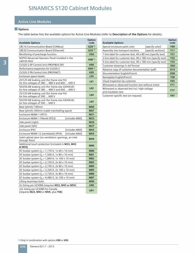
3
3/36 Siemens D21.7 – 2013
SINAMICS S120 Cabinet Modules
Active Line Modules
Options
ThetablebelowliststheavailableoptionsforActiveLineModules(refertoDescription of the Options fordetails).
Available Options Optioncode
CBC10CommunicationBoard(CANbus) G20 1)
CBE20CommunicationBoard(Ethernet) G33 1)
Monitoringofprechargefunction G56
AOP30AdvancedOperatorPanelinstalledinthecabinetdoor K08 1)
CU320-2DPControlUnit(PROFIBUSDP) K90
PerformanceexpansionforCU320-2 K94 1)
CU320-2PNControlUnit(PROFINET) K95
Enclosurespaceheater L55
25/125kWbrakingunit(forframesizeFX)forlinevoltagesof380...480Vand660...690V L61
50/250kWbrakingunit(forframesizeGX/HX/JX)forlinevoltagesof380...480Vand660...690V L62
25/125kWbrakingunit(forframesizeFX)forlinevoltagesof500...600V L64
50/250kWbrakingunit(forframesizeGX/HX/JX)forlinevoltagesof500...600V L65
Base(plinth)100mm M06
Base(plinth)200mm(cablemarshallingspace) M07
EnclosureNEMA1(IP21) M21
EnclosureNEMA1filtered(IP23)[includesM60] M23
Sidepanel(right) M26
Sidepanel(left) M27
EnclosureIP43 [includesM60] M43
EnclosureNEMA12(ventilated)(IP54)[includesM60] M54
Solidcabinetdoor(noventilationopenings,airinletthroughfloor) M59
Additionaltouchprotection[includedinM23, M43 & M54] M60
DCbusbarsystem(Id=1,170A,1x60x10mm) M80
DCbusbarsystem(Id=1,500A,1x80x10mm) M81
DCbusbarsystem(Id=1,840A,1x100x10mm) M82
DCbusbarsystem(Id=2,150A,2x60x10mm) M83
DCbusbarsystem(Id=2,730A,2x80x10mm) M84
DCbusbarsystem(Id=3,320A,2x100x10mm) M85
DCbusbarsystem(Id=3,720A,3x80x10mm) M86
DCbusbarsystem(Id=4,480A,3x100x10mm) M87
Liftingbeam/eyebolts M90
ULlistingperUL508A[requiresM23, M43 or M54] U90
cULlistingperUL508AforCanada[requiresM23, M43 or M54,plusT58] U91
Available Options Optioncode
Specialenclosurepaintcolor[specifycolor] Y09
Assemblyintotransportsections[specifysections] Y11
1-linelabelforcustomertext,40x80mm[specifytext] Y31
2-linelabelforcustomertext,40x180mm[specifytext] Y32
4-linelabelforcustomertext,40x180mm[specifytext] Y33
Customerdrawingsindxfformat D02
Advancecopyofcustomerdocumentation(pdf) D14
DocumentationEnglish/French D58
NameplateEnglish/French T58
VisualInspectionbycustomer F03
Witnessedorobservedfunctiontestwithoutmotor F71
Witnessedorobservedtestincl.high-voltageandinsulationtest
F77
Customerspecifictest(onrequest) F97
1)OnlyincombinationwithoptionsK90orK95.
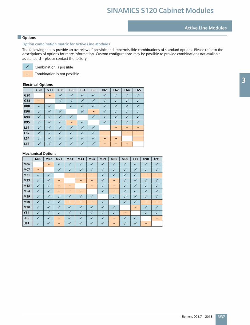
3
Siemens D21.7 – 2013 3/37
SINAMICS S120 Cabinet Modules
Option combination matrix for Active Line Modules
Thefollowingtablesprovideanoverviewofpossibleandimpermissiblecombinationsofstandardoptions.Pleaserefertothedescriptionsofoptionsformoreinformation.Customconfigurationsmaybepossibletoprovidecombinationsnotavailableasstandard–pleasecontactthefactory.
Combinationispossible
–Combinationisnotpossible
Electrical Options
G20 G33 K08 K90 K94 K95 K61 L62 L64 L65
G20 –
G33 –
K08
K90 –
K94
K95 –
L61 – – –
L62 – – –
L64 – –
L65 – – –
Options
Active Line Modules
Mechanical OptionsM06 M07 M21 M23 M43 M54 M59 M60 M90 Y11 U90 U91
M06 –
M07 –
M21 – – – – –
M23 – – – –
M43 – – – –
M54 – – – –
M59
M60 – – – – –
M90 –
Y11 –
U90 – – –
U91 – – –
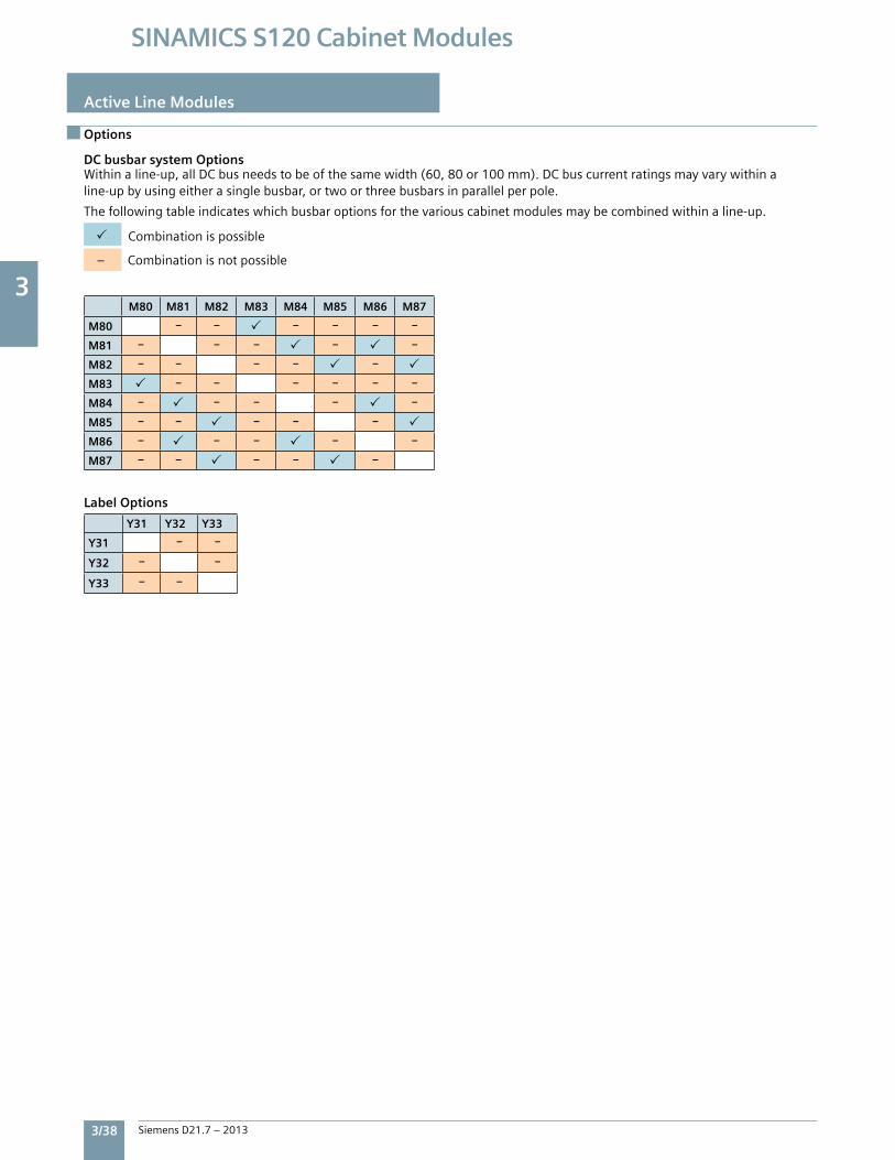
3
3/38 Siemens D21.7 – 2013
SINAMICS S120 Cabinet Modules
Options
Active Line Modules
DC busbar system OptionsWithinaline-up,allDCbusneedstobeofthesamewidth(60,80or100mm).DCbuscurrentratingsmayvarywithinaline-upbyusingeitherasinglebusbar,ortwoorthreebusbarsinparallelperpole.
Thefollowingtableindicateswhichbusbaroptionsforthevariouscabinetmodulesmaybecombinedwithinaline-up.
Combinationispossible
–Combinationisnotpossible
M80 M81 M82 M83 M84 M85 M86 M87
M80 – – – – – –
M81 – – – – –
M82 – – – – –
M83 – – – – – –
M84 – – – – –
M85 – – – – –
M86 – – – – –
M87 – – – – –
Y31 Y32 Y33
Y31 – –
Y32 – –
Y33 – –
Label Options
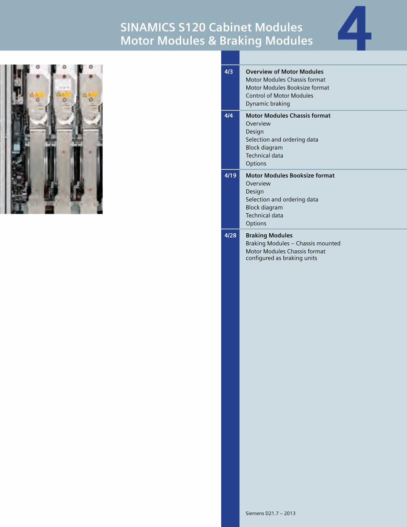
5
SINAMICS S120 Cabinet ModulesMotor Modules & Braking Modules
4/3 Overview of Motor Modules MotorModulesChassisformat MotorModulesBooksizeformat ControlofMotorModules Dynamicbraking
4/4 Motor Modules Chassis format Overview Design Selectionandorderingdata Blockdiagram Technicaldata Options
4/19 Motor Modules Booksize format Overview Design Selectionandorderingdata Blockdiagram Technicaldata Options
4/28 Braking Modules BrakingModules–Chassismounted MotorModulesChassisformat configuredasbrakingunits
4
SiemensD21.7–2013
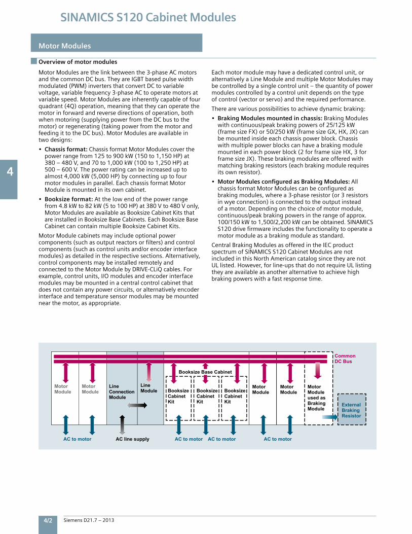
4
4/2 Siemens D21.7 – 2013
SINAMICS S120 Cabinet Modules
Overview of motor modules
Motor Modules are the link between the 3-phase AC motors and the common DC bus. They are IGBT based pulse width modulated (PWM) inverters that convert DC to variable voltage, variable frequency 3-phase AC to operate motors at variable speed. Motor Modules are inherently capable of four quadrant (4Q) operation, meaning that they can operate the motor in forward and reverse directions of operation, both when motoring (supplying power from the DC bus to the motor) or regenerating (taking power from the motor and feeding it to the DC bus). Motor Modules are available in two designs:
• Chassis format: Chassis format Motor Modules cover the power range from 125 to 900 kW (150 to 1,150 HP) at 380 – 480 V, and 70 to 1,000 kW (100 to 1,250 HP) at 500 – 600 V. The power rating can be increased up to almost 4,000 kW (5,000 HP) by connecting up to four motor modules in parallel. Each chassis format Motor Module is mounted in its own cabinet.
• Booksize format: At the low end of the power range from 4.8 kW to 82 kW (5 to 100 HP) at 380 V to 480 V only, Motor Modules are available as Booksize Cabinet Kits that are installed in Booksize Base Cabinets. Each Booksize Base Cabinet can contain multiple Booksize Cabinet Kits.
Motor Module cabinets may include optional power components (such as output reactors or filters) and control components (such as control units and/or encoder interface modules) as detailed in the respective sections. Alternatively, control components may be installed remotely and connected to the Motor Module by DRIVE-CLiQ cables. For example, control units, I/O modules and encoder interface modules may be mounted in a central control cabinet that does not contain any power circuits, or alternatively encoder interface and temperature sensor modules may be mounted near the motor, as appropriate.
Each motor module may have a dedicated control unit, or alternatively a Line Module and multiple Motor Modules may be controlled by a single control unit – the quantity of power modules controlled by a control unit depends on the type of control (vector or servo) and the required performance.
There are various possibilities to achieve dynamic braking:
• Braking Modules mounted in chassis: Braking Modules with continuous/peak braking powers of 25/125 kW (frame size FX) or 50/250 kW (frame size GX, HX, JX) can be mounted inside each chassis power block. Chassis with multiple power blocks can have a braking module mounted in each power block (2 for frame size HX, 3 for frame size JX). These braking modules are offered with matching braking resistors (each braking module requires its own resistor).
• Motor Modules configured as Braking Modules: All chassis format Motor Modules can be configured as braking modules, where a 3-phase resistor (or 3 resistors in wye connection) is connected to the output instead of a motor. Depending on the choice of motor module, continuous/peak braking powers in the range of approx. 100/150 kW to 1,500/2,200 kW can be obtained. SINAMICS S120 drive firmware includes the functionality to operate a motor module as a braking module as standard.
Central Braking Modules as offered in the IEC product spectrum of SINAMICS S120 Cabinet Modules are not included in this North American catalog since they are not UL listed. However, for line-ups that do not require UL listing they are available as another alternative to achieve high braking powers with a fast response time.
Motor Modules
ExternalBraking Resistor
AC to motor
LineModule
Motor Module
Motor Module
LineConnectionModule
Motor Module
Motor ModuleBooksize
CabinetKit
Motor Moduleused asBraking Module
BooksizeCabinetKit
BooksizeCabinetKit
Common DC Bus
AC line supply AC to motor AC to motor AC to motor
Motor Module
Motor Module
Booksize Base Cabinet
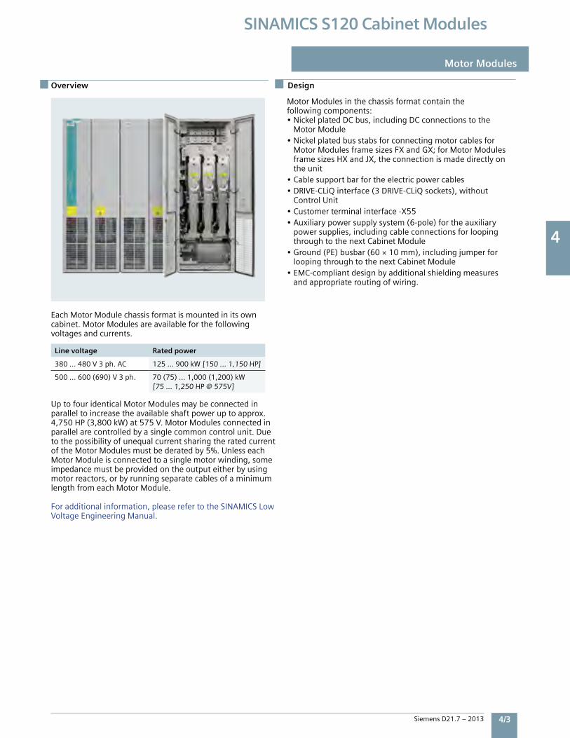
4
Siemens D21.7 – 2013 4/3
SINAMICS S120 Cabinet Modules
Motor Modules
Overview
EachMotorModulechassisformatismountedinitsowncabinet.MotorModulesareavailableforthefollowingvoltagesandcurrents.
Line voltage Rated power
380…480V3ph.AC 125…900kW[150…1,150HP]
500…600(690)V3ph. 70(75)…1,000(1,200)kW[75…1,250HP@575V]
UptofouridenticalMotorModulesmaybeconnectedinparalleltoincreasetheavailableshaftpoweruptoapprox.4,750HP(3,800kW)at575V.MotorModulesconnectedinparallelarecontrolledbyasinglecommoncontrolunit.DuetothepossibilityofunequalcurrentsharingtheratedcurrentoftheMotorModulesmustbederatedby5%.UnlesseachMotorModuleisconnectedtoasinglemotorwinding,someimpedancemustbeprovidedontheoutputeitherbyusingmotorreactors,orbyrunningseparatecablesofaminimumlengthfromeachMotorModule.
Foradditionalinformation,pleaserefertotheSINAMICSLowVoltageEngineeringManual.
MotorModulesinthechassisformatcontainthefollowingcomponents:•NickelplatedDCbus,includingDCconnectionstothe MotorModule•Nickelplatedbusstabsforconnectingmotorcablesfor MotorModulesframesizesFXandGX;forMotorModules framesizesHXandJX,theconnectionismadedirectlyon theunit•Cablesupportbarfortheelectricpowercables•DRIVE-CLiQinterface(3DRIVE-CLiQsockets),without ControlUnit•Customerterminalinterface-X55•Auxiliarypowersupplysystem(6-pole)fortheauxiliary powersupplies,includingcableconnectionsforlooping throughtothenextCabinetModule•Ground(PE)busbar(60×10mm),includingjumperfor loopingthroughtothenextCabinetModule•EMC-compliantdesignbyadditionalshieldingmeasures andappropriateroutingofwiring.
Design
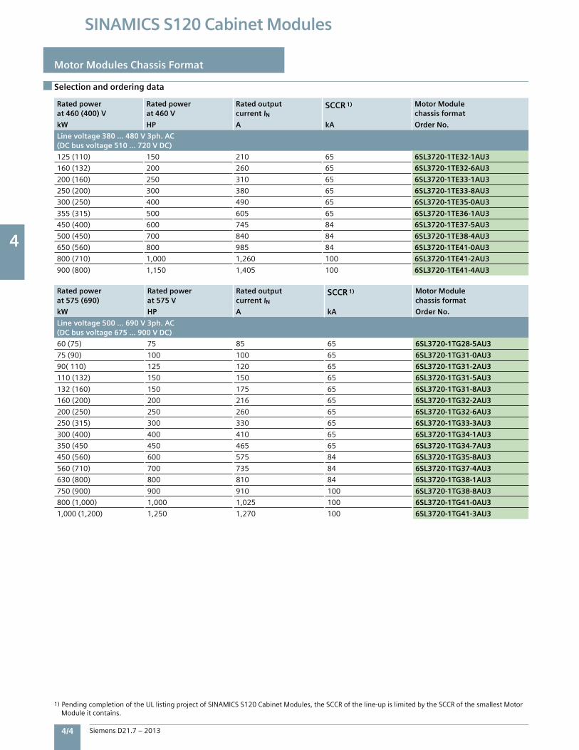
4
4/4 Siemens D21.7 – 2013
SINAMICS S120 Cabinet Modules
Selection and ordering data
Motor Modules Chassis Format
Rated power at 460 (400) V
Rated power at 460 V
Rated output current IN
SCCR 1) Motor Module chassis format
kW HP A kA Order No.
Line voltage 380 … 480 V 3ph. AC(DC bus voltage 510 … 720 V DC)
125(110) 150 210 65 6SL3720-1TE32-1AU3
160(132) 200 260 65 6SL3720-1TE32-6AU3
200(160) 250 310 65 6SL3720-1TE33-1AU3
250(200) 300 380 65 6SL3720-1TE33-8AU3
300(250) 400 490 65 6SL3720-1TE35-0AU3
355(315) 500 605 65 6SL3720-1TE36-1AU3
450(400) 600 745 84 6SL3720-1TE37-5AU3
500(450) 700 840 84 6SL3720-1TE38-4AU3
650(560) 800 985 84 6SL3720-1TE41-0AU3
800(710) 1,000 1,260 100 6SL3720-1TE41-2AU3
900(800) 1,150 1,405 100 6SL3720-1TE41-4AU3
Rated power at 575 (690)
Rated power at 575 V
Rated output current IN
SCCR 1) Motor Module chassis format
kW HP A kA Order No.
Line voltage 500 … 690 V 3ph. AC(DC bus voltage 675 … 900 V DC)
60(75) 75 85 65 6SL3720-1TG28-5AU3
75(90) 100 100 65 6SL3720-1TG31-0AU3
90(110) 125 120 65 6SL3720-1TG31-2AU3
110(132) 150 150 65 6SL3720-1TG31-5AU3
132(160) 150 175 65 6SL3720-1TG31-8AU3
160(200) 200 216 65 6SL3720-1TG32-2AU3
200(250) 250 260 65 6SL3720-1TG32-6AU3
250(315) 300 330 65 6SL3720-1TG33-3AU3
300(400) 400 410 65 6SL3720-1TG34-1AU3
350(450 450 465 65 6SL3720-1TG34-7AU3
450(560) 600 575 84 6SL3720-1TG35-8AU3
560(710) 700 735 84 6SL3720-1TG37-4AU3
630(800) 800 810 84 6SL3720-1TG38-1AU3
750(900) 900 910 100 6SL3720-1TG38-8AU3
800(1,000) 1,000 1,025 100 6SL3720-1TG41-0AU3
1,000(1,200) 1,250 1,270 100 6SL3720-1TG41-3AU3
1)PendingcompletionoftheULlistingprojectofSINAMICSS120CabinetModules,theSCCRoftheline-upislimitedbytheSCCRofthesmallestMotorModuleitcontains.
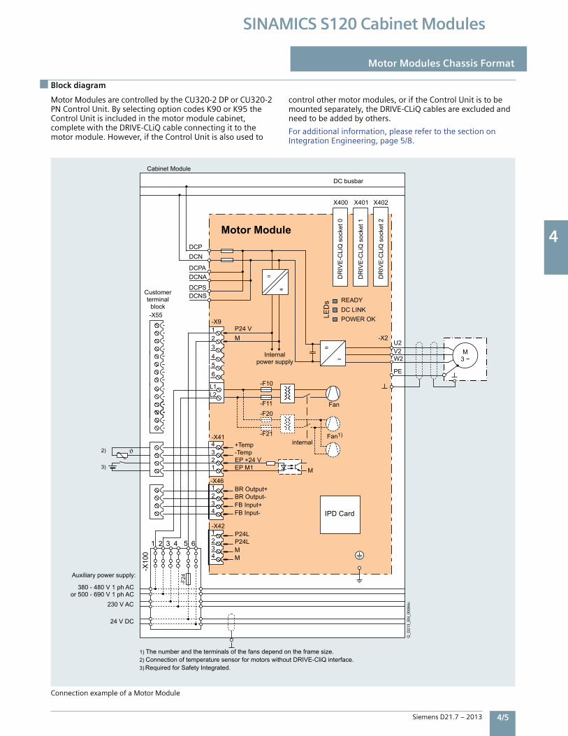
4
Siemens D21.7 – 2013 4/5
SINAMICS S120 Cabinet Modules
Block diagram
Motor Modules Chassis Format
IPD Card
DR
IVE
-CLi
Q s
ocke
t 0
DR
IVE
-CLi
Q s
ocke
t 1
DR
IVE
-CLi
Q s
ocke
t 2
internal
Internal power supply
Fan1)
Fan
24 V DC
230 V AC
380 - 480 V 1 ph ACor 500 - 690 V 1 ph AC
Auxiliary power supply:
DC busbar
Customerterminal
block
2) Connection of temperature sensor for motors without DRIVE-CliQ interface. 1) The number and the terminals of the fans depend on the frame size.
3) Required for Safety Integrated.
G_D
213_
EN
_000
64c
LED
s
-X10
0
=
=
M3 ~
Motor Module
-X55
Cabinet Module
X401X400 X402
EP +24 V EP M1 M
Temp-Temp+
1234-X41
DCNSDCPS
DCNADCPA
DCNDCP
-F21
-F20-F11
-F10
~
=
L2L1
M
P24L P24L
4321-X42
MM
-X46
5 6
3 4
1 2
W2V2
PE
U2 -X2
-X9P24 V
DC LINKPOWER OK
READY
-F24
1 2 3 4 5 6
BR Output+ BR Output-
4321
FB Input+FB Input-
2)
3)
ConnectionexampleofaMotorModule
MotorModulesarecontrolledbytheCU320-2DPorCU320-2PNControlUnit.ByselectingoptioncodesK90orK95theControlUnitisincludedinthemotormodulecabinet,completewiththeDRIVE-CLiQcableconnectingittothemotormodule.However,iftheControlUnitisalsousedto
controlothermotormodules,oriftheControlUnitistobemountedseparately,theDRIVE-CLiQcablesareexcludedandneedtobeaddedbyothers.
Foradditionalinformation,pleaserefertothesectiononIntegrationEngineering,page5/8.

4
4/6 Siemens D21.7 – 2013
SINAMICS S120 Cabinet Modules
Motor Modules Chassis Format
Line voltage 380 … 480 V 3 ph. AC DC bus voltage 510 … 720 V DC
Motor Module chassis format6SL3720-1TE32-1AU3
6SL3720-1TE32-6AU3
6SL3720-1TE33-1AU3
6SL3720-1TE33-8AU3
6SL3720-1TE35-0AU3
6SL3720-1TE36-1AU3
Rated power
• ForIL(60Hz,460V)1)2) kW[HP] 125[150] 160[200] 200[250] 250[300] 300[400] 355[500]•ForIL(50Hz,400V)1) kW 110 132 160 200 250 315•ForIH(60Hz,460V)1)2) kW[HP] 110[125] 132[150] 160[200] 200[250] 250[350] 315[400]
•ForIH(50Hz,400V)1) kW 90 110 132 160 200 250Output current•RatedcurrentIN A 210 260 310 380 490 605
• BaseloadcurrentIL3) A 205 250 302 370 477 590
•BaseloadcurrentIH4) A 178 233 277 340 438 460
•MaximumcurrentImaxA A 307 375 453 555 715 885
DC bus current• RatedcurrentINDCifsuppliedby
- Basic/SmartLineModule A 252 312 372 456 588 726
- ActiveLineModule A 227 281 335 411 529 653
•RatedcurrentILDC3)ifsuppliedby
- Basic/SmartLineModule A 245 304 362 444 573 707
- ActiveLineModule A 221 273 326 400 515 636
•RatedcurrentIHDC4)ifsuppliedby
-Basic/SmartLineModule A 224 277 331 405 523 646
-ActiveLineModule A 202 250 298 365 470 581
Current demand
•24VDCauxiliarypowersupply A 0.8 0.8 0.9 0.9 0.9 1.0
•460(400)VAC A 0.63 1.13 1.8 1.8 1.8 3.6
DC bus capacitance F 4,200 5,200 6,300 7,800 9,600 12,600
Pulse frequency 5)
• Rated kHz 2 2 2 2 2 1.25
• Maximum(withderating) kHz 8 8 8 8 8 7.5
Power loss, max. 6)
• At60Hz460V[50Hz400V] kW 1.94[1.86] 2.6[2.5] 3.1[2.96] 3.8[3.67] 4.5[4.28] 6.3[5.84]
Cooling air requirement cfm[m3/s]
360[0.17] 487[0.23] 763[0.36] 763[0.36] 763[0.36] 1,653[0.78]
Sound pressure level LpA(1m)dB(A) 67 69 69 69 69 72
at60[50]Hz
Technical data
1) RatedpowerinkWisofatypical6-polestandardinductionmotorwithanFLAofILorIHatthelistedvoltageandfrequency.2) RatedpowerinHPisbasedonNECtable430-150.NotethatHP ratings are provided as a guide only,forstandard2,4or6polemotors.Actual motorcurrentsmaybehigher,especiallyformotorswith8ormorepoles.3) ThebaseloadcurrentIListhebasisforadutycycleofdurationof300swithanoverloadof110%for60sor150%for10s.4) ThebaseloadcurrentIHisthebasisforadutycycleofdurationof300swithanoverloadof150%for60sor160%for10s.5) Informationregardingthecorrelationbetweenthepulsefrequencyandmax.outputcurrent/outputfrequencyisprovidedintheSINAMICSLow VoltageEngineeringManual.6) Thespecifiedpowerlossrepresentsthemaximumvalueat100%utilization.Thevalueislowerundernormaloperatingconditions.
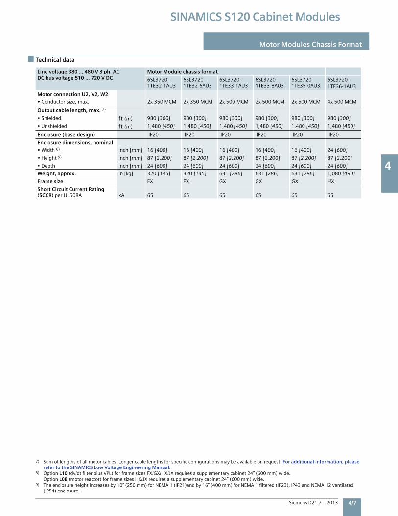
4
Siemens D21.7 – 2013 4/7
SINAMICS S120 Cabinet Modules
Line voltage 380 … 480 V 3 ph. ACDC bus voltage 510 … 720 V DC
Motor Module chassis format
6SL3720-1TE32-1AU3
6SL3720-1TE32-6AU3
6SL3720-1TE33-1AU3
6SL3720-1TE33-8AU3
6SL3720-1TE35-0AU3
6SL3720-1TE36-1AU3
Motor connection U2, V2, W2
• Conductorsize,max. 2x350MCM 2x350MCM 2x500MCM 2x500MCM 2x500MCM 4x500MCM
Output cable length, max.7)
•Shielded ft(m) 980[300] 980[300] 980[300] 980[300] 980[300] 980[300]
•Unshielded ft(m) 1,480[450] 1,480[450] 1,480[450] 1,480[450] 1,480[450] 1,480[450]
Enclosure (base design) IP20 IP20 IP20 IP20 IP20 IP20
Enclosure dimensions, nominal
• Width8) inch[mm] 16[400] 16[400] 16[400] 16[400] 16[400] 24[600]
•Height9) inch[mm] 87[2,200] 87[2,200] 87[2,200] 87[2,200] 87[2,200] 87[2,200]
•Depth inch[mm] 24[600] 24[600] 24[600] 24[600] 24[600] 24[600]
Weight, approx. lb[kg] 320[145] 320[145] 631[286] 631[286] 631[286] 1,080[490]
Frame size FX FX GX GX GX HX
Short Circuit Current Rating (SCCR) perUL508A kA 65 65 65 65 65 65
Line voltage 380 … 480 V 3 ph. AC DC bus voltage 510 … 720 V DC
Motor Module chassis format6SL3720-1TE32-1AU3
6SL3720-1TE32-6AU3
6SL3720-1TE33-1AU3
6SL3720-1TE33-8AU3
6SL3720-1TE35-0AU3
6SL3720-1TE36-1AU3
Rated power
• ForIL(60Hz,460V)1)2) kW[HP] 125[150] 160[200] 200[250] 250[300] 300[400] 355[500]•ForIL(50Hz,400V)1) kW 110 132 160 200 250 315•ForIH(60Hz,460V)1)2) kW[HP] 110[125] 132[150] 160[200] 200[250] 250[350] 315[400]
•ForIH(50Hz,400V)1) kW 90 110 132 160 200 250Output current•RatedcurrentIN A 210 260 310 380 490 605
• BaseloadcurrentIL3) A 205 250 302 370 477 590
•BaseloadcurrentIH4) A 178 233 277 340 438 460
•MaximumcurrentImaxA A 307 375 453 555 715 885
DC bus current• RatedcurrentINDCifsuppliedby
- Basic/SmartLineModule A 252 312 372 456 588 726
- ActiveLineModule A 227 281 335 411 529 653
•RatedcurrentILDC3)ifsuppliedby
- Basic/SmartLineModule A 245 304 362 444 573 707
- ActiveLineModule A 221 273 326 400 515 636
•RatedcurrentIHDC4)ifsuppliedby
-Basic/SmartLineModule A 224 277 331 405 523 646
-ActiveLineModule A 202 250 298 365 470 581
Current demand
•24VDCauxiliarypowersupply A 0.8 0.8 0.9 0.9 0.9 1.0
•460(400)VAC A 0.63 1.13 1.8 1.8 1.8 3.6
DC bus capacitance F 4,200 5,200 6,300 7,800 9,600 12,600
Pulse frequency 5)
• Rated kHz 2 2 2 2 2 1.25
• Maximum(withderating) kHz 8 8 8 8 8 7.5
Power loss, max. 6)
• At60Hz460V[50Hz400V] kW 1.94[1.86] 2.6[2.5] 3.1[2.96] 3.8[3.67] 4.5[4.28] 6.3[5.84]
Cooling air requirement cfm[m3/s]
360[0.17] 487[0.23] 763[0.36] 763[0.36] 763[0.36] 1,653[0.78]
Sound pressure level LpA(1m)dB(A) 67 69 69 69 69 72
at60[50]Hz
Technical data
Motor Modules Chassis Format
7) Sumoflengthsofallmotorcables.Longercablelengthsforspecificconfigurationsmaybeavailableonrequest.For additional information, please refer to the SINAMICS Low Voltage Engineering Manual.8) OptionL10(dv/dtfilterplusVPL)forframesizesFX/GX/HX/JXrequiresasupplementarycabinet24”(600mm)wide. OptionL08(motorreactor)forframesizesHX/JXrequiresasupplementarycabinet24”(600mm)wide.9) Theenclosureheightincreasesby10”(250mm)forNEMA1(IP21)andby16”(400mm)forNEMA1filtered(IP23),IP43andNEMA12ventilated (IP54)enclosure.
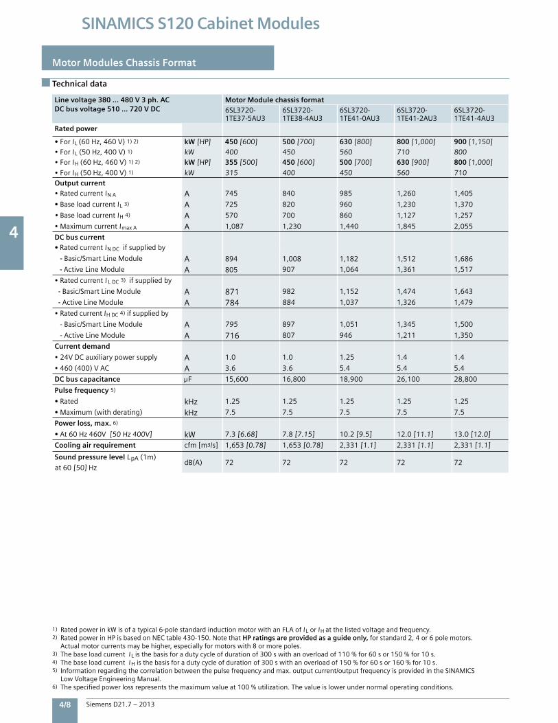
4
4/8 Siemens D21.7 – 2013
SINAMICS S120 Cabinet Modules
Motor Modules Chassis Format
Technical data
Line voltage 380 … 480 V 3 ph. AC DC bus voltage 510 … 720 V DC
Motor Module chassis format6SL3720-1TE37-5AU3
6SL3720-1TE38-4AU3
6SL3720-1TE41-0AU3
6SL3720-1TE41-2AU3
6SL3720-1TE41-4AU3
Rated power
• ForIL(60Hz,460V)1)2) kW[HP] 450 [600] 500 [700] 630 [800] 800 [1,000] 900 [1,150]•ForIL(50Hz,400V)1) kW 400 450 560 710 800•ForIH(60Hz,460V)1)2) kW[HP] 355 [500] 450 [600] 500 [700] 630 [900] 800 [1,000]
•ForIH(50Hz,400V)1) kW 315 400 450 560 710Output current•RatedcurrentINA A 745 840 985 1,260 1,405
• BaseloadcurrentIL3) A 725 820 960 1,230 1,370
•BaseloadcurrentIH4) A 570 700 860 1,127 1,257
•MaximumcurrentImaxA A 1,087 1,230 1,440 1,845 2,055
DC bus current• RatedcurrentINDCifsuppliedby
- Basic/SmartLineModule A 894 1,008 1,182 1,512 1,686
- ActiveLineModule A 805 907 1,064 1,361 1,517
•RatedcurrentI LDC3)ifsuppliedby
- Basic/SmartLineModule A 871 982 1,152 1,474 1,643
- ActiveLineModule A 784 884 1,037 1,326 1,479
•RatedcurrentIHDC4)ifsuppliedby
-Basic/SmartLineModule A 795 897 1,051 1,345 1,500
-ActiveLineModule A 716 807 946 1,211 1,350
Current demand
•24VDCauxiliarypowersupply A 1.0 1.0 1.25 1.4 1.4
•460(400)VAC A 3.6 3.6 5.4 5.4 5.4
DC bus capacitance F 15,600 16,800 18,900 26,100 28,800
Pulse frequency 5)
• Rated kHz 1.25 1.25 1.25 1.25 1.25
• Maximum(withderating) kHz 7.5 7.5 7.5 7.5 7.5
Power loss, max. 6)
• At60Hz460V[50Hz400V] kW 7.3[6.68] 7.8[7.15] 10.2[9.5] 12.0[11.1] 13.0[12.0]
Cooling air requirement cfm[m3/s] 1,653[0.78] 1,653[0.78] 2,331[1.1] 2,331[1.1] 2,331[1.1]
Sound pressure level LpA(1m)dB(A) 72 72 72 72 72
at60[50]Hz
1) RatedpowerinkWisofatypical6-polestandardinductionmotorwithanFLAofI LorIHatthelistedvoltageandfrequency.2) RatedpowerinHPisbasedonNECtable430-150.NotethatHP ratings are provided as a guide only,forstandard2,4or6polemotors. Actualmotorcurrentsmaybehigher,especiallyformotorswith8ormorepoles.3) ThebaseloadcurrentI Listhebasisforadutycycleofdurationof300swithanoverloadof110%for60sor150%for10s.4) ThebaseloadcurrentI Histhebasisforadutycycleofdurationof300swithanoverloadof150%for60sor160%for10s.5) Informationregardingthecorrelationbetweenthepulsefrequencyandmax.outputcurrent/outputfrequencyisprovidedintheSINAMICS LowVoltageEngineeringManual.6) Thespecifiedpowerlossrepresentsthemaximumvalueat100%utilization.Thevalueislowerundernormaloperatingconditions.

4
Siemens D21.7 – 2013 4/9
SINAMICS S120 Cabinet Modules
Technical data
Motor Modules Chassis Format
Line voltage 380 … 480 V 3 ph. AC DC bus voltage 510 … 720 V DC
Motor Module chassis format6SL3720-1TE37-5AU3
6SL3720-1TE38-4AU3
6SL3720-1TE41-0AU3
6SL3720-1TE41-2AU3
6SL3720-1TE41-4AU3
Rated power
• ForIL(60Hz,460V)1)2) kW[HP] 450 [600] 500 [700] 630 [800] 800 [1,000] 900 [1,150]•ForIL(50Hz,400V)1) kW 400 450 560 710 800•ForIH(60Hz,460V)1)2) kW[HP] 355 [500] 450 [600] 500 [700] 630 [900] 800 [1,000]
•ForIH(50Hz,400V)1) kW 315 400 450 560 710Output current•RatedcurrentINA A 745 840 985 1,260 1,405
• BaseloadcurrentIL3) A 725 820 960 1,230 1,370
•BaseloadcurrentIH4) A 570 700 860 1,127 1,257
•MaximumcurrentImaxA A 1,087 1,230 1,440 1,845 2,055
DC bus current• RatedcurrentINDCifsuppliedby
- Basic/SmartLineModule A 894 1,008 1,182 1,512 1,686
- ActiveLineModule A 805 907 1,064 1,361 1,517
•RatedcurrentI LDC3)ifsuppliedby
- Basic/SmartLineModule A 871 982 1,152 1,474 1,643
- ActiveLineModule A 784 884 1,037 1,326 1,479
•RatedcurrentIHDC4)ifsuppliedby
-Basic/SmartLineModule A 795 897 1,051 1,345 1,500
-ActiveLineModule A 716 807 946 1,211 1,350
Current demand
•24VDCauxiliarypowersupply A 1.0 1.0 1.25 1.4 1.4
•460(400)VAC A 3.6 3.6 5.4 5.4 5.4
DC bus capacitance F 15,600 16,800 18,900 26,100 28,800
Pulse frequency 5)
• Rated kHz 1.25 1.25 1.25 1.25 1.25
• Maximum(withderating) kHz 7.5 7.5 7.5 7.5 7.5
Power loss, max. 6)
• At60Hz460V[50Hz400V] kW 7.3[6.68] 7.8[7.15] 10.2[9.5] 12.0[11.1] 13.0[12.0]
Cooling air requirement cfm[m3/s] 1,653[0.78] 1,653[0.78] 2,331[1.1] 2,331[1.1] 2,331[1.1]
Sound pressure level LpA(1m)dB(A) 72 72 72 72 72
at60[50]Hz
Line voltage 380 … 480 V 3 ph. ACDC bus voltage 510 … 720 V DC
Motor Module chassis format
6SL3720-1TE37-5AU3
6SL3720-1TE38-4AU3
6SL3720-1TE41-0AU3
6SL3720-1TE41-2AU3
6SL3720-1TE41-4AU3
Motor connection U2, V2, W2
• Conductorsize,max. 4x500MCM 4x500MCM 6x500MCM 6x500MCM 6x500MCM
Output cable length, max.7)
•Shielded ft(m) 980[300] 980[300] 980[300] 980[300] 980[300]
•Unshielded ft(m) 1,480[450] 1,480[450] 1,480[450] 1,480[450] 1,480[450]
Enclosure (base design) IP20 IP20 IP20 IP20 IP20
Enclosure dimensions, nominal
• Width8) inch[mm] 24[600] 24[600] 31.5[800] 31.5[800] 31.5[800]
•Height9) inch[mm] 87[2,200] 87[2,200] 87[2,200] 87[2,200] 87[2,200]
•Depth inch[mm] 24[600] 24[600] 24[600] 24[600] 24[600]
Weight, approx. lb[kg] 1,080[490] 1,080[490] 1,543[700] 1,543[700] 1,543[700]
Frame size HX HX JX JX JX
Short Circuit Current Rating(SCCR) perUL508A kA 84 84 84 100 100
7) Sumoflengthsofallmotorcables.Longercablelengthsforspecificconfigurationsmaybeavailableonrequest.For additional information, please refer to the SINAMICS Low Voltage Engineering Manual.8) OptionL10(dv/dtfilterplusVPL)forframesizesFX/GX/HX/JXrequiresasupplementarycabinet24”(600mm)wide. OptionL08(motorreactor)forframesizesHX/JXrequiresasupplementarycabinet24”(600mm)wide.9) Theenclosureheightincreasesby10”(250mm)forNEMA1(IP21)andby16”(400mm)forNEMA1filtered(IP23),IP43andNEMA12ventilated (IP54)enclosure.
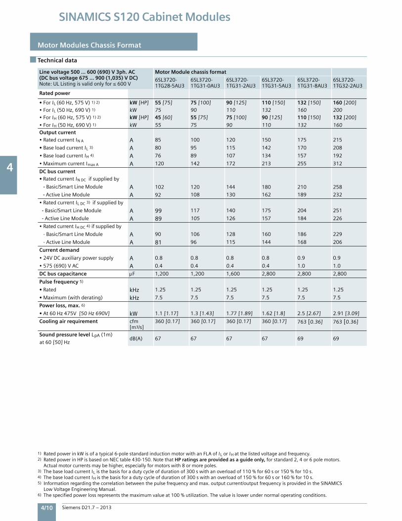
4
4/10 Siemens D21.7 – 2013
SINAMICS S120 Cabinet Modules
Motor Modules Chassis Format
Technical data
Line voltage 500 … 600 (690) V 3ph. AC(DC bus voltage 675 … 900 (1,035) V DC)Note:ULListingisvalidonlyfor≤600V
Motor Module chassis format
6SL3720-1TG28-5AU3
6SL3720-1TG31-0AU3
6SL3720-1TG31-2AU3
6SL3720-1TG31-5AU3
6SL3720-1TG31-8AU3
6SL3720-1TG32-2AU3
Rated power
• ForIL(60Hz,575V)1)2) kW[HP] 55 [75] 75 [100] 90 [125] 110 [150] 132 [150] 160 [200]•ForIL(50Hz,690V)1) kW 75 90 110 132 160 200•ForIH(60Hz,575V)1)2) kW[HP] 45 [60] 55 [75] 75 [100] 90 [125] 110 [150] 132 [200]
•ForIH(50Hz,690V)1) kW 55 75 90 110 132 160Output current•RatedcurrentINA A 85 100 120 150 175 215
• BaseloadcurrentIL3) A 80 95 115 142 170 208
•BaseloadcurrentIH4) A 76 89 107 134 157 192
•MaximumcurrentImaxA A 120 142 172 213 255 312
DC bus current• RatedcurrentINDCifsuppliedby
- Basic/SmartLineModule A 102 120 144 180 210 258
- ActiveLineModule A 92 108 130 162 189 232
•RatedcurrentILDC3)ifsuppliedby
- Basic/SmartLineModule A 99 117 140 175 204 251
- ActiveLineModule A 89 105 126 157 184 226
•RatedcurrentIHDC4)ifsuppliedby
-Basic/SmartLineModule A 90 106 128 160 186 229
-ActiveLineModule A 81 96 115 144 168 206
Current demand
•24VDCauxiliarypowersupply A 0.8 0.8 0.8 0.8 0.9 0.9
•575(690)VAC A 0.4 0.4 0.4 0.4 1.0 1.0
DC bus capacitance F 1,200 1,200 1,600 2,800 2,800 2,800
Pulse frequency 5)
• Rated kHz 1.25 1.25 1.25 1.25 1.25 1.25
• Maximum(withderating) kHz 7.5 7.5 7.5 7.5 7.5 7.5
Power loss, max. 6)
• At60Hz475V[50Hz690V] kW 1.1[1.17] 1.3[1.43] 1.77[1.89] 1.62[1.8] 2.5[2.67] 2.91[3.09]
Cooling air requirement cfm[m3/s]
360[0.17] 360[0.17] 360[0.17] 360[0.17] 763[0.36] 763[0.36]
Sound pressure level LpA(1m)dB(A) 67 67 67 67 69 69
at60[50]Hz
1)RatedpowerinkWisofatypical6-polestandardinductionmotorwithanFLAofI LorIHatthelistedvoltageandfrequency.2) RatedpowerinHPisbasedonNECtable430-150.NotethatHP ratings are provided as a guide only,forstandard2,4or6polemotors. Actualmotorcurrentsmaybehigher,especiallyformotorswith8ormorepoles.3) ThebaseloadcurrentI Listhebasisforadutycycleofdurationof300swithanoverloadof110%for60sor150%for10s.4) ThebaseloadcurrentI Histhebasisforadutycycleofdurationof300swithanoverloadof150%for60sor160%for10s.5) Informationregardingthecorrelationbetweenthepulsefrequencyandmax.outputcurrent/outputfrequencyisprovidedintheSINAMICS LowVoltageEngineeringManual.6)Thespecifiedpowerlossrepresentsthemaximumvalueat100%utilization.Thevalueislowerundernormaloperatingconditions.

4
Siemens D21.7 – 2013 4/11
SINAMICS S120 Cabinet Modules
Technical data
Motor Modules Chassis Format
Line voltage 500 … 600 (690) V 3ph. AC(DC bus voltage 675 … 900 (1,035) V DC)Note:ULListingisvalidonlyfor≤600V
Motor Module chassis format
6SL3720-1TG28-5AU3
6SL3720-1TG31-0AU3
6SL3720-1TG31-2AU3
6SL3720-1TG31-5AU3
6SL3720-1TG31-8AU3
6SL3720-1TG32-2AU3
Rated power
• ForIL(60Hz,575V)1)2) kW[HP] 55 [75] 75 [100] 90 [125] 110 [150] 132 [150] 160 [200]•ForIL(50Hz,690V)1) kW 75 90 110 132 160 200•ForIH(60Hz,575V)1)2) kW[HP] 45 [60] 55 [75] 75 [100] 90 [125] 110 [150] 132 [200]
•ForIH(50Hz,690V)1) kW 55 75 90 110 132 160Output current•RatedcurrentINA A 85 100 120 150 175 215
• BaseloadcurrentIL3) A 80 95 115 142 170 208
•BaseloadcurrentIH4) A 76 89 107 134 157 192
•MaximumcurrentImaxA A 120 142 172 213 255 312
DC bus current• RatedcurrentINDCifsuppliedby
- Basic/SmartLineModule A 102 120 144 180 210 258
- ActiveLineModule A 92 108 130 162 189 232
•RatedcurrentILDC3)ifsuppliedby
- Basic/SmartLineModule A 99 117 140 175 204 251
- ActiveLineModule A 89 105 126 157 184 226
•RatedcurrentIHDC4)ifsuppliedby
-Basic/SmartLineModule A 90 106 128 160 186 229
-ActiveLineModule A 81 96 115 144 168 206
Current demand
•24VDCauxiliarypowersupply A 0.8 0.8 0.8 0.8 0.9 0.9
•575(690)VAC A 0.4 0.4 0.4 0.4 1.0 1.0
DC bus capacitance F 1,200 1,200 1,600 2,800 2,800 2,800
Pulse frequency 5)
• Rated kHz 1.25 1.25 1.25 1.25 1.25 1.25
• Maximum(withderating) kHz 7.5 7.5 7.5 7.5 7.5 7.5
Power loss, max. 6)
• At60Hz475V[50Hz690V] kW 1.1[1.17] 1.3[1.43] 1.77[1.89] 1.62[1.8] 2.5[2.67] 2.91[3.09]
Cooling air requirement cfm[m3/s]
360[0.17] 360[0.17] 360[0.17] 360[0.17] 763[0.36] 763[0.36]
Sound pressure level LpA(1m)dB(A) 67 67 67 67 69 69
at60[50]Hz
Line voltage 500 … 600 (690) V 3ph. AC(DC bus voltage 675 … 900 (1,035) V DC)Note:ULListingisvalidonlyfor≤600V
Motor Module chassis format
6SL3720-1TG28-5AU3
6SL3720-1TG31-0AU3
6SL3720-1TG31-2AU3
6SL3720-1TG31-5AU3
6SL3720-1TG31-8AU3
6SL3720-1TG32-2AU3
Motor connection U2, V2, W2
• Conductorsize,max. 2x350MCM 2x350MCM 2x350MCM 2x350MCM 2x500MCM 2x500MCM
Output cable length, max.7)
•Shielded ft(m) 980[300] 980[300] 980[300] 980[300] 980[300] 980[300]
•Unshielded ft(m) 1,480[450] 1,480[450] 1,480[450] 1,480[450] 1,480[450] 1,480[450]
Enclosure (base design) IP20 IP20 IP20 IP20 IP20 IP20
Enclosure dimensions, nominal
• Width8) inch[mm] 16[400] 16[400] 16[400] 16[400] 16[400] 16[400]
•Height9) inch[mm] 87[2,200] 87[2,200] 87[2,200] 87[2,200] 87[2,200] 87[2,200]
•Depth inch[mm] 24[600] 24[600] 24[600] 24[600] 24[600] 24[600]
Weight, approx. lb[kg] 320[145] 320[145] 320[145] 320[145] 631[286] 631[286]
Frame size FX FX FX FX GX GX
Short Circuit Current Rating (SCCR) perUL508A kA 65 65 65 65 65 65
7) Sumoflengthsofallmotorcables.Longercablelengthsforspecificconfigurationsmaybeavailableonrequest.For additional information, please refer to the SINAMICS Low Voltage Engineering Manual.8) OptionL10(dv/dtfilterplusVPL)forframesizesFX/GX/HX/JXrequiresasupplementarycabinet24”(600mm)wide. OptionL08(motorreactor)forframesizesHX/JXrequiresasupplementarycabinet24”(600mm)wide.9) Theenclosureheightincreasesby10”(250mm)forNEMA1(IP21)andby16”(400mm)forNEMA1filtered(IP23),IP43andNEMA12ventilated (IP54)enclosure.
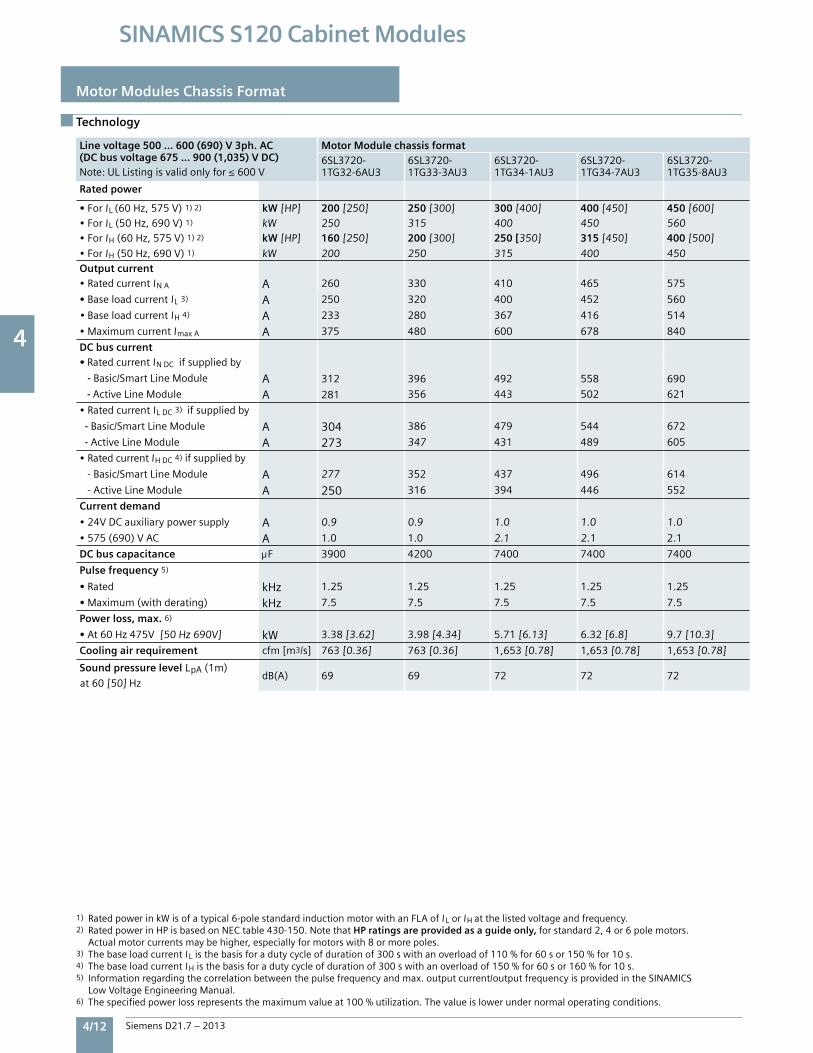
4
4/12 Siemens D21.7 – 2013
SINAMICS S120 Cabinet Modules
Motor Modules Chassis Format
Technology
Line voltage 500 … 600 (690) V 3ph. AC(DC bus voltage 675 … 900 (1,035) V DC)Note:ULListingisvalidonlyfor≤600V
Motor Module chassis format6SL3720-1TG32-6AU3
6SL3720-1TG33-3AU3
6SL3720-1TG34-1AU3
6SL3720-1TG34-7AU3
6SL3720-1TG35-8AU3
Rated power
• ForIL(60Hz,575V)1)2) kW[HP] 200 [250] 250 [300] 300 [400] 400[450] 450 [600]•ForIL(50Hz,690V)1) kW 250 315 400 450 560•ForIH(60Hz,575V)1)2) kW[HP] 160 [250] 200 [300] 250 [350] 315 [450] 400 [500]
•ForIH(50Hz,690V)1) kW 200 250 315 400 450Output current•RatedcurrentINA A 260 330 410 465 575
• BaseloadcurrentIL3) A 250 320 400 452 560
•BaseloadcurrentIH4) A 233 280 367 416 514
•MaximumcurrentImaxA A 375 480 600 678 840
DC bus current• RatedcurrentINDCifsuppliedby
- Basic/SmartLineModule A 312 396 492 558 690
- ActiveLineModule A 281 356 443 502 621
•RatedcurrentILDC3)ifsuppliedby
- Basic/SmartLineModule A 304 386 479 544 672
- ActiveLineModule A 273 347 431 489 605
•RatedcurrentIHDC4)ifsuppliedby
-Basic/SmartLineModule A 277 352 437 496 614
-ActiveLineModule A 250 316 394 446 552
Current demand
•24VDCauxiliarypowersupply A 0.9 0.9 1.0 1.0 1.0
•575(690)VAC A 1.0 1.0 2.1 2.1 2.1
DC bus capacitance F 3900 4200 7400 7400 7400
Pulse frequency 5)
• Rated kHz 1.25 1.25 1.25 1.25 1.25
• Maximum(withderating) kHz 7.5 7.5 7.5 7.5 7.5
Power loss, max. 6)
• At60Hz475V[50Hz690V] kW 3.38[3.62] 3.98[4.34] 5.71[6.13] 6.32[6.8] 9.7[10.3]
Cooling air requirement cfm[m3/s] 763[0.36] 763[0.36] 1,653[0.78] 1,653[0.78] 1,653[0.78]
Sound pressure level LpA(1m)dB(A) 69 69 72 72 72
at60[50]Hz
1) RatedpowerinkWisofatypical6-polestandardinductionmotorwithanFLAofI LorIHatthelistedvoltageandfrequency.2) RatedpowerinHPisbasedonNECtable430-150.NotethatHP ratings are provided as a guide only,forstandard2,4or6polemotors. Actualmotorcurrentsmaybehigher,especiallyformotorswith8ormorepoles.3) ThebaseloadcurrentI Listhebasisforadutycycleofdurationof300swithanoverloadof110%for60sor150%for10s.4) ThebaseloadcurrentI Histhebasisforadutycycleofdurationof300swithanoverloadof150%for60sor160%for10s.5) Informationregardingthecorrelationbetweenthepulsefrequencyandmax.outputcurrent/outputfrequencyisprovidedintheSINAMICS LowVoltageEngineeringManual.6) Thespecifiedpowerlossrepresentsthemaximumvalueat100%utilization.Thevalueislowerundernormaloperatingconditions.
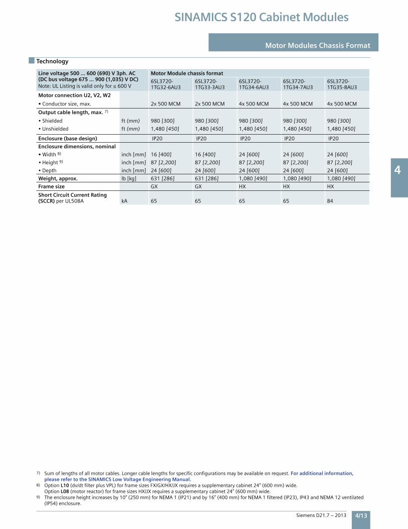
4
Siemens D21.7 – 2013 4/13
SINAMICS S120 Cabinet Modules
Motor Modules Chassis Format
Technology
Line voltage 500 … 600 (690) V 3ph. AC(DC bus voltage 675 … 900 (1,035) V DC)Note:ULListingisvalidonlyfor≤600V
Motor Module chassis format6SL3720-1TG32-6AU3
6SL3720-1TG33-3AU3
6SL3720-1TG34-1AU3
6SL3720-1TG34-7AU3
6SL3720-1TG35-8AU3
Rated power
• ForIL(60Hz,575V)1)2) kW[HP] 200 [250] 250 [300] 300 [400] 400[450] 450 [600]•ForIL(50Hz,690V)1) kW 250 315 400 450 560•ForIH(60Hz,575V)1)2) kW[HP] 160 [250] 200 [300] 250 [350] 315 [450] 400 [500]
•ForIH(50Hz,690V)1) kW 200 250 315 400 450Output current•RatedcurrentINA A 260 330 410 465 575
• BaseloadcurrentIL3) A 250 320 400 452 560
•BaseloadcurrentIH4) A 233 280 367 416 514
•MaximumcurrentImaxA A 375 480 600 678 840
DC bus current• RatedcurrentINDCifsuppliedby
- Basic/SmartLineModule A 312 396 492 558 690
- ActiveLineModule A 281 356 443 502 621
•RatedcurrentILDC3)ifsuppliedby
- Basic/SmartLineModule A 304 386 479 544 672
- ActiveLineModule A 273 347 431 489 605
•RatedcurrentIHDC4)ifsuppliedby
-Basic/SmartLineModule A 277 352 437 496 614
-ActiveLineModule A 250 316 394 446 552
Current demand
•24VDCauxiliarypowersupply A 0.9 0.9 1.0 1.0 1.0
•575(690)VAC A 1.0 1.0 2.1 2.1 2.1
DC bus capacitance F 3900 4200 7400 7400 7400
Pulse frequency 5)
• Rated kHz 1.25 1.25 1.25 1.25 1.25
• Maximum(withderating) kHz 7.5 7.5 7.5 7.5 7.5
Power loss, max. 6)
• At60Hz475V[50Hz690V] kW 3.38[3.62] 3.98[4.34] 5.71[6.13] 6.32[6.8] 9.7[10.3]
Cooling air requirement cfm[m3/s] 763[0.36] 763[0.36] 1,653[0.78] 1,653[0.78] 1,653[0.78]
Sound pressure level LpA(1m)dB(A) 69 69 72 72 72
at60[50]Hz
Line voltage 500 … 600 (690) V 3ph. AC(DC bus voltage 675 … 900 (1,035) V DC)Note:ULListingisvalidonlyfor≤600V
Motor Module chassis format
6SL3720-1TG32-6AU3
6SL3720-1TG33-3AU3
6SL3720-1TG34-6AU3
6SL3720-1TG34-7AU3
6SL3720-1TG35-8AU3
Motor connection U2, V2, W2
• Conductorsize,max. 2x500MCM 2x500MCM 4x500MCM 4x500MCM 4x500MCM
Output cable length, max.7)
•Shielded ft(mm) 980[300] 980[300] 980[300] 980[300] 980[300]
•Unshielded ft(mm) 1,480[450] 1,480[450] 1,480[450] 1,480[450] 1,480[450]
Enclosure (base design) IP20 IP20 IP20 IP20 IP20
Enclosure dimensions, nominal
• Width8) inch[mm] 16[400] 16[400] 24[600] 24[600] 24[600]
•Height9) inch[mm] 87[2,200] 87[2,200] 87[2,200] 87[2,200] 87[2,200]
•Depth inch[mm] 24[600] 24[600] 24[600] 24[600] 24[600]
Weight, approx. lb[kg] 631[286] 631[286] 1,080[490] 1,080[490] 1,080[490]
Frame size GX GX HX HX HX
Short Circuit Current Rating(SCCR) perUL508A kA 65 65 65 65 84
7) Sumoflengthsofallmotorcables.Longercablelengthsforspecificconfigurationsmaybeavailableonrequest.For additional information, please refer to the SINAMICS Low Voltage Engineering Manual.8) OptionL10(dv/dtfilterplusVPL)forframesizesFX/GX/HX/JXrequiresasupplementarycabinet24”(600mm)wide. OptionL08(motorreactor)forframesizesHX/JXrequiresasupplementarycabinet24”(600mm)wide.9) Theenclosureheightincreasesby10”(250mm)forNEMA1(IP21)andby16”(400mm)forNEMA1filtered(IP23),IP43andNEMA12ventilated (IP54)enclosure.

4
4/14 Siemens D21.7 – 2013
SINAMICS S120 Cabinet Modules
Motor Modules Chassis Format
Technology
Line voltage 500 … 600 (690) V 3ph. AC(DC bus voltage 675 … 900 (1,035) V DC)Note:ULListingisvalidonlyfor≤600V
Motor Module chassis format6SL3720-1TG37-4AU3
6SL3720-1TG38-1AU3
6SL3720-1TG38-8AU3
6SL3720-1TG41-0AU3
6SL3720-1TG41-3AU3
Rated power
• ForIL(60Hz,575V)1)2) kW[HP] 560 [700] 630 [800] 710 [900] 800 [1,000] 1,000 [1,250]•ForIL(50Hz,690V)1) kW 710 800 900 1,000 1,200•ForIH(60Hz,575V)1)2) kW[HP] 500 [600] 560 [700] 630 [800] 710 [900] 800 [1,000]
•ForIH(50Hz,690V)1) kW 630 710 800 900 1,000Output current•RatedcurrentINA A 735 810 910 1,025 1,270
• BaseloadcurrentIL3) A 710 790 880 1,000 1,230
•BaseloadcurrentIH4) A 657 724 814 917 1,136
•MaximumcurrentImaxA A 1,065 1,185 1,320 1,500 1,845
DC bus current• RatedcurrentINDCifsuppliedby
- Basic/SmartLineModule A 882 972 1,092 1,230 1,524
- ActiveLineModule A 794 875 983 1,107 1,372
•RatedcurrentILDC3)ifsuppliedby
- Basic/SmartLineModule A 859 947 1,064 1,199 1,485
- ActiveLineModule A 774 853 958 1,079 1,337
•RatedcurrentIHDC4)ifsuppliedby
-Basic/SmartLineModule A 784 865 971 1,094 1,356
-ActiveLineModule A 706 778 874 985 1,221
Current demand
•24VDCauxiliarypowersupply A 1.25 1.25 1.4 1.4 1.4
•575(690)VAC A 3.1 3.1 3.1 3.1 3.1
DC bus capacitance F 11,100 11,100 14,400 14,400 19,200
Pulse frequency 5)
• Rated kHz 1.25 1.25 1.25 1.25 1.25
• Maximum(withderating) kHz 7.5 7.5 7.5 7.5 7.5
Power loss, max. 6)
• At60Hz475V[50Hz690V] kW 10[10.9] 10.5[11.5] 10.6[11.7] 12[13.2] 14.2[16]
Cooling air requirement cfm[m3/s] 3,123[1.474] 3,123[1.474] 3,123[1.474] 3,123[1.474] 3,123[1.474]
Sound pressure level LpA(1m)dB(A) 72 72 72 72 72
at60[50]Hz
1) RatedpowerinkWisofatypical6-polestandardinductionmotorwithanFLAofI LorIHatthelistedvoltageandfrequency.2) RatedpowerinHPisbasedonNECtable430-150.NotethatHP ratings are provided as a guide only,forstandard2,4or6polemotors. Actualmotorcurrentsmaybehigher,especiallyformotorswith8ormorepoles.3) ThebaseloadcurrentI Listhebasisforadutycycleofdurationof300swithanoverloadof110%for60sor150%for10s.4) ThebaseloadcurrentI Histhebasisforadutycycleofdurationof300swithanoverloadof150%for60sor160%for10s.5) Informationregardingthecorrelationbetweenthepulsefrequencyandmax.outputcurrent/outputfrequencyisprovidedintheSINAMICS LowVoltageEngineeringManual.6) Thespecifiedpowerlossrepresentsthemaximumvalueat100%utilization.Thevalueislowerundernormaloperatingconditions.

4
Siemens D21.7 – 2013 4/15
SINAMICS S120 Cabinet Modules
Technology
Motor Modules Chassis Format
Line voltage 500 … 600 (690) V 3ph. AC(DC bus voltage 675 … 900 (1,035) V DC)Note:ULListingisvalidonlyfor≤600V
Motor Module chassis format6SL3720-1TG37-4AU3
6SL3720-1TG38-1AU3
6SL3720-1TG38-8AU3
6SL3720-1TG41-0AU3
6SL3720-1TG41-3AU3
Rated power
• ForIL(60Hz,575V)1)2) kW[HP] 560 [700] 630 [800] 710 [900] 800 [1,000] 1,000 [1,250]•ForIL(50Hz,690V)1) kW 710 800 900 1,000 1,200•ForIH(60Hz,575V)1)2) kW[HP] 500 [600] 560 [700] 630 [800] 710 [900] 800 [1,000]
•ForIH(50Hz,690V)1) kW 630 710 800 900 1,000Output current•RatedcurrentINA A 735 810 910 1,025 1,270
• BaseloadcurrentIL3) A 710 790 880 1,000 1,230
•BaseloadcurrentIH4) A 657 724 814 917 1,136
•MaximumcurrentImaxA A 1,065 1,185 1,320 1,500 1,845
DC bus current• RatedcurrentINDCifsuppliedby
- Basic/SmartLineModule A 882 972 1,092 1,230 1,524
- ActiveLineModule A 794 875 983 1,107 1,372
•RatedcurrentILDC3)ifsuppliedby
- Basic/SmartLineModule A 859 947 1,064 1,199 1,485
- ActiveLineModule A 774 853 958 1,079 1,337
•RatedcurrentIHDC4)ifsuppliedby
-Basic/SmartLineModule A 784 865 971 1,094 1,356
-ActiveLineModule A 706 778 874 985 1,221
Current demand
•24VDCauxiliarypowersupply A 1.25 1.25 1.4 1.4 1.4
•575(690)VAC A 3.1 3.1 3.1 3.1 3.1
DC bus capacitance F 11,100 11,100 14,400 14,400 19,200
Pulse frequency 5)
• Rated kHz 1.25 1.25 1.25 1.25 1.25
• Maximum(withderating) kHz 7.5 7.5 7.5 7.5 7.5
Power loss, max. 6)
• At60Hz475V[50Hz690V] kW 10[10.9] 10.5[11.5] 10.6[11.7] 12[13.2] 14.2[16]
Cooling air requirement cfm[m3/s] 3,123[1.474] 3,123[1.474] 3,123[1.474] 3,123[1.474] 3,123[1.474]
Sound pressure level LpA(1m)dB(A) 72 72 72 72 72
at60[50]Hz
Line voltage 500 … 600 (690) V 3ph. AC(DC bus voltage 675 … 900 (1,035) V DC)Note:ULListingisvalidonlyfor≤600V
Motor Module chassis format
6SL3720-1TG37-4AU3
6SL3720-1TG38-1AU3
6SL3720-1TG38-8AU3
6SL3720-1TG41-0AU3
6SL3720-1TG41-3AU3
Motor connection U2, V2, W2
• Conductorsize,max. 6x500MCM 6x500MCM 6x500MCM 6x500MCM 6x500MCM
Output cable length, max.7)
•Shielded ft(m) 980[300] 980[300] 980[300] 980[300] 980[300]
•Unshielded ft(m) 1,480[450] 1,480[450] 1,480[450] 1,480[450] 1,480[450]
Enclosure (base design) IP20 IP20 IP20 IP20 IP20
Enclosure dimensions, nominal
• Width8) inch[mm] 31.5[800] 31.5[800] 31.5[800] 31.5[800] 31.5[800]
•Height9) inch[mm] 87[2,200] 87[2,200] 87[2,200] 87[2,200] 87[2,200]
•Depth inch[mm] 24[600] 24[600] 24[600] 24[600] 24[600]
Weight, approx. lb[kg] 1,543[700] 1,543[700] 1,543[700] 1,543[700] 1,543[700]
Frame size JX JX JX JX JX
Short Circuit Current Rating(SCCR) perUL508A kA 84 84 100 100 100
7) Sumoflengthsofallmotorcables.Longercablelengthsforspecificconfigurationsmaybeavailableonrequest.For additional information, please refer to the SINAMICS Low Voltage Engineering Manual.8) OptionL10(dv/dtfilterplusVPL)forframesizesFX/GX/HX/JXrequiresasupplementarycabinet24”(600mm)wide. OptionL08(motorreactor)forframesizesHX/JXrequiresasupplementarycabinet24”(600mm)wide.9) Theenclosureheightincreasesby10”(250mm)forNEMA1(IP21)andby16”(400mm)forNEMA1filtered(IP23),IP43andNEMA12ventilated (IP54)enclosure.
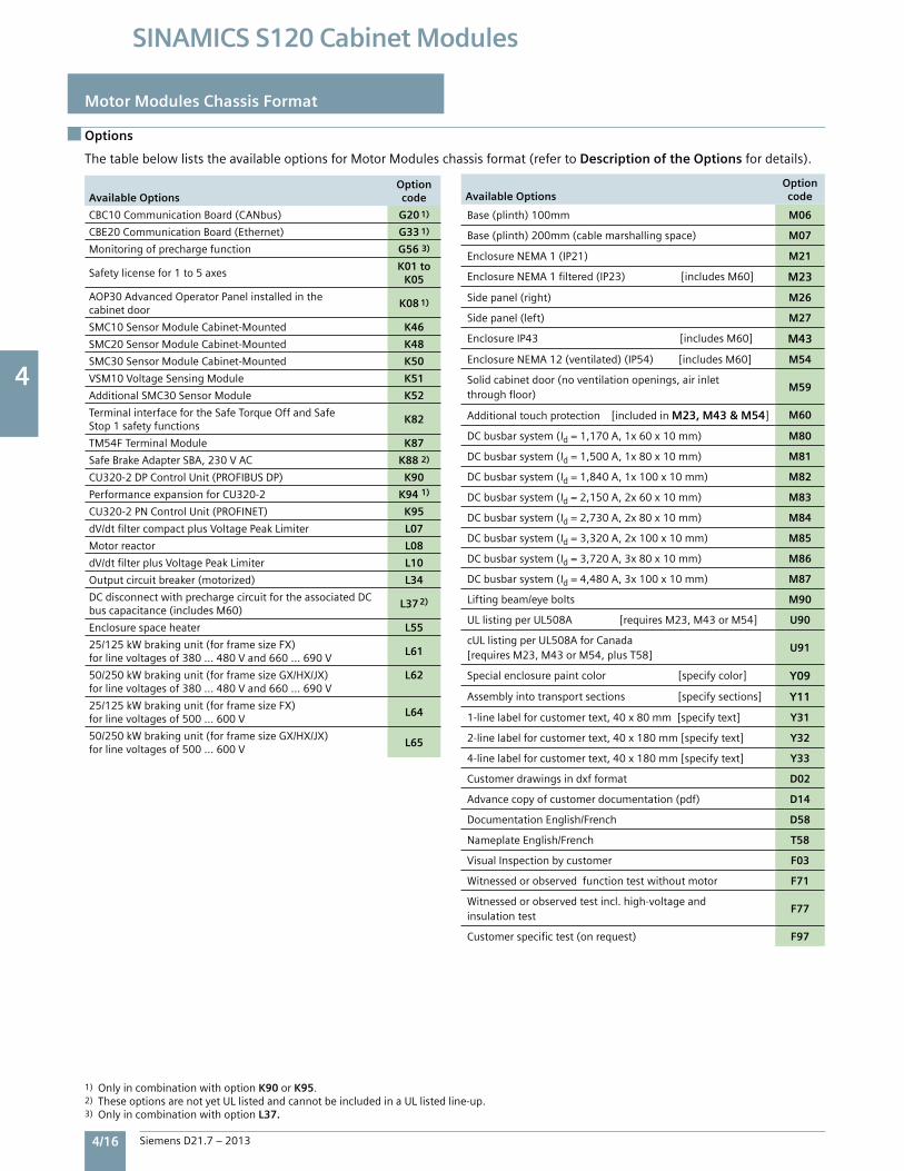
4
4/16 Siemens D21.7 – 2013
SINAMICS S120 Cabinet Modules
Motor Modules Chassis Format
Options
The table below lists the available options for Motor Modules chassis format (refer to Description of the Options for details).
Available Options Optioncode
CBC10 Communication Board (CANbus) G20 1)
CBE20 Communication Board (Ethernet) G33 1)
Monitoring of precharge function G56 3)
Safety license for 1 to 5 axes K01 to
K05
AOP30 Advanced Operator Panel installed in thecabinet door
K08 1)
SMC10 Sensor Module Cabinet-Mounted K46
SMC20 Sensor Module Cabinet-Mounted K48
SMC30 Sensor Module Cabinet-Mounted K50
VSM10 Voltage Sensing Module K51
Additional SMC30 Sensor Module K52
Terminal interface for the Safe Torque Off and Safe Stop 1 safety functions
K82
TM54F Terminal Module K87
Safe Brake Adapter SBA, 230 V AC K88 2)
CU320-2 DP Control Unit (PROFIBUS DP) K90
Performance expansion for CU320-2 K94 1)
CU320-2 PN Control Unit (PROFINET) K95
dV/dt filter compact plus Voltage Peak Limiter L07
Motor reactor L08
dV/dt filter plus Voltage Peak Limiter L10
Output circuit breaker (motorized) L34
DC disconnect with precharge circuit for the associated DC bus capacitance (includes M60)
L37 2)
Enclosure space heater L55
25/125 kW braking unit (for frame size FX) for line voltages of 380 ... 480 V and 660 ... 690 V
L61
50/250 kW braking unit (for frame size GX/HX/JX) for line voltages of 380 ... 480 V and 660 ... 690 V
L62
25/125 kW braking unit (for frame size FX) for line voltages of 500 ... 600 V
L64
50/250 kW braking unit (for frame size GX/HX/JX) for line voltages of 500 ... 600 V
L65
Available Options Optioncode
Base (plinth) 100mm M06
Base (plinth) 200mm (cable marshalling space) M07
Enclosure NEMA 1 (IP21) M21
Enclosure NEMA 1 filtered (IP23) [includes M60] M23
Side panel (right) M26
Side panel (left) M27
Enclosure IP43 [includes M60] M43
Enclosure NEMA 12 (ventilated) (IP54) [includes M60] M54
Solid cabinet door (no ventilation openings, air inlet through floor)
M59
Additional touch protection [included in M23, M43 & M54] M60
DC busbar system (Id = 1,170 A, 1x 60 x 10 mm) M80
DC busbar system (Id = 1,500 A, 1x 80 x 10 mm) M81
DC busbar system (Id = 1,840 A, 1x 100 x 10 mm) M82
DC busbar system (Id = 2,150 A, 2x 60 x 10 mm) M83
DC busbar system (Id = 2,730 A, 2x 80 x 10 mm) M84
DC busbar system (Id = 3,320 A, 2x 100 x 10 mm) M85
DC busbar system (Id = 3,720 A, 3x 80 x 10 mm) M86
DC busbar system (Id = 4,480 A, 3x 100 x 10 mm) M87
Lifting beam/eye bolts M90
UL listing per UL508A [requires M23, M43 or M54] U90
cUL listing per UL508A for Canada [requires M23, M43 or M54, plus T58]
U91
Special enclosure paint color [specify color] Y09
Assembly into transport sections [specify sections] Y11
1-line label for customer text, 40 x 80 mm [specify text] Y31
2-line label for customer text, 40 x 180 mm [specify text] Y32
4-line label for customer text, 40 x 180 mm [specify text] Y33
Customer drawings in dxf format D02
Advance copy of customer documentation (pdf) D14
Documentation English/French D58
Nameplate English/French T58
Visual Inspection by customer F03
Witnessed or observed function test without motor F71
Witnessed or observed test incl. high-voltage and insulation test
F77
Customer specific test (on request) F97
1) Only in combination with option K90 or K95.2) These options are not yet UL listed and cannot be included in a UL listed line-up.3) Only in combination with option L37.
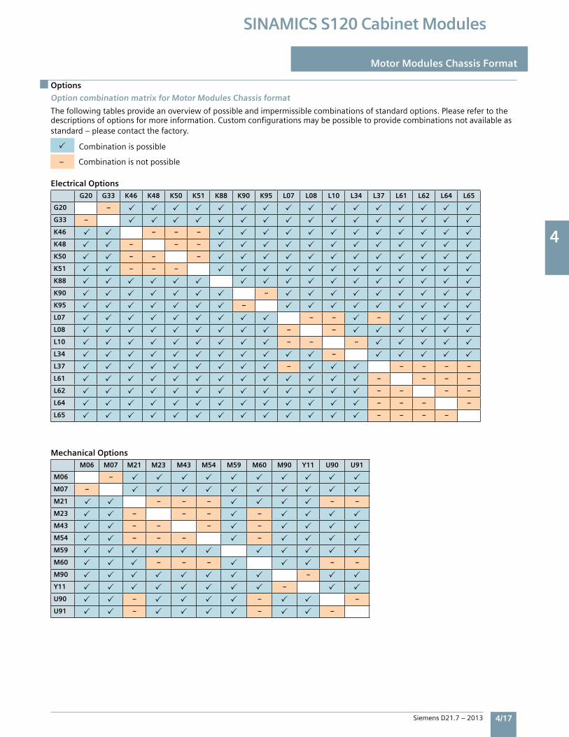
4
Siemens D21.7 – 2013 4/17
SINAMICS S120 Cabinet Modules
Options
Motor Modules Chassis Format
Option combination matrix for Motor Modules Chassis format
Thefollowingtablesprovideanoverviewofpossibleandimpermissiblecombinationsofstandardoptions.Pleaserefertothedescriptionsofoptionsformoreinformation.Customconfigurationsmaybepossibletoprovidecombinationsnotavailableasstandard–pleasecontactthefactory.
Combinationispossible
–Combinationisnotpossible
Electrical OptionsG20 G33 K46 K48 K50 K51 K88 K90 K95 L07 L08 L10 L34 L37 L61 L62 L64 L65
G20 –
G33 –
K46 – – –
K48 – – –
K50 – – –
K51 – – –
K88
K90 –
K95 –
L07 – – –
L08 – –
L10 – – –
L34 –
L37 – – – – –
L61 – – – –
L62 – – – –
L64 – – – –
L65 – – – –
Mechanical OptionsM06 M07 M21 M23 M43 M54 M59 M60 M90 Y11 U90 U91
M06 –
M07 –
M21 – – – – –
M23 – – – –
M43 – – – –
M54 – – – –
M59
M60 – – – – –
M90 –
Y11 –
U90 – – –
U91 – – –
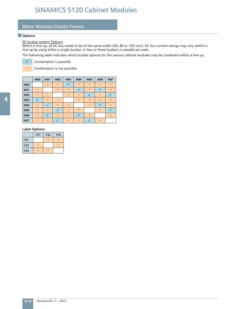
4
4/18 Siemens D21.7 – 2013
SINAMICS S120 Cabinet Modules
Motor Modules Chassis Format
Options
DCbusbarsystemOptionsWithinaline-up,allDCbusneedstobeofthesamewidth(60,80or100mm).DCbuscurrentratingsmayvarywithinaline-upbyusingeitherasinglebusbar,ortwoorthreebusbarsinparallelperpole.
Thefollowingtableindicateswhichbusbaroptionsforthevariouscabinetmodulesmaybecombinedwithinaline-up.
Combinationispossible
–Combinationisnotpossible
M80 M81 M82 M83 M84 M85 M86 M87
M80 – – – – – –
M81 – – – – –
M82 – – – – –
M83 – – – – – –
M84 – – – – –
M85 – – – – –
M86 – – – – –
M87 – – – – –
Y31 Y32 Y33
Y31 – –
Y32 – –
Y33 – –
Label Options
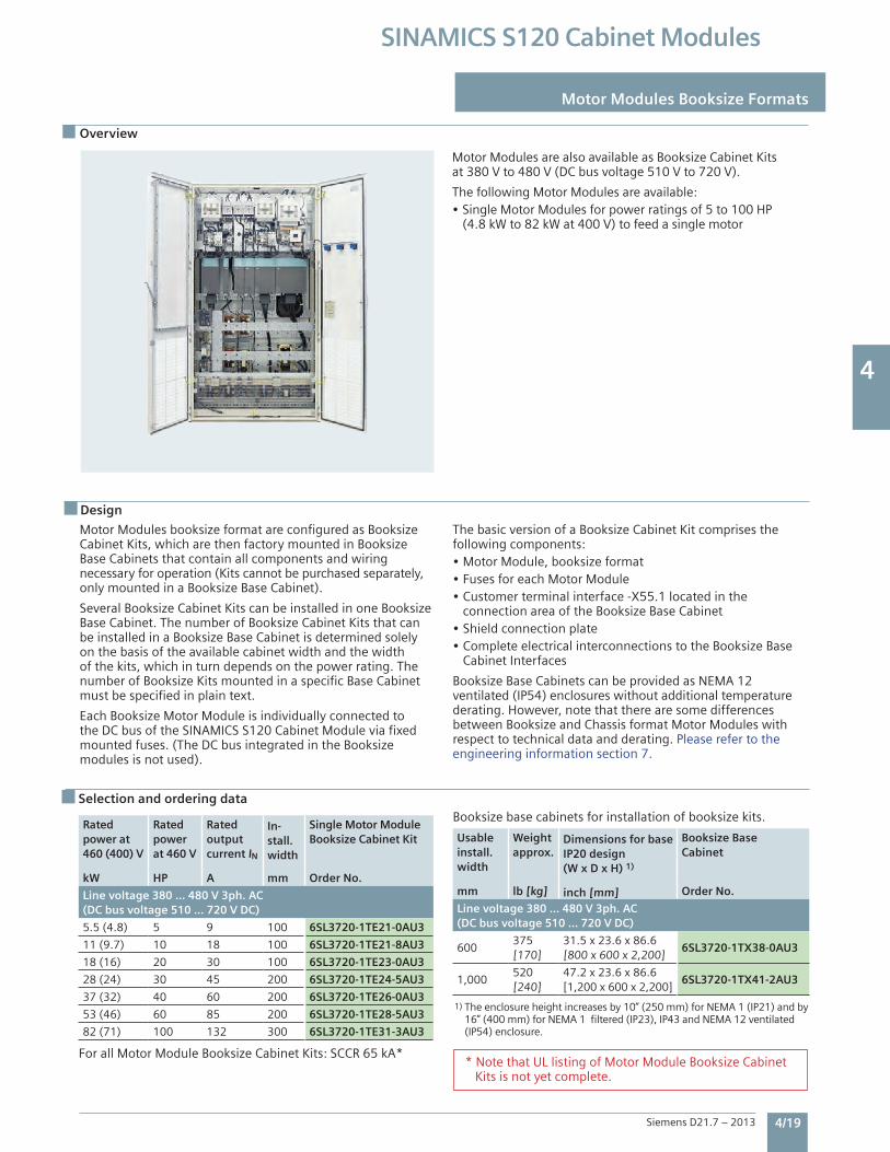
4
Siemens D21.7 – 2013 4/19
SINAMICS S120 Cabinet Modules
Design
Motor Modules booksize format are configured as Booksize Cabinet Kits, which are then factory mounted in Booksize Base Cabinets that contain all components and wiringnecessary for operation (Kits cannot be purchased separately, only mounted in a Booksize Base Cabinet).
Several Booksize Cabinet Kits can be installed in one Booksize Base Cabinet. The number of Booksize Cabinet Kits that can be installed in a Booksize Base Cabinet is determined solely on the basis of the available cabinet width and the width of the kits, which in turn depends on the power rating. The number of Booksize Kits mounted in a specific Base Cabinet must be specified in plain text.
Each Booksize Motor Module is individually connected to the DC bus of the SINAMICS S120 Cabinet Module via fixed mounted fuses. (The DC bus integrated in the Booksize modules is not used).
The basic version of a Booksize Cabinet Kit comprises the following components:• Motor Module, booksize format• Fuses for each Motor Module• Customer terminal interface -X55.1 located in the connection area of the Booksize Base Cabinet• Shield connection plate• Complete electrical interconnections to the Booksize Base Cabinet Interfaces
Booksize Base Cabinets can be provided as NEMA 12 ventilated (IP54) enclosures without additional temperature derating. However, note that there are some differences between Booksize and Chassis format Motor Modules with respect to technical data and derating. Please refer to the engineering information section 7.
Motor Modules are also available as Booksize Cabinet Kits at 380 V to 480 V (DC bus voltage 510 V to 720 V).
The following Motor Modules are available:• Single Motor Modules for power ratings of 5 to 100 HP (4.8 kW to 82 kW at 400 V) to feed a single motor
Selection and ordering dataBooksize base cabinets for installation of booksize kits.
Usable install. width
Weightapprox.
Dimensions for base IP20 design (W x D x H) 1)
Booksize BaseCabinet
mm lb [kg] inch [mm] Order No.
Line voltage 380 … 480 V 3ph. AC(DC bus voltage 510 … 720 V DC)
600375 [170]
31.5 x 23.6 x 86.6[800 x 600 x 2,200]
6SL3720-1TX38-0AU3
1,000520 [240]
47.2 x 23.6 x 86.6[1,200 x 600 x 2,200]
6SL3720-1TX41-2AU3
Rated power at 460 (400) V
Rated power at 460 V
Rated output current IN
In-stall.width
Single Motor Module Booksize Cabinet Kit
kW HP A mm Order No.
Line voltage 380 … 480 V 3ph. AC(DC bus voltage 510 … 720 V DC)
5.5 (4.8) 5 9 100 6SL3720-1TE21-0AU3
11 (9.7) 10 18 100 6SL3720-1TE21-8AU3
18 (16) 20 30 100 6SL3720-1TE23-0AU3
28 (24) 30 45 200 6SL3720-1TE24-5AU3
37 (32) 40 60 200 6SL3720-1TE26-0AU3
53 (46) 60 85 200 6SL3720-1TE28-5AU3
82 (71) 100 132 300 6SL3720-1TE31-3AU3
For all Motor Module Booksize Cabinet Kits: SCCR 65 kA*
Overview
Motor Modules Booksize Formats
* Note that UL listing of Motor Module Booksize Cabinet Kits is not yet complete.
1) The enclosure height increases by 10” (250 mm) for NEMA 1 (IP21) and by 16” (400 mm) for NEMA 1 filtered (IP23), IP43 and NEMA 12 ventilated (IP54) enclosure.
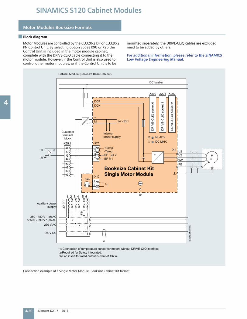
4
4/20 Siemens D21.7 – 2013
SINAMICS S120 Cabinet Modules
Motor Modules are controlled by the CU320-2 DP or CU320-2 PN Control Unit. By selecting option codes K90 or K95 the Control Unit is included in the motor module cabinet, complete with the DRIVE-CLiQ cable connecting it to the motor module. However, if the Control Unit is also used to control other motor modules, or if the Control Unit is to be
mounted separately, the DRIVE-CLiQ cables are excluded need to be added by others.
For additional information, please refer to the SINAMICS Low Voltage Engineering Manual.
Motor Modules Booksize Formats
Block diagram
Connection example of a Single Motor Module, Booksize Cabinet Kit format
~
=
1 2 3 4 5 6
-X10
0
-F24
Internal power supply
24 V DC
230 V AC
380 - 480 V 1 ph ACor 500 - 690 V 1 ph AC
Auxiliary powersupply:
Customerterminal
block
DC busbar
Fan
DR
IVE
-CLi
Q s
ocke
t 0
DR
IVE
-CLi
Q s
ocke
t 1
DR
IVE
-CLi
Q s
ocke
t 2
1) Connection of temperature sensor for motors without DRIVE-CliQ interface.2) Required for Safety Integrated.3) Fan insert for rated output current of 132 A.
G_D
213_
EN
_000
63c
24 V DC
M3 ~
Cabinet Module (Booksize Base Cabinet)
Booksize Cabinet Kit Single Motor Module
21
~
W2V2
PE
U2
-X55.1
-X12
EP M1+24 VEP
Temp-Temp+
4321
-X21
M+
DCNDCP
-X1
X201X200 X202
=
DC LINK READY
LED
s1)
2)
3)
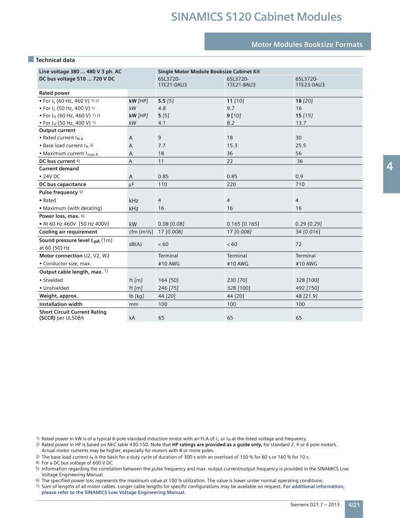
4
Siemens D21.7 – 2013 4/21
SINAMICS S120 Cabinet Modules
Motor Modules Booksize Formats
Technical data
Line voltage 380 … 480 V 3 ph. ACDC bus voltage 510 … 720 V DC
Single Motor Module Booksize Cabinet Kit 6SL3720-1TE21-0AU3
6SL3720-1TE21-8AU3
6SL3720-1TE23-0AU3
Rated power
• ForIL(60Hz,460V)1)2) kW[HP] 5.5 [5] 11 [10] 18 [20]•ForIL(50Hz,400V)1) kW 4.8 9.7 16•ForIH(60Hz,460V)1)2) kW[HP] 5 [5] 9 [10] 15 [15]•ForIH(50Hz,400V)1) kW 4.1 8.2 13.7Output current•RatedcurrentINA A 9 18 30
•BaseloadcurrentIH3) A 7.7 15.3 25.5
•MaximumcurrentImaxA A 18 36 56
DC bus current 4) A 11 22 36Current demand
•24VDC A 0.85 0.85 0.9
DC bus capacitance F 110 220 710
Pulse frequency 5)
• Rated kHz 4 4 4
• Maximum(withderating) kHz 16 16 16
Power loss, max. 6)
• At60Hz460V[50Hz400V] kW 0.08[0.08] 0.165[0.165] 0.29[0.29]
Cooling air requirement cfm[m3/s] 17[0.008] 17[0.008] 34[0.016]
Sound pressure level LpA(1m)dB(A) <60 <60 72
at60[50]Hz
Motor connectionU2,V2,W2 Terminal Terminal Terminal
•Conductorsize,max. #10AWG #10AWG #10AWG
Output cable length, max. 7)
•Shielded ft[m] 164[50] 230[70] 328[100]
•Unshielded ft[m] 246[75] 328[100] 492[150]
Weight, approx. lb[kg] 44[20] 44[20] 48[21.9]
Installation width mm 100 100 100
Short Circuit Current Rating(SCCR) perUL508A kA 65 65 65
1) RatedpowerinkWisofatypical6-polestandardinductionmotorwithanFLAofI LorIHatthelistedvoltageandfrequency.2) RatedpowerinHPisbasedonNECtable430-150.NotethatHP ratings are provided as a guide only,forstandard2,4or6polemotors. Actualmotorcurrentsmaybehigher,especiallyformotorswith8ormorepoles.3) ThebaseloadcurrentIHisthebasisforadutycycleofdurationof300swithanoverloadof150%for60sor160%for10s.4) ForaDCbusvoltageof600VDC.5) Informationregardingthecorrelationbetweenthepulsefrequencyandmax.outputcurrent/outputfrequencyisprovidedintheSINAMICSLow VoltageEngineeringManual.6) Thespecifiedpowerlossrepresentsthemaximumvalueat100%utilization.Thevalueislowerundernormaloperatingconditions.7) Sumoflengthsofallmotorcables.Longercablelengthsforspecificconfigurationsmaybeavailableonrequest.For additional information, please refer to the SINAMICS Low Voltage Engineering Manual.
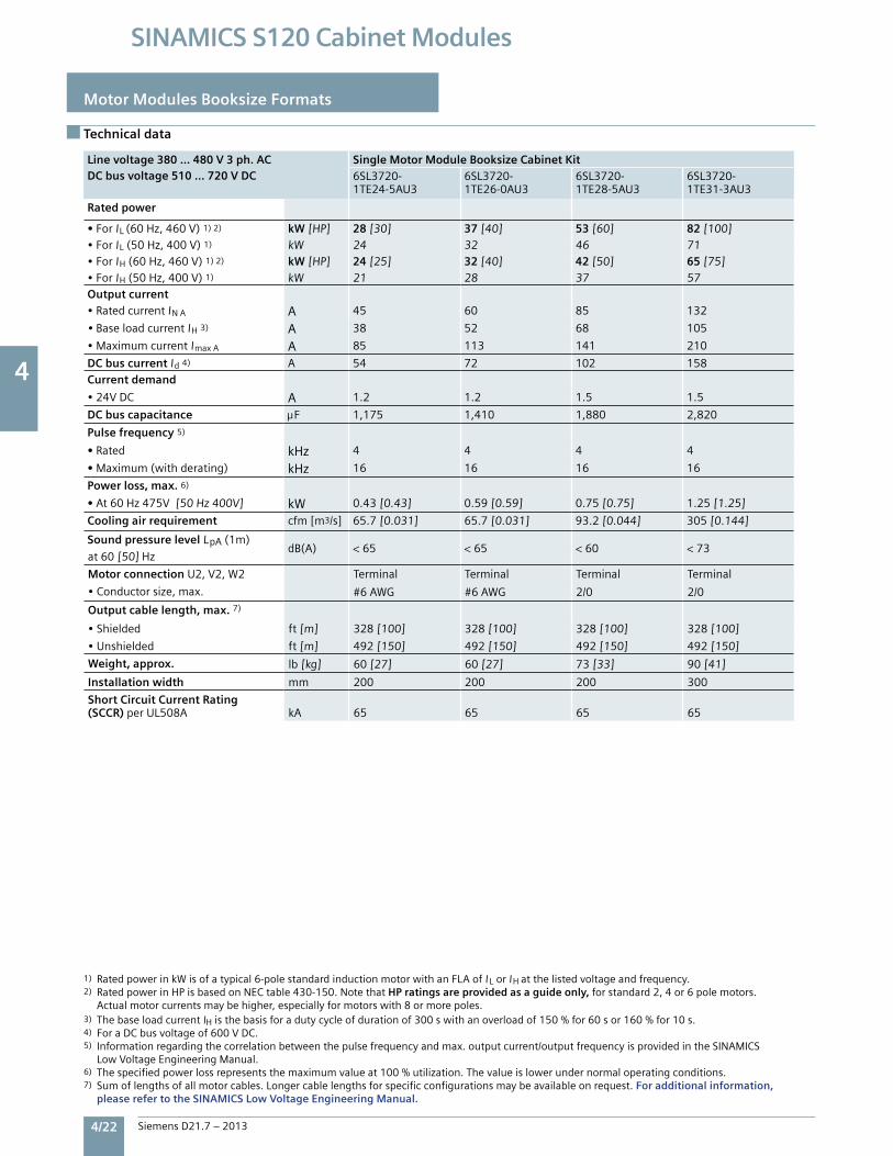
4
4/22 Siemens D21.7 – 2013
SINAMICS S120 Cabinet Modules
Technical data
Motor Modules Booksize Formats
Line voltage 380 … 480 V 3 ph. ACDC bus voltage 510 … 720 V DC
Single Motor Module Booksize Cabinet Kit 6SL3720-1TE24-5AU3
6SL3720-1TE26-0AU3
6SL3720-1TE28-5AU3
6SL3720-1TE31-3AU3
Rated power
• ForIL(60Hz,460V)1)2) kW[HP] 28 [30] 37 [40] 53 [60] 82 [100]•ForIL(50Hz,400V)1) kW 24 32 46 71•ForIH(60Hz,460V)1)2) kW[HP] 24 [25] 32 [40] 42 [50] 65 [75]•ForIH(50Hz,400V)1) kW 21 28 37 57Output current•RatedcurrentINA A 45 60 85 132
•BaseloadcurrentIH3) A 38 52 68 105
•MaximumcurrentImaxA A 85 113 141 210
DC bus current Id4) A 54 72 102 158Current demand
•24VDC A 1.2 1.2 1.5 1.5
DC bus capacitance F 1,175 1,410 1,880 2,820
Pulse frequency 5)
• Rated kHz 4 4 4 4
• Maximum(withderating) kHz 16 16 16 16
Power loss, max. 6)
• At60Hz475V[50Hz400V] kW 0.43[0.43] 0.59[0.59] 0.75[0.75] 1.25[1.25]
Cooling air requirement cfm[m3/s] 65.7[0.031] 65.7[0.031] 93.2[0.044] 305[0.144]
Sound pressure level LpA(1m)dB(A) <65 <65 <60 <73
at60[50]Hz
Motor connectionU2,V2,W2 Terminal Terminal Terminal Terminal
•Conductorsize,max. #6AWG #6AWG 2/0 2/0
Output cable length, max. 7)
•Shielded ft[m] 328[100] 328[100] 328[100] 328[100]
•Unshielded ft[m] 492[150] 492[150] 492[150] 492[150]
Weight, approx. lb[kg] 60[27] 60[27] 73[33] 90[41]
Installation width mm 200 200 200 300
Short Circuit Current Rating(SCCR) perUL508A kA 65 65 65 65
1) RatedpowerinkWisofatypical6-polestandardinductionmotorwithanFLAofI LorIHatthelistedvoltageandfrequency.2) RatedpowerinHPisbasedonNECtable430-150.NotethatHP ratings are provided as a guide only,forstandard2,4or6polemotors. Actualmotorcurrentsmaybehigher,especiallyformotorswith8ormorepoles.3) ThebaseloadcurrentIHisthebasisforadutycycleofdurationof300swithanoverloadof150%for60sor160%for10s.4) ForaDCbusvoltageof600VDC.5) Informationregardingthecorrelationbetweenthepulsefrequencyandmax.outputcurrent/outputfrequencyisprovidedintheSINAMICS LowVoltageEngineeringManual.6) Thespecifiedpowerlossrepresentsthemaximumvalueat100%utilization.Thevalueislowerundernormaloperatingconditions.7) Sumoflengthsofallmotorcables.Longercablelengthsforspecificconfigurationsmaybeavailableonrequest.For additional information, please refer to the SINAMICS Low Voltage Engineering Manual.
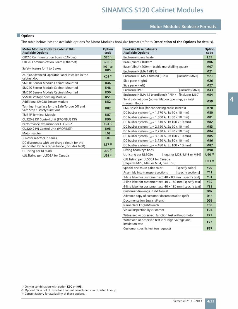
4
Siemens D21.7 – 2013 4/23
SINAMICS S120 Cabinet Modules
Line voltage 380 … 480 V 3 ph. ACDC bus voltage 510 … 720 V DC
Single Motor Module Booksize Cabinet Kit 6SL3720- 1TE24-5AU3
6SL3720-1TE26-0AU3
6SL3720-1TE28-5AU3
6SL3720-1TE31-3AU3
Rated power
• For IL (60 Hz, 460 V) 1) 2) kW [HP] 28 [30] 37 [40] 53 [60] 82 [100]• For IL (50 Hz, 400 V) 1) kW 24 32 46 71• For IH (60 Hz, 460 V) 1) 2) kW [HP] 24 [25] 32 [40] 42 [50] 65 [75]• For IH (50 Hz, 400 V) 1) kW 21 28 37 57Output current• Rated current IN A A 45 60 85 132
• Base load current IH 3) A 38 52 68 105
• Maximum current Imax A A 85 113 141 210
DC bus current Id 4) A 54 72 102 158 Current demand
• 24V DC A 1.2 1.2 1.5 1.5
DC bus capacitance F 1,175 1,410 1,880 2,820
Pulse frequency 5)
• Rated kHz 4 4 4 4
• Maximum (with derating) kHz 16 16 16 16
Power loss, max. 6)
• At 60 Hz 475V [50 Hz 400V] kW 0.43 [0.43] 0.59 [0.59] 0.75 [0.75] 1.25 [1.25]
Cooling air requirement cfm [m3/s] 65.7 [0.031] 65.7 [0.031] 93.2 [0.044] 305 [0.144]
Sound pressure level LpA (1m) dB(A) < 65 < 65 < 60 < 73
at 60 [50] Hz
Motor connection U2, V2, W2 Terminal Terminal Terminal Terminal
• Conductor size, max. #6 AWG #6 AWG 2/0 2/0
Output cable length, max. 7)
• Shielded ft [m] 328 [100] 328 [100] 328 [100] 328 [100]
• Unshielded ft [m] 492 [150] 492 [150] 492 [150] 492 [150]
Weight, approx. lb [kg] 60 [27] 60 [27] 73 [33] 90 [41]
Installation width mm 200 200 200 300
Short Circuit Current Rating(SCCR) per UL508A kA 65 65 65 65
Options
Motor Modules Booksize Formats
1) Only in combination with option K90 or K95.2) Option L37 is not UL listed and cannot be included in a UL listed line-up.3) Consult factory for availability of these options.
The table below lists the available options for Motor Modules booksize format (refer to Description of the Options for details).
Motor Module Booksize Cabinet KitsAvailable Options
Optioncode
CBC10 Communication Board (CANbus) G20 1)
CBE20 Communication Board (Ethernet) G33 1)
Safety license for 1 to 5 axes K01 to K05
AOP30 Advanced Operator Panel installed in the cabinet door K08 1)
SMC10 Sensor Module Cabinet-Mounted K46
SMC20 Sensor Module Cabinet-Mounted K48
SMC30 Sensor Module Cabinet-Mounted K50
VSM10 Voltage Sensing Module K51
Additional SMC30 Sensor Module K52
Terminal interface for the Safe Torque Off and Safe Stop 1 safety functions K82
TM54F Terminal Module K87
CU320-2 DP Control Unit (PROFIBUS DP) K90
Performance expansion for CU320-2 K94 1)
CU320-2 PN Control Unit (PROFINET) K95
Motor reactor L08
2 motor reactors in series L09
DC disconnect with pre-charge circuit for the associated DC bus capacitance (includes M60) L37 2)
UL listing per UL508A U90 3)
cUL listing per UL508A for Canada U91 3)
Booksize Base CabinetsAvailable Options
Optioncode
Enclosure space heater L55
Base (plinth) 100mm M06
Base (plinth) 200mm (cable marshalling space) M07
Enclosure NEMA 1 (IP21) M21
Enclosure NEMA 1 filtered (IP23) [includes M60] M23
Side panel (right) M26
Side panel (left) M27
Enclosure IP43 [includes M60] M43
Enclosure NEMA 12 (ventilated) (IP54) [includes M60] M54
Solid cabinet door (no ventilation openings, air inlet through floor)
M59
EMC shield bus (for connecting cable screens) M70
DC busbar system (Id = 1,170 A, 1x 60 x 10 mm) M80
DC busbar system (Id = 1,500 A, 1x 80 x 10 mm) M81
DC busbar system (Id = 1,840 A, 1x 100 x 10 mm) M82
DC busbar system (Id = 2,150 A, 2x 60 x 10 mm) M83
DC busbar system (Id = 2,730 A, 2x 80 x 10 mm) M84
DC busbar system (Id = 3,320 A, 2x 100 x 10 mm) M85
DC busbar system (Id = 3,720 A, 3x 80 x 10 mm) M86
DC busbar system (Id = 4,480 A, 3x 100 x 10 mm) M87
Lifting beam/eye bolts M90
UL listing per UL508A [requires M23, M43 or M54] U90 3)
cUL listing per UL508A for Canada [requires M23, M43 or M54, plus T58]
U91 3)
Special enclosure paint color [specify color] Y09
Assembly into transport sections [specify sections] Y11
1-line label for customer text, 40 x 80 mm [specify text] Y31
2-line label for customer text, 40 x 180 mm [specify text] Y32
4-line label for customer text, 40 x 180 mm [specify text] Y33
Customer drawings in dxf format D02
Advance copy of customer documentation (pdf) D14
Documentation English/French D58
Nameplate English/French T58
Visual Inspection by customer F03
Witnessed or observed function test without motor F71
Witnessed or observed test incl. high-voltage and insulation test
F77
Customer specific test (on request) F97
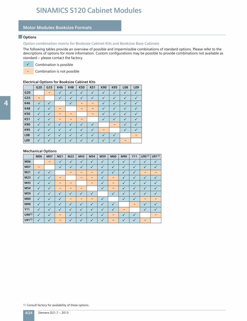
4
4/24 Siemens D21.7 – 2013
SINAMICS S120 Cabinet Modules
Motor Modules Booksize Formats
Options
Option combination matrix for Booksize Cabinet Kits and Booksize Base Cabinets
Thefollowingtablesprovideanoverviewofpossibleandimpermissiblecombinationsofstandardoptions.Pleaserefertothedescriptionsofoptionsformoreinformation.Customconfigurationsmaybepossibletoprovidecombinationsnotavailableasstandard–pleasecontactthefactory.
Combinationispossible
–Combinationisnotpossible
Electrical Options for Booksize Cabinet Kits
G20 G33 K46 K48 K50 K51 K90 K95 L08 L09
G20 –
G33 –
K46 – –
K48 – – –
K50 – – –
K51 – – –
K90 –
K95 –
L08 –
L09 –
Mechanical OptionsM06 M07 M21 M23 M43 M54 M59 M60 M90 Y11 U90 1) U911)
M06 –
M07 –
M21 – – – – –
M23 – – – –
M43 – – – –
M54 – – – –
M59
M60 – – – – –
M90 –
Y11 –
U901) – – –
U911) – – –
1)Consultfactoryforavailabilityoftheseoptions.
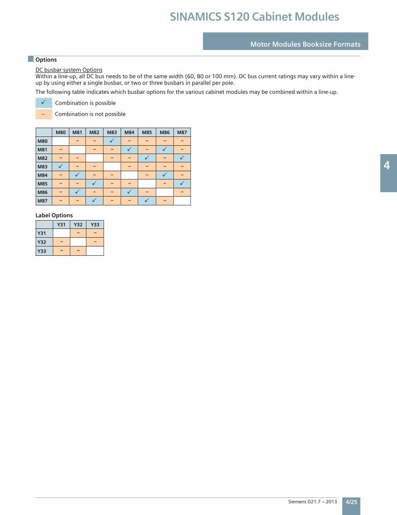
4
Siemens D21.7 – 2013 4/25
SINAMICS S120 Cabinet Modules
Options
Motor Modules Booksize Formats
DCbusbarsystemOptionsWithinaline-up,allDCbusneedstobeofthesamewidth(60,80or100mm).DCbuscurrentratingsmayvarywithinaline-upbyusingeitherasinglebusbar,ortwoorthreebusbarsinparallelperpole.
Thefollowingtableindicateswhichbusbaroptionsforthevariouscabinetmodulesmaybecombinedwithinaline-up.
Combinationispossible
–Combinationisnotpossible
M80 M81 M82 M83 M84 M85 M86 M87
M80 – – – – – –
M81 – – – – –
M82 – – – – –
M83 – – – – – –
M84 – – – – –
M85 – – – – –
M86 – – – – –
M87 – – – – –
Y31 Y32 Y33
Y31 – –
Y32 – –
Y33 – –
Label Options
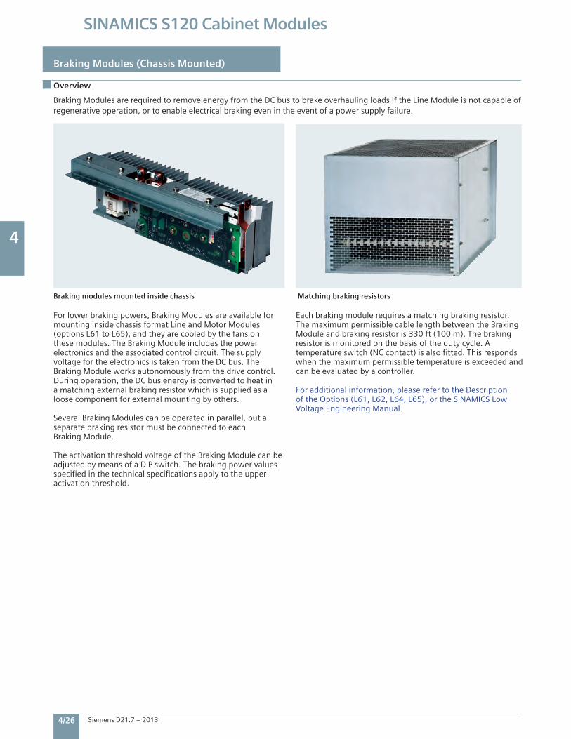
4
4/26 Siemens D21.7 – 2013
SINAMICS S120 Cabinet Modules
Braking Modules (Chassis Mounted)
Overview
For lower braking powers, Braking Modules are available for mounting inside chassis format Line and Motor Modules (options L61 to L65), and they are cooled by the fans on these modules. The Braking Module includes the power electronics and the associated control circuit. The supply voltage for the electronics is taken from the DC bus. The Braking Module works autonomously from the drive control. During operation, the DC bus energy is converted to heat in a matching external braking resistor which is supplied as a loose component for external mounting by others.
Several Braking Modules can be operated in parallel, but a separate braking resistor must be connected to each Braking Module.
The activation threshold voltage of the Braking Module can be adjusted by means of a DIP switch. The braking power values specified in the technical specifications apply to the upper activation threshold.
Each braking module requires a matching braking resistor.The maximum permissible cable length between the Braking Module and braking resistor is 330 ft (100 m). The braking resistor is monitored on the basis of the duty cycle. A temperature switch (NC contact) is also fitted. This responds when the maximum permissible temperature is exceeded and can be evaluated by a controller.
For additional information, please refer to the Description of the Options (L61, L62, L64, L65), or the SINAMICS Low Voltage Engineering Manual.
Braking Modules are required to remove energy from the DC bus to brake overhauling loads if the Line Module is not capable of regenerative operation, or to enable electrical braking even in the event of a power supply failure.
Braking modules mounted inside chassis Matching braking resistors
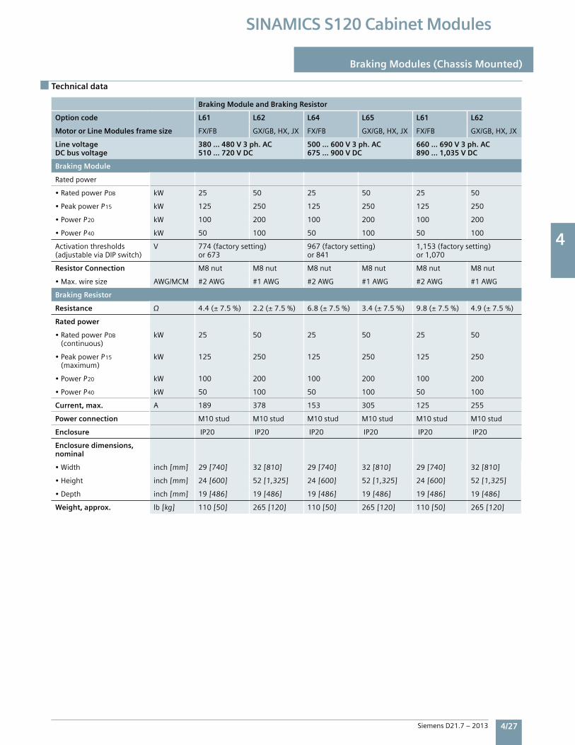
4
Siemens D21.7 – 2013 4/27
SINAMICS S120 Cabinet Modules
Technical data
Braking Modules (Chassis Mounted)
Braking Module and Braking Resistor
Option code L61 L62 L64 L65 L61 L62
Motor or Line Modules frame size FX/FB GX/GB,HX,JX FX/FB GX/GB,HX,JX FX/FB GX/GB,HX,JX
Line voltage DC bus voltage
380 … 480 V 3 ph. AC510 … 720 V DC
500 … 600 V 3 ph. AC675 … 900 V DC
660 … 690 V 3 ph. AC890 … 1,035 V DC
Braking Module
Ratedpower
•RatedpowerPDB kW 25 50 25 50 25 50
•PeakpowerP15 kW 125 250 125 250 125 250
•PowerP20 kW 100 200 100 200 100 200
•PowerP40 kW 50 100 50 100 50 100
Activationthresholds(adjustableviaDIPswitch)
V 774(factorysetting)or673
967(factorysetting)or841
1,153(factorysetting)or1,070
Resistor Connection M8nut M8nut M8nut M8nut M8nut M8nut
•Max.wiresize AWG/MCM #2AWG #1AWG #2AWG #1AWG #2AWG #1AWG
Braking Resistor
Resistance 4.4(±7.5%) 2.2(±7.5%) 6.8(±7.5%) 3.4(±7.5%) 9.8(±7.5%) 4.9(±7.5%)
Rated power
•RatedpowerPDB
(continuous)kW 25 50 25 50 25 50
•PeakpowerP15
(maximum)kW 125 250 125 250 125 250
•PowerP20 kW 100 200 100 200 100 200
•PowerP40 kW 50 100 50 100 50 100
Current, max. A 189 378 153 305 125 255
Power connection M10stud M10stud M10stud M10stud M10stud M10stud
Enclosure IP20 IP20 IP20 IP20 IP20 IP20
Enclosure dimensions, nominal
•Width inch[mm] 29[740] 32[810] 29[740] 32[810] 29[740] 32[810]
•Height inch[mm] 24[600] 52[1,325] 24[600] 52[1,325] 24[600] 52[1,325]
•Depth inch[mm] 19[486] 19[486] 19[486] 19[486] 19[486] 19[486]
Weight, approx. lb[kg] 110[50] 265[120] 110[50] 265[120] 110[50] 265[120]
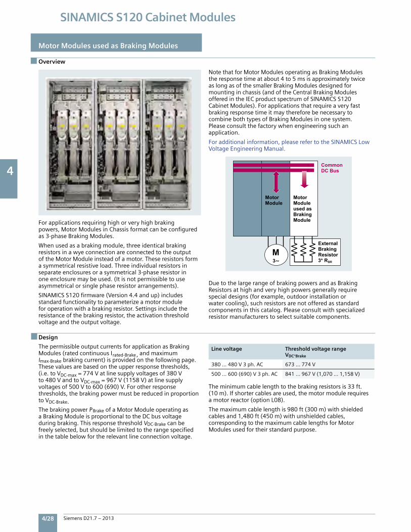
4
4/28 Siemens D21.7 – 2013
SINAMICS S120 Cabinet Modules
Motor Modules used as Braking Modules
Braking Modules (Chassis Mounted)
Overview
Forapplicationsrequiringhighorveryhighbrakingpowers,MotorModulesinChassisformatcanbeconfiguredas3-phaseBrakingModules.
Whenusedasabrakingmodule,threeidenticalbrakingresistorsinawyeconnectionareconnectedtotheoutputoftheMotorModuleinsteadofamotor.Theseresistorsformasymmetricalresistiveload.Threeindividualresistorsinseparateenclosuresorasymmetrical3-phaseresistorinoneenclosuremaybeused.(Itisnotpermissibletouseasymmetricalorsinglephaseresistorarrangements).
SINAMICSS120firmware(Version4.4andup)includesstandardfunctionalitytoparameterizeamotormoduleforoperationwithabrakingresistor.Settingsincludetheresistanceofthebrakingresistor,theactivationthresholdvoltageandtheoutputvoltage.
NotethatforMotorModulesoperatingasBrakingModulestheresponsetimeatabout4to5msisapproximatelytwiceaslongasofthesmallerBrakingModulesdesignedformountinginchassis(andoftheCentralBrakingModulesofferedintheIECproductspectrumofSINAMICSS120CabinetModules).ForapplicationsthatrequireaveryfastbrakingresponsetimeitmaythereforebenecessarytocombinebothtypesofBrakingModulesinonesystem.Pleaseconsultthefactorywhenengineeringsuchanapplication.
Foradditionalinformation,pleaserefertotheSINAMICSLowVoltageEngineeringManual.
DuetothelargerangeofbrakingpowersandasBrakingResistorsathighandveryhighpowersgenerallyrequirespecialdesigns(forexample,outdoorinstallationorwatercooling),suchresistorsarenotofferedasstandardcomponentsinthiscatalog.Pleaseconsultwithspecializedresistormanufacturerstoselectsuitablecomponents.
Design
ThepermissibleoutputcurrentsforapplicationasBrakingModules(ratedcontinuousIrated-Brake,andmaximumImax-Brakebrakingcurrent)isprovidedonthefollowingpage.Thesevaluesarebasedontheupperresponsethresholds,(i.e.toVDC-max=774Vatlinesupplyvoltagesof380Vto480VandtoVDC-max=967V(1158V)atlinesupplyvoltagesof500Vto600(690)V.Forotherresponsethresholds,thebrakingpowermustbereducedinproportiontoVDC-Brake.ThebrakingpowerPBrakeofaMotorModuleoperatingasaBrakingModuleisproportionaltotheDCbusvoltageduringbraking.ThisresponsethresholdVDC-Brakecanbefreelyselected,butshouldbelimitedtotherangespecifiedinthetablebelowfortherelevantlineconnectionvoltage.
Line voltage Threshold voltage rangeVDC-Brake
380…480V3ph.AC 673…774V
500…600(690)V3ph.AC 841…967V(1,070…1,158V)
Theminimumcablelengthtothebrakingresistorsis33ft.(10m).Ifshortercablesareused,themotormodulerequiresamotorreactor(optionL08).
Themaximumcablelengthis980ft(300m)withshieldedcablesand1,480ft(450m)withunshieldedcables,correspondingtothemaximumcablelengthsforMotorModulesusedfortheirstandardpurpose.
Motor Module
Motor Moduleused asBraking Module
Common DC Bus
ExternalBraking Resistor3* RBR
M
3
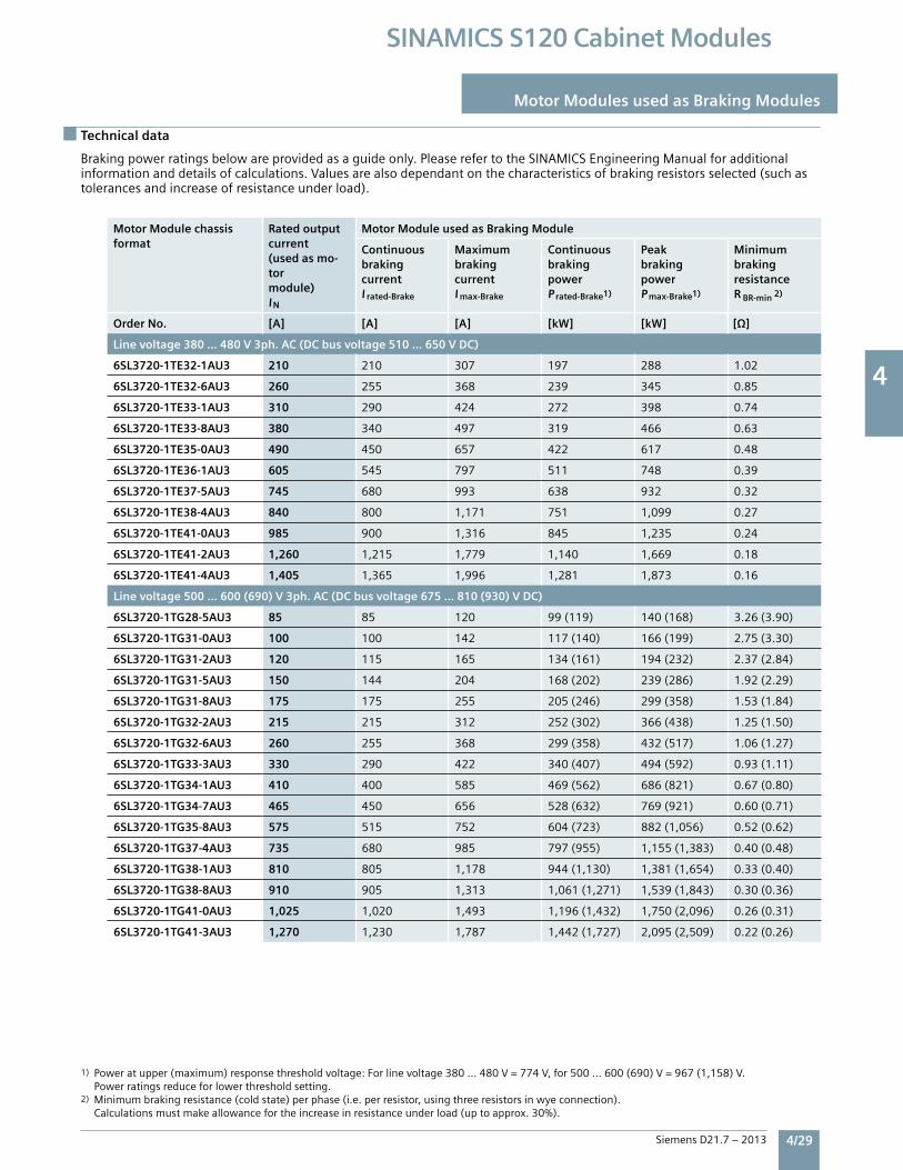
4
Siemens D21.7 – 2013 4/29
SINAMICS S120 Cabinet Modules
Technical data
Motor Modules used as Braking Modules
Brakingpowerratingsbelowareprovidedasaguideonly.PleaserefertotheSINAMICSEngineeringManualforadditionalinformationanddetailsofcalculations.Valuesarealsodependantonthecharacteristicsofbrakingresistorsselected(suchastolerancesandincreaseofresistanceunderload).
1) Poweratupper(maximum)responsethresholdvoltage:Forlinevoltage380…480V=774V,for500…600(690)V=967(1,158)V. Powerratingsreduceforlowerthresholdsetting.2) Minimumbrakingresistance(coldstate)perphase(i.e.perresistor,usingthreeresistorsinwyeconnection). Calculationsmustmakeallowancefortheincreaseinresistanceunderload(uptoapprox.30%).
Motor Module chassis format
Rated output current (used as mo-tor module) IN
Motor Module used as Braking Module
Continuous braking currentI rated-Brake
MaximumbrakingcurrentI max-Brake
ContinuousbrakingpowerP rated-Brake1)
PeakbrakingpowerP max-Brake1)
MinimumbrakingresistanceR BR-min 2)
Order No. [A] [A] [A] [kW] [kW]
Line voltage 380 … 480 V 3ph. AC (DC bus voltage 510 … 650 V DC)
6SL3720-1TE32-1AU3 210 210 307 197 288 1.02
6SL3720-1TE32-6AU3 260 255 368 239 345 0.85
6SL3720-1TE33-1AU3 310 290 424 272 398 0.74
6SL3720-1TE33-8AU3 380 340 497 319 466 0.63
6SL3720-1TE35-0AU3 490 450 657 422 617 0.48
6SL3720-1TE36-1AU3 605 545 797 511 748 0.39
6SL3720-1TE37-5AU3 745 680 993 638 932 0.32
6SL3720-1TE38-4AU3 840 800 1,171 751 1,099 0.27
6SL3720-1TE41-0AU3 985 900 1,316 845 1,235 0.24
6SL3720-1TE41-2AU3 1,260 1,215 1,779 1,140 1,669 0.18
6SL3720-1TE41-4AU3 1,405 1,365 1,996 1,281 1,873 0.16
Line voltage 500 … 600 (690) V 3ph. AC (DC bus voltage 675 … 810 (930) V DC)
6SL3720-1TG28-5AU3 85 85 120 99(119) 140(168) 3.26(3.90)
6SL3720-1TG31-0AU3 100 100 142 117(140) 166(199) 2.75(3.30)
6SL3720-1TG31-2AU3 120 115 165 134(161) 194(232) 2.37(2.84)
6SL3720-1TG31-5AU3 150 144 204 168(202) 239(286) 1.92(2.29)
6SL3720-1TG31-8AU3 175 175 255 205(246) 299(358) 1.53(1.84)
6SL3720-1TG32-2AU3 215 215 312 252(302) 366(438) 1.25(1.50)
6SL3720-1TG32-6AU3 260 255 368 299(358) 432(517) 1.06(1.27)
6SL3720-1TG33-3AU3 330 290 422 340(407) 494(592) 0.93(1.11)
6SL3720-1TG34-1AU3 410 400 585 469(562) 686(821) 0.67(0.80)
6SL3720-1TG34-7AU3 465 450 656 528(632) 769(921) 0.60(0.71)
6SL3720-1TG35-8AU3 575 515 752 604(723) 882(1,056) 0.52(0.62)
6SL3720-1TG37-4AU3 735 680 985 797(955) 1,155(1,383) 0.40(0.48)
6SL3720-1TG38-1AU3 810 805 1,178 944(1,130) 1,381(1,654) 0.33(0.40)
6SL3720-1TG38-8AU3 910 905 1,313 1,061(1,271) 1,539(1,843) 0.30(0.36)
6SL3720-1TG41-0AU3 1,025 1,020 1,493 1,196(1,432) 1,750(2,096) 0.26(0.31)
6SL3720-1TG41-3AU3 1,270 1,230 1,787 1,442(1,727) 2,095(2,509) 0.22(0.26)
4
4/30 Siemens D21.7 – 2013
SINAMICS S120 Cabinet Modules
Notes
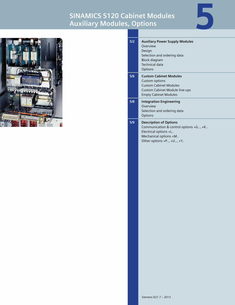
5
SINAMICS S120 Cabinet ModulesAuxiliary Modules, Options
5/2 Auxiliary Power Supply Modules Overview Design Selectionandorderingdata Blockdiagram Technicaldata Options
5/6 Custom Cabinet Modules Customoptions CustomCabinetModules CustomCabinetModuleline-ups EmptyCabinetModules
5/8 Integration Engineering Overview Selectionandorderingdata Options
5/9 Description of Options Communication&controloptions+G..,+K.. Electricaloptions+L.. Mechanicaloptions+M.. Otheroptions+P..,+U..,+Y..
5
SiemensD21.7–2013
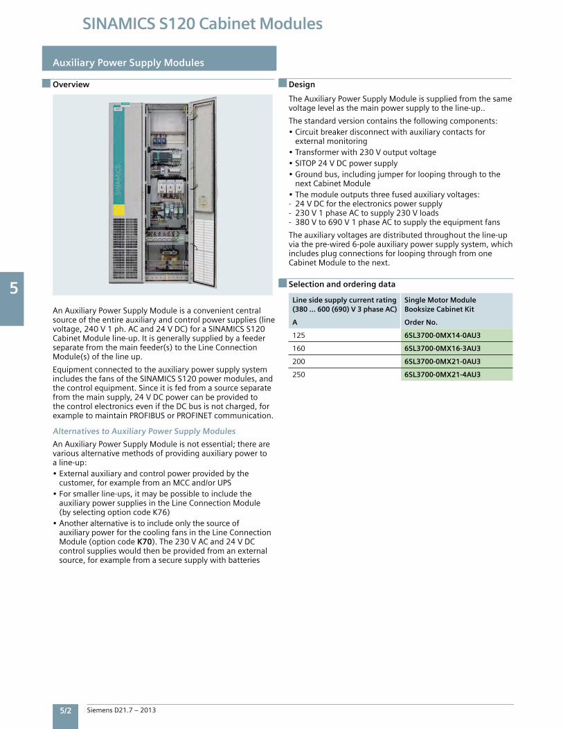
5
5/2 Siemens D21.7 – 2013
SINAMICS S120 Cabinet Modules
Overview Overview
Auxiliary Power Supply Modules
AnAuxiliaryPowerSupplyModuleisaconvenientcentralsourceoftheentireauxiliaryandcontrolpowersupplies(linevoltage,240V1ph.ACand24VDC)foraSINAMICSS120CabinetModuleline-up.Itisgenerallysuppliedbyafeederseparatefromthemainfeeder(s)totheLineConnectionModule(s)ofthelineup.
EquipmentconnectedtotheauxiliarypowersupplysystemincludesthefansoftheSINAMICSS120powermodules,andthecontrolequipment.Sinceitisfedfromasourceseparatefromthemainsupply,24VDCpowercanbeprovidedtothecontrolelectronicseveniftheDCbusisnotcharged,forexampletomaintainPROFIBUSorPROFINETcommunication.
Alternatives to Auxiliary Power Supply Modules
AnAuxiliaryPowerSupplyModuleisnotessential;therearevariousalternativemethodsofprovidingauxiliarypowertoaline-up:•Externalauxiliaryandcontrolpowerprovidedbythe customer,forexamplefromanMCCand/orUPS•Forsmallerline-ups,itmaybepossibletoincludethe auxiliarypowersuppliesintheLineConnectionModule (byselectingoptioncodeK76)•Anotheralternativeistoincludeonlythesourceof auxiliarypowerforthecoolingfansintheLineConnection Module(optioncodeK70).The230VACand24VDC controlsupplieswouldthenbeprovidedfromanexternal source,forexamplefromasecuresupplywithbatteries
TheAuxiliaryPowerSupplyModuleissuppliedfromthesamevoltagelevelasthemainpowersupplytotheline-up..
Thestandardversioncontainsthefollowingcomponents:•Circuitbreakerdisconnectwithauxiliarycontactsfor externalmonitoring•Transformerwith230Voutputvoltage•SITOP24VDCpowersupply•Groundbus,includingjumperforloopingthroughtothe nextCabinetModule•Themoduleoutputsthreefusedauxiliaryvoltages:- 24VDCfortheelectronicspowersupply- 230V1phaseACtosupply230Vloads- 380Vto690V1phaseACtosupplytheequipmentfans
Theauxiliaryvoltagesaredistributedthroughouttheline-upviathepre-wired6-poleauxiliarypowersupplysystem,whichincludesplugconnectionsforloopingthroughfromoneCabinetModuletothenext.
Line side supply current rating (380 … 600 (690) V 3 phase AC)
Single Motor ModuleBooksize Cabinet Kit
A Order No.
125 6SL3700-0MX14-0AU3
160 6SL3700-0MX16-3AU3
200 6SL3700-0MX21-0AU3
250 6SL3700-0MX21-4AU3
Design
Selection and ordering data
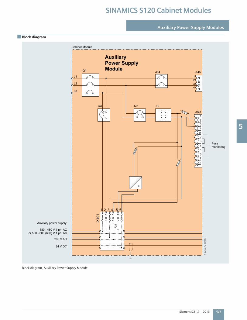
5
Siemens D21.7 – 2013 5/3
SINAMICS S120 Cabinet Modules
Block diagram
Auxiliary Power Supply Modules
Blockdiagram,AuxiliaryPowerSupplyModule
1 2 3 4 5 6
Fusemonitoring
24 V DC
230 V AC
380 - 480 V 1 ph. ACor 500 - 600 (690) V 1 ph. AC
Auxiliary power supply:
G_D
213_
EN
_000
67b
Auxiliary Power SupplyModule
Cabinet Module
18
14 1516 17
4 11 12 13
1 2 3
-Q4
-T2
~
=
-Q2-Q3
L3
L2
L1
-Q1
4321
-X47
-X45
-X10
1
-F24
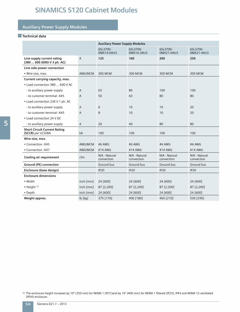
5
5/4 Siemens D21.7 – 2013
SINAMICS S120 Cabinet Modules
Technical data
Auxiliary Power Supply Modules
1) Theenclosureheightincreasesby10”(250mm)forNEMA1(IP21)andby16”(400mm)forNEMA1filtered(IP23),IP43andNEMA12ventilated (IP54)enclosure.
Auxiliary Power Supply Modules
6SL3700-0MX14-0AU3
6SL3700-0MX16-3AU3
6SL3700-0MX21-0AU3
6SL3700-0MX21-4AU3
Line supply current rating (380 … 600 (690) V 3 ph. AC)
A 125 160 200 250
Line side power connection
•Wiresize,max. AWG/MCM 300MCM 300MCM 300MCM 300MCM
Current carrying capacity, max.
•Loadconnection380...690VAC
-toauxiliarypowersupply A 63 80 100 100
-tocustomerterminal-X45 A 50 63 80 80
•Loadconnection230V1ph.AC
-toauxiliarypowersupply A 6 10 10 20
-tocustomerterminal-X45 A 8 10 10 20
•Loadconnection24VDC
-toauxiliarypowersupply A 20 40 80 80
Short Circuit Current Rating(SCCR) perUL508A kA 100 100 100 100
Wire size, max.
•Connection-X45 AWG/MCM #6AWG #6AWG #6AWG #6AWG
•Connection-X47 AWG/MCM #14AWG #14AWG #14AWG #14AWG
Cooling air requirement cfm N/A-Naturalconvection
N/A-Naturalconvection
N/A-Naturalconvection
N/A-Naturalconvection
Ground (PE) connection Groundbus Groundbus Groundbus Groundbus
Enclosure (base design) IP20 IP20 IP20 IP20
Enclosure dimensions
•Width inch[mm] 24[600] 24[600] 24[600] 24[600]
•Height1) inch[mm] 87[2,200] 87[2,200] 87[2,200] 87[2,200]
•Depth inch[mm] 24[600] 24[600] 24[600] 24[600]
Weight approx. lb[kg] 375[170] 400[180] 465[210] 530[240]
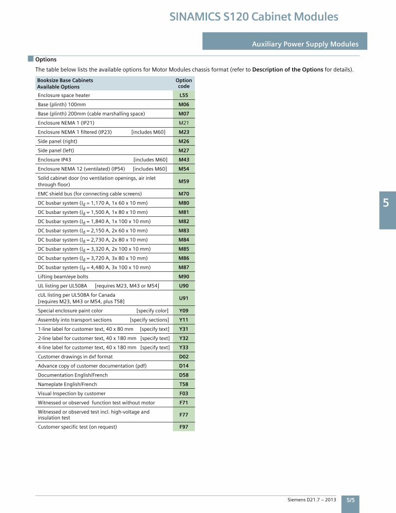
5
Siemens D21.7 – 2013 5/5
SINAMICS S120 Cabinet Modules
Options
Auxiliary Power Supply Modules
Auxiliary Power Supply Modules
6SL3700-0MX14-0AU3
6SL3700-0MX16-3AU3
6SL3700-0MX21-0AU3
6SL3700-0MX21-4AU3
Line supply current rating (380 … 600 (690) V 3 ph. AC)
A 125 160 200 250
Line side power connection
•Wiresize,max. AWG/MCM 300MCM 300MCM 300MCM 300MCM
Current carrying capacity, max.
•Loadconnection380...690VAC
-toauxiliarypowersupply A 63 80 100 100
-tocustomerterminal-X45 A 50 63 80 80
•Loadconnection230V1ph.AC
-toauxiliarypowersupply A 6 10 10 20
-tocustomerterminal-X45 A 8 10 10 20
•Loadconnection24VDC
-toauxiliarypowersupply A 20 40 80 80
Short Circuit Current Rating(SCCR) perUL508A kA 100 100 100 100
Wire size, max.
•Connection-X45 AWG/MCM #6AWG #6AWG #6AWG #6AWG
•Connection-X47 AWG/MCM #14AWG #14AWG #14AWG #14AWG
Cooling air requirement cfm N/A-Naturalconvection
N/A-Naturalconvection
N/A-Naturalconvection
N/A-Naturalconvection
Ground (PE) connection Groundbus Groundbus Groundbus Groundbus
Enclosure (base design) IP20 IP20 IP20 IP20
Enclosure dimensions
•Width inch[mm] 24[600] 24[600] 24[600] 24[600]
•Height1) inch[mm] 87[2,200] 87[2,200] 87[2,200] 87[2,200]
•Depth inch[mm] 24[600] 24[600] 24[600] 24[600]
Weight approx. lb[kg] 375[170] 400[180] 465[210] 530[240]
ThetablebelowliststheavailableoptionsforMotorModuleschassisformat(refertoDescription of the Optionsfordetails).
Booksize Base Cabinets Available Options
Optioncode
Enclosurespaceheater L55
Base(plinth)100mm M06
Base(plinth)200mm(cablemarshallingspace) M07
EnclosureNEMA1(IP21) M21
EnclosureNEMA1filtered(IP23)[includesM60] M23
Sidepanel(right) M26
Sidepanel(left) M27
EnclosureIP43[includesM60] M43
EnclosureNEMA12(ventilated)(IP54)[includesM60] M54
Solidcabinetdoor(noventilationopenings,airinletthroughfloor)
M59
EMCshieldbus(forconnectingcablescreens) M70
DCbusbarsystem(Id=1,170A,1x60x10mm) M80
DCbusbarsystem(Id=1,500A,1x80x10mm) M81
DCbusbarsystem(Id=1,840A,1x100x10mm) M82
DCbusbarsystem(Id=2,150A,2x60x10mm) M83
DCbusbarsystem(Id=2,730A,2x80x10mm) M84
DCbusbarsystem(Id=3,320A,2x100x10mm) M85
DCbusbarsystem(Id=3,720A,3x80x10mm) M86
DCbusbarsystem(Id=4,480A,3x100x10mm) M87
Liftingbeam/eyebolts M90
ULlistingperUL508A[requiresM23,M43orM54] U90
cULlistingperUL508AforCanada[requiresM23,M43orM54,plusT58]
U91
Specialenclosurepaintcolor[specifycolor] Y09
Assemblyintotransportsections[specifysections] Y11
1-linelabelforcustomertext,40x80mm[specifytext] Y31
2-linelabelforcustomertext,40x180mm[specifytext] Y32
4-linelabelforcustomertext,40x180mm[specifytext] Y33
Customerdrawingsindxfformat D02
Advancecopyofcustomerdocumentation(pdf) D14
DocumentationEnglish/French D58
NameplateEnglish/French T58
VisualInspectionbycustomer F03
Witnessedorobservedfunctiontestwithoutmotor F71
Witnessedorobservedtestincl.high-voltageandinsulationtest F77
Customerspecifictest(onrequest) F97

5
5/6 Siemens D21.7 – 2013
SINAMICS S120 Cabinet Modules
Auxiliary Power Supply Modules
Options
Option combination matrix for Auxiliary Power Supply Modules
Thefollowingtablesprovideanoverviewofpossibleandimpermissiblecombinationsofstandardoptions.Pleaserefertothedescriptionsofoptionsformoreinformation.Customconfigurationsmaybepossibletoprovidecombinationsnotavailableasstandard–pleasecontactthefactory.
Combinationispossible
–Combinationisnotpossible
DCbusbarsystemOptionsWithinaline-up,allDCbusneedstobeofthesamewidth(60,80or100mm).DCbuscurrentratingsmayvarywithinaline-upbyusingeitherasinglebusbar,ortwoorthreebusbarsinparallelperpole.
Thefollowingtableindicateswhichbusbaroptionsforthevariouscabinetmodulesmaybecombinedwithinaline-up.
M80 M81 M82 M83 M84 M85 M86 M87
M80 – – – – – –
M81 – – – – –
M82 – – – – –
M83 – – – – – –
M84 – – – – –
M85 – – – – –
M86 – – – – –
M87 – – – – –
Y31 Y32 Y33
Y31 – –
Y32 – –
Y33 – –
Label Options
Mechanical OptionsM06 M07 M21 M23 M43 M54 M59 M60 M90 Y11 U90 U91
M06 –
M07 –
M21 – – – – –
M23 – – – –
M43 – – – –
M54 – – – –
M59
M60 – – – – –
M90 –
Y11 –
U90 – – –
U91 – – –
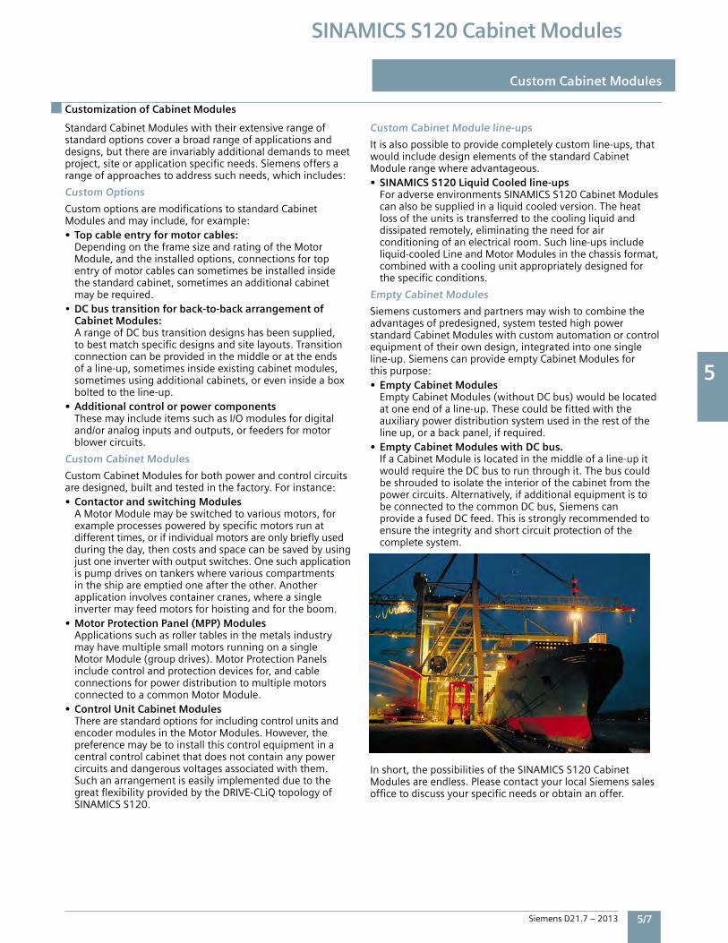
5
Siemens D21.7 – 2013 5/7
SINAMICS S120 Cabinet Modules
Customization of Cabinet Modules
Custom Cabinet Modules
StandardCabinetModuleswiththeirextensiverangeofstandardoptionscoverabroadrangeofapplicationsanddesigns,butthereareinvariablyadditionaldemandstomeetproject,siteorapplicationspecificneeds.Siemensoffersarangeofapproachestoaddresssuchneeds,whichincludes:
Custom Options
CustomoptionsaremodificationstostandardCabinetModulesandmayinclude,forexample:• Top cable entry for motor cables: DependingontheframesizeandratingoftheMotor Module,andtheinstalledoptions,connectionsfortop entryofmotorcablescansometimesbeinstalledinside thestandardcabinet,sometimesanadditionalcabinet mayberequired.• DC bus transition for back-to-back arrangement of Cabinet Modules: ArangeofDCbustransitiondesignshasbeensupplied, tobestmatchspecificdesignsandsitelayouts.Transition connectioncanbeprovidedinthemiddleorattheends ofaline-up,sometimesinsideexistingcabinetmodules, sometimesusingadditionalcabinets,oreveninsideabox boltedtotheline-up.• Additional control or power components ThesemayincludeitemssuchasI/Omodulesfordigital and/oranaloginputsandoutputs,orfeedersformotor blowercircuits.
Custom Cabinet Modules
CustomCabinetModulesforbothpowerandcontrolcircuitsaredesigned,builtandtestedinthefactory.Forinstance:• Contactor and switching Modules AMotorModulemaybeswitchedtovariousmotors,for exampleprocessespoweredbyspecificmotorsrunat differenttimes,orifindividualmotorsareonlybrieflyused duringtheday,thencostsandspacecanbesavedbyusing justoneinverterwithoutputswitches.Onesuchapplication ispumpdrivesontankerswherevariouscompartments intheshipareemptiedoneaftertheother.Another applicationinvolvescontainercranes,whereasingle invertermayfeedmotorsforhoistingandfortheboom.• Motor Protection Panel (MPP) Modules Applicationssuchasrollertablesinthemetalsindustry mayhavemultiplesmallmotorsrunningonasingle MotorModule(groupdrives).MotorProtectionPanels includecontrolandprotectiondevicesfor,andcable connectionsforpowerdistributiontomultiplemotors connectedtoacommonMotorModule.• Control Unit Cabinet Modules Therearestandardoptionsforincludingcontrolunitsand encodermodulesintheMotorModules.However,the preferencemaybetoinstallthiscontrolequipmentina centralcontrolcabinetthatdoesnotcontainanypower circuitsanddangerousvoltagesassociatedwiththem. Suchanarrangementiseasilyimplementedduetothe greatflexibilityprovidedbytheDRIVE-CLiQtopologyof SINAMICSS120.
Custom Cabinet Module line-ups
Itisalsopossibletoprovidecompletelycustomline-ups,thatwouldincludedesignelementsofthestandardCabinetModulerangewhereadvantageous.• SINAMICS S120 Liquid Cooled line-ups ForadverseenvironmentsSINAMICSS120CabinetModules canalsobesuppliedinaliquidcooledversion.Theheat lossoftheunitsistransferredtothecoolingliquidand dissipatedremotely,eliminatingtheneedforair conditioningofanelectricalroom.Suchline-upsinclude liquid-cooledLineandMotorModulesinthechassisformat, combinedwithacoolingunitappropriatelydesignedfor thespecificconditions.
Empty Cabinet Modules
Siemenscustomersandpartnersmaywishtocombinetheadvantagesofpredesigned,systemtestedhighpowerstandardCabinetModuleswithcustomautomationorcontrolequipmentoftheirowndesign,integratedintoonesingleline-up.SiemenscanprovideemptyCabinetModulesforthispurpose:• Empty Cabinet Modules EmptyCabinetModules(withoutDCbus)wouldbelocated atoneendofaline-up.Thesecouldbefittedwiththe auxiliarypowerdistributionsystemusedintherestofthe lineup,orabackpanel,ifrequired.• Empty Cabinet Modules with DC bus. IfaCabinetModuleislocatedinthemiddleofaline-upit wouldrequiretheDCbustorunthroughit.Thebuscould beshroudedtoisolatetheinteriorofthecabinetfromthe powercircuits.Alternatively,ifadditionalequipmentisto beconnectedtothecommonDCbus,Siemenscan provideafusedDCfeed.Thisisstronglyrecommendedto ensuretheintegrityandshortcircuitprotectionofthe completesystem.
Inshort,thepossibilitiesoftheSINAMICSS120CabinetModulesareendless.PleasecontactyourlocalSiemenssalesofficetodiscussyourspecificneedsorobtainanoffer.
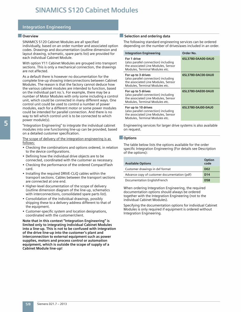
5
5/8 Siemens D21.7 – 2013
SINAMICS S120 Cabinet Modules
Integration Engineering
Overview
SINAMICSS120CabinetModulesareallspecifiedindividually,basedonanordernumberandassociatedoptioncodes.Drawingsanddocumentation(outlinedimensionandlayoutdrawing,schematic,sparepartslist)areprovidedforeachindividualCabinetModule.
WithoptionY11CabinetModulesaregroupedintotransportsections.Thisisonlyamechanicalconnection,thedrawingsarenotaffected.
Asadefaultthereishowevernodocumentationforthecompleteline-upshowinginterconnectionsbetweenCabinetModules.Thereasonisthatthefactorycannotdeducehowthevariouscabinetmodulesareintendedtofunction,basedontheindividualpartno.’s.Forexample,theremaybeanumberofMotorModuleswithonlysomeincludingacontrolunit,whichcouldbeconnectedinmanydifferentways.Onecontrolunitcouldbeusedtocontrolanumberofpowermodules,eachforadifferentmotororsomepowermodulescouldbeintendedforparallelconnection.Andthereisnowaytotellwhichcontrolunitistobeconnectedtowhichpowermodule(s).
“IntegrationEngineering”tointegratetheindividualcabinetmodulesintoonefunctioningline-upcanbeprovided,basedonadetailedcustomerspecification.
Thescopeofdeliveryoftheintegrationengineeringisasfollows:• Checkingthecombinationsandoptionsordered,inrelation tothedeviceconfigurations.• Defininghowtheindividualdriveobjectsaretobe connected,coordinatedwiththecustomerasnecessary.• CheckingtheperformanceoftheorderedCompactFlash card.• InstallingtherequiredDRIVE-CLiQcableswithinthe transportsections.Cablesbetweenthetransportsections areconnectedatoneend.• Higher-leveldocumentationofthescopeofdelivery (outlinedimensiondiagramoftheline-up,schematics withinterconnections,consolidatedsparepartslist).• Consolidationoftheindividualdrawings,possibly shippingthesetoadeliveryaddressdifferenttothatof theequipment.• Customer-specificsystemandlocationdesignations, coordinatedwiththecustomer/client.
Note that in this context “Integration Engineering” is limited only to integrating individual Cabinet Modules into a line-up. This is not to be confused with integration of the drive line-up into the customer’s plant and interconnection to external equipment such as power supplies, motors and process control or automation equipment, which is outside the scope of supply of a Cabinet Module line-up!
Thefollowingstandardengineeringservicescanbeordereddependingonthenumberofdrives/axesincludedinanorder.
Integration Engineering Order No.
For 1 drive(alsoparallelconnection)includingtheassociatedLineModules,SensorModules,TerminalModulesetc.
6SL3780-0AA00-0AU0
For up to 3 drives(alsoparallelconnection)includingtheassociatedLineModules,SensorModules,TerminalModulesetc.
6SL3780-0AC00-0AU0
For up to 5 drives (alsoparallelconnection)includingtheassociatedLineModules,SensorModules,TerminalModulesetc.
6SL3780-0AE00-0AU0
For up to 10 drives(alsoparallelconnection)includingtheassociatedLineModules,SensorModules,TerminalModulesetc.
6SL3780-0AJ00-0AU0
Engineeringservicesforlargerdrivesystemsisalsoavailableonrequest.
Options
ThetablebelowliststheoptionsavailablefortheorderspecificIntegrationEngineering(FordetailsseeDescriptionoftheoptions):
Available OptionsOption code
Customerdrawingsindxfformat D02
Advancecopyofcustomerdocumentation(pdf) D14
DocumentationEnglish/French D58
WhenorderingIntegrationEngineering,therequireddocumentationoptionsshouldalwaysbeorderedtogetherwiththeIntegrationEngineering(nottotheindividualCabinetModules).
SpecifyingthedocumentationoptionsforindividualCabinetModulesisonlyrequiredifequipmentisorderedwithoutIntegrationEngineering.
Selection and ordering data
5
Siemens D21.7 – 2013 5/9
SINAMICS S120 Cabinet Modules
Description of options
Description of Options
Standard documentation
• CustomerdrawingssuppliedwithSINAMICSS120Cabinet Modulesareprovidedforeachcabinetindividually(unless IntegrationEngineeringisorderedtoprovidesystem drawings)andarealwaysjobspecific(showingthe configurationactuallysupplied,optionsnotprovidedare notshown).• Allcustomerdocumentationisprovidedinelectronic formatonaCD,whichshipsinsidethedrive.Alldocuments areinpdfformat(AdobeAcrobat)andaresuppliedin EnglishwithacopyinSpanish(English/Spanisharethe defaultlanguagesforNEMAversionCabinetModuleswith ordernumberendingin“U3”.English/Frenchisalternatively availablebyspecifyingoptionD58).Inaddition,apaper copyoftheSafetyandTransportationGuidelinesandthe InstallationCheckListareincludedtoo.
D02 Customer drawings in dxf format
Schematics,outlinedimensionandlayoutdrawingswillbeprovidedinAutoCAD(dxf)ontheCD(orasspecifiedbyotheroptioncodes).
D14Advance copy of customer documentation (pdf)
Toreceiveacopyofcustomerdrawingsearlierthanwithdriveshipment,i.e.afterorderplacement(typicallywithin2weeks).IfoptioncodeD02isspecified,theadvancecopyofthedrawingswillbesuppliedindxfformattoo.
D58Documentation English/French
Twocopiesofthedocumentation(drawingsandmanuals)willbeprovidedontheCD(orasspecifiedbyotheroptioncodes),oneinEnglishandtheotherinFrench.
F03, F71, F75, F77, F97Witnessed (or observed) testing
Order code Description
F03 Visualinspectionbycustomer
Thescopeoftheinspectioncomprises:•Checkingtheenclosuretype•Checkingtheequipment(components)•Checkingtheequipmentidentifiers•Checkingtheclearanceandcreepagedistances•Checkingthewires•Checkingthecustomerdocumentation•Submittingtheacceptancereport•Thechecksarecarriedoutwiththedrivedeenergized
F71 Witnessedfunctiontestofdrivewithoutmotor
Thescopeofthewitnessedtestcomprises:•VisualinspectionasperoptionF03•Checkofpowersupply•Checkofprotectiveandmonitoringdevices(simulation)•Checkoffans•Prechargingtest•Functionaltestwithoutconnectedmotor•Submittingtheacceptancereport
Afterthevisualinspectionwiththedriveswitchedoff,thedriveisconnectedtoratedvoltage.Nocurrentflowsatthedriveoutput.
F77 Witnessedtestincl.high-voltageandinsulationtest
Thescopeoftheacceptancecomprises:•High-voltagetest•Measurementofinsulationresistance
F97 Witnessedcustomerspecificdriveacceptanceinspections/tests(onrequest)
IfadditionalwitnessedtestingisdesiredoverandaboveoptionsF03orF71,pleaseprovideaspecification/testplanforthefactorytosubmitaquotation.
5
5/10 Siemens D21.7 – 2013
SINAMICS S120 Cabinet Modules
Description of Options
Description of options
G20CBC10 Communication Board CANopen
TheCBC10communicationboardisusedtointerfacetheCU320-2ControlUnitofaSINAMICSS120CabinetModuletotheCAN(ControllerAreaNetwork)protocol.Theboard’sdriversoftwarefulfillsthestandardsofthefollowingCANopenspecificationoftheCiAorganization(CANinAutomation):• CommunicationprofilesinaccordancewithDS301• DriveprofileinaccordancewithDSP402(inthiscaseProfile VelocityMode)• EDS(ElectronicDataSheet)inaccordancewithDSP306• OperatingstatussignalinginaccordancewithDSP305
TheCBC10CommunicationBoardplugsintotheoptionslotontheCU320-2ControlUnit.TheCANinterfaceontheCBC10has2SUB-Dconnectionsforinputandoutput.
TheCBC10CommunicationBoardcanonlybeorderedinconjunctionwithaCU320-2ControlUnit(optionK90orK95).NotetheCU320-2hasonlyoneoptionsslotforonecommunicationsorI/Omodule.
G33CBE20 Communication Board Ethernet
TheCBE20communicationboardconnectstheCU320-2DPorCU320-2PNControlUnitofaSINAMICSS120CabinetModuletoanadditionalcommunicationsbus.TheCBE20canbeparameterizedtoconnecttoeither:• SINAMICS Linkhighspeedpeer-to-peercommunications withotherCBE20modulespluggedintotheCU320-2 controlunitsofotherSINAMICSdrives,upto64nodes.• PROFINETI/Onetwork,100Mbit/sfull-duplex,supports real-timeclassesRT(Real-Time)andIRT(Isochronous Real-Time).(Onlyonecommunicationinterfacecanbe usedinisochronousoperationwhenoperatingtheCBE20 inaCU320-2DPorPNControlUnit).• EtherNet/IP(EtherNetIndustrialProtocol)isanopen standardpredominantlyusedintheautomationindustry. EtherNet/IPissupportedbytheOpenDeviceNetVendor Association(ODVA).
Inaddition,theCBEallowsonaPROFINETorEtherNet/Inetwork:• StandardEthernet TCP/IPcommunicationforengineering processesusingtheSTARTERcommissioningtool
TheCBE20CommunicationBoardplugsintotheoptionslotontheCU320-2ControlUnit.Ithas4xRJ45Ethernetports.
DescriptionoftheCBE20CommunicationBoardEthernetChapter6.
G51 to G54 TM150 RTD Monitoring Module(s)
UptofourTM150maybemountedinaLineConnectionModule:G51=qty.1xTM150,G52=qty.2xTM150,G53=qty.3xTM150,G54=qty.4xTM150.
TheTM150RTDmoduleissuitableformonitoringtemperaturesensorstypePt100orPt1000(PlatinumRTD100ohmor1,000ohm),KTY84,PTCthermistororatemperatureswitchcontact(NC).Upto12sensorsin2-wireconnectionorupto6sensorsin3-or4-wireconnectioncanbeconnectedtooneTM150.
TemperaturevaluesfromtheTM150areavailableforfurtherprocessingandfortransmissiontotheprocesscontrolsystemviabuscommunications.
Note:TM150inputsarenotelectricallyisolated.OnlytemperaturesensorsisolatedperIEC61800-5-1maybeconnectedtoterminals“+Temp”and“-Temp”.Failuretoobservetheseinstructionscanresultinelectricshock!
G56 Monitoring of precharge function
ThisoptionprovidesforthedrivecontrollertomonitortheprechargefunctionofLineModules,aswellasonMotorModulesincombinationwithoptionL37(DCdisconnectwithprecharge).Ifprechargeisnotcompletedinapresettimetheprechargecircuitisopenedandafaultissignalled.
K01 to K05Safety license for 1 to 5 axes
SafetyIntegratedBasicFunctions(STO,SS1,SBA)donotrequirealicense.Alicenseis,however,requiredforeachaxisusingSafetyIntegratedExtendedFunctions.Itisirrelevantwhichsafetyfunctionsareusedandhowmany.
OptionK01includesthelicensefor1axis,K02for2axes,etc.uptooptionK05for5axes.
ThesafetylicensescanbeoptionallyorderedretrospectivelyandloadedtotheCompactFlashcard.AlicensekeycanbegeneratedviatheWEBLicenseManagerat:www.siemens.com/automation/license
K08AOP30 Advanced Operator Panel, door mounted
TheAOP30AdvancedOperatorPanelisanoptionaldoormountedlocaluserinterfaceforaCabinetModule.TheAOP30connectstoaCU320-2controlunitviaaseriallink(RS232).OnlyoneAOP30canbeconnectedtooneCU320-2.
DescriptionoftheAOP30AdvancedOperatorPanelChapter6.
K46SMC10 Sensor Module Cabinet-Mounted
TheSMC10SensorModuleCabinet-Mountedconnectstoaresolvertosimultaneouslysensethespeedandtherotorpositionangleofamotor,andmakethisinformationavailabletotheregulatorviatheDRIVE-CLiQinterface.
Thefollowingencodersignalscanbeevaluated:• 2-poleresolver• Multi-poleresolver
ThemotortemperaturecanalsobedetectedusingKTY84-130orPTCthermistors.
DescriptionoftheSMC10SensorModuleCabinet-Mounted Chapter6.
5
Siemens D21.7 – 2013 5/11
SINAMICS S120 Cabinet Modules
Description of options
Description of Options
K48SMC20 Sensor Module Cabinet-Mounted
TheSMC20SensorModuleCabinet-Mountedconnectstoanincrementalencodertosimultaneouslysensethespeedandtherotorpositionangleofamotor,andmakethisinformationavailabletotheregulatorviatheDRIVE-CLiQinterface.
Thefollowingencodersignalscanbeevaluated:• Incrementalencodersin/cos1VPP• EnDatabsoluteencoder• SSIencoderwithincrementalsignalssin/cos1VPP (firmwareversion2.4andlater)
ThemotortemperaturecanalsobedetectedusingKTY84-130orPTCthermistors.
DescriptionoftheSMC20SensorModuleCabinet-MountedChapter6.
K50SMC30 Sensor Module for speed feedback
TheSMC30sensormoduleisusedtoconnectaspeedfeed-backincrementalencodertothedrive,andprovidetheactualspeedsignaltotheregulatorviatheDRIVE-CLiQinterface.
Thefollowingencodersignalscanbeevaluated:• IncrementalencodersTTL/HTLwith/withoutopen-circuit detection(open-circuitdetectionisonlyavailablewith bipolarsignals)• SSIencoderwithTTL/HTLincrementalsignals• SSIencoderwithoutincrementalsignals
ThemotortemperaturecanalsobedetectedusingaKTY84-130sensororPTCthermistors.
DescriptionoftheSMC30SensorModuleCabinet-MountedPanel Chapter6.
K51VSM10 Voltage Sensing Module
TheVSM10VoltageSensingModulereadsthevoltagewaveformatthedriveoutput.ThisprovidestheflyingrestartfunctionwhentheSINAMICSS120driveisconnectedtoapermanentmagnetsynchronousmachinewithoutencoder.
DescriptionoftheVSM10VoltageSensingModule Chapter6.
K52Additional SMC30 Sensor ModuleThisoptioncodeistoaddasecondSMC30sensormodule(inadditiontoonespecifiedbyoptionK50).TwoSMC30withassociatedencodersarerequiredforSafetyExtendedfunctions.
K70Auxiliary AC voltage supply in the Line Connection Module
CabinetModulesrequireauxiliaryandcontrolpowersupplies.Thecurrentdemandforthevariousauxiliaryvoltagesmustbedeterminedwhenconfiguringtheline-upandcanbesuppliedeitherfromexternalsources,orfromanAuxiliaryPowerSupplyModule.
Alternatively,forsmallerline-upsoptionK70providesonlythelinevoltageauxiliarysupplyintheLineConnectionModuletopowermostlyfans(230VACand24VDCwillneedtobeprovidedfromexternalsources).Thisarrangementallowsthecontrolsystemtooperateindependentlyevenifthemainpowersourcefortheline-upisdisconnected).
OptionK70,providesthefollowingauxiliarysupplies:• Linevoltage380Vto480Vor500Vto600(690)V1 phaseAC(approx.80A)
TheauxiliaryACvoltagesuppliesintheLineConnectionModuleconnecttotheauxiliarypowersupplysystem,fromwheretheyaredistributedtotherestoftheline-up.
K76Auxiliary AC & DC voltage supplies in the Line Connection Module
SimilartooptionK70above,optionK76providesbothACandDCauxiliarysuppliesintheLineConnectionModule,asfollows:• Linevoltage380Vto480Vor500Vto600(690)V1 phaseAC(approx.80A)• 230V1phaseAC(LineConnectionModules<800A: approx.4A,>800A:approx.6A)• 24VDC(LineConnectionModules<800A:approx.20A,> 800A:approx.40A)
TheauxiliaryvoltagesuppliesintheLineConnectionModuleconnecttotheauxiliarypowersupplysystem,fromwheretheyaredistributedtotherestoftheline-up.
K82Terminal interface for controlling the “Safe Torque Off” and “Safe Stop 1” safety functions
Thisterminalinterfaceoffersawidevoltagerange(24Vto240VDCorAC)foreasyintegrationofthefollowingSafetyIntegratedbasicfunctionsintotheplantcontrols(terminologyasdefinedindraftIEC61800-5-2):• SafeTorqueOff(STO)• SafeStop1(SS1)(time-controlled)
Theintegratedsafetyfunctions,startingfromtheSafetyIntegrated(SI)inputterminalsofthecomponents(ControlUnitandMotorModule),satisfytherequirementsofIEC61800-5-2,IEC60204-1,ISO13849-1Category3(previouslyEN954-1)forPerformanceLevel(PL)dandIEC61508SIL2.
WithoptionK82,therequirementsspecifiedinIEC61800-5-2,IEC60204-1,ISO13849-1Category3(previouslyEN954-1)forPerformanceLevel(PL)dandIEC61508SIL2arefulfilled.
TheSafetyIntegratedfunctionsusingoptionK82areonlyavailableinconjunctionwithcertifiedcomponentsandsoftwareversions.
TheseSafetyIntegratedfunctionsofSINAMICSaregenerallycertifiedbyindependentinstitutes.Anup-to-datelistofcertifiedcomponentsisavailableonrequestfromyourlocalSiemensoffice.
5
5/12 Siemens D21.7 – 2013
SINAMICS S120 Cabinet Modules
Description of Options
Description of options
K87TM54F Terminal Module
TheTM54FTerminalModuleprovidesfailsafedigitalinputsandoutputsforhardwiredcontroloftheSafetyIntegratedextendedfunctions(asopposedtocontrolviabuscommunicationswithPROFIsafe).
TheTM54FmustbeconnecteddirectlytoaControlUnitviaDRIVE-CLiQ.EachControlUnitisuniquelyassignedtooneTM54F.
Note:ItisnotpermissibletoconnectMotorModulesorLineModulestoaTM54F.
TheTM54Fhas4failsafedigitaloutputsand10failsafedigitalinputs.Afail-safedigitaloutputconsistsofone24VDCswitchingoutput,anoutputswitchingtogroundandonedigitalinputtochecktheswitchingstate.Afail-safedigitalinputconsistsoftwodigitalinputs.
K88Safe Brake Adapter SBA, 230 V AC
SafeBrakeControl(SBC)isabasicsafetyfunctionthatisusedinsafety-relevantapplications,forexampleinpressesorrollingmills.Intheno-currentstate,thebrakeisappliedtothedrivemotorshaftusingspringforce.Thebrakeisreleasedwhencurrentflowsinit(lowactive).
TheSafeBrakeAdapter230VACisfactoryinstalledintheCabinetModule.Asourceofpowerisconnectedtoterminal-X12ontheSafeBrakeAdapter.Forcontrol,aconnectionisestablishedbetweentheSafeBrakeAdapterandtheControlInterfaceModuleinthefactoryusingawireharness.
Ontheplantside,tocontrolthebrake,aconnectionmustbemadebetweenterminal-X14ontheSafeBrakeAdapterandthebrake.
Note: The safe brake adapter is not yet UL listed. Option K88 cannot be included in a UL listed line-up.
K90CU320-2 DP (PROFIBUS) Control Unit
OptionK90assignsaCU320-2DPControlUnittoaLineModuleorMotorModule.Thiscontrolunithandlesthecommunications,regulatorandcontrolfunctions.DRIVE-CLiQisusedtoconnecttheCU320-2topowermodulesand,ifapplicable,toadditionalI/Oandsensormodules.TheCU320-2includesaPROFIBUSinterfaceasstandardforhigherlevelbuscommunications.
ThefullperformanceoftheCU320-2isonlyavailableonsystemswithperformanceexpansion(optionK94).
DescriptionoftheCU320-2ControlUnit Chapter6.
K94Performance expansion for CU320-2 Control Unit
OptionsK90andK95includestandardSINAMICSS120firmware(withoutperformanceexpansion)suitableforcontrollingupto3axes.TheperformancerequiredfromtheCU320-2DPControlUnitcanbecalculatedusingSIZERandisbasedonthenumberofconnectedMotororLineModulesandsystemcomponents,aswellasthedynamicperformancedemanded.
WithoptionK94,theCU320-2ControlUnitisprovidedwithaCompactFlashcardwithperformanceexpansion,whichenablesthefullperformancecapabilitiesoftheCU320-2ControlUnittobeutilized(controlofupto6axes).
Inadditiontothefirmware,theCompactFlashcardalsocontainslicensingcodesthatarerequiredtoenablefirmwareoptions,suchasperformanceexpansionandtheSafetyIntegratedExtendedfunctions.(AdditionallicensesarerequiredtoutilizeSafetyIntegratedextendedfunctions,refertooptionK01toK05above).
K95CU320-2 PN (PROFINET) Control Unit
OptionK95assignsaCU320-2PNControlUnittoaLineModuleorMotorModule.Thiscontrolunithandlesthecommunications,regulatorandcontrolfunctions.DRIVE-CLiQisusedtoconnecttheCU320-2topowermodulesand,ifapplicable,toadditionalI/Oandsensormodules.TheCU320-2includesaPROFINETinterfaceasstandardforhigherlevelbuscommunications.
ThefullperformanceoftheCU320-2isonlyavailableonsystemswithperformanceexpansion(optionK94).
DescriptionoftheCU320-2ControlUnit Chapter6.
L07dV/dt filter compact plus Voltage Peak Limiter
ThedV/dtfiltercompactplusVPL(VoltagePeakLimiter)limitsthevoltagerate-of-risedV/dttovalues<1600V/µs,andthetypicalvoltagepeakstothefollowingvaluesperthelimitvaluecurveAofIEC60034-25,2007:• <1150VatULine<575V• <1400Vat660V<ULine<690V
Note that these dV/dt and peak voltage values exceed the allowable values for motors insulated to NEMA MG1 part 30. (ThedV/dtfiltercompactplusVPLmaybeusedwithsuitablyinsulatedIECmotors.FormotorsinsulatedtoNEMAMG1part30,thedV/dtfilterplusVPL(optionL10)shouldtobeselected).
ThedV/dtfiltercompactplusVPLisdesignedforthefollowingmaximummotorcablelengths:• Shieldedcables: 328ft[100m]• Unshieldedcables 492ft[150m]
Formotorcablesexceedingtheselengths,thedV/dtfilterplusVPL(optionL10)needstobeselected.
Note:Operationwithoutputfrequencies<10Hzispermissibleformax.5minutes.
AlsorefertotheappropriatenotesintheSINAMICSLowVoltageEngineeringManual.
Note:OptionL07cannotbecombinedwiththefollowingoptions:• L08(motorreactor)• L10(dV/dtfilterplusVPL).
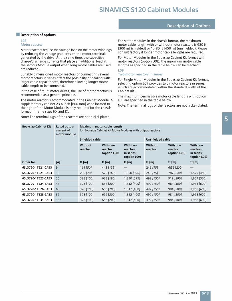
5
Siemens D21.7 – 2013 5/13
SINAMICS S120 Cabinet Modules
Description of Options
Description of options
L08Motor reactor
Motorreactorsreducethevoltageloadonthemotorwindingsbyreducingthevoltagegradientsonthemotorterminalsgeneratedbythedrive.Atthesametime,thecapacitivecharge/dischargecurrentsthatplaceanadditionalloadattheMotorsModuleoutputwhenlongmotorcablesareusedarereduced.
Suitablydimensionedmotorreactorsorconnectingseveralmotorreactorsinseriesoffersthepossibilityofdealingwithlargercablecapacitances,thereforeallowinglongermotorcablelengthtobeconnected.
Inthecaseofmultimotordrives,theuseofmotorreactorsisrecommendedasageneralprinciple.
ThemotorreactorisaccommodatedintheCabinetModule.Asupplementarycabinet23.6inch[600mm]widelocatedtotherightoftheMotorModuleisonlyrequiredforthechassisformatinframesizesHXandJX.
Note:Theterminallugsofthereactorsarenotnickel-plated.
ForMotorModulesinthechassisformat,themaximummotorcablelengthwithorwithoutmotorreactorsis980ft[300m](shielded)or1,480ft[450m](unshielded).Pleaseconsultfactoryiflongermotorcablelengthsarerequired.
ForMotorModulesintheBooksizeCabinetKitformatwithmotorreactors(optionL08),themaximummotorcablelengthsasspecifiedinthetablebelowcanbereached:
L09Two motor reactors in series
ForSingleMotorModulesintheBooksizeCabinetKitformat,selectingoptionL09providestwomotorreactorsinseries,whichareaccommodatedwithinthestandardwidthoftheCabinetKit.
ThemaximumpermissiblemotorcablelengthswithoptionL09arespecifiedinthetablebelow.
Note:Theterminallugsofthereactorsarenotnickel-plated.
Booksize Cabinet Kit Rated output current ofmotor module
Maximum motor cable lengthforBooksizeCabinetKitMotorModuleswithoutputreactors
Shielded cable Unshielded cable
Without reactor
With one reactor (option L08)
With two reactors in series (option L09)
Without reactor
With one reactor (option L08)
With two reactors in series (option L09)
Order No. [A] ft [m] ft [m] ft [m] ft [m] ft [m] ft [m]
6SL3720-1TE21-0AB3 9 164[50] 443[135] — 246[75] 6\56[200] —
6SL3720-1TE21-8AB3 18 230[70] 525[160] 1,050[320] 246[75] 787[240] 1,575[480]
6SL3720-1TE23-0AB3 30 328[100] 623[190] 1,230[375] 492[150] 919[280] 1,837[560]
6SL3720-1TE24-5AB3 45 328[100] 656[200] 1,312[400] 492[150] 984[300] 1,968[600]
6SL3720-1TE26-0AB3 60 328[100] 656[200] 1,312[400] 492[150] 984[300] 1,968[600]
6SL3720-1TE28-5AB3 85 328[100] 656[200] 1,312[400] 492[150] 984[300] 1,968[600]
6SL3720-1TE31-3AB3 132 328[100] 656[200] 1,312[400] 492[150] 984[300] 1,968[600]
5
5/14 Siemens D21.7 – 2013
SINAMICS S120 Cabinet Modules
Description of Options
Description of options
L10dV/dt filter with VPL (Voltage Peak Limiter)
ThedV/dtfilterplusVPL(VoltagePeakLimiter)limitsthevoltagerate-of-risedV/dttovalues<500V/ s,andthetypicalvoltagepeakstothefollowingvaluesaccordingtothelimitvaluecurvetoIEC/TS60034-17:2006:• <1000VatULine<575V• <1250Vat660V<ULine<690V
Thedv/dtfilterplusVPLfunctionallycomprisestwocomponents,thedv/dtreactorandthevoltagelimitingnetworkVPL,whichcutsoffvoltagepeaksandfeedsbacktheenergyintotheDCbus.OptionL10isinstalledinanadditionalcabinetwithawidthof23.6inch[600mm]thatislocatedontheright-handsideoftheMotorModule.
Adv/dtfilterplusVPLgenerallyallowstheuseofstandardnon-inverterdutymotorswithstandardinsulationandwith-outinsulatedbearingsforVFDoperation.
FormotorsinsulatedperNEMAMG1,part30(voltagepeaks<1,000VanddV/dt<500V/ s)themaximumallowablemotorcablelengthisasfollows.Withlongercablelengthsvoltagepeaksmayexceed1,000V.
Maximum motor cable length for motors insulated per NEMA MG1, part 30
Rated voltage Unshielded cable Shielded cable
380–480V 980’(300m) 980’(300m)
500–600V 490’(150m) 490’(150m)
ThedV/dtfilterplusVPLisdesignedforthefollowingmaximummotorcablelengths:• Shieldedcables: 980ft[300m]• Unshieldedcables 1,480ft[450m]
Whenusingdv/dtfilters,restrictionsregardingpermissiblepulseandoutputfrequenciesmustbeobserved.
PleaserefertotheappropriatenotesintheSINAMICSLowVoltageEngineeringManual.
Note:PartsofoptionL10donothavenickel-platedcopperbusbars.
OptionL10cannotbecombinedwiththefollowingoptions:• L07(dv/dtfiltercompactplusVPL)• L08(motorreactor).
L13Input contactor
LineConnectionModulesupto800Aratedinputcurrentincludeamanuallyoperatedmoldedcasecircuitbreaker(MCCB)disconnect.Theinputcontactorallowsthedrivetobeconnectedtoorbedisconnectedfromtheinputpowersupplyinresponsetoanelectricalcontrolsignal.Thisfunctionisalsorequiredtodisconnecttheline-upfromthesupplyintheeventofanEmergencyOFF(inthiscaseitiscontrolledbythedriveregulator).
AninputcontactoroptionL13isavailableforLineConnectionModuleswithBasicLineModules(optionL43);forSmartLineModulesandActiveLineModules,thecontactorisalreadyincludedforthepurposeofpre-charging.
L21 Line side surge arrestors for ungrounded supply systems
Threesinglephasesurgearrestorsareconnectedaheadoftheincomingcircuitbreakerdisconnect.
L22Without input line reactor
BasicLineModulesorSmartLineModulesaresuppliedasstandardwithlinereactors;thereasonforthisisthatalinereactorprimarilyassurestheminimumcurrentformfactor,protectsthedriveagainstexcessiveharmoniccurrentsandthusoverloads,andimprovesthesensitivityoftheVFDtovoltagespikes.Aninputlinereactorisrecommendedformostinstallations.
Ifthedriveispoweredviaaseparatedriveisolationtransformer,oriftheratiobetweenthelineshortcircuitcapacityatthepointofconnectionandtherateddriveoutputislow(highnetworkimpedance),theinputlinereactormaybeomittedbyselectingoptionL22.
OptionL22isavailableforLineConnectionModules(ratedcurrent<2000A)inconjunctionwithBasicLineModules(optionL43),aswellasforSmartLineModules.
ThisoptionisnotavailableforBasicorSmartLineModulesconnectedinparalleltoasingleLineConnectionModuleaslinereactorsarerequiredtoensurecurrentsharing.
Foradditionalinformation,pleaserefertotheSINAMICSLowVoltageEngineeringManual.
L25Drawout circuit breaker
LineConnectionModuleswithaninputcurrentof>800Aareequippedwithafixedmountedinsulatedcasecircuitbreakersasstandard.Ifthecustomerrequiresavisibleisolatingdistance,adrawoutcircuitbreakercanbeorderedasanoption.
5
Siemens D21.7 – 2013 5/15
SINAMICS S120 Cabinet Modules
Description of options
Description of Options
L34Output circuit breaker
AcircuitbreakerisprovidedattheoutputofMotorModuleschassisformat,todisconnectthemotorfromthedrive.
Apermanent-magnetsynchronousmotorgeneratesavoltageatitsmotorterminalsproportionaltothespeed,andintheeventofanoverspeedaveryhighvoltagecanbeappliedtotheoutputofthemotormodulewhichcandamagetotheinverteraswellastheDCbusandothercomponentsconnectedtoit.
TheoutputcircuitbreakeroptionL34isavailabletodisconnectthemotorintheeventofafaultorifmaintenanceworkistobecarriedout.OptionL34iscompletelyprewiredandisaccommodatedinanadditionalcabinet,whichisarrangedtotherighthandsideoftheMotorModule(16“[400mm]wideforframesizesFX/GX,23.6”[600mm]wideforframesizeHX/JX).
ThecircuitbreakerisautomaticallycontrolledbytheMotorModule.ATM31TerminalModuleisincludedwiththisoptiontoprovidetheassociatedinputsandoutputs.
OptionL34cannotbecombinedwithoptionL10(dv/dtfilterplusVoltagePeakLimiter).
L37DC disconnect including precharge circuit
If,forreasonsrelatingtotheprocessoravailability,theMotorModuleneedstobedisconnectedfromorconnectedtotheliveDCbusduringoperation,amanuallyoperateddisconnectswitchcanbeorderedasOptionL37.ForMotorModulesinthechassisformat,thistakestheformofamechanicallyoperateddisconnectswitch,andforBooksizeCabinetKitsanelectricallyoperatedcontactorcombination.
OptionL37isinstalledonthebusbarbetweentheMotorModuleandthemainDCbus.ToensurethatthemotormodulecanbeconnectedtoaliveDCbus,theoptionalsoincludesaprechargecircuitfortheDCcapacitorsoftherelevantMotorModule.
Theswitchingoperationisperformedexternally.Theoperatingleversarepadlockable(padlocknotincludedinscopeofdelivery).
OptionL37alsoincludesoptionM60(additionaltouchprotection)forchannelingthecoolingair.
OptionsL61/L62andL64/L65(brakingunits)cannotbeorderedtogetherwithoptionL37forspacereasons.
Note: Option L37 is not yet UL listed and cannot be included in a UL listed line-up.
L41 Current transformer upstream of main circuit breaker
Ifadditionalcurrenttransformersarerequiredformeasuringormonitoringpurposes,thesecanbeorderedasoptionL41fortheLineConnectionModules.Thecurrenttransformersareinstalledupstreamofthemaincircuitbreakerinallthreeinfeedphases.
Thetransformershaveanaccuracyclassof1.0.Thesecondarycurrentis5A,maximuminaNEMAversionLineConnectionModule(ordernumberendinginU3).
ThetransformermeasuringconnectionsareroutedtotheterminalblockintheLineConnectionModule.
Comment:ThesecurrenttransformersarealreadyincludedinoptionsP10andP11(powermeter).
L42Line Connection Module for Active Line Module
OptionL42addstherelevantcomponents(prechargeconnection,busbarsetc.)intheLineConnectionModuleforconnectiontoanActiveLineModule.Alsorefertothedescriptionsinsection3.
L43Line Connection Module for Basic Line Module
OptionL43addstherelevantcomponents(linereactor,prechargeconnection,busbarsetc.)intheLineConnectionModuleforconnectiontoaBasicLineModule.Alsorefertothedescriptionsinsection3.
L44Line Connection Module for Smart Line Module
OptionL44addstherelevantcomponents(prechargeconnection,busbarsetc.)intheLineConnectionModuleforconnectiontoaSmartLineModule.Alsorefertothedescriptionsinsection3.
L45EMERGENCY OFF pushbutton, installed in the cabinet door
Thetwist-to-release,padlockableEMERGENCYOFFpushbuttonisdoormountedintheLineConnectionModule,withitscontactswiredtoaterminalblock.Thisoptionisprovidedforintegrationintothecustomer’sexternalEMERGENCYOFFcircuit.
NOTE: This option is for a pushbutton only, it is not wired into the drive circuit.
L55Enclosure space heater
Spaceheatersarerecommendedatlowambienttemperaturesandhighlevelsofhumiditytopreventcondensation.One100WheaterisprovidedforeachCabinetModule<32”(800mm)wide.Forcabinetsexceedingthiswidth,twoheaterswillbeinstalled.Thisoptionrequiresanexternalpowersource(110to230V1phaseAC,fusedformax.16A).
OptionL55cannotbecombinedwithoptionK82(Terminalinterfaceforcontrollingsafetyfunctions).
L61, L62, L64, L65Braking units
Brakingunitsmayberequiredfordrivesinwhichmotorsmightoperateingeneratormodeandtheexcessenergycannotbeabsorbedbyotherloadsorregeneratedbackintothesupplysystem,orbrakingisrequiredifthesupplysystemfails.
Thebrakingunitcomprisestwocomponents:• ABrakingModulethatcanbeinstalledintheairdischarge ofchassisformatpowerunits• Abrakingresistortobemountedexternally(IP20degree ofprotection).
Thebrakingunitfunctionsasanautonomousunit,anddoesnotrequireanexternalpowersupply.Duringthebrakingprocess,thekineticenergyisconvertedintoheatintheexternallymountedbrakingresistor.
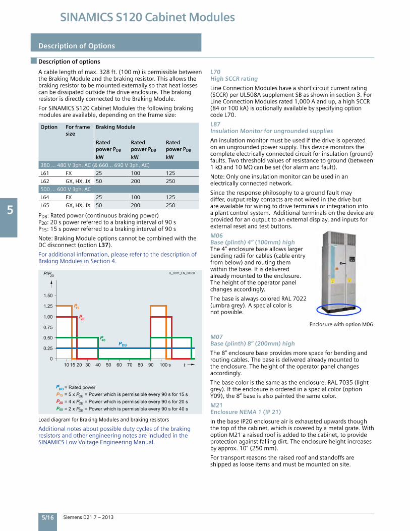
5
5/16 Siemens D21.7 – 2013
SINAMICS S120 Cabinet Modules
Description of Options
Description of options
Acablelengthofmax.328ft.(100m)ispermissiblebetweentheBrakingModuleandthebrakingresistor.Thisallowsthebrakingresistortobemountedexternallysothatheatlossescanbedissipatedoutsidethedriveenclosure.ThebrakingresistorisdirectlyconnectedtotheBrakingModule.
ForSINAMICSS120CabinetModulesthefollowingbrakingmodulesareavailable,dependingontheframesize:
PDB:Ratedpower(continuousbrakingpower)P20:20spowerreferredtoabrakingintervalof90sP15:15spowerreferredtoabrakingintervalof90s
Note:BrakingModuleoptionscannotbecombinedwiththeDCdisconnect(optionL37).
Foradditionalinformation,pleaserefertothedescriptionofBrakingModulesinSection4.
LoaddiagramforBrakingModulesandbrakingresistors
AdditionalnotesaboutpossibledutycyclesofthebrakingresistorsandotherengineeringnotesareincludedintheSINAMICSLowVoltageEngineeringManual.
L70High SCCR rating
LineConnectionModuleshaveashortcircuitcurrentrating(SCCR)perUL508AsupplementSBasshowninsection3.ForLineConnectionModulesrated1,000Aandup,ahighSCCR(84or100kA)isoptionallyavailablebyspecifyingoptioncodeL70.
L87Insulation Monitor for ungrounded supplies
Aninsulationmonitormustbeusedifthedriveisoperatedonanungroundedpowersupply.Thisdevicemonitorsthecompleteelectricallyconnectedcircuitforinsulation(ground)faults.Twothresholdvaluesofresistancetoground(between1k and10M canbeset(foralarmandfault).
Note:Onlyoneinsulationmonitorcanbeusedinanelectricallyconnectednetwork.
Sincetheresponsephilosophytoagroundfaultmaydiffer,outputrelaycontactsarenotwiredinthedrivebutareavailableforwiringtodriveterminalsorintegrationintoaplantcontrolsystem.Additionalterminalsonthedeviceareprovidedforanoutputtoanexternaldisplay,andinputsforexternalresetandtestbuttons.
M06Base (plinth) 4” (100mm) highThe4”enclosurebaseallowslargerbendingradiiforcables(cableentryfrombelow)androutingthemwithinthebase.Itisdeliveredalreadymountedtotheenclosure.Theheightoftheoperatorpanelchangesaccordingly.
ThebaseisalwayscoloredRAL7022(umbragrey).Aspecialcolorisnotpossible.
EnclosurewithoptionM06
M07Base (plinth) 8” (200mm) high
The8”enclosurebaseprovidesmorespaceforbendingandroutingcables.Thebaseisdeliveredalreadymountedtotheenclosure.Theheightoftheoperatorpanelchangesaccordingly.
Thebasecoloristhesameastheenclosure,RAL7035(lightgrey).Iftheenclosureisorderedinaspecialcolor(optionY09),the8”baseisalsopaintedthesamecolor.
M21Enclosure NEMA 1 (IP 21)
InthebaseIP20enclosureairisexhaustedupwardsthoughthetopofthecabinet,whichiscoveredbyametalgrate.WithoptionM21araisedroofisaddedtothecabinet,toprovideprotectionagainstfallingdirt.Theenclosureheightincreasesbyapprox.10”(250mm).
Fortransportreasonstheraisedroofandstandoffsareshippedaslooseitemsandmustbemountedonsite.
Option For frame size
Braking Module
Rated power PDB
Rated power PDB
Rated power PDB
kW kW kW
380…480V3ph.AC(&660…690V3ph.AC)
L61 FX 25 100 125
L62 GX,HX,JX 50 200 250
500…600V3ph.AC
L64 FX 25 100 125
L65 GX,HX,JX 50 200 250
15P
20P
40P
15P20P40P
15 s100908070605040302010 t
P/P20G_D011_EN_00328
= Rated power
DB
DB
DB
= 5 x P = Power which is permissible every 90 s for 15 s= 4 x P = Power which is permissible every 90 s for 20 s= 2 x P = Power which is permissible every 90 s for 40 s
DB
PDB
1.25
1.50
0.25
0
0.50
0.75
1.00
P
5
Siemens D21.7 – 2013 5/17
SINAMICS S120 Cabinet Modules
Description of options
Description of Options
M23Enclosure NEMA 1 filtered (IP23)
Atophatisaddedtotheenclosureincreasingitsheightbyapprox.16”(400mm).Louversandfoamairfiltersareaddedtoairinletandoutletopenings.OptionM23alsoincludesoptionM60(additionalcoversfortouchsafety).
ANEMA1filtered(IP23)enclosureistheminimumrequiredforlistingtheencloseddriveperUL508A.Fortransportreasonsthetophatisshippedasalooseitemandmustbemountedonsite.
Notethetophatwillbesuppliedinthesamecolorasthespecifiedfortheenclosure.However,themoldedplasticlouversarecoloredRAL7035andcannotbepainted.
M26Side panel mounted on right
CabinetModules(respectivelytransportsections)areopenatbothsides,forside-by-sideinstallationwithothercabinetmodules.WithoptionM26,thecabinetisfittedwithasidepanel(skin)ontheright(whenviewedfromthefront).
Note:Sidepanelsonbothsidesoftheline-uparenecessarytoobtaintheenclosuretype/degreeofprotectionspecified.
M27Side panel mounted on left
CabinetModules(respectivelytransportsections)areopenatbothsides,forside-by-sideinstallationwithothercabinetmodules.WithoptionM27,thecabinetisfittedwithasidepanel(skin)ontheleft(whenviewedfromthefront).
Note:Sidepanelsonbothsidesoftheline-uparenecessarytoobtaintheenclosuretype/degreeofprotectionspecified.
M43Enclosure IP43
SimilartoNEMA1filtered(M23)withtophatandfoamairfiltersonairinletsandoutlets,butadditionallya1mmwiremeshisprovidedbehindtheairfilters.
Thetophatincreasesthebaseenclosureheightbyapprox.16”(400mm).
Notethetophatwillbesuppliedinthesamecolorasthespecifiedfortheenclosure.However,themoldedplasticlouversarecoloredRAL7035andcannotbepainted.
M54Enclosure NEMA 12 ventilated (IP54)
SimilartoNEMA1filtered(M23)withtophatandlouversbutwithfinepaperairfiltersaddedtoairinletandoutletopenings,topreventevenfinedustparticlesfromenteringtheenclosureinverydustyenvironments.
Thesefinedustfiltersareapatenteddesignforhighvolumeairflowwithsmallderating.PleaserefertoEngineeringInformationsection6forcurrentderatingwithaNEMA12filteredenclosure.
Thetophatincreasesthebaseenclosureheightbyapprox.16”(400mm).
Notethetophatwillbesuppliedinthesamecolorasthespecifiedfortheenclosure.However,themoldedplasticlouversarecoloredRAL7035andcannotbepainted.
M59Closed cabinet doors, air inlet from below through floor
IftheCabinetModulesareinstalledonafalsefloororductwhichformspartofaforcedventilationsystem,themodulescanbeorderedwithcloseddoors(withoutventilationopenings).Toensureanadequateairinletcross-section,theunitsareshippedwithoutthestandardbaseplates.Inthiscase,thecustomermustensurethatdirt,dustormoisturecannotentertheCabinetModule.Cablesmustberoutedinsuchawaythattheydonotimpedetheflowofairthroughthecabinetflooropening.
SuitabletouchprotectionmustbeprovidediftheareabeneaththeCabinetModulescanbeaccessed.
M60Additional touch protection
WithoptionM60,additionalcoversareinstalledforimprovedtouchprotectionofliveparts,suchasintheareaoftheACandDCbusbarsandinfrontofthepowerunit.
OptionM60isalreadyincludedwithOptionsM23,M43andM54.
M70EMC shield bus
TheEMCshieldbusisusedfortheconnectionoftheshieldsofcablesonthelineandmotorsides.ThesuppliedEMCshieldclampsprovidealargesurfaceareafortheconnection,toensureeffectivegroundingalsoofhighfrequencynoise.
M80 to M87DC busbar system
ThebusbarsforthecommonDCbusarelocatedintheuppersectionoftheCabinetModules,andconnecttheLineModulestotheMotorModules.Theyarenickelplatedasstandardandareavailableindifferentsizesforarangeofcurrentcarryingcapacities.
ThecommonDCbusisdimensionedaccordingtotheloadrequirementsanddemandfactorassociatedwithoperationoftheindividualdrives,andaccordingtothespecificCabinetModulelayout.ForthisreasontheDCbusisnotsuppliedasstandard,butmustbespecifiedasanoptionforeachCabinetModule.Pleasealsorefertosection2–Systemconfigurationguidelines.
WhenselectingtheDCbus,itisimportanttoensurethatthebussizesinadjacentCabinetModulesarecompatiblewitheachother(refertothetablebelowandoptionselectionmatrixfortheCabinetModulesinquestion).
IfCabinetModulesareorderedinfactoryassembledtransportsectionswithoptionY11,allCabinetModulesinatransportsectionmusthaveidenticalbusbars.
NotethatitismandatoryforallLineModules,MotorModules(Chassisformat)andBooksizeBaseCabinetstoincludeaDCbusoption.
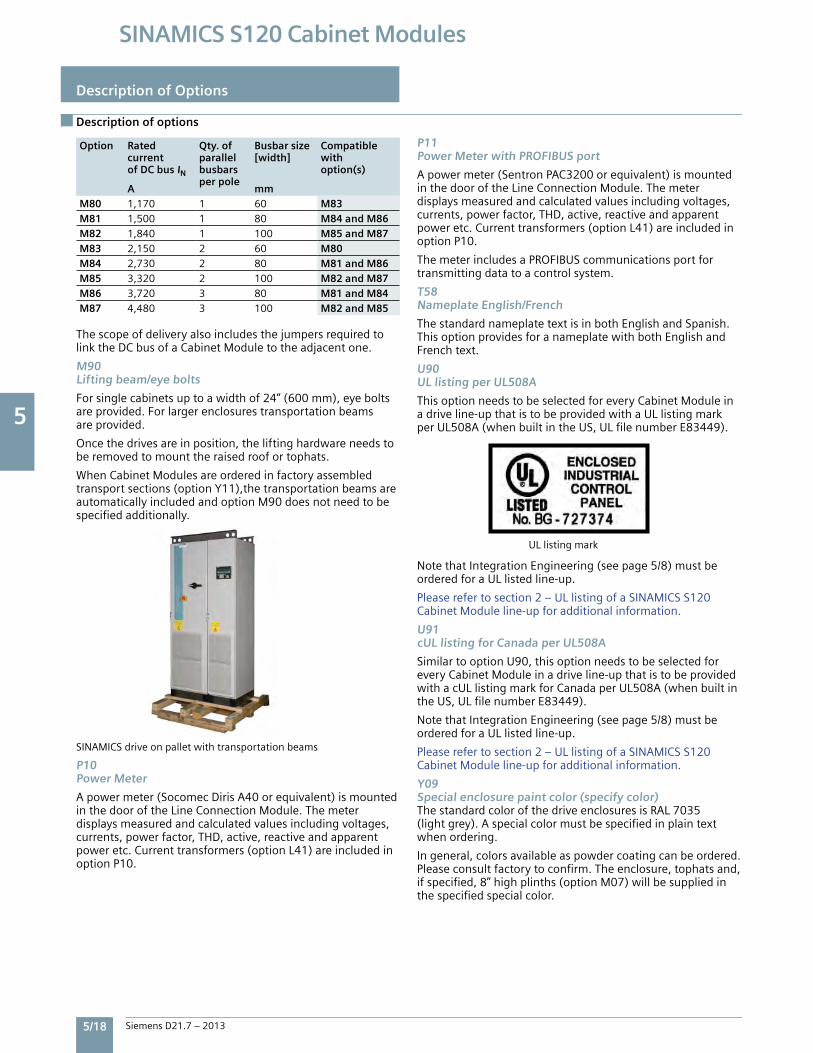
5
5/18 Siemens D21.7 – 2013
SINAMICS S120 Cabinet Modules
ThescopeofdeliveryalsoincludesthejumpersrequiredtolinktheDCbusofaCabinetModuletotheadjacentone.
M90Lifting beam/eye bolts
Forsinglecabinetsuptoawidthof24”(600mm),eyeboltsareprovided.Forlargerenclosurestransportationbeamsareprovided.
Oncethedrivesareinposition,theliftinghardwareneedstoberemovedtomounttheraisedroofortophats.
WhenCabinetModulesareorderedinfactoryassembledtransportsections(optionY11),thetransportationbeamsareautomaticallyincludedandoptionM90doesnotneedtobespecifiedadditionally.
SINAMICSdriveonpalletwithtransportationbeams
P10 Power Meter
Apowermeter(SocomecDirisA40orequivalent)ismountedinthedooroftheLineConnectionModule.Themeterdisplaysmeasuredandcalculatedvaluesincludingvoltages,currents,powerfactor,THD,active,reactiveandapparentpoweretc.Currenttransformers(optionL41)areincludedinoptionP10.
P11 Power Meter with PROFIBUS port
Apowermeter(SentronPAC3200orequivalent)ismountedinthedooroftheLineConnectionModule.Themeterdisplaysmeasuredandcalculatedvaluesincludingvoltages,currents,powerfactor,THD,active,reactiveandapparentpoweretc.Currenttransformers(optionL41)areincludedinoptionP10.
ThemeterincludesaPROFIBUScommunicationsportfortransmittingdatatoacontrolsystem.
T58Nameplate English/French
ThestandardnameplatetextisinbothEnglishandSpanish.ThisoptionprovidesforanameplatewithbothEnglishandFrenchtext.
U90UL listing per UL508A
ThisoptionneedstobeselectedforeveryCabinetModuleinadriveline-upthatistobeprovidedwithaULlistingmarkperUL508A(whenbuiltintheUS,ULfilenumberE83449).
ULlistingmark
NotethatIntegrationEngineering(seepage5/8)mustbeorderedforaULlistedline-up.
Pleaserefertosection2–ULlistingofaSINAMICSS120CabinetModuleline-upforadditionalinformation.
U91cUL listing for Canada per UL508A
SimilartooptionU90,thisoptionneedstobeselectedforeveryCabinetModuleinadriveline-upthatistobeprovidedwithacULlistingmarkforCanadaperUL508A(whenbuiltintheUS,ULfilenumberE83449).
NotethatIntegrationEngineering(seepage5/8)mustbeorderedforaULlistedline-up.
Pleaserefertosection2–ULlistingofaSINAMICSS120CabinetModuleline-upforadditionalinformation.
Y09Special enclosure paint color (specify color)ThestandardcolorofthedriveenclosuresisRAL7035(lightgrey).Aspecialcolormustbespecifiedinplaintextwhenordering.
Ingeneral,colorsavailableaspowdercoatingcanbeordered.Pleaseconsultfactorytoconfirm.Theenclosure,tophatsand,ifspecified,8”highplinths(optionM07)willbesuppliedinthespecifiedspecialcolor.
Description of options
Option Rated current of DC bus IN
Qty. of parallel busbars per pole
Busbar size [width]
Compatible with option(s)
A mmM80 1,170 1 60 M83 M81 1,500 1 80 M84 and M86 M82 1,840 1 100 M85 and M87 M83 2,150 2 60 M80 M84 2,730 2 80 M81 and M86 M85 3,320 2 100 M82 and M87 M86 3,720 3 80 M81 and M84 M87 4,480 3 100 M82 and M85
Description of Options
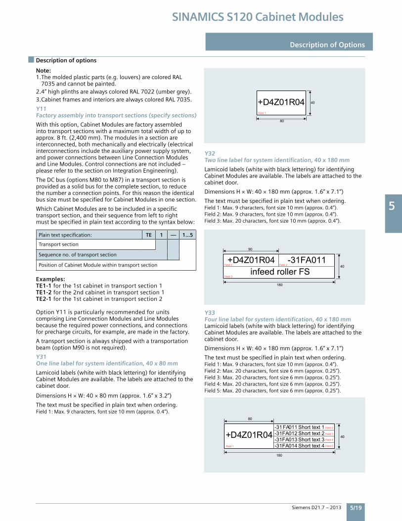
5
Siemens D21.7 – 2013 5/19
SINAMICS S120 Cabinet Modules
Description of options
Note: 1.Themoldedplasticparts(e.g.louvers)arecoloredRAL 7035andcannotbepainted.2.4”highplinthsarealwayscoloredRAL7022(umbergrey).3.CabinetframesandinteriorsarealwayscoloredRAL7035.
Y11Factory assembly into transport sections (specify sections)
Withthisoption,CabinetModulesarefactoryassembledintotransportsectionswithamaximumtotalwidthofuptoapprox.8ft.(2,400mm).Themodulesinasectionareinterconnected,bothmechanicallyandelectrically(electricalinterconnectionsincludetheauxiliarypowersupplysystem,andpowerconnectionsbetweenLineConnectionModulesandLineModules.Controlconnectionsarenotincluded–pleaserefertothesectiononIntegrationEngineering).
TheDCbus(optionsM80toM87)inatransportsectionisprovidedasasolidbusforthecompletesection,toreducethenumberaconnectionpoints.ForthisreasontheidenticalbussizemustbespecifiedforCabinetModulesinonesection.
WhichCabinetModulesaretobeincludedinaspecifictransportsection,andtheirsequencefromlefttorightmustbespecifiedinplaintextaccordingtothesyntaxbelow:
Plaintextspecification: TE 1 — 1...5
Transportsection
Sequenceno.oftransportsection
PositionofCabinetModulewithintransportsection
Examples:TE1-1forthe1stcabinetintransportsection1TE1-2forthe2ndcabinetintransportsection1TE2-1forthe1stcabinetintransportsection2
OptionY11isparticularlyrecommendedforunitscomprisingLineConnectionModulesandLineModulesbecausetherequiredpowerconnections,andconnectionsforprechargecircuits,forexample,aremadeinthefactory.
Atransportsectionisalwaysshippedwithatransportationbeam(optionM90isnotrequired).
Y31One line label for system identification, 40 x 80 mm
Lamicoidlabels(whitewithblacklettering)foridentifyingCabinetModulesareavailable.Thelabelsareattachedtothecabinetdoor.
DimensionsH×W:40×80mm(approx.1.6“x3.2“)
Thetextmustbespecifiedinplaintextwhenordering.Field1:Max.9characters,fontsize10mm(approx.0.4”).
Y32Two line label for system identification, 40 x 180 mm
Lamicoidlabels(whitewithblacklettering)foridentifyingCabinetModulesareavailable.Thelabelsareattachedtothecabinetdoor.
DimensionsH×W:40×180mm(approx.1.6“x7.1“)
Thetextmustbespecifiedinplaintextwhenordering.Field1:Max.9characters,fontsize10mm(approx.0.4”).Field2:Max.9characters,fontsize10mm(approx.0.4”).Field3:Max.20characters,fontsize10mm(approx.0.4”).
Y33Four line label for system identification, 40 x 180 mmLamicoidlabels(whitewithblacklettering)foridentifyingCabinetModulesareavailable.Thelabelsareattachedtothecabinetdoor.
DimensionsH×W:40×180mm(approx.1.6“x7.1“)
Thetextmustbespecifiedinplaintextwhenordering.Field1:Max.9characters,fontsize10mm(approx.0.4”).Field2:Max.20characters,fontsize6mm(approx.0.25”).Field3:Max.20characters,fontsize6mm(approx.0.25”).Field4:Max.20characters,fontsize6mm(approx.0.25”).Field5:Max.20characters,fontsize6mm(approx.0.25”).
Description of Options
1Field
40
80
04R01Z4D+
3Field
2Field 1Field
infeed roller FS
90
40
180
011FA31-04R01Z4D+
Field 5
Field 4
Field 3
Field 2
Field 1 Short text 4 014FA31-Short text 3 013FA31-Short text 2 012FA31-Short text 1 011 FA31-
04R01Z4D+
80
40
180
5
5/20 Siemens D21.7 – 2013
SINAMICS S120 Cabinet Modules
Notes
5
SINAMICS S120 Cabinet ModulesEngineering Information
6/2 Technical data Electricalandmechanicalspecifications Ambientconditions Mechanicalstability Compliancewithstandards
6/5 Characteristic curves Deratingduetoaltitudeandtemperature Deratingasafunctionofpulsefrequency Overloadcapability
6/8 Control units and interfaces CU320-2DPControlUnit CU320-2PNControlUnit SINAMICSS120firmware CBE20CommunicationsboardEthernet BOP20BasicOperatorPanel AOP30BasicOperatorPanel CustomerTerminalBlock–X55
6/19 Sensor and I/O modules SMC10SensorModule SMC20SensorModule SMC30SensorModule TM150Terminal(RTD)Module VSM10VoltageSensingModule
6/24 Connection system – Signal cables DRIVE-CLIQcables
6/28 Safety Integrated SafetyIntegratedFunctions TM54FTerminalModule,FailSafe SBASafeBrakeAdapter
6
SiemensD21.7–2013
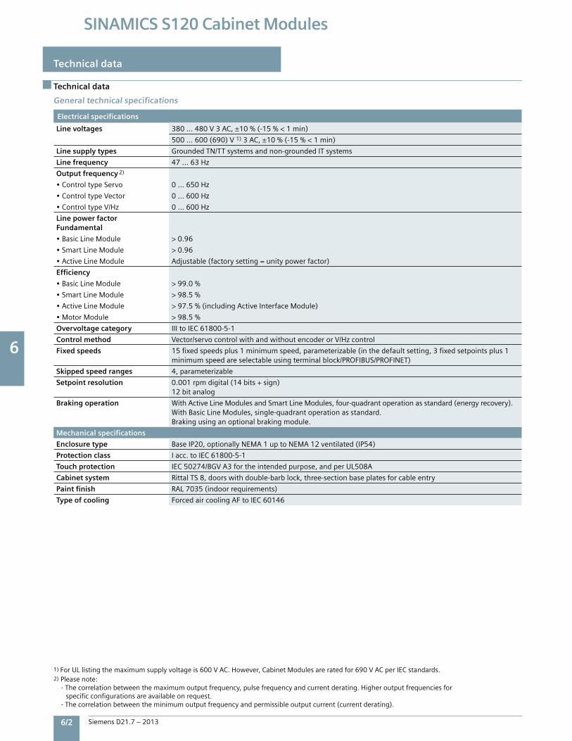
6 6
6/2 Siemens D21.7 – 2013
SINAMICS S120 Cabinet Modules
Technical data
Technical data
Electrical specifications
Line voltages 380…480V3AC,±10%(-15%<1min)
500…600(690)V1)3AC,±10%(-15%<1min)
Line supply types GroundedTN/TTsystemsandnon-groundedITsystems
Line frequency 47…63Hz
Output frequency 2)
•ControltypeServo 0…650Hz
•ControltypeVector 0…600Hz
•ControltypeV/Hz 0…600Hz
Line power factorFundamental
•BasicLineModule >0.96
•SmartLineModule >0.96
•ActiveLineModule Adjustable(factorysetting=unitypowerfactor)
Efficiency
•BasicLineModule >99.0%
•SmartLineModule >98.5%
•ActiveLineModule >97.5%(includingActiveInterfaceModule)
•MotorModule >98.5%
Overvoltage category IIItoIEC61800-5-1
Control method Vector/servocontrolwithandwithoutencoderorV/Hzcontrol
Fixed speeds 15fixedspeedsplus1minimumspeed,parameterizable(inthedefaultsetting,3fixedsetpointsplus1minimumspeedareselectableusingterminalblock/PROFIBUS/PROFINET)
Skipped speed ranges 4,parameterizable
Setpoint resolution 0.001rpmdigital(14bits+sign)12bitanalog
Braking operation WithActiveLineModulesandSmartLineModules,four-quadrantoperationasstandard(energyrecovery).WithBasicLineModules,single-quadrantoperationasstandard.Brakingusinganoptionalbrakingmodule.
Mechanical specifications
Enclosure type BaseIP20,optionallyNEMA1uptoNEMA12ventilated(IP54)
Protection class Iacc.toIEC61800-5-1
Touch protection IEC50274/BGVA3fortheintendedpurpose,andperUL508A
Cabinet system RittalTS8,doorswithdouble-barblock,three-sectionbaseplatesforcableentry
Paint finish RAL7035(indoorrequirements)
Type of cooling ForcedaircoolingAFtoIEC60146
General technical specifications
1)ForULlistingthemaximumsupplyvoltageis600VAC.However,CabinetModulesareratedfor690VACperIECstandards.2)Pleasenote: -Thecorrelationbetweenthemaximumoutputfrequency,pulsefrequencyandcurrentderating.Higheroutputfrequenciesforspecificconfigurationsareavailableonrequest. -Thecorrelationbetweentheminimumoutputfrequencyandpermissibleoutputcurrent(currentderating).

6 6
Siemens D21.7 – 2013 6/3
SINAMICS S120 Cabinet Modules
Technical data
Technical data
1) In transport packaging.2) Deviations with respect to the specified class are underlined.
Ambient conditions Storage 1) Transport 1) Operation
Ambient temperature -13 ... 131 °F (-25 ... +55 °C) -13 ... 158 °F (-25 ... +70 °C)down to -40 °F (-40 °C) 2) for 24 hours
32 ... +104 °F (0 ... +40 °C)to +122 °F (+50 °C) see derating data
Relative humidity(condensation not permissible)
5 ... 95% 2)
acc. to IEC 60721-3-15 ... 95% at 40 °CClass 2K3 acc. to IEC 60721-3-2
5 ... 95% 2)
Class 3K3 acc. to IEC 60721-3-3
Environmental class/harmfulchemical substances
Class 1C2acc. to IEC 60721-3-1
Class 2C2acc. to IEC 60721-3-2
Class 3C2acc. to IEC 60721-3-3
Organic/biological influences Class 1B1acc. to IEC 60721-3-1
Class 2B1acc. to IEC 60721-3-2
Class 3B1acc. to IEC 60721-3-3
Degree of pollution Class 2 acc. to IEC 61800-5-1 Class 2 acc. to IEC 61800-5-1 Class 2 acc. to IEC 61800-5-1
Installation altitude Cabinet Modules, chassis format:up to 2000 m above sea level, without derating, > 2000 m, see characteristic curves/derating dataFor Motor Modules Booksize Cabinet Kit format:up to 1000 m above sea level without derating, > 1000 m, see characteristic curves/derating data
Mechanical stability Storage 1) Transport 1) Operation
Vibration load Class 1M2acc. to IEC 60721-3-1
Class 2M2acc. to IEC 60721-3-2
—
• Deflection 1.5 mm at 5 ... 9 Hz 3.1 mm at 5 ... 9 Hz 0.075 mm at 10 ... 58 Hz
• Acceleration 5 m/s² at > 9 ... 200 Hz 10 m/s² at > 9 ... 200 Hz 9.8 m/s² at > 58 ... 200 Hz
Shock load Class 1M2acc. to IEC 60721-3-1
Class 2M2acc. to IEC 60721-3-2
Class 3M4acc. to IEC 60721-3-3
• Acceleration 40 m/s² at 22 ms 100 m/s² at 11 ms 100 m/s² at 11 ms
Compliance with standards
Conformances/approvals,according to
CE (EMC Directive No. 2004/108/EC and Low-Voltage Directive No. 2006/95/EC). Optional UL listing to UL508A.
Radio interferencesuppression
SINAMICS drive systems are not designed for connection to the public network (first environment). Radio interference suppression is compliant with the EMC product standard for variable speed drives IEC 61800-3, “Second environment” (industrial line supplies). The equipment can cause electromagnetic interference when it is connected to the public network.
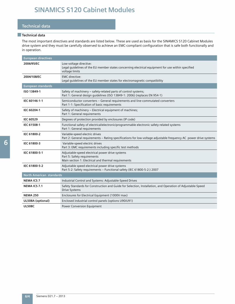
6 6
6/4 Siemens D21.7 – 2013
SINAMICS S120 Cabinet Modules
Technical data
Technical data
Themostimportantdirectivesandstandardsarelistedbelow.TheseareusedasbasisfortheSINAMICSS120CabinetModulesdrivesystemandtheymustbecarefullyobservedtoachieveanEMC-compliantconfigurationthatissafebothfunctionallyandinoperation.
European directives
2006/95/EC Low-voltagedirective:LegalguidelinesoftheEUmemberstatesconcerningelectricalequipmentforusewithinspecifiedvoltagelimits
2004/108/EC EMCdirective:LegalguidelinesoftheEUmemberstatesforelectromagneticcompatibility
European standards
ISO 13849-1 Safetyofmachinery–safety-relatedpartsofcontrolsystems;Part1:Generaldesignguidelines(ISO13849-1:2006)(replacesEN954-1)
IEC 60146-1-1 Semiconductorconverters–Generalrequirementsandline-commutatedconvertersPart1-1:Specificationofbasicrequirements
IEC 60204-1 Safetyofmachinery–Electricalequipmentofmachines;Part1:Generalrequirements
IEC 60529 Degreesofprotectionprovidedbyenclosures(IPcode)
IEC 61508-1 Functionalsafetyofelectrical/electronic/programmableelectronicsafety-relatedsystemsPart1:Generalrequirements
IEC 61800-2 Variable-speedelectricdrivesPart2:Generalrequirements–Ratingspecificationsforlow-voltageadjustablefrequencyACpowerdrivesystems
IEC 61800-3 Variable-speedelectricdrivesPart3:EMCrequirementsincludingspecifictestmethods
IEC 61800-5-1 Adjustable-speedelectricalpowerdrivesystemsPart5:SafetyrequirementsMainsection1:Electricalandthermalrequirements
IEC 61800-5-2 AdjustablespeedelectricalpowerdrivesystemsPart5-2:Safetyrequirements–Functionalsafety(IEC61800-5-2:)2007
North American standards
NEMA ICS 7 IndustrialControlandSystems:Adjustable-SpeedDrives
NEMA ICS 7.1 SafetyStandardsforConstructionandGuideforSelection,Installation,andOperationofAdjustable-SpeedDriveSystems
NEMA 250 EnclosuresforElectricalEquipment(1000Vmax)
UL508A (optional) Enclosedindustrialcontrolpanels(optionsU90/U91)
UL508C PowerConversionEquipment
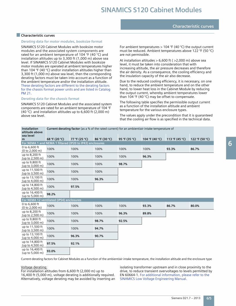
6 6
Siemens D21.7 – 2013 6/5
SINAMICS S120 Cabinet Modules
Characteristic curves
Characteristic curves
Voltage derating:For installation altitudes from 6,600 ft (2,000 m) up to 16,400 ft (5,000 m), voltage derating is additionally required. Alternatively, voltage derating may be avoided by inserting an
isolating transformer upstream and in close proximity to the drive, to reduce transient overvoltages to levels permitted by EN 60664-1. For additional information, please refer to the SINAMICS Low Voltage Engineering Manual.
Derating data for motor modules, booksize format
SINAMICS S120 Cabinet Modules with booksize motor modules and the associated system components are rated for an ambient temperature of 104 °F (40 °C) and installation altitudes up to 3,300 ft (1,000 m) above sea level. If SINAMICS S120 Cabinet Modules with booksize motor modules are operated at ambient temperatures higher than 104 °F (40 °C) and/or installation altitudes higher than 3,300 ft (1,000 m) above sea level, then the corresponding derating factors must be taken into account as a function of the ambient temperature and/or the installation altitude. These derating factors are different to the derating factors for the chassis format power units and are listed in Catalog PM 21.
Derating data for the chassis format
SINAMICS S120 Cabinet Modules and the associated systemcomponents are rated for an ambient temperature of 104 °F (40 °C) and installation altitudes up to 6,600 ft (2,000 m) above sea level.
For ambient temperatures > 104 °F (40 °C) the output current must be reduced. Ambient temperatures above 122 °F (50 °C)are not permissible.
At installation altitudes > 6,600 ft ( >2,000 m) above sea level, it must be taken into consideration that with increasing altitude, the air pressure decreases and therefore the air density. As a consequence, the cooling efficiency and the insulation capacity of the air also decrease.
Due to the reduced cooling efficiency, it is necessary, on onehand, to reduce the ambient temperature and on the other hand, to lower heat loss in the Cabinet Module by reducing the output current, whereby ambient temperatures lower than 104 °F (40 °C) may be offset to compensate.
The following table specifies the permissible output current as a function of the installation altitude and ambient temperature for the various enclosure types.
The values apply under the precondition that it is guaranteed that the cooling air flow is as specified in the technical data.
Installation altitude abovesea levelm
Current derating factor (as a % of the rated current) for an ambient/air intake temperature of
68 °F (20 °C) 77 °F (25 °C) 86 °F (30 °C) 95 °F (35 °C) 104 °F (40 °C) 113 °F (45 °C) 122 °F (50 °C)For NEMA 1 and NEMA 1 filtered (IP20 to IP43) enclosures0 to 6,600 ft (0 to 2,000 m) 100% 100% 100% 100% 100% 93.3% 86.7%
up to 8,200 ft (up to 2,500 m) 100% 100% 100% 100% 96.3%
up to 9,800 ft (up to 3,000 m) 100% 100% 100% 98.7%
up to 11,500 ft (up to 3,500 m) 100% 100% 100%
up to 13,100 ft (up to 4,000 m) 100% 100% 96.3%
up to 14,800 ft (up to 4,500 m) 100% 97.5%
up to 16,400 ft (up to 5,000 m) 98.2%
For NEMA 12 ventilated (IP54) enclosures0 to 6,600 ft (0 to 2,000 m) 100% 100% 100% 100% 93.3% 86.7% 80.0%
up to 8,200 ft (up to 2,500 m) 100% 100% 100% 96.3% 89.8%
up to 9,800 ft (up to 3,000 m) 100% 100% 98.7% 92.5%
up to 11,500 ft (up to 3,500 m) 100% 100% 94.7%
up to 13,100 ft (up to 4,000 m) 100% 96.3% 90.7%
up to 14,800 ft (up to 4,500 m) 97.5% 92.1%
up to 16,400 ft (up to 5,000 m) 93.0%
Current-derating factors for Cabinet Modules as a function of the ambient/air intake temperature, the installation altitude and the enclosure type
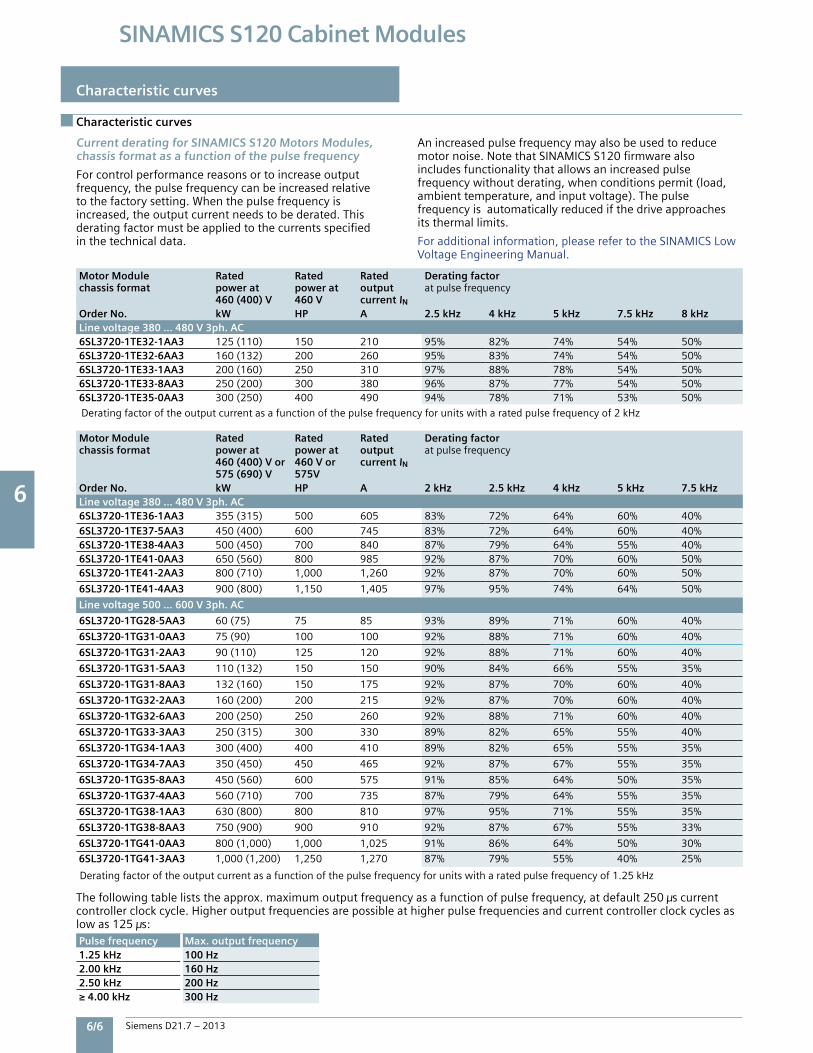
6 6
6/6 Siemens D21.7 – 2013
SINAMICS S120 Cabinet Modules
Characteristic curves
Characteristic curves
Current derating for SINAMICS S120 Motors Modules, chassis format as a function of the pulse frequency
Forcontrolperformancereasonsortoincreaseoutputfrequency,thepulsefrequencycanbeincreasedrelativetothefactorysetting.Whenthepulsefrequencyisincreased,theoutputcurrentneedstobederated.Thisderatingfactormustbeappliedtothecurrentsspecifiedinthetechnicaldata.
Anincreasedpulsefrequencymayalsobeusedtoreducemotornoise.NotethatSINAMICSS120firmwarealsoincludesfunctionalitythatallowsanincreasedpulsefrequencywithoutderating,whenconditionspermit(load,ambienttemperature,andinputvoltage).Thepulsefrequencyisautomaticallyreducedifthedriveapproachesitsthermallimits.
Foradditionalinformation,pleaserefertotheSINAMICSLowVoltageEngineeringManual.
Motor Modulechassis format
Ratedpower at460 (400) V
Ratedpower at460 V
Ratedoutputcurrent IN
Derating factoratpulsefrequency
Order No. kW HP A 2.5 kHz 4 kHz 5 kHz 7.5 kHz 8 kHzLine voltage 380 … 480 V 3ph. AC6SL3720-1TE32-1AA3 125(110) 150 210 95% 82% 74% 54% 50%6SL3720-1TE32-6AA3 160(132) 200 260 95% 83% 74% 54% 50%6SL3720-1TE33-1AA3 200(160) 250 310 97% 88% 78% 54% 50%6SL3720-1TE33-8AA3 250(200) 300 380 96% 87% 77% 54% 50%6SL3720-1TE35-0AA3 300(250) 400 490 94% 78% 71% 53% 50%
Deratingfactoroftheoutputcurrentasafunctionofthepulsefrequencyforunitswitharatedpulsefrequencyof2kHz
Motor Modulechassis format
Ratedpower at460 (400) V or575 (690) V
Ratedpower at460 V or575V
Ratedoutputcurrent IN
Derating factoratpulsefrequency
Order No. kW HP A 2 kHz 2.5 kHz 4 kHz 5 kHz 7.5 kHzLine voltage 380 … 480 V 3ph. AC6SL3720-1TE36-1AA3 355(315) 500 605 83% 72% 64% 60% 40%6SL3720-1TE37-5AA3 450(400) 600 745 83% 72% 64% 60% 40%6SL3720-1TE38-4AA3 500(450) 700 840 87% 79% 64% 55% 40%6SL3720-1TE41-0AA3 650(560) 800 985 92% 87% 70% 60% 50%6SL3720-1TE41-2AA3 800(710) 1,000 1,260 92% 87% 70% 60% 50%
6SL3720-1TE41-4AA3 900(800) 1,150 1,405 97% 95% 74% 64% 50%
Line voltage 500 … 600 V 3ph. AC
6SL3720-1TG28-5AA3 60(75) 75 85 93% 89% 71% 60% 40%
6SL3720-1TG31-0AA3 75(90) 100 100 92% 88% 71% 60% 40%
6SL3720-1TG31-2AA3 90(110) 125 120 92% 88% 71% 60% 40%
6SL3720-1TG31-5AA3 110(132) 150 150 90% 84% 66% 55% 35%
6SL3720-1TG31-8AA3 132(160) 150 175 92% 87% 70% 60% 40%
6SL3720-1TG32-2AA3 160(200) 200 215 92% 87% 70% 60% 40%
6SL3720-1TG32-6AA3 200(250) 250 260 92% 88% 71% 60% 40%
6SL3720-1TG33-3AA3 250(315) 300 330 89% 82% 65% 55% 40%
6SL3720-1TG34-1AA3 300(400) 400 410 89% 82% 65% 55% 35%
6SL3720-1TG34-7AA3 350(450) 450 465 92% 87% 67% 55% 35%
6SL3720-1TG35-8AA3 450(560) 600 575 91% 85% 64% 50% 35%
6SL3720-1TG37-4AA3 560(710) 700 735 87% 79% 64% 55% 35%
6SL3720-1TG38-1AA3 630(800) 800 810 97% 95% 71% 55% 35%
6SL3720-1TG38-8AA3 750(900) 900 910 92% 87% 67% 55% 33%
6SL3720-1TG41-0AA3 800(1,000) 1,000 1,025 91% 86% 64% 50% 30%
6SL3720-1TG41-3AA3 1,000(1,200) 1,250 1,270 87% 79% 55% 40% 25%
Deratingfactoroftheoutputcurrentasafunctionofthepulsefrequencyforunitswitharatedpulsefrequencyof1.25kHz
Thefollowingtableliststheapprox.maximumoutputfrequencyasafunctionofpulsefrequency,atdefault250 scurrentcontrollerclockcycle.Higheroutputfrequenciesarepossibleathigherpulsefrequenciesandcurrentcontrollerclockcyclesaslowas125 s:Pulse frequency Max. output frequency1.25 kHz 100 Hz2.00 kHz 160 Hz2.50 kHz 200 Hz≥ 4.00 kHz 300 Hz
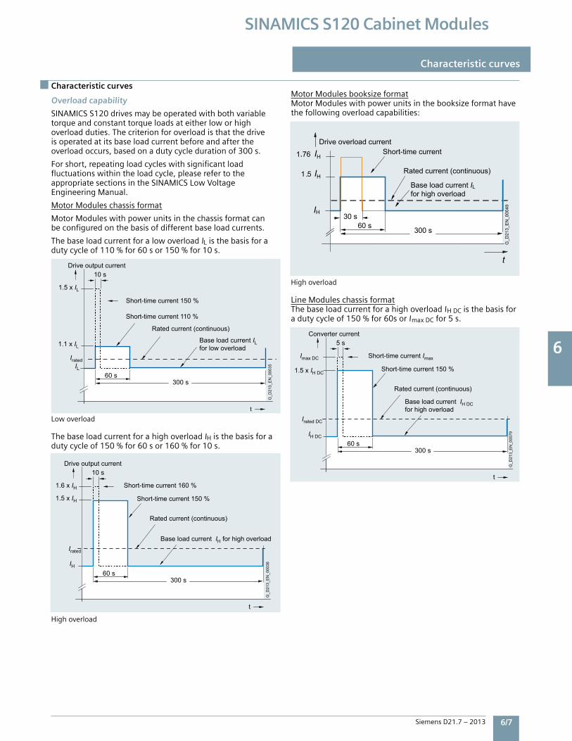
6 6
Siemens D21.7 – 2013 6/7
SINAMICS S120 Cabinet Modules
Characteristic curves
Characteristic curves
60 s
5 s
t
300 s
Irated DC
IH DC
Base load current IH DC for high overload
G_D
213_
EN
_000
79
Converter current
Rated current (continuous)
Short-time current 150 %
Short-time current Imax Imax DC
1.5 x IH DC60 s
10 s
300 s
t
1.1 x IL
1.5 x IL
Short-time current 110 %
Short-time current 150 %
Rated current (continuous)
Drive output currentG
_D21
3_E
N_0
0035
Base load current IL for low overload
ILIrated
60 s
10 s
t
1.5 x IH
1.6 x IH Short-time current 160 %
Short-time current 150 %
Rated current (continuous)
Drive output current
G_D
213_
EN
_000
36
Base load current IH for high overload
IH
Irated
300 s
G_D
213_
EN
_000
49
HI76 .1
30 s
for high overloadBase load current IL
HI
HI5 .1
Drive overload currentShort-time current
Rated current (continuous)
t
300 s 60 s
Overload capability
SINAMICSS120drivesmaybeoperatedwithbothvariabletorqueandconstanttorqueloadsateitherloworhighoverloadduties.Thecriterionforoverloadisthatthedriveisoperatedatitsbaseloadcurrentbeforeandaftertheoverloadoccurs,basedonadutycycledurationof300s.
Forshort,repeatingloadcycleswithsignificantloadfluctuationswithintheloadcycle,pleaserefertotheappropriatesectionsintheSINAMICSLowVoltageEngineeringManual.
MotorModuleschassisformat
MotorModuleswithpowerunitsinthechassisformatcanbeconfiguredonthebasisofdifferentbaseloadcurrents.
ThebaseloadcurrentforalowoverloadIListhebasisforadutycycleof110%for60sor150%for10s.
Lowoverload
ThebaseloadcurrentforahighoverloadIHisthebasisforadutycycleof150%for60sor160%for10s.
Highoverload
MotorModulesbooksizeformatMotorModuleswithpowerunitsinthebooksizeformathavethefollowingoverloadcapabilities:
Highoverload
LineModuleschassisformatThebaseloadcurrentforahighoverloadIHDCisthebasisforadutycycleof150%for60sorImaxDCfor5s.
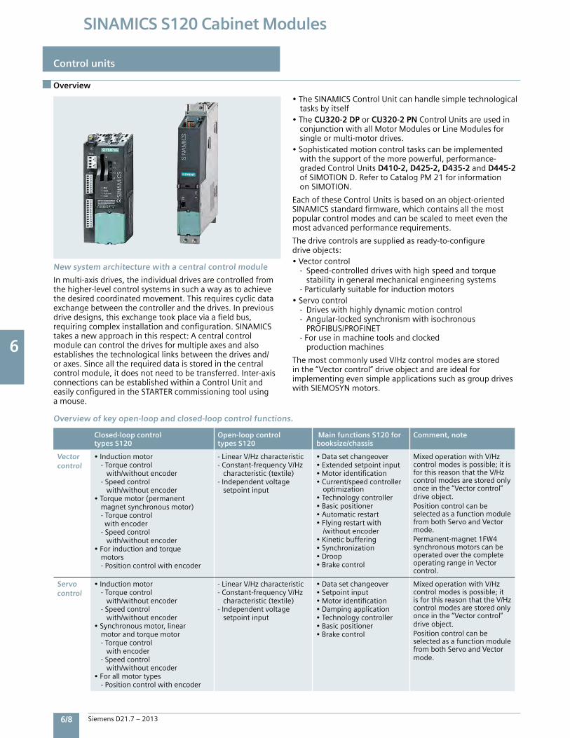
6 6
6/8 Siemens D21.7 – 2013
SINAMICS S120 Cabinet Modules
Control units
Overview
New system architecture with a central control module
Inmulti-axisdrives,theindividualdrivesarecontrolledfromthehigher-levelcontrolsystemsinsuchawayastoachievethedesiredcoordinatedmovement.Thisrequirescyclicdataexchangebetweenthecontrollerandthedrives.Inpreviousdrivedesigns,thisexchangetookplaceviaafieldbus,requiringcomplexinstallationandconfiguration.SINAMICStakesanewapproachinthisrespect:Acentralcontrolmodulecancontrolthedrivesformultipleaxesandalsoestablishesthetechnologicallinksbetweenthedrivesand/oraxes.Sincealltherequireddataisstoredinthecentralcontrolmodule,itdoesnotneedtobetransferred.Inter-axisconnectionscanbeestablishedwithinaControlUnitandeasilyconfiguredintheSTARTERcommissioningtoolusingamouse.
•TheSINAMICSControlUnitcanhandlesimpletechnological tasksbyitself•The CU320-2 DP orCU320-2 PN ControlUnitsareusedin conjunctionwithallMotorModulesorLineModulesfor singleormulti-motordrives.•Sophisticatedmotioncontroltaskscanbeimplemented withthesupportofthemorepowerful,performance- gradedControlUnitsD410-2, D425-2, D435-2 andD445-2 ofSIMOTIOND.RefertoCatalogPM21forinformation onSIMOTION.
EachoftheseControlUnitsisbasedonanobject-orientedSINAMICSstandardfirmware,whichcontainsallthemostpopularcontrolmodesandcanbescaledtomeeteventhemostadvancedperformancerequirements.
Thedrivecontrolsaresuppliedasready-to-configuredriveobjects:•Vectorcontrol -Speed-controlleddriveswithhighspeedandtorque stabilityingeneralmechanicalengineeringsystems -Particularlysuitableforinductionmotors•Servocontrol -Driveswithhighlydynamicmotioncontrol -Angular-lockedsynchronismwithisochronous PROFIBUS/PROFINET -Foruseinmachinetoolsandclocked productionmachines
ThemostcommonlyusedV/Hzcontrolmodesarestoredinthe“Vectorcontrol”driveobjectandareidealforimplementingevensimpleapplicationssuchasgroupdriveswithSIEMOSYNmotors.
Closed-loop control types S120
Open-loop control types S120
Main functions S120 forbooksize/chassis
Comment, note
Vectorcontrol
•Inductionmotor -Torquecontrol with/withoutencoder -Speedcontrol with/withoutencoder•Torquemotor(permanent magnetsynchronousmotor) -Torquecontrol withencoder -Speedcontrol with/withoutencoder•Forinductionandtorque motors -Positioncontrolwithencoder
-LinearV/Hzcharacteristic-Constant-frequencyV/Hz characteristic(textile)-Independentvoltage setpointinput
•Datasetchangeover•Extendedsetpointinput•Motoridentification•Current/speedcontroller optimization•Technologycontroller•Basicpositioner•Automaticrestart•Flyingrestartwith /withoutencoder•Kineticbuffering•Synchronization•Droop•Brakecontrol
MixedoperationwithV/Hzcontrolmodesispossible;itisforthisreasonthattheV/Hzcontrolmodesarestoredonlyonceinthe“Vectorcontrol”driveobject.PositioncontrolcanbeselectedasafunctionmodulefrombothServoandVectormode.Permanent-magnet1FW4synchronousmotorscanbeoperatedoverthecompleteoperatingrangeinVectorcontrol.
Servo control
•Inductionmotor -Torquecontrol with/withoutencoder -Speedcontrol with/withoutencoder•Synchronousmotor,linear motorandtorquemotor -Torquecontrol withencoder -Speedcontrol with/withoutencoder•Forallmotortypes -Positioncontrolwithencoder
-LinearV/Hzcharacteristic-Constant-frequencyV/Hz characteristic(textile)-Independentvoltage setpointinput
•Datasetchangeover•Setpointinput•Motoridentification•Dampingapplication•Technologycontroller•Basicpositioner•Brakecontrol
MixedoperationwithV/Hzcontrolmodesispossible;itisforthisreasonthattheV/Hzcontrolmodesarestoredonlyonceinthe“Vectorcontrol”driveobject.PositioncontrolcanbeselectedasafunctionmodulefrombothServoandVectormode.
Overview of key open-loop and closed-loop control functions.
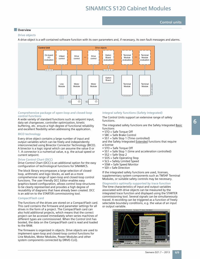
6 6
Siemens D21.7 – 2013 6/9
SINAMICS S120 Cabinet Modules
Overview
Control units
Drive objects
Adriveobjectisaself-containedsoftwarefunctionwithitsownparametersand,ifnecessary,itsownfaultmessagesandalarms.
G_D
211_
EN
_000
57a
Infeedcontrol
Drivecontrol
Drivecontrol
TerminalModule
evaluation
TerminalModule
evaluation
OptionBoard
evaluation
On-boardI/O
evaluation
Drive objectsControl Unit
TerminalModule
TerminalModule
MotorModule
MotorModule
LineModule
OptionBoard
......
Comprehensive package of open-loop and closed-loopcontrol functionsAwidevarietyofstandardfunctionssuchassetpointinput,datasetchangeover,controlleroptimization,kineticbuffering,etc.ensureahighdegreeoffunctionalreliabilityandexcellentflexibilitywhenaddressingtheapplication.
BICO technology
EverydriveobjectcontainsalargenumberofinputandoutputvariableswhichcanbefreelyandindependentlyinterconnectedusingBinectorConnectorTechnology(BICO).Abinectorisalogicsignalwhichcanassumethevalue0or1.Aconnectorisanumericalvalue,e.g.theactualspeedorcurrentsetpoint.
Drive Control Chart (DCC)DriveControlChart(DCC)isanadditionaloptionfortheeasyconfigurationoftechnologicalfunctionsforSINAMICS.
Theblocklibraryencompassesalargeselectionofclosed-loop,arithmeticandlogicblocks,aswellasamorecomprehensiverangeofopen-loopandclosed-loopcontrolfunctions.TheuserfriendlyDCCEditorenableseasygraphics-basedconfiguration,allowscontrolloopstructurestobeclearlyrepresentedandprovidesahighdegreeofreusabilityofdiagramsthathavealreadybeencreated.DCCisanadd-ontotheSTARTERcommissioningtool.
CompactFlash card
ThefunctionsofthedrivesarestoredonaCompactFlashcard.Thiscardcontainsthefirmwareandparametersettingsforalldrivesintheformofaproject.TheCompactFlashcardcanalsoholdadditionalprojects,whichmeansthatthecorrectprojectcanbeaccessedimmediatelywhenseriesmachinesofdifferenttypesarecommissioned.WhentheControlUnithasbooted,thedataontheCompactFlashcardisreadandloadedtotheRAM.
Thefirmwareisorganizedinobjects.Driveobjectsareusedtoimplementopen-loopandclosed-loopcontrolfunctionsforLineModules,MotorModules,PowerModulesandothersystemcomponentsconnectedbyDRIVE-CLiQ.
Integral safety functions (Safety Integrated)
TheControlUnitssupportanextensiverangeofsafetyfunctions.
TheintegratedsafetyfunctionsaretheSafetyIntegratedBasicfunctions•STO=SafeTorqueOff•SBC=SafeBrakeControl•SS1=SafeStop1(Timecontrolled)andtheSafetyIntegratedExtendedfunctionsthatrequirealicense•STO=SafeTorqueOff•SS1=SafeStop1(timeandaccelerationcontrolled)•SS2=SafeStop2•SOS=SafeOperatingStop•SLS=SafelyLimitedSpeed•SSM=SafeSpeedMonitor•SDI=SafeDirection
Iftheintegratedsafetyfunctionsareused,licenses,supplementarysystemcomponentssuchasTM54FTerminalModules,orsuitablesafetycontrolsmaybenecessary.
Diagnostics optimally supported by trace functionThetimecharacteristicsofinputandoutputvariablesassociatedwithdriveobjectscanbemeasuredbytheintegratedtracefunctionanddisplayedusingtheSTARTERcommissioningtool.Severalsignalscanbesimultaneouslytraced.Arecordingcanbetriggeredasafunctionoffreelyselectableboundaryconditions,e.g.thevalueofaninputoroutputvariable.
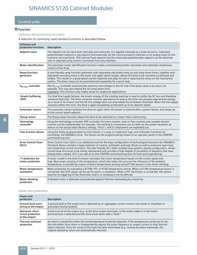
6 6
6/10 Siemens D21.7 – 2013
SINAMICS S120 Cabinet Modules
Control units
Function
Software and protective functions
Aselectionofcommonlyusedstandardfunctionsisdescribedbelow:
Software and protective functions Description
Setpoint input Thesetpointcanbeinputbothinternallyandexternally.Itisappliedinternallyasafixedsetpoint,motorizedpotentiometersetpointorjogsetpointandexternallyviathecommunicationsinterfaceorananaloginputonthecustomerterminalblock.Theinternalfixedsetpointandthemotorizedpotentiometersetpointcanbeswitchedoveroradjustedusingcontrolcommandsfromanyinterface.
Motor identification Theautomaticmotoridentificationfunctionmakescommissioningfasterandeasierandoptimizesclosed-loopcontrolofthedrive.
Ramp-functiongenerator
Auser-friendlyramp-functiongeneratorwithseparatelyadjustablerampupandrampdowntimes,togetherwithadjustableroundingtimesinthelowerandupperspeedranges,allowsthedrivetobesmoothlyacceleratedandbraked.Thisresultsinagoodspeedcontrolresponseandplaysitsroleinreducingthestressonthemechanicalsystem.Thedownrampcanbeparameterizedseparatelyforaquickstop.
Vdc max controller TheVdcmaxcontrollerautomaticallypreventsovervoltagesintheDClinkifthedownrampistooshort,forexample.Thismayalsoextendthesetramp-downtime.Comment:Thisfunctiononlymakessenseforsingle-axisapplications.
Kinetic buffering (KIP)
Forbrieflinesupplyfailures,thekineticenergyoftherotatingmachineisusedtobuffertheDCbusandthereforepreventsfaulttrips.ThedriveconverterremainsoperationalaslongasthedrivecanprovideregenerativeenergyasaresultofitsmotionandtheDClinkvoltagedoesnotdropbelowtheshutdownthreshold.Whenthelinesupplyrecoverswithinthistime,thedriveisagainbumplesslyaccelerateduptoitssetpointspeed.
Automatic restart Theautomaticrestartswitchesthedriveonagainwhenthepowerisrestoredafterapowerfailure,andrampsuptothecurrentspeedsetpoint.
Flying restart Theflyingrestartfunctionallowsthedrivetobeswitchedtoamotorthatisstillturning.
Technology controller
Usingthetechnologycontroller(PIDcontroller)functionmodule,levelorflowcontrolsandcomplextensioncontrolscanbeimplemented,forexample.TheexistingDcomponentcanactbothonthesystemdeviationaswellasontheactualvalue(factorysetting).TheP,I,andDcomponentsareseparatelyset.
Free function blocks Usingthefreelyprogrammablefunctionblocks,itiseasytoimplementlogicandarithmeticfunctionsforcontrollingtheSINAMICSdrive.TheblockscanbeprogrammedbymeansofanoperatorpanelortheSTARTERcommissioningtool.
Drive Control Chart(DCC)
DriveControlChart(DCC)isanadditionaltoolfortheeasyconfigurationoftechnologicalfunctionsforSINAMICS.Theblocklibrarycontainsalargeselectionofcontrol,arithmeticandlogicblocksaswellasextensiveopen-loopandclosedloopcontrolfunctions.Theuser-friendlyDCCEditorenableseasygraphics-basedconfiguration,allowscontrolloopstructurestobeclearlyrepresentedandprovidesahighdegreeofreusabilityofdiagramsthathavealreadybeencreated.DCCisanadd-ontotheSTARTERcommissioningtool( Toolsandengineering).
I 2t detection formotor protection
Amotormodelinthedrivefirmwarecalculatesthemotortemperaturebasedonthecurrentspeedandload.Moreexactsensingofthetemperature,whichalsotakesintoaccounttheinfluenceoftheambienttemperature,ispossiblebymeansofdirecttemperaturesensingusingKTY84sensorsinthemotorwinding.
Motor temperatureevaluation
MotorprotectionbyevaluatingaKTY84,PTCorPt100temperaturesensor.WhenaKTY84temperaturesensorisconnected,thelimitvaluescanbesetforalarmorshutdown.WhenaPTCthermistorisconnected,thesystemreactiontotriggeringofthethermistor(alarmorshutdown)canbedefined.
Motor blockingprotection
Ablockedmotorisdetectedandprotectedagainstthermaloverloadingbyafaulttrip.
Power unit protection Description
Ground fault moni-toring at the output
Agroundfaultattheoutputendisdetectedbyanaggregatecurrentmonitorandresultsinshutdowningrounded-neutralsystems.
Electronic short-circuit protection at the output
Ashort-circuitattheoutput(e.g.atthedriveoutputterminals,inthemotorcableorinthemotorterminalbox)isdetectedandthedriveshutsdownwitha“fault.”
Thermal overloadprotection
Analarmisissuedfirstwhentheovertemperaturethresholdresponds.Ifthetemperaturecontinuestorise,theuniteithershutsdownorindependentlyadjuststhepulsefrequencyoroutputcurrentsothatthermalloadisreduced.Oncethecauseofthefaulthasbeeneliminated(e.g.coolinghasbeenimproved),theoriginaloperatingvaluesareautomaticallyresumed.
Power unit protection
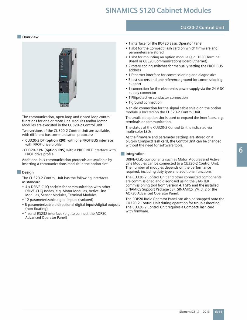
6 6
Siemens D21.7 – 2013 6/11
SINAMICS S120 Cabinet Modules
Overview
CU320-2 Control Unit
Thecommunication,open-loopandclosed-loopcontrolfunctionsforoneormoreLineModulesand/orMotorModulesareexecutedintheCU320-2ControlUnit.
TwoversionsoftheCU320-2ControlUnitareavailable,withdifferentbuscommunicationprotocols:
-CU320-2DP(option K90)withonePROFIBUSinterface withPROFIdriveprofile
-CU320-2PN(option K95)withaPROFINETinterfacewith PROFIdriveprofile
Additionalbuscommunicationprotocolsareavailablebyinsertingacommunicationsmoduleintheoptionslot.
Design
TheCU320-2ControlUnithasthefollowinginterfacesasstandard:•4xDRIVE-CLiQsocketsforcommunicationwithother DRIVE-CLiQnodes,e.g.MotorModules,ActiveLine Modules,SensorModules,TerminalModules•12parameterizabledigitalinputs(isolated)•8parameterizablebidirectionaldigitalinputs/digitaloutputs (non-floating)•1serialRS232interface(e.g.toconnecttheAOP30 AdvancedOperatorPanel)
•1interfacefortheBOP20BasicOperatorPanel•1slotfortheCompactFlashcardonwhichfirmwareand parametersarestored•1slotformountinganoptionmodule(e.g.TB30Terminal BoardorCBE20CommunicationsBoardEthernet)•2rotarycodingswitchesformanuallysettingthePROFIBUS address•1Ethernetinterfaceforcommissioninganddiagnostics•3testsocketsandonereferencegroundforcommissioning support•1connectionfortheelectronicspowersupplyviathe24VDC supplyconnector•1PE/protectiveconductorconnection•1groundconnection
AshieldconnectionforthesignalcableshieldontheoptionmoduleislocatedontheCU320-2ControlUnit.
Theavailableoptionslotisusedtoexpandtheinterfaces,e.g.terminalsorcommunication.
ThestatusoftheCU320-2ControlUnitisindicatedviamulti-colorLEDs.
Asthefirmwareandparametersettingsarestoredonaplug-inCompactFlashcard,theControlUnitcanbechangedwithouttheneedforsoftwaretools.
Integration
DRIVE-CLiQcomponentssuchasMotorModulesandActiveLineModulescanbeconnectedtoaCU320-2ControlUnit.Thenumberofmodulesdependsontheperformancerequired,includingdutytypeandadditionalfunctions.
TheCU320-2ControlUnitandotherconnectedcomponentsarecommissionedanddiagnosedusingtheSTARTERcommissioningtoolfromVersion4.1SP5andtheinstalledSINAMICSSupportPackageSSP_SINAMICS_V4_3_2ortheAOP30AdvancedOperatorPanel.
TheBOP20BasicOperatorPanelcanalsobesnappedontotheCU320-2ControlUnitduringoperationfortroubleshooting.TheCU320-2ControlUnitrequiresaCompactFlashcardwithfirmware.
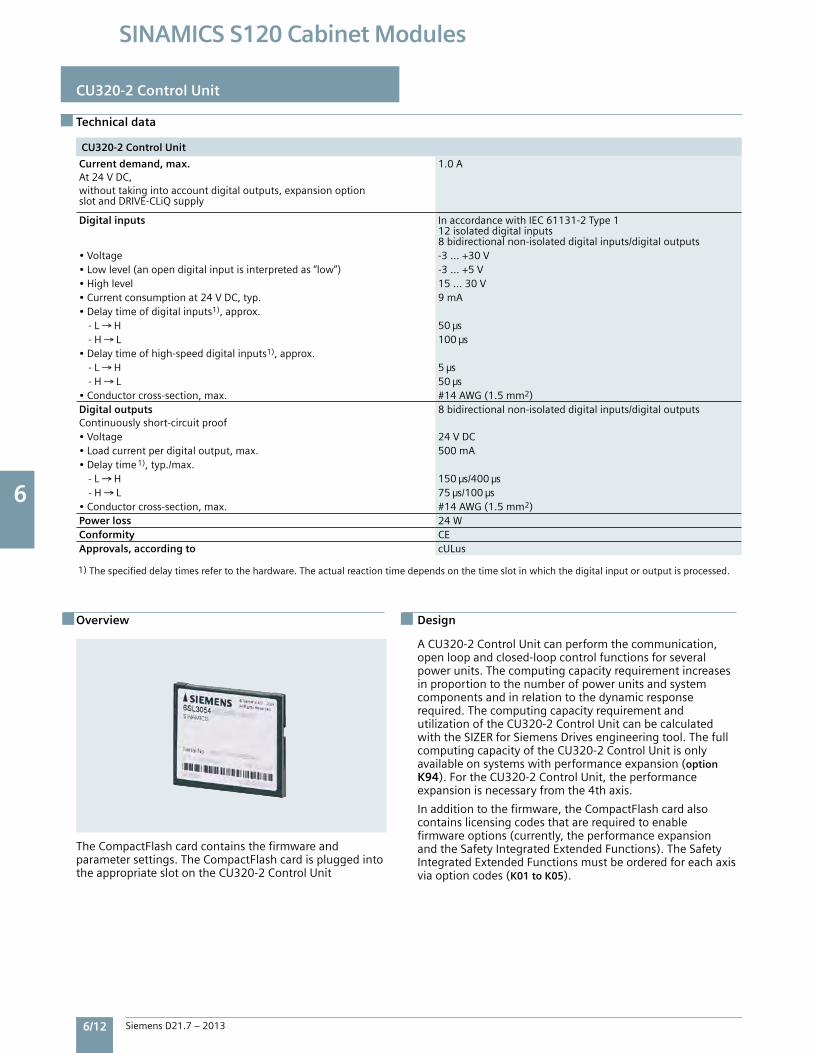
6 6
6/12 Siemens D21.7 – 2013
SINAMICS S120 Cabinet Modules
CU320-2 Control Unit
Technical data
CU320-2 Control Unit
Current demand, max.At24VDC,withouttakingintoaccountdigitaloutputs,expansionoptionslotandDRIVE-CLiQsupply
1.0A
Digital inputs InaccordancewithIEC61131-2Type112isolateddigitalinputs8bidirectionalnon-isolateddigitalinputs/digitaloutputs
•Voltage -3…+30V•Lowlevel(anopendigitalinputisinterpretedas“low”) -3…+5V•Highlevel 15…30V•Currentconsumptionat24VDC,typ. 9mA•Delaytimeofdigitalinputs1),approx. -L H 50 s -H L 100 s•Delaytimeofhigh-speeddigitalinputs1),approx. -L H 5 s -H L 50 s•Conductorcross-section,max. #14AWG(1.5mm2)Digital outputsContinuouslyshort-circuitproof
8bidirectionalnon-isolateddigitalinputs/digitaloutputs
•Voltage 24VDC•Loadcurrentperdigitaloutput,max. 500mA•Delaytime1),typ./max. -L H 150 s/400 s -H L 75 s/100 s•Conductorcross-section,max. #14AWG(1.5mm2)Power loss 24WConformity CEApprovals, according to cULus
Overview
TheCompactFlashcardcontainsthefirmwareandparametersettings.TheCompactFlashcardispluggedintotheappropriateslotontheCU320-2ControlUnit
Design
ACU320-2ControlUnitcanperformthecommunication,openloopandclosed-loopcontrolfunctionsforseveralpowerunits.Thecomputingcapacityrequirementincreasesinproportiontothenumberofpowerunitsandsystemcomponentsandinrelationtothedynamicresponserequired.ThecomputingcapacityrequirementandutilizationoftheCU320-2ControlUnitcanbecalculatedwiththeSIZERforSiemensDrivesengineeringtool.ThefullcomputingcapacityoftheCU320-2ControlUnitisonlyavailableonsystemswithperformanceexpansion(optionK94).FortheCU320-2ControlUnit,theperformanceexpansionisnecessaryfromthe4thaxis.
Inadditiontothefirmware,theCompactFlashcardalsocontainslicensingcodesthatarerequiredtoenablefirmwareoptions(currently,theperformanceexpansionandtheSafetyIntegratedExtendedFunctions).TheSafetyIntegratedExtendedFunctionsmustbeorderedforeachaxisviaoptioncodes(K01 to K05).
1)Thespecifieddelaytimesrefertothehardware.Theactualreactiontimedependsonthetimeslotinwhichthedigitalinputoroutputisprocessed.
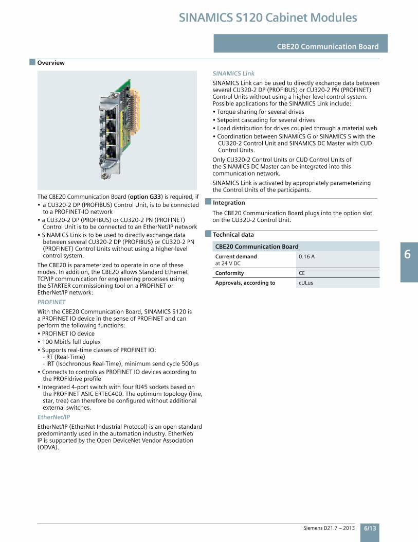
6 6
Siemens D21.7 – 2013 6/13
SINAMICS S120 Cabinet Modules
CBE20 Communication Board
Overview
TheCBE20CommunicationBoard(option G33)isrequired,if• aCU320-2DP(PROFIBUS)ControlUnit,istobeconnected toaPROFINET-IOnetwork•aCU320-2DP(PROFIBUS)orCU320-2PN(PROFINET) ControlUnitistobeconnectedtoanEtherNet/IPnetwork•SINAMICSLinkistobeusedtodirectlyexchangedata betweenseveralCU320-2DP(PROFIBUS)orCU320-2PN (PROFINET)ControlUnitswithoutusingahigher-level controlsystem.
TheCBE20isparameterizedtooperateinoneofthesemodes.Inaddition,theCBE20allowsStandardEthernetTCP/IPcommunicationforengineeringprocessesusingtheSTARTERcommissioningtoolonaPROFINETorEtherNet/IPnetwork:
PROFINET
WiththeCBE20CommunicationBoard,SINAMICSS120isaPROFINETIOdeviceinthesenseofPROFINETandcanperformthefollowingfunctions:•PROFINETIOdevice•100Mbit/sfullduplex•Supportsreal-timeclassesofPROFINETIO: -RT(Real-Time) -IRT(IsochronousReal-Time),minimumsendcycle500 s•ConnectstocontrolsasPROFINETIOdevicesaccordingto thePROFIdriveprofile•Integrated4-portswitchwithfourRJ45socketsbasedon thePROFINETASICERTEC400.Theoptimumtopology(line, star,tree)canthereforebeconfiguredwithoutadditional externalswitches.
EtherNet/IP
EtherNet/IP(EtherNetIndustrialProtocol)isanopenstandardpredominantlyusedintheautomationindustry.EtherNet/IPissupportedbytheOpenDeviceNetVendorAssociation(ODVA).
SINAMICS Link
SINAMICSLinkcanbeusedtodirectlyexchangedatabetweenseveralCU320-2DP(PROFIBUS)orCU320-2PN(PROFINET)ControlUnitswithoutusingahigher-levelcontrolsystem.PossibleapplicationsfortheSINAMICSLinkinclude:•Torquesharingforseveraldrives•Setpointcascadingforseveraldrives•Loaddistributionfordrivescoupledthroughamaterialweb•CoordinationbetweenSINAMICSGorSINAMICSSwiththe CU320-2ControlUnitandSINAMICSDCMasterwithCUD ControlUnits.
OnlyCU320-2ControlUnitsorCUDControlUnitsoftheSINAMICSDCMastercanbeintegratedintothiscommunicationnetwork.
SINAMICSLinkisactivatedbyappropriatelyparameterizingtheControlUnitsoftheparticipants.
TheCBE20CommunicationBoardplugsintotheoptionslotontheCU320-2ControlUnit.
CBE20 Communication Board
Current demandat24VDC
0.16A
Conformity CE
Approvals, according to cULus
Integration
Technical data
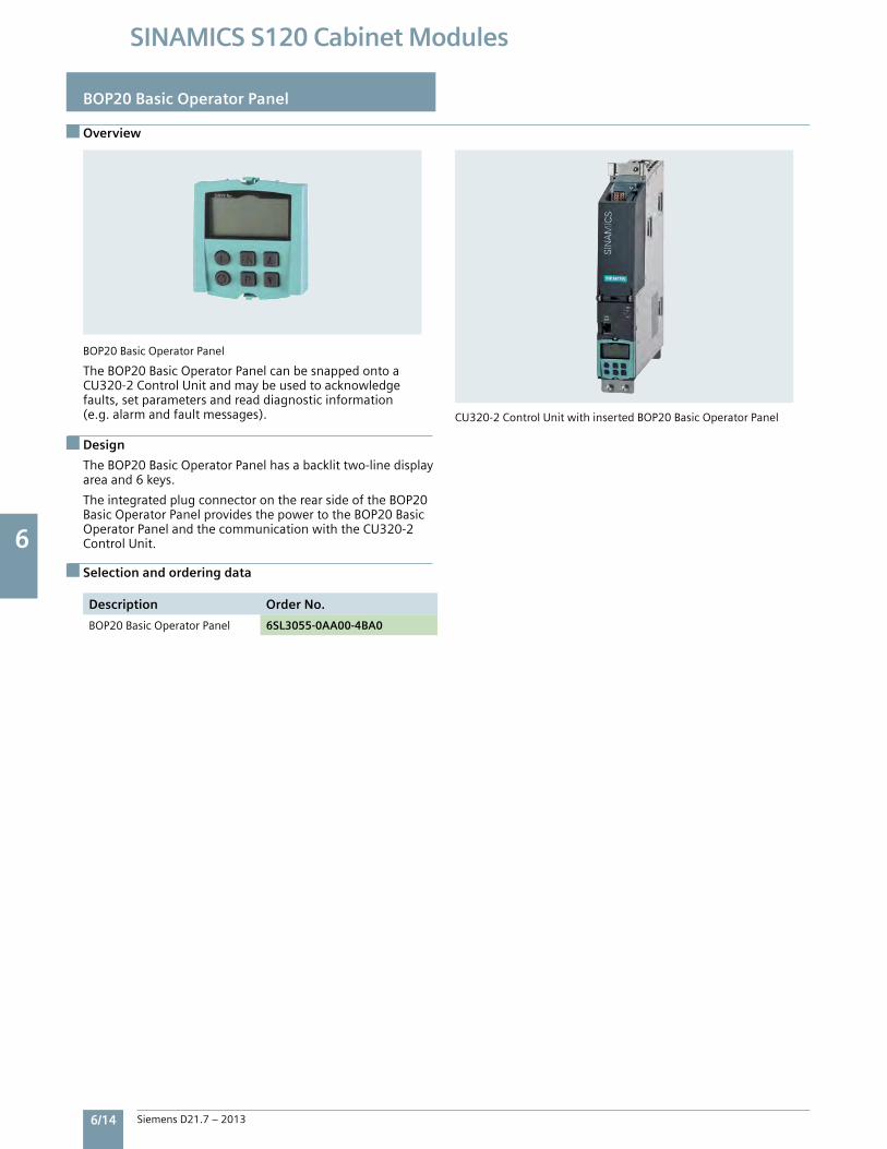
6 6
6/14 Siemens D21.7 – 2013
SINAMICS S120 Cabinet Modules
Overview
BOP20 Basic Operator Panel
BOP20BasicOperatorPanel
TheBOP20BasicOperatorPanelcanbesnappedontoaCU320-2ControlUnitandmaybeusedtoacknowledgefaults,setparametersandreaddiagnosticinformation(e.g.alarmandfaultmessages).
Design
TheBOP20BasicOperatorPanelhasabacklittwo-linedisplayareaand6keys.
TheintegratedplugconnectorontherearsideoftheBOP20BasicOperatorPanelprovidesthepowertotheBOP20BasicOperatorPanelandthecommunicationwiththeCU320-2ControlUnit.
Selection and ordering data
Description Order No.
BOP20BasicOperatorPanel 6SL3055-0AA00-4BA0
CU320-2ControlUnitwithinsertedBOP20BasicOperatorPanel
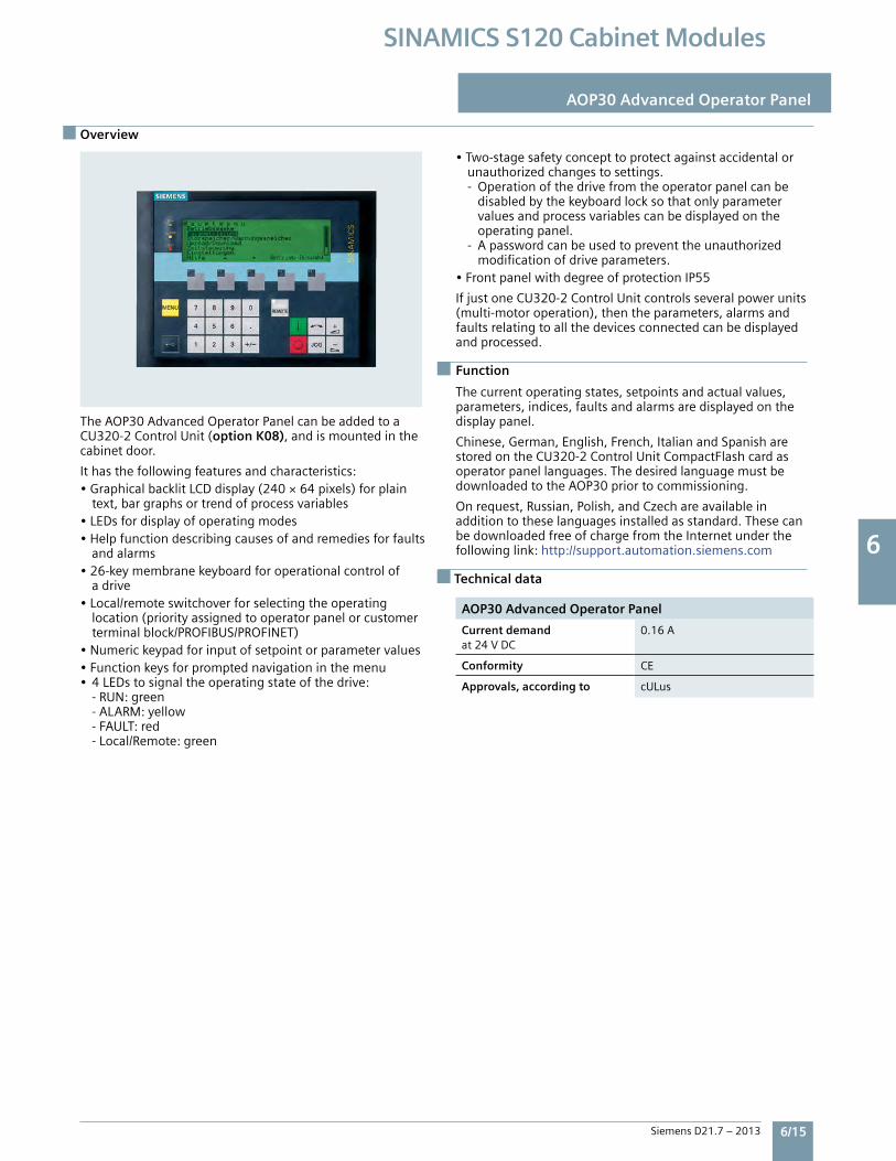
6 6
Siemens D21.7 – 2013 6/15
SINAMICS S120 Cabinet Modules
Overview
AOP30 Advanced Operator Panel
Function
Technical data
TheAOP30AdvancedOperatorPanelcanbeaddedtoaCU320-2ControlUnit(option K08),andismountedinthecabinetdoor.
Ithasthefollowingfeaturesandcharacteristics:•GraphicalbacklitLCDdisplay(240×64pixels)forplain text,bargraphsortrendofprocessvariables•LEDsfordisplayofoperatingmodes•Helpfunctiondescribingcausesofandremediesforfaults andalarms•26-keymembranekeyboardforoperationalcontrolof adrive•Local/remoteswitchoverforselectingtheoperating location(priorityassignedtooperatorpanelorcustomer terminalblock/PROFIBUS/PROFINET)•Numerickeypadforinputofsetpointorparametervalues•Functionkeysforpromptednavigationinthemenu• 4LEDstosignaltheoperatingstateofthedrive: -RUN:green -ALARM:yellow -FAULT:red -Local/Remote:green
•Two-stagesafetyconcepttoprotectagainstaccidentalor unauthorizedchangestosettings. -Operationofthedrivefromtheoperatorpanelcanbe disabledbythekeyboardlocksothatonlyparameter valuesandprocessvariablescanbedisplayedonthe operatingpanel. -Apasswordcanbeusedtopreventtheunauthorized modificationofdriveparameters.•FrontpanelwithdegreeofprotectionIP55
IfjustoneCU320-2ControlUnitcontrolsseveralpowerunits(multi-motoroperation),thentheparameters,alarmsandfaultsrelatingtoallthedevicesconnectedcanbedisplayedandprocessed.
Thecurrentoperatingstates,setpointsandactualvalues,parameters,indices,faultsandalarmsaredisplayedonthedisplaypanel.
Chinese,German,English,French,ItalianandSpanisharestoredontheCU320-2ControlUnitCompactFlashcardasoperatorpanellanguages.ThedesiredlanguagemustbedownloadedtotheAOP30priortocommissioning.
Onrequest,Russian,Polish,andCzechareavailableinadditiontotheselanguagesinstalledasstandard.ThesecanbedownloadedfreeofchargefromtheInternetunderthefollowinglink:http://support.automation.siemens.com
AOP30 Advanced Operator Panel
Current demandat24VDC
0.16A
Conformity CE
Approvals, according to cULus
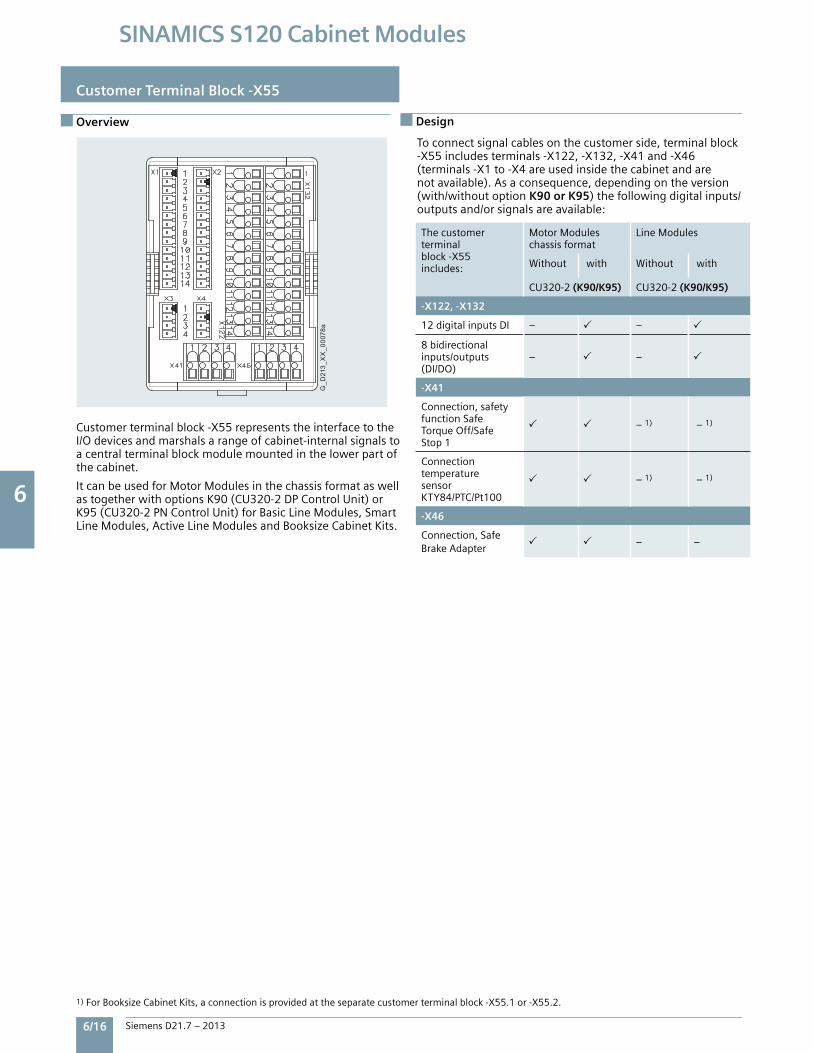
6 6
6/16 Siemens D21.7 – 2013
SINAMICS S120 Cabinet Modules
G_D
213_
XX
_000
78a
Overview
Customer Terminal Block -X55
Thecustomerterminalblock-X55includes:
MotorModuleschassisformat
LineModules
Without with Without with
CU320-2 (K90/K95) CU320-2(K90/K95)
-X122, -X132
12digitalinputsDI – –
8bidirectionalinputs/outputs(DI/DO)
– –
-X41
Connection,safetyfunctionSafeTorqueOff/SafeStop1
–1) –1)
ConnectiontemperaturesensorKTY84/PTC/Pt100
–1) –1)
-X46
Connection,SafeBrakeAdapter
– –
1)ForBooksizeCabinetKits,aconnectionisprovidedattheseparatecustomerterminalblock-X55.1or-X55.2.
Design
Customerterminalblock-X55representstheinterfacetotheI/Odevicesandmarshalsarangeofcabinet-internalsignalstoacentralterminalblockmodulemountedinthelowerpartofthecabinet.
ItcanbeusedforMotorModulesinthechassisformataswellastogetherwithoptionsK90(CU320-2DPControlUnit)orK95(CU320-2PNControlUnit)forBasicLineModules,SmartLineModules,ActiveLineModulesandBooksizeCabinetKits.
Toconnectsignalcablesonthecustomerside,terminalblock-X55includesterminals-X122,-X132,-X41and-X46(terminals-X1to-X4areusedinsidethecabinetandarenotavailable).Asaconsequence,dependingontheversion(with/withoutoptionK90 or K95)thefollowingdigitalinputs/outputsand/orsignalsareavailable:
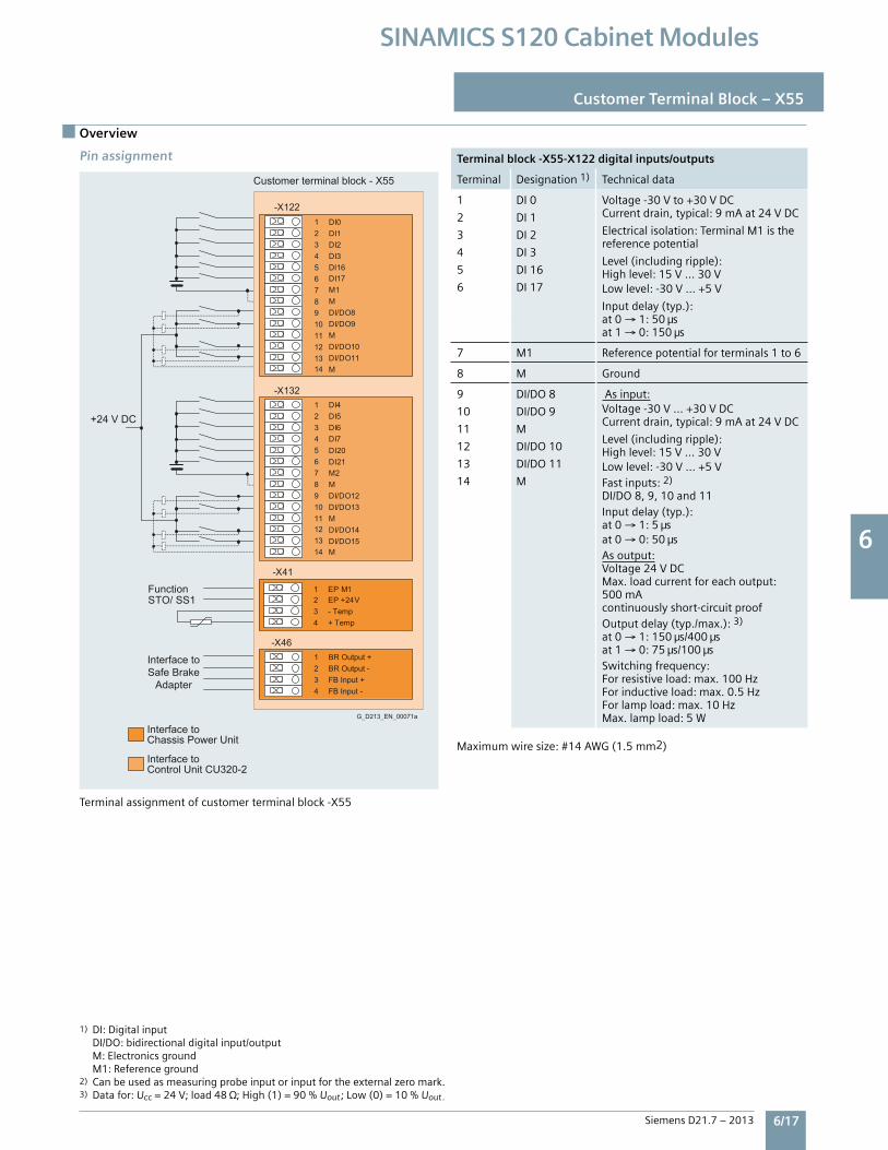
6 6
Siemens D21.7 – 2013 6/17
SINAMICS S120 Cabinet Modules
Overview
Pin assignmentTerminalassignmentofcustomerterminalblock-X55
Terminal block -X55-X122 digital inputs/outputs
Terminal Designation1) Technicaldata
1
2
3
4
5
6
DI0
DI1
DI2
DI3
DI16
DI17
Voltage-30Vto+30VDCCurrentdrain,typical:9mAat24VDC
Electricalisolation:TerminalM1isthereferencepotential
Level(includingripple):Highlevel:15V...30VLowlevel:-30V...+5V
Inputdelay(typ.):at0→1:50 sat1→ 0:150 s
7 M1 Referencepotentialforterminals1to6
8 M Ground
9
10
11
12
13
14
DI/DO8
DI/DO9
M
DI/DO10
DI/DO11
M
Asinput:Voltage-30V...+30VDCCurrentdrain,typical:9mAat24VDC
Level(includingripple):Highlevel:15V...30VLowlevel:-30V...+5VFastinputs:2)
DI/DO8,9,10and11Inputdelay(typ.):at0→ 1:5 sat0→0:50 sAsoutput:Voltage24VDCMax.loadcurrentforeachoutput:500mAcontinuouslyshort-circuitproofOutputdelay(typ./max.):3)
at0→1:150 s/400 sat1→ 0:75 s/100 sSwitchingfrequency:Forresistiveload:max.100HzForinductiveload:max.0.5HzForlampload:max.10HzMax.lampload:5W
Maximumwiresize:#14AWG(1.5mm2)
Customer Terminal Block – X55
1)DI:Digitalinput DI/DO:bidirectionaldigitalinput/output M:Electronicsground M1:Referenceground2) Canbeusedasmeasuringprobeinputorinputfortheexternalzeromark.3) Datafor:Ucc=24V;load48 ;High(1)=90%Uout;Low(0)=10%Uout.
Interface toChassis Power Unit
Customer terminal block - X55
G_D213_EN_00071a
Interface toControl Unit CU320-2
Function
Interface toSafe Brake
Adapter
+24 V DC
-X132
-X122
-X41
1 DI02 DI13 DI24 DI35 DI16
DI17M1
6
M7
DI/DO88
DI/DO99
M10
DI/DO1011
DI/DO1112
M1314
1 DI42 DI53 DI64 DI
DI20DI21
75
M26
M7
DI/DO128
DI/DO139
M10
DI/DO1411
DI/DO1512
M1314
-X461 BR Output +2 BR Output -3 FB Input +4 FB Input -
STO/ SS11 EP M12 EP +24V3 - Temp4 + Temp
Terminalassignmentofcustomerterminalblock-X55
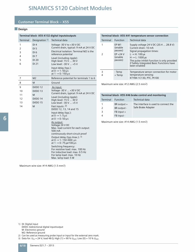
6 6
6/18 Siemens D21.7 – 2013
SINAMICS S120 Cabinet Modules
Design
Customer Terminal Block – X55
Terminal block -X55-X132 digital inputs/outputs
Terminal Designation1) Technicaldata
1
2
3
4
5
6
DI4
DI5
DI6
DI7
DI20
DI21
Voltage-30Vto+30VDCCurrentdrain,typical:9mAat24VDC
Electricalisolation:TerminalM2isthereferencepotential
Level(includingripple):Highlevel:15V...30VLowlevel:-30V...+5V
Inputdelay(typ.):at0→ 1:50 sat1→ 0:150 s
7 M2 Referencepotentialforterminals1to6
8 M Ground
9
10
11
12
13
14
DI/DO12
DI/DO13
M
DI/DO14
DI/DO15
M
Asinput:Voltage-30V...+30VDCCurrentdrain,typical:9mAat24VDC
Level(includingripple):Highlevel:15V...30VLowlevel:-30V...+5VFastinputs:2)
DI/DO12,13,14and15Inputdelay(typ.):at0→ 1:5 sat0→ 0:50 sAsoutput:Voltage24VDCMax.loadcurrentforeachoutput:500mAcontinuouslyshort-circuitproofOutputdelay(typ./max.):3)
at0→ 1:150/400 sat1→0:75 s/100 sSwitchingfrequency:Forresistiveload:max.100HzForinductiveload:max.0.5HzForlampload:max.10HzMax.lampload:5W
Maximumwiresize:#14AWG(1.5mm2)
Terminal block -X55-X41 temperature sensor connection
Terminal Function Technicaldata
1
2
EPM1(enablepauses)
EP+24V(enablepauses)
Supplyvoltage24VDC(20.4...28.8V)Currentdrain:10mASignalpropagationtimes:L→ H:100 sH→ L:1000 sThepulseinhibitfunctionisonlyprovidedifSafetyIntegratedBasicFunctionshavebeenenabled
34
-Temp+Temp
Temperaturesensorconnectionformotortemperaturesensing:KTY84-1C130,PTC,Pt100
Maximumwiresize:#12AWG(2.5mm2)
Terminal block -X55-X46 brake control and monitoring
Terminal Function Technicaldata
1
2
3
4
BRoutput+
BRoutput-
FBinput+
FBinput-
TheinterfaceisusedtoconnecttheSafeBrakeAdapter
Maximumwiresize:#14AWG(1.5mm2)
1)DI:Digitalinput DI/DO:bidirectionaldigitalinput/output M:Electronicsground M2:Referenceground2) Canbeusedasmeasuringprobeinputorinputfortheexternalzeromark.3) Datafor:Ucc=24V;load48 ;High(1)=90%Uout;Low(0)=10%Uout.
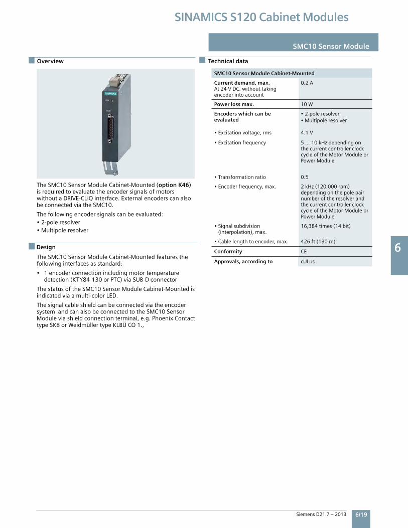
6 6
Siemens D21.7 – 2013 6/19
SINAMICS S120 Cabinet Modules
SMC10 Sensor Module
SMC10 Sensor Module Cabinet-Mounted
Current demand, max.At24VDC,withouttakingencoderintoaccount
0.2A
Power loss max. 10W
Encoders which can be evaluated
•2-poleresolver•Multipoleresolver
•Excitationvoltage,rms 4.1V
•Excitationfrequency 5...10kHzdependingonthecurrentcontrollerclockcycleoftheMotorModuleorPowerModule
•Transformationratio 0.5
•Encoderfrequency,max. 2kHz(120,000rpm)dependingonthepolepairnumberoftheresolverandthecurrentcontrollerclockcycleoftheMotorModuleorPowerModule
•Signalsubdivision(interpolation),max.
16,384times(14bit)
•Cablelengthtoencoder,max. 426ft(130m)
Conformity CE
Approvals, according to cULus
Design
TheSMC10SensorModuleCabinet-Mounted(option K46)isrequiredtoevaluatetheencodersignalsofmotorswithoutaDRIVE-CLiQinterface.ExternalencoderscanalsobeconnectedviatheSMC10.
Thefollowingencodersignalscanbeevaluated:•2-poleresolver•Multipoleresolver
TheSMC10SensorModuleCabinet-Mountedfeaturesthefollowinginterfacesasstandard:
• 1encoderconnectionincludingmotortemperature detection(KTY84-130orPTC)viaSUB-Dconnector
ThestatusoftheSMC10SensorModuleCabinet-Mountedisindicatedviaamulti-colorLED.
ThesignalcableshieldcanbeconnectedviatheencodersystemandcanalsobeconnectedtotheSMC10SensorModuleviashieldconnectionterminal,e.g.PhoenixContacttypeSK8orWeidmüllertypeKLBÜCO1.,
Technical dataOverview Technical data
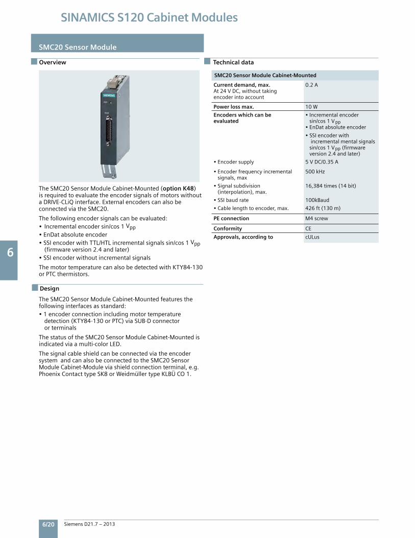
6 6
6/20 Siemens D21.7 – 2013
SINAMICS S120 Cabinet Modules
Technical data
SMC20 Sensor Module
SMC20 Sensor Module Cabinet-Mounted
Current demand, max.At24VDC,withouttakingencoderintoaccount
0.2A
Power loss max. 10W
Encoders which can be evaluated
•Incrementalencodersin/cos1V pp•EnDatabsoluteencoder
•SSIencoderwithincrementalmentalsignalssin/cos1Vpp(firmwareversion2.4andlater)
•Encodersupply 5VDC/0.35A
•Encoderfrequencyincrementalsignals,max
500kHz
•Signalsubdivision(interpolation),max.
16,384times(14bit)
•SSIbaudrate 100kBaud
•Cablelengthtoencoder,max. 426ft(130m)
PE connection M4screw
Conformity CE
Approvals, according to cULus
Design
Overview Technical data
TheSMC20SensorModuleCabinet-Mounted(option K48)isrequiredtoevaluatetheencodersignalsofmotorswithoutaDRIVE-CLiQinterface.ExternalencoderscanalsobeconnectedviatheSMC20.
Thefollowingencodersignalscanbeevaluated:•Incrementalencodersin/cos1Vpp•EnDatabsoluteencoder•SSIencoderwithTTL/HTLincrementalsignalssin/cos1Vpp (firmwareversion2.4andlater)•SSIencoderwithoutincrementalsignals
ThemotortemperaturecanalsobedetectedwithKTY84-130orPTCthermistors.
TheSMC20SensorModuleCabinet-Mountedfeaturesthefollowinginterfacesasstandard:•1encoderconnectionincludingmotortemperature detection(KTY84-130orPTC)viaSUB-Dconnector orterminals
ThestatusoftheSMC20SensorModuleCabinet-Mountedisindicatedviaamulti-colorLED.
ThesignalcableshieldcanbeconnectedviatheencodersystemandcanalsobeconnectedtotheSMC20SensorModuleCabinet-Moduleviashieldconnectionterminal,e.g.PhoenixContacttypeSK8orWeidmüllertypeKLBÜCO1.
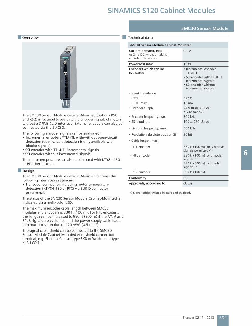
6 6
Siemens D21.7 – 2013 6/21
SINAMICS S120 Cabinet Modules
Overview
SMC30 Sensor Module
Design
SMC30 Sensor Module Cabinet-Mounted
Current demand, max.At 24 V DC, without taking encoder into account
0.2 A
Power loss max. 10 W
Encoders which can be evaluated
• Incremental encoder TTL/HTL• SSI encoder with TTL/HTL incremental signals• SSI encoder without incremental signals
• Input impedence
- TTL 570
- HTL, max. 16 mA
• Encoder supply 24 V DC/0.35 A or5 V DC/0.35 A
• Encoder frequency max. 300 kHz
• SSI baud rate 100 ... 250 kBaud
• Limiting frequency, max. 300 kHz
• Resolution absolute position SSI 30 bit
• Cable length, max.
- TTL encoder 330 ft (100 m) (only bipolar signals permitted) 1)
- HTL encoder 330 ft (100 m) for unipolar signals 990 ft (300 m) for bipolar signals 1)
- SSI encoder 330 ft (100 m)
Conformity CE
Approvals, according to cULus
Technical data
The SMC30 Sensor Module Cabinet-Mounted (options K50and K52) is required to evaluate the encoder signals of motors without a DRIVE-CLiQ interface. External encoders can also be connected via the SMC30.
The following encoder signals can be evaluated:• Incremental encoders TTL/HTL with/without open-circuit detection (open-circuit detection is only available with bipolar signals)• SSI encoder with TTL/HTL incremental signals• SSI encoder without incremental signals
The motor temperature can also be detected with KTY84-130 or PTC thermistors.
The SMC30 Sensor Module Cabinet-Mounted features the following interfaces as standard:• 1 encoder connection including motor temperature detection (KTY84-130 or PTC) via SUB-D connector or terminals
The status of the SMC30 Sensor Module Cabinet-Mounted isindicated via a multi-color LED.
The maximum encoder cable length between SMC30 modules and encoders is 330 ft (100 m). For HTL encoders, this length can be increased to 990 ft (300 m) if the A*, A and B*, B signals are evaluated and the power supply cable has a minimum cross-section of #20 AWG (0.5 mm2).
The signal cable shield can be connected to the SMC30 Sensor Module Cabinet-Mounted via a shield connection terminal, e.g. Phoenix Contact type SK8 or Weidmüller type KLBÜ CO 1.
1) Signal cables twisted in pairs and shielded.
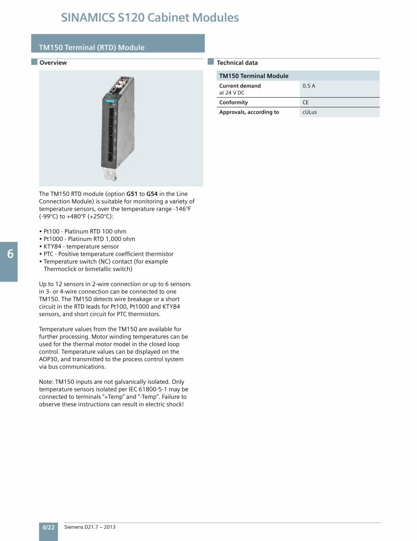
6 6
6/22 Siemens D21.7 – 2013
SINAMICS S120 Cabinet Modules
TM150 Terminal (RTD) Module
Overview Technical data
TM150 Terminal Module
Current demandat24VDC
0.5A
Conformity CE
Approvals, according to cULus
TheTM150RTDmodule(optionG51toG54intheLineConnectionModule)issuitableformonitoringavarietyoftemperaturesensors,overthetemperaturerange-146°F(-99°C)to+480°F(+250°C):
•Pt100-PlatinumRTD100ohm•Pt1000-PlatinumRTD1,000ohm•KTY84-temperaturesensor•PTC-Positivetemperaturecoefficientthermistor•Temperatureswitch(NC)contact(forexample Thermoclickorbimetallicswitch)
Upto12sensorsin2-wireconnectionorupto6sensorsin3-or4-wireconnectioncanbeconnectedtooneTM150.TheTM150detectswirebreakageorashortcircuitintheRTDleadsforPt100,Pt1000andKTY84sensors,andshortcircuitforPTCthermistors.
TemperaturevaluesfromtheTM150areavailableforfurtherprocessing.Motorwindingtemperaturescanbeusedforthethermalmotormodelintheclosedloopcontrol.TemperaturevaluescanbedisplayedontheAOP30,andtransmittedtotheprocesscontrolsystemviabuscommunications.
Note:TM150inputsarenotgalvanicallyisolated.OnlytemperaturesensorsisolatedperIEC61800-5-1maybeconnectedtoterminals“+Temp”and“-Temp”.Failuretoobservetheseinstructionscanresultinelectricshock!
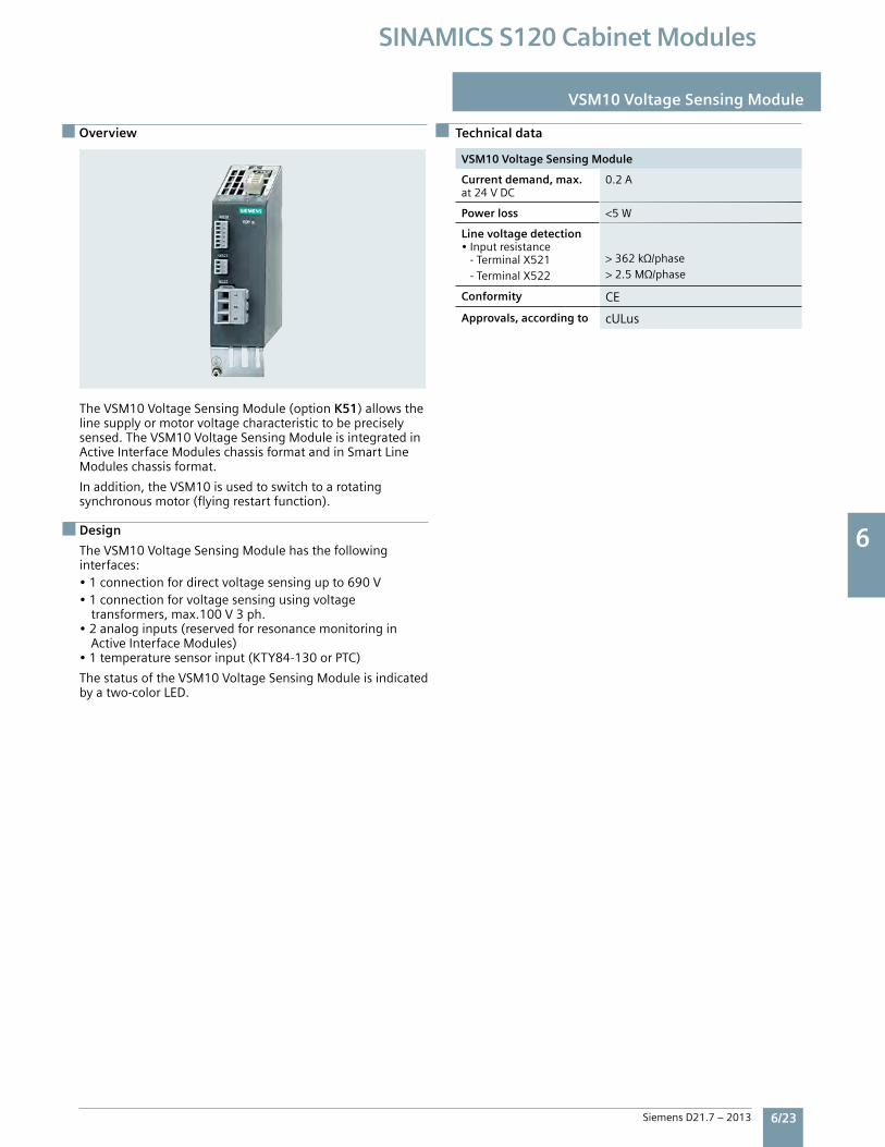
6 6
Siemens D21.7 – 2013 6/23
SINAMICS S120 Cabinet Modules
Overview
VSM10 Voltage Sensing Module
VSM10 Voltage Sensing Module
Current demand, max.at24VDC
0.2A
Power loss <5W
Line voltage detection•Inputresistance-TerminalX521-TerminalX522
>362kΩ/phase>2.5MΩ/phase
Conformity CE
Approvals, according to cULus
Technical data
TheVSM10VoltageSensingModule(optionK51)allowsthelinesupplyormotorvoltagecharacteristictobepreciselysensed.TheVSM10VoltageSensingModuleisintegratedinActiveInterfaceModuleschassisformatandinSmartLineModuleschassisformat.
Inaddition,theVSM10isusedtoswitchtoarotatingsynchronousmotor(flyingrestartfunction).
Design
TheVSM10VoltageSensingModulehasthefollowinginterfaces:•1connectionfordirectvoltagesensingupto690V•1connectionforvoltagesensingusingvoltage transformers,max.100V3ph.•2analoginputs(reservedforresonancemonitoringin ActiveInterfaceModules)•1temperaturesensorinput(KTY84-130orPTC)
ThestatusoftheVSM10VoltageSensingModuleisindicatedbyatwo-colorLED.
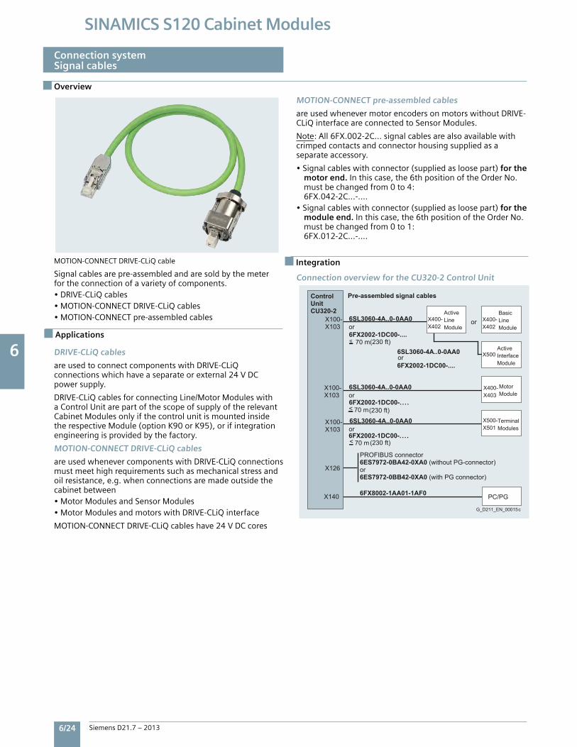
6 6
6/24 Siemens D21.7 – 2013
SINAMICS S120 Cabinet Modules
X140
X126
X100-X103
X400-X402
X100-X103
X100-X103
6SL3060-4A..0-0AA0
6FX2002-1DC00-....
6SL3060-4A..0-0AA0
6SL3060-4A..0-0AA0
6FX2002-1DC00-. . . .
6FX2002-1DC00-. . . .
6FX8002-1AA01-1AF0
X400-X402
X5006SL3060-4A..0-0AA0
6FX2002-1DC00-....
70 m<
70 m<
70 m<
Pre-assembled signal cablesControlUnitCU320-2 Active
LineModule
TerminalModules
MotorModule
or
or
PROFIBUS connector6ES7972-0BA42-0XA0 (without PG-connector)or6ES7972-0BB42-0XA0 (with PG connector)
or
BasicLineModule
or
ActiveInterfaceModule
or
X400-X403
X500-X501
PC/PG
(230 ft)
(230 ft)
(230 ft)
G_D211_EN_00015c
Overview
Connection systemSignal cables
Applications
IntegrationMOTION-CONNECTDRIVE-CLiQcable
Signalcablesarepre-assembledandaresoldbythemeterfortheconnectionofavarietyofcomponents.•DRIVE-CLiQcables•MOTION-CONNECTDRIVE-CLiQcables•MOTION-CONNECTpre-assembledcables
DRIVE-CLiQ cables
areusedtoconnectcomponentswithDRIVE-CLiQconnectionswhichhaveaseparateorexternal24VDCpowersupply.
DRIVE-CLiQcablesforconnectingLine/MotorModuleswithaControlUnitarepartofthescopeofsupplyoftherelevantCabinetModulesonlyifthecontrolunitismountedinsidetherespectiveModule(optionK90orK95),orifintegrationengineeringisprovidedbythefactory.
MOTION-CONNECT DRIVE-CLiQ cables
areusedwhenevercomponentswithDRIVE-CLiQconnectionsmustmeethighrequirementssuchasmechanicalstressandoilresistance,e.g.whenconnectionsaremadeoutsidethecabinetbetween•MotorModulesandSensorModules•MotorModulesandmotorswithDRIVE-CLiQinterface
MOTION-CONNECTDRIVE-CLiQcableshave24VDCcores
MOTION-CONNECT pre-assembled cables
areusedwhenevermotorencodersonmotorswithoutDRIVE-CLiQinterfaceareconnectedtoSensorModules.
Note:All6FX.002-2C...signalcablesarealsoavailablewithcrimpedcontactsandconnectorhousingsuppliedasaseparateaccessory.
•Signalcableswithconnector(suppliedasloosepart)for the motor end.Inthiscase,the6thpositionoftheOrderNo. mustbechangedfrom0to4: 6FX.042-2C...-....•Signalcableswithconnector(suppliedasloosepart)for the module end.Inthiscase,the6thpositionoftheOrderNo. mustbechangedfrom0to1: 6FX.012-2C...-....
Connection overview for the CU320-2 Control Unit
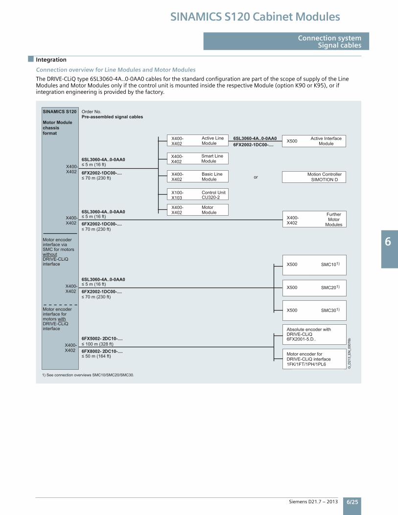
6 6
Siemens D21.7 – 2013 6/25
SINAMICS S120 Cabinet Modules
Integration
Connection systemSignal cables
Connection overview for Line Modules and Motor Modules
TheDRIVE-CLiQtype6SL3060-4A..0-0AA0cablesforthestandardconfigurationarepartofthescopeofsupplyoftheLineModulesandMotorModulesonlyifthecontrolunitismountedinsidetherespectiveModule(optionK90orK95),orifintegrationengineeringisprovidedbythefactory.
Order No.Pre-assembled signal cables
FurtherMotor
Modules
≤ 100 m (328 ft)
Motor encoder forDRIVE-CLiQ interface 1FK/1FT/1PH/1PL6
Motor encoderinterface formotors withDRIVE-CLiQinterface
≤ 50 m (164 ft)
≤ 70 m (230 ft)
≤ 70 m (230 ft)
≤ 5 m (16 ft)
≤ 5 m (16 ft)
≤ 70 m (230 ft)
≤ 5 m (16 ft)
Motor encoderinterface viaSMC for motorswithoutDRIVE-CLiQinterface
Absolute encoder withDRIVE-CLiQ6FX2001-5.D..
or
SINAMICS S120
Motor Modulechassisformat
G_D
213_
EN
_000
76b
Motion ControllerSIMOTION D
X100-X103
6SL3060-4A..0-0AA0
6FX2002-1DC00-....
6FX5002- 2DC10-....
6FX8002- 2DC10-....
6FX2002-1DC00-....
Control UnitCU320-2
X400-X402
X400-X402
X400-X402
X400-X402
X400-X402
X400-X402
X400-X402
X400-X402
6SL3060-4A..0-0AA06FX2002-1DC00-....
X500 Active InterfaceModule
1) See connection overviews SMC10/SMC20/SMC30.
X500 SMC101)
X500 SMC201)
X500 SMC301)
Smart LineModule
X400-X402
MotorModule
Active LineModule
Basic LineModule
6SL3060-4A..0-0AA0
6FX2002-1DC00-....
6SL3060-4A..0-0AA0
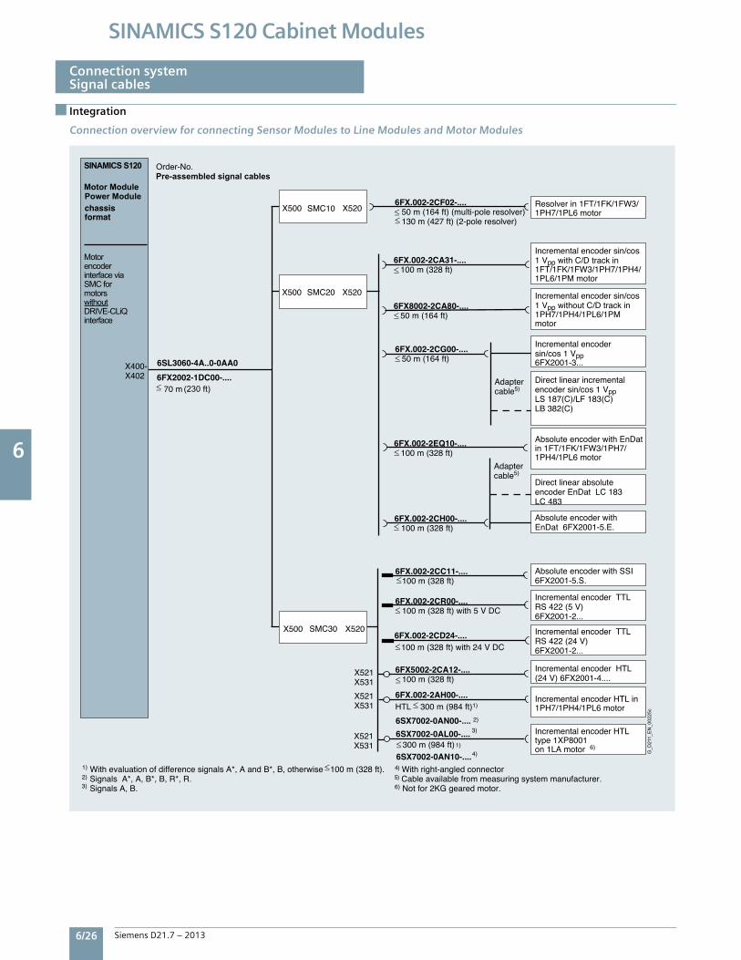
6 6
6/26 Siemens D21.7 – 2013
SINAMICS S120 Cabinet Modules
Integration
Connection systemSignal cables
Connection overview for connecting Sensor Modules to Line Modules and Motor Modules
1)
X500 X520
2)
3)
2)3)
4)
6FX2002-1DC00-....
X521X531
X521X531
SMC30
X521X531
X520X500 SMC20
X520X500 SMC10
X400-X402
Order-No.Pre-assembled signal cables
6FX.002-2EQ10-.... 100 m (328 ft)
6FX.002-2AH00-....HTL 300 m (984 ft)
6SX7002-0AL00-.... 300 m (984 ft)
6SL3060-4A..0-0AA0
With evaluation of difference signals A*, A and B*, B, otherwise 100 m (328 ft).Signals A*, A, B*, B, R*, R.Signals A, B.
Absolute encoder with EnDat in 1FT/1FK/1FW3/1PH7/1PH4/1PL6 motor
6FX.002-2CR00-.... 100 m (328 ft) with 5 V DC
Adapter cable5)
6SX7002-0AN00-....
Direct linear absolute encoder EnDat LC 183LC 483
Absolute encoder with EnDat 6FX2001-5.E.
Incremental encoder TTL RS 422 (5 V)6FX2001-2...
Incremental encoder TTL RS 422 (24 V)6FX2001-2...
Incremental encoder HTL in 1PH7/1PH4/1PL6 motor
Incremental encoder HTL type 1XP8001on 1LA motor
6FX.002-2CD24-.... 100 m (328 ft) with 24 V DC
6SX7002-0AN10-....
70 m
6FX.002-2CH00-.... 100 m (328 ft)
4) With right-angled connector5) Cable available from measuring system manufacturer.6) Not for 2KG geared motor.
1)
1)
Absolute encoder with SSI 6FX2001-5.S.
6FX.002-2CC11-.... 100 m (328 ft)
6FX5002-2CA12-.... 100 m (328 ft)
Incremental encoder HTL (24 V) 6FX2001-4....
6)
Adapter cable5)
Incremental encoder sin/cos 1 Vpp6FX2001-3...
Direct linear incremental encoder sin/cos 1 VppLS 187(C)/LF 183(C)LB 382(C)
6FX.002-2CA31-.... 100 m (328 ft)
Incremental encoder sin/cos 1 Vpp with C/D track in 1FT/1FK/1FW3/1PH7/1PH4/1PL6/1PM motor
6FX.002-2CG00-.... 50 m (164 ft)
6FX8002-2CA80-.... 50 m (164 ft)
Incremental encoder sin/cos 1 Vpp without C/D track in 1PH7/1PH4/1PL6/1PM motor
6FX.002-2CF02-.... 50 m (164 ft) (multi-pole resolver) 130 m (427 ft) (2-pole resolver)
Resolver in 1FT/1FK/1FW3/1PH7/1PL6 motor
SINAMICS S120
Motor ModulePower Modulechassis format
Motor encoder interface via SMC for motors without DRIVE-CLiQ interface
(230 ft)
G_D
211_
EN
_002
25c
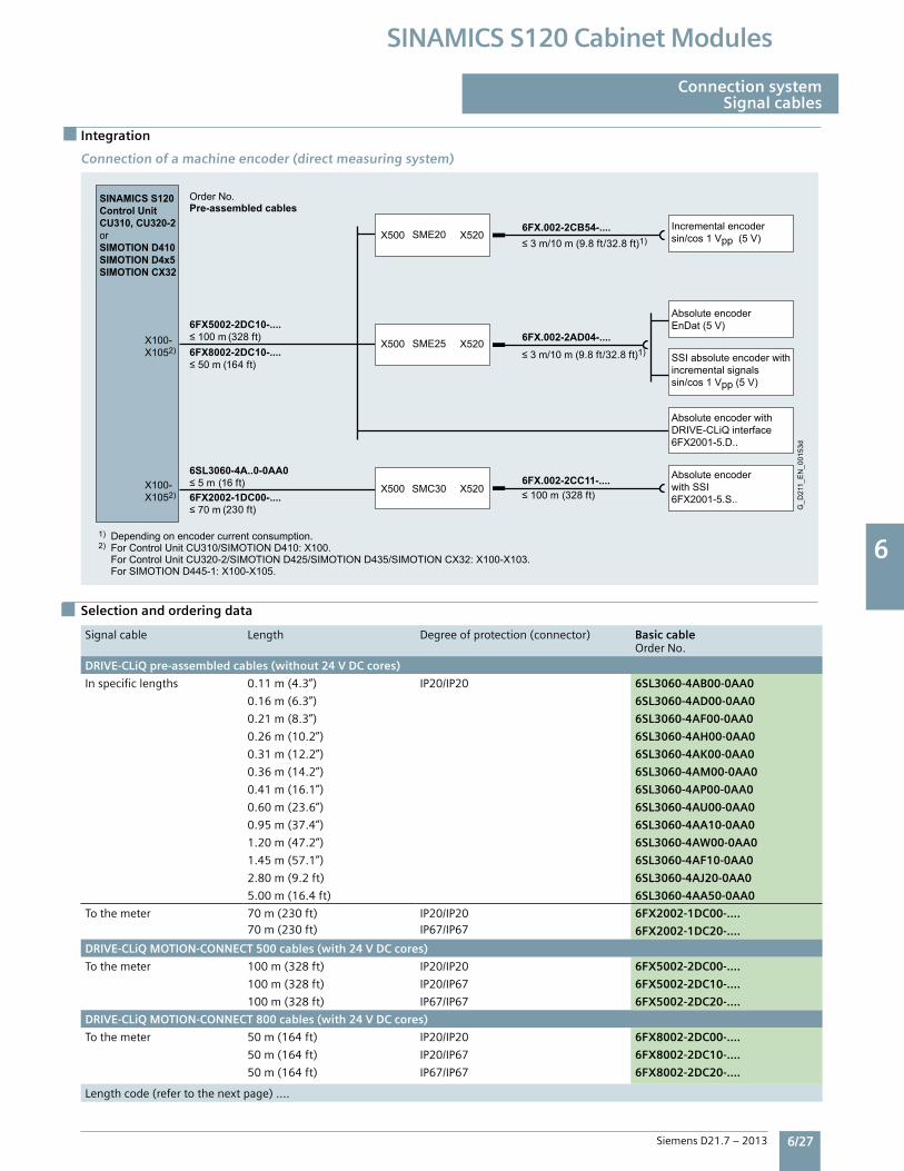
6 6
Siemens D21.7 – 2013 6/27
SINAMICS S120 Cabinet Modules
Integration
Selection and ordering data
Connection systemSignal cables
Connection of a machine encoder (direct measuring system)
Signalcable Length Degreeofprotection(connector) Basic cableOrderNo.
DRIVE-CLiQ pre-assembled cables (without 24 V DC cores)
Inspecificlengths 0.11m(4.3”) IP20/IP20 6SL3060-4AB00-0AA0
0.16m(6.3”) 6SL3060-4AD00-0AA0
0.21m(8.3”) 6SL3060-4AF00-0AA0
0.26m(10.2”) 6SL3060-4AH00-0AA0
0.31m(12.2”) 6SL3060-4AK00-0AA0
0.36m(14.2”) 6SL3060-4AM00-0AA0
0.41m(16.1”) 6SL3060-4AP00-0AA0
0.60m(23.6”) 6SL3060-4AU00-0AA0
0.95m(37.4”) 6SL3060-4AA10-0AA0
1.20m(47.2”) 6SL3060-4AW00-0AA0
1.45m(57.1”) 6SL3060-4AF10-0AA0
2.80m(9.2ft) 6SL3060-4AJ20-0AA0
5.00m(16.4ft) 6SL3060-4AA50-0AA0
Tothemeter 70m(230ft)70m(230ft)
IP20/IP20IP67/IP67
6FX2002-1DC00-….
6FX2002-1DC20-....
DRIVE-CLiQ MOTION-CONNECT 500 cables (with 24 V DC cores)
Tothemeter 100m(328ft) IP20/IP20 6FX5002-2DC00-....
100m(328ft) IP20/IP67 6FX5002-2DC10-….
100m(328ft) IP67/IP67 6FX5002-2DC20-….
DRIVE-CLiQ MOTION-CONNECT 800 cables (with 24 V DC cores)
Tothemeter 50m(164ft) IP20/IP20 6FX8002-2DC00-….
50m(164ft) IP20/IP67 6FX8002-2DC10-.…
50m(164ft) IP67/IP67 6FX8002-2DC20-….
Lengthcode(refertothenextpage)….
SINAMICS S120Control Unit CU310, CU320-2orSIMOTION D410SIMOTION D4x5SIMOTION CX32
1) Depending on encoder current consumption.2) For Control Unit CU310/SIMOTION D410: X100. For Control Unit CU320-2/SIMOTION D425/SIMOTION D435/SIMOTION CX32: X100-X103. For SIMOTION D445-1: X100-X105.
Incremental encodersin/cos 1 Vpp (5 V)
Absolute encoder with SSI6FX2001-5.S..
SSI absolute encoder with incremental signalssin/cos 1 Vpp (5 V)
G_D
211_
EN
_001
53d
Absolute encoderEnDat (5 V)
Absolute encoder with DRIVE-CLiQ interface6FX2001-5.D..
Order No.Pre-assembled cables
(328 ft)
(328 ft)
(164 ft)
(16 ft)
(230 ft)
≤ 3 m/10 m (9.8 ft/32.8 ft)1)
≤ 3 m/10 m (9.8 ft/32.8 ft)1)X100-X1052)
X100-X1052)
X520X500
6FX5002-2DC10-....≤ 100 m
6FX.002-2CB54-....
6FX.002-2CC11-....≤ 100 m
6FX.002-2AD04-....6FX8002-2DC10-....≤ 50 m
6SL3060-4A..0-0AA0≤ 5 m6FX2002-1DC00-....≤ 70 m
X520X500
X520X500
SME25
SMC30
SME20
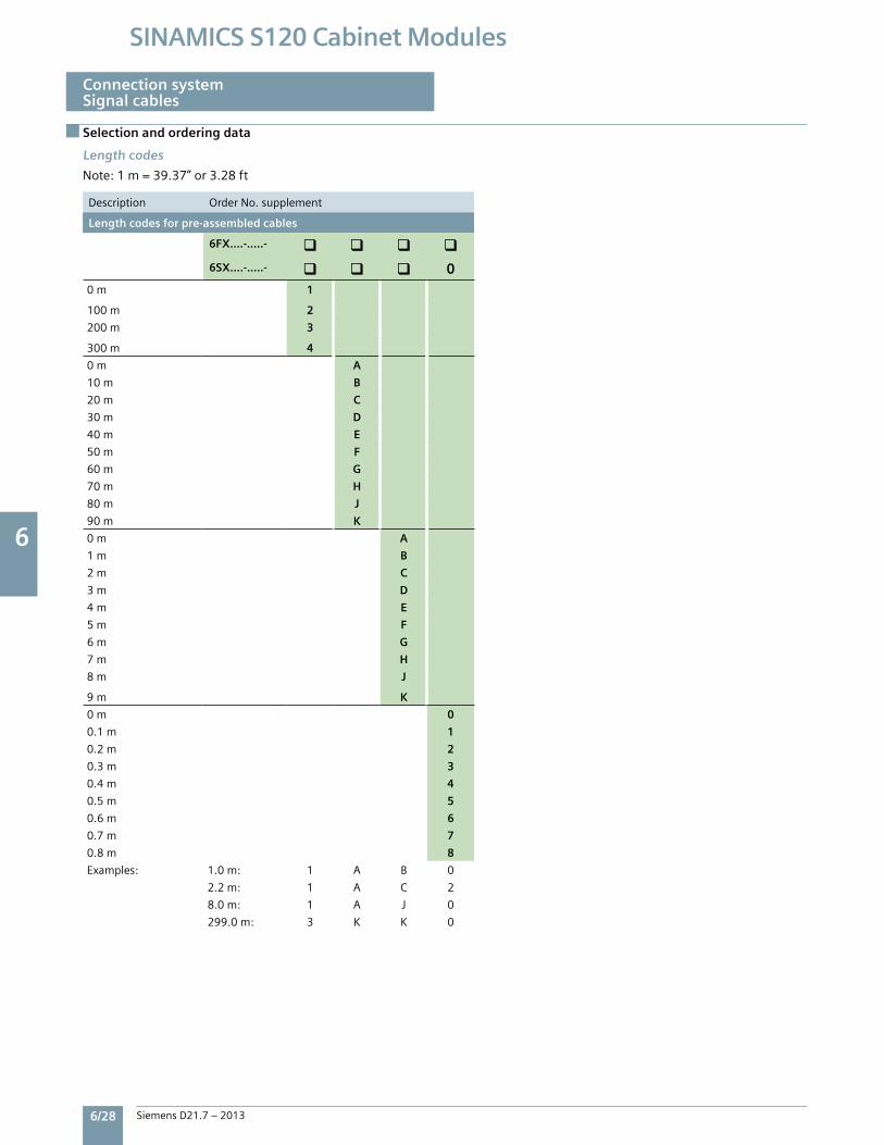
6 6
6/28 Siemens D21.7 – 2013
SINAMICS S120 Cabinet Modules
Selection and ordering data
Connection systemSignal cables
Length codes
Note:1m=39.37”or3.28ft
Description OrderNo.supplement
Length codes for pre-assembled cables
6FX....-.....-
6SX....-.....- 00m 1
100m 2
200m 3
300m 4
0m A
10m B
20m C
30m D
40m E
50m F
60m G
70m H
80m J
90m K
0m A
1m B
2m C
3m D
4m E
5m F
6m G
7m H
8m J
9m K
0m 0
0.1m 1
0.2m 2
0.3m 3
0.4m 4
0.5m 5
0.6m 6
0.7m 7
0.8m 8
Examples: 1.0m: 1 A B 0
2.2m: 1 A C 2
8.0m: 1 A J 0
299.0m: 3 K K 0
6 6
Siemens D21.7 – 2013 6/29
SINAMICS S120 Cabinet Modules
Function
Safety integrated
Safety Integrated functions
TheintegratedsafetyfunctionsofSINAMICSprovidehighlyeffectiveapplication-orientedprotectionforpersonnelandmachinery.TheSafetyIntegratedfunctionsareimplementedelectronicallyandthereforeoffershortresponsetimesincomparisontosolutionswithexternallyimplementedmonitoringfunctions.
Thetrendtowardgreatercomplexityandincreasingmodularityofmachinesisincreasinglyseeingashiftinsafetyfunctionsawayfromtheclassicalcentralsafetyfunctions(forexample,shutdownofthecompletemachineusingamainswitch)andintothemachinecontrolsystemandthedrives.Frequently,thisalsosignificantlyincreasestheproductivity.Thisisbecause,forinstance,equippingtimescanbereducedandduringtheseequippingtimes,dependingonthemachinetype,otherpartscanstillcontinuetoproduce.
Integratedsafetyfunctionsactmuchfasterthanthoseofaconventionaldesign.ThesafetyofamachineisincreasedfurtherwithSafetyIntegrated.Furthermore,thankstothefastermethodofoperation,safetymeasurescontrolledbyintegratedsafetysystemsareperceivedaslessofahindrancebythemachineoperator,thereforesignificantlyreducingthemotivationtoconsciouslybypasssafetyfunctions.
ThesafetyfunctionsinthedeviceandcommunicationviaPROFIsafehavealreadybeencertified.Thissimplifiesconfiguringthesafetyfunctionsandespeciallytheacceptanceoftheplantorsystembyanauthorizedtestingbodywhencomparedtosafetysolutionsmadeupofindi-vidualsafetycomponents.
LegalframeworkMachineandplantbuildersmustensurethattheirmachinesorplantsneitherpresentrisksduetoelectricshock,heatorradiationnorduetofunctionalfaults.InEurope,forexample,compliancewiththemachinerydirectiveislegallystipulatedbytheEUindustrialsafetydirective.
Inordertoensurecompliancewiththisdirective,itisrecommendedthatthecorrespondingharmonizedEuropeanstandardsareapplied.ThisinitiatestheassumptionofconformityandgivesmanufacturersandoperatorsthelegalsecuritywhencomplyingwithbothnationalregulationsandEUdirectives.ThemachinemanufacturerusestheCEmarkingtodocumentthecompliancewithallrelevantdirectivesandregulationsinthefreemovementofgoods.
Safety-relatedstandards
Functionalsafetyisspecifiedinvariousstandards.ISO12100andISO14121-1,forexample,areconcernedwiththedesignandriskassessmentofmachines.IEC62061(onlyapplicableforelectricalandelectroniccontrolsystems)andISO13849-1(previouslyEN954-1)definethefunctionalandsafety-relatedrequirementsofcontrolsystemswithrelevancetosafety.
Theabove-mentionedstandardsdefinedifferentsafetyrequirementsthatthemachinehastosatisfyinaccordancewiththerisk,frequencyofadangeroussituation,probabilityofoccurrenceandtheopportunitiesforrecognizingimpendingdanger.•ISO13849-1:ControlCategory1...4•ISO13849-1:PerformanceLevelPLa…e•IEC62061:SafetyIntegrityLevelSIL1…3
SafetyfunctionsintegratedinthedrivewithSINAMICS
ThesafetyfunctionsintegratedinSINAMICSsatisfytherequirementsof•ControlCategory3accordingtoISO13849-1•SafetyIntegrityLevel(SIL)2accordingtoIEC61508•PerformanceLevel(PL)daccordingtoISO13849-1
Inaddition,theSafetyIntegratedfunctionsofSINAMICSaregenerallycertifiedbyindependentinstitutes.Anup-to-datelistofcertifiedcomponentsisavailableonrequestfromyourlocalSiemensoffice.
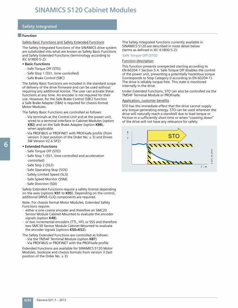
6 6
6/30 Siemens D21.7 – 2013
SINAMICS S120 Cabinet Modules
Function
Safety integrated
Safety Basic Functions and Safety Extended Functions
The Safety Integrated functions of the SINAMICS drive systemare subdivided into what are known as Safety Basic Functionsand Safety Extended Functions (terminology according toIEC 61800-5-2):• Basic Functions - Safe Torque Off (STO) - Safe Stop 1 (SS1, time-controlled) - Safe Brake Control (SBC)
The Safety Basic functions are included in the standard scopeof delivery of the drive firmware and can be used without requiring any additional license. The user can activate these functions at any time. An encoder is not required for their use. However, for the Safe Brake Control (SBC) function a Safe Brake Adapter (SBA) is required for chassis format Motor Modules.
The Safety Basic Functions are controlled as follows: - Via terminals at the Control Unit and at the power unit, wired to a terminal interface in Cabinet Modules (option K82) and on the Safe Brake Adapter (option K88), when applicable. - Via PROFIBUS or PROFINET with PROFIsafe profile (from version 3 (last position of the Order No. ≥ 3) and Drives SW Version V2.6 SP2)
• Extended Functions - Safe Torque Off (STO) - Safe Stop 1 (SS1, time-controlled and acceleration controlled) - Safe Stop 2 (SS2) - Safe Operating Stop (SOS) - Safely-Limited Speed (SLS) - Safe Speed Monitor (SSM) - Safe Direction (SDI)
Safety Extended Functions require a safety license dependingon the axes (options K01 to K05). Depending on the control, additional DRIVE-CLiQ components are required.
Note: For chassis format Motor Modules, Extended SafetyFunctions require:- either a sine-cosine encoder and therefore an SMC20 Sensor Module Cabinet-Mounted to evaluate the encoder signals (option K48).- or two incremental encoders (TTL, HTL or SSI) and therefore two SMC30 Sensor Module Cabinet-Mounted to evaluate the encoder signals (options K50+K52).
The Safety Extended Functions are controlled as follows: - Via the TM54F Terminal Module (option K87) - Via PROFIBUS or PROFINET with the PROFIsafe profile
Extended Functions are available for SINAMICS S120 MotorModules, booksize and chassis formats from version 3 (lastposition of the Order No. ≥ 3).
The Safety Integrated functions currently available inSINAMICS S120 are described in more detail below(terms as defined in IEC 61800-5-2):
Safe Torque Off (STO)
Function description
This function prevents unexpected starting according toEN 60204-1 Section 5.4. Safe Torque Off disables the control of the power unit, preventing a potentially hazardous torque (corresponds to Stop Category 0 according to EN 60204-1). The drive is reliably torque-free. This state is monitored internally in the drive.
Under Extended Functions, STO can also be controlled via theTM54F Terminal Module or PROFIsafe.
Application, customer benefits
STO has the immediate effect that the drive cannot supply any torque-generating energy. STO can be used wherever the drive will naturally reach a standstill due to load torque or friction in a sufficiently short time or when “coasting down” of the drive will not have any relevance for safety.
G_D
211_
XX
_002
10
t
v STO
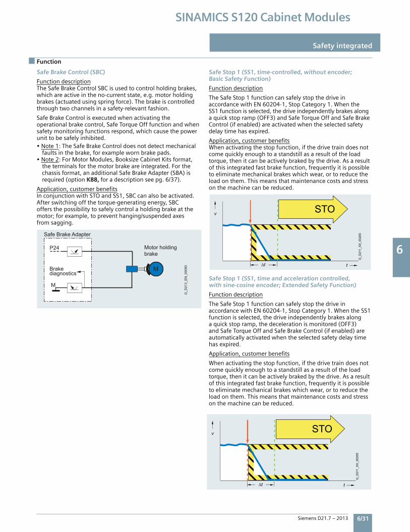
6 6
Siemens D21.7 – 2013 6/31
SINAMICS S120 Cabinet Modules
Safe Brake Control (SBC)
FunctiondescriptionTheSafeBrakeControlSBCisusedtocontrolholdingbrakes,whichareactiveintheno-currentstate,e.g.motorholdingbrakes(actuatedusingspringforce).Thebrakeiscontrolledthroughtwochannelsinasafety-relevantfashion.
SafeBrakeControlisexecutedwhenactivatingtheoperationalbrakecontrol,SafeTorqueOfffunctionandwhensafetymonitoringfunctionsrespond,whichcausethepowerunittobesafelyinhibited.•Note1:TheSafeBrakeControldoesnotdetectmechanical faultsinthebrake,forexamplewornbrakepads.•Note2:ForMotorModules,BooksizeCabinetKitsformat, theterminalsforthemotorbrakeareintegrated.Forthe chassisformat,anadditionalSafeBrakeAdapter(SBA)is required(optionK88,foradescriptionseepg.6/37).
Application,customerbenefitsInconjunctionwithSTOandSS1,SBCcanalsobeactivated.Afterswitchingoffthetorque-generatingenergy,SBCoffersthepossibilitytosafelycontrolaholdingbrakeatthemotor;forexample,topreventhanging/suspendedaxesfromsagging.
Safe Stop 1 (SS1, time-controlled, without encoder;Basic Safety Function)
Functiondescription
TheSafeStop1functioncansafelystopthedriveinaccordancewithEN60204-1,StopCategory1.WhentheSS1functionisselected,thedriveindependentlybrakesalongaquickstopramp(OFF3)andSafeTorqueOffandSafeBrakeControl(ifenabled)areactivatedwhentheselectedsafetydelaytimehasexpired.
Application,customerbenefitsWhenactivatingthestopfunction,ifthedrivetraindoesnotcomequicklyenoughtoastandstillasaresultoftheloadtorque,thenitcanbeactivelybrakedbythedrive.Asaresultofthisintegratedfastbrakefunction,frequentlyitispossibletoeliminatemechanicalbrakeswhichwear,ortoreducetheloadonthem.Thismeansthatmaintenancecostsandstressonthemachinecanbereduced.
Safe Stop 1 (SS1, time and acceleration controlled,with sine-cosine encoder; Extended Safety Function)
Functiondescription
TheSafeStop1functioncansafelystopthedriveinaccordancewithEN60204-1,StopCategory1.WhentheSS1functionisselected,thedriveindependentlybrakesalongaquickstopramp,thedecelerationismonitored(OFF3)andSafeTorqueOffandSafeBrakeControl(ifenabled)areautomaticallyactivatedwhentheselectedsafetydelaytimehasexpired.
Application,customerbenefits
Whenactivatingthestopfunction,ifthedrivetraindoesnotcomequicklyenoughtoastandstillasaresultoftheloadtorque,thenitcanbeactivelybrakedbythedrive.Asaresultofthisintegratedfastbrakefunction,frequentlyitispossibletoeliminatemechanicalbrakeswhichwear,ortoreducetheloadonthem.Thismeansthatmaintenancecostsandstressonthemachinecanbereduced.
Function
Safety integrated
∆t
v
t
G_D
211_
XX
_002
05
STO
G_D
213_
EN
_000
90Brake diagnostics
Motor holding brake
Safe Brake Adapter
M
M
P24
∆t
v
t
G_D
211_
XX
_002
05
STO
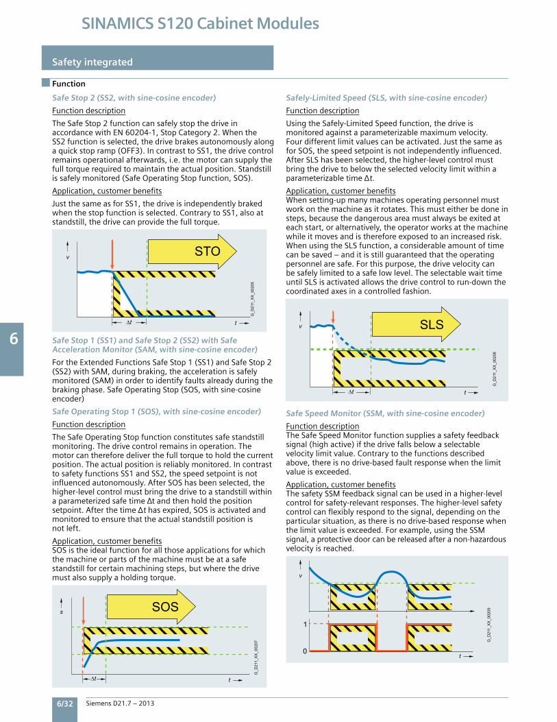
6 6
6/32 Siemens D21.7 – 2013
SINAMICS S120 Cabinet Modules
Function
Safety integrated
∆t
v
t
G_D
211_
XX
_002
05STO
G_D
211_
XX
_002
07
s
t
SOS
∆t
G_D
211_
XX
_002
08
SLS
t
v
∆t
t
G_D
211_
XX
_002
09
v
1
0
Safe Stop 2 (SS2, with sine-cosine encoder)
Functiondescription
TheSafeStop2functioncansafelystopthedriveinaccordancewithEN60204-1,StopCategory2.WhentheSS2functionisselected,thedrivebrakesautonomouslyalongaquickstopramp(OFF3).IncontrasttoSS1,thedrivecontrolremainsoperationalafterwards,i.e.themotorcansupplythefulltorquerequiredtomaintaintheactualposition.Standstillissafelymonitored(SafeOperatingStopfunction,SOS).
Application,customerbenefits
JustthesameasforSS1,thedriveisindependentlybrakedwhenthestopfunctionisselected.ContrarytoSS1,alsoatstandstill,thedrivecanprovidethefulltorque.
Safe Stop 1 (SS1) and Safe Stop 2 (SS2) with Safe Acceleration Monitor (SAM, with sine-cosine encoder)
FortheExtendedFunctionsSafeStop1(SS1)andSafeStop2(SS2)withSAM,duringbraking,theaccelerationissafelymonitored(SAM)inordertoidentifyfaultsalreadyduringthebrakingphase.SafeOperatingStop(SOS,withsine-cosineencoder)
Safe Operating Stop 1 (SOS), with sine-cosine encoder)
Functiondescription
TheSafeOperatingStopfunctionconstitutessafestandstillmonitoring.Thedrivecontrolremainsinoperation.Themotorcanthereforedeliverthefulltorquetoholdthecurrentposition.Theactualpositionisreliablymonitored.IncontrasttosafetyfunctionsSS1andSS2,thespeedsetpointisnotinfluencedautonomously.AfterSOShasbeenselected,thehigher-levelcontrolmustbringthedrivetoastandstillwithinaparameterizedsafetimeΔtandthenholdthepositionsetpoint.Afterthetime thasexpired,SOSisactivatedandmonitoredtoensurethattheactualstandstillpositionisnotleft.
Application,customerbenefitsSOSistheidealfunctionforallthoseapplicationsforwhichthemachineorpartsofthemachinemustbeatasafestandstillforcertainmachiningsteps,butwherethedrivemustalsosupplyaholdingtorque.
Safely-Limited Speed (SLS, with sine-cosine encoder)
Functiondescription
UsingtheSafely-LimitedSpeedfunction,thedriveismonitoredagainstaparameterizablemaximumvelocity.Fourdifferentlimitvaluescanbeactivated.JustthesameasforSOS,thespeedsetpointisnotindependentlyinfluenced.AfterSLShasbeenselected,thehigher-levelcontrolmustbringthedrivetobelowtheselectedvelocitylimitwithinaparameterizabletime t.
Application,customerbenefitsWhensetting-upmanymachinesoperatingpersonnelmustworkonthemachineasitrotates.Thismusteitherbedoneinsteps,becausethedangerousareamustalwaysbeexitedateachstart,oralternatively,theoperatorworksatthemachinewhileitmovesandisthereforeexposedtoanincreasedrisk.WhenusingtheSLSfunction,aconsiderableamountoftimecanbesaved–anditisstillguaranteedthattheoperatingpersonnelaresafe.Forthispurpose,thedrivevelocitycanbesafelylimitedtoasafelowlevel.TheselectablewaittimeuntilSLSisactivatedallowsthedrivecontroltorun-downthecoordinatedaxesinacontrolledfashion.
Safe Speed Monitor (SSM, with sine-cosine encoder)
FunctiondescriptionTheSafeSpeedMonitorfunctionsuppliesasafetyfeedbacksignal(highactive)ifthedrivefallsbelowaselectablevelocitylimitvalue.Contrarytothefunctionsdescribedabove,thereisnodrive-basedfaultresponsewhenthelimitvalueisexceeded.
Application,customerbenefitsThesafetySSMfeedbacksignalcanbeusedinahigher-levelcontrolforsafety-relevantresponses.Thehigher-levelsafetycontrolcanflexiblyrespondtothesignal,dependingontheparticularsituation,asthereisnodrive-basedresponsewhenthelimitvalueisexceeded.Forexample,usingtheSSMsignal,aprotectivedoorcanbereleasedafteranon-hazardousvelocityisreached.
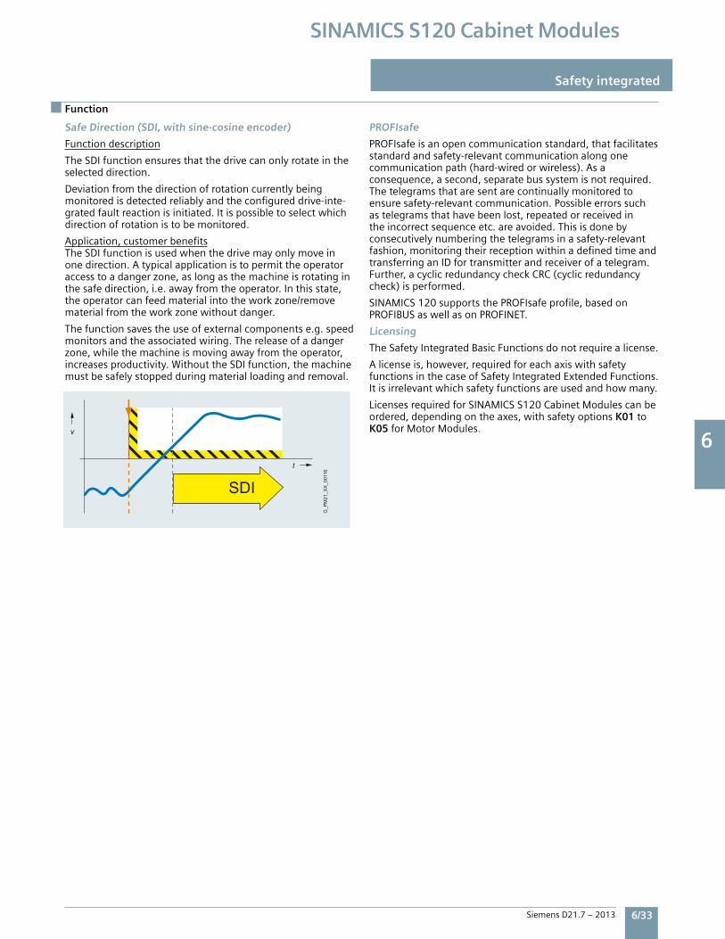
6 6
Siemens D21.7 – 2013 6/33
SINAMICS S120 Cabinet Modules
Safe Direction (SDI, with sine-cosine encoder)
Functiondescription
TheSDIfunctionensuresthatthedrivecanonlyrotateintheselecteddirection.
Deviationfromthedirectionofrotationcurrentlybeingmonitoredisdetectedreliablyandtheconfigureddrive-inte-gratedfaultreactionisinitiated.Itispossibletoselectwhichdirectionofrotationistobemonitored.
Application,customerbenefitsTheSDIfunctionisusedwhenthedrivemayonlymoveinonedirection.Atypicalapplicationistopermittheoperatoraccesstoadangerzone,aslongasthemachineisrotatinginthesafedirection,i.e.awayfromtheoperator.Inthisstate,theoperatorcanfeedmaterialintotheworkzone/removematerialfromtheworkzonewithoutdanger.
Thefunctionsavestheuseofexternalcomponentse.g.speedmonitorsandtheassociatedwiring.Thereleaseofadangerzone,whilethemachineismovingawayfromtheoperator,increasesproductivity.WithouttheSDIfunction,themachinemustbesafelystoppedduringmaterialloadingandremoval.
PROFIsafe
PROFIsafeisanopencommunicationstandard,thatfacilitatesstandardandsafety-relevantcommunicationalongonecommunicationpath(hard-wiredorwireless).Asaconsequence,asecond,separatebussystemisnotrequired.Thetelegramsthataresentarecontinuallymonitoredtoensuresafety-relevantcommunication.Possibleerrorssuchastelegramsthathavebeenlost,repeatedorreceivedintheincorrectsequenceetc.areavoided.Thisisdonebyconsecutivelynumberingthetelegramsinasafety-relevantfashion,monitoringtheirreceptionwithinadefinedtimeandtransferringanIDfortransmitterandreceiverofatelegram.Further,acyclicredundancycheckCRC(cyclicredundancycheck)isperformed.
SINAMICS120supportsthePROFIsafeprofile,basedonPROFIBUSaswellasonPROFINET.
Licensing
TheSafetyIntegratedBasicFunctionsdonotrequirealicense.
Alicenseis,however,requiredforeachaxiswithsafetyfunctionsinthecaseofSafetyIntegratedExtendedFunctions.Itisirrelevantwhichsafetyfunctionsareusedandhowmany.
LicensesrequiredforSINAMICSS120CabinetModulescanbeordered,dependingontheaxes,withsafetyoptionsK01toK05forMotorModules.
Function
Safety integrated
G_P
M21
_XX
_001
16
v
t
SDI
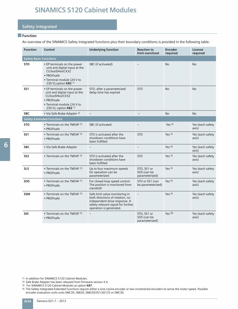
6 6
6/34 Siemens D21.7 – 2013
SINAMICS S120 Cabinet Modules
AnoverviewoftheSINAMICSSafetyIntegratedfunctionsplustheirboundaryconditionsisprovidedinthefollowingtable.
Function Control Underlying function Reaction to limit overshoot
Encoderrequired
Licenserequired
Safety Basic Functions
STO •EPterminalsonthepowerunitanddigitalinputattheCU3xx/D4xx/CX32•PROFIsafe•Terminalmodule(24Vto230V),optionK821)
SBC(ifactivated) – No No
SS1 •EPterminalsonthepowerunitanddigitalinputattheCU3xx/D4xx/CX32•PROFIsafe•Terminalmodule(24Vto230V),optionK821)
STO,afteraparameterizeddelaytimehasexpired
STO No No
SBC •ViaSafeBrakeAdapter2) – – No No
Safety Extended Functions
STO •TerminalsontheTM54F3)
•PROFIsafeSBC(ifactivated – Yes4) Yes(eachsafety
axis)
SS1 •TerminalsontheTM54F3)
•PROFIsafeSTOisactivatedaftertheshutdownconditionshavebeenfulfilled
STO Yes4) Yes(eachsafetyaxis)
SBC •ViaSafeBrakeAdapter – – Yes4) Yes(eachsafetyaxis)
SS2 •TerminalsontheTM54F3) STOisactivatedaftertheshutdownconditionshavebeenfulfilled
STO Yes4) Yes(eachsafetyaxis)
SLS •TerminalsontheTM54F3)
•PROFIsafeUptofourmaximumspeedsforoperationcanbeparameterized
STO,SS1orSOS(canbeparameterized)
Yes4) Yes(eachsafetyaxis)
SOS •TerminalsontheTM54F3)
•PROFIsafeForclosed-loopspeedcontrol:Thepositionismonitoredfromstandstill
STOorSS1(canbeparameterized)
Yes4) Yes(eachsafetyaxis)
SSM •TerminalsontheTM54F3)
•PROFIsafeSafelimitvaluemonitoringinbothdirectionsofrotation,noindependentdriveresponse.Asafety-relevantsignalforfurtheroperationisgenerated.
– Yes4) Yes(eachsafetyaxis)
SDI •TerminalsontheTM54F3)
•PROFIsafe– STO,SS1or
SOS(canbeparameterized)
Yes4) Yes(eachsafetyaxis)
1) InadditionforSINAMICSS120CabinetModules.2)SafeBrakeAdapterhasbeenreleasedfromfirmwareversion4.4.3)ForSINAMICSS120CabinetModulesasoptionK87.4)TheSafetyIntegratedExtendedFunctionsrequireeitherasine-cosineencoderortwoincrementalencoderstosensethemotorspeed.Possible encoderevaluationunitsunitsSMC20,SMI20,SME20/25/120/125orSMC30.
Function
Safety integrated
6 6
Siemens D21.7 – 2013 6/35
SINAMICS S120 Cabinet Modules
The principle of operation of Safety Integrated
Two independent shutdown paths
There are two shutdown paths that are independent of oneanother.
All shutdown paths are low active. This therefore ensures thatwhen a component fails or there is a wire break, then the system always goes into the safe state. When a fault is detected in the shutdown paths, the Safe Torque Off or Safe Stop 1 function (depending on the parameterization, also refer to the table on the Page 3/13) is activated and a restart is prevented.
Two-channel monitoring structure
All of the hardware and software functions important for Safety Integrated are implemented in two independent monitoring channels (e.g. shutdown paths, data management, data comparison). The safety-relevant data in the two monitoring channels is cyclically compared crosswise.
The monitoring functions in each monitoring channel are based on the principle that before a particular action, there must be a defined state, and after the action there must be a specific feedback. If this expectation is not fulfilled in a monitoring channel, then the drive is shutdown through two channels and the appropriate signal output.
Forced checking procedure using a test stopIn order to fulfill the requirements of ISO 13849-1 (previously EN 954-1) and IEC 61508 regarding early fault detection, the functions and the shutdown paths must be tested within a specific time period at least once to ensure that they are operating correctly. This must be realized either cyclically and manually or the test stop must be automatically initiated as part of the process.
The test stop cycle is monitored, and after a specific timehas been exceeded, an alarm is output.
A test stop does not require a power on. The acknowledgment is realized when deselecting the test stop request. When the machine is operational, it can be assumed that there is no risk for personnel as a result of the appropriate safety equipment (e.g. protective doors). As a consequence, the user is only made aware of the forced checking procedure that is required using an alarm, and is requested to perform the forced checking procedure at the next possible opportunity.
Examples for performing the forced checking procedure:• When the drives are stationary after switching-on the system• Before opening the protective door• In a specified rhythm (e.g. every 8 hours)• In the automatic mode, time and event-triggered
Function
Safety integrated Safety integrated
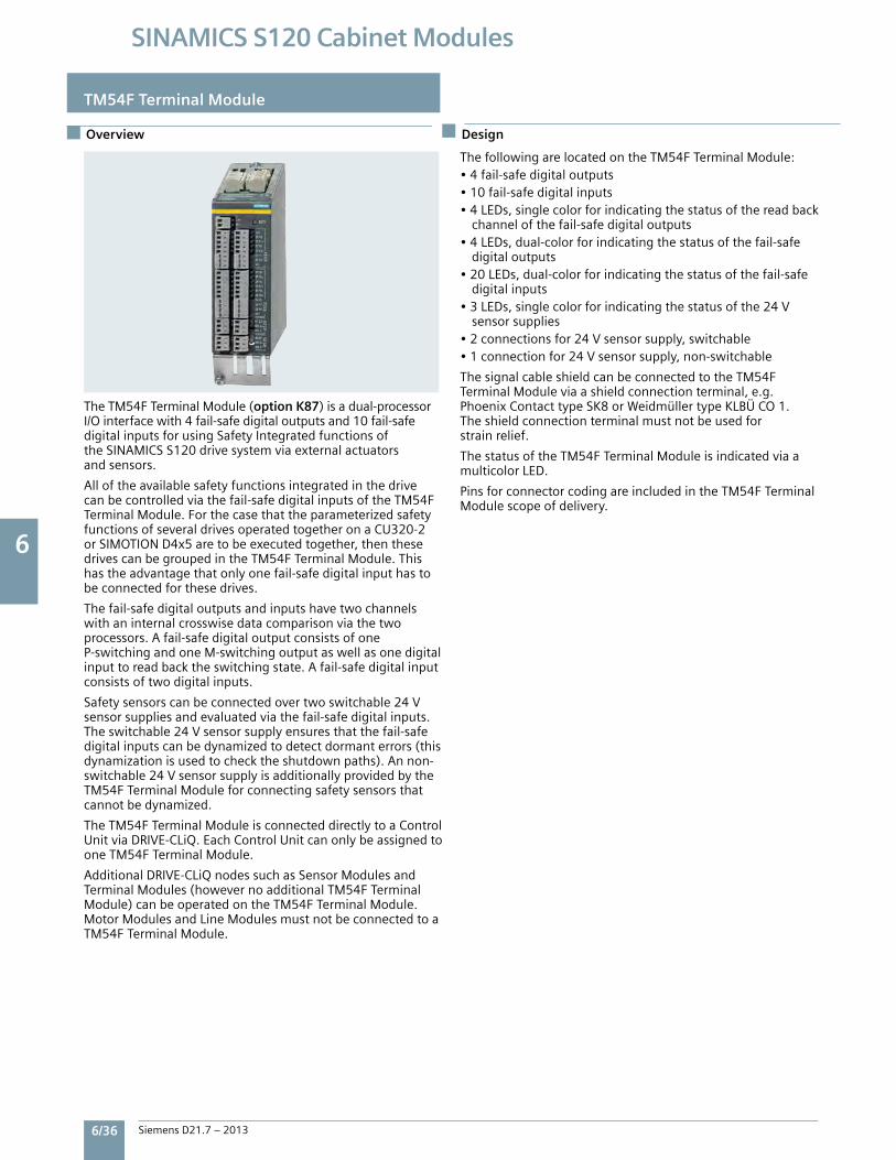
6 6
6/36 Siemens D21.7 – 2013
SINAMICS S120 Cabinet Modules
Overview
TM54F Terminal Module
Design
TheTM54FTerminalModule(option K87)isadual-processorI/Ointerfacewith4fail-safedigitaloutputsand10fail-safedigitalinputsforusingSafetyIntegratedfunctionsoftheSINAMICSS120drivesystemviaexternalactuatorsandsensors.
Alloftheavailablesafetyfunctionsintegratedinthedrivecanbecontrolledviathefail-safedigitalinputsoftheTM54FTerminalModule.ForthecasethattheparameterizedsafetyfunctionsofseveraldrivesoperatedtogetheronaCU320-2orSIMOTIOND4x5aretobeexecutedtogether,thenthesedrivescanbegroupedintheTM54FTerminalModule.Thishastheadvantagethatonlyonefail-safedigitalinputhastobeconnectedforthesedrives.
Thefail-safedigitaloutputsandinputshavetwochannelswithaninternalcrosswisedatacomparisonviathetwoprocessors.Afail-safedigitaloutputconsistsofoneP-switchingandoneM-switchingoutputaswellasonedigitalinputtoreadbacktheswitchingstate.Afail-safedigitalinputconsistsoftwodigitalinputs.
Safetysensorscanbeconnectedovertwoswitchable24Vsensorsuppliesandevaluatedviathefail-safedigitalinputs.Theswitchable24Vsensorsupplyensuresthatthefail-safedigitalinputscanbedynamizedtodetectdormanterrors(thisdynamizationisusedtochecktheshutdownpaths).Annon-switchable24VsensorsupplyisadditionallyprovidedbytheTM54FTerminalModuleforconnectingsafetysensorsthatcannotbedynamized.
TheTM54FTerminalModuleisconnecteddirectlytoaControlUnitviaDRIVE-CLiQ.EachControlUnitcanonlybeassignedtooneTM54FTerminalModule.
AdditionalDRIVE-CLiQnodessuchasSensorModulesandTerminalModules(howevernoadditionalTM54FTerminalModule)canbeoperatedontheTM54FTerminalModule.MotorModulesandLineModulesmustnotbeconnectedtoaTM54FTerminalModule.
ThefollowingarelocatedontheTM54FTerminalModule:•4fail-safedigitaloutputs•10fail-safedigitalinputs•4LEDs,singlecolorforindicatingthestatusofthereadback channelofthefail-safedigitaloutputs•4LEDs,dual-colorforindicatingthestatusofthefail-safe digitaloutputs•20LEDs,dual-colorforindicatingthestatusofthefail-safe digitalinputs•3LEDs,singlecolorforindicatingthestatusofthe24V sensorsupplies•2connectionsfor24Vsensorsupply,switchable•1connectionfor24Vsensorsupply,non-switchable
ThesignalcableshieldcanbeconnectedtotheTM54FTerminalModuleviaashieldconnectionterminal,e.g.PhoenixContacttypeSK8orWeidmüllertypeKLBÜCO1.Theshieldconnectionterminalmustnotbeusedforstrainrelief.
ThestatusoftheTM54FTerminalModuleisindicatedviaamulticolorLED.
PinsforconnectorcodingareincludedintheTM54FTerminalModulescopeofdelivery.
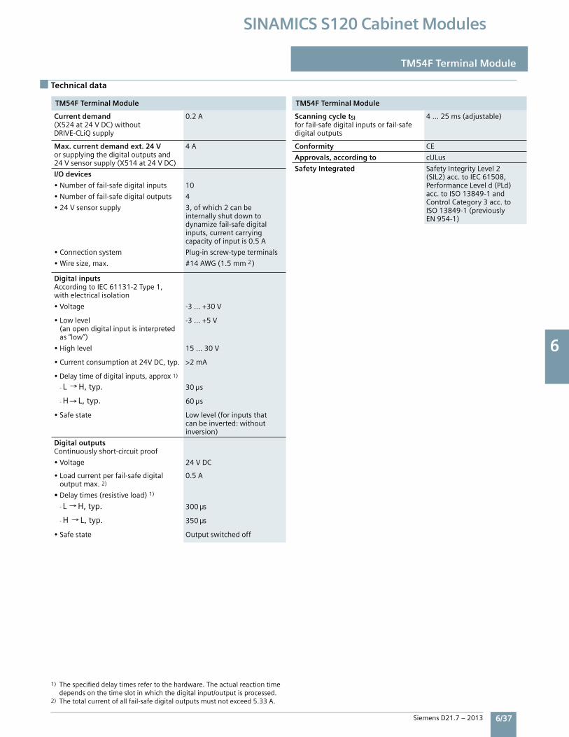
6 6
Siemens D21.7 – 2013 6/37
SINAMICS S120 Cabinet Modules
Technical data
TM54F Terminal Module TM54F Terminal Module
TM54F Terminal Module
Current demand(X524at24VDC)withoutDRIVE-CLiQsupply
0.2A
Max. current demand ext. 24 Vorsupplyingthedigitaloutputsand24Vsensorsupply(X514at24VDC)
4A
I/O devices
•Numberoffail-safedigitalinputs 10
•Numberoffail-safedigitaloutputs 4
•24Vsensorsupply 3,ofwhich2canbeinternallyshutdowntodynamizefail-safedigitalinputs,currentcarryingcapacityofinputis0.5A
•Connectionsystem Plug-inscrew-typeterminals
•Wiresize,max. #14AWG(1.5mm2)
Digital inputsAccordingtoIEC61131-2Type1,withelectricalisolation
•Voltage -3...+30V
•Lowlevel(anopendigitalinputisinterpretedas“low”)
-3...+5V
•Highlevel 15...30V
•Currentconsumptionat24VDC,typ. >2mA
•Delaytimeofdigitalinputs,approx1)
-L H,typ. 30 s
-H L,typ. 60 s
•Safestate Lowlevel(forinputsthatcanbeinverted:withoutinversion)
Digital outputsContinuouslyshort-circuitproof
•Voltage 24VDC
•Loadcurrentperfail-safedigitaloutputmax.2)
0.5A
• Delaytimes(resistiveload)1)
-L H,typ. 300 s
-H L,typ. 350 s
•Safestate Outputswitchedoff
TM54F Terminal Module
Scanning cycle tSIforfail-safedigitalinputsorfail-safedigitaloutputs
4...25ms(adjustable)
Conformity CE
Approvals, according to cULus
Safety Integrated SafetyIntegrityLevel2(SIL2)acc.toIEC61508,PerformanceLeveld(PLd)acc.toISO13849-1andControlCategory3acc.toISO13849-1(previouslyEN954-1)
1)Thespecifieddelaytimesrefertothehardware.Theactualreactiontimedependsonthetimeslotinwhichthedigitalinput/outputisprocessed.2)Thetotalcurrentofallfail-safedigitaloutputsmustnotexceed5.33A.
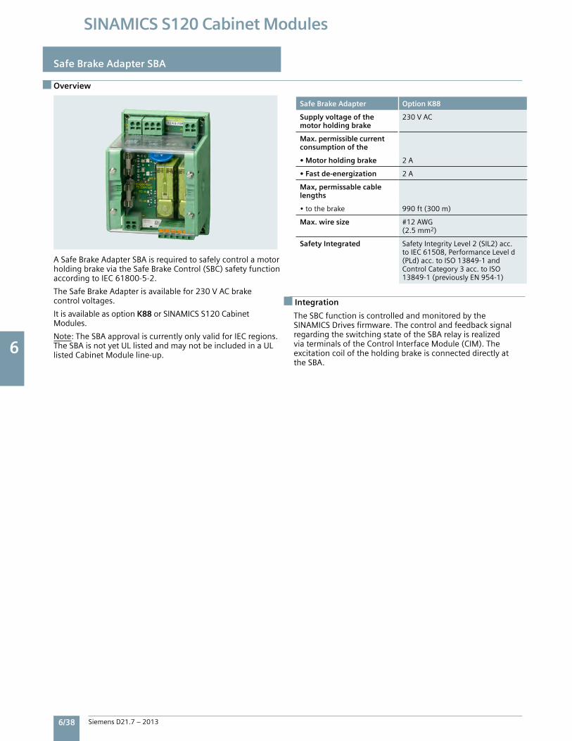
6 6
6/38 Siemens D21.7 – 2013
SINAMICS S120 Cabinet Modules
Overview
Safe Brake Adapter SBA
Safe Brake Adapter Option K88
Supply voltage of the motor holding brake
230VAC
Max. permissible currentconsumption of the
• Motor holding brake 2A
• Fast de-energization 2A
Max, permissable cable lengths
•tothebrake 990ft(300m)
Max. wire size #12AWG(2.5mm2)
Safety Integrated SafetyIntegrityLevel2(SIL2)acc.toIEC61508,PerformanceLeveld(PLd)acc.toISO13849-1andControlCategory3acc.toISO13849-1(previouslyEN954-1)
Integration
ASafeBrakeAdapterSBAisrequiredtosafelycontrolamotorholdingbrakeviatheSafeBrakeControl(SBC)safetyfunctionaccordingtoIEC61800-5-2.
TheSafeBrakeAdapterisavailablefor230VACbrakecontrolvoltages.
ItisavailableasoptionK88 orSINAMICSS120CabinetModules.
Note:TheSBAapprovaliscurrentlyonlyvalidforIECregions.TheSBAisnotyetULlistedandmaynotbeincludedinaULlistedCabinetModuleline-up.
TheSBCfunctioniscontrolledandmonitoredbytheSINAMICSDrivesfirmware.ThecontrolandfeedbacksignalregardingtheswitchingstateoftheSBArelayisrealizedviaterminalsoftheControlInterfaceModule(CIM).TheexcitationcoiloftheholdingbrakeisconnecteddirectlyattheSBA.
5
SINAMICS S120 Cabinet ModulesEngineering Tools, Service & Support
7/2 Engineering software SizerforSiemensdrives STArTercommissioningtool DriveControlChart
7/6 Service & Support Servicetoolforexchangingpowerblocks Spareparts Completelifecycleservices Service&Supportcontacts
7
SiemensD21.7–2013
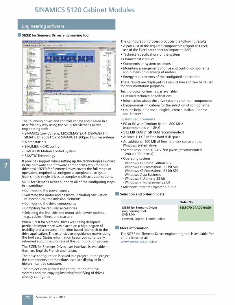
7
7/2 Siemens D21.7 – 2013
SINAMICS S120 Cabinet Modules
SIZER for Siemens Drives engineering tool
Engineering software
Thefollowingdrivesandcontrolscanbeengineeredinauser-friendlywayusingtheSizerforSiemensDrivesengineeringtool:•SiNAMiCSLowVoltage,MiCrOMASTer4,DYNAVerTT, SiMATiCeT200SFCandSiMATiCeT200proFCdrivesystems•Motorstarters•SiNUMeriKCNCcontrol•SiMOTiONMotionControlSystem•SiMATiCTechnology
itprovidessupportwhensettingupthetechnologiesinvolvedinthehardwareandfirmwarecomponentsrequiredforadrivetask.SizerforSiemensDrivescoversthefullrangeofoperationsrequiredtoconfigureacompletedrivesystem,fromsimplesingledrivestocomplexmulti-axisapplications.
SizerforSiemensDrivessupportsalloftheconfiguringstepsinaworkflow:•Configuringthepowersupply•Selectingthemotorandgearbox,includingcalculation ofmechanicaltransmissionelements•Configuringthedrivecomponents•Compilingtherequiredaccessories•Selectingtheline-sideandmotor-sidepoweroptions, e.g.,cables,filters,andreactors
WhenSizerforSiemensDriveswasbeingdesigned,particularimportancewasplacedonahighdegreeofusabilityandauniversal,function-basedapproachtothedriveapplication.Theextensiveuserguidancemakesusingthetooleasy.Statusinformationkeepsyoucontinuallyinformedabouttheprogressoftheconfigurationprocess.
TheSizerforSiemensDrivesuserinterfaceisavailableinGerman,english,Frenchanditalian.
Thedriveconfigurationissavedinaproject.intheproject,thecomponentsandfunctionsusedaredisplayedinahierarchicaltreestructure.
Theprojectviewpermitstheconfigurationofdrivesystemsandthecopying/inserting/modifyingofdrivesalreadyconfigured.
Theconfigurationprocessproducesthefollowingresults:•Apartslistoftherequiredcomponents(exporttoexcel, useoftheexceldatasheetforimporttoSAP)•Technicalspecificationsofthesystem•Characteristiccurves•Commentsonsystemreactions•Mountingarrangementofdriveandcontrolcomponents anddimensiondrawingsofmotors•energyrequirementsoftheconfiguredapplication
Theseresultsaredisplayedinaresultstreeandcanbereusedfordocumentationpurposes.
Technologicalonlinehelpisavailable:•Detailedtechnicalspecifications•informationaboutthedrivesystemsandtheircomponents•Decision-makingcriteriafortheselectionofcomponents•OnlinehelpinGerman,english,French,italian,Chinese andJapanese
System requirements•PGorPCwithPentiumiiimin.800MHz (recommended>1GHz)•512MBrAM(1GBrAMrecommended)•Atleast4.1GBoffreeharddiskspace•Anadditional100MBoffreeharddiskspaceonthe Windowssystemdrive•Screenresolution1024×768pixels(recommended 1280×1024pixels)•Operatingsystem -WindowsXPHomeeditionSP2 -WindowsXPProfessional32bitSP2 -WindowsXPProfessional64bitSP2 -WindowsVistaBusiness -Windows7Ultimate32bit -Windows7Professional32bit•Microsoftinternetexplorer5.5SP2
Order No.
SIZER for Siemens Drivesengineering toolDVD-rOMGerman,english,French,italian
6SL3070-0AA00-0AG0
TheSizerforSiemensDrivesengineeringtoolisavailablefreeontheinternetat:www.siemens.com/sizer
Selection and ordering data
More information
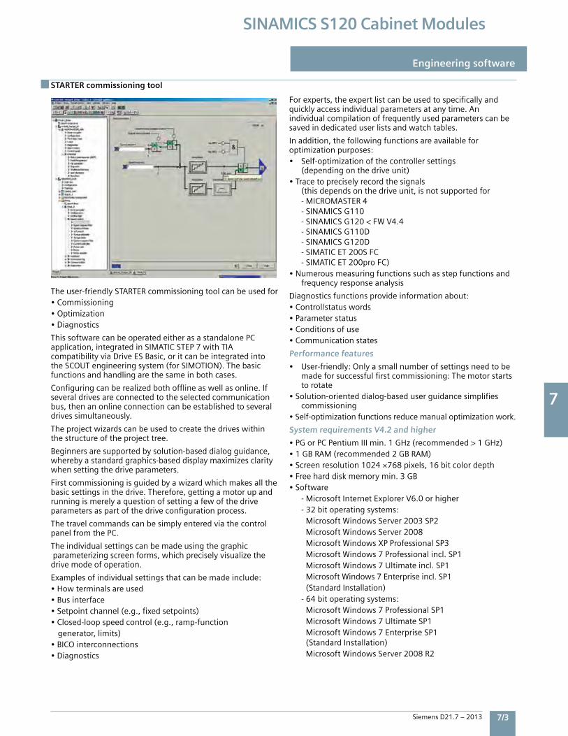
7
Siemens D21.7 – 2013 7/3
SINAMICS S120 Cabinet Modules
STARTER commissioning tool
Engineering software
Theuser-friendlySTArTercommissioningtoolcanbeusedfor•Commissioning•Optimization•Diagnostics
ThissoftwarecanbeoperatedeitherasastandalonePCapplication,integratedinSiMATiCSTeP7withTiAcompatibilityviaDriveeSBasic,oritcanbeintegratedintotheSCOUTengineeringsystem(forSiMOTiON).Thebasicfunctionsandhandlingarethesameinbothcases.
Configuringcanberealizedbothofflineaswellasonline.ifseveraldrivesareconnectedtotheselectedcommunicationbus,thenanonlineconnectioncanbeestablishedtoseveraldrivessimultaneously.
Theprojectwizardscanbeusedtocreatethedriveswithinthestructureoftheprojecttree.
Beginnersaresupportedbysolution-baseddialogguidance,wherebyastandardgraphics-baseddisplaymaximizesclaritywhensettingthedriveparameters.
Firstcommissioningisguidedbyawizardwhichmakesallthebasicsettingsinthedrive.Therefore,gettingamotorupandrunningismerelyaquestionofsettingafewofthedriveparametersaspartofthedriveconfigurationprocess.
ThetravelcommandscanbesimplyenteredviathecontrolpanelfromthePC.
Theindividualsettingscanbemadeusingthegraphicparameterizingscreenforms,whichpreciselyvisualizethedrivemodeofoperation.
examplesofindividualsettingsthatcanbemadeinclude:•Howterminalsareused•Businterface•Setpointchannel(e.g.,fixedsetpoints)•Closed-loopspeedcontrol(e.g.,ramp-functiongenerator,limits)•BiCOinterconnections•Diagnostics
Forexperts,theexpertlistcanbeusedtospecificallyandquicklyaccessindividualparametersatanytime.Anindividualcompilationoffrequentlyusedparameterscanbesavedindedicateduserlistsandwatchtables.
inaddition,thefollowingfunctionsareavailableforoptimizationpurposes:• Self-optimizationofthecontrollersettings (dependingonthedriveunit)•Tracetopreciselyrecordthesignals (thisdependsonthedriveunit,isnotsupportedfor -MiCrOMASTer4 -SiNAMiCSG110 -SiNAMiCSG120<FWV4.4 -SiNAMiCSG110D -SiNAMiCSG120D -SiMATiCeT200SFC -SiMATiCeT200proFC)•Numerousmeasuringfunctionssuchasstepfunctionsand frequencyresponseanalysis
Diagnosticsfunctionsprovideinformationabout:•Control/statuswords•Parameterstatus•Conditionsofuse•Communicationstates
Performance features
• User-friendly:Onlyasmallnumberofsettingsneedtobe madeforsuccessfulfirstcommissioning:Themotorstarts torotate•Solution-orienteddialog-baseduserguidancesimplifies commissioning•Self-optimizationfunctionsreducemanualoptimizationwork.
System requirements V4.2 and higher
•PGorPCPentiumiiimin.1GHz(recommended>1GHz)•1GBrAM(recommended2GBrAM)•Screenresolution1024×768pixels,16bitcolordepth•Freeharddiskmemorymin.3GB•Software -MicrosoftinternetexplorerV6.0orhigher -32bitoperatingsystems: MicrosoftWindowsServer2003SP2 MicrosoftWindowsServer2008 MicrosoftWindowsXPProfessionalSP3 MicrosoftWindows7Professionalincl.SP1 MicrosoftWindows7Ultimateincl.SP1 MicrosoftWindows7enterpriseincl.SP1 (Standardinstallation) -64bitoperatingsystems: MicrosoftWindows7ProfessionalSP1 MicrosoftWindows7UltimateSP1 MicrosoftWindows7enterpriseSP1 (Standardinstallation) MicrosoftWindowsServer2008r2
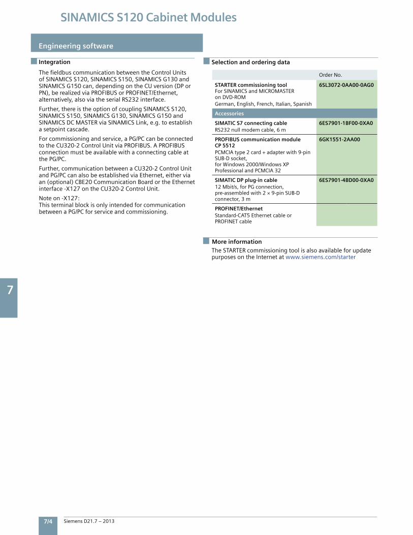
7
7/4 Siemens D21.7 – 2013
SINAMICS S120 Cabinet Modules
Integration
Engineering software
TheSTArTercommissioningtoolisalsoavailableforupdatepurposesontheinternetatwww.siemens.com/starter
ThefieldbuscommunicationbetweentheControlUnitsofSiNAMiCSS120,SiNAMiCSS150,SiNAMiCSG130andSiNAMiCSG150can,dependingontheCUversion(DPorPN),berealizedviaPrOFiBUSorPrOFiNeT/ethernet,alternatively,alsoviatheserialrS232interface.
Further,thereistheoptionofcouplingSiNAMiCSS120,SiNAMiCSS150,SiNAMiCSG130,SiNAMiCSG150andSiNAMiCSDCMASTerviaSiNAMiCSLink,e.g.toestablishasetpointcascade.
Forcommissioningandservice,aPG/PCcanbeconnectedtotheCU320-2ControlUnitviaPrOFiBUS.APrOFiBUSconnectionmustbeavailablewithaconnectingcableatthePG/PC.
Further,communicationbetweenaCU320-2ControlUnitandPG/PCcanalsobeestablishedviaethernet,eitherviaan(optional)CBe20CommunicationBoardortheethernetinterface-X127ontheCU320-2ControlUnit.
Noteon-X127:ThisterminalblockisonlyintendedforcommunicationbetweenaPG/PCforserviceandcommissioning.
Selection and ordering data
OrderNo.
STARTER commissioning toolForSiNAMiCSandMiCrOMASTeronDVD-rOMGerman,english,French,italian,Spanish
6SL3072-0AA00-0AG0
Accessories
SIMATIC S7 connecting cablerS232nullmodemcable,6m
6ES7901-1BF00-0XA0
PROFIBUS communication moduleCP 5512PCMCiAtype2card+adapterwith9-pinSUB-Dsocket,forWindows2000/WindowsXPProfessionalandPCMCiA32
6GK1551-2AA00
SIMATIC DP plug-in cable12Mbit/s,forPGconnection,pre-assembledwith2×9-pinSUB-Dconnector,3m
6ES7901-4BD00-0XA0
PROFINET/EthernetStandard-CAT5ethernetcableorPrOFiNeTcable
More information
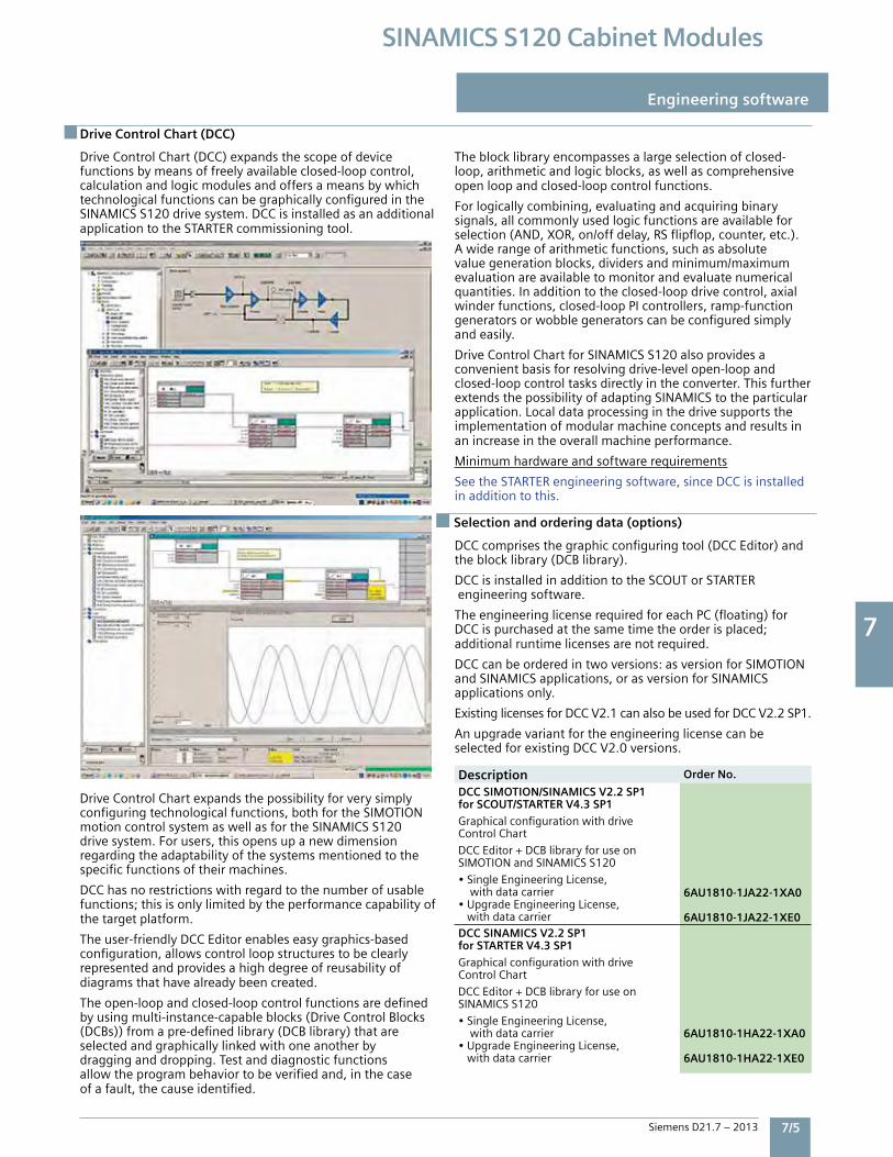
7
Siemens D21.7 – 2013 7/5
SINAMICS S120 Cabinet Modules
Drive Control Chart (DCC)
Engineering software
DriveControlChart(DCC)expandsthescopeofdevicefunctionsbymeansoffreelyavailableclosed-loopcontrol,calculationandlogicmodulesandoffersameansbywhichtechnologicalfunctionscanbegraphicallyconfiguredintheSiNAMiCSS120drivesystem.DCCisinstalledasanadditionalapplicationtotheSTArTercommissioningtool.
DriveControlChartexpandsthepossibilityforverysimplyconfiguringtechnologicalfunctions,bothfortheSiMOTiONmotioncontrolsystemaswellasfortheSiNAMiCSS120drivesystem.Forusers,thisopensupanewdimensionregardingtheadaptabilityofthesystemsmentionedtothespecificfunctionsoftheirmachines.
DCChasnorestrictionswithregardtothenumberofusablefunctions;thisisonlylimitedbytheperformancecapabilityofthetargetplatform.
Theuser-friendlyDCCeditorenableseasygraphics-basedconfiguration,allowscontrolloopstructurestobeclearlyrepresentedandprovidesahighdegreeofreusabilityofdiagramsthathavealreadybeencreated.
Theopen-loopandclosed-loopcontrolfunctionsaredefinedbyusingmulti-instance-capableblocks(DriveControlBlocks(DCBs))fromapre-definedlibrary(DCBlibrary)thatareselectedandgraphicallylinkedwithoneanotherbydragginganddropping.Testanddiagnosticfunctionsallowtheprogrambehaviortobeverifiedand,inthecaseofafault,thecauseidentified.
Theblocklibraryencompassesalargeselectionofclosed-loop,arithmeticandlogicblocks,aswellascomprehensiveopenloopandclosed-loopcontrolfunctions.
Forlogicallycombining,evaluatingandacquiringbinarysignals,allcommonlyusedlogicfunctionsareavailableforselection(AND,XOr,on/offdelay,rSflipflop,counter,etc.).Awiderangeofarithmeticfunctions,suchasabsolutevaluegenerationblocks,dividersandminimum/maximumevaluationareavailabletomonitorandevaluatenumericalquantities.inadditiontotheclosed-loopdrivecontrol,axialwinderfunctions,closed-loopPicontrollers,ramp-functiongeneratorsorwobblegeneratorscanbeconfiguredsimplyandeasily.
DriveControlChartforSiNAMiCSS120alsoprovidesaconvenientbasisforresolvingdrive-levelopen-loopandclosed-loopcontroltasksdirectlyintheconverter.ThisfurtherextendsthepossibilityofadaptingSiNAMiCStotheparticularapplication.Localdataprocessinginthedrivesupportstheimplementationofmodularmachineconceptsandresultsinanincreaseintheoverallmachineperformance.
Minimumhardwareandsoftwarerequirements
SeetheSTArTerengineeringsoftware,sinceDCCisinstalledinadditiontothis.
DCCcomprisesthegraphicconfiguringtool(DCCeditor)andtheblocklibrary(DCBlibrary).
DCCisinstalledinadditiontotheSCOUTorSTArTerengineeringsoftware.
TheengineeringlicenserequiredforeachPC(floating)forDCCispurchasedatthesametimetheorderisplaced;additionalruntimelicensesarenotrequired.
DCCcanbeorderedintwoversions:asversionforSiMOTiONandSiNAMiCSapplications,orasversionforSiNAMiCSapplicationsonly.
existinglicensesforDCCV2.1canalsobeusedforDCCV2.2SP1.
AnupgradevariantfortheengineeringlicensecanbeselectedforexistingDCCV2.0versions.
Description Order No.
DCC SIMOTION/SINAMICS V2.2 SP1for SCOUT/STARTER V4.3 SP1
GraphicalconfigurationwithdriveControlChart
DCCeditor+DCBlibraryforuseonSiMOTiONandSiNAMiCSS120
•SingleengineeringLicense, withdatacarrier•UpgradeengineeringLicense, withdatacarrier
6AU1810-1JA22-1XA0
6AU1810-1JA22-1XE0DCC SINAMICS V2.2 SP1for STARTER V4.3 SP1
GraphicalconfigurationwithdriveControlChart
DCCeditor+DCBlibraryforuseonSiNAMiCSS120
•SingleengineeringLicense, withdatacarrier•UpgradeengineeringLicense, withdatacarrier
6AU1810-1HA22-1XA0
6AU1810-1HA22-1XE0
Selection and ordering data (options)
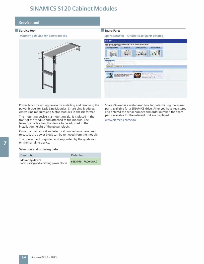
7
7/6 Siemens D21.7 – 2013
SINAMICS S120 Cabinet Modules
Service tool
Service tool
Power block mounting device for installing and removing the power blocks for Basic Line Modules, Smart Line Modules, Active Line modules and Motor Modules in chassis format.
The mounting device is a mounting aid. It is placed in the front of the module and attached to the module. The telescopic rails allow the device to be adjusted to the installation height of the power blocks.
Once the mechanical and electrical connections have been released, the power block can be removed from the module.
The power block is guided and supported by the guide rails on the handling device.
Selection and ordering data
Description Order No.
Mounting devicefor installing and removing power blocks 6SL3766-1FA00-0AA0
SparesOnWeb is a web-based tool for determining the spare parts available for a SINAMICS drive. After you have registered and entered the serial number and order number, the spare parts available for the relevant unit are displayed.
www.siemens.com/sow
SparesOnWeb – Online spart parts catalogMounting device for power blocks
Spare Parts
7
Siemens D21.7 – 2013 7/7
SINAMICS S120 Cabinet Modules
Service & Support
Complete life cycle service
For machine constructors, solution providers and plant operators: The service offering from Siemens industry, Automation and Drive Technologies includes comprehensive services for a wide range of different users in all sectors of the manufacturing and process industry.
To accompany our products and systems, we offer integrated and structured services that provide valuable support in every phase of the life cycle of your machine or plant – from planning and implementation through commissioning as far as maintenance and modernization.
Our Service & Support accompanies you worldwide in all matters concerning automation and drives from Siemens. We provide direct on-site support in more than 100 countries through all phases of the life cycle of your machines and plants.
You have an experienced team of specialists at your side to provide active support and bundled know-how. Regular training courses and intensive contact among our employees – even across continents – ensure reliable service in the most diverse areas.
Service & Support Contacts
Pre-sales Support, Order EntryPlease contact your local sales office.GA400 facility, Alpharetta, GA Phone: (770) 740-3000 e-mail: [email protected]
Technical SupportInside USA, toll free: 1-800-333-7421 Outside USA: +1(423)262-5710Online request: www.siemens.com/automation/support-request
Customer Service, Field Services, Spare Parts & RepairInside USA, toll free: 1-800-241-4453 Outside USA: +1(423)262-5711 e-mail: [email protected]
Training Start-up and maintenance training Siemens Industry offers the following course for SINAMICS S120:Course name: SINAMICS S Setup & Maintenance Course code: SCT-DVSNAM1ADuration: 4¹⁄₂ Days
This course provides training on Siemens’ SINAMICS S drive systems family. Student will gain experience necessary to setup and maintain the operation of the SINAMICS S. The course includes an analysis of required hardware, steps for a quick startup, as well as additional application dependent steps for configuration, tuning and troubleshooting. A working knowledge of the drive communications capabilities will also be presented. The course also covers the extensive diagnostic capabilities of the drive.
Please see the Siemens Industry SITRAIN Internet site for dates and costs of scheduled classes at:http://www.usa.siemens.com/training

Siemens Industry, Inc. 3333 Old Milton Parkway Alpharetta, GA 30005 1-800-241-4453 [email protected]
Subject to change without prior notice.Order No: DRCA-D2171-0313 All rights reserved. Printed in USA. ©2013 Siemens Industry, Inc.
The information provided in this brochure contains merely general descriptions or characteristics of performance which in case of actual use do not always apply as described or which may change as a result of further development of the products. An obligation to provide the respectivecharacteristics shall only exist if expressly agreed in the terms of contract.
Siemens is a registered trademark of Siemens AG. Product names mentioned may be trademarks or registered trademarks of their respective companies. Specificationsare subject to change without notice.www.usa.siemens.com/drives