Embed Size (px)
Citation preview
Functional Example MC-FE-I-005-V11-EN
SINAMICS S120 Safety Integrated Extended Functions
Fail-Safe Drives Controlling the CU320 from a TM54F and F-CPU
SINAMICS S120 Fail-Safe Drives Entry ID: 28424136
A&D Safety Integrated Page 2/42 MC-FE-I-005-V11-EN
Cop
yrig
ht ©
Sie
men
s A
G 2
008
All
right
s re
serv
ed
2842
4136
_mc_
fe_i
_005
_v11
_en_
_S12
0_C
U32
0_TM
54F.
doc
Preliminary remark The Functional Examples dealing with “Safety Integrated” are fully functional and tested automation configurations based on A&D stan-dard products for simple, fast and inexpensive implementation of automation tasks in safety engineering. Each of these Functional Ex-amples covers a frequently occurring subtask of a typical customer problem in safety engineering. Aside from a list of all required software and hardware components and a description of the way they are connected to each other, the Functional Examples include the tested and commented code. This ensures that the functionalities described here can be reset in a short period of time and thus also be used as a basis for individual expan-sions.
Important note The Safety Functional Examples are not binding and do not claim to be complete regarding the circuits shown, equipping and any eventu-ality. The Safety Functional Examples do not represent customer-specific solutions. They are only intended to provide support for typi-cal applications. You are responsible for ensuring that the described products are used correctly. These Safety Functional Examples do not relieve you of the responsi-bility of safely and professionally using, installing, operating and ser-vicing equipment. When using these Safety Functional Examples, you recognize that Siemens cannot be made liable for any damage/claims beyond the liability clause described. We reserve the right to make changes to these Safety Functional Examples at any time without pri-or notice. If there are any deviations between the recommendations provided in these Safety Function Examples and other Siemens publi-cations – e.g. Catalogs – the contents of the other documents have priority.
SINAMICS S120 Fail-Safe Drives Entry ID: 28424136
A&D Safety Integrated Page 3/42 MC-FE-I-005-V11-EN
Cop
yrig
ht ©
Sie
men
s A
G 2
008
All
right
s re
serv
ed
2842
4136
_mc_
fe_i
_005
_v11
_en_
_S12
0_C
U32
0_TM
54F.
doc
Table of Contents
1 Warranty, Liability and Support .................................................................... 4
2 Automation function....................................................................................... 5 2.1 Description of the function example.................................................................. 5 2.2 Advantages / customer benefits ....................................................................... 7
3 Components that are required ...................................................................... 8 3.1 Hardware Components..................................................................................... 8 3.2 Software components ..................................................................................... 10 3.2.1 Engineering software ...................................................................................... 10 3.2.2 Firmware......................................................................................................... 10
4 Configuration and wiring ............................................................................. 11 4.1 Overview of the hardware configuration ......................................................... 11 4.2 Connecting-up the hardware components...................................................... 12 4.2.1 Connecting-up the control voltage .................................................................. 12 4.2.2 Principle connection between the F-CPU and TM54F.................................... 13 4.2.3 DRIVE-CLiQ interconnection .......................................................................... 13 4.3 Important settings at the hardware components............................................. 14
5 Overview and operator control.................................................................... 16 5.1 Description of the operator control.................................................................. 16 5.2 Summary of the input signals ......................................................................... 17
6 Project example ............................................................................................ 19 6.1 Passwords ...................................................................................................... 19 6.2 Hardware configuration of the fail-safe control ............................................... 20 6.3 Programming the fail-safe control ................................................................... 22 6.4 SINAMICS parameterization of the motion functions ..................................... 25 6.5 Parameterizing the control of the safety functions (TM54F) ........................... 33 6.6 Parameterizing the safety functions integrated in the drive ............................ 36 6.7 Acceptance test .............................................................................................. 42
7 History ........................................................................................................... 42
SINAMICS S120 Fail-Safe Drives Entry ID: 28424136
A&D Safety Integrated Page 4/42 MC-FE-I-005-V11-EN
Cop
yrig
ht ©
Sie
men
s A
G 2
008
All
right
s re
serv
ed
2842
4136
_mc_
fe_i
_005
_v11
_en_
_S12
0_C
U32
0_TM
54F.
doc
1 Warranty, Liability and Support
We accept no liability for information contained in this document. Any claims against us – based on whatever legal reason – resulting from the use of the examples, information, programs, engineering and performance data etc., described in this Safety Functional Example shall be excluded. Such an exclusion shall not apply in the case of mandatory liability, e.g. under the German Product Liability Act (“Pro-dukthaftungsgesetz”), in case of intent, gross negligence, or injury of life, body or health, guarantee for the quality of a product, fraudulent concealment of a deficiency or breach of a condition which goes to the root of the contract (“wesentliche Vertragspflichten”). However, claims arising from a breach of a condition which goes to the root of the contract shall be limited to the foreseeable damage which is in-trinsic to the contract, unless caused by intent or gross negligence or based on mandatory liability for injury of life, body or health. The abo-ve provisions do not imply a change in the burden of proof to your de-triment.
Copyright© 2008 Siemens A&D. It is not permissible to transfer or copy these Application Examples or excerpts of them without first having prior authorization from Siemens A&D in writing.
For questions about this document please use the following e-mail-address: [email protected]
SINAMICS S120 Fail-Safe Drives Entry ID: 28424136
A&D Safety Integrated Page 5/42 MC-FE-I-005-V11-EN
Cop
yrig
ht ©
Sie
men
s A
G 2
008
All
right
s re
serv
ed
2842
4136
_mc_
fe_i
_005
_v11
_en_
_S12
0_C
U32
0_TM
54F.
doc
2 Automation function
2.1 Description of the function example
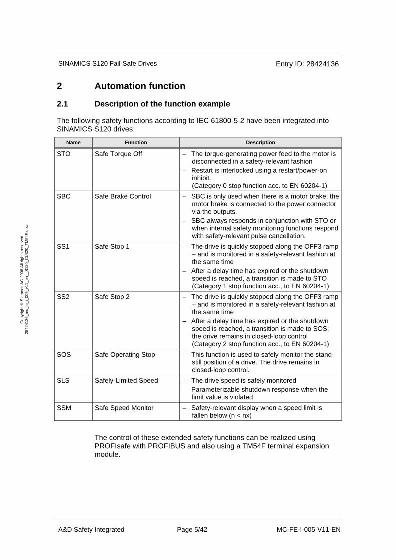
The following safety functions according to IEC 61800-5-2 have been integrated into SINAMICS S120 drives:
Name Function Description
STO Safe Torque Off – The torque-generating power feed to the motor is disconnected in a safety-relevant fashion
– Restart is interlocked using a restart/power-on inhibit. (Category 0 stop function acc. to EN 60204-1)
SBC Safe Brake Control – SBC is only used when there is a motor brake; the motor brake is connected to the power connector via the outputs.
– SBC always responds in conjunction with STO or when internal safety monitoring functions respond with safety-relevant pulse cancellation.
SS1 Safe Stop 1 – The drive is quickly stopped along the OFF3 ramp – and is monitored in a safety-relevant fashion at the same time
– After a delay time has expired or the shutdown speed is reached, a transition is made to STO (Category 1 stop function acc., to EN 60204-1)
SS2 Safe Stop 2 – The drive is quickly stopped along the OFF3 ramp – and is monitored in a safety-relevant fashion at the same time
– After a delay time has expired or the shutdown speed is reached, a transition is made to SOS; the drive remains in closed-loop control (Category 2 stop function acc., to EN 60204-1)
SOS Safe Operating Stop – This function is used to safely monitor the stand-still position of a drive. The drive remains in closed-loop control.
SLS Safely-Limited Speed – The drive speed is safely monitored – Parameterizable shutdown response when the
limit value is violated SSM Safe Speed Monitor – Safety-relevant display when a speed limit is
fallen below (n < nx)
The control of these extended safety functions can be realized using PROFIsafe with PROFIBUS and also using a TM54F terminal expansion module.
SINAMICS S120 Fail-Safe Drives Entry ID: 28424136
A&D Safety Integrated Page 6/42 MC-FE-I-005-V11-EN
Cop
yrig
ht ©
Sie
men
s A
G 2
008
All
right
s re
serv
ed
2842
4136
_mc_
fe_i
_005
_v11
_en_
_S12
0_C
U32
0_TM
54F.
doc
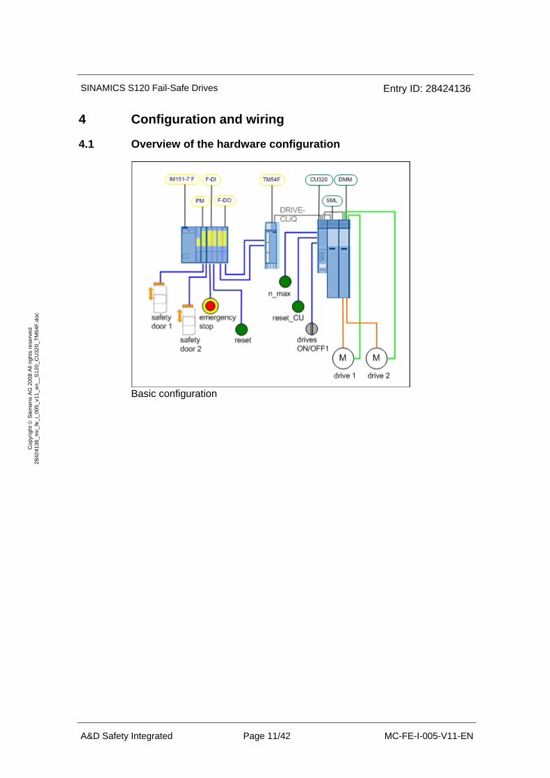
Task description The extended safety functions integrated in the SINAMICS S120 drives are to be controlled from a TM54F via hardware signals. The drives belong to different drive groups. The safety-relevant logical pre-processing of the input signals is handled in an F-CPU.
This application should comply with SIL 2 acc. to EN 62061:2005, ISO 13849-1:2006 PL d or EN 954-1:1996 Category 3.
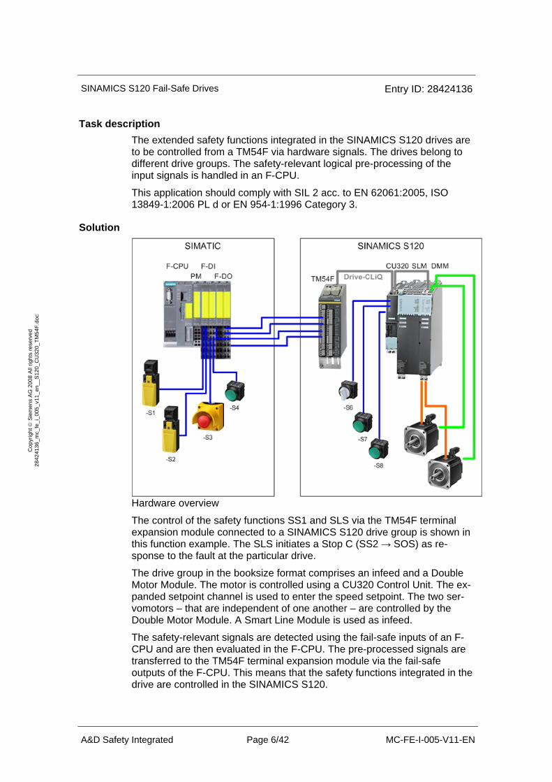
Solution
Hardware overview
The control of the safety functions SS1 and SLS via the TM54F terminal expansion module connected to a SINAMICS S120 drive group is shown in this function example. The SLS initiates a Stop C (SS2 → SOS) as re-sponse to the fault at the particular drive.
The drive group in the booksize format comprises an infeed and a Double Motor Module. The motor is controlled using a CU320 Control Unit. The ex-panded setpoint channel is used to enter the speed setpoint. The two ser-vomotors – that are independent of one another – are controlled by the Double Motor Module. A Smart Line Module is used as infeed.
The safety-relevant signals are detected using the fail-safe inputs of an F-CPU and are then evaluated in the F-CPU. The pre-processed signals are transferred to the TM54F terminal expansion module via the fail-safe outputs of the F-CPU. This means that the safety functions integrated in the drive are controlled in the SINAMICS S120.
SINAMICS S120 Fail-Safe Drives Entry ID: 28424136
A&D Safety Integrated Page 7/42 MC-FE-I-005-V11-EN
Cop
yrig
ht ©
Sie
men
s A
G 2
008
All
right
s re
serv
ed
2842
4136
_mc_
fe_i
_005
_v11
_en_
_S12
0_C
U32
0_TM
54F.
doc
When an Emergency Stop is requested, both of the drives are stopped by the SS1 safety function integrated in the drive. The torque-generating power feed to the motor is interrupted in a safety-relevant fashion using safe pulse cancellation. The restart inhibit is activated.
Each drive is assigned a safety door. If this safety door is opened, then the associated motor is operated at a lower speed and the set speed limit value is safely monitored using the SLS function. The other drive is not influ-enced.
Other ways of using the TM54F terminal expansion module and controlling the safety functions via PROFIsafe are described in additional function ex-amples.
2.2 Advantages / customer benefits
• • The safety functions integrated in the drive are controlled in a simple fashion
• • Simple design/configuring using standardized technology
• • The existing system can be simply and quickly expanded.
• • Space-saving configuration using integrated safety func-tions – additional hardware is not required
Complex safety concepts can be implemented using this as basis.
SINAMICS S120 Fail-Safe Drives Entry ID: 28424136
A&D Safety Integrated Page 8/42 MC-FE-I-005-V11-EN
Cop
yrig
ht ©
Sie
men
s A
G 2
008
All
right
s re
serv
ed
2842
4136
_mc_
fe_i
_005
_v11
_en_
_S12
0_C
U32
0_TM
54F.
doc
3 Components that are required
The hardware components and software versions that are required to im-plement this function example are listed in this Chapter.
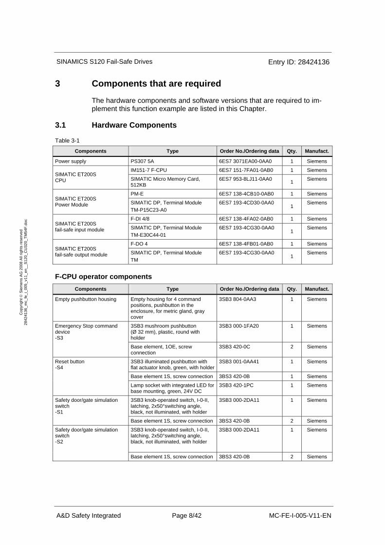
3.1 Hardware Components
Table 3-1
Components Type Order No./Ordering data Qty. Manufact.
Power supply PS307 5A 6ES7 3071EA00-0AA0 1 Siemens
IM151-7 F-CPU 6ES7 151-7FA01-0AB0 1 Siemens SIMATIC ET200S CPU SIMATIC Micro Memory Card,
512KB 6ES7 953-8LJ11-0AA0 1 Siemens
PM-E 6ES7 138-4CB10-0AB0 1 Siemens SIMATIC ET200S Power Module SIMATIC DP, Terminal Module
TM-P15C23-A0 6ES7 193-4CD30-0AA0
1 Siemens
F-DI 4/8 6ES7 138-4FA02-0AB0 1 Siemens SIMATIC ET200S fail-safe input module SIMATIC DP, Terminal Module
TM-E30C44-01 6ES7 193-4CG30-0AA0
1 Siemens
F-DO 4 6ES7 138-4FB01-0AB0 1 Siemens SIMATIC ET200S fail-safe output module SIMATIC DP, Terminal Module
TM 6ES7 193-4CG30-0AA0
1 Siemens
F-CPU operator components Components Type Order No./Ordering data Qty. Manufact.
Empty pushbutton housing Empty housing for 4 command positions, pushbutton in the enclosure, for metric gland, gray cover
3SB3 804-0AA3 1 Siemens
3SB3 mushroom pushbutton (Ø 32 mm), plastic, round with holder
3SB3 000-1FA20 1 Siemens Emergency Stop command device -S3
Base element, 1OE, screw connection
3SB3 420-0C 2 Siemens
3SB3 illuminated pushbutton with flat actuator knob, green, with holder
3SB3 001-0AA41 1 Siemens
Base element 1S, screw connection 3BS3 420-0B 1 Siemens
Reset button -S4
Lamp socket with integrated LED for base mounting, green, 24V DC
3SB3 420-1PC 1 Siemens
3SB3 knob-operated switch, I-0-II, latching, 2x50°switching angle, black, not illuminated, with holder
3SB3 000-2DA11 1 Siemens Safety door/gate simulation switch -S1
Base element 1S, screw connection 3BS3 420-0B 2 Siemens
3SB3 knob-operated switch, I-0-II, latching, 2x50°switching angle, black, not illuminated, with holder
3SB3 000-2DA11 1 Siemens Safety door/gate simulation switch -S2
Base element 1S, screw connection 3BS3 420-0B 2 Siemens
SINAMICS S120 Fail-Safe Drives Entry ID: 28424136
A&D Safety Integrated Page 9/42 MC-FE-I-005-V11-EN
Cop
yrig
ht ©
Sie
men
s A
G 2
008
All
right
s re
serv
ed
2842
4136
_mc_
fe_i
_005
_v11
_en_
_S12
0_C
U32
0_TM
54F.
doc
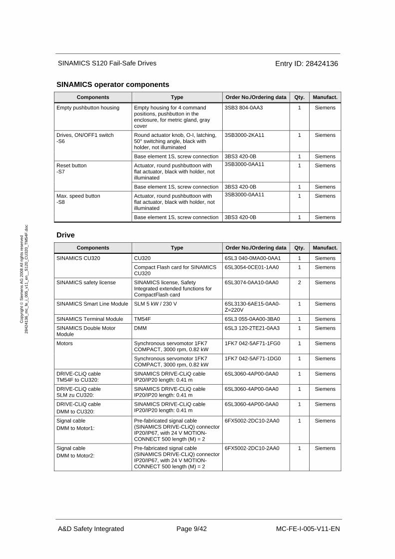
SINAMICS operator components Components Type Order No./Ordering data Qty. Manufact.
Empty pushbutton housing Empty housing for 4 command positions, pushbutton in the enclosure, for metric gland, gray cover
3SB3 804-0AA3 1 Siemens
Round actuator knob, O-I, latching, 50° switching angle, black with holder, not illuminated
3SB3000-2KA11 1 Siemens Drives, ON/OFF1 switch -S6
Base element 1S, screw connection 3BS3 420-0B 1 Siemens
Actuator, round pushbuttoon with flat actuator, black with holder, not illuminated
3SB3000-0AA11 1 Siemens Reset button -S7
Base element 1S, screw connection 3BS3 420-0B 1 Siemens
Actuator, round pushbuttoon with flat actuator, black with holder, not illuminated
3SB3000-0AA11 1 Siemens Max. speed button -S8
Base element 1S, screw connection 3BS3 420-0B 1 Siemens
Drive Components Type Order No./Ordering data Qty. Manufact.
CU320 6SL3 040-0MA00-0AA1 1 Siemens SINAMICS CU320
Compact Flash card for SINAMICS CU320
6SL3054-0CE01-1AA0 1 Siemens
SINAMICS safety license SINAMICS license, Safety Integrated extended functions for CompactFlash card
6SL3074-0AA10-0AA0 2 Siemens
SINAMICS Smart Line Module SLM 5 kW / 230 V 6SL3130-6AE15-0AA0-Z=220V
1 Siemens
SINAMICS Terminal Module TM54F 6SL3 055-0AA00-3BA0 1 Siemens
SINAMICS Double Motor Module
DMM 6SL3 120-2TE21-0AA3 1 Siemens
Synchronous servomotor 1FK7 COMPACT, 3000 rpm, 0.82 kW
1FK7 042-5AF71-1FG0 1 Siemens Motors
Synchronous servomotor 1FK7 COMPACT, 3000 rpm, 0.82 kW
1FK7 042-5AF71-1DG0 1 Siemens
DRIVE-CLiQ cable TM54F to CU320:
SINAMICS DRIVE-CLiQ cable IP20/IP20 length: 0.41 m
6SL3060-4AP00-0AA0 1 Siemens
DRIVE-CLiQ cable SLM zu CU320:
SINAMICS DRIVE-CLiQ cable IP20/IP20 length: 0.41 m
6SL3060-4AP00-0AA0 1 Siemens
DRIVE-CLiQ cable DMM to CU320:
SINAMICS DRIVE-CLiQ cable IP20/IP20 length: 0.41 m
6SL3060-4AP00-0AA0 1 Siemens
Signal cable DMM to Motor1:
Pre-fabricated signal cable (SINAMICS DRIVE-CLiQ) connector IP20/IP67, with 24 V MOTION-CONNECT 500 length (M) = 2
6FX5002-2DC10-2AA0 1 Siemens
Signal cable DMM to Motor2:
Pre-fabricated signal cable (SINAMICS DRIVE-CLiQ) connector IP20/IP67, with 24 V MOTION-CONNECT 500 length (M) = 2
6FX5002-2DC10-2AA0 1 Siemens
SINAMICS S120 Fail-Safe Drives Entry ID: 28424136
A&D Safety Integrated Page 10/42 MC-FE-I-005-V11-EN
Cop
yrig
ht ©
Sie
men
s A
G 2
008
All
right
s re
serv
ed
2842
4136
_mc_
fe_i
_005
_v11
_en_
_S12
0_C
U32
0_TM
54F.
doc
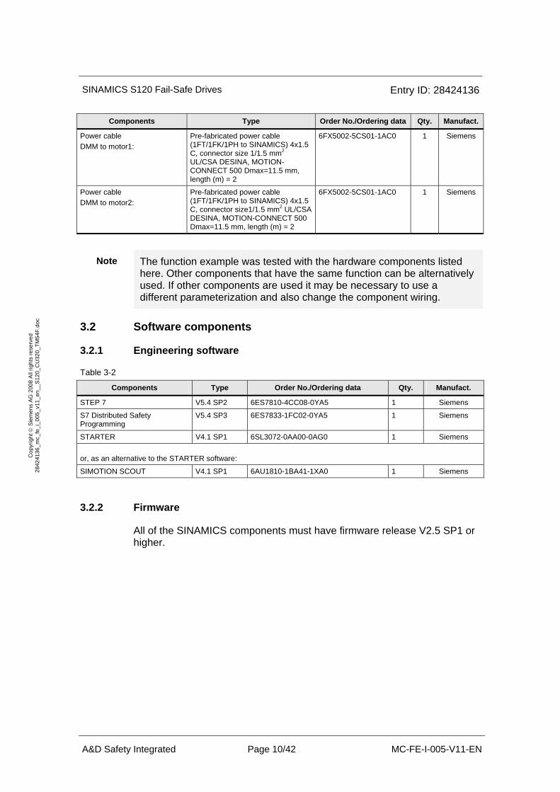
Components Type Order No./Ordering data Qty. Manufact.
Power cable DMM to motor1:
Pre-fabricated power cable (1FT/1FK/1PH to SINAMICS) 4x1.5 C, connector size 1/1.5 mm2 UL/CSA DESINA, MOTION-CONNECT 500 Dmax=11.5 mm, length (m) = 2
6FX5002-5CS01-1AC0 1 Siemens
Power cable DMM to motor2:
Pre-fabricated power cable (1FT/1FK/1PH to SINAMICS) 4x1.5 C, connector size1/1.5 mm2 UL/CSA DESINA, MOTION-CONNECT 500 Dmax=11.5 mm, length (m) = 2
6FX5002-5CS01-1AC0 1 Siemens
Note The function example was tested with the hardware components listed here. Other components that have the same function can be alternatively used. If other components are used it may be necessary to use a different parameterization and also change the component wiring.
3.2 Software components
3.2.1 Engineering software
Table 3-2
Components Type Order No./Ordering data Qty. Manufact.
STEP 7 V5.4 SP2 6ES7810-4CC08-0YA5 1 Siemens
S7 Distributed Safety Programming
V5.4 SP3 6ES7833-1FC02-0YA5 1 Siemens
STARTER V4.1 SP1 6SL3072-0AA00-0AG0 1 Siemens
or, as an alternative to the STARTER software:
SIMOTION SCOUT V4.1 SP1 6AU1810-1BA41-1XA0 1 Siemens
3.2.2 Firmware
All of the SINAMICS components must have firmware release V2.5 SP1 or higher.
SINAMICS S120 Fail-Safe Drives Entry ID: 28424136
A&D Safety Integrated Page 11/42 MC-FE-I-005-V11-EN
Cop
yrig
ht ©
Sie
men
s A
G 2
008
All
right
s re
serv
ed
2842
4136
_mc_
fe_i
_005
_v11
_en_
_S12
0_C
U32
0_TM
54F.
doc
4 Configuration and wiring
4.1 Overview of the hardware configuration
Basic configuration
SINAMICS S120 Fail-Safe Drives Entry ID: 28424136
A&D Safety Integrated Page 12/42 MC-FE-I-005-V11-EN
Cop
yrig
ht ©
Sie
men
s A
G 2
008
All
right
s re
serv
ed
2842
4136
_mc_
fe_i
_005
_v11
_en_
_S12
0_C
U32
0_TM
54F.
doc
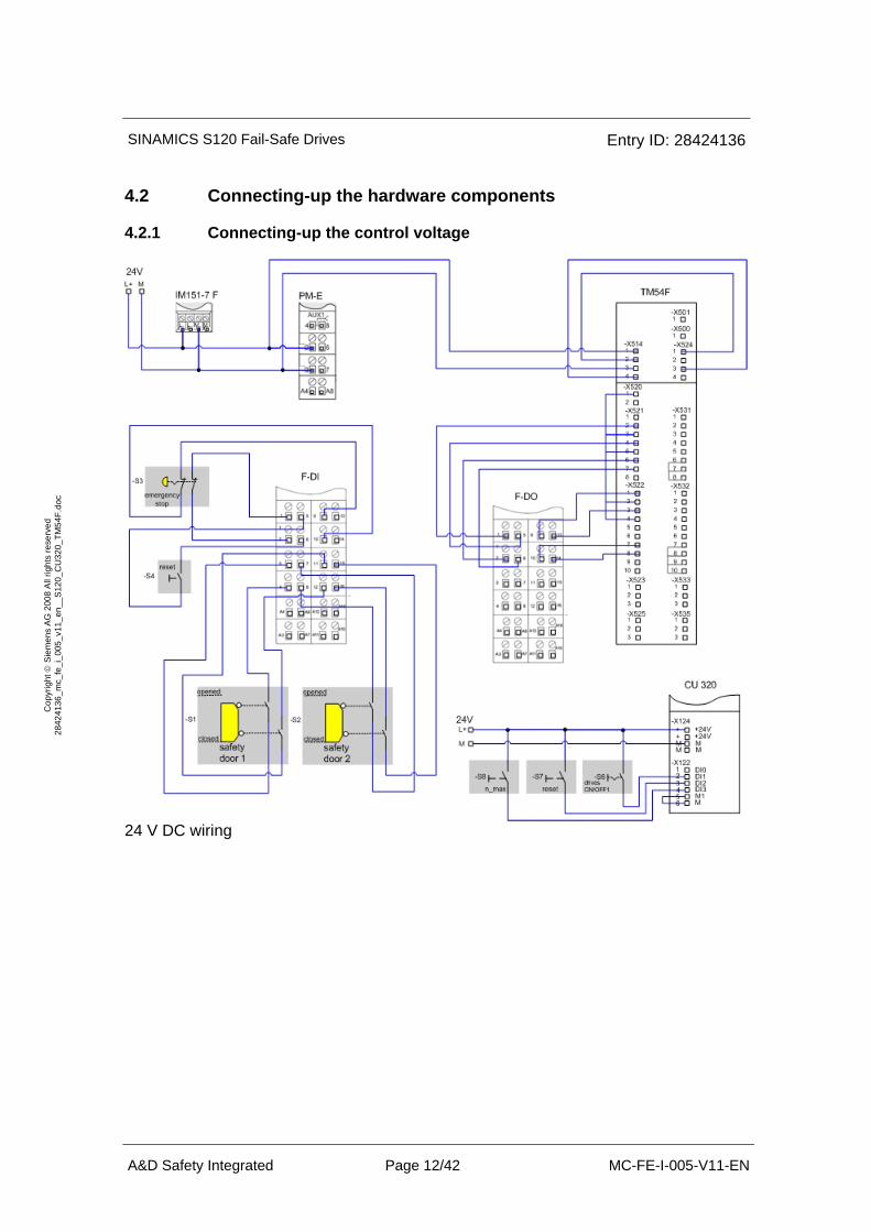
4.2 Connecting-up the hardware components
4.2.1 Connecting-up the control voltage
24 V DC wiring
SINAMICS S120 Fail-Safe Drives Entry ID: 28424136
A&D Safety Integrated Page 13/42 MC-FE-I-005-V11-EN
Cop
yrig
ht ©
Sie
men
s A
G 2
008
All
right
s re
serv
ed
2842
4136
_mc_
fe_i
_005
_v11
_en_
_S12
0_C
U32
0_TM
54F.
doc
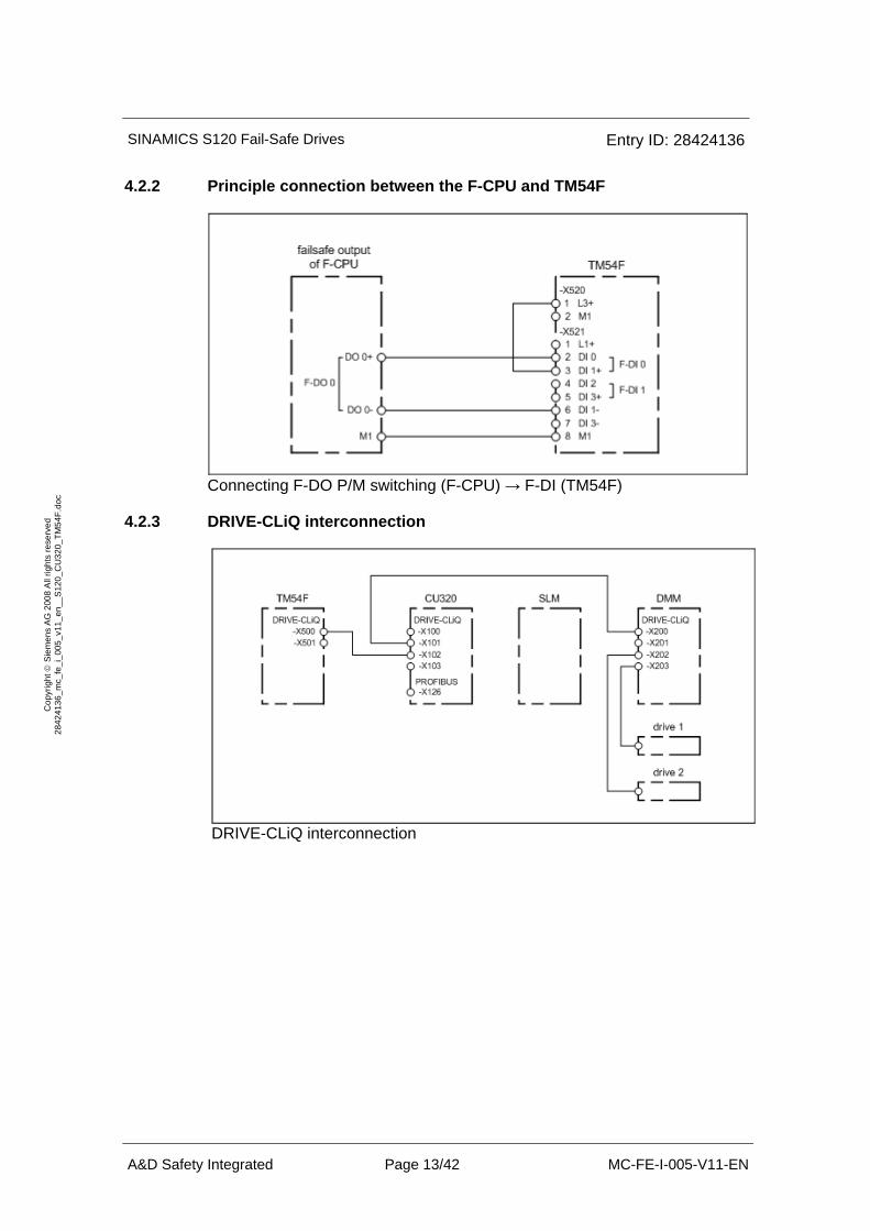
4.2.2 Principle connection between the F-CPU and TM54F
Connecting F-DO P/M switching (F-CPU) → F-DI (TM54F)
4.2.3 DRIVE-CLiQ interconnection
DRIVE-CLiQ interconnection

SINAMICS S120 Fail-Safe Drives Entry ID: 28424136
A&D Safety Integrated Page 14/42 MC-FE-I-005-V11-EN
Cop
yrig
ht ©
Sie
men
s A
G 2
008
All
right
s re
serv
ed
2842
4136
_mc_
fe_i
_005
_v11
_en_
_S12
0_C
U32
0_TM
54F.
doc
4.3 Important settings at the hardware components
In this function example, the PROFIBUS interfaces of the F-CPU and the CU320 are only used for programming. The safety-relevant signal ex-change between the F-CPU and TM54F is only realized through the hard-wired 24V signals.
SINAMICS Control Unit CU320 • • PROFIBUS address = 3
• • The PROFIBUS address is set at the DIL switch below the blind cover of the Control Unit.
SIMATIC IM151-7 F-CPU • • PROFIBUS address = 4
• • When commissioning the system, the programming device must be configured as the only master connected to the bus.
SINAMICS S120 Fail-Safe Drives Entry ID: 28424136
A&D Safety Integrated Page 15/42 MC-FE-I-005-V11-EN
Cop
yrig
ht ©
Sie
men
s A
G 2
008
All
right
s re
serv
ed
2842
4136
_mc_
fe_i
_005
_v11
_en_
_S12
0_C
U32
0_TM
54F.
doc
Prerequisites for operation • • The SIMATIC ET200S components must be mounted and
connected with one another, latched on the mounting rail. The PROFIsafe addresses of the fail-safe input and output modules must be set using the DIL switch; also refer to Chapter 6.2 Hardware configuration of the fail-safe control.
• • All of the components are connected-up as explained in Chapter 4.2 Connecting-up the hardware components.
• • The DRIVE-CLiQ topology of the SINAMICS components is carefully observed.
• • The motors are connected to the Motor Module using the power and encoder cables.
• • The Motor Module is correctly connected to the infeed (DC link and 24 V DC control voltage).
• • The infeed is connected to the line supply.
• • The components are supplied with 24 V DC.
SINAMICS S120 Fail-Safe Drives Entry ID: 28424136
A&D Safety Integrated Page 16/42 MC-FE-I-005-V11-EN
Cop
yrig
ht ©
Sie
men
s A
G 2
008
All
right
s re
serv
ed
2842
4136
_mc_
fe_i
_005
_v11
_en_
_S12
0_C
U32
0_TM
54F.
doc
5 Overview and operator control
5.1 Description of the operator control
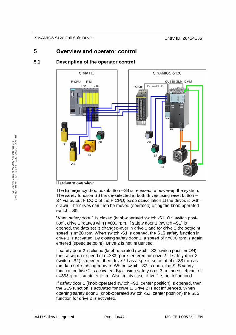
Hardware overview
The Emergency Stop pushbutton –S3 is released to power-up the system. The safety function SS1 is de-selected at both drives using reset button –S4 via output F-DO 0 of the F-CPU; pulse cancellation at the drives is with-drawn. The drives can then be moved (operated) using the knob-operated switch –S6.
When safety door 1 is closed (knob-operated switch -S1, ON switch posi-tion), drive 1 rotates with n=800 rpm. If safety door 1 (switch –S1) is opened, the data set is changed-over in drive 1 and for drive 1 the setpoint speed is n=20 rpm. When switch -S1 is opened, the SLS safety function in drive 1 is activated. By closing safety door 1, a speed of n=800 rpm is again entered (speed setpoint). Drive 2 is not influenced.
If safety door 2 is closed (knob-operated switch –S2, switch position ON) then a setpoint speed of n=333 rpm is entered for drive 2. If safety door 2 (switch –S2) is opened, then drive 2 has a speed setpoint of n=33 rpm as the data set is changed-over. When switch –S2 is open, the SLS safety function in drive 2 is activated. By closing safety door 2, a speed setpoint of n=333 rpm is again entered. Also in this case, drive 1 is not influenced.
If safety door 1 (knob-operated switch –S1, center position) is opened, then the SLS function is activated for drive 1. Drive 2 is not influenced. When opening safety door 2 (knob-operated switch -S2, center position) the SLS function for drive 2 is activated.
SINAMICS S120 Fail-Safe Drives Entry ID: 28424136
A&D Safety Integrated Page 17/42 MC-FE-I-005-V11-EN
Cop
yrig
ht ©
Sie
men
s A
G 2
008
All
right
s re
serv
ed
2842
4136
_mc_
fe_i
_005
_v11
_en_
_S12
0_C
U32
0_TM
54F.
doc
The motors rotate in opposite directions.
When button –S8 is pressed, the drives receive a higher setpoint - inde-pendent of the position of the safety door. For drive 1, n=1000 rpm and for drive 2, n=666 rpm. When the safety door is open, then an SLS limited value is violated and the drive involved is stopped using an internal SS2 (Stop C), and for n=0 rpm is brought into SOS. In order to continue to oper-ate the drive, the alarm, initiated by the internal SS2 (Stop C) as well as the "Internal Event" message signal in the TM54F must be acknowledged using the –S4 reset button.
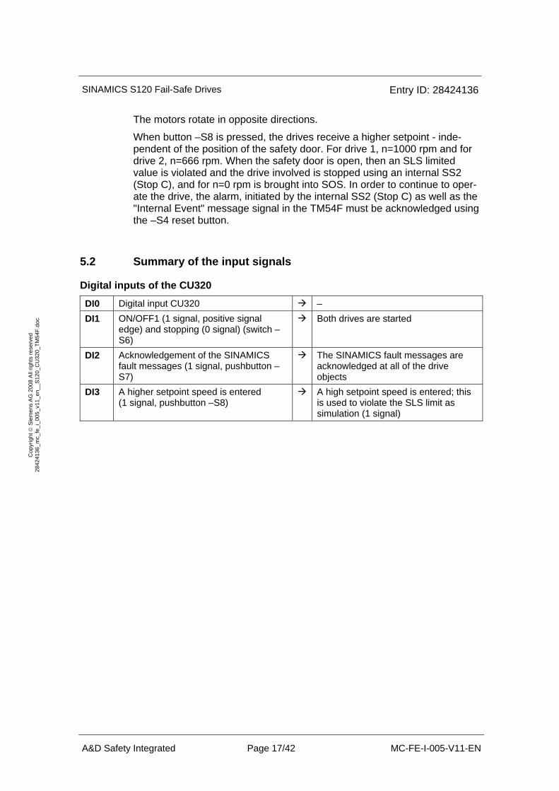
5.2 Summary of the input signals
Digital inputs of the CU320
DI0 Digital input CU320 – DI1 ON/OFF1 (1 signal, positive signal
edge) and stopping (0 signal) (switch –S6)
Both drives are started
DI2 Acknowledgement of the SINAMICS fault messages (1 signal, pushbutton –S7)
The SINAMICS fault messages are acknowledged at all of the drive objects
DI3 A higher setpoint speed is entered (1 signal, pushbutton –S8)
A high setpoint speed is entered; this is used to violate the SLS limit as simulation (1 signal)
SINAMICS S120 Fail-Safe Drives Entry ID: 28424136
A&D Safety Integrated Page 18/42 MC-FE-I-005-V11-EN
Cop
yrig
ht ©
Sie
men
s A
G 2
008
All
right
s re
serv
ed
2842
4136
_mc_
fe_i
_005
_v11
_en_
_S12
0_C
U32
0_TM
54F.
doc
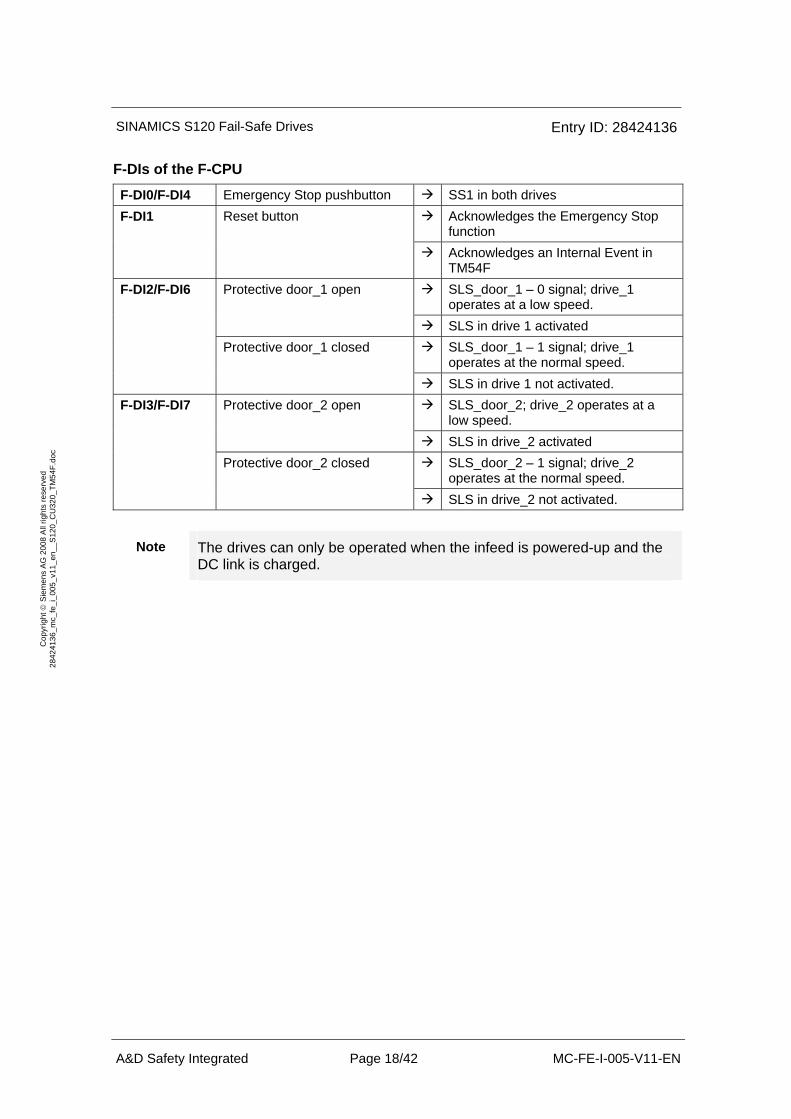
F-DIs of the F-CPU
F-DI0/F-DI4 Emergency Stop pushbutton SS1 in both drives Acknowledges the Emergency Stop function
F-DI1 Reset button
Acknowledges an Internal Event in TM54F SLS_door_1 – 0 signal; drive_1 operates at a low speed.
Protective door_1 open
SLS in drive 1 activated SLS_door_1 – 1 signal; drive_1 operates at the normal speed.
F-DI2/F-DI6
Protective door_1 closed
SLS in drive 1 not activated. SLS_door_2; drive_2 operates at a low speed.
Protective door_2 open
SLS in drive_2 activated SLS_door_2 – 1 signal; drive_2 operates at the normal speed.
F-DI3/F-DI7
Protective door_2 closed
SLS in drive_2 not activated.
Note The drives can only be operated when the infeed is powered-up and the DC link is charged.
SINAMICS S120 Fail-Safe Drives Entry ID: 28424136
A&D Safety Integrated Page 19/42 MC-FE-I-005-V11-EN
Cop
yrig
ht ©
Sie
men
s A
G 2
008
All
right
s re
serv
ed
2842
4136
_mc_
fe_i
_005
_v11
_en_
_S12
0_C
U32
0_TM
54F.
doc
6 Project example
In this chapter, you will learn how the individual components must be pa-rameterized. Both STARTER as well as also SIMOTION SCOUT can be used as engineering software for SINAMICS S120. Distributed Safety is re-quired to program the F-CPU.
A description is subsequently given as to how the software project associ-ated with this function example was set-up.
6.1 Passwords
For reasons of simplicity, in the project, one (1) common safety password is used for the SIMATIC components for both the program and hardware. One (1) password is also used for the safety configuring of the SINAMICS components for the drives and for the TM54F terminal expansion module.
• – Safety password on the F-CPU: "0"
• – Safety password on SINAMICS: "1" These passwords should be changed for real applications!
SINAMICS S120 Fail-Safe Drives Entry ID: 28424136
A&D Safety Integrated Page 20/42 MC-FE-I-005-V11-EN
Cop
yrig
ht ©
Sie
men
s A
G 2
008
All
right
s re
serv
ed
2842
4136
_mc_
fe_i
_005
_v11
_en_
_S12
0_C
U32
0_TM
54F.
doc
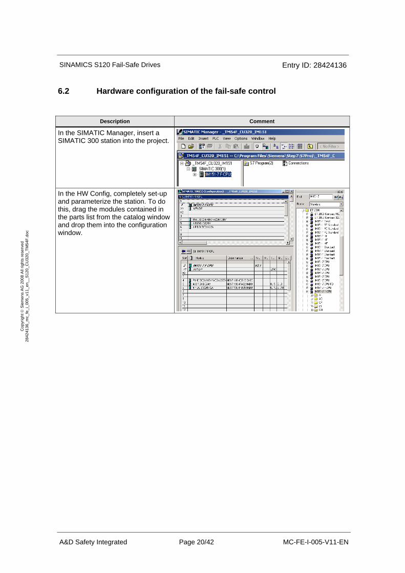
6.2 Hardware configuration of the fail-safe control
Description Comment
In the SIMATIC Manager, insert a SIMATIC 300 station into the project.
In the HW Config, completely set-up and parameterize the station. To do this, drag the modules contained in the parts list from the catalog window and drop them into the configuration window.
SINAMICS S120 Fail-Safe Drives Entry ID: 28424136
A&D Safety Integrated Page 21/42 MC-FE-I-005-V11-EN
Cop
yrig
ht ©
Sie
men
s A
G 2
008
All
right
s re
serv
ed
2842
4136
_mc_
fe_i
_005
_v11
_en_
_S12
0_C
U32
0_TM
54F.
doc
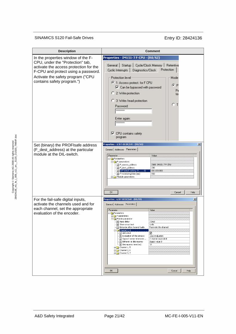
Description Comment
In the properties window of the F-CPU, under the "Protection" tab, activate the access protection for the F-CPU and protect using a password. Activate the safety program ("CPU contains safety program.")
Set (binary) the PROFIsafe address (F_dest_address) at the particular module at the DIL-switch.
For the fail-safe digital inputs, activate the channels used and for each channel, set the appropriate evaluation of the encoder.
SINAMICS S120 Fail-Safe Drives Entry ID: 28424136
A&D Safety Integrated Page 22/42 MC-FE-I-005-V11-EN
Cop
yrig
ht ©
Sie
men
s A
G 2
008
All
right
s re
serv
ed
2842
4136
_mc_
fe_i
_005
_v11
_en_
_S12
0_C
U32
0_TM
54F.
doc
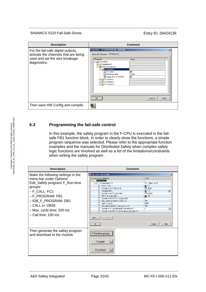
Description Comment
For the fail-safe digital outputs, activate the channels that are being used and set the wire breakage diagnostics.
Then save HW Config and compile.
6.3 Programming the fail-safe control
In this example, the safety program in the F-CPU is executed in the fail-safe FB1 function block. In order to clearly show the functions, a simple program sequence was selected. Please refer to the appropriate function examples and the manuals for Distributed Safety when complex safety logic functions are involved as well as a list of the limitations/constraints when writing the safety program.
Description Comment
Make the following settings in the menu bar under Options/ Edit_Safety program/ F_Run-time groups: – F_CALL: FC1 – F_PROGRAM: FB1 – IDB_F_PROGRAM: DB1 – CALL in: OB35 – Max. cycle time: 200 ms – Call time: 100 ms
Then generate the safety program and download to the module.
SINAMICS S120 Fail-Safe Drives Entry ID: 28424136
A&D Safety Integrated Page 23/42 MC-FE-I-005-V11-EN
Cop
yrig
ht ©
Sie
men
s A
G 2
008
All
right
s re
serv
ed
2842
4136
_mc_
fe_i
_005
_v11
_en_
_S12
0_C
U32
0_TM
54F.
doc
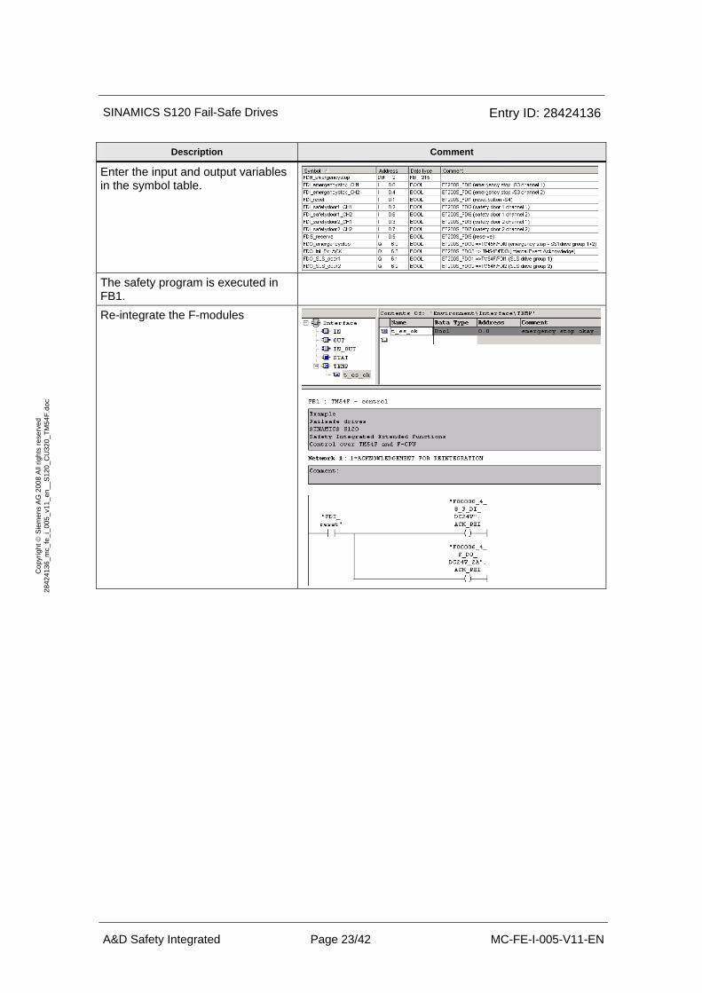
Description Comment
Enter the input and output variables in the symbol table.
The safety program is executed in FB1.
Re-integrate the F-modules

SINAMICS S120 Fail-Safe Drives Entry ID: 28424136
A&D Safety Integrated Page 24/42 MC-FE-I-005-V11-EN
Cop
yrig
ht ©
Sie
men
s A
G 2
008
All
right
s re
serv
ed
2842
4136
_mc_
fe_i
_005
_v11
_en_
_S12
0_C
U32
0_TM
54F.
doc
Description Comment
Emergency Stop analysis and output
SLS_door1 signal at TM54F
SLS_door2 signal at TM54F
SINAMICS S120 Fail-Safe Drives Entry ID: 28424136
A&D Safety Integrated Page 25/42 MC-FE-I-005-V11-EN
Cop
yrig
ht ©
Sie
men
s A
G 2
008
All
right
s re
serv
ed
2842
4136
_mc_
fe_i
_005
_v11
_en_
_S12
0_C
U32
0_TM
54F.
doc
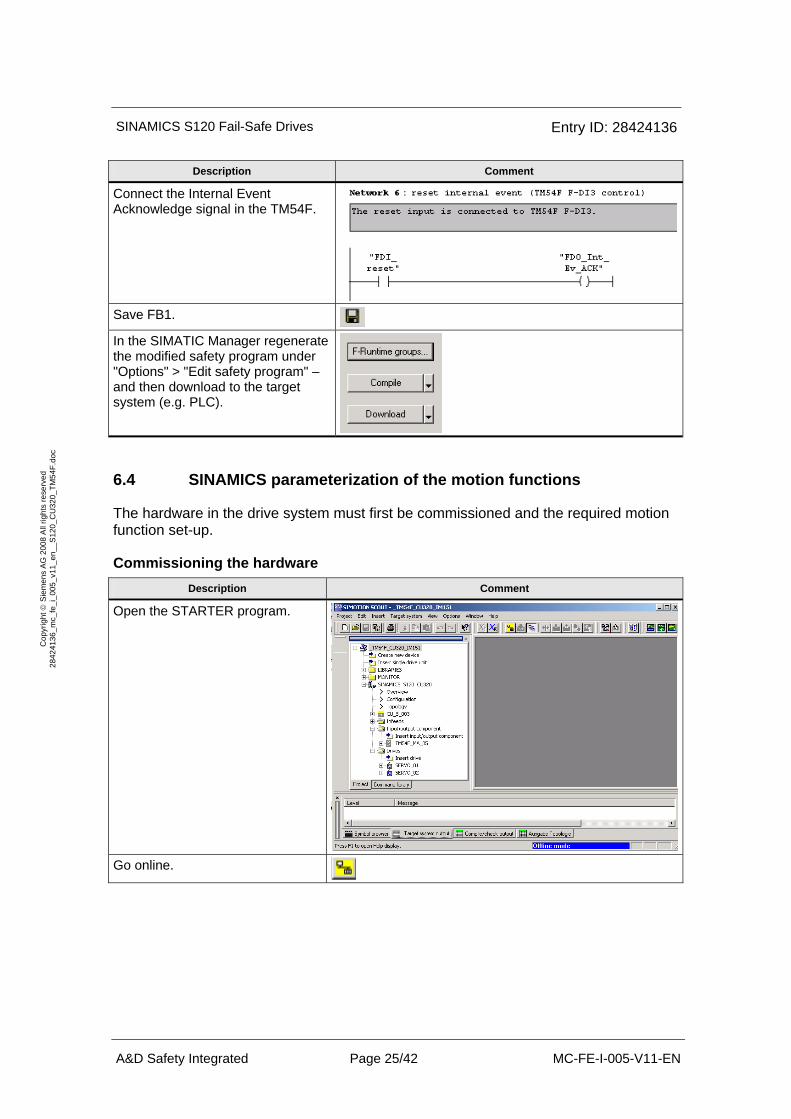
Description Comment
Connect the Internal Event Acknowledge signal in the TM54F.
Save FB1.
In the SIMATIC Manager regenerate the modified safety program under "Options" > "Edit safety program" – and then download to the target system (e.g. PLC).
6.4 SINAMICS parameterization of the motion functions
The hardware in the drive system must first be commissioned and the required motion function set-up.
Commissioning the hardware Description Comment
Open the STARTER program.
Go online.
SINAMICS S120 Fail-Safe Drives Entry ID: 28424136
A&D Safety Integrated Page 26/42 MC-FE-I-005-V11-EN
Cop
yrig
ht ©
Sie
men
s A
G 2
008
All
right
s re
serv
ed
2842
4136
_mc_
fe_i
_005
_v11
_en_
_S12
0_C
U32
0_TM
54F.
doc
Description Comment
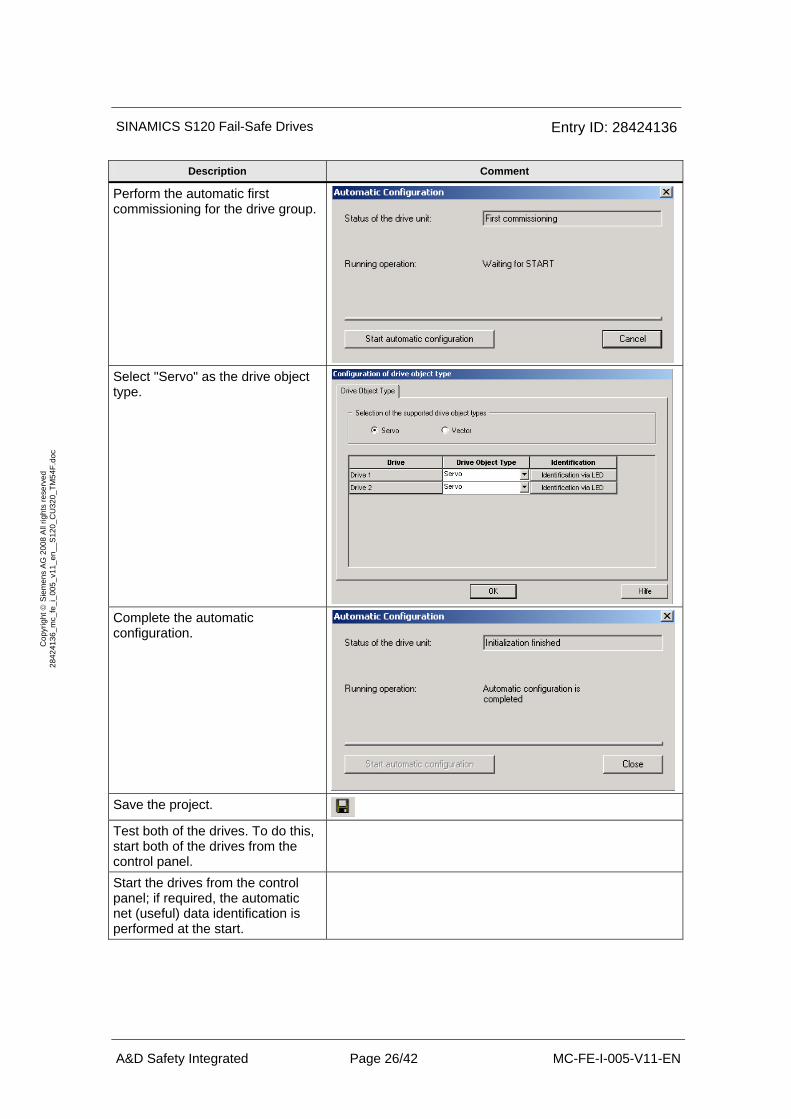
Perform the automatic first commissioning for the drive group.
Select "Servo" as the drive object type.
Complete the automatic configuration.
Save the project.
Test both of the drives. To do this, start both of the drives from the control panel.
Start the drives from the control panel; if required, the automatic net (useful) data identification is performed at the start.
SINAMICS S120 Fail-Safe Drives Entry ID: 28424136
A&D Safety Integrated Page 27/42 MC-FE-I-005-V11-EN
Cop
yrig
ht ©
Sie
men
s A
G 2
008
All
right
s re
serv
ed
2842
4136
_mc_
fe_i
_005
_v11
_en_
_S12
0_C
U32
0_TM
54F.
doc
Description Comment
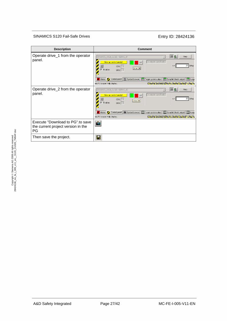
Operate drive_1 from the operator panel.
Operate drive_2 from the operator panel.
Execute "Download to PG".to save the current project version in the PG
Then save the project.
SINAMICS S120 Fail-Safe Drives Entry ID: 28424136
A&D Safety Integrated Page 28/42 MC-FE-I-005-V11-EN
Cop
yrig
ht ©
Sie
men
s A
G 2
008
All
right
s re
serv
ed
2842
4136
_mc_
fe_i
_005
_v11
_en_
_S12
0_C
U32
0_TM
54F.
doc
Commissioning the motion functions (without safety) Description Comment
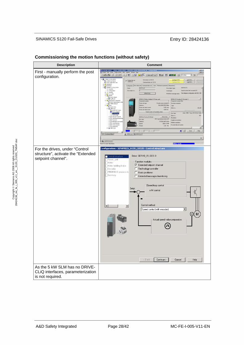
First - manually perform the post configuration.
For the drives, under “Control structure”, activate the "Extended setpoint channel".
As the 5 kW SLM has no DRIVE-CLiQ interfaces, parameterization is not required.
SINAMICS S120 Fail-Safe Drives Entry ID: 28424136
A&D Safety Integrated Page 29/42 MC-FE-I-005-V11-EN
Cop
yrig
ht ©
Sie
men
s A
G 2
008
All
right
s re
serv
ed
2842
4136
_mc_
fe_i
_005
_v11
_en_
_S12
0_C
U32
0_TM
54F.
doc
Description Comment
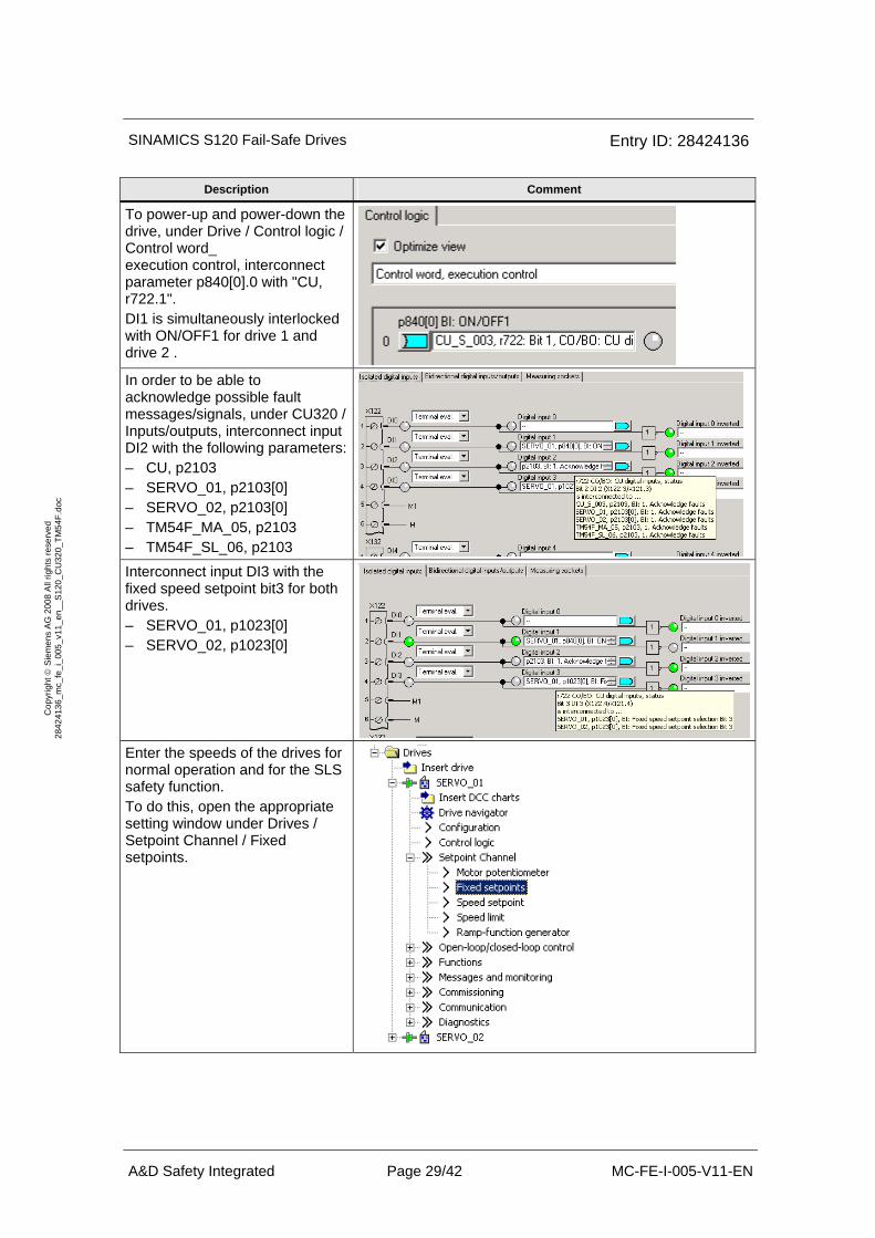
To power-up and power-down the drive, under Drive / Control logic / Control word_ execution control, interconnect parameter p840[0].0 with "CU, r722.1". DI1 is simultaneously interlocked with ON/OFF1 for drive 1 and drive 2 .
In order to be able to acknowledge possible fault messages/signals, under CU320 / Inputs/outputs, interconnect input DI2 with the following parameters: – CU, p2103 – SERVO_01, p2103[0] – SERVO_02, p2103[0] – TM54F_MA_05, p2103 – TM54F_SL_06, p2103
Interconnect input DI3 with the fixed speed setpoint bit3 for both drives. – SERVO_01, p1023[0] – SERVO_02, p1023[0]
Enter the speeds of the drives for normal operation and for the SLS safety function. To do this, open the appropriate setting window under Drives / Setpoint Channel / Fixed setpoints.
SINAMICS S120 Fail-Safe Drives Entry ID: 28424136
A&D Safety Integrated Page 30/42 MC-FE-I-005-V11-EN
Cop
yrig
ht ©
Sie
men
s A
G 2
008
All
right
s re
serv
ed
2842
4136
_mc_
fe_i
_005
_v11
_en_
_S12
0_C
U32
0_TM
54F.
doc
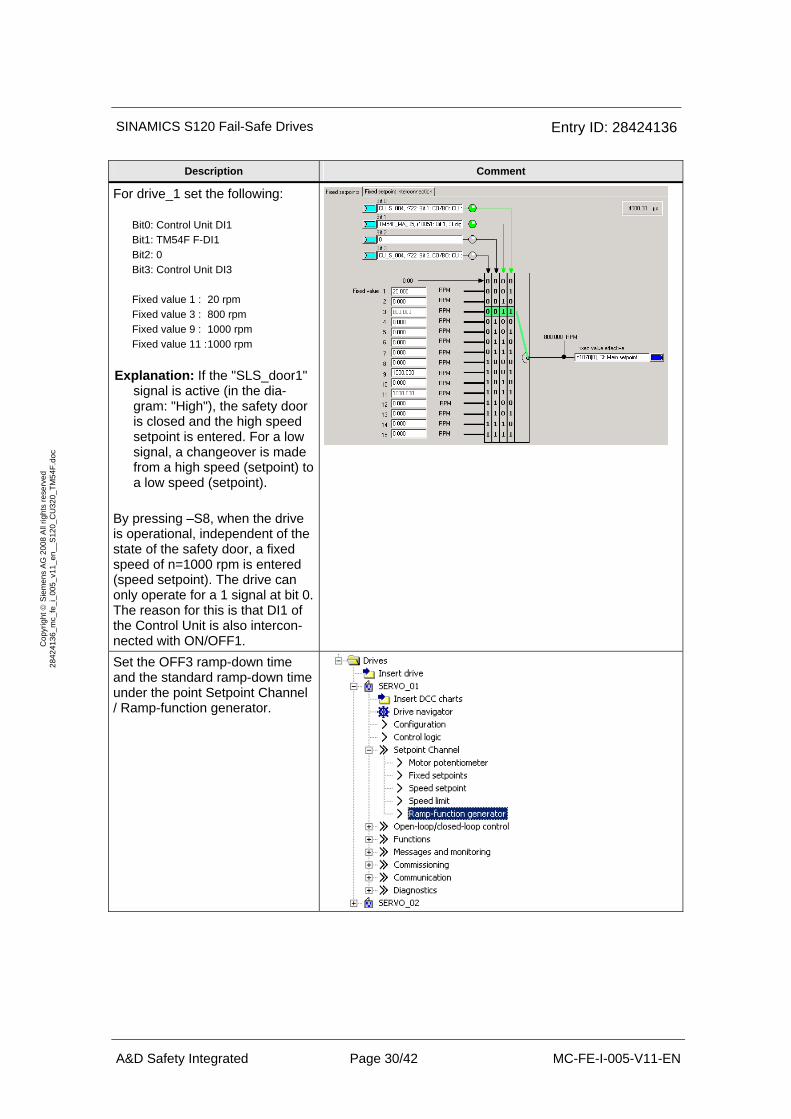
Description Comment
For drive_1 set the following: Bit0: Control Unit DI1 Bit1: TM54F F-DI1 Bit2: 0 Bit3: Control Unit DI3 Fixed value 1 : 20 rpm Fixed value 3 : 800 rpm Fixed value 9 : 1000 rpm Fixed value 11 : 1000 rpm Explanation: If the "SLS_door1"
signal is active (in the dia-gram: "High"), the safety door is closed and the high speed setpoint is entered. For a low signal, a changeover is made from a high speed (setpoint) to a low speed (setpoint).
By pressing –S8, when the drive is operational, independent of the state of the safety door, a fixed speed of n=1000 rpm is entered (speed setpoint). The drive can only operate for a 1 signal at bit 0. The reason for this is that DI1 of the Control Unit is also intercon-nected with ON/OFF1.
Set the OFF3 ramp-down time and the standard ramp-down time under the point Setpoint Channel / Ramp-function generator.
SINAMICS S120 Fail-Safe Drives Entry ID: 28424136
A&D Safety Integrated Page 31/42 MC-FE-I-005-V11-EN
Cop
yrig
ht ©
Sie
men
s A
G 2
008
All
right
s re
serv
ed
2842
4136
_mc_
fe_i
_005
_v11
_en_
_S12
0_C
U32
0_TM
54F.
doc
Description Comment
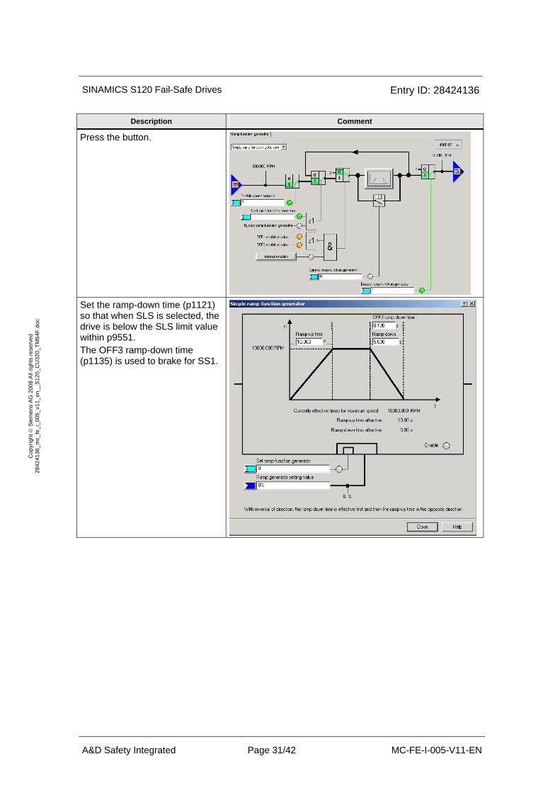
Press the button.
Set the ramp-down time (p1121) so that when SLS is selected, the drive is below the SLS limit value within p9551. The OFF3 ramp-down time (p1135) is used to brake for SS1.
SINAMICS S120 Fail-Safe Drives Entry ID: 28424136
A&D Safety Integrated Page 32/42 MC-FE-I-005-V11-EN
Cop
yrig
ht ©
Sie
men
s A
G 2
008
All
right
s re
serv
ed
2842
4136
_mc_
fe_i
_005
_v11
_en_
_S12
0_C
U32
0_TM
54F.
doc
Description Comment
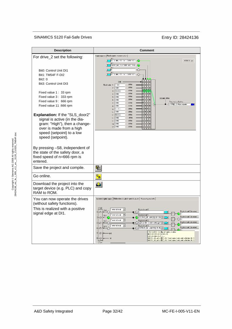
For drive_2 set the following: Bit0: Control Unit DI1 Bit1: TM54F F-DI2 Bit2: 0 Bit3: Control Unit DI3 Fixed value 1 : 33 rpm Fixed value 3 : 333 rpm Fixed value 9 : 666 rpm Fixed value 11 : 666 rpm Explanation: If the "SLS_door2"
signal is active (in the dia-gram: "High"), then a change-over is made from a high speed (setpoint) to a low speed (setpoint).
By pressing –S8, independent of the state of the safety door, a fixed speed of n=666 rpm is entered.
Save the project and compile.
Go online.
Download the project into the target device (e.g. PLC) and copy RAM to ROM.
You can now operate the drives (without safety functions). This is realized with a positive signal edge at DI1.
SINAMICS S120 Fail-Safe Drives Entry ID: 28424136
A&D Safety Integrated Page 33/42 MC-FE-I-005-V11-EN
Cop
yrig
ht ©
Sie
men
s A
G 2
008
All
right
s re
serv
ed
2842
4136
_mc_
fe_i
_005
_v11
_en_
_S12
0_C
U32
0_TM
54F.
doc
6.5 Parameterizing the control of the safety functions (TM54F)
Description Comment
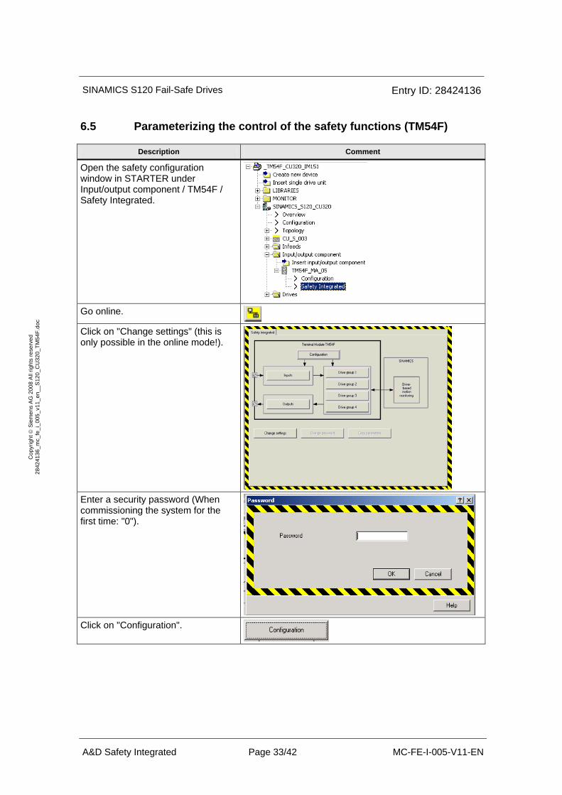
Open the safety configuration window in STARTER under Input/output component / TM54F / Safety Integrated.
Go online.
Click on "Change settings" (this is only possible in the online mode!).
Enter a security password (When commissioning the system for the first time: "0").
Click on "Configuration".
SINAMICS S120 Fail-Safe Drives Entry ID: 28424136
A&D Safety Integrated Page 34/42 MC-FE-I-005-V11-EN
Cop
yrig
ht ©
Sie
men
s A
G 2
008
All
right
s re
serv
ed
2842
4136
_mc_
fe_i
_005
_v11
_en_
_S12
0_C
U32
0_TM
54F.
doc
Description Comment
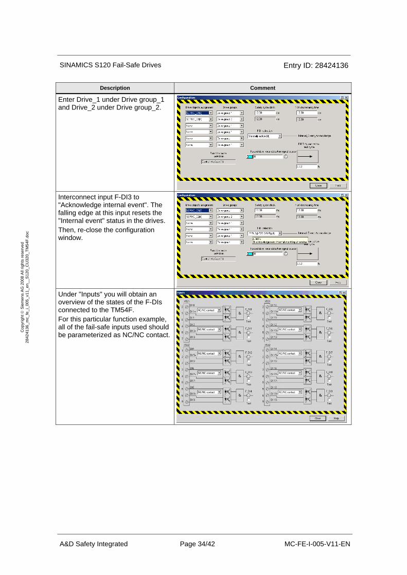
Enter Drive_1 under Drive group_1 and Drive_2 under Drive group_2.
Interconnect input F-DI3 to "Acknowledge internal event". The falling edge at this input resets the "Internal event" status in the drives. Then, re-close the configuration window.
Under "Inputs" you will obtain an overview of the states of the F-DIs connected to the TM54F. For this particular function example, all of the fail-safe inputs used should be parameterized as NC/NC contact.
SINAMICS S120 Fail-Safe Drives Entry ID: 28424136
A&D Safety Integrated Page 35/42 MC-FE-I-005-V11-EN
Cop
yrig
ht ©
Sie
men
s A
G 2
008
All
right
s re
serv
ed
2842
4136
_mc_
fe_i
_005
_v11
_en_
_S12
0_C
U32
0_TM
54F.
doc
Description Comment
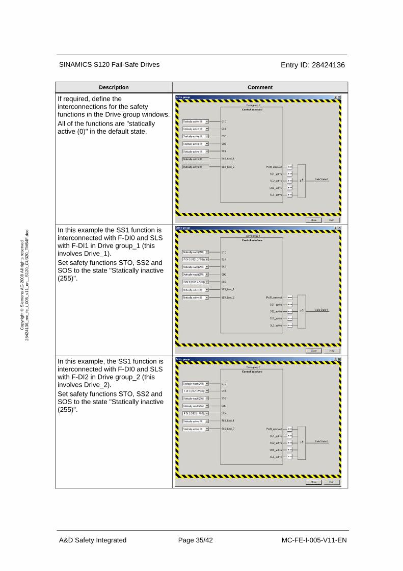
If required, define the interconnections for the safety functions in the Drive group windows.All of the functions are "statically active (0)" in the default state.
In this example the SS1 function is interconnected with F-DI0 and SLS with F-DI1 in Drive group_1 (this involves Drive_1). Set safety functions STO, SS2 and SOS to the state "Statically inactive (255)".
In this example, the SS1 function is interconnected with F-DI0 and SLS with F-DI2 in Drive group_2 (this involves Drive_2). Set safety functions STO, SS2 and SOS to the state "Statically inactive (255)".
SINAMICS S120 Fail-Safe Drives Entry ID: 28424136
A&D Safety Integrated Page 36/42 MC-FE-I-005-V11-EN
Cop
yrig
ht ©
Sie
men
s A
G 2
008
All
right
s re
serv
ed
2842
4136
_mc_
fe_i
_005
_v11
_en_
_S12
0_C
U32
0_TM
54F.
doc
Description Comment
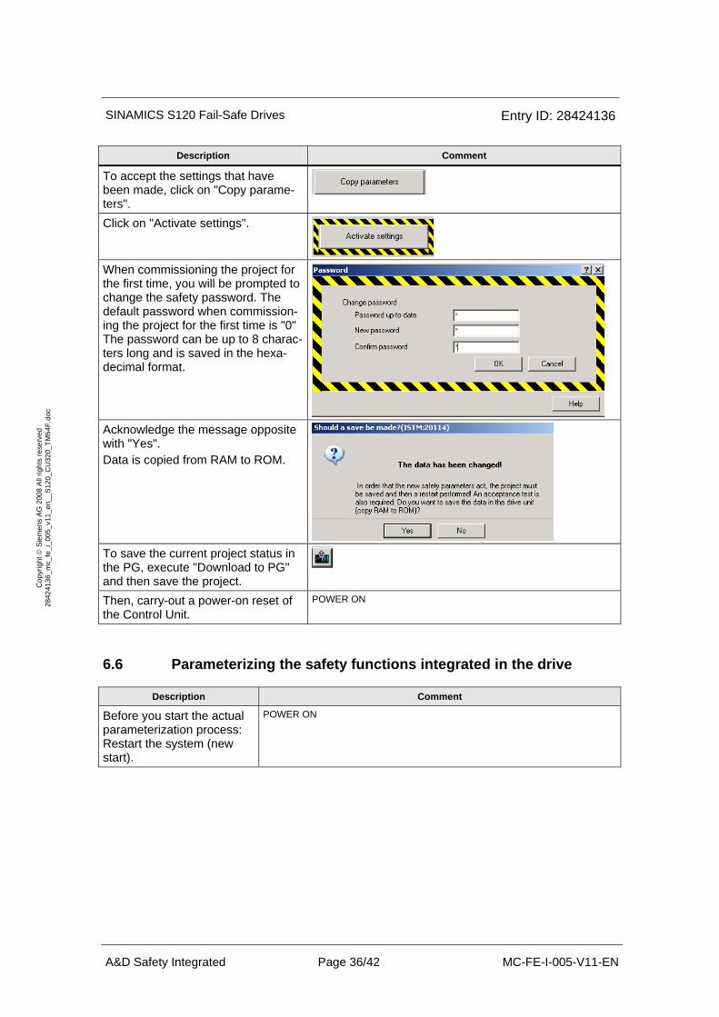
To accept the settings that have been made, click on "Copy parame-ters".
Click on "Activate settings".
When commissioning the project for the first time, you will be prompted to change the safety password. The default password when commission-ing the project for the first time is "0" The password can be up to 8 charac-ters long and is saved in the hexa-decimal format.
Acknowledge the message opposite with "Yes". Data is copied from RAM to ROM.
To save the current project status in the PG, execute "Download to PG" and then save the project.
Then, carry-out a power-on reset of the Control Unit.
POWER ON
6.6 Parameterizing the safety functions integrated in the drive
Description Comment
Before you start the actual parameterization process: Restart the system (new start).
POWER ON
SINAMICS S120 Fail-Safe Drives Entry ID: 28424136
A&D Safety Integrated Page 37/42 MC-FE-I-005-V11-EN
Cop
yrig
ht ©
Sie
men
s A
G 2
008
All
right
s re
serv
ed
2842
4136
_mc_
fe_i
_005
_v11
_en_
_S12
0_C
U32
0_TM
54F.
doc
Description Comment
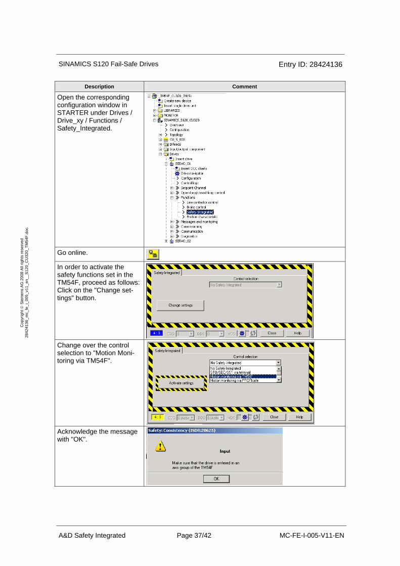
Open the corresponding configuration window in STARTER under Drives / Drive_xy / Functions / Safety_Integrated.
Go online.
In order to activate the safety functions set in the TM54F, proceed as follows: Click on the "Change set-tings" button.
Change over the control selection to "Motion Moni-toring via TM54F".
Acknowledge the message with "OK".
SINAMICS S120 Fail-Safe Drives Entry ID: 28424136
A&D Safety Integrated Page 38/42 MC-FE-I-005-V11-EN
Cop
yrig
ht ©
Sie
men
s A
G 2
008
All
right
s re
serv
ed
2842
4136
_mc_
fe_i
_005
_v11
_en_
_S12
0_C
U32
0_TM
54F.
doc
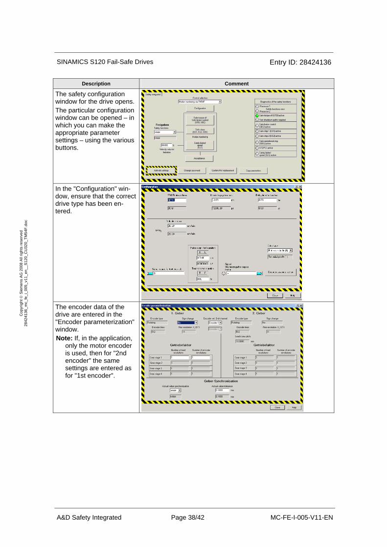
Description Comment
The safety configuration window for the drive opens. The particular configuration window can be opened – in which you can make the appropriate parameter settings – using the various buttons.
In the "Configuration" win-dow, ensure that the correct drive type has been en-tered.
The encoder data of the drive are entered in the "Encoder parameterization" window. Note: If, in the application,
only the motor encoder is used, then for "2nd encoder" the same settings are entered as for "1st encoder".

SINAMICS S120 Fail-Safe Drives Entry ID: 28424136
A&D Safety Integrated Page 39/42 MC-FE-I-005-V11-EN
Cop
yrig
ht ©
Sie
men
s A
G 2
008
All
right
s re
serv
ed
2842
4136
_mc_
fe_i
_005
_v11
_en_
_S12
0_C
U32
0_TM
54F.
doc
Description Comment
Enter the adjacent values in the "Safe stops" screen form. The delay time SS1 -> pulse cancellation (p9556) must be selected so that when the drive decelerates from the maximum speed of the application down to standstill (zero speed), this time is not exceeded. The value of this parameter is, among other things, de-pendent on the load mo-ment of inertia. The shut-down speed SS1 (p9560) is set to n = 0/min.
In the screen form "Safely limited speed (SLS)" - enter the maximum limit speed (limit speed: when the safety door is opened, the speed that is still permissi-ble) Only stage 1 is used for the speed monitoring func-tion. Further, the stop re-sponse – that is initiated when the limit value is ex-ceeded – should be se-lected. The drive speed must be below the limit value n_max. within the delay time "Select SLS -> SLS active" (p9551),
Enable/activate the safety functions.
SINAMICS S120 Fail-Safe Drives Entry ID: 28424136
A&D Safety Integrated Page 40/42 MC-FE-I-005-V11-EN
Cop
yrig
ht ©
Sie
men
s A
G 2
008
All
right
s re
serv
ed
2842
4136
_mc_
fe_i
_005
_v11
_en_
_S12
0_C
U32
0_TM
54F.
doc
Description Comment
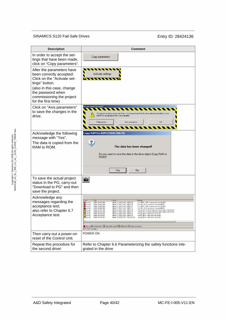
In order to accept the set-tings that have been made, click on “Copy parameters“.
After the parameters have been correctly accepted: Click on the "Activate set-tings" button. (also in this case, change the password when commissioning the project for the first time)
Click on "Axis parameters" to save the changes in the drive.
Acknowledge the following message with "Yes". The data is copied from the RAM to ROM.
To save the actual project status in the PG, carry-out "Download to PG" and then save the project.
Acknowledge any messages regarding the acceptance test; also refer to Chapter 6.7 Acceptance test
Then carry-out a power-on reset of the Control Unit.
POWER ON
Repeat this procedure for the second drive!
Refer to Chapter 6.6 Parameterizing the safety functions inte-grated in the drive
SINAMICS S120 Fail-Safe Drives Entry ID: 28424136
A&D Safety Integrated Page 41/42 MC-FE-I-005-V11-EN
Cop
yrig
ht ©
Sie
men
s A
G 2
008
All
right
s re
serv
ed
2842
4136
_mc_
fe_i
_005
_v11
_en_
_S12
0_C
U32
0_TM
54F.
doc
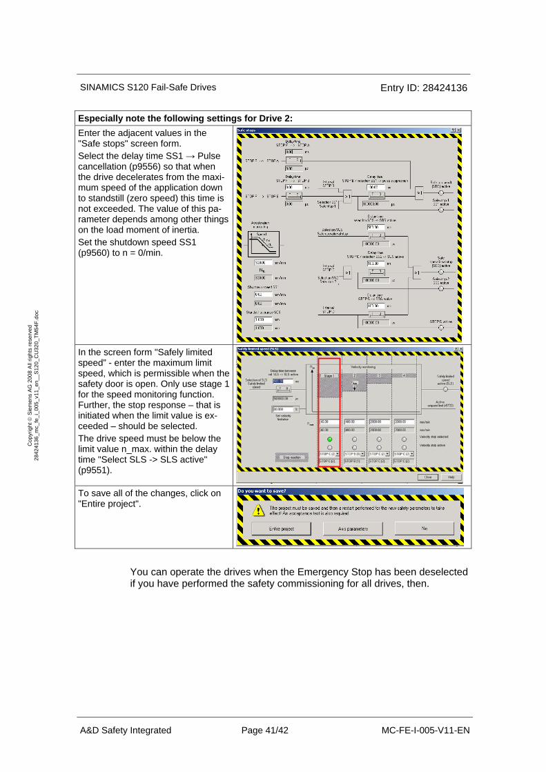
Especially note the following settings for Drive 2: Enter the adjacent values in the "Safe stops" screen form. Select the delay time SS1 → Pulse cancellation (p9556) so that when the drive decelerates from the maxi-mum speed of the application down to standstill (zero speed) this time is not exceeded. The value of this pa-rameter depends among other things on the load moment of inertia. Set the shutdown speed SS1 (p9560) to n = 0/min.
In the screen form "Safely limited speed” - enter the maximum limit speed, which is permissible when the safety door is open. Only use stage 1 for the speed monitoring function. Further, the stop response – that is initiated when the limit value is ex-ceeded – should be selected. The drive speed must be below the limit value n_max. within the delay time "Select SLS -> SLS active" (p9551).
To save all of the changes, click on "Entire project".
You can operate the drives when the Emergency Stop has been deselected if you have performed the safety commissioning for all drives, then.
SINAMICS S120 Fail-Safe Drives Entry ID: 28424136
A&D Safety Integrated Page 42/42 MC-FE-I-005-V11-EN
Cop
yrig
ht ©
Sie
men
s A
G 2
008
All
right
s re
serv
ed
2842
4136
_mc_
fe_i
_005
_v11
_en_
_S12
0_C
U32
0_TM
54F.
doc
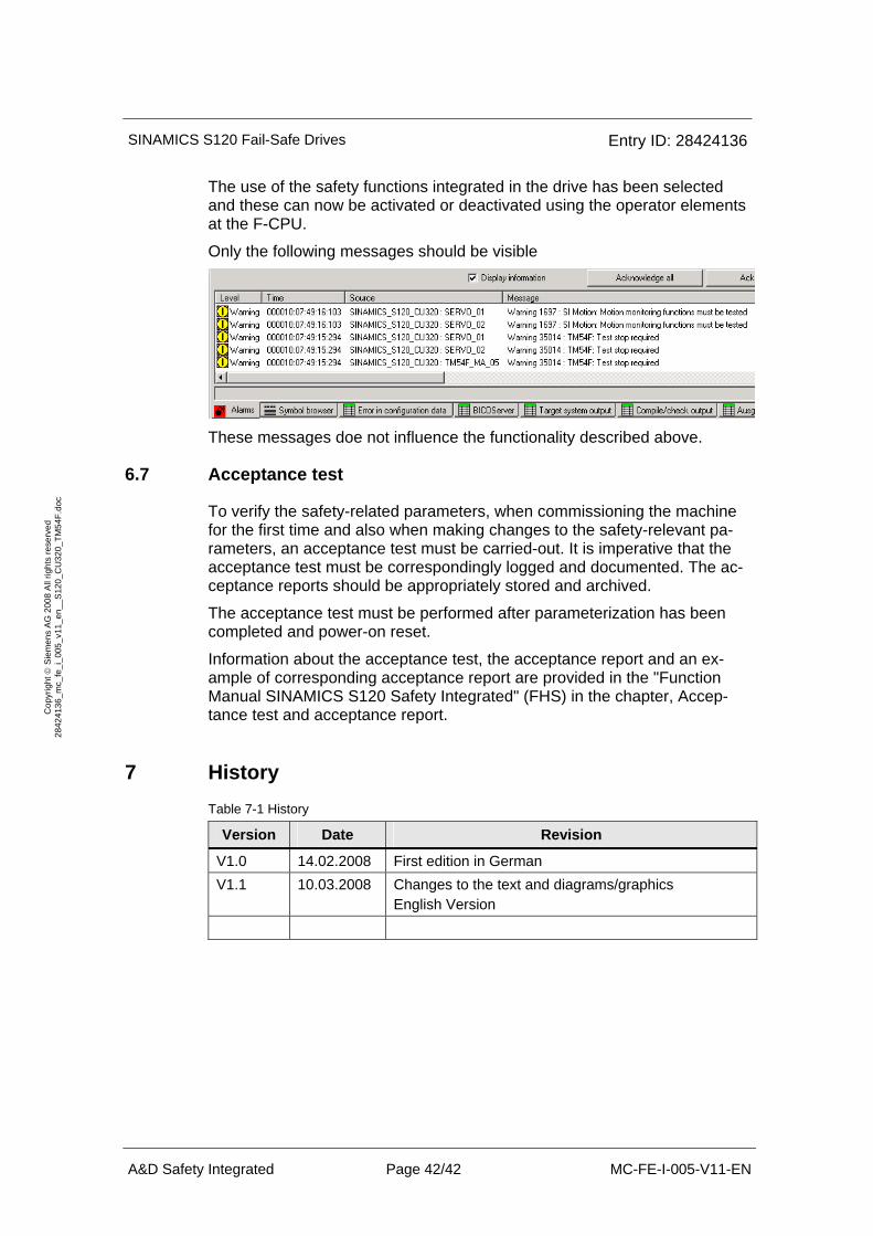
The use of the safety functions integrated in the drive has been selected and these can now be activated or deactivated using the operator elements at the F-CPU.
Only the following messages should be visible
These messages doe not influence the functionality described above.
6.7 Acceptance test
To verify the safety-related parameters, when commissioning the machine for the first time and also when making changes to the safety-relevant pa-rameters, an acceptance test must be carried-out. It is imperative that the acceptance test must be correspondingly logged and documented. The ac-ceptance reports should be appropriately stored and archived.
The acceptance test must be performed after parameterization has been completed and power-on reset.
Information about the acceptance test, the acceptance report and an ex-ample of corresponding acceptance report are provided in the "Function Manual SINAMICS S120 Safety Integrated" (FHS) in the chapter, Accep-tance test and acceptance report.
7 History Table 7-1 History
Version Date Revision
V1.0 14.02.2008 First edition in German V1.1 10.03.2008 Changes to the text and diagrams/graphics
English Version