Embed Size (px)
Citation preview
SINAMICS Drives
SINAMICS S120Motor Modules in booksize format C/D type
siemens.com
Edition November 2015Brochure
© Siemens AG 2016
2
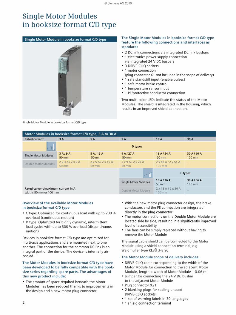
Single Motor Modules in booksize format C/D type
Single Motor Module in booksize format C/D type
Single Motor Module in booksize format C/D type
Motor Modules in booksize format C/D type, 3 A to 30 ARated current 3 A 5 A 9 A 18 A 30 A
D types
Single Motor Modules 3 A / 9 A 50 mm
5 A / 15 A 50 mm
9 A / 27 A 50 mm
18 A / 54 A 50 mm
30 A / 90 A 100 mm
Double Motor Modules 2 x 3 A / 2 x 9 A 50 mm
2 x 5 A / 2 x 15 A 50 mm
2 x 9 A / 2 x 27 A 50 mm
2 x 18 A / 2 x 54 A 100 mm –
Rated current/maximum current in A widths 50 mm or 100 mm
C types
Single Motor Modules 18 A / 36 A 50 mm
30 A / 56 A 100 mm
Double Motor Module 2 x 18 A / 2 x 36 A 100 mm –
Overview of the available Motor Modules in booksize format C/D type• C type: Optimized for continuous load with up to 200 %
overload (continuous motion)• D type: Optimized for highly dynamic, intermittent
load cycles with up to 300 % overload (discontinuous motion)
Devices in booksize format C/D type are optimized for multi-axis applications and are mounted next to one another. The connection for the common DC link is an integral part of the device. The device is internally air cooled.
The Motor Modules in booksize format C/D type have been developed to be fully compatible with the book-size series regarding spare parts. The advantages of this new product include:• The amount of space required beneath the Motor
Modules has been reduced thanks to improvements in the design and a new motor plug connector
• With the new motor plug connector design, the brake conductors and the PE connection are integrated directly in the plug connector
• The motor connections on the Double Motor Module are located side by side, resulting in a significantly improved level of accessibility
• The fans can be simply replaced without having to remove the Motor Module
The signal cable shield can be connected to the Motor Module using a shield connection terminal, e.g. Weidmüller type KLBÜ 3-8 SC.
The Motor Module scope of delivery includes:• DRIVE-CLiQ cable corresponding to the width of the
Motor Module for connection to the adjacent Motor Module, length = width of Motor Module + 0.06 m
• Jumper for connecting the 24 V DC busbar to the adjacent Motor Module
• Plug connector X21• 2 blanking plugs for sealing unused
DRIVE-CLiQ sockets• 1 set of warning labels in 30 languages• 1 shield connection terminal
The Single Motor Modules in booksize format C/D type feature the following connections and interfaces as standard:• 2 DC link connections via integrated DC link busbars• 1 electronics power supply connection
via integrated 24 V DC busbars• 3 DRIVE-CLiQ sockets• 1 motor connection
(plug connector X1 not included in the scope of delivery)• 1 safe standstill input (enable pulses)• 1 safe motor brake control• 1 temperature sensor input• 1 PE/protective conductor connection
Two multi-color LEDs indicate the status of the Motor Modules. The shield is integrated in the housing, which results in an improved shield connection.
© Siemens AG 2016

3
Integration
Single Motor Modules communicate with the Control Unit via DRIVE-CLiQ.
Connection example of Single Motor Modules in booksize format C/D type, 3 A to 30 A
Single Motor Modules in booksize format C/D type
24 V DC busbars
1) Required for safety. 2) Temperature sensor connection for motors without DRIVE-CLiQ interface.3) The brake control has integrated surge voltage protection.
It is not necessary to connect external RC components to the holding brake.
DC link busbars
DRIV
E-CL
iQ so
cket
0
DRIV
E-CL
iQ so
cket
1
DRIVE-CLiQ socket 2
READY
LEDs
+ Temp
- Temp
EP M1
EP +24 V
DC LINK
Single Motor Module
G_D212_EN_00081
© Siemens AG 2016
4
Single Motor Module in booksize format C/D type
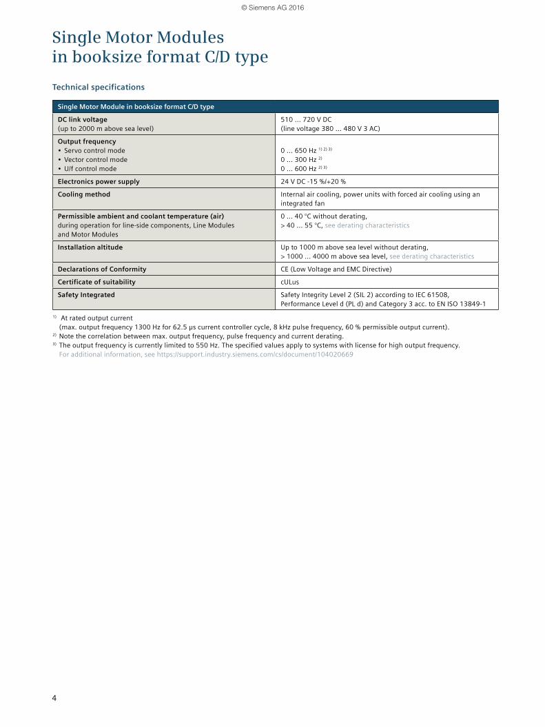
DC link voltage (up to 2000 m above sea level)
510 ... 720 V DC (line voltage 380 ... 480 V 3 AC)
Output frequency • Servo control mode• Vector control mode• U/f control mode
0 ... 650 Hz 1) 2) 3)
0 ... 300 Hz 2)
0 ... 600 Hz 2) 3)
Electronics power supply 24 V DC -15 %/+20 %
Cooling method Internal air cooling, power units with forced air cooling using an integrated fan
Permissible ambient and coolant temperature (air)during operation for line-side components, Line Modules and Motor Modules
0 ... 40 °C without derating, > 40 ... 55 °C, see derating characteristics
Installation altitude Up to 1000 m above sea level without derating, > 1000 ... 4000 m above sea level, see derating characteristics
Declarations of Conformity CE (Low Voltage and EMC Directive)
Certificate of suitability cULus
Safety Integrated Safety Integrity Level 2 (SIL 2) according to IEC 61508, Performance Level d (PL d) and Category 3 acc. to EN ISO 13849-1
1) At rated output current (max. output frequency 1300 Hz for 62.5 µs current controller cycle, 8 kHz pulse frequency, 60 % permissible output current).
2) Note the correlation between max. output frequency, pulse frequency and current derating.3) The output frequency is currently limited to 550 Hz. The specified values apply to systems with license for high output frequency.
For additional information, see https://support.industry.siemens.com/cs/document/104020669
Technical specifications
Single Motor Modules in booksize format C/D type
© Siemens AG 2016

5
DC link voltage 510 ... 720 V DC
Single Motor Module in booksize format C/D type
Internal air cooling C type 6SL3120-... – – – 1TE21-8AC0 1TE23-0AC0
Internal air cooling D type 6SL3120-... 1TE13-0AD0 1TE15-0AD0 1TE21-0AD0 1TE21-8AD0 1TE23-0AD0
Output current• Rated current Irated• Base-load current IH• For S6 duty (40 %) IS6
– C type – D type
• Imax – C type – D type
A A A A A A
3 2.6 – 4 – 9
5 4.3 – 6.7 – 15
9 7.7 13 – 27
18 15.3 24 24 36 54
30 25.5 40 40 56 90
Type rating 1)
• Based on Irated• Based on IH
kW kW
1.6 1.4
2.7 2.3
4.8 4.1
9.7 8.2
16 13.7
Rated pulse frequency kHz 4 4 4 4 4
DC link current Id 2) A 3.6 6 11 22 36
Current carrying capacity• DC link busbars• 24 V DC busbars 4)
A A
100 3) 20
100 3) 20
100 3) 20
100 3) 20
100 3) 20
DC link capacitance μF 110 110 110 220 705
Current demandAt 24 V DC, max.
A 0.75 0.75 0.75 0.75 0.8
Internal air cooling• Power loss 5)
– Maximum losses – Typical losses 6)
• Cooling air requirement• Sound press. level LpA (1 m)
kW kW m3/s dB
0.05 0.03 0.009 <60
0.07 0.04 0.009 <60
0.1 0.06 0.009 <60
0.19 0.14 0.009 <60
0.31 0.26 0.0155 <60
Motor connectionU2, V2, W2
Plug connector (X1) 7) 1.5 ... 6 mm2
Plug connector (X1) 7) 1.5 ... 6 mm2
Plug connector (X1) 7) 1.5 ... 6 mm2
Plug connector (X1) 7) 1.5 ... 6 mm2
Plug connector (X1) 7) 1.5 ... 6 mm2
PE connection M5 screw M5 screw M5 screw M5 screw M5 screw
Motor brake connection Integrated in the motor plug connector (X1), 24 V DC, 2 A
Integrated in the motor plug connector (X1), 24 V DC, 2 A
Integrated in the motor plug connector (X1), 24 V DC, 2 A
Integrated in the motor plug connector (X1), 24 V DC, 2 A
Integrated in the motor plug connector (X1), 24 V DC, 2 A
Motor cable length, max.• Shielded • Unshielded
m m
50 75
50 75
50 75
70 100
100 150
Degree of protection IP20 IP20 IP20 IP20 IP20
Dimensions• Width• Height• Depth
mm mm mm
50 380 270
50 380 270
50 380 270
50 380 270
100 380 270
Weight, approx. kg 4.6 4.6 4.6 4.6 7.91) Rated power of a typical standard induction motor at 400 V 3 AC.2) Rated DC link current for dimensioning an external DC connection.3) With reinforced DC link busbar set, 150 A is possible (accessories).4) If the current carrying capacity exceeds 20 A as several Line Modules and Motor Modules are mounted side-by-side, an additional 24 V DC
connection using a 24 V terminal adapter is required (max. cross-section 6 mm2, max. fuse protection 20 A).5) Power loss of Motor Module at rated power including losses of 24 V DC electronics power supply.6) At the max. motor cable length 30 m, pulse frequency 4 kHz and DC link voltage 540 ... 600 V.7) Plug connector not included in scope of delivery, see Accessories.
Technical specifications
Single Motor Modules in booksize format C/D type
© Siemens AG 2016
6
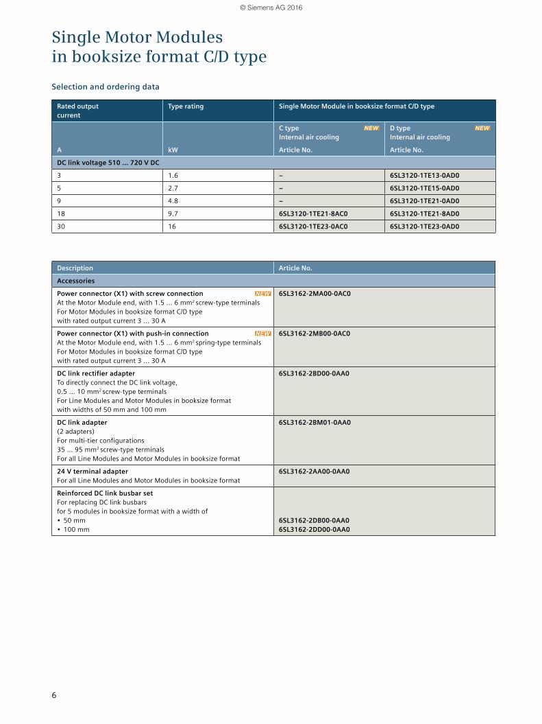
Rated output current
Type rating Single Motor Module in booksize format C/D type
C type Internal air cooling
D type Internal air cooling
A kW Article No. Article No.
DC link voltage 510 ... 720 V DC
3 1.6 – 6SL3120-1TE13-0AD0
5 2.7 – 6SL3120-1TE15-0AD0
9 4.8 – 6SL3120-1TE21-0AD0
18 9.7 6SL3120-1TE21-8AC0 6SL3120-1TE21-8AD0
30 16 6SL3120-1TE23-0AC0 6SL3120-1TE23-0AD0
Description Article No.
Accessories
Power connector (X1) with screw connection At the Motor Module end, with 1.5 ... 6 mm2 screw-type terminals For Motor Modules in booksize format C/D type with rated output current 3 ... 30 A
6SL3162-2MA00-0AC0
Power connector (X1) with push-in connection At the Motor Module end, with 1.5 ... 6 mm2 spring-type terminals For Motor Modules in booksize format C/D type with rated output current 3 ... 30 A
6SL3162-2MB00-0AC0
DC link rectifier adapterTo directly connect the DC link voltage, 0.5 ... 10 mm2 screw-type terminals For Line Modules and Motor Modules in booksize format with widths of 50 mm and 100 mm
6SL3162-2BD00-0AA0
DC link adapter(2 adapters) For multi-tier configurations 35 … 95 mm2 screw-type terminals For all Line Modules and Motor Modules in booksize format
6SL3162-2BM01-0AA0
24 V terminal adapterFor all Line Modules and Motor Modules in booksize format
6SL3162-2AA00-0AA0
Reinforced DC link busbar setFor replacing DC link busbars for 5 modules in booksize format with a width of• 50 mm• 100 mm
6SL3162-2DB00-0AA0 6SL3162-2DD00-0AA0
Selection and ordering data
Single Motor Modules in booksize format C/D type
© Siemens AG 2016

7
Double Motor Module in booksize format C/D type
Double Motor Module in booksize format C/D type
The Double Motor Modules in booksize format C/D type feature the following connections and interfaces as standard:• 2 DC link connections
via integrated DC link busbars• 2 electronics power supply connections
via integrated 24 V DC busbars• 4 DRIVE-CLiQ sockets• 2 motor connections via plug connector
(not included in the scope of delivery)• 2 safe standstill inputs (1 input per axis)• 2 safe motor brake controls• 2 temperature sensor inputs• 1 PE/protective conductor connection
Two multi-color LEDs indicate the status of the Motor Modules. The shield is integrated in the housing, which results in an improved shield connection.
Overview of the available Motor Modules in booksize format C/D type• C type: Optimized for continuous load with up to 200 %
overload (continuous motion)• D type: Optimized for highly dynamic, intermittent load
cycles with up to 300 % overload (discontinuous motion)
Devices in booksize format C/D type are optimized for multi-axis applications and are mounted next to one another. The connection for the common DC link is an integral part of the device. The device is internally air cooled.
The Motor Modules in booksize format C/D type have been developed to be fully compatible with the book-size series regarding spare parts. The advantages of this new product include:• The amount of space required beneath the Motor
Modules has been reduced thanks to improvements in the design and a new motor plug connector
• With the new motor plug connector design, the brake conductors and the PE connection are integrated directly in the plug connector
• The motor connections on the Double Motor Module are located side by side, resulting in a significantly improved level of accessibility
• The fans can be simply replaced without having to remove the Motor Module
The signal cable shield can be connected to the Motor Module using a shield connection terminal, e.g. Weidmüller type KLBÜ 3-8 SC.
The Motor Module scope of delivery includes:• DRIVE-CLiQ cable corresponding to the width of the
Motor Module for connection to the adjacent Motor Module, length = width of Motor Module + 0.06 m
• 2 blanking plugs for sealing unused DRIVE-CLiQ sockets
• Jumper for connecting the 24 V DC busbar to the adjacent Motor Module
• Plug connectors X21 and X22• Device fans for cooling the power units, which are
operated from the internal voltage levels• 1 set of warning labels in 30 languages• 1 shield connection terminal
Motor Modules in booksize format C/D type, 2 x 3 A to 2 x 18 ARated current 3 A 5 A 9 A 18 A 30 A
D types
Single Motor Modules 3 A / 9 A 50 mm
5 A / 15 A 50 mm
9 A / 27 A 50 mm
18 A / 54 A 50 mm
30 A / 90 A 100 mm
Double Motor Modules 2 x 3 A / 2 x 9 A 50 mm
2 x 5 A / 2 x 15 A 50 mm
2 x 9 A / 2 x 27 A 50 mm
2 x 18 A / 2 x 54 A 100 mm –
Rated current/maximum current in A widths 50 mm or 100 mm
C types
Single Motor Modules 18 A / 36 A 50 mm
30 A / 56 A 100 mm
Double Motor Module 2 x 18 A / 2 x 36 A 100 mm –
Double Motor Modules in booksize format C/D type
© Siemens AG 2016
8
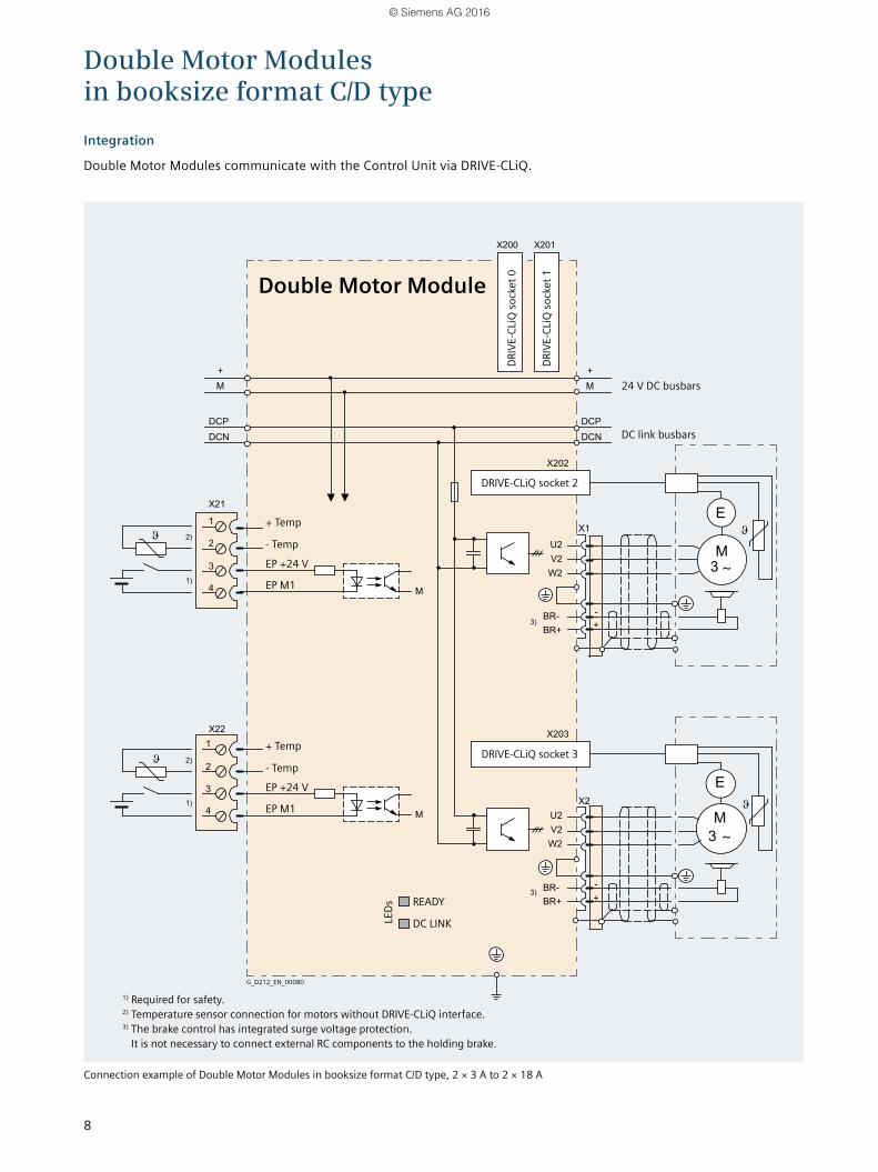
Integration
Double Motor Modules communicate with the Control Unit via DRIVE-CLiQ.
Connection example of Double Motor Modules in booksize format C/D type, 2 × 3 A to 2 × 18 A
Double Motor Modules in booksize format C/D type
24 V DC busbars
1) Required for safety. 2) Temperature sensor connection for motors without DRIVE-CLiQ interface.3) The brake control has integrated surge voltage protection.
It is not necessary to connect external RC components to the holding brake.
DC link busbars
DRIV
E-CL
iQ so
cket
0
DRIV
E-CL
iQ so
cket
1
DRIVE-CLiQ socket 2
DRIVE-CLiQ socket 3
READY
LEDs
+ Temp
+ Temp
- Temp
- Temp
EP M1
EP M1
EP +24 V
EP +24 V
DC LINK
Double Motor Module
G_D212_EN_00080
© Siemens AG 2016
9
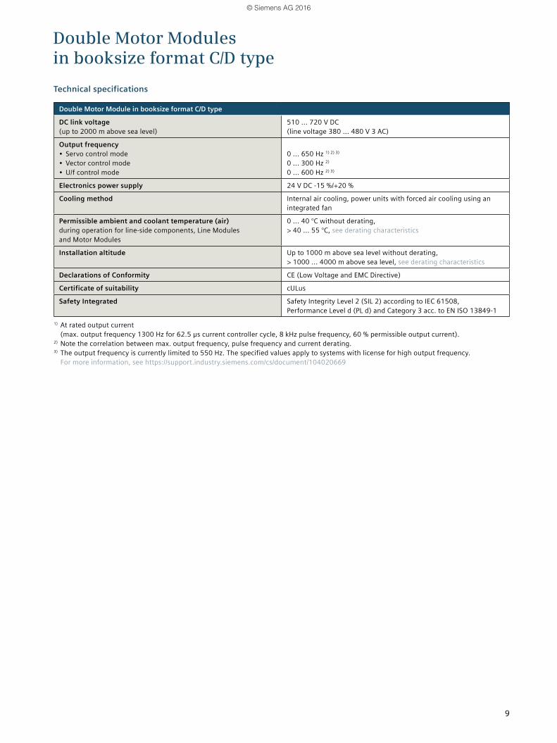
Double Motor Module in booksize format C/D type
DC link voltage (up to 2000 m above sea level)
510 ... 720 V DC (line voltage 380 ... 480 V 3 AC)
Output frequency• Servo control mode• Vector control mode• U/f control mode
0 ... 650 Hz 1) 2) 3) 0 ... 300 Hz 2) 0 ... 600 Hz 2) 3)
Electronics power supply 24 V DC -15 %/+20 %
Cooling method Internal air cooling, power units with forced air cooling using an integrated fan
Permissible ambient and coolant temperature (air)during operation for line-side components, Line Modules and Motor Modules
0 ... 40 °C without derating, > 40 ... 55 °C, see derating characteristics
Installation altitude Up to 1000 m above sea level without derating, > 1000 ... 4000 m above sea level, see derating characteristics
Declarations of Conformity CE (Low Voltage and EMC Directive)
Certificate of suitability cULus
Safety Integrated Safety Integrity Level 2 (SIL 2) according to IEC 61508, Performance Level d (PL d) and Category 3 acc. to EN ISO 13849-1
1) At rated output current (max. output frequency 1300 Hz for 62.5 µs current controller cycle, 8 kHz pulse frequency, 60 % permissible output current).
2) Note the correlation between max. output frequency, pulse frequency and current derating.3) The output frequency is currently limited to 550 Hz. The specified values apply to systems with license for high output frequency.
For more information, see https://support.industry.siemens.com/cs/document/104020669
Technical specifications
Double Motor Modules in booksize format C/D type
© Siemens AG 2016
10
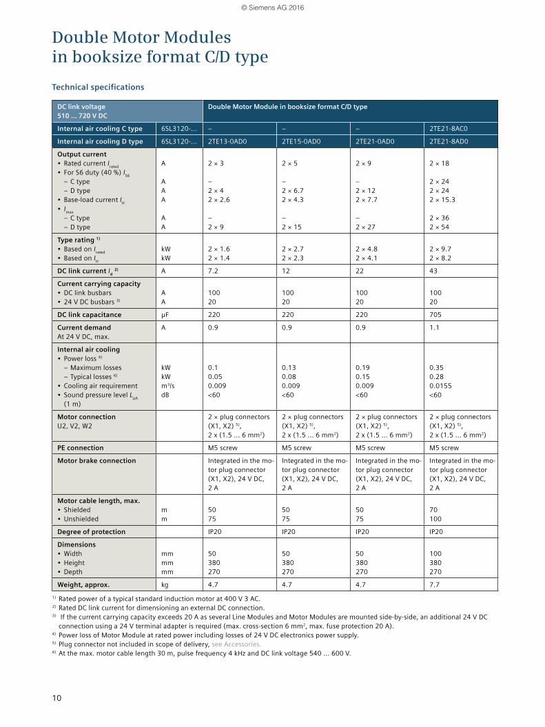
DC link voltage 510 ... 720 V DC
Double Motor Module in booksize format C/D type
Internal air cooling C type 6SL3120-... – – – 2TE21-8AC0
Internal air cooling D type 6SL3120-... 2TE13-0AD0 2TE15-0AD0 2TE21-0AD0 2TE21-8AD0
Output current• Rated current Irated• For S6 duty (40 %) IS6
– C type – D type
• Base-load current IH• Imax
– C type – D type
A A A A A A
2 × 3 – 2 × 4 2 × 2.6 – 2 × 9
2 × 5 – 2 × 6.7 2 × 4.3 – 2 × 15
2 × 9 – 2 × 12 2 × 7.7 – 2 × 27
2 × 18 2 × 24 2 × 24 2 × 15.3 2 × 36 2 × 54
Type rating 1)
• Based on Irated• Based on IH
kW kW
2 × 1.6 2 × 1.4
2 × 2.7 2 × 2.3
2 × 4.8 2 × 4.1
2 × 9.7 2 × 8.2
DC link current Id 2) A 7.2 12 22 43
Current carrying capacity• DC link busbars• 24 V DC busbars 3)
A A
100 20
100 20
100 20
100 20
DC link capacitance μF 220 220 220 705
Current demandAt 24 V DC, max.
A 0.9 0.9 0.9 1.1
Internal air cooling• Power loss 4)
– Maximum losses – Typical losses 6)
• Cooling air requirement• Sound pressure level LpA
(1 m)
kW kW m3/s dB
0.1 0.05 0.009 <60
0.13 0.08 0.009 <60
0.19 0.15 0.009 <60
0.35 0.28 0.0155 <60
Motor connectionU2, V2, W2
2 × plug connectors (X1, X2) 5), 2 x (1.5 ... 6 mm2)
2 × plug connectors (X1, X2) 5), 2 x (1.5 ... 6 mm2)
2 × plug connectors (X1, X2) 5), 2 x (1.5 ... 6 mm2)
2 × plug connectors (X1, X2) 5), 2 x (1.5 ... 6 mm2)
PE connection M5 screw M5 screw M5 screw M5 screw
Motor brake connection Integrated in the mo-tor plug connector (X1, X2), 24 V DC, 2 A
Integrated in the mo-tor plug connector (X1, X2), 24 V DC, 2 A
Integrated in the mo-tor plug connector (X1, X2), 24 V DC, 2 A
Integrated in the mo-tor plug connector (X1, X2), 24 V DC, 2 A
Motor cable length, max.• Shielded • Unshielded
m m
50 75
50 75
50 75
70 100
Degree of protection IP20 IP20 IP20 IP20
Dimensions• Width• Height• Depth
mm mm mm
50 380 270
50 380 270
50 380 270
100 380 270
Weight, approx. kg 4.7 4.7 4.7 7.71) Rated power of a typical standard induction motor at 400 V 3 AC.2) Rated DC link current for dimensioning an external DC connection.3) If the current carrying capacity exceeds 20 A as several Line Modules and Motor Modules are mounted side-by-side, an additional 24 V DC
connection using a 24 V terminal adapter is required (max. cross-section 6 mm2, max. fuse protection 20 A).4) Power loss of Motor Module at rated power including losses of 24 V DC electronics power supply.5) Plug connector not included in scope of delivery, see Accessories.6) At the max. motor cable length 30 m, pulse frequency 4 kHz and DC link voltage 540 ... 600 V.
Technical specifications
Double Motor Modules in booksize format C/D type
© Siemens AG 2016
11
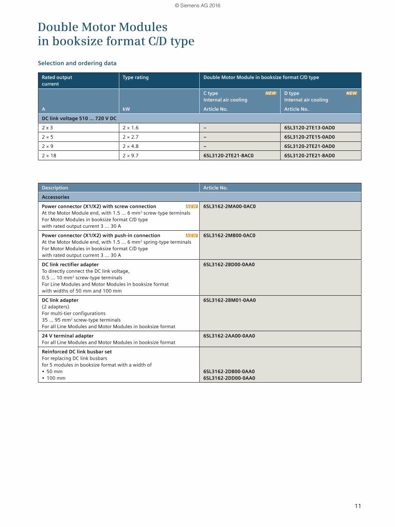
Rated output current
Type rating Double Motor Module in booksize format C/D type
C type Internal air cooling
D type Internal air cooling
A kW Article No. Article No.
DC link voltage 510 ... 720 V DC
2 x 3 2 × 1.6 – 6SL3120-2TE13-0AD0
2 × 5 2 × 2.7 – 6SL3120-2TE15-0AD0
2 × 9 2 × 4.8 – 6SL3120-2TE21-0AD0
2 × 18 2 × 9.7 6SL3120-2TE21-8AC0 6SL3120-2TE21-8AD0
Description Article No.
Accessories
Power connector (X1/X2) with screw connection At the Motor Module end, with 1.5 ... 6 mm2 screw-type terminals For Motor Modules in booksize format C/D type with rated output current 3 ... 30 A
6SL3162-2MA00-0AC0
Power connector (X1/X2) with push-in connection At the Motor Module end, with 1.5 ... 6 mm2 spring-type terminals For Motor Modules in booksize format C/D type with rated output current 3 ... 30 A
6SL3162-2MB00-0AC0
DC link rectifier adapterTo directly connect the DC link voltage, 0.5 ... 10 mm2 screw-type terminals For Line Modules and Motor Modules in booksize format with widths of 50 mm and 100 mm
6SL3162-2BD00-0AA0
DC link adapter(2 adapters) For multi-tier configurations 35 … 95 mm2 screw-type terminals For all Line Modules and Motor Modules in booksize format
6SL3162-2BM01-0AA0
24 V terminal adapterFor all Line Modules and Motor Modules in booksize format
6SL3162-2AA00-0AA0
Reinforced DC link busbar setFor replacing DC link busbars for 5 modules in booksize format with a width of• 50 mm• 100 mm
6SL3162-2DB00-0AA0 6SL3162-2DD00-0AA0
Selection and ordering data
Double Motor Modules in booksize format C/D type
© Siemens AG 2016
12
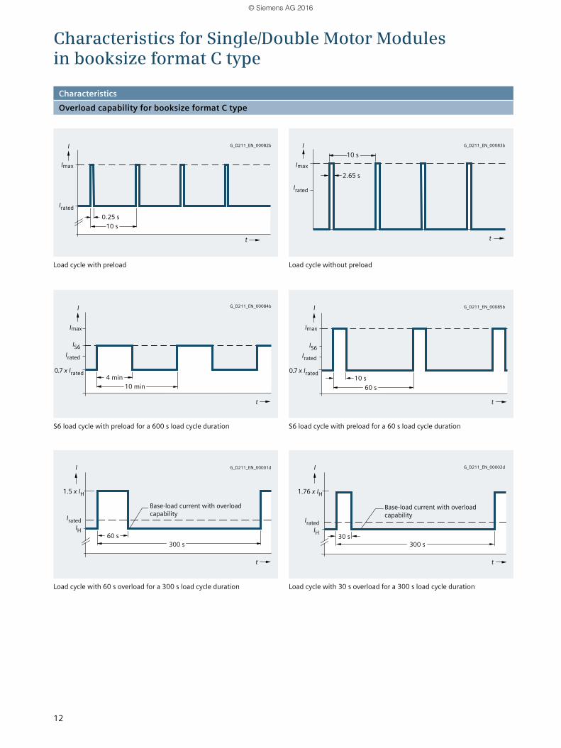
Load cycle with preload
S6 load cycle with preload for a 600 s load cycle duration
Load cycle with 60 s overload for a 300 s load cycle duration
Load cycle without preload
S6 load cycle with preload for a 60 s load cycle duration
Load cycle with 30 s overload for a 300 s load cycle duration
Characteristics for Single/Double Motor Modules in booksize format C type
Base-load current with overload capability
Base-load current with overload capability
2.65 s
0.25 s
4 min10 min 60 s
60 s
10 s
30 s300 s300 s
10 s
10 s
II
I I
I I
IS6 IS6
0.7 x Irated
1.5 x IH 1.76 x IH
0.7 x Irated
t
t
tt
t
t
Irated
Irated
Irated
Irated IratedIH IH
Irated
CharacteristicsOverload capability for booksize format C type
G_D211_EN_00084b
G_D211_EN_00082b G_D211_EN_00083b
G_D211_EN_00085b
G_D211_EN_00001d G_D211_EN_00002d
Imax
Imax Imax
Imax
© Siemens AG 2016
13
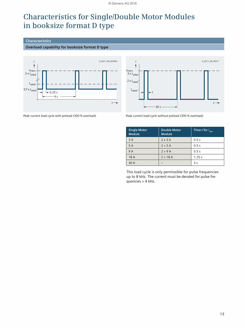
Peak current load cycle with preload (300 % overload) Peak current load cycle without preload (300 % overload)
CharacteristicsOverload capability for booksize format D type
Single Motor Module
Double Motor Module
Time t for Imax
3 A 2 x 3 A 0.5 s
5 A 2 × 5 A 0.5 s
9 A 2 × 9 A 0.5 s
18 A 2 × 18 A 1.25 s
30 A – 3 s
This load cycle is only permissible for pulse frequencies up to 8 kHz. The current must be derated for pulse fre- quencies > 4 kHz.
Characteristics for Single/Double Motor Modules in booksize format D type
0.25 s
30 s
t4 s
Imax= Imax=
I I
t t
Irated
Irated
3 x Irated 3 x Irated
2 x Irated
0.7 x Irated
G_D211_EN_00317G_D211_EN_00300a
© Siemens AG 2016

14
Load cycle with preload
S6 load cycle with preload for a 600 s load cycle duration
Load cycle with 60 s overload for a 300 s load cycle duration
Load cycle without preload
S6 load cycle with preload for a 60 s load cycle duration
Load cycle with 30 s overload for a 300 s load cycle duration
Characteristics for Single/Double Motor Modules in booksize format D type
Base-load current with overload capability
Base-load current with overload capability
2.65 s
60 s 30 s300 s300 s
10 s
I I
IS6 IS6
0.7 x Irated 0.7 x Irated
1.5 x IH 1.76 x IH
t t
tt
tt
Irated
Irated
Irated Irated
Irated IratedIH IH
CharacteristicsOverload capability for booksize format D type
G_D211_EN_00334
G_D211_EN_00331 G_D211_EN_00332
G_D211_EN_00333
G_D211_EN_00001d G_D211_EN_00002d
2 x Irated 2 x Irated
2 x Irated
0.25 s
10 min 60 s
10 s
4 min 10 s
© Siemens AG 2016
15
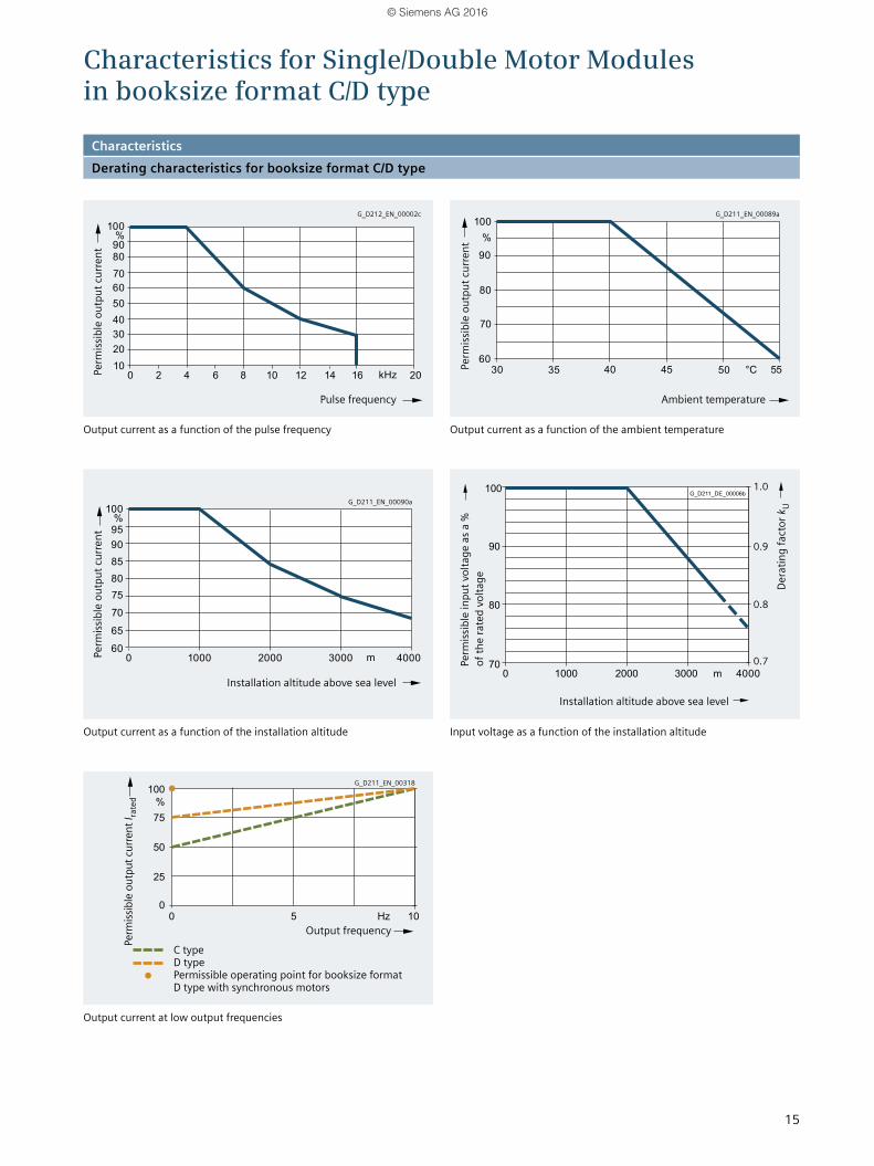
Output current as a function of the pulse frequency
Output current as a function of the installation altitude
C type D type Permissible operating point for booksize format D type with synchronous motors
Output current as a function of the ambient temperature
Input voltage as a function of the installation altitude
Output current at low output frequencies
Characteristics for Single/Double Motor Modules in booksize format C/D type
Perm
issib
le o
utpu
t cur
rent
Perm
issib
le o
utpu
t cur
rent
Pulse frequency
Installation altitude above sea level
Output frequency
Installation altitude above sea level
Dera
ting
fact
or k
U
Ambient temperature
Perm
issib
le o
utpu
t cur
rent
Perm
issib
le in
put v
olta
ge a
s a %
of
the
rate
d vo
ltage
Perm
issib
le o
utpu
t cur
rent
I rate
d
CharacteristicsDerating characteristics for booksize format C/D type
G_D212_EN_00002c G_D211_EN_00089a
G_D211_EN_00090a
G_D211_EN_00318
1.0
0.9
0.8
0.7
© Siemens AG 2016
16
MOTION-CONNECT power cables for SINAMICS S120 Motor Modules in booksize format C/D type
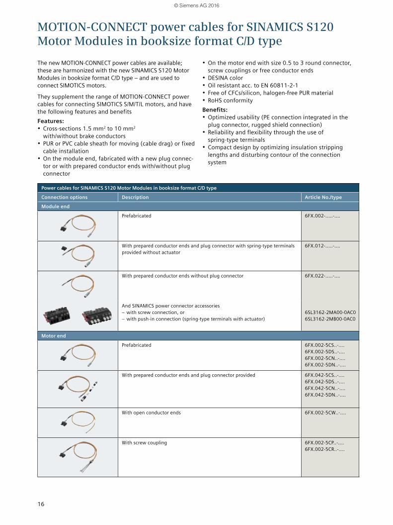
The new MOTION-CONNECT power cables are available; these are harmonized with the new SINAMICS S120 Motor Modules in booksize format C/D type – and are used to connect SIMOTICS motors.
They supplement the range of MOTION-CONNECT power cables for connecting SIMOTICS S/M/T/L motors, and have the following features and benefitsFeatures:• Cross-sections 1.5 mm2 to 10 mm2
with/without brake conductors• PUR or PVC cable sheath for moving (cable drag) or fixed
cable installation• On the module end, fabricated with a new plug connec-
tor or with prepared conductor ends with/without plug connector
• On the motor end with size 0.5 to 3 round connector, screw couplings or free conductor ends
• DESINA color• Oil resistant acc. to EN 60811-2-1• Free of CFCs/silicon, halogen-free PUR material• RoHS conformityBenefits:• Optimized usability (PE connection integrated in the
plug connector, rugged shield connection)• Reliability and flexibility through the use of
spring-type terminals• Compact design by optimizing insulation stripping
lengths and disturbing contour of the connection system
Power cables for SINAMICS S120 Motor Modules in booksize format C/D type
Connection options Description Article No./type
Module end
Prefabricated 6FX.002-..…-.…
With prepared conductor ends and plug connector with spring-type terminals provided without actuator
6FX.012-..…-.…
With prepared conductor ends without plug connector 6FX.022-..…-.…
And SINAMICS power connector accessories – with screw connection, or – with push-in connection (spring-type terminals with actuator)
6SL3162-2MA00-0AC0 6SL3162-2MB00-0AC0
Motor end
Prefabricated 6FX.002-5CS..-.... 6FX.002-5DS..-.... 6FX.002-5CN..-.... 6FX.002-5DN..-....
With prepared conductor ends and plug connector provided 6FX.042-5CS..-.... 6FX.042-5DS..-.... 6FX.042-5CN..-.... 6FX.042-5DN..-....
With open conductor ends 6FX.002-5CW..-....
With screw coupling 6FX.002-5CP..-.... 6FX.002-5CR..-....
© Siemens AG 2016
17
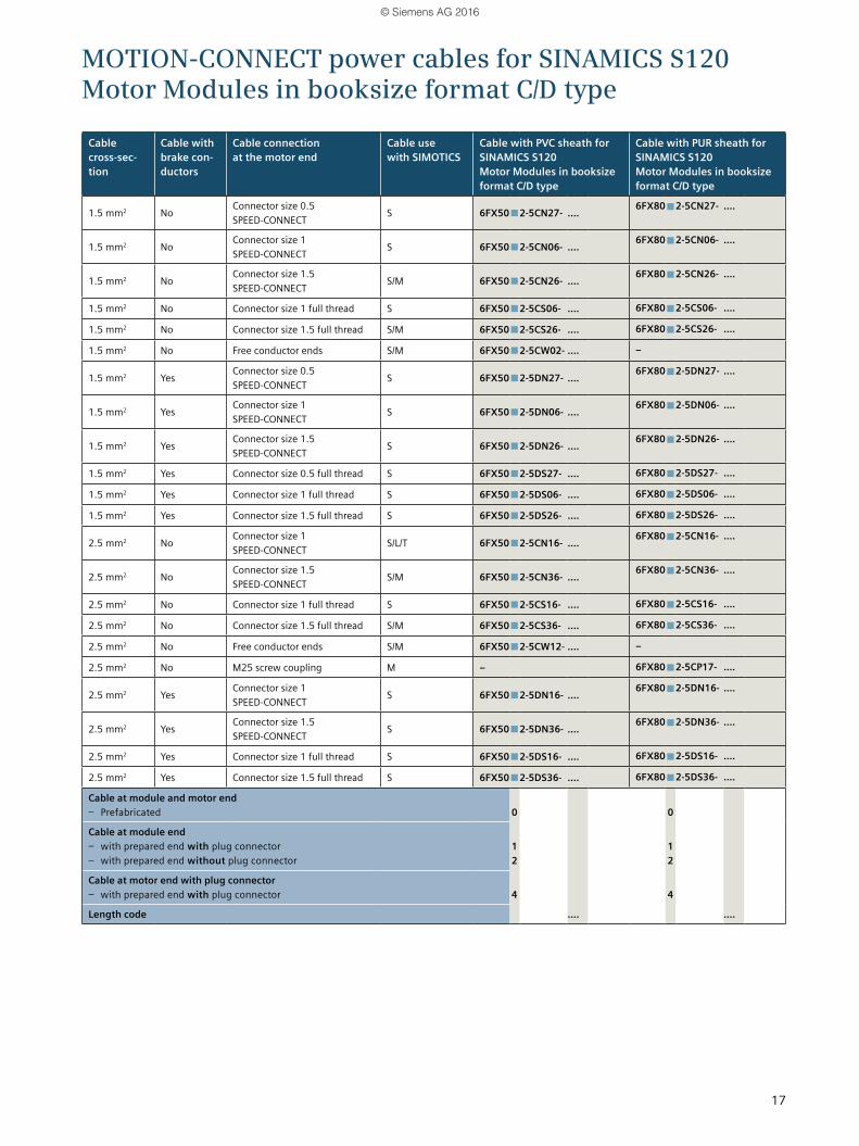
MOTION-CONNECT power cables for SINAMICS S120 Motor Modules in booksize format C/D type
Cable cross-sec-tion
Cable with brake con-ductors
Cable connection at the motor end
Cable use with SIMOTICS
Cable with PVC sheath for SINAMICS S120 Motor Modules in booksize format C/D type
Cable with PUR sheath for SINAMICS S120 Motor Modules in booksize format C/D type
1.5 mm2 NoConnector size 0.5 SPEED-CONNECT
S 6FX50■2-5CN27- ....6FX80■2-5CN27- ....
1.5 mm2 NoConnector size 1 SPEED-CONNECT
S 6FX50■2-5CN06- ....6FX80■2-5CN06- ....
1.5 mm2 NoConnector size 1.5 SPEED-CONNECT
S/M 6FX50■2-5CN26- ....6FX80■2-5CN26- ....
1.5 mm2 No Connector size 1 full thread S 6FX50■2-5CS06- .... 6FX80■2-5CS06- ....
1.5 mm2 No Connector size 1.5 full thread S/M 6FX50■2-5CS26- .... 6FX80■2-5CS26- ....
1.5 mm2 No Free conductor ends S/M 6FX50■2-5CW02- .... –
1.5 mm2 YesConnector size 0.5 SPEED-CONNECT
S 6FX50■2-5DN27- ....6FX80■2-5DN27- ....
1.5 mm2 YesConnector size 1 SPEED-CONNECT
S 6FX50■2-5DN06- ....6FX80■2-5DN06- ....
1.5 mm2 YesConnector size 1.5 SPEED-CONNECT
S 6FX50■2-5DN26- ....6FX80■2-5DN26- ....
1.5 mm2 Yes Connector size 0.5 full thread S 6FX50■2-5DS27- .... 6FX80■2-5DS27- ....
1.5 mm2 Yes Connector size 1 full thread S 6FX50■2-5DS06- .... 6FX80■2-5DS06- ....
1.5 mm2 Yes Connector size 1.5 full thread S 6FX50■2-5DS26- .... 6FX80■2-5DS26- ....
2.5 mm2 NoConnector size 1 SPEED-CONNECT
S/L/T 6FX50■2-5CN16- ....6FX80■2-5CN16- ....
2.5 mm2 NoConnector size 1.5 SPEED-CONNECT
S/M 6FX50■2-5CN36- ....6FX80■2-5CN36- ....
2.5 mm2 No Connector size 1 full thread S 6FX50■2-5CS16- .... 6FX80■2-5CS16- ....
2.5 mm2 No Connector size 1.5 full thread S/M 6FX50■2-5CS36- .... 6FX80■2-5CS36- ....
2.5 mm2 No Free conductor ends S/M 6FX50■2-5CW12- .... –
2.5 mm2 No M25 screw coupling M – 6FX80■2-5CP17- ....
2.5 mm2 YesConnector size 1 SPEED-CONNECT
S 6FX50■2-5DN16- ....6FX80■2-5DN16- ....
2.5 mm2 YesConnector size 1.5 SPEED-CONNECT
S 6FX50■2-5DN36- ....6FX80■2-5DN36- ....
2.5 mm2 Yes Connector size 1 full thread S 6FX50■2-5DS16- .... 6FX80■2-5DS16- ....
2.5 mm2 Yes Connector size 1.5 full thread S 6FX50■2-5DS36- .... 6FX80■2-5DS36- ....
Cable at module and motor end – Prefabricated
0
0
Cable at module end – with prepared end with plug connector – with prepared end without plug connector
1 2
1 2
Cable at motor end with plug connector – with prepared end with plug connector
4
4
Length code .... ....
© Siemens AG 2016
18
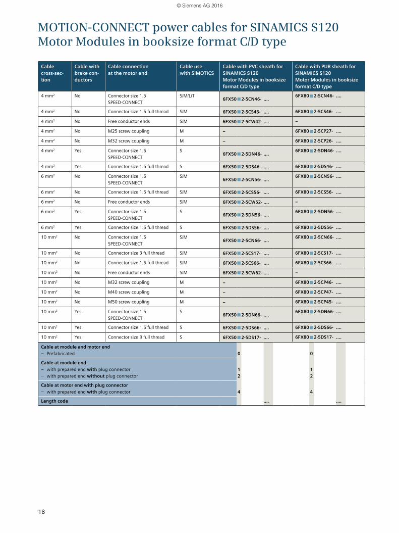
MOTION-CONNECT power cables for SINAMICS S120 Motor Modules in booksize format C/D type
Cable cross-sec-tion
Cable with brake con-ductors
Cable connection at the motor end
Cable use with SIMOTICS
Cable with PVC sheath for SINAMICS S120 Motor Modules in booksize format C/D type
Cable with PUR sheath for SINAMICS S120 Motor Modules in booksize format C/D type
4 mm2 No Connector size 1.5 SPEED-CONNECT
S/M/L/T6FX50■2-5CN46- ....
6FX80■2-5CN46- ....
4 mm2 No Connector size 1.5 full thread S/M 6FX50■2-5CS46- .... 6FX80■2-5CS46- ....
4 mm2 No Free conductor ends S/M 6FX50■2-5CW42- .... –
4 mm2 No M25 screw coupling M – 6FX80■2-5CP27- ....
4 mm2 No M32 screw coupling M – 6FX80■2-5CP26- ....
4 mm2 Yes Connector size 1.5 SPEED-CONNECT
S6FX50■2-5DN46- ....
6FX80■2-5DN46- ....
4 mm2 Yes Connector size 1.5 full thread S 6FX50■2-5DS46- .... 6FX80■2-5DS46- ....
6 mm2 No Connector size 1.5 SPEED-CONNECT
S/M6FX50■2-5CN56- ....
6FX80■2-5CN56- ....
6 mm2 No Connector size 1.5 full thread S/M 6FX50■2-5CS56- .... 6FX80■2-5CS56- ....
6 mm2 No Free conductor ends S/M 6FX50■2-5CW52- .... –
6 mm2 Yes Connector size 1.5 SPEED-CONNECT
S6FX50■2-5DN56- ....
6FX80■2-5DN56- ....
6 mm2 Yes Connector size 1.5 full thread S 6FX50■2-5DS56- .... 6FX80■2-5DS56- ....
10 mm2 No Connector size 1.5 SPEED-CONNECT
S/M6FX50■2-5CN66- ....
6FX80■2-5CN66- ....
10 mm2 No Connector size 3 full thread S/M 6FX50■2-5CS17- .... 6FX80■2-5CS17- ....
10 mm2 No Connector size 1.5 full thread S/M 6FX50■2-5CS66- .... 6FX80■2-5CS66- ....
10 mm2 No Free conductor ends S/M 6FX50■2-5CW62- .... –
10 mm2 No M32 screw coupling M – 6FX80■2-5CP46- ....
10 mm2 No M40 screw coupling M – 6FX80■2-5CP47- ....
10 mm2 No M50 screw coupling M – 6FX80■2-5CP45- ....
10 mm2 Yes Connector size 1.5 SPEED-CONNECT
S6FX50■2-5DN66- ....
6FX80■2-5DN66- ....
10 mm2 Yes Connector size 1.5 full thread S 6FX50■2-5DS66- .... 6FX80■2-5DS66- ....
10 mm2 Yes Connector size 3 full thread S 6FX50■2-5DS17- .... 6FX80■2-5DS17- ....
Cable at module and motor end – Prefabricated
0
0
Cable at module end – with prepared end with plug connector – with prepared end without plug connector
1 2
1 2
Cable at motor end with plug connector – with prepared end with plug connector
4
4
Length code .... ....
© Siemens AG 2016
19
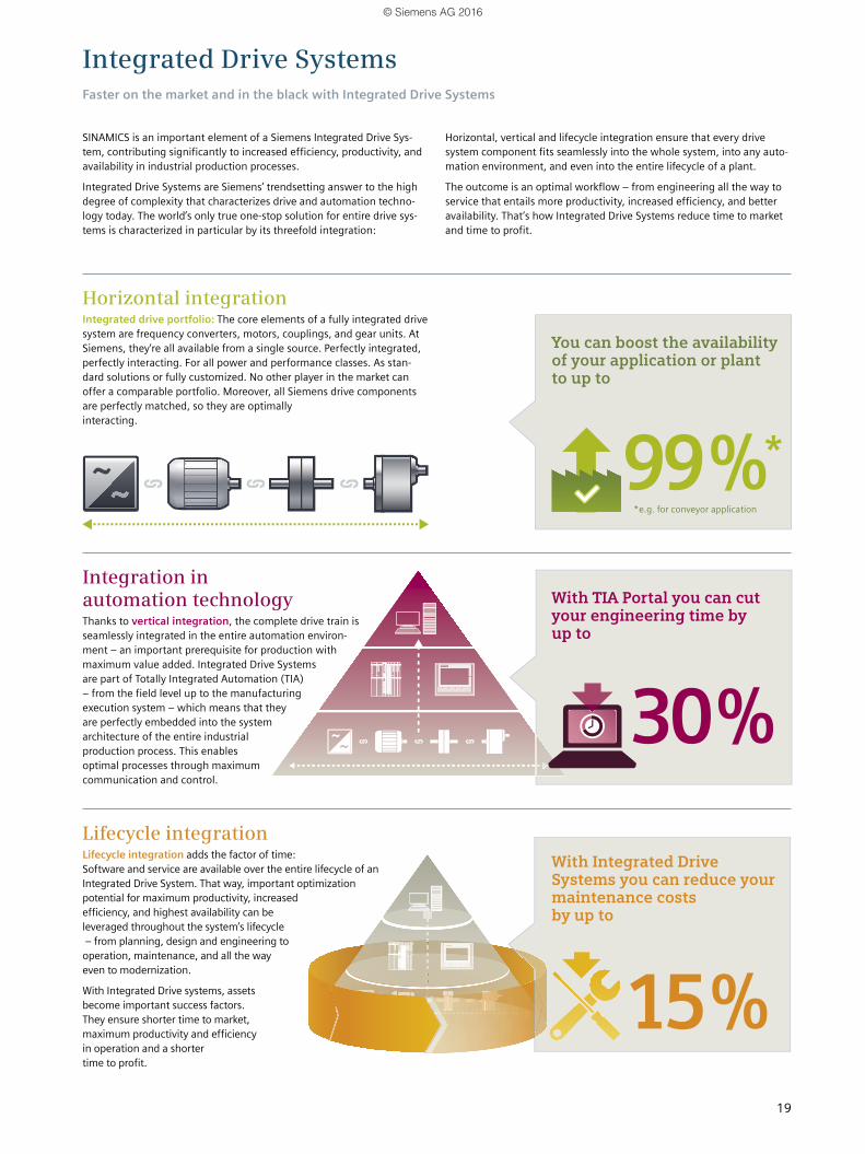
SINAMICS is an important element of a Siemens Integrated Drive Sys-tem, contributing significantly to increased efficiency, productivity, and availability in industrial production processes.
Integrated Drive Systems are Siemens’ trendsetting answer to the high degree of complexity that characterizes drive and automation techno- logy today. The world’s only true one-stop solution for entire drive sys-tems is characterized in particular by its threefold integration:
Integrated Drive SystemsFaster on the market and in the black with Integrated Drive Systems
Horizontal integrationIntegrated drive portfolio: The core elements of a fully integrated drive system are frequency converters, motors, couplings, and gear units. At Siemens, they’re all available from a single source. Perfectly integrated, perfectly interacting. For all power and performance classes. As stan-dard solutions or fully customized. No other player in the market can offer a comparable portfolio. Moreover, all Siemens drive components are perfectly matched, so they are optimally interacting.
Integration in automation technologyThanks to vertical integration, the complete drive train is seamlessly integrated in the entire automation environ- ment – an important prerequisite for production with maximum value added. Integrated Drive Systems are part of Totally Integrated Automation (TIA) – from the field level up to the manufacturing execution system – which means that they are perfectly embedded into the system architecture of the entire industrial production process. This enables optimal processes through maximum communication and control.
Lifecycle integrationLifecycle integration adds the factor of time: Software and service are available over the entire lifecycle of an Integrated Drive System. That way, important optimization potential for maximum productivity, increased efficiency, and highest availability can be leveraged throughout the system’s lifecycle – from planning, design and engineering to operation, maintenance, and all the way even to modernization.
With Integrated Drive systems, assets become important success factors. They ensure shorter time to market, maximum productivity and efficiency in operation and a shorter time to profit.
Horizontal, vertical and lifecycle integration ensure that every drive system component fits seamlessly into the whole system, into any auto-mation environment, and even into the entire lifecycle of a plant.
The outcome is an optimal workflow – from engineering all the way to service that entails more productivity, increased efficiency, and better availability. That’s how Integrated Drive Systems reduce time to market and time to profit.
You can boost the availability of your application or plant to up to
*e.g. for conveyor application
With TIA Portal you can cut your engineering time by up to
With Integrated Drive Systems you can reduce your maintenance costs by up to
© Siemens AG 2016
Find out more:
siemens.com/ids
Subject to change without prior notice Article No.: 6ZB5471-0AT02-0AA0 Dispo 18404 V6.MKKATA.GMC.131 BR 1115 1. SB/WÜ 20 En Nd 1116 1. SB/WÜ 20 En Printed in Germany © Siemens AG 2015
The information provided in this brochure contains merely general descriptions or performance characteristics which in case of actual use do not always apply as described or which may change as a result of further development of the products. An obligation to provide the respective characteristics shall only exist if expressly agreed in the terms of contract.
All product designations may be trademarks or product names of Siemens AG or other supplier companies whose use by third parties for their own purposes could violate the rights of the owners.
Follow us on: twitter.com/siemensindustry youtube.com/siemens
See for yourself how Integrated Drive Systems enhance the competitiveness of production plants and entire companies in every sector.
The advan-tages of Integrated Drive Systems at a glance
Siemens AG Digital Factory Motion Control Postfach 31 80 91050 ERLANGEN GERMANY
© Siemens AG 2016